US6568647B2 - Mounting apparatus for a deformable mirror - Google Patents
Mounting apparatus for a deformable mirrorDownload PDFInfo
- Publication number
- US6568647B2 US6568647B2US09/769,874US76987401AUS6568647B2US 6568647 B2US6568647 B2US 6568647B2US 76987401 AUS76987401 AUS 76987401AUS 6568647 B2US6568647 B2US 6568647B2
- Authority
- US
- United States
- Prior art keywords
- mounting
- mirror
- base member
- ring
- screws
- Prior art date
- Legal status (The legal status is an assumption and is not a legal conclusion. Google has not performed a legal analysis and makes no representation as to the accuracy of the status listed.)
- Expired - Lifetime, expires
Links
- 230000002093peripheral effectEffects0.000claimsabstractdescription25
- 230000004075alterationEffects0.000description13
- 230000003044adaptive effectEffects0.000description12
- 239000000463materialSubstances0.000description12
- 230000003287optical effectEffects0.000description11
- PCHJSUWPFVWCPO-UHFFFAOYSA-NgoldChemical compound[Au]PCHJSUWPFVWCPO-UHFFFAOYSA-N0.000description9
- 239000010931goldSubstances0.000description9
- 229910052737goldInorganic materials0.000description9
- 238000000034methodMethods0.000description7
- 230000008602contractionEffects0.000description5
- 230000005540biological transmissionEffects0.000description3
- 238000012937correctionMethods0.000description3
- 230000007812deficiencyEffects0.000description3
- 230000013011matingEffects0.000description3
- 201000009310astigmatismDiseases0.000description2
- 230000008901benefitEffects0.000description2
- 238000010276constructionMethods0.000description2
- 230000000694effectsEffects0.000description2
- 238000007747platingMethods0.000description2
- 238000012545processingMethods0.000description2
- 210000001747pupilAnatomy0.000description2
- 230000009467reductionEffects0.000description2
- 239000004593EpoxySubstances0.000description1
- 239000004677NylonSubstances0.000description1
- 239000000853adhesiveSubstances0.000description1
- 230000001070adhesive effectEffects0.000description1
- 230000006399behaviorEffects0.000description1
- 238000005452bendingMethods0.000description1
- 239000004020conductorSubstances0.000description1
- 230000005684electric fieldEffects0.000description1
- 210000003128headAnatomy0.000description1
- 238000010438heat treatmentMethods0.000description1
- 230000001939inductive effectEffects0.000description1
- 238000009434installationMethods0.000description1
- 229910052745leadInorganic materials0.000description1
- 238000004519manufacturing processMethods0.000description1
- 238000005259measurementMethods0.000description1
- 239000002184metalSubstances0.000description1
- 229910052751metalInorganic materials0.000description1
- 238000012986modificationMethods0.000description1
- 230000004048modificationEffects0.000description1
- 229920001778nylonPolymers0.000description1
- 239000013307optical fiberSubstances0.000description1
- 230000010076replicationEffects0.000description1
- 230000004044responseEffects0.000description1
- 230000003068static effectEffects0.000description1
Images


Classifications
- G—PHYSICS
- G02—OPTICS
- G02B—OPTICAL ELEMENTS, SYSTEMS OR APPARATUS
- G02B26/00—Optical devices or arrangements for the control of light using movable or deformable optical elements
- G02B26/08—Optical devices or arrangements for the control of light using movable or deformable optical elements for controlling the direction of light
- G02B26/0816—Optical devices or arrangements for the control of light using movable or deformable optical elements for controlling the direction of light by means of one or more reflecting elements
- G02B26/0825—Optical devices or arrangements for the control of light using movable or deformable optical elements for controlling the direction of light by means of one or more reflecting elements the reflecting element being a flexible sheet or membrane, e.g. for varying the focus
Definitions
- the present inventionrelates to a mounting apparatus for mounting a deformable curvature mirror of the type that is capable of controlled deformation by the application of electrical voltages to mirror electrodes on the back side of the mirror with the voltages controlled by the use of a wavefront sensor in an adaptive optics system.
- adaptive optics methods and deviceswhich include a wavefront sensor for sensing the aberrations in the wavefront of light waves and then correcting or compensating for those aberrations, such as the atmospheric aberrations that effect the viewing of stars and planets through a telescope.
- the existing methods and devices for sensing and measuring the wavefrontinclude several interferometric techniques, the Shack-Hartmann wavefront sensing techniques and various other systems involving the projection of patterns of light through an optical system.
- Such prior techniques and systemsare typically complex and expensive, as well as having various inherent deficiencies.
- the deformable mirrors that are controlled by those wavefront sensors for adaptive opticsalso include numerous deficiencies.
- the Shack-Hartmann system mirroris comprised of a multiplicity of push rods engaging the back of a flexible mirror and the extension-retraction of each push rod is controlled by the Shack-Hartmann wavefront sensor, but the push rods tend to produce a straight line on the mirror surface between each pair of adjacent push rods that is not truly representative of the curvatures of a wavefront.
- the number of push rods and, therefore, the closeness of the push rodsis physically limited, as well as the length of their travel, whereby the accuracy and degree of optical correction that can be applied by the Shack-Hartmann type mirror is limited.
- some other wavefront sensing and deformable mirror techniques and devicesare not directly applicable to all types of adaptive optics for correcting the wavefront to thereby correct the image.
- a deformable curvature mirrorthat solves many of the problems of the prior art deformable mirrors has been developed by the inventors hereof and is the subject of separate, concurrently filed U.S. patent application entitled “Deformable Curvature Mirror”, which mirror is useable in an adaptive optics system having a wavefront sensor described and shown in the copending U.S. patent application Ser. No. 09/579,786, filed May 26, 2000, issued on Sep. 17, 2002, as U.S. Pat. No. 6,452,145, by the inventors hereof. While such deformable curvature mirror and wavefront sensor greatly improve the capabilities of an adaptive optics system, it has been discovered that the mounting of the unique deformable curvature mirror is critical to optimizing the performance of that mirror.
- the deformable curvature mirror of the inventors' copending patent applicationis comprised of a laminate of two electro-restrictive disks, such as of PZT material, with a mirrored layer on one side, a pattern of electrodes on the opposite side and an electrically grounded metallic layer sandwiched therebetween, whereby the application of variable electric voltages to the electrodes causes controlled expansion and contraction of the electro-restrictive material to thereby controllably deform the mirror surface.
- the proper mounting and support of the laminated disksis critical to avoiding undesirable mechanical deformation of the laminated disks during mounting and also to allow the desired deformation of the laminated disks by the applied voltages.
- the laminated disks of the deformable curvature mirrorare subjected to various plating and heating steps, it is virtually impossible to produce a completely flat mounting surface on the mirror from which it can be supported.
- a further object of the present inventionis to provide such a mounting apparatus whereby opposed adjustable means are provided on opposite sides of the peripheral portion of the mirror at a plurality of locations for selectively adjusting the mounting force and direction applied to the mirror perimeter at each such location, including for purposes of mechanically flattening the deformable curvature mirror from its as-manufactured condition.
- a still further object of the present inventionis to provide such a mounting apparatus having a plurality of adjustable screws on opposite sides of the deformable curvature mirror, which screws engage a rubber o-ring on each side of the mirror perimeter for adjustably and firmly mounting the mirror by selectively advancing and retracting individual screws.
- FIG. 1is a diagrammatic illustration of a typical optical system, namely, a telescope, provided with an adaptive optics system that includes the deformable curvature mirror mounting apparatus of the present invention
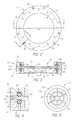
- FIG. 2is an enlarged plan view of the mounting apparatus for the deformable mirror of the present invention taken on the line 2 — 2 in FIG. 1;
- FIG. 3is a sectional elevation view of the mounting apparatus taken substantially on the line 3 — 3 in FIG. 2;
- FIG. 4is an enlarged, fragmentary sectional view taken substantially on the line 4 — 4 in FIG. 2;
- FIG. 5is a bottom view, on a reduced scale, of a typical deformable curvature mirror separated from the mounting apparatus of the present invention for clarity of illustration.
- an optical systemsuch as a telescope 10
- an adaptive optics systemthat includes the deformable curvature mirror 14 supported by the mounting apparatus 16 of the present invention.
- Light rays R from any light source Lsuch as the illustrated star when the telescope 10 is used for observing stars and planets, enter the telescope 10 through a lens 18 that focuses the light rays on an object image plane OIP where the image of the light source L (here a star, for example) exists in focus but is uncollected.
- the telescope 10also may be of a type and construction for receiving light waves from an earth-bound data transmission station L, such as in a system for transmitting data from building-to-building, tower-to-tower or mountain-to-mountain.
- the light rays Rthen pass through a collimating lens 20 to the deformable mirror 14 .
- the light rays R reaching the telescope 10 from a distant star or other light source Ltheoretically would be parallel and in perfect alignment to produce a flat wavefront.
- the earth's atmospherecreates aberrations in the light rays R before reaching the telescope 10 , which aberrations vary with the atmospheric conditions and rapidly over any period of time, even when the telescope is located at high elevations.
- the telescope 10is used for viewing something on earth at a distance or for receiving light waves for data transmission from a station at a distance on earth, the earth's atmosphere will create aberrations in the light rays R and, therefore, produce a wavefront that is not perfectly flat and is constantly changing when it reaches the telescope 10 and the deformable mirror 14 .
- Various wavefront sensorshave been used to detect the variations in the wavefront caused by the atmospheric aberrations and then to compensate or correct for those aberrations by adaptive optics, such as by using a deformable mirror controlled by a wavefront sensor.
- One type of wavefront sensorthat is particularly suited for use with the deformable curvature mirror 14 described and shown in the concurrently filed U.S. patent application, Ser. No.
- the light rays Rreflect from the surface of the deformable mirror 14 to a lens 22 that refocuses the image on the plane of an image detector D.
- the lens 18 , collimating lens 20 , deformable mirror 14 , lens 22 and image detector Dare all located and centered on the optical axis O of the system.
- the image detector Dmay be of any convenient type that is suitable for the particular application of the system, such as a conventional detector in a video camera, a custom format of charge couple device (CCD), an array of PIN diodes, an array of lenslets focusing the light onto a like array of optical fibers, photon counting detectors, any digital photo detector, photo transmitter, or the like.
- the detector Dprovides images and/or data relative to the light intensity throughout the image focused on detector D and these images and/or data are displayed and/or recorded by an appropriate device 24 suitable for the particular application of the system.
- the image sensed by image detector Dwill be the uncorrected image entering the telescope 10 , i.e. without correction for aberrations, but when the deformable mirror 14 is appropriately deformed in the manner described in the aforesaid patent applications to compensate for the aberrations, the image detector D will detect and convey to the device 24 an image that eliminates the aberrations, i.e. a corrected image.
- the detector Dwill receive and detect corrected light rays when the deformable mirror 14 is properly deformed to correct for aberrations in the light rays R transmitted to the system illustrated in FIG. 1 . Further, when such a system is used for transmitting data by light rays, the wavefront can be sensed and corrected by the deformable mirror 14 before transmitting the light rays with the data light emitter positioned at the same location as image detector D.
- a prism or partial mirror 26is positioned on the optical axis O between lens 22 and detector D for reflecting a portion of the light rays R to a wavefront sensor S, such as one of the wavefront sensors disclosed in the inventors' aforementioned copending U.S. patent application Ser. No. 09/579,786.
- the wavefront sensor Ssenses two defocused pupil images (or the shapes and light intensities for some detectors used in a wavefront sensor S) which are communicated to the central processing unit CPU for processing by data reduction software to derive the wavefront curvature and provide data appropriate for the operation of the deformable mirror 14 .
- the wavefrontis derived or recovered by solving the Poisson equation with respect to intensities with the Dirichlet's boundary conditions relative to the shape.
- An iterative data reduction algorithm or other non-linear fitting techniquemay be employed to compensate for non-linearity in measurements in an open loop system.
- the CPUthen provides a plurality of separate and controlled high voltage electrical potentials to a plurality of conductive electrode segments (described below) on the back of deformable mirror 14 through a like plurality of separate wires W.
- the deformable mirror 14is fixedly mounted in the mounting apparatus 16 of the present invention that is appropriately positioned to reflect the optical axis O and light rays R from the collimating lens 20 to the detector D.
- the overall surface shape of the mirrorcan be modified by the application of high voltages applied to selected electrode segments of the deformable mirror 14 through one or more of the wires W and the curvature of the surface of the deformable mirror 14 may be modified for correcting aberrations by the application of controlled high voltages through other ones of the wires W.
- the deformable curvature mirror 14is shown in a top plan view (FIG. 2) and a sectional view (FIG. 3) diagrammatically with the thicknesses of some of the layers of the laminated construction exaggerated for ease of illustration and some layers omitted for clarity.
- the basic, physical structure of the deformable mirror 14is comprised of two disks or plates of any electro-restrictive material that exhibits controlled expansion and contraction in response to the application of an electrical potential across the material and yet the material has an adequate structural strength and rigidity to maintain a given shape, as distinguished from being flexible.
- a preferred materialis PZT, which is a piezoelectric material comprised of Pb, Zu, Ti and O though a possible alternative is a magnetorestrictive material known as PMN comprised of Pb, Mg, Nb and O.
- the plates of the electro-restrictive materialare separately ground to produce flat surfaces and a uniform thickness that depends on the size of the deformable mirror 14 but, in general, sufficiently thin to accommodate the flexures caused by the expansion and contraction induced by the electrical voltages.
- each of the PZT plates 30 and 32preferably would be less than one-quarter inch and more than one-sixteenth inch in thickness.
- a layer of gold or other highly conductive material(hereinafter referred to as a gold layer for convenience) is applied to the facing surfaces of the two plates and then the two plates are laminated together and joined by a conductive adhesive to form a laminated disk 30 .
- a plating mask(not shown) is applied to the bottom surface to create a predetermined pattern, such as the typical pattern shown in FIG. 5, and then gold layers are applied to the top and bottom surfaces of the disk.
- the mask and gold covering the mask on the bottom surfaceare removed to leave a pattern of gold electrodes 40 that are separated by small gaps formed by the mask.
- Electrical terminals 44are connected to each electrode 40 and the wires W are connected to the terminals for selectively supplying the variable high voltage to the electrodes 40 for causing the controlled deformation of the laminated disk 30 .
- a ground wireis connected to the upper and intermediate gold layers to complete the electrical circuit.
- a ground wire(not shown) is connected to the upper and intermediate gold layers to complete the electrical circuit (not shown).
- a mirror layer 48is applied to the upper surface of laminated disk 30 by any convenient means such as epoxy replication wherein the mirror layer 48 is first formed separately and then adhered to the upper surface.
- the outer surface of gold (or other metal) layer on the upper surfacemay be polished to a mirror-like condition, which may be adequate for some applications of the deformable mirror 14 .
- the mirror 14is disclosed wherein the upper and intermediate gold layers are all connected to ground and a positive or negative voltage may be applied to one or more of the wires W. Then at each electrode location an electric field is produced across the rear plate in proportion to the voltage that is applied. The mirror then bends as the result of an expansion or contraction of the rear plate against the front plate. The resulting bending moment produces curvature. By grounding the front plate undesirable thermal behaviors are avoided. By grounding both sides of the front plate, it will have the same thermal expansion characteristics as the rear when connected to a drive amplifier.
- the mounting support for the deformable curvature mirror 14is important to the optimum performance of the mirror because it effects both the dynamic and static properties of the mirror. Additional benefits arise when the mount can be used to tune out manufacturing flaws, such as astigmatism.
- the first resonant frequencyis confined to the first mode in the Bessel series for a drum head, which is pure focus.
- the deformations caused by the edge actuatorswill have more stroke when they have something to push against, thereby greatly improving the mirror performance in correction tip/tilt, astigmatism, or any other wavefront errors with large slope terms.
- the mounting apparatus 16 of the present inventionis illustrated in the drawings as being circular for mounting a round deformable curvature mirror 14 but it should be understood and will be readily apparent to those skilled in the art that the mirror 14 may be of a non-round shape for non-spherical optical applications, such as for lasers, whereby the mirror 14 and the mounting apparatus 16 may be of a square, rectangular, oval or other non-round shape.
- the deformable curvature mirror 14includes a peripheral mounting portion 14 a around the perimeter of the mirror 14 that is of an adequate width for mounting the mirror and has substantially parallel opposite sides.
- the peripheral mounting portion 14 ais radially beyond the pattern of electrodes 40 , as shown in FIG. 5, and radially beyond the mirror layer 48 , as shown in FIGS. 3 and 4, for supporting the mirror 14 directly on the laminated disk 30 rather than any portion of the mirror or electrodes.
- the mounting apparatus 16includes a base member 80 and a mounting ring 82 superimposed on the base member 80 with mating annular surfaces 80 a and 82 a. In the final assembly, the mating surfaces 80 a and 82 a are in full engagement and the mounting ring 82 is rigidly connected to the base member 80 by any convenient means, such as a plurality of threaded bolts 84 .
- the base member 80is provided with an annular groove 86 in a recessed peripheral portion of the base member 80 radially inward from the mating surface 80 a.
- a peripheral portion of the mounting ring 82is provided with a similar groove 88 of the same diameter so that groove 88 is directly above groove 86 , as shown in FIGS. 3 and 4.
- Pliable meanssuch as o-rings 90 and 92 , are positioned in grooves 86 and 88 , respectively, and are of a sufficient thickness to extend above the surfaces of the respective grooves both before the base member 80 and mounting ring 82 are assembled and during all adjustments thereof.
- the groovesare of a depth significantly less than the thickness or height of the o-rings 90 and 92 .
- any flexible or compressible meansmay be used.
- the pliable meansextend continuously around the perimeter, as a rubber o-ring does, individual or segments of pliable means that extend only a limited circumferential distance may also be used.
- a plurality of set screws 94are threadedly mounted on the base member 80 in alignment with the groove 86 and circumferentially spaced around the base member.
- a like plurality of set screws 96are threadedly mounted in the mounting ring 82 and preferably directly opposite the set screws 94 .
- the bolts 84are removed and the mounting ring 82 is separated from the base member 80 .
- the wires Ware fed through the bottom of the base member 80 , such as into a conduit, and the mirror 14 is positioned in the base member 80 within the recessed portion, which is of a larger outer diameter than the outside diameter of the mirror 14 to allow centering of the mirror 14 in the base member 80 .
- the diameter of the o-ring groove 86is less than the outer diameter of the mirror 14 such that the o-ring 90 engages the peripheral mounting portion 14 a of the mirror.
- the mounting ring 82is positioned on the base member 80 with the o-ring 92 engaging the other side of the peripheral mounting portion 14 a of the mirror 14 and the bolts 84 are installed.
- the mirror 14is centered in the mounting apparatus 16 before the bolts 84 are completely tightened and a plurality of set screws 98 that are provided in the perimeter of the base member 80 are advanced to engage the perimeter edge 14 b of the mirror to maintain the mirror in the centered location.
- the perimeter set screws 98preferably have a soft tip, such as nylon tip 98 a, for resiliently engaging the perimeter of the laminated disk 30 portion of the mirror to avoid inducing an excessive stress in the somewhat brittle electro-restrictive material.
- the bolts 84are then tightened so that the surfaces 80 a and 82 a are firmly engaged.
- the vertical dimensions (perpendicular to the plane of the mirror 14 ) of the base member 80 , mounting ring 82 , grooves 86 , 88 , o-rings 90 , 92 and peripheral mounting portion 14 aare such that the o-rings 90 , 92 are slightly compressed for firmly but resiliently supporting the peripheral mounting portion 14 a of the mirror with the set screws 94 and 96 completely retracted.
- the set screws 94 and 96may be advanced and retracted to properly support and securely mount the mirror 14 by the peripheral mounting portion 14 a. It is preferred that opposing pairs of set screws 94 , 96 be adjusted concurrently so that an appropriate resilient force is applied to both sides of the peripheral mounting portion 14 a at the location of each pair of set screws 94 , 96 rather than, for example, making all of the adjustments by only the set screws 94 or 96 on one side of the mounting apparatus 16 .
- the mounting apparatus 16 and mirror 14may be adjusted by the set screws 94 , 96 to achieve the optimum surface configuration of the mirror 14 that is achievable by mechanical means, i.e. without the application of voltages to the electrodes 40 .
- the wavefront sensor and controlssuch as a wavefront sensor S and CPU, may be used to apply controlled voltages selectively to one or more of the plurality of electrodes 40 for further calibrating the mirror 14 to a completely flat or other desired shape.
- any conventional meansbe used to lock the set screws 94 , 96 in their adjusted positions, such as Loctite®, or other material to fill the hole above the set screws.
- the set screws 94 , 96may be of a self-locking type to avoid tampering or inadvertent changes in the adjusted positions of the screws.
Landscapes
- Physics & Mathematics (AREA)
- General Physics & Mathematics (AREA)
- Optics & Photonics (AREA)
- Optical Elements Other Than Lenses (AREA)
Abstract
Description
Claims (16)
Priority Applications (1)
| Application Number | Priority Date | Filing Date | Title |
|---|---|---|---|
| US09/769,874US6568647B2 (en) | 2001-01-25 | 2001-01-25 | Mounting apparatus for a deformable mirror |
Applications Claiming Priority (1)
| Application Number | Priority Date | Filing Date | Title |
|---|---|---|---|
| US09/769,874US6568647B2 (en) | 2001-01-25 | 2001-01-25 | Mounting apparatus for a deformable mirror |
Publications (2)
| Publication Number | Publication Date |
|---|---|
| US20020097509A1 US20020097509A1 (en) | 2002-07-25 |
| US6568647B2true US6568647B2 (en) | 2003-05-27 |
Family
ID=25086770
Family Applications (1)
| Application Number | Title | Priority Date | Filing Date |
|---|---|---|---|
| US09/769,874Expired - LifetimeUS6568647B2 (en) | 2001-01-25 | 2001-01-25 | Mounting apparatus for a deformable mirror |
Country Status (1)
| Country | Link |
|---|---|
| US (1) | US6568647B2 (en) |
Cited By (14)
| Publication number | Priority date | Publication date | Assignee | Title |
|---|---|---|---|---|
| US20040101310A1 (en)* | 2002-11-21 | 2004-05-27 | Wang Michael Sujue | Computer pen apparatus |
| US20040201908A1 (en)* | 2002-10-16 | 2004-10-14 | Olympus Corporation | Variable-shape reflection mirror and method of manufacturing the same |
| US20050069322A1 (en)* | 2003-09-29 | 2005-03-31 | Harris Corporation | Free space optical (FSO) device providing power reduction features and related methods |
| US20050069323A1 (en)* | 2003-09-29 | 2005-03-31 | Harris Corporation, Corporation Of The State Of Delaware | Modular free space optical (FSO) device and related methods |
| US20050069324A1 (en)* | 2003-09-29 | 2005-03-31 | Harris Corporation | Free space optical (FSO) device providing remote control features and related methods |
| US20050180753A1 (en)* | 2004-02-12 | 2005-08-18 | Adaptive Optics Associates, Inc. | Free space optical (FSO) laser communication system employing fade mitigation measures based on laser beam speckle tracking and locking principles |
| US20060024061A1 (en)* | 2004-02-12 | 2006-02-02 | Adaptive Optics Associates, Inc. | Wavefront sensing system employing active updating of reference positions and subaperture locations on wavefront sensor |
| US20070216798A1 (en)* | 2004-12-07 | 2007-09-20 | Aoptix Technologies, Inc. | Post processing of iris images to increase image quality |
| US20070223929A1 (en)* | 2005-03-23 | 2007-09-27 | Graves J E | Data port alignment of free space optical communications terminal with adaptive optics |
| US7418115B2 (en) | 2004-12-07 | 2008-08-26 | Aoptix Technologies, Inc. | Iris imaging using reflection from the eye |
| US20100172649A1 (en)* | 2009-01-07 | 2010-07-08 | Graves J Elon | Free-Space Optical Transceiver Using Multimode Fiber to Couple Single Mode Input Optical Signal |
| US20100296188A1 (en)* | 2009-05-21 | 2010-11-25 | Harland Mark A | Kinematic mirror mount adjustable from two directions |
| US8092021B1 (en) | 2007-01-26 | 2012-01-10 | Aoptix Technologies, Inc. | On-axis illumination for iris imaging |
| US8132912B1 (en)* | 2008-06-29 | 2012-03-13 | Aoptix Technologies, Inc. | Iris imaging system using circular deformable mirror mounted by its circumference |
Families Citing this family (6)
| Publication number | Priority date | Publication date | Assignee | Title |
|---|---|---|---|---|
| US6874897B2 (en)* | 2000-01-27 | 2005-04-05 | Aoptix Technologies, Inc. | Deformable curvature mirror with unipolar-wiring |
| JP2002277736A (en)* | 2001-03-21 | 2002-09-25 | Olympus Optical Co Ltd | Image pickup device |
| US6721510B2 (en) | 2001-06-26 | 2004-04-13 | Aoptix Technologies, Inc. | Atmospheric optical data transmission system |
| US6900952B2 (en)* | 2002-10-04 | 2005-05-31 | Sandia National Laboratories | System and method for reproducibly mounting an optical element |
| US7286766B2 (en)* | 2003-01-16 | 2007-10-23 | Aoptix Technologies, Inc. | Free space optical communication system with power level management |
| CN102998793A (en)* | 2012-12-25 | 2013-03-27 | 南京航空航天大学 | System and method of adaptive optical correction based on double-deformable-mirror human eye aberration |
Citations (11)
| Publication number | Priority date | Publication date | Assignee | Title |
|---|---|---|---|---|
| US3836236A (en)* | 1972-11-24 | 1974-09-17 | Gte Sylvania Inc | Mirror mount for high power lasers |
| US3897139A (en)* | 1974-04-15 | 1975-07-29 | United Aircraft Corp | Adjustable mounting apparatus |
| US4266857A (en)* | 1980-01-30 | 1981-05-12 | The United States Of America As Represented By The Secretary Of The Treasury | Liquid or gas cooled flexible beam-compensating adjustable cylindrical mirror |
| US4734557A (en)* | 1985-07-10 | 1988-03-29 | Alfille Jean Pascal | Deformable mirror |
| US5249197A (en)* | 1991-11-15 | 1993-09-28 | Amoco Corporation | Mounting for an optical component |
| US5617261A (en)* | 1993-02-11 | 1997-04-01 | Diehl Gmbh & Co. | Mirror arrangement with a deformable mirror element |
| US5763965A (en)* | 1995-01-27 | 1998-06-09 | Carl-Zeiss-Stiftung | Linearly displaceable precision table |
| US5797228A (en)* | 1993-11-24 | 1998-08-25 | Tekton | Seismic isolation bearing |
| US5880894A (en)* | 1997-07-23 | 1999-03-09 | Blakley; Rick D. | Method and system for mounting optical elements |
| US5896234A (en)* | 1996-05-30 | 1999-04-20 | Nikon Corporation | Lens barrel |
| US6305657B1 (en)* | 1998-12-10 | 2001-10-23 | Tokyo Seimitsu Co., Ltd. | Mechanism for tilting a microscope |
- 2001
- 2001-01-25USUS09/769,874patent/US6568647B2/ennot_activeExpired - Lifetime
Patent Citations (11)
| Publication number | Priority date | Publication date | Assignee | Title |
|---|---|---|---|---|
| US3836236A (en)* | 1972-11-24 | 1974-09-17 | Gte Sylvania Inc | Mirror mount for high power lasers |
| US3897139A (en)* | 1974-04-15 | 1975-07-29 | United Aircraft Corp | Adjustable mounting apparatus |
| US4266857A (en)* | 1980-01-30 | 1981-05-12 | The United States Of America As Represented By The Secretary Of The Treasury | Liquid or gas cooled flexible beam-compensating adjustable cylindrical mirror |
| US4734557A (en)* | 1985-07-10 | 1988-03-29 | Alfille Jean Pascal | Deformable mirror |
| US5249197A (en)* | 1991-11-15 | 1993-09-28 | Amoco Corporation | Mounting for an optical component |
| US5617261A (en)* | 1993-02-11 | 1997-04-01 | Diehl Gmbh & Co. | Mirror arrangement with a deformable mirror element |
| US5797228A (en)* | 1993-11-24 | 1998-08-25 | Tekton | Seismic isolation bearing |
| US5763965A (en)* | 1995-01-27 | 1998-06-09 | Carl-Zeiss-Stiftung | Linearly displaceable precision table |
| US5896234A (en)* | 1996-05-30 | 1999-04-20 | Nikon Corporation | Lens barrel |
| US5880894A (en)* | 1997-07-23 | 1999-03-09 | Blakley; Rick D. | Method and system for mounting optical elements |
| US6305657B1 (en)* | 1998-12-10 | 2001-10-23 | Tokyo Seimitsu Co., Ltd. | Mechanism for tilting a microscope |
Cited By (26)
| Publication number | Priority date | Publication date | Assignee | Title |
|---|---|---|---|---|
| US6986587B2 (en)* | 2002-10-16 | 2006-01-17 | Olympus Corporation | Variable-shape reflection mirror and method of manufacturing the same |
| US20040201908A1 (en)* | 2002-10-16 | 2004-10-14 | Olympus Corporation | Variable-shape reflection mirror and method of manufacturing the same |
| US20040101310A1 (en)* | 2002-11-21 | 2004-05-27 | Wang Michael Sujue | Computer pen apparatus |
| US7215890B2 (en) | 2003-09-29 | 2007-05-08 | Harris Corporation | Free space optical (FSO) device providing power reduction features and related methods |
| US20050069324A1 (en)* | 2003-09-29 | 2005-03-31 | Harris Corporation | Free space optical (FSO) device providing remote control features and related methods |
| US20050069323A1 (en)* | 2003-09-29 | 2005-03-31 | Harris Corporation, Corporation Of The State Of Delaware | Modular free space optical (FSO) device and related methods |
| US7221874B2 (en) | 2003-09-29 | 2007-05-22 | Harris Corporation | Free space optical (FSO) device providing remote control features and related methods |
| US7272322B2 (en) | 2003-09-29 | 2007-09-18 | Harris Corporation | Modular free space optical (FSO) device and related methods |
| US20050069322A1 (en)* | 2003-09-29 | 2005-03-31 | Harris Corporation | Free space optical (FSO) device providing power reduction features and related methods |
| US20050180753A1 (en)* | 2004-02-12 | 2005-08-18 | Adaptive Optics Associates, Inc. | Free space optical (FSO) laser communication system employing fade mitigation measures based on laser beam speckle tracking and locking principles |
| US20050196166A1 (en)* | 2004-02-12 | 2005-09-08 | Adaptive Optics Associates, Inc. | Wavefront sensing system employing active updating of reference positions and subaperture locations on wavefront sensor |
| US20060024061A1 (en)* | 2004-02-12 | 2006-02-02 | Adaptive Optics Associates, Inc. | Wavefront sensing system employing active updating of reference positions and subaperture locations on wavefront sensor |
| US7437077B2 (en) | 2004-02-12 | 2008-10-14 | Northrop Grumman Corporation | Wavefront sensing system employing active updating of reference positions and subaperture locations on wavefront sensor |
| US7457545B2 (en) | 2004-02-12 | 2008-11-25 | Northrop Grumman Corporation | Process for controlling a Hartmann wavefront sensor (WFS) in an adaptive optic (AO) system |
| US7343099B2 (en) | 2004-02-12 | 2008-03-11 | Metrologic Instruments, Inc. | Free space optical (FSO) laser communication system employing fade mitigation measures based on laser beam speckle tracking and locking principles |
| US20070216798A1 (en)* | 2004-12-07 | 2007-09-20 | Aoptix Technologies, Inc. | Post processing of iris images to increase image quality |
| US7418115B2 (en) | 2004-12-07 | 2008-08-26 | Aoptix Technologies, Inc. | Iris imaging using reflection from the eye |
| US7869627B2 (en) | 2004-12-07 | 2011-01-11 | Aoptix Technologies, Inc. | Post processing of iris images to increase image quality |
| US20070223929A1 (en)* | 2005-03-23 | 2007-09-27 | Graves J E | Data port alignment of free space optical communications terminal with adaptive optics |
| US7616897B2 (en) | 2005-03-23 | 2009-11-10 | Aoptix Technologies, Inc. | Data port alignment of free space optical communications terminal with adaptive optics |
| US8092021B1 (en) | 2007-01-26 | 2012-01-10 | Aoptix Technologies, Inc. | On-axis illumination for iris imaging |
| US8132912B1 (en)* | 2008-06-29 | 2012-03-13 | Aoptix Technologies, Inc. | Iris imaging system using circular deformable mirror mounted by its circumference |
| US20100172649A1 (en)* | 2009-01-07 | 2010-07-08 | Graves J Elon | Free-Space Optical Transceiver Using Multimode Fiber to Couple Single Mode Input Optical Signal |
| US8260146B2 (en) | 2009-01-07 | 2012-09-04 | Aoptix Technologies, Inc. | Free-space optical transceiver using multimode fiber to couple single mode input optical signal |
| US20100296188A1 (en)* | 2009-05-21 | 2010-11-25 | Harland Mark A | Kinematic mirror mount adjustable from two directions |
| US7992835B2 (en)* | 2009-05-21 | 2011-08-09 | Eastman Kodak Company | Kinematic mirror mount adjustable from two directions |
Also Published As
| Publication number | Publication date |
|---|---|
| US20020097509A1 (en) | 2002-07-25 |
Similar Documents
| Publication | Publication Date | Title |
|---|---|---|
| US6568647B2 (en) | Mounting apparatus for a deformable mirror | |
| US6464364B2 (en) | Deformable curvature mirror | |
| RU2084941C1 (en) | Adaptive optical module | |
| US6452145B1 (en) | Method and apparatus for wavefront sensing | |
| US9247117B2 (en) | Systems and methods for correcting for warpage of a sensor array in an array camera module by introducing warpage into a focal plane of a lens stack array | |
| US20210141126A1 (en) | Lens assembly for optical image stabilization and focus adjustment | |
| EP0546811A1 (en) | Simple adaptive optical system | |
| Kudryashov et al. | Wavefront compensation method using a Shack-Hartmann sensor as an adaptive optical element system | |
| CN100429555C (en) | Mirrors with local deformation realized by controlling thickness variation of electroactive materials by electric effect | |
| US5406412A (en) | High-resolution synthetic aperture adaptive optics system | |
| US6113242A (en) | Active edge controlled optical quality membrane mirror | |
| US6874897B2 (en) | Deformable curvature mirror with unipolar-wiring | |
| Toporovsky et al. | Wide aperture high resolution stacked-actuator deformable mirror for high power laser beam correction | |
| KR100882832B1 (en) | Wavefront Correction Device for Thin Film Deformation Mirror Using Curvature Control Mirror | |
| US5274479A (en) | Mirror alignment and/or figure sensing with surface mounted holographic optical elements | |
| EP2570842B1 (en) | Mirror having mechanical means of generating primary geometric aberrations | |
| US6332687B1 (en) | Plunger controlled, near-parabolic optical membrane mirror | |
| US10109670B2 (en) | Optical sensor having a curved detection surface | |
| Spiga et al. | Manufacturing an active X-ray mirror prototype in thin glass | |
| US20140347653A1 (en) | Optical device, optical test bench and optical test method | |
| WO2019019813A1 (en) | Photosensitive assembly | |
| RU2225629C2 (en) | Process of assembly of optical device incorporating coaxial inserts and specifically designed for x-ray telescope | |
| Doel et al. | Design and status of the optical corrector for the DES survey instrument | |
| CN115236852A (en) | A kind of optical compensation device and design method of all-optical path low temperature system | |
| KR101423693B1 (en) | Optic axis control type lens barrel |
Legal Events
| Date | Code | Title | Description |
|---|---|---|---|
| AS | Assignment | Owner name:ZYOPTICS, INC., HAWAII Free format text:ASSIGNMENT OF ASSIGNORS INTEREST;ASSIGNORS:GRAVES, ELON J.;NORTHCOTT, MALCOLM J.;REEL/FRAME:011498/0356;SIGNING DATES FROM 20010116 TO 20010119 | |
| AS | Assignment | Owner name:KPCB HOLDINGS, INC., CALIFORNIA Free format text:SECURITY INTEREST;ASSIGNOR:AOPTIX TECHNOLOGIES, INC.;REEL/FRAME:012542/0357 Effective date:20020125 Owner name:CLEARSTONE VENTURE PARTNERS II-A, L.P., CALIFORNIA Free format text:SECURITY INTEREST;ASSIGNOR:AOPTIX TECHNOLOGIES, INC.;REEL/FRAME:012542/0357 Effective date:20020125 Owner name:CLEARSTONE VENTURE PARTNERS II-B, L.P., CALIFORNIA Free format text:SECURITY INTEREST;ASSIGNOR:AOPTIX TECHNOLOGIES, INC.;REEL/FRAME:012542/0357 Effective date:20020125 Owner name:CLEARSTONE VENTURE PARTNERS II-C, L.P., CALIFORNIA Free format text:SECURITY INTEREST;ASSIGNOR:AOPTIX TECHNOLOGIES, INC.;REEL/FRAME:012542/0357 Effective date:20020125 | |
| AS | Assignment | Owner name:AOPTIX TECHNOLOGIES, INC., CALIFORNIA Free format text:CHANGE OF NAME;ASSIGNOR:ZYOPTICS, INC.;REEL/FRAME:013096/0178 Effective date:20011016 | |
| STCF | Information on status: patent grant | Free format text:PATENTED CASE | |
| CC | Certificate of correction | ||
| FPAY | Fee payment | Year of fee payment:4 | |
| FPAY | Fee payment | Year of fee payment:8 | |
| AS | Assignment | Owner name:AOPTIX TECHNOLOGIES, INC., CALIFORNIA Free format text:RELEASE BY SECURED PARTY;ASSIGNORS:KPCB HOLDINGS, INC.;CLEARSTONE VENTURE PARTNERS II-A, L.P.;CLEARSTONE VENTURE PARTNERS II-B, L.P.;AND OTHERS;REEL/FRAME:026201/0834 Effective date:20110428 | |
| AS | Assignment | Owner name:SILICON VALLEY BANK, CALIFORNIA Free format text:SECURITY INTEREST;ASSIGNOR:AOPTIX TECHNOLOGIES, INC.;REEL/FRAME:033225/0493 Effective date:20140624 | |
| AS | Assignment | Owner name:GOLD HILL CAPITAL 2008, LP, CALIFORNIA Free format text:SECURITY INTEREST;ASSIGNOR:AOPTIX TECHNOLOGIES, INC.;REEL/FRAME:033247/0438 Effective date:20140624 | |
| FPAY | Fee payment | Year of fee payment:12 | |
| AS | Assignment | Owner name:AOPTIX TECHNOLOGIES, INC, CALIFORNIA Free format text:RELEASE BY SECURED PARTY;ASSIGNOR:GOLD HILL CAPITOL 2008, LP;REEL/FRAME:040326/0051 Effective date:20160711 Owner name:COLLINEAR NETWORKS, INC., COLORADO Free format text:ASSIGNMENT OF ASSIGNORS INTEREST;ASSIGNOR:AOPTIX (ASSIGNEMTN FOR THE BENEFIT OF THE CREDITORS), LLC;REEL/FRAME:040326/0851 Effective date:20160831 | |
| AS | Assignment | Owner name:AOPTIX (ASSIGNMENT FOR THE BENEFIT OF CREDITORS), Free format text:ASSIGNMENT OF ASSIGNORS INTEREST;ASSIGNOR:AOPTIX TECHNOLOGIES, INC;REEL/FRAME:040596/0395 Effective date:20160201 | |
| AS | Assignment | Owner name:COLLINEAR NET (ASSIGNMENT FOR THE BENEFIT OF CREDITORS), LLC, CALIFORNIA Free format text:ASSIGNMENT OF ASSIGNORS INTEREST;ASSIGNOR:COLLINEAR NETWORKS, INC.;REEL/FRAME:054614/0183 Effective date:20200413 Owner name:EOS DEFENSE SYSTEMS USA, INC., ALABAMA Free format text:ASSIGNMENT OF ASSIGNORS INTEREST;ASSIGNOR:COLLINEAR NET (ASSIGNMENT FOR THE BENEFIT OF CREDITORS), LLC;REEL/FRAME:054614/0518 Effective date:20200616 |