US6568488B2 - Roller pipe burster - Google Patents
Roller pipe bursterDownload PDFInfo
- Publication number
- US6568488B2 US6568488B2US09/880,270US88027001AUS6568488B2US 6568488 B2US6568488 B2US 6568488B2US 88027001 AUS88027001 AUS 88027001AUS 6568488 B2US6568488 B2US 6568488B2
- Authority
- US
- United States
- Prior art keywords
- frame
- rotation
- pipe
- rollers
- burster
- Prior art date
- Legal status (The legal status is an assumption and is not a legal conclusion. Google has not performed a legal analysis and makes no representation as to the accuracy of the status listed.)
- Expired - Fee Related
Links
- 230000009172burstingEffects0.000claimsabstractdescription19
- 238000000034methodMethods0.000claimsdescription14
- 239000012530fluidSubstances0.000claimsdescription11
- 239000010959steelSubstances0.000claimsdescription6
- 239000000314lubricantSubstances0.000claimsdescription5
- 229910001018Cast ironInorganic materials0.000claimsdescription4
- 229910001208Crucible steelInorganic materials0.000claimsdescription3
- 239000002184metalSubstances0.000claims1
- 229910052751metalInorganic materials0.000claims1
- 238000005056compactionMethods0.000abstractdescription2
- 230000008878couplingEffects0.000description7
- 238000010168coupling processMethods0.000description7
- 238000005859coupling reactionMethods0.000description7
- 238000005553drillingMethods0.000description7
- 238000005520cutting processMethods0.000description5
- XEEYBQQBJWHFJM-UHFFFAOYSA-NIronChemical compound[Fe]XEEYBQQBJWHFJM-UHFFFAOYSA-N0.000description4
- 239000004519greaseSubstances0.000description4
- 244000208734Pisonia aculeataSpecies0.000description3
- 229910000831SteelInorganic materials0.000description3
- XLYOFNOQVPJJNP-UHFFFAOYSA-NwaterSubstancesOXLYOFNOQVPJJNP-UHFFFAOYSA-N0.000description3
- 239000003082abrasive agentSubstances0.000description2
- 239000012634fragmentSubstances0.000description2
- 229910052742ironInorganic materials0.000description2
- 239000002689soilSubstances0.000description2
- 238000009987spinningMethods0.000description2
- 239000008186active pharmaceutical agentSubstances0.000description1
- 230000001154acute effectEffects0.000description1
- 239000000919ceramicSubstances0.000description1
- 239000004927claySubstances0.000description1
- 230000018109developmental processEffects0.000description1
- 238000007599dischargingMethods0.000description1
- 230000000694effectsEffects0.000description1
- 230000005484gravityEffects0.000description1
- 238000009434installationMethods0.000description1
- 238000005461lubricationMethods0.000description1
- 239000000463materialSubstances0.000description1
- 235000020030perryNutrition0.000description1
- 230000000717retained effectEffects0.000description1
- 230000000979retarding effectEffects0.000description1
- 238000005096rolling processMethods0.000description1
- 239000008400supply waterSubstances0.000description1
- 230000036346tooth eruptionEffects0.000description1
Images


Classifications
- E—FIXED CONSTRUCTIONS
- E21—EARTH OR ROCK DRILLING; MINING
- E21B—EARTH OR ROCK DRILLING; OBTAINING OIL, GAS, WATER, SOLUBLE OR MELTABLE MATERIALS OR A SLURRY OF MINERALS FROM WELLS
- E21B10/00—Drill bits
- E21B10/26—Drill bits with leading portion, i.e. drill bits with a pilot cutter; Drill bits for enlarging the borehole, e.g. reamers
- E21B10/28—Drill bits with leading portion, i.e. drill bits with a pilot cutter; Drill bits for enlarging the borehole, e.g. reamers with non-expansible roller cutters
- E—FIXED CONSTRUCTIONS
- E21—EARTH OR ROCK DRILLING; MINING
- E21B—EARTH OR ROCK DRILLING; OBTAINING OIL, GAS, WATER, SOLUBLE OR MELTABLE MATERIALS OR A SLURRY OF MINERALS FROM WELLS
- E21B7/00—Special methods or apparatus for drilling
- E21B7/28—Enlarging drilled holes, e.g. by counterboring
Definitions
- the inventionrelates to trenchless drilling, in particular to an improved apparatus and method for bursting an existing pipe and replacing it with a new pipe.
- Trenchless installation of underground conduits such as water pipes, telephone and electrical cables and similar utilities under roadways and similar obstructionshas been made possible through the development of horizontal boring machines.
- the same horizontal drilling machineis used to replace an existing underground conduit or pipe when the pipe is deteriorated or when it is necessary to replace the pipe with a larger conduit to provide more capacity.
- the machineis used to pull a reaming tool through the bore to burst or break up the existing pipe and simultaneously enlarge the bore. A new pipe or conduit is drawn along behind the reamer.
- Back reamers for use in enlarging existing holesoften have distinct cutting surfaces and/or cutting teeth. See, e.g., U.S. Pat. No. 5,390,750, issued Feb. 21, 1995 to Deken et al. and U.S. Pat. No. 5,687,805, issued Nov. 18, 1997 to Perry.
- Back reamershave also been used in pipe bursting and replacement operations.
- a back reameris rotated and pulled through the existing pipeline by a drill string, and the replacement pipe is drawn along behind by a swivel connection, as described in Brewis U.S. Pat. No. 5,607,257, Mar. 4, 1997.
- the present inventionprovides a pipe burster especially adapted for rupturing an existing pipeline, expanding the hole beyond the diameter of the existing pipeline, and pulling into place a replacement pipe of larger diameter than the existing pipeline.
- a pipe bursting systemoperates by compaction rather than by reaming, that is, bursting the existing pipeline from within, rather than cutting it away.
- the systemincludes a conventional directional boring machine, a drill string, and a pipe burster attached to the terminal end of the drill string.
- a pipe burster according to the inventionincludes a frame having a front connecting portion configured for connection to a drill string that can pull and rotate the frame about an axis of rotation, at least two axles mounted on the frame, and rollers mounted on each axle.
- Each rollerhas a curved outer surface forwardly inclined towards the axis of rotation of the frame, whereby rotation of the frame about its axis of rotation results in rotation of the rollers when the curved outer surfaces of the rollers engage a cylindrical inner surface of a pipe being burst.
- the frameincludes a shell having at least two spaced lengthwise external openings therein, the axles are mounted near each opening, and a portion of the curved outer surface of each roller protrudes from its associated opening.
- Each openingpreferably has a size only slightly greater than the protruding outer surface of the roller, hindering back reaming debris from entering inside the shell.
- both the shell and rollerstapers forwardly and have a frustoconical shape, but the forwardly inclined curved outer surface of the rollers can be achieved in several ways, such as by using cylindrical rollers on angled axles or by using tapered rollers on axles that are parallel to the axis of rotation of the frame, as further described below.
- the inventionalso provides a method for bursting an existing pipeline using the foregoing system that can be applied even to ductile pipes such as iron and steel without the need to score or slit the pipe in advance.
- a methodincludes the steps of inserting a drill string through an existing pipeline, connecting the front connecting portion of the pipe burster to a leading end of the drill string extending through the existing pipeline, positioning the drill string so that the curved outer surfaces of the rollers engage an inner wall of the existing pipeline, and pulling and rotating the drill string to pull the pipe burster through the existing pipeline to burst the existing pipeline, wherein rotation of the frame about its axis of rotation results in rotation of the rollers when the protruding surfaces of the rollers engage and rupture the inner wall of the existing pipeline.
- the boreholemay be further widened using a rear end portion of the pipe burster that has a greater diameter than the existing pipeline.
- a replacement pipemay be installed in the borehole, which pipe has a greater external diameter than the existing pipeline.
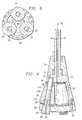
- FIG. 1is a front view of a first pipe burster in accordance with the invention
- FIG. 2is a side view of the pipe burster of FIG. 1;
- FIG. 3is a cross section of the pipe burster of FIG. 1 taken along line 3 — 3 in FIG. 2;
- FIG. 4is a lengthwise sectional view taken along the line 4 — 4 in FIG. 1;
- FIG. 5is a front view of a second pipe burster in accordance with the invention.
- FIG. 6is a side view of the pipe burster of FIG. 5;
- FIG. 7is a partial perspective view of the pipe burster of FIG. 5 with the frame removed;
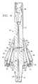
- FIG. 8is a lengthwise section of the pipe burster of FIG. 5 taken along line 8 — 8 of FIG. 5, and.
- FIG. 9is a partial lengthwise section of a second alternative embodiment of a burster according to the invention.
- an improved roller pipe burster 10 in accordance with the inventionincludes a burster frame 11 including a central shaft 12 and a frustoconical hollow shell 20 .
- Shaft 12is provided with a suitable coupling (not shown) for attaching burster 10 to a drill string and pulling and rotating the burster through a pipe to be burst.
- the couplingmay be any conventional connection used for connecting a drill string to a horizontal boring tool, or may be a splined connection such as disclosed in Wentworth et al. U.S. Pat. No. 6,148,935, issued Nov. 21, 2000 or Wentworth et al. PCT Publication WO 00/11303, published Mar. 2, 2000.
- a central fluid passage 16extends longitudinally through shaft 12 coincident with the axis of rotation 18 of burster 10 for providing pressurized water or a lubricant fluid during operation.
- a forwardly tapered head portion or nosecone 14is mounted on shaft 12 by bearings 15 so as to allow shaft 12 to rotate independently of head 14 .
- frustoconical hollow shell 20Positioned behind head 14 is frustoconical hollow shell 20 , which is integral with or rigidly connected to shaft 12 for rotation with shaft 12 .
- a plurality of frustoconical rollers 24are mounted on axles 26 by bearings 28 in spaced apart relationship inside the tapered shell 20 .
- the forward end of each axle 26is fitted into a rearwardly opening aperture 27 in shell 20 .
- a threaded head 25 at the rearward end of each axle 26is threaded into end plate 29 of burster 10 .
- End plate 29is fastened to shell 20 with a plurality of bolts 33 , securing axles 26 and rollers 24 in place.
- Axles 26 and rollers 24are preferably forwardly inclined relative to axis of rotation 18 , namely they are positioned at an acute included angle relative to axis of rotation 18 , with axles 26 extending inwardly towards axis 18 from back to front.
- the angle at which each axle 26 extendsmay vary, with angles in the range of 0 to 60 degrees, especially 10 to 45 degrees, being most effective for bursting pipes ranging in diameters from about 6 to 36 inches.
- the tapered outer surface of shell 20generally extends in parallel to axles 26 .
- burster 10is shown with three rollers 24 positioned symmetrically in tapered shell 20 , it will be appreciated that a greater or lesser number of rollers may be utilized, depending upon the specific application.
- rollers 24are preferably in lengthwise alignment with one another as shown, that is, the front and rear ends of each roller line up with the front and rear ends of the other rollers.
- Each roller 24is positioned adjacent to a longitudinally extending opening 30 with a portion 32 of the curved surface of the roller protruding from the opening. Preferably, less than half of the roller outer surface is exposed through the opening. Depending upon the desired clearance between the shell and the interior of the pipe, more or less of the roller outer surface may be exposed, generally between 5% and 40%, especially between 10% and 30%.
- rollers 24translate the rotational force applied to burster 10 through the drill string into axial forces concentrated on a relatively small contact area, thereby reducing the friction opposing rotation of the burster in the bore. Concentrating the axial force in this manner results in more efficient use of the power supplied to the burster through the drill string as compared to prior art reamers because less force is used to overcome friction and more axial force is applied per unit of surface area contacted.
- each roller 24engages the inside of the pipe directly and applies a bursting force.
- a rear portion 24 B of each roller 24engages the ground outside the pipe and also the fragments of the burst pipe, functioning to widen the hole and push the fragments outwardly.
- the drill string and shell 20are spinning at a substantially constant velocity. When a disk is spinning, the outermost rim moves fastest, with inner portions thereof moving slower because they travel less distance in the same unit of time.
- rollers 24The same problem arises for rollers 24 , in that the rear portion 24 B of each roller 24 must cover a greater distance in the same unit time as the mid-portion 24 A or front portion. During this travel, rear portion 24 B of roller 24 , if left free to rotate independently of midportion 24 A, would complete a greater number of revolutions about axle 26 than midportion 14 A. However, different speeds at different locations are not possible if roller 24 is unitary. As a result, roller 24 adopts a compromise speed of rotation about axle 26 , resulting in skidding of the rollers against the pipe or soil at the extreme front and rear positions. This skidding reduces the efficiency of the bursting operation.
- the amount of skidding that occurscan be reduced by using forwardly tapering rollers as shown to partially offset the effect of setting the rollers 24 at an angle relative to axis of rotation 18 .
- the front end of the roller 24 lying closest to the center of rotation of axle 26can cover less distance per unit time and still rotate in unison with the rear end of the roller 24 , which now lies further out due to the taper and must cover more distance in order to rotate once about axle 26 .
- the difference in the number of revolutions each portion of the rollerwould complete if separate from one another is reduced, and the amount of skidding of each roller 24 is reduced.
- Rollers 24are preferably smooth, without studs, teeth or similar projections, for the purpose of engaging the round inner wall of an existing pipeline. However, if desired rollers 24 may also have a roughened or knurled outer surface, or may be coated with a layer of carbide grit for greater wear resistance. To protect rollers 24 and shell 20 from ingress of abrasive materials, rollers 24 and openings 30 are sized and positioned relative to each other so that each opening 30 is only slightly greater than the protruding outer portion 32 of the roller, effectively hindering debris generated during the pipe bursting operation from entering the shell.
- Drilling fluid or water supplied through a passage 16 in shaft 12is injected into the interior of shell 20 and flows outwardly along the edges of each roller 24 , further hindering cuttings and dirt from entering shell 20 .
- the frameneed not comprise a hollow shell, and could for example be no more than one or several beams connecting to an end plate, leaving the area about the rollers wide open.
- Rollers 24may be lubricated with a heavy grease or similar lubricant supplied through T-shaped grease passages 34 through axles 26 .
- Each passage 34opens at the outer surface of axle 26 between the axle and roller at a location between seal bearings 28 , as illustrated in FIG. 3 .
- the inlet of each passage, located on axle head 25is plugged by a nut or the like except when grease is to be injected.
- Pipe burster 10 in accordance with this embodimentis suitable for bursting a variety of pipe types and sizes, including both frangible pipes such as clay or ceramic, and ductile pipes such as cast iron or steel.
- frangible pipessuch as clay or ceramic
- ductile pipessuch as cast iron or steel.
- cast iron and steel pipesespecially of diameters of 12 inches or more, are difficult to burst without first slitting the existing pipe.
- FIGS. 5-8illustrate a second embodiment of a pipe burster 50 which is specially adapted for bursting iron and steel pipes without slitting.
- Burster 50includes a central shaft 52 extending longitudinally through a frustoconical hollow shell 54 , an end plate 56 secured to the shell 54 with bolts 53 , and a plurality of tapered rollers 60 , each partially enclosed in shell 54 .
- six rollers 60are symmetrically (equiangularly) spaced around shell 54 with the small or narrow end of each roller angled inwardly toward the front of burster 50 .
- a protruding portion or surface 62 of each rollerextends through a lengthwise slot or hole 64 in shell 54 .
- a splined coupling 66of the type supplied by Earth Tool Company, L.L.C. of Oconomowoc, Wis.
- Splinelok®is threadedly coupled to a front end of shaft 52 for connecting burster 50 to the drill string.
- any convention coupling for attaching horizontal boring tools to a drill stringmay be used in place of splined coupling 66 .
- shell 54is mounted on central shaft 52 by a bearing 68 positioned in a nose 70 of the shell, allowing the shaft to turn independently of the shell, axles and end plate assembly as the drill string is rotated.
- Shaft 52extends through shell 54 and end plate 56 and includes a rear coupling end 57 to enable connection of a second burster or similar tool, or to a pullback swivel for towing a replacement pipe into place behind the burster as the burster makes its way through the ground.
- the pullback swivelknown in the art, prevents the replacement pipe from rotating with the pipe burster.
- the replacement pipemay have a diameter that is as great as the rear end of burster 50 (or 10 ) substantially greater than that of the pipe being replaced, an advantage not obtainable with various other pipe bursting methods.
- Shaft 52is also provided with a central fluid passage 72 with ports 76 that discharge drilling fluid into an annular chamber 78 inside shell 54 .
- Chamber 78communicates with the spaces between the rollers 60 inside shell 54 , allowing the drilling fluid to lubricate rollers 60 . Drilling fluid discharging into the interior of shell 54 also tends to pressurize the interior of the shell, retarding the ingress of debris around rollers 54 .
- a continuation passage 72 Acan be used to supply fluid to a second trailing pipe burster of larger size, or may be blocked off if end 57 is to be directly connected to a pipe pullback swivel.
- Front and rear O-ring seals 80are provided between shaft 50 and shell 54 , end plate 56 respectively to protect shell 54 and shaft 50 from ingress of abrasive materials.
- Shaft 50has a forwardly tapered section 84 extending the length of rollers 60 that widens from a narrow diameter end 88 proximate nose 70 of shell 54 to a wide diameter end 90 adjacent to the rearmost ends of rollers 60 .
- Wide diameter end 90 of tapered section 84is rotatably supported by a bearing 89 mounted rearwardly of rollers 60 in a frontwardly opening recess in end plate 56 .
- Rollers 60are each mounted on an axle 94 with front and rear seal bearings 96 .
- each axle 94is retained in a rearwardly opening aperture 100 in nose 70 of shell 54 , and the rear end of the axle 94 is threadedly secured in a corresponding threaded recess in end plate 56 , or secured by other suitable means, such a jam nut.
- Axles 94may be also be provided with grease passages for lubrication, similar to passage 34 shown in FIG. 3 .
- Axles 94are angled inwardly, towards the axis of rotation of burster 50 , with the forward end of each axle positioned closer to shaft 52 than the rearward end of the axle.
- the angle of each axle 94 , the taper of rollers 60 and the taper of tapered section 84 of shaft 52are configured so that the innermost tangential surface of each roller 60 contacts an outer tangential surface of tapered section 84 of shaft 52 . Consequently, as the drill string is rotated, shaft 52 turns against rollers 60 causing the rollers to rotate in the direction opposite the rotation of shaft 52 as the burster is drawn though a pipe.
- central shaft 52directly drives rollers 60 , which in turn cause shell 54 to rotate.
- central shaft 12rotates shell 20 , indirectly driving rollers 24 around the inner surface of the pipe.
- each roller 60 and its corresponding axle 94are aligned with the axis of rotation 99 , such that a radial line R bisects each roller 60 .
- additional thrust forcecan be generated by slightly skewing each axle 94 and roller 60 in a circumferential direction. This can be done, for example, by shifting the position of the rear end of each axle 94 up to about 5 degrees relative to radial line R, especially between about 0.5 to 5 degrees.
- Each axlewould then lie along a line R which is skewed relative to radial line R such that the leading end during rotation is the narrow end of each roller 60 .
- the contours of rollers 60 and tapered section 84are altered as need to maintain proper driving contact.
- tapered section 84 of shaft 52 and rollers 60 in burster 50provides an advantage that is particularly adaptable to pipe bursting applications for ductile, high strength pipes made of steel or cast iron.
- shaft 52 and tapered section 84are placed under tension. This causes tapered section 84 to exert an axial force against rollers 60 that tends to push the rollers outwardly against the pipe wall while simultaneously increasing the friction between tapered section 84 and rollers 60 , which reduces slippage between the shaft and the rollers.
- a longitudinal pulling force applied to the shaftis directly translated into an axial bursting force through rollers 60 , which contact the pipe wall over a limited surface area, concentrating the force.
- FIG. 9illustrates a further embodiment of the invention wherein a burster 100 of the invention includes a frame 101 in the form of a central shaft 102 and end plate 103 .
- the front end connecting portion 104is half of a standard API threaded connection, shown attached to a drill string 105 .
- Axles 106are threadedly mounted in holes 107 in end plate 103 and secured by round front end caps 108 and rear nuts 109 .
- axles 106are parallel to the axis of rotation of the frame (of shaft 102 ), and the curved surfaces that taper forwardly are supplied entirely by the taper of the individual rollers 111 .
- rollers corresponding to 111are cylindrical and the axles are inwardly tilted from rear to front as needed to maintain engagement with the cylindrical inner surface of a pipe 112 to be burst.
- a flow passage 113is provided to supply water or other lubricant as needed.
- a pipe burster according to the inventionhas advantages over known bursting systems that operate by reaming. Maintaining line and grade, critical considerations for replacing gravity sewer lines, are difficult using a reamer because cuttings sink to the bottom of the bore and create a mound that deflects the reamer upward. In the method of the invention, there are also no cuttings that need to float away (in the sewer line) and be disposed of. In addition, the lubricant introduced inside the shell not only discourages the small amount of spoil or loose material from entering inside, but also flushes the volume continuously and lubricates the replacement pipe as it is drawn along behind the burster, such as by a swivel connection as discussed above.
Landscapes
- Engineering & Computer Science (AREA)
- Life Sciences & Earth Sciences (AREA)
- Geology (AREA)
- Mining & Mineral Resources (AREA)
- Physics & Mathematics (AREA)
- Environmental & Geological Engineering (AREA)
- Fluid Mechanics (AREA)
- General Life Sciences & Earth Sciences (AREA)
- Geochemistry & Mineralogy (AREA)
- Mechanical Engineering (AREA)
- Earth Drilling (AREA)
- Excavating Of Shafts Or Tunnels (AREA)
Abstract
Description
Claims (22)
Priority Applications (1)
| Application Number | Priority Date | Filing Date | Title |
|---|---|---|---|
| US09/880,270US6568488B2 (en) | 2001-06-13 | 2001-06-13 | Roller pipe burster |
Applications Claiming Priority (1)
| Application Number | Priority Date | Filing Date | Title |
|---|---|---|---|
| US09/880,270US6568488B2 (en) | 2001-06-13 | 2001-06-13 | Roller pipe burster |
Publications (2)
| Publication Number | Publication Date |
|---|---|
| US20020189811A1 US20020189811A1 (en) | 2002-12-19 |
| US6568488B2true US6568488B2 (en) | 2003-05-27 |
Family
ID=25375907
Family Applications (1)
| Application Number | Title | Priority Date | Filing Date |
|---|---|---|---|
| US09/880,270Expired - Fee RelatedUS6568488B2 (en) | 2001-06-13 | 2001-06-13 | Roller pipe burster |
Country Status (1)
| Country | Link |
|---|---|
| US (1) | US6568488B2 (en) |
Cited By (61)
| Publication number | Priority date | Publication date | Assignee | Title |
|---|---|---|---|---|
| US20020189816A1 (en)* | 1998-12-07 | 2002-12-19 | Shell Oil Co. | Wellbore casing |
| US20040123983A1 (en)* | 1998-11-16 | 2004-07-01 | Enventure Global Technology L.L.C. | Isolation of subterranean zones |
| US20040123988A1 (en)* | 1998-12-07 | 2004-07-01 | Shell Oil Co. | Wellhead |
| US20040131426A1 (en)* | 2001-03-08 | 2004-07-08 | Franz-Josef Puttmann | Device for breaking up pipelines |
| US20040184088A1 (en)* | 1999-03-04 | 2004-09-23 | Panasonic Communications Co., Ltd. | Image data communication device and method |
| US20040188099A1 (en)* | 1998-12-07 | 2004-09-30 | Shell Oil Co. | Method of creating a casing in a borehole |
| US20050073196A1 (en)* | 2003-09-29 | 2005-04-07 | Yamaha Motor Co. Ltd. | Theft prevention system, theft prevention apparatus and power source controller for the system, transport vehicle including theft prevention system, and theft prevention method |
| US20050081358A1 (en)* | 1998-11-16 | 2005-04-21 | Cook Robert L. | Radial expansion of tubular members |
| US6976541B2 (en) | 2000-09-18 | 2005-12-20 | Shell Oil Company | Liner hanger with sliding sleeve valve |
| US7011161B2 (en) | 1998-12-07 | 2006-03-14 | Shell Oil Company | Structural support |
| US7048067B1 (en) | 1999-11-01 | 2006-05-23 | Shell Oil Company | Wellbore casing repair |
| US7055608B2 (en) | 1999-03-11 | 2006-06-06 | Shell Oil Company | Forming a wellbore casing while simultaneously drilling a wellbore |
| US20060157276A1 (en)* | 2003-08-08 | 2006-07-20 | Jim Carothers | Pipe burster with spherical bursting member |
| US7100685B2 (en) | 2000-10-02 | 2006-09-05 | Enventure Global Technology | Mono-diameter wellbore casing |
| US7100684B2 (en) | 2000-07-28 | 2006-09-05 | Enventure Global Technology | Liner hanger with standoffs |
| US7159667B2 (en) | 1999-02-25 | 2007-01-09 | Shell Oil Company | Method of coupling a tubular member to a preexisting structure |
| US7168496B2 (en) | 2001-07-06 | 2007-01-30 | Eventure Global Technology | Liner hanger |
| US7172024B2 (en) | 2000-10-02 | 2007-02-06 | Shell Oil Company | Mono-diameter wellbore casing |
| US7185710B2 (en) | 1998-12-07 | 2007-03-06 | Enventure Global Technology | Mono-diameter wellbore casing |
| US7195064B2 (en) | 1998-12-07 | 2007-03-27 | Enventure Global Technology | Mono-diameter wellbore casing |
| US7231985B2 (en) | 1998-11-16 | 2007-06-19 | Shell Oil Company | Radial expansion of tubular members |
| US7234531B2 (en) | 1999-12-03 | 2007-06-26 | Enventure Global Technology, Llc | Mono-diameter wellbore casing |
| US7240728B2 (en) | 1998-12-07 | 2007-07-10 | Shell Oil Company | Expandable tubulars with a radial passage and wall portions with different wall thicknesses |
| US7243731B2 (en) | 2001-08-20 | 2007-07-17 | Enventure Global Technology | Apparatus for radially expanding tubular members including a segmented expansion cone |
| US7258168B2 (en) | 2001-07-27 | 2007-08-21 | Enventure Global Technology L.L.C. | Liner hanger with slip joint sealing members and method of use |
| US7290605B2 (en) | 2001-12-27 | 2007-11-06 | Enventure Global Technology | Seal receptacle using expandable liner hanger |
| US7290616B2 (en) | 2001-07-06 | 2007-11-06 | Enventure Global Technology, L.L.C. | Liner hanger |
| US7308755B2 (en) | 2003-06-13 | 2007-12-18 | Shell Oil Company | Apparatus for forming a mono-diameter wellbore casing |
| US7325602B2 (en) | 2000-10-02 | 2008-02-05 | Shell Oil Company | Method and apparatus for forming a mono-diameter wellbore casing |
| US7350563B2 (en) | 1999-07-09 | 2008-04-01 | Enventure Global Technology, L.L.C. | System for lining a wellbore casing |
| US7353889B1 (en) | 2002-11-04 | 2008-04-08 | The Charles Machine Works, Inc. | Rotary driven pipe-bursting tool |
| US7360591B2 (en) | 2002-05-29 | 2008-04-22 | Enventure Global Technology, Llc | System for radially expanding a tubular member |
| US7363984B2 (en) | 1998-12-07 | 2008-04-29 | Enventure Global Technology, Llc | System for radially expanding a tubular member |
| US7377326B2 (en) | 2002-08-23 | 2008-05-27 | Enventure Global Technology, L.L.C. | Magnetic impulse applied sleeve method of forming a wellbore casing |
| US7383889B2 (en) | 2001-11-12 | 2008-06-10 | Enventure Global Technology, Llc | Mono diameter wellbore casing |
| US7398832B2 (en) | 2002-06-10 | 2008-07-15 | Enventure Global Technology, Llc | Mono-diameter wellbore casing |
| US7404444B2 (en) | 2002-09-20 | 2008-07-29 | Enventure Global Technology | Protective sleeve for expandable tubulars |
| US20080181727A1 (en)* | 2007-01-26 | 2008-07-31 | Crane Robert F | Method and apparatus for pipe reforming and clearing |
| US7410000B2 (en) | 2001-01-17 | 2008-08-12 | Enventure Global Technology, Llc. | Mono-diameter wellbore casing |
| US7416027B2 (en) | 2001-09-07 | 2008-08-26 | Enventure Global Technology, Llc | Adjustable expansion cone assembly |
| US7424918B2 (en) | 2002-08-23 | 2008-09-16 | Enventure Global Technology, L.L.C. | Interposed joint sealing layer method of forming a wellbore casing |
| US7438133B2 (en) | 2003-02-26 | 2008-10-21 | Enventure Global Technology, Llc | Apparatus and method for radially expanding and plastically deforming a tubular member |
| US7503393B2 (en) | 2003-01-27 | 2009-03-17 | Enventure Global Technology, Inc. | Lubrication system for radially expanding tubular members |
| US7513313B2 (en) | 2002-09-20 | 2009-04-07 | Enventure Global Technology, Llc | Bottom plug for forming a mono diameter wellbore casing |
| US7516790B2 (en) | 1999-12-03 | 2009-04-14 | Enventure Global Technology, Llc | Mono-diameter wellbore casing |
| US7552776B2 (en) | 1998-12-07 | 2009-06-30 | Enventure Global Technology, Llc | Anchor hangers |
| US7571774B2 (en) | 2002-09-20 | 2009-08-11 | Eventure Global Technology | Self-lubricating expansion mandrel for expandable tubular |
| US7603758B2 (en) | 1998-12-07 | 2009-10-20 | Shell Oil Company | Method of coupling a tubular member |
| US7712522B2 (en) | 2003-09-05 | 2010-05-11 | Enventure Global Technology, Llc | Expansion cone and system |
| US7740076B2 (en) | 2002-04-12 | 2010-06-22 | Enventure Global Technology, L.L.C. | Protective sleeve for threaded connections for expandable liner hanger |
| US7739917B2 (en) | 2002-09-20 | 2010-06-22 | Enventure Global Technology, Llc | Pipe formability evaluation for expandable tubulars |
| US7775290B2 (en) | 2003-04-17 | 2010-08-17 | Enventure Global Technology, Llc | Apparatus for radially expanding and plastically deforming a tubular member |
| US7793721B2 (en) | 2003-03-11 | 2010-09-14 | Eventure Global Technology, Llc | Apparatus for radially expanding and plastically deforming a tubular member |
| US7819185B2 (en) | 2004-08-13 | 2010-10-26 | Enventure Global Technology, Llc | Expandable tubular |
| US7886831B2 (en) | 2003-01-22 | 2011-02-15 | Enventure Global Technology, L.L.C. | Apparatus for radially expanding and plastically deforming a tubular member |
| US7918284B2 (en) | 2002-04-15 | 2011-04-05 | Enventure Global Technology, L.L.C. | Protective sleeve for threaded connections for expandable liner hanger |
| US20110079469A1 (en)* | 2009-10-05 | 2011-04-07 | Tt Technologies, Inc. | Lubrication system for pipe bursting |
| US20140041880A1 (en)* | 2012-08-07 | 2014-02-13 | Enventure Global Technology, Llc | Hybrid expansion cone |
| US20140294512A1 (en)* | 2013-04-01 | 2014-10-02 | Earth Tool Company Llc | Powered Slip Actuation |
| RU2620186C2 (en)* | 2014-07-10 | 2017-05-23 | Анатолий Степанович Громадский | Method of drilling compensation wells |
| US10161201B2 (en) | 2013-04-01 | 2018-12-25 | Earth Tool Company Llc | Powered slip actuation |
Families Citing this family (2)
| Publication number | Priority date | Publication date | Assignee | Title |
|---|---|---|---|---|
| US8225885B2 (en)* | 2008-05-01 | 2012-07-24 | Earth Tool Company, Llc | Joint for use in back reaming |
| CN109596021B (en)* | 2018-12-10 | 2021-04-09 | 贵州大学 | A blasting device with a directional blasting mechanism |
Citations (9)
| Publication number | Priority date | Publication date | Assignee | Title |
|---|---|---|---|---|
| US2809015A (en) | 1954-03-29 | 1957-10-08 | John T Phipps | Under reamer |
| US3945447A (en) | 1974-09-16 | 1976-03-23 | Rapidex, Inc. | Boring apparatus |
| US4031974A (en) | 1975-05-27 | 1977-06-28 | Rapidex, Inc. | Boring apparatus capable of boring straight holes |
| US4102416A (en)* | 1976-09-13 | 1978-07-25 | Foster-Miller Associates, Inc. | Stabilized conical boring tool |
| US4765417A (en)* | 1986-08-04 | 1988-08-23 | Oil Patch Group Inc. | Reaming apparatus for well drilling |
| US5076730A (en)* | 1991-04-23 | 1991-12-31 | Bergey Michael J | Earth duct tunnel enlargement apparatus and method |
| US5220964A (en) | 1991-09-23 | 1993-06-22 | The Charles Machine Works, Inc. | Downhole compaction and stabilization back reamer and drill bit |
| US5490569A (en) | 1994-03-22 | 1996-02-13 | The Charles Machine Works, Inc. | Directional boring head with deflection shoe and method of boring |
| US5607257A (en) | 1994-01-11 | 1997-03-04 | Brewis; Roderick C. | Drilling apparatus |
- 2001
- 2001-06-13USUS09/880,270patent/US6568488B2/ennot_activeExpired - Fee Related
Patent Citations (9)
| Publication number | Priority date | Publication date | Assignee | Title |
|---|---|---|---|---|
| US2809015A (en) | 1954-03-29 | 1957-10-08 | John T Phipps | Under reamer |
| US3945447A (en) | 1974-09-16 | 1976-03-23 | Rapidex, Inc. | Boring apparatus |
| US4031974A (en) | 1975-05-27 | 1977-06-28 | Rapidex, Inc. | Boring apparatus capable of boring straight holes |
| US4102416A (en)* | 1976-09-13 | 1978-07-25 | Foster-Miller Associates, Inc. | Stabilized conical boring tool |
| US4765417A (en)* | 1986-08-04 | 1988-08-23 | Oil Patch Group Inc. | Reaming apparatus for well drilling |
| US5076730A (en)* | 1991-04-23 | 1991-12-31 | Bergey Michael J | Earth duct tunnel enlargement apparatus and method |
| US5220964A (en) | 1991-09-23 | 1993-06-22 | The Charles Machine Works, Inc. | Downhole compaction and stabilization back reamer and drill bit |
| US5607257A (en) | 1994-01-11 | 1997-03-04 | Brewis; Roderick C. | Drilling apparatus |
| US5490569A (en) | 1994-03-22 | 1996-02-13 | The Charles Machine Works, Inc. | Directional boring head with deflection shoe and method of boring |
Non-Patent Citations (1)
| Title |
|---|
| Brochure for "Rock Mauler," Wenzel Downhole Tools Ltd. Trenchless Division, (pp. 2), (Not dated). |
Cited By (100)
| Publication number | Priority date | Publication date | Assignee | Title |
|---|---|---|---|---|
| US7121352B2 (en) | 1998-11-16 | 2006-10-17 | Enventure Global Technology | Isolation of subterranean zones |
| US7275601B2 (en) | 1998-11-16 | 2007-10-02 | Shell Oil Company | Radial expansion of tubular members |
| US20040123983A1 (en)* | 1998-11-16 | 2004-07-01 | Enventure Global Technology L.L.C. | Isolation of subterranean zones |
| US7270188B2 (en) | 1998-11-16 | 2007-09-18 | Shell Oil Company | Radial expansion of tubular members |
| US7246667B2 (en) | 1998-11-16 | 2007-07-24 | Shell Oil Company | Radial expansion of tubular members |
| US7357190B2 (en) | 1998-11-16 | 2008-04-15 | Shell Oil Company | Radial expansion of tubular members |
| US7231985B2 (en) | 1998-11-16 | 2007-06-19 | Shell Oil Company | Radial expansion of tubular members |
| US7299881B2 (en) | 1998-11-16 | 2007-11-27 | Shell Oil Company | Radial expansion of tubular members |
| US20050081358A1 (en)* | 1998-11-16 | 2005-04-21 | Cook Robert L. | Radial expansion of tubular members |
| US7216701B2 (en) | 1998-12-07 | 2007-05-15 | Shell Oil Company | Apparatus for expanding a tubular member |
| US20040188099A1 (en)* | 1998-12-07 | 2004-09-30 | Shell Oil Co. | Method of creating a casing in a borehole |
| US7021390B2 (en) | 1998-12-07 | 2006-04-04 | Shell Oil Company | Tubular liner for wellbore casing |
| US7350564B2 (en) | 1998-12-07 | 2008-04-01 | Enventure Global Technology, L.L.C. | Mono-diameter wellbore casing |
| US20030056949A1 (en)* | 1998-12-07 | 2003-03-27 | Shell Oil Co. | Wellbore casing |
| US7077211B2 (en) | 1998-12-07 | 2006-07-18 | Shell Oil Company | Method of creating a casing in a borehole |
| US20040123988A1 (en)* | 1998-12-07 | 2004-07-01 | Shell Oil Co. | Wellhead |
| US7552776B2 (en) | 1998-12-07 | 2009-06-30 | Enventure Global Technology, Llc | Anchor hangers |
| US7357188B1 (en) | 1998-12-07 | 2008-04-15 | Shell Oil Company | Mono-diameter wellbore casing |
| US7108061B2 (en) | 1998-12-07 | 2006-09-19 | Shell Oil Company | Expander for a tapered liner with a shoe |
| US7665532B2 (en) | 1998-12-07 | 2010-02-23 | Shell Oil Company | Pipeline |
| US7121337B2 (en) | 1998-12-07 | 2006-10-17 | Shell Oil Company | Apparatus for expanding a tubular member |
| US7147053B2 (en) | 1998-12-07 | 2006-12-12 | Shell Oil Company | Wellhead |
| US7240729B2 (en) | 1998-12-07 | 2007-07-10 | Shell Oil Company | Apparatus for expanding a tubular member |
| US7240728B2 (en) | 1998-12-07 | 2007-07-10 | Shell Oil Company | Expandable tubulars with a radial passage and wall portions with different wall thicknesses |
| US7159665B2 (en) | 1998-12-07 | 2007-01-09 | Shell Oil Company | Wellbore casing |
| US7011161B2 (en) | 1998-12-07 | 2006-03-14 | Shell Oil Company | Structural support |
| US20020189816A1 (en)* | 1998-12-07 | 2002-12-19 | Shell Oil Co. | Wellbore casing |
| US7603758B2 (en) | 1998-12-07 | 2009-10-20 | Shell Oil Company | Method of coupling a tubular member |
| US7434618B2 (en) | 1998-12-07 | 2008-10-14 | Shell Oil Company | Apparatus for expanding a tubular member |
| US7174964B2 (en) | 1998-12-07 | 2007-02-13 | Shell Oil Company | Wellhead with radially expanded tubulars |
| US7185710B2 (en) | 1998-12-07 | 2007-03-06 | Enventure Global Technology | Mono-diameter wellbore casing |
| US7195061B2 (en) | 1998-12-07 | 2007-03-27 | Shell Oil Company | Apparatus for expanding a tubular member |
| US7195064B2 (en) | 1998-12-07 | 2007-03-27 | Enventure Global Technology | Mono-diameter wellbore casing |
| US7198100B2 (en) | 1998-12-07 | 2007-04-03 | Shell Oil Company | Apparatus for expanding a tubular member |
| US7419009B2 (en) | 1998-12-07 | 2008-09-02 | Shell Oil Company | Apparatus for radially expanding and plastically deforming a tubular member |
| US7363984B2 (en) | 1998-12-07 | 2008-04-29 | Enventure Global Technology, Llc | System for radially expanding a tubular member |
| US7159667B2 (en) | 1999-02-25 | 2007-01-09 | Shell Oil Company | Method of coupling a tubular member to a preexisting structure |
| US7556092B2 (en) | 1999-02-26 | 2009-07-07 | Enventure Global Technology, Llc | Flow control system for an apparatus for radially expanding tubular members |
| US20040184088A1 (en)* | 1999-03-04 | 2004-09-23 | Panasonic Communications Co., Ltd. | Image data communication device and method |
| US7438132B2 (en) | 1999-03-11 | 2008-10-21 | Shell Oil Company | Concentric pipes expanded at the pipe ends and method of forming |
| US7055608B2 (en) | 1999-03-11 | 2006-06-06 | Shell Oil Company | Forming a wellbore casing while simultaneously drilling a wellbore |
| US7350563B2 (en) | 1999-07-09 | 2008-04-01 | Enventure Global Technology, L.L.C. | System for lining a wellbore casing |
| US7048067B1 (en) | 1999-11-01 | 2006-05-23 | Shell Oil Company | Wellbore casing repair |
| US7234531B2 (en) | 1999-12-03 | 2007-06-26 | Enventure Global Technology, Llc | Mono-diameter wellbore casing |
| US7516790B2 (en) | 1999-12-03 | 2009-04-14 | Enventure Global Technology, Llc | Mono-diameter wellbore casing |
| US7100684B2 (en) | 2000-07-28 | 2006-09-05 | Enventure Global Technology | Liner hanger with standoffs |
| US7172021B2 (en) | 2000-09-18 | 2007-02-06 | Shell Oil Company | Liner hanger with sliding sleeve valve |
| US6976541B2 (en) | 2000-09-18 | 2005-12-20 | Shell Oil Company | Liner hanger with sliding sleeve valve |
| US7172024B2 (en) | 2000-10-02 | 2007-02-06 | Shell Oil Company | Mono-diameter wellbore casing |
| US7146702B2 (en) | 2000-10-02 | 2006-12-12 | Shell Oil Company | Method and apparatus for forming a mono-diameter wellbore casing |
| US7325602B2 (en) | 2000-10-02 | 2008-02-05 | Shell Oil Company | Method and apparatus for forming a mono-diameter wellbore casing |
| US7201223B2 (en) | 2000-10-02 | 2007-04-10 | Shell Oil Company | Method and apparatus for forming a mono-diameter wellbore casing |
| US7100685B2 (en) | 2000-10-02 | 2006-09-05 | Enventure Global Technology | Mono-diameter wellbore casing |
| US7363690B2 (en) | 2000-10-02 | 2008-04-29 | Shell Oil Company | Method and apparatus for forming a mono-diameter wellbore casing |
| US7363691B2 (en) | 2000-10-02 | 2008-04-29 | Shell Oil Company | Method and apparatus for forming a mono-diameter wellbore casing |
| US7204007B2 (en) | 2000-10-02 | 2007-04-17 | Shell Oil Company | Method and apparatus for forming a mono-diameter wellbore casing |
| US7172019B2 (en) | 2000-10-02 | 2007-02-06 | Shell Oil Company | Method and apparatus for forming a mono-diameter wellbore casing |
| US7410000B2 (en) | 2001-01-17 | 2008-08-12 | Enventure Global Technology, Llc. | Mono-diameter wellbore casing |
| US20040131426A1 (en)* | 2001-03-08 | 2004-07-08 | Franz-Josef Puttmann | Device for breaking up pipelines |
| US7168496B2 (en) | 2001-07-06 | 2007-01-30 | Eventure Global Technology | Liner hanger |
| US7290616B2 (en) | 2001-07-06 | 2007-11-06 | Enventure Global Technology, L.L.C. | Liner hanger |
| US7258168B2 (en) | 2001-07-27 | 2007-08-21 | Enventure Global Technology L.L.C. | Liner hanger with slip joint sealing members and method of use |
| US7243731B2 (en) | 2001-08-20 | 2007-07-17 | Enventure Global Technology | Apparatus for radially expanding tubular members including a segmented expansion cone |
| US7416027B2 (en) | 2001-09-07 | 2008-08-26 | Enventure Global Technology, Llc | Adjustable expansion cone assembly |
| US7383889B2 (en) | 2001-11-12 | 2008-06-10 | Enventure Global Technology, Llc | Mono diameter wellbore casing |
| US7559365B2 (en) | 2001-11-12 | 2009-07-14 | Enventure Global Technology, Llc | Collapsible expansion cone |
| US7290605B2 (en) | 2001-12-27 | 2007-11-06 | Enventure Global Technology | Seal receptacle using expandable liner hanger |
| US7740076B2 (en) | 2002-04-12 | 2010-06-22 | Enventure Global Technology, L.L.C. | Protective sleeve for threaded connections for expandable liner hanger |
| US7918284B2 (en) | 2002-04-15 | 2011-04-05 | Enventure Global Technology, L.L.C. | Protective sleeve for threaded connections for expandable liner hanger |
| US7360591B2 (en) | 2002-05-29 | 2008-04-22 | Enventure Global Technology, Llc | System for radially expanding a tubular member |
| US7398832B2 (en) | 2002-06-10 | 2008-07-15 | Enventure Global Technology, Llc | Mono-diameter wellbore casing |
| US7377326B2 (en) | 2002-08-23 | 2008-05-27 | Enventure Global Technology, L.L.C. | Magnetic impulse applied sleeve method of forming a wellbore casing |
| US7424918B2 (en) | 2002-08-23 | 2008-09-16 | Enventure Global Technology, L.L.C. | Interposed joint sealing layer method of forming a wellbore casing |
| US7513313B2 (en) | 2002-09-20 | 2009-04-07 | Enventure Global Technology, Llc | Bottom plug for forming a mono diameter wellbore casing |
| US7571774B2 (en) | 2002-09-20 | 2009-08-11 | Eventure Global Technology | Self-lubricating expansion mandrel for expandable tubular |
| US7404444B2 (en) | 2002-09-20 | 2008-07-29 | Enventure Global Technology | Protective sleeve for expandable tubulars |
| US7739917B2 (en) | 2002-09-20 | 2010-06-22 | Enventure Global Technology, Llc | Pipe formability evaluation for expandable tubulars |
| US7353889B1 (en) | 2002-11-04 | 2008-04-08 | The Charles Machine Works, Inc. | Rotary driven pipe-bursting tool |
| US7886831B2 (en) | 2003-01-22 | 2011-02-15 | Enventure Global Technology, L.L.C. | Apparatus for radially expanding and plastically deforming a tubular member |
| US7503393B2 (en) | 2003-01-27 | 2009-03-17 | Enventure Global Technology, Inc. | Lubrication system for radially expanding tubular members |
| US7438133B2 (en) | 2003-02-26 | 2008-10-21 | Enventure Global Technology, Llc | Apparatus and method for radially expanding and plastically deforming a tubular member |
| US7793721B2 (en) | 2003-03-11 | 2010-09-14 | Eventure Global Technology, Llc | Apparatus for radially expanding and plastically deforming a tubular member |
| US7775290B2 (en) | 2003-04-17 | 2010-08-17 | Enventure Global Technology, Llc | Apparatus for radially expanding and plastically deforming a tubular member |
| US7308755B2 (en) | 2003-06-13 | 2007-12-18 | Shell Oil Company | Apparatus for forming a mono-diameter wellbore casing |
| US20060157276A1 (en)* | 2003-08-08 | 2006-07-20 | Jim Carothers | Pipe burster with spherical bursting member |
| US7712522B2 (en) | 2003-09-05 | 2010-05-11 | Enventure Global Technology, Llc | Expansion cone and system |
| US20050073196A1 (en)* | 2003-09-29 | 2005-04-07 | Yamaha Motor Co. Ltd. | Theft prevention system, theft prevention apparatus and power source controller for the system, transport vehicle including theft prevention system, and theft prevention method |
| US7819185B2 (en) | 2004-08-13 | 2010-10-26 | Enventure Global Technology, Llc | Expandable tubular |
| US20080181727A1 (en)* | 2007-01-26 | 2008-07-31 | Crane Robert F | Method and apparatus for pipe reforming and clearing |
| US7559722B2 (en)* | 2007-01-26 | 2009-07-14 | Earth Tool Company, L.L.C. | Method and apparatus for pipe reforming and clearing |
| US9334999B2 (en)* | 2009-10-05 | 2016-05-10 | Tt Technologies, Inc. | Lubrication system for pipe bursting |
| US20110079469A1 (en)* | 2009-10-05 | 2011-04-07 | Tt Technologies, Inc. | Lubrication system for pipe bursting |
| US10119645B2 (en) | 2009-10-05 | 2018-11-06 | Tt Technologies, Inc. | Lubrication system for pipe bursting |
| US11209111B2 (en) | 2009-10-05 | 2021-12-28 | Tt Technologies, Inc. | Lubrication system for pipe bursting |
| US11578830B2 (en) | 2009-10-05 | 2023-02-14 | Tt Technologies, Inc. | Lubrication system for pipe bursting |
| US12247688B2 (en) | 2009-10-05 | 2025-03-11 | Tt Technologies, Inc. | Lubrication system for pipe bursting |
| US20140041880A1 (en)* | 2012-08-07 | 2014-02-13 | Enventure Global Technology, Llc | Hybrid expansion cone |
| US20140294512A1 (en)* | 2013-04-01 | 2014-10-02 | Earth Tool Company Llc | Powered Slip Actuation |
| US10161201B2 (en) | 2013-04-01 | 2018-12-25 | Earth Tool Company Llc | Powered slip actuation |
| RU2620186C2 (en)* | 2014-07-10 | 2017-05-23 | Анатолий Степанович Громадский | Method of drilling compensation wells |
Also Published As
| Publication number | Publication date |
|---|---|
| US20020189811A1 (en) | 2002-12-19 |
Similar Documents
| Publication | Publication Date | Title |
|---|---|---|
| US6568488B2 (en) | Roller pipe burster | |
| US5314267A (en) | Horizontal pipeline boring apparatus and method | |
| US5979574A (en) | Horizontal boring apparatus and method of using the same | |
| US7086808B2 (en) | Method and apparatus for on-grade boring | |
| EP1285145B1 (en) | Apparatus for directional drilling | |
| US7243737B2 (en) | Interchangeable reamer | |
| US7703551B2 (en) | Fluid driven drilling motor and system | |
| EP1339939B1 (en) | A drilling tool used in horizontal drilling applications | |
| US5456552A (en) | Method and apparatus for installing pipe in horizontal borehole | |
| AU2001265171A1 (en) | Apparatus for directional drilling | |
| US6761233B1 (en) | Apparatus for propulsion in elongated cavities | |
| CN103189590B (en) | Underground reaming machine | |
| AU1663301A (en) | Bit for directional drilling | |
| US11708726B2 (en) | Horizontal directional reaming | |
| US20010009633A1 (en) | Device for connecting a towed pipe to a towing apparatus | |
| US7730969B2 (en) | Reamer and methods for directional drilling | |
| US6698535B1 (en) | Floating offset transmitter housing underground directional drilling tool | |
| US9290993B2 (en) | Method and system for installation of in-ground conduit | |
| KR100335245B1 (en) | Tunneling machines having a means for removing of a crushed material at lower | |
| CN113006703A (en) | Wear-resistant PDC-roller composite drill bit | |
| US20250215751A1 (en) | Bearing assembly with flow restrictor for a dual rod directional drilling apparatus and method of use | |
| FI98649B (en) | Process for drilling a hole and device for realizing the process | |
| CA3201531C (en) | Horizontal directional reaming | |
| JPS58173294A (en) | Excavator | |
| US20160340981A1 (en) | Eccentric cones for rock cutting |
Legal Events
| Date | Code | Title | Description |
|---|---|---|---|
| AS | Assignment | Owner name:EARTH TOOL COMPANY, LLC, WISCONSIN Free format text:ASSIGNMENT OF ASSIGNORS INTEREST;ASSIGNORS:WENTWORTH, STEVEN W.;CRANE, ROBERT F.;HAU, PAUL W.;REEL/FRAME:011907/0908 Effective date:20010612 | |
| AS | Assignment | Owner name:MFC CAPITAL FUNDING, INC., ILLINOIS Free format text:SECURITY AGREEMENT;ASSIGNOR:EARTH TOOL COMPANY LLC;REEL/FRAME:017730/0384 Effective date:20060531 | |
| FPAY | Fee payment | Year of fee payment:4 | |
| FEPP | Fee payment procedure | Free format text:PAYOR NUMBER ASSIGNED (ORIGINAL EVENT CODE: ASPN); ENTITY STATUS OF PATENT OWNER: LARGE ENTITY | |
| AS | Assignment | Owner name:EARTH TOOL COMPANY LLC,WISCONSIN Free format text:RELEASE BY SECURED PARTY;ASSIGNOR:MFC CAPITAL FUNDING, INC.;REEL/FRAME:024218/0989 Effective date:20100409 | |
| FPAY | Fee payment | Year of fee payment:8 | |
| FEPP | Fee payment procedure | Free format text:PAT HOLDER NO LONGER CLAIMS SMALL ENTITY STATUS, ENTITY STATUS SET TO UNDISCOUNTED (ORIGINAL EVENT CODE: STOL); ENTITY STATUS OF PATENT OWNER: LARGE ENTITY | |
| REMI | Maintenance fee reminder mailed | ||
| LAPS | Lapse for failure to pay maintenance fees | ||
| STCH | Information on status: patent discontinuation | Free format text:PATENT EXPIRED DUE TO NONPAYMENT OF MAINTENANCE FEES UNDER 37 CFR 1.362 | |
| FP | Lapsed due to failure to pay maintenance fee | Effective date:20150527 |