US6566147B2 - Method for controlling deposition of dielectric films - Google Patents
Method for controlling deposition of dielectric filmsDownload PDFInfo
- Publication number
- US6566147B2 US6566147B2US09/776,217US77621701AUS6566147B2US 6566147 B2US6566147 B2US 6566147B2US 77621701 AUS77621701 AUS 77621701AUS 6566147 B2US6566147 B2US 6566147B2
- Authority
- US
- United States
- Prior art keywords
- strontium
- barium
- deposition chamber
- organometallic precursor
- film
- Prior art date
- Legal status (The legal status is an assumption and is not a legal conclusion. Google has not performed a legal analysis and makes no representation as to the accuracy of the status listed.)
- Expired - Lifetime
Links
Images


Classifications
- H—ELECTRICITY
- H01—ELECTRIC ELEMENTS
- H01L—SEMICONDUCTOR DEVICES NOT COVERED BY CLASS H10
- H01L21/00—Processes or apparatus adapted for the manufacture or treatment of semiconductor or solid state devices or of parts thereof
- H01L21/02—Manufacture or treatment of semiconductor devices or of parts thereof
- H01L21/02104—Forming layers
- H01L21/02107—Forming insulating materials on a substrate
- H01L21/02225—Forming insulating materials on a substrate characterised by the process for the formation of the insulating layer
- H01L21/0226—Forming insulating materials on a substrate characterised by the process for the formation of the insulating layer formation by a deposition process
- H01L21/02263—Forming insulating materials on a substrate characterised by the process for the formation of the insulating layer formation by a deposition process deposition from the gas or vapour phase
- H01L21/02271—Forming insulating materials on a substrate characterised by the process for the formation of the insulating layer formation by a deposition process deposition from the gas or vapour phase deposition by decomposition or reaction of gaseous or vapour phase compounds, i.e. chemical vapour deposition
- C—CHEMISTRY; METALLURGY
- C23—COATING METALLIC MATERIAL; COATING MATERIAL WITH METALLIC MATERIAL; CHEMICAL SURFACE TREATMENT; DIFFUSION TREATMENT OF METALLIC MATERIAL; COATING BY VACUUM EVAPORATION, BY SPUTTERING, BY ION IMPLANTATION OR BY CHEMICAL VAPOUR DEPOSITION, IN GENERAL; INHIBITING CORROSION OF METALLIC MATERIAL OR INCRUSTATION IN GENERAL
- C23C—COATING METALLIC MATERIAL; COATING MATERIAL WITH METALLIC MATERIAL; SURFACE TREATMENT OF METALLIC MATERIAL BY DIFFUSION INTO THE SURFACE, BY CHEMICAL CONVERSION OR SUBSTITUTION; COATING BY VACUUM EVAPORATION, BY SPUTTERING, BY ION IMPLANTATION OR BY CHEMICAL VAPOUR DEPOSITION, IN GENERAL
- C23C16/00—Chemical coating by decomposition of gaseous compounds, without leaving reaction products of surface material in the coating, i.e. chemical vapour deposition [CVD] processes
- C23C16/22—Chemical coating by decomposition of gaseous compounds, without leaving reaction products of surface material in the coating, i.e. chemical vapour deposition [CVD] processes characterised by the deposition of inorganic material, other than metallic material
- C23C16/30—Deposition of compounds, mixtures or solid solutions, e.g. borides, carbides, nitrides
- C23C16/40—Oxides
- C23C16/409—Oxides of the type ABO3 with A representing alkali, alkaline earth metal or lead and B representing a refractory metal, nickel, scandium or a lanthanide
- C—CHEMISTRY; METALLURGY
- C23—COATING METALLIC MATERIAL; COATING MATERIAL WITH METALLIC MATERIAL; CHEMICAL SURFACE TREATMENT; DIFFUSION TREATMENT OF METALLIC MATERIAL; COATING BY VACUUM EVAPORATION, BY SPUTTERING, BY ION IMPLANTATION OR BY CHEMICAL VAPOUR DEPOSITION, IN GENERAL; INHIBITING CORROSION OF METALLIC MATERIAL OR INCRUSTATION IN GENERAL
- C23C—COATING METALLIC MATERIAL; COATING MATERIAL WITH METALLIC MATERIAL; SURFACE TREATMENT OF METALLIC MATERIAL BY DIFFUSION INTO THE SURFACE, BY CHEMICAL CONVERSION OR SUBSTITUTION; COATING BY VACUUM EVAPORATION, BY SPUTTERING, BY ION IMPLANTATION OR BY CHEMICAL VAPOUR DEPOSITION, IN GENERAL
- C23C16/00—Chemical coating by decomposition of gaseous compounds, without leaving reaction products of surface material in the coating, i.e. chemical vapour deposition [CVD] processes
- C23C16/44—Chemical coating by decomposition of gaseous compounds, without leaving reaction products of surface material in the coating, i.e. chemical vapour deposition [CVD] processes characterised by the method of coating
- C23C16/52—Controlling or regulating the coating process
- H—ELECTRICITY
- H01—ELECTRIC ELEMENTS
- H01L—SEMICONDUCTOR DEVICES NOT COVERED BY CLASS H10
- H01L21/00—Processes or apparatus adapted for the manufacture or treatment of semiconductor or solid state devices or of parts thereof
- H01L21/02—Manufacture or treatment of semiconductor devices or of parts thereof
- H01L21/02104—Forming layers
- H01L21/02107—Forming insulating materials on a substrate
- H01L21/02109—Forming insulating materials on a substrate characterised by the type of layer, e.g. type of material, porous/non-porous, pre-cursors, mixtures or laminates
- H01L21/02112—Forming insulating materials on a substrate characterised by the type of layer, e.g. type of material, porous/non-porous, pre-cursors, mixtures or laminates characterised by the material of the layer
- H01L21/02172—Forming insulating materials on a substrate characterised by the type of layer, e.g. type of material, porous/non-porous, pre-cursors, mixtures or laminates characterised by the material of the layer the material containing at least one metal element, e.g. metal oxides, metal nitrides, metal oxynitrides or metal carbides
- H01L21/02197—Forming insulating materials on a substrate characterised by the type of layer, e.g. type of material, porous/non-porous, pre-cursors, mixtures or laminates characterised by the material of the layer the material containing at least one metal element, e.g. metal oxides, metal nitrides, metal oxynitrides or metal carbides the material having a perovskite structure, e.g. BaTiO3
Definitions
- the present inventionrelates to the preparation of semiconductor device structures. More particularly, the present invention pertains to methods of forming high dielectric constant films, such as barium-strontium-titanate films.
- dielectric filmshave been formed in the past during the fabrication of semiconductor devices.
- filmssuch as silicon dioxide and silicon nitride have been used for dielectric films in the formation of capacitors, such as for memory devices including, for example, dynamic random access memories (DRAMs).
- DRAMsdynamic random access memories
- One way of increasing cell capacitanceis through the use of different cell structures such as trench and/or stacked capacitors.
- feature sizecontinues to become smaller and smaller, development of improved materials for cell dielectrics, as well as the cell structure, have become important.
- dielectricssuch as silicon dioxide and silicon nitride may no longer be suitable for use in many devices because of their relatively small dielectric constants.
- Insulating inorganic metal oxide materialse.g., ferroelectric materials and perovskite oxides, have gained interest for use as dielectrics in memory devices.
- ferroelectric materials and perovskite oxideshave gained interest for use as dielectrics in memory devices.
- these materialshave high dielectric constants which make them attractive as dielectric materials in capacitors, for example, for high density DRAMs and other memory devices.
- a high dielectric constantrefers to a dielectric constant of about 15 or greater.
- such high dielectric constant materialsinclude tantalum pentoxide (Ta 2 O 5 ), barium-strontium-titanate (BST), strontium titanate (SrTiO 3 ), barium titanate (BaTiO 3 ), lead zirconium titanate (PZT), and strontium-bismuth-tantalate (SBT).
- Ta 2 O 5tantalum pentoxide
- BSTbarium-strontium-titanate
- strontium titanateSrTiO 3
- barium titanateBaTiO 3
- PZTlead zirconium titanate
- SBTstrontium-bismuth-tantalate
- the dielectric properties of such filmsare dependent on various film characteristics, such as the concentration of the components thereof, e.g., the concentration of titanium in a BST film.
- certain high dielectric constant materialshave better current leakage characteristics in capacitors than other high dielectric constant materials.
- aspects of the high dielectric constant materialmight be modified or tailored to achieve a particularly high dielectric constant, which may unfortunately and undesirably also tend to hurt the leakage characteristics, e.g., increased leakage current.
- metal oxides having multiple different metals bonded with oxygensuch as BST, PZT, and SBT, it is found that increasing titanium concentration of the components thereof results in different dielectric characteristics.
- incorporation efficiency of components in the filmare affected.
- incorporation efficiency of titanium in the formation of such high dielectric constant filmsdecreases in conventional low deposition temperature processes.
- the stoichiometry of the high dielectric constant filmsappear to be self-adjusting in low deposition temperature processes.
- changing precursor flow ratiosdoes not affect film composition at lower deposition temperatures, unlike the significant effect such changing of precursor flow ratios has in high temperature CVD processes.
- a change in precursor flow ratioe.g., Ba/Sr to Ti ratio
- a high dielectric constant filmin other words, for example, changing the stoichiometry of different layers or portions of a BST film as it is deposited
- low deposition temperature CVD processessince film composition is not affected by the conventional method of changing precursor flows, new methods of controlling the stoichiometry of high dielectric constant films are needed. Further, even if a film's stoichiometry is controlled to a certain degree by changing precursor flow, the control of stoichiometry by changing precursor flow is disadvantageous in that, for example, extensive time for conditioning is required to change such flows.
- the present inventionprovides the ability to control stoichiometry of dielectric films, e.g., high dielectric constant BST films, preferably at low deposition temperatures.
- a deposition process according to the present inventionmay use an adjustment in oxidizer flow and/or partial pressure, the provision of a hydrogen-containing component, an adjustment in hydrogen-containing component flow and/or partial pressure, an adjustment in deposition pressure, and/or a modification of system component parameters (e.g., heating a shower head or adjusting a distance between a shower head of the deposition system and a wafer upon which the film is to be deposited), to control the high dielectric constant film characteristics, e.g., film stoichiometry.
- system component parameterse.g., heating a shower head or adjusting a distance between a shower head of the deposition system and a wafer upon which the film is to be deposited
- a method for depositing a film according to the present inventionincludes providing a substrate assembly having a surface in a deposition chamber, preferably at a temperature less than 680° C.
- a barium-containing organometallic precursor, a strontium-containing organometallic precursor, a titanium-containing organometallic precursor, and optionally at least one oxidizer and at least one hydrogen-containing compositionare provided to the deposition chamber.
- a barium-strontium-titanate filmis formed on at least a portion of the surface using the barium-containing organometallic precursor, the strontium-containing organometallic precursor, the titanium-containing organometallic precursor, and optionally the at least one oxidizer and/or the at least one hydrogen-containing composition provided to the deposition chamber.
- the barium-strontium-titanate film formedincludes at least a first layer of the barium-strontium-titanate film having a first composition and at least a second layer of the barium-strontium-titanate film having a second composition.
- the formation of the filmis controlled in one or more various manners.
- the deposition processmay be controlled by adjusting the flow rate of the at least one oxidizer to the deposition chamber and/or a partial pressure of the at least one oxidizer in the deposition chamber during formation of the barium-strontium-titanate film such that composition of the barium-strontium-titanate film is adjusted from the first composition to the second composition.
- the oxidizer provided to the deposition chambermay be at least one of O 2 , O 3 , N 2 O, NO, SO 3 , H 2 O 2 , R 2 O 2 , where R is selected from a group consisting of a saturated or unsaturated linear, branched, or cyclic hydrocarbon group having about 1 carbon atom to about 20 carbon atoms, preferably about 2 carbon atoms to about 12 carbon atoms, for example, methyl, ethyl, isopropyl, t-butyl, heptyl, dodecyl, octadecyl, amyl, 2-ethythexyl, and the like.
- the deposition processmay be controlled by adjusting a deposition pressure of the deposition chamber during formation of the barium-strontium-titanate film.
- the deposition chambermay include a delivery device having a delivery outlet region.
- the deposition processmay then be controlled by adjusting a distance between the delivery outlet region of the delivery device and the surface of the substrate assembly during formation of the barium-strontium-titanate film and/or by adjusting a temperature of at least the delivery outlet region of the delivery device during formation of the barium-strontium-titanate film;
- the depoisition processmay be controlled by adjusting the flow rate of the at least one hydrogen-containing composition provided to the deposition chamber and/or a partial pressure of the at least one hydrogen-containing composition in the deposition chamber during formation of the barium-strontium-titanate film.
- the hydrogen-containing compositionmay include one or more of H 2 , NH 3 , N 2 H 4 , N 2 H 3 (CH 3 ), and H 2 O.
- Such adjustments to the processmay be performed while maintaining a flow rate of the barium-containing organometallic precursor, strontium-containing organometallic precursor, and the titanium-containing organometallic precursor provided to the deposition chamber.
- the first layer of the barium-strontium-titanate filmis an interfacial layer and the second layer of the barium-strontium-titanate film is a bulk layer.
- the interfacial layerhas an atomic percent of titanium less than or equal to the atomic percent of titanium in the bulk layer of the barium-strontium-titanate film.
- the adjusting of the deposition pressure of the deposition chamber during formation of the barium-strontium-titanate film while a flow rate of the barium-containing 6 organometallic precursor, the strontium-containing organometallic precursor, and the titanium-containing organometallic precursor to the deposition chamber is maintainedis such that composition of the barium-strontium-titanate film is adjusted from the first composition to the second composition. Further, with an increase in deposition pressure, an increase in percent titanium in the barium-strontium-titanate film and also an increase in a rate of deposition of the barium-strontium-titanate film can be attained.
- the deposition processes described abovemay be used to form a barium-strontium-titanate dielectric film for use in formation of a capacitor.
- a first electrode having a surface in a deposition chamberis provided, a barium-strontium-titanate dielectric film is formed on at least a portion of the surface of the first electrode, and thereafter, a second electrode is formed on at least a portion of the barium-strontium-titanate dielectric film.
- a substrate assembly having a surfacemay be provided in a deposition chamber at a temperature less than 680° C.
- a plurality of precursors including A and B and an oxidizer (and optionally, at least one hydrogen-containing composition)are provided to the deposition chamber having the substrate assembly positioned therein to deposit a film of ABO 3 on at least a portion of the surface of the substrate assembly.
- One or more of the control techniques described abovemay be used during deposition of the ABO 3 film to produce different concentrations of one of A and B at different elevations in the ABO 3 film.
- the different concentrationsinclude a concentration in a first layer of the ABO 3 film that is different from a concentration of a second layer of the ABO 3 film and/or the different concentrations are a gradient in concentrations in at least a portion of the ABO 3 film.
- FIG. 1is a cross-sectional schematic of a structure including a high dielectric constant film formed in accordance with the present invention.
- FIG. 2is a cross-sectional schematic of one embodiment of a capacitor structure including a high dielectric constant film formed in accordance with the present invention.
- FIG. 3is a schematic diagram of an exemplary system useable in accordance with the present invention in formation of an exemplary high dielectric constant film.
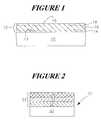
- FIG. 4is a graphical representation of the control of barium and strontium in a BST film according to one exemplary embodiment of the present invention.
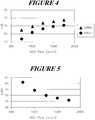
- FIG. 5is a graphical representation of the control of titanium in a BST film according to one exemplary embodiment of the present invention.
- the present inventionprovides the ability to control stoichiometry in high dielectric constant films, for example, a high dielectric constant film such as a (Ba,Sr)TiO 3 (barium-strontium-titanate or BST) film.
- a high dielectric constant filmsuch as a (Ba,Sr)TiO 3 (barium-strontium-titanate or BST) film.
- FIG. 1shows a high dielectric constant film 12 formed in accordance with the present invention.
- the high dielectric constant film 12can be formed on a surface 13 of a substrate assembly 10 .
- substrate assemblyrefers to either a semiconductor substrate, such as the base semiconductor layer, e.g., the lowest layer of a silicon material on a wafer, or a silicon layer deposited on another material, such as silicon on sapphire, or a semiconductor substrate having one or more films, layers, or structures formed thereon or regions formed therein.
- various process stepsmay have been previously used to form or define regions, junctions, various structures or features, and openings such as vias, contact openings, high aspect ratio openings, etc.
- substrate assembly 10may refer to a structure upon which a dielectric film of a capacitor structure is formed, as shown in FIG. 2 .
- a substrate assemblye.g., substrate assembly 10 as shown in FIG. 1
- electrode materialsmay generally be positioned between the high dielectric constant film formed according to the present invention and a silicon-containing material, e.g., silicon or polysilicon, or may be positioned on a barrier layer.
- filmrefers to a substantially continuous sheet of a composition.
- Filmis to be distinguished from a layer in that a “layer” can be a stratum of the film such that a film may include one, two, or more layers.
- a filmmay include one, two, or more layers.
- one or more layersmay be formed which have a different composition or stoichiometry from one or more other layers of the dielectric film.
- the filmmay have a varying concentration throughout the entire film, or such a concentration gradient in a portion of the film.
- such a difference in the composition of the film from a region adjacent surface 13 of substrate assembly 10 through the upper surface 15 of the high dielectric constant film 12may be varied or adjusted such that a desired stoichiometry for the high dielectric constant film 12 is attained.
- Substantial portions of the description hereinare directed to the stoichiometry control of BST films.
- the overall general concept of controlling stoichiometry of a high dielectric constant film, and therefore the capacitance of a capacitor structure including such a high dielectric constant filmis applicable to other dielectric films as well as the BST films.
- the stoichiometry control of the atomic percent of one or more metal components in any metal-containing dielectric filme.g., a dielectric film formed using one or more organometallic precursors, may be attained according to the present invention.
- deposition rate of such a dielectric filmmay also be controlled according to the present invention.
- the present inventionmay be beneficial for forming high dielectric constant films such as high dielectric constant ABO 3 -comprising dielectric films, where “A” is at least one element selected from a group consisting of Group IIA and Group IVB metal elements, and where “B” is at least one element selected from a group consisting of Group IVA elements.
- Group IIA metal elementsconsist of Be, Mg, Ca, Sr, Ba, and Ra
- Group IVB metal elementsconsist of Sn and Pb
- Group IVA elementsconsist of Ti, Zr, Hf, and Rf.
- high dielectric constant filmsmay include (Ba,Sr)TiO 3 [BST]; BaTiO 3 [BT]; SrTiO 3 [ST]; PbTiO 3 ; Pb(Zr,Ti)O 3 [lead-zirconium-titanate or PZT]; (Pb, La)(Zr,Ti)O 3 [PLZT]; (Pb,La)TiO 3 [PLT]; KNO 3 ; LiNbO 3 ; (SrBi 2 Ta 2 O 9 )[strontium-bismuth-tantalate or SBT]; SrBi 2 (Nb,Ta) 2 O 9 [SBTN]; SrBi 2 Nb 2 O 9 [strontium-bismuth-niobium or SBN]; Ta 2 O 5 (and also doped Ta 2 O 5 , e.g., Ti-doped Ta 2 O 5 ); Ta x O y N z
- high dielectric constant films of capacitors or for other purposessuch as BST films
- BST filmsthat have varied concentrations at different elevational locations in the thickness of such films.
- the quantity of titaniumimpacts leakage current characteristics and dielectric constant values in the subject film.
- film morphologycan be affected by the concentration of the barium, strontium, or titanium in the deposited BST film.
- one method of providing variable stoichiometry at selective locations throughout the thickness of a BST filmis to vary the precursor flows to the reactor chamber during a chemical vapor deposition process used to form the film. For example, where higher titanium content is desired, the flow rate of titanium precursors would typically be increased relative to the other precursors. Likewise, where less titanium is desired, the flow rate of titanium precursors would be reduced to achieve lower titanium content in a desired portion of a deposited BST film.
- changing the precursor flow as described in the Background of the Invention section hereindoes not suitably produce the desired stoichiometry changes when the BST films are deposited by low temperature CVD processes, i.e., less than 680° C. Further, changing the precursor flows does not result in an instantaneous change in titanium concentration in the deposited BST film, and further, there is a stabilization problem in varying precursor flows with a corresponding lag in formation of a selected stoichiometry.
- (Ba,Sr)TiO 3 used to form such filmsis an ABO 3 -type perovskite structure.
- the ratio (Ba,Sr)/Tiis controlled to achieve the desired dielectric constant results.
- the ratio Ba/Srmay be controlled to achieve the desired dielectric constant results.
- control of both such ratiosmay be used to achieve the desired dielectric constant.
- the present inventioncan be used to tailor such ratios.
- the interfacial layer 14includes an atomic percent titanium that is less than or equal to an atomic percent titanium in the bulk layer 16 .
- interfacial layer 14includes a greater amount atomic percent of barium relative to the atomic percent of strontium, i.e., the Ba/Sr ratio is greater than 1.
- the atomic percent of titanium in the bulk layer 16is represented by x
- the atomic percent of the interfacial layer 14can be represented as being in the range of x ⁇ 1 atomic percent to x ⁇ 3 atomic percent.
- the dielectric filmcontain the target atomic percent from about 50.0 atomic percent titanium to about 53.5 atomic percent titanium. Therefore, x is preferably from about 50.0 to about 53.5, assuming that the target atomic percent titanium of the dielectric film is equal to the atomic percent of the bulk layer 16 .
- the interfacial layer 14preferably is targeted to contain from about 1 atomic percent to about 3 atomic percent less titanium than the bulk layer 16 .
- the target atomic percent titanium in a dielectric film 12is about 53 atomic percent
- the interfacial layer 14is preferably targeted to contain from about 50.0 atomic percent to about 53.0 atomic percent titanium.
- the target atomic percentis about 50.5 atomic percent
- the interfacial layer 14is preferably targeted to contain from about 47.5 atomic percent titanium to about 50.5 atomic percent titanium (preferably, less than 50.5 atomic percent).
- the high dielectric constant film 12includes the. interfacial layer 14 , bulk layer 16 , and one or more additional layers 18 .
- the above illustrative example for control of stoichiometry for the interfacial layer versus the bulk layeris but one illustrative example of the need to control stoichiometry in a BST film.
- the stoichiometry or composition of the filme.g., layer by layer or on a continuous gradient from surface 13 to surface 15 , can be controlled according to the present invention
- each of the layers 14 , 16 , and 18may have a different stoichiometry or composition.
- interfacial layer 14may have a composition wherein titanium atomic percent is less than that in the bulk layer 16
- the additional layer 18may have a composition wherein the titanium atomic percent is greater than the bulk layer 16 and the interfacial layer 14
- the BST film 12may have a variant titanium atomic percent that increases across the entire dielectric film 12 from the surface 13 to the upper surface 15 thereof or may have a titanium atomic percent variation that begins and continually increases in the bulk layer 16 through the one or more additional layers 18 while the interfacial layer 14 has a desired fixed composition titanium atomic percent.
- the high dielectric constant film 12is formed by chemical vapor deposition (CVD).
- CVDis one process for forming relatively thin films on semiconductor wafers, such as films of elemental metals or compounds.
- CVDrefers to the formation of a solid layer or film on a surface by the reaction of vapor phase reactants that contain desired components.
- the vaporsare introduced into a reactor vessel or deposition chamber and decompose and/or react at a surface on a substrate assembly, e.g., wafer, to form a desired film.
- a compoundtypically a heat decomposable volatile compound (also known as a precursor)
- a surface which has been heated to a temperature about the decomposition temperature of the precursoris exposed to the vaporized precursor.
- a coating or filmforms on the surface.
- the filmgenerally depends upon the type of precursor and deposition conditions employed.
- the present inventiondescribes various techniques of controlling film stoichiometry for high dielectric constant films formed by CVD.
- such techniques of controlling film stoichiometry effectively during low temperature CVD processesinclude: adjusting an oxidizer flow rate and/or partial pressure during the film formation process, adjusting a distance between a vaporized precursor delivery device and a substrate assembly upon which the film is to be formed, adjusting the temperature of a delivery device used to deliver vaporized precursor to the deposition chamber, providing a hydrogen-containing component to the deposition chamber during formation of the high dielectric constant film, and adjusting a hydrogen-containing component flow rate to the deposition chamber and/or a partial pressure thereof during formation of the high dielectric constant film.
- adjusting deposition chamber pressure during the chemical vapor deposition process of forming the high dielectric constant filmcan also be used to control stoichiometry of high dielectric constant films.
- One or more of the above techniquesmay be used to attain a desired film stoichiometry according to the present invention.
- control of the stoichiometry or composition of the film 12 via one or more of the above techniquesis performed without changing precursor flows to the deposition chamber during the deposition of the high dielectric constant film 12 .
- FIG. 3illustrates but one exemplary chemical vapor deposition system 50 in accordance with the present invention.
- a substrate assembly 10 on which deposition is to occuris placed in reaction or deposition chamber 60 of the CVD system 50 .
- any suitable CVD apparatus designmay be used in the present invention, e.g., hot wall reactors, cold wall reactors, radiation beam-assisted reactors, plasma-assisted reactors, and the like.
- a cold wall-hot substrate reactormay sometimes be preferred as this design is efficient in regards to precursor consumption.
- the CVD processes described hereinmay be carried out in a chemical vapor deposition reactor, such as a reaction chamber available under the trade, designation of 7000 from Genus, Inc. (Sunnyvale, Calif.); a reaction chamber available under the trade designation of 5000 from Applied Materials, Inc. (Santa Clara, Calif.); or a reaction chamber available under the trade designation of Prism from Novelus, Inc. (San Jose, Calif.).
- any reaction chamber suitable for performing CVDmay be used.
- the exemplary CVD system 50includes a barium-containing organometallic precursor source 52 , a strontium-containing organometallic precursor source 53 , and a titanium-containing organometallic precursor source 54 .
- Such sourcesare combined under control of flow controllers 62 - 64 to feed a vaporizer 56 .
- An inert gas stream 58 ayalso be provided to vaporizer 56 to facilitate flow of the vaporized precursors to he downstream deposition chamber 60 .
- the method for forming the high dielectric constant film 12 from organometallic precursorsis carried out where the precursors may be a liquid or a solid at room temperature. Typically, however, such precursors are liquids. If they are solids, they are preferably sufficiently soluble in an organic solvent or have melting points below their decomposition temperature such that they can be used in flash vaporization, bubbling, microdroplet formation techniques, etc. However, they may also be sufficiently volatile that they can be vaporized or sublimed from the solid state using known chemical vapor deposition techniques. Thus, the precursor composition of the present invention can be in solid or liquid form.
- liquidrefers to a solution or a neat liquid (a liquid at room temperature or a solid at room temperature that melts at an elevated temperature).
- a “solution”does not require complete solubility of the solid; rather, the solution may have some undissolved material. Preferably, however, there is a sufficient amount of the material that can be carried by the organic solvent into the vapor phase for chemical vapor deposition processing.
- the organometallic precursoris a liquid, it may be delivered through use of bubbling techniques.
- a liquid precursoris contained in a bubbler reservoir through which a carrier gas, such as helium or any other inert gas, i.e., a gas that is non-reactive with other gases in the process, e.g., nitrogen, argon, neon, and xenon, is passed.
- a carrier gassuch as helium or any other inert gas, i.e., a gas that is non-reactive with other gases in the process, e.g., nitrogen, argon, neon, and xenon
- CVD of BST filmsis accomplished using a liquid delivery system as shown in FIG. 3 .
- organometallic precursorse.g., barium-betadiketonates, strontium-betadiketonates, and titanium-betadiketonates for BST films
- a high vapor pressure solvente.g., tetrahydrofuran, butylacetate, etc.
- This solutionis then delivered to the vaporizer 56 wherein vaporization is performed with the vaporized precursor being delivered into the deposition chamber 60 .
- the solutionis delivered to the vaporizer 56 using a controllable device, such as flow controllers 62 - 64 , e.g., micropumps.
- a controllable devicesuch as flow controllers 62 - 64 , e.g., micropumps.
- one or more precursorsmay be premixed prior to being delivered to the vaporizer by the controllable devices 62 - 64 , e.g., a mixture of barium-containing precursor and strontium-containing precursor as shown generally by dashed mixer block 57
- it may be desirable for other precursors to be provided separately to the vaporizer 56 by one of controllable devices 62 - 64e.g., a titanium-containing precursor provided separately by controller 64 .
- the chemical vapor deposition chamber 60is connected downstream of vaporizer 56 .
- a vaporized precursor delivery device 72e.g., showerhead, operably coupled to the vaporizer 56 receives and distributes the vaporized precursors into the deposition chamber 60 .
- a suitable substrate assembly holder 66e.g., a wafer holder, is received within chamber 60 with the substrate assembly 10 thereon.
- the reaction chamber 60 and the substrate assembly surface 13 upon which deposition is to occurare maintained at a pre-selected temperature by, for example, an internal heater chuck.
- the substrate assembly surface 13is maintained at a low deposition temperature that is less than 680° C. More preferably, the deposition temperature is in the range of about 400° C.
- the deposition temperatureis kept at or maintained during the deposition of the BST film and any changes in stoichiometry of the film 12 .
- the deposition of the high dielectric constant filmis preferably conducted at sub-atmospheric pressure with a vacuum pump 70 being diagrammatically illustrated for achieving a desired vacuum pressure within chamber 60 .
- a vacuum pump 70being diagrammatically illustrated for achieving a desired vacuum pressure within chamber 60 .
- stoichiometry of the BST filmcan be controlled by adjusting the deposition pressure during formation of the BST film 12 .
- the deposition pressure during deposition of the BST filmmay be varied at one point during the deposition process by manipulating a vacuum pressure control device associated with the deposition chamber 60 to produce desired different compositions of BST at different elevations in the deposited film 12 .
- the deposition pressuremay be varied to decrease or increase the titanium concentration of the dielectric BST film 12 such that interfacial layer 14 has a different concentration of titanium than bulk layer 16 .
- titanium incorporation in the BST filmcan be increased by an increase in deposition pressure.
- such pressure control devicemay include the illustrated vacuum pressure control valve 68 provided proximate chamber 60 .
- such manipulationmight comprise changing upstream ballast flow to vacuum pump 70 downstream of deposition chamber 60 , such as represented by arrow 80 .
- ballast control gaswill decrease the degree of vacuum achieved within chamber 60 for increasing flows of ballast gas, assuming constant vacuum pump speed.
- such manipulation of a control device to control vacuum pressure within the chambermight comprise changing the speed of vacuum pump 70 .
- Such manipulation of vacuum deposition pressure by actuating a direct controlling device associated with the deposition chamber 60is most preferred in accordance with the present invention as enabling rapid control of ambient pressure and changes associated therewith within the chamber 60 .
- the deposition pressureis adjusted within the range of 100 millitorr to 20 torr to control stoichiometry of the film 12 being deposited. More preferably, the deposition pressure is in the range of about 1 torr to 6 torr. Such pressures are largely dependent on, for example, the pumping speed of the vacuum equipment, the chamber volume, and the vapor pressure of the precursors being used.
- the vaporized precursor delivery device 72receives and distributes the vaporized precursors within the deposition chamber 60 .
- the delivery device 72generally includes a delivery surface 73 having openings therein for providing the vaporized gaseous precursors into the deposition chamber 60 .
- the delivery device 72is one of any number of showerhead devices commonly known to one skilled in the art.
- positioning of the delivery device 72 relative to the substrate assembly 10 held by substrate assembly holder 66can be used to control the stoichiometry of the BST film 12 being deposited on the substrate assembly 10 .
- the delivery device 72includes surface 73 including openings for delivering the vaporized precursor, wherein the surface of the delivery device 73 is generally parallel to the surface 13 of the substrate assembly 10 or an upper surface 65 of substrate assembly holder 66 .
- the distance between the delivery device 72 and the substrate assembly 10is generally shown as distance (D).
- distance (D)may be varied. For example, as the spacing between the delivery device 72 and substrate assembly 10 decreases, or, in other words, as D decreases, atomic percent of titanium in the BST film deposited decreases, whereas the atomic percent of barium in the BST film increases. As such, one can adjust the spacing distance (D) to attain a desired stoichiometry in one or more layers or portions of the BST film 12 .
- either one or both of the delivery device 72 or the substrate assembly 10may be moved to adjust distance (D) according to the present invention.
- Such movementmay be performed under control of any mechanical and/or electrical apparatus suitable for controlling such movement of these elements and is represented generally by double arrows 83 , 85 .
- the double arrow 83represents movement of the delivery device 72
- double arrow 85represents adjustment of the position of substrate assembly 10 and/or substrate assembly holder 66 .
- the temperature of the delivery device 72can be adjusted to control stoichiometry of the BST film 12 .
- the minimum temperature of the showerheadwould be about 50° C. higher than the vaporization temperature of the precursors to prevent condensation thereof.
- the maximum temperaturewould be around 100° C. less than the deposition temperature. Therefore, for example, temperature of the showerhead can be varied in the range of about 300° C. to about 450° C. for low temperature BST chemical vapor deposition processes (e.g., the deposition temperature being in the range of about 400° C. to about 550° C.).
- Such temperature adjustmentcan be provided in the showerhead by resistively heating, conductively heating, radiatively heating, or thermoelectrically heating the showerhead.
- the varied temperatures of the delivery device 72affect various precursors differently, e.g., tend to break down vaporized precursors differently and affect the amount of incorporation of metals thereof into the film. Therefore, by varying the temperature of the delivery device 72 , incorporation of different percentages of barium, strontium, or titanium into the BST film can be controlled.
- an oxidizer feed stream from oxidizer source 72 under control of flow controller 74is preferably provided upstream of the delivery device 72 with the barium-containing organometallic precursor, strontium-containing organometallic precursor, and titanium-containing organometallic precursor.
- the oxidizeris typically in the form of a gas.
- the oxidizeris an oxygen-containing gas selected from a group consisting of oxygen (O 2 ), ozone (O 3 ), N 2 O, NO, SO 3 , H 2 O 2 , R 2 O 2 , and a combination thereof, where R is selected from a group consisting of a saturated or unsaturated linear, branched, or cyclic hydrocarbon group having about 1 carbon atom to about 20 carbon atoms, preferably about 2 carbon atoms to about 12 carbon atoms, for example, methyl, ethyl, isopropyl, t-butyl, heptyl, dodecyl, octadecyl, amyl, 2-ethylhexyl, and the like.
- Ris selected from a group consisting of a saturated or unsaturated linear, branched, or cyclic hydrocarbon group having about 1 carbon atom to about 20 carbon atoms, preferably about 2 carbon atoms to about 12 carbon atoms, for example, methyl,
- the oxidizerfacilitates the oxidation of the organic portion of the organometallic precursor to produce volatile by-products and thus preventing incorporation of carbon into the resulting film.
- the oxidizer provided to the deposition chamber 60 with suitable organometallic precursors to deposit a desired BST filmis N 2 O.
- suitable organometallic precursors to deposit a desired BST filmis N 2 O.
- other combinations of oxidizersmay be used as well. For example, 100% O 2 or a 50%/50% mix of O 2 and N 2 O may be used.
- the oxidizer flow rate to and/or the partial pressure of the oxidizer in the deposition chamber 60may be adjusted to control the stoichiometry of the BST film 12 being deposited on substrate assembly 10 .
- the flow rate of the oxidizer provided to the chamber 60is about 1 sccm to about 5,000 sccm.
- N 2 O flow rates provided to the deposition chamber 60are in the range of about 100 sccm to 4,000 sccm, more preferably between 500 sccm to about 2,000 sccm, and most preferably between 750 sccm to about 1,250 sccm.
- Control of stoichiometry of the BST film using the flow rate of N 2 Ois illustrated and shall be further described below with reference to FIGS. 4-5.
- the atomic percent of titanium in the BST filmincreases as shown in FIG. 5, or, in other words, upon an increase in N 2 O flow rate, the atomic percent of titanium in the BST film decreases.
- a decrease of flow rate from 500 sccm to 2,000 sccmmay be used under at least one set of conditions to vary the atomic percent of titanium in the BST film from about 60 atomic percent to about 45 atomic percent.
- control of the N 2 O flow ratecan be used to vary the atomic percent of barium and strontium in the BST film.
- an increase in the N 2 O flow rate from 500 sccm to 2,000 sccmcan be used to increase the atomic percent barium in the BST film from about 20 atomic percent to about 30 atomic percent.
- a like increase in atomic percent of strontium in the BST film from about 15% to about 25%occurs with an increased N 2 O flow rate.
- the organometallic precursors from precursor sources 52 - 54are provided to the vaporizer 56 at suitable flow rates for depositing the BST film.
- flow rates for the various precursors including the barium-containing precursor, the strontium-containing precursor, and the titanium-containing precursorinclude anywhere from 10 milligrams per minute to 1,000 milligrams per minute of liquid feed to any suitable vaporizer.
- film formation according to the present inventionis preferably accomplished using one or more organometallic precursors.
- Organic metal precursorrefers to a mononuclear (i.e., monomer) compound having an organic portion and a metallic portion.
- Various combinations of compounds described hereincan be used in the precursor for chemical vapor deposition.
- the precursormay also include one or more organic solvents suitable for use in chemical vapor deposition, as well as other additives.
- organic portionmeans a hydrocarbon group that is classified as an aliphatic group, cyclic group, or a combination of aliphatic and cyclic groups (e.g., alkaryl and aralkyl groups).
- aliphatic groupmeans a saturated or unsaturated linear or branched hydrocarbon group. This term is used to encompass alkyl, alkenyl, and alkynyl groups, for example.
- alkyl groupmeans a saturated linear or branched hydrocarbon group, including, for example, methyl, ethyl, isopropyl, t-butyl, heptyl, dodecyl, octadecyl, amyl, 2-ethylhexyl, and the like.
- alkenyl groupmeans an unsaturated linear or branched hydrocarbon group with one or more carbon-carbon double bonds, such as a vinyl group.
- alkynyl groupmeans an unsaturated linear or branched hydrocarbon group with one or more triple bonds.
- cyclic groupmeans a closed ring hydrocarbon group that is classified as an alicyclic group, aromatic group, or heterocyclic group.
- alicyclic groupmeans a cyclic hydrocarbon group having properties resembling those of aliphatic groups.
- aromatic groupor “aryl group” means a mono- or polynuclear aromatic hydrocarbon group.
- heterocyclic groupmeans a closed ring hydrocarbon in which one or more of the atoms in the ring is an element other than carbon (e.g., nitrogen, oxygen, sulfur, etc.).
- groupis used to describe a chemical substituent that includes the unsubstituted group and the group with nonperoxidic O, N, or S atoms, for example, in the chain as well as carbonyl groups or other conventional substitution.
- alkyl groupis intended to include not only pure open chain saturated hydrocarbon alkyl substituents, such as methyl, ethyl, propyl, t-butyl, and the like, but also alkyl substituents bearing further substituents known in the art, such as hydroxy, alkoxy, alkylsulfonyl, halogen atoms, cyano, nitro, amino, carboxyl, etc.
- alkyl groupincludes ether groups, haloalkyls, nitroalkyls, carboxylalkyls, hydroxylalkyls, sulfoalkyls, etc.
- suitable organic groups used in the fabrication of semiconductor devicesinclude cyclopentadienyl, 1,5 cycloctadiene, and acetylacetonate groups.
- organometallic precursors useful for forming BST dielectric films in accordance with the present inventionpreferably include barium, strontium, and titanium.
- three organometallic precursorsare usually required, i.e., a barium-containing organometallic precursor, a strontium-containing organometallic precursor, and a titanium-containing organometallic precursor.
- suitable organometallic precursors used in forming a BST filmare barium-betadiketonates, strontium-betadiketonates and titanium-betadiketonates.
- the following BST precursor setsmay be used according to the present invention:
- the present inventionis not limited to any particular precursors for forming BST films or any other high dielectric constant film.
- various adductsmay be used in the deposition process, such as, for example, tetraglyme, trietherdiamine, and pentamethyldiethylenetriamine.
- solventssuch as, for example, butylacetate; methanol, and tetrahydrofuran, may also be used in the deposition of BST according to the present invention.
- each of the precursorsmay be provided separately to the reaction chamber for CVD, several of the precursors may be mixed depending upon the dielectric film being formed.
- the barium-containing organometallic precursor, the strontium-containing organometallic precursor, and the titanium-containing organometallic precursormay be provided separately to attain the desired (Ba+Sr)/Ti ratio in the dielectric film
- the barium-containing organometallic precursor and strontium-containing organometallic precursormay be mixed in a single container (block 57 ) at a given Ba/Sr ratio.
- the substrate assembly 10e.g., a wafer including previously formed electrode materials for formation of capacitor structures, upon which the BST film is to be deposited is placed in the reaction chamber 60 at a deposition temperature described herein.
- the vaporized organometallic precursors from the barium, strontium, and titanium organometallic precursor sources 52 - 54are delivered to the deposition chamber, preferably with an oxidizer from oxidizer source 72 , as previously described herein, via vaporizer 56 and delivery device 72 .
- the surface 13 upon which a dielectric film 12 is to be depositedis exposed to the vaporized precursors for a time sufficient to produce the BST film, e.g., a couple of minutes, that has suitable effective dielectric properties.
- the deposition timedepends on various factors such as the desired thickness in the film, the deposition rate, etc.
- a BST dielectric film 12 formed according to the present inventionhas a thickness of less than about 600 ⁇ , more preferably from about 100 ⁇ to about 300 ⁇ .
- such a BST filmis deposited in the range of about 50 ⁇ per minute to about 100 ⁇ per minute.
- an additional hydrogen-containing componentmay be provided to the deposition chamber 60 from hydrogen-containing component source 87 . It is believed that such hydrogen-containing component may assist in breaking the ligands of the one or more organometallic precursors provided to deposition chamber 60 . Due to such assistance, the addition of such hydrogen-containing components can also be used to control the stoichiometry of the dielectric film 12 being formed.
- the hydrogen-containing componentsinclude H 2 , NH 3 , N 2 H 4 , N 2 H 3 (CH 3 ), and H 2 O vapor.
- H 2assists in breaking ligands more effectively for titanium-containing precursors.
- NH 3also assists in breaking the ligands more effectively for titanium-containing precursors, and may also assist in breaking ligands of barium- and strontium-containing precursors as well.
- H 2 O vapormay also assist in breaking ligands more effectively for titanium-containing precursors, but also may break ligands more effectively for barium and strontium precursors.
- a hydrogen-containing componentmay be provided to the deposition chamber during formation of the BST film 12 .
- the hydrogen-containing componentmay be provided during the entire formation process, or the hydrogen-containing component may be provided during only a period of time to assist in changing the stoichiometry of the dielectric film being deposited.
- addition of one or more of the hydrogen-containing componentswill change the stoichiometry of layers of the film 12 as desired.
- the flow rate and/or the partial pressure of the hydrogen-containing componentscan be used to control the stoichiometry since the incorporation of metals change with the change in flow rate and/or partial pressure of such components.
- One or more of the above techniques for controlling the stoichiometry of the BST filmmay be used during the formation of any given film. Preferably, such techniques are combined in an optimized fashion to achieve a BST film 12 having a desired stoichiometry.
- the conditions of the CVD deposition processare changed using one of the techniques described above to facilitate a change in stoichiometry in the film being deposited. As such, upon a change of conditions, e.g., oxidizer flow, distance D, etc., an associated change in stoichiometry occurs.
- the changemay be a continuous variation of the conditions during a period of time resulting in a concentration gradient in the film deposited or may be a change from a first set of conditions to one or more additional sets of conditions resulting in one layer of the film formed under the first set of conditions having a certain composition and other layers of the film formed during the other sets of conditions having different compositions.
- the high dielectric constant films formed hereinmay be used in various applications and formed on various substrate assemblies 10 .
- the present processcan provide conformal deposition so that the material can be deposited as continuous films into recesses, trenches, and vias, or over step surfaces such as those which are typically microstructured, including those that may have relatively high aspect ratios as well as planar surfaces.
- the substrate assembly 10may have a surface of any desired shape, either regular or irregular.
- such substrate assemblies upon which the film is depositedmay be electrode surfaces for use in formation of capacitors such as planar cells, trench cells, and stacked cells, such as the container structures described in U.S. Pat. No. 5,392,189 to Fazan et al., or in U.S. Pat. No. 5,270,241 to Dennison.
- structure 31includes a capacitor structure 33 formed relative to substrate assembly 30 .
- the substrate assembly 30may include various elements.
- the substrate assemblymay include field oxide regions, active regions (i.e., those regions of a silicon substrate not covered by field oxide) wherein active devices such as field effect transistors (FET) are formed, etc.
- FETfield effect transistors
- the capacitor structure 33includes a dielectric film 34 formed according to the present invention on a bottom electrode 32 .
- the electrode 32can be formed by any conventional method, such as by chemical vapor deposition, sputtering, and the like.
- the electrode 32may be formed of one or more various conductive materials.
- the electrode 32may be formed from one or more layers containing platinum, titanium, tantalum, ruthenium, osmium, iron, rhodium, cobalt, nickel, iridium, cerium, tungsten, aluminum, copper, palladium, and/or conductive nitrides or oxides thereof.
- the electrode 32can be deposited on one or more other layers or films of the substrate assembly 30 .
- the electrode 32may be formed over a barrier film, which may itself be formed over another film, such as an adhesion film.
- Materials that may be used for such filmsmay, for example, include TiN, Ti, W, Rh, Ru, Ir, RhO 2 , RuO 2 , IrO 2 , TiSiN, WN, WSiN, TaN, TiAl, TaSiN, TiB, TiAlN, TiBN, WBN, RuSi x , RuSi x N y , RuSi x N y O 2 , Pt—Rh, and Pt—RhO x .
- the electrode structuremay be formed of multiple films or layers and from various materials. As such, the present invention is not limited to any particular electrode material.
- a dielectric film 34is preferably formed over the bottom electrode 32 according to the present invention as described herein.
- the dielectric film 34is a BST film as described in detail above.
- the dielectric film 34preferably includes at least one layer, e.g., interfacial layer, that has a first composition and a second layer, e.g., bulk layer, that has a different composition than the first layer; the composition or stoichiometry of the different layers having been formed using the processes and techniques as described herein for controlling the stoichiometry of high dielectric constant films.
- an upper electrode 36can be provided to form the storage capacitor structure 33 .
- the upper electrode 36may be formed using CVD or sputtering.
- the upper electrodeincludes one or more of conductive materials described above with reference to electrode 32 or any other conductive material typically used for forming capacitor electrodes.
Landscapes
- Chemical & Material Sciences (AREA)
- Engineering & Computer Science (AREA)
- Chemical Kinetics & Catalysis (AREA)
- General Chemical & Material Sciences (AREA)
- Organic Chemistry (AREA)
- Metallurgy (AREA)
- Mechanical Engineering (AREA)
- Materials Engineering (AREA)
- Condensed Matter Physics & Semiconductors (AREA)
- Power Engineering (AREA)
- Inorganic Chemistry (AREA)
- Microelectronics & Electronic Packaging (AREA)
- Computer Hardware Design (AREA)
- Manufacturing & Machinery (AREA)
- General Physics & Mathematics (AREA)
- Physics & Mathematics (AREA)
- Chemical Vapour Deposition (AREA)
- Semiconductor Memories (AREA)
- Formation Of Insulating Films (AREA)
Abstract
Description
Claims (50)
Priority Applications (3)
| Application Number | Priority Date | Filing Date | Title |
|---|---|---|---|
| US09/776,217US6566147B2 (en) | 2001-02-02 | 2001-02-02 | Method for controlling deposition of dielectric films |
| US10/439,774US6838293B2 (en) | 2001-02-02 | 2003-05-16 | Method for controlling deposition of dielectric films |
| US10/925,560US6962824B2 (en) | 2001-02-02 | 2004-08-25 | Method for controlling deposition of dielectric films |
Applications Claiming Priority (1)
| Application Number | Priority Date | Filing Date | Title |
|---|---|---|---|
| US09/776,217US6566147B2 (en) | 2001-02-02 | 2001-02-02 | Method for controlling deposition of dielectric films |
Related Child Applications (1)
| Application Number | Title | Priority Date | Filing Date |
|---|---|---|---|
| US10/439,774DivisionUS6838293B2 (en) | 2001-02-02 | 2003-05-16 | Method for controlling deposition of dielectric films |
Publications (2)
| Publication Number | Publication Date |
|---|---|
| US20020132374A1 US20020132374A1 (en) | 2002-09-19 |
| US6566147B2true US6566147B2 (en) | 2003-05-20 |
Family
ID=25106787
Family Applications (3)
| Application Number | Title | Priority Date | Filing Date |
|---|---|---|---|
| US09/776,217Expired - LifetimeUS6566147B2 (en) | 2001-02-02 | 2001-02-02 | Method for controlling deposition of dielectric films |
| US10/439,774Expired - Fee RelatedUS6838293B2 (en) | 2001-02-02 | 2003-05-16 | Method for controlling deposition of dielectric films |
| US10/925,560Expired - Fee RelatedUS6962824B2 (en) | 2001-02-02 | 2004-08-25 | Method for controlling deposition of dielectric films |
Family Applications After (2)
| Application Number | Title | Priority Date | Filing Date |
|---|---|---|---|
| US10/439,774Expired - Fee RelatedUS6838293B2 (en) | 2001-02-02 | 2003-05-16 | Method for controlling deposition of dielectric films |
| US10/925,560Expired - Fee RelatedUS6962824B2 (en) | 2001-02-02 | 2004-08-25 | Method for controlling deposition of dielectric films |
Country Status (1)
| Country | Link |
|---|---|
| US (3) | US6566147B2 (en) |
Cited By (33)
| Publication number | Priority date | Publication date | Assignee | Title |
|---|---|---|---|---|
| US20010054733A1 (en)* | 1999-08-30 | 2001-12-27 | Vishnu Agarwal | Capacitors having a capacitor dielectric layer comprising a metal oxide having multiple different metals bonded with oxygen |
| US20030017265A1 (en)* | 2001-07-13 | 2003-01-23 | Cem Basceri | Chemical vapor deposition methods of forming barium strontium titanate comprising dielectric layers |
| US20030038311A1 (en)* | 2001-08-17 | 2003-02-27 | Cem Basceri | Capacitor constructions comprising perovskite-type dielectric materials |
| US6653155B2 (en)* | 2001-03-26 | 2003-11-25 | Samsung Electronics Co., Ltd. | Integrated circuit devices including a resistor pattern and methods for manufacturing the same |
| US20040149213A1 (en)* | 2002-08-29 | 2004-08-05 | Cem Besceri | Micromachines for delivering precursors and gases for film deposition |
| US6780476B2 (en)* | 2001-09-10 | 2004-08-24 | Renesas Technology Corp. | Method of forming a film using chemical vapor deposition |
| US20040185177A1 (en)* | 2001-07-13 | 2004-09-23 | Cem Basceri | Chemical vapor deposition methods of forming barium strontium titanate comprising dielectric layers, including such layers having a varied concentration of barium and strontium within the layer |
| US20040228968A1 (en)* | 2000-05-26 | 2004-11-18 | Micron Technology, Inc. | Chemical vapor deposition method for depositing a high k dielectric film |
| US6838293B2 (en) | 2001-02-02 | 2005-01-04 | Micron Technology, Inc. | Method for controlling deposition of dielectric films |
| US20060001151A1 (en)* | 2003-03-04 | 2006-01-05 | Micron Technology, Inc. | Atomic layer deposited dielectric layers |
| US20060016397A1 (en)* | 2001-12-13 | 2006-01-26 | Rohm Co., Ltd. | Method of manufacturing semiconductor light emitting device and oxidation furnace |
| US7015096B1 (en)* | 2003-07-02 | 2006-03-21 | Lsi Logic Corporation | Bimetallic oxide compositions for gate dielectrics |
| US20060148269A1 (en)* | 2004-02-27 | 2006-07-06 | Micron Technology, Inc. | Semiconductor devices and methods for depositing a dielectric film |
| US20070111544A1 (en)* | 2002-06-05 | 2007-05-17 | Micron Technology, Inc. | Systems with a gate dielectric having multiple lanthanide oxide layers |
| US7410910B2 (en) | 2005-08-31 | 2008-08-12 | Micron Technology, Inc. | Lanthanum aluminum oxynitride dielectric films |
| US20080194088A1 (en)* | 2007-02-14 | 2008-08-14 | Micron Technology, Inc. | Vapor deposition methods for forming a metal-containing layer on a substrate |
| US7554161B2 (en) | 2002-06-05 | 2009-06-30 | Micron Technology, Inc. | HfAlO3 films for gate dielectrics |
| US7560395B2 (en) | 2005-01-05 | 2009-07-14 | Micron Technology, Inc. | Atomic layer deposited hafnium tantalum oxide dielectrics |
| US7572695B2 (en) | 2005-05-27 | 2009-08-11 | Micron Technology, Inc. | Hafnium titanium oxide films |
| US7575978B2 (en) | 2005-08-04 | 2009-08-18 | Micron Technology, Inc. | Method for making conductive nanoparticle charge storage element |
| US7589029B2 (en) | 2002-05-02 | 2009-09-15 | Micron Technology, Inc. | Atomic layer deposition and conversion |
| US7601649B2 (en) | 2004-08-02 | 2009-10-13 | Micron Technology, Inc. | Zirconium-doped tantalum oxide films |
| US7625794B2 (en) | 2003-03-31 | 2009-12-01 | Micron Technology, Inc. | Methods of forming zirconium aluminum oxide |
| US7662729B2 (en) | 2005-04-28 | 2010-02-16 | Micron Technology, Inc. | Atomic layer deposition of a ruthenium layer to a lanthanide oxide dielectric layer |
| US7670646B2 (en) | 2002-05-02 | 2010-03-02 | Micron Technology, Inc. | Methods for atomic-layer deposition |
| US7687409B2 (en) | 2005-03-29 | 2010-03-30 | Micron Technology, Inc. | Atomic layer deposited titanium silicon oxide films |
| US7719065B2 (en) | 2004-08-26 | 2010-05-18 | Micron Technology, Inc. | Ruthenium layer for a dielectric layer containing a lanthanide oxide |
| US7863667B2 (en) | 2003-04-22 | 2011-01-04 | Micron Technology, Inc. | Zirconium titanium oxide films |
| US7927948B2 (en) | 2005-07-20 | 2011-04-19 | Micron Technology, Inc. | Devices with nanocrystals and methods of formation |
| US7989290B2 (en) | 2005-08-04 | 2011-08-02 | Micron Technology, Inc. | Methods for forming rhodium-based charge traps and apparatus including rhodium-based charge traps |
| US8110469B2 (en) | 2005-08-30 | 2012-02-07 | Micron Technology, Inc. | Graded dielectric layers |
| US8154066B2 (en) | 2004-08-31 | 2012-04-10 | Micron Technology, Inc. | Titanium aluminum oxide films |
| US20150214024A1 (en)* | 2008-11-26 | 2015-07-30 | Hitachi-Kokusai Electric Inc. | Method of manufacturing semiconductor device and substrate processing apparatus |
Families Citing this family (39)
| Publication number | Priority date | Publication date | Assignee | Title |
|---|---|---|---|---|
| JP3990881B2 (en)* | 2001-07-23 | 2007-10-17 | 株式会社日立製作所 | Semiconductor manufacturing apparatus and cleaning method thereof |
| JP4102072B2 (en) | 2002-01-08 | 2008-06-18 | 株式会社東芝 | Semiconductor device |
| US6838114B2 (en) | 2002-05-24 | 2005-01-04 | Micron Technology, Inc. | Methods for controlling gas pulsing in processes for depositing materials onto micro-device workpieces |
| US7217336B2 (en)* | 2002-06-20 | 2007-05-15 | Tokyo Electron Limited | Directed gas injection apparatus for semiconductor processing |
| US6821347B2 (en) | 2002-07-08 | 2004-11-23 | Micron Technology, Inc. | Apparatus and method for depositing materials onto microelectronic workpieces |
| US6955725B2 (en) | 2002-08-15 | 2005-10-18 | Micron Technology, Inc. | Reactors with isolated gas connectors and methods for depositing materials onto micro-device workpieces |
| US6884739B2 (en) | 2002-08-15 | 2005-04-26 | Micron Technology Inc. | Lanthanide doped TiOx dielectric films by plasma oxidation |
| KR100536797B1 (en)* | 2002-12-17 | 2005-12-14 | 동부아남반도체 주식회사 | Chemical vapor deposition apparatus |
| US6926775B2 (en) | 2003-02-11 | 2005-08-09 | Micron Technology, Inc. | Reactors with isolated gas connectors and methods for depositing materials onto micro-device workpieces |
| US7335396B2 (en) | 2003-04-24 | 2008-02-26 | Micron Technology, Inc. | Methods for controlling mass flow rates and pressures in passageways coupled to reaction chambers and systems for depositing material onto microfeature workpieces in reaction chambers |
| US7344755B2 (en) | 2003-08-21 | 2008-03-18 | Micron Technology, Inc. | Methods and apparatus for processing microfeature workpieces; methods for conditioning ALD reaction chambers |
| US7422635B2 (en) | 2003-08-28 | 2008-09-09 | Micron Technology, Inc. | Methods and apparatus for processing microfeature workpieces, e.g., for depositing materials on microfeature workpieces |
| US7056806B2 (en) | 2003-09-17 | 2006-06-06 | Micron Technology, Inc. | Microfeature workpiece processing apparatus and methods for controlling deposition of materials on microfeature workpieces |
| US7282239B2 (en) | 2003-09-18 | 2007-10-16 | Micron Technology, Inc. | Systems and methods for depositing material onto microfeature workpieces in reaction chambers |
| US7323231B2 (en) | 2003-10-09 | 2008-01-29 | Micron Technology, Inc. | Apparatus and methods for plasma vapor deposition processes |
| US7581511B2 (en) | 2003-10-10 | 2009-09-01 | Micron Technology, Inc. | Apparatus and methods for manufacturing microfeatures on workpieces using plasma vapor processes |
| US7258892B2 (en) | 2003-12-10 | 2007-08-21 | Micron Technology, Inc. | Methods and systems for controlling temperature during microfeature workpiece processing, e.g., CVD deposition |
| US7584942B2 (en) | 2004-03-31 | 2009-09-08 | Micron Technology, Inc. | Ampoules for producing a reaction gas and systems for depositing materials onto microfeature workpieces in reaction chambers |
| US8133554B2 (en) | 2004-05-06 | 2012-03-13 | Micron Technology, Inc. | Methods for depositing material onto microfeature workpieces in reaction chambers and systems for depositing materials onto microfeature workpieces |
| US7699932B2 (en)* | 2004-06-02 | 2010-04-20 | Micron Technology, Inc. | Reactors, systems and methods for depositing thin films onto microfeature workpieces |
| US20060068099A1 (en)* | 2004-09-30 | 2006-03-30 | Sharp Laboratories Of America, Inc. | Grading PrxCa1-xMnO3 thin films by metalorganic chemical vapor deposition |
| US7508648B2 (en)* | 2005-02-08 | 2009-03-24 | Micron Technology, Inc. | Atomic layer deposition of Dy doped HfO2 films as gate dielectrics |
| US7528724B2 (en)* | 2005-02-28 | 2009-05-05 | Impinj, Inc. | On die RFID tag antenna |
| US20070123927A1 (en)* | 2005-11-30 | 2007-05-31 | Farnan Robert C | Embolic device delivery system |
| US20070125303A1 (en)* | 2005-12-02 | 2007-06-07 | Ward Ruby | High-throughput deposition system for oxide thin film growth by reactive coevaportation |
| US7605030B2 (en) | 2006-08-31 | 2009-10-20 | Micron Technology, Inc. | Hafnium tantalum oxynitride high-k dielectric and metal gates |
| US7790629B2 (en)* | 2007-02-15 | 2010-09-07 | The Board Of Trustees Of The Leland Stanford Junior University | Atomic layer deposition of strontium oxide via N-propyltetramethyl cyclopentadiendyl precursor |
| JP5218113B2 (en)* | 2008-03-31 | 2013-06-26 | Tdk株式会社 | Dielectric element manufacturing method |
| US20110070370A1 (en)* | 2008-05-28 | 2011-03-24 | Aixtron Ag | Thermal gradient enhanced chemical vapour deposition (tge-cvd) |
| JP5674645B2 (en)* | 2008-05-28 | 2015-02-25 | アイクストロン・アーゲー | Temperature gradient chemical vapor deposition (TGE-CVD) |
| US8231730B2 (en)* | 2008-06-09 | 2012-07-31 | Guardian Industries Corp. | Combustion deposition burner and/or related methods |
| JP5891490B2 (en)* | 2012-01-27 | 2016-03-23 | 株式会社ユーテック | Method for manufacturing ferroelectric film |
| US10115527B2 (en) | 2015-03-09 | 2018-10-30 | Blackberry Limited | Thin film dielectric stack |
| US10297658B2 (en)* | 2016-06-16 | 2019-05-21 | Blackberry Limited | Method and apparatus for a thin film dielectric stack |
| JP7474700B2 (en)* | 2018-03-01 | 2024-04-25 | アプライド マテリアルズ インコーポレイテッド | Systems and methods for forming metal hardmasks in device manufacturing - Patents.com |
| DE102018120580A1 (en)* | 2018-08-23 | 2020-02-27 | Infineon Technologies Ag | DEVICE AND METHOD FOR DEPOSITING A LAYER AT ATMOSPHERIC PRESSURE |
| CN110295358B (en)* | 2019-07-10 | 2021-01-15 | 平煤隆基新能源科技有限公司 | PECVD (plasma enhanced chemical vapor deposition) machine saturation process with low EL black spots |
| RU2767915C1 (en)* | 2020-12-14 | 2022-03-22 | Общество с ограниченной ответственностью "Оксифилм" (ООО "Оксифилм") | System for carrying out process of chemical precipitation from vapors of volatile precursors |
| CN115036423B (en)* | 2021-03-05 | 2023-02-07 | 华东理工大学 | Precursor solution, perovskite solar cell and preparation method thereof |
Citations (54)
| Publication number | Priority date | Publication date | Assignee | Title |
|---|---|---|---|---|
| US4261698A (en) | 1980-01-23 | 1981-04-14 | International Business Machines Corporation | Trace oxygen detector |
| EP0030798A1 (en) | 1979-12-17 | 1981-06-24 | Hughes Aircraft Company | Low temperature process for depositing oxide layers by photochemical vapor deposition |
| US4691662A (en) | 1983-02-28 | 1987-09-08 | Michigan State University | Dual plasma microwave apparatus and method for treating a surface |
| GB2194555A (en) | 1986-07-31 | 1988-03-09 | Nippon Telegraph & Telephone | Method of manufacturing thin compound oxide film and apparatus for manufacturing thin oxide film |
| EP0306069A2 (en) | 1987-08-31 | 1989-03-08 | Koninklijke Philips Electronics N.V. | A method of forming an oxide layer on a substrate |
| EP0388957A2 (en) | 1989-03-22 | 1990-09-26 | Nec Corporation | Process for depositing tantalum oxide film and chemical vapor deposition system used therefore |
| JPH0424922A (en) | 1990-05-15 | 1992-01-28 | Mitsubishi Materials Corp | Forming method for high permittivity thin film and forming apparatus thereof |
| EP0474140A1 (en) | 1990-08-31 | 1992-03-11 | Nec Corporation | Process of forming capacitive insulating film |
| JPH04115533A (en) | 1990-09-05 | 1992-04-16 | Oki Electric Ind Co Ltd | Manufacture of semiconductor element and thermal cvd device |
| JPH04180566A (en) | 1990-11-14 | 1992-06-26 | Matsushita Electric Ind Co Ltd | Thin film forming device |
| US5256455A (en) | 1991-02-07 | 1993-10-26 | Nec Corporation | Method of forming film of tantalum oxide by plasma chemical vapor deposition |
| US5261961A (en) | 1985-07-23 | 1993-11-16 | Canon Kabushiki Kaisha | Device for forming deposited film |
| US5270241A (en) | 1992-03-13 | 1993-12-14 | Micron Technology, Inc. | Optimized container stacked capacitor DRAM cell utilizing sacrificial oxide deposition and chemical mechanical polishing |
| US5312783A (en) | 1991-05-28 | 1994-05-17 | Fujitsu Limited | Process for the preparation of a high dielectric thin film using ECR plasma CVD |
| US5392189A (en) | 1993-04-02 | 1995-02-21 | Micron Semiconductor, Inc. | Capacitor compatible with high dielectric constant materials having two independent insulative layers and the method for forming same |
| US5395771A (en) | 1992-03-31 | 1995-03-07 | Sharp Kabushiki Kaisha | Graded implantation of oxygen and/or nitrogen constituents to define buried isolation region in semiconductor devices |
| US5459635A (en) | 1993-03-25 | 1995-10-17 | Matsushita Electric Industrial Co., Ltd. | Laminated thin film capacitor and method for producing the same |
| US5468687A (en) | 1994-07-27 | 1995-11-21 | International Business Machines Corporation | Method of making TA2 O5 thin film by low temperature ozone plasma annealing (oxidation) |
| US5470398A (en) | 1990-09-25 | 1995-11-28 | Matsushita Electric Industrial Co., Ltd. | Dielectric thin film and method of manufacturing same |
| JPH0860347A (en) | 1994-08-16 | 1996-03-05 | Fujitsu Ltd | Dielectric thin film deposition method |
| US5525156A (en) | 1989-11-24 | 1996-06-11 | Research Development Corporation | Apparatus for epitaxially growing a chemical compound crystal |
| US5596214A (en) | 1994-05-30 | 1997-01-21 | Nec Corporation | Non-volatile semiconductor memory device having a metal-insulator-semiconductor gate structure and method for fabricating the same |
| US5614018A (en) | 1991-12-13 | 1997-03-25 | Symetrix Corporation | Integrated circuit capacitors and process for making the same |
| US5618761A (en) | 1994-09-16 | 1997-04-08 | Kabushiki Kaisha Toshiba | Method of manufacturing a perovskite thin film dielectric |
| US5656329A (en) | 1995-03-13 | 1997-08-12 | Texas Instruments Incorporated | Chemical vapor deposition of metal oxide films through ester elimination reactions |
| EP0810666A1 (en) | 1996-05-30 | 1997-12-03 | Oki Electric Industry Co., Ltd. | Non-volatile semiconductor memory cell and method for production thereof |
| US5702562A (en) | 1995-04-27 | 1997-12-30 | Nec Corporation | Dry etching apparatus and method |
| US5719417A (en) | 1996-11-27 | 1998-02-17 | Advanced Technology Materials, Inc. | Ferroelectric integrated circuit structure |
| US5723361A (en) | 1991-12-13 | 1998-03-03 | Symetrix Corporation | Thin films of ABO3 with excess A-site and B-site modifiers and method of fabricating integrated circuits with same |
| US5731948A (en) | 1996-04-04 | 1998-03-24 | Sigma Labs Inc. | High energy density capacitor |
| US5736759A (en) | 1996-07-24 | 1998-04-07 | Nec Research Institute, Inc. | Reduced fatigue ferroelectric element |
| US5776254A (en) | 1994-12-28 | 1998-07-07 | Mitsubishi Denki Kabushiki Kaisha | Apparatus for forming thin film by chemical vapor deposition |
| US5783253A (en) | 1996-09-07 | 1998-07-21 | Lg Semicon Co., Ltd. | Method for forming a dielectric film and method for fabricating a capacitor using the same |
| EP0855735A2 (en) | 1997-01-24 | 1998-07-29 | Applied Materials, Inc. | A high temperature, high flow rate chemical vapor deposition apparatus and related methods |
| US5798903A (en) | 1995-12-26 | 1998-08-25 | Bell Communications Research, Inc. | Electrode structure for ferroelectric capacitor integrated on silicon |
| WO1998039497A1 (en) | 1997-03-05 | 1998-09-11 | The Secretary Of State For Defence | Deposition of thin films |
| EP0892426A2 (en) | 1997-07-18 | 1999-01-20 | Ramtron International Corporation | Multi-layer approach for optimizing ferroelectric film performance |
| US5972430A (en)* | 1997-11-26 | 1999-10-26 | Advanced Technology Materials, Inc. | Digital chemical vapor deposition (CVD) method for forming a multi-component oxide layer |
| US5976990A (en) | 1998-01-09 | 1999-11-02 | Micron Technology, Inc. | Method for optimization of thin film deposition |
| EP0957522A2 (en) | 1998-05-13 | 1999-11-17 | Matsushita Electric Industrial Co., Ltd. | Semiconductor memory device and method for fabricating the same |
| WO1999064645A1 (en) | 1998-06-12 | 1999-12-16 | Applied Materials, Inc. | A method and apparatus for the formation of dielectric layers |
| US6037205A (en) | 1996-10-24 | 2000-03-14 | Lg Semicon Co., Ltd. | Method of forming capacitor for semiconductor device using N2 O gas |
| US6043526A (en) | 1996-12-26 | 2000-03-28 | Sony Corporation | Semiconductor memory cell using a ferroelectric thin film and a method for fabricating it |
| US6046345A (en) | 1998-04-17 | 2000-04-04 | Kabushikikaisha Kojundokagaku Kenkyusho | Barium strontium β-diketonates, processes for producing the same and processes for producing barium strontium-containing oxide dielectric films with the use of the same |
| US6078492A (en) | 1998-04-21 | 2000-06-20 | United Microelectronics Corp. | Structure of a capacitor in a semiconductor device having a self align contact window which has a slanted sidewall |
| US6101085A (en) | 1996-02-13 | 2000-08-08 | Mitsubishi Denki Kabushiki Kaisha | High dielectric constant thin film structure, method for forming high dielectric constant thin film, and apparatus for forming high dielectric constant thin film |
| US6127218A (en)* | 1996-05-25 | 2000-10-03 | Samsung Electronics Co., Ltd. | Methods for forming ferroelectric films using dual deposition steps |
| US6153898A (en) | 1997-07-09 | 2000-11-28 | Sony Corporation | Ferroelectric capacitor, method of manufacturing same and memory cell using same |
| WO2001016395A1 (en) | 1999-08-31 | 2001-03-08 | Micron Technology, Inc. | Titanium containing dielectric films and methods of forming same |
| US6215650B1 (en) | 1993-01-27 | 2001-04-10 | Texas Instruments Incorporated | Electrical connections to dielectric materials |
| US6258654B1 (en) | 1998-02-25 | 2001-07-10 | Sony Corporation | Method of manufacturing a semiconductor device |
| US6277436B1 (en)* | 1997-11-26 | 2001-08-21 | Advanced Technology Materials, Inc. | Liquid delivery MOCVD process for deposition of high frequency dielectric materials |
| US6287935B1 (en) | 2000-01-27 | 2001-09-11 | Micron Technology, Inc. | Semiconductor processing methods of forming hemispherical grain polysilicon layers, methods of forming capacitors, and capacitors |
| US6325017B1 (en)* | 1997-02-27 | 2001-12-04 | Micron Technology, Inc. | Apparatus for forming a high dielectric film |
Family Cites Families (7)
| Publication number | Priority date | Publication date | Assignee | Title |
|---|---|---|---|---|
| US6258170B1 (en)* | 1997-09-11 | 2001-07-10 | Applied Materials, Inc. | Vaporization and deposition apparatus |
| US6238734B1 (en)* | 1999-07-08 | 2001-05-29 | Air Products And Chemicals, Inc. | Liquid precursor mixtures for deposition of multicomponent metal containing materials |
| US6943392B2 (en) | 1999-08-30 | 2005-09-13 | Micron Technology, Inc. | Capacitors having a capacitor dielectric layer comprising a metal oxide having multiple different metals bonded with oxygen |
| US6146907A (en)* | 1999-10-19 | 2000-11-14 | The United States Of America As Represented By The United States Department Of Energy | Method of forming a dielectric thin film having low loss composition of Bax Sry Ca1-x-y TiO3 : Ba0.12-0.25 Sr0.35-0.47 Ca0.32-0.53 TiO3 |
| US6335049B1 (en) | 2000-01-03 | 2002-01-01 | Micron Technology, Inc. | Chemical vapor deposition methods of forming a high K dielectric layer and methods of forming a capacitor |
| US6566147B2 (en)* | 2001-02-02 | 2003-05-20 | Micron Technology, Inc. | Method for controlling deposition of dielectric films |
| US20030017266A1 (en) | 2001-07-13 | 2003-01-23 | Cem Basceri | Chemical vapor deposition methods of forming barium strontium titanate comprising dielectric layers, including such layers having a varied concentration of barium and strontium within the layer |
- 2001
- 2001-02-02USUS09/776,217patent/US6566147B2/ennot_activeExpired - Lifetime
- 2003
- 2003-05-16USUS10/439,774patent/US6838293B2/ennot_activeExpired - Fee Related
- 2004
- 2004-08-25USUS10/925,560patent/US6962824B2/ennot_activeExpired - Fee Related
Patent Citations (58)
| Publication number | Priority date | Publication date | Assignee | Title |
|---|---|---|---|---|
| EP0030798A1 (en) | 1979-12-17 | 1981-06-24 | Hughes Aircraft Company | Low temperature process for depositing oxide layers by photochemical vapor deposition |
| US4261698A (en) | 1980-01-23 | 1981-04-14 | International Business Machines Corporation | Trace oxygen detector |
| US4691662A (en) | 1983-02-28 | 1987-09-08 | Michigan State University | Dual plasma microwave apparatus and method for treating a surface |
| US5261961A (en) | 1985-07-23 | 1993-11-16 | Canon Kabushiki Kaisha | Device for forming deposited film |
| GB2194555A (en) | 1986-07-31 | 1988-03-09 | Nippon Telegraph & Telephone | Method of manufacturing thin compound oxide film and apparatus for manufacturing thin oxide film |
| EP0306069A2 (en) | 1987-08-31 | 1989-03-08 | Koninklijke Philips Electronics N.V. | A method of forming an oxide layer on a substrate |
| EP0388957A2 (en) | 1989-03-22 | 1990-09-26 | Nec Corporation | Process for depositing tantalum oxide film and chemical vapor deposition system used therefore |
| US5525156A (en) | 1989-11-24 | 1996-06-11 | Research Development Corporation | Apparatus for epitaxially growing a chemical compound crystal |
| JPH0424922A (en) | 1990-05-15 | 1992-01-28 | Mitsubishi Materials Corp | Forming method for high permittivity thin film and forming apparatus thereof |
| EP0474140A1 (en) | 1990-08-31 | 1992-03-11 | Nec Corporation | Process of forming capacitive insulating film |
| US5254505A (en) | 1990-08-31 | 1993-10-19 | Nec Corporation | Process of forming capacitive insulating film |
| JPH04115533A (en) | 1990-09-05 | 1992-04-16 | Oki Electric Ind Co Ltd | Manufacture of semiconductor element and thermal cvd device |
| US5470398A (en) | 1990-09-25 | 1995-11-28 | Matsushita Electric Industrial Co., Ltd. | Dielectric thin film and method of manufacturing same |
| JPH04180566A (en) | 1990-11-14 | 1992-06-26 | Matsushita Electric Ind Co Ltd | Thin film forming device |
| US5256455A (en) | 1991-02-07 | 1993-10-26 | Nec Corporation | Method of forming film of tantalum oxide by plasma chemical vapor deposition |
| US5312783A (en) | 1991-05-28 | 1994-05-17 | Fujitsu Limited | Process for the preparation of a high dielectric thin film using ECR plasma CVD |
| US5723361A (en) | 1991-12-13 | 1998-03-03 | Symetrix Corporation | Thin films of ABO3 with excess A-site and B-site modifiers and method of fabricating integrated circuits with same |
| US5614018A (en) | 1991-12-13 | 1997-03-25 | Symetrix Corporation | Integrated circuit capacitors and process for making the same |
| US5270241A (en) | 1992-03-13 | 1993-12-14 | Micron Technology, Inc. | Optimized container stacked capacitor DRAM cell utilizing sacrificial oxide deposition and chemical mechanical polishing |
| US5395771A (en) | 1992-03-31 | 1995-03-07 | Sharp Kabushiki Kaisha | Graded implantation of oxygen and/or nitrogen constituents to define buried isolation region in semiconductor devices |
| US6215650B1 (en) | 1993-01-27 | 2001-04-10 | Texas Instruments Incorporated | Electrical connections to dielectric materials |
| US5459635A (en) | 1993-03-25 | 1995-10-17 | Matsushita Electric Industrial Co., Ltd. | Laminated thin film capacitor and method for producing the same |
| US5663089A (en) | 1993-03-25 | 1997-09-02 | Matsushita Electric Industrial Co., Ltd. | Method for producing a laminated thin film capacitor |
| US5392189A (en) | 1993-04-02 | 1995-02-21 | Micron Semiconductor, Inc. | Capacitor compatible with high dielectric constant materials having two independent insulative layers and the method for forming same |
| US5596214A (en) | 1994-05-30 | 1997-01-21 | Nec Corporation | Non-volatile semiconductor memory device having a metal-insulator-semiconductor gate structure and method for fabricating the same |
| US5468687A (en) | 1994-07-27 | 1995-11-21 | International Business Machines Corporation | Method of making TA2 O5 thin film by low temperature ozone plasma annealing (oxidation) |
| JPH0860347A (en) | 1994-08-16 | 1996-03-05 | Fujitsu Ltd | Dielectric thin film deposition method |
| US5618761A (en) | 1994-09-16 | 1997-04-08 | Kabushiki Kaisha Toshiba | Method of manufacturing a perovskite thin film dielectric |
| US5776254A (en) | 1994-12-28 | 1998-07-07 | Mitsubishi Denki Kabushiki Kaisha | Apparatus for forming thin film by chemical vapor deposition |
| US5656329A (en) | 1995-03-13 | 1997-08-12 | Texas Instruments Incorporated | Chemical vapor deposition of metal oxide films through ester elimination reactions |
| US5702562A (en) | 1995-04-27 | 1997-12-30 | Nec Corporation | Dry etching apparatus and method |
| US5798903A (en) | 1995-12-26 | 1998-08-25 | Bell Communications Research, Inc. | Electrode structure for ferroelectric capacitor integrated on silicon |
| US6101085A (en) | 1996-02-13 | 2000-08-08 | Mitsubishi Denki Kabushiki Kaisha | High dielectric constant thin film structure, method for forming high dielectric constant thin film, and apparatus for forming high dielectric constant thin film |
| US5731948A (en) | 1996-04-04 | 1998-03-24 | Sigma Labs Inc. | High energy density capacitor |
| US6127218A (en)* | 1996-05-25 | 2000-10-03 | Samsung Electronics Co., Ltd. | Methods for forming ferroelectric films using dual deposition steps |
| EP0810666A1 (en) | 1996-05-30 | 1997-12-03 | Oki Electric Industry Co., Ltd. | Non-volatile semiconductor memory cell and method for production thereof |
| US5989927A (en) | 1996-05-30 | 1999-11-23 | Oki Electric Industry Co., Ltd. | Non-volatile semiconductor and memory cell and method for production thereof |
| US5736759A (en) | 1996-07-24 | 1998-04-07 | Nec Research Institute, Inc. | Reduced fatigue ferroelectric element |
| US5783253A (en) | 1996-09-07 | 1998-07-21 | Lg Semicon Co., Ltd. | Method for forming a dielectric film and method for fabricating a capacitor using the same |
| US6037205A (en) | 1996-10-24 | 2000-03-14 | Lg Semicon Co., Ltd. | Method of forming capacitor for semiconductor device using N2 O gas |
| US5719417A (en) | 1996-11-27 | 1998-02-17 | Advanced Technology Materials, Inc. | Ferroelectric integrated circuit structure |
| US6043526A (en) | 1996-12-26 | 2000-03-28 | Sony Corporation | Semiconductor memory cell using a ferroelectric thin film and a method for fabricating it |
| EP0855735A2 (en) | 1997-01-24 | 1998-07-29 | Applied Materials, Inc. | A high temperature, high flow rate chemical vapor deposition apparatus and related methods |
| US6325017B1 (en)* | 1997-02-27 | 2001-12-04 | Micron Technology, Inc. | Apparatus for forming a high dielectric film |
| WO1998039497A1 (en) | 1997-03-05 | 1998-09-11 | The Secretary Of State For Defence | Deposition of thin films |
| US6153898A (en) | 1997-07-09 | 2000-11-28 | Sony Corporation | Ferroelectric capacitor, method of manufacturing same and memory cell using same |
| EP0892426A2 (en) | 1997-07-18 | 1999-01-20 | Ramtron International Corporation | Multi-layer approach for optimizing ferroelectric film performance |
| US6277436B1 (en)* | 1997-11-26 | 2001-08-21 | Advanced Technology Materials, Inc. | Liquid delivery MOCVD process for deposition of high frequency dielectric materials |
| US5972430A (en)* | 1997-11-26 | 1999-10-26 | Advanced Technology Materials, Inc. | Digital chemical vapor deposition (CVD) method for forming a multi-component oxide layer |
| US5976990A (en) | 1998-01-09 | 1999-11-02 | Micron Technology, Inc. | Method for optimization of thin film deposition |
| US6258654B1 (en) | 1998-02-25 | 2001-07-10 | Sony Corporation | Method of manufacturing a semiconductor device |
| US6046345A (en) | 1998-04-17 | 2000-04-04 | Kabushikikaisha Kojundokagaku Kenkyusho | Barium strontium β-diketonates, processes for producing the same and processes for producing barium strontium-containing oxide dielectric films with the use of the same |
| US6078492A (en) | 1998-04-21 | 2000-06-20 | United Microelectronics Corp. | Structure of a capacitor in a semiconductor device having a self align contact window which has a slanted sidewall |
| EP0957522A2 (en) | 1998-05-13 | 1999-11-17 | Matsushita Electric Industrial Co., Ltd. | Semiconductor memory device and method for fabricating the same |
| US6285051B1 (en) | 1998-05-13 | 2001-09-04 | Matsushita Electric Industrial Co., Ltd. | Semiconductor memory device and method for fabricating the same |
| WO1999064645A1 (en) | 1998-06-12 | 1999-12-16 | Applied Materials, Inc. | A method and apparatus for the formation of dielectric layers |
| WO2001016395A1 (en) | 1999-08-31 | 2001-03-08 | Micron Technology, Inc. | Titanium containing dielectric films and methods of forming same |
| US6287935B1 (en) | 2000-01-27 | 2001-09-11 | Micron Technology, Inc. | Semiconductor processing methods of forming hemispherical grain polysilicon layers, methods of forming capacitors, and capacitors |
Non-Patent Citations (24)
Cited By (98)
| Publication number | Priority date | Publication date | Assignee | Title |
|---|---|---|---|---|
| US20060006450A1 (en)* | 1999-08-30 | 2006-01-12 | Al-Shareef Husam N | Capacitors having a capacitor dielectric layer comprising a metal oxide having multiple different metals bonded with oxygen |
| US20010054733A1 (en)* | 1999-08-30 | 2001-12-27 | Vishnu Agarwal | Capacitors having a capacitor dielectric layer comprising a metal oxide having multiple different metals bonded with oxygen |
| US6943392B2 (en) | 1999-08-30 | 2005-09-13 | Micron Technology, Inc. | Capacitors having a capacitor dielectric layer comprising a metal oxide having multiple different metals bonded with oxygen |
| US20070001206A1 (en)* | 1999-08-30 | 2007-01-04 | Agarwal Vishnu K | Capacitors having a capacitor dielectric layer comprising a metal oxide having multiple different metals bonded with oxygen |
| US7052584B2 (en) | 2000-05-26 | 2006-05-30 | Micron Technology, Inc. | Method of forming a capacitor |
| US20050208219A1 (en)* | 2000-05-26 | 2005-09-22 | Cem Basceri | Method of forming a capacitor |
| US6884475B2 (en)* | 2000-05-26 | 2005-04-26 | Micron Technology, Inc. | Chemical vapor deposition method for depositing a high k dielectric film |
| US20040228968A1 (en)* | 2000-05-26 | 2004-11-18 | Micron Technology, Inc. | Chemical vapor deposition method for depositing a high k dielectric film |
| US7217617B2 (en) | 2000-05-26 | 2007-05-15 | Micron Technology, Inc. | Methods of forming a capacitor |
| US20050186688A1 (en)* | 2000-05-26 | 2005-08-25 | Cem Basceri | Chemical vapor deposition methods and physical vapor deposition methods |
| US6838293B2 (en) | 2001-02-02 | 2005-01-04 | Micron Technology, Inc. | Method for controlling deposition of dielectric films |
| US6962824B2 (en) | 2001-02-02 | 2005-11-08 | Micron Technology, Inc. | Method for controlling deposition of dielectric films |
| US20050019493A1 (en)* | 2001-02-02 | 2005-01-27 | Micron Technology, Inc. | Method for controlling deposition of dielectric films |
| US6653155B2 (en)* | 2001-03-26 | 2003-11-25 | Samsung Electronics Co., Ltd. | Integrated circuit devices including a resistor pattern and methods for manufacturing the same |
| US6838122B2 (en)* | 2001-07-13 | 2005-01-04 | Micron Technology, Inc. | Chemical vapor deposition methods of forming barium strontium titanate comprising dielectric layers |
| US6982103B2 (en) | 2001-07-13 | 2006-01-03 | Micron Technology, Inc. | Chemical vapor deposition methods of forming barium strontium titanate comprising dielectric layers, including such layers having a varied concentration of barium and strontium within the layer |
| US20050133127A1 (en)* | 2001-07-13 | 2005-06-23 | Cem Basceri | Methods of forming barium strontium titanate layers |
| US7208198B2 (en) | 2001-07-13 | 2007-04-24 | Micron Technology, Inc. | Chemical vapor deposition methods of forming barium strontium titanate comprising dielectric layers, including such layers having a varied concentration of barium and strontium within the layer |
| US20040241322A1 (en)* | 2001-07-13 | 2004-12-02 | Micron Technology, Inc. | Chemical vapor deposition methods of forming barium strontium titanate comprising dielectric layers, including such layers having a varied concentration of barium and strontium within the layer |
| US20040185177A1 (en)* | 2001-07-13 | 2004-09-23 | Cem Basceri | Chemical vapor deposition methods of forming barium strontium titanate comprising dielectric layers, including such layers having a varied concentration of barium and strontium within the layer |
| US7488514B2 (en)* | 2001-07-13 | 2009-02-10 | Micron Technology, Inc. | Methods of forming barium strontium titanate layers |
| US20030017265A1 (en)* | 2001-07-13 | 2003-01-23 | Cem Basceri | Chemical vapor deposition methods of forming barium strontium titanate comprising dielectric layers |
| US20060246675A1 (en)* | 2001-08-17 | 2006-11-02 | Cem Basceri | Methods of forming capacitor constructions comprising perovskite-type dielectric materials |
| US20030038311A1 (en)* | 2001-08-17 | 2003-02-27 | Cem Basceri | Capacitor constructions comprising perovskite-type dielectric materials |
| US6888188B2 (en) | 2001-08-17 | 2005-05-03 | Micron Technology, Inc. | Capacitor constructions comprising perovskite-type dielectric materials and having different degrees of crystallinity within the perovskite-type dielectric materials |
| US7011978B2 (en) | 2001-08-17 | 2006-03-14 | Micron Technology, Inc. | Methods of forming capacitor constructions comprising perovskite-type dielectric materials with different amount of crystallinity regions |
| US7309889B2 (en) | 2001-08-17 | 2007-12-18 | Micron Technology, Inc. | Constructions comprising perovskite-type dielectric |
| US20030104667A1 (en)* | 2001-08-17 | 2003-06-05 | Cem Basceri | Capacitor constructions comprising perovskite-type dielectric materials, and methods of forming capacitor constructions comprising perovskite-type dielectric materials |
| US6958267B2 (en) | 2001-08-17 | 2005-10-25 | Micron Technology, Inc. | Methods of forming perovskite-type dielectric materials with chemical vapor deposition |
| US20030045006A1 (en)* | 2001-08-17 | 2003-03-06 | Cem Basceri | Capacitor constructions comprising perovskite-type dielectric materials, and methods of forming capacitor constructions comprising perovskite-type dielectric materials |
| US6780476B2 (en)* | 2001-09-10 | 2004-08-24 | Renesas Technology Corp. | Method of forming a film using chemical vapor deposition |
| US20060016397A1 (en)* | 2001-12-13 | 2006-01-26 | Rohm Co., Ltd. | Method of manufacturing semiconductor light emitting device and oxidation furnace |
| US7670646B2 (en) | 2002-05-02 | 2010-03-02 | Micron Technology, Inc. | Methods for atomic-layer deposition |
| US7589029B2 (en) | 2002-05-02 | 2009-09-15 | Micron Technology, Inc. | Atomic layer deposition and conversion |
| US20070111544A1 (en)* | 2002-06-05 | 2007-05-17 | Micron Technology, Inc. | Systems with a gate dielectric having multiple lanthanide oxide layers |
| US7554161B2 (en) | 2002-06-05 | 2009-06-30 | Micron Technology, Inc. | HfAlO3 films for gate dielectrics |
| US8093638B2 (en) | 2002-06-05 | 2012-01-10 | Micron Technology, Inc. | Systems with a gate dielectric having multiple lanthanide oxide layers |
| US20040149213A1 (en)* | 2002-08-29 | 2004-08-05 | Cem Besceri | Micromachines for delivering precursors and gases for film deposition |
| US7405454B2 (en) | 2003-03-04 | 2008-07-29 | Micron Technology, Inc. | Electronic apparatus with deposited dielectric layers |
| US20060001151A1 (en)* | 2003-03-04 | 2006-01-05 | Micron Technology, Inc. | Atomic layer deposited dielectric layers |
| US7625794B2 (en) | 2003-03-31 | 2009-12-01 | Micron Technology, Inc. | Methods of forming zirconium aluminum oxide |
| US7863667B2 (en) | 2003-04-22 | 2011-01-04 | Micron Technology, Inc. | Zirconium titanium oxide films |
| US7015096B1 (en)* | 2003-07-02 | 2006-03-21 | Lsi Logic Corporation | Bimetallic oxide compositions for gate dielectrics |
| US20060148269A1 (en)* | 2004-02-27 | 2006-07-06 | Micron Technology, Inc. | Semiconductor devices and methods for depositing a dielectric film |
| US7601649B2 (en) | 2004-08-02 | 2009-10-13 | Micron Technology, Inc. | Zirconium-doped tantalum oxide films |
| US8288809B2 (en) | 2004-08-02 | 2012-10-16 | Micron Technology, Inc. | Zirconium-doped tantalum oxide films |
| US7776762B2 (en) | 2004-08-02 | 2010-08-17 | Micron Technology, Inc. | Zirconium-doped tantalum oxide films |
| US8765616B2 (en) | 2004-08-02 | 2014-07-01 | Micron Technology, Inc. | Zirconium-doped tantalum oxide films |
| US8558325B2 (en) | 2004-08-26 | 2013-10-15 | Micron Technology, Inc. | Ruthenium for a dielectric containing a lanthanide |
| US7719065B2 (en) | 2004-08-26 | 2010-05-18 | Micron Technology, Inc. | Ruthenium layer for a dielectric layer containing a lanthanide oxide |
| US8907486B2 (en) | 2004-08-26 | 2014-12-09 | Micron Technology, Inc. | Ruthenium for a dielectric containing a lanthanide |
| US8154066B2 (en) | 2004-08-31 | 2012-04-10 | Micron Technology, Inc. | Titanium aluminum oxide films |
| US8541276B2 (en) | 2004-08-31 | 2013-09-24 | Micron Technology, Inc. | Methods of forming an insulating metal oxide |
| US7602030B2 (en) | 2005-01-05 | 2009-10-13 | Micron Technology, Inc. | Hafnium tantalum oxide dielectrics |
| US7560395B2 (en) | 2005-01-05 | 2009-07-14 | Micron Technology, Inc. | Atomic layer deposited hafnium tantalum oxide dielectrics |
| US8278225B2 (en) | 2005-01-05 | 2012-10-02 | Micron Technology, Inc. | Hafnium tantalum oxide dielectrics |
| US8524618B2 (en) | 2005-01-05 | 2013-09-03 | Micron Technology, Inc. | Hafnium tantalum oxide dielectrics |
| US8076249B2 (en) | 2005-03-29 | 2011-12-13 | Micron Technology, Inc. | Structures containing titanium silicon oxide |
| US8399365B2 (en) | 2005-03-29 | 2013-03-19 | Micron Technology, Inc. | Methods of forming titanium silicon oxide |
| US7687409B2 (en) | 2005-03-29 | 2010-03-30 | Micron Technology, Inc. | Atomic layer deposited titanium silicon oxide films |
| US7662729B2 (en) | 2005-04-28 | 2010-02-16 | Micron Technology, Inc. | Atomic layer deposition of a ruthenium layer to a lanthanide oxide dielectric layer |
| US7700989B2 (en) | 2005-05-27 | 2010-04-20 | Micron Technology, Inc. | Hafnium titanium oxide films |
| US7572695B2 (en) | 2005-05-27 | 2009-08-11 | Micron Technology, Inc. | Hafnium titanium oxide films |
| US7927948B2 (en) | 2005-07-20 | 2011-04-19 | Micron Technology, Inc. | Devices with nanocrystals and methods of formation |
| US8501563B2 (en) | 2005-07-20 | 2013-08-06 | Micron Technology, Inc. | Devices with nanocrystals and methods of formation |
| US8921914B2 (en) | 2005-07-20 | 2014-12-30 | Micron Technology, Inc. | Devices with nanocrystals and methods of formation |
| US8288818B2 (en) | 2005-07-20 | 2012-10-16 | Micron Technology, Inc. | Devices with nanocrystals and methods of formation |
| US7989290B2 (en) | 2005-08-04 | 2011-08-02 | Micron Technology, Inc. | Methods for forming rhodium-based charge traps and apparatus including rhodium-based charge traps |
| US8314456B2 (en) | 2005-08-04 | 2012-11-20 | Micron Technology, Inc. | Apparatus including rhodium-based charge traps |
| US7575978B2 (en) | 2005-08-04 | 2009-08-18 | Micron Technology, Inc. | Method for making conductive nanoparticle charge storage element |
| US9496355B2 (en) | 2005-08-04 | 2016-11-15 | Micron Technology, Inc. | Conductive nanoparticles |
| US8110469B2 (en) | 2005-08-30 | 2012-02-07 | Micron Technology, Inc. | Graded dielectric layers |
| US8951903B2 (en) | 2005-08-30 | 2015-02-10 | Micron Technology, Inc. | Graded dielectric structures |
| US9627501B2 (en) | 2005-08-30 | 2017-04-18 | Micron Technology, Inc. | Graded dielectric structures |
| US7410910B2 (en) | 2005-08-31 | 2008-08-12 | Micron Technology, Inc. | Lanthanum aluminum oxynitride dielectric films |
| US7531869B2 (en) | 2005-08-31 | 2009-05-12 | Micron Technology, Inc. | Lanthanum aluminum oxynitride dielectric films |
| US8557697B2 (en) | 2007-02-14 | 2013-10-15 | Micron Technology, Inc. | Vapor deposition methods for forming a metal-containing layer on a substrate |
| US7892964B2 (en) | 2007-02-14 | 2011-02-22 | Micron Technology, Inc. | Vapor deposition methods for forming a metal-containing layer on a substrate |
| US20110021001A1 (en)* | 2007-02-14 | 2011-01-27 | Micron Technology, Inc. | Vapor Deposition Methods for Forming a Metal-Containing Layer on a Substrate |
| US20080194088A1 (en)* | 2007-02-14 | 2008-08-14 | Micron Technology, Inc. | Vapor deposition methods for forming a metal-containing layer on a substrate |
| US9330904B2 (en)* | 2008-11-26 | 2016-05-03 | Hitachi Kokusai Electric Inc. | Method of manufacturing semiconductor device and substrate processing apparatus |
| US9384966B2 (en) | 2008-11-26 | 2016-07-05 | Hitachi Kokusai Electric Inc. | Method of manufacturing a semiconductor device by forming a film on a substrate |
| US9312123B2 (en)* | 2008-11-26 | 2016-04-12 | Hitachi Kokusai Electric Inc. | Method of manufacturing semiconductor device and substrate processing apparatus |
| US9384969B2 (en) | 2008-11-26 | 2016-07-05 | Hitachi Kokusai Electric Inc. | Method of manufacturing semiconductor device by forming a film on a substrate |
| US9385013B2 (en) | 2008-11-26 | 2016-07-05 | Hitachi Kokusai Electric Inc. | Method and apparatus of manufacturing a semiconductor device by forming a film on a substrate |
| US9384967B2 (en) | 2008-11-26 | 2016-07-05 | Hitachi Kokusai Electric Inc. | Method of manufacturing a semiconductor device by forming a film on a substrate |
| US9384970B2 (en) | 2008-11-26 | 2016-07-05 | Hitachi Kokusai Electric Inc. | Method of manufacturing semiconductor device by forming a film on a substrate |
| US9384971B2 (en) | 2008-11-26 | 2016-07-05 | Hitachi Kokusai Electric Inc. | Method of manufacturing semiconductor device by forming a film on a substrate |
| US9384972B2 (en) | 2008-11-26 | 2016-07-05 | Hitachi Kokusai Electric Inc. | Method of manufacturing semiconductor device by forming a film on a substrate |
| US9318316B2 (en) | 2008-11-26 | 2016-04-19 | Hitachi Kokusai Electric Inc. | Method of manufacturing semiconductor device, method of processing substrate and substrate processing apparatus for forming thin film containing at least two different elements |
| US9384968B2 (en) | 2008-11-26 | 2016-07-05 | Hitachi Kokusai Electric Inc. | Method of manufacturing a semiconductor device by forming a film on a substrate |
| US9443719B2 (en) | 2008-11-26 | 2016-09-13 | Hitachi Kokusai Electric Inc. | Method of manufacturing semiconductor device for forming film including at least two different elements |
| US9443720B2 (en) | 2008-11-26 | 2016-09-13 | Hitachi Kokusai Electric Inc. | Method of manufacturing semiconductor device for forming film including at least two different elements |
| US9478417B2 (en) | 2008-11-26 | 2016-10-25 | Hitachi Kokusai Electric Inc. | Method of manufacturing semiconductor device for forming film including at least two different elements |
| US9487861B2 (en) | 2008-11-26 | 2016-11-08 | Hitachi Kokusai Electric Inc. | Substrate processing apparatus capable of forming films including at least two different elements |
| US20150371843A1 (en)* | 2008-11-26 | 2015-12-24 | Hitachi-Kokusai Electric Inc. | Method of manufacturing semiconductor device and substrate processing apparatus |
| US20150214024A1 (en)* | 2008-11-26 | 2015-07-30 | Hitachi-Kokusai Electric Inc. | Method of manufacturing semiconductor device and substrate processing apparatus |
| US10026607B2 (en)* | 2008-11-26 | 2018-07-17 | Hitachi Kokusai Electric, Inc. | Substrate processing apparatus for forming film including at least two different elements |
Also Published As
| Publication number | Publication date |
|---|---|
| US20050019493A1 (en) | 2005-01-27 |
| US6838293B2 (en) | 2005-01-04 |
| US20020132374A1 (en) | 2002-09-19 |
| US20030207472A1 (en) | 2003-11-06 |
| US6962824B2 (en) | 2005-11-08 |
Similar Documents
| Publication | Publication Date | Title |
|---|---|---|
| US6566147B2 (en) | Method for controlling deposition of dielectric films | |
| US6525365B1 (en) | Dielectric films and capacitor structures including same | |
| US7892964B2 (en) | Vapor deposition methods for forming a metal-containing layer on a substrate | |
| EP1907600B1 (en) | Atomic layer deposition using alkaline earth metal beta-diketiminate precursors | |
| US7648926B2 (en) | Systems and methods for forming metal oxides using metal diketonates and/or ketoimines | |
| US8653573B2 (en) | Dielectric layers and memory cells including metal-doped alumina | |
| US7087481B2 (en) | Systems and methods for forming metal oxides using metal compounds containing aminosilane ligands |
Legal Events
| Date | Code | Title | Description |
|---|---|---|---|
| AS | Assignment | Owner name:MICRON TECHNOLOGY, INC., IDAHO Free format text:ASSIGNMENT OF ASSIGNORS INTEREST;ASSIGNORS:BASCERI, CEM;GEALY, DAN;SANDHU, GURTEJ S.;REEL/FRAME:011548/0158 Effective date:20010117 | |
| STCF | Information on status: patent grant | Free format text:PATENTED CASE | |
| CC | Certificate of correction | ||
| FPAY | Fee payment | Year of fee payment:4 | |
| FPAY | Fee payment | Year of fee payment:8 | |
| FPAY | Fee payment | Year of fee payment:12 | |
| AS | Assignment | Owner name:U.S. BANK NATIONAL ASSOCIATION, AS COLLATERAL AGENT, CALIFORNIA Free format text:SECURITY INTEREST;ASSIGNOR:MICRON TECHNOLOGY, INC.;REEL/FRAME:038669/0001 Effective date:20160426 Owner name:U.S. BANK NATIONAL ASSOCIATION, AS COLLATERAL AGEN Free format text:SECURITY INTEREST;ASSIGNOR:MICRON TECHNOLOGY, INC.;REEL/FRAME:038669/0001 Effective date:20160426 | |
| AS | Assignment | Owner name:MORGAN STANLEY SENIOR FUNDING, INC., AS COLLATERAL AGENT, MARYLAND Free format text:PATENT SECURITY AGREEMENT;ASSIGNOR:MICRON TECHNOLOGY, INC.;REEL/FRAME:038954/0001 Effective date:20160426 Owner name:MORGAN STANLEY SENIOR FUNDING, INC., AS COLLATERAL Free format text:PATENT SECURITY AGREEMENT;ASSIGNOR:MICRON TECHNOLOGY, INC.;REEL/FRAME:038954/0001 Effective date:20160426 | |
| AS | Assignment | Owner name:U.S. BANK NATIONAL ASSOCIATION, AS COLLATERAL AGENT, CALIFORNIA Free format text:CORRECTIVE ASSIGNMENT TO CORRECT THE REPLACE ERRONEOUSLY FILED PATENT #7358718 WITH THE CORRECT PATENT #7358178 PREVIOUSLY RECORDED ON REEL 038669 FRAME 0001. ASSIGNOR(S) HEREBY CONFIRMS THE SECURITY INTEREST;ASSIGNOR:MICRON TECHNOLOGY, INC.;REEL/FRAME:043079/0001 Effective date:20160426 Owner name:U.S. BANK NATIONAL ASSOCIATION, AS COLLATERAL AGEN Free format text:CORRECTIVE ASSIGNMENT TO CORRECT THE REPLACE ERRONEOUSLY FILED PATENT #7358718 WITH THE CORRECT PATENT #7358178 PREVIOUSLY RECORDED ON REEL 038669 FRAME 0001. ASSIGNOR(S) HEREBY CONFIRMS THE SECURITY INTEREST;ASSIGNOR:MICRON TECHNOLOGY, INC.;REEL/FRAME:043079/0001 Effective date:20160426 | |
| AS | Assignment | Owner name:JPMORGAN CHASE BANK, N.A., AS COLLATERAL AGENT, ILLINOIS Free format text:SECURITY INTEREST;ASSIGNORS:MICRON TECHNOLOGY, INC.;MICRON SEMICONDUCTOR PRODUCTS, INC.;REEL/FRAME:047540/0001 Effective date:20180703 Owner name:JPMORGAN CHASE BANK, N.A., AS COLLATERAL AGENT, IL Free format text:SECURITY INTEREST;ASSIGNORS:MICRON TECHNOLOGY, INC.;MICRON SEMICONDUCTOR PRODUCTS, INC.;REEL/FRAME:047540/0001 Effective date:20180703 | |
| AS | Assignment | Owner name:MICRON TECHNOLOGY, INC., IDAHO Free format text:RELEASE BY SECURED PARTY;ASSIGNOR:U.S. BANK NATIONAL ASSOCIATION, AS COLLATERAL AGENT;REEL/FRAME:047243/0001 Effective date:20180629 | |
| AS | Assignment | Owner name:MICRON TECHNOLOGY, INC., IDAHO Free format text:RELEASE BY SECURED PARTY;ASSIGNOR:MORGAN STANLEY SENIOR FUNDING, INC., AS COLLATERAL AGENT;REEL/FRAME:050937/0001 Effective date:20190731 | |
| AS | Assignment | Owner name:MICRON TECHNOLOGY, INC., IDAHO Free format text:RELEASE BY SECURED PARTY;ASSIGNOR:JPMORGAN CHASE BANK, N.A., AS COLLATERAL AGENT;REEL/FRAME:051028/0001 Effective date:20190731 Owner name:MICRON SEMICONDUCTOR PRODUCTS, INC., IDAHO Free format text:RELEASE BY SECURED PARTY;ASSIGNOR:JPMORGAN CHASE BANK, N.A., AS COLLATERAL AGENT;REEL/FRAME:051028/0001 Effective date:20190731 |