US6565802B1 - Apparatus, systems and methods for processing and treating a biological fluid with light - Google Patents
Apparatus, systems and methods for processing and treating a biological fluid with lightDownload PDFInfo
- Publication number
- US6565802B1 US6565802B1US09/325,325US32532599AUS6565802B1US 6565802 B1US6565802 B1US 6565802B1US 32532599 AUS32532599 AUS 32532599AUS 6565802 B1US6565802 B1US 6565802B1
- Authority
- US
- United States
- Prior art keywords
- light
- container
- fluid
- drawer
- fluid treatment
- Prior art date
- Legal status (The legal status is an assumption and is not a legal conclusion. Google has not performed a legal analysis and makes no representation as to the accuracy of the status listed.)
- Expired - Lifetime
Links
- 239000013060biological fluidSubstances0.000titleclaimsabstractdescription120
- 238000000034methodMethods0.000titleclaimsabstractdescription48
- 238000012545processingMethods0.000titledescription67
- 239000012530fluidSubstances0.000claimsabstractdescription170
- 239000003795chemical substances by applicationSubstances0.000claimsdescription23
- 239000003550markerSubstances0.000claimsdescription21
- 239000003570airSubstances0.000claimsdescription16
- 238000003491arrayMethods0.000claimsdescription5
- 238000012544monitoring processMethods0.000claimsdescription4
- 239000012080ambient airSubstances0.000claimsdescription2
- 230000035945sensitivityEffects0.000claimsdescription2
- 238000002834transmittanceMethods0.000claims1
- 239000000463materialSubstances0.000description41
- 230000006870functionEffects0.000description17
- 239000000306componentSubstances0.000description16
- 239000003463adsorbentSubstances0.000description15
- 244000052769pathogenSpecies0.000description12
- 239000010836blood and blood productSubstances0.000description11
- 229940125691blood productDrugs0.000description10
- 230000008569processEffects0.000description10
- 230000002779inactivationEffects0.000description9
- 229920003023plasticPolymers0.000description9
- 239000004033plasticSubstances0.000description9
- 210000004369bloodAnatomy0.000description8
- 239000008280bloodSubstances0.000description8
- 239000011521glassSubstances0.000description8
- 238000013019agitationMethods0.000description7
- 230000001717pathogenic effectEffects0.000description7
- 239000000047productSubstances0.000description7
- 230000009471actionEffects0.000description6
- 210000001772blood plateletAnatomy0.000description6
- 230000004907fluxEffects0.000description5
- 230000010355oscillationEffects0.000description5
- 210000002381plasmaAnatomy0.000description5
- 238000003860storageMethods0.000description5
- 229920001400block copolymerPolymers0.000description4
- 230000003292diminished effectEffects0.000description4
- 238000012795verificationMethods0.000description4
- VGGSQFUCUMXWEO-UHFFFAOYSA-NEtheneChemical compoundC=CVGGSQFUCUMXWEO-UHFFFAOYSA-N0.000description3
- 239000005977EthyleneSubstances0.000description3
- 239000004793PolystyreneSubstances0.000description3
- 230000004913activationEffects0.000description3
- XAGFODPZIPBFFR-UHFFFAOYSA-NaluminiumChemical compound[Al]XAGFODPZIPBFFR-UHFFFAOYSA-N0.000description3
- 229910052782aluminiumInorganic materials0.000description3
- 239000006227byproductSubstances0.000description3
- 229920001577copolymerPolymers0.000description3
- 238000002955isolationMethods0.000description3
- 210000000265leukocyteAnatomy0.000description3
- -1polypropylenePolymers0.000description3
- 229920002223polystyrenePolymers0.000description3
- 230000004044responseEffects0.000description3
- 230000001954sterilising effectEffects0.000description3
- 238000004659sterilization and disinfectionMethods0.000description3
- 238000012360testing methodMethods0.000description3
- 239000003634thrombocyte concentrateSubstances0.000description3
- 241000894006BacteriaSpecies0.000description2
- OKTJSMMVPCPJKN-UHFFFAOYSA-NCarbonChemical compound[C]OKTJSMMVPCPJKN-UHFFFAOYSA-N0.000description2
- 229920002633Kraton (polymer)Polymers0.000description2
- 239000004743PolypropyleneSubstances0.000description2
- 239000012503blood componentSubstances0.000description2
- 230000008859changeEffects0.000description2
- 238000004891communicationMethods0.000description2
- 238000013479data entryMethods0.000description2
- 229920001971elastomerPolymers0.000description2
- 239000005038ethylene vinyl acetateSubstances0.000description2
- 239000004811fluoropolymerSubstances0.000description2
- 229920002313fluoropolymerPolymers0.000description2
- 230000000415inactivating effectEffects0.000description2
- 230000036512infertilityEffects0.000description2
- 238000003780insertionMethods0.000description2
- 230000037431insertionEffects0.000description2
- 238000012423maintenanceMethods0.000description2
- 230000013011matingEffects0.000description2
- 239000000203mixtureSubstances0.000description2
- 239000002991molded plasticSubstances0.000description2
- 230000003287optical effectEffects0.000description2
- 230000002186photoactivationEffects0.000description2
- 229920003229poly(methyl methacrylate)Polymers0.000description2
- 229920000642polymerPolymers0.000description2
- 239000004926polymethyl methacrylateSubstances0.000description2
- 229920001155polypropylenePolymers0.000description2
- 229920001343polytetrafluoroethylenePolymers0.000description2
- 239000004810polytetrafluoroethyleneSubstances0.000description2
- 238000007639printingMethods0.000description2
- 230000005855radiationEffects0.000description2
- 238000000926separation methodMethods0.000description2
- 125000000383tetramethylene groupChemical group[H]C([H])([*:1])C([H])([H])C([H])([H])C([H])([H])[*:2]0.000description2
- 239000012815thermoplastic materialSubstances0.000description2
- 229920001862ultra low molecular weight polyethylenePolymers0.000description2
- WJFKNYWRSNBZNX-UHFFFAOYSA-N10H-phenothiazineChemical compoundC1=CC=C2NC3=CC=CC=C3SC2=C1WJFKNYWRSNBZNX-UHFFFAOYSA-N0.000description1
- HZLFSOZSLFKJKA-JSXRDJHFSA-N2-[2-[[(1s,3s,4r,5r)-3-(4-chlorophenyl)-8-methyl-8-azabicyclo[3.2.1]octan-4-yl]methyl-(2-sulfanylethyl)amino]ethylamino]ethanethiolChemical compoundC1([C@@H]2[C@H](CN(CCS)CCNCCS)[C@H]3CC[C@@H](C2)N3C)=CC=C(Cl)C=C1HZLFSOZSLFKJKA-JSXRDJHFSA-N0.000description1
- RBTBFTRPCNLSDE-UHFFFAOYSA-N3,7-bis(dimethylamino)phenothiazin-5-iumChemical compoundC1=CC(N(C)C)=CC2=[S+]C3=CC(N(C)C)=CC=C3N=C21RBTBFTRPCNLSDE-UHFFFAOYSA-N0.000description1
- 229920006353Acrylite®Polymers0.000description1
- 238000012935AveragingMethods0.000description1
- 239000004952PolyamideSubstances0.000description1
- 241000347485Silurus glanisSpecies0.000description1
- 241000700605VirusesSpecies0.000description1
- 239000011324beadSubstances0.000description1
- 239000000560biocompatible materialSubstances0.000description1
- DQXBYHZEEUGOBF-UHFFFAOYSA-Nbut-3-enoic acid;etheneChemical compoundC=C.OC(=O)CC=CDQXBYHZEEUGOBF-UHFFFAOYSA-N0.000description1
- 238000004364calculation methodMethods0.000description1
- 210000004027cellAnatomy0.000description1
- 238000004140cleaningMethods0.000description1
- 150000001875compoundsChemical class0.000description1
- 239000000356contaminantSubstances0.000description1
- 238000001816coolingMethods0.000description1
- 238000013500data storageMethods0.000description1
- 238000010586diagramMethods0.000description1
- 239000000975dyeSubstances0.000description1
- 239000000806elastomerSubstances0.000description1
- 238000010894electron beam technologyMethods0.000description1
- 238000005516engineering processMethods0.000description1
- 210000003743erythrocyteAnatomy0.000description1
- 238000005286illuminationMethods0.000description1
- 230000008105immune reactionEffects0.000description1
- 238000005304joiningMethods0.000description1
- 239000007788liquidSubstances0.000description1
- 238000007726management methodMethods0.000description1
- 230000000873masking effectEffects0.000description1
- 239000012528membraneSubstances0.000description1
- 229960000907methylthioninium chlorideDrugs0.000description1
- 238000002156mixingMethods0.000description1
- 238000012986modificationMethods0.000description1
- 230000004048modificationEffects0.000description1
- 230000005693optoelectronicsEffects0.000description1
- 239000002245particleSubstances0.000description1
- 229950000688phenothiazineDrugs0.000description1
- 229920001200poly(ethylene-vinyl acetate)Polymers0.000description1
- 229920000058polyacrylatePolymers0.000description1
- 229920002647polyamidePolymers0.000description1
- 229920000098polyolefinPolymers0.000description1
- 239000004800polyvinyl chlorideSubstances0.000description1
- 229920000915polyvinyl chloridePolymers0.000description1
- 230000002028prematureEffects0.000description1
- ZCCUUQDIBDJBTK-UHFFFAOYSA-NpsoralenChemical classC1=C2OC(=O)C=CC2=CC2=C1OC=C2ZCCUUQDIBDJBTK-UHFFFAOYSA-N0.000description1
- 238000004080punchingMethods0.000description1
- 230000000717retained effectEffects0.000description1
- 239000005060rubberSubstances0.000description1
- 238000005070samplingMethods0.000description1
- 238000007789sealingMethods0.000description1
- 239000000126substanceSubstances0.000description1
- 229920001169thermoplasticPolymers0.000description1
- 238000012546transferMethods0.000description1
Images


Classifications
- A—HUMAN NECESSITIES
- A61—MEDICAL OR VETERINARY SCIENCE; HYGIENE
- A61L—METHODS OR APPARATUS FOR STERILISING MATERIALS OR OBJECTS IN GENERAL; DISINFECTION, STERILISATION OR DEODORISATION OF AIR; CHEMICAL ASPECTS OF BANDAGES, DRESSINGS, ABSORBENT PADS OR SURGICAL ARTICLES; MATERIALS FOR BANDAGES, DRESSINGS, ABSORBENT PADS OR SURGICAL ARTICLES
- A61L2/00—Methods or apparatus for disinfecting or sterilising materials or objects other than foodstuffs or contact lenses; Accessories therefor
- A61L2/02—Methods or apparatus for disinfecting or sterilising materials or objects other than foodstuffs or contact lenses; Accessories therefor using physical phenomena
- A61L2/08—Radiation
- A61L2/084—Visible light
- A—HUMAN NECESSITIES
- A61—MEDICAL OR VETERINARY SCIENCE; HYGIENE
- A61L—METHODS OR APPARATUS FOR STERILISING MATERIALS OR OBJECTS IN GENERAL; DISINFECTION, STERILISATION OR DEODORISATION OF AIR; CHEMICAL ASPECTS OF BANDAGES, DRESSINGS, ABSORBENT PADS OR SURGICAL ARTICLES; MATERIALS FOR BANDAGES, DRESSINGS, ABSORBENT PADS OR SURGICAL ARTICLES
- A61L2/00—Methods or apparatus for disinfecting or sterilising materials or objects other than foodstuffs or contact lenses; Accessories therefor
- A61L2/0005—Methods or apparatus for disinfecting or sterilising materials or objects other than foodstuffs or contact lenses; Accessories therefor for pharmaceuticals, biologicals or living parts
- A61L2/0011—Methods or apparatus for disinfecting or sterilising materials or objects other than foodstuffs or contact lenses; Accessories therefor for pharmaceuticals, biologicals or living parts using physical methods
- A—HUMAN NECESSITIES
- A61—MEDICAL OR VETERINARY SCIENCE; HYGIENE
- A61L—METHODS OR APPARATUS FOR STERILISING MATERIALS OR OBJECTS IN GENERAL; DISINFECTION, STERILISATION OR DEODORISATION OF AIR; CHEMICAL ASPECTS OF BANDAGES, DRESSINGS, ABSORBENT PADS OR SURGICAL ARTICLES; MATERIALS FOR BANDAGES, DRESSINGS, ABSORBENT PADS OR SURGICAL ARTICLES
- A61L2/00—Methods or apparatus for disinfecting or sterilising materials or objects other than foodstuffs or contact lenses; Accessories therefor
- A61L2/0005—Methods or apparatus for disinfecting or sterilising materials or objects other than foodstuffs or contact lenses; Accessories therefor for pharmaceuticals, biologicals or living parts
- A61L2/0082—Methods or apparatus for disinfecting or sterilising materials or objects other than foodstuffs or contact lenses; Accessories therefor for pharmaceuticals, biologicals or living parts using chemical substances
- A—HUMAN NECESSITIES
- A61—MEDICAL OR VETERINARY SCIENCE; HYGIENE
- A61L—METHODS OR APPARATUS FOR STERILISING MATERIALS OR OBJECTS IN GENERAL; DISINFECTION, STERILISATION OR DEODORISATION OF AIR; CHEMICAL ASPECTS OF BANDAGES, DRESSINGS, ABSORBENT PADS OR SURGICAL ARTICLES; MATERIALS FOR BANDAGES, DRESSINGS, ABSORBENT PADS OR SURGICAL ARTICLES
- A61L2/00—Methods or apparatus for disinfecting or sterilising materials or objects other than foodstuffs or contact lenses; Accessories therefor
- A61L2/02—Methods or apparatus for disinfecting or sterilising materials or objects other than foodstuffs or contact lenses; Accessories therefor using physical phenomena
- A61L2/08—Radiation
- A61L2/10—Ultraviolet radiation
- A—HUMAN NECESSITIES
- A61—MEDICAL OR VETERINARY SCIENCE; HYGIENE
- A61L—METHODS OR APPARATUS FOR STERILISING MATERIALS OR OBJECTS IN GENERAL; DISINFECTION, STERILISATION OR DEODORISATION OF AIR; CHEMICAL ASPECTS OF BANDAGES, DRESSINGS, ABSORBENT PADS OR SURGICAL ARTICLES; MATERIALS FOR BANDAGES, DRESSINGS, ABSORBENT PADS OR SURGICAL ARTICLES
- A61L2/00—Methods or apparatus for disinfecting or sterilising materials or objects other than foodstuffs or contact lenses; Accessories therefor
- A61L2/26—Accessories or devices or components used for biocidal treatment
- A—HUMAN NECESSITIES
- A61—MEDICAL OR VETERINARY SCIENCE; HYGIENE
- A61M—DEVICES FOR INTRODUCING MEDIA INTO, OR ONTO, THE BODY; DEVICES FOR TRANSDUCING BODY MEDIA OR FOR TAKING MEDIA FROM THE BODY; DEVICES FOR PRODUCING OR ENDING SLEEP OR STUPOR
- A61M1/00—Suction or pumping devices for medical purposes; Devices for carrying-off, for treatment of, or for carrying-over, body-liquids; Drainage systems
- A61M1/36—Other treatment of blood in a by-pass of the natural circulatory system, e.g. temperature adaptation, irradiation ; Extra-corporeal blood circuits
- A61M1/3681—Other treatment of blood in a by-pass of the natural circulatory system, e.g. temperature adaptation, irradiation ; Extra-corporeal blood circuits by irradiation
- A61M1/3683—Other treatment of blood in a by-pass of the natural circulatory system, e.g. temperature adaptation, irradiation ; Extra-corporeal blood circuits by irradiation using photoactive agents
- A—HUMAN NECESSITIES
- A61—MEDICAL OR VETERINARY SCIENCE; HYGIENE
- A61L—METHODS OR APPARATUS FOR STERILISING MATERIALS OR OBJECTS IN GENERAL; DISINFECTION, STERILISATION OR DEODORISATION OF AIR; CHEMICAL ASPECTS OF BANDAGES, DRESSINGS, ABSORBENT PADS OR SURGICAL ARTICLES; MATERIALS FOR BANDAGES, DRESSINGS, ABSORBENT PADS OR SURGICAL ARTICLES
- A61L2/00—Methods or apparatus for disinfecting or sterilising materials or objects other than foodstuffs or contact lenses; Accessories therefor
- A61L2/24—Apparatus using programmed or automatic operation
- A—HUMAN NECESSITIES
- A61—MEDICAL OR VETERINARY SCIENCE; HYGIENE
- A61L—METHODS OR APPARATUS FOR STERILISING MATERIALS OR OBJECTS IN GENERAL; DISINFECTION, STERILISATION OR DEODORISATION OF AIR; CHEMICAL ASPECTS OF BANDAGES, DRESSINGS, ABSORBENT PADS OR SURGICAL ARTICLES; MATERIALS FOR BANDAGES, DRESSINGS, ABSORBENT PADS OR SURGICAL ARTICLES
- A61L2202/00—Aspects relating to methods or apparatus for disinfecting or sterilising materials or objects
- A61L2202/10—Apparatus features
- A61L2202/12—Apparatus for isolating biocidal substances from the environment
- A61L2202/122—Chambers for sterilisation
- A—HUMAN NECESSITIES
- A61—MEDICAL OR VETERINARY SCIENCE; HYGIENE
- A61L—METHODS OR APPARATUS FOR STERILISING MATERIALS OR OBJECTS IN GENERAL; DISINFECTION, STERILISATION OR DEODORISATION OF AIR; CHEMICAL ASPECTS OF BANDAGES, DRESSINGS, ABSORBENT PADS OR SURGICAL ARTICLES; MATERIALS FOR BANDAGES, DRESSINGS, ABSORBENT PADS OR SURGICAL ARTICLES
- A61L2202/00—Aspects relating to methods or apparatus for disinfecting or sterilising materials or objects
- A61L2202/10—Apparatus features
- A61L2202/14—Means for controlling sterilisation processes, data processing, presentation and storage means, e.g. sensors, controllers, programs
- A—HUMAN NECESSITIES
- A61—MEDICAL OR VETERINARY SCIENCE; HYGIENE
- A61L—METHODS OR APPARATUS FOR STERILISING MATERIALS OR OBJECTS IN GENERAL; DISINFECTION, STERILISATION OR DEODORISATION OF AIR; CHEMICAL ASPECTS OF BANDAGES, DRESSINGS, ABSORBENT PADS OR SURGICAL ARTICLES; MATERIALS FOR BANDAGES, DRESSINGS, ABSORBENT PADS OR SURGICAL ARTICLES
- A61L2202/00—Aspects relating to methods or apparatus for disinfecting or sterilising materials or objects
- A61L2202/20—Targets to be treated
- A61L2202/22—Blood or products thereof
- A—HUMAN NECESSITIES
- A61—MEDICAL OR VETERINARY SCIENCE; HYGIENE
- A61M—DEVICES FOR INTRODUCING MEDIA INTO, OR ONTO, THE BODY; DEVICES FOR TRANSDUCING BODY MEDIA OR FOR TAKING MEDIA FROM THE BODY; DEVICES FOR PRODUCING OR ENDING SLEEP OR STUPOR
- A61M2205/00—General characteristics of the apparatus
- A61M2205/14—Detection of the presence or absence of a tube, a connector or a container in an apparatus
Definitions
- the present inventiongenerally relates to apparatus, systems and methods for processing and treating biological fluids, such as blood and blood components. More particularly, the present invention relates to improved apparatus, systems and methods for the light treatment of a biological fluid that contains a light activated photochemical agent, for the purpose of inactivating pathogens that may be present in such biological fluid.
- U.S. Pat. No. 4,952,812discloses an apparatus for treating unwanted white blood cells in platelet concentrate with ultraviolet radiation to limit the white cells' ability to trigger an immune reaction in a patient.
- the containersare placed on a slidable drawer that is introduced into a housing between facing arrays of lamps for irradiation from both sides of the container.
- the draweror a portion of the drawer may be pivoted in a rocking motion to agitate the platelet concentrate.
- U.S. Pat. No. 5,557,098, also incorporated by reference herein,discloses a system and apparatus for treating a biological fluid with light for the purpose of inactivating pathogens that may be present in the biological fluid.
- a slidable draweris used to position the containers of biological fluid between facing arrays of light emitting diodes.
- Extended flaps on the containers, located outside the light field,are automatically punched to indicate different stages of the light treatment.
- U.S. patent application Ser. No. 08/121,820filed Sep. 15, 1993, which is also incorporated by reference herein, discloses apparatus and methods for treating a container of a blood product between two facing arrays of light.
- the containerincludes a light sensitive tape which changes color when exposed to ultraviolet light, thereby indicating when the treatment process is complete.
- the present inventionis embodied in an apparatus for treating a biological fluid that includes a first drawer for carrying the biological fluid and a readily accessible light source directed at the biological fluid when the first drawer is closed.
- the present inventionis embodied in a modular apparatus that includes a fluid treatment module and control module.
- the fluid treatment module and control moduleare readily electrically connectable and separable.
- the present inventionis embodied in an apparatus for treating a biological fluid that includes a fluid treatment chamber and at least one light source disposed either above or below the fluid treatment chamber.
- the apparatusincludes a tray adapted for placement within the fluid treatment chamber.
- the trayincludes a first compartment and a second compartment.
- the apparatusincludes an indicator for indicating whether or not the first compartment is substantially within the fluid treatment chamber.
- the present inventionis embodied in an apparatus for treating a biological fluid.
- the apparatusincludes a housing including a top and bottom surface and a fluid treatment chamber within the housing.
- a light sourceis disposed either above the housing, below the housing, or above and below the housing.
- the apparatusincludes a drawer for introducing and removing the biological fluid into and out of the chamber.
- the drawermay be pivotally movable relative to the housing to allow for downward pivoting movement of the drawer outside of the chamber.
- the present inventionis also directed to methods for treating a biological fluid.
- the present inventionis directed to treating a biological fluid that includes providing an apparatus that includes a fluid treatment chamber and at least one light source directed at the fluid treatment chamber.
- the methodincludes providing a first container of biological fluid that is integrally connected to a second container and locating the first container within the fluid treatment chamber.
- the methodfurther includes contacting the biological fluid with light from the light source, agitating the biological fluid during the contacting and indicating the status of the contacting on the second container.
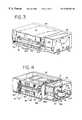
- FIG. 1is a perspective view of an apparatus for treating a biological fluid with light, embodying the present invention
- FIG. 2is a perspective view of the apparatus of FIG. 1 showing the modular components of the apparatus separated;
- FIG. 3is a perspective view of the apparatus of FIG. 1 with the front access door open;
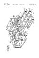
- FIG. 4is a perspective view of the apparatus of FIG. 1 with front, top and side panels removed;
- FIG. 5is a partially exploded view of the apparatus of FIG. 1;
- FIG. 6is a perspective view of a light drawer with socket panel open
- FIG. 6Ais an exploded view of the light drawer of FIG. 6 .
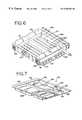
- FIG. 7is a perspective view of a fluid container carrying tray
- FIG. 8is a perspective view of fluid carrying drawer with tray removed
- FIG. 8Ais a partial side view of the drawer tilt knob and assembly of the fluid carrying drawer
- FIG. 8Bis a modified partial side view of the drawer tilt knob and assembly of the fluid carrying drawer
- FIG. 9is another perspective view, from the underside, of the fluid carrying drawer without fluid container carrying tray
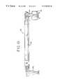
- FIG. 10is a front view of the fluid carrying drawer with fluid carrying tray removed showing side to side oscillation of the tray;
- FIG. 11is a perspective view of container marker assembly
- FIG. 11Ais another perspective view, from the underside, of the container marker assembly
- FIG. 12is an enlarged perspective view of an individual marking unit of the container marker assembly
- FIG. 13is a perspective view of stacked apparatus embodying the present invention.
- FIG. 14is a block diagram of the control system of the apparatus embodying the present invention.
- FIG. 14Ais a perspective view of a light sensing device which may be used with the apparatus of FIG. 1;
- FIG. 15is a plan view of a disposable fluid processing set embodying the present invention.
- FIG. 16is a plan view of another disposable fluid processing set embodying the present invention.
- FIG. 17is a plan view of a disposable fluid processing set embodying the present invention in position for attachment with containers of a collected biological fluid;
- FIG. 18is a perspective view of a part of the disposable fluid processing set embodying the present invention that includes at least one container disposed within a holder;
- FIG. 18Ais a perspective view of an alternative embodiment of the holder in a closed position with containers disposed therein;
- FIG. 18Bis a perspective view of the holder of FIG. 18A in an open position but without container(s);
- FIG. 18Cis a perspective view of another alternative embodiment of a holder in an open position
- FIG. 18Dis a perspective view of another alternative embodiment of a holder with frame portions separated
- FIG. 19is a flow chart showing the start-up phase of the control system for the present invention.
- FIG. 20Ais a flow chart showing the pretreatment phase of the control system for the present invention.
- FIG. 20Bis a continuation of the flow chart of FIG. 20A;
- FIG. 21is a flow chart showing the treatment phase of the control system for the present invention.
- FIG. 22is a flow chart showing the operator initiated instrument settings functions of the control system for the present invention.
- FIG. 23is a flow chart showing the diagnostic functions of the control system for the present invention.
- Light box 10An apparatus for treating a biological fluid is generally shown in FIGS. 1-14 and is referred to herein generally as light box 10 .
- Light box 10may be used for treating a variety of materials for a variety of purposes.
- Light box 10is particularly useful in the treatment of biological fluids.
- biological fluidrefers to any fluid that is found in or that may be introduced into the body including, but not limited to, blood and blood products.
- blood productrefers to whole blood or a component of whole blood such as red blood cells, white blood cells, platelets, plasma or a combination of one or more of such components that have been separated from whole blood.
- light box 10is in the treatment of a blood product that has been combined with a photochemical agent for activation when subjected to light.
- photochemical agentsare used, for example, in the inactivation of viruses, bacteria, white blood cells and other contaminants (collectively referred to herein as “pathogens”).
- pathogensviruses, bacteria, white blood cells and other contaminants
- the activated agentinactivates pathogens that may be present in a blood product.
- the biological fluid to be treatedis introduced into a fluid treatment chamber within light box 10 in flexible, plastic, sterilizable, translucent, biologically compatible containers.
- the containersmay be integrally connected to other containers and plastic tubing useful in the processing of the biological fluid both before and after the treatment provided by light box 10 . Examples of the disposable processing set and its components are shown in FIGS. 15-18. The light box, the disposable processing set and the methods of using them are described in more detail below.
- light box 10includes a housing 12 defined by top panel 14 , bottom panel 16 , front and rear panels 17 , and side panels 18 .
- Housing 12is supported by feet 13 attached to bottom panel 16 (FIG. 4 ).
- feet 13are rubber or other elastomeric mounts.
- Side panels 18may include handles 22 for grasping and transporting light box 10 .
- An openable or removable door 24 in side panel 18allows for access to the interior of light box 10 and, more specifically, the electronic components of light box 10 , which are described in more detail below.
- Door 24may be opened or removed by turning fasteners 25 .
- light box 10be fairly compact.
- light box 10may be approximately 100 cm wide, 20-40 cm deep and between approximately 30-40 cm high.
- a compact instrumentallows, for example, for placement of a greater number of instruments per treatment center and/or may allow two or more instruments to be stacked on top of each other (as shown in FIG. 13 ), resulting in greater throughput of biological fluid per horizontal area or space (i.e. bench space, shelf space).
- Light box 10may include a control module 26 and a fluid treatment module 28 .
- control module 26may include and/or house the command and control elements for the treatment of biological fluid.
- Fluid treatment module 28houses the elements and components where fluid processing takes place.
- Control module 26 and fluid treatment module 28may be contained in the same housing but in a preferred embodiment, as shown in FIG. 2, they are readily separable modules. Control module 26 and fluid treatment module 28 are electrically and physically connected when light box 10 is in use, but may be separated as shown in FIG. 2 . In one embodiment, control module 26 and fluid treatment module 28 are held together, in part, by draw pin 30 (FIG. 4) which holds together interfitting parts of the modules. Control module 26 and fluid treatment module 28 may be separated by removing draw pin 30 and turning of fasteners 31 shown in FIG. 4 . Fasteners 31 may be accessed by removing door 24 (shown in FIG. 1) in side panel 18 . Of course, other means of connecting and readily separating control and fluid treatment modules may be used, including, mating clips and slots on the facing panels of the control 26 and fluid treatment module 28 .
- Providing light box 10 in two readily separable modules 26 and 28allows for easier access to the control and fluid treatment modules 26 and 28 and, generally, provides for easier serviceability of light box 10 . For example, if off-site service is required for control module 26 only, that module can be removed without requiring removal and transport of the entire light box 10 .
- control module 26includes a control panel 32 located in the front of light box 10 .
- Control panel 32includes, a display screen 37 such as, but not limited to, an LCD display for providing graphical, textual and alphanumerical information to the operator regarding the treatment process.
- a key pad 39is included within control panel 32 of control module 26 to allow operator control over the process and/or f or data entry by the operator. Additional means of data entry are provided by bar code reader 41 which, when not in use, rests in slot 43 .
- a trough 45may be provided for the coiled cable of bar code reader 41 .
- Control panelmay also include the on/off switch 35 for light box 10 .
- Control module 26will typically include a programmable microprocessor for operation of light box 10 including central processing unit 27 and memory devices such as random access memory (RAM) and EPROMS for the system program storage and non-volatile memory for back-up data storage.
- Control module 26may further include an isolation transformer 29 for converting an AC input voltage to a DC control system voltage and for maintaining leakage current within acceptable limits for medical devices.
- Other components within control module 26may include power supply 167 , input/output board 33 and a power inlet module 34 , filtered pass through 34 b for use with an external light intensity sensing device and filtered output pass through 34 a.
- Control module 26may be adapted for connection to external components such as a printer 500 (FIG. 14) through parallel and/or serial ports 34 C, or to a central computer 502 (FIG. 14) that is connected to several light boxes and/or other medical devices.
- the central computercan receive data from the several instruments, allowing the operator at a treatment center to retrieve information regarding the several procedures.
- control module 26may also include other components such as additional printed circuit boards shown in FIG. 14
- fluid treatment module 28includes front door 36 which when opened, allows for introduction and removal of the biological fluid into a fluid treatment chamber, as described in more detail below.
- the front panel 17 of fluid treatment module 28may also be opened to allow for fuller access to the interior of fluid treatment module.
- panel 17may include fasteners 17 a which, when turned, allow front panel 17 to be opened or removed.
- FIGS. 4-5generally show the interior of fluid treatment module 28 with at least top panel 14 and front panel 17 removed.
- fluid treatment module 28includes an interior framework 38 that defines, in part, a fluid treatment chamber 40 and light chambers 42 and 44 for housing light sources (described in more detail below).
- the framework 38may typically be constructed of any sturdy material which will allow light box 10 to support one or more additional light boxes as generally shown in FIG. 13.
- a preferred materialis aluminum and, in particular, Aluminum 6061 hardened to T-6.
- light box 10may include a single light chamber, placed in close proximity to fluid treatment chamber or two or more light chambers disposed around a fluid treatment chamber in other than “top and bottom” positions.
- fluid treatment chamber 40is adapted to receive fluid carrying drawer 50 .
- Light chambers 42 and 44are adapted to receive light drawers 60 and 70 .
- Fluid treatment module 28may further include a container marker assembly 74 shown, for example, in FIG. 5 .
- Marker assembly 74may carry one or more markers 76 a - 76 d for marking containers, before and/or after treatment, as will be discussed in more detail below.
- fluid carrying drawer 50allows for introduction of biological fluid into fluid treatment chamber 40 .
- Fluid carrying drawer 50may be moveable, either manually or automatically, into and out of fluid treatment chamber 40 .
- drawer 40may include handle 80 .
- movement of fluid carrying drawer 50is facilitated by slides 82 on either or both sides of drawer 50 , which are disposed within rails 86 of framework 38 , as best seen in FIGS. 8, 9 and 13 .
- fluid carrying drawer 50may include rollers or other devices which allow for movement of drawer 50 into and out of fluid treatment chamber 40 .
- fluid carrying drawer 50preferably includes a pivot mount that permits the drawer to be tilted downwardly when fully withdrawn.
- the ability to tilt drawer 50 downwardlymay be particularly useful for loading containers of fluid in the upper light boxes where two or more light boxes are stacked on top of each other, as shown in FIG. 13 .
- fluid carrying drawer 50may be hingedly attached to framework 38 so that when fluid carrying drawer 50 is fully opened and is outside of housing 12 , front edge of drawer 50 may be tilted downwardly at, for example, a 45° angle.
- light box 10may include spring loaded tilt knob 83 which, when pulled, releases fluid carrying drawer 50 and allows it to be tilted in the manner described above.
- tilt knob 83is connected to rod 82 a which is attached to slide 82 (FIG. 9 ).
- the end of rod 82 ais coupled to pivot member 83 a which is connected to ring 83 b attached to drawer 50 .
- Rod 82 afurther includes a spring 82 c and spring stops 82 d .
- spring 82 cWhen the end of rod 82 a is coupled to pivot member 83 a , movement of ring 83 b is prevented (as shown in FIG. 8 A).
- knob 83is pulled, (as shown in FIG. 8B) rod 82 a is uncoupled from pivot member 83 a , allowing ring to rotate relative to pivot member 83 a and, thereby, allowing drawer 50 to be tilted downwardly, as shown in FIG. 13 .
- fluid carrying drawer 50is generally open and includes a central cavity 88 to allow for placement of a container carrying tray 90 shown in FIG. 7 .
- Container carrying tray 90may be integral with fluid carrying drawer 50 , although, a removable non-integrated tray 90 may be preferable for easier container loading and/or tray cleaning.
- fluid carrying drawer 50be continuously or periodically agitated to provide mixing of the biological fluid and ensure that substantially all of the biological fluid is sufficiently and uniformly exposed to light and/or any photochemical agent. Accordingly, fluid carrying drawer 50 may be attached to means for agitating the biological fluid.
- fluid carrying drawer 50may include an agitation assembly that, for example, provides side-to side oscillation of tray 90 .
- Agitation assemblymay include a pair of fixed lower rails 95 b that extend front to back within light chamber.
- Upper rails 95 aare attached to the lower rails by pivotally attached link arms 93 a and 93 b .
- the link armsallow side-to-side motion of the upper rails 95 a .
- an electrical motor 92is attached to lower rail 95 b .
- Motor 92rotates a cam 97 a .
- Cam 97 amay be an L-shaped crank or bracket attached to roller 97 .
- Roller 97is captured between parallel walls 97 b depending from upper rail 95 a .
- crank 97 acauses roller 97 to orbit around the motor 92 axis, roller slides fore and aft and up and down between walls 97 b , imparting side-to-side motion of upper rail 95 a.
- Light box 10may include one or more light sources, preferably disposed above and below fluid treatment chamber 50 .
- the light source(s)be readily accessible.
- “readily accessible”means that access to the light source can be quickly and easily had without the use of, for example, a screwdriver or other tools.
- the light sourceit may be desirable that the light source be either partially or completely removable from the housing 12 and/or fluid treatment module 28 .
- the light source(s)may be accessible through any one of the front, side, top or bottom panels.
- the light sourcesare housed in light drawers 60 and 70 . As shown in FIG.
- Light drawers 60 and 70may include slides 99 (FIG. 6) attached to the bottom surface of drawers 60 and 70 . Slides 99 rest and move on brackets 96 and slide mounting blocks 98 of framework 38 as shown in FIG. 5 . Light drawers 60 and 70 may also include handles 84 for grasping during insertion and removal.
- light drawer 60 and/or 70may be divided into two or more chambers 101 and 103 separated by dividing wall 102 .
- Dividing wall 102minimizes light from one light chamber of radiating into the other light chamber. This ensures that the light emitted from each lamp or lamp array and contacting the biological fluid is substantially constant.
- each of the lamp arrays within light chambers 101 and 103may be independently monitored and controlled from control module 26 . Thus, when one array of lamps is turned off, the other array of lamps may remain on. As described in more detail below, this may be particularly useful where two or more containers of biological fluid requiring different levels of treatment are being treated.
- Each of light chambers 101 and 103 of light drawer 60 or 70is generally defined by four side walls 105 a-d and a bottom wall 107 .
- Walls 105 a-d and 107may be made of or coated with a reflective material to maximize the amount of light delivered to the biological fluid.
- the light sourceprovides light in the ultraviolet A (UVA) range
- walls 105 a-d and 107may be made of a highly reflective aluminum to provide substantial reflection of UVA light.
- a materialis sold under the name 1500 G-2 and is available from ALANOD of Ennepetal, Germany.
- the light sources suitable for use in the present inventionmay include any light source that is capable of providing light of a particular wavelength and intensity for treating a particular biological fluid.
- light sources capable of providing white light, red light, infrared, ultraviolet A and/or B lightmay be used.
- Light drawers 60 and 70may include a single lamp or an array of multiple lamps 100 .
- light sourcemay include standard fluorescent lamps or bulbs capable of providing light of a wavelength in the UVA (ultraviolet A) range. Such lamps may be obtained from Sagyo Denkai of Japan under the product code BL352.
- Light drawers 60 and 70further include fans 109 for cooling lamps 100 and, more specifically, ends of lamps 100 at or near the lamp filaments.
- Socket panelmay also serve as a printed circuit board. Socket panel 106 may be hinged and openable to allow for easy access to lamps 100 , easy insertion and removal of lamps 100 , and in general, easier serviceability of light drawers 60 and 70 .
- a portion of fluid treatment chamber 40 and, for that matter, fluid carrying drawer 50are separated from light drawers 60 and 70 by glass plates 110 .
- upper glass plate 110rests on framework 38 and is, generally, held in place by clamps 112 and 114 .
- a lower glass plate 110 separating a portion of fluid carrying drawer 50 from lower light drawer 70may also be included.
- Glass plates 110are substantially translucent to light of the wavelengths used for the treatment of biological fluid. Preferably, glass plates 110 may also filter unwanted light. Alternatively, a separate filter may be provided for placement between the light source and the fluid treatment chamber 40 .
- glass plate 110may be substantially translucent to ultraviolet light within the range to 320-400 nm, but not translucent to light of a wavelength of less than about 320 nm.
- Such glass platesare commercially available from Schott Glass of Yonkers, N.Y. under the product designation B-270.
- fluid treatment module 28further includes marker assembly 74 .
- Marker assembly 74may include one or more markers 76 a - 76 d for marking containers within fluid treatment chamber.
- One or more markers 76may be provided to mark containers at different stages of the treatment.
- Markers 76 a-dmay be punches for punching holes into a portion of the container such as the container flap as described in U.S. Pat. No. 5,557,098, which is incorporated by reference.
- markersmay be stampers for stamping designated portions of a container with ink.
- Such markersare commercially available from Trodat of Wels, Austria under the product name Printy 4911.
- marker assembly 74may include a plurality of markers 76 a-d for marking a plurality of containers during different stages of the light treatment. Markers 76 a-d may be attached to a bracket 78 which includes a slide 114 . Slide 114 is suspended from and movable within track 116 which is attached to the interior framework 38 of light box 10 . Thus the entire assembly 74 can be withdrawn from fluid treatment module 28 for reinking, replacement of markers 76 or for general servicing as shown in FIG. 5 .
- each individual marker unitincludes a marker drive motor 120 that moves markers 76 up and down through gear 122 , gear 124 , lead screw 128 , lead nut 126 , bracket 130 and spring 132 . Movement of gears 122 and 124 actuates movement of lead screw 128 and causes downward and/or upward movement of lead nut 126 , bracket 130 and consequently marker 76 .
- Fluid treatment module 28includes blower 134 which provides air flow into fluid treatment chamber 40 and fluid containers and thus, provides for temperature control of fluid treatment chamber 40 (FIG. 5 ).
- Blower 134receives ambient air through an opening in bottom wall 16 located below blower 134 .
- air from blower 134may also pass through opening 136 of fluid treatment module 28 and a perforation or opening 136 a in control module 26 , as seen, for example in FIGS. 2 and 4.
- fluid carrying drawer 50may include a tray 90 for holding one or more containers of biological fluid.
- Tray 90shown in FIG. 7, may be placed within the cavity 88 of the fluid carrying drawer 50 (FIG. 8 ).
- tray 90may be made of a molded plastic material. Where the biological fluid is treated from two sides, the molded plastic material should be sufficiently translucent to the light provided by the lamps 100 .
- Suitable materials for tray 90include acrylic polymers such as polymethyl methacrylate (PMMA) or members of the polyolefin family such as methylpentene copolymer. Such materials are available from many sources including CYRO Industries of Rockaway, N.J. under the product name ACRYLITE® OP4 or from Mitsui Plastics of White Plains, N.Y. under the name TPX.
- tray 90may be divided into a first portion 180 and a second portion 182 separated by dividing wall 184 . As shown in FIG. 7, tray 90 may include retaining tabs 186 for placing a slit or other aperture of a biological fluid container 206 over tab 186 to limit movement of the container within tray 90 and ensure that the container is substantially within the field of light provided by the light source.
- the volume of tray 90should be sufficient to hold at least the entire volume of biological fluid contained within the containers so as to minimize the risk that, in the event of container leakage, liquid will overflow and contact the electrical and mechanical components of light box 10 , even during agitation.
- tray 90may be compartmentalized to provide separate compartments for the container undergoing treatment on the one hand, and the remainder or a portion of the remainder of the disposable processing set, on the other hand.
- first portion 180 and second portion 182each include a first compartment 188 and second compartment 190 separated by discontinuous wall 192 .
- First compartment 188may hold a container of biological fluid 206 and the second compartment may hold the remaining components of the fluid processing set.
- a slot in the wall 192accommodates the tubing that connects container 206 with the remainder of the disposable processing set.
- Tray 90 or second compartment 190 of traymay further include container retaining tabs or pegs 193 to assist in holding the containers in the second compartment in place and limiting movement of such containers within tray 90 .
- container 206 within a first compartment 188is positioned substantially within the field of light provided by the light source.
- the remainder of the disposable processing set and/or containers within a second compartment 190are aligned substantially with marker assembly 74 as shown in FIGS. 4 and 5.
- the status of the treatmentmay be indicated on the other containers of the processing set within the second compartment 190 by markers 76 a-d.
- Light box 10may include sensors for detecting different conditions during the pretreatment and treatment process.
- the sensorsrelay signals to the microprocessor of the light box 10 which is housed within control module 26 .
- sensorse.g., 404 , 430
- the computeralerts the operator, either by an audible alarm or a message on the display screen 37 .
- the operatormay, in response to the alarm or message, take action through keypad 39 .
- the control systemmay be preprogrammed to automatically take action, such as terminate treatment, if necessary.
- light box 10may include internal light intensity sensors 404 for measuring the intensity of light provided by the lamps 100 to fluid treatment chamber 50 .
- sensor 404sends a signal through input/output board 170 (FIG. 14) to microprocessor 160 as described above.
- light intensity sensors 404may be located within the light chambers 101 and 103 of light drawers 60 and 70 (FIG. 6 ).
- light drawer 60 and/or 70include a light intensity sensor subassembly 402 on the underside of drawer 60 and/or 70 .
- subassembly 402includes two or more sensors 404 attached thereon and placed within sensor windows 406 located in the bottom wall 107 of drawers 60 and/or 70 .
- Sensor windows 406allow light from lamps 100 to pass through and contact sensors 404 .
- Sensors 404may include or be used with one or more filters to filter out unwanted light.
- the filters used in association with sensors 404have a maximum sensitivity in the wavelength range that substantially matches the wavelength range within which the particular photochemical agent is most effectively activated (i.e., the “action curve”). This allows sensor 404 to detect the effectiveness of photochemical activation.
- sensorsare available from Texas Advanced Optoelectronics Solutions under the product code TSL230B. Filters are available from a variety of sources such as Schott Technical Glass of Duryea, Pa.
- a fluid carrying drawer sensor 144may be included for monitoring the position of fluid carrying drawer within fluid treatment chamber 40 .
- Fluid carrying drawer positioning sensor 144ensures that the drawer 50 is in a fully closed position and therefore, that containers of biological fluid are substantially within the field of light provided by lamps 100 . If the drawer is not in a fully closed position, sensor 144 sends a signal to the microprocessor, alerting the operator and preventing treatment from proceeding.
- Light box 10may further include temperature sensors 145 for either directly or indirectly monitoring and measuring the temperature within fluid treatment chamber 40 .
- Temperature sensormay be disposed within the fluid treatment chamber 40 or, as shown in FIGS. 4 and 5, may be disposed on the exterior of light box 10 to measure the ambient temperature of the outside environment.
- ambient temperature sensor 145may be located anywhere on the surface of light box 10 .
- ambient temperature sensor 145is placed at or near control module 26 .
- Ambient temperature sensor 145provides an indication of the air temperature being delivered to fluid treatment chamber by blower 134 .
- the ambient temperature sensorsends a signal to the microprocessor as generally described above, which alerts the operator that the temperature is approaching or has exceeded its limit. Accordingly, the operator and/or instrument may take further action.
- Sensor 430may be attached to marker subassembly 74 , as shown in FIG. 11A, and measures movement of the agitation assembly described above.
- sensor 430may include an infrared source such as, but not limited to a light emitting diode (LED) or laser that contacts a selected reflective portion of the agitation assembly. If sensor 430 does not detect reflection or does not detect reflection at the predetermined frequency, it signals the microprocessor accordingly.
- LEDlight emitting diode
- Light box 10may also include a sensor 440 to detect whether the front door of the light box is closed during treatment.
- Door sensormay be a magnetic switch which detects contact between door 36 and magnetic plate 441 shown in FIG. 3 .
- plunger switch 36 a(FIG. 4) is pressed when door 36 is closed. If door 36 is open, plunger switch 36 a serves as an electrical cut off. If, the door is open, the system will not permit the treatment to proceed.
- Light box 10may also include sensors 450 for determining whether containers are in position for marking by markers 76 .
- sensors 450may be attached to markers 76 and may include optical receivers aligned with light emitting diodes (LED) (not shown) typically located below fluid carrying tray 90 .
- LEDlight emitting diodes
- the labels of containers placed within the second compartment 190 of tray 90prevent optical receiver 450 from receiving the LED signal, indicating the presence of a container. Conversely, if sensor 450 receives the signal, this indicates that no container is present and the marker will not be activated.
- each marker 76 a-dmay include a microswitch (shown as 470 in FIG. 14) to detect whether movement of the marker has occurred and to prevent mechanical failure or damage to the parts that make up the marker.
- Radiometer 460may be provided to verify light intensity provided by light box 10 and for calibration of light box 10 .
- Radiometer 460may be adapted for placement within fluid treatment chamber 40 for measuring the energy dose delivered to the biological fluid. More specifically, radiometer 460 may be adapted for placement within the fluid container carrying tray 90 . In one embodiment, radiometer 460 may be adapted for placement within a compartment of tray 90 such as first compartment 188 of tray 90 .
- radiometer 460may include a support 465 having a top surface 467 and a bottom surface 468 .
- Support 465is typically a printed circuit board.
- One or more sensors 469are electrically and physically connected to support 465 .
- radiometer 460may include a plurality of sensors spaced across the top and/or bottom surface(s) to receive light from different points on one or more lamps. Also, sensors 469 may be placed on one side of support 465 , but preferably are placed on both the top surface 467 and the bottom surface 468 . Top and bottom placement of sensors 469 is particularly preferred where radiometer 460 is used to measure light provided by two facing light sources, such as in one of the embodiments of light box 10 .
- Radiometer 460An electrical cord (not shown) is attached to radiometer 460 for electrical connection to light box 10 and, for example, port 461 (FIG. 5 ). This allows radiometer 460 to transmit data to the computer-based control system of light box 10 , which system provides information to the operator and/or automatically takes action based on the transmitted data. Radiometer 460 may also include a slit 472 for placement over tab 186 in tray 90 of light box 10 .
- Sensors 469may typically be photodiodes capable of detecting light of selected wavelengths. Sensors 469 may also include or be used with filters to filter out unwanted light as substantially described above.
- radiometer 460When used in connection with light box 10 , it is preferred that the dimensions of radiometer 460 be substantially equivalent to the dimensions of the fluid-filled containers used with light box 10 . Accordingly, it is preferred that the light sensing area of radiometer 460 have a height, a width and a thickness substantially equal to such filled containers. A radiometer with dimensions substantially equal to the fluid-filled container provides a reliable approximation of the energy being delivered to the fluid and of the effectiveness of the treatment.
- radiometer 460may be used for light intensity verification by, for example, the operator and for calibration of light box 10 generally and more specifically, of internal sensors 404 .
- the operatormay place radiometer 460 in first compartment 188 of tray 90 .
- Cordmay be pressed into strain relief tabs 474 within light box 10 (FIG. 8 ).
- the fluid carrying drawer 50is inserted into fluid treatment chamber 40 and door 36 is closed.
- Lamps 100are turned on and the light delivered is measured by sensors 469 .
- the light measured by sensors 469is processed by the system's microprocessor to provide a reading of the energy being provided to the fluid treatment chamber 40 .
- the operatorcan monitor the output of lamps 100 and determine any diminishment in the lamp output by comparing the reading to a pre-set acceptable energy dose range.
- the readings provided by sensors 469are also compared to the readings provided by sensors 404 to detect any diminished sensing capability of sensors 404 .
- Radiometer 460may also be used to calibrate light box 10 . Radiometer 460 itself may be calibrated against a standard (e.g. a standard from the National Institute for Standards and Technology or NIST).
- radiometer 460may have utility in other applications and is not limited to use in the apparatus or methods of the present invention. Indeed, radiometer 460 may be used whenever light is to be measured over an extended surface area.
- the components of the fluid treatment module 28 including the agitator assembly, the light sources, the blower, the marker subassemblyare powered by power supplies as shown in FIG. 14 .
- the letter “n”represents the number of electrical or mechanical components such as sensors, lamps, ballasts etc.).
- power supplies (ballasts) 166power lamps 100 and are controlled and supplied by relay board and isolation transformer 29 .
- Shaker motor 92is powered through relay board and isolation transformer 29 .
- Additional power supply 168supplies power for the blower 134 , light drawer fans 109 , and drive motors 120 for markers 76 a-d and door lock 480 .
- the power supply for powering these componentsmay be approximately 24 volts DC.
- Power supply 167may supply +5, +12, ⁇ 12 volts DC to, for example, computer board 160 .
- light box 10includes a programmable computer software-based control system to control the operation of light box.
- the control systemis generally and diagrammatically depicted in FIGS. 19-23 and is described in greater detail in connection with the description of the method of processing and treating a biological fluid which follows the description of the disposable processing set provided below.
- Disposable processing sets useful with light box 10are shown in FIGS. 15-18.
- the disposable processing setwill include two or more plastic containers integrally connected by plastic tubing. At least one of the containers should be suitable for holding the biological fluid during light treatment. The other container should be suitable for storage of the biological fluid after treatment.
- the disposable processing setmay be joined with containers of biological fluid, and the fluid may be transferred to containers of the disposable processing set.
- Processing set 200includes a container 202 , a container 206 , a container 210 and a container 214 .
- the containersmay be integrally interconnected with tubing segments as generally shown and described in detail below.
- the sizes and internal volumes of containers 202 , 206 , 210 and 214may vary depending on the biological fluid being processed.
- container 202may be capable of holding approximately 15-30 ml of fluid
- containers 206 and 210approximately 1000 ml
- container 214between approximately 1000-1500 ml.
- other desirable sizes and volumesmay be used and are within the scope of the present invention.
- container 202may include, for example, a photochemical agent which is mixed with the biological fluid.
- photochemical agentsinclude psoralen compounds described in U.S. Pat. No. 5,709,991 and compounds from the family of phenothiazine dyes such as, but not limited to, methylene blue.
- Container 202may be made of any material suitable for holding such photochemical agents.
- One such materialmay be a blend of ethylene polypropylene, polyamide and a block copolymer of ethylene and butylene with terminal blocks of polystyrene. Containers made of such material are available from Baxter Healthcare Corporation under the name PL2411.
- Container 202includes a tubing segment 203 extending therefrom and having a sealed end 204 .
- a second tubing 205 extending from container 202is integrally connected to container 206 .
- the photochemical agentmay be contained or predisposed within container 206 , thereby eliminating the need for a separate container 202 for holding the photochemical agent.
- the photochemical agentmay be combined with the biological fluid prior to joinder to the disposable processing set.
- the photochemical agentmay be included in a container 201 used to hold the biological fluid collected from a donor (FIG. 17 ).
- Container 206is preferably a container suitable for holding the biological fluid during light treatment. Accordingly, it is desirable that container 206 be made of a clear, durable, thermoplastic material that is translucent to light of the selected wavelength and sterilizable by known forms of sterilization including steam sterilization, gamma and electron beam radiation.
- containeris made of a material that is substantially translucent to UVA light and remains stable after sterilization.
- materialsmay include polyvinyl chloride, but more preferably, may be blends of thermoplastic polymers and copolymers, including general purpose polymers, elastomers and the like.
- One such materialincludes the block copolymer described above which includes a central block of ethylene and butylene and terminal blocks of polystyrene.
- Block copolymers of the type described aboveare available from the Shell Chemical Company under the name KRATON.
- the block copolymermay be blended with other polymers such as ultra low density polyethylene (ULDPE) and ethylene vinyl acetate (EVA).
- ULDPEultra low density polyethylene
- EVAethylene vinyl acetate
- Containers made of the blended materialare available from Baxter Healthcare Corporation of Deerfield, Ill. under the name PL-2410.
- Other thermoplastic materialsmay also be suitable for container 206 , including materials including KRATON, EVA, and polypropylene.
- a container made from such materialis also available from Baxter Healthcare Corporation under the name PL-732.
- Still other suitable materials for container 206include fluoropolymers such as polytetrafluoroethylene (PTFE), PFA or copolymers including such fluoropoly
- Container 206further includes a slit 207 which, as described above, may be placed over retaining tab 186 in tray 90 .
- Container 206includes a tubing segment 208 which may be integrally connected to a container 210 .
- container 210may, for example, include an adsorbent material 211 for removing excess photochemical agent or the byproducts of the photoactivation process.
- the adsorbent materialmay be contained in a semi-permeable pouch, preferably affixed to the container walls or portions thereof within the interior chamber of container 210 .
- the interior chamber of container 210has a volume sufficient to hold the biological fluid from container 206 .
- Such a container and the adsorbent materialare disclosed in more detail in copending patent application entitled “Plastic Containers Having Inner Pouches and Methods for Making Such Containers” which is being filed simultaneously herewith in the names of Mahmood Mohiuddin, George D. Cimino and Derek J. Hei, and is incorporated by reference in its entirety. Materials such as those used in the PL-2410 and PL-732 containers described above are suitable for use in container 210 .
- Container 210may also include a time-sensitive tape 209 . Tape 209 changes color with time, thus informing the operator if the biological fluid has contacted the adsorbent material for a sufficient period of time.
- Container 210may be integrally connected by tubing segment 211 to another container 214 which may be suitable for storage of the biological fluid. As shown in FIG. 15, the portion of tubing segment 211 that communicates with the interior of container 210 may include a filter 211 a to capture loose particles of adsorbent, if any.
- Container 214may include and/or be capable of receiving a label 216 which may carry bar codes 222 or other indicia which provide information about the biological fluid.
- bar codes 222may identify the donor, the product, the lot number of the biological fluid, expiration date and the like.
- Container 214may include additional bar codes or indicia 224 which are used to provide information regarding the status or progress of the fluid treatment (described in more detail below).
- Container 214may also include a slit 226 and/or apertures 228 , 230 for placement over corresponding pegs ( 193 ) on tray 90 . Materials such as those described above are suitable for use in container 214 .
- Container 214may also include sampling pouches 214 a and access ports 214 b to allow for fluid access during later transfusion, as will be recoginzed by those of ordinary skill.
- disposable processing setmay include a single container for housing the adsorbent material of container 210 and for storing the biological fluid, thereby combining the functions of container 210 and 214 described above.
- the disposable processing set 200 described hereinmay further include frangible members 230 ( a-c ) disposed within tubing segments as shown in FIG. 15 .
- Frangible members 230are broken at the appropriate time to establish fluid communication between the containers of the processing set 200 .
- frangible connectorsare described in detail in U.S. Pat. No. 4,294,297 which is incorporated by reference herein.
- Tubing segments of disposable processing set 200may further include indicators 234 a and 234 b on the tubing to indicate proper positioning of the disposable processing set within the tray 90 (as will be described more detail below) and/or to serve as indicators of where tubing is to be severed and sealed.
- indicators 234may be plastic rings disposed around tubing segments. Of course, other tubing indicating means may be used.
- disposable processing set 240also includes a container 242 which carries a photochemical agent, a container 244 which holds the biological fluid during light treatment, a container 246 which includes an adsorbent material for removing excess photochemical agent and/or the byproducts of the photoactivation process, and a container 248 suitable for storage of the biological fluid.
- Container 248is adapted to receive label 249 with bar codes or other indicia and may include additional indicia 251 including, for example, additional bar codes as substantially described above.
- container 246is a flow through device which includes adsorbent material 212 but does not include a chamber for holding the biological fluid for any significant period of time.
- Disposable processing set 240may further include an air reservoir 256 and air sink 258 .
- Air reservoir 256provides air to help expel biological fluid from container 244 and air sink 258 receives excess air expelled from storage container 248 after processing.
- Air reservoir 256 and air sink 258may be made of any suitable biocompatible material, including the materials described above.
- the containers of disposable processing set 240may also be made from the materials generally described above.
- container 256is substantially impermeable to air.
- the containers of disposable processing set 240 shown in FIG. 16may be integrally interconnected by tubing segments 243 , 245 and 247 .
- Tubing segmentsmay further include frangible members 249 ( a-c ) for opening fluid communication between the containers.
- Disposable processing set 200(or 240 ) is typically provided to the user in a sealed package in a manner that is easy for the user to unpack and use. For example, upon opening the package, it is preferred that the container to be used first in the fluid processing be located near the top of the package. For example, in the processing set 200 shown in FIG. 15, container 202 would be located near the top of the package, followed by container 206 , followed by the remainder of the disposable processing set that includes containers 210 and 214 . In addition, if disposable processing set includes container 202 , (or 242 in the embodiment of FIG. 16) at least such container should include a separate and additional light impermeable overwrap to protect the contents (i.e. the photochemical agent) from exposure to light which could result in premature activation of the photochemical agent. In one embodiment, the light impermeable overwrap may be permanently sealed to the outer walls of container 202 .
- containers 210 and 214may be contained within or held together by a holder.
- Holdermay be any device such as a clamp that holds together containers 210 and 214 .
- the holdermay be integral with the disposable processing set or may be provided separately.
- holder 260may be a receptacle or other shell-like holding device.
- holder 260may include a bottom wall 262 which separates the containers 210 and 214 from container 206 .
- holder 260may have sidewalls 262 and 264 , a back wall 268 and includes a substantially open front portion as shown in FIGS. 17-18.
- bottom wall 262may include a slot 263 to accommodate tubing that connects containers of disposable processing set 200 .
- Holder 260may also include additional side openings 265 (shown, for example, in FIG. 17) for holding tubing segments of container 202 prior to unpackaging of the disposable processing set.
- Holder 260may be made of any suitable material such as but not limited to plastic or cardboard.
- holder 260is made of a moldable plastic material that may be sterilizable and impact resistant.
- FIGS. 18A-18DAlternative embodiments of holder 260 are shown in FIGS. 18A-18D.
- holdermay include two frame or partial frame portions 600 and 602 .
- Frame portions 600 and 602may be joined and include hinge 604 as shown in FIGS. 18B and 18C.
- frame members 600 and 602may be completely separable as shown in FIG. 18 D.
- Frame portions 600 and 602include means for securing together the frame portions such as mating slots 605 and pins or lugs 606 as shown.
- Holder 260 shown in FIGS. 18A-18Dincludes a central opening 608 to allow the label of a container placed within holder 260 to be exposed to the outside environment to allow scanning by, for example, a bar code reader and/or marking by markers 76 as described below.
- container 210is placed in the front portion of holder 260 , such that a label to be applied to the container 210 and other indicia on the container itself are exposed to the outside environment through the open portion of holder 260 as shown in FIG. 17 .
- labelis shown as applied to container 214 .
- container 214may not include label at the time of use and a label may be transferred to container 214 from a container of biological fluid.
- container 214may include a label and an additional label may be transferred from a container of biological fluid.
- container 214may be folded in half (or tri-folded) with container 210 (also folded) placed behind container 214 .
- folded container 214may be lightly spot welded at its ends to keep the container folded and improve handleability of the container.
- the weldshould be sufficiently strong to keep container 214 in a folded position, but not so strong that undue force applied by the user would be required to disconnect the welded ends. Spot welded ends of container 210 should release when tugged gently by the user.
- a container of collected blood or biological fluidis provided.
- representative methods of collecting blood productsinclude the automated and manual centrifugal processing, separation and collection of blood products, membrane separation of blood products and the like.
- AMICUS® Separatorsold by Baxter Healthcare Corporation.
- containers of the collected blood productwill typically bear a label that includes information identifying the donor, the blood product and lot numbers. Most typically, such information is presented in the form of one or more bar codes on the label which can be scanned and read by bar code reader, such as bar code reader 41 of light box 10 .
- bar code reader 41 of light box 10Such labels may be removable and transferable to container 214 of the disposable processing set 200 .
- the collection containerwill include a tubing segment extending therefrom. Accordingly, tubing from the collection container 201 and tubing segment 203 from the disposable processing set 200 are brought together and joined in a sterile manner, as shown generally in FIG. 17.
- a device that is useful for the the sterile joinder of tubing portionsis available from Terumo Corporation of Japan and sold under the name Terumo SCD. This device heat seals two opposing tubing portions in a sterile manner. The heat from the heat sealing kills any bacteria from the outside environment that may enter or reside in the tubing segments, thereby preserving the sterility of the entire processing set.
- any method and apparatus for joining two tubing segments while maintaining sterilitymay be used.
- frangible member 230 ais broken to provide an open flow path from the collection container 201 to the container 206 (FIG. 15 ). Photochemical agent from container 202 is also allowed to flow into container 206 . After fluid transfer to container 206 , tubing segment may be severed and sealed and the portion of the disposable processing set that included container 202 and the collection container(s) 201 are discarded. Indicator 234 a provides a reference point as to where the tubing is to be severed. It is preferable that the indicator be placed as close as possible to the container 206 so that most of the biological fluid is retained within container 206 where it is most likely to be mixed and treated.
- operatormay scan the label and other container indicia with bar code reader 41 .
- Bar codes 222 on the main container label 216 or the container itselfprovide the instrument with information regarding the biological fluid to be treated. Based on the data, the light treating instrument or operator prescribes the light dosage and then calculates the duration of the treatment.
- Container 206 of disposable processing set 200is typically placed in first compartment of tray 90 .
- Slit 207 in container 206is placed over retaining tab 186 in first compartment 188 and holder 260 with containers placed therein are placed within the second compartment 190 of tray 90 .
- Slits and/or apertures in container 216are likewise placed over retaining tabs or pegs 193 in second compartment 190 .
- Tubing connecting container 206 with container 210 (and/or 214 )may be pressed into the slot in wall 192 . It is preferable that the tubing be positioned parrallel to the direction of the side-to-side oscillation provided by the agitator assembly described above. This further ensures that any fluid within tubing segment 208 is also mixed.
- Indicator 234 bnot only serves as a reference point for severance of the tubing but also serves as a reference point for container placement by ensuring that substantially the entire container and biological fluid therein is within the field of light.
- the indicatorhas a diameter greater than the width of the slot.
- plunger switch 36 a(FIG. 4) is pressed when door 36 is closed. If door 36 is open, plunger switch 36 a serves as an electrical cut off. If, the door is open, the system will not permit the treatment to proceed.
- Light box 10includes a programmable computer software-based control system to control the operation of light box 10 .
- the control systemis generally and diagrammatically depicted in FIGS. 19-23. As shown in FIGS. 19-23, the system tests, monitors and controls various aspects of the light box 10 and treatment operation such as the start up, container loading, container treatment and container unloading stages of the light box operation.
- the control systemallows the operator to take action or advises the operator of the treatment status through either an alphanumeric or a graphical user interface displayed on screen 37 .
- the various functionsmay be initiated by the operator through control panel or automatically by the control system itself.
- the control systemwill initiate a series of steps including loading the software 301 , initializing the software 302 , and displaying the graphical user interface screen and menu 304 .
- the operatormay then select from the series of available functions including the treatment function 306 or general user function 308 .
- the operatormay choose to exit the system 312 .
- Diagnostic checks 310may also be selected and performed, typically by a service technician.
- the control systemthrough the programmed software will automatically determine if treatment is appropriate and more particularly, if the light box 10 is prepared for treatment as shown in FIG. 20 A.
- treatmentwill not be enabled and would not proceed until the condition is remedied.
- the systemwill prompt the operator to input his or her unique identifier 314 and then request the input of container (i.e. biological fluid) information 316 .
- Container informationmay be input manually or by scanning bar codes 222 on, for example, container 214 shown in FIG. 15 . If treatment is appropriate, the system proceeds to the next function or phase as generally shown in FIG. 20 B.
- the control systemdisplays additional options for the operator to select. For example, the operator may proceed to treatment of the container, request treatment of a second container or cancel the operation entirely as shown in step 320 . If “Bag 2 ” option is selected, the operator is again requested to input container information 322 and the system will repeat the steps generally described above. If treatment on a single container is to be performed, the operator selects the treat function 324 which is generally shown in FIG. 20 B and described in more detail below.
- the instrumentmay display, for verification by the operator, information regarding the fluid to be treated and the treatment process generally. For example, in one embodiment, the instrument may display, the predetermined target dose of energy to be applied to containers, the selected treatment time and a running value of the dosage percent being applied to the biological fluid during the treatment as shown in 330 . Treatment will continue unless terminated by the operator or automatically terminated by the instrument in response to an alarm condition.
- containermay be marked by markers 76 at the beginning of treatment and after treatment is completed.
- the marks made by marker 76obliterate or otherwise masks the bar code, making it unreadable.
- a container with two masked bar codes 224indicates that treatment has been successfully completed.
- thisserves as an indication that treatment was not successfully completed and the container may have to be discarded.
- Masking of bar codes 224 by markers 76also ensures that a treated container will not be treated again.
- the systemperforms an energy calculation 332 which is computed by multiplying the light intensity sensor readings by preselected calibration factors, averaging the readings across the sensors in the same chamber and plane and adding the reading received for planes in the same chamber.
- the control systemfurther verifies the treatment status 334 . If treatment is completed, the system will automatically turn off lamps 100 as shown in 336 .
- the systemmay automatically update information on the lamp life as shown in 337 and update container records 338 .
- Control systemmay continue to power shaker motor 92 until terminated.
- the resultsmay be transmitted to a central computer 502 (FIG. 14 ).
- the systemwill prompt the operator to unload containers 342 and may prompt the user to perform another treatment, if desired, as shown in 325 in FIG. 20 B. The process may be repeated as generally described above.
- Treatment time and energy dosagewill vary depending on the biological fluid to be treated.
- the treatment timemay be at least one minute but may also be less than one minute.
- the treatmentmay typically be anywhere between 1-30 minutes.
- treatmentis typically between 1-10 minutes, but more typically approximately 3-4 minutes.
- pathogen inactivation of blood plasmatreatment may also preferably be approximately 3-4 minutes.
- Energy per unit area, or energy fluxis the product of power per unit area or, in the case of radiant flux, at the target, and the time of exposure. Accordingly, the amount of energy per unit area delivered to the target (for example, in one embodiment, the biological fluid) will vary with the duration of exposure and the irradiance—the radiant power per unit area incident on the target.
- the total radiant energy flux deliveredmay be between approximately 1-100 J/cm 2 measured across a wavelength range of between approximately 400-700 nm.
- the total radiant energy flux delivered to the biological fluidmay preferably be between 1-20 Joules/cm 2 measured across a wavelength range of between approximately 320-400 nm.
- the total radiant energy flux delivered to blood platelets or blood plasmamay be between approximately 1-5 J/cm 2 and more typically approximately 3-4 J/cm 2 measured across a wavelength range of between approximately 320-400 nm.
- the energyshould not be outside the predetermined range in that excess heat generated within fluid treatment chamber 40 is to be avoided.
- temperature within chamber 40should typically not exceed 37° C. If an external temperature sensor of the type described above is used, the ambient temperature should be between 18°-30° C.
- tray 90is preferably agitated at a preset frequency.
- the frequencyshould not be so great so as to harm the biological fluid or components thereof.
- the tray 90may be agitated between approximately 50-100 cycles/min and for blood platelets, more preferably, between approximately 55-80 cycles/per minute.
- a cycleis defined as one complete back and forth oscillation of drawer 80 .
- fluid from container 206may be transferred to container 210 by breaking frangible number 230 b and opening the flow path between the containers 206 and 210 (FIG. 15 ).
- container 210may also include time-sensitive tabs 209 which change color over time. This way, the operator will know if the container has been in contact with the adsorbent material for the appropriate period of time.
- the adsorbent materialis selected to remove any residual photochemical agent or any by products of the photochemical process that may have been included in the biological fluid.
- the adsorbent materialmay include polystyrene beads or activated charcoal or other adsorbent material. Such materials are described in greater detail in International Publication No. WO 96/40857, incorporated by reference herein.
- the biological fluidmay simply pass-through container 246 without residing for any significant time, within the container.
- the details of the removal process and materials usedare described in the above-identified International Publication No. WO96/40857.
- the residence time, if any, of the biological fluid in container 210will be anywhere between approximately 30 seconds and 7 days.
- the biological fluidmay be transferred to container 214 (or 248 in FIG. 16) by breaking frangible member 230 C where it may be stored prior to transfusion to a recipient.
- Label 216 (or 249 ) applied to storage container 214 (or 248 )now carries identifying information regarding the donor and the fluid.
- Masked bar codes 224 (or 251 )indicate successful treatment of the biological fluid and that no additional treatment is required.
- the containermay be severed and sealed from the remaining portion of the disposable processing set as generally described above.
- control systemmay prompt the operator to perform other functions such as the maintenance function 336 which may include printing a maintenance log 338 , resetting lamp hours 340 resetting bag marker count 342 .
- the operatormay also select a system settings function 343 which allows the operator to set dates, times, languages 344 , 346 , 348 .
- the control systemmay allow the operator to perform certain container management functions such as transmitting or printing container records or overwriting container records 350 , 352 , 354 as generally depicted in FIG. 22 .
- the diagnostics function shown in general in FIG. 23may be selected. Selecting the diagnostics function allows the instrument to perform system tests 356 , device tests 358 or provides the operator with a settings menu 360 to select (or change) system identification settings, temperature parameters, shaker parameters, lamp parameters, radiometer parameters, lamp factors and light as generally depicted in FIG. 23 .
Landscapes
- Health & Medical Sciences (AREA)
- Life Sciences & Earth Sciences (AREA)
- Animal Behavior & Ethology (AREA)
- General Health & Medical Sciences (AREA)
- Public Health (AREA)
- Veterinary Medicine (AREA)
- Epidemiology (AREA)
- Chemical & Material Sciences (AREA)
- Engineering & Computer Science (AREA)
- Biomedical Technology (AREA)
- Medicinal Chemistry (AREA)
- Molecular Biology (AREA)
- Chemical Kinetics & Catalysis (AREA)
- Vascular Medicine (AREA)
- Heart & Thoracic Surgery (AREA)
- Cardiology (AREA)
- Anesthesiology (AREA)
- Hematology (AREA)
- Apparatus For Disinfection Or Sterilisation (AREA)
- Apparatus Associated With Microorganisms And Enzymes (AREA)
- External Artificial Organs (AREA)
- Radiation-Therapy Devices (AREA)
Abstract
Description
Claims (63)
Priority Applications (20)
| Application Number | Priority Date | Filing Date | Title |
|---|---|---|---|
| US09/325,325US6565802B1 (en) | 1999-06-03 | 1999-06-03 | Apparatus, systems and methods for processing and treating a biological fluid with light |
| PCT/US2000/014924WO2000074731A1 (en) | 1999-06-03 | 2000-05-31 | Apparatus, systems and methods for processing and treating a biological fluid with light |
| EP00936425AEP1181061B1 (en) | 1999-06-03 | 2000-05-31 | Apparatus, systems and methods for processing and treating a biological fluid with light |
| CA002373899ACA2373899C (en) | 1999-06-03 | 2000-05-31 | Apparatus, systems and methods for processing and treating a biological fluid with light |
| ES00936425TES2270838T3 (en) | 1999-06-03 | 2000-05-31 | APPLIANCES, SYSTEMS AND METHODS TO PROCESS AND TREAT A BIOLOGICAL FLUID WITH LIGHT. |
| NZ515444ANZ515444A (en) | 1999-06-03 | 2000-05-31 | Apparatus, systems and methods for processing and treating a biological fluid with light |
| JP2001501265AJP4841773B2 (en) | 1999-06-03 | 2000-05-31 | Apparatus, systems and methods for processing and processing biological fluids with light |
| AT00936425TATE337021T1 (en) | 1999-06-03 | 2000-05-31 | ARRANGEMENTS, SYSTEMS AND METHODS FOR TREATING BIOLOGICAL LIQUIDS WITH LIGHT |
| BRPI0011562ABRPI0011562B8 (en) | 1999-06-03 | 2000-05-31 | apparatus and method for treating a biological fluid. |
| MXPA01012433AMXPA01012433A (en) | 1999-06-03 | 2000-05-31 | Apparatus, systems and methods for processing and treating a biological fluid with light. |
| DE60030277TDE60030277T2 (en) | 1999-06-03 | 2000-05-31 | Arrangements, systems and methods for treating biological fluids with light |
| AU51742/00AAU779308B2 (en) | 1999-06-03 | 2000-05-31 | Apparatus, systems and methods for processing and treating a biological fluid with light |
| CNB008083843ACN1285384C (en) | 1999-06-03 | 2000-05-31 | Apparatus system and methods for processing and treating a biological fluid with light |
| ARP000102756AAR024273A1 (en) | 1999-06-03 | 2000-06-02 | APPARATUS AND METHODS FOR THE PROCESSING AND TREATMENT OF A BIOLOGICAL FLUID THROUGH THE LIGHT |
| ZA200108985AZA200108985B (en) | 1999-06-03 | 2001-10-31 | Apparatus, system and methods for processing and treating a biological fluid with light. |
| US10/207,744US6986867B2 (en) | 1999-06-03 | 2002-07-29 | Apparatus, systems and methods for processing and treating a biological fluid with light |
| US10/269,409US7068361B2 (en) | 1999-06-03 | 2002-10-11 | Apparatus, systems and methods for processing and treating a biological fluid with light |
| US11/191,134US7459695B2 (en) | 1999-06-03 | 2005-07-27 | Apparatus, and systems for processing and treating a biological fluid with light |
| US11/443,927US7601298B2 (en) | 1999-06-03 | 2006-05-31 | Method for processing and treating a biological fluid with light |
| US11/443,599US7433030B2 (en) | 1999-06-03 | 2006-05-31 | Apparatus, systems and methods for processing and treating a biological fluid with light |
Applications Claiming Priority (1)
| Application Number | Priority Date | Filing Date | Title |
|---|---|---|---|
| US09/325,325US6565802B1 (en) | 1999-06-03 | 1999-06-03 | Apparatus, systems and methods for processing and treating a biological fluid with light |
Related Child Applications (2)
| Application Number | Title | Priority Date | Filing Date |
|---|---|---|---|
| US10/207,744ContinuationUS6986867B2 (en) | 1999-06-03 | 2002-07-29 | Apparatus, systems and methods for processing and treating a biological fluid with light |
| US10/269,409Continuation-In-PartUS7068361B2 (en) | 1999-06-03 | 2002-10-11 | Apparatus, systems and methods for processing and treating a biological fluid with light |
Publications (1)
| Publication Number | Publication Date |
|---|---|
| US6565802B1true US6565802B1 (en) | 2003-05-20 |
Family
ID=23267416
Family Applications (3)
| Application Number | Title | Priority Date | Filing Date |
|---|---|---|---|
| US09/325,325Expired - LifetimeUS6565802B1 (en) | 1999-06-03 | 1999-06-03 | Apparatus, systems and methods for processing and treating a biological fluid with light |
| US10/207,744Expired - LifetimeUS6986867B2 (en) | 1999-06-03 | 2002-07-29 | Apparatus, systems and methods for processing and treating a biological fluid with light |
| US11/191,134Expired - Fee RelatedUS7459695B2 (en) | 1999-06-03 | 2005-07-27 | Apparatus, and systems for processing and treating a biological fluid with light |
Family Applications After (2)
| Application Number | Title | Priority Date | Filing Date |
|---|---|---|---|
| US10/207,744Expired - LifetimeUS6986867B2 (en) | 1999-06-03 | 2002-07-29 | Apparatus, systems and methods for processing and treating a biological fluid with light |
| US11/191,134Expired - Fee RelatedUS7459695B2 (en) | 1999-06-03 | 2005-07-27 | Apparatus, and systems for processing and treating a biological fluid with light |
Country Status (15)
| Country | Link |
|---|---|
| US (3) | US6565802B1 (en) |
| EP (1) | EP1181061B1 (en) |
| JP (1) | JP4841773B2 (en) |
| CN (1) | CN1285384C (en) |
| AR (1) | AR024273A1 (en) |
| AT (1) | ATE337021T1 (en) |
| AU (1) | AU779308B2 (en) |
| BR (1) | BRPI0011562B8 (en) |
| CA (1) | CA2373899C (en) |
| DE (1) | DE60030277T2 (en) |
| ES (1) | ES2270838T3 (en) |
| MX (1) | MXPA01012433A (en) |
| NZ (1) | NZ515444A (en) |
| WO (1) | WO2000074731A1 (en) |
| ZA (1) | ZA200108985B (en) |
Cited By (39)
| Publication number | Priority date | Publication date | Assignee | Title |
|---|---|---|---|---|
| US20020074559A1 (en)* | 1997-08-26 | 2002-06-20 | Dowling Kevin J. | Ultraviolet light emitting diode systems and methods |
| US20020076357A1 (en)* | 2000-12-15 | 2002-06-20 | Michael Hahs | Cassette and delivery system |
| US20030072676A1 (en)* | 2001-09-27 | 2003-04-17 | Peter Fletcher-Haynes | Radio frequency of electromagnetic information systems and methods for use in extracorporeal blood processing |
| US20030085173A1 (en)* | 1999-06-03 | 2003-05-08 | Degheldere Serge | Processing set and methods for processing and treating a biological fluid |
| US20030141260A1 (en)* | 2001-12-28 | 2003-07-31 | Frank Corbin | Oxygen-enhanced pathogen inactivation |
| US20030146162A1 (en)* | 1999-06-03 | 2003-08-07 | Metzel Peyton S. | Fluid processing sets and organizers for the same |
| US20030165398A1 (en)* | 1999-06-03 | 2003-09-04 | Waldo Jeffrey M. | Apparatus, systems and methods for processing and treating a biological fluid with light |
| US20030214874A1 (en)* | 2002-04-26 | 2003-11-20 | Gambro, Inc. | Container or bag mixing apparatuses and/or methods |
| US20050112040A1 (en)* | 2002-03-11 | 2005-05-26 | Hitoshi Hasegawa | Sterilization apparatus |
| US20050112021A1 (en)* | 2000-06-15 | 2005-05-26 | Gambro, Inc. | Reduction of Contaminants In Blood and Blood Products Using Photosensitizers and Peak Wavelengths of Light |
| US20050202395A1 (en)* | 2004-03-15 | 2005-09-15 | Edrich Richard A. | Methods for uniformly treating biological samples with electromagnetic radiation |
| US20050258109A1 (en)* | 1999-06-03 | 2005-11-24 | Hanley Kathleen A | Apparatus, systems and methods for processing and treating a biological fluid with light |
| US20060067856A1 (en)* | 2002-12-13 | 2006-03-30 | Tetra Laval Holdings & Finance S.A. | Device and method for sterilizing packages |
| US20060285336A1 (en)* | 2004-10-22 | 2006-12-21 | Harry Davies | High intensity back light assembly |
| US20090317296A1 (en)* | 2005-11-07 | 2009-12-24 | Caridianbct Biotechnologies, Llc | Clamp Assembly for Displacing Fluid from Portions of Fluid Containers |
| US7648699B2 (en) | 2000-06-02 | 2010-01-19 | Caridianbct Biotechnologies, Llc | Preventing transfusion related complications in a recipient of a blood transfusion |
| US7901673B2 (en) | 2000-06-02 | 2011-03-08 | Caridianbct Biotechnologies, Llc | Induction of and maintenance of nucleic acid damage in pathogens using riboflavin and light |
| US7985588B2 (en) | 2000-06-02 | 2011-07-26 | Caridianbct Biotechnologies, Llc | Induction of and maintenance of nucleic acid damage in pathogens using riboflavin and light |
| WO2011084748A3 (en)* | 2009-12-21 | 2012-07-19 | Georgia State University Research Foundation | Photo-inactivated viruses and systems and methods of using the same |
| US8287495B2 (en) | 2009-07-30 | 2012-10-16 | Tandem Diabetes Care, Inc. | Infusion pump system with disposable cartridge having pressure venting and pressure feedback |
| US8389956B2 (en)* | 2011-08-03 | 2013-03-05 | Robert Rife | Laryngoscope disinfector |
| US8408421B2 (en) | 2008-09-16 | 2013-04-02 | Tandem Diabetes Care, Inc. | Flow regulating stopcocks and related methods |
| US8650937B2 (en) | 2008-09-19 | 2014-02-18 | Tandem Diabetes Care, Inc. | Solute concentration measurement device and related methods |
| US8940228B2 (en) | 2012-01-11 | 2015-01-27 | Terumo Bct, Inc. | Slidable clamp for port isolation |
| US8986253B2 (en) | 2008-01-25 | 2015-03-24 | Tandem Diabetes Care, Inc. | Two chamber pumps and related methods |
| US9044523B2 (en) | 2000-06-15 | 2015-06-02 | Terumo Bct, Inc. | Reduction of contaminants in blood and blood products using photosensitizers and peak wavelengths of light |
| US9381297B2 (en) | 2012-06-07 | 2016-07-05 | Tandem Diabetes Care, Inc. | Sealed infusion device with electrical connector port |
| US9962486B2 (en) | 2013-03-14 | 2018-05-08 | Tandem Diabetes Care, Inc. | System and method for detecting occlusions in an infusion pump |
| US10258736B2 (en) | 2012-05-17 | 2019-04-16 | Tandem Diabetes Care, Inc. | Systems including vial adapter for fluid transfer |
| US10799533B2 (en) | 2015-10-23 | 2020-10-13 | Cerus Corporation | Plasma compositions and methods of use thereof |
| US10806813B1 (en)* | 2019-06-29 | 2020-10-20 | Brian E. Wind | Marking device |
| EP3748645A1 (en)* | 2019-06-07 | 2020-12-09 | Fenwal, Inc. | System and method addressing premature procedure termination |
| US11096963B2 (en) | 2015-06-26 | 2021-08-24 | Cerus Corporation | Cryoprecipitate compositions and methods of preparation thereof |
| US11235090B2 (en) | 2017-03-03 | 2022-02-01 | Cerus Corporation | Kits and methods for preparing pathogen-inactivated platelet compositions |
| CN115350296A (en)* | 2022-08-30 | 2022-11-18 | 南京双威生物医学科技有限公司 | Blood pathogen inactivation treatment system based on riboflavin photochemical method |
| US11554185B2 (en) | 2017-12-29 | 2023-01-17 | Cerus Corporation | Systems and methods for treating biological fluids |
| US11883544B2 (en) | 2019-06-28 | 2024-01-30 | Cerus Corporation | System and methods for implementing a biological fluid treatment device |
| US12011510B2 (en) | 2019-06-22 | 2024-06-18 | Cerus Corporation | Biological fluid treatment systems |
| US12433987B2 (en) | 2019-02-25 | 2025-10-07 | Otsuka Electronics Co., Ltd. | Photodynamic therapy device |
Families Citing this family (34)
| Publication number | Priority date | Publication date | Assignee | Title |
|---|---|---|---|---|
| US20030069480A1 (en)* | 2001-04-28 | 2003-04-10 | Baxter International Inc. | A system and method for networking blood collection instruments within a blood collection facility |
| WO2002102419A2 (en)* | 2001-06-15 | 2002-12-27 | Uv-Solutions, Llc. | Method and apparatus for sterilizing or disinfecting a region through a bandage |
| AU2003285101A1 (en)* | 2002-11-06 | 2004-06-03 | Fenwal, Inc. | Method and apparatus for a pathogen inactivation management system |
| EP1685852A1 (en)* | 2005-02-01 | 2006-08-02 | Fondation pour la Recherche Diagnostique | Set of disposable bags for viral inactivation of biological fluids |
| US20070264130A1 (en)* | 2006-01-27 | 2007-11-15 | Phluid, Inc. | Infusion Pumps and Methods for Use |
| JP5008103B2 (en)* | 2007-07-02 | 2012-08-22 | テルモ ビーシーティー バイオテクノロジーズ,エルエルシー | Device for photoreducing pollutants in blood and blood products using measuring means |
| WO2009143188A2 (en)* | 2008-05-19 | 2009-11-26 | Diperna Paul M | Disposable pump reservoir and related methods |
| US9187344B2 (en) | 2008-08-01 | 2015-11-17 | Silver Bullet Water Treatment Company, Llc | Water treatment device and methods of use |
| US8361384B1 (en) | 2008-08-01 | 2013-01-29 | Aardvark Ip Holding, Llc | Water treatment device and methods of use |
| ES2657897T3 (en) | 2011-04-12 | 2018-03-07 | Silver Bullet Water Treatment Company, Llc | Systems and method of water treatment by UV radiation |
| US9399093B2 (en) | 2012-01-27 | 2016-07-26 | Fenwal, Inc. | Systems and methods for performing online extracorporeal photopheresis |
| US8847174B2 (en)* | 2012-02-16 | 2014-09-30 | Georg Domenig | Systems methods and devices for disinfecting using UV light |
| US9555186B2 (en) | 2012-06-05 | 2017-01-31 | Tandem Diabetes Care, Inc. | Infusion pump system with disposable cartridge having pressure venting and pressure feedback |
| USRE49580E1 (en) | 2013-02-27 | 2023-07-18 | Dimer, Llc | Sanitizing surfaces |
| US8907304B2 (en)* | 2013-02-27 | 2014-12-09 | Arthur Kreitenberg | Ultraviolet autonomous trolley for sanitizing aircraft |
| CN113069570B (en)* | 2015-06-26 | 2023-07-14 | 首尔伟傲世有限公司 | Portable Sterilizer |
| SE1550920A1 (en)* | 2015-06-30 | 2016-11-29 | A system for UV light treatment of a fluid | |
| US20170028121A1 (en)* | 2015-07-31 | 2017-02-02 | Fenwal, Inc. | Irradiation device for biological fluids |
| US10434240B2 (en) | 2015-08-17 | 2019-10-08 | Fenwal, Inc. | Methods and systems for processing and washing a photopheresis mononuclear cell product |
| WO2017062260A2 (en)* | 2015-10-02 | 2017-04-13 | The United States Of America, As Represented By The Secretary, Department Of Health And Human Services | Inactivation of pathogens in ex vivo blood products in storage bags using visible light |
| DE102015224206B3 (en)* | 2015-12-03 | 2016-12-08 | Fraunhofer-Gesellschaft zur Förderung der angewandten Forschung e.V. | Irradiation of biological media in transported foil bags |
| JP6591932B2 (en)* | 2016-06-09 | 2019-10-16 | 株式会社日立ハイテクノロジーズ | Automatic analyzer |
| DE102017000533A1 (en) | 2017-01-11 | 2018-07-12 | Fresenius Medical Care Deutschland Gmbh | Apparatus and method for the preparation of ready-to-use solutions for peritoneal dialysis |
| WO2019018314A1 (en)* | 2017-07-19 | 2019-01-24 | Siemens Healthcare Diagnostics Inc. | Methods and apparatus for specimen characterization using hyperspectral imaging |
| KR102233946B1 (en)* | 2018-12-19 | 2021-03-30 | 한국원자력의학원 | X-ray Radiator for a single blood bag |
| US11504463B2 (en) | 2019-01-10 | 2022-11-22 | Fenwal, Inc. | Systems and methods for verifying that a biological product is ready for treatment |
| EP3682745A1 (en)* | 2019-01-21 | 2020-07-22 | Heraeus Noblelight Ltd. | Flashlamp cartridge for decontamination and decontamination unit |
| WO2020176204A1 (en) | 2019-02-25 | 2020-09-03 | Dimer, Llc | Mobile uv disinfecting system |
| WO2020229861A1 (en)* | 2019-05-16 | 2020-11-19 | Germitec | Disinfection system for reusable medical instruments |
| EP3987533A1 (en) | 2019-06-22 | 2022-04-27 | Cerus Corporation | Systems and methods for implementing treatment of biological fluids |
| CN111529089B (en)* | 2020-05-29 | 2021-04-09 | 温州医科大学附属第一医院 | Malignant tumor surgical instrument for interventional department |
| CN116568346A (en) | 2020-10-19 | 2023-08-08 | 塞鲁斯公司 | Modular Lighting Units for Biofluid Handling Systems |
| USD1042788S1 (en) | 2020-12-20 | 2024-09-17 | Cerus Corporation | Illuminator device |
| US20220339305A1 (en)* | 2021-04-25 | 2022-10-27 | Thomas Ellis Stanley Haskins | System for disinfecting objects |
Citations (130)
| Publication number | Priority date | Publication date | Assignee | Title |
|---|---|---|---|---|
| US2937279A (en) | 1957-10-25 | 1960-05-17 | Ethicon Inc | Sterilization indicator |
| US3078182A (en) | 1960-09-09 | 1963-02-19 | Shuford Mills Inc | Color-changing pressure-sensitive adhesive indicator tapes |
| US3221741A (en) | 1962-06-18 | 1965-12-07 | Veen Harry H Le | Container for collecting and storing blood having anticoagulant means therein |
| US3346464A (en) | 1965-10-23 | 1967-10-10 | Ritter Pfaudler Corp | Biological sterility indicator and method for making and using same |
| US3692493A (en) | 1970-09-22 | 1972-09-19 | Us Health Education & Welfare | Lymphocyte transport bag |
| US3698494A (en) | 1970-04-20 | 1972-10-17 | Labaz | Balance for blood bag |
| US3924700A (en) | 1974-11-29 | 1975-12-09 | Lifeline Instr Inc | Blood withdrawing device |
| US3966286A (en)* | 1975-10-31 | 1976-06-29 | Pauline Inez Groseclose | Blood-specimen procurement cart |
| US4035304A (en) | 1974-07-05 | 1977-07-12 | Terumo Corporation | Blood filtering bag |
| US4066556A (en) | 1976-10-28 | 1978-01-03 | Johnson & Johnson | Fluid filter and method of making same |
| US4073723A (en) | 1976-11-15 | 1978-02-14 | Swank Roy L | Anti-coagulating and filtering blood |
| US4092246A (en) | 1975-05-16 | 1978-05-30 | Abcor, Inc. | Helically wound blood filter |
| US4121714A (en) | 1977-03-23 | 1978-10-24 | Faser Industries | Sterilizable package with tear-off indicators |
| US4162676A (en) | 1976-08-05 | 1979-07-31 | Dow Corning Corporation | Blood bag having co2 absorbent therein |
| US4194622A (en) | 1978-07-03 | 1980-03-25 | Faser Industries | Sterilizable package and a method of packaging for sterilization |
| US4235233A (en) | 1977-05-04 | 1980-11-25 | Johnson & Johnson | Bag for collecting, storing and administering including filtering blood, blood components, intravenous fluids and similar fluids |
| US4294247A (en) | 1977-07-25 | 1981-10-13 | Baxter Travenol Laboratories, Inc. | Frangible, resealable closure for a flexible tube |
| EP0047462A2 (en) | 1980-09-10 | 1982-03-17 | Biotest-Serum-Institut GmbH | Method for the cold-sterilisation of preparations containing blood coagulation factor VIII |
| US4321232A (en) | 1980-03-25 | 1982-03-23 | Tegal Corporation | Package and sterilizing process for same |
| US4348357A (en) | 1980-12-12 | 1982-09-07 | Motorola, Inc. | Plasma pressure pulse sterilization |
| US4396383A (en) | 1981-11-09 | 1983-08-02 | Baxter Travenol Laboratories, Inc. | Multiple chamber solution container including positive test for homogenous mixture |
| US4437472A (en) | 1981-06-19 | 1984-03-20 | Henry Naftulin | Apparatus for collecting fluids |
| US4458733A (en) | 1982-04-06 | 1984-07-10 | Baxter Travenol Laboratories, Inc. | Mixing apparatus |
| US4484920A (en) | 1982-04-06 | 1984-11-27 | Baxter Travenol Laboratories, Inc. | Container for mixing a liquid and a solid |
| US4507114A (en) | 1983-10-21 | 1985-03-26 | Baxter Travenol Laboratories, Inc. | Multiple chamber container having leak detection compartment |
| US4568328A (en)* | 1984-10-29 | 1986-02-04 | Extracorporeal Medical Specialties, Inc. | Automated photophoresis blood portion control methods and apparatus |
| US4573960A (en)* | 1984-10-29 | 1986-03-04 | Extracorporeal Medical Specialties, Inc. | Three phase irradiation treatment process |
| US4573962A (en)* | 1984-10-29 | 1986-03-04 | Extracorporeal Medical Specialties, Inc. | Cassette drawer assembly for photoactivation patient treatment system |
| US4573961A (en)* | 1984-10-29 | 1986-03-04 | Extracorporeal Medical Specialties, Inc. | Electronic control methods for puvapheresis apparatus |
| US4578056A (en)* | 1984-10-29 | 1986-03-25 | Extracorporeal Medical Specialties, Inc. | Patient photopheresis treatment apparatus and method |
| US4596547A (en)* | 1984-10-29 | 1986-06-24 | Mcneilab, Inc. | Valve apparatus for photoactivation patient treatment system |
| US4608255A (en) | 1985-01-31 | 1986-08-26 | American National Red Cross | Biocompatible method for in situ production of functional platelets and product produced thereby lacking immunogenicity |
| EP0196515A1 (en) | 1985-03-14 | 1986-10-08 | Baxter Travenol Laboratories, Inc. | Photodynamic inactivation of virus in therapeutic protein compositions |
| US4623328A (en)* | 1984-10-29 | 1986-11-18 | Mcneilab, Inc. | Pump monitor for photoactivation patient treatment system |
| US4726949A (en) | 1986-08-26 | 1988-02-23 | Baxter Travenol Laboratories, Inc. | Irradiation of blood products |
| US4776455A (en) | 1986-03-07 | 1988-10-11 | Lever Brothers Company | Compartmented product for dispensing treatment agents in a washing or dishwashing machine |
| US4834743A (en) | 1986-11-10 | 1989-05-30 | Sherwood Medical Company | Autologous transfusion system and apparatus |
| US4866282A (en) | 1986-08-26 | 1989-09-12 | Baxter International Inc. | Irradiation of blood products |
| US4877964A (en) | 1987-08-05 | 1989-10-31 | Kureha Chemical Industry Co., Ltd. | Ultraviolet sterilizing apparatus |
| US4878891A (en) | 1987-06-25 | 1989-11-07 | Baylor Research Foundation | Method for eradicating infectious biological contaminants in body tissues |
| US4880425A (en) | 1984-06-08 | 1989-11-14 | Miles Laboratories, Inc. | Blood bag having label providing enhanced gas transmissibility |
| US4900321A (en) | 1986-12-12 | 1990-02-13 | Baxter International Inc. | Set with integrally formed sample cell |
| US4921473A (en) | 1989-02-02 | 1990-05-01 | Therakos, Inc. | Multicomponent fluid separation and irradiation system |
| US4952812A (en)* | 1986-08-26 | 1990-08-28 | Baxter International Inc. | Irradiation of blood products |
| US4976851A (en) | 1988-06-06 | 1990-12-11 | Terumo Kabushiki Kaisha | Liquid separator |
| US4976707A (en) | 1988-05-04 | 1990-12-11 | Sherwood Medical Company | Fluid collection, storage and infusion apparatus |
| US4997083A (en) | 1987-05-29 | 1991-03-05 | Vifor S.A. | Container intended for the separate storage of active compositions and for their subsequent mixing |
| AU6339190A (en) | 1989-09-13 | 1991-04-18 | Blutspendedienst Der Landesverbande Des Deutschen Roten Kreuzes Niedersachsen, Sachsen-Anhalt, Oldenburg Und Bremen GGMBH | Process for inactivating viruses in blood and blood products |
| US5019256A (en) | 1990-10-19 | 1991-05-28 | Fischer & Porter Company | Ultraviolet lamp rack assembly |
| US5024536A (en) | 1990-07-16 | 1991-06-18 | Hill Diane E | Resealable compartmented bags |
| US5049146A (en) | 1989-05-31 | 1991-09-17 | Baxter International, Inc. | Blood/gas separator and flow system |
| US5057429A (en) | 1986-08-27 | 1991-10-15 | Kawasumi Laboratories Inc. | Apparatus for floating animal cells in a double-bag container |
| US5080747A (en) | 1990-05-07 | 1992-01-14 | Klockner Bartelt, Inc. | Heat sealing mechanism with linearly movable seal bars |
| US5087636A (en) | 1990-02-20 | 1992-02-11 | University Of British Columbia | Method to destroy malignant cells in mononuclear cell populations |
| US5096813A (en) | 1988-07-18 | 1992-03-17 | Massachusetts Institute Of Technology | Visual indicator system |
| US5100401A (en) | 1988-11-14 | 1992-03-31 | Baxter International Inc. | Plastic composition with anti-hemolytic effect |
| US5120499A (en) | 1990-01-11 | 1992-06-09 | U. V. Black Box Corporation | Method and system for asepticizing contact lenses and storing device |
| US5120649A (en) | 1990-05-15 | 1992-06-09 | New York Blood Center, Inc. | Photodynamic inactivation of viruses in blood cell-containing compositions |
| US5133932A (en) | 1988-03-29 | 1992-07-28 | Iatros Limited | Blood processing apparatus |
| US5147330A (en) | 1989-10-18 | 1992-09-15 | Ljungberg & Kogel | Blood cradle |
| US5176634A (en) | 1990-08-02 | 1993-01-05 | Mcgaw, Inc. | Flexible multiple compartment drug container |
| US5184020A (en) | 1989-10-26 | 1993-02-02 | Hearst David P | Device and method for photoactivation |
| US5269946A (en) | 1991-05-22 | 1993-12-14 | Baxter Healthcare Corporation | Systems and methods for removing undesired matter from blood cells |
| EP0580176A1 (en) | 1992-07-23 | 1994-01-26 | Imab-Stiftung | Apparatus for sterilising |
| US5288605A (en) | 1992-03-02 | 1994-02-22 | Steritech, Inc. | Methods for inactivating bacteria in blood preparations with 8-methoxypsoralen |
| US5288647A (en) | 1988-05-02 | 1994-02-22 | Stratagene | Method of irradiating biological specimens |
| US5290221A (en) | 1990-12-20 | 1994-03-01 | Baxter International Inc. | Systems for eradicating contaminants using photoactive materials in fluids like blood |
| US5300019A (en) | 1990-12-20 | 1994-04-05 | Baxter International Inc. | Systems and methods for eradicating contaminants using photoactive materials in fluids like blood |
| US5304113A (en) | 1986-11-21 | 1994-04-19 | The Mcw Research Foundation, Inc. | Method of eradicating infectious biological contaminants |
| US5354262A (en) | 1986-02-18 | 1994-10-11 | Boehringer Laboratories | Apparatus for removal of insoluble fat from blood of a patient |
| US5373966A (en) | 1990-06-01 | 1994-12-20 | O'reilly; Daniel J. | Single use dispensing sachets and method of and means for manufacture of same |
| US5405343A (en) | 1991-03-07 | 1995-04-11 | Blutspendedienst Der Landesverbande Des Deutschen Roten Kreuzes Niedersachsen, Oldenburg Und Bremen G Gmbh | Blood bag system |
| US5427695A (en) | 1993-07-26 | 1995-06-27 | Baxter International Inc. | Systems and methods for on line collecting and resuspending cellular-rich blood products like platelet concentrate |
| US5443987A (en) | 1993-09-02 | 1995-08-22 | Decicco; Benedict T. | Detection system for microbial contamination in health-care products |
| US5446289A (en) | 1994-04-15 | 1995-08-29 | Despatch Industries Limited Partnership | Ultraviolet passthrough sterilization device |
| US5459030A (en) | 1992-03-02 | 1995-10-17 | Steritech, Inc. | Synthetic media compositions for inactivating bacteria and viruses in blood preparations with 8-methoxypsoralen |
| US5459322A (en) | 1993-12-14 | 1995-10-17 | Therakos, Inc. | Ultraviolet light chamber |
| US5462526A (en) | 1993-09-15 | 1995-10-31 | Mcgaw, Inc. | Flexible, sterile container and method of making and using same |
| US5476634A (en) | 1990-03-30 | 1995-12-19 | Iit Research Institute | Method and apparatus for rendering medical materials safe |
| US5482828A (en) | 1992-03-02 | 1996-01-09 | Steritech, Inc. | Synthetic media compositions and methods for inactivating bacteria and viruses in blood preparations with 8-methoxypsoralen |
| US5503721A (en) | 1991-07-18 | 1996-04-02 | Hri Research, Inc. | Method for photoactivation |
| US5507525A (en) | 1992-03-05 | 1996-04-16 | Baxter International Inc. | Blood bag labels and the like |
| US5514106A (en) | 1994-12-20 | 1996-05-07 | Baxter International Inc. | Bag including an identification system indicative of treatment of the bag |
| US5527704A (en) | 1994-12-06 | 1996-06-18 | Baxter International Inc. | Apparatus and method for inactivating viral contaminants in body fluids |
| US5536238A (en) | 1990-12-20 | 1996-07-16 | Baxter International Inc. | Systems and methods for simultaneously removing free and entrained contaminants in fluids like blood using photoactive therapy and cellular separation techniques |
| US5543062A (en) | 1992-10-07 | 1996-08-06 | Asahi Medical Co., Ltd. | Leukocyte-removing filter device and system and method of using thereof |
| US5545516A (en) | 1990-05-01 | 1996-08-13 | The American National Red Cross | Inactivation of extracellular enveloped viruses in blood and blood components by phenthiazin-5-ium dyes plus light |
| US5557098A (en) | 1994-12-20 | 1996-09-17 | Baxter International Inc. | System to identify bags disinfected by irradiation which punches holes in a polarized portion of the bag to indicate processing thereof |
| US5560403A (en) | 1993-01-19 | 1996-10-01 | Baxter International Inc. | Multiple chamber container |
| US5562836A (en) | 1994-05-11 | 1996-10-08 | Baxter International Inc. | Method for storing blood in a container having multiple chambers |
| US5569928A (en) | 1993-12-14 | 1996-10-29 | Therakos, Inc | Photoactivation light array |
| US5571666A (en) | 1988-10-28 | 1996-11-05 | Oklahoma Medical Research Foundation | Thiazine dyes used to inactivate HIV in biological fluids |
| US5593823A (en) | 1993-06-28 | 1997-01-14 | Cerus Corporation | Method for inactivating pathogens in blood using photoactivation of 4'-primary amino-substituted psoralens |
| US5606169A (en) | 1995-09-25 | 1997-02-25 | Westvaco Corporation | Ultraviolet light sterilization retrofit for paperboard packaging filling machines |
| US5609820A (en) | 1990-07-06 | 1997-03-11 | Bridges; Jack E. | Apparatus for rendering medical materials safe |
| US5627426A (en) | 1993-03-22 | 1997-05-06 | General Electric Company | Lamp with IR reflecting film and light-scattering coating |
| US5637451A (en) | 1995-03-29 | 1997-06-10 | New York Blood Center, Inc. | Photodynamic treatment of red blood cells with phthalocyanines and red light at higher light fluence rates is protective of red blood cells |
| US5658722A (en) | 1990-05-15 | 1997-08-19 | New York Blood Center, Inc. | Process for the sterilization of biological compositions using UVA1 irradiation |
| US5691132A (en) | 1994-11-14 | 1997-11-25 | Cerus Corporation | Method for inactivating pathogens in red cell compositions using quinacrine mustard |
| US5695489A (en) | 1991-09-30 | 1997-12-09 | Baxter International Inc. | Blood filtering container |
| US5709991A (en) | 1992-03-02 | 1998-01-20 | Cerus Corporation | Proralen inactivation of microorganisms and psoralen removal |
| US5724988A (en) | 1991-10-18 | 1998-03-10 | Baxter International Inc. | Bone marrow kit |
| US5762867A (en) | 1994-09-01 | 1998-06-09 | Baxter International Inc. | Apparatus and method for activating photoactive agents |
| US5772880A (en) | 1993-09-14 | 1998-06-30 | Baxter International, Inc. | Container with a tangential port |
| US5772644A (en) | 1993-12-28 | 1998-06-30 | Microtek Medical, Inc. | Filter pouch for stone and tissue sample collection |
| US5786598A (en) | 1996-05-22 | 1998-07-28 | Purepulse Technologies, Inc. | Sterilization of packages and their contents using high-intensity, short-duration pulses of incoherent, polychromatic light in a broad spectrum |
| US5785700A (en) | 1992-06-03 | 1998-07-28 | Zimmer Patient Care, A Division Of Zimmer, Inc. | Autotransfusion system with portable detachable vacuum source |
| US5792133A (en) | 1995-10-26 | 1998-08-11 | Medtronic Electromedics, Inc. | Flexible filtering pouch |
| US5843049A (en) | 1996-04-05 | 1998-12-01 | Fresenuis Ag | Arrangement for administering a medical fluid |
| US5858015A (en) | 1993-09-29 | 1999-01-12 | Dideco S.P.A. | Container for blood |
| US5858641A (en) | 1996-09-17 | 1999-01-12 | Shanbrom Technologies, Llc | Disinfectant dye removal from blood and blood fractions using a porous poly(vinyl alcohol-acetal) copolymer |
| US5868695A (en) | 1990-12-20 | 1999-02-09 | Baxter International Inc. | Systems and methods for eradicating contaminants using photoactive materials in fluids like blood using discrete sources of radiation |
| US5869341A (en) | 1996-01-11 | 1999-02-09 | California South Pacific Investors | Detection of contaminants in food |
| EP0660665B1 (en) | 1993-07-12 | 1999-05-06 | Baxter International Inc. | Apparatus and method for inactivating viral contaminants in body fluids |
| US5908742A (en) | 1992-03-02 | 1999-06-01 | Cerus Corporation | Synthetic media for blood components |
| US5910138A (en) | 1996-05-13 | 1999-06-08 | B. Braun Medical, Inc. | Flexible medical container with selectively enlargeable compartments and method for making same |
| US5922278A (en) | 1996-11-19 | 1999-07-13 | Baxter International Inc. | Method and apparatus for inactivating contaminants in biological fluid |
| US5925885A (en) | 1996-05-22 | 1999-07-20 | Purepulse Technologies, Inc. | Parametric control in pulsed light sterilization of packages and their contents |
| US5928213A (en) | 1996-05-13 | 1999-07-27 | B. Braun Medical, Inc. | Flexible multiple compartment medical container with preferentially rupturable seals |
| US5935092A (en) | 1990-12-20 | 1999-08-10 | Baxter International Inc. | Systems and methods for removing free and entrained contaminants in plasma |
| US5951509A (en) | 1996-11-22 | 1999-09-14 | Therakos, Inc. | Blood product irradiation device incorporating agitation |
| US5954527A (en) | 1995-12-19 | 1999-09-21 | Fresenius Ag | Modular system, particularly for biomedical applications, a unit and a communication system for use therein |
| US5965349A (en) | 1992-03-02 | 1999-10-12 | Cerus Corporation | Methods of photodecontamination using synthetic media |
| EP0526678B2 (en) | 1991-06-24 | 2000-03-22 | Maco Pharma | Sterilising bag for sterile filtration of blood and set of bags for collection of blood |
| US6158319A (en) | 1994-12-20 | 2000-12-12 | Baxter International Inc. | System to identify the status of bags that have been subjected to viral inactivation |
| US6190609B1 (en) | 1996-11-19 | 2001-02-20 | Baxter International Inc. | Methods and apparatus for inactivating contaminants in biological fluid |
| US6245570B1 (en) | 1991-05-08 | 2001-06-12 | Baxter International Inc. | Container for irradiation of blood products |
| EP0762893B1 (en) | 1994-06-01 | 2001-09-12 | Suomen Punainen Risti Veripalvelu | Treatment of plasma |
| EP0683671B1 (en) | 1993-02-04 | 2002-01-09 | Yale University | Immune system modulation using psoralens activated with visible light |
| US6433343B1 (en) | 1992-03-02 | 2002-08-13 | Cerus Corporation | Device and method for photoactivation |
Family Cites Families (25)
| Publication number | Priority date | Publication date | Assignee | Title |
|---|---|---|---|---|
| JPS55129067A (en)* | 1979-03-28 | 1980-10-06 | Terumo Corp | Device for moving hollow thread type substance |
| JPS58161814U (en)* | 1982-04-26 | 1983-10-28 | 東洋製罐株式会社 | Support tray for flexible packaging sterilization |
| DK507185A (en) | 1984-11-05 | 1986-05-06 | Du Pont | METHOD OF INACTIVATING HUMAN TUMOR LEUKAEMI VIRUS III |
| JPS63119767A (en)* | 1986-11-10 | 1988-05-24 | テルモ株式会社 | Mount stand for heat sterilization treatment of medical plastic container equipped with tube |
| US4816221A (en)* | 1986-12-08 | 1989-03-28 | Baxter Travenol Laboratories, Inc. | Method of simultaneously assembling and sterilizing a unitary container and a fluid transfer set |
| WO1992006696A1 (en) | 1990-10-11 | 1992-04-30 | Innovatsionno-Venchurnaya Firma 'chernovitsky Gorodskoi Tsentr Nauchno-Tekhnicheskogo Tvorchestva Molodezhi 'ort' | Method for obtaining bioactive preparation from blood |
| US5071565A (en) | 1991-02-04 | 1991-12-10 | Iowa State University Research Foundation, Inc. | Modified resins for solid-phase extraction |
| JP3226328B2 (en)* | 1992-06-10 | 2001-11-05 | オリンパス光学工業株式会社 | Autoclave equipment |
| US5567616A (en) | 1994-03-07 | 1996-10-22 | Dill Instruments | Apparatus for supporting and driving a rotating cylinder |
| JP3530954B2 (en)* | 1994-03-24 | 2004-05-24 | 清之 竹迫 | Far-infrared sterilizer |
| WO1996000091A1 (en) | 1994-06-25 | 1996-01-04 | Opperbas Holding B.V. | A method of virus inactivation in samples by uv irradiation |
| WO1996040857A1 (en) | 1995-06-07 | 1996-12-19 | Cerus Corporation | Methods and devices for the removal of psoralens from blood products |
| WO1997018844A1 (en) | 1995-11-21 | 1997-05-29 | Pall Corporation | Inactivation method and system in biological fluids |
| JP3677121B2 (en)* | 1996-07-26 | 2005-07-27 | 株式会社日阪製作所 | Oscillating and rotating spray retort sterilization method and apparatus |
| AU7298698A (en) | 1996-11-22 | 1998-06-10 | Therakos, Inc. | Integrated cassette for valving, pumping and controlling movement of fluids |
| US5866074A (en)* | 1996-12-20 | 1999-02-02 | Baxter International Inc. | Systems for quantifying the illumination characteristics of vessels such as blood processing containers with respect to light energy |
| EP0954374B1 (en) | 1997-01-06 | 2004-11-24 | Cerus Corporation | Adsorbens and devices for the reduction of small organic compounds from blood products |
| SE521219C2 (en)* | 1998-10-23 | 2003-10-14 | Gambro Ab | Method and apparatus for reducing the degradation of heat sensitive components in medical substances during heat sterilization |
| US6329136B1 (en) | 1998-10-30 | 2001-12-11 | The Regents Of The University Of California | Method for laser inactivation of infectious agents |
| RU2001125094A (en) | 1999-02-13 | 2003-09-27 | Пьюрпалс Текнолоджиз, Инк. (Us) | METHODS FOR INACTIVATING PATHOGENS USING A WIDE SPECTRUM PULSE LIGHT |
| DE19914850A1 (en) | 1999-04-01 | 2000-10-05 | Gerhard Saalmann | Device for inactivating viruses, especially human immunodeficiency virus (HIV) from blood products, uses coloring agents and radiation |
| US7025877B1 (en) | 1999-06-03 | 2006-04-11 | Baxter International Inc. | Processing set for processing and treating a biological fluid |
| US6565802B1 (en)* | 1999-06-03 | 2003-05-20 | Baxter International Inc. | Apparatus, systems and methods for processing and treating a biological fluid with light |
| US6661927B1 (en) | 2000-07-27 | 2003-12-09 | Motorola, Inc. | System and method for efficiently encoding an image by prioritizing groups of spatially correlated coefficients based on an activity measure |
| US20020022072A1 (en) | 2000-08-17 | 2002-02-21 | Burke David L. | Seasoning system and method |
- 1999
- 1999-06-03USUS09/325,325patent/US6565802B1/ennot_activeExpired - Lifetime
- 2000
- 2000-05-31CNCNB008083843Apatent/CN1285384C/ennot_activeExpired - Lifetime
- 2000-05-31AUAU51742/00Apatent/AU779308B2/ennot_activeExpired
- 2000-05-31ATAT00936425Tpatent/ATE337021T1/ennot_activeIP Right Cessation
- 2000-05-31ESES00936425Tpatent/ES2270838T3/ennot_activeExpired - Lifetime
- 2000-05-31BRBRPI0011562Apatent/BRPI0011562B8/ennot_activeIP Right Cessation
- 2000-05-31MXMXPA01012433Apatent/MXPA01012433A/enactiveIP Right Grant
- 2000-05-31WOPCT/US2000/014924patent/WO2000074731A1/enactiveIP Right Grant
- 2000-05-31EPEP00936425Apatent/EP1181061B1/ennot_activeExpired - Lifetime
- 2000-05-31NZNZ515444Apatent/NZ515444A/enunknown
- 2000-05-31DEDE60030277Tpatent/DE60030277T2/ennot_activeExpired - Lifetime
- 2000-05-31JPJP2001501265Apatent/JP4841773B2/ennot_activeExpired - Lifetime
- 2000-05-31CACA002373899Apatent/CA2373899C/ennot_activeExpired - Lifetime
- 2000-06-02ARARP000102756Apatent/AR024273A1/enactiveIP Right Grant
- 2001
- 2001-10-31ZAZA200108985Apatent/ZA200108985B/enunknown
- 2002
- 2002-07-29USUS10/207,744patent/US6986867B2/ennot_activeExpired - Lifetime
- 2005
- 2005-07-27USUS11/191,134patent/US7459695B2/ennot_activeExpired - Fee Related
Patent Citations (144)
| Publication number | Priority date | Publication date | Assignee | Title |
|---|---|---|---|---|
| US2937279A (en) | 1957-10-25 | 1960-05-17 | Ethicon Inc | Sterilization indicator |
| US3078182A (en) | 1960-09-09 | 1963-02-19 | Shuford Mills Inc | Color-changing pressure-sensitive adhesive indicator tapes |
| US3221741A (en) | 1962-06-18 | 1965-12-07 | Veen Harry H Le | Container for collecting and storing blood having anticoagulant means therein |
| US3346464A (en) | 1965-10-23 | 1967-10-10 | Ritter Pfaudler Corp | Biological sterility indicator and method for making and using same |
| US3698494A (en) | 1970-04-20 | 1972-10-17 | Labaz | Balance for blood bag |
| US3692493A (en) | 1970-09-22 | 1972-09-19 | Us Health Education & Welfare | Lymphocyte transport bag |
| US4035304A (en) | 1974-07-05 | 1977-07-12 | Terumo Corporation | Blood filtering bag |
| US3924700A (en) | 1974-11-29 | 1975-12-09 | Lifeline Instr Inc | Blood withdrawing device |
| US4092246A (en) | 1975-05-16 | 1978-05-30 | Abcor, Inc. | Helically wound blood filter |
| US3966286A (en)* | 1975-10-31 | 1976-06-29 | Pauline Inez Groseclose | Blood-specimen procurement cart |
| US4162676A (en) | 1976-08-05 | 1979-07-31 | Dow Corning Corporation | Blood bag having co2 absorbent therein |
| US4066556A (en) | 1976-10-28 | 1978-01-03 | Johnson & Johnson | Fluid filter and method of making same |
| US4073723A (en) | 1976-11-15 | 1978-02-14 | Swank Roy L | Anti-coagulating and filtering blood |
| US4121714A (en) | 1977-03-23 | 1978-10-24 | Faser Industries | Sterilizable package with tear-off indicators |
| US4235233A (en) | 1977-05-04 | 1980-11-25 | Johnson & Johnson | Bag for collecting, storing and administering including filtering blood, blood components, intravenous fluids and similar fluids |
| US4294247A (en) | 1977-07-25 | 1981-10-13 | Baxter Travenol Laboratories, Inc. | Frangible, resealable closure for a flexible tube |
| US4194622A (en) | 1978-07-03 | 1980-03-25 | Faser Industries | Sterilizable package and a method of packaging for sterilization |
| US4321232A (en) | 1980-03-25 | 1982-03-23 | Tegal Corporation | Package and sterilizing process for same |
| US4321232B1 (en) | 1980-03-25 | 1997-12-09 | Abtox Inc | Package and sterilizing process for same |
| EP0047462A2 (en) | 1980-09-10 | 1982-03-17 | Biotest-Serum-Institut GmbH | Method for the cold-sterilisation of preparations containing blood coagulation factor VIII |
| US4348357A (en) | 1980-12-12 | 1982-09-07 | Motorola, Inc. | Plasma pressure pulse sterilization |
| US4437472A (en) | 1981-06-19 | 1984-03-20 | Henry Naftulin | Apparatus for collecting fluids |
| US4396383A (en) | 1981-11-09 | 1983-08-02 | Baxter Travenol Laboratories, Inc. | Multiple chamber solution container including positive test for homogenous mixture |
| US4458733A (en) | 1982-04-06 | 1984-07-10 | Baxter Travenol Laboratories, Inc. | Mixing apparatus |
| US4484920A (en) | 1982-04-06 | 1984-11-27 | Baxter Travenol Laboratories, Inc. | Container for mixing a liquid and a solid |
| US4507114A (en) | 1983-10-21 | 1985-03-26 | Baxter Travenol Laboratories, Inc. | Multiple chamber container having leak detection compartment |
| US4880425A (en) | 1984-06-08 | 1989-11-14 | Miles Laboratories, Inc. | Blood bag having label providing enhanced gas transmissibility |
| US4573960A (en)* | 1984-10-29 | 1986-03-04 | Extracorporeal Medical Specialties, Inc. | Three phase irradiation treatment process |
| US4568328A (en)* | 1984-10-29 | 1986-02-04 | Extracorporeal Medical Specialties, Inc. | Automated photophoresis blood portion control methods and apparatus |
| US4578056A (en)* | 1984-10-29 | 1986-03-25 | Extracorporeal Medical Specialties, Inc. | Patient photopheresis treatment apparatus and method |
| US4596547A (en)* | 1984-10-29 | 1986-06-24 | Mcneilab, Inc. | Valve apparatus for photoactivation patient treatment system |
| US4573961A (en)* | 1984-10-29 | 1986-03-04 | Extracorporeal Medical Specialties, Inc. | Electronic control methods for puvapheresis apparatus |
| US4623328A (en)* | 1984-10-29 | 1986-11-18 | Mcneilab, Inc. | Pump monitor for photoactivation patient treatment system |
| US4573962A (en)* | 1984-10-29 | 1986-03-04 | Extracorporeal Medical Specialties, Inc. | Cassette drawer assembly for photoactivation patient treatment system |
| US4608255A (en) | 1985-01-31 | 1986-08-26 | American National Red Cross | Biocompatible method for in situ production of functional platelets and product produced thereby lacking immunogenicity |
| EP0196515A1 (en) | 1985-03-14 | 1986-10-08 | Baxter Travenol Laboratories, Inc. | Photodynamic inactivation of virus in therapeutic protein compositions |
| US5354262A (en) | 1986-02-18 | 1994-10-11 | Boehringer Laboratories | Apparatus for removal of insoluble fat from blood of a patient |
| US4776455A (en) | 1986-03-07 | 1988-10-11 | Lever Brothers Company | Compartmented product for dispensing treatment agents in a washing or dishwashing machine |
| US4866282A (en) | 1986-08-26 | 1989-09-12 | Baxter International Inc. | Irradiation of blood products |
| US4726949A (en) | 1986-08-26 | 1988-02-23 | Baxter Travenol Laboratories, Inc. | Irradiation of blood products |
| US4952812A (en)* | 1986-08-26 | 1990-08-28 | Baxter International Inc. | Irradiation of blood products |
| US5057429A (en) | 1986-08-27 | 1991-10-15 | Kawasumi Laboratories Inc. | Apparatus for floating animal cells in a double-bag container |
| US4834743A (en) | 1986-11-10 | 1989-05-30 | Sherwood Medical Company | Autologous transfusion system and apparatus |
| US5304113A (en) | 1986-11-21 | 1994-04-19 | The Mcw Research Foundation, Inc. | Method of eradicating infectious biological contaminants |
| US4900321A (en) | 1986-12-12 | 1990-02-13 | Baxter International Inc. | Set with integrally formed sample cell |
| US4997083A (en) | 1987-05-29 | 1991-03-05 | Vifor S.A. | Container intended for the separate storage of active compositions and for their subsequent mixing |
| US5030200A (en) | 1987-06-25 | 1991-07-09 | Baylor Research Foundation | Method for eradicating infectious biological contaminants in body tissues |
| US4878891A (en) | 1987-06-25 | 1989-11-07 | Baylor Research Foundation | Method for eradicating infectious biological contaminants in body tissues |
| US4877964A (en) | 1987-08-05 | 1989-10-31 | Kureha Chemical Industry Co., Ltd. | Ultraviolet sterilizing apparatus |
| US5133932A (en) | 1988-03-29 | 1992-07-28 | Iatros Limited | Blood processing apparatus |
| EP0422007B1 (en) | 1988-03-29 | 1995-10-04 | Limited Iatros | UV sterilisation, e.g.for blood products |
| US5395591A (en) | 1988-05-02 | 1995-03-07 | Zimlich, Jr.; William C. | Apparatus of irradiating biological specimens |
| US5288647A (en) | 1988-05-02 | 1994-02-22 | Stratagene | Method of irradiating biological specimens |
| US5814523A (en) | 1988-05-02 | 1998-09-29 | Stratagene | Method of irradiating biological specimens |
| US4976707A (en) | 1988-05-04 | 1990-12-11 | Sherwood Medical Company | Fluid collection, storage and infusion apparatus |
| US4976851A (en) | 1988-06-06 | 1990-12-11 | Terumo Kabushiki Kaisha | Liquid separator |
| US5096813A (en) | 1988-07-18 | 1992-03-17 | Massachusetts Institute Of Technology | Visual indicator system |
| US5571666A (en) | 1988-10-28 | 1996-11-05 | Oklahoma Medical Research Foundation | Thiazine dyes used to inactivate HIV in biological fluids |
| US5100401A (en) | 1988-11-14 | 1992-03-31 | Baxter International Inc. | Plastic composition with anti-hemolytic effect |
| US4921473A (en) | 1989-02-02 | 1990-05-01 | Therakos, Inc. | Multicomponent fluid separation and irradiation system |
| EP0425593B1 (en) | 1989-05-02 | 1994-05-04 | Baxter International Inc. | Irradiation of blood products |
| US5049146A (en) | 1989-05-31 | 1991-09-17 | Baxter International, Inc. | Blood/gas separator and flow system |
| EP0491757B2 (en) | 1989-09-13 | 2002-01-09 | Blutspendedienst Der Landesverbände Des Drk Niedersachsen, Sachsen-Anhalt, Thüringen, Oldenburg Und Bremen Ggmbh | Process for inactivating viruses in blood and blood products |
| AU6339190A (en) | 1989-09-13 | 1991-04-18 | Blutspendedienst Der Landesverbande Des Deutschen Roten Kreuzes Niedersachsen, Sachsen-Anhalt, Oldenburg Und Bremen GGMBH | Process for inactivating viruses in blood and blood products |
| US5147330A (en) | 1989-10-18 | 1992-09-15 | Ljungberg & Kogel | Blood cradle |
| US5184020A (en) | 1989-10-26 | 1993-02-02 | Hearst David P | Device and method for photoactivation |
| US5683661A (en) | 1989-10-30 | 1997-11-04 | Cerus Corporation | Device and method for photoactivation |
| US5120499A (en) | 1990-01-11 | 1992-06-09 | U. V. Black Box Corporation | Method and system for asepticizing contact lenses and storing device |
| US5087636A (en) | 1990-02-20 | 1992-02-11 | University Of British Columbia | Method to destroy malignant cells in mononuclear cell populations |
| US5476634A (en) | 1990-03-30 | 1995-12-19 | Iit Research Institute | Method and apparatus for rendering medical materials safe |
| US5545516A (en) | 1990-05-01 | 1996-08-13 | The American National Red Cross | Inactivation of extracellular enveloped viruses in blood and blood components by phenthiazin-5-ium dyes plus light |
| US5080747A (en) | 1990-05-07 | 1992-01-14 | Klockner Bartelt, Inc. | Heat sealing mechanism with linearly movable seal bars |
| US5120649A (en) | 1990-05-15 | 1992-06-09 | New York Blood Center, Inc. | Photodynamic inactivation of viruses in blood cell-containing compositions |
| US5658722A (en) | 1990-05-15 | 1997-08-19 | New York Blood Center, Inc. | Process for the sterilization of biological compositions using UVA1 irradiation |
| US5789150A (en) | 1990-05-15 | 1998-08-04 | New York Blood Center, Inc. | Process for the sterilization of biological compositions using UVA1 irradiation |
| US5373966A (en) | 1990-06-01 | 1994-12-20 | O'reilly; Daniel J. | Single use dispensing sachets and method of and means for manufacture of same |
| US5609820A (en) | 1990-07-06 | 1997-03-11 | Bridges; Jack E. | Apparatus for rendering medical materials safe |
| US5024536A (en) | 1990-07-16 | 1991-06-18 | Hill Diane E | Resealable compartmented bags |
| US5176634A (en) | 1990-08-02 | 1993-01-05 | Mcgaw, Inc. | Flexible multiple compartment drug container |
| US5019256A (en) | 1990-10-19 | 1991-05-28 | Fischer & Porter Company | Ultraviolet lamp rack assembly |
| US5868695A (en) | 1990-12-20 | 1999-02-09 | Baxter International Inc. | Systems and methods for eradicating contaminants using photoactive materials in fluids like blood using discrete sources of radiation |
| US5300019A (en) | 1990-12-20 | 1994-04-05 | Baxter International Inc. | Systems and methods for eradicating contaminants using photoactive materials in fluids like blood |
| EP0517899B1 (en) | 1990-12-20 | 1999-02-17 | Baxter International Inc. | Systems and methods eradicating contaminants in fluids |
| EP0516836B1 (en) | 1990-12-20 | 1996-03-13 | Baxter International Inc. | A device and method for eradicating contaminants in fluids |
| US5290221A (en) | 1990-12-20 | 1994-03-01 | Baxter International Inc. | Systems for eradicating contaminants using photoactive materials in fluids like blood |
| US5935092A (en) | 1990-12-20 | 1999-08-10 | Baxter International Inc. | Systems and methods for removing free and entrained contaminants in plasma |
| US5536238A (en) | 1990-12-20 | 1996-07-16 | Baxter International Inc. | Systems and methods for simultaneously removing free and entrained contaminants in fluids like blood using photoactive therapy and cellular separation techniques |
| US5405343A (en) | 1991-03-07 | 1995-04-11 | Blutspendedienst Der Landesverbande Des Deutschen Roten Kreuzes Niedersachsen, Oldenburg Und Bremen G Gmbh | Blood bag system |
| US6245570B1 (en) | 1991-05-08 | 2001-06-12 | Baxter International Inc. | Container for irradiation of blood products |
| US5269946A (en) | 1991-05-22 | 1993-12-14 | Baxter Healthcare Corporation | Systems and methods for removing undesired matter from blood cells |
| EP0526678B2 (en) | 1991-06-24 | 2000-03-22 | Maco Pharma | Sterilising bag for sterile filtration of blood and set of bags for collection of blood |
| US5503721A (en) | 1991-07-18 | 1996-04-02 | Hri Research, Inc. | Method for photoactivation |
| US5695489A (en) | 1991-09-30 | 1997-12-09 | Baxter International Inc. | Blood filtering container |
| US5724988A (en) | 1991-10-18 | 1998-03-10 | Baxter International Inc. | Bone marrow kit |
| US5288605A (en) | 1992-03-02 | 1994-02-22 | Steritech, Inc. | Methods for inactivating bacteria in blood preparations with 8-methoxypsoralen |
| US5459030A (en) | 1992-03-02 | 1995-10-17 | Steritech, Inc. | Synthetic media compositions for inactivating bacteria and viruses in blood preparations with 8-methoxypsoralen |
| US5908742A (en) | 1992-03-02 | 1999-06-01 | Cerus Corporation | Synthetic media for blood components |
| US5709991A (en) | 1992-03-02 | 1998-01-20 | Cerus Corporation | Proralen inactivation of microorganisms and psoralen removal |
| US5482828A (en) | 1992-03-02 | 1996-01-09 | Steritech, Inc. | Synthetic media compositions and methods for inactivating bacteria and viruses in blood preparations with 8-methoxypsoralen |
| US5965349A (en) | 1992-03-02 | 1999-10-12 | Cerus Corporation | Methods of photodecontamination using synthetic media |
| US6433343B1 (en) | 1992-03-02 | 2002-08-13 | Cerus Corporation | Device and method for photoactivation |
| US5507525A (en) | 1992-03-05 | 1996-04-16 | Baxter International Inc. | Blood bag labels and the like |
| US5785700A (en) | 1992-06-03 | 1998-07-28 | Zimmer Patient Care, A Division Of Zimmer, Inc. | Autotransfusion system with portable detachable vacuum source |
| EP0580176A1 (en) | 1992-07-23 | 1994-01-26 | Imab-Stiftung | Apparatus for sterilising |
| US5543062A (en) | 1992-10-07 | 1996-08-06 | Asahi Medical Co., Ltd. | Leukocyte-removing filter device and system and method of using thereof |
| US5560403A (en) | 1993-01-19 | 1996-10-01 | Baxter International Inc. | Multiple chamber container |
| EP0683671B1 (en) | 1993-02-04 | 2002-01-09 | Yale University | Immune system modulation using psoralens activated with visible light |
| US5627426A (en) | 1993-03-22 | 1997-05-06 | General Electric Company | Lamp with IR reflecting film and light-scattering coating |
| US5593823A (en) | 1993-06-28 | 1997-01-14 | Cerus Corporation | Method for inactivating pathogens in blood using photoactivation of 4'-primary amino-substituted psoralens |
| EP0660665B1 (en) | 1993-07-12 | 1999-05-06 | Baxter International Inc. | Apparatus and method for inactivating viral contaminants in body fluids |
| US5427695A (en) | 1993-07-26 | 1995-06-27 | Baxter International Inc. | Systems and methods for on line collecting and resuspending cellular-rich blood products like platelet concentrate |
| US5443987A (en) | 1993-09-02 | 1995-08-22 | Decicco; Benedict T. | Detection system for microbial contamination in health-care products |
| US5772880A (en) | 1993-09-14 | 1998-06-30 | Baxter International, Inc. | Container with a tangential port |
| US5462526A (en) | 1993-09-15 | 1995-10-31 | Mcgaw, Inc. | Flexible, sterile container and method of making and using same |
| US5858015A (en) | 1993-09-29 | 1999-01-12 | Dideco S.P.A. | Container for blood |
| US5459322A (en) | 1993-12-14 | 1995-10-17 | Therakos, Inc. | Ultraviolet light chamber |
| EP0658355B1 (en) | 1993-12-14 | 2001-09-12 | Therakos, Inc. | Ultraviolet light chamber |
| EP0664134B1 (en) | 1993-12-14 | 2001-08-16 | Therakos, Inc. | Photoactivation light array |
| US5569928A (en) | 1993-12-14 | 1996-10-29 | Therakos, Inc | Photoactivation light array |
| US5772644A (en) | 1993-12-28 | 1998-06-30 | Microtek Medical, Inc. | Filter pouch for stone and tissue sample collection |
| US5446289A (en) | 1994-04-15 | 1995-08-29 | Despatch Industries Limited Partnership | Ultraviolet passthrough sterilization device |
| US5824216A (en) | 1994-05-11 | 1998-10-20 | Baxter International Inc. | Blood collection container |
| US5562836A (en) | 1994-05-11 | 1996-10-08 | Baxter International Inc. | Method for storing blood in a container having multiple chambers |
| EP0762893B1 (en) | 1994-06-01 | 2001-09-12 | Suomen Punainen Risti Veripalvelu | Treatment of plasma |
| US5762867A (en) | 1994-09-01 | 1998-06-09 | Baxter International Inc. | Apparatus and method for activating photoactive agents |
| US5691132A (en) | 1994-11-14 | 1997-11-25 | Cerus Corporation | Method for inactivating pathogens in red cell compositions using quinacrine mustard |
| US5527704A (en) | 1994-12-06 | 1996-06-18 | Baxter International Inc. | Apparatus and method for inactivating viral contaminants in body fluids |
| US6158319A (en) | 1994-12-20 | 2000-12-12 | Baxter International Inc. | System to identify the status of bags that have been subjected to viral inactivation |
| US5557098A (en) | 1994-12-20 | 1996-09-17 | Baxter International Inc. | System to identify bags disinfected by irradiation which punches holes in a polarized portion of the bag to indicate processing thereof |
| US5514106A (en) | 1994-12-20 | 1996-05-07 | Baxter International Inc. | Bag including an identification system indicative of treatment of the bag |
| US5637451A (en) | 1995-03-29 | 1997-06-10 | New York Blood Center, Inc. | Photodynamic treatment of red blood cells with phthalocyanines and red light at higher light fluence rates is protective of red blood cells |
| US5606169A (en) | 1995-09-25 | 1997-02-25 | Westvaco Corporation | Ultraviolet light sterilization retrofit for paperboard packaging filling machines |
| US5792133A (en) | 1995-10-26 | 1998-08-11 | Medtronic Electromedics, Inc. | Flexible filtering pouch |
| US5954527A (en) | 1995-12-19 | 1999-09-21 | Fresenius Ag | Modular system, particularly for biomedical applications, a unit and a communication system for use therein |
| US5869341A (en) | 1996-01-11 | 1999-02-09 | California South Pacific Investors | Detection of contaminants in food |
| US5843049A (en) | 1996-04-05 | 1998-12-01 | Fresenuis Ag | Arrangement for administering a medical fluid |
| US5928213A (en) | 1996-05-13 | 1999-07-27 | B. Braun Medical, Inc. | Flexible multiple compartment medical container with preferentially rupturable seals |
| US5910138A (en) | 1996-05-13 | 1999-06-08 | B. Braun Medical, Inc. | Flexible medical container with selectively enlargeable compartments and method for making same |
| US5925885A (en) | 1996-05-22 | 1999-07-20 | Purepulse Technologies, Inc. | Parametric control in pulsed light sterilization of packages and their contents |
| US5786598A (en) | 1996-05-22 | 1998-07-28 | Purepulse Technologies, Inc. | Sterilization of packages and their contents using high-intensity, short-duration pulses of incoherent, polychromatic light in a broad spectrum |
| US5858641A (en) | 1996-09-17 | 1999-01-12 | Shanbrom Technologies, Llc | Disinfectant dye removal from blood and blood fractions using a porous poly(vinyl alcohol-acetal) copolymer |
| US6190609B1 (en) | 1996-11-19 | 2001-02-20 | Baxter International Inc. | Methods and apparatus for inactivating contaminants in biological fluid |
| US5922278A (en) | 1996-11-19 | 1999-07-13 | Baxter International Inc. | Method and apparatus for inactivating contaminants in biological fluid |
| US5951509A (en) | 1996-11-22 | 1999-09-14 | Therakos, Inc. | Blood product irradiation device incorporating agitation |
Non-Patent Citations (17)
Cited By (70)
| Publication number | Priority date | Publication date | Assignee | Title |
|---|---|---|---|---|
| US20020074559A1 (en)* | 1997-08-26 | 2002-06-20 | Dowling Kevin J. | Ultraviolet light emitting diode systems and methods |
| US7425304B2 (en) | 1999-06-03 | 2008-09-16 | Fenwal, Inc. | Processing set and methods for processing and treating a biological fluid |
| US7105093B2 (en) | 1999-06-03 | 2006-09-12 | Baxter International Inc. | Processing set and methods for processing and treating a biological fluid |
| US20030085173A1 (en)* | 1999-06-03 | 2003-05-08 | Degheldere Serge | Processing set and methods for processing and treating a biological fluid |
| US20060197031A1 (en)* | 1999-06-03 | 2006-09-07 | De Gheldere Serge | Processing set and methods for processing and treating a biological fluid |
| US20030146162A1 (en)* | 1999-06-03 | 2003-08-07 | Metzel Peyton S. | Fluid processing sets and organizers for the same |
| US20030165398A1 (en)* | 1999-06-03 | 2003-09-04 | Waldo Jeffrey M. | Apparatus, systems and methods for processing and treating a biological fluid with light |
| US7068361B2 (en)* | 1999-06-03 | 2006-06-27 | Baxter International | Apparatus, systems and methods for processing and treating a biological fluid with light |
| US7025877B1 (en) | 1999-06-03 | 2006-04-11 | Baxter International Inc. | Processing set for processing and treating a biological fluid |
| US7459695B2 (en)* | 1999-06-03 | 2008-12-02 | Fenwal, Inc. | Apparatus, and systems for processing and treating a biological fluid with light |
| US7445756B2 (en) | 1999-06-03 | 2008-11-04 | Fenwal, Inc. | Fluid processing sets and organizers for the same |
| US20050258109A1 (en)* | 1999-06-03 | 2005-11-24 | Hanley Kathleen A | Apparatus, systems and methods for processing and treating a biological fluid with light |
| US7901673B2 (en) | 2000-06-02 | 2011-03-08 | Caridianbct Biotechnologies, Llc | Induction of and maintenance of nucleic acid damage in pathogens using riboflavin and light |
| US7648699B2 (en) | 2000-06-02 | 2010-01-19 | Caridianbct Biotechnologies, Llc | Preventing transfusion related complications in a recipient of a blood transfusion |
| US7892535B2 (en) | 2000-06-02 | 2011-02-22 | Caridianbct Biotechnologies, Llc | Preventing transfusion related complications in a recipient of a blood transfusion |
| US7985588B2 (en) | 2000-06-02 | 2011-07-26 | Caridianbct Biotechnologies, Llc | Induction of and maintenance of nucleic acid damage in pathogens using riboflavin and light |
| US20050112021A1 (en)* | 2000-06-15 | 2005-05-26 | Gambro, Inc. | Reduction of Contaminants In Blood and Blood Products Using Photosensitizers and Peak Wavelengths of Light |
| US9044523B2 (en) | 2000-06-15 | 2015-06-02 | Terumo Bct, Inc. | Reduction of contaminants in blood and blood products using photosensitizers and peak wavelengths of light |
| US20060233677A1 (en)* | 2000-12-15 | 2006-10-19 | Michael Hahs | Cassette and delivery system |
| US20020076357A1 (en)* | 2000-12-15 | 2002-06-20 | Michael Hahs | Cassette and delivery system |
| US20080159920A1 (en)* | 2000-12-15 | 2008-07-03 | Ethicon, Inc. | Cassette and delivery system |
| US7101512B2 (en)* | 2000-12-15 | 2006-09-05 | Ethicon, Inc. | Cassette and delivery system |
| US20030072676A1 (en)* | 2001-09-27 | 2003-04-17 | Peter Fletcher-Haynes | Radio frequency of electromagnetic information systems and methods for use in extracorporeal blood processing |
| US20030141260A1 (en)* | 2001-12-28 | 2003-07-31 | Frank Corbin | Oxygen-enhanced pathogen inactivation |
| US20050112040A1 (en)* | 2002-03-11 | 2005-05-26 | Hitoshi Hasegawa | Sterilization apparatus |
| US20060176767A1 (en)* | 2002-04-26 | 2006-08-10 | Gambro, Inc. | Container or bag mixing apparatuses and/or methods |
| US7077559B2 (en) | 2002-04-26 | 2006-07-18 | Gambro, Inc. | Container or bag mixing apparatuses and/or methods |
| US20030214874A1 (en)* | 2002-04-26 | 2003-11-20 | Gambro, Inc. | Container or bag mixing apparatuses and/or methods |
| US20060067856A1 (en)* | 2002-12-13 | 2006-03-30 | Tetra Laval Holdings & Finance S.A. | Device and method for sterilizing packages |
| US20090232697A1 (en)* | 2002-12-13 | 2009-09-17 | Tetra Laval Holdings & Finance S.A. | Device and method for sterilizing packages |
| US8296071B2 (en) | 2004-03-15 | 2012-10-23 | Terumo Bct Biotechnologies, Llc | Methods for uniformly treating biological samples with electromagnetic radiation |
| US20050202395A1 (en)* | 2004-03-15 | 2005-09-15 | Edrich Richard A. | Methods for uniformly treating biological samples with electromagnetic radiation |
| US20060285336A1 (en)* | 2004-10-22 | 2006-12-21 | Harry Davies | High intensity back light assembly |
| US20090317296A1 (en)* | 2005-11-07 | 2009-12-24 | Caridianbct Biotechnologies, Llc | Clamp Assembly for Displacing Fluid from Portions of Fluid Containers |
| US8048055B2 (en) | 2005-11-07 | 2011-11-01 | Caridianbct Biotechnologies, Llc | Clamp assembly for displacing fluid from portions of fluid containers |
| US8986253B2 (en) | 2008-01-25 | 2015-03-24 | Tandem Diabetes Care, Inc. | Two chamber pumps and related methods |
| US8448824B2 (en) | 2008-09-16 | 2013-05-28 | Tandem Diabetes Care, Inc. | Slideable flow metering devices and related methods |
| US8408421B2 (en) | 2008-09-16 | 2013-04-02 | Tandem Diabetes Care, Inc. | Flow regulating stopcocks and related methods |
| US8650937B2 (en) | 2008-09-19 | 2014-02-18 | Tandem Diabetes Care, Inc. | Solute concentration measurement device and related methods |
| US8287495B2 (en) | 2009-07-30 | 2012-10-16 | Tandem Diabetes Care, Inc. | Infusion pump system with disposable cartridge having pressure venting and pressure feedback |
| US8758323B2 (en) | 2009-07-30 | 2014-06-24 | Tandem Diabetes Care, Inc. | Infusion pump system with disposable cartridge having pressure venting and pressure feedback |
| US8926561B2 (en) | 2009-07-30 | 2015-01-06 | Tandem Diabetes Care, Inc. | Infusion pump system with disposable cartridge having pressure venting and pressure feedback |
| US8298184B2 (en) | 2009-07-30 | 2012-10-30 | Tandem Diabetes Care, Inc. | Infusion pump system with disposable cartridge having pressure venting and pressure feedback |
| US9211377B2 (en) | 2009-07-30 | 2015-12-15 | Tandem Diabetes Care, Inc. | Infusion pump system with disposable cartridge having pressure venting and pressure feedback |
| US12144964B2 (en) | 2009-07-30 | 2024-11-19 | Tandem Diabetes Care, Inc | Infusion pump system with disposable cartridge having pressure venting and pressure feedback |
| US11285263B2 (en) | 2009-07-30 | 2022-03-29 | Tandem Diabetes Care, Inc. | Infusion pump systems and methods |
| US11135362B2 (en) | 2009-07-30 | 2021-10-05 | Tandem Diabetes Care, Inc. | Infusion pump systems and methods |
| US12042627B2 (en) | 2009-07-30 | 2024-07-23 | Tandem Diabetes Care, Inc. | Infusion pump systems and methods |
| WO2011084748A3 (en)* | 2009-12-21 | 2012-07-19 | Georgia State University Research Foundation | Photo-inactivated viruses and systems and methods of using the same |
| US8389956B2 (en)* | 2011-08-03 | 2013-03-05 | Robert Rife | Laryngoscope disinfector |
| US8940228B2 (en) | 2012-01-11 | 2015-01-27 | Terumo Bct, Inc. | Slidable clamp for port isolation |
| US10258736B2 (en) | 2012-05-17 | 2019-04-16 | Tandem Diabetes Care, Inc. | Systems including vial adapter for fluid transfer |
| US10653828B2 (en) | 2012-06-07 | 2020-05-19 | Tandem Diabetes Care, Inc. | Sealed infusion device with electrical connector port |
| US9750873B2 (en) | 2012-06-07 | 2017-09-05 | Tandem Diabetes Care, Inc. | Sealed infusion device with electrical connector port |
| US9381297B2 (en) | 2012-06-07 | 2016-07-05 | Tandem Diabetes Care, Inc. | Sealed infusion device with electrical connector port |
| US9962486B2 (en) | 2013-03-14 | 2018-05-08 | Tandem Diabetes Care, Inc. | System and method for detecting occlusions in an infusion pump |
| US11096963B2 (en) | 2015-06-26 | 2021-08-24 | Cerus Corporation | Cryoprecipitate compositions and methods of preparation thereof |
| US10799533B2 (en) | 2015-10-23 | 2020-10-13 | Cerus Corporation | Plasma compositions and methods of use thereof |
| US11235090B2 (en) | 2017-03-03 | 2022-02-01 | Cerus Corporation | Kits and methods for preparing pathogen-inactivated platelet compositions |
| US12064537B2 (en) | 2017-03-03 | 2024-08-20 | Cerus Corporation | Kits and methods for preparing pathogen-inactivated platelet compositions |
| US12214092B2 (en) | 2017-12-29 | 2025-02-04 | Cerus Corporation | Systems and methods for treating biological fluids |
| US11554185B2 (en) | 2017-12-29 | 2023-01-17 | Cerus Corporation | Systems and methods for treating biological fluids |
| US12433987B2 (en) | 2019-02-25 | 2025-10-07 | Otsuka Electronics Co., Ltd. | Photodynamic therapy device |
| EP3748645A1 (en)* | 2019-06-07 | 2020-12-09 | Fenwal, Inc. | System and method addressing premature procedure termination |
| US11865242B2 (en) | 2019-06-07 | 2024-01-09 | Fenwal, Inc. | System and method addressing premature procedure termination |
| US12011510B2 (en) | 2019-06-22 | 2024-06-18 | Cerus Corporation | Biological fluid treatment systems |
| US11883544B2 (en) | 2019-06-28 | 2024-01-30 | Cerus Corporation | System and methods for implementing a biological fluid treatment device |
| US12343436B2 (en) | 2019-06-28 | 2025-07-01 | Cerus Corporation | System and methods for implementing a biological fluid treatment device |
| US10806813B1 (en)* | 2019-06-29 | 2020-10-20 | Brian E. Wind | Marking device |
| CN115350296A (en)* | 2022-08-30 | 2022-11-18 | 南京双威生物医学科技有限公司 | Blood pathogen inactivation treatment system based on riboflavin photochemical method |
Also Published As
| Publication number | Publication date |
|---|---|
| JP2003501148A (en) | 2003-01-14 |
| BRPI0011562B8 (en) | 2021-06-22 |
| CA2373899C (en) | 2008-07-22 |
| US7459695B2 (en) | 2008-12-02 |
| BR0011562B1 (en) | 2012-06-12 |
| ZA200108985B (en) | 2002-08-28 |
| EP1181061A1 (en) | 2002-02-27 |
| AU779308B2 (en) | 2005-01-13 |
| CA2373899A1 (en) | 2000-12-14 |
| US20030035751A1 (en) | 2003-02-20 |
| AR024273A1 (en) | 2002-09-25 |
| CN1285384C (en) | 2006-11-22 |
| CN1450916A (en) | 2003-10-22 |
| NZ515444A (en) | 2003-09-26 |
| US20050258109A1 (en) | 2005-11-24 |
| EP1181061B1 (en) | 2006-08-23 |
| EP1181061A4 (en) | 2003-02-12 |
| BR0011562A (en) | 2002-04-16 |
| ATE337021T1 (en) | 2006-09-15 |
| MXPA01012433A (en) | 2005-07-01 |
| JP4841773B2 (en) | 2011-12-21 |
| DE60030277T2 (en) | 2007-08-30 |
| WO2000074731A1 (en) | 2000-12-14 |
| AU5174200A (en) | 2000-12-28 |
| ES2270838T3 (en) | 2007-04-16 |
| DE60030277D1 (en) | 2006-10-05 |
| US6986867B2 (en) | 2006-01-17 |
Similar Documents
| Publication | Publication Date | Title |
|---|---|---|
| US6565802B1 (en) | Apparatus, systems and methods for processing and treating a biological fluid with light | |
| US7425304B2 (en) | Processing set and methods for processing and treating a biological fluid | |
| US7445756B2 (en) | Fluid processing sets and organizers for the same | |
| EP1551462B1 (en) | Apparatus for processing and treating a biological fluid with light | |
| AU2003275178B8 (en) | Apparatus, systems and methods for processing and treating a biological fluid with light |
Legal Events
| Date | Code | Title | Description |
|---|---|---|---|
| AS | Assignment | Owner name:BAXTER INTERNATIONAL INC., ILLINOIS Free format text:ASSIGNMENT OF ASSIGNORS INTEREST;ASSIGNORS:HANLEY, KATHLEEN A.;METZEL, PEYTON S.;STARK, PETER R.H.;AND OTHERS;REEL/FRAME:010168/0666;SIGNING DATES FROM 19990617 TO 19990622 Owner name:CERUS CORPORAITON, CALIFORNIA Free format text:ASSIGNMENT OF ASSIGNORS INTEREST;ASSIGNOR:CIMINIO, GEORGE D.;REEL/FRAME:010168/0663 Effective date:19990706 | |
| STCF | Information on status: patent grant | Free format text:PATENTED CASE | |
| FPAY | Fee payment | Year of fee payment:4 | |
| AS | Assignment | Owner name:FENWAL, INC.,ILLINOIS Free format text:PATENT ASSIGNMENT;ASSIGNOR:BAXTER INTERNATIONAL INC.;REEL/FRAME:019129/0001 Effective date:20070301 Owner name:FENWAL, INC., ILLINOIS Free format text:PATENT ASSIGNMENT;ASSIGNOR:BAXTER INTERNATIONAL INC.;REEL/FRAME:019129/0001 Effective date:20070301 | |
| AS | Assignment | Owner name:MORGAN STANLEY & CO. INCORPORATED,NEW YORK Free format text:FIRST-LIEN INTELLECTUAL PROPERTY SECURITY AGREEMENT;ASSIGNORS:FENWAL, INC.;FENWAL HOLDINGS, INC.;REEL/FRAME:019280/0211 Effective date:20070228 Owner name:MORGAN STANLEY & CO. INCORPORATED, NEW YORK Free format text:FIRST-LIEN INTELLECTUAL PROPERTY SECURITY AGREEMENT;ASSIGNORS:FENWAL, INC.;FENWAL HOLDINGS, INC.;REEL/FRAME:019280/0211 Effective date:20070228 | |
| AS | Assignment | Owner name:MORGAN STANLEY & CO. INCORPORATED,NEW YORK Free format text:SECOND-LIEN INTELLECTUAL PROPERTY SECURITY AGREEMENT;ASSIGNORS:FENWAL, INC.;FENWAL HOLDINGS, INC.;REEL/FRAME:019297/0168 Effective date:20070228 Owner name:MORGAN STANLEY & CO. INCORPORATED, NEW YORK Free format text:SECOND-LIEN INTELLECTUAL PROPERTY SECURITY AGREEMENT;ASSIGNORS:FENWAL, INC.;FENWAL HOLDINGS, INC.;REEL/FRAME:019297/0168 Effective date:20070228 | |
| FPAY | Fee payment | Year of fee payment:8 | |
| AS | Assignment | Owner name:FENWAL, INC., ILLINOIS Free format text:RELEASE BY SECURED PARTY;ASSIGNOR:MORGAN STANLEY & CO. LLC;REEL/FRAME:029480/0549 Effective date:20121213 Owner name:FENWAL HOLDINGS, INC., ILLINOIS Free format text:RELEASE BY SECURED PARTY;ASSIGNOR:MORGAN STANLEY & CO. LLC;REEL/FRAME:029480/0549 Effective date:20121213 Owner name:FENWAL HOLDINGS, INC., ILLINOIS Free format text:RELEASE BY SECURED PARTY;ASSIGNOR:MORGAN STANLEY & CO. LLC;REEL/FRAME:029480/0597 Effective date:20121213 Owner name:FENWAL, INC., ILLINOIS Free format text:RELEASE BY SECURED PARTY;ASSIGNOR:MORGAN STANLEY & CO. LLC;REEL/FRAME:029480/0597 Effective date:20121213 | |
| FPAY | Fee payment | Year of fee payment:12 |