US6565535B2 - Medical infusion and aspiration system - Google Patents
Medical infusion and aspiration systemDownload PDFInfo
- Publication number
- US6565535B2 US6565535B2US09/881,828US88182801AUS6565535B2US 6565535 B2US6565535 B2US 6565535B2US 88182801 AUS88182801 AUS 88182801AUS 6565535 B2US6565535 B2US 6565535B2
- Authority
- US
- United States
- Prior art keywords
- medical infusion
- housing
- aspiration system
- cartridge
- plunger
- Prior art date
- Legal status (The legal status is an assumption and is not a legal conclusion. Google has not performed a legal analysis and makes no representation as to the accuracy of the status listed.)
- Expired - Fee Related
Links
- 238000001802infusionMethods0.000titleclaimsabstractdescription67
- 238000005086pumpingMethods0.000claimsabstractdescription51
- 238000012384transportation and deliveryMethods0.000claimsabstractdescription25
- 239000000523sampleSubstances0.000claimsabstractdescription24
- 230000007246mechanismEffects0.000claimsabstractdescription20
- 230000003287optical effectEffects0.000claimsabstractdescription9
- 239000012530fluidSubstances0.000claimsdescription15
- 230000000541pulsatile effectEffects0.000claimsdescription7
- 239000000758substrateSubstances0.000claimsdescription5
- 238000007689inspectionMethods0.000claimsdescription4
- 239000000126substanceSubstances0.000claimsdescription3
- 239000003153chemical reaction reagentSubstances0.000abstractdescription34
- 239000003814drugSubstances0.000abstractdescription28
- 238000005259measurementMethods0.000abstractdescription6
- 238000005070samplingMethods0.000abstractdescription3
- 230000033001locomotionEffects0.000description14
- 229940079593drugDrugs0.000description8
- 238000003860storageMethods0.000description7
- 230000009471actionEffects0.000description6
- 239000008280bloodSubstances0.000description6
- 210000004369bloodAnatomy0.000description6
- 239000000463materialSubstances0.000description6
- 239000011521glassSubstances0.000description5
- 230000008901benefitEffects0.000description4
- 239000007788liquidSubstances0.000description4
- 230000037452primingEffects0.000description4
- 238000011282treatmentMethods0.000description4
- 238000013459approachMethods0.000description3
- 230000000593degrading effectEffects0.000description3
- 229910000831SteelInorganic materials0.000description2
- 239000000919ceramicSubstances0.000description2
- 238000004140cleaningMethods0.000description2
- 238000011109contaminationMethods0.000description2
- 238000007796conventional methodMethods0.000description2
- 238000003825pressingMethods0.000description2
- 230000001681protective effectEffects0.000description2
- 102000004169proteins and genesHuman genes0.000description2
- 108090000623proteins and genesProteins0.000description2
- 239000010959steelSubstances0.000description2
- 230000001954sterilising effectEffects0.000description2
- 238000004659sterilization and disinfectionMethods0.000description2
- 238000002560therapeutic procedureMethods0.000description2
- 239000002699waste materialSubstances0.000description2
- 238000012935AveragingMethods0.000description1
- 239000012042active reagentSubstances0.000description1
- 230000002776aggregationEffects0.000description1
- 238000004220aggregationMethods0.000description1
- 230000008859changeEffects0.000description1
- 238000010276constructionMethods0.000description1
- 238000013461designMethods0.000description1
- 230000000694effectsEffects0.000description1
- 230000001788irregularEffects0.000description1
- 238000000034methodMethods0.000description1
- 238000012986modificationMethods0.000description1
- 230000004048modificationEffects0.000description1
- 230000008569processEffects0.000description1
- 230000002250progressing effectEffects0.000description1
- 238000010008shearingMethods0.000description1
- 210000003462veinAnatomy0.000description1
Images


Classifications
- A—HUMAN NECESSITIES
- A61—MEDICAL OR VETERINARY SCIENCE; HYGIENE
- A61M—DEVICES FOR INTRODUCING MEDIA INTO, OR ONTO, THE BODY; DEVICES FOR TRANSDUCING BODY MEDIA OR FOR TAKING MEDIA FROM THE BODY; DEVICES FOR PRODUCING OR ENDING SLEEP OR STUPOR
- A61M5/00—Devices for bringing media into the body in a subcutaneous, intra-vascular or intramuscular way; Accessories therefor, e.g. filling or cleaning devices, arm-rests
- A61M5/14—Infusion devices, e.g. infusing by gravity; Blood infusion; Accessories therefor
- A61M5/142—Pressure infusion, e.g. using pumps
- A61M5/145—Pressure infusion, e.g. using pumps using pressurised reservoirs, e.g. pressurised by means of pistons
- A61M5/1452—Pressure infusion, e.g. using pumps using pressurised reservoirs, e.g. pressurised by means of pistons pressurised by means of pistons
- A61M5/14566—Pressure infusion, e.g. using pumps using pressurised reservoirs, e.g. pressurised by means of pistons pressurised by means of pistons with a replaceable reservoir for receiving a piston rod of the pump
- A—HUMAN NECESSITIES
- A61—MEDICAL OR VETERINARY SCIENCE; HYGIENE
- A61M—DEVICES FOR INTRODUCING MEDIA INTO, OR ONTO, THE BODY; DEVICES FOR TRANSDUCING BODY MEDIA OR FOR TAKING MEDIA FROM THE BODY; DEVICES FOR PRODUCING OR ENDING SLEEP OR STUPOR
- A61M2205/00—General characteristics of the apparatus
- A61M2205/12—General characteristics of the apparatus with interchangeable cassettes forming partially or totally the fluid circuit
- A61M2205/123—General characteristics of the apparatus with interchangeable cassettes forming partially or totally the fluid circuit with incorporated reservoirs
- A—HUMAN NECESSITIES
- A61—MEDICAL OR VETERINARY SCIENCE; HYGIENE
- A61M—DEVICES FOR INTRODUCING MEDIA INTO, OR ONTO, THE BODY; DEVICES FOR TRANSDUCING BODY MEDIA OR FOR TAKING MEDIA FROM THE BODY; DEVICES FOR PRODUCING OR ENDING SLEEP OR STUPOR
- A61M2205/00—General characteristics of the apparatus
- A61M2205/60—General characteristics of the apparatus with identification means
- A61M2205/6063—Optical identification systems
- A61M2205/6072—Bar codes
- Y—GENERAL TAGGING OF NEW TECHNOLOGICAL DEVELOPMENTS; GENERAL TAGGING OF CROSS-SECTIONAL TECHNOLOGIES SPANNING OVER SEVERAL SECTIONS OF THE IPC; TECHNICAL SUBJECTS COVERED BY FORMER USPC CROSS-REFERENCE ART COLLECTIONS [XRACs] AND DIGESTS
- Y10—TECHNICAL SUBJECTS COVERED BY FORMER USPC
- Y10S—TECHNICAL SUBJECTS COVERED BY FORMER USPC CROSS-REFERENCE ART COLLECTIONS [XRACs] AND DIGESTS
- Y10S128/00—Surgery
- Y10S128/13—Infusion monitoring
Definitions
- This inventionrelates to medical systems, and more specifically, to a medical infusion and aspiration system which provides a highly accurate, easily operated, disposable and reliable way to deliver any type of liquid or reagent with few moving parts.
- a medical infusion and aspiration systemthat avoids the disadvantages of pre-existing medical infusion and aspiration devices, that is accurate in pulsatile delivery, that is capable of high rates of flow, that provides a means to automatically avoid errors in concentrations, reagent and medicine type, that avoids the problem of shear, and other medicine degrading pressure problems, that avoids the slip-stick, chatter, overruns, and the problem of hysteresis by breaking the seating forces in a lateral motion, that does not vary the delivery profile by the viscosity of the reagent, that avoids the tendency of reagents to separate when in a diluted environment, that is inexpensive and may be used by the manufacturer in glass lined or plastic, as both the pumping cartridge and the shipping and storage cartridge, that eliminates avoids loss of reagent in the priming of the infusion device and the need for withdrawing the medicine with a needle, and that achieves extraordinary accuracy without error correcting software or expensive volumetric measurement and control systems.
- the present inventionis a medical infusion and aspiration system capable of accurate pulsatile delivery at high rates of flow.
- the deviceprovides a means to automatically avoid errors in concentration, reagent and medicine type, avoids the problems of shear and other medicine degrading pressure problems.
- the systemalso avoids the slip-stick, chatter, overruns, and the problem of hysteresis by breaking the seating forces in a lateral motion that does not vary the delivery profile by the viscosity of the reagent.
- the systemalso eliminates the tendency of reagents to separate when in a diluted environment.
- the current inventionalso eliminates the need for withdrawing the medicine with a needle and achieves extraordinary accuracy without error correcting software or expensive volumetric measurement and control systems.
- the current inventionconsists of a cassette cartridge pumping and aspirating system.
- the cassette cartridgecontains a plunger, a reservoir area where the reagent is filled, a neck opening for the connection of the cartridge to a tube which travels to where the infusion takes place, and an in-line sensor area where probes for sampling are located.
- the in-line area probesare used to provide input to a pumping device.
- the current inventionhas only one moving part in relation to the delivery mechanism. Simplicity allows for more accuracy and lower costs. It also allows for a single handed adaption of the cassette to the pumping device, freeing the other hand and avoiding accidental sticking with “sharps” such as needles which are contaminated with blood or other materials.
- the cartridgeis cylindrical in shape and has a reservoir area, a neck opening, and encoded area.
- the cartridgemay be made of glass, plastic steel or ceramics. It is preferable that the outer surface of the cartridge be threaded.
- the reservoir areais preferably used for containing a reagent and may be pre-filled, thereby enabling the seller to market pre-filled reagent cartridges.
- the preferred embodimenteliminates expensive residue that is thrown away with the transportation bottle, as prefilling allows for no waste. Pumps which may be re-inserted can store the unused reagent for an appropriate period of time in the cassette.
- the neck openingis preferably located at the bottom surface of the cartridge and sized to connect an infusion tube to the cartridge. Any conventional tube connection device may be used to connect the infusion tube to the cartridge.
- the cartridgealso has a cap and container top which allows the cartridge to act as the storage vessel for the reagent, and thereby avoid additional steps of filling, mixing, measuring or wasting reagent in the handling of the fluid.
- an optical or electromagnetic stripis located within an encoded area on the cartridge.
- an optical or electromagnetic strip with information on the contents and uses of the reagentis placed in the encoded area.
- the encoded areais preferably located on the outer surface of the cartridge in the area that is first inserted the housing.
- the rotational actioncauses the encoded area to be well aligned and easily read with the uniform motion of screwing the cartridge into place.
- the preferred rotation, pre-determined position of the encoded area, and the ease of programming a unique character to each cartridgeallows the reagent to be mistake limiting.
- the preferred embodiment systemrequires a weight to be entered into a pumping device for each patient, thus greatly reducing the incidence of errors.
- Any conventional method of storing and retrieving data from the encoded areaare preferably included in the present system to limit the incidence of errors. It is preferable that the encoded area comes into close proximity with a reading system as the cartridge is loaded or is first used.
- the reading systemmay be any commercially available system capable of reading the encoded area.
- a medical devicestores and uses the encoded information in its operations, including a means to limit the profile of the infusion allowed without further intentional override of the profile.
- the housingconsists of a cylindrical tube that is sealed at the upper end and made from plastic.
- the bottom of the housingis preferably open and the inner surface of the housing is preferably threaded and sized to receive the cartridge.
- a plungeris preferably connected to the sealed end and is suspended in alignment with the central axis of the cylindrical tube.
- the plurality of openingsalso creates an inspection window within the housing allowing access to the optical or electromagnetic strip within the encoded area.
- a lip at the bottom of the housingprovides for a manually removable cover used to protect the cartridge from contamination or damage to the plunger.
- the cartridgeWhen the cartridge is engaged in the housing, the cartridge is locked into place by the rotational engagement of the threads.
- the locking of the meshed threadsmakes an accidental infusion by dropping or pressing on the plunger virtually impossible.
- the cartridgewill not siphon out of the pump, or accidentally deliver fluid when dropped or pushed against.
- the preferred plungeris a piston-type plunger and is preferably connected to the sealed end of the housing and is aligned with the central axis of the housing.
- the plunger headis preferable sized to fit the reservoir opening, so there is very little dead space thus resulting in very little loss of reagent in the final stroke or at the end of treatment.
- a pumping mechanismis used to rotate the plunger within the cassette.
- the pumping mechanismcomprises a gear linkage, a motor and a pumping device.
- the pumping mechanismmay be actuated by any motor which rotably moves the plunger or housing.
- the present inventionallows for direct drive, stepper motor, spring or band action motor, or hand articulation to deliver the desired plunger rotation.
- the “motor”may be even a coordinated hand-eye movement or movement to a series of “click” points.
- the plungerrotates in relation to the walls of the cassette housing.
- the cartridgewhen placed in the housing, causes the piston plunger to move both forward and aft to aspirate or infuse, as well as rotate within the Cassette to break the forces of inertia and slip-stick as well as eliminate backlash.
- the deviceavoids slip-stick, chatter and the forces of hysteresis, and has no gates or valves, it is designed to also be used in a bi-directional application, such as one of the preferred embodiments herein, where the precise amount being withdrawn may be distributed, equally or in successive steps of precise delivery, or the precise amount withdrawn re-inserted into the patient to the “zero” point.
- a sensor area located in the infusion tubecontains probes designed to determine the chemical components and levels of desired substrates in the aspirated fluids. The information obtained by the probes relayed to the pumping device and is used to control or limit the infusion profile.
- the bi-directional accuracy of the present inventionallows the system to be used with any number of probes. It is preferable that the probes measure the properties of a sample, such as blood, and then allow the prevent invention to re-infuse that sample back into the patient after it has been tested, or if desired, by second flow direction, deposit that blood into a separate container or depository.
- a samplesuch as blood
- the present inventionalso includes a pumping device.
- the pumping devicepreferably has one, two, three or more sources of input.
- the preferred pumping deviceincludes, but is not limited to, an input system to drive the device, a sensor input for in-line measurement of substrates, an in-line occlusion pressure sensing system and/or input from the reading of the encoded area.
- the sensor inputreceives signals from the in-line sensor probes.
- the in-line occlusion pressure sensing systemdetermines the line pressure or back pressure on the motor.
- Other traditional pump featuresare intended to be incorporated into the pumping device.
- the Rotational Velocityexceeds the Axial Velocity, although with sufficient diameter the difference in Rotational travel to Axial travel could be adjusted for the flow characteristics of the fluid to be infused and aspirated.
- a second cassette and housingmay be coupled and driven either independently or in mechanical linkage with a cassette housing so as to have as many infusion profiles, either in succession or concurrently as is desired for the given flow profiles and applications.
- the cartridgeis also the pumping system, each time the cartridge is used, it is replaced, and the entire wearing aspects of the pumping system are replaced. The product life cycles are much greater. The entire fluid handling system is replaced with each use and sterilization and cleaning of parts is eliminated.
- the purpose of the present inventionis to provide a system of quantitative chronoendocrinology, a term coined by the inventor.
- the apparent benefit to having pulses of almost any medicine, as an additional means for delivery,was deemed by the Inventors to be a valid approach to medical infusion for any and perhaps all forms of infusion therapy.
- Part of the invention claimedis the use of the device in sequence of infusions which, while in the aggregate the amount medicine used is less, but by virtue of the pulses, accomplishes additional medical results.
- FIG. 1is a perspective view of a preferred embodiment of the medical infusion and aspiration system.
- FIG. 2is a perspective view of a preferred embodiment of the cartridge.
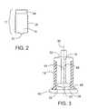
- FIG. 3is a perspective view of a preferred embodiment of the housing and plunger.
- FIG. 4is a perspective view of another preferred embodiment of the medical infusion and aspiration device.
- FIG. 5is a perspective view of a third preferred embodiment of the medical infusion and aspiration device.
- FIG. 6is a perspective view of a fourth preferred embodiment of the medical infusion and aspiration device.
- FIG. 7is a perspective view of a fifth preferred embodiment of the medical infusion and aspiration device.
- FIG. 8is a perspective view of an embodiment of the medical infusion and aspiration system having two cassettes being driven independently.
- FIG. 9is a perspective view of an embodiment of the medical infusion and aspiration system having two cassettes coupled by mechanical linkage.
- the present inventionis a medical infusion and aspiration system capable of accurate pulsatile delivery at high rates of flow.
- the present inventionprovides a means to automatically avoid errors in concentration, reagent and medicine type, and avoids the problems of shear and other medicine degrading pressure problems.
- the systemalso avoids the slip-stick, chatter, overruns, and the problem of hysteresis by breaking the seating forces in a lateral motion that does not vary the delivery profile by the viscosity of the reagent.
- the systemalso avoids loss of reagent in the priming of a separate infusion device and eliminates the tendency of reagents to separate when in a diluted environment.
- the inventionis disposable, inexpensive and may be used by the manufacturer in glass lined or plastic, as both the pumping cartridge and the shipping and storage cartridge.
- the current inventionalso eliminates the need for withdrawing the medicine with a needle and achieves extraordinary accuracy without error correcting software or expensive volumetric measurement and control systems.
- the current inventioncomprises a cassette cartridge pumping and aspirating device.
- the cassette cartridge pumping and aspiration systemconsisting of a cartridge, a housing, a plunger, a reservoir area where the reagent is contained, a neck opening for the connection of the cartridge to a tube which travels to where the infusion takes place, and an in-line area where probes for sampling are located.
- the in-line area probesare used to provide input to a pumping device.
- the current inventionhas only one moving part in relation to the delivery mechanism and this simplicity allows for more accuracy and lower costs. It also allows for a single handed adaption of the cassette to the pumping device, freeing the other hand and avoiding accidental sticking with “sharps” such as needles which may be contaminated with blood or other materials.
- FIG. 1is a perspective view of an embodiment of the invention showing a cassette 10 , a pumping mechanism 20 and a motor 30 .
- the cassettefurther comprises a cartridge 12 , a housing 14 , and a plunger 16 .
- the cartridge 12is cylindrical in shape and has a reservoir area 18 , a neck opening 22 and encoded area 24 .
- the cartridge 12is preferably made from glass or plastic.
- the cartridge 12be made of steel or ceramics.
- the outer surface of the cartridgebe threaded 26 . Any standard or metric thread size may be used.
- the reservoir area 18is preferably used for containing a reagent.
- the reservoir area 18may be pre-filled, thereby enabling the seller to market pre-filled reagent cartridges.
- the preferred embodimenteliminates expensive residue that is thrown away with the transportation bottle, as pre-filling allows for no waste. Pumps which may be re-inserted can store the unused reagent for an appropriate period of time in the cassette.
- the neck opening 22is preferably located at the bottom surface of the cartridge 12 .
- the neck opening 22is preferably sized to connect an infusion tube 28 to the cartridge 12 .
- Any conventional tube connection devicemay be used to connect the infusion tube 28 to the cartridge 12 .
- the opposite end of the infusion tube 28is connected to a vein 90 .
- the cartridge 12also contain a cap and container top which allows the cartridge 12 to act as the storage vessel for the reagent, and thereby avoid additional steps of filling, mixing, measuring or wasting reagent in the handling of the fluid.
- an optical or electromagnetic stripis located within an encoded area 24 on the cartridge 12 .
- an optical or electromagnetic strip with information on the contents and uses of the reagentis placed in the encoded area 24 .
- the encoded area 24is preferably located on the outer surface of the cartridge 12 in the area that is first inserted the housing 14 .
- optical reading of a bar code or other reading of the encoded area 24will minimize dosage mistakes, as each cartridge can set the maximum allowable dose or delivery.
- the rotational actioncauses the encoded area 24 to be well aligned and easily read with the uniform motion of screwing the cartridge 12 into place.
- the preferred rotation, pre-determined position of the encoded area 24 , and the ease of programming a unique character to each cartridge 12allows the reagent to be mistake limiting.
- the preferred embodiment systemrequires a weight to be entered into a pumping device 40 for each patient, thus greatly reducing the incidence of errors. Any conventional method of storing and retrieving data from the encoded area are preferably included in the present system to limit the incidence of errors.
- the encoded area 24comes into close proximity with a reading system as the cartridge 12 is loaded or is first used.
- the reading systemmay be any commercially available system capable of reading the encoded area 24 .
- a medical devicestores and uses the encoded information in its operations, including a means to limit the profile of the infusion allowed without further intentional override of the profile.
- the housing 14consists of a cylindrical tube that is sealed at the upper end, as shown in FIG. 3 .
- the housing 14is preferably made of plastic, however, any suitable commercially available material may be used.
- the bottom 38 of the housingis preferably open and the inner surface 42 of the housing is threaded. Any standard or metric thread size may be used.
- a plunger 16is preferably connected to the sealed end 50 and is suspended in alignment with the central axis 36 of housing 14 .
- the housing 14is sized to threadedly receive the cartridge 12 .
- the plurality of openings 44also creates an inspection window 46 within the housing 14 .
- the inspection window 46also allows access to the optical or electromagnetic strip within the encoded area 24 .
- a lip 48 at the bottom 38 of the housing 14provide for a manually removable protective cap 60 used to protect the cartridge from contamination or damage to the plunger 16 .
- the housing 14may be made in a clamshell or disassembled manner for easy withdrawal.
- the cartridge 12When the cartridge 12 is engaged in the housing 14 , the cartridge 12 is locked into place by the rotational engagement of the threads 26 , 42 .
- the locking of the meshed threadsmakes an accidental infusion by dropping or pressing on the plunger virtually impossible.
- the cartridge 12will not siphon out of the pump, or accidentally deliver fluid when dropped or pushed against.
- the preferred plunger 16is a piston-type plunger and is made from plastic, however, any type of non-reactive material may be used.
- the plunger 16is preferably connected to the sealed end 50 of the housing 14 and is aligned with the central axis of the housing.
- the plunger head 52is preferable sized to fit within the reservoir area 18 , so there is very little dead space thus resulting in very little loss of reagent in the final stroke or at the end of treatment.
- the plunger 16 and reservoir area 18 configurationmay have a larger diameter in relationship to the depth the plunger travels, or a very small diameter and longer plunger travel, depending upon the flow characteristics desired for the application. In very viscous fluids, a different diameter would be helpful for both storage and delivery reasons.
- a pumping mechanism 20is used to rotate the plunger 16 within the cassette 10 .
- the pumping mechanism 20comprises a gear linkage 54 , a motor 30 and a pumping device 40 .
- the pumping mechanism 20may be actuated by any motor which rotably moves the plunger 16 or housing 14 .
- the present inventionallows for direct drive, stepper motor, spring or band action motor, or hand articulation to deliver the desired plunger rotation.
- the “motor”may also be a coordinated hand-eye movement or movement to a series of “click” points.
- the plunger 16rotates in relation to the walls of the cassette housing 14 .
- a motor 30 with either electromechanical or mechanical operationis attached to the gear or drive which in turn causes a rotation of the plunger 16 and both lateral and axial movement of the plunger 16 .
- the motor 30is controlled by predetermined settings which may be inputted into a pumping device by the operator to cause the pumping and aspiration actions to take place as desired.
- the settingsmay be made by a spring-like mechanism, with the number of turns and speed of the mechanism being governed by a simple clock mechanism.
- the design of the motor 30 and assemblyallow the pump mechanism 20 to be put above, at, or below the heart level, with no resulting change in the delivery profile. This allows the pump mechanism 20 to be worn or enclosed in several different tamper-proof or patient access limiting configurations.
- the planes formed by the inner surface 42 of the housing and the outer surface 26 of the cartridgeare positioned so as to allow the plunger 16 to begin turning as it is first attached, or after it is attached to the cassette housing 14 .
- the plunger 16may extend beyond the line of the housing 14 for purposes of easy snap-in connection and alignment of the cassette 10 .
- the number of turns per meter or inchare adjusted to provide the desired rate of flow in both directions.
- the diameter of the cassette and its separate housingare adjusted to provide different flow rates and to adjust for any necessary fluid dynamics which might be necessary to pump highly viscous liquids or pump fluids at high flow rates.
- the deviceinfuses or aspirates liquid, depending on the rotational direction of the plunger.
- the rotational movement of the present inventionallows for bi-directional movement and provides accurate infusion or aspiration.
- FIG. 4shows an alternate embodiment of the cassette 10 .
- the cassette 10has only one opening, wherein the plunger 16 also acts as the locking system to the infusion tube 28 .
- a standard lure lock attachmentbe included in the plunger as a single piece.
- a protective cap 60is shown removed from the single piece cassette.
- Splines 62 on the side of the cassette 10mesh with the gearing mechanism driven by the motor 30 , all of which are attached to the pumping device 40 .
- the motor 30rotates the cassette 10 by attachment to splines 62 on the side, with the housing 14 fixed to the pumping device.
- the plunger 16then rotates, due to the lands and groves meshed between the housing 14 and cartridge 12 .
- FIG. 5shows another embodiment of the present invention.
- a direct screwing system 64 interfaceis attached to the side of the cassette 10 .
- the direct screwing system 64accomplishes the rotational and axial movement required to provide the delivery profile, as well as an internal rotational drive which automatically causes the plunger 16 to turn as the motor advances the plunger 16 upwards and downwards in order to infuse or aspirate.
- FIG. 6shows a fourth embodiment of the present invention.
- FIG. 6shows a rack 66 threaded surface, which allows the motor 30 , when placed adjacent to the rack 66 , to turn the housing 14 .
- the plunger 16remains stationary in relation to the motor 30 and rack 66 , thereby causing the plunger 16 to move rotationally in reference to the cassette 10 .
- the plunger sanction 68may swing away for easy snap-in and snap-out action.
- FIG. 7shows a fifth preferred embodiment of the present invention.
- FIG. 7shows a side screw 82 configuration for the cassette.
- the cartridge 12when placed in the housing 14 , causes the piston plunger 16 to move both forward and aft to aspirate or infuse, as well as rotate within the cassette 10 to break the forces of inertia and slip-stick as well as eliminate backlash. Because the device avoids slip-stick, chatter and the forces of hysteresis, and has no gates or valves, it is designed to also be used in a bi-directional application, such as one of the preferred embodiments herein, where the precise amount being withdrawn may be distributed, equally or in successive steps of precise delivery, or the precise amount withdrawn re-inserted into the patient to the “zero” point.
- a sensor area 70is located within the infusion tube 28 .
- the sensor area 70contains probes 72 designed to determine the chemical components and levels of desired substrates in the aspirated fluids.
- the information obtained by the probes 72relayed to the pumping device 40 and is used to control or limit the infusion profile.
- the probeswere made of electromagnetic material, however any probe capable of relaying information to the pumping device may be used.
- the bi-directional accuracy of the present inventionallows the system to be used with any number of probes. It is preferable that the probes measure the properties of a sample, such as blood, and then allow the prevent invention to re-infuse that sample back into the patient after it has been tested, or if desired, by second flow direction, deposit that blood into a separate container or depository.
- a samplesuch as blood
- the present inventionalso includes a pumping device 40 .
- the pumping device 40preferably has one, two, three or more sources of input.
- the preferred pumping deviceincludes, but is not limited to, an input system to drive the device 74 , a sensor input for in-line measurement of substrates 76 , an in-line occlusion pressure sensing system 78 and/or input from the reading of the encoded area 80 .
- the sensor input 76receives signals from the in-line sensor probes 72 .
- the in-line occlusion pressure sensing system 78determines the line pressure or back pressure on the motor.
- Other traditional pump featuresare intended to be incorporated into the pumping device 40 .
- the Rotational Velocityexceeds the Axial Velocity, although with sufficient diameter the difference in Rotational travel to Axial travel could be adjusted for the flow characteristics of the fluid to be infused and aspirated.
- a second cassette and housingmay be coupled and driven either independently or in mechanical linkage 80 with a cassette housing so as to have as many infusion profiles, either in succession or concurrently as is desired for the given flow profiles and applications, as shown in FIGS. 8 and 9.
- the cartridgeis also the pumping system, each time the cartridge is used, it is replaced, and the entire wearing aspects of the pumping system are replaced, thereby causing the product life cycles to be much greater.
- the entire fluid handling systemis replaced with each use and sterilization and cleaning of parts is eliminated.
- the purpose of the present inventionis to provide a system of quantitative chronoendocrinology, a term coined by the inventor.
- the apparent benefit to having pulses of almost any medicine, as an additional means for delivery,was deemed by the Inventors to be a valid approach to medical infusion for any and perhaps all forms of infusion therapy.
- Part of the invention claimedis the use of the device in sequence of infusions which, while in the aggregate the amount medicine used is less, but by virtue of he pulses, accomplishes additional medical results.
Landscapes
- Health & Medical Sciences (AREA)
- Vascular Medicine (AREA)
- Engineering & Computer Science (AREA)
- Anesthesiology (AREA)
- Biomedical Technology (AREA)
- Heart & Thoracic Surgery (AREA)
- Hematology (AREA)
- Life Sciences & Earth Sciences (AREA)
- Animal Behavior & Ethology (AREA)
- General Health & Medical Sciences (AREA)
- Public Health (AREA)
- Veterinary Medicine (AREA)
- Infusion, Injection, And Reservoir Apparatuses (AREA)
Abstract
Description
Claims (17)
Priority Applications (1)
| Application Number | Priority Date | Filing Date | Title |
|---|---|---|---|
| US09/881,828US6565535B2 (en) | 2000-06-16 | 2001-06-15 | Medical infusion and aspiration system |
Applications Claiming Priority (2)
| Application Number | Priority Date | Filing Date | Title |
|---|---|---|---|
| US21213400P | 2000-06-16 | 2000-06-16 | |
| US09/881,828US6565535B2 (en) | 2000-06-16 | 2001-06-15 | Medical infusion and aspiration system |
Publications (2)
| Publication Number | Publication Date |
|---|---|
| US20020007139A1 US20020007139A1 (en) | 2002-01-17 |
| US6565535B2true US6565535B2 (en) | 2003-05-20 |
Family
ID=26906807
Family Applications (1)
| Application Number | Title | Priority Date | Filing Date |
|---|---|---|---|
| US09/881,828Expired - Fee RelatedUS6565535B2 (en) | 2000-06-16 | 2001-06-15 | Medical infusion and aspiration system |
Country Status (1)
| Country | Link |
|---|---|
| US (1) | US6565535B2 (en) |
Cited By (75)
| Publication number | Priority date | Publication date | Assignee | Title |
|---|---|---|---|---|
| US20030114836A1 (en)* | 2001-12-19 | 2003-06-19 | Estes Mark C. | Medication delivery system and monitor |
| US20030217986A1 (en)* | 2002-05-24 | 2003-11-27 | Rudolf Sidler | Ampoule and administering device |
| EP1593403A1 (en)* | 2004-05-06 | 2005-11-09 | Bionica International NV | Medical device for quantitatively and chronologically sequenced infusion delivery |
| WO2006022906A1 (en)* | 2004-08-18 | 2006-03-02 | Gregory Ford Gilbert | Quantitative chronological medical infusion device |
| US20070077152A1 (en)* | 2005-09-30 | 2007-04-05 | Sherwood Services Ag | Aliquot correction for feeding set degradation |
| US20070088269A1 (en)* | 2005-09-30 | 2007-04-19 | Sherwood Services Ag | Medical pump with lockout system |
| US20070197978A1 (en)* | 2006-02-17 | 2007-08-23 | Leon Wortham | Drug Delivery Device |
| JP2008272503A (en)* | 2002-03-29 | 2008-11-13 | Thomas Takemi Aoki | Device for infusing insulin |
| US7530968B2 (en) | 2003-04-23 | 2009-05-12 | Valeritas, Inc. | Hydraulically actuated pump for long duration medicament administration |
| US20090177171A1 (en)* | 2008-01-04 | 2009-07-09 | Edge Systems Corporation | Apparatus and method for treating the skin |
| US20090192442A1 (en)* | 2008-01-29 | 2009-07-30 | Edge Systems Corporation | Apparatus and method for treating the skin |
| US7615007B2 (en) | 2006-10-04 | 2009-11-10 | Dexcom, Inc. | Analyte sensor |
| US7640048B2 (en) | 2004-07-13 | 2009-12-29 | Dexcom, Inc. | Analyte sensor |
| WO2010021951A2 (en) | 2008-08-18 | 2010-02-25 | The Brigham And Women's Hospital, Inc. | Integrated surgical sampling probe |
| US20100130958A1 (en)* | 2008-11-26 | 2010-05-27 | David Kang | Device and Methods for Subcutaneous Delivery of High Viscosity Fluids |
| US7783333B2 (en) | 2004-07-13 | 2010-08-24 | Dexcom, Inc. | Transcutaneous medical device with variable stiffness |
| WO2011006009A1 (en)* | 2009-07-08 | 2011-01-13 | Edge Systems Corporation | Devices, systems and methods for treating the skin using time-release substances |
| US20110022007A1 (en)* | 2008-05-07 | 2011-01-27 | Zhigang Li | Ophthalmic devices for the controlled release of active agents |
| US7885697B2 (en) | 2004-07-13 | 2011-02-08 | Dexcom, Inc. | Transcutaneous analyte sensor |
| US7914499B2 (en) | 2006-03-30 | 2011-03-29 | Valeritas, Inc. | Multi-cartridge fluid delivery device |
| US20110238037A1 (en)* | 2010-03-19 | 2011-09-29 | Chorng-Fure Robin Hwang | Gas-pressured medication delivery device |
| US20120130236A1 (en)* | 2010-11-24 | 2012-05-24 | Acist Medical Systems, Inc. | Contrast media injector syringe inlet valve system |
| US8275438B2 (en) | 2006-10-04 | 2012-09-25 | Dexcom, Inc. | Analyte sensor |
| US8287453B2 (en) | 2003-12-05 | 2012-10-16 | Dexcom, Inc. | Analyte sensor |
| US8298142B2 (en) | 2006-10-04 | 2012-10-30 | Dexcom, Inc. | Analyte sensor |
| US8364231B2 (en) | 2006-10-04 | 2013-01-29 | Dexcom, Inc. | Analyte sensor |
| US8364230B2 (en) | 2006-10-04 | 2013-01-29 | Dexcom, Inc. | Analyte sensor |
| US8396528B2 (en) | 2008-03-25 | 2013-03-12 | Dexcom, Inc. | Analyte sensor |
| US8425416B2 (en) | 2006-10-04 | 2013-04-23 | Dexcom, Inc. | Analyte sensor |
| US8425417B2 (en) | 2003-12-05 | 2013-04-23 | Dexcom, Inc. | Integrated device for continuous in vivo analyte detection and simultaneous control of an infusion device |
| US8447376B2 (en) | 2006-10-04 | 2013-05-21 | Dexcom, Inc. | Analyte sensor |
| US8449464B2 (en) | 2006-10-04 | 2013-05-28 | Dexcom, Inc. | Analyte sensor |
| US8478377B2 (en) | 2006-10-04 | 2013-07-02 | Dexcom, Inc. | Analyte sensor |
| US8562558B2 (en) | 2007-06-08 | 2013-10-22 | Dexcom, Inc. | Integrated medicament delivery device for use with continuous analyte sensor |
| US8562528B2 (en) | 2006-10-04 | 2013-10-22 | Dexcom, Inc. | Analyte sensor |
| US8626257B2 (en) | 2003-08-01 | 2014-01-07 | Dexcom, Inc. | Analyte sensor |
| US20140314594A1 (en)* | 2011-09-15 | 2014-10-23 | Oxford Nanopore Technologies Limited | Pump |
| US8886273B2 (en) | 2003-08-01 | 2014-11-11 | Dexcom, Inc. | Analyte sensor |
| US9089636B2 (en) | 2004-07-02 | 2015-07-28 | Valeritas, Inc. | Methods and devices for delivering GLP-1 and uses thereof |
| US9468464B2 (en) | 1999-08-26 | 2016-10-18 | Axia Medsciences, Llc | Methods for treating the skin using vacuum |
| US9474886B2 (en) | 2005-12-30 | 2016-10-25 | Edge Systems Llc | Removable tips for skin treatment systems |
| US9498610B2 (en) | 2014-12-23 | 2016-11-22 | Edge Systems Llc | Devices and methods for treating the skin using a rollerball or a wicking member |
| US9566088B2 (en) | 2006-03-29 | 2017-02-14 | Edge Systems Llc | Devices, systems and methods for treating the skin |
| US9593370B2 (en) | 2010-10-01 | 2017-03-14 | Oxford Nanopore Technologies Ltd. | Biochemical analysis apparatus and rotary valve |
| US9986942B2 (en) | 2004-07-13 | 2018-06-05 | Dexcom, Inc. | Analyte sensor |
| US10054234B2 (en) | 2011-07-13 | 2018-08-21 | Oxford Nanopore Technologies Limited | One-way valve |
| US10172644B2 (en) | 2006-03-29 | 2019-01-08 | Edge Systems Llc | Devices, systems and methods for treating the skin |
| US10179229B2 (en) | 2014-12-23 | 2019-01-15 | Edge Systems Llc | Devices and methods for treating the skin using a porous member |
| US10238812B2 (en) | 2013-03-15 | 2019-03-26 | Edge Systems Llc | Skin treatment systems and methods using needles |
| US10376687B2 (en) | 2012-10-16 | 2019-08-13 | Acist Medical Systems, Inc. | Controlling flow in a medical injection system |
| US10610137B2 (en) | 2005-03-10 | 2020-04-07 | Dexcom, Inc. | System and methods for processing analyte sensor data for sensor calibration |
| US10813577B2 (en) | 2005-06-21 | 2020-10-27 | Dexcom, Inc. | Analyte sensor |
| US10835672B2 (en) | 2004-02-26 | 2020-11-17 | Dexcom, Inc. | Integrated insulin delivery system with continuous glucose sensor |
| US10966609B2 (en) | 2004-02-26 | 2021-04-06 | Dexcom, Inc. | Integrated medicament delivery device for use with continuous analyte sensor |
| US10980461B2 (en) | 2008-11-07 | 2021-04-20 | Dexcom, Inc. | Advanced analyte sensor calibration and error detection |
| US10993743B2 (en) | 2013-03-15 | 2021-05-04 | Edge Systems Llc | Devices, systems and methods for treating the skin |
| US11000215B1 (en) | 2003-12-05 | 2021-05-11 | Dexcom, Inc. | Analyte sensor |
| US11071816B2 (en) | 2017-10-04 | 2021-07-27 | Johnson & Johnson Surgical Vision, Inc. | System, apparatus and method for monitoring anterior chamber intraoperative intraocular pressure |
| US11241357B2 (en) | 2015-07-08 | 2022-02-08 | Edge Systems Llc | Devices, systems and methods for promoting hair growth |
| US11246990B2 (en) | 2004-02-26 | 2022-02-15 | Dexcom, Inc. | Integrated delivery device for continuous glucose sensor |
| US11331022B2 (en) | 2017-10-24 | 2022-05-17 | Dexcom, Inc. | Pre-connected analyte sensors |
| US11350862B2 (en) | 2017-10-24 | 2022-06-07 | Dexcom, Inc. | Pre-connected analyte sensors |
| US11383020B2 (en) | 2017-10-04 | 2022-07-12 | Johnson & Johnson Surgical Vision, Inc. | System and method to augment irrigation pressure and to maintain IOP during post occlusion surge |
| US11399745B2 (en) | 2006-10-04 | 2022-08-02 | Dexcom, Inc. | Dual electrode system for a continuous analyte sensor |
| US11446424B2 (en) | 2017-10-04 | 2022-09-20 | Johnson & Johnson Surgical Vision, Inc. | Systems and methods for measuring fluid flow in a venturi based system |
| US11560964B2 (en) | 2020-08-21 | 2023-01-24 | Acist Medical Systems, Inc. | Valve actuation device coupling |
| US11633133B2 (en) | 2003-12-05 | 2023-04-25 | Dexcom, Inc. | Dual electrode system for a continuous analyte sensor |
| USD1016615S1 (en) | 2021-09-10 | 2024-03-05 | Hydrafacial Llc | Container for a skin treatment device |
| US11969380B2 (en) | 2017-10-04 | 2024-04-30 | Johnson & Johnson Surgical Vision, Inc. | Advanced occlusion management methods for a phacoemulsification system |
| US11998716B2 (en) | 2020-01-30 | 2024-06-04 | Acist Medical Systems, Inc. | Valve assembly |
| USD1042807S1 (en) | 2021-10-11 | 2024-09-17 | Hydrafacial Llc | Skin treatment tip |
| USD1065551S1 (en) | 2021-09-10 | 2025-03-04 | Hydrafacial Llc | Skin treatment device |
| US12285360B2 (en) | 2020-12-22 | 2025-04-29 | Johnson & Johnson Surgical Vision, Inc. | Reducing irrigation/aspiration valve response time in a phacoemulsification system |
| US12295618B2 (en) | 2020-01-06 | 2025-05-13 | Hydrafacial Llc | Skin treatment tool applicator tip |
| USD1084369S1 (en) | 2023-02-10 | 2025-07-15 | Hydrafacial Llc | Skin treatment tip |
Families Citing this family (3)
| Publication number | Priority date | Publication date | Assignee | Title |
|---|---|---|---|---|
| WO2005069831A2 (en)* | 2004-01-12 | 2005-08-04 | Iscience Surgical Corporation | Injector for viscous materials |
| DE102009012449A1 (en)* | 2009-03-12 | 2010-09-16 | Imp Pape Gmbh & Co. Kg | Method and device for continuously driving a syringe plunger |
| CN110051893B (en)* | 2019-05-22 | 2024-04-26 | 雅安市人民医院 | Gun type aspirator for treating echinococcosis |
Citations (12)
| Publication number | Priority date | Publication date | Assignee | Title |
|---|---|---|---|---|
| US4435173A (en)* | 1982-03-05 | 1984-03-06 | Delta Medical Industries | Variable rate syringe pump for insulin delivery |
| US4978335A (en)* | 1989-09-29 | 1990-12-18 | Medex, Inc. | Infusion pump with bar code input to computer |
| US5317506A (en)* | 1989-01-30 | 1994-05-31 | Abbott Laboratories | Infusion fluid management system |
| US5531679A (en)* | 1994-03-14 | 1996-07-02 | Schulman; Joseph H. | Fluidic infusion system for catheter or probe |
| US5800405A (en)* | 1995-12-01 | 1998-09-01 | I-Flow Corporation | Syringe actuation device |
| US5882338A (en)* | 1993-05-04 | 1999-03-16 | Zeneca Limited | Syringes and syringe pumps |
| US5954689A (en)* | 1996-12-20 | 1999-09-21 | Novo Nordisk A/S | Jet injector |
| US6248093B1 (en)* | 1998-10-29 | 2001-06-19 | Minimed Inc. | Compact pump drive system |
| US6269340B1 (en)* | 1992-10-15 | 2001-07-31 | The General Hospital | Infusion pump with an electronically loadable drug library and a user interface for loading the library |
| US6387077B1 (en)* | 2000-10-13 | 2002-05-14 | Mallinckrodt Inc. | Apparatus and method for providing a suspended agent |
| US6406455B1 (en)* | 1998-12-18 | 2002-06-18 | Biovalve Technologies, Inc. | Injection devices |
| US6423035B1 (en)* | 1999-06-18 | 2002-07-23 | Animas Corporation | Infusion pump with a sealed drive mechanism and improved method of occlusion detection |
- 2001
- 2001-06-15USUS09/881,828patent/US6565535B2/ennot_activeExpired - Fee Related
Patent Citations (12)
| Publication number | Priority date | Publication date | Assignee | Title |
|---|---|---|---|---|
| US4435173A (en)* | 1982-03-05 | 1984-03-06 | Delta Medical Industries | Variable rate syringe pump for insulin delivery |
| US5317506A (en)* | 1989-01-30 | 1994-05-31 | Abbott Laboratories | Infusion fluid management system |
| US4978335A (en)* | 1989-09-29 | 1990-12-18 | Medex, Inc. | Infusion pump with bar code input to computer |
| US6269340B1 (en)* | 1992-10-15 | 2001-07-31 | The General Hospital | Infusion pump with an electronically loadable drug library and a user interface for loading the library |
| US5882338A (en)* | 1993-05-04 | 1999-03-16 | Zeneca Limited | Syringes and syringe pumps |
| US5531679A (en)* | 1994-03-14 | 1996-07-02 | Schulman; Joseph H. | Fluidic infusion system for catheter or probe |
| US5800405A (en)* | 1995-12-01 | 1998-09-01 | I-Flow Corporation | Syringe actuation device |
| US5954689A (en)* | 1996-12-20 | 1999-09-21 | Novo Nordisk A/S | Jet injector |
| US6248093B1 (en)* | 1998-10-29 | 2001-06-19 | Minimed Inc. | Compact pump drive system |
| US6406455B1 (en)* | 1998-12-18 | 2002-06-18 | Biovalve Technologies, Inc. | Injection devices |
| US6423035B1 (en)* | 1999-06-18 | 2002-07-23 | Animas Corporation | Infusion pump with a sealed drive mechanism and improved method of occlusion detection |
| US6387077B1 (en)* | 2000-10-13 | 2002-05-14 | Mallinckrodt Inc. | Apparatus and method for providing a suspended agent |
Cited By (207)
| Publication number | Priority date | Publication date | Assignee | Title |
|---|---|---|---|---|
| US9468464B2 (en) | 1999-08-26 | 2016-10-18 | Axia Medsciences, Llc | Methods for treating the skin using vacuum |
| US9775646B2 (en) | 1999-08-26 | 2017-10-03 | Axia Medsciences, Llc | Devices and systems for treating the skin using vacuum |
| US8500702B2 (en) | 2001-12-19 | 2013-08-06 | Medtronic Minimed, Inc. | Medication delivery system and monitor |
| US7837647B2 (en) | 2001-12-19 | 2010-11-23 | Medtronic Minimed, Inc. | Medication delivery system and monitor |
| US7651489B2 (en) | 2001-12-19 | 2010-01-26 | Medtronic Minimed, Inc. | Medication delivery system and monitor |
| US8012119B2 (en) | 2001-12-19 | 2011-09-06 | Medtronic Minimed, Inc. | Medication delivery system and monitor |
| US20030114836A1 (en)* | 2001-12-19 | 2003-06-19 | Estes Mark C. | Medication delivery system and monitor |
| US20050245904A1 (en)* | 2001-12-19 | 2005-11-03 | Medtronic Minimed Inc. | Medication delivery system and monitor |
| US7204823B2 (en)* | 2001-12-19 | 2007-04-17 | Medtronic Minimed, Inc. | Medication delivery system and monitor |
| US20070287985A1 (en)* | 2001-12-19 | 2007-12-13 | Estes Mark C | Medication delivery system and monitor |
| JP2008272503A (en)* | 2002-03-29 | 2008-11-13 | Thomas Takemi Aoki | Device for infusing insulin |
| US20070282294A1 (en)* | 2002-05-24 | 2007-12-06 | Disetronic Licensing Ag | Ampoule and Administering Device |
| US20030217986A1 (en)* | 2002-05-24 | 2003-11-27 | Rudolf Sidler | Ampoule and administering device |
| US9511187B2 (en) | 2003-04-23 | 2016-12-06 | Valeritas, Inc. | Hydraulically actuated pump for fluid administration |
| US9072828B2 (en) | 2003-04-23 | 2015-07-07 | Valeritas, Inc. | Hydraulically actuated pump for long duration medicament administration |
| US7530968B2 (en) | 2003-04-23 | 2009-05-12 | Valeritas, Inc. | Hydraulically actuated pump for long duration medicament administration |
| US11642456B2 (en) | 2003-04-23 | 2023-05-09 | Mannkind Corporation | Hydraulically actuated pump for fluid administration |
| US8070726B2 (en) | 2003-04-23 | 2011-12-06 | Valeritas, Inc. | Hydraulically actuated pump for long duration medicament administration |
| US9125983B2 (en) | 2003-04-23 | 2015-09-08 | Valeritas, Inc. | Hydraulically actuated pump for fluid administration |
| US10525194B2 (en) | 2003-04-23 | 2020-01-07 | Valeritas, Inc. | Hydraulically actuated pump for fluid administration |
| US10052055B2 (en) | 2003-08-01 | 2018-08-21 | Dexcom, Inc. | Analyte sensor |
| US8626257B2 (en) | 2003-08-01 | 2014-01-07 | Dexcom, Inc. | Analyte sensor |
| US8886273B2 (en) | 2003-08-01 | 2014-11-11 | Dexcom, Inc. | Analyte sensor |
| US8425417B2 (en) | 2003-12-05 | 2013-04-23 | Dexcom, Inc. | Integrated device for continuous in vivo analyte detection and simultaneous control of an infusion device |
| US11020031B1 (en) | 2003-12-05 | 2021-06-01 | Dexcom, Inc. | Analyte sensor |
| US8287453B2 (en) | 2003-12-05 | 2012-10-16 | Dexcom, Inc. | Analyte sensor |
| US11633133B2 (en) | 2003-12-05 | 2023-04-25 | Dexcom, Inc. | Dual electrode system for a continuous analyte sensor |
| US11000215B1 (en) | 2003-12-05 | 2021-05-11 | Dexcom, Inc. | Analyte sensor |
| US10835672B2 (en) | 2004-02-26 | 2020-11-17 | Dexcom, Inc. | Integrated insulin delivery system with continuous glucose sensor |
| US12226617B2 (en) | 2004-02-26 | 2025-02-18 | Dexcom, Inc. | Integrated delivery device for continuous glucose sensor |
| US11246990B2 (en) | 2004-02-26 | 2022-02-15 | Dexcom, Inc. | Integrated delivery device for continuous glucose sensor |
| US12115357B2 (en) | 2004-02-26 | 2024-10-15 | Dexcom, Inc. | Integrated delivery device for continuous glucose sensor |
| US10966609B2 (en) | 2004-02-26 | 2021-04-06 | Dexcom, Inc. | Integrated medicament delivery device for use with continuous analyte sensor |
| US12102410B2 (en) | 2004-02-26 | 2024-10-01 | Dexcom, Inc | Integrated medicament delivery device for use with continuous analyte sensor |
| WO2005107836A1 (en)* | 2004-05-06 | 2005-11-17 | Bionica International Nv | Quantitative chronological medical infusion device |
| EP1593403A1 (en)* | 2004-05-06 | 2005-11-09 | Bionica International NV | Medical device for quantitatively and chronologically sequenced infusion delivery |
| US9089636B2 (en) | 2004-07-02 | 2015-07-28 | Valeritas, Inc. | Methods and devices for delivering GLP-1 and uses thereof |
| US10799158B2 (en) | 2004-07-13 | 2020-10-13 | Dexcom, Inc. | Analyte sensor |
| US10813576B2 (en) | 2004-07-13 | 2020-10-27 | Dexcom, Inc. | Analyte sensor |
| US10918313B2 (en) | 2004-07-13 | 2021-02-16 | Dexcom, Inc. | Analyte sensor |
| US10709362B2 (en) | 2004-07-13 | 2020-07-14 | Dexcom, Inc. | Analyte sensor |
| US10932700B2 (en) | 2004-07-13 | 2021-03-02 | Dexcom, Inc. | Analyte sensor |
| US10524703B2 (en) | 2004-07-13 | 2020-01-07 | Dexcom, Inc. | Transcutaneous analyte sensor |
| US10980452B2 (en) | 2004-07-13 | 2021-04-20 | Dexcom, Inc. | Analyte sensor |
| US10709363B2 (en) | 2004-07-13 | 2020-07-14 | Dexcom, Inc. | Analyte sensor |
| US10993642B2 (en) | 2004-07-13 | 2021-05-04 | Dexcom, Inc. | Analyte sensor |
| US10993641B2 (en) | 2004-07-13 | 2021-05-04 | Dexcom, Inc. | Analyte sensor |
| US9986942B2 (en) | 2004-07-13 | 2018-06-05 | Dexcom, Inc. | Analyte sensor |
| US11064917B2 (en) | 2004-07-13 | 2021-07-20 | Dexcom, Inc. | Analyte sensor |
| US10799159B2 (en) | 2004-07-13 | 2020-10-13 | Dexcom, Inc. | Analyte sensor |
| US7640048B2 (en) | 2004-07-13 | 2009-12-29 | Dexcom, Inc. | Analyte sensor |
| US10918315B2 (en) | 2004-07-13 | 2021-02-16 | Dexcom, Inc. | Analyte sensor |
| US10722152B2 (en) | 2004-07-13 | 2020-07-28 | Dexcom, Inc. | Analyte sensor |
| US11026605B1 (en) | 2004-07-13 | 2021-06-08 | Dexcom, Inc. | Analyte sensor |
| US10827956B2 (en) | 2004-07-13 | 2020-11-10 | Dexcom, Inc. | Analyte sensor |
| US11045120B2 (en) | 2004-07-13 | 2021-06-29 | Dexcom, Inc. | Analyte sensor |
| US7885697B2 (en) | 2004-07-13 | 2011-02-08 | Dexcom, Inc. | Transcutaneous analyte sensor |
| US7783333B2 (en) | 2004-07-13 | 2010-08-24 | Dexcom, Inc. | Transcutaneous medical device with variable stiffness |
| US8750955B2 (en) | 2004-07-13 | 2014-06-10 | Dexcom, Inc. | Analyte sensor |
| US9414777B2 (en) | 2004-07-13 | 2016-08-16 | Dexcom, Inc. | Transcutaneous analyte sensor |
| US8792953B2 (en) | 2004-07-13 | 2014-07-29 | Dexcom, Inc. | Transcutaneous analyte sensor |
| US8812072B2 (en) | 2004-07-13 | 2014-08-19 | Dexcom, Inc. | Transcutaneous medical device with variable stiffness |
| US7857760B2 (en) | 2004-07-13 | 2010-12-28 | Dexcom, Inc. | Analyte sensor |
| US11883164B2 (en) | 2004-07-13 | 2024-01-30 | Dexcom, Inc. | System and methods for processing analyte sensor data for sensor calibration |
| US10918314B2 (en) | 2004-07-13 | 2021-02-16 | Dexcom, Inc. | Analyte sensor |
| WO2006022906A1 (en)* | 2004-08-18 | 2006-03-02 | Gregory Ford Gilbert | Quantitative chronological medical infusion device |
| US20060079831A1 (en)* | 2004-08-18 | 2006-04-13 | Gilbert Gregory F | Quantitative chronological medical infusion device |
| US10925524B2 (en) | 2005-03-10 | 2021-02-23 | Dexcom, Inc. | System and methods for processing analyte sensor data for sensor calibration |
| US10898114B2 (en) | 2005-03-10 | 2021-01-26 | Dexcom, Inc. | System and methods for processing analyte sensor data for sensor calibration |
| US10856787B2 (en) | 2005-03-10 | 2020-12-08 | Dexcom, Inc. | System and methods for processing analyte sensor data for sensor calibration |
| US10918316B2 (en) | 2005-03-10 | 2021-02-16 | Dexcom, Inc. | System and methods for processing analyte sensor data for sensor calibration |
| US10918317B2 (en) | 2005-03-10 | 2021-02-16 | Dexcom, Inc. | System and methods for processing analyte sensor data for sensor calibration |
| US10918318B2 (en) | 2005-03-10 | 2021-02-16 | Dexcom, Inc. | System and methods for processing analyte sensor data for sensor calibration |
| US10743801B2 (en) | 2005-03-10 | 2020-08-18 | Dexcom, Inc. | System and methods for processing analyte sensor data for sensor calibration |
| US10610137B2 (en) | 2005-03-10 | 2020-04-07 | Dexcom, Inc. | System and methods for processing analyte sensor data for sensor calibration |
| US11051726B2 (en) | 2005-03-10 | 2021-07-06 | Dexcom, Inc. | System and methods for processing analyte sensor data for sensor calibration |
| US10716498B2 (en) | 2005-03-10 | 2020-07-21 | Dexcom, Inc. | System and methods for processing analyte sensor data for sensor calibration |
| US10709364B2 (en) | 2005-03-10 | 2020-07-14 | Dexcom, Inc. | System and methods for processing analyte sensor data for sensor calibration |
| US11000213B2 (en) | 2005-03-10 | 2021-05-11 | Dexcom, Inc. | System and methods for processing analyte sensor data for sensor calibration |
| US10617336B2 (en) | 2005-03-10 | 2020-04-14 | Dexcom, Inc. | System and methods for processing analyte sensor data for sensor calibration |
| US10610135B2 (en) | 2005-03-10 | 2020-04-07 | Dexcom, Inc. | System and methods for processing analyte sensor data for sensor calibration |
| US10610136B2 (en) | 2005-03-10 | 2020-04-07 | Dexcom, Inc. | System and methods for processing analyte sensor data for sensor calibration |
| US10813577B2 (en) | 2005-06-21 | 2020-10-27 | Dexcom, Inc. | Analyte sensor |
| US8360757B2 (en) | 2005-09-30 | 2013-01-29 | Covidien Ag | Aliquot correction for feeding set degradation |
| US20090191066A1 (en)* | 2005-09-30 | 2009-07-30 | Covidien Ag | Aliquot correction for feeding set degradation |
| US7534099B2 (en) | 2005-09-30 | 2009-05-19 | Covidien Ag | Aliquot correction for feeding set degradation |
| US20070088269A1 (en)* | 2005-09-30 | 2007-04-19 | Sherwood Services Ag | Medical pump with lockout system |
| US20070077152A1 (en)* | 2005-09-30 | 2007-04-05 | Sherwood Services Ag | Aliquot correction for feeding set degradation |
| US9662482B2 (en) | 2005-12-30 | 2017-05-30 | Edge Systems Llc | Methods and systems for extraction of materials from skin |
| US9474886B2 (en) | 2005-12-30 | 2016-10-25 | Edge Systems Llc | Removable tips for skin treatment systems |
| US11612726B2 (en) | 2005-12-30 | 2023-03-28 | Hydrafacial Llc | Devices and methods for treating skin |
| US12053607B2 (en) | 2005-12-30 | 2024-08-06 | Hydrafacial Llc | Devices and methods for treating skin |
| US11865287B2 (en) | 2005-12-30 | 2024-01-09 | Hydrafacial Llc | Devices and methods for treating skin |
| US9550052B2 (en) | 2005-12-30 | 2017-01-24 | Edge Systems Llc | Console system for the treatment of skin |
| US11446477B2 (en) | 2005-12-30 | 2022-09-20 | Hydrafacial Llc | Devices and methods for treating skin |
| US10357641B2 (en) | 2005-12-30 | 2019-07-23 | Edge Systems Llc | Tips for skin treatment device |
| US10357642B2 (en) | 2005-12-30 | 2019-07-23 | Edge Systems Llc | Removable tips for use with skin treatment systems |
| US9814868B2 (en) | 2005-12-30 | 2017-11-14 | Edge Systems Llc | Tip with embedded materials for skin treatment |
| US11547840B2 (en) | 2005-12-30 | 2023-01-10 | Hydrafacial Llc | Devices and methods for treating skin |
| US20070197978A1 (en)* | 2006-02-17 | 2007-08-23 | Leon Wortham | Drug Delivery Device |
| US10251675B2 (en) | 2006-03-29 | 2019-04-09 | Edge Systems Llc | Devices, systems and methods for treating the skin |
| US10172644B2 (en) | 2006-03-29 | 2019-01-08 | Edge Systems Llc | Devices, systems and methods for treating the skin |
| US11717326B2 (en) | 2006-03-29 | 2023-08-08 | Hydrafacial Llc | Devices, systems and methods for treating the skin |
| US9566088B2 (en) | 2006-03-29 | 2017-02-14 | Edge Systems Llc | Devices, systems and methods for treating the skin |
| US12246159B2 (en) | 2006-03-30 | 2025-03-11 | Mannkind Corporation | Multi-cartridge fluid delivery device |
| US9687599B2 (en) | 2006-03-30 | 2017-06-27 | Valeritas, Inc. | Multi-cartridge fluid delivery device |
| US10493199B2 (en) | 2006-03-30 | 2019-12-03 | Valeritas, Inc. | Multi-cartridge fluid delivery device |
| US8361053B2 (en) | 2006-03-30 | 2013-01-29 | Valeritas, Inc. | Multi-cartridge fluid delivery device |
| US7914499B2 (en) | 2006-03-30 | 2011-03-29 | Valeritas, Inc. | Multi-cartridge fluid delivery device |
| US8821443B2 (en) | 2006-03-30 | 2014-09-02 | Valeritas, Inc. | Multi-cartridge fluid delivery device |
| US8298142B2 (en) | 2006-10-04 | 2012-10-30 | Dexcom, Inc. | Analyte sensor |
| US8911367B2 (en) | 2006-10-04 | 2014-12-16 | Dexcom, Inc. | Analyte sensor |
| US8478377B2 (en) | 2006-10-04 | 2013-07-02 | Dexcom, Inc. | Analyte sensor |
| US8449464B2 (en) | 2006-10-04 | 2013-05-28 | Dexcom, Inc. | Analyte sensor |
| US8275438B2 (en) | 2006-10-04 | 2012-09-25 | Dexcom, Inc. | Analyte sensor |
| US8532730B2 (en) | 2006-10-04 | 2013-09-10 | Dexcom, Inc. | Analyte sensor |
| US7775975B2 (en) | 2006-10-04 | 2010-08-17 | Dexcom, Inc. | Analyte sensor |
| US7615007B2 (en) | 2006-10-04 | 2009-11-10 | Dexcom, Inc. | Analyte sensor |
| US8447376B2 (en) | 2006-10-04 | 2013-05-21 | Dexcom, Inc. | Analyte sensor |
| US11399745B2 (en) | 2006-10-04 | 2022-08-02 | Dexcom, Inc. | Dual electrode system for a continuous analyte sensor |
| US10349873B2 (en) | 2006-10-04 | 2019-07-16 | Dexcom, Inc. | Analyte sensor |
| US8562528B2 (en) | 2006-10-04 | 2013-10-22 | Dexcom, Inc. | Analyte sensor |
| US8364231B2 (en) | 2006-10-04 | 2013-01-29 | Dexcom, Inc. | Analyte sensor |
| US9451908B2 (en) | 2006-10-04 | 2016-09-27 | Dexcom, Inc. | Analyte sensor |
| US8364230B2 (en) | 2006-10-04 | 2013-01-29 | Dexcom, Inc. | Analyte sensor |
| US8774886B2 (en) | 2006-10-04 | 2014-07-08 | Dexcom, Inc. | Analyte sensor |
| US11382539B2 (en) | 2006-10-04 | 2022-07-12 | Dexcom, Inc. | Analyte sensor |
| US8425416B2 (en) | 2006-10-04 | 2013-04-23 | Dexcom, Inc. | Analyte sensor |
| US10403012B2 (en) | 2007-06-08 | 2019-09-03 | Dexcom, Inc. | Integrated medicament delivery device for use with continuous analyte sensor |
| US11373347B2 (en) | 2007-06-08 | 2022-06-28 | Dexcom, Inc. | Integrated medicament delivery device for use with continuous analyte sensor |
| US9741139B2 (en) | 2007-06-08 | 2017-08-22 | Dexcom, Inc. | Integrated medicament delivery device for use with continuous analyte sensor |
| US12394120B2 (en) | 2007-06-08 | 2025-08-19 | Dexcom, Inc. | Integrated medicament delivery device for use with continuous analyte sensor |
| US8562558B2 (en) | 2007-06-08 | 2013-10-22 | Dexcom, Inc. | Integrated medicament delivery device for use with continuous analyte sensor |
| US11160926B1 (en) | 2007-10-09 | 2021-11-02 | Dexcom, Inc. | Pre-connected analyte sensors |
| US12397110B2 (en) | 2007-10-09 | 2025-08-26 | Dexcom, Inc. | Integrated insulin delivery system with continuous glucose sensor |
| US12397113B2 (en) | 2007-10-09 | 2025-08-26 | Dexcom, Inc. | Integrated insulin delivery system with continuous glucose sensor |
| US12246166B2 (en) | 2007-10-09 | 2025-03-11 | Dexcom, Inc. | Integrated insulin delivery system with continuous glucose sensor |
| US11744943B2 (en) | 2007-10-09 | 2023-09-05 | Dexcom, Inc. | Integrated insulin delivery system with continuous glucose sensor |
| US10556096B2 (en) | 2008-01-04 | 2020-02-11 | Edge Systems Llc | Devices and methods for skin treatment |
| US11883621B2 (en) | 2008-01-04 | 2024-01-30 | Hydrafacial Llc | Devices and methods for skin treatment |
| US20090177171A1 (en)* | 2008-01-04 | 2009-07-09 | Edge Systems Corporation | Apparatus and method for treating the skin |
| US9486615B2 (en) | 2008-01-04 | 2016-11-08 | Edge Systems Llc | Microdermabrasion apparatus and method |
| US8343116B2 (en) | 2008-01-04 | 2013-01-01 | Edge Systems Corporation | Apparatus and method for treating the skin |
| US8814836B2 (en) | 2008-01-29 | 2014-08-26 | Edge Systems Llc | Devices, systems and methods for treating the skin using time-release substances |
| US10556097B2 (en) | 2008-01-29 | 2020-02-11 | Edge Systems Llc | Devices for treating skin using treatment materials located along a tip |
| US9642997B2 (en) | 2008-01-29 | 2017-05-09 | Edge Systems Llc | Devices for treating skin using treatment materials located along a tip |
| US12005217B2 (en) | 2008-01-29 | 2024-06-11 | Hydrafacial Llc | Devices, systems and methods for skin treatment |
| US11020577B2 (en) | 2008-01-29 | 2021-06-01 | Edge Systems Llc | Devices and systems for treating skin surfaces |
| US12161830B2 (en) | 2008-01-29 | 2024-12-10 | Hydrafacial Llc | Devices, systems, and methods for treating the skin |
| US12186513B2 (en) | 2008-01-29 | 2025-01-07 | Hydrafacial Llc | Devices, systems and methods for skin treatment |
| US20090192442A1 (en)* | 2008-01-29 | 2009-07-30 | Edge Systems Corporation | Apparatus and method for treating the skin |
| US9056193B2 (en) | 2008-01-29 | 2015-06-16 | Edge Systems Llc | Apparatus and method for treating the skin |
| US11896374B2 (en) | 2008-03-25 | 2024-02-13 | Dexcom, Inc. | Analyte sensor |
| US10602968B2 (en) | 2008-03-25 | 2020-03-31 | Dexcom, Inc. | Analyte sensor |
| US8396528B2 (en) | 2008-03-25 | 2013-03-12 | Dexcom, Inc. | Analyte sensor |
| US8377042B2 (en)* | 2008-05-07 | 2013-02-19 | Johnson & Johnson Vision Care, Inc. | Ophthalmic devices for the controlled release of active agents |
| US20110022007A1 (en)* | 2008-05-07 | 2011-01-27 | Zhigang Li | Ophthalmic devices for the controlled release of active agents |
| US20110144476A1 (en)* | 2008-08-18 | 2011-06-16 | The Brigham And Women's Hospital, Inc. | Integrated Surgical Sampling Probe |
| WO2010021951A2 (en) | 2008-08-18 | 2010-02-25 | The Brigham And Women's Hospital, Inc. | Integrated surgical sampling probe |
| US10980461B2 (en) | 2008-11-07 | 2021-04-20 | Dexcom, Inc. | Advanced analyte sensor calibration and error detection |
| US20100130958A1 (en)* | 2008-11-26 | 2010-05-27 | David Kang | Device and Methods for Subcutaneous Delivery of High Viscosity Fluids |
| WO2011006009A1 (en)* | 2009-07-08 | 2011-01-13 | Edge Systems Corporation | Devices, systems and methods for treating the skin using time-release substances |
| US20110238037A1 (en)* | 2010-03-19 | 2011-09-29 | Chorng-Fure Robin Hwang | Gas-pressured medication delivery device |
| US8551071B2 (en) | 2010-03-19 | 2013-10-08 | Halozyme, Inc. | Gas-pressured medication delivery device |
| US9593370B2 (en) | 2010-10-01 | 2017-03-14 | Oxford Nanopore Technologies Ltd. | Biochemical analysis apparatus and rotary valve |
| US10036065B2 (en) | 2010-10-01 | 2018-07-31 | Oxford Nanopore Technologies Limited | Biochemical analysis apparatus and rotary valve |
| US10322277B2 (en)* | 2010-11-24 | 2019-06-18 | Acist Medical Systems, Inc. | Contrast media injector syringe inlet valve system |
| US20120130236A1 (en)* | 2010-11-24 | 2012-05-24 | Acist Medical Systems, Inc. | Contrast media injector syringe inlet valve system |
| US10054234B2 (en) | 2011-07-13 | 2018-08-21 | Oxford Nanopore Technologies Limited | One-way valve |
| US9551338B2 (en)* | 2011-09-15 | 2017-01-24 | Oxford Nanopore Technologies Ltd. | Pump |
| US10342589B2 (en) | 2011-09-15 | 2019-07-09 | Oxford Nanopore Technologies Ltd. | Pump |
| US20140314594A1 (en)* | 2011-09-15 | 2014-10-23 | Oxford Nanopore Technologies Limited | Pump |
| US10596322B2 (en) | 2011-09-15 | 2020-03-24 | Oxford Nanopore Technologies Ltd. | Pump |
| US10675412B2 (en) | 2011-09-15 | 2020-06-09 | Oxford Nanopore Technologies Limited | Piston seal |
| US10376687B2 (en) | 2012-10-16 | 2019-08-13 | Acist Medical Systems, Inc. | Controlling flow in a medical injection system |
| US11517350B2 (en) | 2013-03-15 | 2022-12-06 | Hydrafacial Llc | Devices, systems and methods for treating the skin |
| US10993743B2 (en) | 2013-03-15 | 2021-05-04 | Edge Systems Llc | Devices, systems and methods for treating the skin |
| US10238812B2 (en) | 2013-03-15 | 2019-03-26 | Edge Systems Llc | Skin treatment systems and methods using needles |
| US11213321B2 (en) | 2013-03-15 | 2022-01-04 | Edge Systems Llc | Devices, systems and methods for treating the skin |
| US11202657B2 (en) | 2013-03-15 | 2021-12-21 | Edge Systems Llc | Devices, systems and methods for treating the skin |
| US11903615B2 (en) | 2013-03-15 | 2024-02-20 | Hydrafacial Llc | Devices, systems and methods for treating the skin |
| US9498610B2 (en) | 2014-12-23 | 2016-11-22 | Edge Systems Llc | Devices and methods for treating the skin using a rollerball or a wicking member |
| US10035007B2 (en) | 2014-12-23 | 2018-07-31 | Edge Systems Llc | Devices and methods for treating the skin |
| US11744999B2 (en) | 2014-12-23 | 2023-09-05 | Hydra Facial LLC | Devices and methods for treating the skin |
| US11925780B2 (en) | 2014-12-23 | 2024-03-12 | Hydrafacial Llc | Devices and methods for treating the skin |
| US10179229B2 (en) | 2014-12-23 | 2019-01-15 | Edge Systems Llc | Devices and methods for treating the skin using a porous member |
| US11806495B2 (en) | 2014-12-23 | 2023-11-07 | Hydrafacial Llc | Devices and methods for treating the skin |
| US11224728B2 (en) | 2014-12-23 | 2022-01-18 | Edge Systems Llc | Devices and methods for treating the skin using a porous member |
| US11241357B2 (en) | 2015-07-08 | 2022-02-08 | Edge Systems Llc | Devices, systems and methods for promoting hair growth |
| US11071816B2 (en) | 2017-10-04 | 2021-07-27 | Johnson & Johnson Surgical Vision, Inc. | System, apparatus and method for monitoring anterior chamber intraoperative intraocular pressure |
| US11383020B2 (en) | 2017-10-04 | 2022-07-12 | Johnson & Johnson Surgical Vision, Inc. | System and method to augment irrigation pressure and to maintain IOP during post occlusion surge |
| US11446424B2 (en) | 2017-10-04 | 2022-09-20 | Johnson & Johnson Surgical Vision, Inc. | Systems and methods for measuring fluid flow in a venturi based system |
| US11969380B2 (en) | 2017-10-04 | 2024-04-30 | Johnson & Johnson Surgical Vision, Inc. | Advanced occlusion management methods for a phacoemulsification system |
| US11706876B2 (en) | 2017-10-24 | 2023-07-18 | Dexcom, Inc. | Pre-connected analyte sensors |
| US11350862B2 (en) | 2017-10-24 | 2022-06-07 | Dexcom, Inc. | Pre-connected analyte sensors |
| US12150250B2 (en) | 2017-10-24 | 2024-11-19 | Dexcom, Inc. | Pre-connected analyte sensors |
| US11943876B2 (en) | 2017-10-24 | 2024-03-26 | Dexcom, Inc. | Pre-connected analyte sensors |
| US11331022B2 (en) | 2017-10-24 | 2022-05-17 | Dexcom, Inc. | Pre-connected analyte sensors |
| US11382540B2 (en) | 2017-10-24 | 2022-07-12 | Dexcom, Inc. | Pre-connected analyte sensors |
| US12295618B2 (en) | 2020-01-06 | 2025-05-13 | Hydrafacial Llc | Skin treatment tool applicator tip |
| US11998716B2 (en) | 2020-01-30 | 2024-06-04 | Acist Medical Systems, Inc. | Valve assembly |
| US11560964B2 (en) | 2020-08-21 | 2023-01-24 | Acist Medical Systems, Inc. | Valve actuation device coupling |
| US12285360B2 (en) | 2020-12-22 | 2025-04-29 | Johnson & Johnson Surgical Vision, Inc. | Reducing irrigation/aspiration valve response time in a phacoemulsification system |
| USD1065551S1 (en) | 2021-09-10 | 2025-03-04 | Hydrafacial Llc | Skin treatment device |
| USD1016615S1 (en) | 2021-09-10 | 2024-03-05 | Hydrafacial Llc | Container for a skin treatment device |
| USD1042807S1 (en) | 2021-10-11 | 2024-09-17 | Hydrafacial Llc | Skin treatment tip |
| USD1084369S1 (en) | 2023-02-10 | 2025-07-15 | Hydrafacial Llc | Skin treatment tip |
Also Published As
| Publication number | Publication date |
|---|---|
| US20020007139A1 (en) | 2002-01-17 |
Similar Documents
| Publication | Publication Date | Title |
|---|---|---|
| US6565535B2 (en) | Medical infusion and aspiration system | |
| WO2006022906A1 (en) | Quantitative chronological medical infusion device | |
| US20230144057A1 (en) | Rapid fluid delivery system | |
| EP2696915B1 (en) | Infusion pump device with re-filling scheme for cylinder-piston dosing unit | |
| US4332246A (en) | Positive displacement intravenous infusion pump device and method | |
| EP2696914B1 (en) | Infusion pump device with improved priming of the fluidic system and method for priming such an infusion pump device | |
| US20130172808A1 (en) | Medical infusion device producing adenosine triphosphate from carbohydrates | |
| US6063052A (en) | Injection system and pumping system for use therein | |
| EP2510960B1 (en) | Infusion pump device with cylinder-piston dosing unit and optical piston position detection | |
| EP0650739B1 (en) | Total system for contrast delivery | |
| US6645177B1 (en) | Directly engaged syringe driver system | |
| WO1996027399A1 (en) | Device of the controlled injection of a programmable quantity of liquid | |
| EP1593403A1 (en) | Medical device for quantitatively and chronologically sequenced infusion delivery | |
| EP0094998A1 (en) | Positive displacement intravenous infusion pump device and method | |
| JPH04501367A (en) | Pump for automatic and slow delivery of vials |
Legal Events
| Date | Code | Title | Description |
|---|---|---|---|
| AS | Assignment | Owner name:GREGORY F. GILBERT, CALIFORNIA Free format text:ASSIGNMENT OF ASSIGNORS INTEREST;ASSIGNOR:ZAIAS, NARDO;REEL/FRAME:014646/0469 Effective date:20030602 | |
| AS | Assignment | Owner name:CONNECTICUT INNOVATIONS, INCORPORATED, CONNECTICUT Free format text:ASSIGNMENT OF ASSIGNORS INTEREST;ASSIGNOR:BIONICA INC.;REEL/FRAME:016397/0579 Effective date:20050223 | |
| RF | Reissue application filed | Effective date:20050520 | |
| FPAY | Fee payment | Year of fee payment:4 | |
| FEPP | Fee payment procedure | Free format text:PAYOR NUMBER ASSIGNED (ORIGINAL EVENT CODE: ASPN); ENTITY STATUS OF PATENT OWNER: SMALL ENTITY | |
| FEPP | Fee payment procedure | Free format text:PETITION RELATED TO MAINTENANCE FEES FILED (ORIGINAL EVENT CODE: PMFP); ENTITY STATUS OF PATENT OWNER: SMALL ENTITY | |
| FEPP | Fee payment procedure | Free format text:PETITION RELATED TO MAINTENANCE FEES DISMISSED (ORIGINAL EVENT CODE: PMFS); ENTITY STATUS OF PATENT OWNER: SMALL ENTITY | |
| REMI | Maintenance fee reminder mailed | ||
| LAPS | Lapse for failure to pay maintenance fees | ||
| STCH | Information on status: patent discontinuation | Free format text:PATENT EXPIRED DUE TO NONPAYMENT OF MAINTENANCE FEES UNDER 37 CFR 1.362 | |
| FP | Lapsed due to failure to pay maintenance fee | Effective date:20110520 |