US6564806B1 - Device for accurately marking tissue - Google Patents
Device for accurately marking tissueDownload PDFInfo
- Publication number
- US6564806B1 US6564806B1US09/507,361US50736100AUS6564806B1US 6564806 B1US6564806 B1US 6564806B1US 50736100 AUS50736100 AUS 50736100AUS 6564806 B1US6564806 B1US 6564806B1
- Authority
- US
- United States
- Prior art keywords
- tissue
- locator element
- locator
- volume
- border
- Prior art date
- Legal status (The legal status is an assumption and is not a legal conclusion. Google has not performed a legal analysis and makes no representation as to the accuracy of the status listed.)
- Expired - Lifetime
Links
- 238000000034methodMethods0.000claimsabstractdescription101
- 230000000149penetrating effectEffects0.000claimsabstractdescription25
- 238000005520cutting processMethods0.000claimsdescription45
- 210000000481breastAnatomy0.000claimsdescription35
- 239000000463materialSubstances0.000claimsdescription27
- 230000004807localizationEffects0.000claimsdescription17
- 238000006073displacement reactionMethods0.000claimsdescription11
- 229910001000nickel titaniumInorganic materials0.000claimsdescription9
- 229910001220stainless steelInorganic materials0.000claimsdescription7
- 239000010935stainless steelSubstances0.000claimsdescription7
- HZEWFHLRYVTOIW-UHFFFAOYSA-N[Ti].[Ni]Chemical compound[Ti].[Ni]HZEWFHLRYVTOIW-UHFFFAOYSA-N0.000claimsdescription5
- 229910000639Spring steelInorganic materials0.000claimsdescription4
- 238000002595magnetic resonance imagingMethods0.000claimsdescription4
- 229920000249biocompatible polymerPolymers0.000claimsdescription3
- 239000012781shape memory materialSubstances0.000claimsdescription3
- 210000001519tissueAnatomy0.000description363
- 230000003902lesionEffects0.000description82
- 238000001574biopsyMethods0.000description13
- 230000037361pathwayEffects0.000description11
- 238000009413insulationMethods0.000description10
- 238000013459approachMethods0.000description8
- 238000007906compressionMethods0.000description7
- 208000004434CalcinosisDiseases0.000description6
- 230000008901benefitEffects0.000description6
- 239000011248coating agentSubstances0.000description6
- 238000000576coating methodMethods0.000description6
- 230000006835compressionEffects0.000description6
- 230000033001locomotionEffects0.000description6
- BASFCYQUMIYNBI-UHFFFAOYSA-NplatinumChemical compound[Pt]BASFCYQUMIYNBI-UHFFFAOYSA-N0.000description6
- 229910045601alloyInorganic materials0.000description5
- 239000000956alloySubstances0.000description5
- 239000003795chemical substances by applicationSubstances0.000description5
- 238000013461designMethods0.000description5
- 238000003384imaging methodMethods0.000description5
- 230000008569processEffects0.000description5
- 230000007704transitionEffects0.000description5
- 239000002131composite materialSubstances0.000description4
- 230000001788irregularEffects0.000description4
- 239000000314lubricantSubstances0.000description4
- 229910052751metalInorganic materials0.000description4
- 239000002184metalSubstances0.000description4
- 238000001356surgical procedureMethods0.000description4
- WFKWXMTUELFFGS-UHFFFAOYSA-NtungstenChemical compound[W]WFKWXMTUELFFGS-UHFFFAOYSA-N0.000description4
- 229910052721tungstenInorganic materials0.000description4
- 239000010937tungstenSubstances0.000description4
- 206010028980NeoplasmDiseases0.000description3
- 230000005540biological transmissionEffects0.000description3
- -1copper-zinc-aluminumChemical compound0.000description3
- 239000000835fiberSubstances0.000description3
- 239000003550markerSubstances0.000description3
- 150000002739metalsChemical class0.000description3
- HLXZNVUGXRDIFK-UHFFFAOYSA-Nnickel titaniumChemical compound[Ti].[Ti].[Ti].[Ti].[Ti].[Ti].[Ti].[Ti].[Ti].[Ti].[Ti].[Ni].[Ni].[Ni].[Ni].[Ni].[Ni].[Ni].[Ni].[Ni].[Ni].[Ni].[Ni].[Ni].[Ni]HLXZNVUGXRDIFK-UHFFFAOYSA-N0.000description3
- 210000000056organAnatomy0.000description3
- 229910052697platinumInorganic materials0.000description3
- 229920000642polymerPolymers0.000description3
- 206010006187Breast cancerDiseases0.000description2
- 208000026310Breast neoplasmDiseases0.000description2
- NNJVILVZKWQKPM-UHFFFAOYSA-NLidocaineChemical compoundCCN(CC)CC(=O)NC1=C(C)C=CC=C1CNNJVILVZKWQKPM-UHFFFAOYSA-N0.000description2
- KDLHZDBZIXYQEI-UHFFFAOYSA-NPalladiumChemical compound[Pd]KDLHZDBZIXYQEI-UHFFFAOYSA-N0.000description2
- RTAQQCXQSZGOHL-UHFFFAOYSA-NTitaniumChemical compound[Ti]RTAQQCXQSZGOHL-UHFFFAOYSA-N0.000description2
- 208000027418Wounds and injuryDiseases0.000description2
- 239000000853adhesiveSubstances0.000description2
- 230000001070adhesive effectEffects0.000description2
- TZCXTZWJZNENPQ-UHFFFAOYSA-Lbarium sulfateChemical compound[Ba+2].[O-]S([O-])(=O)=OTZCXTZWJZNENPQ-UHFFFAOYSA-L0.000description2
- 230000000740bleeding effectEffects0.000description2
- 238000005219brazingMethods0.000description2
- 201000011510cancerDiseases0.000description2
- 230000010261cell growthEffects0.000description2
- 229910017052cobaltInorganic materials0.000description2
- 239000010941cobaltSubstances0.000description2
- GUTLYIVDDKVIGB-UHFFFAOYSA-Ncobalt atomChemical compound[Co]GUTLYIVDDKVIGB-UHFFFAOYSA-N0.000description2
- 230000006378damageEffects0.000description2
- 230000034994deathEffects0.000description2
- 231100000517deathToxicity0.000description2
- 230000001419dependent effectEffects0.000description2
- 201000010099diseaseDiseases0.000description2
- 208000037265diseases, disorders, signs and symptomsDiseases0.000description2
- 230000001747exhibiting effectEffects0.000description2
- 239000003193general anesthetic agentSubstances0.000description2
- 238000011065in-situ storageMethods0.000description2
- 208000014674injuryDiseases0.000description2
- 238000005304joiningMethods0.000description2
- 229960004194lidocaineDrugs0.000description2
- 239000007788liquidSubstances0.000description2
- 210000004185liverAnatomy0.000description2
- 210000004072lungAnatomy0.000description2
- 238000005259measurementMethods0.000description2
- 230000007246mechanismEffects0.000description2
- 230000001394metastastic effectEffects0.000description2
- 206010061289metastatic neoplasmDiseases0.000description2
- 230000005012migrationEffects0.000description2
- 238000013508migrationMethods0.000description2
- 210000003205muscleAnatomy0.000description2
- 238000013188needle biopsyMethods0.000description2
- 239000004033plasticSubstances0.000description2
- 239000002243precursorSubstances0.000description2
- 238000007493shaping processMethods0.000description2
- 238000005476solderingMethods0.000description2
- 239000000126substanceSubstances0.000description2
- 229910052719titaniumInorganic materials0.000description2
- 239000010936titaniumSubstances0.000description2
- 230000009466transformationEffects0.000description2
- 238000002604ultrasonographyMethods0.000description2
- 230000000007visual effectEffects0.000description2
- 238000007794visualization techniqueMethods0.000description2
- 238000003466weldingMethods0.000description2
- 229910000851Alloy steelInorganic materials0.000description1
- 206010002091AnaesthesiaDiseases0.000description1
- BQCADISMDOOEFD-UHFFFAOYSA-NSilverChemical compound[Ag]BQCADISMDOOEFD-UHFFFAOYSA-N0.000description1
- GWEVSGVZZGPLCZ-UHFFFAOYSA-NTitan oxideChemical compoundO=[Ti]=OGWEVSGVZZGPLCZ-UHFFFAOYSA-N0.000description1
- 229910001315Tool steelInorganic materials0.000description1
- UXNBTDLSBQFMEH-UHFFFAOYSA-N[Cu].[Zn].[Pb]Chemical compound[Cu].[Zn].[Pb]UXNBTDLSBQFMEH-UHFFFAOYSA-N0.000description1
- QBOMBCGAEZXOSM-UHFFFAOYSA-N[Si].[Zn].[Cu]Chemical compound[Si].[Zn].[Cu]QBOMBCGAEZXOSM-UHFFFAOYSA-N0.000description1
- 210000000683abdominal cavityAnatomy0.000description1
- 230000005856abnormalityEffects0.000description1
- 230000009471actionEffects0.000description1
- PNEYBMLMFCGWSK-UHFFFAOYSA-Naluminium oxideInorganic materials[O-2].[O-2].[O-2].[Al+3].[Al+3]PNEYBMLMFCGWSK-UHFFFAOYSA-N0.000description1
- 230000037005anaesthesiaEffects0.000description1
- 230000003444anaesthetic effectEffects0.000description1
- 238000004873anchoringMethods0.000description1
- 229940035674anestheticsDrugs0.000description1
- 238000007743anodisingMethods0.000description1
- 239000002246antineoplastic agentSubstances0.000description1
- 230000006399behaviorEffects0.000description1
- 230000036760body temperatureEffects0.000description1
- WJCRZORJJRCRAW-UHFFFAOYSA-Ncadmium goldChemical compound[Cd].[Au]WJCRZORJJRCRAW-UHFFFAOYSA-N0.000description1
- OJIJEKBXJYRIBZ-UHFFFAOYSA-Ncadmium nickelChemical compound[Ni].[Cd]OJIJEKBXJYRIBZ-UHFFFAOYSA-N0.000description1
- 239000000919ceramicSubstances0.000description1
- 230000008859changeEffects0.000description1
- 238000005229chemical vapour depositionMethods0.000description1
- 229940044683chemotherapy drugDrugs0.000description1
- 238000010276constructionMethods0.000description1
- 239000002537cosmeticSubstances0.000description1
- 238000005336crackingMethods0.000description1
- 230000007812deficiencyEffects0.000description1
- 230000001934delayEffects0.000description1
- 238000000151depositionMethods0.000description1
- 238000001514detection methodMethods0.000description1
- 238000003745diagnosisMethods0.000description1
- 238000002059diagnostic imagingMethods0.000description1
- 238000009792diffusion processMethods0.000description1
- 238000007598dipping methodMethods0.000description1
- 239000012777electrically insulating materialSubstances0.000description1
- 238000001962electrophoresisMethods0.000description1
- 238000009713electroplatingMethods0.000description1
- 238000005516engineering processMethods0.000description1
- 238000001704evaporationMethods0.000description1
- 230000008020evaporationEffects0.000description1
- 239000000499gelSubstances0.000description1
- PCHJSUWPFVWCPO-UHFFFAOYSA-NgoldChemical compound[Au]PCHJSUWPFVWCPO-UHFFFAOYSA-N0.000description1
- 229910052737goldInorganic materials0.000description1
- 239000010931goldSubstances0.000description1
- 239000004519greaseSubstances0.000description1
- 239000005556hormoneSubstances0.000description1
- 229940088597hormoneDrugs0.000description1
- 238000010952in-situ formationMethods0.000description1
- 208000015181infectious diseaseDiseases0.000description1
- 230000003993interactionEffects0.000description1
- 238000007735ion beam assisted depositionMethods0.000description1
- 238000005468ion implantationMethods0.000description1
- 238000007733ion platingMethods0.000description1
- 235000015110jelliesNutrition0.000description1
- 239000008274jellySubstances0.000description1
- 238000010329laser etchingMethods0.000description1
- 238000002690local anesthesiaMethods0.000description1
- 239000003589local anesthetic agentSubstances0.000description1
- 238000003754machiningMethods0.000description1
- 230000007257malfunctionEffects0.000description1
- 238000009607mammographyMethods0.000description1
- 238000013507mappingMethods0.000description1
- 229910000734martensiteInorganic materials0.000description1
- 238000003913materials processingMethods0.000description1
- 230000003446memory effectEffects0.000description1
- 229910044991metal oxideInorganic materials0.000description1
- 230000007935neutral effectEffects0.000description1
- 238000010899nucleationMethods0.000description1
- BPUBBGLMJRNUCC-UHFFFAOYSA-Noxygen(2-);tantalum(5+)Chemical compound[O-2].[O-2].[O-2].[O-2].[O-2].[Ta+5].[Ta+5]BPUBBGLMJRNUCC-UHFFFAOYSA-N0.000description1
- 238000010422paintingMethods0.000description1
- 229910052763palladiumInorganic materials0.000description1
- 230000035515penetrationEffects0.000description1
- 239000008177pharmaceutical agentSubstances0.000description1
- 238000001259photo etchingMethods0.000description1
- 238000005240physical vapour depositionMethods0.000description1
- 238000007747platingMethods0.000description1
- 229920001343polytetrafluoroethylenePolymers0.000description1
- 239000004810polytetrafluoroethyleneSubstances0.000description1
- 238000012545processingMethods0.000description1
- 238000004549pulsed laser depositionMethods0.000description1
- 231100000241scarToxicity0.000description1
- 229910001285shape-memory alloyInorganic materials0.000description1
- 229920000431shape-memory polymerPolymers0.000description1
- 229910052709silverInorganic materials0.000description1
- 239000004332silverSubstances0.000description1
- 238000004544sputter depositionMethods0.000description1
- 230000001502supplementing effectEffects0.000description1
- 238000010301surface-oxidation reactionMethods0.000description1
- 229910001936tantalum oxideInorganic materials0.000description1
- 238000007751thermal sprayingMethods0.000description1
- OGIDPMRJRNCKJF-UHFFFAOYSA-Ntitanium oxideInorganic materials[Ti]=OOGIDPMRJRNCKJF-UHFFFAOYSA-N0.000description1
- 230000001988toxicityEffects0.000description1
- 231100000419toxicityToxicity0.000description1
- 238000012546transferMethods0.000description1
- 230000008733traumaEffects0.000description1
- 238000012285ultrasound imagingMethods0.000description1
- 238000012795verificationMethods0.000description1
- 238000012800visualizationMethods0.000description1
- XLYOFNOQVPJJNP-UHFFFAOYSA-NwaterSubstancesOXLYOFNOQVPJJNP-UHFFFAOYSA-N0.000description1
Images


Classifications
- A—HUMAN NECESSITIES
- A61—MEDICAL OR VETERINARY SCIENCE; HYGIENE
- A61B—DIAGNOSIS; SURGERY; IDENTIFICATION
- A61B90/00—Instruments, implements or accessories specially adapted for surgery or diagnosis and not covered by any of the groups A61B1/00 - A61B50/00, e.g. for luxation treatment or for protecting wound edges
- A61B90/39—Markers, e.g. radio-opaque or breast lesions markers
- A—HUMAN NECESSITIES
- A61—MEDICAL OR VETERINARY SCIENCE; HYGIENE
- A61B—DIAGNOSIS; SURGERY; IDENTIFICATION
- A61B17/00—Surgical instruments, devices or methods
- A61B17/32—Surgical cutting instruments
- A61B17/3209—Incision instruments
- A61B17/3211—Surgical scalpels, knives; Accessories therefor
- A—HUMAN NECESSITIES
- A61—MEDICAL OR VETERINARY SCIENCE; HYGIENE
- A61B—DIAGNOSIS; SURGERY; IDENTIFICATION
- A61B17/00—Surgical instruments, devices or methods
- A61B17/34—Trocars; Puncturing needles
- A—HUMAN NECESSITIES
- A61—MEDICAL OR VETERINARY SCIENCE; HYGIENE
- A61B—DIAGNOSIS; SURGERY; IDENTIFICATION
- A61B17/00—Surgical instruments, devices or methods
- A61B17/34—Trocars; Puncturing needles
- A61B17/3401—Puncturing needles for the peridural or subarachnoid space or the plexus, e.g. for anaesthesia
- A—HUMAN NECESSITIES
- A61—MEDICAL OR VETERINARY SCIENCE; HYGIENE
- A61B—DIAGNOSIS; SURGERY; IDENTIFICATION
- A61B17/00—Surgical instruments, devices or methods
- A61B17/34—Trocars; Puncturing needles
- A61B17/3403—Needle locating or guiding means
- A—HUMAN NECESSITIES
- A61—MEDICAL OR VETERINARY SCIENCE; HYGIENE
- A61B—DIAGNOSIS; SURGERY; IDENTIFICATION
- A61B17/00—Surgical instruments, devices or methods
- A61B17/34—Trocars; Puncturing needles
- A61B17/3417—Details of tips or shafts, e.g. grooves, expandable, bendable; Multiple coaxial sliding cannulas, e.g. for dilating
- A61B17/3421—Cannulas
- A—HUMAN NECESSITIES
- A61—MEDICAL OR VETERINARY SCIENCE; HYGIENE
- A61B—DIAGNOSIS; SURGERY; IDENTIFICATION
- A61B17/00—Surgical instruments, devices or methods
- A61B17/34—Trocars; Puncturing needles
- A61B17/3468—Trocars; Puncturing needles for implanting or removing devices, e.g. prostheses, implants, seeds, wires
- A—HUMAN NECESSITIES
- A61—MEDICAL OR VETERINARY SCIENCE; HYGIENE
- A61B—DIAGNOSIS; SURGERY; IDENTIFICATION
- A61B17/00—Surgical instruments, devices or methods
- A61B17/34—Trocars; Puncturing needles
- A61B17/3476—Powered trocars, e.g. electrosurgical cutting, lasers, powered knives
- A—HUMAN NECESSITIES
- A61—MEDICAL OR VETERINARY SCIENCE; HYGIENE
- A61B—DIAGNOSIS; SURGERY; IDENTIFICATION
- A61B18/00—Surgical instruments, devices or methods for transferring non-mechanical forms of energy to or from the body
- A61B18/04—Surgical instruments, devices or methods for transferring non-mechanical forms of energy to or from the body by heating
- A61B18/12—Surgical instruments, devices or methods for transferring non-mechanical forms of energy to or from the body by heating by passing a current through the tissue to be heated, e.g. high-frequency current
- A61B18/14—Probes or electrodes therefor
- A61B18/1477—Needle-like probes
- A—HUMAN NECESSITIES
- A61—MEDICAL OR VETERINARY SCIENCE; HYGIENE
- A61B—DIAGNOSIS; SURGERY; IDENTIFICATION
- A61B18/00—Surgical instruments, devices or methods for transferring non-mechanical forms of energy to or from the body
- A61B18/04—Surgical instruments, devices or methods for transferring non-mechanical forms of energy to or from the body by heating
- A61B18/12—Surgical instruments, devices or methods for transferring non-mechanical forms of energy to or from the body by heating by passing a current through the tissue to be heated, e.g. high-frequency current
- A61B18/14—Probes or electrodes therefor
- A61B18/149—Probes or electrodes therefor bow shaped or with rotatable body at cantilever end, e.g. for resectoscopes, or coagulating rollers
- A—HUMAN NECESSITIES
- A61—MEDICAL OR VETERINARY SCIENCE; HYGIENE
- A61B—DIAGNOSIS; SURGERY; IDENTIFICATION
- A61B17/00—Surgical instruments, devices or methods
- A61B2017/00743—Type of operation; Specification of treatment sites
- A61B2017/00796—Breast surgery
- A61B2017/008—Removal of tumors
- A—HUMAN NECESSITIES
- A61—MEDICAL OR VETERINARY SCIENCE; HYGIENE
- A61B—DIAGNOSIS; SURGERY; IDENTIFICATION
- A61B17/00—Surgical instruments, devices or methods
- A61B2017/00831—Material properties
- A61B2017/0084—Material properties low friction
- A61B2017/00849—Material properties low friction with respect to tissue, e.g. hollow organs
- A—HUMAN NECESSITIES
- A61—MEDICAL OR VETERINARY SCIENCE; HYGIENE
- A61B—DIAGNOSIS; SURGERY; IDENTIFICATION
- A61B17/00—Surgical instruments, devices or methods
- A61B2017/00831—Material properties
- A61B2017/00853—Material properties low friction, hydrophobic and corrosion-resistant fluorocarbon resin coating (ptf, ptfe, polytetrafluoroethylene)
- A—HUMAN NECESSITIES
- A61—MEDICAL OR VETERINARY SCIENCE; HYGIENE
- A61B—DIAGNOSIS; SURGERY; IDENTIFICATION
- A61B17/00—Surgical instruments, devices or methods
- A61B2017/00831—Material properties
- A61B2017/00867—Material properties shape memory effect
- A—HUMAN NECESSITIES
- A61—MEDICAL OR VETERINARY SCIENCE; HYGIENE
- A61B—DIAGNOSIS; SURGERY; IDENTIFICATION
- A61B17/00—Surgical instruments, devices or methods
- A61B2017/00831—Material properties
- A61B2017/00929—Material properties isolating electrical current
- A—HUMAN NECESSITIES
- A61—MEDICAL OR VETERINARY SCIENCE; HYGIENE
- A61B—DIAGNOSIS; SURGERY; IDENTIFICATION
- A61B17/00—Surgical instruments, devices or methods
- A61B17/32—Surgical cutting instruments
- A61B17/320068—Surgical cutting instruments using mechanical vibrations, e.g. ultrasonic
- A61B2017/320069—Surgical cutting instruments using mechanical vibrations, e.g. ultrasonic for ablating tissue
- A—HUMAN NECESSITIES
- A61—MEDICAL OR VETERINARY SCIENCE; HYGIENE
- A61B—DIAGNOSIS; SURGERY; IDENTIFICATION
- A61B17/00—Surgical instruments, devices or methods
- A61B17/32—Surgical cutting instruments
- A61B17/320068—Surgical cutting instruments using mechanical vibrations, e.g. ultrasonic
- A61B2017/320071—Surgical cutting instruments using mechanical vibrations, e.g. ultrasonic with articulating means for working tip
- A—HUMAN NECESSITIES
- A61—MEDICAL OR VETERINARY SCIENCE; HYGIENE
- A61B—DIAGNOSIS; SURGERY; IDENTIFICATION
- A61B17/00—Surgical instruments, devices or methods
- A61B17/32—Surgical cutting instruments
- A61B17/320068—Surgical cutting instruments using mechanical vibrations, e.g. ultrasonic
- A61B2017/320082—Surgical cutting instruments using mechanical vibrations, e.g. ultrasonic for incising tissue
- A—HUMAN NECESSITIES
- A61—MEDICAL OR VETERINARY SCIENCE; HYGIENE
- A61B—DIAGNOSIS; SURGERY; IDENTIFICATION
- A61B18/00—Surgical instruments, devices or methods for transferring non-mechanical forms of energy to or from the body
- A61B18/04—Surgical instruments, devices or methods for transferring non-mechanical forms of energy to or from the body by heating
- A61B18/12—Surgical instruments, devices or methods for transferring non-mechanical forms of energy to or from the body by heating by passing a current through the tissue to be heated, e.g. high-frequency current
- A61B18/14—Probes or electrodes therefor
- A61B2018/1405—Electrodes having a specific shape
- A61B2018/1425—Needle
- A—HUMAN NECESSITIES
- A61—MEDICAL OR VETERINARY SCIENCE; HYGIENE
- A61B—DIAGNOSIS; SURGERY; IDENTIFICATION
- A61B90/00—Instruments, implements or accessories specially adapted for surgery or diagnosis and not covered by any of the groups A61B1/00 - A61B50/00, e.g. for luxation treatment or for protecting wound edges
- A61B90/39—Markers, e.g. radio-opaque or breast lesions markers
- A61B2090/3904—Markers, e.g. radio-opaque or breast lesions markers specially adapted for marking specified tissue
- A61B2090/3908—Soft tissue, e.g. breast tissue
Definitions
- This inventionrelates generally to tissue localizing devices and methods for their deployment and excision. More particularly, this invention relates to an improved tissue localizing device having the ability to fixedly yet removably bound a tissue volume containing a region of interest, such as a nonpalpable lesion, foreign object, or tumor, without penetrating that tissue volume. This invention also more particularly relates to methods for deploying that device and removing it with an enclosed and intact tissue volume.
- breast cancerOne disease for which biopsy is a critical tool is breast cancer. This affliction is responsible for 18% of all cancer deaths in women and is the leading cause of death among women aged 40 to 55.
- biopsyIn the detection and treatment of breast cancer, there are two general classes of biopsy: the minimally invasive percutaneous biopsy and the more invasive surgical, or “open”, biopsy.
- the surgeonmust guide a scalpel along the wire and rely upon the skill of the radiologist and the marked x-ray film in the excision procedure. Even if the wire has been properly placed in the lesion and the x-ray film clearly shows the lesion boundary or margin, the surgeon often cannot see the tip of the wire (given the surrounding tissue) so she must remove a larger portion of tissue than is necessary to ensure proper excision.
- the surgeonends up cutting or removing non-afflicted tissue without removing the lesion. Also, if the tip of the wire penetrates the lesion, the surgeon may sever the lesion in cutting through the tissue along the wire to reach its end. In the latter case, a re-excision may be necessary to remove the entire lesion. Over twenty-five percent of wire localization procedures require re-excision. Post-excision re-imaging is almost always performed prior to closing the surgical field to ensure that the targeted tissue volume containing the suspect lesion is removed.
- tissue localization systemshave been developed to minimize inadvertent migration of the wire by configuring the wire with a bend or hook, such as Ghiatas et al., discussed above, U.S. Pat. No. 5,011,473 to Gattuma, and the MAMMALOK needle/wire localizer sold by Mitek Surgical Products, Inc., Dedham, Mass. Even if a wire does not migrate after placement, the surgeon cannot determine the shortest path to the lesion; rather, the surgeon must always follow the wire, which is rarely the more cosmetically desirable path to the lesion (such as a circumareolar approach).
- tissue locating devicethat may be accurately yet removably placed into a region of tissue to surround a volume of tissue that contains a suspect region, preferably without penetrating that volume to disturb it.
- a deviceshould reliably define the border of the volume of tissue to be removed without the risk of self- or inadvertent migration.
- the deviceshould also provide a surface against which the surgeon may reliably cut when excising the tissue.
- a needremains to improve the interaction between the radiologist and surgeon, eliminate the need for post-excision x-rays and re-excision, reduce the overall time for the procedure, and allow a surgeon to select the shortest or most cosmetically desirable path to the suspect tissue.
- This inventionis a tissue localizing device, system, and method for its use.
- the tissue localizing deviceincludes a locator element adapted to penetrate tissue so that at least a portion of the locator element defines a tissue border along a first path.
- This pathmay include the distalmost portion of the tissue volume.
- This borderin turn defines a volume of tissue for subsequent excision and contains a target region that may be a lesion, foreign object, one or more microcalcifications, or a palpable or nonpalpable mass.
- This tissue volumeis substantially bounded but preferably not penetrated by the locator element.
- the path the locator element is adapted to followpreferably forms a loop in the tissue having a diameter of at least one centimeter. When deployed, manipulation of a proximal portion of the locator element results in a corresponding direct or proportional manipulation of the tissue volume it bounds.
- the locator elementis a partially radiopaque ribbon with one or more optional cutting surfaces.
- the locator elementalso preferably exhibits shape memory characteristics.
- the locator elementmay be plastically deformed to take an arcuate or curvilinear shape during deployment through a die.
- a shoulder portionmay be included in the locator element defining a boundary between a preferably more flexible, less rigid proximal portion having a smaller cross-sectional area and a stiffer, more rigid distal portion having a larger cross sectional area compared to that of the proximal portion.
- This devicemay contain a second locator element adapted to penetrate tissue so that at least a portion of it further defines the tissue border along a second path. Again, the target region is substantially bounded but preferably not penetrated by the second locator element.
- Each of the first and second locator elementsmay be deployed through a deployment tube having a lumen in which the locator elements are slideably disposed and a distal end through which they may exit into the tissue.
- the second locator elementmay be adapted to deploy into the tissue so that it defines a second plane that is not parallel to a first plane defined by the first locator element. These planes may be angularly displaced about a common axis about ninety or forty-five degrees with respect to one another.
- An optional suture, flexible wire, or cablemay be affixed to a proximal end of the locator element to extend through the tissue volume and outside the skin surface when deployed in the body.
- the locator elementis adapted to penetrate tissue so that at least a portion of the locator element defines a tissue border along a first path.
- the tissue borderdefines a volume of tissue for subsequent excision along the border, and contains a target region that is substantially bounded by the locator element.
- a source of energysuch as electrical (RF, etc.), thermal, acoustic, mechanical, or other may be connected to the locator element.
- the locator elementmay also be at least partially electrically insulated by a coating of insulative material on one or more sides of the element. This insulative material may have a low coefficient of friction for ease of entry into the tissue if desired.
- the locator element deployment tubemay comprise a distal end having a locator element cold forming die that may be adapted to plastically deform the locator element into an arcuate shape.
- the diemay include a reverse curve and a positive curve for shaping the locator element, and it may also comprise an axially adjustable upper portion connected to a lower portion.
- This inventionis also a method for fixedly placing a removable locator element in tissue. This method is accomplished by penetrating through tissue at a first site to create a port or a pathway for accessing a targeted tissue volume to be excised, inserting a deployment tube containing a locator element slideably contained within a lumen of the tube through the port to a position adjacent the targeted tissue volume, and advancing a locator element through a distal end of the tube and penetrating tissue so that at least a portion of the locator element defines a tissue border along a first path.
- the tissue borderwill define a volume of tissue for subsequent excision along the tissue border.
- the tissue volumewill contain a target region that is substantially bounded but not penetrated by the locator element.
- a second and even third or more locator elementmay also be advanced through the distal end of the deployment tube to penetrate tissue so that at least a portion thereof further defines the tissue border along a second and even third path.
- the second path and the third pathmay be non-parallel to the first path occupied by the first locator element, and may be angularly displaced with respect thereto approximately thirty degrees, forty-five degrees, ninety degrees, or at any other angle or angles the radiologist so desires.
- This methodalso includes the step of excising the tissue volume defined by the one or more locator elements. This may be accomplished by surgically accessing the locator element and cutting tissue substantially along a surface of the locator element opposite a surface of the locator element disposed immediately adjacent the tissue volume.
- the deviceis palpable when in position around the tissue volume. Tissue may be penetrated through any accession path to the tissue volume as the surgeon sees fit. For instance, the surgeon may cut down along the locator element deployment tube, or, when the device is disposed in breast tissue, circumareolarly.
- excisionmay be accomplished or complimented by at least partially energizing the locator element with electrical energy such as RF energy, mechanical energy, thermal energy, vibrational or acoustic energy, and the like.
- electrical energysuch as RF energy, mechanical energy, thermal energy, vibrational or acoustic energy, and the like.
- Rotation of the locator element or elements through an angular displacement to facilitate cutting through tissue to remove the tissue volumeis contemplated.
- FIG. 1Adepicts a prior art wire localization technique.
- FIG. 1Bdepicts a further prior art wire localization technique.
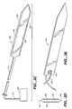
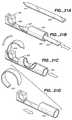
- FIG. 3Ashows one embodiment of a tissue locating element according to the present invention.
- FIG. 3Cshows another embodiment of a tissue locating element according to the present invention that is connected to an external energy source.
- FIG. 3Eis yet another embodiment of a tissue locating element according to the present invention connected to a flexible wire or suture.
- FIGS. 4A-4Cshow various views of a deployment tube and attached orientation element according to the present invention.
- FIGS. 5A-5Cshow various views of a tissue cutting element of the present invention disposed in a cannula for making an initial incision into tissue prior to deployment of the tissue locator element, complete with optional syringe and hub.
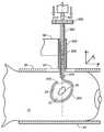
- FIG. 6shows breast tissue containing a lesion and surrounding tissue volume placed between two compression paddles.
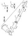
- FIG. 8shows the breast tissue and lesion of FIG. 6 with the blade removed and a trocar advanced into the tissue through the cannula to open up a pathway for accessing the lesion.
- FIG. 10shows the breast tissue and lesion of FIG. 6 with a locator element being advanced distally into the tissue by a pusher.
- FIG. 11shows the apparatus of FIG. 10 with the locator element advancing along a border of the tissue volume containing the lesion.
- FIG. 15is a top view of the apparatus of FIG. 14 with the second locator element fully deployed.
- FIG. 16is a perspective view of the apparatus of FIG. 14 with the second locator element fully deployed, demonstrating a polar deployment configuration.
- FIGS. 18A-18Bshow a perspective and top view, respectively, of a locator element of the present invention deployed in a tangential configuration.
- FIGS. 19A-19Bshow a perspective and top view, respectively, of two locator elements of the present invention deployed in a tangential configuration.
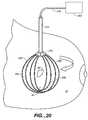
- FIG. 20shows two locator elements of the present invention connected to a source of energy.
- FIG. 22shows another embodiment of a cold-forming die according to the present invention.
- FIG. 23shows yet another embodiment of an adjustable cold-forming die of the present invention having reverse and positive die cavity curves.
- the invention described hereinis appropriate for a wide range of applications for marking a specific volume of tissue for excision or other purposes.
- the description belowis largely in the context of marking a nonpalpable lesion in breast tissue and its subsequent excision, the invention is not so limited.
- the invention described hereincan be used to mark tissue in a variety of locations in the body, such as the liver, the lungs, muscle tissue, or other tissue or organs where the advantages of the invention can be utilized. It may also be used to mark a foreign object in tissue or body cavities as well, such as a bullet or the like. Accordingly, the invention and method for its use as described and claimed below is not limited to the marking and removal of lesions from breast tissue.
- FIGS. 1A and 1Bdepict the current state-of-the-art tissue location methodology and equipment for nonpalpable breast lesions.
- FIG. 1Adepicts a cross-section of breast tissue 10 having the lesion 20 to be marked for later removal disposed between two compression paddles 30 (shown in cross-section).
- a window 50lies in the upper paddle 30 for accessing the lesion, which is surrounded by tissue volume 22 .
- a localization wire 40is shown placed in the lesion.
- the wire 40 depicted hereinis “J”-shaped, and it may have a barb or hook on its distal tip to assist in anchoring the wire 40 in the breast tissue 10 .
- breast tissue 10contains a typically nonpalpable lesion 20 or suspect tissue which is targeted for removal.
- Lesion 20may contain precancerous or cancerous cells or it may contain one or more microcalcifications, which are often precursors to metastatic cell growth. Microcalcifications typically appear in clusters.
- a radiologistperforms this procedure under local anesthesia, typically under x-ray guidance.
- a computermaps the breast tissue by generating a set of coordinates corresponding to the targeted lesion 20 and a portion of the tissue 10 surrounding the lesion.
- coordinatesare generated in three dimensions (x, y and z).
- the z coordinatetypically denotes to the depth of the lesion from the skin in a direction perpendicular to the surfaces of paddles 30 , while the x and y coordinates define a horizontal plane parallel to the plates 30 .
- This mapping procedurepinpoints the location of the lesion 20 as defined by the radiologist.
- the paddlesare adjusted so that lesion 20 is centered in the x-y plane below window 50 along a vertical (or z) axis.
- a small needleis next inserted into the tissue through window 50 in the upper compression plate 30 and moved towards the suspect tissue.
- This needle(not shown) acts as a deployment tube for localization wire 40 .
- a follow-up x-rayis taken of the lesion with wire 40 in place, and the radiologist will mark the x-ray image to indicate the location of lesion 20 .
- the radiologistnext decompresses the tissue and transfers the patient to surgery for removal of lesion 20 . It should be clear from this discussion that it is difficult at best to accurately determine the proper depth (along the z-axis) to which the surgeon should cut to safely and satisfactorily excise the lesion.
- Bracketingor “goalposting”
- goalpostingThe technique shown in FIG. 1B, called “bracketing” or “goalposting”, is often used in a second localization attempt when the radiologist was unsuccessful in marking the lesion in a prior attempt.
- these techniquesrequire post-excision re-imaging (and often re-excision and re-imaging) to ensure that the entire lesion is removed before the wound can be closed and the patient can be sent home.
- FIG. 2shows one embodiment of a tissue localization system 100 that overcomes the deficiencies of current systems and methods.
- System 100typically comprises the following subsystems or components: a tissue locator element 200 , locator element deployment tube 300 , a driver tube 400 , locator element orientation element or clock wheel 500 , tissue cutting element or blade 600 , trocar 420 , and pusher assembly 700 .
- blade 600which is slideably disposed in a lumen of driver tube or cannula 400 , is deployed through a distal end of cannula 400 into the breast tissue to the vicinity of the volume of tissue containing the lesion to be removed.
- Blade or cutting element 600may contain one or more tubular portions along its length, each having a lumen through which lubricant or an anesthetic may be administered as is discussed later.
- a proximal end of blade 600may be disposed in a lumen of tubular pusher element 730 , which is part of pusher assembly 700 .
- pusher assembly 700may also include a clamping ferrule or similar element 710 having a lumen for slideably receiving a proximal portion of blade 600 and, more importantly, locator element 200 .
- a thumbscrew or similar securing member 720is provided to fix a proximal section of blade 600 or locator element within the pusher assembly ferrule 710 .
- Pusher assembly 700may also be affixed to the aforementioned platforms or drivers in a variety of configurations; the arrangement described herein is merely exemplary.
- Locator element 200is preferably radiopaque, through the distal end of the tube 300 lumen to penetrate tissue and occupy the tissue volume boundary.
- Locator element 200is preferably designed to take on an arcuate or curvilinear shape when extended through the tube 300 distal end, such that as it penetrates tissue it follows a planar and preferably arcuate or curvilinear path to create a physical border around the majority of the perimeter of the targeted tissue volume, preferably without penetrating it.
- the locator element 200is designed to remain fixedly yet removably in place once deployed in tissue 10 as will be described later in greater detail.
- Delivery tube 300 , driver tube 400 , and any other component of system 100may then be removed, leaving only the locator element fixedly in place in the targeted tissue.
- the locator elementis long enough so that a reduced profile proximal end (or alternatively an attached suture or the like) extends proximally through the surface of the skin.
- the patientmay then either delay the excision procedure as desired or as dictated by the surgeon's schedule, or she may be transferred to surgery for excision of the marked volume.
- the surgeoncuts along the wire or the proximal portion of the locator element 200 , following it to the vicinity of the tissue volume.
- the surgeonexcises the tissue volume without invading the volume interior by cutting around the surface of the locator element opposite the locator element surface directly adjacent the tissue volume.
- the surgeonmay also access the locator element 200 by any number of approaches not necessarily along the proximal portion of element 200 , such as circumareolarly or via some other more direct or cosmetically acceptable approach as she sees fit.
- one or more additional locator elementsmay be deployed through delivery tube 300 into the tissue at an angle with respect to and about a longitudinal axis of the first locator element. This may be accomplished by the use of a clock wheel or orientation element 500 which may be rotated to orient the locator element or elements to a predetermined angle. Once oriented, the additional locator element or elements are deployed into the tissue in the same manner as the first locator element. These additional elements further define the same tissue volume along a different but similar arcuate path.
- each deployed locator element with respect to each othermay be arranged (e.g., at forty-five or ninety degrees) so that the spatial orientation and location of the tissue volume border occupied by the locator elements can be determined under x-ray or other visualization technique with greater accuracy.
- the remaining components of system 100may be removed and the tissue volume may be excised.
- FIGS. 3A-3Ddepict various embodiments of the locator element 200 .
- a particularly useful variation of element 200is shown in perspective as having a straight and flat configuration as it assumes when disposed in the confines of a deployment tube 300 lumen.
- proximal portion 210 and distal portion 220each have a similarly square or rectangular cross-sectional profile, but other profiles such as circular, elliptical, and irregular are also contemplated.
- the cross-sectional profile of proximal section 210need not be the same as the cross-sectional profile of distal portion 220 .
- FIG. 3Ashows only a width difference between proximal portion 210 and distal portion 220 , these portions may also differ in thickness as well.
- proximal portion 210The smaller cross-sectional area of proximal portion 210 compared to the distal portion 220 (as well as any possible differences in material properties when these portions are made from dissimilar materials) reduces the flexural modulus of proximal portion 210 relative to distal portion 220 . This affords greater flexibility or bendability to the device so to reduce the risk of locator element breakage, injury to others, and tissue trauma when proximal portion extends from the surface of the skin after locator element deployment but before excision.
- proximal portion 210is flexible enough to be freely and safely manipulated; for instance, proximal portion 210 can be taped or affixed to the patient's skin after deployment.
- Distal portion 220 of locator element 200is shown in FIGS. 3A and 3B as having a rectangular cross section and a distal end 230 that forms a blade or cutting surface. Alternatively or in addition, one or both of leading edge 250 or trailing edge 260 may form a blade or cutting surface.
- the particular shape of the distal end 230 and the cutting surface or surfacesare determined by the particular tissue in which the locator element 200 is designed to be placed and other clinical and practical parameters.
- the configuration of FIG. 3Ais but one of many possible to provide the most efficient advancing surface for moving through tissue.
- Energy source 265may provide other electrical energy forms to locator element 200 , or it may also or instead be a source of mechanical, thermal, acoustic or other type of energy as may be desired.
- distal portion 220 of locator elementmay incorporate a leading edge 250 , a trailing edge 260 , or both, as shown in FIG. 3 C.
- These portions 250 and 260preferably but not necessarily will have a sharpened profile so to provide a cutting surface for displacing tissue and providing a focus for the high frequency energy.
- FIG. 3Dcross-section of a distal portion 220 of locator element 200 that may be used with RF energy.
- an insulative coating or layer 280covers the two opposing surfaces of the locator element 220 adjacent leading edge 250 and trailing edge 260 .
- Such insulation 280serves to electrically isolate the surfaces covered by the insulation and further focuses the RF energy on the leading and trailing edges.
- Insulation 280may comprise a ceramic or metallic oxide (such as alumina, tantalum oxide, titanium oxide, etc.), a biocompatible polymer or any other suitable biocompatible electrically insulating material.
- Insulation 280may be in the form of a coating that can be applied by well-known deposition methods such as physical vapor deposition (including sputtering, evaporation, ion plating, ion beam-assisted deposition, ion implantation, etc.), diffusion (e.g., cementation), electrophoresis, anodizing, plating, chemical vapor deposition, pulsed laser deposition, painting, dipping, electroplating, laser surface processing, thermal spraying, etc. Insulation 280 may also be formed in situ via surface oxidation, etc. Insulation 280 may completely cover the opposing surfaces of distal portion 220 as shown in FIG.
- deposition methodssuch as physical vapor deposition (including sputtering, evaporation, ion plating, ion beam-assisted deposition, ion implantation, etc.), diffusion (e.g., cementation), electrophoresis, anodizing, plating, chemical vapor deposition, pulsed laser deposition, painting,
- insulative coating 280has a low coefficient of friction to ease the movement of locator element through tissue. It is even contemplated that the locator element be coated with a noninsulative but low-friction coating, whether the device is used with RF or other energy or not, simply to achieve this goal.
- FIG. 3Eshows another variation of locating element 200 in which a flexible wire, cable, suture or the like 290 is attached to locating element via eyelet 292 .
- the overall length of locating element 200can be considerably shorter than other variations, as the cable 290 may be viewed as taking the place of locator element proximal section 210 .
- a suture 290is even more suitable than the proximal portion shown in FIG. 3A for presenting a flexible, safe, and effective “lead” that may extend out through the breast surface after the locator element has been placed in the tissue.
- Locator element 200is designed to assume a generally arcuate or curvilinear shape when unconstrained or when deployed in tissue.
- locator element 200comprise a material having a shape memory, such as spring steel, stainless steel, nickel-titanium alloy such as nitinol, a shape memory polymer, or other such materials.
- locator element 200be nickel-titanium, although less desirable alloys (from a toxicity standpoint) that exhibit shape memory characteristics, such as copper-zinc-aluminum, copper-aluminum-nickel, copper-zinc-silicon, copper-zinc-lead, gold-cadmium, and nickel-cadmium, are contemplated as well.
- Locator elementmay be mechanically straightened to assume a first generally linear or flat configuration as it is inserted into deployment or delivery tube 300 or equivalent constraining member. As the distal end of the locator element 200 is deployed beyond the distal end of delivery tube 300 into the tissue of interest by pusher assembly 700 , locator element 200 naturally assumes a second, substantially arcuate or curvilinear profile discussed above as it penetrates tissue and defines a tissue border along a path. The tissue border defines a tissue volume containing the targeted lesion that is to be excised. Preferably, locator element 200 does not penetrate the tissue volume as it is deployed.
- This shape transformation described aboveis preferably entirely temperature-independent; that is, it may take place at a single temperature simply upon removing the physical or mechanical constraint of tube 300 or the like as it deploys into tissue or a cavity.
- materials exhibiting temperature-dependent transformation propertiesfor instance, those materials which can be engineered to transform from a flat, planar shape into an arcuate or curvilinear shape upon reaching a temperature threshold (such as body temperature), may be used for locator element as well.
- Locator elementmay also assume more complex shapes having more than a single curve or even curves that change direction.
- locator element 200be at least partially radiopaque so that it may be readily viewed under x-ray energy. This aids the radiologist in placing locator element 200 in the desired tissue position as well as allowing for verification of its location and orientation.
- Locator elementmay be radiopaque by virtue of its inherent material properties; i.e., nitinol exhibits both a shape memory effect and some radiopacity as well, making it a suitable material for use in the locator element.
- the radiopacity of locator element 200may be enhanced by adding a variety of components comprising materials exhibiting greater radiopacity, such as bands or elements made from platinum, palladium, tungsten, gold, silver, etc., that may be bonded or otherwise affixed to locator element 200 in predetermined locations (such as, e.g., along the leading edge 250 and trailing edge 260 or on the distal end of locator element 200 ). If locator element distal section 200 is insulated, such insulation may be radiopaque as well. For instance, polytetrafluoroethylene doped with barium sulfate or some other appropriate radiopaque material is suitable for this purpose.
- the distal portion 220 of locator element 200preferably comprises a ribbon having a rectangular cross section. Such a shape provides a surface against which the surgeon may cut when excising the tissue volume contained by the locator element.
- the orientation of the locator elementcan be readily determined under x-ray visualization depending upon which surface (i.e. a leading or trailing edge as opposed to a wider surface) is presented to the viewer. Even if the deployed locator element 200 occupies multiple planes in the tissue with respect to the x-ray or ultrasound source, such information should be readily visible due to the asymmetric shape of ribbon locator element 200 .
- distal portion 220be a ribbon as described above, it is not so limited.
- the distal portion 220may have a circular, elliptical, oval, or irregular cross-sectional shape.
- Various rectangular cross-sectional shapesranging from square to those having higher cross-sectional aspect ratios (i.e., a ribbon) are contemplated as well.
- distal portion 220 of locator element 200may be between about 1.0 mm and 7.0 mm wide and between about 0.2 mm and 1.0 mm thick; we prefer it to be between about 2.0 mm and 5.0 mm wide and about 0.5 mm and 0.8 mm thick.
- Other cross-sectional shapespreferably are on the order of the same dimensions as those recited above.
- a shoulder portion 240may transition from the ribbon portion having a rectangular cross section to a proximal portion 210 having a generally square or rectangular cross section with a thickness preferably the same as that of distal portion 220 and a width on the order of approximately 30 percent to approximately 80 percent of the width of distal portion 220 .
- the particular ratio of the widths of proximal portion 210 to distal portion 220will depend on the design constraints associated with the particular application for which system 100 is chosen.
- the cross-sectional shape of proximal portion 210does not have to be the same as that of distal portion 220 .
- locator element 200and its operation in conjunction with the other components of system 100 are discussed below in greater detail.
- FIGS. 4A and 4Boval deployment or delivery tube or delivery 300 is shown connected to orientation element or clock wheel 500 .
- Deployment tube 300is the primary device through which locator element 200 is delivered to the targeted tissue volume perimeter.
- the particular design elements of tubeare not critical to the operation of the invention; as long as it effectively aids in delivering locator element 200 to the proper location, deviations from the features described herein and shown in the figures are possible.
- Delivery tube 300preferably has a lumen 310 that has a generally oval cross-sectional shape to accommodate the rectangular cross-sectional shape of locator element 200 and to present a lower profile when penetrating tissue. This ensures proper deployment of locator element 200 in the desired position and angular orientation.
- cannula lumen 310may assume a variety of other cross sectional shapes, including circular, rectangular, irregular, etc. In any event, we particularly prefer that cannula lumen 310 have cross-sectional dimensions sized so that the locator element 200 may freely axially or slideably move therein; in addition, free or limited rotational movement of locator element 200 therein is also contemplated.
- tube 300be a stainless steel hypotube or the like, although it may comprise a polymer, nickel-titanium, a composite material, or other metals such as platinum, tungsten, cobalt, titanium and their alloys.
- a proximal section 310 of tube 300terminates at interface 330 with an orientation element or clock wheel 500 as shown in FIGS. 4A and 4B.
- Interface 330can be a simple recessed interference fit or other type of joint between the proximal end 310 of tube 300 and wheel 500 .
- Interface 330need not be permanent; it may be designed so that the proximal section 310 can be removably inserted into orientation element 500 , locked in place, and removed so that another tube 300 (perhaps with a different cross-sectional shape) can be fit therein.
- orientation element 500 and delivery tube 300may be integrally formed as a single unit so that interface 330 is simply a transition between the two.
- flange 510has a straight or flat edge 530 to indicate to the radiologist the particular angular orientation of tube 300 selected.
- system 100may be configured so that when the flat section 530 is aligned with stereotactic guide unit 80 (see FIGS. 7 - 9 ), the radiologist knows that the major axis of oval deployment tube 300 , and in turn the major axis along the width of locator element 200 , is aligned with the particular axis indicated by guide unit 80 .
- flange 510may have an additional flat surface parallel to surface 530 on the opposite side of flange 510 .
- wheel 500may contain notches, raised sections, alphanumeric markings, electronic indicators (audible, visual, etc.), or combinations of these and other features to indicate the angular orientation of element 500 with respect to the tissue coordinate system. Any device that indicates to the user the spatial orientation of tube 300 and in turn locator element 200 is within the scope of this present invention.
- Orientation element 500may be metallic or polymeric as dictated by design and functional considerations.
- trocar or blade 600is shown partially slideably disposed in a lumen of driver tube 400 .
- blade 600is designed for deployment through driver tube 400 to initially penetrate tissue and create an access pathway through which delivery tube 300 and eventually one or more locator elements 200 may be deployed.
- Driver tube or cannula 400is preferably oval in cross-section to present a low profile configuration (as shown in FIG. 2 ), although it may have a more round cross-section (as shown in FIGS. 5A and 5C) or a cross-section that conforms to the cross-sectional profile of blade 600 , especially the blade distal region 620 as discussed below.
- any cross-sectional shape for cannula 400 suitable for deploying blade 600 , deployment tube 300 , and locator element 200is within the scope of the invention.
- driver tube 400be sized so that the deployment tube 300 may freely axially or slideably move therein; in addition, free or limited rotational movement of delivery tube 300 therein is also contemplated.
- cannula 400be a stainless steel hypotube or the like, although it may comprise a polymer, nickel-titanium, a composite material, or other metals such as platinum, tungsten, cobalt, titanium and their alloys.
- Blade edges 650are seen disposed along a single axis and joining at a single point near the distal end of blade 600 .
- Blade edges 650may take on a number of different configurations. They may be serrated, for example, and they may be capable of using electrical, acoustic, mechanical, or thermal energy as described herein. Although the particular tip features and configuration of blade edges 650 may vary considerably and be within the scope of the invention, we have found the configuration of FIGS. 5A-5C to be particularly useful for cutting through breast tissue.
- FIGS. 5A-5Cshow only two tubular members 660 , the invention is not so limited. Any number of tubular members may be used with this invention, from one to six or more, depending upon the needs of the patient and the objective of the procedure in which blade 600 is being used.
- Blade and tubular membermay be metallic, polymeric, a composite material, or a combination of metals, polymers, and their alloys as described herein. Particularly useful is stainless steel.
- the various components of this variation of trocar 600may be integrally formed as a single element, or they may be assembled via any number of a suitable joining techniques, such as welding, brazing, soldering, adhesives, or the like.
- blade edges 650be hardened stainless steel so to provide a keener cutting surface that does not dull with use.
- a valve and seal system as is well-known in the artmay accompany hub 690 to facilitate selective administration of the desired agent.
- FIGS. 6-17show, in detailed fashion, a method for using system 100 to mark a volume of tissue for eventual removal or excision from the breast, preferably without penetrating or otherwise violating the interior of the tissue volume.
- a particularly useful technique in which one or more locator elements are deployed in a “polar” fashionis described below.
- this methodis described in the context of removing a nonpalpable lesion from the breast, it may be followed for marking and excising any tissue mass or foreign object from the body.
- a methodfor defining the border of a tissue volume to be excised from a patient. This is accomplished by deploying at least one locating element into breast tissue so that it follows a continuous path around the selected tissue volume, thereby containing the target tissue region. Later excision of the so-marked tissue volume by a surgeon is also described.
- the patientis typically first prepared for the marking procedure by placing the breast tissue 10 between two compression paddles 30 on a platform such as a Fisher Table.
- the tissue volume 22 containing the suspect lesion 20is next mapped under x-ray guidance and a three-dimensional coordinate system or grid is assigned to the tissue of interest.
- a three-dimensional coordinate system or gridis assigned to the tissue of interest.
- the entire breast tissue 10 between plates 30is mapped on a three-dimensional coordinate system.
- “x” and “y” coordinates in FIG. 6are associated with a tissue location along axes in a horizontal plane parallel to paddles 30 .
- the “z” coordinatedescribes a tissue location in a vertical or depth plane perpendicular to each of the x and y axes.
- the radiologistmay manually advance blade 600 into tissue 10 , preferably with the assistance of x-ray, ultrasound, magnetic resonance, or other method.
- Such a techniquemay be preferable, especially under difficult or delicate conditions where caution and control are at a premium.
- blade 600will penetrate tissue 10 so that its distal end 640 just reaches the vicinity of the surface or border of tissue volume 22 .
- blade distal end 640will reach the border of tissue volume 22 along the z-axis as described above, while other deployment schemes may dictate deployment at other locations along or near the border of tissue volume 22 .
- blade 600is equipped with one or more tubular members 660 as previously described, lubricating agents, anesthetics such as lidocaine, or any number of other appropriate pharmaceutical agents may be administered through the tubular member lumen 660 so that they are deployed into the tissue through tube distal end 680 .
- lubricating agentssuch as lidocaine
- anestheticssuch as lidocaine
- any number of other appropriate pharmaceutical agentsmay be administered through the tubular member lumen 660 so that they are deployed into the tissue through tube distal end 680 .
- agentsare administered simultaneously as the blade 600 is advanced into tissue 10 ; however, they may be administered before or after the pathway is created.
- one or more sensors, fiber optics, electrocautery electrodes (to control bleeding during cutting), or other devicesmay be deployed through lumen 660 .
- FIG. 8shows system 100 after blade has been proximally withdrawn from tissue 10 and cannula 400 and a conventional trocar 420 has been deployed into the lumen of driver tube 400 until its distal end 430 extends distally of the distal end of cannula 400 .
- Trocar 420 and cannula 400may then be advanced as a unit, or with the trocar leading in sequential deployment, into the tissue 10 through the pathway created by blade 600 to further define and enlarge it.
- trocar 420is advanced just to the edge or border of tissue volume 22 as previously described for deployment of blade 600 while the cannula 400 does not extend into tissue 10 .
- a blade, trocar, and cannulaare used to create the access port or pathway in tissue 10 to reach tissue volume 22 may be performed in any sequence or in any of a number of ways not described herein but are as known to those of skill in the art. It is not critical to the invention for the pathway or port to be created as described above. The steps described above are merely exemplary of a method we have found to be useful; as long as a port is created in which the invention as described herein may be practiced, any method is acceptable.
- FIG. 9shows cannula 400 after trocar 420 has been withdrawn and oval deployment tube 300 is inserted through the driver tube 400 lumen and advanced distally to the vicinity of the border of tissue volume 22 .
- tube 300is advanced to a position just proximal to tissue volume 22 at the distal end of the tissue pathway as shown in FIG. 9 .
- Deployment tube 300is shown in FIG. 9 connected to an orientation element 500 for indicating the alignment of locator element 200 as described above.
- FIG. 10depicts the next step.
- Distal portion 220 of locating element 200has a ribbon or similar cross-sectional profile in which its width is larger than its thickness.
- the proximal portion 210 of locator element 200is disposed in pusher tube 730 , which in turn are disposed in deployment tube 300 .
- This assemblyis then placed in the lumen of cannula 400 .
- FIG. 10 view of locator elementis looking along its width, so that only the uniform thickness of the locator element 200 as one moves from proximal portion 210 to distal portion 220 can be seen. Therefore, only the edge of shoulder 240 is seen. However, the distal end of pusher tube 730 is shown abutting shoulder 240 so that as the proximal portion 210 of locator element 200 is distally advanced into the tissue, the distal portion 220 of locator element 200 exits the distal end of deployment tube 300 to enter the tissue 10 in the vicinity of tissue volume 22 .
- proximal portion 210 of locator element 200has a longitudinal axis that is substantially aligned or overlapping with the z-axis or central axis of the tissue volume 22 . See the single dashed line bisecting lesion 20 in FIG. 10, which represents the position these axes take.
- FIGS. 11-13show successive views of locator element 200 as it continues to advance along a path to define a tissue border of tissue volume 22 (now with stereotactic guide unit 80 removed for clarity).
- the radiologistcauses the pusher assembly 700 to advance distally, the distal end of pusher tube 730 continues to engage shoulder portion 240 to likewise distally advance the locator element 200 .
- Locator element 200may also take on a number of other shapes once deployed as previously discussed. The particular shape of the locator element is dictated by the shape of the tissue volume 22 and the particular tissue being excised.
- locator element 200deploys along the first path in the tissue volume border 24 such that the distalmost portion of the tissue volume is encompassed by the path formed by the locator element 200 .
- distal portion 220 of element 200extend to or even around the distalmost portion of tissue volume 22 (as measured in a downward direction along the z-axis) such that the element 200 bounds the tissue volume 22 containing the targeted lesion 20 along a continuous path.
- This pathmay be viewed as forming a physical border around the majority of the perimeter of the tissue volume 22 .
- distal portion 220 of locating element 200continues well past the most distal portion of tissue volume 22 and forms a loop that substantially encompasses the border 24 along this path.
- proximal portion 210 of the locator element 200when the locator element 200 is deployed into position as described above, manipulation of a proximal portion 210 of the locator element 200 will result in an equivalent or proportional manipulation of the tissue volume 22 enclosed by the element 200 . For instance, if a proximal portion of element 200 is moved along the z axis, the targeted lesion 20 and enclosing tissue volume 22 will move an equal or proportional distance along the z axis. Likewise, pivoting or otherwise manipulating proximal portion 210 will result in a concomitant pivoting or other movement of the enclosed tissue volume 22 . If the proximal portion 210 is replaced by a flexible cable, wire or suture as discussed above, manipulation of the wire results in a likewise and proportional manipulation of tissue volume 22 .
- a second important advantage of this feature of system 100is that the surgeon may excise the tissue mass 22 by cutting along the surface of the locator element opposite the tissue volume and be confident that the entire volume 22 will be excised because the distalmost portion of the volume is encompassed by the locator element 200 .
- locator element 200may wish to partially or completely remove the element 200 from the body. For instance, if the locator element 200 is misdeployed or if there is a malfunction of some component of system 100 , it may be desirable to reposition or even completely remove locator element 200 from the body.
- the radiologistsimply pulls the proximal portion 210 or wire 290 in the proximal direction so that the locator element 200 retreats proximally into deployment tube 300 , and straightens into its predeployment shape. She may exert opposite force in the distal direction on the pusher assembly 700 to provide leverage. Of course, the thumbscrew 720 in ferrule 710 should be loose to allow relative movement between the locator element 200 and pusher assembly 700 .
- the radiologistmay tighten thumbscrew 720 to fix the locator element proximal portion 210 in the ferrule 710 and continue to pull either the locator element or the affixed pusher tube proximally to further withdraw the locator element as she sees fit.
- the radiologistmay decide to refrain from deploying one or more additional locator elements and present the patient to the surgeon for removal of the tissue volume 22 .
- Thisis perfectly acceptable and is within the scope of the invention.
- the lesionmay be well-defined and conditions are such that excision of tissue volume 22 along a single locator element may be confidently accomplished.
- At least one additional locator elementmay be deployed in the tissue. This is shown in simplified FIGS. 14-16 and discussed below.
- orientation element 500is rotated ninety degrees so that the major axis of tube 300 and, when inserted into tube 300 lumen, the accompanying width of locator element 200 ′ is oriented ninety degrees with respect to the width of deployed locator element 200 , or so that the locator element 200 ′ will deploy in a second path that is generally parallel to the y-axis.
- second locator element 200 ′is inserted and advanced distally into the lumen of deployment tube 300 as previously described with respect to the first locator element.
- the second locator elementis advanced through the distal end of the tube 300 and penetrates tissue 10 so that locator element 200 ′ further defines the tissue border 24 along a second path without penetrating tissue volume 22 .
- a second planeis defined that is preferably non-parallel to the plane defined by the first locator element 200 .
- the second planeis angularly displaced approximately ninety degrees with respect to the first plane in accordance with the amount of rotation deployment tube 300 . This is shown along a “polar” z-axis in the view of FIG. 15, looking down at the tissue volume 22 in the z direction, where the angular displacement a between the first and second locator elements 200 and 200 ′ can be readily seen.
- the second locator element 200 ′When two locator elements are used to mark the tissue volume 22 for excision, we prefer to deploy the second locator element 200 ′ so that it is angularly displaced in the tissue approximately ninety degrees with respect to the first locator element 200 as discussed above. Such a displacement is preferred, especially when each element is radiopaque and similarly shaped (i.e., a ribbon or other asymmetric cross-section), because of the ease with which the radiologist can view an x-ray image of the deployed locator elements and determine their orientation with respect to the grid assigned to the tissue.
- first and second locator element 200 ′may be angularly displaced approximately forty-five degrees with respect to one another. This may be preferred, for instance, if a third locator element is used, or if the particular lesion 20 , patient condition, practitioner preference, or combination of these or other factors so dictate.
- the second locator element 200 ′be displaced at any angle with respect to the first locator element around the common polar or z-axis.
- the orientation element 500may be infinitely rotatably variable; alternatively or additionally, it may rotatable in fixed angular increments.
- tissue volume 22 containing the suspect lesion 20is bounded by first locator element 200 and second locator element 200 ′ as schematically shown in FIGS. 15 and 16.
- Tissue volume 22may be removed by any number of techniques as discussed below.
- a third locator element 200 ′′(not shown) may also be deployed as previously described so that at least a portion of the third locator element 200 ′′ further defines the tissue border along a third path.
- This third pathwill preferably define a third plane that is non-parallel to the first and second planes.
- each locator element(or alternatively flexible wire or suture 290 ) extends through the skin surface.
- the sutureshould extend through the tissue 10 and the skin surface so that it may be manipulated.
- tissue marking and removal processOne advantage of this portion of the tissue marking and removal process is that if the other components of system 100 are removed from the vicinity of tissue 10 , leaving only one or more locator elements and perhaps an attached suture extending through the skin surface, the tissue volume 22 does not have to immediately be excised as is the case with other tissue marking devices.
- the proximal portion 210 of locator element or the suture 290is flexible enough that it may be taped or otherwise affixed to the patient's skin so that the patient may wait up to several days or more, with the chance to go home, before the volume 22 is removed by the surgeon. In this manner, the patient can be scheduled for excision at a convenient time within minutes or up to several days from the time of deployment.
- the patient and surgeonare ready to excise the tissue volume 22 , the patient is put under anesthesia and the surgeon accesses the tissue volume using conventional surgical tools such as scalpel 90 . She will cut around the outside surface of the locator elements to separate the tissue volume 22 from tissue 10 and then remove the tissue volume from the body. This is illustrated in FIG. 17 .
- the surgeonwill first reach the tissue volume through any number of approaches. Some situations will dictate that the surgeon access the tissue volume 22 by cutting into the tissue 10 along the proximal portion 210 of the one or more locator elements 200 or along the flexible wire or suture 290 attached to the locator element. Such an approach may be favored if the tissue volume 22 is near the surface of the skin and cutting along this path is the shortest and most clinically acceptable path. If the locator element deployment tube 300 is still in the tissue 10 , the surgeon may readily access the locator element along its surface, which is easy to locate and follow with a scalpel to the locator element.
- the surgeonmay wish to approach the locator element along a path different than the proximal portion of locator element or suture. Under x-ray or other type of guidance, for instance, the surgeon may penetrate through the tissue 10 at a second site such as that shown in FIG. 17 as path 92 if, for clinical, cosmetic, or other reasons it is preferable to do so.
- a circumareolar approach 94which minimizes the appearance of any scar, may be preferred. It should be noted that when an alternative surgical path to reach and remove the locator element and the enclosed tissue, even the proximal portion of locator element may be removed through this alternative path as formed by the surgeon. This allows the relatively small incision diameter through which the locator element was originally deployed to remain basically undisturbed.
- the fact that the surgeon may access the tissue volume 22 along a path different than the initial deployment path for system 100is because the tissue volume 22 is now “palpable” in the sense that its border or perimeter is defined and occupied by one or more locator elements that can be palpated.
- the tissue volume 22is in a sense encapsulated by the locator elements.
- tissue 10Once the surgeon has cut through tissue 10 to reach the locator elements, she will next begin cutting through tissue 10 substantially along a surface of the locator element 200 which is opposite a surface of each locator element 200 disposed immediately adjacent the tissue volume 22 . In other words, the surgeon will find the outside of the “cage” formed by the one or more locator elements and begin cutting along its surface to separate tissue immediately adjacent the outer surface of the “cage” from the tissue enclosed but not penetrated by the one or more locator elements.
- the surgeoncuts along the outer surface of the locator elements, she is able to discern the volume by visual and tactile cues, aided by her experience, and will cut around tissue volume 22 without penetrating it. Eventually, she will cut tissue volume 22 free from the surrounding tissue 10 so that it may be lifted with the locator elements enclosing the volume out of the tissue 10 .
- FIGS. 18-19show a deployment of one or more locator elements 200 via an alternative tangential deployment technique.
- the initial point of deployment of the distal end of the locator element 200 as it extends out of the deployment tube 300 lumenis substantially along a line that is tangent to the tissue volume 22 to be removed.
- a longitudinal axis 95 of a proximal portion of the locator element 200is now substantially aligned with a tangential axis 96 of tissue volume 22 instead of a tissue volume central or polar (z) axis 98 .
- Thisis shown for a single locator element in FIGS. 18A (perspective view) and 18 B (planar view looking along the z-direction).
- FIGS. 19A and 19Bdepict two locator elements 200 and 200 ′ defining the border or perimeter of tissue volume 22 after having been tangentially deployed along tangential axes 102 and 104 , respectively, as described above.
- each locator elementgenerally deploys into tissue along a single central or polar axis of the tissue volume, thus requiring only a single tissue passageway as previously described.
- Clamp 276should be electrically conductive so to transmit the RF energy to the locator elements.
- An optional ground plate or similar return electrode(not shown) may be disposed on the patient's skin on tissue mass 10 or any other suitable part of the patient's body. Alternatively, the system may be configured to operate in bipolar mode with no need for a return electrode.
- Energy source 265may also be used to energize the locator element to provide electrocauterizing energy to the tissue as it is being excised so to minimize bleeding, etc.
- One particularly useful configurationis where at least one edge 250 or 260 of the locator element forms a cutting surface or blade to cut through tissue when the locator element is rotated as described above.
- This type of locator elementmay also be complemented by RF or other energy sources to assist the locator element cutting surface in cutting or separating tissue 10 .
- FIGS. 21-23an alternative locator element 205 is shown being formed in situ by an alternative deployment tube 305 .
- the deployment tube 305 containing die 307is proximally withdrawn or rotated for the optional deployment of an additional locator element as discussed in detail above.
- locator element 205is a ribbon or similar form having a width larger than its thickness.
- die 307 and die cavity 309are appropriately shaped to impart the proper amount of plastic deformation for the dimensions of locator element 205 and the material used so to exceed the elastic limit of the locator element while avoiding overstressing it, which could cause edge or surface cracking that could interfere with the element's performance. More or less severe curves than that shown for die cavity 309 are within the scope of the invention.
- Other die cavity profilesmay include irregular and other various shapes, such as reverse curves, etc., so that a variety of desired final shapes of the formed locator element 205 may be realized.
- Die 307may be made of any appropriate material suitable for serving its intended purpose.
- the diecomprises a biocompatible tool steel such as a tungsten or low-alloy steel or other metal, alloy of such, or composite as may be appropriate.
- Locator element 205may comprise any suitable material as discussed above, including those materials that do not exhibit shape memory characteristics. Other than the typical materials requirements such as biocompatibility, radiopacity, etc., the material should at least also be selected to allow the locator element to exceed the elastic limit so to plastically deform into the permanent shape as it is passed through die 307 .
- FIG. 23depicts a variation of the embodiment of FIG. 22 in which die 317 is adjustable.
- lead screw 319 or a similar elementis rotatably disposed in a lumen of the upper portion 321 of the die that is slideably affixed to die lower portion 323 . Rotation of screw 319 in either direction moves upper portion 321 distally or proximally relative to lower portion.
- the distal end 325 of lower portion of the dieis curved so to impart a particular curvature to die cavity 327 , thereby imparting a corresponding curvature to locator element 205 as it passes through.
- Distal end 329 of die upper portionis appropriately shaped with a positive curve to impart a final shape to locator element 205 as discussed with respect to the FIG. 22 embodiment.
- the axial adjustability of the upper portion 321allows the distal ends of each portion of die 317 to form a variety of positive curve shapes that in turn will form locator element 205 rings having a variety of different diameters, ranging preferably from between about 0.5 cm to about 3.0 cm or more.
- Lead screw 319is but one of any number of mechanisms suitable for adjusting the axial position of die upper portion 321 relative to die lower portion 323 within the scope of the invention.
Landscapes
- Health & Medical Sciences (AREA)
- Surgery (AREA)
- Life Sciences & Earth Sciences (AREA)
- Heart & Thoracic Surgery (AREA)
- Molecular Biology (AREA)
- Oral & Maxillofacial Surgery (AREA)
- Engineering & Computer Science (AREA)
- Biomedical Technology (AREA)
- Nuclear Medicine, Radiotherapy & Molecular Imaging (AREA)
- Medical Informatics (AREA)
- Pathology (AREA)
- Animal Behavior & Ethology (AREA)
- General Health & Medical Sciences (AREA)
- Public Health (AREA)
- Veterinary Medicine (AREA)
- Surgical Instruments (AREA)
- Laser Surgery Devices (AREA)
- Prostheses (AREA)
- Investigating Or Analysing Biological Materials (AREA)
Abstract
Description
Claims (134)
Priority Applications (19)
| Application Number | Priority Date | Filing Date | Title |
|---|---|---|---|
| US09/507,361US6564806B1 (en) | 2000-02-18 | 2000-02-18 | Device for accurately marking tissue |
| US09/613,686US6405733B1 (en) | 2000-02-18 | 2000-07-11 | Device for accurately marking tissue |
| US09/699,254US6722371B1 (en) | 2000-02-18 | 2000-10-27 | Device for accurately marking tissue |
| AT01910815TATE490720T1 (en) | 2000-02-18 | 2001-02-16 | IMPROVED DEVICE FOR ACCURATE TISSUE MARKING |
| EP01910815AEP1259155B1 (en) | 2000-02-18 | 2001-02-16 | Improved device for accurately marking tissue |
| EP20100012131EP2298154B1 (en) | 2000-02-18 | 2001-02-16 | Improved device for accurately marking tissue |
| EP09004543.6AEP2077090B1 (en) | 2000-02-18 | 2001-02-16 | Improved device for accurately marking tissue |
| PCT/US2001/005013WO2001060235A2 (en) | 2000-02-18 | 2001-02-16 | Improved device for accurately marking tissue |
| ES01910815TES2356059T3 (en) | 2000-02-18 | 2001-02-16 | IMPROVED DEVICE FOR MARKING FABRICS WITH ACCURACY. |
| DE60143604TDE60143604D1 (en) | 2000-02-18 | 2001-02-16 | IMPROVED DEVICE FOR EXACTLY MARKING TISSUE |
| EP15164319.4AEP2932891A1 (en) | 2000-02-18 | 2001-02-16 | Improved device for accurately marking tissue |
| AU2001238382AAU2001238382A1 (en) | 2000-02-18 | 2001-02-16 | Improved device for accurately marking tissue |
| JP2001559336AJP5090600B2 (en) | 2000-02-18 | 2001-02-16 | Improved device for accurately marking tissues |
| US09/935,477US6752154B2 (en) | 2000-02-18 | 2001-08-22 | Device for accurately marking tissue |
| US10/798,776US7322360B2 (en) | 2000-02-18 | 2004-03-10 | Device for accurately marking tissue |
| JP2010286671AJP5576259B2 (en) | 2000-02-18 | 2010-12-22 | Improved device for accurately marking tissues |
| JP2013062555AJP5918165B2 (en) | 2000-02-18 | 2013-03-25 | Improved device for accurately marking tissues |
| JP2014153821AJP6294181B2 (en) | 2000-02-18 | 2014-07-29 | Improved device for accurately marking tissues |
| JP2016251695AJP2017074453A (en) | 2000-02-18 | 2016-12-26 | Improved device for accurately marking tissue |
Applications Claiming Priority (1)
| Application Number | Priority Date | Filing Date | Title |
|---|---|---|---|
| US09/507,361US6564806B1 (en) | 2000-02-18 | 2000-02-18 | Device for accurately marking tissue |
Related Child Applications (1)
| Application Number | Title | Priority Date | Filing Date |
|---|---|---|---|
| US09/613,686Continuation-In-PartUS6405733B1 (en) | 2000-02-18 | 2000-07-11 | Device for accurately marking tissue |
Publications (1)
| Publication Number | Publication Date |
|---|---|
| US6564806B1true US6564806B1 (en) | 2003-05-20 |
Family
ID=24018339
Family Applications (2)
| Application Number | Title | Priority Date | Filing Date |
|---|---|---|---|
| US09/507,361Expired - LifetimeUS6564806B1 (en) | 2000-02-18 | 2000-02-18 | Device for accurately marking tissue |
| US09/613,686Expired - LifetimeUS6405733B1 (en) | 2000-02-18 | 2000-07-11 | Device for accurately marking tissue |
Family Applications After (1)
| Application Number | Title | Priority Date | Filing Date |
|---|---|---|---|
| US09/613,686Expired - LifetimeUS6405733B1 (en) | 2000-02-18 | 2000-07-11 | Device for accurately marking tissue |
Country Status (6)
| Country | Link |
|---|---|
| US (2) | US6564806B1 (en) |
| EP (3) | EP2298154B1 (en) |
| JP (4) | JP5576259B2 (en) |
| AT (1) | ATE490720T1 (en) |
| DE (1) | DE60143604D1 (en) |
| ES (1) | ES2356059T3 (en) |
Cited By (95)
| Publication number | Priority date | Publication date | Assignee | Title |
|---|---|---|---|---|
| US20030109862A1 (en)* | 2001-11-02 | 2003-06-12 | Mani Prakash | High-strength microwave antenna assemblies and methods of use |
| US20030191487A1 (en)* | 2002-04-03 | 2003-10-09 | Robison Braden M. | Surgical cutting accessory with nickel titanium alloy cutting head |
| US20030195500A1 (en)* | 1999-06-17 | 2003-10-16 | Moorman Jack W. | Needle kit and method for microwave ablation, track coagulation, and biopsy |
| US20030195499A1 (en)* | 2002-04-16 | 2003-10-16 | Mani Prakash | Microwave antenna having a curved configuration |
| US20030236534A1 (en)* | 2002-04-17 | 2003-12-25 | Helmut Kayan | Tacking tool and tack |
| US20040122312A1 (en)* | 2002-11-18 | 2004-06-24 | Inrad, Inc. | Apparatus and method for implanting a preloaded localization wire |
| US20040168692A1 (en)* | 2000-02-18 | 2004-09-02 | Thomas Fogarty | Device for accurately marking tissue |
| US20050062666A1 (en)* | 2001-11-02 | 2005-03-24 | Vivant Medical, Inc. | High-strength microwave antenna assemblies |
| WO2005089065A2 (en) | 2004-03-23 | 2005-09-29 | Dune Medical Devices Ltd. | Clean margin assessment tool |
| US20060177852A1 (en)* | 2001-12-12 | 2006-08-10 | Do-Coop Technologies Ltd. | Solid-fluid composition |
| US20060259024A1 (en)* | 2005-05-10 | 2006-11-16 | Roman Turovskiy | Reinforced high strength microwave antenna |
| US20060264738A1 (en)* | 2003-07-24 | 2006-11-23 | Dune Medical Devices Ltd. | Method and apparatus for examining a substance, particularly tissue, to characterize its type |
| US20060271041A1 (en)* | 2005-05-12 | 2006-11-30 | Joseph Eder | Method for Tissue Cauterization |
| US20070021763A1 (en)* | 2004-11-22 | 2007-01-25 | Inrad, Inc. | Removable Localizing Wire |
| US20070032747A1 (en)* | 2005-08-04 | 2007-02-08 | Dune Medical Devices Ltd. | Tissue-characterization probe with effective sensor-to-tissue contact |
| US20070032739A1 (en)* | 2005-08-04 | 2007-02-08 | Dune Medical Devices Ltd. | Device for forming an effective sensor-to-tissue contact |
| US20070179397A1 (en)* | 2002-01-04 | 2007-08-02 | Dune Medical Devices Ltd. | Probes, systems, and methods for examining tissue according to the dielectric properties thereof |
| US20070197934A1 (en)* | 1998-09-03 | 2007-08-23 | Rubicor Medical, Inc. | Devices and methods for performing procedures on a breast |
| US20070255169A1 (en)* | 2001-11-19 | 2007-11-01 | Dune Medical Devices Ltd. | Clean margin assessment tool |
| US20070265613A1 (en)* | 2006-05-10 | 2007-11-15 | Edelstein Peter Seth | Method and apparatus for sealing tissue |
| US7311703B2 (en) | 2003-07-18 | 2007-12-25 | Vivant Medical, Inc. | Devices and methods for cooling microwave antennas |
| US20080021343A1 (en)* | 2002-01-04 | 2008-01-24 | Dune Medical Devices Ltd. | Probes, systems, and methods for examining tissue according to the dielectric properties thereof |
| US20080154090A1 (en)* | 2005-01-04 | 2008-06-26 | Dune Medical Devices Ltd. | Endoscopic System for In-Vivo Procedures |
| US20080195146A1 (en)* | 2002-03-11 | 2008-08-14 | Wardle John L | Surgical coils and methods of deploying |
| US20080214953A1 (en)* | 2007-03-01 | 2008-09-04 | Dune Medical Devices Ltd. | Tissue-characterization system and method |
| US20080287750A1 (en)* | 2002-01-04 | 2008-11-20 | Dune Medical Devices Ltd. | Ergonomic probes |
| US20080294162A1 (en)* | 2007-05-22 | 2008-11-27 | Francesca Rossetto | Energy delivery conduits for use with electrosugical devices |
| US7468042B2 (en) | 2002-04-16 | 2008-12-23 | Vivant Medical, Inc. | Localization element with energized tip |
| US20090005766A1 (en)* | 2007-06-28 | 2009-01-01 | Joseph Brannan | Broadband microwave applicator |
| US20090062637A1 (en)* | 2005-03-29 | 2009-03-05 | Dune Medical Devices Ltd. | Electromagnetic Sensors for Tissue Characterization |
| US20090187109A1 (en)* | 2001-11-19 | 2009-07-23 | Dune Medical Devices Ltd. | Method and apparatus for examining tissue for predefined target cells, particularly cancerous cells, and a probe useful in such method and apparatus |
| US20090306652A1 (en)* | 2008-06-09 | 2009-12-10 | Buysse Steven P | Ablation Needle Guide |
| USD613412S1 (en) | 2009-08-06 | 2010-04-06 | Vivant Medical, Inc. | Vented microwave spacer |
| US20100204709A1 (en)* | 2005-01-10 | 2010-08-12 | Wardle John L | Eluting coils and methods of deploying and retrieving |
| US7794461B2 (en) | 2006-03-08 | 2010-09-14 | Aragon Surgical, Inc. | Method and apparatus for surgical electrocautery |
| US7819820B2 (en) | 2003-11-17 | 2010-10-26 | Bard Peripheral Vascular, Inc. | Self contained, self piercing, side-expelling marking apparatus |
| US20110034919A1 (en)* | 2009-08-06 | 2011-02-10 | Vivant Medical, Inc. | Vented Positioner and Spacer and Method of Use |
| US7904145B2 (en) | 2004-03-23 | 2011-03-08 | Dune Medical Devices Ltd. | Clean margin assessment tool |
| US20110077634A1 (en)* | 2009-09-28 | 2011-03-31 | Vivant Medical, Inc. | Microwave Surface Ablation Using Conical Probe |
| US7998139B2 (en) | 2007-04-25 | 2011-08-16 | Vivant Medical, Inc. | Cooled helical antenna for microwave ablation |
| US8052708B2 (en) | 1999-06-17 | 2011-11-08 | Bard Peripheral Vascular, Inc. | Apparatus for the percutaneous marking of a lesion |
| US8064987B2 (en) | 2006-10-23 | 2011-11-22 | C. R. Bard, Inc. | Breast marker |
| US8068921B2 (en) | 2006-09-29 | 2011-11-29 | Vivant Medical, Inc. | Microwave antenna assembly and method of using the same |
| US8157862B2 (en) | 1997-10-10 | 2012-04-17 | Senorx, Inc. | Tissue marking implant |
| US8177792B2 (en) | 2002-06-17 | 2012-05-15 | Senorx, Inc. | Plugged tip delivery tube for marker placement |
| US8219182B2 (en) | 1999-02-02 | 2012-07-10 | Senorx, Inc. | Cavity-filling biopsy site markers |
| US8224424B2 (en) | 1999-02-02 | 2012-07-17 | Senorx, Inc. | Tissue site markers for in vivo imaging |
| US8292880B2 (en) | 2007-11-27 | 2012-10-23 | Vivant Medical, Inc. | Targeted cooling of deployable microwave antenna |
| US8311610B2 (en) | 2008-01-31 | 2012-11-13 | C. R. Bard, Inc. | Biopsy tissue marker |
| USD673685S1 (en) | 2010-09-08 | 2013-01-01 | Vivant Medical, Inc. | Microwave device spacer and positioner with arcuate slot |
| US8361082B2 (en) | 1999-02-02 | 2013-01-29 | Senorx, Inc. | Marker delivery device with releasable plug |
| US8401622B2 (en) | 2006-12-18 | 2013-03-19 | C. R. Bard, Inc. | Biopsy marker with in situ-generated imaging properties |
| US8419727B2 (en) | 2010-03-26 | 2013-04-16 | Aesculap Ag | Impedance mediated power delivery for electrosurgery |
| US8419656B2 (en) | 2004-11-22 | 2013-04-16 | Bard Peripheral Vascular, Inc. | Post decompression marker introducer system |
| US8447386B2 (en) | 2003-05-23 | 2013-05-21 | Senorx, Inc. | Marker or filler forming fluid |
| US8486028B2 (en) | 2005-10-07 | 2013-07-16 | Bard Peripheral Vascular, Inc. | Tissue marking apparatus having drug-eluting tissue marker |
| US8498693B2 (en) | 1999-02-02 | 2013-07-30 | Senorx, Inc. | Intracorporeal marker and marker delivery device |
| US8574229B2 (en) | 2006-05-02 | 2013-11-05 | Aesculap Ag | Surgical tool |
| US8626269B2 (en) | 2003-05-23 | 2014-01-07 | Senorx, Inc. | Fibrous marker and intracorporeal delivery thereof |
| US8634899B2 (en) | 2003-11-17 | 2014-01-21 | Bard Peripheral Vascular, Inc. | Multi mode imaging marker |
| US8651146B2 (en) | 2007-09-28 | 2014-02-18 | Covidien Lp | Cable stand-off |
| US8670818B2 (en) | 2008-12-30 | 2014-03-11 | C. R. Bard, Inc. | Marker delivery device for tissue marker placement |
| US8668737B2 (en) | 1997-10-10 | 2014-03-11 | Senorx, Inc. | Tissue marking implant |
| US8696662B2 (en) | 2005-05-12 | 2014-04-15 | Aesculap Ag | Electrocautery method and apparatus |
| US8718745B2 (en) | 2000-11-20 | 2014-05-06 | Senorx, Inc. | Tissue site markers for in vivo imaging |
| US8728072B2 (en) | 2005-05-12 | 2014-05-20 | Aesculap Ag | Electrocautery method and apparatus |
| US8827992B2 (en) | 2010-03-26 | 2014-09-09 | Aesculap Ag | Impedance mediated control of power delivery for electrosurgery |
| USD715442S1 (en) | 2013-09-24 | 2014-10-14 | C. R. Bard, Inc. | Tissue marker for intracorporeal site identification |
| USD715942S1 (en) | 2013-09-24 | 2014-10-21 | C. R. Bard, Inc. | Tissue marker for intracorporeal site identification |
| USD716450S1 (en) | 2013-09-24 | 2014-10-28 | C. R. Bard, Inc. | Tissue marker for intracorporeal site identification |
| US8870867B2 (en) | 2008-02-06 | 2014-10-28 | Aesculap Ag | Articulable electrosurgical instrument with a stabilizable articulation actuator |
| USD716451S1 (en) | 2013-09-24 | 2014-10-28 | C. R. Bard, Inc. | Tissue marker for intracorporeal site identification |
| US8945144B2 (en) | 2010-09-08 | 2015-02-03 | Covidien Lp | Microwave spacers and method of use |
| US8968289B2 (en) | 2010-10-22 | 2015-03-03 | Covidien Lp | Microwave spacers and methods of use |
| US8968210B2 (en) | 2008-10-01 | 2015-03-03 | Covidien LLP | Device for needle biopsy with integrated needle protection |
| US8992547B2 (en) | 2012-03-21 | 2015-03-31 | Ethicon Endo-Surgery, Inc. | Methods and devices for creating tissue plications |
| US9023024B2 (en) | 2007-06-20 | 2015-05-05 | Covidien Lp | Reflective power monitoring for microwave applications |
| US9113866B2 (en) | 2011-12-15 | 2015-08-25 | Ethicon Endo-Surgery, Inc. | Devices and methods for endoluminal plication |
| US9113879B2 (en) | 2011-12-15 | 2015-08-25 | Ethicon Endo-Surgery, Inc. | Devices and methods for endoluminal plication |
| US9149341B2 (en) | 1999-02-02 | 2015-10-06 | Senorx, Inc | Deployment of polysaccharide markers for treating a site within a patient |
| US9173698B2 (en) | 2010-09-17 | 2015-11-03 | Aesculap Ag | Electrosurgical tissue sealing augmented with a seal-enhancing composition |
| US9186128B2 (en) | 2008-10-01 | 2015-11-17 | Covidien Lp | Needle biopsy device |
| US9327061B2 (en) | 2008-09-23 | 2016-05-03 | Senorx, Inc. | Porous bioabsorbable implant |
| US9332973B2 (en) | 2008-10-01 | 2016-05-10 | Covidien Lp | Needle biopsy device with exchangeable needle and integrated needle protection |
| US9339323B2 (en) | 2005-05-12 | 2016-05-17 | Aesculap Ag | Electrocautery method and apparatus |
| US9339327B2 (en) | 2011-06-28 | 2016-05-17 | Aesculap Ag | Electrosurgical tissue dissecting device |
| US9579077B2 (en) | 2006-12-12 | 2017-02-28 | C.R. Bard, Inc. | Multiple imaging mode tissue marker |
| US9750425B2 (en) | 2004-03-23 | 2017-09-05 | Dune Medical Devices Ltd. | Graphical user interfaces (GUI), methods and apparatus for data presentation |
| US9782565B2 (en) | 2008-10-01 | 2017-10-10 | Covidien Lp | Endoscopic ultrasound-guided biliary access system |
| US9820824B2 (en) | 1999-02-02 | 2017-11-21 | Senorx, Inc. | Deployment of polysaccharide markers for treating a site within a patent |
| US9872724B2 (en) | 2012-09-26 | 2018-01-23 | Aesculap Ag | Apparatus for tissue cutting and sealing |
| US9918778B2 (en) | 2006-05-02 | 2018-03-20 | Aesculap Ag | Laparoscopic radiofrequency surgical device |
| US10342635B2 (en) | 2005-04-20 | 2019-07-09 | Bard Peripheral Vascular, Inc. | Marking device with retractable cannula |
| US11298113B2 (en) | 2008-10-01 | 2022-04-12 | Covidien Lp | Device for needle biopsy with integrated needle protection |
| US11439456B2 (en)* | 2017-03-15 | 2022-09-13 | Olympus Corporation | Energy source apparatus |
Families Citing this family (181)
| Publication number | Priority date | Publication date | Assignee | Title |
|---|---|---|---|---|
| US6936014B2 (en)* | 2002-10-16 | 2005-08-30 | Rubicor Medical, Inc. | Devices and methods for performing procedures on a breast |
| US11229472B2 (en) | 2001-06-12 | 2022-01-25 | Cilag Gmbh International | Modular battery powered handheld surgical instrument with multiple magnetic position sensors |
| JP4414238B2 (en)* | 2002-04-16 | 2010-02-10 | ビバント メディカル,インコーポレイティド | Positioning element having a tip that is energized |
| DE60324448D1 (en) | 2002-09-10 | 2008-12-11 | Cianna Medical Inc | brachytherapy |
| US6994712B1 (en)* | 2002-11-12 | 2006-02-07 | Biopsy Sciences, Llc | Bioabsorbable marker having external anchoring means |
| US7001341B2 (en)* | 2003-08-13 | 2006-02-21 | Scimed Life Systems, Inc. | Marking biopsy sites |
| US7217270B2 (en)* | 2003-09-08 | 2007-05-15 | Mectra Labs, Inc. | Method and material for coating electro-cautery probes and lubricating surgical instruments |
| AU2004300445B2 (en)* | 2003-12-12 | 2009-02-12 | Advanced Bionics Ag | Surgical instrument set and procedure for implanting sound transducer proximate to patient's outer ear canal |
| US8182501B2 (en) | 2004-02-27 | 2012-05-22 | Ethicon Endo-Surgery, Inc. | Ultrasonic surgical shears and method for sealing a blood vessel using same |
| US20060079879A1 (en) | 2004-10-08 | 2006-04-13 | Faller Craig N | Actuation mechanism for use with an ultrasonic surgical instrument |
| US7156570B2 (en)* | 2004-12-30 | 2007-01-02 | Cotapaxi Custom Design And Manufacturing, Llc | Implement grip |
| US7931662B2 (en)* | 2005-04-22 | 2011-04-26 | Helmut Schreiber | Surgical marker/connector and method of installation |
| US7452364B2 (en)* | 2005-04-22 | 2008-11-18 | Helmut Schreiber | Surgical marker/connector |
| US20070191713A1 (en) | 2005-10-14 | 2007-08-16 | Eichmann Stephen E | Ultrasonic device for cutting and coagulating |
| US7621930B2 (en) | 2006-01-20 | 2009-11-24 | Ethicon Endo-Surgery, Inc. | Ultrasound medical instrument having a medical ultrasonic blade |
| WO2007110076A1 (en)* | 2006-03-24 | 2007-10-04 | B-K Medical Aps | Biopsy system |
| US8211099B2 (en) | 2007-01-31 | 2012-07-03 | Tyco Healthcare Group Lp | Thermal feedback systems and methods of using the same |
| US8226675B2 (en) | 2007-03-22 | 2012-07-24 | Ethicon Endo-Surgery, Inc. | Surgical instruments |
| US8142461B2 (en) | 2007-03-22 | 2012-03-27 | Ethicon Endo-Surgery, Inc. | Surgical instruments |
| US20080234709A1 (en) | 2007-03-22 | 2008-09-25 | Houser Kevin L | Ultrasonic surgical instrument and cartilage and bone shaping blades therefor |
| US8911460B2 (en) | 2007-03-22 | 2014-12-16 | Ethicon Endo-Surgery, Inc. | Ultrasonic surgical instruments |
| US8057498B2 (en) | 2007-11-30 | 2011-11-15 | Ethicon Endo-Surgery, Inc. | Ultrasonic surgical instrument blades |
| US8087339B2 (en)* | 2007-07-24 | 2012-01-03 | Foster-Miller, Inc. | Armor system |
| US8808319B2 (en) | 2007-07-27 | 2014-08-19 | Ethicon Endo-Surgery, Inc. | Surgical instruments |
| US8348967B2 (en) | 2007-07-27 | 2013-01-08 | Ethicon Endo-Surgery, Inc. | Ultrasonic surgical instruments |
| US8882791B2 (en) | 2007-07-27 | 2014-11-11 | Ethicon Endo-Surgery, Inc. | Ultrasonic surgical instruments |
| US8523889B2 (en) | 2007-07-27 | 2013-09-03 | Ethicon Endo-Surgery, Inc. | Ultrasonic end effectors with increased active length |
| US8430898B2 (en) | 2007-07-31 | 2013-04-30 | Ethicon Endo-Surgery, Inc. | Ultrasonic surgical instruments |
| US8252012B2 (en) | 2007-07-31 | 2012-08-28 | Ethicon Endo-Surgery, Inc. | Ultrasonic surgical instrument with modulator |
| US9044261B2 (en) | 2007-07-31 | 2015-06-02 | Ethicon Endo-Surgery, Inc. | Temperature controlled ultrasonic surgical instruments |
| US8512365B2 (en) | 2007-07-31 | 2013-08-20 | Ethicon Endo-Surgery, Inc. | Surgical instruments |
| EP2217157A2 (en) | 2007-10-05 | 2010-08-18 | Ethicon Endo-Surgery, Inc. | Ergonomic surgical instruments |
| US10010339B2 (en) | 2007-11-30 | 2018-07-03 | Ethicon Llc | Ultrasonic surgical blades |
| US7901423B2 (en) | 2007-11-30 | 2011-03-08 | Ethicon Endo-Surgery, Inc. | Folded ultrasonic end effectors with increased active length |
| US20090175408A1 (en)* | 2007-12-04 | 2009-07-09 | Goodsitt Mitchell M | Compression paddle and methods for using the same in various medical procedures |
| US9089360B2 (en) | 2008-08-06 | 2015-07-28 | Ethicon Endo-Surgery, Inc. | Devices and techniques for cutting and coagulating tissue |
| US8058771B2 (en) | 2008-08-06 | 2011-11-15 | Ethicon Endo-Surgery, Inc. | Ultrasonic device for cutting and coagulating with stepped output |
| US9351845B1 (en)* | 2009-04-16 | 2016-05-31 | Nuvasive, Inc. | Method and apparatus for performing spine surgery |
| US10842642B2 (en) | 2009-04-16 | 2020-11-24 | Nuvasive, Inc. | Methods and apparatus of performing spine surgery |
| US9700339B2 (en) | 2009-05-20 | 2017-07-11 | Ethicon Endo-Surgery, Inc. | Coupling arrangements and methods for attaching tools to ultrasonic surgical instruments |
| US8650728B2 (en) | 2009-06-24 | 2014-02-18 | Ethicon Endo-Surgery, Inc. | Method of assembling a transducer for a surgical instrument |
| US8663220B2 (en) | 2009-07-15 | 2014-03-04 | Ethicon Endo-Surgery, Inc. | Ultrasonic surgical instruments |
| US8461744B2 (en) | 2009-07-15 | 2013-06-11 | Ethicon Endo-Surgery, Inc. | Rotating transducer mount for ultrasonic surgical instruments |
| US9017326B2 (en) | 2009-07-15 | 2015-04-28 | Ethicon Endo-Surgery, Inc. | Impedance monitoring apparatus, system, and method for ultrasonic surgical instruments |
| US9168054B2 (en) | 2009-10-09 | 2015-10-27 | Ethicon Endo-Surgery, Inc. | Surgical generator for ultrasonic and electrosurgical devices |
| US11090104B2 (en) | 2009-10-09 | 2021-08-17 | Cilag Gmbh International | Surgical generator for ultrasonic and electrosurgical devices |
| US9050093B2 (en) | 2009-10-09 | 2015-06-09 | Ethicon Endo-Surgery, Inc. | Surgical generator for ultrasonic and electrosurgical devices |
| USRE47996E1 (en) | 2009-10-09 | 2020-05-19 | Ethicon Llc | Surgical generator for ultrasonic and electrosurgical devices |
| US10441345B2 (en) | 2009-10-09 | 2019-10-15 | Ethicon Llc | Surgical generator for ultrasonic and electrosurgical devices |
| US8579928B2 (en) | 2010-02-11 | 2013-11-12 | Ethicon Endo-Surgery, Inc. | Outer sheath and blade arrangements for ultrasonic surgical instruments |
| US8382782B2 (en) | 2010-02-11 | 2013-02-26 | Ethicon Endo-Surgery, Inc. | Ultrasonic surgical instruments with partially rotating blade and fixed pad arrangement |
| US8531064B2 (en) | 2010-02-11 | 2013-09-10 | Ethicon Endo-Surgery, Inc. | Ultrasonically powered surgical instruments with rotating cutting implement |
| US8323302B2 (en) | 2010-02-11 | 2012-12-04 | Ethicon Endo-Surgery, Inc. | Methods of using ultrasonically powered surgical instruments with rotatable cutting implements |
| US8419759B2 (en) | 2010-02-11 | 2013-04-16 | Ethicon Endo-Surgery, Inc. | Ultrasonic surgical instrument with comb-like tissue trimming device |
| US8961547B2 (en) | 2010-02-11 | 2015-02-24 | Ethicon Endo-Surgery, Inc. | Ultrasonic surgical instruments with moving cutting implement |
| US8951272B2 (en) | 2010-02-11 | 2015-02-10 | Ethicon Endo-Surgery, Inc. | Seal arrangements for ultrasonically powered surgical instruments |
| US8486096B2 (en) | 2010-02-11 | 2013-07-16 | Ethicon Endo-Surgery, Inc. | Dual purpose surgical instrument for cutting and coagulating tissue |
| US9259234B2 (en) | 2010-02-11 | 2016-02-16 | Ethicon Endo-Surgery, Llc | Ultrasonic surgical instruments with rotatable blade and hollow sheath arrangements |
| US8469981B2 (en) | 2010-02-11 | 2013-06-25 | Ethicon Endo-Surgery, Inc. | Rotatable cutting implement arrangements for ultrasonic surgical instruments |
| GB2480498A (en) | 2010-05-21 | 2011-11-23 | Ethicon Endo Surgery Inc | Medical device comprising RF circuitry |
| US20110301456A1 (en)* | 2010-06-07 | 2011-12-08 | Malignext Targeting Technologies, Inc. | Tissue Marking for Lesion Removal |
| US8795327B2 (en) | 2010-07-22 | 2014-08-05 | Ethicon Endo-Surgery, Inc. | Electrosurgical instrument with separate closure and cutting members |
| US9192431B2 (en) | 2010-07-23 | 2015-11-24 | Ethicon Endo-Surgery, Inc. | Electrosurgical cutting and sealing instrument |
| US8968293B2 (en) | 2011-04-12 | 2015-03-03 | Covidien Lp | Systems and methods for calibrating power measurements in an electrosurgical generator |
| US9259265B2 (en) | 2011-07-22 | 2016-02-16 | Ethicon Endo-Surgery, Llc | Surgical instruments for tensioning tissue |
| USD700967S1 (en) | 2011-08-23 | 2014-03-11 | Covidien Ag | Handle for portable surgical device |
| WO2013119545A1 (en) | 2012-02-10 | 2013-08-15 | Ethicon-Endo Surgery, Inc. | Robotically controlled surgical instrument |
| US9439668B2 (en) | 2012-04-09 | 2016-09-13 | Ethicon Endo-Surgery, Llc | Switch arrangements for ultrasonic surgical instruments |
| US9226766B2 (en) | 2012-04-09 | 2016-01-05 | Ethicon Endo-Surgery, Inc. | Serial communication protocol for medical device |
| US9241731B2 (en) | 2012-04-09 | 2016-01-26 | Ethicon Endo-Surgery, Inc. | Rotatable electrical connection for ultrasonic surgical instruments |
| US9724118B2 (en) | 2012-04-09 | 2017-08-08 | Ethicon Endo-Surgery, Llc | Techniques for cutting and coagulating tissue for ultrasonic surgical instruments |
| US9237921B2 (en) | 2012-04-09 | 2016-01-19 | Ethicon Endo-Surgery, Inc. | Devices and techniques for cutting and coagulating tissue |
| US9427300B2 (en)* | 2012-04-30 | 2016-08-30 | BiO2 Medical, Inc. | Multi-lumen central access vena cava filter apparatus for clot management and method of using same |
| KR101356607B1 (en)* | 2012-06-26 | 2014-02-03 | 신경민 | High-frequency treatment device |
| US20140005705A1 (en) | 2012-06-29 | 2014-01-02 | Ethicon Endo-Surgery, Inc. | Surgical instruments with articulating shafts |
| US20140005702A1 (en) | 2012-06-29 | 2014-01-02 | Ethicon Endo-Surgery, Inc. | Ultrasonic surgical instruments with distally positioned transducers |
| US9351754B2 (en) | 2012-06-29 | 2016-05-31 | Ethicon Endo-Surgery, Llc | Ultrasonic surgical instruments with distally positioned jaw assemblies |
| US9326788B2 (en) | 2012-06-29 | 2016-05-03 | Ethicon Endo-Surgery, Llc | Lockout mechanism for use with robotic electrosurgical device |
| US9408622B2 (en) | 2012-06-29 | 2016-08-09 | Ethicon Endo-Surgery, Llc | Surgical instruments with articulating shafts |
| US9393037B2 (en) | 2012-06-29 | 2016-07-19 | Ethicon Endo-Surgery, Llc | Surgical instruments with articulating shafts |
| US9226767B2 (en) | 2012-06-29 | 2016-01-05 | Ethicon Endo-Surgery, Inc. | Closed feedback control for electrosurgical device |
| US9820768B2 (en) | 2012-06-29 | 2017-11-21 | Ethicon Llc | Ultrasonic surgical instruments with control mechanisms |
| US9283045B2 (en) | 2012-06-29 | 2016-03-15 | Ethicon Endo-Surgery, Llc | Surgical instruments with fluid management system |
| US9198714B2 (en) | 2012-06-29 | 2015-12-01 | Ethicon Endo-Surgery, Inc. | Haptic feedback devices for surgical robot |
| US9370311B2 (en) | 2012-08-17 | 2016-06-21 | Medtronic Ablation Frontiers Llc | Electrophysiology catheter design |
| EP2900158B1 (en) | 2012-09-28 | 2020-04-15 | Ethicon LLC | Multi-function bi-polar forceps |
| US9095367B2 (en) | 2012-10-22 | 2015-08-04 | Ethicon Endo-Surgery, Inc. | Flexible harmonic waveguides/blades for surgical instruments |
| US10201365B2 (en) | 2012-10-22 | 2019-02-12 | Ethicon Llc | Surgeon feedback sensing and display methods |
| US20140135804A1 (en) | 2012-11-15 | 2014-05-15 | Ethicon Endo-Surgery, Inc. | Ultrasonic and electrosurgical devices |
| EP2956072B1 (en)* | 2013-02-13 | 2019-12-18 | Synthes GmbH | Pedicle screw engaging control instrument with a guidewire capturing system |
| US10226273B2 (en) | 2013-03-14 | 2019-03-12 | Ethicon Llc | Mechanical fasteners for use with surgical energy devices |
| US9241728B2 (en) | 2013-03-15 | 2016-01-26 | Ethicon Endo-Surgery, Inc. | Surgical instrument with multiple clamping mechanisms |
| US9814514B2 (en) | 2013-09-13 | 2017-11-14 | Ethicon Llc | Electrosurgical (RF) medical instruments for cutting and coagulating tissue |
| US9265926B2 (en) | 2013-11-08 | 2016-02-23 | Ethicon Endo-Surgery, Llc | Electrosurgical devices |
| GB2521229A (en) | 2013-12-16 | 2015-06-17 | Ethicon Endo Surgery Inc | Medical device |
| GB2521228A (en) | 2013-12-16 | 2015-06-17 | Ethicon Endo Surgery Inc | Medical device |
| US9795436B2 (en) | 2014-01-07 | 2017-10-24 | Ethicon Llc | Harvesting energy from a surgical generator |
| US9554854B2 (en) | 2014-03-18 | 2017-01-31 | Ethicon Endo-Surgery, Llc | Detecting short circuits in electrosurgical medical devices |
| US10092310B2 (en) | 2014-03-27 | 2018-10-09 | Ethicon Llc | Electrosurgical devices |
| US10463421B2 (en) | 2014-03-27 | 2019-11-05 | Ethicon Llc | Two stage trigger, clamp and cut bipolar vessel sealer |
| US9737355B2 (en) | 2014-03-31 | 2017-08-22 | Ethicon Llc | Controlling impedance rise in electrosurgical medical devices |
| US9913680B2 (en) | 2014-04-15 | 2018-03-13 | Ethicon Llc | Software algorithms for electrosurgical instruments |
| US10357647B2 (en)* | 2014-06-02 | 2019-07-23 | Medtronic, Inc. | Tunneling tool |
| US10285724B2 (en) | 2014-07-31 | 2019-05-14 | Ethicon Llc | Actuation mechanisms and load adjustment assemblies for surgical instruments |
| EP3226783B1 (en) | 2014-12-03 | 2024-01-10 | PAVmed Inc. | Systems for percutaneous division of fibrous structures |
| US10639092B2 (en) | 2014-12-08 | 2020-05-05 | Ethicon Llc | Electrode configurations for surgical instruments |
| US10888695B2 (en)* | 2014-12-09 | 2021-01-12 | Medtronic, Inc. | Over the needle implant tools and implant techniques utilizing such tools |
| US10245095B2 (en) | 2015-02-06 | 2019-04-02 | Ethicon Llc | Electrosurgical instrument with rotation and articulation mechanisms |
| US10321950B2 (en) | 2015-03-17 | 2019-06-18 | Ethicon Llc | Managing tissue treatment |
| US10342602B2 (en) | 2015-03-17 | 2019-07-09 | Ethicon Llc | Managing tissue treatment |
| US10595929B2 (en) | 2015-03-24 | 2020-03-24 | Ethicon Llc | Surgical instruments with firing system overload protection mechanisms |
| US12082864B2 (en)* | 2015-04-28 | 2024-09-10 | I.C. Medical, Inc. | Electrosurgery blades with argon beam capability |
| JP7057672B6 (en)* | 2015-05-06 | 2022-06-02 | コーニンクレッカ フィリップス エヌ ヴェ | Optical tissue feedback device for electrosurgical devices |
| US10034684B2 (en) | 2015-06-15 | 2018-07-31 | Ethicon Llc | Apparatus and method for dissecting and coagulating tissue |
| US11020140B2 (en) | 2015-06-17 | 2021-06-01 | Cilag Gmbh International | Ultrasonic surgical blade for use with ultrasonic surgical instruments |
| US10357303B2 (en) | 2015-06-30 | 2019-07-23 | Ethicon Llc | Translatable outer tube for sealing using shielded lap chole dissector |
| US11141213B2 (en) | 2015-06-30 | 2021-10-12 | Cilag Gmbh International | Surgical instrument with user adaptable techniques |
| US10898256B2 (en) | 2015-06-30 | 2021-01-26 | Ethicon Llc | Surgical system with user adaptable techniques based on tissue impedance |
| US10034704B2 (en) | 2015-06-30 | 2018-07-31 | Ethicon Llc | Surgical instrument with user adaptable algorithms |
| US11051873B2 (en) | 2015-06-30 | 2021-07-06 | Cilag Gmbh International | Surgical system with user adaptable techniques employing multiple energy modalities based on tissue parameters |
| US11129669B2 (en) | 2015-06-30 | 2021-09-28 | Cilag Gmbh International | Surgical system with user adaptable techniques based on tissue type |
| US10154852B2 (en) | 2015-07-01 | 2018-12-18 | Ethicon Llc | Ultrasonic surgical blade with improved cutting and coagulation features |
| US10194973B2 (en) | 2015-09-30 | 2019-02-05 | Ethicon Llc | Generator for digitally generating electrical signal waveforms for electrosurgical and ultrasonic surgical instruments |
| US10595930B2 (en) | 2015-10-16 | 2020-03-24 | Ethicon Llc | Electrode wiping surgical device |
| US10179022B2 (en) | 2015-12-30 | 2019-01-15 | Ethicon Llc | Jaw position impedance limiter for electrosurgical instrument |
| US10575892B2 (en) | 2015-12-31 | 2020-03-03 | Ethicon Llc | Adapter for electrical surgical instruments |
| US11051840B2 (en) | 2016-01-15 | 2021-07-06 | Ethicon Llc | Modular battery powered handheld surgical instrument with reusable asymmetric handle housing |
| US10716615B2 (en) | 2016-01-15 | 2020-07-21 | Ethicon Llc | Modular battery powered handheld surgical instrument with curved end effectors having asymmetric engagement between jaw and blade |
| US12193698B2 (en) | 2016-01-15 | 2025-01-14 | Cilag Gmbh International | Method for self-diagnosing operation of a control switch in a surgical instrument system |
| US11129670B2 (en) | 2016-01-15 | 2021-09-28 | Cilag Gmbh International | Modular battery powered handheld surgical instrument with selective application of energy based on button displacement, intensity, or local tissue characterization |
| US11229471B2 (en) | 2016-01-15 | 2022-01-25 | Cilag Gmbh International | Modular battery powered handheld surgical instrument with selective application of energy based on tissue characterization |
| US10555769B2 (en) | 2016-02-22 | 2020-02-11 | Ethicon Llc | Flexible circuits for electrosurgical instrument |
| JP6533753B2 (en) | 2016-02-26 | 2019-06-19 | 日本ピストンリング株式会社 | Biomedical marker and biomedical marker insertion instrument set |
| US10485607B2 (en) | 2016-04-29 | 2019-11-26 | Ethicon Llc | Jaw structure with distal closure for electrosurgical instruments |
| US10646269B2 (en) | 2016-04-29 | 2020-05-12 | Ethicon Llc | Non-linear jaw gap for electrosurgical instruments |
| US10702329B2 (en) | 2016-04-29 | 2020-07-07 | Ethicon Llc | Jaw structure with distal post for electrosurgical instruments |
| US10456193B2 (en) | 2016-05-03 | 2019-10-29 | Ethicon Llc | Medical device with a bilateral jaw configuration for nerve stimulation |
| US10245064B2 (en) | 2016-07-12 | 2019-04-02 | Ethicon Llc | Ultrasonic surgical instrument with piezoelectric central lumen transducer |
| US10893883B2 (en) | 2016-07-13 | 2021-01-19 | Ethicon Llc | Ultrasonic assembly for use with ultrasonic surgical instruments |
| US10842522B2 (en) | 2016-07-15 | 2020-11-24 | Ethicon Llc | Ultrasonic surgical instruments having offset blades |
| US10376305B2 (en) | 2016-08-05 | 2019-08-13 | Ethicon Llc | Methods and systems for advanced harmonic energy |
| US10285723B2 (en) | 2016-08-09 | 2019-05-14 | Ethicon Llc | Ultrasonic surgical blade with improved heel portion |
| USD847990S1 (en) | 2016-08-16 | 2019-05-07 | Ethicon Llc | Surgical instrument |
| US10952759B2 (en) | 2016-08-25 | 2021-03-23 | Ethicon Llc | Tissue loading of a surgical instrument |
| US10736649B2 (en) | 2016-08-25 | 2020-08-11 | Ethicon Llc | Electrical and thermal connections for ultrasonic transducer |
| US10603064B2 (en) | 2016-11-28 | 2020-03-31 | Ethicon Llc | Ultrasonic transducer |
| US11266430B2 (en) | 2016-11-29 | 2022-03-08 | Cilag Gmbh International | End effector control and calibration |
| US10251708B2 (en) | 2017-04-26 | 2019-04-09 | International Business Machines Corporation | Intravascular catheter for modeling blood vessels |
| US11026583B2 (en)* | 2017-04-26 | 2021-06-08 | International Business Machines Corporation | Intravascular catheter including markers |
| US10820920B2 (en) | 2017-07-05 | 2020-11-03 | Ethicon Llc | Reusable ultrasonic medical devices and methods of their use |
| CN112930148A (en)* | 2018-08-21 | 2021-06-08 | In医疗集团私人有限公司 | Apparatus and method for ablating biological tissue |
| US11504546B2 (en) | 2019-02-28 | 2022-11-22 | Cowles Ventures, Llc | Needle guidance device for brachytherapy and method of use |
| US11524176B2 (en) | 2019-03-14 | 2022-12-13 | Cowles Ventures, Llc | Locator for placement of fiducial support device method |
| US11786294B2 (en) | 2019-12-30 | 2023-10-17 | Cilag Gmbh International | Control program for modular combination energy device |
| US11944366B2 (en) | 2019-12-30 | 2024-04-02 | Cilag Gmbh International | Asymmetric segmented ultrasonic support pad for cooperative engagement with a movable RF electrode |
| US11950797B2 (en) | 2019-12-30 | 2024-04-09 | Cilag Gmbh International | Deflectable electrode with higher distal bias relative to proximal bias |
| US11937863B2 (en) | 2019-12-30 | 2024-03-26 | Cilag Gmbh International | Deflectable electrode with variable compression bias along the length of the deflectable electrode |
| US12076006B2 (en) | 2019-12-30 | 2024-09-03 | Cilag Gmbh International | Surgical instrument comprising an orientation detection system |
| US11786291B2 (en) | 2019-12-30 | 2023-10-17 | Cilag Gmbh International | Deflectable support of RF energy electrode with respect to opposing ultrasonic blade |
| US12336747B2 (en) | 2019-12-30 | 2025-06-24 | Cilag Gmbh International | Method of operating a combination ultrasonic / bipolar RF surgical device with a combination energy modality end-effector |
| US11812957B2 (en) | 2019-12-30 | 2023-11-14 | Cilag Gmbh International | Surgical instrument comprising a signal interference resolution system |
| US12082808B2 (en) | 2019-12-30 | 2024-09-10 | Cilag Gmbh International | Surgical instrument comprising a control system responsive to software configurations |
| US11986201B2 (en) | 2019-12-30 | 2024-05-21 | Cilag Gmbh International | Method for operating a surgical instrument |
| US11937866B2 (en) | 2019-12-30 | 2024-03-26 | Cilag Gmbh International | Method for an electrosurgical procedure |
| US11696776B2 (en) | 2019-12-30 | 2023-07-11 | Cilag Gmbh International | Articulatable surgical instrument |
| US11684412B2 (en) | 2019-12-30 | 2023-06-27 | Cilag Gmbh International | Surgical instrument with rotatable and articulatable surgical end effector |
| US20210196357A1 (en) | 2019-12-30 | 2021-07-01 | Ethicon Llc | Electrosurgical instrument with asynchronous energizing electrodes |
| US11660089B2 (en) | 2019-12-30 | 2023-05-30 | Cilag Gmbh International | Surgical instrument comprising a sensing system |
| US12023086B2 (en) | 2019-12-30 | 2024-07-02 | Cilag Gmbh International | Electrosurgical instrument for delivering blended energy modalities to tissue |
| US11779387B2 (en) | 2019-12-30 | 2023-10-10 | Cilag Gmbh International | Clamp arm jaw to minimize tissue sticking and improve tissue control |
| US12262937B2 (en) | 2019-12-30 | 2025-04-01 | Cilag Gmbh International | User interface for surgical instrument with combination energy modality end-effector |
| US11779329B2 (en) | 2019-12-30 | 2023-10-10 | Cilag Gmbh International | Surgical instrument comprising a flex circuit including a sensor system |
| US11911063B2 (en) | 2019-12-30 | 2024-02-27 | Cilag Gmbh International | Techniques for detecting ultrasonic blade to electrode contact and reducing power to ultrasonic blade |
| US12343063B2 (en) | 2019-12-30 | 2025-07-01 | Cilag Gmbh International | Multi-layer clamp arm pad for enhanced versatility and performance of a surgical device |
| US20210196362A1 (en) | 2019-12-30 | 2021-07-01 | Ethicon Llc | Electrosurgical end effectors with thermally insulative and thermally conductive portions |
| US12114912B2 (en) | 2019-12-30 | 2024-10-15 | Cilag Gmbh International | Non-biased deflectable electrode to minimize contact between ultrasonic blade and electrode |
| US12053224B2 (en) | 2019-12-30 | 2024-08-06 | Cilag Gmbh International | Variation in electrode parameters and deflectable electrode to modify energy density and tissue interaction |
| US12064109B2 (en) | 2019-12-30 | 2024-08-20 | Cilag Gmbh International | Surgical instrument comprising a feedback control circuit |
| US11452525B2 (en) | 2019-12-30 | 2022-09-27 | Cilag Gmbh International | Surgical instrument comprising an adjustment system |
| US20230144552A1 (en)* | 2020-03-26 | 2023-05-11 | The Regents Of The University Of California | Salvage device and method for localizing and removing a breast tissue marker clip at surgery after a failed specimen radiogram |
| US12156693B2 (en) | 2020-05-27 | 2024-12-03 | PAVmed Inc. | Systems and methods for minimally-invasive division of fibrous structures |
Citations (93)
| Publication number | Priority date | Publication date | Assignee | Title |
|---|---|---|---|---|
| US2022065A (en) | 1932-07-07 | 1935-11-26 | Frederick C Wappler | Therapeutic applicator device |
| US2047535A (en) | 1932-10-07 | 1936-07-14 | Frederick C Wappler | Surgical electrodes |
| US3330278A (en) | 1964-06-22 | 1967-07-11 | Louis S Santomieri | Hypodermic needle for a cannula placement unit |
| US3351463A (en) | 1965-08-20 | 1967-11-07 | Alexander G Rozner | High strength nickel-base alloys |
| US3516412A (en) | 1965-08-16 | 1970-06-23 | Electro Catheter Corp | Bipolar electrode having irregularity at inserting end thereof and method of insertion |
| US3714851A (en) | 1971-03-23 | 1973-02-06 | H Orser | Plug insertion tool |
| US3753700A (en) | 1970-07-02 | 1973-08-21 | Raychem Corp | Heat recoverable alloy |
| US3890977A (en) | 1974-03-01 | 1975-06-24 | Bruce C Wilson | Kinetic memory electrodes, catheters and cannulae |
| US4103690A (en) | 1977-03-21 | 1978-08-01 | Cordis Corporation | Self-suturing cardiac pacer lead |
| US4274408A (en) | 1979-03-26 | 1981-06-23 | Beatrice Nimrod | Method for guide-wire placement and novel syringe therefor |
| US4341226A (en) | 1980-09-22 | 1982-07-27 | Medtronic, Inc. | Temporary lead with insertion tool |
| US4402328A (en) | 1981-04-28 | 1983-09-06 | Telectronics Pty. Limited | Crista terminalis atrial electrode lead |
| US4592356A (en) | 1984-09-28 | 1986-06-03 | Pedro Gutierrez | Localizing device |
| US4595007A (en) | 1983-03-14 | 1986-06-17 | Ethicon, Inc. | Split ring type tissue fastener |
| US4616656A (en) | 1985-03-19 | 1986-10-14 | Nicholson James E | Self-actuating breast lesion probe and method of using |
| US4665906A (en) | 1983-10-14 | 1987-05-19 | Raychem Corporation | Medical devices incorporating sim alloy elements |
| US4682606A (en) | 1986-02-03 | 1987-07-28 | Decaprio Vincent H | Localizing biopsy apparatus |
| WO1988006864A1 (en) | 1987-03-20 | 1988-09-22 | National Standard Company | Localization needle assembly |
| US4869259A (en) | 1988-05-17 | 1989-09-26 | Vance Products Incorporated | Echogenically enhanced surgical instrument and method for production thereof |
| US4925445A (en) | 1983-09-16 | 1990-05-15 | Fuji Terumo Co., Ltd. | Guide wire for catheter |
| EP0385604A2 (en) | 1989-03-01 | 1990-09-05 | Medical Device Technologies, Inc. | Surgical needle and localisation needle assembly |
| US4966583A (en) | 1989-02-03 | 1990-10-30 | Elie Debbas | Apparatus for locating a breast mass |
| EP0395997A1 (en) | 1989-05-05 | 1990-11-07 | Becton, Dickinson and Company | Electrically insulated breast lesion localization device |
| US5011473A (en) | 1989-06-06 | 1991-04-30 | Mitek Surgical Products Inc. | Device for securing and positioning a wire to a needle |
| US5018530A (en) | 1989-06-15 | 1991-05-28 | Research Corporation Technologies, Inc. | Helical-tipped lesion localization needle device and method of using the same |
| US5059197A (en) | 1989-04-15 | 1991-10-22 | Urie Robert G | Lesion location device |
| US5067957A (en) | 1983-10-14 | 1991-11-26 | Raychem Corporation | Method of inserting medical devices incorporating SIM alloy elements |
| US5122136A (en) | 1990-03-13 | 1992-06-16 | The Regents Of The University Of California | Endovascular electrolytically detachable guidewire tip for the electroformation of thrombus in arteries, veins, aneurysms, vascular malformations and arteriovenous fistulas |
| WO1992012678A1 (en) | 1991-01-22 | 1992-08-06 | Medical Device Technologies, Inc. | Localization needle assembly |
| US5158084A (en) | 1989-11-22 | 1992-10-27 | Board Of Regents, The University Of Texas System | Modified localization wire for excisional biopsy |
| US5183463A (en) | 1989-02-03 | 1993-02-02 | Elie Debbas | Apparatus for locating a breast mass |
| US5190546A (en) | 1983-10-14 | 1993-03-02 | Raychem Corporation | Medical devices incorporating SIM alloy elements |
| US5197482A (en) | 1989-06-15 | 1993-03-30 | Research Corporation Technologies, Inc. | Helical-tipped lesion localization needle device and method of using the same |
| US5205829A (en) | 1990-02-09 | 1993-04-27 | Lituchy Andrew E | Safety disposable intravenous (I.V. assembly) |
| US5221269A (en) | 1990-10-15 | 1993-06-22 | Cook Incorporated | Guide for localizing a nonpalpable breast lesion |
| US5282845A (en) | 1990-10-01 | 1994-02-01 | Ventritex, Inc. | Multiple electrode deployable lead |
| US5300068A (en) | 1992-04-21 | 1994-04-05 | St. Jude Medical, Inc. | Electrosurgical apparatus |
| US5301682A (en) | 1989-02-03 | 1994-04-12 | Elie Debbas | Method for locating a breast mass |
| US5353804A (en) | 1990-09-18 | 1994-10-11 | Peb Biopsy Corporation | Method and device for percutaneous exisional breast biopsy |
| US5409004A (en) | 1993-06-11 | 1995-04-25 | Cook Incorporated | Localization device with radiopaque markings |
| US5462062A (en) | 1991-12-13 | 1995-10-31 | Rubinstein; Daniel B. | Bone marrow biopsy needle with cutting and/or retaining device at distal end |
| US5472441A (en) | 1993-11-08 | 1995-12-05 | Zomed International | Device for treating cancer and non-malignant tumors and methods |
| US5486183A (en) | 1990-10-09 | 1996-01-23 | Raychem Corporation | Device or apparatus for manipulating matter |
| US5488958A (en) | 1992-11-09 | 1996-02-06 | Vance Products Incorporated | Surgical cutting instrument for coring tissue affixed thereto |
| US5507743A (en) | 1993-11-08 | 1996-04-16 | Zomed International | Coiled RF electrode treatment apparatus |
| US5536267A (en) | 1993-11-08 | 1996-07-16 | Zomed International | Multiple electrode ablation apparatus |
| US5540683A (en) | 1993-11-08 | 1996-07-30 | Olympus Optical Co., Ltd. | High frequency cauterizing apparatus |
| WO1996027328A1 (en) | 1995-03-08 | 1996-09-12 | Bouquet De La Joliniere Jean H | Device for locating suspicious breast lesions, and apparatus for positioning same |
| US5556410A (en) | 1993-09-27 | 1996-09-17 | M3 Systems, Inc. | Surgical needle with stress-relocation means |
| US5558673A (en) | 1994-09-30 | 1996-09-24 | Vidamed, Inc. | Medical probe device and method having a flexible resilient tape stylet |
| US5672174A (en) | 1995-08-15 | 1997-09-30 | Rita Medical Systems, Inc. | Multiple antenna ablation apparatus and method |
| US5672173A (en) | 1995-08-15 | 1997-09-30 | Rita Medical Systems, Inc. | Multiple antenna ablation apparatus and method |
| US5683384A (en) | 1993-11-08 | 1997-11-04 | Zomed | Multiple antenna ablation apparatus |
| US5685853A (en) | 1994-11-24 | 1997-11-11 | Richard Wolf Gmbh | Injection device |
| US5709697A (en) | 1995-11-22 | 1998-01-20 | United States Surgical Corporation | Apparatus and method for removing tissue |
| EP0829232A2 (en) | 1996-08-29 | 1998-03-18 | City Of Hope | Minimally invasive biopsy device |
| US5735847A (en) | 1995-08-15 | 1998-04-07 | Zomed International, Inc. | Multiple antenna ablation apparatus and method with cooling element |
| US5741225A (en) | 1992-08-12 | 1998-04-21 | Rita Medical Systems | Method for treating the prostate |
| US5749887A (en) | 1994-07-13 | 1998-05-12 | C. R. Bard, Inc. | Twisted strand localization wire |
| US5795308A (en) | 1995-03-09 | 1998-08-18 | Russin; Lincoln D. | Apparatus for coaxial breast biopsy |
| US5794626A (en) | 1994-08-18 | 1998-08-18 | Kieturakis; Maciej J. | Excisional stereotactic apparatus |
| US5800484A (en) | 1995-08-15 | 1998-09-01 | Rita Medical Systems, Inc. | Multiple antenna ablation apparatus with expanded electrodes |
| US5810804A (en) | 1995-08-15 | 1998-09-22 | Rita Medical Systems | Multiple antenna ablation apparatus and method with cooling element |
| US5853366A (en) | 1996-07-08 | 1998-12-29 | Kelsey, Inc. | Marker element for interstitial treatment and localizing device and method using same |
| US5855576A (en) | 1995-03-24 | 1999-01-05 | Board Of Regents Of University Of Nebraska | Method for volumetric tissue ablation |
| US5863290A (en) | 1995-08-15 | 1999-01-26 | Rita Medical Systems | Multiple antenna ablation apparatus and method |
| WO1999004704A2 (en) | 1997-07-24 | 1999-02-04 | Mcguckin James F Jr | Breast surgery method and apparatus |
| US5879357A (en) | 1995-10-20 | 1999-03-09 | United States Surgical Corporation | Apparatus for marking tissue location |
| US5902310A (en) | 1996-08-12 | 1999-05-11 | Ethicon Endo-Surgery, Inc. | Apparatus and method for marking tissue |
| US5904690A (en) | 1989-08-16 | 1999-05-18 | Medtronic, Inc. | Device or apparatus for manipulating matter |
| WO1999025248A1 (en) | 1997-11-18 | 1999-05-27 | Care Wise Medical Products Corporation | Minimally invasive surgical probe for tissue identification and retrieval and method of use |
| US5941890A (en) | 1998-06-26 | 1999-08-24 | Ethicon Endo-Surgery, Inc. | Implantable surgical marker |
| WO1999043268A1 (en) | 1998-02-27 | 1999-09-02 | The University Of Iowa Research Foundation | Lesion localization device and method |
| WO1999044506A1 (en) | 1998-03-03 | 1999-09-10 | Senorx, Inc. | Breast biopsy system and method |
| US5954655A (en) | 1995-04-17 | 1999-09-21 | Hussman; Karl L. | Method for localizing a lesion using an optical fiber |
| WO1999058065A1 (en) | 1998-05-14 | 1999-11-18 | Krag, David, N. | System and method for bracketing and removing tissue |
| US6007495A (en) | 1998-01-22 | 1999-12-28 | United States Surgical Corporation | Biopsy apparatus and method |
| WO1999066834A1 (en) | 1998-06-22 | 1999-12-29 | Richard Eustis Fulton, Iii | Biopsy localization method and device |
| US6019757A (en) | 1995-07-07 | 2000-02-01 | Target Therapeutics, Inc. | Endoluminal electro-occlusion detection apparatus and method |
| US6022362A (en) | 1998-09-03 | 2000-02-08 | Rubicor Medical, Inc. | Excisional biopsy devices and methods |
| WO2000010471A1 (en) | 1998-08-19 | 2000-03-02 | Artemis Medical, Inc. | Target tissue localization device and method |
| WO2000012010A1 (en) | 1998-09-01 | 2000-03-09 | Vivant Medical, Inc. | Percutaneous tissue removal device |
| WO2000012009A2 (en) | 1998-09-01 | 2000-03-09 | Senorx, Inc. | Securing surgical instruments at target tissue sites |
| WO2000013602A2 (en) | 1998-09-04 | 2000-03-16 | Rita Medical Systems, Inc. | Electrosurgical device for cell necrosis induction |
| US6039735A (en) | 1997-10-03 | 2000-03-21 | Megadyne Medical Products, Inc. | Electric field concentrated electrosurgical electrode |
| WO2000016697A2 (en) | 1998-09-23 | 2000-03-30 | Senorx, Inc. | Electrosurgical biopsy device and method |
| US6050954A (en) | 1998-08-21 | 2000-04-18 | Manan Medical Products, Inc. | Biopsy needle orientation fixture |
| US6051008A (en) | 1996-12-02 | 2000-04-18 | Angiotrax, Inc. | Apparatus having stabilization members for percutaneously performing surgery and methods of use |
| US6053876A (en) | 1999-06-09 | 2000-04-25 | Fisher; John | Apparatus and method for marking non-palpable lesions |
| WO2000024320A1 (en) | 1998-10-23 | 2000-05-04 | United States Surgical Corporation | Site marker device |
| WO2000028913A1 (en) | 1998-11-18 | 2000-05-25 | Oncology Innovations, Inc. | Apparatus and method to encapsulate, kill and remove malignancies |
| WO2000030531A1 (en) | 1998-11-20 | 2000-06-02 | Senorx Inc. | Tissue acquisition system and method of use |
| US6080113A (en) | 1998-09-11 | 2000-06-27 | Imagyn Medical Technologies California, Inc. | Incisional breast biopsy device |
Family Cites Families (5)
| Publication number | Priority date | Publication date | Assignee | Title |
|---|---|---|---|---|
| US3174851A (en) | 1961-12-01 | 1965-03-23 | William J Buehler | Nickel-base alloys |
| JPH10508504A (en)* | 1994-09-16 | 1998-08-25 | バイオプシス メディカル インコーポレイテッド | Method and apparatus for identifying and marking tissue |
| US5913857A (en)* | 1996-08-29 | 1999-06-22 | Ethicon End0-Surgery, Inc. | Methods and devices for collection of soft tissue |
| US6344026B1 (en) | 1998-04-08 | 2002-02-05 | Senorx, Inc. | Tissue specimen encapsulation device and method thereof |
| WO1999051143A1 (en)* | 1998-04-07 | 1999-10-14 | Windy Hill Technology, Inc. | Methods and devices for the localization of lesions in solid tissue |
- 2000
- 2000-02-18USUS09/507,361patent/US6564806B1/ennot_activeExpired - Lifetime
- 2000-07-11USUS09/613,686patent/US6405733B1/ennot_activeExpired - Lifetime
- 2001
- 2001-02-16ATAT01910815Tpatent/ATE490720T1/ennot_activeIP Right Cessation
- 2001-02-16DEDE60143604Tpatent/DE60143604D1/ennot_activeExpired - Lifetime
- 2001-02-16EPEP20100012131patent/EP2298154B1/ennot_activeExpired - Lifetime
- 2001-02-16EPEP15164319.4Apatent/EP2932891A1/ennot_activeWithdrawn
- 2001-02-16EPEP09004543.6Apatent/EP2077090B1/ennot_activeExpired - Lifetime
- 2001-02-16ESES01910815Tpatent/ES2356059T3/ennot_activeExpired - Lifetime
- 2010
- 2010-12-22JPJP2010286671Apatent/JP5576259B2/ennot_activeExpired - Fee Related
- 2013
- 2013-03-25JPJP2013062555Apatent/JP5918165B2/ennot_activeExpired - Lifetime
- 2014
- 2014-07-29JPJP2014153821Apatent/JP6294181B2/ennot_activeExpired - Lifetime
- 2016
- 2016-12-26JPJP2016251695Apatent/JP2017074453A/enactivePending
Patent Citations (98)
| Publication number | Priority date | Publication date | Assignee | Title |
|---|---|---|---|---|
| US2022065A (en) | 1932-07-07 | 1935-11-26 | Frederick C Wappler | Therapeutic applicator device |
| US2047535A (en) | 1932-10-07 | 1936-07-14 | Frederick C Wappler | Surgical electrodes |
| US3330278A (en) | 1964-06-22 | 1967-07-11 | Louis S Santomieri | Hypodermic needle for a cannula placement unit |
| US3516412A (en) | 1965-08-16 | 1970-06-23 | Electro Catheter Corp | Bipolar electrode having irregularity at inserting end thereof and method of insertion |
| US3351463A (en) | 1965-08-20 | 1967-11-07 | Alexander G Rozner | High strength nickel-base alloys |
| US3753700A (en) | 1970-07-02 | 1973-08-21 | Raychem Corp | Heat recoverable alloy |
| US3714851A (en) | 1971-03-23 | 1973-02-06 | H Orser | Plug insertion tool |
| US3890977A (en) | 1974-03-01 | 1975-06-24 | Bruce C Wilson | Kinetic memory electrodes, catheters and cannulae |
| US4103690A (en) | 1977-03-21 | 1978-08-01 | Cordis Corporation | Self-suturing cardiac pacer lead |
| US4274408A (en) | 1979-03-26 | 1981-06-23 | Beatrice Nimrod | Method for guide-wire placement and novel syringe therefor |
| US4341226A (en) | 1980-09-22 | 1982-07-27 | Medtronic, Inc. | Temporary lead with insertion tool |
| US4402328A (en) | 1981-04-28 | 1983-09-06 | Telectronics Pty. Limited | Crista terminalis atrial electrode lead |
| US4595007A (en) | 1983-03-14 | 1986-06-17 | Ethicon, Inc. | Split ring type tissue fastener |
| US4925445A (en) | 1983-09-16 | 1990-05-15 | Fuji Terumo Co., Ltd. | Guide wire for catheter |
| US4665906A (en) | 1983-10-14 | 1987-05-19 | Raychem Corporation | Medical devices incorporating sim alloy elements |
| US5190546A (en) | 1983-10-14 | 1993-03-02 | Raychem Corporation | Medical devices incorporating SIM alloy elements |
| US5067957A (en) | 1983-10-14 | 1991-11-26 | Raychem Corporation | Method of inserting medical devices incorporating SIM alloy elements |
| US4592356A (en) | 1984-09-28 | 1986-06-03 | Pedro Gutierrez | Localizing device |
| US4616656A (en) | 1985-03-19 | 1986-10-14 | Nicholson James E | Self-actuating breast lesion probe and method of using |
| US4682606A (en) | 1986-02-03 | 1987-07-28 | Decaprio Vincent H | Localizing biopsy apparatus |
| WO1988006864A1 (en) | 1987-03-20 | 1988-09-22 | National Standard Company | Localization needle assembly |
| US4799495A (en) | 1987-03-20 | 1989-01-24 | National Standard Company | Localization needle assembly |
| US4869259A (en) | 1988-05-17 | 1989-09-26 | Vance Products Incorporated | Echogenically enhanced surgical instrument and method for production thereof |
| US4966583A (en) | 1989-02-03 | 1990-10-30 | Elie Debbas | Apparatus for locating a breast mass |
| US5301682A (en) | 1989-02-03 | 1994-04-12 | Elie Debbas | Method for locating a breast mass |
| US5183463A (en) | 1989-02-03 | 1993-02-02 | Elie Debbas | Apparatus for locating a breast mass |
| EP0385604A2 (en) | 1989-03-01 | 1990-09-05 | Medical Device Technologies, Inc. | Surgical needle and localisation needle assembly |
| US5059197A (en) | 1989-04-15 | 1991-10-22 | Urie Robert G | Lesion location device |
| EP0395997A1 (en) | 1989-05-05 | 1990-11-07 | Becton, Dickinson and Company | Electrically insulated breast lesion localization device |
| US5011473A (en) | 1989-06-06 | 1991-04-30 | Mitek Surgical Products Inc. | Device for securing and positioning a wire to a needle |
| US5018530A (en) | 1989-06-15 | 1991-05-28 | Research Corporation Technologies, Inc. | Helical-tipped lesion localization needle device and method of using the same |
| US5197482A (en) | 1989-06-15 | 1993-03-30 | Research Corporation Technologies, Inc. | Helical-tipped lesion localization needle device and method of using the same |
| US5904690A (en) | 1989-08-16 | 1999-05-18 | Medtronic, Inc. | Device or apparatus for manipulating matter |
| US5158084A (en) | 1989-11-22 | 1992-10-27 | Board Of Regents, The University Of Texas System | Modified localization wire for excisional biopsy |
| US5205829A (en) | 1990-02-09 | 1993-04-27 | Lituchy Andrew E | Safety disposable intravenous (I.V. assembly) |
| US5122136A (en) | 1990-03-13 | 1992-06-16 | The Regents Of The University Of California | Endovascular electrolytically detachable guidewire tip for the electroformation of thrombus in arteries, veins, aneurysms, vascular malformations and arteriovenous fistulas |
| US5353804A (en) | 1990-09-18 | 1994-10-11 | Peb Biopsy Corporation | Method and device for percutaneous exisional breast biopsy |
| US5282845A (en) | 1990-10-01 | 1994-02-01 | Ventritex, Inc. | Multiple electrode deployable lead |
| US5486183A (en) | 1990-10-09 | 1996-01-23 | Raychem Corporation | Device or apparatus for manipulating matter |
| US5221269A (en) | 1990-10-15 | 1993-06-22 | Cook Incorporated | Guide for localizing a nonpalpable breast lesion |
| WO1992012678A1 (en) | 1991-01-22 | 1992-08-06 | Medical Device Technologies, Inc. | Localization needle assembly |
| US5462062A (en) | 1991-12-13 | 1995-10-31 | Rubinstein; Daniel B. | Bone marrow biopsy needle with cutting and/or retaining device at distal end |
| US5300068A (en) | 1992-04-21 | 1994-04-05 | St. Jude Medical, Inc. | Electrosurgical apparatus |
| US5741225A (en) | 1992-08-12 | 1998-04-21 | Rita Medical Systems | Method for treating the prostate |
| US5488958A (en) | 1992-11-09 | 1996-02-06 | Vance Products Incorporated | Surgical cutting instrument for coring tissue affixed thereto |
| US5409004A (en) | 1993-06-11 | 1995-04-25 | Cook Incorporated | Localization device with radiopaque markings |
| US5556410A (en) | 1993-09-27 | 1996-09-17 | M3 Systems, Inc. | Surgical needle with stress-relocation means |
| US5540683A (en) | 1993-11-08 | 1996-07-30 | Olympus Optical Co., Ltd. | High frequency cauterizing apparatus |
| US5507743A (en) | 1993-11-08 | 1996-04-16 | Zomed International | Coiled RF electrode treatment apparatus |
| US5536267A (en) | 1993-11-08 | 1996-07-16 | Zomed International | Multiple electrode ablation apparatus |
| US5472441A (en) | 1993-11-08 | 1995-12-05 | Zomed International | Device for treating cancer and non-malignant tumors and methods |
| US5683384A (en) | 1993-11-08 | 1997-11-04 | Zomed | Multiple antenna ablation apparatus |
| US5749887A (en) | 1994-07-13 | 1998-05-12 | C. R. Bard, Inc. | Twisted strand localization wire |
| US5794626A (en) | 1994-08-18 | 1998-08-18 | Kieturakis; Maciej J. | Excisional stereotactic apparatus |
| US5558673A (en) | 1994-09-30 | 1996-09-24 | Vidamed, Inc. | Medical probe device and method having a flexible resilient tape stylet |
| US5685853A (en) | 1994-11-24 | 1997-11-11 | Richard Wolf Gmbh | Injection device |
| WO1996027328A1 (en) | 1995-03-08 | 1996-09-12 | Bouquet De La Joliniere Jean H | Device for locating suspicious breast lesions, and apparatus for positioning same |
| US5989265A (en) | 1995-03-08 | 1999-11-23 | Bouquet De La Joliniere; Jean Henri | Device for pinpointing suspect lesions of the breast and apparatus for positioning it |
| US6080114A (en) | 1995-03-09 | 2000-06-27 | Russin; Lincoln D. | Method for coaxial breast biopsy |
| US5795308A (en) | 1995-03-09 | 1998-08-18 | Russin; Lincoln D. | Apparatus for coaxial breast biopsy |
| US5855576A (en) | 1995-03-24 | 1999-01-05 | Board Of Regents Of University Of Nebraska | Method for volumetric tissue ablation |
| US5954655A (en) | 1995-04-17 | 1999-09-21 | Hussman; Karl L. | Method for localizing a lesion using an optical fiber |
| US6019757A (en) | 1995-07-07 | 2000-02-01 | Target Therapeutics, Inc. | Endoluminal electro-occlusion detection apparatus and method |
| US5800484A (en) | 1995-08-15 | 1998-09-01 | Rita Medical Systems, Inc. | Multiple antenna ablation apparatus with expanded electrodes |
| US5810804A (en) | 1995-08-15 | 1998-09-22 | Rita Medical Systems | Multiple antenna ablation apparatus and method with cooling element |
| US5672173A (en) | 1995-08-15 | 1997-09-30 | Rita Medical Systems, Inc. | Multiple antenna ablation apparatus and method |
| US5735847A (en) | 1995-08-15 | 1998-04-07 | Zomed International, Inc. | Multiple antenna ablation apparatus and method with cooling element |
| US5863290A (en) | 1995-08-15 | 1999-01-26 | Rita Medical Systems | Multiple antenna ablation apparatus and method |
| US5672174A (en) | 1995-08-15 | 1997-09-30 | Rita Medical Systems, Inc. | Multiple antenna ablation apparatus and method |
| US5879357A (en) | 1995-10-20 | 1999-03-09 | United States Surgical Corporation | Apparatus for marking tissue location |
| US5709697A (en) | 1995-11-22 | 1998-01-20 | United States Surgical Corporation | Apparatus and method for removing tissue |
| US5853366A (en) | 1996-07-08 | 1998-12-29 | Kelsey, Inc. | Marker element for interstitial treatment and localizing device and method using same |
| US5902310A (en) | 1996-08-12 | 1999-05-11 | Ethicon Endo-Surgery, Inc. | Apparatus and method for marking tissue |
| US5882316A (en) | 1996-08-29 | 1999-03-16 | City Of Hope | Minimally invasive biopsy device |
| EP0829232A2 (en) | 1996-08-29 | 1998-03-18 | City Of Hope | Minimally invasive biopsy device |
| US6051008A (en) | 1996-12-02 | 2000-04-18 | Angiotrax, Inc. | Apparatus having stabilization members for percutaneously performing surgery and methods of use |
| WO1999004704A2 (en) | 1997-07-24 | 1999-02-04 | Mcguckin James F Jr | Breast surgery method and apparatus |
| US6039735A (en) | 1997-10-03 | 2000-03-21 | Megadyne Medical Products, Inc. | Electric field concentrated electrosurgical electrode |
| WO1999025248A1 (en) | 1997-11-18 | 1999-05-27 | Care Wise Medical Products Corporation | Minimally invasive surgical probe for tissue identification and retrieval and method of use |
| US6007495A (en) | 1998-01-22 | 1999-12-28 | United States Surgical Corporation | Biopsy apparatus and method |
| US6053925A (en) | 1998-02-27 | 2000-04-25 | Barnhart; William H. | Lesion localization device and method |
| WO1999043268A1 (en) | 1998-02-27 | 1999-09-02 | The University Of Iowa Research Foundation | Lesion localization device and method |
| WO1999044506A1 (en) | 1998-03-03 | 1999-09-10 | Senorx, Inc. | Breast biopsy system and method |
| WO1999058065A1 (en) | 1998-05-14 | 1999-11-18 | Krag, David, N. | System and method for bracketing and removing tissue |
| WO1999066834A1 (en) | 1998-06-22 | 1999-12-29 | Richard Eustis Fulton, Iii | Biopsy localization method and device |
| US5941890A (en) | 1998-06-26 | 1999-08-24 | Ethicon Endo-Surgery, Inc. | Implantable surgical marker |
| WO2000010471A1 (en) | 1998-08-19 | 2000-03-02 | Artemis Medical, Inc. | Target tissue localization device and method |
| US6050954A (en) | 1998-08-21 | 2000-04-18 | Manan Medical Products, Inc. | Biopsy needle orientation fixture |
| WO2000012010A1 (en) | 1998-09-01 | 2000-03-09 | Vivant Medical, Inc. | Percutaneous tissue removal device |
| WO2000012009A2 (en) | 1998-09-01 | 2000-03-09 | Senorx, Inc. | Securing surgical instruments at target tissue sites |
| US6022362A (en) | 1998-09-03 | 2000-02-08 | Rubicor Medical, Inc. | Excisional biopsy devices and methods |
| WO2000013602A2 (en) | 1998-09-04 | 2000-03-16 | Rita Medical Systems, Inc. | Electrosurgical device for cell necrosis induction |
| US6080113A (en) | 1998-09-11 | 2000-06-27 | Imagyn Medical Technologies California, Inc. | Incisional breast biopsy device |
| WO2000016697A2 (en) | 1998-09-23 | 2000-03-30 | Senorx, Inc. | Electrosurgical biopsy device and method |
| WO2000024320A1 (en) | 1998-10-23 | 2000-05-04 | United States Surgical Corporation | Site marker device |
| WO2000028913A1 (en) | 1998-11-18 | 2000-05-25 | Oncology Innovations, Inc. | Apparatus and method to encapsulate, kill and remove malignancies |
| WO2000030531A1 (en) | 1998-11-20 | 2000-06-02 | Senorx Inc. | Tissue acquisition system and method of use |
| US6053876A (en) | 1999-06-09 | 2000-04-25 | Fisher; John | Apparatus and method for marking non-palpable lesions |
Non-Patent Citations (18)
| Title |
|---|
| Anonymous. Ariadne's Thread (TM) Repositionable Breast Localisation Needle, (Product Information), one page (date not known). |
| Anonymous. Ariadne's Thread ™ Repositionable Breast Localisation Needle, (Product Information), one page (date not known). |
| Anonymous. Blunt Tubes with Finished Ends. Pointed Cannula, Popper & Sons Biomedical Instrument Division, (Products Price List), one page (date not known). |
| Anonymous. Ground Cannulae, ISPG, New Milford, CT, (Advertisement), one page (date not known). |
| Auto Suture MIBB* Site marker: Single use clip applier (1999). United States Surgical (C) Product instructions). |
| Auto Suture MIBB* Site marker: Single use clip applier (1999). United States Surgical © Product instructions). |
| Biopsy needles and trays (1988). Cook(R) Diagnostic and Interventional Products p. 3 (Products price list). |
| Biopsy needles and trays (1988). Cook® Diagnostic and Interventional Products p. 3 (Products price list). |
| Gennari, R. et al. (Jun. 2000). "Use of Technetium-99m-Labeled Colloid Albumin for Preoperative and Intraoperative Localization of Nonpalpable Breast Lesions," J. Am. Coll. Surg. 190(6):692-699. |
| Homer Mammalok (R) Breast Lesion Needle/Wire Localizer (1987). Namic (R) Angiographic Systems Division. Glens Falls, New York. p. 10. (Hospital products price list). |
| Homer Mammalok ® Breast Lesion Needle/Wire Localizer (1987). Namic ® Angiographic Systems Division. Glens Falls, New York. p. 10. (Hospital products price list). |
| Kopans, D.B. et al. (Nov. ). "Spring Hookwire Breast Lesion Localizer: Use with Rigid-Compression. Mammographic Systems," Radiology 157(2):537-538. |
| MDTECH product literature, "D Wire", product description, Mar. 2000, 2 pgs. |
| MDTECH product literature, "FlexStrand", product description, Dec. 1999, 1 pg. |
| MIBB* Site marker (1999). United States Surgical (C) (Sales brochure). |
| MIBB* Site marker (1999). United States Surgical © (Sales brochure). |
| Mullan, B.F. et al. (May 1999). "Lung Nodules: Improved Wire for CT-Guided Localization," Radiology 211(2):561-565. |
| Urrutia et al. (1988). "Retractable-barb needle for breast lesion localization: use in 60 cases," Radiology 169(3):845-847. |
Cited By (226)
| Publication number | Priority date | Publication date | Assignee | Title |
|---|---|---|---|---|
| US9039763B2 (en) | 1997-10-10 | 2015-05-26 | Senorx, Inc. | Tissue marking implant |
| US8157862B2 (en) | 1997-10-10 | 2012-04-17 | Senorx, Inc. | Tissue marking implant |
| US8668737B2 (en) | 1997-10-10 | 2014-03-11 | Senorx, Inc. | Tissue marking implant |
| US20070197934A1 (en)* | 1998-09-03 | 2007-08-23 | Rubicor Medical, Inc. | Devices and methods for performing procedures on a breast |
| US20130226028A1 (en)* | 1998-09-03 | 2013-08-29 | Encapsule Medica, LLC | Devices and methods for performing procedures on a breast |
| US9861294B2 (en) | 1999-02-02 | 2018-01-09 | Senorx, Inc. | Marker delivery device with releasable plug |
| US8224424B2 (en) | 1999-02-02 | 2012-07-17 | Senorx, Inc. | Tissue site markers for in vivo imaging |
| US9649093B2 (en) | 1999-02-02 | 2017-05-16 | Senorx, Inc. | Cavity-filling biopsy site markers |
| US8361082B2 (en) | 1999-02-02 | 2013-01-29 | Senorx, Inc. | Marker delivery device with releasable plug |
| US9237937B2 (en) | 1999-02-02 | 2016-01-19 | Senorx, Inc. | Cavity-filling biopsy site markers |
| US9149341B2 (en) | 1999-02-02 | 2015-10-06 | Senorx, Inc | Deployment of polysaccharide markers for treating a site within a patient |
| US9044162B2 (en) | 1999-02-02 | 2015-06-02 | Senorx, Inc. | Marker delivery device with releasable plug |
| US9820824B2 (en) | 1999-02-02 | 2017-11-21 | Senorx, Inc. | Deployment of polysaccharide markers for treating a site within a patent |
| US8965486B2 (en) | 1999-02-02 | 2015-02-24 | Senorx, Inc. | Cavity filling biopsy site markers |
| US10172674B2 (en) | 1999-02-02 | 2019-01-08 | Senorx, Inc. | Intracorporeal marker and marker delivery device |
| US8498693B2 (en) | 1999-02-02 | 2013-07-30 | Senorx, Inc. | Intracorporeal marker and marker delivery device |
| US8219182B2 (en) | 1999-02-02 | 2012-07-10 | Senorx, Inc. | Cavity-filling biopsy site markers |
| US8626270B2 (en) | 1999-02-02 | 2014-01-07 | Senorx, Inc. | Cavity-filling biopsy site markers |
| US7160292B2 (en) | 1999-06-17 | 2007-01-09 | Vivant Medical, Inc. | Needle kit and method for microwave ablation, track coagulation, and biopsy |
| US8579931B2 (en) | 1999-06-17 | 2013-11-12 | Bard Peripheral Vascular, Inc. | Apparatus for the percutaneous marking of a lesion |
| US8690868B2 (en) | 1999-06-17 | 2014-04-08 | Covidien Lp | Needle kit and method for microwave ablation, track coagulation, and biopsy |
| US9579159B2 (en) | 1999-06-17 | 2017-02-28 | Bard Peripheral Vascular, Inc. | Apparatus for the percutaneous marking of a lesion |
| US20030195500A1 (en)* | 1999-06-17 | 2003-10-16 | Moorman Jack W. | Needle kit and method for microwave ablation, track coagulation, and biopsy |
| US10463446B2 (en) | 1999-06-17 | 2019-11-05 | Bard Peripheral Vascular, Inc. | Apparatus for the percutaneous marking of a lesion |
| US8052708B2 (en) | 1999-06-17 | 2011-11-08 | Bard Peripheral Vascular, Inc. | Apparatus for the percutaneous marking of a lesion |
| US20040168692A1 (en)* | 2000-02-18 | 2004-09-02 | Thomas Fogarty | Device for accurately marking tissue |
| US7322360B2 (en) | 2000-02-18 | 2008-01-29 | Thomas J. Fogarty | Device for accurately marking tissue |
| US8718745B2 (en) | 2000-11-20 | 2014-05-06 | Senorx, Inc. | Tissue site markers for in vivo imaging |
| US9579152B2 (en) | 2001-11-02 | 2017-02-28 | Covidien Lp | High-strength microwave antenna assemblies |
| US7862559B2 (en) | 2001-11-02 | 2011-01-04 | Vivant Medical, Inc. | High-strength microwave antenna assemblies and methods of use |
| US20060293650A1 (en)* | 2001-11-02 | 2006-12-28 | Mani Prakash | High-strength microwave antenna assemblies |
| US20060282069A1 (en)* | 2001-11-02 | 2006-12-14 | Mani Prakash | High-strength microwave antenna assemblies and methods of use |
| US7147632B2 (en) | 2001-11-02 | 2006-12-12 | Vivant Medical Inc. | High-strength microwave antenna assemblies |
| US7318824B2 (en) | 2001-11-02 | 2008-01-15 | Vivant Medical, Inc. | High-strength microwave antenna assemblies |
| US8643561B2 (en) | 2001-11-02 | 2014-02-04 | Covidien Lp | High-strength microwave antenna assemblies |
| US20060264923A1 (en)* | 2001-11-02 | 2006-11-23 | Mani Prakash | High-strength microwave antenna assemblies |
| US7128739B2 (en) | 2001-11-02 | 2006-10-31 | Vivant Medical, Inc. | High-strength microwave antenna assemblies and methods of use |
| US9041616B2 (en) | 2001-11-02 | 2015-05-26 | Covidien Lp | High-strength microwave antenna assemblies |
| US8035570B2 (en) | 2001-11-02 | 2011-10-11 | Vivant Medical, Inc. | High-strength microwave antenna assemblies |
| US20050085881A1 (en)* | 2001-11-02 | 2005-04-21 | Vivant Medical, Inc. | High-strength microwave antenna assemblies |
| US9549779B2 (en) | 2001-11-02 | 2017-01-24 | Covidien Lp | High-strength microwave antenna assemblies |
| US20030109862A1 (en)* | 2001-11-02 | 2003-06-12 | Mani Prakash | High-strength microwave antenna assemblies and methods of use |
| US20050062666A1 (en)* | 2001-11-02 | 2005-03-24 | Vivant Medical, Inc. | High-strength microwave antenna assemblies |
| US7594313B2 (en) | 2001-11-02 | 2009-09-29 | Vivant Medical, Inc. | Method of manufacturing a microwave antenna assembly |
| US10154880B2 (en) | 2001-11-02 | 2018-12-18 | Covidien Lp | High-strength microwave antenna assemblies |
| US7527623B2 (en) | 2001-11-02 | 2009-05-05 | Vivant Medical, Inc. | High-strength microwave antenna assemblies |
| US20070255169A1 (en)* | 2001-11-19 | 2007-11-01 | Dune Medical Devices Ltd. | Clean margin assessment tool |
| US8195282B2 (en) | 2001-11-19 | 2012-06-05 | Dune Medical Devices Ltd | Method and apparatus for examining tissue for predefined target cells, particularly cancerous cells, and a probe useful in such method and apparatus |
| US9226979B2 (en) | 2001-11-19 | 2016-01-05 | Dune Medical Devices Ltd. | Method and apparatus for examining tissue for predefined target cells, particularly cancerous cells, and a probe useful in such method and apparatus |
| US20090187109A1 (en)* | 2001-11-19 | 2009-07-23 | Dune Medical Devices Ltd. | Method and apparatus for examining tissue for predefined target cells, particularly cancerous cells, and a probe useful in such method and apparatus |
| US20060177852A1 (en)* | 2001-12-12 | 2006-08-10 | Do-Coop Technologies Ltd. | Solid-fluid composition |
| US20080021343A1 (en)* | 2002-01-04 | 2008-01-24 | Dune Medical Devices Ltd. | Probes, systems, and methods for examining tissue according to the dielectric properties thereof |
| US20080287750A1 (en)* | 2002-01-04 | 2008-11-20 | Dune Medical Devices Ltd. | Ergonomic probes |
| US8032211B2 (en) | 2002-01-04 | 2011-10-04 | Dune Medical Devices Ltd. | Probes, systems, and methods for examining tissue according to the dielectric properties thereof |
| US20070179397A1 (en)* | 2002-01-04 | 2007-08-02 | Dune Medical Devices Ltd. | Probes, systems, and methods for examining tissue according to the dielectric properties thereof |
| US8019411B2 (en) | 2002-01-04 | 2011-09-13 | Dune Medical Devices Ltd. | Probes, systems, and methods for examining tissue according to the dielectric properties thereof |
| US8128641B2 (en)* | 2002-03-11 | 2012-03-06 | Wardle John L | Surgical coils and methods of deploying |
| US20080195146A1 (en)* | 2002-03-11 | 2008-08-14 | Wardle John L | Surgical coils and methods of deploying |
| US9301756B2 (en) | 2002-03-11 | 2016-04-05 | John L. Wardle | Surgical coils and methods of deploying |
| US6824552B2 (en)* | 2002-04-03 | 2004-11-30 | Stryker Corporation | Surgical cutting accessory with nickel titanium alloy cutting head |
| US20050149085A1 (en)* | 2002-04-03 | 2005-07-07 | Stryker Corporation. | Surgical cutting accessory with nickel titanium alloy cutting head |
| US20030191487A1 (en)* | 2002-04-03 | 2003-10-09 | Robison Braden M. | Surgical cutting accessory with nickel titanium alloy cutting head |
| US7846108B2 (en) | 2002-04-16 | 2010-12-07 | Vivant Medical, Inc. | Localization element with energized tip |
| US10143520B2 (en) | 2002-04-16 | 2018-12-04 | Covidien Lp | Microwave antenna guide assembly |
| US10363097B2 (en) | 2002-04-16 | 2019-07-30 | Coviden Lp | Ablation system having multiple energy sources |
| US20030195499A1 (en)* | 2002-04-16 | 2003-10-16 | Mani Prakash | Microwave antenna having a curved configuration |
| US7468042B2 (en) | 2002-04-16 | 2008-12-23 | Vivant Medical, Inc. | Localization element with energized tip |
| US11045253B2 (en) | 2002-04-16 | 2021-06-29 | Covidien Lp | Electrosurgical energy channel splitters and systems for delivering electrosurgical energy |
| US8808282B2 (en) | 2002-04-16 | 2014-08-19 | Covidien Lp | Microwave antenna having a curved configuration |
| US10039602B2 (en) | 2002-04-16 | 2018-08-07 | Covidien Lp | Electrosurgical energy channel splitters and systems for delivering electrosurgical energy |
| US7197363B2 (en) | 2002-04-16 | 2007-03-27 | Vivant Medical, Inc. | Microwave antenna having a curved configuration |
| US20070093854A1 (en)* | 2002-04-17 | 2007-04-26 | Tyco Healthcare Group Lp | Tacking tool and tack |
| US20030236534A1 (en)* | 2002-04-17 | 2003-12-25 | Helmut Kayan | Tacking tool and tack |
| US7169157B2 (en)* | 2002-04-17 | 2007-01-30 | Tyco Healthcare Group Lp | Tacking tool and tack |
| US8177792B2 (en) | 2002-06-17 | 2012-05-15 | Senorx, Inc. | Plugged tip delivery tube for marker placement |
| US8784433B2 (en) | 2002-06-17 | 2014-07-22 | Senorx, Inc. | Plugged tip delivery tube for marker placement |
| US20040122312A1 (en)* | 2002-11-18 | 2004-06-24 | Inrad, Inc. | Apparatus and method for implanting a preloaded localization wire |
| US9707042B2 (en) | 2002-11-18 | 2017-07-18 | Bard Peripheral Vascular, Inc. | Apparatus for implanting a preloaded localization wire |
| US8131346B2 (en) | 2002-11-18 | 2012-03-06 | Bard Peripheral Vascular, Inc. | Apparatus and method for implanting a preloaded localization wire |
| US8886292B2 (en) | 2002-11-18 | 2014-11-11 | Bard Peripheral Vascular, Inc. | Apparatus for implanting a preloaded localization wire |
| US10813716B2 (en) | 2002-11-18 | 2020-10-27 | Bard Peripheral Vascular, Inc. | Self-contained, self-piercing, side-expelling marking apparatus |
| US9848956B2 (en) | 2002-11-18 | 2017-12-26 | Bard Peripheral Vascular, Inc. | Self-contained, self-piercing, side-expelling marking apparatus |
| US11504206B2 (en) | 2002-11-18 | 2022-11-22 | Bard Peripheral Vascular, Inc. | Apparatus for implanting a preloaded localization wire |
| US10299881B2 (en) | 2003-05-23 | 2019-05-28 | Senorx, Inc. | Marker or filler forming fluid |
| US9801688B2 (en) | 2003-05-23 | 2017-10-31 | Senorx, Inc. | Fibrous marker and intracorporeal delivery thereof |
| US8639315B2 (en) | 2003-05-23 | 2014-01-28 | Senorx, Inc. | Marker or filler forming fluid |
| US8626269B2 (en) | 2003-05-23 | 2014-01-07 | Senorx, Inc. | Fibrous marker and intracorporeal delivery thereof |
| US8880154B2 (en) | 2003-05-23 | 2014-11-04 | Senorx, Inc. | Fibrous marker and intracorporeal delivery thereof |
| US10045832B2 (en) | 2003-05-23 | 2018-08-14 | Senorx, Inc. | Marker or filler forming fluid |
| US8447386B2 (en) | 2003-05-23 | 2013-05-21 | Senorx, Inc. | Marker or filler forming fluid |
| US9820814B2 (en) | 2003-07-18 | 2017-11-21 | Covidien Lp | Devices and methods for cooling microwave antennas |
| US7311703B2 (en) | 2003-07-18 | 2007-12-25 | Vivant Medical, Inc. | Devices and methods for cooling microwave antennas |
| US20080135217A1 (en)* | 2003-07-18 | 2008-06-12 | Roman Turovskiy | Devices and Methods for Cooling Microwave Antennas |
| US9480528B2 (en) | 2003-07-18 | 2016-11-01 | Covidien Lp | Devices and methods for cooling microwave antennas |
| US9468499B2 (en) | 2003-07-18 | 2016-10-18 | Covidien Lp | Devices and methods for cooling microwave antennas |
| US10405921B2 (en) | 2003-07-18 | 2019-09-10 | Covidien Lp | Devices and methods for cooling microwave antennas |
| US7809425B2 (en) | 2003-07-24 | 2010-10-05 | Dune Medical Devices Ltd. | Method and apparatus for examining a substance, particularly tissue, to characterize its type |
| US20060264738A1 (en)* | 2003-07-24 | 2006-11-23 | Dune Medical Devices Ltd. | Method and apparatus for examining a substance, particularly tissue, to characterize its type |
| US8634899B2 (en) | 2003-11-17 | 2014-01-21 | Bard Peripheral Vascular, Inc. | Multi mode imaging marker |
| US7819820B2 (en) | 2003-11-17 | 2010-10-26 | Bard Peripheral Vascular, Inc. | Self contained, self piercing, side-expelling marking apparatus |
| WO2005089065A2 (en) | 2004-03-23 | 2005-09-29 | Dune Medical Devices Ltd. | Clean margin assessment tool |
| US7720532B2 (en) | 2004-03-23 | 2010-05-18 | Dune Medical Ltd. | Clean margin assessment tool |
| US11179053B2 (en) | 2004-03-23 | 2021-11-23 | Dilon Medical Technologies Ltd. | Graphical user interfaces (GUI), methods and apparatus for data presentation |
| US9750425B2 (en) | 2004-03-23 | 2017-09-05 | Dune Medical Devices Ltd. | Graphical user interfaces (GUI), methods and apparatus for data presentation |
| US7904145B2 (en) | 2004-03-23 | 2011-03-08 | Dune Medical Devices Ltd. | Clean margin assessment tool |
| US8419656B2 (en) | 2004-11-22 | 2013-04-16 | Bard Peripheral Vascular, Inc. | Post decompression marker introducer system |
| US20070021763A1 (en)* | 2004-11-22 | 2007-01-25 | Inrad, Inc. | Removable Localizing Wire |
| US8744554B2 (en) | 2004-11-22 | 2014-06-03 | Bard Peripheral Vascular, Inc. | Removable localizing wire |
| US8170648B2 (en) | 2004-11-22 | 2012-05-01 | Bard Peripheral Vascular, Inc. | Removable localizing wire |
| US20080154090A1 (en)* | 2005-01-04 | 2008-06-26 | Dune Medical Devices Ltd. | Endoscopic System for In-Vivo Procedures |
| US8287553B2 (en) | 2005-01-10 | 2012-10-16 | Wardle John L | Eluting coils and methods of deploying and retrieving |
| US20100204709A1 (en)* | 2005-01-10 | 2010-08-12 | Wardle John L | Eluting coils and methods of deploying and retrieving |
| US8608725B2 (en) | 2005-01-10 | 2013-12-17 | John L. Wardle | Eluting coils and methods of deploying and retrieving |
| US7899515B2 (en) | 2005-03-29 | 2011-03-01 | Dune Medical Devices Ltd. | Electromagnetic sensors for tissue characterization |
| US20090062637A1 (en)* | 2005-03-29 | 2009-03-05 | Dune Medical Devices Ltd. | Electromagnetic Sensors for Tissue Characterization |
| US10357328B2 (en) | 2005-04-20 | 2019-07-23 | Bard Peripheral Vascular, Inc. and Bard Shannon Limited | Marking device with retractable cannula |
| US10342635B2 (en) | 2005-04-20 | 2019-07-09 | Bard Peripheral Vascular, Inc. | Marking device with retractable cannula |
| US11278370B2 (en) | 2005-04-20 | 2022-03-22 | Bard Peripheral Vascular, Inc. | Marking device with retractable cannula |
| US10537386B2 (en) | 2005-05-10 | 2020-01-21 | Covidien Lp | Reinforced high strength microwave antenna |
| US8192423B2 (en) | 2005-05-10 | 2012-06-05 | Vivant Medical, Inc. | Reinforced high strength microwave antenna |
| US8012148B2 (en) | 2005-05-10 | 2011-09-06 | Vivant Medical, Inc. | Reinforced high strength microwave antenna |
| US8663213B2 (en) | 2005-05-10 | 2014-03-04 | Covidien Lp | Reinforced high strength microwave antenna |
| US20060259024A1 (en)* | 2005-05-10 | 2006-11-16 | Roman Turovskiy | Reinforced high strength microwave antenna |
| US9186216B2 (en) | 2005-05-10 | 2015-11-17 | Covidien Lp | Reinforced high strength microwave antenna |
| US20100318078A1 (en)* | 2005-05-10 | 2010-12-16 | Vivant Medical, Inc. | Reinforced High Strength Microwave Antenna |
| US8974452B2 (en) | 2005-05-10 | 2015-03-10 | Covidien Lp | Reinforced high strength microwave antenna |
| US7799019B2 (en) | 2005-05-10 | 2010-09-21 | Vivant Medical, Inc. | Reinforced high strength microwave antenna |
| US11717347B2 (en) | 2005-05-10 | 2023-08-08 | Covidien Lp | Reinforced high strength microwave antenna |
| US8696662B2 (en) | 2005-05-12 | 2014-04-15 | Aesculap Ag | Electrocautery method and apparatus |
| US8888770B2 (en) | 2005-05-12 | 2014-11-18 | Aesculap Ag | Apparatus for tissue cauterization |
| US20060271041A1 (en)* | 2005-05-12 | 2006-11-30 | Joseph Eder | Method for Tissue Cauterization |
| US10314642B2 (en) | 2005-05-12 | 2019-06-11 | Aesculap Ag | Electrocautery method and apparatus |
| US8728072B2 (en) | 2005-05-12 | 2014-05-20 | Aesculap Ag | Electrocautery method and apparatus |
| US9339323B2 (en) | 2005-05-12 | 2016-05-17 | Aesculap Ag | Electrocautery method and apparatus |
| US7862565B2 (en) | 2005-05-12 | 2011-01-04 | Aragon Surgical, Inc. | Method for tissue cauterization |
| US7942874B2 (en) | 2005-05-12 | 2011-05-17 | Aragon Surgical, Inc. | Apparatus for tissue cauterization |
| US8116845B2 (en) | 2005-08-04 | 2012-02-14 | Dune Medical Devices Ltd. | Tissue-characterization probe with effective sensor-to-tissue contact |
| US9526460B2 (en) | 2005-08-04 | 2016-12-27 | Dune Medical Devices Ltd. | Tissue-characterization probe with effective sensor-to-tissue contact |
| US8721565B2 (en) | 2005-08-04 | 2014-05-13 | Dune Medical Devices Ltd. | Device for forming an effective sensor-to-tissue contact |
| US20070032747A1 (en)* | 2005-08-04 | 2007-02-08 | Dune Medical Devices Ltd. | Tissue-characterization probe with effective sensor-to-tissue contact |
| US20070032739A1 (en)* | 2005-08-04 | 2007-02-08 | Dune Medical Devices Ltd. | Device for forming an effective sensor-to-tissue contact |
| US8486028B2 (en) | 2005-10-07 | 2013-07-16 | Bard Peripheral Vascular, Inc. | Tissue marking apparatus having drug-eluting tissue marker |
| US7803156B2 (en) | 2006-03-08 | 2010-09-28 | Aragon Surgical, Inc. | Method and apparatus for surgical electrocautery |
| US7794461B2 (en) | 2006-03-08 | 2010-09-14 | Aragon Surgical, Inc. | Method and apparatus for surgical electrocautery |
| US9918778B2 (en) | 2006-05-02 | 2018-03-20 | Aesculap Ag | Laparoscopic radiofrequency surgical device |
| US8574229B2 (en) | 2006-05-02 | 2013-11-05 | Aesculap Ag | Surgical tool |
| US11058478B2 (en) | 2006-05-02 | 2021-07-13 | Aesculap Ag | Laparoscopic radiofrequency surgical device |
| US20070265613A1 (en)* | 2006-05-10 | 2007-11-15 | Edelstein Peter Seth | Method and apparatus for sealing tissue |
| US8068921B2 (en) | 2006-09-29 | 2011-11-29 | Vivant Medical, Inc. | Microwave antenna assembly and method of using the same |
| US9333032B2 (en) | 2006-09-29 | 2016-05-10 | Covidien Lp | Microwave antenna assembly and method of using the same |
| US8064987B2 (en) | 2006-10-23 | 2011-11-22 | C. R. Bard, Inc. | Breast marker |
| US8437834B2 (en) | 2006-10-23 | 2013-05-07 | C. R. Bard, Inc. | Breast marker |
| US10682200B2 (en) | 2006-12-12 | 2020-06-16 | C. R. Bard, Inc. | Multiple imaging mode tissue marker |
| US9579077B2 (en) | 2006-12-12 | 2017-02-28 | C.R. Bard, Inc. | Multiple imaging mode tissue marker |
| US9901415B2 (en) | 2006-12-12 | 2018-02-27 | C. R. Bard, Inc. | Multiple imaging mode tissue marker |
| US11471244B2 (en) | 2006-12-12 | 2022-10-18 | C.R. Bard, Inc. | Multiple imaging mode tissue marker |
| US9042965B2 (en) | 2006-12-18 | 2015-05-26 | C. R. Bard, Inc. | Biopsy marker with in situ-generated imaging properties |
| US8401622B2 (en) | 2006-12-18 | 2013-03-19 | C. R. Bard, Inc. | Biopsy marker with in situ-generated imaging properties |
| US8147423B2 (en) | 2007-03-01 | 2012-04-03 | Dune Medical Devices, Ltd. | Tissue-characterization system and method |
| US20080214953A1 (en)* | 2007-03-01 | 2008-09-04 | Dune Medical Devices Ltd. | Tissue-characterization system and method |
| US7998139B2 (en) | 2007-04-25 | 2011-08-16 | Vivant Medical, Inc. | Cooled helical antenna for microwave ablation |
| US8628523B2 (en) | 2007-05-22 | 2014-01-14 | Covidien Lp | Energy delivery conduits for use with electrosurgical devices |
| US9301802B2 (en) | 2007-05-22 | 2016-04-05 | Covidien Lp | Energy delivery conduits for use with electrosurgical devices |
| US10271903B2 (en) | 2007-05-22 | 2019-04-30 | Covidien Lp | Energy delivery conduits for use with electrosurgical devices |
| US8353901B2 (en) | 2007-05-22 | 2013-01-15 | Vivant Medical, Inc. | Energy delivery conduits for use with electrosurgical devices |
| US20080294162A1 (en)* | 2007-05-22 | 2008-11-27 | Francesca Rossetto | Energy delivery conduits for use with electrosugical devices |
| US9808313B2 (en) | 2007-05-22 | 2017-11-07 | Covidien Lp | Energy delivery conduits for use with electrosurgical devices |
| US10987165B2 (en) | 2007-06-20 | 2021-04-27 | Covidien Lp | Reflective power monitoring for microwave applications |
| US9023024B2 (en) | 2007-06-20 | 2015-05-05 | Covidien Lp | Reflective power monitoring for microwave applications |
| US9827043B2 (en) | 2007-06-20 | 2017-11-28 | Covidien Lp | Reflective power monitoring for microwave applications |
| US20090005766A1 (en)* | 2007-06-28 | 2009-01-01 | Joseph Brannan | Broadband microwave applicator |
| US8651146B2 (en) | 2007-09-28 | 2014-02-18 | Covidien Lp | Cable stand-off |
| US8292880B2 (en) | 2007-11-27 | 2012-10-23 | Vivant Medical, Inc. | Targeted cooling of deployable microwave antenna |
| US8311610B2 (en) | 2008-01-31 | 2012-11-13 | C. R. Bard, Inc. | Biopsy tissue marker |
| US8870867B2 (en) | 2008-02-06 | 2014-10-28 | Aesculap Ag | Articulable electrosurgical instrument with a stabilizable articulation actuator |
| US20090306652A1 (en)* | 2008-06-09 | 2009-12-10 | Buysse Steven P | Ablation Needle Guide |
| US9271796B2 (en) | 2008-06-09 | 2016-03-01 | Covidien Lp | Ablation needle guide |
| US9763728B2 (en) | 2008-06-09 | 2017-09-19 | Covidien Lp | Ablation needle guide |
| US9327061B2 (en) | 2008-09-23 | 2016-05-03 | Senorx, Inc. | Porous bioabsorbable implant |
| US11833275B2 (en) | 2008-09-23 | 2023-12-05 | Senorx, Inc. | Porous bioabsorbable implant |
| US10786604B2 (en) | 2008-09-23 | 2020-09-29 | Senorx, Inc. | Porous bioabsorbable implant |
| US10076316B2 (en) | 2008-10-01 | 2018-09-18 | Covidien Lp | Needle biopsy device |
| US9782565B2 (en) | 2008-10-01 | 2017-10-10 | Covidien Lp | Endoscopic ultrasound-guided biliary access system |
| US9913630B2 (en) | 2008-10-01 | 2018-03-13 | Covidien Lp | Device for needle biopsy with integrated needle protection |
| US8968210B2 (en) | 2008-10-01 | 2015-03-03 | Covidien LLP | Device for needle biopsy with integrated needle protection |
| US10888689B2 (en) | 2008-10-01 | 2021-01-12 | Covidien Lp | Endoscopic ultrasound-guided biliary access system |
| US9186128B2 (en) | 2008-10-01 | 2015-11-17 | Covidien Lp | Needle biopsy device |
| US11039816B2 (en) | 2008-10-01 | 2021-06-22 | Covidien Lp | Needle biopsy device with exchangeable needle and integrated needle protection |
| US9332973B2 (en) | 2008-10-01 | 2016-05-10 | Covidien Lp | Needle biopsy device with exchangeable needle and integrated needle protection |
| US11298113B2 (en) | 2008-10-01 | 2022-04-12 | Covidien Lp | Device for needle biopsy with integrated needle protection |
| US8670818B2 (en) | 2008-12-30 | 2014-03-11 | C. R. Bard, Inc. | Marker delivery device for tissue marker placement |
| US10258428B2 (en) | 2008-12-30 | 2019-04-16 | C. R. Bard, Inc. | Marker delivery device for tissue marker placement |
| US11779431B2 (en) | 2008-12-30 | 2023-10-10 | C. R. Bard, Inc. | Marker delivery device for tissue marker placement |
| US20110034919A1 (en)* | 2009-08-06 | 2011-02-10 | Vivant Medical, Inc. | Vented Positioner and Spacer and Method of Use |
| USD613412S1 (en) | 2009-08-06 | 2010-04-06 | Vivant Medical, Inc. | Vented microwave spacer |
| US9031668B2 (en) | 2009-08-06 | 2015-05-12 | Covidien Lp | Vented positioner and spacer and method of use |
| US8343145B2 (en) | 2009-09-28 | 2013-01-01 | Vivant Medical, Inc. | Microwave surface ablation using conical probe |
| US20110077634A1 (en)* | 2009-09-28 | 2011-03-31 | Vivant Medical, Inc. | Microwave Surface Ablation Using Conical Probe |
| US9277962B2 (en) | 2010-03-26 | 2016-03-08 | Aesculap Ag | Impedance mediated control of power delivery for electrosurgery |
| US10130411B2 (en) | 2010-03-26 | 2018-11-20 | Aesculap Ag | Impedance mediated control of power delivery for electrosurgery |
| US8827992B2 (en) | 2010-03-26 | 2014-09-09 | Aesculap Ag | Impedance mediated control of power delivery for electrosurgery |
| US8419727B2 (en) | 2010-03-26 | 2013-04-16 | Aesculap Ag | Impedance mediated power delivery for electrosurgery |
| USD673685S1 (en) | 2010-09-08 | 2013-01-01 | Vivant Medical, Inc. | Microwave device spacer and positioner with arcuate slot |
| US8945144B2 (en) | 2010-09-08 | 2015-02-03 | Covidien Lp | Microwave spacers and method of use |
| US9943366B2 (en) | 2010-09-08 | 2018-04-17 | Covidien Lp | Microwave spacers and method of use |
| US9173698B2 (en) | 2010-09-17 | 2015-11-03 | Aesculap Ag | Electrosurgical tissue sealing augmented with a seal-enhancing composition |
| US8968289B2 (en) | 2010-10-22 | 2015-03-03 | Covidien Lp | Microwave spacers and methods of use |
| US9339327B2 (en) | 2011-06-28 | 2016-05-17 | Aesculap Ag | Electrosurgical tissue dissecting device |
| US10004555B2 (en) | 2011-06-28 | 2018-06-26 | Aesculap Ag | Electrosurgical tissue dissecting device |
| US9113866B2 (en) | 2011-12-15 | 2015-08-25 | Ethicon Endo-Surgery, Inc. | Devices and methods for endoluminal plication |
| US9119615B2 (en) | 2011-12-15 | 2015-09-01 | Ethicon Endo-Surgery, Inc. | Devices and methods for endoluminal plication |
| US9173657B2 (en) | 2011-12-15 | 2015-11-03 | Ethicon Endo-Surgery, Inc. | Devices and methods for endoluminal plication |
| US10292703B2 (en) | 2011-12-15 | 2019-05-21 | Ethicon Endo-Surgery, Inc. | Devices and methods for endoluminal plication |
| US10687808B2 (en) | 2011-12-15 | 2020-06-23 | Ethicon Endo-Surgery, Inc. | Devices and methods for endoluminal plication |
| US9113867B2 (en) | 2011-12-15 | 2015-08-25 | Ethicon Endo-Surgery, Inc. | Devices and methods for endoluminal plication |
| US9113879B2 (en) | 2011-12-15 | 2015-08-25 | Ethicon Endo-Surgery, Inc. | Devices and methods for endoluminal plication |
| US9113868B2 (en) | 2011-12-15 | 2015-08-25 | Ethicon Endo-Surgery, Inc. | Devices and methods for endoluminal plication |
| US8992547B2 (en) | 2012-03-21 | 2015-03-31 | Ethicon Endo-Surgery, Inc. | Methods and devices for creating tissue plications |
| US10595852B2 (en) | 2012-03-21 | 2020-03-24 | Ethicon Llc | Methods and devices for creating tissue plications |
| US9980716B2 (en) | 2012-03-21 | 2018-05-29 | Ethicon Llc | Methods and devices for creating tissue plications |
| US9872724B2 (en) | 2012-09-26 | 2018-01-23 | Aesculap Ag | Apparatus for tissue cutting and sealing |
| USD715442S1 (en) | 2013-09-24 | 2014-10-14 | C. R. Bard, Inc. | Tissue marker for intracorporeal site identification |
| USD715942S1 (en) | 2013-09-24 | 2014-10-21 | C. R. Bard, Inc. | Tissue marker for intracorporeal site identification |
| USD716450S1 (en) | 2013-09-24 | 2014-10-28 | C. R. Bard, Inc. | Tissue marker for intracorporeal site identification |
| USD716451S1 (en) | 2013-09-24 | 2014-10-28 | C. R. Bard, Inc. | Tissue marker for intracorporeal site identification |
| US11439456B2 (en)* | 2017-03-15 | 2022-09-13 | Olympus Corporation | Energy source apparatus |
Also Published As
| Publication number | Publication date |
|---|---|
| JP2014230806A (en) | 2014-12-11 |
| US6405733B1 (en) | 2002-06-18 |
| EP2077090B1 (en) | 2013-04-10 |
| EP2298154B1 (en) | 2015-05-20 |
| EP2077090A1 (en) | 2009-07-08 |
| JP5918165B2 (en) | 2016-05-18 |
| ATE490720T1 (en) | 2010-12-15 |
| JP2011083625A (en) | 2011-04-28 |
| EP2298154A3 (en) | 2011-07-06 |
| EP2298154A2 (en) | 2011-03-23 |
| JP5576259B2 (en) | 2014-08-20 |
| JP2017074453A (en) | 2017-04-20 |
| DE60143604D1 (en) | 2011-01-20 |
| ES2356059T3 (en) | 2011-04-04 |
| EP2932891A1 (en) | 2015-10-21 |
| JP6294181B2 (en) | 2018-03-14 |
| JP2013128790A (en) | 2013-07-04 |
Similar Documents
| Publication | Publication Date | Title |
|---|---|---|
| US6564806B1 (en) | Device for accurately marking tissue | |
| US6722371B1 (en) | Device for accurately marking tissue | |
| EP1259155B1 (en) | Improved device for accurately marking tissue | |
| EP1499242B1 (en) | Localization element with energized tip | |
| US7846108B2 (en) | Localization element with energized tip | |
| US5882316A (en) | Minimally invasive biopsy device | |
| US7517348B2 (en) | Devices and methods for performing procedures on a breast | |
| JP6122476B2 (en) | Reference marker deployment system | |
| US6716180B2 (en) | Over the wire breast biopsy system |
Legal Events
| Date | Code | Title | Description |
|---|---|---|---|
| AS | Assignment | Owner name:FOGARTY,THOMAS J., CALIFORNIA Free format text:ASSIGNMENT OF ASSIGNORS INTEREST;ASSIGNORS:WILLIS, DAVID B.;HOWELL, THOMAS A.;HERMANN, GEORGE D.;REEL/FRAME:010887/0714;SIGNING DATES FROM 20000228 TO 20000229 | |
| STCF | Information on status: patent grant | Free format text:PATENTED CASE | |
| FPAY | Fee payment | Year of fee payment:4 | |
| FEPP | Fee payment procedure | Free format text:PAT HOLDER NO LONGER CLAIMS SMALL ENTITY STATUS, ENTITY STATUS SET TO UNDISCOUNTED (ORIGINAL EVENT CODE: STOL); ENTITY STATUS OF PATENT OWNER: SMALL ENTITY | |
| FPAY | Fee payment | Year of fee payment:8 | |
| FEPP | Fee payment procedure | Free format text:PAT HOLDER CLAIMS SMALL ENTITY STATUS, ENTITY STATUS SET TO SMALL (ORIGINAL EVENT CODE: LTOS); ENTITY STATUS OF PATENT OWNER: SMALL ENTITY | |
| REFU | Refund | Free format text:REFUND - PAYMENT OF MAINTENANCE FEE, 12TH YEAR, LARGE ENTITY (ORIGINAL EVENT CODE: R1553); ENTITY STATUS OF PATENT OWNER: SMALL ENTITY | |
| FPAY | Fee payment | Year of fee payment:12 | |
| AS | Assignment | Owner name:FOCAL THERAPEUTICS, INC., CALIFORNIA Free format text:ASSIGNMENT OF ASSIGNORS INTEREST;ASSIGNOR:FOGARTY, THOMAS J.;REEL/FRAME:035118/0364 Effective date:20150304 | |
| AS | Assignment | Owner name:BANK OF AMERICA, N.A., AS COLLATERAL AGENT, NORTH CAROLINA Free format text:SECURITY INTEREST;ASSIGNOR:FOCAL THERAPEUTICS, INC.;REEL/FRAME:047582/0020 Effective date:20181114 Owner name:BANK OF AMERICA, N.A., AS COLLATERAL AGENT, NORTH Free format text:SECURITY INTEREST;ASSIGNOR:FOCAL THERAPEUTICS, INC.;REEL/FRAME:047582/0020 Effective date:20181114 | |
| AS | Assignment | Owner name:BANK OF AMERICA, N.A., AS COLLATERAL AGENT, NORTH Free format text:SECURITY INTEREST;ASSIGNORS:HOLOGIC, INC.;CYNOSURE, LLC;CYTYC CORPORATION;AND OTHERS;REEL/FRAME:050719/0701 Effective date:20191011 Owner name:BANK OF AMERICA, N.A., AS COLLATERAL AGENT, NORTH CAROLINA Free format text:SECURITY INTEREST;ASSIGNORS:HOLOGIC, INC.;CYNOSURE, LLC;CYTYC CORPORATION;AND OTHERS;REEL/FRAME:050719/0701 Effective date:20191011 |