US6564108B1 - Method and system of auxiliary illumination for enhancing a scene during a multimedia presentation - Google Patents
Method and system of auxiliary illumination for enhancing a scene during a multimedia presentationDownload PDFInfo
- Publication number
- US6564108B1 US6564108B1US09/588,953US58895300AUS6564108B1US 6564108 B1US6564108 B1US 6564108B1US 58895300 AUS58895300 AUS 58895300AUS 6564108 B1US6564108 B1US 6564108B1
- Authority
- US
- United States
- Prior art keywords
- illumination
- multimedia presentation
- illumination sources
- interpreting
- identifiers
- Prior art date
- Legal status (The legal status is an assumption and is not a legal conclusion. Google has not performed a legal analysis and makes no representation as to the accuracy of the status listed.)
- Expired - Lifetime, expires
Links
Images


Classifications
- H—ELECTRICITY
- H05—ELECTRIC TECHNIQUES NOT OTHERWISE PROVIDED FOR
- H05B—ELECTRIC HEATING; ELECTRIC LIGHT SOURCES NOT OTHERWISE PROVIDED FOR; CIRCUIT ARRANGEMENTS FOR ELECTRIC LIGHT SOURCES, IN GENERAL
- H05B47/00—Circuit arrangements for operating light sources in general, i.e. where the type of light source is not relevant
- H05B47/10—Controlling the light source
- H05B47/155—Coordinated control of two or more light sources
- H—ELECTRICITY
- H05—ELECTRIC TECHNIQUES NOT OTHERWISE PROVIDED FOR
- H05B—ELECTRIC HEATING; ELECTRIC LIGHT SOURCES NOT OTHERWISE PROVIDED FOR; CIRCUIT ARRANGEMENTS FOR ELECTRIC LIGHT SOURCES, IN GENERAL
- H05B47/00—Circuit arrangements for operating light sources in general, i.e. where the type of light source is not relevant
- H05B47/10—Controlling the light source
- H05B47/175—Controlling the light source by remote control
- H05B47/18—Controlling the light source by remote control via data-bus transmission
- H—ELECTRICITY
- H05—ELECTRIC TECHNIQUES NOT OTHERWISE PROVIDED FOR
- H05B—ELECTRIC HEATING; ELECTRIC LIGHT SOURCES NOT OTHERWISE PROVIDED FOR; CIRCUIT ARRANGEMENTS FOR ELECTRIC LIGHT SOURCES, IN GENERAL
- H05B47/00—Circuit arrangements for operating light sources in general, i.e. where the type of light source is not relevant
- H05B47/10—Controlling the light source
- H05B47/175—Controlling the light source by remote control
- H05B47/198—Grouping of control procedures or address assignation to light sources
- H05B47/1985—Creation of lighting zones or scenes
Definitions
- This inventiongenerally relates to the field of effects lighting and more particularly to the field of illumination sources synchronized to produce visual effects during the presentation of a multimedia presentation.
- Dolby Surroundwas supplanted by Dolby Pro Logic, which added a front-center channel to improve the reproduction of dialogue, and steering logic to direct the sounds to the appropriate speakers.
- Dolby Pro Logicis sent to two speakers. It is, however, a mono signal.
- Dolby Pro Logicis now found on virtually all midline A/V receivers.
- FIG. 1A perspective view of typical surround sound theater system 100 is shown FIG. 1 .
- the movieis typically projected on the screen 112 in a darken room.
- the audiencefaces the screen 112 in the theater seating 114 .
- a total of five speakersare shown, left front speaker 102 , right front speaker 104 , left rear speaker 106 , right rear speaker 108 , center speaker 118 and sub-woofer 110 .
- the screentypically has a wide aspect ration of 9 to 16 to improve the visual perception of the scene by the audience.
- the left front speaker 102 and the right front speaker 104offer the traditional stereo sound.
- the left rear speaker 106 and the right rear speaker 108provide stereophonic rear imaging.
- the sub-wooferoffers frequencies (typically below 120 Hz) that provide the rumbles of an explosion or the deep bass in a musical piece.
- the soundis what puts us in the middle of the action. Take away the sound, and a movie stops being a total experience. It would be like watching “Jurassic Park” without the hearing the realism of gigantic dinosaur stomps toward you or feeling the power of an alien spacecraft hovering over the White House in “Independence Day.”
- FIG.2is the home theater 200 counterpart to the surround sound theater of FIG. 1 . It is noted that when a movie that was seen at the movie theater is seen at home, it is not as moving as the theater experience. This is in part because of the aspect ratio. In a theater the screen has a wide aspect ratio 9 to 16, or similar. This same movie when broadcast on TV is 4 to 5, unless a letter box format has been chosen. This squarer video image chops off the left and right margins. The peripheral images are missing. The “important” part if the video is in tact but the peripheral vision input is reduced.
- the state of the art home theaterhas the latest surround sound features, which includes speakers in the corners of the TV room.
- the speakersare labeled left front 202 , right front 204 , left rear 206 and finally right rear 208 .
- Some surround sound productshave sub-woofers 210 , and a center channel speaker, 218 .
- the home entertainment equipment providerssuch as SonyTM, HitachiTM, RCATM and others provide surround sound using all of the speakers, to simulate real life.
- An example of a surround sound system available for home theater todayis the Dolby DigitalTM 5.1 surround technology, which has six independent channels of sound.
- Digital 5.1offers five full-frequency, discrete and independent audio channels (front-left 202 , front-center 218 , front-right 204 , right-rear 208 and left rear 206 ) plus a dedicated low-frequency effects channel that directs bass information to the subwoofer 210 .
- an optional digital game unit, 250such as those available from Sega, Sony and Nintendo.
- One shortcomingis ambient light.
- most home theater roomshave one or more windows 216 . These windows allow in light without respect to the TV video being viewed by the TV home seating 214 .
- the ambient outside light through windows 216often time spoils the home theater realism. For example, if one has a nighttime video on the TV the light from the daytime window spoils the effect. Therefore in a typical TV room it is even more difficult to become engrossed in the total movie experience because of the ambient lighting in the room.
- Curtains and shadescan reduce the ambient lighting interference.
- FIG. 3is a perspective illustration of a typical PC multimedia environment 300 .
- the PC monitor 312has an aspect ratio of 4 to 5 like TV 212 . But unlike the TV 212 , the PC monitor 312 is setup is for very close viewing, interaction through user input and listening. The user, usually singular, interacts with a keyboard and a pointing device (mouse), where as TV is in general a passive watching experience.
- a keyboard and a pointing devicemouse
- the game market for both TV “Computer” Game units such as SEGATM, NintendoTM, SonyTM Play Station and the just described multimedia PC of FIG. 3continues to grow and has in recent years has surpassed the movie entertainment industry in total dollar sales.
- the avid game player or “gamers”purchase different titles of interactive games and game units 250 or multimedia PC hardware. There is a very large and growing market for “computer” games.
- the avid “gamer”also has all types of attachments. There are force-feedback joysticks, racing wheels, brake and gas pedals, seats that vibrate, and even guns that interact with the display. Many “gamers” spare no money in attempting to better engross themselves in the realism while playing games.
- a recent gaming accessoryis a sensory gaming chair called the Intensor LX 350 Sensory Gaming Chair from Imeron Inc., of North Carolina that provides a seat that vibrates, bounce, tilt and vibrate to add more realism to video game playing.
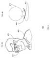
- FIG. 4Aillustrates a person 402 wearing head-mounted display.
- Examples of head-at mounted displayare available at online URL (www.i-glasses.com).
- These glasseshave lenses that allow the viewer to perceive an image that looks similar to a large screen TV or computer monitor. In addition the image is always directly in front of the person whichever way they move their head.
- These glassestypically have earphones 406 that allow for stereo sound.
- the PC or portable game appliancethat supplies the image to the user and also allows for it's interaction using, for example user buttons.
- the glassesare typically built so as to shade ambient light.
- FIG. 4Bis an elevational top view of the head-mounted display of FIG. 4 A.
- circle 410is an ideal top view of the person with the ideal display rendered as 408 . Note that the two displays 412 are seen as one image.
- the head mounted system 400is an excellent platform to further engross viewers of multimedia presentations such as games and movies.
- the head mounted system 400limits out side stimulus and provides only the intended audio and visual stimulus. However note that this does not provide for any visuals that are intended but outside the normal image area. Accordingly, a need exists for users of head mounted system 400 with a method and apparatus to improve the visual perception outside the normal image area.
- FIG. 5is an illustration 500 of a user 502 playing a hand-held computer game 502 .
- These hand-held unitsmade by for example: SEGATM, NintendoTM, and SonyTM are designed to be self-contained.
- the player 502interacts with the hand-held 506 with their hands 504 .
- the display 508 and an optional speaker 510are integrated into the hand-held unit 506 . This permits the hand-held unit 506 to be very portable. This allows the ambient noise and light to effect the users enjoyment, making it very difficult to become completely engrossed in the action.
- a method to present auxiliary lighting for enhancing a scene during a multimedia presentationcomprising the steps of: coupling one or more illumination sources over a network, so that at least one illumination source of the one or more illumination sources is capable of being uniquely addressed; displaying a multimedia presentation; reading a series of preprogrammed illumination identifiers stored in computer readable medium corresponding with the multimedia presentation; interpreting one or more illumination identifiers to set one or more illumination sources for a period of time and to set the address of at least one of the one or more illumination sources; and sending a set signal in response to the interpretation of the one more illumination identifiers to one or more illumination sources over the network.
- a gaming helmetis disclosed as the photonic enclosure used to carry out the above method.
- a hand-held gaming unitsis disclosed with illumination sources to carry out the above method.
- FIG. 1is a perspective view of typical movie theater system.
- FIG. 2is the home theater counterpart to the movie theater of FIG. 1 .
- FIG. 3is a perspective illustration of a typical PC multimedia environment.
- FIG. 4Aillustrates a person wearing head-mounted display.
- FIG. 4Bis an elevational top view of the head-mounted display of FIG. 4 A.
- FIG. 5is an illustration of a user playing a hand-held computer game.
- FIG. 6is an illustration of the movie theater of FIG. 1 with illumination sources, according to the present invention.
- FIG. 7is an illustration of the home theater of FIG. 2 with illumination sources, according to the present invention.
- FIG. 8is an illustration of an exemplary central illumination source placement with respect to a television and speaker so as to project a mood in a room, according to the present invention.
- FIG. 9is an illustration of the typical PC multimedia environment of FIG. 3 with illumination sources, according to the present invention.
- FIG. 10Ais an illustration of the person wearing head-mounted display of FIG. 4A with illumination sources, according to the present invention.
- FIG. 10Bis an elevational top view of the head-mounted display of FIG. 4B with illumination sources, according to the present invention.
- FIG. 11is an illustration of a user playing a hand-held computer game of FIG. 5 with illumination sources, according to the present invention.
- FIG. 12is a block diagram of a digital network, with one or more illumination sources that are capable of being uniquely addressed, according to the present invention.
- FIG. 13is a block diagram of an analog network, with one or more illumination sources that are capable of being uniquely addressed, according to the present invention.
- FIG. 14is a filter for separating an analog audio stream from the pre-programmed illumination identifiers, according to the present invention.
- FIG. 15is signal processor filter for triggering illumination sources from multimedia streams without preprogrammed illumination identifiers, according to the present invention.
- FIG. 16is a perspective view of a film with illumination identifiers stored on film tracks, according to the present invention.
- FIG. 17is a diagram illustrating the calculation of the lag period between a viewer's sight and sound perception, according to the present invention.
- Illumination sourceis any device that produces a light including an incandescent lamp, neon, florescent, LED (light emitting diode), sodium, mercury, Xeon, LASAR or in a chemical light source such as a glow stick.
- the illumination sourcemay respond to a simple on/off command, such as a household light switch. And in another embodiment, the illumination source may respond to a more complicated command such as an intensity level or with a defined profile. For example, a neon illumination source may commanded to be on for 1 ⁇ 2 second at full brightness.
- the illumination sourcemay be seen directly, or reflected, or viewed through fixed or changeable filters and or diffuser.
- the changeable filter or bulb selectionmay provide one or more colors to the light.
- the light sourcemay be a singular light source or two or more distinct light sources, such as those placed in a Pipe lighting.
- the illumination sourcemay be combined with other hardware such as speakers into a unit such as a lighting unit.
- MIDIMusical Instrument Digital Interface
- the command setincludes note-ons, note-offs, key velocity, pitch bend and other methods of controlling a synthesizer.
- the sound waves producedare those already stored in a wavetable in the receiving instrument or sound card. Since a MIDI file only represents player information, it is far more concise than formats that the sound directly. MIDI permits very small file size.
- Each lighting sourcemay be assigned a particular instrument from the MIDI standard. In the preferred embodiment, the instrument used an illumination identifier is an instrument not being used by the primary multimedia presentation.
- Networka wired or wireless connection coupling one or more illumination sources where at least one of the illumination sources is addressable.
- the addressmay be wired or wireless.
- Networksinclude X-10 bus, CE Bus, MIDI bus, RS422 bus, BitBusTM, Universal Serial Bus, parallel bus, serial bus, Ethernet, and IEEE 488.
- Night visionalso know as scotopic vision. Which is vision that is due to the activity of the rods, as opposed to the cones, of the retina for very low illumination conditions where only the difference of brightness but not of hue or color can be discerned.
- Photonic enclosurea simulated wide-angle viewing environment.
- a photonic enclosuremay used in a movie theater, a TV, a gaming or various PC environments.
- the presentation of light and its particular color, intensity, duration and exact locationare manifested with no limitation.
- Pipe lightingan illumination source in a clear tube.
- each of the illumination sourcesare depicted as a simple incandescent bulb, however other illumination sources are within the true scope and spirit of the present invention and the scope the present invention is not limited to a single bulb.
- FIG. 6shown is the movie theater setting 600 of FIG. 1 with illumination sources according to the present invention. Shown are five illumination sources, left front 602 , right front 604 , left rear 606 , right rear 608 , and center channel light 620 . These illumination sources are shown in close proximity to the surround sound speakers in this embodiment, but it should be understood that in other embodiments, the illumination sources can be placed at different locations within the movie theater 600 .
- the lightsare controlled to project a wide-angle illumination experience while watching the movie on screen 112 . These lights would be normally off and turned on only to give a feeling of light outside the normal field of view. The control of the lights are described further below.
- the lightsare synchronized to the action of the screen. For example an explosion happens from behind, the rear lights 606 and 608 are strobed to flash in time with the explosion. Note that there need not be any relationship between the intensity of this light, or it's color and the on going audio stream.
- the present invention's center illumination unit 620could be directly seen when it is turned on. Note that unlike the actual movie that is typically reflected off of the screen the center light can show light directly. Therefore the light can be more intense.
- the viewers in theater seating 114can be shown directly a strobe flash to help the illusion of an explosion. This light can also be used for what may be described as mood lighting.
- mood lightingOne example is a continuous soft blue glow simulation of being under water. This is caused by the center light shining up at the ceiling of the theater and not into the eyes of the viewers. In fact much care must be given not to “blind” the viewers.
- the present inventionprovides a surround lighting effect to augment the surround sound and to further engross the viewers in the movie or other multimedia presentation.
- This new photonic enclosureis much better than the current lighting in a theater. For example the display of a blinding flash of an explosion all the way down to a very dark lit night seen. This light can also be in different colors. Further the persistence of the light is brought into play. Once the eye is accustom to very little light the eye views only shades of gray. This is called night vision and one can be blinded temporally by a bright light or flash. This effect can be used as part of a story line.
- the spatial range of the viewernow extends off the screen all the way around the viewer.
- a night sceneis interrupted by a bright explosion of light that may be behind the viewer. Note that with the sound and the flash of the explosion in the back, and the movie is in the front the audience has the perception that it is “in” the movie and thereby become further engrossed in the movie.
- the layout and positioning of the illumination sources in the movie theater 600must be carefully chosen so as not to harm a viewer's eyesight especially with the use of lasers, or illumination source that have harmful effects because of the frequency of flashes.
- FIG. 7shows a home theater 700 of FIG. 2 with illumination sources according to the present invention.
- the illumination sourceshave been placed next to the speakers of FIG. 2 .
- Shownis a left front illumination source 702 , a right front illumination source 704 , a left rear illumination source 706 and a right rear illumination source 708 , a center illumination source 710 .
- the window 216is shown with a curtain 716 so as to assure a darkened room and the surround sound speakers have illumination sources next to each speaker cabinet.
- the center illumination unit 710is used for “mood” lighting by shining a particular color onto the ceiling, and or for effects such as explosions, or gunfire using a strobe.
- the TV viewing screen 212now has a total surround viewing experience for the home viewer while in the home seating, 214 .
- the center channel illumination source 710may be the only light needed. This would provide the mood lighting and strobe light with minimal installation cost or difficulty.
- FIG. 8is a side view 800 of the Central Illumination Source 710 .
- the central illumination source 710is behind the central speaker 218 mounted on top of the television 212 .
- the mood or flashing from the center illumination source 710reflects of the ceiling 814 and walls 812 are shown by simple ray traces 810 to project the mood of the multimedia presentation on the television 212 .
- the blue for under water, red for a fire, the strobe for explosions or gunfire, and other scenesare contemplated.
- FIG. 9is an illustration of the typical PC multimedia environment of FIG. 3 with illumination sources according to the present invention.
- the present inventionworks best if no un-controlled light is allowed into the room. Therefore the window has its curtain drawn 918 .
- the illumination sourcesare placed next to the speakers.
- the sub-woofer and center lighting unit 910are shown directly in front and below the PC's monitor 312 . It is noted that the Sub-Woofer and center lighting unit 910 , may be located together or independently. As with the home TV Theater care must be given not to harm the viewer's vision with this lighting.
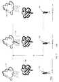
- FIG. 10Ais an illustration of the person wearing head-mounted display of FIG. 4A with illumination sources according to the present invention.
- a viewer 402 wearing head-mounted displayAs described above in FIG. 4A, illustrated in FIG. 10A is a viewer 402 wearing head-mounted display.
- Example manufacturers of head mounted displaysare available at online URL (www.i-glasses.com), or from the following companies, Albatche, Inc., Daeyang E&C, I_O Display Systems, LLC, Interactive Imaging Systems, Inc., Kaiser Electro-Optics, Inc., MicroOptical Corp., n-Vision, Inc., OpTech, Seattle Sight Systems, Inc., and Virtual Research Systems Inc.. This looks like a pair of glasses 404 but has very small displays built into the glasses.
- FIG. 10Bis an elevational top view of the head-mounted display of FIG. 4B with illumination sources according to the present invention. On the right, circle 410 is an ideal top view of the person with the ideal display rendered as 408 .
- the two displays 412are seen as one image.
- Three illumination sources 1004 , 1006 and 1008are connected inside the head mounted unit 1000 . It is important to note that the placement of the illumination sources 1004 , 1006 and 1008 be outside the direct view the person, so that when the illumination source is illuminated the person of the head mounted unit is able to visually perceive the illumination of the three illumination sources 1004 , 1006 , and 1008 while viewing the multimedia presentation.
- the light shield 1002besides reducing the amount of ambient outside light from being seen by the viewer 402 , it also enables the viewer to see lighting effects that are out side the viewer's normal viewing field using the illumination sources 1004 , 1006 and 1008 .
- the illumination sourceshave intensity and in one embodiment color shading to project modes during a scene. One effect is a flash during an explosion. Another example is a soft blue background light to simulate being under water. Note the one or more lights, 1004 , 1006 and 1008 that are placed just out of vision on the left, right and top of the viewer. These are used to help simulate light based events that are just out of site on the left, right or in back of the viewer such as an explosion or lighting from a thunder storm.
- the head-mounted display 404is not part of the head mounted unit 1000 .
- the viewer 402views a PC screen 312 or hand-held game display 508 through the head mounted unit 1000 .
- the light shield in this embodimentis eliminated to permit the direct viewing of the multimedia presentation on screen 312 or hand-held game display 508 .
- the illumination sources 1004 , 1006 and 1008again provide the surrounding illumination effects to the viewer 402 while watching the multimedia presentation outside the head mounted unit.
- the hand-held computer game 1100 of FIG. 5is now in the hands 1104 of the viewer 1102 .
- This hand-held 1106is designed with the subject invention lighting 1112 .
- the display 1108 and an optional speaker 1110are integrated into the hand-held unit 1106 .
- the unitcan also have lights built into the left and right side which would lighting effects that indicate actions to the left or right of the hand-held. These are not shown.
- the lightsare built into glasses that are wom by the hand-held user and flash around the user at the correct time and direction or in the head mounted unit of FIG. 10 .
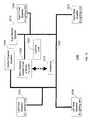
- FIG. 12is a block diagram 1200 of a digital network, with one or more illumination sources that are capable of being uniquely addressed, according to the present invention. Shown is digital serial bus implementation. Other bus implementations such as X-10, CE bus, MIDI bus, RS422 bus, BitBusTM, Universal Serial Bus, parallel bus, serial bus, Ethernet, and IEEE 488 are possible.
- the X-10 busallows for signals being deployed over existing AC power wiring which would not require any new wiring.
- a wireless solutioncan be used. It is important to note that the term “uniquely addressed” as used above includes a direct single analog connection to single light bulb or illumination source.
- the main viewing screen for a movie or TV or PCis reflected or projected through a viewing screen, 1202 .
- Thisis controlled by the video stream or by a controller or microprocessor (not shown).
- the rendering of the imagesis accompanied by the audio being reproduced by the speakers, 1204 , 1206 , 1208 , and 1210 that are deployed around the viewer(s) 1216 .
- the digital bus 1220allows for digital information to be sent for controlling the lighting units. This solution provides that all of the speakers and lights are connected to this bus 1220 .
- the left front speaker and lighting unit 1204produces the correct audio and light so as to simulate an audiovisual source off to the left of the screen.
- the right front speaker and lighting unit 1206 , the left rear speaker and lighting unit 1208 and finally the right rear speaker and lighting unit 1210all work in the same way from their respective locations.
- the sub-woofer speaker 1212is controlled so as to simulate effects that are felt.
- There is a center lighting unit 1222which is used for mood and or center of view flashes.
- the center channel speaker 1214controls normal surround sound audio for the user. Note that other solutions are possible that do not include all of the sited locations or functions.
- FIG. 13is a block diagram 1300 of an analog network, with one or more illumination sources that are capable of being uniquely controlled or addressed, according to the present invention. Shown are analog separate speaker wire implementation. The direct wired surround sound system, the present invention is implemented using these existing wires. Note that each speaker, 1304 , 1306 , 1308 , 1310 1312 and 1314 have an illumination source that is associated with the particular location. Specifically the main viewing screen 1302 is controlled from a home theater TV for movies or a PC for PC based games for the viewer(s) 1330 .
- analog network 1300 embodimentthere are six “speaker” wires 1316 , 1318 , 1320 , 1322 , 1324 , and 1326 to connected to speakers 1304 , 1306 , 1308 , 1310 , 1312 and 1314 .
- the present Inventionuse these wires 1316 , 1318 , 1320 , 1322 , 1324 , and 1326 to also control the lighting to the respective locations.
- the left front speaker and illumination source 1304are connected to the speaker wire 1316 .
- the right front speaker and illumination source 1306 , the left rear speaker and illumination source 1308 and finally the right rear speaker and illumination source 1310all work in the same way from their respective locations.
- the sub-woofer speaker and strobe illumination source 1312are controlled so as to simulate effects that are both aurally or acoustically felt and through illumination, that are beyond the normal capabilities of normal speakers and lighting.
- the center channel speaker and illumination source 1314provides normal audio and may act as mood lighting for the viewer.
- the technique for controlling a light with a digital or analog signal and sending the audio analog signalis described in FIG. 14 below. It is also noted that alternatively the subject invention can be implemented using additional direct connect wires. Yet another solution provides for a wireless solution. It is important to note, that the embodiments above provide total separation between the lighting and the audio in either the connections and/or the physical placements of the speakers and the illumination sources.
- FIG. 14is a filter for separating an analog audio stream from the pre-programmed illumination identifiers, according to the present invention.
- the art of coupling a control signal on to another signalis well understood.
- the audio signal 1402contains the electronic signal that is presented to the speaker 1408 for the desired audio affect based on the time line. Referring to the time between T 1 and T 2 the audio signal consists of only audio.
- the filter 1404has a high pass section 1404 A and low pass 1404 B section.
- the low pass section 1404 Bpasses the frequencies up to 20 Khz to the speaker.
- the high pass section 1404 Bpasses on the high frequency illumination identifiers.
- T 1 and T 2there are no illumination high frequency signals present, so the entire signal 1406 is presented to the speaker 1408 .
- a high frequency signalhas been added to the audio signal 1402 .
- this frequencyis too high for the speaker to reproduce, in addition it is outside the audio range of a human 20 Hz to 20 KHz.
- the high frequency signal 1410is removed from the normal audio 1406 .
- the speakerplays the normal audio during this time because the high frequency illumination identifier has been removed.
- This high frequency illumination identifier signal 1410is then used to create a light on signal 1412 . This is presented to the light 1416 , which is turned on during the times T 2 to T 3 .
- the input signal 1402contains only audio. Accordingly at this time the light 1416 goes out and the audio signal as filtered 1406 is unchanged and presented to the speaker 1408 .
- the illumination identifier on signal 1410 that was separated from the input audio signal 1402may contain additional digital information such as MIDI.
- the high frequency signalmay be correlated with a video stream so that the signature in a video of a bright gun flash (not shown) combined with the audio signature of the audio signal 1402 , provides triggering of illumination sources.
- the high frequency signalmay be replaced by a correlation for triggers contained in a NTSC, PAL, MPEG or similar video signal, where the triggering signals are part of a secondary channel such as close caption or language two.
- the triggering in this embodimentis off of key words “gun shot”, “explosion”, “campfire”, “underwater” and more.
- FIG. 15is signal processor for triggering illumination sources from multimedia streams without preprogrammed illumination identifiers, according to the present invention.
- an audio signal 1502that is normal, between T 1 and T 2 ( 1504 ).
- This signalis presented to both the speaker 1522 and a signal processor 1510 over input 1508 .
- the processor 1510can be implemented in analog, digital or a combination thereof and the circuitry herein of processor 1510 is exemplary only.
- the speakertransforms the electronic signal into one that is audio.
- T 2there is an audio signal that is very unique. Perhaps it is an explosion, or a gun-shot, or thunder. This unique signature is stored into a table 1516 along with an associated lighting effect.
- the audio signalis digitized 1512 and presented to a comparator circuit 1514 .
- itis compared to the pre-stored signatures 1516 and continuously looking for matches.
- the comparator 1514During the period of T 2 to T 3 , there is a match sensed by the comparator 1514 . This causes line 1518 to go active. This in turn, triggers the associated illumination effect from the Sound Signature Response Table 1520 to be presented to the light 1524 .
- the audio signaldoes not contain any matching light signatures and therefore only audio is presented to the viewer.
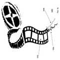
- FIG. 16is a perspective view 1600 of a film with illumination identifiers stored on film track 1606 according to the present invention.
- the filmsuch as 70 mm film, has a video area 1602 , and a sound track area 1604 .
- illumination identifiers in a track 1606are added during the production of the film for additional effects.
- the illumination identifiersare a MIDI sequence as described above.
- the illumination identifiers in the tracksare shown as part of a film track, it is important to note that the track of illumination identifiers could be part of a track in a DVD, Laserdisc, Video Cassette or other media such as the Internet were a primary multimedia presentation is being delivered, such as a movie.
- FIG. 17is a diagram illustrating the calculation of the delay period between a viewer's sight and sound perception, according to the present invention.
- a storm cloud 1702raining on to a tree 1704 and at a distance “d” to a viewer in the foreground 1706 .
- the distance “d” from the viewer 1706 to the tree 1704is about one Kilometer (1,000 meters).
- the timeis labeled as T 0 .
- the storm cloud 1702produces a lightning bolt 1708 to strike the tree 1704 .
- the viewer 1706can see the lightning bolt 1708 “instantly”.
- the sequence described in FIG. 17 of the delay between the flash of the lightning bolt 1708 and the thunderis many times lost when viewing this sequence in a television program of a movie.
- the producers of multimedia presentationcan set a delay for a period of time between a flash (e.g. lightning) and the sound (e.g. thunder) is heard by a viewer.
- the delay in the authoring of the illumination identifiersis set to correspond to a distance the average viewer would be viewing the multimedia presentation in which the sequence occurs prior to a sound.
- Exemplary scenes for flashes preceding a soundare explosions, a lighting flash, a gunshot, and a rocket launch.
- the following scenariosare included to provide examples of how the present invention may be used to enhance the viewer's experience of watching a primary multimedia source such as a game, television, and a movie. These viewer's experience are described using one or more of the illumination sources described above. It is important to note that in all the following scenarios, the viewers are viewing a primary multimedia presentation and the illumination sources are placed in the periphery of the primary multimedia presentation so as to be positioned outside the direct view of the viewer.
- Campfire scenarioIn a movie or computer game environment, the viewer is presented a dark night scene with the only light coming from the glow of a campfire. The ceiling and walls of the viewer's environment have a soft flickering red and orange glow.
- Gunfire scenarioIn a movie or computer game a darkened room has a flash from gunfire, in the scene there is a flash that lights up one side of the setting and the people. The flash that lights up the scene happens slightly out of the field of view.
- Explosion ScenarioIn a movie or computer game an explosion happens, causing a “blinding” flash of light.
- the flash of an explosionshould not only happen from the screen, but in fact totally surround the viewer.
- Night blindness scenarioIn a PC game a SWAT team is going from darkened room to darkened room looking of hostages. In one of the rooms the lights are turned on for a brief time and then off. For this scenario the darkened room has all of the lights turned on fully and game screen goes from very dark to very bright. This causes the SWAT team member (which is the game player) to have temporary night blindness. That is, unless the gamier has the discipline to close one eye that does not under go the temporary blindness once the lights are turned back off.
- Lightning ScenarioA lightning storm is approaching. As the storm approaches there is a soft flash from behind then after some seconds the soft rumble of thunder. The flash to the thunder is timed so as to indicate distance. After some time there is a brighter flash from behind and a louder rumble of thunder, that happens very shortly after the flash, as determined by the delay time calculated above. Finally with the storm “upon the viewer” a simultaneous flash of lighting, from all around the viewer and a very loud bang of thunder happens, which is accomplished with the illumination sources placed near the surround sound sources in the theater, television, PC and game environments described above.
- a Spinning ScenarioIn a movie or computer game an airplane (for example) is in a tight horizontal turn. As the viewer is looking forward the screen illustrates the horizon spinning with the sun going by once each turn. In addition the surrounding lighting effect are controlled so as to give the viewer the illusion that the sun is leaving the screen, going to the right, then behind then to the left and finally reentering the screen.
Landscapes
- Controls And Circuits For Display Device (AREA)
- Two-Way Televisions, Distribution Of Moving Picture Or The Like (AREA)
Abstract
Description
Claims (51)
Priority Applications (3)
| Application Number | Priority Date | Filing Date | Title |
|---|---|---|---|
| US09/588,953US6564108B1 (en) | 2000-06-07 | 2000-06-07 | Method and system of auxiliary illumination for enhancing a scene during a multimedia presentation |
| AU2001275353AAU2001275353A1 (en) | 2000-06-07 | 2001-06-07 | Method and system of auxiliary illumination for enhancing a scene during a multimedia presentation |
| PCT/US2001/018431WO2001095674A1 (en) | 2000-06-07 | 2001-06-07 | Method and system of auxiliary illumination for enhancing a scene during a multimedia presentation |
Applications Claiming Priority (1)
| Application Number | Priority Date | Filing Date | Title |
|---|---|---|---|
| US09/588,953US6564108B1 (en) | 2000-06-07 | 2000-06-07 | Method and system of auxiliary illumination for enhancing a scene during a multimedia presentation |
Publications (1)
| Publication Number | Publication Date |
|---|---|
| US6564108B1true US6564108B1 (en) | 2003-05-13 |
Family
ID=24355998
Family Applications (1)
| Application Number | Title | Priority Date | Filing Date |
|---|---|---|---|
| US09/588,953Expired - LifetimeUS6564108B1 (en) | 2000-06-07 | 2000-06-07 | Method and system of auxiliary illumination for enhancing a scene during a multimedia presentation |
Country Status (3)
| Country | Link |
|---|---|
| US (1) | US6564108B1 (en) |
| AU (1) | AU2001275353A1 (en) |
| WO (1) | WO2001095674A1 (en) |
Cited By (70)
| Publication number | Priority date | Publication date | Assignee | Title |
|---|---|---|---|---|
| US20020152045A1 (en)* | 1997-08-26 | 2002-10-17 | Kevin Dowling | Information systems |
| US20030036807A1 (en)* | 2001-08-14 | 2003-02-20 | Fosler Ross M. | Multiple master digital addressable lighting interface (DALI) system, method and apparatus |
| US20030057884A1 (en)* | 1997-12-17 | 2003-03-27 | Dowling Kevin J. | Systems and methods for digital entertainment |
| US20030100359A1 (en)* | 2000-10-04 | 2003-05-29 | Loose Timothy C. | Audio network for gaming machines |
| WO2004047426A3 (en)* | 2002-11-15 | 2004-07-15 | Esc Entertainment A California | Reality-based light environment for digital imaging in motion pictures |
| US20040139842A1 (en)* | 2003-01-17 | 2004-07-22 | David Brenner | Audio file format with mapped lighting effects and method for controlling lighting effects using an audio file format |
| US20040235545A1 (en)* | 2003-05-20 | 2004-11-25 | Landis David Alan | Method and system for playing interactive game |
| US20050282631A1 (en)* | 2003-01-16 | 2005-12-22 | Wms Gaming Inc. | Gaming machine with surround sound features |
| US20060011042A1 (en)* | 2004-07-16 | 2006-01-19 | Brenner David S | Audio file format with mapped vibrational effects and method for controlling vibrational effects using an audio file format |
| US20060058925A1 (en)* | 2002-07-04 | 2006-03-16 | Koninklijke Philips Electronics N.V. | Method of and system for controlling an ambient light and lighting unit |
| US20070091111A1 (en)* | 2004-01-05 | 2007-04-26 | Koninklijke Philips Electronics N.V. | Ambient light derived by subsampling video content and mapped through unrendered color space |
| US20070293148A1 (en)* | 2004-12-23 | 2007-12-20 | Chiang Kuo C | Portable video communication device with multi-illumination source |
| US20080133604A1 (en)* | 2006-11-28 | 2008-06-05 | Samsung Electronics Co., Ltd. | Apparatus and method for linking basic device and extended devices |
| US20080176654A1 (en)* | 2003-01-16 | 2008-07-24 | Loose Timothy C | Gaming machine environment having controlled audio media presentation |
| US20080299906A1 (en)* | 2007-06-04 | 2008-12-04 | Topway Electrical Appliance Company | Emulating playing apparatus of simulating games |
| US20080320126A1 (en)* | 2007-06-25 | 2008-12-25 | Microsoft Corporation | Environment sensing for interactive entertainment |
| US7479063B2 (en)* | 2000-10-04 | 2009-01-20 | Wms Gaming Inc. | Audio network for gaming machines |
| US20090058636A1 (en)* | 2007-08-31 | 2009-03-05 | Robert Gaskill | Wireless patient communicator employing security information management |
| US20090322955A1 (en)* | 2006-06-13 | 2009-12-31 | Takuya Iwanami | Data transmitting device, data transmitting method, audio-visual environment control device, audio-visual environment control system, and audio-visual environment control method |
| US7642730B2 (en) | 2000-04-24 | 2010-01-05 | Philips Solid-State Lighting Solutions, Inc. | Methods and apparatus for conveying information via color of light |
| US20100031298A1 (en)* | 2006-12-28 | 2010-02-04 | Sharp Kabushiki Kaisha | Transmission device, audio-visual environment control device, and audio-visual environment control system |
| USD616486S1 (en) | 2008-10-20 | 2010-05-25 | X6D Ltd. | 3D glasses |
| US20100213873A1 (en)* | 2009-02-23 | 2010-08-26 | Dominique Picard | System and method for light and color surround |
| US20100225468A1 (en)* | 2009-03-04 | 2010-09-09 | Jim Sievert | Modular Patient Portable Communicator for Use in Life Critical Network |
| CN101849436A (en)* | 2007-11-06 | 2010-09-29 | 皇家飞利浦电子股份有限公司 | Light management system for automatically identifying light effects available to a home entertainment system |
| US20100318201A1 (en)* | 2006-10-18 | 2010-12-16 | Ambx Uk Limited | Method and system for detecting effect of lighting device |
| CN101926226A (en)* | 2008-01-24 | 2010-12-22 | 皇家飞利浦电子股份有限公司 | Light-based communication for configuration of light-sensing peripherals |
| US20100321284A1 (en)* | 2006-10-24 | 2010-12-23 | Koninklijde Philips Electronics N.V. | System, method and computer-readable medium for displaying light radiation |
| US20110201411A1 (en)* | 2008-10-21 | 2011-08-18 | Wms Gaming Inc. | Gaming Machine With Improved Lighting Arrangement |
| USD646451S1 (en) | 2009-03-30 | 2011-10-04 | X6D Limited | Cart for 3D glasses |
| USD650956S1 (en) | 2009-05-13 | 2011-12-20 | X6D Limited | Cart for 3D glasses |
| US20110316426A1 (en)* | 2006-12-28 | 2011-12-29 | Sharp Kabushiki Kaisha | Audio-visual environment control device, audio-visual environment control system and audio-visual environment control method |
| USD652860S1 (en) | 2008-10-20 | 2012-01-24 | X6D Limited | 3D glasses |
| US8172677B2 (en) | 2006-11-10 | 2012-05-08 | Wms Gaming Inc. | Wagering games using multi-level gaming structure |
| USD662965S1 (en) | 2010-02-04 | 2012-07-03 | X6D Limited | 3D glasses |
| USD664183S1 (en) | 2010-08-27 | 2012-07-24 | X6D Limited | 3D glasses |
| US8233103B2 (en) | 2008-11-17 | 2012-07-31 | X6D Limited | System for controlling the operation of a pair of 3D glasses having left and right liquid crystal viewing shutters |
| USD666663S1 (en) | 2008-10-20 | 2012-09-04 | X6D Limited | 3D glasses |
| USD669522S1 (en) | 2010-08-27 | 2012-10-23 | X6D Limited | 3D glasses |
| USD671590S1 (en) | 2010-09-10 | 2012-11-27 | X6D Limited | 3D glasses |
| USD672804S1 (en) | 2009-05-13 | 2012-12-18 | X6D Limited | 3D glasses |
| US20130147396A1 (en)* | 2011-12-07 | 2013-06-13 | Comcast Cable Communications, Llc | Dynamic Ambient Lighting |
| EP2605622A3 (en)* | 2011-12-15 | 2013-07-24 | Comcast Cable Communications, LLC | Dynamic ambient lighting |
| US8542326B2 (en) | 2008-11-17 | 2013-09-24 | X6D Limited | 3D shutter glasses for use with LCD displays |
| USD692941S1 (en) | 2009-11-16 | 2013-11-05 | X6D Limited | 3D glasses |
| US8651939B2 (en) | 2004-10-01 | 2014-02-18 | Igt | Gaming system having a plurality of adjacently arranged gaming machines and a mechanical moveable indicator operable to individually indicate the gaming machines |
| US8777757B2 (en) | 2012-09-26 | 2014-07-15 | Wms Gaming Inc. | Gaming machine having enhanced emotive lighting feature |
| US8812841B2 (en) | 2009-03-04 | 2014-08-19 | Cardiac Pacemakers, Inc. | Communications hub for use in life critical network |
| USD711959S1 (en) | 2012-08-10 | 2014-08-26 | X6D Limited | Glasses for amblyopia treatment |
| US8841847B2 (en) | 2003-01-17 | 2014-09-23 | Motorola Mobility Llc | Electronic device for controlling lighting effects using an audio file |
| WO2014153245A1 (en)* | 2013-03-14 | 2014-09-25 | Aliphcom | Network of speaker lights and wearable devices using intelligent connection managers |
| USRE45394E1 (en) | 2008-10-20 | 2015-03-03 | X6D Limited | 3D glasses |
| US9380443B2 (en) | 2013-03-12 | 2016-06-28 | Comcast Cable Communications, Llc | Immersive positioning and paring |
| US20160295662A1 (en)* | 2015-04-02 | 2016-10-06 | Elwha Llc | Systems and methods for controlling lighting based on a display |
| US20160295663A1 (en)* | 2015-04-02 | 2016-10-06 | Elwha Llc | Systems and methods for controlling lighting based on a display |
| USD790740S1 (en)* | 2015-11-25 | 2017-06-27 | Innovative Technology Electronics, Llc | Christmas wreath with wireless strand speakers and additional lighting feature |
| USD790739S1 (en)* | 2015-11-25 | 2017-06-27 | Innovative Technology Electronics, Llc | Christmas garland with wireless strand speakers and additional lighting feature |
| USD796705S1 (en)* | 2015-07-09 | 2017-09-05 | Innovative Technology Electronics, Llc | Wireless strand speakers with additional lighting feature |
| WO2017162539A1 (en)* | 2016-03-22 | 2017-09-28 | Philips Lighting Holding B.V. | Lighting for video games |
| US9848058B2 (en) | 2007-08-31 | 2017-12-19 | Cardiac Pacemakers, Inc. | Medical data transport over wireless life critical network employing dynamic communication link mapping |
| US10019868B2 (en) | 2015-06-10 | 2018-07-10 | Bally Gaming, Inc. | Casino machine having emotive lighting structures |
| US10096202B2 (en) | 2015-06-10 | 2018-10-09 | Bally Gaming, Inc. | Casino machine having emotive lighting structures |
| US20190146445A1 (en)* | 2016-05-19 | 2019-05-16 | Azio Group Ag | Method and control device for controlling an appliance on the basis of a media file, computer program product, and building automation system |
| US10398003B2 (en) | 2013-03-13 | 2019-08-27 | Inception Innovations, Inc. | Color-changing lighting dynamic control |
| US10510222B2 (en) | 2015-04-29 | 2019-12-17 | Inception Innovations, Llc | Color-changing lighting dynamic control |
| US11433302B2 (en)* | 2017-10-16 | 2022-09-06 | Lego A/S | Interactive play apparatus |
| US11471756B2 (en)* | 2014-04-08 | 2022-10-18 | China Industries Limited | Interactive combat gaming system |
| WO2024119220A1 (en)* | 2022-12-09 | 2024-06-13 | Wgwg Pty Ltd | Video display ambient lighting synchronisation |
| US20240267603A1 (en)* | 2023-02-07 | 2024-08-08 | L3Harris Technologies, Inc. | Swir see-spot, laser target acquisition, tracking, and prf decoding nightvision system |
| US12295081B2 (en) | 2022-01-06 | 2025-05-06 | Comcast Cable Communications, Llc | Video display environmental lighting |
Families Citing this family (6)
| Publication number | Priority date | Publication date | Assignee | Title |
|---|---|---|---|---|
| CN101416563B (en) | 2006-03-31 | 2012-09-26 | Tp视觉控股有限公司 | Event based ambient lighting control |
| WO2007113740A1 (en)* | 2006-03-31 | 2007-10-11 | Koninklijke Philips Electronics, N.V. | Ambient lighting filter control |
| CA2865972C (en) | 2012-02-29 | 2022-01-04 | Pulmatrix, Inc. | Inhalable dry powders |
| FR3052569A1 (en)* | 2016-06-10 | 2017-12-15 | Orange | METHOD AND DEVICE FOR ADJUSTING BRIGHTNESS |
| EP3448127A1 (en)* | 2017-08-21 | 2019-02-27 | TP Vision Holding B.V. | Method for controlling light presentation of a light system during playback of a multimedia program |
| WO2019228969A1 (en)* | 2018-06-01 | 2019-12-05 | Signify Holding B.V. | Displaying a virtual dynamic light effect |
Citations (21)
| Publication number | Priority date | Publication date | Assignee | Title |
|---|---|---|---|---|
| US3806919A (en) | 1971-03-15 | 1974-04-23 | Lumatron Corp | Light organ |
| US4440059A (en) | 1981-12-18 | 1984-04-03 | Daniel Lee Egolf | Sound responsive lighting device with VCO driven indexing |
| US4471385A (en) | 1970-12-28 | 1984-09-11 | Hyatt Gilbert P | Electro-optical illumination control system |
| US4753148A (en) | 1986-12-01 | 1988-06-28 | Johnson Tom A | Sound emphasizer |
| FR2628335A1 (en) | 1988-03-09 | 1989-09-15 | Univ Alsace | Installation for controlling sound and light show - uses local communication and power interface connected to central control computer by network bus |
| US5113738A (en) | 1988-05-25 | 1992-05-19 | Darwin Krucoff | Recorded music enhancement system |
| US5275082A (en) | 1991-09-09 | 1994-01-04 | Kestner Clifton John N | Visual music conducting device |
| WO1995024796A1 (en) | 1994-03-08 | 1995-09-14 | Apple Computer, Inc. | Slectable audio/video (a/v) distribution using multi-media workstations, multi-channel a/v network, and digital data network |
| US5461188A (en) | 1994-03-07 | 1995-10-24 | Drago; Marcello S. | Synthesized music, sound and light system |
| US5519809A (en) | 1992-10-27 | 1996-05-21 | Technology International Incorporated | System and method for displaying geographical information |
| FR2741229A1 (en) | 1995-11-14 | 1997-05-16 | Brun Pierre | Lighting effect control system for operation in response to sound source |
| EP0786716A2 (en) | 1990-12-04 | 1997-07-30 | SONY ELECTRONICS INC. (a Delaware corporation) | Resource control apparatus |
| US5668537A (en)* | 1993-11-12 | 1997-09-16 | Chansky; Leonard M. | Theatrical lighting control network |
| US5784096A (en) | 1985-03-20 | 1998-07-21 | Paist; Roger M. | Dual audio signal derived color display |
| US5818342A (en) | 1995-10-03 | 1998-10-06 | Solomon; Lawrence | Audio responsive visual device |
| WO1999012119A2 (en) | 1997-08-29 | 1999-03-11 | Koninklijke Philips Electronics N.V. | Computer-controlled home theater with independent user-control |
| US5886304A (en) | 1996-02-20 | 1999-03-23 | Schlenzig; Dieter | Omni-directional sound system |
| US5896457A (en) | 1996-09-20 | 1999-04-20 | Sylvan F. Tyrrel | Light enhanced sound device and method |
| US5922982A (en) | 1996-04-19 | 1999-07-13 | Yamaha Corporation | Performance data generation apparatus for selectively outputting note on/off data based on performance operation mode |
| US5986201A (en) | 1996-10-30 | 1999-11-16 | Light And Sound Design, Ltd. | MIDI monitoring |
| US6050717A (en)* | 1996-05-15 | 2000-04-18 | Sony Corporation | Head-mounted image display having selective image suspension control and light adjustment |
- 2000
- 2000-06-07USUS09/588,953patent/US6564108B1/ennot_activeExpired - Lifetime
- 2001
- 2001-06-07AUAU2001275353Apatent/AU2001275353A1/ennot_activeAbandoned
- 2001-06-07WOPCT/US2001/018431patent/WO2001095674A1/enactiveApplication Filing
Patent Citations (22)
| Publication number | Priority date | Publication date | Assignee | Title |
|---|---|---|---|---|
| US4471385A (en) | 1970-12-28 | 1984-09-11 | Hyatt Gilbert P | Electro-optical illumination control system |
| US3806919A (en) | 1971-03-15 | 1974-04-23 | Lumatron Corp | Light organ |
| US4440059A (en) | 1981-12-18 | 1984-04-03 | Daniel Lee Egolf | Sound responsive lighting device with VCO driven indexing |
| US5784096A (en) | 1985-03-20 | 1998-07-21 | Paist; Roger M. | Dual audio signal derived color display |
| US4753148A (en) | 1986-12-01 | 1988-06-28 | Johnson Tom A | Sound emphasizer |
| FR2628335A1 (en) | 1988-03-09 | 1989-09-15 | Univ Alsace | Installation for controlling sound and light show - uses local communication and power interface connected to central control computer by network bus |
| US5113738A (en) | 1988-05-25 | 1992-05-19 | Darwin Krucoff | Recorded music enhancement system |
| EP0786716A2 (en) | 1990-12-04 | 1997-07-30 | SONY ELECTRONICS INC. (a Delaware corporation) | Resource control apparatus |
| US5275082A (en) | 1991-09-09 | 1994-01-04 | Kestner Clifton John N | Visual music conducting device |
| US5519809A (en) | 1992-10-27 | 1996-05-21 | Technology International Incorporated | System and method for displaying geographical information |
| US5668537A (en)* | 1993-11-12 | 1997-09-16 | Chansky; Leonard M. | Theatrical lighting control network |
| US6020825A (en) | 1993-11-12 | 2000-02-01 | Nsi Corporation | Theatrical lighting control network |
| US5461188A (en) | 1994-03-07 | 1995-10-24 | Drago; Marcello S. | Synthesized music, sound and light system |
| WO1995024796A1 (en) | 1994-03-08 | 1995-09-14 | Apple Computer, Inc. | Slectable audio/video (a/v) distribution using multi-media workstations, multi-channel a/v network, and digital data network |
| US5818342A (en) | 1995-10-03 | 1998-10-06 | Solomon; Lawrence | Audio responsive visual device |
| FR2741229A1 (en) | 1995-11-14 | 1997-05-16 | Brun Pierre | Lighting effect control system for operation in response to sound source |
| US5886304A (en) | 1996-02-20 | 1999-03-23 | Schlenzig; Dieter | Omni-directional sound system |
| US5922982A (en) | 1996-04-19 | 1999-07-13 | Yamaha Corporation | Performance data generation apparatus for selectively outputting note on/off data based on performance operation mode |
| US6050717A (en)* | 1996-05-15 | 2000-04-18 | Sony Corporation | Head-mounted image display having selective image suspension control and light adjustment |
| US5896457A (en) | 1996-09-20 | 1999-04-20 | Sylvan F. Tyrrel | Light enhanced sound device and method |
| US5986201A (en) | 1996-10-30 | 1999-11-16 | Light And Sound Design, Ltd. | MIDI monitoring |
| WO1999012119A2 (en) | 1997-08-29 | 1999-03-11 | Koninklijke Philips Electronics N.V. | Computer-controlled home theater with independent user-control |
Non-Patent Citations (2)
| Title |
|---|
| "An Overview of MIDI", The MIDI Companion (3 pgs.) (Date Unknown). |
| International Search Report dated Oct. 15, 2001 for International Application No. PCT/US01/18431. |
Cited By (117)
| Publication number | Priority date | Publication date | Assignee | Title |
|---|---|---|---|---|
| US7385359B2 (en) | 1997-08-26 | 2008-06-10 | Philips Solid-State Lighting Solutions, Inc. | Information systems |
| US20020152045A1 (en)* | 1997-08-26 | 2002-10-17 | Kevin Dowling | Information systems |
| US20050041161A1 (en)* | 1997-12-17 | 2005-02-24 | Color Kinetics, Incorporated | Systems and methods for digital entertainment |
| US20030057884A1 (en)* | 1997-12-17 | 2003-03-27 | Dowling Kevin J. | Systems and methods for digital entertainment |
| US7764026B2 (en) | 1997-12-17 | 2010-07-27 | Philips Solid-State Lighting Solutions, Inc. | Systems and methods for digital entertainment |
| US7642730B2 (en) | 2000-04-24 | 2010-01-05 | Philips Solid-State Lighting Solutions, Inc. | Methods and apparatus for conveying information via color of light |
| US20030100359A1 (en)* | 2000-10-04 | 2003-05-29 | Loose Timothy C. | Audio network for gaming machines |
| US7479063B2 (en)* | 2000-10-04 | 2009-01-20 | Wms Gaming Inc. | Audio network for gaming machines |
| US20030036807A1 (en)* | 2001-08-14 | 2003-02-20 | Fosler Ross M. | Multiple master digital addressable lighting interface (DALI) system, method and apparatus |
| US7369903B2 (en)* | 2002-07-04 | 2008-05-06 | Koninklijke Philips Electronics N.V. | Method of and system for controlling an ambient light and lighting unit |
| US20060058925A1 (en)* | 2002-07-04 | 2006-03-16 | Koninklijke Philips Electronics N.V. | Method of and system for controlling an ambient light and lighting unit |
| US7079137B2 (en) | 2002-11-15 | 2006-07-18 | Warner Bros. Entertainment Inc. | Method for digitally rendering an object using measured BRDF data |
| US20040150643A1 (en)* | 2002-11-15 | 2004-08-05 | George Borshukov | Method for digitally rendering an object using measured BRDF data |
| US6983082B2 (en) | 2002-11-15 | 2006-01-03 | Warner Bros. Entertainment Inc. | Reality-based light environment for digital imaging in motion pictures |
| US20040150641A1 (en)* | 2002-11-15 | 2004-08-05 | Esc Entertainment | Reality-based light environment for digital imaging in motion pictures |
| WO2004047426A3 (en)* | 2002-11-15 | 2004-07-15 | Esc Entertainment A California | Reality-based light environment for digital imaging in motion pictures |
| US20040169656A1 (en)* | 2002-11-15 | 2004-09-02 | David Piponi Daniele Paolo | Method for motion simulation of an articulated figure using animation input |
| US9495828B2 (en) | 2003-01-16 | 2016-11-15 | Bally Gaming, Inc. | Gaming machine environment having controlled audio media presentation |
| US20100261523A1 (en)* | 2003-01-16 | 2010-10-14 | Wms Gaming Inc. | Gaming Machine With Surround Sound Features |
| US20100151945A2 (en)* | 2003-01-16 | 2010-06-17 | Wms Gaming Inc. | Gaming Machine With Surround Sound Features |
| US8545320B2 (en) | 2003-01-16 | 2013-10-01 | Wms Gaming Inc. | Gaming machine with surround sound features |
| US7766747B2 (en) | 2003-01-16 | 2010-08-03 | Wms Gaming Inc. | Gaming machine with surround sound features |
| US20080176654A1 (en)* | 2003-01-16 | 2008-07-24 | Loose Timothy C | Gaming machine environment having controlled audio media presentation |
| US20050282631A1 (en)* | 2003-01-16 | 2005-12-22 | Wms Gaming Inc. | Gaming machine with surround sound features |
| US9005023B2 (en) | 2003-01-16 | 2015-04-14 | Wms Gaming Inc. | Gaming machine with surround sound features |
| US8008561B2 (en)* | 2003-01-17 | 2011-08-30 | Motorola Mobility, Inc. | Audio file format with mapped lighting effects and method for controlling lighting effects using an audio file format |
| US8841847B2 (en) | 2003-01-17 | 2014-09-23 | Motorola Mobility Llc | Electronic device for controlling lighting effects using an audio file |
| US20040139842A1 (en)* | 2003-01-17 | 2004-07-22 | David Brenner | Audio file format with mapped lighting effects and method for controlling lighting effects using an audio file format |
| WO2004068837A3 (en)* | 2003-01-17 | 2004-12-29 | Motorola Inc | An audio file format with mapped lighting effects and method for controlling lighting effects using an audio file format |
| US20040235545A1 (en)* | 2003-05-20 | 2004-11-25 | Landis David Alan | Method and system for playing interactive game |
| US20070091111A1 (en)* | 2004-01-05 | 2007-04-26 | Koninklijke Philips Electronics N.V. | Ambient light derived by subsampling video content and mapped through unrendered color space |
| US8115091B2 (en) | 2004-07-16 | 2012-02-14 | Motorola Mobility, Inc. | Method and device for controlling vibrational and light effects using instrument definitions in an audio file format |
| US20060011042A1 (en)* | 2004-07-16 | 2006-01-19 | Brenner David S | Audio file format with mapped vibrational effects and method for controlling vibrational effects using an audio file format |
| US8651939B2 (en) | 2004-10-01 | 2014-02-18 | Igt | Gaming system having a plurality of adjacently arranged gaming machines and a mechanical moveable indicator operable to individually indicate the gaming machines |
| US20070293148A1 (en)* | 2004-12-23 | 2007-12-20 | Chiang Kuo C | Portable video communication device with multi-illumination source |
| US20120007938A1 (en)* | 2004-12-23 | 2012-01-12 | Kuo-Ching Chiang | Portable communication device with multi-tasking module for parallelism |
| US20090322955A1 (en)* | 2006-06-13 | 2009-12-31 | Takuya Iwanami | Data transmitting device, data transmitting method, audio-visual environment control device, audio-visual environment control system, and audio-visual environment control method |
| US20100318201A1 (en)* | 2006-10-18 | 2010-12-16 | Ambx Uk Limited | Method and system for detecting effect of lighting device |
| US20100321284A1 (en)* | 2006-10-24 | 2010-12-23 | Koninklijde Philips Electronics N.V. | System, method and computer-readable medium for displaying light radiation |
| US8172677B2 (en) | 2006-11-10 | 2012-05-08 | Wms Gaming Inc. | Wagering games using multi-level gaming structure |
| US20080133604A1 (en)* | 2006-11-28 | 2008-06-05 | Samsung Electronics Co., Ltd. | Apparatus and method for linking basic device and extended devices |
| US20110316426A1 (en)* | 2006-12-28 | 2011-12-29 | Sharp Kabushiki Kaisha | Audio-visual environment control device, audio-visual environment control system and audio-visual environment control method |
| US20100031298A1 (en)* | 2006-12-28 | 2010-02-04 | Sharp Kabushiki Kaisha | Transmission device, audio-visual environment control device, and audio-visual environment control system |
| US20080299906A1 (en)* | 2007-06-04 | 2008-12-04 | Topway Electrical Appliance Company | Emulating playing apparatus of simulating games |
| US20080320126A1 (en)* | 2007-06-25 | 2008-12-25 | Microsoft Corporation | Environment sensing for interactive entertainment |
| US20090058636A1 (en)* | 2007-08-31 | 2009-03-05 | Robert Gaskill | Wireless patient communicator employing security information management |
| US8970392B2 (en) | 2007-08-31 | 2015-03-03 | Cardiac Pacemakers, Inc. | Medical data transport over wireless life critical network |
| US8515547B2 (en) | 2007-08-31 | 2013-08-20 | Cardiac Pacemakers, Inc. | Wireless patient communicator for use in a life critical network |
| US9848058B2 (en) | 2007-08-31 | 2017-12-19 | Cardiac Pacemakers, Inc. | Medical data transport over wireless life critical network employing dynamic communication link mapping |
| US7978062B2 (en) | 2007-08-31 | 2011-07-12 | Cardiac Pacemakers, Inc. | Medical data transport over wireless life critical network |
| US8818522B2 (en) | 2007-08-31 | 2014-08-26 | Cardiac Pacemakers, Inc. | Wireless patient communicator for use in a life critical network |
| US8395498B2 (en) | 2007-08-31 | 2013-03-12 | Cardiac Pacemakers, Inc. | Wireless patient communicator employing security information management |
| US8587427B2 (en) | 2007-08-31 | 2013-11-19 | Cardiac Pacemakers, Inc. | Medical data transport over wireless life critical network |
| US9269251B2 (en) | 2007-08-31 | 2016-02-23 | Cardiac Pacemakers, Inc. | Medical data transport over wireless life critical network |
| US8373556B2 (en) | 2007-08-31 | 2013-02-12 | Cardiac Pacemakers, Inc. | Medical data transport over wireless life critical network |
| CN101849436B (en)* | 2007-11-06 | 2014-12-03 | 皇家飞利浦电子股份有限公司 | Light management system that automatically recognizes light effects that can be used in home entertainment systems |
| US20100244745A1 (en)* | 2007-11-06 | 2010-09-30 | Koninklijke Philips Electronics N.V. | Light management system with automatic identification of light effects available for a home entertainment system |
| CN101849436A (en)* | 2007-11-06 | 2010-09-29 | 皇家飞利浦电子股份有限公司 | Light management system for automatically identifying light effects available to a home entertainment system |
| US8352079B2 (en)* | 2007-11-06 | 2013-01-08 | Koninklijke Philips Electronics N.V. | Light management system with automatic identification of light effects available for a home entertainment system |
| CN101926226A (en)* | 2008-01-24 | 2010-12-22 | 皇家飞利浦电子股份有限公司 | Light-based communication for configuration of light-sensing peripherals |
| USRE45394E1 (en) | 2008-10-20 | 2015-03-03 | X6D Limited | 3D glasses |
| USD650003S1 (en) | 2008-10-20 | 2011-12-06 | X6D Limited | 3D glasses |
| USD652860S1 (en) | 2008-10-20 | 2012-01-24 | X6D Limited | 3D glasses |
| USD616486S1 (en) | 2008-10-20 | 2010-05-25 | X6D Ltd. | 3D glasses |
| USD666663S1 (en) | 2008-10-20 | 2012-09-04 | X6D Limited | 3D glasses |
| US20110201411A1 (en)* | 2008-10-21 | 2011-08-18 | Wms Gaming Inc. | Gaming Machine With Improved Lighting Arrangement |
| US8376839B2 (en)* | 2008-10-21 | 2013-02-19 | Wms Gaming Inc. | Gaming machine with improved lighting arrangement |
| US8233103B2 (en) | 2008-11-17 | 2012-07-31 | X6D Limited | System for controlling the operation of a pair of 3D glasses having left and right liquid crystal viewing shutters |
| US8542326B2 (en) | 2008-11-17 | 2013-09-24 | X6D Limited | 3D shutter glasses for use with LCD displays |
| US8262228B2 (en)* | 2009-02-23 | 2012-09-11 | International Business Machines Corporation | Light and color surround |
| US20100213873A1 (en)* | 2009-02-23 | 2010-08-26 | Dominique Picard | System and method for light and color surround |
| US9313192B2 (en) | 2009-03-04 | 2016-04-12 | Cardiac Pacemakers, Inc. | Communications hub for use in life critical network |
| US8319631B2 (en) | 2009-03-04 | 2012-11-27 | Cardiac Pacemakers, Inc. | Modular patient portable communicator for use in life critical network |
| US8638221B2 (en) | 2009-03-04 | 2014-01-28 | Cardiac Pacemakers, Inc. | Modular patient communicator for use in life critical network |
| US9552722B2 (en) | 2009-03-04 | 2017-01-24 | Cardiac Pacemakers, Inc. | Modular communicator for use in life critical network |
| US20100225468A1 (en)* | 2009-03-04 | 2010-09-09 | Jim Sievert | Modular Patient Portable Communicator for Use in Life Critical Network |
| US8812841B2 (en) | 2009-03-04 | 2014-08-19 | Cardiac Pacemakers, Inc. | Communications hub for use in life critical network |
| USD646451S1 (en) | 2009-03-30 | 2011-10-04 | X6D Limited | Cart for 3D glasses |
| USD650956S1 (en) | 2009-05-13 | 2011-12-20 | X6D Limited | Cart for 3D glasses |
| USD672804S1 (en) | 2009-05-13 | 2012-12-18 | X6D Limited | 3D glasses |
| USD692941S1 (en) | 2009-11-16 | 2013-11-05 | X6D Limited | 3D glasses |
| USD662965S1 (en) | 2010-02-04 | 2012-07-03 | X6D Limited | 3D glasses |
| USD669522S1 (en) | 2010-08-27 | 2012-10-23 | X6D Limited | 3D glasses |
| USD664183S1 (en) | 2010-08-27 | 2012-07-24 | X6D Limited | 3D glasses |
| USD671590S1 (en) | 2010-09-10 | 2012-11-27 | X6D Limited | 3D glasses |
| US8878991B2 (en) | 2011-12-07 | 2014-11-04 | Comcast Cable Communications, Llc | Dynamic ambient lighting |
| US9084312B2 (en)* | 2011-12-07 | 2015-07-14 | Comcast Cable Communications, Llc | Dynamic ambient lighting |
| US20130147396A1 (en)* | 2011-12-07 | 2013-06-13 | Comcast Cable Communications, Llc | Dynamic Ambient Lighting |
| EP2605622A3 (en)* | 2011-12-15 | 2013-07-24 | Comcast Cable Communications, LLC | Dynamic ambient lighting |
| USD711959S1 (en) | 2012-08-10 | 2014-08-26 | X6D Limited | Glasses for amblyopia treatment |
| US8777757B2 (en) | 2012-09-26 | 2014-07-15 | Wms Gaming Inc. | Gaming machine having enhanced emotive lighting feature |
| US9380443B2 (en) | 2013-03-12 | 2016-06-28 | Comcast Cable Communications, Llc | Immersive positioning and paring |
| US10398003B2 (en) | 2013-03-13 | 2019-08-27 | Inception Innovations, Inc. | Color-changing lighting dynamic control |
| WO2014153245A1 (en)* | 2013-03-14 | 2014-09-25 | Aliphcom | Network of speaker lights and wearable devices using intelligent connection managers |
| US11471756B2 (en)* | 2014-04-08 | 2022-10-18 | China Industries Limited | Interactive combat gaming system |
| US20160295662A1 (en)* | 2015-04-02 | 2016-10-06 | Elwha Llc | Systems and methods for controlling lighting based on a display |
| US9678494B2 (en)* | 2015-04-02 | 2017-06-13 | Elwha Llc | Systems and methods for controlling lighting based on a display |
| US9681525B2 (en)* | 2015-04-02 | 2017-06-13 | Elwha Llc | Systems and methods for controlling lighting based on a display |
| US20160295663A1 (en)* | 2015-04-02 | 2016-10-06 | Elwha Llc | Systems and methods for controlling lighting based on a display |
| US10510222B2 (en) | 2015-04-29 | 2019-12-17 | Inception Innovations, Llc | Color-changing lighting dynamic control |
| US10096202B2 (en) | 2015-06-10 | 2018-10-09 | Bally Gaming, Inc. | Casino machine having emotive lighting structures |
| US10019868B2 (en) | 2015-06-10 | 2018-07-10 | Bally Gaming, Inc. | Casino machine having emotive lighting structures |
| US10789805B2 (en) | 2015-06-10 | 2020-09-29 | Sg Gaming, Inc. | Casino machine having emotive lighting structures |
| USD796705S1 (en)* | 2015-07-09 | 2017-09-05 | Innovative Technology Electronics, Llc | Wireless strand speakers with additional lighting feature |
| USD790739S1 (en)* | 2015-11-25 | 2017-06-27 | Innovative Technology Electronics, Llc | Christmas garland with wireless strand speakers and additional lighting feature |
| USD790740S1 (en)* | 2015-11-25 | 2017-06-27 | Innovative Technology Electronics, Llc | Christmas wreath with wireless strand speakers and additional lighting feature |
| WO2017162539A1 (en)* | 2016-03-22 | 2017-09-28 | Philips Lighting Holding B.V. | Lighting for video games |
| US10653951B2 (en) | 2016-03-22 | 2020-05-19 | Signify Holding B.V. | Lighting for video games |
| JP2019515706A (en)* | 2016-03-22 | 2019-06-13 | シグニファイ ホールディング ビー ヴィ | Lighting for video games |
| US20190146445A1 (en)* | 2016-05-19 | 2019-05-16 | Azio Group Ag | Method and control device for controlling an appliance on the basis of a media file, computer program product, and building automation system |
| US11433302B2 (en)* | 2017-10-16 | 2022-09-06 | Lego A/S | Interactive play apparatus |
| US12295081B2 (en) | 2022-01-06 | 2025-05-06 | Comcast Cable Communications, Llc | Video display environmental lighting |
| WO2024119220A1 (en)* | 2022-12-09 | 2024-06-13 | Wgwg Pty Ltd | Video display ambient lighting synchronisation |
| GB2630210A (en)* | 2022-12-09 | 2024-11-20 | Wgwg Pty Ltd | Video display ambient lighting synchronisation |
| US20250211811A1 (en)* | 2022-12-09 | 2025-06-26 | Wgwg Pty Ltd | Video display ambient lighting synchronisation |
| US20240267603A1 (en)* | 2023-02-07 | 2024-08-08 | L3Harris Technologies, Inc. | Swir see-spot, laser target acquisition, tracking, and prf decoding nightvision system |
| US12250438B2 (en)* | 2023-02-07 | 2025-03-11 | L3Harris Technologies, Inc. | Swir see-spot, laser target acquisition, tracking, and PRF decoding nightvision system |
Also Published As
| Publication number | Publication date |
|---|---|
| AU2001275353A1 (en) | 2001-12-17 |
| WO2001095674A1 (en) | 2001-12-13 |
Similar Documents
| Publication | Publication Date | Title |
|---|---|---|
| US6564108B1 (en) | Method and system of auxiliary illumination for enhancing a scene during a multimedia presentation | |
| US7180529B2 (en) | Immersive image viewing system and method | |
| US11885147B2 (en) | Large format theater design | |
| CN210021183U (en) | Immersive interactive panoramic holographic theater and performance system | |
| CN102100081B (en) | Additional Data Generation System | |
| US10907371B2 (en) | Large format theater design | |
| US20190166674A1 (en) | An ambience control system | |
| US9219910B2 (en) | Volumetric display system blending two light types to provide a new display medium | |
| WO2007123008A1 (en) | Data transmission device, data transmission method, audio-visual environment control device, audio-visual environment control system, and audio-visual environment control method | |
| US9805767B1 (en) | Perspective view entertainment system and method | |
| EP3288345B1 (en) | A method of controlling lighting sources, corresponding system and computer program product | |
| WO2018195652A1 (en) | System, method and apparatus for co-locating visual images and associated sound | |
| JP2023175742A (en) | Game machine | |
| US7740531B2 (en) | Operation of a set of devices | |
| EP3288344B1 (en) | A method of controlling lighting sources, corresponding system and computer program product | |
| US20140104293A1 (en) | Ambient light effect in video gaming | |
| CN103780915A (en) | Video files that include ambient light effects | |
| JP3277109B2 (en) | Image display device | |
| Novy | Computational immersive displays | |
| CN104735597A (en) | Immersion type holographic sound and 3D image fusion achieving system | |
| CN210713979U (en) | Virtual host theater based on AR technology | |
| KR20000012267A (en) | The remote virtual hall for realizing the effect of controlling lights | |
| JP2016166928A (en) | Performance device, performance method, program, and amusement system | |
| TW202320541A (en) | Immersive led display theater system | |
| WO2025019440A1 (en) | Multi-sensory object renderer |
Legal Events
| Date | Code | Title | Description |
|---|---|---|---|
| AS | Assignment | Owner name:DELFIN PROJECT, INC., THE, FLORIDA Free format text:ASSIGNMENT OF ASSIGNORS INTEREST;ASSIGNORS:MAKAR, MICHAEL G.;MOSLEY, JOSEPH M.;TINDALL, TRACY A.;REEL/FRAME:010875/0480 Effective date:20000606 | |
| AS | Assignment | Owner name:DELFIN PROJECT, INC.,THE, FLORIDA Free format text:ATTACHED IS A NEW ASSIGNMENT RECORDATION COVER SHEET TO CORRECT AN ERROR IN THE ASSIGNEE'S ZIP CODE,FOR THE ASSIGNMENT RECORDED 6/7/00 ON REEL/FRAME 010875/0480;ASSIGNORS:MAKAR, MICHAEL G.;MOSLEY, JOSEPH M.;TINDALL, TRACY A.;REEL/FRAME:011113/0869 Effective date:20000606 | |
| STCF | Information on status: patent grant | Free format text:PATENTED CASE | |
| CC | Certificate of correction | ||
| FPAY | Fee payment | Year of fee payment:4 | |
| SULP | Surcharge for late payment | ||
| AS | Assignment | Owner name:RESOURCE CONSORTIUM LIMITED, VIRGIN ISLANDS, BRITI Free format text:ASSIGNMENT OF ASSIGNORS INTEREST;ASSIGNOR:THE DELFIN PROJECT, INC.;REEL/FRAME:019171/0300 Effective date:20070130 | |
| FEPP | Fee payment procedure | Free format text:PAT HOLDER NO LONGER CLAIMS SMALL ENTITY STATUS, ENTITY STATUS SET TO UNDISCOUNTED (ORIGINAL EVENT CODE: STOL); ENTITY STATUS OF PATENT OWNER: LARGE ENTITY | |
| FPAY | Fee payment | Year of fee payment:8 | |
| FPAY | Fee payment | Year of fee payment:12 | |
| AS | Assignment | Owner name:RESOURCE CONSORTIUM LIMITED, LLC, DELAWARE Free format text:RE-DOMESTICATION AND ENTITY CONVERSION;ASSIGNOR:RESOURCE CONSORTIUM LIMITED;REEL/FRAME:050091/0297 Effective date:20190621 |