US6564087B1 - Fiber optic needle probes for optical coherence tomography imaging - Google Patents
Fiber optic needle probes for optical coherence tomography imagingDownload PDFInfo
- Publication number
- US6564087B1 US6564087B1US09/359,574US35957499AUS6564087B1US 6564087 B1US6564087 B1US 6564087B1US 35957499 AUS35957499 AUS 35957499AUS 6564087 B1US6564087 B1US 6564087B1
- Authority
- US
- United States
- Prior art keywords
- needle
- optical fiber
- fiber
- optical
- fiber optic
- Prior art date
- Legal status (The legal status is an assumption and is not a legal conclusion. Google has not performed a legal analysis and makes no representation as to the accuracy of the status listed.)
- Expired - Fee Related
Links
- HGWUUOXXAIISDB-UHFFFAOYSA-NC1C2C1CNC2Chemical compoundC1C2C1CNC2HGWUUOXXAIISDB-UHFFFAOYSA-N0.000description1
Images


Classifications
- A—HUMAN NECESSITIES
- A61—MEDICAL OR VETERINARY SCIENCE; HYGIENE
- A61B—DIAGNOSIS; SURGERY; IDENTIFICATION
- A61B5/00—Measuring for diagnostic purposes; Identification of persons
- A61B5/68—Arrangements of detecting, measuring or recording means, e.g. sensors, in relation to patient
- A61B5/6846—Arrangements of detecting, measuring or recording means, e.g. sensors, in relation to patient specially adapted to be brought in contact with an internal body part, i.e. invasive
- A61B5/6847—Arrangements of detecting, measuring or recording means, e.g. sensors, in relation to patient specially adapted to be brought in contact with an internal body part, i.e. invasive mounted on an invasive device
- A61B5/6852—Catheters
- A—HUMAN NECESSITIES
- A61—MEDICAL OR VETERINARY SCIENCE; HYGIENE
- A61B—DIAGNOSIS; SURGERY; IDENTIFICATION
- A61B1/00—Instruments for performing medical examinations of the interior of cavities or tubes of the body by visual or photographical inspection, e.g. endoscopes; Illuminating arrangements therefor
- A61B1/00163—Optical arrangements
- A61B1/00172—Optical arrangements with means for scanning
- A—HUMAN NECESSITIES
- A61—MEDICAL OR VETERINARY SCIENCE; HYGIENE
- A61B—DIAGNOSIS; SURGERY; IDENTIFICATION
- A61B1/00—Instruments for performing medical examinations of the interior of cavities or tubes of the body by visual or photographical inspection, e.g. endoscopes; Illuminating arrangements therefor
- A61B1/00163—Optical arrangements
- A61B1/00174—Optical arrangements characterised by the viewing angles
- A61B1/00183—Optical arrangements characterised by the viewing angles for variable viewing angles
- A—HUMAN NECESSITIES
- A61—MEDICAL OR VETERINARY SCIENCE; HYGIENE
- A61B—DIAGNOSIS; SURGERY; IDENTIFICATION
- A61B5/00—Measuring for diagnostic purposes; Identification of persons
- A61B5/0059—Measuring for diagnostic purposes; Identification of persons using light, e.g. diagnosis by transillumination, diascopy, fluorescence
- A61B5/0062—Arrangements for scanning
- A61B5/0064—Body surface scanning
- A—HUMAN NECESSITIES
- A61—MEDICAL OR VETERINARY SCIENCE; HYGIENE
- A61B—DIAGNOSIS; SURGERY; IDENTIFICATION
- A61B5/00—Measuring for diagnostic purposes; Identification of persons
- A61B5/0059—Measuring for diagnostic purposes; Identification of persons using light, e.g. diagnosis by transillumination, diascopy, fluorescence
- A61B5/0062—Arrangements for scanning
- A61B5/0066—Optical coherence imaging
- A—HUMAN NECESSITIES
- A61—MEDICAL OR VETERINARY SCIENCE; HYGIENE
- A61B—DIAGNOSIS; SURGERY; IDENTIFICATION
- A61B5/00—Measuring for diagnostic purposes; Identification of persons
- A61B5/0059—Measuring for diagnostic purposes; Identification of persons using light, e.g. diagnosis by transillumination, diascopy, fluorescence
- A61B5/0082—Measuring for diagnostic purposes; Identification of persons using light, e.g. diagnosis by transillumination, diascopy, fluorescence adapted for particular medical purposes
- A61B5/0084—Measuring for diagnostic purposes; Identification of persons using light, e.g. diagnosis by transillumination, diascopy, fluorescence adapted for particular medical purposes for introduction into the body, e.g. by catheters
- A—HUMAN NECESSITIES
- A61—MEDICAL OR VETERINARY SCIENCE; HYGIENE
- A61B—DIAGNOSIS; SURGERY; IDENTIFICATION
- A61B5/00—Measuring for diagnostic purposes; Identification of persons
- A61B5/44—Detecting, measuring or recording for evaluating the integumentary system, e.g. skin, hair or nails
- A61B5/441—Skin evaluation, e.g. for skin disorder diagnosis
- A61B5/445—Evaluating skin irritation or skin trauma, e.g. rash, eczema, wound, bed sore
- A—HUMAN NECESSITIES
- A61—MEDICAL OR VETERINARY SCIENCE; HYGIENE
- A61B—DIAGNOSIS; SURGERY; IDENTIFICATION
- A61B5/00—Measuring for diagnostic purposes; Identification of persons
- A61B5/68—Arrangements of detecting, measuring or recording means, e.g. sensors, in relation to patient
- A61B5/6846—Arrangements of detecting, measuring or recording means, e.g. sensors, in relation to patient specially adapted to be brought in contact with an internal body part, i.e. invasive
- A61B5/6847—Arrangements of detecting, measuring or recording means, e.g. sensors, in relation to patient specially adapted to be brought in contact with an internal body part, i.e. invasive mounted on an invasive device
- A61B5/6848—Needles
- B—PERFORMING OPERATIONS; TRANSPORTING
- B82—NANOTECHNOLOGY
- B82Y—SPECIFIC USES OR APPLICATIONS OF NANOSTRUCTURES; MEASUREMENT OR ANALYSIS OF NANOSTRUCTURES; MANUFACTURE OR TREATMENT OF NANOSTRUCTURES
- B82Y15/00—Nanotechnology for interacting, sensing or actuating, e.g. quantum dots as markers in protein assays or molecular motors
- G—PHYSICS
- G01—MEASURING; TESTING
- G01B—MEASURING LENGTH, THICKNESS OR SIMILAR LINEAR DIMENSIONS; MEASURING ANGLES; MEASURING AREAS; MEASURING IRREGULARITIES OF SURFACES OR CONTOURS
- G01B11/00—Measuring arrangements characterised by the use of optical techniques
- G—PHYSICS
- G01—MEASURING; TESTING
- G01B—MEASURING LENGTH, THICKNESS OR SIMILAR LINEAR DIMENSIONS; MEASURING ANGLES; MEASURING AREAS; MEASURING IRREGULARITIES OF SURFACES OR CONTOURS
- G01B11/00—Measuring arrangements characterised by the use of optical techniques
- G01B11/02—Measuring arrangements characterised by the use of optical techniques for measuring length, width or thickness
- G01B11/026—Measuring arrangements characterised by the use of optical techniques for measuring length, width or thickness by measuring distance between sensor and object
- G—PHYSICS
- G01—MEASURING; TESTING
- G01B—MEASURING LENGTH, THICKNESS OR SIMILAR LINEAR DIMENSIONS; MEASURING ANGLES; MEASURING AREAS; MEASURING IRREGULARITIES OF SURFACES OR CONTOURS
- G01B11/00—Measuring arrangements characterised by the use of optical techniques
- G01B11/08—Measuring arrangements characterised by the use of optical techniques for measuring diameters
- G01B11/12—Measuring arrangements characterised by the use of optical techniques for measuring diameters internal diameters
- G—PHYSICS
- G01—MEASURING; TESTING
- G01B—MEASURING LENGTH, THICKNESS OR SIMILAR LINEAR DIMENSIONS; MEASURING ANGLES; MEASURING AREAS; MEASURING IRREGULARITIES OF SURFACES OR CONTOURS
- G01B11/00—Measuring arrangements characterised by the use of optical techniques
- G01B11/24—Measuring arrangements characterised by the use of optical techniques for measuring contours or curvatures
- G01B11/2441—Measuring arrangements characterised by the use of optical techniques for measuring contours or curvatures using interferometry
- G—PHYSICS
- G01—MEASURING; TESTING
- G01B—MEASURING LENGTH, THICKNESS OR SIMILAR LINEAR DIMENSIONS; MEASURING ANGLES; MEASURING AREAS; MEASURING IRREGULARITIES OF SURFACES OR CONTOURS
- G01B9/00—Measuring instruments characterised by the use of optical techniques
- G01B9/02—Interferometers
- G01B9/02049—Interferometers characterised by particular mechanical design details
- G01B9/0205—Interferometers characterised by particular mechanical design details of probe head
- G—PHYSICS
- G01—MEASURING; TESTING
- G01B—MEASURING LENGTH, THICKNESS OR SIMILAR LINEAR DIMENSIONS; MEASURING ANGLES; MEASURING AREAS; MEASURING IRREGULARITIES OF SURFACES OR CONTOURS
- G01B9/00—Measuring instruments characterised by the use of optical techniques
- G01B9/02—Interferometers
- G01B9/0209—Low-coherence interferometers
- G01B9/02091—Tomographic interferometers, e.g. based on optical coherence
- G—PHYSICS
- G01—MEASURING; TESTING
- G01J—MEASUREMENT OF INTENSITY, VELOCITY, SPECTRAL CONTENT, POLARISATION, PHASE OR PULSE CHARACTERISTICS OF INFRARED, VISIBLE OR ULTRAVIOLET LIGHT; COLORIMETRY; RADIATION PYROMETRY
- G01J1/00—Photometry, e.g. photographic exposure meter
- G—PHYSICS
- G01—MEASURING; TESTING
- G01N—INVESTIGATING OR ANALYSING MATERIALS BY DETERMINING THEIR CHEMICAL OR PHYSICAL PROPERTIES
- G01N21/00—Investigating or analysing materials by the use of optical means, i.e. using sub-millimetre waves, infrared, visible or ultraviolet light
- G01N21/17—Systems in which incident light is modified in accordance with the properties of the material investigated
- G01N21/47—Scattering, i.e. diffuse reflection
- G01N21/4795—Scattering, i.e. diffuse reflection spatially resolved investigating of object in scattering medium
- G—PHYSICS
- G02—OPTICS
- G02B—OPTICAL ELEMENTS, SYSTEMS OR APPARATUS
- G02B5/00—Optical elements other than lenses
- G02B5/18—Diffraction gratings
- G02B5/1828—Diffraction gratings having means for producing variable diffraction
- G—PHYSICS
- G11—INFORMATION STORAGE
- G11B—INFORMATION STORAGE BASED ON RELATIVE MOVEMENT BETWEEN RECORD CARRIER AND TRANSDUCER
- G11B7/00—Recording or reproducing by optical means, e.g. recording using a thermal beam of optical radiation by modifying optical properties or the physical structure, reproducing using an optical beam at lower power by sensing optical properties; Record carriers therefor
- G11B7/002—Recording, reproducing or erasing systems characterised by the shape or form of the carrier
- G11B7/0037—Recording, reproducing or erasing systems characterised by the shape or form of the carrier with discs
- G—PHYSICS
- G11—INFORMATION STORAGE
- G11B—INFORMATION STORAGE BASED ON RELATIVE MOVEMENT BETWEEN RECORD CARRIER AND TRANSDUCER
- G11B7/00—Recording or reproducing by optical means, e.g. recording using a thermal beam of optical radiation by modifying optical properties or the physical structure, reproducing using an optical beam at lower power by sensing optical properties; Record carriers therefor
- G11B7/004—Recording, reproducing or erasing methods; Read, write or erase circuits therefor
- G11B7/005—Reproducing
- G—PHYSICS
- G11—INFORMATION STORAGE
- G11B—INFORMATION STORAGE BASED ON RELATIVE MOVEMENT BETWEEN RECORD CARRIER AND TRANSDUCER
- G11B7/00—Recording or reproducing by optical means, e.g. recording using a thermal beam of optical radiation by modifying optical properties or the physical structure, reproducing using an optical beam at lower power by sensing optical properties; Record carriers therefor
- G11B7/08—Disposition or mounting of heads or light sources relatively to record carriers
- G11B7/085—Disposition or mounting of heads or light sources relatively to record carriers with provision for moving the light beam into, or out of, its operative position or across tracks, otherwise than during the transducing operation, e.g. for adjustment or preliminary positioning or track change or selection
- G11B7/08547—Arrangements for positioning the light beam only without moving the head, e.g. using static electro-optical elements
- G11B7/08564—Arrangements for positioning the light beam only without moving the head, e.g. using static electro-optical elements using galvanomirrors
- G—PHYSICS
- G11—INFORMATION STORAGE
- G11B—INFORMATION STORAGE BASED ON RELATIVE MOVEMENT BETWEEN RECORD CARRIER AND TRANSDUCER
- G11B7/00—Recording or reproducing by optical means, e.g. recording using a thermal beam of optical radiation by modifying optical properties or the physical structure, reproducing using an optical beam at lower power by sensing optical properties; Record carriers therefor
- G11B7/08—Disposition or mounting of heads or light sources relatively to record carriers
- G11B7/09—Disposition or mounting of heads or light sources relatively to record carriers with provision for moving the light beam or focus plane for the purpose of maintaining alignment of the light beam relative to the record carrier during transducing operation, e.g. to compensate for surface irregularities of the latter or for track following
- G11B7/0908—Disposition or mounting of heads or light sources relatively to record carriers with provision for moving the light beam or focus plane for the purpose of maintaining alignment of the light beam relative to the record carrier during transducing operation, e.g. to compensate for surface irregularities of the latter or for track following for focusing only
- G—PHYSICS
- G11—INFORMATION STORAGE
- G11B—INFORMATION STORAGE BASED ON RELATIVE MOVEMENT BETWEEN RECORD CARRIER AND TRANSDUCER
- G11B7/00—Recording or reproducing by optical means, e.g. recording using a thermal beam of optical radiation by modifying optical properties or the physical structure, reproducing using an optical beam at lower power by sensing optical properties; Record carriers therefor
- G11B7/12—Heads, e.g. forming of the optical beam spot or modulation of the optical beam
- G11B7/125—Optical beam sources therefor, e.g. laser control circuitry specially adapted for optical storage devices; Modulators, e.g. means for controlling the size or intensity of optical spots or optical traces
- G11B7/126—Circuits, methods or arrangements for laser control or stabilisation
- G—PHYSICS
- G11—INFORMATION STORAGE
- G11B—INFORMATION STORAGE BASED ON RELATIVE MOVEMENT BETWEEN RECORD CARRIER AND TRANSDUCER
- G11B7/00—Recording or reproducing by optical means, e.g. recording using a thermal beam of optical radiation by modifying optical properties or the physical structure, reproducing using an optical beam at lower power by sensing optical properties; Record carriers therefor
- G11B7/12—Heads, e.g. forming of the optical beam spot or modulation of the optical beam
- G11B7/125—Optical beam sources therefor, e.g. laser control circuitry specially adapted for optical storage devices; Modulators, e.g. means for controlling the size or intensity of optical spots or optical traces
- G11B7/127—Lasers; Multiple laser arrays
- G—PHYSICS
- G11—INFORMATION STORAGE
- G11B—INFORMATION STORAGE BASED ON RELATIVE MOVEMENT BETWEEN RECORD CARRIER AND TRANSDUCER
- G11B7/00—Recording or reproducing by optical means, e.g. recording using a thermal beam of optical radiation by modifying optical properties or the physical structure, reproducing using an optical beam at lower power by sensing optical properties; Record carriers therefor
- G11B7/12—Heads, e.g. forming of the optical beam spot or modulation of the optical beam
- G11B7/125—Optical beam sources therefor, e.g. laser control circuitry specially adapted for optical storage devices; Modulators, e.g. means for controlling the size or intensity of optical spots or optical traces
- G11B7/128—Modulators
- G—PHYSICS
- G11—INFORMATION STORAGE
- G11B—INFORMATION STORAGE BASED ON RELATIVE MOVEMENT BETWEEN RECORD CARRIER AND TRANSDUCER
- G11B7/00—Recording or reproducing by optical means, e.g. recording using a thermal beam of optical radiation by modifying optical properties or the physical structure, reproducing using an optical beam at lower power by sensing optical properties; Record carriers therefor
- G11B7/12—Heads, e.g. forming of the optical beam spot or modulation of the optical beam
- G11B7/135—Means for guiding the beam from the source to the record carrier or from the record carrier to the detector
- G11B7/1353—Diffractive elements, e.g. holograms or gratings
- G—PHYSICS
- G11—INFORMATION STORAGE
- G11B—INFORMATION STORAGE BASED ON RELATIVE MOVEMENT BETWEEN RECORD CARRIER AND TRANSDUCER
- G11B7/00—Recording or reproducing by optical means, e.g. recording using a thermal beam of optical radiation by modifying optical properties or the physical structure, reproducing using an optical beam at lower power by sensing optical properties; Record carriers therefor
- G11B7/12—Heads, e.g. forming of the optical beam spot or modulation of the optical beam
- G11B7/14—Heads, e.g. forming of the optical beam spot or modulation of the optical beam specially adapted to record on, or to reproduce from, more than one track simultaneously
- G—PHYSICS
- G11—INFORMATION STORAGE
- G11B—INFORMATION STORAGE BASED ON RELATIVE MOVEMENT BETWEEN RECORD CARRIER AND TRANSDUCER
- G11B7/00—Recording or reproducing by optical means, e.g. recording using a thermal beam of optical radiation by modifying optical properties or the physical structure, reproducing using an optical beam at lower power by sensing optical properties; Record carriers therefor
- G11B7/24—Record carriers characterised by shape, structure or physical properties, or by the selection of the material
- A—HUMAN NECESSITIES
- A61—MEDICAL OR VETERINARY SCIENCE; HYGIENE
- A61B—DIAGNOSIS; SURGERY; IDENTIFICATION
- A61B1/00—Instruments for performing medical examinations of the interior of cavities or tubes of the body by visual or photographical inspection, e.g. endoscopes; Illuminating arrangements therefor
- A61B1/00064—Constructional details of the endoscope body
- A61B1/00071—Insertion part of the endoscope body
- A61B1/0008—Insertion part of the endoscope body characterised by distal tip features
- A61B1/00096—Optical elements
- A—HUMAN NECESSITIES
- A61—MEDICAL OR VETERINARY SCIENCE; HYGIENE
- A61B—DIAGNOSIS; SURGERY; IDENTIFICATION
- A61B2562/00—Details of sensors; Constructional details of sensor housings or probes; Accessories for sensors
- A61B2562/02—Details of sensors specially adapted for in-vivo measurements
- A61B2562/0233—Special features of optical sensors or probes classified in A61B5/00
- A61B2562/0242—Special features of optical sensors or probes classified in A61B5/00 for varying or adjusting the optical path length in the tissue
- A—HUMAN NECESSITIES
- A61—MEDICAL OR VETERINARY SCIENCE; HYGIENE
- A61B—DIAGNOSIS; SURGERY; IDENTIFICATION
- A61B2562/00—Details of sensors; Constructional details of sensor housings or probes; Accessories for sensors
- A61B2562/02—Details of sensors specially adapted for in-vivo measurements
- A61B2562/028—Microscale sensors, e.g. electromechanical sensors [MEMS]
- A—HUMAN NECESSITIES
- A61—MEDICAL OR VETERINARY SCIENCE; HYGIENE
- A61B—DIAGNOSIS; SURGERY; IDENTIFICATION
- A61B3/00—Apparatus for testing the eyes; Instruments for examining the eyes
- A61B3/10—Objective types, i.e. instruments for examining the eyes independent of the patients' perceptions or reactions
- A61B3/1005—Objective types, i.e. instruments for examining the eyes independent of the patients' perceptions or reactions for measuring distances inside the eye, e.g. thickness of the cornea
- A—HUMAN NECESSITIES
- A61—MEDICAL OR VETERINARY SCIENCE; HYGIENE
- A61B—DIAGNOSIS; SURGERY; IDENTIFICATION
- A61B3/00—Apparatus for testing the eyes; Instruments for examining the eyes
- A61B3/10—Objective types, i.e. instruments for examining the eyes independent of the patients' perceptions or reactions
- A61B3/102—Objective types, i.e. instruments for examining the eyes independent of the patients' perceptions or reactions for optical coherence tomography [OCT]
- G—PHYSICS
- G01—MEASURING; TESTING
- G01B—MEASURING LENGTH, THICKNESS OR SIMILAR LINEAR DIMENSIONS; MEASURING ANGLES; MEASURING AREAS; MEASURING IRREGULARITIES OF SURFACES OR CONTOURS
- G01B2290/00—Aspects of interferometers not specifically covered by any group under G01B9/02
- G01B2290/65—Spatial scanning object beam
- G—PHYSICS
- G11—INFORMATION STORAGE
- G11B—INFORMATION STORAGE BASED ON RELATIVE MOVEMENT BETWEEN RECORD CARRIER AND TRANSDUCER
- G11B7/00—Recording or reproducing by optical means, e.g. recording using a thermal beam of optical radiation by modifying optical properties or the physical structure, reproducing using an optical beam at lower power by sensing optical properties; Record carriers therefor
- G11B2007/0003—Recording, reproducing or erasing systems characterised by the structure or type of the carrier
- G11B2007/0009—Recording, reproducing or erasing systems characterised by the structure or type of the carrier for carriers having data stored in three dimensions, e.g. volume storage
- G11B2007/0013—Recording, reproducing or erasing systems characterised by the structure or type of the carrier for carriers having data stored in three dimensions, e.g. volume storage for carriers having multiple discrete layers
- G—PHYSICS
- G11—INFORMATION STORAGE
- G11B—INFORMATION STORAGE BASED ON RELATIVE MOVEMENT BETWEEN RECORD CARRIER AND TRANSDUCER
- G11B7/00—Recording or reproducing by optical means, e.g. recording using a thermal beam of optical radiation by modifying optical properties or the physical structure, reproducing using an optical beam at lower power by sensing optical properties; Record carriers therefor
- G11B7/08—Disposition or mounting of heads or light sources relatively to record carriers
- G11B7/09—Disposition or mounting of heads or light sources relatively to record carriers with provision for moving the light beam or focus plane for the purpose of maintaining alignment of the light beam relative to the record carrier during transducing operation, e.g. to compensate for surface irregularities of the latter or for track following
- G11B7/0945—Methods for initialising servos, start-up sequences
- H—ELECTRICITY
- H01—ELECTRIC ELEMENTS
- H01S—DEVICES USING THE PROCESS OF LIGHT AMPLIFICATION BY STIMULATED EMISSION OF RADIATION [LASER] TO AMPLIFY OR GENERATE LIGHT; DEVICES USING STIMULATED EMISSION OF ELECTROMAGNETIC RADIATION IN WAVE RANGES OTHER THAN OPTICAL
- H01S5/00—Semiconductor lasers
- H01S5/10—Construction or shape of the optical resonator, e.g. extended or external cavity, coupled cavities, bent-guide, varying width, thickness or composition of the active region
- H01S5/14—External cavity lasers
- H01S5/141—External cavity lasers using a wavelength selective device, e.g. a grating or etalon
Definitions
- the present inventionrelates generally to fiber optic needle probes adapted for use in optical imaging systems.
- Optical imaging systemssuch as optical coherence tomography (OCT) systems generate images or measurements by measuring the intensity of light backscattered or backreflected from a specimen and providing a gray scale or false color two-dimensional representation of this light intensity in a plane or cross-section through the object being imaged or measured.
- OCToptical coherence tomography
- OCTenables the nonexcisional, in situ, real-time imaging of microstructure in a specimen with a resolution of approximately 2 to 10 microns.
- An OCT systemcan be separated into an imaging engine and probes.
- the imaging enginecontains the optical light source, optical interferometer and other optical detection elements, as well as electronics, motors, controller(s), and computers for image generation and display.
- the probesare modules which are attached to the engine and direct light to and from the specimen which is to be measured or imaged.
- the present inventionprovides a fiber optic needle probe adapted for use in an optical imaging system, particularly for use in imaging solid tissues and organs.
- the fiber optic needle probecan be inserted directly into a solid tissue or organ or through a tissue wall into the lumen of a hollow organ or space (such as into a sinus cavity or into a blood vessel).
- the fiber optic needle probecan be inserted with minimal trauma into a tissue because of its small diameter.
- the fiber optic needle probe of the present inventionenables optical measurement and imaging in regions of the body which are not accessible using existing catheter, endoscope, or laparoscope technology.
- the fiber optic needle probecomprises a needle having a tip and a wall defining a bore.
- the needleis sized and shaped for nonintraluminal insertion into a specimen.
- At least a portion of an optical fiberis positioned within the bore of the needle.
- the optical fiberis independently movable within the needle.
- the optical fiber and needlecomprise a single, integrated unit, i.e., the optical fiber is fixedly positioned within the needle and the needle and optical fiber move as one.
- a beam directoris positioned in close juxtaposition to, the first end of the optical fiber to direct light from the optical fiber to the specimen being imaged.
- the wall of the needlecomprises an optical port.
- the beam directoris positioned in close juxtaposition to the optical port and is capable or directing light and receiving light through the optical port.
- the portmay be configured to permit transmission of light along a plurality of points substantially linear with a longitudinal axis of the needle.
- the portis configured to permit transmission of light over a range of positions orthogonal to a longitudinal axis of the needle.
- the fiber optic needle probe needlecomprises a coring tube positioned within the bore of the needle.
- the optical fiberis positioned substantially within the coring tube (as used herein, “positioned substantially” means that greater than 50% of the length of the optical fiber is positioned within the coring tube).
- Optical elements comprising the beam directorare positioned in close juxtaposition to the optical fiber and may be integral with the fiber or separate from the fiber.
- the fiber optical needle probecomprises a two-channel needle assembly.
- the two-channel needle assemblycomprises a first housing and a second housing defining a first and second channel, respectively.
- An optical fiberis positioned substantially within the lumen or channel of the second housing and is in optical communication with a beam director.
- the second housingis constructed of a rigid or semiflexible material capable of emitting a single mode optical beam and receiving backscattered or backreflected light from the sample.
- the second housingis positioned in close juxtaposition to the first housing and the entire assembly of the first housing and the second housing has a small outer diameter allowing the assembly to be inserted directly into tissues or specimens.
- the first and second housingare sized and shaped for nonintraluminal insertion into a specimen.
- the first housingcomprises an extracting device (e.g., a cutting device, a coring device, an aspirating device or a pinching device).
- an extracting devicee.g., a cutting device, a coring device, an aspirating device or a pinching device.
- the two-channel needle assemblyis used as a biopsy needle with imaging capabilities.
- the fiber optic needle probecan be used in conjunction with a number of different types of optical imaging systems, in particular, with systems which deliver and collect a single spatial mode optical beam.
- OCT imaging systemswhich are included within the scope of the invention, including those which provide optical path length scanning, tunable optical source scanning, optical source scanning, optical spectrum analysis imaging, and optical phase delay-line scanning.
- Other interferometric imaging and ranging techniquesare also encompassed within the scope of the present invention.
- OCTis the preferred imaging technology to be used with the fiber optic needle probe described herein because it can perform very high sensitivity and high dynamic range measurements of the echo time delay and intensity of backreflected and backscattered light.
- the fiber optic needle probecommunicates with the imaging engine of an OCT device by means of a single mode optical fiber housed within the needle or, within the second housing, in the case of the two-channel needle assembly.
- an actuating deviceis coupled to the fiber optic needle probe to effect the movement of any of the needle, the optical fiber, the beam director, and combinations thereof.
- the actuatorallows an optical beam directed from an OCT device to be scanned by mechanically scanning the position and/or rotation of any, or all of, the needle, optical fiber, and beam director.
- the actuatoris a motor coupled to the wall of the needle and the motor comprises a motor and a coil, with at least one of the magnet and the coil capable of movement.
- the fiber optic needle probes of the present inventionenable the tomographic imaging of the micro-structure of internal organs and tissues which were previously impossible to image in a living subject.
- the fiber optic needle probes of the present inventionmay be used in a variety of applications.
- the fiber optic needle probesmay have a range of diameters and may be configured in the form of biopsy needles, hollow acupuncture needles, as part of cannulas, or the like.
- biopsy devicesWhen the fiber optic needle probes of the present invention are used in conjunction with, or integrated with, biopsy devices, imaging of tissue or organs in proximity to the probe will guide the way the physician performs the biopsy and reduce sampling errors or injury to sensitive tissue structures.
- the fiber optic needle probes of the present inventioncan be adapted for use in other surgical procedures, for example, in guiding the course of tumor resections.
- the use of these fiber optic needle probesis not limited to medical diagnostic imaging applications in humans.
- the probesare used for optical measurements (both imaging and nonimaging) in animals and plants.
- the fiber optic needle probescan also be used for applications which require spatially resolved spectroscopic analysis.
- the fiber optic needle probeis used to deliver optical radiation to a tissue or organ system and to collect scattered radiation from the tissue or organ.
- the fiber optic needle probeis used to deliver optical radiation to a tissue, exciting fluorescence in the tissue. The fluorescent light produced by the tissue is then collected by the fiber optic needle probe.
- the fiber optic needle probesare used in process monitoring of chemical or material synthesis where the device characterizes inhomogeneities in the process using spectroscopic signatures.
- FIGS. 1A-Dshow embodiments of the invention where the needle housing has a wall which includes an optical port in the shape of an ellipse and the beam director is positioned within the bore defined by the needle.
- FIG. 1Ashows a cross-section of FIG. 1 B.
- FIG. 1Bshows a perspective view of the needle housing.
- FIG. 1Cshows a cross-section of FIG. 1 D.
- FIG. 1Dshows a perspective view of the needle housing.
- FIGS. 2A-Eshow views of optical fibers and beam directors in an embodiment of the invention where these are movable within the needle.
- the optical fibers and beam directorsare shown in cross-section.
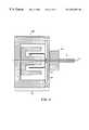
- FIG. 3shows an embodiment of the invention where the actuator is a DC servo motor and the needle housing, optical fiber, and motor, form an integrated unit.
- FIGS. 4A and 4Bshow embodiments of the invention where the needle is hollow and contains a movable optical fiber and beam director which may be advanced and retracted beyond the tip of the needle housing.
- FIG. 4Ais a cross-section of FIG. 4 B.
- FIG. 4Bshows a perspective view.
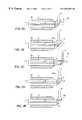
- FIGS. 5A-Dshow embodiments of the invention where the needle and optical fiber form a single, integrated unit and the needle and optical fiber move together.
- FIGS. 5A and 5Bshow an embodiment of the invention where the wall of the needle comprises an optical port and the beam director is in close juxtaposition to the optical port.
- FIG. 5Ais a cross-section of FIG. 5 B.
- FIG. 5Bshows a perspective view.
- FIGS. 5C and 5Dshow an embodiment of the invention where the housing of the needle has a variable diameter.
- FIG. 5Cis a cross-section of FIG. 5 D.
- FIG. 5Dshows a perspective view.
- FIG. 6shows an embodiment of the invention where the fiber optic needle probe is used in conjunction with an OCT imaging system.
- FIGS. 7A-Dshow embodiments where the fiber optic needle probe is used in internal body or intraluminal imaging applications.
- FIGS. 8A-8Cshow an embodiment of the invention where a solid tissue or organ is imaged using a stylette and a soft or semiflexible cannula with an integrated fiber optic needle probe in a multistep operation.
- FIGS. 9A and 9Bshow embodiments of the invention where the fiber optic needle probe comprises a two-channel needle assembly adapted for use as a fine needle aspiration excisional biopsy device.
- FIGS. 10A and 10Bshow embodiments of the invention where the fiber optic needle probe comprises a two-channel needle assembly adapted for use as a core needle excisional biopsy device.
- FIGS. 11A-Cshow an embodiment of the invention where the needle of the fiber optic needle probe comprises a coring tube within its bore and the optical fiber and beam director are positioned within the coring tube.
- FIGS. 11B and 11Cshow enlarged views of the tip and end of the needle distal to the tip, respectively.
- the inventioncomprises fiber optic needle probes for use with optical imaging systems to perform optical measurements of internal structures within a specimen.
- optical measurementsincludes both imaging and non-imaging measurement.
- fiber optic needle proberefers to a combination of a needle, an optical fiber, and a beam director.
- specimenas defined herein includes both biological and nonbiological specimens.
- Biological specimenstypically refer to solid structures in a living organism such as tissues or organs or the walls of vessels. Examples of tissues include, but are not limited to, neural tissue, subcutaneous fat, connective tissue, cartilage, and muscle.
- organswhich may be imaged include, but are not limited to, the heart, the liver, the lung, the brain, the kidneys, the ovaries, the prostate, the pancreas and skin. These specimens may be derived from humans, animals or plants. Nonbiological specimens include materials such mechanical assemblies or parts, and may include plastics, resins, polymers, composite materials, or the like.
- needle 5refers to a housing conformed in the shape of a needle for piercing and probing materials, tissues or organs. As shown in FIGS. 1A-D, for example, the needle 5 may comprise a pointed end or sharp edge so long as it is able to pierce a material, tissue or organ with minimal trauma or damage to the material, tissue or organ.
- the needle 5is constructed with a material which is rigid enough to be inserted into the desired material, tissue, or organ, but is also semiflexible and resistant to fracture.
- the needle 5is sized and shaped for nonintraluminal insertion into a material tissue or organ.
- nonintraluminal insertionrefers to insertion into a tissue, an organ, or through the wall of a vessel, which does not require insertion into an existing or created body opening or space.
- Preferred needle 5 materialsinclude, but are not limited to, metal, plastic, and other polymers.
- the needle 5is typically small in diameter (generally less than about 5 mm, and preferably less than about 200 ⁇ m) yet large enough to accommodate the smallest diameter optical fiber 11 which can be fabricated to guide a single optical mode.
- the needle 5is fabricated to have a variable diameter and/or variable stiffness. Varying the diameter of the needle 5 permits the fabrication and use of longer length needles 5 than would be possible with a fixed diameter, thus extending the range of internal structures which can be measured or imaged and the accessibility of these structures to measurement or imaging.
- the needle 5further comprises a handle assembly.
- the fiber optic needle probeis held in a manner similar to a pencil and inserted into the biological tissue or material that is to be imaged.
- the needle 5can be held by other means.
- the needle 5is mounted on a stereotactic frame which provides mechanical registration and precise positioning of the needle 5 relative to the object into which the fiber optic needle probe is being inserted.
- the needle 5is mounted on the frame of a microscope or other viewing device which provides a magnified image of the surface of the object into which the needle 5 is being inserted.
- the needle 5can also be inserted through the accessory port of a laparoscope and used for real-time imaging of solid organs during laparoscopic examination and surgery.
- the needle 5 housingwill be significantly longer than in the embodiment where the needle 5 is part of a hand-held probe.
- the fiber optic needle probeis provided with connecting cables for connection to a variety of imaging systems and/or other actuating means.
- the needlemay be constructed using a transparent or semitransparent material in order to emit an optical light beam 4 .
- Transparent materialsinclude plastic, glass, and other polymers.
- the needle 5comprises an optical port 7 .
- An optical port 7 as defined hereinis an opening which may be covered or uncovered, including, but not limited to, a window, slot, keyhole or a transparent section in the wall of the needle 5 .
- a transparent materialmay also cover the port 7 described above or span a section of the needle 5 such that it is integrated with the needle 5 . As shown in FIGS.
- the optical fiber 11emits light 4 through the optical port 7 ; and backscattered or backreflected 4 is received through the optical port 7 from the specimen being imaged.
- the optical port 7must be large enough to permit transmission of the light beam 4 from the beam director 6 as the fiber 11 is scanned over its desired range of positions.
- the optical port 7may define an opening at the end of the needle 5 or along the side of the needle 5 .
- the optical port 7may be configured in a variety of shapes including an oblong-shaped opening such as a slot.
- the major axis of the oblongmay be parallel or perpendicular to the longitudinal axis of the needle 5 .
- the optical port 7permits transmission of light 4 along a plurality of points substantially colinear with a longitudinal axis of the needle 5 .
- the optical port 7permits transmission of light 4 over a range of positions orthogonal to a longitudinal axis of the needle 5 .
- Other angular orientations of the oblong-shaped opening or slot with respect to the longitudinal axis of the needle 5are also envisioned and encompassed within the scope of the present invention.
- an optical fiber 11is positioned with a bore defined by the needle 5 .
- Optical fiber 11 materialsinclude glass, plastic, and other suitably optically transparent materials.
- the optical fiber 11is a single mode optical fiber 11 which emits and collects a single, or nearly single, transverse mode optical beam 4 at, or near, its distal end.
- the fiber 11consists of a core 2 , usually cylindrical in profile, of elevated index of refraction (e.g., glass) surrounded by a cladding 3 .
- the diameter of the core 2depends upon the wavelength of the light that it is designed to carry as well as the optical properties of the core 2 and the cladding 3 .
- the diameter of the core 2is generally in the range of 4 to 8 ⁇ m.
- the minimum diameter of the core 2is a few optical wavelengths.
- the cladding 3 of the fiber 11should have a diameter large enough such that the electric field of the optical beam 4 or mode which is present in the cladding 3 is not substantially perturbed by the outer boundary of the cladding 3 so as to introduce appreciable loss or dispersion, since the optical beam 4 or mode in the core 2 decays in an exponential manner in the cladding 3 as a function of the distance away from the core 2 .
- the cladding 3surrounds the core 2 of the fiber 11 and the typical cladding 3 diameter in a fiber 11 used for optical communications is ⁇ 125-200 microns. However, it is understood that while the aforementioned are typical dimensions of the cladding 3 , the cladding 3 can have a wide range of diameters and can be as small as 12-15 ⁇ m.
- optical fiber 11 diameterscan be constructed which carry single mode optical beams 4 .
- the smallest diameter cladding 3 for a single mode fiber 11depends upon the operating wavelength and details of the fiber 11 construction, but in preferred embodiments of the invention the diameter of the cladding 3 will be in the range of 15 to 20 ⁇ m.
- the optical fiber 11is provided with a coating or jacket 50 surrounding the cladding 3 , which can be a plastic, metal, polymer material, or the like.
- the jacket 50 of the fiber 11does not serve to guide the optical beam 4 but acts to protect the fiber 11 , strengthen it from breaking, and to increase its mechanical rigidity.
- the needle 5 casingitself may serve as the jacket 50 .
- the optical fiber 11is provided in close juxtaposition to a beam director 6 which serves to emit the optical beam 4 at an angle from the fiber 11 (usually approximately 90 degrees from the fiber 11 axis) to produce a focal spot of a desired spot size at a given distance from the fiber 11 .
- Two parametersmust be controlled by the beam director 6 : (1) the focal length of the lens or other optical element that is used to focus the beam 4 emitted from the fiber 11 , and (2) the effective distance of this lens or other optical element from the optical (mode) in the optical fiber 11 .
- Light 4 which is backscattered or backreflected from the specimenis also collected by beam director 6 and directed back into the fiber 11 .
- the beam director 6extends beyond the end of the needle 5 such that the optical beam 4 is transmitted around the end of the needle 5 .
- the beam director 6is positioned in close juxtaposition to the optical port 7 of the needle 5 such that it is capable of directing and receiving light beam 4 through the optical port 7 .
- an orienting elementis provided for maintaining the angular orientation of the fiber 11 and beam director 6 within the hollow needle 5 so that the beam 4 is transmitted in the desired direction.
- a “beam director” 6comprises optical element(s) provided at the distal end of the optical fiber 11 to deliver and to collect a single or nearly single transverse spatial mode optical beam 4 .
- Any combination of focusing and beam directing elements 6 known in the art which have appropriate parameters of focal length and sizemay be used.
- the optical element(s) of the beam director 6 encompassed by the inventioninclude, but are not limited to, a microprism, mirror (such as a fold mirror), lens, focusing element, and the like.
- the optical fiber 11includes an integrated lens at its tip and is in proximity to a right angle polished optically coated facet such that a focused optical beam 4 is emitted in a direction at an angle to the longitudinal axis of the fiber 11 .
- FIGS. 2A-Ddepict optical fibers 11 and beam directors 6 comprising different types of optical elements 6 A, 6 B, 6 C, and 6 D.
- FIGS. 2A-Bshow embodiments of the invention where beam director 6 is a ball lens.
- the ball lensis ground or polished and coated with a high-reflective coating such that the optical beam 4 is internally reflected from the planar angled facet 9 and directed through the curved surface 10 of the ball lens.
- the refractive power of the lensis determined by the ball lens material, the size of the ball lens or its radius of curvature, and the index of refraction of the material into which the beam 4 is launched and which is in contact with the lens.
- the ball lensmay be mounted directly on the end of the optical fiber 11 as shown in FIG. 2A (a section 6 A of the ball lens is shown) or used with a spacer which controls its distance from the end of the fiber 11 .
- the focal spot size and focal position of the beam 4may be controlled by changing the size of the ball lens and its spacing from the end of the fiber 11 .
- the end of the fiber 11may also be heat-treated in order to diffuse the boundary between the core 2 and cladding 3 region of the fiber 11 . This causes the optical beam 4 within the fiber 11 to become unguided, at which point the beam 4 begins to diffract.
- the position where the core 2 is diffused awayis controlled by controlling the point of application, temperature, and time of the heat treatment. This process is substantially equivalent to forming a spacer between the end of the fiber 11 and ball lens and is used as the second parameter in conjunction with the size of the ball lens to control the focused spot size and focal distance of the emitted beam 4 .
- FIG. 2Bshows a second embodiment of the invention in which the beam director 6 is a ball lens which has been fabricated directly onto the fiber 11 by controlled melting of the fiber 11 (a cross section 6 B is of this type of ball lens is shown in the Figure).
- Techniques for fabricating ball lensare well known in the art.
- the lensis ground and reflection-coated such that the optical beam 4 is directed at an angle from the fiber 11 axis and through the curved surface 10 of the lens.
- the effective position of the lensis controlled by heat-treating the end of the fiber 11 (at lower temperatures than those used to melt the fiber 11 and create the ball lens). The heattreating diffuses the boundary between the core 2 and cladding 3 of the fiber 11 .
- the processprovides an additional way to control the focused spot size and distance of the emitted beam.
- FIG. 2Cshows another embodiment of the invention in which a beam director 6 C is a graded index lens 12 with a microprism 13 on the end which is connected to the optical fiber 11 .
- the microprism 13deflects the beam 4 from the optical fiber 11 at an angle of approximately 90 degrees with respect to the longitudinal axis of the fiber optic needle probe.
- the angled facet forming the hypotenuse of the microprism 13is optically coated such that it is highly reflecting at the wavelength of the light 4 that is being used.
- the spot size of the focused beam 4 as well as the distance of the focus produced by this type of beam director 6is controlled by controlling design parameters including the focal length (pitch) of the graded index lens 12 , the spacing of the fiber 11 from the lens 12 , and the distance from the lens 12 to the tissue or specimen (controlled in part by the size of the microprism 13 ).
- the emitted beam 4is focused by varying the distance between the fiber 11 end and the lens 12 and filling the gap between the fiber 11 end and lens 12 with an optically transparent cement.
- the end of the fiber 11can also be heat-treated so that the boundary between the core 2 of the fiber 11 and the cladding 3 is diffused. This causes the core 2 of the fiber 11 to stop guiding the light 4 and the length of the fiber 11 treated behaves similarly to a spacer length.
- FIG. 2Dshows another embodiment of the invention in which the beam director 6 D is a microprism 13 connected to the optical fiber 11 such that the microprism 13 reflects the beam 4 emitted by the fiber 11 at an angle of approximately 90 degrees with respect to the longitudinal axis of the fiber 11 /needle 5 .
- a microlens 14is connected to a second surface of the microprism 13 where the beam 4 exits such that the beam 4 is focused into the specimen.
- the focal spot size of the beam 4 and the position of the focusis controlled by the focal length of the microlens 14 and the size of the microprism 13 .
- the microprism 13may not be a right angle prism and that the beam 4 may be deflected at an angle which differs from 90 degrees from the longitudinal axis of the needle.
- the microlens 14is shown integrally attached to the microprism 13 and is made as a single unit. In another embodiment of the invention, the microlens 14 and microprism 13 are adjacent, but separate elements.
- FIG. 2Eshows another embodiment of the invention in which the beam director 6 E is a focusing element 15 connected to an optical fiber 11 which performs focusing reflectively.
- the optical fiber 11is connected to a transparent element which has been formed into a reflective focusing element 15 such as an off-axis parabola.
- the reflective focusing element 15is formed by the outer surface of the transparent material and a highly reflective coating.
- the optical beam 4 emitted from the optical fiber 11begins to diverge at a designed distance from the reflective focusing element 15 . After reflection, the beam 4 is reflected at an angle from the longitudinal axis of the fiber 11 and focused.
- the optical beam 4is then emitted through a port 7 , such as a window, in the transparent element.
- the focal spot size of the beam 4 and the position of the focusis controlled by the orientation and curvature of the reflecting surface of the reflective focusing element and distance of the guiding section of the fiber 11 .
- a separate coreless fiberis attached between the optical fiber Hand the beam director 6 .
- the coreless fiberallows the optical beam 4 to expand prior to being focused by the beam director 6 .
- a coreless fiber with a length of ⁇ 800 ⁇ mwill expand the beam to ⁇ 40 ⁇ m.
- a lens radius of curvature of ⁇ 225 ⁇ mwill focus the light ⁇ 3 mm away to a spot of ⁇ 29 ⁇ m.
- the coreless fiberfacilitates larger exit beam apertures and thus longer focal lengths, working distances, and depth-of-field.
- Beam directors 6 similar to those shown in FIGS. 2A, 2 B, and 2 Dcan be formed by mass transport lens technology, reflow-technology, using surface tension of UV glue, mechanical grinding or polishing, acid etching, and the like.
- the fiber optic needle probeincludes an “end-fire” lens integral to a single-mode fiber 11 /coreless fiber unit.
- a separate 45-fold mirroris provided which is used to redirect light 4 directed from the fiber 11 /lens unit.
- the fold mirroris attached to a fiber 11 /lens unit. Methods of attachment include using heat shrink tubing or gluing the fiber 11 /lens unit to the needle 5 wall.
- the optical element(s) comprising the beam director 6will be shaped or covered with a shaped-structure so as to reduce contact of any sharp edges of the optical elements with the specimen, for example, a tissue. This serves the dual function of minimizing the drag on the needle 5 and also reduces trauma to the tissue as the needle 5 is moved.
- the distal optical elementsare shaped or covered with a shape having a sharp point to aid in insertion into the tissue or other type of specimen.
- an actuator 30is any device which can control the position and/or orientation of the optical fiber 11 , the needle 5 , or both the optical fiber 11 and the needle 5 .
- the actuator 30can include, but is not limited to, a motor (such as a stepping motor), a DC or AC electromagnetic motor, a galvanometer, a piezoelectric actuator, electro-static deflector, pneumatic motor, MEMs devices, or other mechanical device which can control motion.
- the actuator 30may be either at the front or the back of the handle assembly.
- the actuator 30 assemblyis initially separate from the needle 5 and fiber 11 such that the needle 5 is first introduced and the actuator 30 is attached to the fiber 11 and/or needle 5 .
- the actuator 30is detached from the needle 5 and motion of the needle 5 is directed via a torque cable or other mechanical linkage.
- position sensorsare coupled to the fiber 11 and/or needle 5 to provide information as to the position of the fiber 11 and/or needle 5 . This information is fed back to the control electronics of the actuators 30 which in turn adjust the position of the fiber 11 and/or needle 5 .
- the window or port 7contain fiducials, such as masks, which block the beam 4 from the optical fiber 11 , to allow feedback information to be obtained from the distal end of the optical fiber 11 .
- the movement of the beam director 6is also controlled by the actuator 30 .
- the optical fiber 11is actually attached to the beam director 6
- several different types of movementcan be controlled by the actuator 30 .
- the fiber 11 and the beam director 6may move as a unit independent of the needle 5 and housing and can be scanned in an axial or circumferential direction, or a combination of both.
- the fiber 11sits in the lumen of the needle 5 housing.
- the beam director 6is attached to the needle 5 housing and the housing is continuously spun or scanned back and forth circumferentially.
- a beam director 6such as a mirror, is moved independently of the optical fiber 11 .
- the actuator 30is attached directly to the housing.
- the actuator 30is directly attached to the optical fiber 11 .
- a simple DC servo motore.g., a speaker coil and position sensor
- the motorconsists of a magnet 16 and a coil 17 .
- the coil 17is housed on a flexure 18 to maintain proper registration and to allow smooth movement of the coil 17 in the axial direction and fixed registration in the lateral direction.
- the magnet 16 and coil 17have a small hollow center to allow the optical fiber 11 to thread through the center of the motor housing 19 , magnet, 16 and coil 17 into a modified needle housing portion 20 which includes at its distal end the piercing portion of the needle 5 .
- At least one of the magnet 16 and coil 17is capable of movement.
- At least one of the magnet 16 and coil 17is coupled to, or in mechanical communication with, the optical fiber 11 .
- the optical fiber 11can be secured to the magnet 16 or coil 17 using a variety of methods including simple epoxy.
- the modified needle housing portion 20forms part of a coring unit.
- actuator 30 /motor designsare also possible and included within the scope of the present invention.
- the motoris an offset motor with a mechanical pivot to multiply the stroke of the actuator 30 motor.
- a PZT motor or pneumatic actuator 30may also be used, as well as all of the actuator 30 motor methods listed above. It should be clear to one of ordinary skill in the art that a variety of actuators 30 and motors might be used and that these may be attached to any, or all of, the fiber 11 , beam director 6 , and needle 5 housing to effect the movement of these elements.
- the optical beam 4 scanning patternsdetermine the type of measurement or image that will be generated. There are three parameters which will be used herein to describe the position and direction of the beam 4 emitted from the distal end of the fiber 11 . These are defined with respect to the needle 5 axis.
- the coordinate oriented along the axis of the needle 5is defined as “z”.
- the beam emissionis scanned by varying the rotation of the optical fiber 11 and/or the needle 5 .
- the scanning motionmay be a continuous rotation of ⁇ which generates a cross sectional image in a planar circular region oriented perpendicular to the needle 5 axis.
- the scanningmay be a reciprocally varying (i.e., forward and back) rotation of angle which scans some portion of a circle and generates a cross sectional image in a planar sector region oriented perpendicular to the longitudinal axis of the needle 5 , the center of the said sector coincident with the needle 5 .
- the angle ⁇ of emission of the beam 4may not be 90 degrees from the needle 5 axis.
- the region which is scannedis a conical section or a sector like subset of a conical section.
- the beam 4is also scanned by varying the position of the beam 4 longitudinally (varying z). In this case the beam 4 position will be scanned in a reciprocal or periodic fashion (forward and back).
- the actuator 30 of FIG. 3i.e., motor comprising magnet 16 and coil 17 ) is particularly suitable for this scan motion.
- Varying zgenerates a planar cross sectional image containing the axis of the needle 5 .
- the orientation of the planeis determined by the orientation of the direction of the beam 4 (angle ⁇ ).
- the orientation of the image planeis controlled by rotating the fiber optic needle probe along its axis, varying the angle ⁇ .
- the angle ⁇ of emission of the beam 4is not 90 degrees from the needle 5 axis and the region which is imaged is described in terms of planar parallelogram which contains the axis of the needle 5 .
- orientations of the emitted beam 4 with ⁇ not equal to 90 degreesare preferred such as when it is desired to image a region ahead of the needle 5 .
- Another example where this orientation is desiredis for Doppler flow applications where the needle 5 is inserted through the wall of a tissue into an artery.
- Doppler flow measurementsit is necessary to have the emitted and collect optical beam 4 oriented such that it is partially along (i.e., has some vector component along) the direction of flow such that the backscattered or backreflected light 4 will have a Doppler frequency shift because of the flow.
- the position and orientation of the optical beam 4is scanned in both the longitudinal z and angular ⁇ directions.
- Thisprovides measurements or image information on multiple cross-sections or volumetric three-dimensional information.
- the scan patternis performed by scanning the angle ⁇ and changing the longitudinal position z incrementally. This is an angle priority scan and corresponds to performing imaging in a series of circular planer cross-sections at different longitudinal positions. If the angle ⁇ is not continuously scanned, but is scanned back and forth, this results in a imaging a series of sectors of circles at different longitudinal positions.
- the scan patternwill be performed by varying z rapidly (reciprocally) and varying ⁇ is a longitudinal priority scan corresponding to scanning a series of planes parallel to the axis of the needle 5 at different ⁇ angles.
- two parametersare scanned simultaneously.
- the scan patternmay be performed by varying ⁇ continuously and rapidly and varying z slowly, corresponding to a corkscrew image plane.
- the optical beam 4is scanned over a three-dimensional volume.
- no scanningwill be needed or desired. This, for example, would be the case in applications where a single parameter is measured or monitored over time. Changes of optical properties or flow (Doppler shift of the backscattered or backreflected light) are measured with the beam 4 along a single axis as other physical parameters in the tissue/specimen environment are varied.
- the cross-section being imagedis determined by a combination of the beam 4 scan geometry with the position and orientation of the fiber optic needle probe itself.
- the angular orientation and position of the tissue being imagedmay also be changed by rotating the fiber optic needle probe.
- the insertion (in the z direction) of the fiber optic needle probemay also be changed.
- the entire position and orientation of the needle 5may be controlled during the needle 5 insertion to guide it to the area of interest for imaging.
- the bore of the needle 5encases a movable optical fiber 11 .
- the inside diameter of the boreis large enough to permit free motion of the fiber 11 and beam director 6 along the z direction and ⁇ directions but not so large as to permit excessive wobble or position error of the fiber 11 .
- the z position and ⁇ angle of rotation of the fiber II and hence the z position and ⁇ angle of the emitted and collected optical beam 4are controlled by an actuator 30 or manual movement.
- position sensorsmay be coupled to the fiber 11 or the actuator 30 to provide information as to the position of the fiber 11 .
- position informationis fed back to control electronics of the actuator 30 to adjust the position of the optical fiber 11 .
- the optical fiber 11has sufficient rigidity so that z direction motion is actuated at the proximal end of the needle 5 with minimal backlash (see FIG. 1 A).
- This z axis motioncorresponds to alternately withdrawing and inserting the fiber 11 into the hollow needle 5 and results in a scanning of the z position of the emitted and collected optical beam 4 .
- the fiber optic needle probeproduces an image or measures the optical properties in a plane which contains axis of the fiber optic needle probe.
- the angular position ⁇ of the emitted optical beam 4and hence the angular orientation of the scanned plane may be controlled by rotating the entire fiber optic probe needle assembly.
- the angle of the beam 4 emissioncan be adjusted by using an index on the wall of the needle 5 or by the use of actuator(s) 30 .
- the rotation of the entire needle 5 /optical fiber 11 assemblymay also be done manually by the operator holding the handle of the fiber optic needle probe.
- rotationis performed by an actuator. Scanned angle ⁇ motion of the fiber 11 and beam director 6 combined with controlled actuated changes in position z may be used to generated a three-dimensional scan pattern.
- the optical fiber 11is actuated in the ⁇ direction corresponding to varying angle of the optical beam 4 emitted and collected by the beam director 6 attached to the fiber 11 .
- the fiber optic needle probewill produce an image or measure optical properties in a cross-sectional plane which is perpendicular to the longitudinal axis of the needle 5 .
- the rotation of the optical fiber 11is controlled by a mechanical actuator 30 at its proximal end. The rotational stiffness of the optical fiber 11 is large enough so that motion at the proximal end of the fiber 11 will be transmitted as a motion of the distal end of the fiber 11 .
- the angular rotation of the optical fiber 11is either continuous or reciprocal. Reciprocal angle scanning motion means that the angle of the beam 4 is scanned back and forth over a circle, or a subset of a circle, to generate a sector image.
- the z position of the emitted optical beam 4and hence the z position of the scanned plane, is also controlled by varying the insertion of the entire needle 5 /fiber 11 assembly in the specimen (e.g., tissue or organ).
- the insertion of the entire fiber optic needle probeis done manually by the operator holding the handle of the fiber optic needle probe.
- the z positionis varied by a mechanical actuator 30 .
- the fiber optic needle z probe positionwill be varied by retracting or pulling back the fiber optic needle probe.
- the scanned angle ⁇ motion of the fiber 11 and the distal optics of the beam director 6combined with controlled actuated changes in position z, is used to generate a three-dimensional scan pattern.
- the rotational stiffness of the optical fiber 11is sufficient so that motion at the proximal end will be transmitted as a motion of the distal end of the fiber 11 .
- torsionmay be generated in the fiber 11 so that the distal angle position leads or lags behind the proximal angle position.
- both the angle ⁇ and the position z of the fiber 11can be scanned simultaneously in an arbitrary pattern.
- meansare provided for transmitting the optical beam 4 emitted from the beam director 6 which conforms to this scan pattern.
- the needle 5is made from a transparent material, an arbitrary scan pattern can be implemented.
- the optical fiber 11 and beam director 6are housed in a modified hollow needle 21 , which functions as both an introducer and an enclosure.
- the introducer/enclosure 21permits the entire assembly to be inserted into a solid biological tissue such as an organ or through a tissue wall into the lumen of a hollow biological organ/vessel.
- the inner diameter of the introducer/enclosure 21is large enough to permit scanned motion of the fiber 11 .
- the central fiber 11 and beam director 6are advanced such that they protrude beyond the end of the introducer/enclosure 21 thus permitting the optical beam 4 to be directed into the tissue.
- the introducer/enclosure 21is retracted slightly as the fiber 11 and beam director 6 are held in place, resulting in a net motion of the end of the introducer/enclosure 21 backwards such that the beam director 6 is exposed.
- the beam director 6can thus be in full view of the tissue or other specimen that is being imaged.
- the preferred motion for scanning in this embodimentis scanning the fiber optic needle probe assembly such that the angle ⁇ of the beam 4 is varied.
- the introducer/enclosure 21covers part of the fiber 11 and reduces the friction that the tissue would have on the fiber 11 if it were in contact with the fiber 11 .
- the beam director 6 in this embodimentis not covered by the introducer/enclosure 21 so the optical beam 4 can be transmitted into the tissue or other specimen into which the introducer/enclosure 21 has been inserted.
- the area and volume of the distal optical elements comprising the beam director 6are small, the amount of resistance to motion or drag produced by these elements is small and does not appreciably impede the scanning motion.
- FIGS. 4A and 4Bshow the use of a prism as a beam director 6
- different implementations of beam directors 6may be used.
- a preferred implementation for a medical applicationwould be a covered beam director 6 or one having a rounded or smooth surface such that the trauma produced to the tissue from the scanning motion of the fiber 11 and distal optical elements of the beam director 6 would be minimized.
- the integrated fiber optic needle probe design shown in FIGS. 5A-Dpermits the actuation of the fiber 11 and beam director 6 by actuating the needle 5 itself, such that the needle 5 , fiber 11 , and beam director 6 move as a single, integrated unit (i.e., the fiber 11 is fixedly positioned within the needle 5 ).
- the needle 5moves relative to the tissue or other specimen into which it is inserted.
- the fiber 11 and beam director 6are actuated within a needle 5 or hollow tube and the needle 5 or hollow tube remains stationary with respect to the tissue or other specimen into which it is inserted.
- the preferred scanning pattern when the fiber 11 is fixedly positioned within the needle 5is scanning by rotating the fiber optic needle probe such that the angle ⁇ of optical beam 4 emission is varied.
- This scan motionmay be either continuous or reciprocal. Because the diameter of the needle 5 is small and its surface is smooth, the needle 5 may be rotated without significant friction or impediment to its motion. It is desirable that the distal end of the integrated fiber optic needle probe be as smooth as possible so that the rotary motion will not produce appreciable trauma to tissue. It is also recognized that the actuation or scanning of the integrated fiber optic needle probe is not restricted to angular motion and that other types of motion may be used depending on the particular application.
- the integrated fiber optic needle probemay be scanned with an angular motion either continuously or reciprocally and the entire needle 5 and fiber 11 assembly may be withdrawn or pulled back from the tissue.
- the entire needle 5 and fiber 11 assemblymay also be advanced into the tissue. This results in measurements or images being generated in a set of planes or nearly planer surfaces with varying longitudinal z positions.
- the integrated fiber optic needle probeis also scanned in the z direction.
- this scan patternresults in the measurements or images being performed in a plane which contains the longitudinal axis of the needle 5 .
- rotation of the needle 5 and fiber 11is used to select the angular orientation of the image plane.
- the needle 5 materialforms a jacket 50 around the optical fiber 11 .
- the fiber optic needleis fabricated by inserting a conventional or custom-specification single mode optical fiber 11 into a hollow metallic or plastic tube and shaped like a needle 5 bonding the metallic or plastic tube such that the tube and the fiber 11 form an integrated unit.
- the needle 5 materialmust have sufficient thickness such that it has sufficient rigidity to permit insertion, guidance, and manipulation of the needle 5 and is resistant to fracture. The thickness of the needle 5 material, in conjunction with the minimum diameter of the cladding 3 of the optical fiber 11 , will determine the minimum outer diameter of the integrated fiber optic needle device.
- the minimum thickness of the needle 5 material(and hence the thickness of the cladding 3 of the fiber 11 ) will depend strongly upon the properties of available materials and is expected to decrease if stronger, more flexible, materials are used for fabrication.
- the minimum thickness for the needle 5 materialwill be approximately 20 to 50 microns. This results in a minimum total outer diameter of the needle 5 of 100 to 200 microns.
- the integrated fiber optic needle probe designhas a number of advantages.
- One important advantage of the integrated, single-piece fiber 11 and 5 unitis that it permits the fabrication of a needle 5 with a smaller outer diameter than in the embodiment in which the needle 5 is a hollow tube and the fiber 11 and beam director 6 are actuated or scanned within the needle 5 .
- the integrated fiber optic needle probe embodimentsuch as shown in FIG. 5A, the single mode optical fiber 11 is contained within the needle 5 . If the beam director 6 is encased by the needle 5 , then means are provided for the optical beam 4 to be transmitted or passed through the needle 5 . This is shown schematically in FIG. 5 B.
- the optical beam 4is transmitted through an optical port 7 in the wall of the needle 5 and the beam director 6 is near, or at, the surface of the needle 5 .
- the fiber 11 and beam director 6need not be encased within the needle 5 but may extend beyond the distal end of the needle 5 bore as shown in FIGS. 4B, 5 C, and 5 D.
- the distal optical elements of the beam director 6are in direct contact with the tissue, specimen, or other material into which the optical beam 4 is directed.
- the integrated fiber optic needle probe designis also simpler than the two-piece fiber optic needle probe design in which the optical fiber 11 is actuated relative to the hollow needle 5 and hence may be less expensive to manufacture. Since this design does not require that the optical fiber 11 be actuated relative to a hollow needle 5 , the outer diameter of the integrated fiber optic needle probe may be made smaller than in the two-piece design because there is no need to have a clearance space between the needle 5 and the optical fiber 11 .
- the integrated fiber optic needle probemay have an extremely small outer diameter such that it may be inserted into living tissues internal to the body with minimal trauma. The small diameter of the integrated fiber optic needle probe permits it to be inserted through the walls of hollow organs or vessels and into the luminal spaces, or ducts, of these organs or vessels.
- the diameter of the needle 5is varied along its length such that a section 5 a of the needle 5 is larger in diameter than another section 5 b of the needle.
- This embodiment of the inventionprovides for increased rigidity at the wider section 5 a of the needle 5 .
- the fiber optical needle probecomprises a two-channel needle assembly (as shown in FIGS. 9A, 9 B, 10 A and 10 B, for example).
- the two-channel needle assemblycomprises a first housing and a second housing (details 43 and 44 , respectively, in FIGS. 9A and 9B, and details 49 and 50 , respectively, in FIGS. 10 A and 10 B).
- the first and second housingdefine a first and second channel, respectively.
- the term channel as used hereinrefers to a lumen within the housings.
- the optical fiber 11is substantially positioned within the channel of the second housing.
- the second housingmay be a rigid or semiflexible material, and is capable of emitting and collecting a single mode optical beam 4 .
- the second housing 44is in close juxtaposition to the first housing 43 and the entire assembly has a small enough diameter to allow it to be inserted as a unit directly into tissues or other specimens to permit nonintraluminal insertion into the tissue or specimen.
- the actuator 30is in communication with at least one of the first housing 43 , second housing 44 , optical fiber 11 , and beam director 6 , and is capable of moving at least one of the second housing, optical fiber 11 , and beam director 6 , so as to scan the internal structure of a specimen.
- the first housingcomprises an extracting device which may be a cutting device (for example, a sharp edge formed by the wall of the first housing itself or a movable cutter positioned within the lumen of the first housing) and the two-channel needle assembly is used as a biopsy needle with imaging capabilities.
- the extracting devicemay be an aspirating or pinching device.
- the fiber optic needle probeis designed for use in conjunction with any optical imaging engine which requires the controlled delivery and collection of a single spatial mode optical beam.
- the imaging engineincludes the associated sub-systems such as optics, electronics, motors, computers, and controls necessary to generate high resolution images, control image acquisition, or otherwise, process, quantitate, and display images.
- the fiber optic needle probe of the present inventioncan be integrated with OCT, it is also understood that cross-sectional images can be measured using any technique which is capable of performing a high resolution, high sensitivity measurement of the echo time delay, coherence properties, frequency properties, or other properties, of backreflected or backscattered light signals. These techniques include, but are not limited to, nonlinear cross-correlation techniques which measure the time variation and intensity of light.
- this inventioncan be applied with any optical measurement diagnostic technique (i.e., both imaging and nonimaging) which requires the delivery of a single transverse mode optical beam and the collection of reflected, remitted, or backscattered light in a single spatial optical mode where the position or orientation of the optical beam is scanned in a controlled pattern.
- imaging modalitiessuch as other interferometric and noninterferometric imaging systems, fluorescence and other spectroscopic imaging systems, Raman imaging, single photon confocal imaging, multiphoton confocal imaging systems, and combinations thereof.
- the fiber optic needle probemay be used in a nonimaging modality where it is desired to perform optical measurements of internal body structures on a microstructural scale, but where data may be represented in a form other than an image.
- FIG. 6shows a schematic containing the principle system modules in an OCT imaging system used with the fiber optic needle probe in a preferred embodiment of the invention.
- the systemincludes the fiber optic needle probe module which consists of a needle 5 , optical fiber 11 , and mechanical linkage 8 .
- Lightis coupled from an optical source 27 to the optical fiber 11 in the needle 5 and directed into the tissue or other specimen which is to be measured or imaged.
- An OCT measurement apparatus 28performs high sensitivity, high precision measurements of echo time delay (distance) and magnitude of the backscattered or backreflected light through the optical fiber 11 .
- the resulting datais recorded by a computer 29 , or alternatively, may be used to generate a video signal such as NTSC or PAL signal and the data directly displayed on a TV monitor.
- a mechanical actuator 30is attached to the optical fiber 11 and/or needle 5 and is used to scan the fiber 11 , or the needle 5 and the fiber 11 in the integrated fiber optic probe embodiment.
- the mechanical linkage 8provides a rotating optical coupling. This couples light from the rotating distal end of the optical fiber 11 connected to the needle 5 to the stationary proximal end of the fiber 11 connected to the measuring apparatus.
- the mechanical actuator 30which is connected to the fiber 11 is driven by a position- and scan-controller 31 in order to scan the optical beam 4 emitted by the fiber 11 optic needle probe in the desired pattern.
- the computer 29controls and/or measures the scan pattern of the optical beam 4 and measures the backreflected or backscattered signal profile as a function of the scan pattern.
- the computerprocesses this information and represents it as an image on a display module 32 .
- the imaging informationmay also be synthesized into a video NTSC or PAL) format and displayed on a screen or recorded on high resolution (SVHS or equivalent) video tape. Since in many cases the image resolution may be higher than standard video, digital video storage and display techniques may also be used.
- OCT imaging enginesThere are several different embodiments of OCT imaging engines including: (1) embodiments which use a low coherence light source and an interferometer in conjunction with methods which scan the group and phase delays of light in a reference arm or shift the frequency of light in a reference arm; (2) embodiments which use a low coherence source, an interferometer, and an optical spectrum analyzer to analyze the output spectrum of the interferometer; and (3) embodiments which use a narrow linewidth frequency tunable optical source and interferometer.
- non-interferometric methodsto measure the echo time delay of backscattered or backreflected light. It is also understood that the application of the fiber optic needle probe is not limited to OCT imaging.
- the OCT measurement module 28(or other measurement module), as well as the position and scan controller 31 , are controlled by a control computer module 29 which is responsible for synchronization, generating drive waveforms, generating necessary trigger pulses, storing and recalling data, and performing any necessary signal and image processing.
- the control computer module 29may also function as part of the display module 32 .
- the display module 32receives data from the computer module 29 and/or directly from the OCT measurement module 28 .
- Visualizationmay be performed with an OCT display module 32 (e.g., an image module) and/or a standard video monitor and/or a CRT.
- OCT display module 32e.g., an image module
- the OCT imagesmay be displayed simultaneously with, or merged with, other imaging modalities such as ultrasound or MRI to permit real-time guidance and placement of the fiber optic needle probe.
- other imaging modalitiessuch as ultrasound or MRI to permit real-time guidance and placement of the fiber optic needle probe.
- visualization techniqueswill permit other critical data to be analyzed, for example, permitting retrieval of previously acquired images and access to patient records while the procedure is being performed.
- OCT imagesare extremely high resolution and will typically exceed the resolution of conventional video, they may be stored in digital form.
- the operatorinserts the fiber optic needle probe into the tissue being imaged.
- the imaging processis ongoing during the insertion procedure, in which case this image information is used to guide the insertion of the fiber optic needle probe and its placement.
- fiber optic needle probe insertion and placementis guided using external features and landmarks of the body and known anatomy. Insertion and placement may also be guided based on data from other medical diagnostic modalities such as X-ray, computed tomography, ultrasound, magnetic resonance imaging, and the like.
- imagingincluding microscopic, laparoscopic, or endoscopic visualization; ultrasound, magnetic resonance imaging, radiography or computed tomography may be performed prior to, or in real-time, during the fiber optic needle probe insertion, to guide the fiber optic needle probe insertion and placement.
- the needle 5will be inserted into tissue or through tissue into a hollow sinus or intraluminal space.
- the fiber optic needle probewill be inserted from a position exterior to the body, e.g., through the skin, subcutaneous fat, and muscle layers into the body as the needle 5 is sized and shaped to permit nonintraluminal insertion.
- the fiber optic needle probeis also be inserted through a tissue from a position inside the lumen of a hollow organ or from an interior position in the body that may be exposed through an open field surgical procedure or laparoscopy.
- the upper limit on the length of the needle 5will be constrained by the need to guide the fiber optic needle probe during insertion and scan it during optical measurement (either nonimaging or imaging).
- the needle 5should be long enough for the distal end of the needle 5 to extend into a region of interest in the body upon insertion. If the fiber optic needle probe is inserted into tissue, through the skin, or through an organ barrier in order to obtain measurements or images of a solid tissue structure, then the length of the needle 5 may range from a few millimeters to as long as several centimeters. If the fiber optic needle probe is inserted through tissue into a hollow organ or lumen, then the length of the needle 5 may be longer than in the case where the fiber optic needle probe is inserted into a solid tissue without a lumen.
- the luminal spaceis used to guide the fiber optic needle probe to the point at which nonimaging measurements or imaging measurements are to be performed. Since the mechanical drag or friction on the needle 5 used in a luminal space is less than in the case where the fiber optic needle probe is inserted into a solid tissue, a longer needle 5 may be used in this scenario.
- the preferred length of the needle 5can be optimized to accommodate a specific application.
- the cross-section over which the fiber optic needle probe performs imagingis determined by the scanning pattern of the optical beam 4 that the fiber optic needle probe delivers and collects.
- the optical scan planemay be either along the longitudinal axis of the needle 5 or perpendicular to the longitudinal axis of the needle 5 .
- the scan patternmay also result in a surface of illumination which may take on a complex form such as cone, sector of a circle, helical surface, etc.
- the position and orientation of the optical scan planeis controlled by the motion of the optical fiber 11 and beam director 6 which deliver and collect the optical beam 4 .
- the optical fiber 11 and beam director 6are scanned relative to the hollow needle 5 housing.
- the position and/or orientation of the needle 5 itselfis scanned (the movement of the fiber 11 being dependent on the movement of the needle 5 ).
- the overall position of the fiber optic needle probeis optimized as the fiber optic needle probe is inserted, or manipulated, during imaging to determine the orientation of the cross-sectional planes as well as to select what structure will be imaged.
- FIGS. 7A-Dshow embodiments of the invention where the fiber optic needle probe is used for internal body imaging such as in medical applications.
- a fiber optic needle probeis inserted into a solid organ 34 and used to image the internal structure of the solid organ 34 .
- the organ structure which can be imaged safelywill depend on the diameter of the needle 5 and its sensitivity to trauma from the needle 5 insertion and manipulation. It is envisioned that different diameter and length needles 5 will be used depending on the application.
- the fiber optic needle probeis inserted into a space or sinus within the body and imaging is performed across the boundary of an organ into its interior (as shown in FIG. 7 B). In a further embodiment of the invention, imaging is performed across the boundary of a tumor for the purposes of localizing the border of the tumor.
- the fiber optic needle probeis inserted from an exterior or interior part of the body through intervening tissue 35 into a hollow organ or lumen structure 36 .
- Lumen structures 36may include blood vessels such as veins or arteries, or other luminal or ductal structures.
- the fiber optic needle probemay be used to perform cross-sectional imaging either perpendicular to the longitudinal axis of the needle 5 across the lumen structure 36 , or along the plane of the needle 5 across the lumen structure 36 . It is also understood that imaging may be performed by the fiber optic needle probe, for the process of inserting the fiber optic needle probe with the purpose of guiding said insertion.
- imagingis shown as being performed in a plane 37 containing the needle 5 in FIGS. 7A and 7C, and in a plane 38 perpendicular to the longitudinal axis of needle in FIGS. 7B and 7D.
- the image planes 37 and 38are shown as shaded regions in the Figures.
- the depth of the region which can be imagedis determined by the intensity of the light 4 which is emitted from the fiber optic needle probe, by the attenuation of the backreflected of backscattered light 4 which is collected by the fiber optic needle probe, by the sensitivity of the measurement apparatus, and by the desired rate of scanning and image acquisition time.
- Imaging depths in most biological tissuesare 2-3 mm, therefore image information can be obtained from cross-sectional planes of surfaces within a cylinder of approximately 4 to 6 mm diameter.
- Imaging parameters and the performance of the imaging systemare dependent on the details of the measurement apparatus as well as the properties of the tissue or specimen being measured or imaged, and should be optimized appropriately.
- an optical fiber 11is inserted into an object to be imaged with the aid of a stylette 40 and cannula 39 as shown in FIGS. 8A-C.
- This method of insertionentails providing a hollow tube which functions as a cannula 39 .
- the cannula 39has a wire stylette 40 or equivalent rigid structure inside which serves to increase the mechanical rigidity of the cannula 39 during the insertion process.
- the stylette 40may extend beyond the cannula 39 if the cannula 39 is open at the distal end and the stylette 40 may have a sharpened point to facilitate introduction into the tissue 41 .
- the cannula 39may also be closed at the distal end in which case the stylette 40 extends up to the distal end and is encased by the cannula 39 .
- the cannula 39is at least partially transparent.
- the stylette 40 and cannula 39are inserted or introduced together and guided such the distal end of the cannula 39 is in the structure which is to be measured or imaged. After insertion, the stylette 40 is withdrawn, leaving the hollow cannula 39 in place. As shown in FIG. 8C, an optical fiber 11 and beam director 6 is then inserted into the hollow cannula 39 .
- fiber 11 and beam director 6are inserted such that the beam director 6 emits and collects the optical beam 4 through the cannula 39 .
- This embodimenthas the advantage that the fiber 11 and beam director 6 may be scanned in an arbitrary pattern because there is no impediment to the transmission of the optical beam 4 into the tissue or specimen.
- the optical fiber 11 and beam director 6are inserted such that the beam director 6 extends beyond the end of the cannula 39 and thus emits the optical beam 4 directly into the tissue or specimen and collects the optical beam directly from the tissue or specimen.
- the cannula 39need not be made of a transparent material. This embodiment is similar to the hollow needle 5 introducer/enclosure embodiment shown in FIGS. 4A-B and discussed previously.
- the stylette 40 and cannula 39may be considered an extension of the hollow needle 5 introducer/enclosure where the hollow needle 5 introducer/enclosure (e.g., cannula 39 ) provides a hollow flexible sleeve which is itself introduced by the aid of a stylette 40 .
- the optical fiber 11 and beam director 6are mechanically actuated so that the optical beam 4 is scanned in the desired pattern.
- the cannula 39 or the actuator 30is already connected to the fiber 11 during the insertion process.
- the actuatoris attached by a clamp or chuck 42 to the fiber 11 after it is inserted, to make the insertion of the fiber 11 easier and more convenient.
- the stylette 40 and cannula 39are used in conjunction with an integrated fiber optic needle probe.
- the stylette 40 and cannula 39are inserted into a tissue or other specimen, the stylette 40 is withdrawn, and the integrated fiber optic needle probe is then inserted into the cannula 39 .
- the presence of the cannula 39serves to reduce the amount of drag or friction from the tissue or other specimen on the fiber optic needle probe when the probe is mechanically actuated.
- the cannula 39also serves to protect fiber optic needle probe from excessive bending or stress at the surface of the tissue or other specimen where such bending or stress may be more severe.
- image information from the fiber optic needle probe of the present inventionis used to guide and/or place a conventional excisional biopsy procedure.
- the fiber optic needle probemay be used in conjunction with, or integrated with, a standard biopsy instrument such as a fine needle aspirator, or core biopsy needle, to identify the position of the instrument with respect to the surrounding tissue structure.
- a standard biopsy instrumentsuch as a fine needle aspirator, or core biopsy needle
- Conventional excisional biopsy instrumentshave large diameters and the tissue removal process can produce significant tissue trauma. Unnecessary biopsies and sampling errors can be reduced by using the fiber optic needle probe to identify abnormal tissue or to avoid biopsy near sensitive structures such as blood vessels or nerves.
- the biopsy devicecan be used separately from the fiber optic needle probe or integrated together with the fiber optic needle probe.
- the biopsy devicemay pass over the fiber optic needle probe.
- the fiber optic needle probemay have an additional channel built into it which permits the aspiration of tissue from its distal end, as in the two-channel needle assembly embodiment.
- the fiber optic needle probecomprises a fine needle aspiration device.
- the fine needle aspiration deviceconsists of a hollow biopsy needle which is inserted into tissue and used to aspirate tissue into the needle by applying calibrated suction on the proximal end of the biopsy needle.
- the needle diameters used in a fine needle aspiration deviceare typically 1 mm and are typically larger than the diameter of the fiber optic needle probe. Because of this, the fiber optic needle probe may be configured as a fine needle aspiration biopsy device without significantly increasing its size or impairing its function.
- the purpose of providing a fiber optic needle probe imaging device comprising a needle biopsy deviceis to allow imaging of a tissue near a biopsy site.
- the fiber optic needle probeis provided as a two-channel needle assembly and consists of a first and second housing, 43 and 44 , defining a first and second channel, respectively.
- the first housing, or biopsy channel 43functions as a hollow needle for aspirating tissue
- the second housing, or optical fiber channel 44houses the optical fiber 11 and the distal optical element(s) which comprise the beam director 6 .
- the optical fiber 11is either inserted into the optical fiber channel 44 or is integrated directly into the second housing 44 .
- the beam director 6 of the fiber optic needle probemay extend beyond the distal tip of the two-channel needle assembly such that it can perform cross-sectional imaging at, or near, the end of the portion of the two-channel needle assembly used for aspirating tissue.
- FIGS. 10A and 10Bshow an embodiment of the invention in which the fiber optic needle probe comprises a coring biopsy device.
- the fiber optic needle probeis in the form of a two-channel needle assembly comprising a first housing configured as a core biopsy device 49 .
- the channel of the second housing, optical fiber housing 51can either extend the length of the first housing or can terminate near the section of first housing near a slot 47 which is used for obtaining the core tissue or biopsy specimen.
- the core biopsy device 49typically consists of a hollow outer casing 45 with an internal hollow tubular movable cutter 46 having a sharpened edge.
- the hollow outer casing 45typically has one or more slots 47 cut into it which permit the tissue specimen to be drawn or sucked into the hollow portion 48 of the outer casing. After the tissue specimen is drawn into the interior of the hollow outer casing 45 , the inner movable hollow tubular cutter 46 is advanced to cut a specimen or core of tissue. This core specimen is retained in the central part of the inner movable tubular cutter 46 .
- This design and related core biopsy designshave the advantage that they can be used to cut multiple tissue specimens or cores.
- the inner movable tubular cutter 46is retracted and advanced to cut a core specimen of tissue. The process may be repeated with each subsequent core specimen being held in the hollow inner movable tubular cutter 46 .
- the hollow inner movable tubular cutter 46is withdrawn and the tissue core specimens are extracted from the hollow inner cutter 46 by pushing them out with a solid wire or stylette. Alternately, the entire core needle biopsy device is withdrawn.
- the optical fiber 11is inserted into the second channel of the optical fiber housing 50 .
- the beam director 6 of the optical fiber 11extends beyond the end of the optical fiber housing 50 to permit the optical beam 4 to be directed and scanned into the tissue and to collect backreflected or backscattered optical signals from the tissue as shown in FIG. 10 A.
- an opening 52is provided in the optical fiber housing 50 which permits the optical beam 4 to be directed and scanned into the tissue as shown in FIG. 10 B.
- the fiber optic needle probeperforms cross-sectional imaging or takes other optical measurements of the internal microstructure of the tissue into which the two-channel needle assembly is inserted. These images or other optical measurement information can serve to guide the placement of the two-channel needle assembly to avoid injury to sensitive structures and allow the physician to determine the areas of tissue which should be biopsied.
- FIGS. 11A-Cshow an embodiment of the invention in which the fiber optical needle probe comprises a core biopsy needle 54 comprising a coring tube 53 and a needle assembly 55 comprising a cone-shaped tip 55 t.
- a biopsy opening 56is provided at the cone-shaped 55 t and an actuator, in this example, a motor 57 , is provided in proximity to the coring tube 53 .
- FIG. 11Bshows an enlarged view of a cut-away of the cone-shaped tip 55 t.
- the coring tube 53extends substantially through the lumen 58 of the core biopsy needle 54 housing.
- the optical fiber 11is positioned substantially within, or adjacent, the lumen 59 of the coring tube 53 .
- Two optical elementscomprise the beam director 6 in this embodiment.
- the optical fiber 11itself comprises an integral lens 6 F which is in optical communication with a 45 degree turning mirror 6 G.
- FIG. 11Cshows an enlarged view of the coring tube 53 and motor 57 .
- the coring tube 53 housingcomprises a lure 60 which fits securely into the lure of an enlarged portion 61 of core biopsy needle housing 54 .
- the flat parts of the lure 60ensure proper registration of the coring tube 53 and needle assembly 55 .
- Other arrangements, such as a bayonet or screw fitting,are also encompassed within the scope of the present invention.
- the coring tube 53 assembly and the needle assembly 55can be integrated or part of separate devices.
Landscapes
- Health & Medical Sciences (AREA)
- Physics & Mathematics (AREA)
- Life Sciences & Earth Sciences (AREA)
- Optics & Photonics (AREA)
- General Health & Medical Sciences (AREA)
- Engineering & Computer Science (AREA)
- Surgery (AREA)
- Pathology (AREA)
- General Physics & Mathematics (AREA)
- Molecular Biology (AREA)
- Medical Informatics (AREA)
- Biophysics (AREA)
- Biomedical Technology (AREA)
- Heart & Thoracic Surgery (AREA)
- Animal Behavior & Ethology (AREA)
- Public Health (AREA)
- Veterinary Medicine (AREA)
- Radiology & Medical Imaging (AREA)
- Nuclear Medicine, Radiotherapy & Molecular Imaging (AREA)
- Chemical & Material Sciences (AREA)
- Nanotechnology (AREA)
- Spectroscopy & Molecular Physics (AREA)
- Biochemistry (AREA)
- Immunology (AREA)
- Dermatology (AREA)
- Crystallography & Structural Chemistry (AREA)
- Analytical Chemistry (AREA)
- Investigating Or Analysing Materials By Optical Means (AREA)
Abstract
Description
Claims (22)
Priority Applications (2)
| Application Number | Priority Date | Filing Date | Title |
|---|---|---|---|
| US09/359,574US6564087B1 (en) | 1991-04-29 | 1999-07-22 | Fiber optic needle probes for optical coherence tomography imaging |
| PCT/US2000/001228WO2000042906A2 (en) | 1999-01-22 | 2000-01-19 | Fiber optic needle probes for optical coherence tomography imaging |
Applications Claiming Priority (9)
| Application Number | Priority Date | Filing Date | Title |
|---|---|---|---|
| US69287791A | 1991-04-29 | 1991-04-29 | |
| US08/033,194US5459570A (en) | 1991-04-29 | 1993-03-16 | Method and apparatus for performing optical measurements |
| US25294094A | 1994-06-02 | 1994-06-02 | |
| US49273895A | 1995-06-21 | 1995-06-21 | |
| US08/577,366US5748598A (en) | 1995-12-22 | 1995-12-22 | Apparatus and methods for reading multilayer storage media using short coherence length sources |
| US08/607,787US6134003A (en) | 1991-04-29 | 1996-02-27 | Method and apparatus for performing optical measurements using a fiber optic imaging guidewire, catheter or endoscope |
| US08/916,759US5784352A (en) | 1995-07-21 | 1997-08-19 | Apparatus and method for accessing data on multilayered optical media |
| US11685999P | 1999-01-22 | 1999-01-22 | |
| US09/359,574US6564087B1 (en) | 1991-04-29 | 1999-07-22 | Fiber optic needle probes for optical coherence tomography imaging |
Related Parent Applications (1)
| Application Number | Title | Priority Date | Filing Date |
|---|---|---|---|
| US08/916,759Continuation-In-PartUS5784352A (en) | 1991-04-29 | 1997-08-19 | Apparatus and method for accessing data on multilayered optical media |
Publications (1)
| Publication Number | Publication Date |
|---|---|
| US6564087B1true US6564087B1 (en) | 2003-05-13 |
Family
ID=26814693
Family Applications (1)
| Application Number | Title | Priority Date | Filing Date |
|---|---|---|---|
| US09/359,574Expired - Fee RelatedUS6564087B1 (en) | 1991-04-29 | 1999-07-22 | Fiber optic needle probes for optical coherence tomography imaging |
Country Status (2)
| Country | Link |
|---|---|
| US (1) | US6564087B1 (en) |
| WO (1) | WO2000042906A2 (en) |
Cited By (474)
| Publication number | Priority date | Publication date | Assignee | Title |
|---|---|---|---|---|
| US20020019644A1 (en)* | 1999-07-12 | 2002-02-14 | Hastings Roger N. | Magnetically guided atherectomy |
| US20020065469A1 (en)* | 2000-08-31 | 2002-05-30 | Hsu Pei-Feng | Optical imaging using the temporal direct reflective signal from a minimized pulse width laser |
| US20020080096A1 (en)* | 2000-12-08 | 2002-06-27 | The University Of Tokyo | Image displaying method and an image display |
| US20020183625A1 (en)* | 1999-02-01 | 2002-12-05 | Scimed Life Systems, Inc. | Medical scanning system and related method of scanning |
| US20020198457A1 (en)* | 2001-04-30 | 2002-12-26 | Tearney Guillermo J. | Method and apparatus for improving image clarity and sensitivity in optical coherence tomography using dynamic feedback to control focal properties and coherence gating |
| US20030100836A1 (en)* | 2001-11-29 | 2003-05-29 | The Regents Of The University Of California | Optical probe with reference fiber |
| US20030135101A1 (en)* | 2001-12-21 | 2003-07-17 | Advanced Cardiovascular Systems, Inc. | System and methods for imaging within a body lumen |
| US20040010204A1 (en)* | 2002-03-28 | 2004-01-15 | Pearl Technology Holdings, Llc | Electronic/fiberoptic tissue differentiation instrumentation |
| US20040017961A1 (en)* | 2002-07-25 | 2004-01-29 | Petersen Christopher L. | Scanning miniature optical probes with optical distortion correction and rotational control |
| US20040092829A1 (en)* | 2002-11-07 | 2004-05-13 | Simon Furnish | Spectroscope with modified field-of-view |
| US20040111032A1 (en)* | 2002-12-04 | 2004-06-10 | Jeff Korn | Optical coupler for rotating catheter |
| US20040162487A1 (en)* | 2002-11-29 | 2004-08-19 | Klaus Klingenbeck-Regn | Medical examination and/or treatment system |
| US20050004453A1 (en)* | 2003-01-24 | 2005-01-06 | Tearney Guillermo J. | System and method for identifying tissue using low-coherence interferometry |
| US20050018201A1 (en)* | 2002-01-24 | 2005-01-27 | De Boer Johannes F | Apparatus and method for ranging and noise reduction of low coherence interferometry lci and optical coherence tomography oct signals by parallel detection of spectral bands |
| US20050018200A1 (en)* | 2002-01-11 | 2005-01-27 | Guillermo Tearney J. | Apparatus for low coherence ranging |
| US20050027199A1 (en)* | 2001-04-11 | 2005-02-03 | Clarke Dana S. | Tissue structure identification in advance of instrument |
| US20050035295A1 (en)* | 2003-06-06 | 2005-02-17 | Brett Bouma | Process and apparatus for a wavelength tuning source |
| US6904197B2 (en)* | 2002-03-04 | 2005-06-07 | Corning Incorporated | Beam bending apparatus and method of manufacture |
| US20050128488A1 (en)* | 2003-11-28 | 2005-06-16 | Dvir Yelin | Method and apparatus for three-dimensional spectrally encoded imaging |
| US20050140987A1 (en)* | 2003-05-01 | 2005-06-30 | University Of Florida Research Foundation, Inc. | Vertical displacement device |
| US20050143664A1 (en)* | 2003-10-09 | 2005-06-30 | Zhongping Chen | Scanning probe using MEMS micromotor for endosocopic imaging |
| US20050165315A1 (en)* | 2004-01-27 | 2005-07-28 | Infraredx, Inc. | Side firing fiber optic array probe |
| US20050168735A1 (en)* | 2003-01-24 | 2005-08-04 | Boppart Stephen A. | Nonlinear interferometric vibrational imaging |
| US20050171433A1 (en)* | 2004-01-08 | 2005-08-04 | Boppart Stephen A. | Multi-functional plasmon-resonant contrast agents for optical coherence tomography |
| WO2005085750A1 (en)* | 2004-03-04 | 2005-09-15 | Carl Mahr Holding Gmbh | Optical measuring head |
| US20050254061A1 (en)* | 2004-05-14 | 2005-11-17 | Alphonse Gerard A | Low coherence interferometry for detecting and characterizing plaques |
| US20050254060A1 (en)* | 2004-05-14 | 2005-11-17 | Alphonse Gerard A | Low coherence interferometry for detecting and characterizing plaques |
| US20050254059A1 (en)* | 2004-05-14 | 2005-11-17 | Alphonse Gerard A | Low coherence interferometric system for optical metrology |
| US20050267340A1 (en)* | 2004-03-29 | 2005-12-01 | Olympus Corporation | In-vivo information measurement apparatus |
| EP1602899A1 (en)* | 2004-06-01 | 2005-12-07 | Schleifring und Apparatebau GmbH | Fiber optic sensor |
| US20050280828A1 (en)* | 2001-10-16 | 2005-12-22 | The General Hospital Corporation | Systems and methods for imaging a sample |
| US20060013544A1 (en)* | 2004-07-02 | 2006-01-19 | Bouma Brett E | Imaging system and related techniques |
| WO2005072597A3 (en)* | 2003-12-31 | 2006-02-16 | Mauna Kea Technologies | Integrated scanning miniature optical head for producing a homogeneous confocal image, and confocal imaging system using same |
| US20060055936A1 (en)* | 2004-09-10 | 2006-03-16 | The General Hospital Corporation | System and method for optical coherence imaging |
| US20060067620A1 (en)* | 2004-09-29 | 2006-03-30 | The General Hospital Corporation | System and method for optical coherence imaging |
| US20060072874A1 (en)* | 2004-10-01 | 2006-04-06 | University Of Washington | Configuration memory for a scanning beam device |
| US20060095065A1 (en)* | 2004-09-24 | 2006-05-04 | Tetsuaki Tanimura | Fluid occluding devices and methods |
| US20060093276A1 (en)* | 2004-11-02 | 2006-05-04 | The General Hospital Corporation | Fiber-optic rotational device, optical system and method for imaging a sample |
| US20060132790A1 (en)* | 2003-02-20 | 2006-06-22 | Applied Science Innovations, Inc. | Optical coherence tomography with 3d coherence scanning |
| US20060138238A1 (en)* | 2004-12-23 | 2006-06-29 | University Of Washington | Methods of driving a scanning beam device to achieve high frame rates |
| WO2006095343A1 (en) | 2005-03-10 | 2006-09-14 | Anatoly Babchenko | An optical sensor and a method of its use |
| US20060212099A1 (en)* | 2005-03-15 | 2006-09-21 | Riddell Robert H | Optical skin germicidal device and method |
| US20060226231A1 (en)* | 2005-03-29 | 2006-10-12 | University Of Washington | Methods and systems for creating sequential color images |
| US20060241503A1 (en)* | 2005-02-10 | 2006-10-26 | Lightlab Imaging, Inc. | Optical coherence tomography apparatus and methods |
| US20060244973A1 (en)* | 2003-10-27 | 2006-11-02 | Seok-Hyun Yun | Method and apparatus for performing optical imaging using frequency-domain interferometry |
| US20060270929A1 (en)* | 2005-05-31 | 2006-11-30 | The General Hospital Corporation | System, method and arrangement which can use spectral encoding heterodyne interferometry techniques for imaging |
| US20060285635A1 (en)* | 2005-04-15 | 2006-12-21 | Boppart Stephen A | Contrast enhanced spectroscopic optical coherence tomography |
| US20060293644A1 (en)* | 2005-06-21 | 2006-12-28 | Donald Umstadter | System and methods for laser-generated ionizing radiation |
| US20070019906A1 (en)* | 2005-07-21 | 2007-01-25 | University Of Washington Uw Tech Transfer - Invention Licensing | Methods and systems for counterbalancing a scanning beam device |
| WO2007018494A1 (en)* | 2005-07-21 | 2007-02-15 | University Of Washington | Methods and systems for counterbalancing a scanning beam device |
| US7184148B2 (en) | 2004-05-14 | 2007-02-27 | Medeikon Corporation | Low coherence interferometry utilizing phase |
| US20070055117A1 (en)* | 2004-05-14 | 2007-03-08 | Alphonse Gerard A | Low coherence interferometry utilizing phase |
| US7189961B2 (en) | 2005-02-23 | 2007-03-13 | University Of Washington | Scanning beam device with detector assembly |
| US20070073162A1 (en)* | 2000-10-30 | 2007-03-29 | The General Hospital Corporation | Methods and systems for tissue analysis |
| EP1769734A1 (en)* | 2005-09-30 | 2007-04-04 | FUJIFILM Corporation | Optical probe for obtaining a tomographic image |
| US20070087445A1 (en)* | 2005-10-14 | 2007-04-19 | The General Hospital Corporation | Arrangements and methods for facilitating photoluminescence imaging |
| US20070133002A1 (en)* | 2005-10-11 | 2007-06-14 | Duke University | Systems and methods for endoscopic angle-resolved low coherence interferometry |
| EP1770354A3 (en)* | 2005-09-30 | 2007-07-11 | FUJIFILM Corporation | Optical probe and optical tomography system |
| US20070171430A1 (en)* | 2006-01-20 | 2007-07-26 | The General Hospital Corporation | Systems and methods for providing mirror tunnel micropscopy |
| US20070191733A1 (en)* | 2006-01-20 | 2007-08-16 | The Regents Of The University Of Michigan | In Situ Tissue Analysis Device and Method |
| US20070223006A1 (en)* | 2006-01-19 | 2007-09-27 | The General Hospital Corporation | Systems and methods for performing rapid fluorescence lifetime, excitation and emission spectral measurements |
| US20070233396A1 (en)* | 2005-09-29 | 2007-10-04 | The General Hospital Corporation | Method and apparatus for optical imaging via spectral encoding |
| US20070236700A1 (en)* | 2006-04-05 | 2007-10-11 | The General Hospital Corporation | Methods, arrangements and systems for polarization-sensitive optical frequency domain imaging of a sample |
| US20070239033A1 (en)* | 2006-03-17 | 2007-10-11 | The General Hospital Corporation | Arrangement, method and computer-accessible medium for identifying characteristics of at least a portion of a blood vessel contained within a tissue using spectral domain low coherence interferometry |
| US20070244357A1 (en)* | 2006-04-17 | 2007-10-18 | Wiklof Christopher A | Scanned beam imagers and endoscopes utilizing multiple light collectors |
| US20070244365A1 (en)* | 2006-04-17 | 2007-10-18 | Microvision, Inc. | Scanned beam imagers and endoscopes with positionable light collector |
| US20070260198A1 (en)* | 2003-04-25 | 2007-11-08 | Lightlab Imaging, Llc | Flush catheter with flow directing sheath |
| US20070263227A1 (en)* | 2006-05-12 | 2007-11-15 | The General Hospital Corporation | Processes, arrangements and systems for providing a fiber layer thickness map based on optical coherence tomography images |
| US20070274650A1 (en)* | 2006-02-01 | 2007-11-29 | The General Hospital Corporation | Apparatus for controlling at least one of at least two sections of at least one fiber |
| US20070278389A1 (en)* | 2006-06-02 | 2007-12-06 | Mahesh Ajgaonkar | Multi-channel low coherence interferometer |
| US7312879B2 (en) | 2005-08-23 | 2007-12-25 | University Of Washington | Distance determination in a scanned beam image capture device |
| US20070299309A1 (en)* | 2005-02-28 | 2007-12-27 | University Of Washington | Monitoring disposition of tethered capsule endoscope in esophagus |
| US20080007734A1 (en)* | 2004-10-29 | 2008-01-10 | The General Hospital Corporation | System and method for providing Jones matrix-based analysis to determine non-depolarizing polarization parameters using polarization-sensitive optical coherence tomography |
| US20080013900A1 (en)* | 2005-01-21 | 2008-01-17 | Optiscan Pty Ltd. | Fiber bundle for contact endomicroscopy |
| US20080021276A1 (en)* | 2006-07-21 | 2008-01-24 | Oncoscope, Inc. | Protective probe tip, particularly for use on a fiber-optic probe used in an endoscopic application |
| US7327463B2 (en) | 2004-05-14 | 2008-02-05 | Medrikon Corporation | Low coherence interferometry utilizing magnitude |
| US20080058629A1 (en)* | 2006-08-21 | 2008-03-06 | University Of Washington | Optical fiber scope with both non-resonant illumination and resonant collection/imaging for multiple modes of operation |
| US20080084565A1 (en)* | 2006-10-05 | 2008-04-10 | General Electric Company | Interferometer-based real time early fouling detection system and method |
| US20080132834A1 (en)* | 2006-12-04 | 2008-06-05 | University Of Washington | Flexible endoscope tip bending mechanism using optical fibers as tension members |
| WO2008068685A1 (en)* | 2006-12-06 | 2008-06-12 | Koninklijke Philips Electronics N.V. | Obtaining optical tissue properties |
| US20080161696A1 (en)* | 2006-11-08 | 2008-07-03 | Lightlab Imaging, Inc. | Opto-acoustic imaging devices and methods |
| US20080165366A1 (en)* | 2007-01-10 | 2008-07-10 | Lightlab Imaging, Inc. | Methods and apparatus for swept-source optical coherence tomography |
| WO2008092791A1 (en)* | 2007-01-31 | 2008-08-07 | Sirona Dental Systems Gmbh | Apparatus and method for optical 3d measurement |
| US20080194969A1 (en)* | 2005-04-29 | 2008-08-14 | The Regents Of The University Of Colorado | Multi-Excitation Diagnostic System and Methods for Classification of Tissue |
| US20080206804A1 (en)* | 2007-01-19 | 2008-08-28 | The General Hospital Corporation | Arrangements and methods for multidimensional multiplexed luminescence imaging and diagnosis |
| US20080221388A1 (en)* | 2007-03-09 | 2008-09-11 | University Of Washington | Side viewing optical fiber endoscope |
| US20080234586A1 (en)* | 2007-03-19 | 2008-09-25 | The General Hospital Corporation | System and method for providing noninvasive diagnosis of compartment syndrome using exemplary laser speckle imaging procedure |
| US20080243030A1 (en)* | 2007-04-02 | 2008-10-02 | University Of Washington | Multifunction cannula tools |
| US20080247714A1 (en)* | 2007-04-03 | 2008-10-09 | Mamoru Nakamura | Optical fiber/glass tube fusion-spliced structure, optical fiber assembly including the structure and glass tube used in the structure |
| WO2008137710A1 (en)* | 2007-05-03 | 2008-11-13 | University Of Washington | High resolution optical coherence tomography based imaging for intraluminal and interstitial use implemented with a reduced form factor |
| US20090024191A1 (en)* | 2006-03-03 | 2009-01-22 | University Of Washington | Multi-cladding optical fiber scanner |
| DE102007039556B3 (en)* | 2007-08-22 | 2009-01-22 | Carl Mahr Holding Gmbh | Optical microprobe |
| US20090030317A1 (en)* | 2007-07-25 | 2009-01-29 | Mayo Foundation For Medical Education And Research | Ultrasonic imaging devices, systems, and methods |
| US20090046980A1 (en)* | 2007-08-15 | 2009-02-19 | Rohlen Brooks H | System and method for positioning a probe |
| US20090052849A1 (en)* | 2007-08-22 | 2009-02-26 | Gwangju Institute Of Science And Technology | Optical fiber probe for side imaging and method of manufacturing the same |
| US20090069673A1 (en)* | 2007-03-16 | 2009-03-12 | The Charles Stark Draper Laboratory, Inc. | Spinal needle optical sensor |
| US20090073456A1 (en)* | 2007-09-13 | 2009-03-19 | Duke University | Apparatuses, systems, and methods for low-coherence interferometry (lci) |
| US20090103792A1 (en)* | 2007-10-22 | 2009-04-23 | Visiongate, Inc. | Depth of Field Extension for Optical Tomography |
| US7530987B1 (en)* | 2002-04-24 | 2009-05-12 | Cardica, Inc. | Surgical tool for creating an incision in a tubular vessel |
| US20090122320A1 (en)* | 2007-11-12 | 2009-05-14 | Lightlab Imaging, Inc. | Imaging catheter with integrated reference reflector |
| US20090131801A1 (en)* | 2007-10-12 | 2009-05-21 | The General Hospital Corporation | Systems and processes for optical imaging of luminal anatomic structures |
| US7538859B2 (en) | 2006-02-01 | 2009-05-26 | The General Hospital Corporation | Methods and systems for monitoring and obtaining information of at least one portion of a sample using conformal laser therapy procedures, and providing electromagnetic radiation thereto |
| EP1722669A4 (en)* | 2004-02-27 | 2009-05-27 | Optiscan Pty Ltd | Optical element |
| US20090137893A1 (en)* | 2007-11-27 | 2009-05-28 | University Of Washington | Adding imaging capability to distal tips of medical tools, catheters, and conduits |
| US20090177094A1 (en)* | 2008-01-08 | 2009-07-09 | Oncoscope, Inc. | Systems and methods for tissue examination, diagnostic, treatment, and/or monitoring |
| US20090182315A1 (en)* | 2007-12-07 | 2009-07-16 | Ceramoptec Industries Inc. | Laser liposuction system and method |
| US7567349B2 (en) | 2003-03-31 | 2009-07-28 | The General Hospital Corporation | Speckle reduction in optical coherence tomography by path length encoded angular compounding |
| US20090192358A1 (en)* | 2008-01-28 | 2009-07-30 | The General Hospital Corporation | Systems, processes and computer-accessible medium for providing hybrid flourescence and optical coherence tomography imaging |
| US20090213387A1 (en)* | 2008-02-25 | 2009-08-27 | Fujifilm Corporation | Optical probe and optical tomographic image production apparatus using the probe |
| US20090221920A1 (en)* | 2008-01-18 | 2009-09-03 | Boppart Stephen A | Low-coherence interferometry and optical coherence tomography for image-guided surgical treatment of solid tumors |
| US7586618B2 (en) | 2005-02-28 | 2009-09-08 | The Board Of Trustees Of The University Of Illinois | Distinguishing non-resonant four-wave-mixing noise in coherent stokes and anti-stokes Raman scattering |
| WO2009109873A1 (en)* | 2008-03-03 | 2009-09-11 | Koninklijke Philips Electronics N.V. | Biopsy guidance by image-based x-ray guidance system and photonic needle |
| US20090235396A1 (en)* | 2000-06-19 | 2009-09-17 | University Of Washington | Integrated optical scanning image acquisition and display |
| DE102008013859A1 (en)* | 2008-03-12 | 2009-09-24 | Siemens Aktiengesellschaft | Catheter for use in medical examining and treating device, for treating tachycardia of heart during minimally invasive surgery, has flexible sleeve surrounding catheter cavity, and sensor arranged in area of catheter tip |
| WO2009094341A3 (en)* | 2008-01-21 | 2009-10-01 | The Regents Of The University Of California | Endovascular optical coherence tomography device |
| US20090306520A1 (en)* | 2008-06-02 | 2009-12-10 | Lightlab Imaging, Inc. | Quantitative methods for obtaining tissue characteristics from optical coherence tomography images |
| WO2009109879A3 (en)* | 2008-03-03 | 2009-12-23 | Koninklijke Philips Electronics N.V. | Biopsy guidance by electromagnetic tracking and photonic needle |
| US20090326525A1 (en)* | 2008-06-26 | 2009-12-31 | Jessica Hixon | Laser fiber capillary apparatus and method |
| US7643153B2 (en) | 2003-01-24 | 2010-01-05 | The General Hospital Corporation | Apparatus and method for ranging and noise reduction of low coherence interferometry LCI and optical coherence tomography OCT signals by parallel detection of spectral bands |
| US20100094168A1 (en)* | 2007-03-23 | 2010-04-15 | Siegfried Riek | Instrument for the medical examination of tight body ducts |
| US20100094127A1 (en)* | 2008-10-14 | 2010-04-15 | Lightlab Imaging, Inc. | Methods for stent strut detection and related measurement and display using optical coherence tomography |
| WO2010046836A1 (en)* | 2008-10-22 | 2010-04-29 | Koninklijke Philips Electronics N.V. | An optical scanning probe assembly |
| US20100123903A1 (en)* | 2008-11-19 | 2010-05-20 | Industrial Technology Research Institute | Optical scanning probe |
| WO2010075368A1 (en)* | 2008-12-22 | 2010-07-01 | Ams Research Corporation | Side-firing optic fiber tip with length-based beam diameter |
| US7751057B2 (en) | 2008-01-18 | 2010-07-06 | The Board Of Trustees Of The University Of Illinois | Magnetomotive optical coherence tomography |
| US20100191057A1 (en)* | 2008-07-28 | 2010-07-29 | Jansen Lex P | Penetrating member with direct visualization |
| US20100207015A1 (en)* | 2007-07-20 | 2010-08-19 | Koninklijke Philips Electronics N.V. | Fiber-optic scanner |
| US7784697B2 (en) | 2004-12-23 | 2010-08-31 | University Of Washington | Methods of driving a scanning beam device to achieve high frame rates |
| US7787129B2 (en) | 2006-01-31 | 2010-08-31 | The Board Of Trustees Of The University Of Illinois | Method and apparatus for measurement of optical properties in tissue |
| US20100228124A1 (en)* | 2009-03-08 | 2010-09-09 | Jeffrey Brennan | Medical and veterinary imaging and diagnostic procedures utilizing optical probe systems |
| US7796270B2 (en) | 2006-01-10 | 2010-09-14 | The General Hospital Corporation | Systems and methods for generating data based on one or more spectrally-encoded endoscopy techniques |
| US20100253949A1 (en)* | 2007-11-12 | 2010-10-07 | Lightlab Imaging, Inc. | Miniature Optical Elements for Fiber-Optic Beam Shaping |
| US20100262079A1 (en)* | 2009-04-13 | 2010-10-14 | Tyco Healthcare Group Lp | Bendable veress needle assembly |
| US20100274270A1 (en)* | 2009-04-28 | 2010-10-28 | Patel Himanshu N | Guidewire support catheter |
| US7865231B2 (en) | 2001-05-01 | 2011-01-04 | The General Hospital Corporation | Method and apparatus for determination of atherosclerotic plaque type by measurement of tissue optical properties |
| US20110004107A1 (en)* | 2009-07-01 | 2011-01-06 | Rosenthal Michael H | Atherectomy catheter with laterally-displaceable tip |
| WO2011004288A1 (en)* | 2009-07-06 | 2011-01-13 | Koninklijke Philips Electronics N.V. | Visualization of physiological parameters |
| US20110015622A1 (en)* | 2005-08-26 | 2011-01-20 | Joe Denton Brown | Endovascular method and apparatus with feedback |
| US20110021926A1 (en)* | 2009-07-01 | 2011-01-27 | Spencer Maegan K | Catheter-based off-axis optical coherence tomography imaging system |
| US20110051143A1 (en)* | 2009-09-03 | 2011-03-03 | Axsun Technologies, Inc. | ASE Swept Source with Self-Tracking Filter for OCT Medical Imaging |
| US20110051148A1 (en)* | 2009-09-03 | 2011-03-03 | Axsun Technologies, Inc. | Filtered ASE Swept Source for OCT Medical Imaging |
| US7911621B2 (en) | 2007-01-19 | 2011-03-22 | The General Hospital Corporation | Apparatus and method for controlling ranging depth in optical frequency domain imaging |
| US20110071404A1 (en)* | 2009-09-23 | 2011-03-24 | Lightlab Imaging, Inc. | Lumen Morphology and Vascular Resistance Measurements Data Collection Systems, Apparatus and Methods |
| US20110071405A1 (en)* | 2009-09-23 | 2011-03-24 | Lightlab Imaging, Inc. | Apparatus, Systems, and Methods of in-vivo Blood Clearing in a Lumen |
| WO2011003013A3 (en)* | 2009-07-01 | 2011-03-31 | Avinger, Inc. | Catheter-based off-axis optical coherence tomography imaging system |
| US7920271B2 (en) | 2006-08-25 | 2011-04-05 | The General Hospital Corporation | Apparatus and methods for enhancing optical coherence tomography imaging using volumetric filtering techniques |
| US7933021B2 (en) | 2007-10-30 | 2011-04-26 | The General Hospital Corporation | System and method for cladding mode detection |
| US20110106102A1 (en)* | 2009-10-30 | 2011-05-05 | The Johns Hopkins University | Surgical Instrument and Systems with Integrated Optical Sensor |
| EP2322123A1 (en)* | 2009-11-13 | 2011-05-18 | Carl Zeiss Surgical GmbH | Surgical device |
| US7949019B2 (en) | 2007-01-19 | 2011-05-24 | The General Hospital | Wavelength tuning source based on a rotatable reflector |
| US20110151980A1 (en)* | 2009-12-22 | 2011-06-23 | Lightlab Imaging, Inc. | Torque limiter for an oct catheter |
| USRE42497E1 (en) | 2003-05-06 | 2011-06-28 | Duke University | Fourier domain low-coherence interferometry for light scattering spectroscopy apparatus and method |
| US20110157596A1 (en)* | 2005-10-11 | 2011-06-30 | Duke University | Systems and methods for endoscopic angle-resolved low coherence interferometry |
| US7982879B2 (en) | 2006-02-24 | 2011-07-19 | The General Hospital Corporation | Methods and systems for performing angle-resolved fourier-domain optical coherence tomography |
| US20110176772A1 (en)* | 2009-11-18 | 2011-07-21 | Jessica Hixon | Methods and apparatus related to a distal end of a side-fire optical fiber having multiple capillary components |
| US20110178413A1 (en)* | 2010-01-19 | 2011-07-21 | Schmitt Joseph M | Intravascular optical coherence tomography system with pressure monitoring interface and accessories |
| US20110184313A1 (en)* | 2010-01-22 | 2011-07-28 | The Regents Of The University Of Michigan | Cauterization Device and Method of Cauterizing |
| US7995210B2 (en) | 2004-11-24 | 2011-08-09 | The General Hospital Corporation | Devices and arrangements for performing coherence range imaging using a common path interferometer |
| US8018598B2 (en) | 2004-05-29 | 2011-09-13 | The General Hospital Corporation | Process, system and software arrangement for a chromatic dispersion compensation using reflective layers in optical coherence tomography (OCT) imaging |
| US20110228280A1 (en)* | 2010-03-17 | 2011-09-22 | Lightlab Imaging, Inc. | Intensity Noise Reduction Methods and Apparatus for Interferometric Sensing and Imaging Systems |
| US20110237892A1 (en)* | 2008-07-14 | 2011-09-29 | The General Hospital Corporation | Apparatus and methods for color endoscopy |
| US8040608B2 (en) | 2007-08-31 | 2011-10-18 | The General Hospital Corporation | System and method for self-interference fluorescence microscopy, and computer-accessible medium associated therewith |
| US8045177B2 (en) | 2007-04-17 | 2011-10-25 | The General Hospital Corporation | Apparatus and methods for measuring vibrations using spectrally-encoded endoscopy |
| US20110280810A1 (en)* | 2010-03-12 | 2011-11-17 | Carl Zeiss Meditec, Inc. | Surgical optical systems for detecting brain tumors |
| US8081316B2 (en) | 2004-08-06 | 2011-12-20 | The General Hospital Corporation | Process, system and software arrangement for determining at least one location in a sample using an optical coherence tomography |
| US8097864B2 (en) | 2009-01-26 | 2012-01-17 | The General Hospital Corporation | System, method and computer-accessible medium for providing wide-field superresolution microscopy |
| US8115934B2 (en) | 2008-01-18 | 2012-02-14 | The Board Of Trustees Of The University Of Illinois | Device and method for imaging the ear using optical coherence tomography |
| US8115919B2 (en) | 2007-05-04 | 2012-02-14 | The General Hospital Corporation | Methods, arrangements and systems for obtaining information associated with a sample using optical microscopy |
| JP2012504015A (en)* | 2008-09-30 | 2012-02-16 | シュロス・サージカル・システムズ・インコーポレーテッド | Real-time pathological diagnosis |
| US8145018B2 (en) | 2006-01-19 | 2012-03-27 | The General Hospital Corporation | Apparatus for obtaining information for a structure using spectrally-encoded endoscopy techniques and methods for producing one or more optical arrangements |
| US20120101356A1 (en)* | 2010-10-26 | 2012-04-26 | Korea Institute Of Science And Technology | Optical Stimulus Probe with Reflecting Surface |
| US8175685B2 (en) | 2006-05-10 | 2012-05-08 | The General Hospital Corporation | Process, arrangements and systems for providing frequency domain imaging of a sample |
| US8208995B2 (en) | 2004-08-24 | 2012-06-26 | The General Hospital Corporation | Method and apparatus for imaging of vessel segments |
| US20120184842A1 (en)* | 2009-09-17 | 2012-07-19 | Mauna Kea Technologies | Method, an optical probe and a confocal microscopy system for inspecting a solid organ |
| WO2012115983A1 (en)* | 2011-02-21 | 2012-08-30 | Parmar Jaywant Philip | Optical endoluminal far-field microscopic imaging catheter |
| WO2012143798A1 (en)* | 2011-04-21 | 2012-10-26 | Dr. Hassan Ghaderi Moghaddam | Method and system for optically evaluating proximity to the inferior alveolar nerve in situ |
| US8351665B2 (en) | 2005-04-28 | 2013-01-08 | The General Hospital Corporation | Systems, processes and software arrangements for evaluating information associated with an anatomical structure by an optical coherence ranging technique |
| US20130011100A1 (en)* | 2011-07-08 | 2013-01-10 | Fujitsu Limited | Optical device and method of manufacturing optical device |
| US8358461B2 (en) | 2008-09-03 | 2013-01-22 | Lightlab Imaging Inc. | Wavelength-tunable light source |
| US8361097B2 (en) | 2008-04-23 | 2013-01-29 | Avinger, Inc. | Catheter system and method for boring through blocked vascular passages |
| US20130027760A1 (en)* | 2011-07-29 | 2013-01-31 | Electronics And Telecommunications Research Institute | Optical probe using sensor and method for controlling the same |
| US8382662B2 (en) | 2003-12-12 | 2013-02-26 | University Of Washington | Catheterscope 3D guidance and interface system |
| US8388541B2 (en) | 2007-11-26 | 2013-03-05 | C. R. Bard, Inc. | Integrated system for intravascular placement of a catheter |
| US8388546B2 (en) | 2006-10-23 | 2013-03-05 | Bard Access Systems, Inc. | Method of locating the tip of a central venous catheter |
| US8437833B2 (en) | 2008-10-07 | 2013-05-07 | Bard Access Systems, Inc. | Percutaneous magnetic gastrostomy |
| US20130116665A1 (en)* | 2011-03-14 | 2013-05-09 | Minipumps, Llc | Implantable drug pumps and refill devices therefor |
| WO2013064804A1 (en)* | 2011-10-31 | 2013-05-10 | The University Of Bristol | Probe |
| US8478382B2 (en) | 2008-02-11 | 2013-07-02 | C. R. Bard, Inc. | Systems and methods for positioning a catheter |
| US8512256B2 (en) | 2006-10-23 | 2013-08-20 | Bard Access Systems, Inc. | Method of locating the tip of a central venous catheter |
| US8537203B2 (en) | 2005-11-23 | 2013-09-17 | University Of Washington | Scanning beam with variable sequential framing using interrupted scanning resonance |
| US8548571B2 (en) | 2009-12-08 | 2013-10-01 | Avinger, Inc. | Devices and methods for predicting and preventing restenosis |
| KR101317396B1 (en)* | 2011-12-05 | 2013-10-14 | 한국과학기술연구원 | PROBE STRUCTURE CAPABLE OF MEASURING pH LEVEL |
| WO2013157006A1 (en)* | 2012-04-17 | 2013-10-24 | Roni Zvuloni | Organ mapping system using an optical coherence tomography probe |
| US8582619B2 (en) | 2011-03-15 | 2013-11-12 | Lightlab Imaging, Inc. | Methods, systems, and devices for timing control in electromagnetic radiation sources |
| US8582109B1 (en) | 2011-08-01 | 2013-11-12 | Lightlab Imaging, Inc. | Swept mode-hopping laser system, methods, and devices for frequency-domain optical coherence tomography |
| USRE44605E1 (en) | 2003-10-17 | 2013-11-19 | Axsun Technologies, Inc. | Integrated spectroscopy system |
| US8593619B2 (en) | 2008-05-07 | 2013-11-26 | The General Hospital Corporation | System, method and computer-accessible medium for tracking vessel motion during three-dimensional coronary artery microscopy |
| US20130331709A1 (en)* | 2012-06-07 | 2013-12-12 | Poincare Systems, Inc. | Grin lens and methods of making the same |
| US8644913B2 (en) | 2011-03-28 | 2014-02-04 | Avinger, Inc. | Occlusion-crossing devices, imaging, and atherectomy devices |
| USD699359S1 (en) | 2011-08-09 | 2014-02-11 | C. R. Bard, Inc. | Ultrasound probe head |
| US8655431B2 (en) | 2011-05-31 | 2014-02-18 | Vanderbilt University | Apparatus and method for real-time imaging and monitoring of an electrosurgical procedure |
| US20140066756A1 (en)* | 2012-09-04 | 2014-03-06 | Ninepoint Medical, Inc. | Low cost molded optical probe with astigmatic correction, fiber port, low back reflection, and highly reproducible in manufacturing quantities |
| US8687201B2 (en) | 2012-08-31 | 2014-04-01 | Lightlab Imaging, Inc. | Optical coherence tomography control systems and methods |
| US8690328B1 (en) | 2013-01-30 | 2014-04-08 | Santec Corporation | Methods and devices for ophthalmic optical tomographic image display |
| US20140100454A1 (en)* | 2012-10-05 | 2014-04-10 | Volcano Corporation | Methods and systems for establishing parameters for three-dimensional imaging |
| US8711364B2 (en) | 2010-05-13 | 2014-04-29 | Oprobe, Llc | Optical coherence tomography with multiple sample arms |
| US20140121538A1 (en)* | 2011-06-28 | 2014-05-01 | Koninklijke Philips N.V. | Needle with an optical fiber integrated in an elongated insert |
| WO2014068468A1 (en)* | 2012-11-02 | 2014-05-08 | Koninklijke Philips N.V. | System with photonic biopsy device for obtaining pathological information |
| US8721077B2 (en) | 2011-04-29 | 2014-05-13 | The General Hospital Corporation | Systems, methods and computer-readable medium for determining depth-resolved physical and/or optical properties of scattering media by analyzing measured data over a range of depths |
| US20140160485A1 (en)* | 2012-12-10 | 2014-06-12 | The Johns Hopkins University | Durable single mode fiber probe with optimized reference reflectivity |
| US8781555B2 (en) | 2007-11-26 | 2014-07-15 | C. R. Bard, Inc. | System for placement of a catheter including a signal-generating stylet |
| WO2014109871A1 (en)* | 2013-01-08 | 2014-07-17 | Sanovas, Inc. | Precision directed medical instruments |
| US8784336B2 (en) | 2005-08-24 | 2014-07-22 | C. R. Bard, Inc. | Stylet apparatuses and methods of manufacture |
| US20140212091A1 (en)* | 2012-02-14 | 2014-07-31 | Sumitomo Electric Industries, Ltd. | Optical probe |
| US8798722B2 (en) | 2009-02-27 | 2014-08-05 | Virginia Tech Intellectual Properties, Inc. | Fiber array for optical imaging and therapeutics |
| WO2014120901A1 (en)* | 2013-02-01 | 2014-08-07 | Trustees Of Boston University | Optically augmented fine needle aspiration biopsy device and method of using the same |
| US8804126B2 (en) | 2010-03-05 | 2014-08-12 | The General Hospital Corporation | Systems, methods and computer-accessible medium which provide microscopic images of at least one anatomical structure at a particular resolution |
| US8801693B2 (en) | 2010-10-29 | 2014-08-12 | C. R. Bard, Inc. | Bioimpedance-assisted placement of a medical device |
| US8821560B2 (en) | 2011-01-05 | 2014-09-02 | Korea Institute Of Science And Technology | Optical stimulus probe structure with optical transmittable probe and manufacturing method thereof |
| WO2014133500A1 (en)* | 2013-02-27 | 2014-09-04 | Empire Technology Development Llc | Diagnostic needle probe |
| US8831321B1 (en) | 2011-11-07 | 2014-09-09 | Lightlab Imaging, Inc. | Side branch detection methods, systems and devices |
| US8838213B2 (en) | 2006-10-19 | 2014-09-16 | The General Hospital Corporation | Apparatus and method for obtaining and providing imaging information associated with at least one portion of a sample, and effecting such portion(s) |
| US8840566B2 (en) | 2007-04-02 | 2014-09-23 | University Of Washington | Catheter with imaging capability acts as guidewire for cannula tools |
| US8849382B2 (en) | 2007-11-26 | 2014-09-30 | C. R. Bard, Inc. | Apparatus and display methods relating to intravascular placement of a catheter |
| US8861910B2 (en) | 2008-06-20 | 2014-10-14 | The General Hospital Corporation | Fused fiber optic coupler arrangement and method for use thereof |
| US8857220B2 (en) | 2012-02-23 | 2014-10-14 | Corning Incorporated | Methods of making a stub lens element and assemblies using same for optical coherence tomography applications |
| US8861900B2 (en) | 2012-02-23 | 2014-10-14 | Corning Incorporated | Probe optical assemblies and probes for optical coherence tomography |
| US20140316282A1 (en)* | 2011-11-14 | 2014-10-23 | Koninklijke Philips N.V. | Optical microscopy probe for scanning microscopy of an associated object |
| US8922781B2 (en) | 2004-11-29 | 2014-12-30 | The General Hospital Corporation | Arrangements, devices, endoscopes, catheters and methods for performing optical imaging by simultaneously illuminating and detecting multiple points on a sample |
| US8929688B2 (en) | 2004-10-01 | 2015-01-06 | University Of Washington | Remapping methods to reduce distortions in images |
| US8926590B2 (en) | 2009-12-22 | 2015-01-06 | Lightlab Imaging, Inc. | Torque limiter for an OCT catheter |
| US8937724B2 (en) | 2008-12-10 | 2015-01-20 | The General Hospital Corporation | Systems and methods for extending imaging depth range of optical coherence tomography through optical sub-sampling |
| US8953911B1 (en) | 2011-10-28 | 2015-02-10 | Lightlab Imaging, Inc. | Spectroscopic imaging probes, devices, and methods |
| US8965487B2 (en) | 2004-08-24 | 2015-02-24 | The General Hospital Corporation | Process, system and software arrangement for measuring a mechanical strain and elastic properties of a sample |
| US20150057553A1 (en)* | 2013-08-20 | 2015-02-26 | United States of America as Represented by the Secretary of the Army (U.S Army) | Internal optical spectroscope and method for real time in-situ diagnosis in living cells |
| US8967885B2 (en) | 2012-02-23 | 2015-03-03 | Corning Incorporated | Stub lens assemblies for use in optical coherence tomography systems |
| US8968210B2 (en) | 2008-10-01 | 2015-03-03 | Covidien LLP | Device for needle biopsy with integrated needle protection |
| USD724745S1 (en) | 2011-08-09 | 2015-03-17 | C. R. Bard, Inc. | Cap for an ultrasound probe |
| WO2015038202A1 (en)* | 2013-09-16 | 2015-03-19 | Novartis Ag | Oct probe with pivoting fiber |
| US8997572B2 (en) | 2011-02-11 | 2015-04-07 | Washington University | Multi-focus optical-resolution photoacoustic microscopy with ultrasonic array detection |
| WO2015052071A1 (en) | 2013-10-09 | 2015-04-16 | Carl Zeiss Meditec Ag | Improved line-field imaging systems and methods |
| US9036966B2 (en) | 2012-03-28 | 2015-05-19 | Corning Incorporated | Monolithic beam-shaping optical systems and methods for an OCT probe |
| US20150146211A1 (en)* | 2013-11-27 | 2015-05-28 | Corning Incorporated | Optical coherence tomography probe |
| US9060689B2 (en) | 2005-06-01 | 2015-06-23 | The General Hospital Corporation | Apparatus, method and system for performing phase-resolved optical frequency domain imaging |
| WO2015094727A1 (en)* | 2013-12-19 | 2015-06-25 | Novartis Ag | Forward scanning-optical probes, circular scan patterns, offset fibers |
| US9069130B2 (en) | 2010-05-03 | 2015-06-30 | The General Hospital Corporation | Apparatus, method and system for generating optical radiation from biological gain media |
| US9069396B2 (en) | 2013-03-12 | 2015-06-30 | Lightlab Imaging, Inc. | Controller and user interface device, systems, and methods |
| US20150182207A1 (en)* | 2013-12-30 | 2015-07-02 | Commissariat à l'Energie Atomique et aux Energies Alternatives | Device for sampling a biological tissue |
| US9087368B2 (en) | 2006-01-19 | 2015-07-21 | The General Hospital Corporation | Methods and systems for optical imaging or epithelial luminal organs by beam scanning thereof |
| US9086365B2 (en) | 2010-04-09 | 2015-07-21 | Lihong Wang | Quantification of optical absorption coefficients using acoustic spectra in photoacoustic tomography |
| WO2015113113A1 (en) | 2014-02-03 | 2015-08-06 | The University Of Western Australia | A medical device for insertion into a material to obtain a material sample and a method thereof |
| US9125578B2 (en) | 2009-06-12 | 2015-09-08 | Bard Access Systems, Inc. | Apparatus and method for catheter navigation and tip location |
| US20150289901A1 (en)* | 2014-04-14 | 2015-10-15 | Aman Shabi Khan | Apparatus for creating portal sites using a blade and needle |
| US9164240B2 (en) | 2011-03-31 | 2015-10-20 | Lightlab Imaging, Inc. | Optical buffering methods, apparatus, and systems for increasing the repetition rate of tunable light sources |
| US9176319B2 (en) | 2007-03-23 | 2015-11-03 | The General Hospital Corporation | Methods, arrangements and apparatus for utilizing a wavelength-swept laser using angular scanning and dispersion procedures |
| US9173591B2 (en) | 2013-03-08 | 2015-11-03 | Lightlab Imaging, Inc. | Stent visualization and malapposition detection systems, devices, and methods |
| US9178330B2 (en) | 2009-02-04 | 2015-11-03 | The General Hospital Corporation | Apparatus and method for utilization of a high-speed optical wavelength tuning source |
| US9186128B2 (en) | 2008-10-01 | 2015-11-17 | Covidien Lp | Needle biopsy device |
| US20150335289A1 (en)* | 2013-03-22 | 2015-11-26 | Fujifilm Corporation | Photoacoustic measurement device and puncture needle |
| US9211107B2 (en) | 2011-11-07 | 2015-12-15 | C. R. Bard, Inc. | Ruggedized ultrasound hydrogel insert |
| WO2015200712A1 (en)* | 2014-06-25 | 2015-12-30 | Massachusetts Institute Of Technology | Optical sensor for needle-tip tissue identification and diagnosis |
| US9226666B2 (en) | 2007-10-25 | 2016-01-05 | Washington University | Confocal photoacoustic microscopy with optical lateral resolution |
| US20160000406A1 (en)* | 2013-03-11 | 2016-01-07 | Lightlab Imaging, Inc. | Friction torque limiter for an imaging catheter |
| US20160007854A1 (en)* | 2014-07-09 | 2016-01-14 | Physical Sciences, Inc. | Apparatus and Method for Assessment of Interstitial Tissue |
| WO2016014623A1 (en)* | 2014-07-22 | 2016-01-28 | Angstrom Science, Inc. | Scanning probe microscope head design |
| WO2016014289A1 (en)* | 2014-07-25 | 2016-01-28 | Novartis Ag | Optical coherence tomography-augmented surgical instruments and systems and methods for correcting undesired movement of surgical instruments |
| US20160030022A1 (en)* | 2014-07-31 | 2016-02-04 | The General Hospital Corporation | Optical Biopsy Needle and Endoscope System |
| US9274001B2 (en) | 2010-01-22 | 2016-03-01 | Duke University | Dual window processing schemes for spectroscopic optical coherence tomography (OCT) and fourier domain low coherence interferometry |
| US20160074212A1 (en)* | 2014-09-11 | 2016-03-17 | Ethicon Endo-Surgery, Inc. | Method and apparatus for sensing position between layers of an eye |
| US9295385B2 (en) | 2014-05-16 | 2016-03-29 | Novartis Ag | Imaging probes and associated devices, systems, and methods utilizing speaker actuators |
| US9295391B1 (en) | 2000-11-10 | 2016-03-29 | The General Hospital Corporation | Spectrally encoded miniature endoscopic imaging probe |
| US9330092B2 (en) | 2011-07-19 | 2016-05-03 | The General Hospital Corporation | Systems, methods, apparatus and computer-accessible-medium for providing polarization-mode dispersion compensation in optical coherence tomography |
| US20160120524A1 (en)* | 2013-06-13 | 2016-05-05 | Canon Kabushiki Kaisha | Apparatus and method for supporting biopsy |
| US9332973B2 (en) | 2008-10-01 | 2016-05-10 | Covidien Lp | Needle biopsy device with exchangeable needle and integrated needle protection |
| US9341783B2 (en) | 2011-10-18 | 2016-05-17 | The General Hospital Corporation | Apparatus and methods for producing and/or providing recirculating optical delay(s) |
| US9339206B2 (en) | 2009-06-12 | 2016-05-17 | Bard Access Systems, Inc. | Adaptor for endovascular electrocardiography |
| US9345398B2 (en) | 2012-05-14 | 2016-05-24 | Avinger, Inc. | Atherectomy catheter drive assemblies |
| US9345397B2 (en) | 2010-09-21 | 2016-05-24 | The Johns Hopkins University | Optical sensing system for cochlear implant surgery |
| US9345406B2 (en) | 2011-11-11 | 2016-05-24 | Avinger, Inc. | Occlusion-crossing devices, atherectomy devices, and imaging |
| US9345510B2 (en) | 2010-07-01 | 2016-05-24 | Avinger, Inc. | Atherectomy catheters with longitudinally displaceable drive shafts |
| US9351642B2 (en) | 2009-03-12 | 2016-05-31 | The General Hospital Corporation | Non-contact optical system, computer-accessible medium and method for measurement at least one mechanical property of tissue using coherent speckle technique(s) |
| US9351698B2 (en) | 2013-03-12 | 2016-05-31 | Lightlab Imaging, Inc. | Vascular data processing and image registration systems, methods, and apparatuses |
| US9351705B2 (en) | 2009-01-09 | 2016-05-31 | Washington University | Miniaturized photoacoustic imaging apparatus including a rotatable reflector |
| US9375158B2 (en) | 2007-07-31 | 2016-06-28 | The General Hospital Corporation | Systems and methods for providing beam scan patterns for high speed doppler optical frequency domain imaging |
| US9415550B2 (en) | 2012-08-22 | 2016-08-16 | The General Hospital Corporation | System, method, and computer-accessible medium for fabrication miniature endoscope using soft lithography |
| US20160256101A1 (en)* | 2013-10-14 | 2016-09-08 | Avraham Aharoni | Device and System Device and System for Imaging Veins |
| US9443446B2 (en) | 2012-10-30 | 2016-09-13 | Trulnject Medical Corp. | System for cosmetic and therapeutic training |
| US9441948B2 (en) | 2005-08-09 | 2016-09-13 | The General Hospital Corporation | Apparatus, methods and storage medium for performing polarization-based quadrature demodulation in optical coherence tomography |
| US9445734B2 (en) | 2009-06-12 | 2016-09-20 | Bard Access Systems, Inc. | Devices and methods for endovascular electrography |
| US9456766B2 (en) | 2007-11-26 | 2016-10-04 | C. R. Bard, Inc. | Apparatus for use with needle insertion guidance system |
| US9464883B2 (en) | 2013-06-23 | 2016-10-11 | Eric Swanson | Integrated optical coherence tomography systems and methods |
| US9468380B2 (en) | 2012-03-30 | 2016-10-18 | Children's Hospital Medical Center | Method to identify tissue oxygenation state by spectrographic analysis |
| US9492097B2 (en) | 2007-11-26 | 2016-11-15 | C. R. Bard, Inc. | Needle length determination and calibration for insertion guidance system |
| US9498247B2 (en) | 2014-02-06 | 2016-11-22 | Avinger, Inc. | Atherectomy catheters and occlusion crossing devices |
| US9510758B2 (en) | 2010-10-27 | 2016-12-06 | The General Hospital Corporation | Apparatus, systems and methods for measuring blood pressure within at least one vessel |
| US9521961B2 (en) | 2007-11-26 | 2016-12-20 | C. R. Bard, Inc. | Systems and methods for guiding a medical instrument |
| US9532724B2 (en) | 2009-06-12 | 2017-01-03 | Bard Access Systems, Inc. | Apparatus and method for catheter navigation using endovascular energy mapping |
| US9554716B2 (en) | 2007-11-26 | 2017-01-31 | C. R. Bard, Inc. | Insertion guidance system for needles and medical components |
| US9557156B2 (en) | 2012-05-14 | 2017-01-31 | Avinger, Inc. | Optical coherence tomography with graded index fiber for biological imaging |
| US9557154B2 (en) | 2010-05-25 | 2017-01-31 | The General Hospital Corporation | Systems, devices, methods, apparatus and computer-accessible media for providing optical imaging of structures and compositions |
| US9572529B2 (en) | 2012-10-31 | 2017-02-21 | Covidien Lp | Surgical devices and methods utilizing optical coherence tomography (OCT) to monitor and control tissue sealing |
| US9592075B2 (en) | 2014-02-06 | 2017-03-14 | Avinger, Inc. | Atherectomy catheters devices having multi-channel bushings |
| US9610064B2 (en) | 2011-05-31 | 2017-04-04 | Desmond Adler | Multimodal imaging system, apparatus, and methods |
| US9629528B2 (en) | 2012-03-30 | 2017-04-25 | The General Hospital Corporation | Imaging system, method and distal attachment for multidirectional field of view endoscopy |
| US9636031B2 (en) | 2007-11-26 | 2017-05-02 | C.R. Bard, Inc. | Stylets for use with apparatus for intravascular placement of a catheter |
| US9649048B2 (en) | 2007-11-26 | 2017-05-16 | C. R. Bard, Inc. | Systems and methods for breaching a sterile field for intravascular placement of a catheter |
| US9655524B2 (en) | 2013-09-13 | 2017-05-23 | Novartis Ag | OCT probe with bowing flexor |
| US9668652B2 (en) | 2013-07-26 | 2017-06-06 | The General Hospital Corporation | System, apparatus and method for utilizing optical dispersion for fourier-domain optical coherence tomography |
| US9683928B2 (en) | 2013-06-23 | 2017-06-20 | Eric Swanson | Integrated optical system and components utilizing tunable optical sources and coherent detection and phased array for imaging, ranging, sensing, communications and other applications |
| US9702762B2 (en) | 2013-03-15 | 2017-07-11 | Lightlab Imaging, Inc. | Calibration and image processing devices, methods, and systems |
| US9733460B2 (en) | 2014-01-08 | 2017-08-15 | The General Hospital Corporation | Method and apparatus for microscopic imaging |
| US9757038B2 (en) | 2011-05-31 | 2017-09-12 | Vanderbilt University | Optical coherence tomography probe |
| US9777053B2 (en) | 2006-02-08 | 2017-10-03 | The General Hospital Corporation | Methods, arrangements and systems for obtaining information associated with an anatomical sample using optical microscopy |
| US9784681B2 (en) | 2013-05-13 | 2017-10-10 | The General Hospital Corporation | System and method for efficient detection of the phase and amplitude of a periodic modulation associated with self-interfering fluorescence |
| US9782565B2 (en) | 2008-10-01 | 2017-10-10 | Covidien Lp | Endoscopic ultrasound-guided biliary access system |
| US9792836B2 (en) | 2012-10-30 | 2017-10-17 | Truinject Corp. | Injection training apparatus using 3D position sensor |
| US9788790B2 (en) | 2009-05-28 | 2017-10-17 | Avinger, Inc. | Optical coherence tomography for biological imaging |
| US9795301B2 (en) | 2010-05-25 | 2017-10-24 | The General Hospital Corporation | Apparatus, systems, methods and computer-accessible medium for spectral analysis of optical coherence tomography images |
| US9814449B2 (en) | 2012-05-21 | 2017-11-14 | Precision Biopsy, Inc. | Motorized optical imaging of prostate cancer |
| US9823127B2 (en) | 2010-01-22 | 2017-11-21 | Duke University | Systems and methods for deep spectroscopic imaging of biological samples with use of an interferometer and spectrometer |
| US20170343791A1 (en)* | 2016-05-30 | 2017-11-30 | Eric Swanson | Few-mode fiber endoscope |
| US9833221B2 (en) | 2013-03-15 | 2017-12-05 | Lightlab Imaging, Inc. | Apparatus and method of image registration |
| US9839372B2 (en) | 2014-02-06 | 2017-12-12 | C. R. Bard, Inc. | Systems and methods for guidance and placement of an intravascular device |
| US9854979B2 (en) | 2013-03-15 | 2018-01-02 | Avinger, Inc. | Chronic total occlusion crossing devices with imaging |
| US20180000320A1 (en)* | 2014-12-16 | 2018-01-04 | Veritract, Inc. | Optically guided feeding tube assemblies, feeding tube tips, and related methods |
| US9872978B1 (en) | 2017-06-21 | 2018-01-23 | Inikoa Medical, Inc. | Disinfecting methods and apparatus |
| US9883854B2 (en) | 2015-04-08 | 2018-02-06 | Synaptive Medical (Barbados) Inc. | Systems, devices and methods for tissue removal and analysis |
| US9901687B2 (en) | 2008-01-03 | 2018-02-27 | University Of Southern California | Implantable drug-delivery devices, and apparatus and methods for refilling the devices |
| US9901714B2 (en) | 2008-08-22 | 2018-02-27 | C. R. Bard, Inc. | Catheter assembly including ECG sensor and magnetic assemblies |
| US9907496B1 (en) | 2013-06-25 | 2018-03-06 | National Technology & Engineering Solutions Of Sandia, Llc | Optoelectronic system and apparatus for connection to biological systems |
| US9922578B2 (en) | 2014-01-17 | 2018-03-20 | Truinject Corp. | Injection site training system |
| US9919099B2 (en) | 2011-03-14 | 2018-03-20 | Minipumps, Llc | Implantable drug pumps and refill devices therefor |
| US9940723B2 (en) | 2014-12-12 | 2018-04-10 | Lightlab Imaging, Inc. | Systems and methods to detect and display endovascular features |
| US9949754B2 (en) | 2011-03-28 | 2018-04-24 | Avinger, Inc. | Occlusion-crossing devices |
| US9958253B2 (en) | 2014-07-29 | 2018-05-01 | Collage Medical Imaging Ltd. | Synchronized dual mode OCT system |
| US9987417B2 (en) | 2008-05-08 | 2018-06-05 | Minipumps, Llc | Implantable drug-delivery devices, and apparatus and methods for filling the devices |
| US9993153B2 (en) | 2016-07-06 | 2018-06-12 | Santec Corporation | Optical coherence tomography system and method with multiple apertures |
| US9996921B2 (en) | 2015-05-17 | 2018-06-12 | LIGHTLAB IMAGING, lNC. | Detection of metal stent struts |
| US10016185B2 (en) | 2012-05-21 | 2018-07-10 | Precision Biopsy, Inc. | Diagnosis and treatment of tissue |
| US10046139B2 (en) | 2010-08-20 | 2018-08-14 | C. R. Bard, Inc. | Reconfirmation of ECG-assisted catheter tip placement |
| US10089755B2 (en) | 2015-07-25 | 2018-10-02 | Lightlab Imaging, Inc. | Guidewire detection systems, methods, and apparatuses |
| US10109058B2 (en) | 2015-05-17 | 2018-10-23 | Lightlab Imaging, Inc. | Intravascular imaging system interfaces and stent detection methods |
| US10117576B2 (en) | 2013-07-19 | 2018-11-06 | The General Hospital Corporation | System, method and computer accessible medium for determining eye motion by imaging retina and providing feedback for acquisition of signals from the retina |
| US10130259B2 (en) | 2014-02-05 | 2018-11-20 | British Columbia Cancer Agency Branch | Systems for optical imaging of biological tissues |
| US10130386B2 (en) | 2013-07-08 | 2018-11-20 | Avinger, Inc. | Identification of elastic lamina to guide interventional therapy |
| US10140712B2 (en) | 2015-05-17 | 2018-11-27 | Lightlab Imaging, Inc. | Detection of stent struts relative to side branches |
| US10172582B2 (en) | 2015-11-18 | 2019-01-08 | Lightlab Imaging, Inc. | X-ray image feature detection and registration systems and methods |
| US10206567B2 (en) | 2017-07-12 | 2019-02-19 | Santec Corporation | Dual wavelength resampling system and method |
| US10222607B2 (en) | 2016-12-14 | 2019-03-05 | Canon U.S.A., Inc. | Three-dimensional endoscope |
| US10220124B2 (en) | 2009-02-27 | 2019-03-05 | Virginia Tech Intellectual Properties, Inc. | Fiber array for optical imaging and therapeutics |
| US10222956B2 (en) | 2015-05-17 | 2019-03-05 | Lightlab Imaging, Inc. | Intravascular imaging user interface systems and methods |
| US10228556B2 (en) | 2014-04-04 | 2019-03-12 | The General Hospital Corporation | Apparatus and method for controlling propagation and/or transmission of electromagnetic radiation in flexible waveguide(s) |
| US10234676B1 (en) | 2018-01-24 | 2019-03-19 | Canon U.S.A., Inc. | Optical probes with reflecting components for astigmatism correction |
| US10235904B2 (en) | 2014-12-01 | 2019-03-19 | Truinject Corp. | Injection training tool emitting omnidirectional light |
| US10241028B2 (en) | 2011-08-25 | 2019-03-26 | The General Hospital Corporation | Methods, systems, arrangements and computer-accessible medium for providing micro-optical coherence tomography procedures |
| US10269266B2 (en) | 2017-01-23 | 2019-04-23 | Truinject Corp. | Syringe dose and position measuring apparatus |
| US10286146B2 (en) | 2011-03-14 | 2019-05-14 | Minipumps, Llc | Implantable drug pumps and refill devices therefor |
| US10290232B2 (en) | 2014-03-13 | 2019-05-14 | Truinject Corp. | Automated detection of performance characteristics in an injection training system |
| US10285568B2 (en) | 2010-06-03 | 2019-05-14 | The General Hospital Corporation | Apparatus and method for devices for imaging structures in or at one or more luminal organs |
| WO2019094948A1 (en) | 2017-11-13 | 2019-05-16 | UVision360, Inc. | Biopsy device and method |
| US10307070B2 (en) | 2014-04-04 | 2019-06-04 | St. Jude Medical Coordination Center Bvba | Intravascular pressure and flow data diagnostic systems, devices, and methods |
| US10335173B2 (en) | 2012-09-06 | 2019-07-02 | Avinger, Inc. | Re-entry stylet for catheter |
| US10338795B2 (en)* | 2015-07-25 | 2019-07-02 | Lightlab Imaging, Inc. | Intravascular data visualization and interface systems and methods |
| US10349890B2 (en) | 2015-06-26 | 2019-07-16 | C. R. Bard, Inc. | Connector interface for ECG-based catheter positioning system |
| US10357277B2 (en) | 2014-07-08 | 2019-07-23 | Avinger, Inc. | High speed chronic total occlusion crossing devices |
| US20190227297A1 (en)* | 2018-01-24 | 2019-07-25 | Canon U.S.A., Inc. | Optical probes with astigmatism correction |
| US10363062B2 (en) | 2011-10-17 | 2019-07-30 | Avinger, Inc. | Atherectomy catheters and non-contact actuation mechanism for catheters |
| US10398306B2 (en) | 2013-03-07 | 2019-09-03 | Nanyang Technological University | Optical imaging device and method for imaging a sample |
| US10408600B2 (en) | 2017-06-22 | 2019-09-10 | Santec Corporation | Optical coherence tomography with a fizeau-type interferometer |
| US10426337B2 (en) | 2017-06-01 | 2019-10-01 | Santec Corporation | Flow imaging in an optical coherence tomography (OCT) system |
| US10426336B2 (en) | 2015-06-01 | 2019-10-01 | Santec Corporation | Optical coherence tomography system combining two wavelengths |
| US10426548B2 (en) | 2006-02-01 | 2019-10-01 | The General Hosppital Corporation | Methods and systems for providing electromagnetic radiation to at least one portion of a sample using conformal laser therapy procedures |
| US10453190B2 (en) | 2015-11-23 | 2019-10-22 | Lightlab Imaging, Inc. | Detection of and validation of shadows in intravascular images |
| US10449330B2 (en) | 2007-11-26 | 2019-10-22 | C. R. Bard, Inc. | Magnetic element-equipped needle assemblies |
| US10453196B2 (en) | 2015-11-18 | 2019-10-22 | Lightlab Imaging, Inc. | Detection of stent struts relative to side branches |
| US10470712B2 (en) | 2014-06-19 | 2019-11-12 | Sipple Medical, Llc | Biomarker detection and identification system and apparatus |
| US10478072B2 (en) | 2013-03-15 | 2019-11-19 | The General Hospital Corporation | Methods and system for characterizing an object |
| US10485631B2 (en)* | 2015-03-31 | 2019-11-26 | Fujifilm Corporation | Insertion device and photoacoustic measurement apparatus |
| US10499813B2 (en) | 2014-09-12 | 2019-12-10 | Lightlab Imaging, Inc. | Methods, systems and apparatus for temporal calibration of an intravascular imaging system |
| US10500340B2 (en) | 2015-10-20 | 2019-12-10 | Truinject Corp. | Injection system |
| US10502546B2 (en) | 2017-11-07 | 2019-12-10 | Santec Corporation | Systems and methods for variable-range fourier domain imaging |
| US10524691B2 (en) | 2007-11-26 | 2020-01-07 | C. R. Bard, Inc. | Needle assembly including an aligned magnetic element |
| US10534129B2 (en) | 2007-03-30 | 2020-01-14 | The General Hospital Corporation | System and method providing intracoronary laser speckle imaging for the detection of vulnerable plaque |
| RU2711434C2 (en)* | 2014-09-17 | 2020-01-17 | Марс, Инкорпорейтед | Sampling device and method for use thereof |
| US10548520B2 (en) | 2015-04-01 | 2020-02-04 | Santec Corporation | Non-invasive optical measurement of blood analyte |
| US10548478B2 (en) | 2010-07-01 | 2020-02-04 | Avinger, Inc. | Balloon atherectomy catheters with imaging |
| US10561303B2 (en) | 2018-01-24 | 2020-02-18 | Canon U.S.A., Inc. | Optical probes with correction components for astigmatism correction |
| US10568520B2 (en) | 2015-07-13 | 2020-02-25 | Avinger, Inc. | Micro-molded anamorphic reflector lens for image guided therapeutic/diagnostic catheters |
| US10593037B2 (en) | 2016-04-14 | 2020-03-17 | Lightlab Imaging, Inc. | Method, apparatus, and system to identify branches of a blood vessel |
| US10631754B2 (en) | 2016-05-16 | 2020-04-28 | Lightlab Imaging, Inc. | Intravascular absorbable stent detection and diagnostic methods and systems |
| US10631718B2 (en) | 2015-08-31 | 2020-04-28 | Gentuity, Llc | Imaging system includes imaging probe and delivery devices |
| US10639008B2 (en) | 2009-10-08 | 2020-05-05 | C. R. Bard, Inc. | Support and cover structures for an ultrasound probe head |
| US10648918B2 (en) | 2011-08-03 | 2020-05-12 | Lightlab Imaging, Inc. | Systems, methods and apparatus for determining a fractional flow reserve (FFR) based on the minimum lumen area (MLA) and the constant |
| US10648790B2 (en) | 2016-03-02 | 2020-05-12 | Truinject Corp. | System for determining a three-dimensional position of a testing tool |
| US10646198B2 (en) | 2015-05-17 | 2020-05-12 | Lightlab Imaging, Inc. | Intravascular imaging and guide catheter detection methods and systems |
| US10650703B2 (en) | 2017-01-10 | 2020-05-12 | Truinject Corp. | Suture technique training system |
| US10677580B2 (en) | 2016-04-27 | 2020-06-09 | Santec Corporation | Optical coherence tomography system using polarization switching |
| US10736494B2 (en) | 2014-01-31 | 2020-08-11 | The General Hospital Corporation | System and method for facilitating manual and/or automatic volumetric imaging with real-time tension or force feedback using a tethered imaging device |
| US10743942B2 (en) | 2016-02-29 | 2020-08-18 | Truinject Corp. | Cosmetic and therapeutic injection safety systems, methods, and devices |
| US10751509B2 (en) | 2007-11-26 | 2020-08-25 | C. R. Bard, Inc. | Iconic representations for guidance of an indwelling medical device |
| US10765767B2 (en) | 2018-06-19 | 2020-09-08 | Inikoa Medical, Inc. | Disinfecting methods and apparatus |
| US10792012B2 (en) | 2012-11-19 | 2020-10-06 | Lightlab Imaging, Inc. | Interface devices, systems and methods for multimodal probes |
| US10806329B2 (en) | 2018-01-24 | 2020-10-20 | Canon U.S.A., Inc. | Optical probes with optical-correction components |
| US10816789B2 (en) | 2018-01-24 | 2020-10-27 | Canon U.S.A., Inc. | Optical probes that include optical-correction components for astigmatism correction |
| US10820885B2 (en) | 2012-06-15 | 2020-11-03 | C. R. Bard, Inc. | Apparatus and methods for detection of a removable cap on an ultrasound probe |
| US10838047B2 (en) | 2018-04-17 | 2020-11-17 | Santec Corporation | Systems and methods for LIDAR scanning of an environment over a sweep of wavelengths |
| US10849688B2 (en) | 2016-03-02 | 2020-12-01 | Truinject Corp. | Sensory enhanced environments for injection aid and social training |
| US10869623B2 (en) | 2014-05-28 | 2020-12-22 | Santec Corporation | Non-invasive optical measurement of blood analyte |
| US10893806B2 (en) | 2013-01-29 | 2021-01-19 | The General Hospital Corporation | Apparatus, systems and methods for providing information regarding the aortic valve |
| US10912462B2 (en) | 2014-07-25 | 2021-02-09 | The General Hospital Corporation | Apparatus, devices and methods for in vivo imaging and diagnosis |
| US10932670B2 (en) | 2013-03-15 | 2021-03-02 | Avinger, Inc. | Optical pressure sensor assembly |
| US10952654B2 (en) | 2017-03-14 | 2021-03-23 | International Business Machines Corporation | PH sensitive surgical tool |
| US10973584B2 (en) | 2015-01-19 | 2021-04-13 | Bard Access Systems, Inc. | Device and method for vascular access |
| US10992079B2 (en) | 2018-10-16 | 2021-04-27 | Bard Access Systems, Inc. | Safety-equipped connection systems and methods thereof for establishing electrical connections |
| US10993668B2 (en) | 2013-03-15 | 2021-05-04 | Mars, Incorporated | Sampling device |
| US11000207B2 (en) | 2016-01-29 | 2021-05-11 | C. R. Bard, Inc. | Multiple coil system for tracking a medical device |
| CN112773477A (en)* | 2021-02-08 | 2021-05-11 | 南方科技大学 | Tissue puncture indication system and operation method based on lateral scanning OCT endoscopic probe |
| US11020006B2 (en) | 2012-10-18 | 2021-06-01 | California Institute Of Technology | Transcranial photoacoustic/thermoacoustic tomography brain imaging informed by adjunct image data |
| US11067671B2 (en) | 2018-04-17 | 2021-07-20 | Santec Corporation | LIDAR sensing arrangements |
| US11076784B2 (en) | 2015-03-19 | 2021-08-03 | The Regents Of The University Of Michigan | System for analyzing tissue |
| US11096717B2 (en) | 2013-03-15 | 2021-08-24 | Avinger, Inc. | Tissue collection device for catheter |
| US11103213B2 (en) | 2009-10-08 | 2021-08-31 | C. R. Bard, Inc. | Spacers for use with an ultrasound probe |
| US11123047B2 (en) | 2008-01-28 | 2021-09-21 | The General Hospital Corporation | Hybrid systems and methods for multi-modal acquisition of intravascular imaging data and counteracting the effects of signal absorption in blood |
| US11129679B2 (en) | 2017-11-14 | 2021-09-28 | Mako Surgical Corp. | Fiber optic tracking system |
| US11137375B2 (en) | 2013-11-19 | 2021-10-05 | California Institute Of Technology | Systems and methods of grueneisen-relaxation photoacoustic microscopy and photoacoustic wavefront shaping |
| US11166668B2 (en) | 2014-07-24 | 2021-11-09 | Lightlab Imaging, Inc. | Pre and post stent planning along with vessel visualization and diagnostic systems, devices, and methods for automatically identifying stent expansion profile |
| US11179028B2 (en) | 2013-02-01 | 2021-11-23 | The General Hospital Corporation | Objective lens arrangement for confocal endomicroscopy |
| US11213200B2 (en) | 2018-03-22 | 2022-01-04 | Santec Corporation | Topographical imaging using combined sensing inputs |
| US11224459B2 (en) | 2016-06-30 | 2022-01-18 | Avinger, Inc. | Atherectomy catheter with shapeable distal tip |
| US11256080B2 (en) | 2015-05-05 | 2022-02-22 | Eric Swanson | Fixed distal optics endoscope employing multicore fiber |
| US11278206B2 (en) | 2015-04-16 | 2022-03-22 | Gentuity, Llc | Micro-optic probes for neurology |
| US11278248B2 (en) | 2016-01-25 | 2022-03-22 | Avinger, Inc. | OCT imaging catheter with lag correction |
| US11284916B2 (en) | 2012-09-06 | 2022-03-29 | Avinger, Inc. | Atherectomy catheters and occlusion crossing devices |
| US11298113B2 (en) | 2008-10-01 | 2022-04-12 | Covidien Lp | Device for needle biopsy with integrated needle protection |
| US11311200B1 (en) | 2014-08-27 | 2022-04-26 | Lightlab Imaging, Inc. | Systems and methods to measure physiological flow in coronary arteries |
| US11344373B2 (en) | 2018-05-29 | 2022-05-31 | Lightlab Imaging, Inc. | Stent expansion display, systems, and methods |
| US11344327B2 (en) | 2016-06-03 | 2022-05-31 | Avinger, Inc. | Catheter device with detachable distal end |
| US11350832B2 (en) | 2014-08-27 | 2022-06-07 | St. Jude Medical Coordination Center Bvba | Cardiac cycle-based diagnostic systems and methods |
| US11369280B2 (en) | 2019-03-01 | 2022-06-28 | California Institute Of Technology | Velocity-matched ultrasonic tagging in photoacoustic flowgraphy |
| US11378736B2 (en)* | 2017-10-09 | 2022-07-05 | Corning Incorporated | Metallized mirror coatings for light diffusing optical fibers and methods of manufacturing the same |
| US11382653B2 (en) | 2010-07-01 | 2022-07-12 | Avinger, Inc. | Atherectomy catheter |
| US11399863B2 (en) | 2016-04-01 | 2022-08-02 | Avinger, Inc. | Atherectomy catheter with serrated cutter |
| US11406412B2 (en) | 2012-05-14 | 2022-08-09 | Avinger, Inc. | Atherectomy catheters with imaging |
| US11413022B2 (en) | 2014-09-17 | 2022-08-16 | Mars, Incorporated | Sampling device with ejectable compartment |
| US11446055B1 (en) | 2018-10-18 | 2022-09-20 | Lumoptik, Inc. | Light assisted needle placement system and method |
| US11452433B2 (en) | 2013-07-19 | 2022-09-27 | The General Hospital Corporation | Imaging apparatus and method which utilizes multidirectional field of view endoscopy |
| US11473896B2 (en)* | 2016-08-12 | 2022-10-18 | Canon U.S.A., Inc. | Coherence range imaging using common path interference |
| US11490797B2 (en) | 2012-05-21 | 2022-11-08 | The General Hospital Corporation | Apparatus, device and method for capsule microscopy |
| US11490826B2 (en) | 2009-07-14 | 2022-11-08 | The General Hospital Corporation | Apparatus, systems and methods for measuring flow and pressure within a vessel |
| US11530979B2 (en) | 2018-08-14 | 2022-12-20 | California Institute Of Technology | Multifocal photoacoustic microscopy through an ergodic relay |
| US11576816B2 (en)* | 2017-10-18 | 2023-02-14 | Jesus Moreno | Opthalmic microsurgical instrument |
| US11592652B2 (en) | 2018-09-04 | 2023-02-28 | California Institute Of Technology | Enhanced-resolution infrared photoacoustic microscopy and spectroscopy |
| DE102014107342B4 (en) | 2014-05-24 | 2023-05-04 | Frank Braun | Device and method for detecting cancerous tumors and other tissue changes |
| US11672426B2 (en) | 2017-05-10 | 2023-06-13 | California Institute Of Technology | Snapshot photoacoustic photography using an ergodic relay |
| US11681093B2 (en) | 2020-05-04 | 2023-06-20 | Eric Swanson | Multicore fiber with distal motor |
| US11684242B2 (en) | 2017-11-28 | 2023-06-27 | Gentuity, Llc | Imaging system |
| US11793400B2 (en) | 2019-10-18 | 2023-10-24 | Avinger, Inc. | Occlusion-crossing devices |
| US11802759B2 (en) | 2020-05-13 | 2023-10-31 | Eric Swanson | Integrated photonic chip with coherent receiver and variable optical delay for imaging, sensing, and ranging applications |
| US11883107B2 (en) | 2016-09-28 | 2024-01-30 | Lightlab Imaging, Inc. | Stent planning systems and methods using vessel representation obtained via intravascular probe by determining stent effectiveness score and fractional flow reserve |
| US11923067B2 (en) | 2012-12-12 | 2024-03-05 | Lightlab Imaging, Inc. | Method and apparatus for automated determination of stent landing zones based on a maximum diameter of a segmented blood vessel data obtained by intravascular device |
| US20240115319A1 (en)* | 2022-10-06 | 2024-04-11 | Cyclone Biosciences, Llc | Laser resection device |
| US11986269B2 (en) | 2019-11-05 | 2024-05-21 | California Institute Of Technology | Spatiotemporal antialiasing in photoacoustic computed tomography |
| US12036074B2 (en) | 2017-10-02 | 2024-07-16 | Lightlab Imaging, Inc. | Intravascular data collection probes and related assemblies |
| US12082912B2 (en) | 2009-09-23 | 2024-09-10 | Lightlab Imaging, Inc. | Lumen morphology and vascular resistance measurements data collection systems apparatus and methods |
| US12085387B1 (en) | 2023-09-23 | 2024-09-10 | Hamamatsu Photonics K.K. | Optical coherence tomography system for subsurface inspection |
| US12167867B2 (en) | 2018-04-19 | 2024-12-17 | Avinger, Inc. | Occlusion-crossing devices |
| US12193789B2 (en) | 2011-05-27 | 2025-01-14 | Lightlab Imaging, Inc. | Optical coherence tomography and pressure based systems and methods |
| US12214097B2 (en) | 2017-12-22 | 2025-02-04 | Inikoa Medical, Inc. | Disinfecting methods and apparatus |
| US12239412B2 (en) | 2019-05-21 | 2025-03-04 | Spryte Medical, Inc. | Systems and methods for OCT-guided treatment of a patient |
| US12262872B2 (en) | 2018-09-17 | 2025-04-01 | Gentuity, Llc | Imaging system with optical pathway |
| US20250134386A1 (en)* | 2021-08-10 | 2025-05-01 | Erasmus University Medical Center Rotterdam | Fiber optic needle probe |
| US12313883B2 (en) | 2023-03-03 | 2025-05-27 | santec Holdings Corporation | Photonic beam steering device with wavelength sweep |
| US12364385B2 (en) | 2019-04-30 | 2025-07-22 | Gentuity, Llc | Imaging probe with fluid pressurization element |
| US12440114B2 (en) | 2023-12-18 | 2025-10-14 | St. Jude Medical Coordination Center Bvba | Cardiac cycle-based diagnostic systems and methods |
Families Citing this family (27)
| Publication number | Priority date | Publication date | Assignee | Title |
|---|---|---|---|---|
| US6445939B1 (en)* | 1999-08-09 | 2002-09-03 | Lightlab Imaging, Llc | Ultra-small optical probes, imaging optics, and methods for using same |
| US6466713B2 (en) | 2000-08-18 | 2002-10-15 | The Regents Of The University Of California | Optical fiber head for providing lateral viewing |
| DE10050648C2 (en)* | 2000-10-12 | 2003-11-06 | Fraunhofer Ges Forschung | Surgical instrument |
| DE10057540A1 (en)† | 2000-11-20 | 2002-06-06 | Bosch Gmbh Robert | Interferometric measuring device |
| DE10211307A1 (en)* | 2002-03-13 | 2003-11-20 | Mechaless Systems Gmbh | Device and method for optoelectronic detection of the movement and / or position of an object |
| AU2003267091A1 (en)* | 2002-09-11 | 2004-04-30 | University Of Maryland, Baltimore | Optical coherence tomography probe |
| US7376455B2 (en) | 2003-05-22 | 2008-05-20 | Scimed Life Systems, Inc. | Systems and methods for dynamic optical imaging |
| US20050203419A1 (en)* | 2004-02-24 | 2005-09-15 | Nirmala Ramanujam | Side-firing probe for performing optical spectroscopy during core needle biopsy |
| EP1903930A2 (en) | 2005-07-05 | 2008-04-02 | The Board of Regents of The University of Texas System | Depth-resolved spectroscopy method and apparatus |
| SE531740C2 (en)* | 2005-11-21 | 2009-07-28 | Samba Sensors Ab | Device for measuring physical quantity in an anatomical organ |
| JP2012515576A (en) | 2009-01-20 | 2012-07-12 | ザ ジェネラル ホスピタル コーポレイション | Endoscopic biopsy device, system, and method |
| WO2011105962A1 (en)* | 2010-02-26 | 2011-09-01 | Agency For Science, Technology And Research | Optical coherence imaging device, and method for forming an optical coherence imaging device |
| GB2496597B (en)* | 2011-11-14 | 2017-10-04 | Bio-Check(Uk) Ltd | Cartridge for containing a sample |
| US9968261B2 (en) | 2013-01-28 | 2018-05-15 | The General Hospital Corporation | Apparatus and method for providing diffuse spectroscopy co-registered with optical frequency domain imaging |
| US9844318B2 (en) | 2013-03-26 | 2017-12-19 | Novartis Ag | Devices, systems, and methods for calibrating an OCT imaging system in a laser surgical system |
| US20160081712A1 (en)* | 2013-04-29 | 2016-03-24 | The Charltte-Mecklenburg Hospital Authority D/B/A Carolinas Healthcare System | Device, system, and method for insertion of a medical device into a subject |
| US11033182B2 (en) | 2014-02-21 | 2021-06-15 | 3Dintegrated Aps | Set comprising a surgical instrument |
| US10405838B2 (en) | 2014-08-28 | 2019-09-10 | Koninklijke Philips N.V. | Side-looking lung biopsy device |
| JP2016202281A (en)* | 2015-04-16 | 2016-12-08 | 住友電気工業株式会社 | Optical probe |
| CN104880410A (en)* | 2015-06-12 | 2015-09-02 | 上海良友(集团)有限公司 | Detection tube special for ecological microscopic grain storage image acquisition |
| CN108024806B (en) | 2015-07-21 | 2022-07-01 | 3D集成公司 | Cannula assembly kit, trocar assembly kit, sleeve assembly, minimally invasive surgical system and method thereof |
| US11020144B2 (en) | 2015-07-21 | 2021-06-01 | 3Dintegrated Aps | Minimally invasive surgery system |
| DK178899B1 (en) | 2015-10-09 | 2017-05-08 | 3Dintegrated Aps | A depiction system |
| EP3558147B1 (en)* | 2016-12-20 | 2025-05-07 | Cilag GmbH International | A 3d sensor system comprising an optical transmitter device, a detector and a computer system |
| PL238495B1 (en)* | 2017-01-14 | 2021-08-30 | Sds Optic Spolka Z Ograniczona Odpowiedzialnoscia | Device for detecting and/or determination of concentration of analyte present in a tissue and the application that uses that device |
| DE102023109837A1 (en)* | 2023-04-19 | 2024-05-02 | Carl Zeiss Meditec Ag | Illumination device, fiber endoscope and method for determining a transmission property of an illumination fiber |
| US20250073034A1 (en)* | 2023-08-31 | 2025-03-06 | Evalve, Inc. | Fixation system with leaflet capture assessment |
Citations (51)
| Publication number | Priority date | Publication date | Assignee | Title |
|---|---|---|---|---|
| US3556079A (en) | 1967-05-16 | 1971-01-19 | Haruo Omizo | Method of puncturing a medical instrument under guidance of ultrasound |
| US3941121A (en)* | 1974-12-20 | 1976-03-02 | The University Of Cincinnati | Focusing fiber-optic needle endoscope |
| US3961621A (en) | 1974-02-06 | 1976-06-08 | Akademiet For De Tekniske Videnskaber, Svejsecentralen | Surgical tool for taking biological samples |
| US4058114A (en) | 1974-09-11 | 1977-11-15 | Siemens Aktiengesellschaft | Ultrasonic arrangement for puncturing internal body organs, vessels and the like |
| US4336809A (en) | 1980-03-17 | 1982-06-29 | Burleigh Instruments, Inc. | Human and animal tissue photoradiation system and method |
| GB8611055D0 (en) | 1986-05-07 | 1986-06-11 | Univ London | Detecting reflection sites |
| US4834102A (en) | 1988-02-25 | 1989-05-30 | Jack Schwarzchild | Endoscope for transesophageal echocardiography |
| US4887606A (en) | 1986-09-18 | 1989-12-19 | Yock Paul G | Apparatus for use in cannulation of blood vessels |
| US5034613A (en) | 1989-11-14 | 1991-07-23 | Cornell Research Foundation, Inc. | Two-photon laser microscopy |
| US5112299A (en)* | 1989-10-25 | 1992-05-12 | Hall Surgical Division Of Zimmer, Inc. | Arthroscopic surgical apparatus and method |
| US5127405A (en)* | 1990-02-16 | 1992-07-07 | The Boc Group, Inc. | Biomedical fiber optic probe with frequency domain signal processing |
| EP0501034A1 (en) | 1991-01-30 | 1992-09-02 | CeramOptec GmbH | Illuminated leading probe device |
| WO1992014399A1 (en) | 1991-02-26 | 1992-09-03 | Massachusetts Institute Of Technology | Devices and methods for optical diagnosis of tissue |
| US5257991A (en) | 1990-11-15 | 1993-11-02 | Laserscope | Instrumentation for directing light at an angle |
| JPH0635946A (en) | 1992-07-15 | 1994-02-10 | Omron Corp | Automatic transaction machine |
| US5303026A (en) | 1991-02-26 | 1994-04-12 | The Regents Of The University Of California Los Alamos National Laboratory | Apparatus and method for spectroscopic analysis of scattering media |
| US5305759A (en) | 1990-09-26 | 1994-04-26 | Olympus Optical Co., Ltd. | Examined body interior information observing apparatus by using photo-pulses controlling gains for depths |
| US5321501A (en) | 1991-04-29 | 1994-06-14 | Massachusetts Institute Of Technology | Method and apparatus for optical imaging with means for controlling the longitudinal range of the sample |
| US5343543A (en) | 1993-05-27 | 1994-08-30 | Heraeus Surgical, Inc. | Side-firing laser fiber with directional indicator and methods of use in determining the orientation of radiation to be emitted from the side-firing laser fiber |
| US5354294A (en) | 1993-05-26 | 1994-10-11 | Xintec Corporation | Combination reflectance fiber optic laser beam angle delivery |
| US5366456A (en) | 1993-02-08 | 1994-11-22 | Xintec Corporation | Angle firing fiber optic laser scalpel and method of use |
| US5370649A (en) | 1991-08-16 | 1994-12-06 | Myriadlase, Inc. | Laterally reflecting tip for laser transmitting fiber |
| US5383467A (en) | 1992-11-18 | 1995-01-24 | Spectrascience, Inc. | Guidewire catheter and apparatus for diagnostic imaging |
| US5401270A (en) | 1990-12-19 | 1995-03-28 | Carl-Zeiss-Stiftung | Applicator device for laser radiation |
| US5421337A (en) | 1989-04-14 | 1995-06-06 | Massachusetts Institute Of Technology | Spectral diagnosis of diseased tissue |
| US5421339A (en) | 1993-05-12 | 1995-06-06 | Board Of Regents, The University Of Texas System | Diagnosis of dysplasia using laser induced fluoroescence |
| US5428699A (en) | 1993-07-02 | 1995-06-27 | Laserscope | Probe having optical fiber for laterally directing laser beam |
| US5439000A (en) | 1992-11-18 | 1995-08-08 | Spectrascience, Inc. | Method of diagnosing tissue with guidewire |
| WO1995028129A1 (en) | 1994-04-15 | 1995-10-26 | Tetrad Corporation | Bendable ultrasonic probe and sheath |
| US5483958A (en)* | 1994-01-25 | 1996-01-16 | United States Of America As Represented By The Secretary Of The Department Of Health And Human Services | Fluorescent-tipped dosimeter probe |
| US5490521A (en) | 1993-08-31 | 1996-02-13 | Medtronic, Inc. | Ultrasound biopsy needle |
| US5495541A (en) | 1994-04-19 | 1996-02-27 | Murray; Steven C. | Optical delivery device with high numerical aperture curved waveguide |
| US5509917A (en) | 1994-06-28 | 1996-04-23 | Ceramoptec Industries, Inc. | Lensed caps for radial medical laser delivery devices |
| US5537499A (en) | 1994-08-18 | 1996-07-16 | Laser Peripherals, Inc. | Side-firing laser optical fiber probe and method of making same |
| US5562100A (en) | 1988-12-21 | 1996-10-08 | Massachusetts Institute Of Technology | Method for laser induced fluorescence of tissue |
| US5562657A (en) | 1994-09-19 | 1996-10-08 | Griffin; Stephen E. | Side fire laser catheter method and apparatus |
| US5571099A (en) | 1995-05-09 | 1996-11-05 | Pioneer Optics Company | Side firing probe |
| US5612540A (en) | 1995-03-31 | 1997-03-18 | Board Of Regents, The University Of Texas Systems | Optical method for the detection of cervical neoplasias using fluorescence spectroscopy |
| WO1997032182A1 (en) | 1996-02-27 | 1997-09-04 | Massachusetts Institute Of Technology | Method and apparatus for performing optical measurements using a fiber optic imaging guidewire, catheter or endoscope |
| WO1997041767A2 (en) | 1996-05-03 | 1997-11-13 | Green Philip S | System and method for endoscopic imaging and endosurgery |
| US5697373A (en) | 1995-03-14 | 1997-12-16 | Board Of Regents, The University Of Texas System | Optical method and apparatus for the diagnosis of cervical precancers using raman and fluorescence spectroscopies |
| US5699795A (en) | 1995-03-31 | 1997-12-23 | Board Of Regents, The University Of Texas System | Optical probe for the detection of cervical neoplasia using fluorescence spectroscopy and apparatus incorporating same |
| US5715825A (en) | 1988-03-21 | 1998-02-10 | Boston Scientific Corporation | Acoustic imaging catheter and the like |
| US5752518A (en) | 1996-10-28 | 1998-05-19 | Ep Technologies, Inc. | Systems and methods for visualizing interior regions of the body |
| US5762613A (en) | 1996-05-07 | 1998-06-09 | Spectrascience, Inc. | Optical biopsy forceps |
| US5772657A (en) | 1995-04-24 | 1998-06-30 | Coherent, Inc. | Side firing fiber optic laser probe |
| WO1998027865A1 (en) | 1996-12-23 | 1998-07-02 | Benaron David A | Device and method for classification of tissue |
| WO1998038907A1 (en) | 1997-03-06 | 1998-09-11 | Massachusetts Institute Of Technology | Instrument for optically scanning of living tissue |
| US5954655A (en)* | 1995-04-17 | 1999-09-21 | Hussman; Karl L. | Method for localizing a lesion using an optical fiber |
| US6007481A (en)* | 1990-11-06 | 1999-12-28 | Riek; Siegfried | Instrument for the penetration of body tissue with cutting and viewing of body structure |
| US20010047135A1 (en)* | 1996-07-08 | 2001-11-29 | Daniels Douglas J. | Diagnosing and performing interventional procedures on tissue in vivo |
Family Cites Families (3)
| Publication number | Priority date | Publication date | Assignee | Title |
|---|---|---|---|---|
| US116859A (en) | 1871-07-11 | Improvement in liquid-meters | ||
| US5748598A (en) | 1995-12-22 | 1998-05-05 | Massachusetts Institute Of Technology | Apparatus and methods for reading multilayer storage media using short coherence length sources |
| WO1997001167A1 (en) | 1995-06-21 | 1997-01-09 | Massachusetts Institute Of Technology | Apparatus and method for accessing data on multilayered optical media |
- 1999
- 1999-07-22USUS09/359,574patent/US6564087B1/ennot_activeExpired - Fee Related
- 2000
- 2000-01-19WOPCT/US2000/001228patent/WO2000042906A2/enactiveSearch and Examination
Patent Citations (56)
| Publication number | Priority date | Publication date | Assignee | Title |
|---|---|---|---|---|
| US3556079A (en) | 1967-05-16 | 1971-01-19 | Haruo Omizo | Method of puncturing a medical instrument under guidance of ultrasound |
| US3961621A (en) | 1974-02-06 | 1976-06-08 | Akademiet For De Tekniske Videnskaber, Svejsecentralen | Surgical tool for taking biological samples |
| US4058114A (en) | 1974-09-11 | 1977-11-15 | Siemens Aktiengesellschaft | Ultrasonic arrangement for puncturing internal body organs, vessels and the like |
| US3941121A (en)* | 1974-12-20 | 1976-03-02 | The University Of Cincinnati | Focusing fiber-optic needle endoscope |
| US4336809A (en) | 1980-03-17 | 1982-06-29 | Burleigh Instruments, Inc. | Human and animal tissue photoradiation system and method |
| GB8611055D0 (en) | 1986-05-07 | 1986-06-11 | Univ London | Detecting reflection sites |
| GB2191855A (en) | 1986-05-07 | 1987-12-23 | Univ London | Method and apparatus for detecting reflection sites |
| US4887606A (en) | 1986-09-18 | 1989-12-19 | Yock Paul G | Apparatus for use in cannulation of blood vessels |
| US4834102A (en) | 1988-02-25 | 1989-05-30 | Jack Schwarzchild | Endoscope for transesophageal echocardiography |
| US5715825A (en) | 1988-03-21 | 1998-02-10 | Boston Scientific Corporation | Acoustic imaging catheter and the like |
| US5562100A (en) | 1988-12-21 | 1996-10-08 | Massachusetts Institute Of Technology | Method for laser induced fluorescence of tissue |
| US5421337A (en) | 1989-04-14 | 1995-06-06 | Massachusetts Institute Of Technology | Spectral diagnosis of diseased tissue |
| US5112299A (en)* | 1989-10-25 | 1992-05-12 | Hall Surgical Division Of Zimmer, Inc. | Arthroscopic surgical apparatus and method |
| US5034613A (en) | 1989-11-14 | 1991-07-23 | Cornell Research Foundation, Inc. | Two-photon laser microscopy |
| US5127405A (en)* | 1990-02-16 | 1992-07-07 | The Boc Group, Inc. | Biomedical fiber optic probe with frequency domain signal processing |
| US5305759A (en) | 1990-09-26 | 1994-04-26 | Olympus Optical Co., Ltd. | Examined body interior information observing apparatus by using photo-pulses controlling gains for depths |
| US6007481A (en)* | 1990-11-06 | 1999-12-28 | Riek; Siegfried | Instrument for the penetration of body tissue with cutting and viewing of body structure |
| US5257991A (en) | 1990-11-15 | 1993-11-02 | Laserscope | Instrumentation for directing light at an angle |
| US5401270A (en) | 1990-12-19 | 1995-03-28 | Carl-Zeiss-Stiftung | Applicator device for laser radiation |
| EP0501034A1 (en) | 1991-01-30 | 1992-09-02 | CeramOptec GmbH | Illuminated leading probe device |
| US5303026A (en) | 1991-02-26 | 1994-04-12 | The Regents Of The University Of California Los Alamos National Laboratory | Apparatus and method for spectroscopic analysis of scattering media |
| US5280788A (en)* | 1991-02-26 | 1994-01-25 | Massachusetts Institute Of Technology | Devices and methods for optical diagnosis of tissue |
| WO1992014399A1 (en) | 1991-02-26 | 1992-09-03 | Massachusetts Institute Of Technology | Devices and methods for optical diagnosis of tissue |
| US5321501A (en) | 1991-04-29 | 1994-06-14 | Massachusetts Institute Of Technology | Method and apparatus for optical imaging with means for controlling the longitudinal range of the sample |
| US5459570A (en) | 1991-04-29 | 1995-10-17 | Massachusetts Institute Of Technology | Method and apparatus for performing optical measurements |
| US5370649A (en) | 1991-08-16 | 1994-12-06 | Myriadlase, Inc. | Laterally reflecting tip for laser transmitting fiber |
| JPH0635946A (en) | 1992-07-15 | 1994-02-10 | Omron Corp | Automatic transaction machine |
| US5383467A (en) | 1992-11-18 | 1995-01-24 | Spectrascience, Inc. | Guidewire catheter and apparatus for diagnostic imaging |
| US5601087A (en) | 1992-11-18 | 1997-02-11 | Spectrascience, Inc. | System for diagnosing tissue with guidewire |
| US5439000A (en) | 1992-11-18 | 1995-08-08 | Spectrascience, Inc. | Method of diagnosing tissue with guidewire |
| US5366456A (en) | 1993-02-08 | 1994-11-22 | Xintec Corporation | Angle firing fiber optic laser scalpel and method of use |
| US5421339A (en) | 1993-05-12 | 1995-06-06 | Board Of Regents, The University Of Texas System | Diagnosis of dysplasia using laser induced fluoroescence |
| US5623932A (en) | 1993-05-12 | 1997-04-29 | Board Of Regents, The University Of Texas System | Diagnosis of dysplasia using laser induced fluorescence |
| US5354294A (en) | 1993-05-26 | 1994-10-11 | Xintec Corporation | Combination reflectance fiber optic laser beam angle delivery |
| US5343543A (en) | 1993-05-27 | 1994-08-30 | Heraeus Surgical, Inc. | Side-firing laser fiber with directional indicator and methods of use in determining the orientation of radiation to be emitted from the side-firing laser fiber |
| US5428699A (en) | 1993-07-02 | 1995-06-27 | Laserscope | Probe having optical fiber for laterally directing laser beam |
| US5490521A (en) | 1993-08-31 | 1996-02-13 | Medtronic, Inc. | Ultrasound biopsy needle |
| US5483958A (en)* | 1994-01-25 | 1996-01-16 | United States Of America As Represented By The Secretary Of The Department Of Health And Human Services | Fluorescent-tipped dosimeter probe |
| WO1995028129A1 (en) | 1994-04-15 | 1995-10-26 | Tetrad Corporation | Bendable ultrasonic probe and sheath |
| US5495541A (en) | 1994-04-19 | 1996-02-27 | Murray; Steven C. | Optical delivery device with high numerical aperture curved waveguide |
| US5509917A (en) | 1994-06-28 | 1996-04-23 | Ceramoptec Industries, Inc. | Lensed caps for radial medical laser delivery devices |
| US5537499A (en) | 1994-08-18 | 1996-07-16 | Laser Peripherals, Inc. | Side-firing laser optical fiber probe and method of making same |
| US5562657A (en) | 1994-09-19 | 1996-10-08 | Griffin; Stephen E. | Side fire laser catheter method and apparatus |
| US5697373A (en) | 1995-03-14 | 1997-12-16 | Board Of Regents, The University Of Texas System | Optical method and apparatus for the diagnosis of cervical precancers using raman and fluorescence spectroscopies |
| US5612540A (en) | 1995-03-31 | 1997-03-18 | Board Of Regents, The University Of Texas Systems | Optical method for the detection of cervical neoplasias using fluorescence spectroscopy |
| US5699795A (en) | 1995-03-31 | 1997-12-23 | Board Of Regents, The University Of Texas System | Optical probe for the detection of cervical neoplasia using fluorescence spectroscopy and apparatus incorporating same |
| US5954655A (en)* | 1995-04-17 | 1999-09-21 | Hussman; Karl L. | Method for localizing a lesion using an optical fiber |
| US5772657A (en) | 1995-04-24 | 1998-06-30 | Coherent, Inc. | Side firing fiber optic laser probe |
| US5571099A (en) | 1995-05-09 | 1996-11-05 | Pioneer Optics Company | Side firing probe |
| WO1997032182A1 (en) | 1996-02-27 | 1997-09-04 | Massachusetts Institute Of Technology | Method and apparatus for performing optical measurements using a fiber optic imaging guidewire, catheter or endoscope |
| WO1997041767A2 (en) | 1996-05-03 | 1997-11-13 | Green Philip S | System and method for endoscopic imaging and endosurgery |
| US5762613A (en) | 1996-05-07 | 1998-06-09 | Spectrascience, Inc. | Optical biopsy forceps |
| US20010047135A1 (en)* | 1996-07-08 | 2001-11-29 | Daniels Douglas J. | Diagnosing and performing interventional procedures on tissue in vivo |
| US5752518A (en) | 1996-10-28 | 1998-05-19 | Ep Technologies, Inc. | Systems and methods for visualizing interior regions of the body |
| WO1998027865A1 (en) | 1996-12-23 | 1998-07-02 | Benaron David A | Device and method for classification of tissue |
| WO1998038907A1 (en) | 1997-03-06 | 1998-09-11 | Massachusetts Institute Of Technology | Instrument for optically scanning of living tissue |
Non-Patent Citations (23)
Cited By (948)
| Publication number | Priority date | Publication date | Assignee | Title |
|---|---|---|---|---|
| US20100305434A1 (en)* | 1999-02-01 | 2010-12-02 | Boston Scientific Scimed, Inc. | Medical scanning system and related method of scanning |
| US20020183625A1 (en)* | 1999-02-01 | 2002-12-05 | Scimed Life Systems, Inc. | Medical scanning system and related method of scanning |
| US20050200849A1 (en)* | 1999-02-01 | 2005-09-15 | Boston Scientific Scimed, Inc. | Medical scanning system and related method of scanning |
| US7797035B2 (en) | 1999-02-01 | 2010-09-14 | Boston Scientific Scimed, Inc. | Medical scanning system and related method of scanning |
| US20030135121A2 (en)* | 1999-02-01 | 2003-07-17 | Scimed Life Systems, Inc. | Medical scanning system and related method of scanning |
| US6873416B2 (en)* | 1999-02-01 | 2005-03-29 | Scimed Life Systems, Inc. | Medical scanning system and related method of scanning |
| US8099157B2 (en) | 1999-02-01 | 2012-01-17 | Boston Scientific Scimed, Inc. | Medical scanning system and related method of scanning |
| US20020019644A1 (en)* | 1999-07-12 | 2002-02-14 | Hastings Roger N. | Magnetically guided atherectomy |
| US8396535B2 (en) | 2000-06-19 | 2013-03-12 | University Of Washington | Integrated optical scanning image acquisition and display |
| US20090235396A1 (en)* | 2000-06-19 | 2009-09-17 | University Of Washington | Integrated optical scanning image acquisition and display |
| US20020065469A1 (en)* | 2000-08-31 | 2002-05-30 | Hsu Pei-Feng | Optical imaging using the temporal direct reflective signal from a minimized pulse width laser |
| US6738659B2 (en)* | 2000-08-31 | 2004-05-18 | Hsu Pei-Feng | Optical imaging using the temporal direct reflective signal from a minimized pulse width laser |
| US20070073162A1 (en)* | 2000-10-30 | 2007-03-29 | The General Hospital Corporation | Methods and systems for tissue analysis |
| US9282931B2 (en) | 2000-10-30 | 2016-03-15 | The General Hospital Corporation | Methods for tissue analysis |
| US7231243B2 (en) | 2000-10-30 | 2007-06-12 | The General Hospital Corporation | Optical methods for tissue analysis |
| US8032200B2 (en) | 2000-10-30 | 2011-10-04 | The General Hospital Corporation | Methods and systems for tissue analysis |
| US9295391B1 (en) | 2000-11-10 | 2016-03-29 | The General Hospital Corporation | Spectrally encoded miniature endoscopic imaging probe |
| US6806851B2 (en)* | 2000-12-08 | 2004-10-19 | The University Of Tokyo | Image displaying method and an image display |
| US20020080096A1 (en)* | 2000-12-08 | 2002-06-27 | The University Of Tokyo | Image displaying method and an image display |
| US20050027199A1 (en)* | 2001-04-11 | 2005-02-03 | Clarke Dana S. | Tissue structure identification in advance of instrument |
| US8046057B2 (en)* | 2001-04-11 | 2011-10-25 | Clarke Dana S | Tissue structure identification in advance of instrument |
| US9897538B2 (en) | 2001-04-30 | 2018-02-20 | The General Hospital Corporation | Method and apparatus for improving image clarity and sensitivity in optical coherence tomography using dynamic feedback to control focal properties and coherence gating |
| US20020198457A1 (en)* | 2001-04-30 | 2002-12-26 | Tearney Guillermo J. | Method and apparatus for improving image clarity and sensitivity in optical coherence tomography using dynamic feedback to control focal properties and coherence gating |
| US7865231B2 (en) | 2001-05-01 | 2011-01-04 | The General Hospital Corporation | Method and apparatus for determination of atherosclerotic plaque type by measurement of tissue optical properties |
| US8050747B2 (en) | 2001-05-01 | 2011-11-01 | The General Hospital Corporation | Method and apparatus for determination of atherosclerotic plaque type by measurement of tissue optical properties |
| US8150496B2 (en) | 2001-05-01 | 2012-04-03 | The General Hospital Corporation | Method and apparatus for determination of atherosclerotic plaque type by measurement of tissue optical properties |
| US7148970B2 (en) | 2001-10-16 | 2006-12-12 | The General Hospital Corporation | Systems and methods for imaging a sample |
| US20050280828A1 (en)* | 2001-10-16 | 2005-12-22 | The General Hospital Corporation | Systems and methods for imaging a sample |
| US6980299B1 (en) | 2001-10-16 | 2005-12-27 | General Hospital Corporation | Systems and methods for imaging a sample |
| US20030100836A1 (en)* | 2001-11-29 | 2003-05-29 | The Regents Of The University Of California | Optical probe with reference fiber |
| US7013173B2 (en)* | 2001-11-29 | 2006-03-14 | The Regents Of The University Of California | Optical probe with reference fiber |
| US20030135101A1 (en)* | 2001-12-21 | 2003-07-17 | Advanced Cardiovascular Systems, Inc. | System and methods for imaging within a body lumen |
| US6947787B2 (en)* | 2001-12-21 | 2005-09-20 | Advanced Cardiovascular Systems, Inc. | System and methods for imaging within a body lumen |
| US7310150B2 (en) | 2002-01-11 | 2007-12-18 | The General Hospital Corporation | Apparatus and method for low coherence ranging |
| US20050018200A1 (en)* | 2002-01-11 | 2005-01-27 | Guillermo Tearney J. | Apparatus for low coherence ranging |
| US7903257B2 (en) | 2002-01-24 | 2011-03-08 | The General Hospital Corporation | Apparatus and method for ranging and noise reduction of low coherence interferometry (LCI) and optical coherence tomography (OCT) signals by parallel detection of spectral bands |
| US20050018201A1 (en)* | 2002-01-24 | 2005-01-27 | De Boer Johannes F | Apparatus and method for ranging and noise reduction of low coherence interferometry lci and optical coherence tomography oct signals by parallel detection of spectral bands |
| US7643152B2 (en) | 2002-01-24 | 2010-01-05 | The General Hospital Corporation | Apparatus and method for ranging and noise reduction of low coherence interferometry LCI and optical coherence tomography OCT signals by parallel detection of spectral bands |
| US7797119B2 (en) | 2002-01-24 | 2010-09-14 | The General Hospital Corporation | Apparatus and method for rangings and noise reduction of low coherence interferometry LCI and optical coherence tomography OCT signals by parallel detection of spectral bands |
| US7630083B2 (en) | 2002-01-24 | 2009-12-08 | The General Hospital Corporation | Apparatus and method for ranging and noise reduction of low coherence interferometry LCI and optical coherence tomography OCT signals by parallel detection of spectral bands |
| US20080170225A1 (en)* | 2002-01-24 | 2008-07-17 | The General Hospital Corporation | Apparatus and method for ranging and noise reduction of low coherence interferometry lci and optical coherence tomography oct signals by parallel detection of spectral bands |
| US7872757B2 (en) | 2002-01-24 | 2011-01-18 | The General Hospital Corporation | Apparatus and method for ranging and noise reduction of low coherence interferometry LCI and optical coherence tomography OCT signals by parallel detection of spectral bands |
| US7355716B2 (en) | 2002-01-24 | 2008-04-08 | The General Hospital Corporation | Apparatus and method for ranging and noise reduction of low coherence interferometry LCI and optical coherence tomography OCT signals by parallel detection of spectral bands |
| US6904197B2 (en)* | 2002-03-04 | 2005-06-07 | Corning Incorporated | Beam bending apparatus and method of manufacture |
| US20040010204A1 (en)* | 2002-03-28 | 2004-01-15 | Pearl Technology Holdings, Llc | Electronic/fiberoptic tissue differentiation instrumentation |
| US7530987B1 (en)* | 2002-04-24 | 2009-05-12 | Cardica, Inc. | Surgical tool for creating an incision in a tubular vessel |
| US6891984B2 (en)* | 2002-07-25 | 2005-05-10 | Lightlab Imaging, Llc | Scanning miniature optical probes with optical distortion correction and rotational control |
| US20040017961A1 (en)* | 2002-07-25 | 2004-01-29 | Petersen Christopher L. | Scanning miniature optical probes with optical distortion correction and rotational control |
| US7873406B2 (en) | 2002-11-07 | 2011-01-18 | Infraredx, Inc. | Spectroscope for recovering light from re-entrant zone of arterial wall |
| US20100160792A1 (en)* | 2002-11-07 | 2010-06-24 | Infraredx, Inc. | Spectroscope With Modified Field-of-View |
| US20070255142A1 (en)* | 2002-11-07 | 2007-11-01 | Infraredx, Inc. | Spectroscope for Recovering Light from Re-Entrant Zone of Arterial Wall |
| US20040092829A1 (en)* | 2002-11-07 | 2004-05-13 | Simon Furnish | Spectroscope with modified field-of-view |
| WO2004043251A1 (en)* | 2002-11-07 | 2004-05-27 | Infraredx, Inc. | Spectroscope with modified field-of-view |
| US20040162487A1 (en)* | 2002-11-29 | 2004-08-19 | Klaus Klingenbeck-Regn | Medical examination and/or treatment system |
| US20040111032A1 (en)* | 2002-12-04 | 2004-06-10 | Jeff Korn | Optical coupler for rotating catheter |
| US7761139B2 (en) | 2003-01-24 | 2010-07-20 | The General Hospital Corporation | System and method for identifying tissue using low-coherence interferometry |
| US20050168735A1 (en)* | 2003-01-24 | 2005-08-04 | Boppart Stephen A. | Nonlinear interferometric vibrational imaging |
| US20050004453A1 (en)* | 2003-01-24 | 2005-01-06 | Tearney Guillermo J. | System and method for identifying tissue using low-coherence interferometry |
| US8174702B2 (en) | 2003-01-24 | 2012-05-08 | The General Hospital Corporation | Speckle reduction in optical coherence tomography by path length encoded angular compounding |
| US7643153B2 (en) | 2003-01-24 | 2010-01-05 | The General Hospital Corporation | Apparatus and method for ranging and noise reduction of low coherence interferometry LCI and optical coherence tomography OCT signals by parallel detection of spectral bands |
| US7623908B2 (en) | 2003-01-24 | 2009-11-24 | The Board Of Trustees Of The University Of Illinois | Nonlinear interferometric vibrational imaging |
| US8054468B2 (en) | 2003-01-24 | 2011-11-08 | The General Hospital Corporation | Apparatus and method for ranging and noise reduction of low coherence interferometry LCI and optical coherence tomography OCT signals by parallel detection of spectral bands |
| US8559012B2 (en) | 2003-01-24 | 2013-10-15 | The General Hospital Corporation | Speckle reduction in optical coherence tomography by path length encoded angular compounding |
| US20100157309A1 (en)* | 2003-01-24 | 2010-06-24 | The General Hospital Corporation | Speckle reduction in optical coherence tomography by path length encoded angular compounding |
| US9226665B2 (en) | 2003-01-24 | 2016-01-05 | The General Hospital Corporation | Speckle reduction in optical coherence tomography by path length encoded angular compounding |
| US7474407B2 (en) | 2003-02-20 | 2009-01-06 | Applied Science Innovations | Optical coherence tomography with 3d coherence scanning |
| US20060132790A1 (en)* | 2003-02-20 | 2006-06-22 | Applied Science Innovations, Inc. | Optical coherence tomography with 3d coherence scanning |
| US7567349B2 (en) | 2003-03-31 | 2009-07-28 | The General Hospital Corporation | Speckle reduction in optical coherence tomography by path length encoded angular compounding |
| US20070260198A1 (en)* | 2003-04-25 | 2007-11-08 | Lightlab Imaging, Llc | Flush catheter with flow directing sheath |
| US7625366B2 (en) | 2003-04-25 | 2009-12-01 | Lightlab Imaging, Llc | Flush catheter with flow directing sheath |
| US7215429B2 (en)* | 2003-05-01 | 2007-05-08 | University Of Florida Research Foundation, Inc. | Vertical displacement device |
| US20050140987A1 (en)* | 2003-05-01 | 2005-06-30 | University Of Florida Research Foundation, Inc. | Vertical displacement device |
| USRE42497E1 (en) | 2003-05-06 | 2011-06-28 | Duke University | Fourier domain low-coherence interferometry for light scattering spectroscopy apparatus and method |
| US7519096B2 (en) | 2003-06-06 | 2009-04-14 | The General Hospital Corporation | Process and apparatus for a wavelength tuning source |
| US7995627B2 (en) | 2003-06-06 | 2011-08-09 | The General Hospital Corporation | Process and apparatus for a wavelength tuning source |
| USRE47675E1 (en) | 2003-06-06 | 2019-10-29 | The General Hospital Corporation | Process and apparatus for a wavelength tuning source |
| US7724786B2 (en) | 2003-06-06 | 2010-05-25 | The General Hospital Corporation | Process and apparatus for a wavelength tuning source |
| US20050035295A1 (en)* | 2003-06-06 | 2005-02-17 | Brett Bouma | Process and apparatus for a wavelength tuning source |
| US8416818B2 (en) | 2003-06-06 | 2013-04-09 | The General Hospital Corporation | Process and apparatus for a wavelength tuning source |
| US20050143664A1 (en)* | 2003-10-09 | 2005-06-30 | Zhongping Chen | Scanning probe using MEMS micromotor for endosocopic imaging |
| USRE44605E1 (en) | 2003-10-17 | 2013-11-19 | Axsun Technologies, Inc. | Integrated spectroscopy system |
| US8384909B2 (en) | 2003-10-27 | 2013-02-26 | The General Hospital Corporation | Method and apparatus for performing optical imaging using frequency-domain interferometry |
| US8705046B2 (en) | 2003-10-27 | 2014-04-22 | The General Hospital Corporation | Method and apparatus for performing optical imaging using frequency-domain interferometry |
| US8355138B2 (en) | 2003-10-27 | 2013-01-15 | The General Hospital Corporation | Method and apparatus for performing optical imaging using frequency-domain interferometry |
| US9812846B2 (en) | 2003-10-27 | 2017-11-07 | The General Hospital Corporation | Method and apparatus for performing optical imaging using frequency-domain interferometry |
| US7733497B2 (en) | 2003-10-27 | 2010-06-08 | The General Hospital Corporation | Method and apparatus for performing optical imaging using frequency-domain interferometry |
| US7969578B2 (en) | 2003-10-27 | 2011-06-28 | The General Hospital Corporation | Method and apparatus for performing optical imaging using frequency-domain interferometry |
| US9377290B2 (en) | 2003-10-27 | 2016-06-28 | The General Hospital Corporation | Method and apparatus for performing optical imaging using frequency-domain interferometry |
| US20060244973A1 (en)* | 2003-10-27 | 2006-11-02 | Seok-Hyun Yun | Method and apparatus for performing optical imaging using frequency-domain interferometry |
| US20050128488A1 (en)* | 2003-11-28 | 2005-06-16 | Dvir Yelin | Method and apparatus for three-dimensional spectrally encoded imaging |
| US7551293B2 (en) | 2003-11-28 | 2009-06-23 | The General Hospital Corporation | Method and apparatus for three-dimensional spectrally encoded imaging |
| US8382662B2 (en) | 2003-12-12 | 2013-02-26 | University Of Washington | Catheterscope 3D guidance and interface system |
| US9226687B2 (en) | 2003-12-12 | 2016-01-05 | University Of Washington | Catheterscope 3D guidance and interface system |
| US9554729B2 (en) | 2003-12-12 | 2017-01-31 | University Of Washington | Catheterscope 3D guidance and interface system |
| WO2005072597A3 (en)* | 2003-12-31 | 2006-02-16 | Mauna Kea Technologies | Integrated scanning miniature optical head for producing a homogeneous confocal image, and confocal imaging system using same |
| US20050171433A1 (en)* | 2004-01-08 | 2005-08-04 | Boppart Stephen A. | Multi-functional plasmon-resonant contrast agents for optical coherence tomography |
| US7610074B2 (en) | 2004-01-08 | 2009-10-27 | The Board Of Trustees Of The University Of Illinois | Multi-functional plasmon-resonant contrast agents for optical coherence tomography |
| US20050165315A1 (en)* | 2004-01-27 | 2005-07-28 | Infraredx, Inc. | Side firing fiber optic array probe |
| EP1722669A4 (en)* | 2004-02-27 | 2009-05-27 | Optiscan Pty Ltd | Optical element |
| US20110178409A1 (en)* | 2004-02-27 | 2011-07-21 | Optiscan Pty Ltd | Optical Element |
| US20070046935A1 (en)* | 2004-03-04 | 2007-03-01 | Peter Lehmann | Optical measuring head |
| US7486394B2 (en) | 2004-03-04 | 2009-02-03 | Carl Mahr Holding Gmbh | Optical measuring head |
| WO2005085750A1 (en)* | 2004-03-04 | 2005-09-15 | Carl Mahr Holding Gmbh | Optical measuring head |
| DE102004011189B4 (en)* | 2004-03-04 | 2011-05-05 | Carl Mahr Holding Gmbh | Optical measuring head |
| US8060172B2 (en)* | 2004-03-29 | 2011-11-15 | Olympus Corporation | In-vivo information measurement apparatus |
| US20050267340A1 (en)* | 2004-03-29 | 2005-12-01 | Olympus Corporation | In-vivo information measurement apparatus |
| US20050254060A1 (en)* | 2004-05-14 | 2005-11-17 | Alphonse Gerard A | Low coherence interferometry for detecting and characterizing plaques |
| US7190464B2 (en) | 2004-05-14 | 2007-03-13 | Medeikon Corporation | Low coherence interferometry for detecting and characterizing plaques |
| US20050254061A1 (en)* | 2004-05-14 | 2005-11-17 | Alphonse Gerard A | Low coherence interferometry for detecting and characterizing plaques |
| US7327463B2 (en) | 2004-05-14 | 2008-02-05 | Medrikon Corporation | Low coherence interferometry utilizing magnitude |
| US20050254059A1 (en)* | 2004-05-14 | 2005-11-17 | Alphonse Gerard A | Low coherence interferometric system for optical metrology |
| US7474408B2 (en) | 2004-05-14 | 2009-01-06 | Medeikon Corporation | Low coherence interferometry utilizing phase |
| US7184148B2 (en) | 2004-05-14 | 2007-02-27 | Medeikon Corporation | Low coherence interferometry utilizing phase |
| US20070055117A1 (en)* | 2004-05-14 | 2007-03-08 | Alphonse Gerard A | Low coherence interferometry utilizing phase |
| US7242480B2 (en) | 2004-05-14 | 2007-07-10 | Medeikon Corporation | Low coherence interferometry for detecting and characterizing plaques |
| US8018598B2 (en) | 2004-05-29 | 2011-09-13 | The General Hospital Corporation | Process, system and software arrangement for a chromatic dispersion compensation using reflective layers in optical coherence tomography (OCT) imaging |
| EP1602899A1 (en)* | 2004-06-01 | 2005-12-07 | Schleifring und Apparatebau GmbH | Fiber optic sensor |
| US8369669B2 (en) | 2004-07-02 | 2013-02-05 | The General Hospital Corporation | Imaging system and related techniques |
| US9664615B2 (en) | 2004-07-02 | 2017-05-30 | The General Hospital Corporation | Imaging system and related techniques |
| US7925133B2 (en) | 2004-07-02 | 2011-04-12 | The General Hospital Corporation | Imaging system and related techniques |
| US7809225B2 (en) | 2004-07-02 | 2010-10-05 | The General Hospital Corporation | Imaging system and related techniques |
| US7809226B2 (en) | 2004-07-02 | 2010-10-05 | The General Hospital Corporation | Imaging system and related techniques |
| US7447408B2 (en) | 2004-07-02 | 2008-11-04 | The General Hospital Corproation | Imaging system and related techniques |
| US20060013544A1 (en)* | 2004-07-02 | 2006-01-19 | Bouma Brett E | Imaging system and related techniques |
| US8676013B2 (en) | 2004-07-02 | 2014-03-18 | The General Hospital Corporation | Imaging system using and related techniques |
| US9226660B2 (en) | 2004-08-06 | 2016-01-05 | The General Hospital Corporation | Process, system and software arrangement for determining at least one location in a sample using an optical coherence tomography |
| US8081316B2 (en) | 2004-08-06 | 2011-12-20 | The General Hospital Corporation | Process, system and software arrangement for determining at least one location in a sample using an optical coherence tomography |
| US8208995B2 (en) | 2004-08-24 | 2012-06-26 | The General Hospital Corporation | Method and apparatus for imaging of vessel segments |
| US8965487B2 (en) | 2004-08-24 | 2015-02-24 | The General Hospital Corporation | Process, system and software arrangement for measuring a mechanical strain and elastic properties of a sample |
| US9763623B2 (en) | 2004-08-24 | 2017-09-19 | The General Hospital Corporation | Method and apparatus for imaging of vessel segments |
| US9254102B2 (en) | 2004-08-24 | 2016-02-09 | The General Hospital Corporation | Method and apparatus for imaging of vessel segments |
| US20060055936A1 (en)* | 2004-09-10 | 2006-03-16 | The General Hospital Corporation | System and method for optical coherence imaging |
| US7365859B2 (en) | 2004-09-10 | 2008-04-29 | The General Hospital Corporation | System and method for optical coherence imaging |
| USRE44042E1 (en) | 2004-09-10 | 2013-03-05 | The General Hospital Corporation | System and method for optical coherence imaging |
| US20060095065A1 (en)* | 2004-09-24 | 2006-05-04 | Tetsuaki Tanimura | Fluid occluding devices and methods |
| USRE45512E1 (en) | 2004-09-29 | 2015-05-12 | The General Hospital Corporation | System and method for optical coherence imaging |
| USRE43875E1 (en) | 2004-09-29 | 2012-12-25 | The General Hospital Corporation | System and method for optical coherence imaging |
| US20060067620A1 (en)* | 2004-09-29 | 2006-03-30 | The General Hospital Corporation | System and method for optical coherence imaging |
| US7366376B2 (en) | 2004-09-29 | 2008-04-29 | The General Hospital Corporation | System and method for optical coherence imaging |
| US20060072874A1 (en)* | 2004-10-01 | 2006-04-06 | University Of Washington | Configuration memory for a scanning beam device |
| US7298938B2 (en) | 2004-10-01 | 2007-11-20 | University Of Washington | Configuration memory for a scanning beam device |
| US9160945B2 (en) | 2004-10-01 | 2015-10-13 | University Of Washington | Remapping methods to reduce distortions in images |
| US9800808B2 (en) | 2004-10-01 | 2017-10-24 | University Of Washington | Remapping methods to reduce distortions in images |
| US8929688B2 (en) | 2004-10-01 | 2015-01-06 | University Of Washington | Remapping methods to reduce distortions in images |
| US20080007734A1 (en)* | 2004-10-29 | 2008-01-10 | The General Hospital Corporation | System and method for providing Jones matrix-based analysis to determine non-depolarizing polarization parameters using polarization-sensitive optical coherence tomography |
| US20060093276A1 (en)* | 2004-11-02 | 2006-05-04 | The General Hospital Corporation | Fiber-optic rotational device, optical system and method for imaging a sample |
| US7382949B2 (en) | 2004-11-02 | 2008-06-03 | The General Hospital Corporation | Fiber-optic rotational device, optical system and method for imaging a sample |
| US7995210B2 (en) | 2004-11-24 | 2011-08-09 | The General Hospital Corporation | Devices and arrangements for performing coherence range imaging using a common path interferometer |
| US8922781B2 (en) | 2004-11-29 | 2014-12-30 | The General Hospital Corporation | Arrangements, devices, endoscopes, catheters and methods for performing optical imaging by simultaneously illuminating and detecting multiple points on a sample |
| US20060138238A1 (en)* | 2004-12-23 | 2006-06-29 | University Of Washington | Methods of driving a scanning beam device to achieve high frame rates |
| US7159782B2 (en) | 2004-12-23 | 2007-01-09 | University Of Washington | Methods of driving a scanning beam device to achieve high frame rates |
| US7784697B2 (en) | 2004-12-23 | 2010-08-31 | University Of Washington | Methods of driving a scanning beam device to achieve high frame rates |
| US20080013900A1 (en)* | 2005-01-21 | 2008-01-17 | Optiscan Pty Ltd. | Fiber bundle for contact endomicroscopy |
| US7848791B2 (en)* | 2005-02-10 | 2010-12-07 | Lightlab Imaging, Inc. | Optical coherence tomography apparatus and methods |
| WO2006086700A3 (en)* | 2005-02-10 | 2006-12-14 | Lightlab Imaging Inc | Optical coherence tomography apparatus and methods |
| US20060241503A1 (en)* | 2005-02-10 | 2006-10-26 | Lightlab Imaging, Inc. | Optical coherence tomography apparatus and methods |
| US7189961B2 (en) | 2005-02-23 | 2007-03-13 | University Of Washington | Scanning beam device with detector assembly |
| US9161684B2 (en) | 2005-02-28 | 2015-10-20 | University Of Washington | Monitoring disposition of tethered capsule endoscope in esophagus |
| US7586618B2 (en) | 2005-02-28 | 2009-09-08 | The Board Of Trustees Of The University Of Illinois | Distinguishing non-resonant four-wave-mixing noise in coherent stokes and anti-stokes Raman scattering |
| US20070299309A1 (en)* | 2005-02-28 | 2007-12-27 | University Of Washington | Monitoring disposition of tethered capsule endoscope in esophagus |
| US9872613B2 (en) | 2005-02-28 | 2018-01-23 | University Of Washington | Monitoring disposition of tethered capsule endoscope in esophagus |
| US20080221456A1 (en)* | 2005-03-10 | 2008-09-11 | Anatoly Babchenko | Optical Sensor and a Method of Its Use |
| US8761865B2 (en) | 2005-03-10 | 2014-06-24 | Anatoly Babchenko | Optical sensor and a method of its use |
| WO2006095343A1 (en) | 2005-03-10 | 2006-09-14 | Anatoly Babchenko | An optical sensor and a method of its use |
| US20060212099A1 (en)* | 2005-03-15 | 2006-09-21 | Riddell Robert H | Optical skin germicidal device and method |
| US20060226231A1 (en)* | 2005-03-29 | 2006-10-12 | University Of Washington | Methods and systems for creating sequential color images |
| US20060285635A1 (en)* | 2005-04-15 | 2006-12-21 | Boppart Stephen A | Contrast enhanced spectroscopic optical coherence tomography |
| US7725169B2 (en) | 2005-04-15 | 2010-05-25 | The Board Of Trustees Of The University Of Illinois | Contrast enhanced spectroscopic optical coherence tomography |
| US9326682B2 (en) | 2005-04-28 | 2016-05-03 | The General Hospital Corporation | Systems, processes and software arrangements for evaluating information associated with an anatomical structure by an optical coherence ranging technique |
| US8351665B2 (en) | 2005-04-28 | 2013-01-08 | The General Hospital Corporation | Systems, processes and software arrangements for evaluating information associated with an anatomical structure by an optical coherence ranging technique |
| US11737672B2 (en) | 2005-04-29 | 2023-08-29 | The Regents Of The University Of Colorado, A Body Corporate | Multi-excitation diagnostic system and methods for classification of tissue |
| US8406858B2 (en)* | 2005-04-29 | 2013-03-26 | The Regents Of The University Of Colorado, A Body Corporate | Multi-excitation diagnostic system and methods for classification of tissue |
| US20080194969A1 (en)* | 2005-04-29 | 2008-08-14 | The Regents Of The University Of Colorado | Multi-Excitation Diagnostic System and Methods for Classification of Tissue |
| US20060270929A1 (en)* | 2005-05-31 | 2006-11-30 | The General Hospital Corporation | System, method and arrangement which can use spectral encoding heterodyne interferometry techniques for imaging |
| US7859679B2 (en) | 2005-05-31 | 2010-12-28 | The General Hospital Corporation | System, method and arrangement which can use spectral encoding heterodyne interferometry techniques for imaging |
| US9060689B2 (en) | 2005-06-01 | 2015-06-23 | The General Hospital Corporation | Apparatus, method and system for performing phase-resolved optical frequency domain imaging |
| US20060293644A1 (en)* | 2005-06-21 | 2006-12-28 | Donald Umstadter | System and methods for laser-generated ionizing radiation |
| US7395967B2 (en) | 2005-07-21 | 2008-07-08 | University Of Washington | Methods and systems for counterbalancing a scanning beam device |
| US20070019906A1 (en)* | 2005-07-21 | 2007-01-25 | University Of Washington Uw Tech Transfer - Invention Licensing | Methods and systems for counterbalancing a scanning beam device |
| WO2007018494A1 (en)* | 2005-07-21 | 2007-02-15 | University Of Washington | Methods and systems for counterbalancing a scanning beam device |
| US9441948B2 (en) | 2005-08-09 | 2016-09-13 | The General Hospital Corporation | Apparatus, methods and storage medium for performing polarization-based quadrature demodulation in optical coherence tomography |
| US7312879B2 (en) | 2005-08-23 | 2007-12-25 | University Of Washington | Distance determination in a scanned beam image capture device |
| US11207496B2 (en) | 2005-08-24 | 2021-12-28 | C. R. Bard, Inc. | Stylet apparatuses and methods of manufacture |
| US8784336B2 (en) | 2005-08-24 | 2014-07-22 | C. R. Bard, Inc. | Stylet apparatuses and methods of manufacture |
| US10004875B2 (en) | 2005-08-24 | 2018-06-26 | C. R. Bard, Inc. | Stylet apparatuses and methods of manufacture |
| US20110015622A1 (en)* | 2005-08-26 | 2011-01-20 | Joe Denton Brown | Endovascular method and apparatus with feedback |
| US7847949B2 (en) | 2005-09-29 | 2010-12-07 | The General Hospital Corporation | Method and apparatus for optical imaging via spectral encoding |
| US8149418B2 (en) | 2005-09-29 | 2012-04-03 | The General Hospital Corporation | Method and apparatus for optical imaging via spectral encoding |
| US8928889B2 (en) | 2005-09-29 | 2015-01-06 | The General Hospital Corporation | Arrangements and methods for providing multimodality microscopic imaging of one or more biological structures |
| US9304121B2 (en) | 2005-09-29 | 2016-04-05 | The General Hospital Corporation | Method and apparatus for optical imaging via spectral encoding |
| US7872759B2 (en) | 2005-09-29 | 2011-01-18 | The General Hospital Corporation | Arrangements and methods for providing multimodality microscopic imaging of one or more biological structures |
| US8289522B2 (en) | 2005-09-29 | 2012-10-16 | The General Hospital Corporation | Arrangements and methods for providing multimodality microscopic imaging of one or more biological structures |
| US8760663B2 (en) | 2005-09-29 | 2014-06-24 | The General Hospital Corporation | Method and apparatus for optical imaging via spectral encoding |
| US8384907B2 (en) | 2005-09-29 | 2013-02-26 | The General Hospital Corporation | Method and apparatus for optical imaging via spectral encoding |
| US9513276B2 (en) | 2005-09-29 | 2016-12-06 | The General Hospital Corporation | Method and apparatus for optical imaging via spectral encoding |
| US20070233396A1 (en)* | 2005-09-29 | 2007-10-04 | The General Hospital Corporation | Method and apparatus for optical imaging via spectral encoding |
| US7843572B2 (en) | 2005-09-29 | 2010-11-30 | The General Hospital Corporation | Method and apparatus for optical imaging via spectral encoding |
| US7544162B2 (en) | 2005-09-30 | 2009-06-09 | Fujifilm Corporation | Optical probe |
| EP1770354A3 (en)* | 2005-09-30 | 2007-07-11 | FUJIFILM Corporation | Optical probe and optical tomography system |
| US7857758B2 (en) | 2005-09-30 | 2010-12-28 | Fujifilm Corporation | Optical probe and optical tomography system |
| US20070076429A1 (en)* | 2005-09-30 | 2007-04-05 | Fujifilm Corporation | Optical probe |
| EP1769734A1 (en)* | 2005-09-30 | 2007-04-04 | FUJIFILM Corporation | Optical probe for obtaining a tomographic image |
| US10292595B2 (en) | 2005-10-11 | 2019-05-21 | Duke University | Systems and methods for endoscopic angle-resolved low coherence interferometry |
| US7595889B2 (en) | 2005-10-11 | 2009-09-29 | Duke University | Systems and methods for endoscopic angle-resolved low coherence interferometry |
| US8860945B2 (en) | 2005-10-11 | 2014-10-14 | Duke University | Systems and methods for endoscopic angle-resolved low coherence interferometry |
| US9687157B2 (en) | 2005-10-11 | 2017-06-27 | Duke University | Systems and methods for endoscopic angle-resolved low coherence interferometry |
| US20100014090A1 (en)* | 2005-10-11 | 2010-01-21 | Duke University | Systems and methods for endoscopic angle-resolved low coherence interferometry |
| US8537366B2 (en) | 2005-10-11 | 2013-09-17 | Duke University | Systems and methods for endoscopic angle-resolved low coherence interferometry |
| US7903254B2 (en) | 2005-10-11 | 2011-03-08 | Duke University | Systems and methods for endoscopic angle-resolved low coherence interferometry |
| US20070133002A1 (en)* | 2005-10-11 | 2007-06-14 | Duke University | Systems and methods for endoscopic angle-resolved low coherence interferometry |
| US20110157596A1 (en)* | 2005-10-11 | 2011-06-30 | Duke University | Systems and methods for endoscopic angle-resolved low coherence interferometry |
| US7889348B2 (en) | 2005-10-14 | 2011-02-15 | The General Hospital Corporation | Arrangements and methods for facilitating photoluminescence imaging |
| US20070087445A1 (en)* | 2005-10-14 | 2007-04-19 | The General Hospital Corporation | Arrangements and methods for facilitating photoluminescence imaging |
| US8537203B2 (en) | 2005-11-23 | 2013-09-17 | University Of Washington | Scanning beam with variable sequential framing using interrupted scanning resonance |
| US7796270B2 (en) | 2006-01-10 | 2010-09-14 | The General Hospital Corporation | Systems and methods for generating data based on one or more spectrally-encoded endoscopy techniques |
| US8818149B2 (en) | 2006-01-19 | 2014-08-26 | The General Hospital Corporation | Spectrally-encoded endoscopy techniques, apparatus and methods |
| US9087368B2 (en) | 2006-01-19 | 2015-07-21 | The General Hospital Corporation | Methods and systems for optical imaging or epithelial luminal organs by beam scanning thereof |
| US9516997B2 (en) | 2006-01-19 | 2016-12-13 | The General Hospital Corporation | Spectrally-encoded endoscopy techniques, apparatus and methods |
| EP1973466B1 (en)* | 2006-01-19 | 2021-01-06 | The General Hospital Corporation | Ballon imaging catheter |
| US20070223006A1 (en)* | 2006-01-19 | 2007-09-27 | The General Hospital Corporation | Systems and methods for performing rapid fluorescence lifetime, excitation and emission spectral measurements |
| US9791317B2 (en) | 2006-01-19 | 2017-10-17 | The General Hospital Corporation | Spectrally-encoded endoscopy techniques and methods |
| US10987000B2 (en) | 2006-01-19 | 2021-04-27 | The General Hospital Corporation | Methods and systems for optical imaging or epithelial luminal organs by beam scanning thereof |
| US8145018B2 (en) | 2006-01-19 | 2012-03-27 | The General Hospital Corporation | Apparatus for obtaining information for a structure using spectrally-encoded endoscopy techniques and methods for producing one or more optical arrangements |
| US9646377B2 (en) | 2006-01-19 | 2017-05-09 | The General Hospital Corporation | Methods and systems for optical imaging or epithelial luminal organs by beam scanning thereof |
| US20110196259A1 (en)* | 2006-01-20 | 2011-08-11 | The Regents Of The University Of Michigan | In-Situ Tissue Analysis Device and Method |
| US20070191733A1 (en)* | 2006-01-20 | 2007-08-16 | The Regents Of The University Of Michigan | In Situ Tissue Analysis Device and Method |
| US7927288B2 (en)* | 2006-01-20 | 2011-04-19 | The Regents Of The University Of Michigan | In situ tissue analysis device and method |
| US20070171430A1 (en)* | 2006-01-20 | 2007-07-26 | The General Hospital Corporation | Systems and methods for providing mirror tunnel micropscopy |
| US8467867B2 (en) | 2006-01-20 | 2013-06-18 | The Regents Of The University Of Michigan | In-situ tissue analysis device and method |
| US7787129B2 (en) | 2006-01-31 | 2010-08-31 | The Board Of Trustees Of The University Of Illinois | Method and apparatus for measurement of optical properties in tissue |
| US9186067B2 (en) | 2006-02-01 | 2015-11-17 | The General Hospital Corporation | Apparatus for applying a plurality of electro-magnetic radiations to a sample |
| US7418169B2 (en) | 2006-02-01 | 2008-08-26 | The General Hospital Corporation | Apparatus for controlling at least one of at least two sections of at least one fiber |
| US20070274650A1 (en)* | 2006-02-01 | 2007-11-29 | The General Hospital Corporation | Apparatus for controlling at least one of at least two sections of at least one fiber |
| US9186066B2 (en) | 2006-02-01 | 2015-11-17 | The General Hospital Corporation | Apparatus for applying a plurality of electro-magnetic radiations to a sample |
| US10426548B2 (en) | 2006-02-01 | 2019-10-01 | The General Hosppital Corporation | Methods and systems for providing electromagnetic radiation to at least one portion of a sample using conformal laser therapy procedures |
| US7538859B2 (en) | 2006-02-01 | 2009-05-26 | The General Hospital Corporation | Methods and systems for monitoring and obtaining information of at least one portion of a sample using conformal laser therapy procedures, and providing electromagnetic radiation thereto |
| US9777053B2 (en) | 2006-02-08 | 2017-10-03 | The General Hospital Corporation | Methods, arrangements and systems for obtaining information associated with an anatomical sample using optical microscopy |
| US7982879B2 (en) | 2006-02-24 | 2011-07-19 | The General Hospital Corporation | Methods and systems for performing angle-resolved fourier-domain optical coherence tomography |
| USRE46412E1 (en) | 2006-02-24 | 2017-05-23 | The General Hospital Corporation | Methods and systems for performing angle-resolved Fourier-domain optical coherence tomography |
| US20090024191A1 (en)* | 2006-03-03 | 2009-01-22 | University Of Washington | Multi-cladding optical fiber scanner |
| US9561078B2 (en) | 2006-03-03 | 2017-02-07 | University Of Washington | Multi-cladding optical fiber scanner |
| US20070239033A1 (en)* | 2006-03-17 | 2007-10-11 | The General Hospital Corporation | Arrangement, method and computer-accessible medium for identifying characteristics of at least a portion of a blood vessel contained within a tissue using spectral domain low coherence interferometry |
| WO2007109540A3 (en)* | 2006-03-17 | 2007-11-22 | Gen Hospital Corp | Arrangement, method and computer-accessible medium for identifying characteristics of at least a portion of a blood vessel contained within a tissue using spectral domain low coherence interferometry |
| US20070236700A1 (en)* | 2006-04-05 | 2007-10-11 | The General Hospital Corporation | Methods, arrangements and systems for polarization-sensitive optical frequency domain imaging of a sample |
| US7742173B2 (en) | 2006-04-05 | 2010-06-22 | The General Hospital Corporation | Methods, arrangements and systems for polarization-sensitive optical frequency domain imaging of a sample |
| US7435217B2 (en)* | 2006-04-17 | 2008-10-14 | Microvision, Inc. | Scanned beam imagers and endoscopes with positionable light collector |
| US20070244357A1 (en)* | 2006-04-17 | 2007-10-18 | Wiklof Christopher A | Scanned beam imagers and endoscopes utilizing multiple light collectors |
| US20070244365A1 (en)* | 2006-04-17 | 2007-10-18 | Microvision, Inc. | Scanned beam imagers and endoscopes with positionable light collector |
| US7476197B2 (en)* | 2006-04-17 | 2009-01-13 | Microvision, Inc. | Scanned beam imagers and endoscopes utilizing multiple light collectors |
| US9364143B2 (en) | 2006-05-10 | 2016-06-14 | The General Hospital Corporation | Process, arrangements and systems for providing frequency domain imaging of a sample |
| US8175685B2 (en) | 2006-05-10 | 2012-05-08 | The General Hospital Corporation | Process, arrangements and systems for providing frequency domain imaging of a sample |
| US10413175B2 (en) | 2006-05-10 | 2019-09-17 | The General Hospital Corporation | Process, arrangements and systems for providing frequency domain imaging of a sample |
| US7782464B2 (en) | 2006-05-12 | 2010-08-24 | The General Hospital Corporation | Processes, arrangements and systems for providing a fiber layer thickness map based on optical coherence tomography images |
| US20070263227A1 (en)* | 2006-05-12 | 2007-11-15 | The General Hospital Corporation | Processes, arrangements and systems for providing a fiber layer thickness map based on optical coherence tomography images |
| US20070278389A1 (en)* | 2006-06-02 | 2007-12-06 | Mahesh Ajgaonkar | Multi-channel low coherence interferometer |
| US7488930B2 (en) | 2006-06-02 | 2009-02-10 | Medeikon Corporation | Multi-channel low coherence interferometer |
| CN101500472B (en)* | 2006-07-21 | 2014-02-12 | 昂科斯科公司 | Protected probe tips especially for fiber optic probes for endoscopic applications |
| US20080021276A1 (en)* | 2006-07-21 | 2008-01-24 | Oncoscope, Inc. | Protective probe tip, particularly for use on a fiber-optic probe used in an endoscopic application |
| WO2008011580A3 (en)* | 2006-07-21 | 2009-04-16 | Oncoscope Inc | Protective probe tip, particularly for use on a fiber-optic probe used in an endoscopic application |
| US20080058629A1 (en)* | 2006-08-21 | 2008-03-06 | University Of Washington | Optical fiber scope with both non-resonant illumination and resonant collection/imaging for multiple modes of operation |
| US7920271B2 (en) | 2006-08-25 | 2011-04-05 | The General Hospital Corporation | Apparatus and methods for enhancing optical coherence tomography imaging using volumetric filtering techniques |
| US20080084565A1 (en)* | 2006-10-05 | 2008-04-10 | General Electric Company | Interferometer-based real time early fouling detection system and method |
| US7428055B2 (en)* | 2006-10-05 | 2008-09-23 | General Electric Company | Interferometer-based real time early fouling detection system and method |
| US8838213B2 (en) | 2006-10-19 | 2014-09-16 | The General Hospital Corporation | Apparatus and method for obtaining and providing imaging information associated with at least one portion of a sample, and effecting such portion(s) |
| US9968245B2 (en) | 2006-10-19 | 2018-05-15 | The General Hospital Corporation | Apparatus and method for obtaining and providing imaging information associated with at least one portion of a sample, and effecting such portion(s) |
| US9265443B2 (en) | 2006-10-23 | 2016-02-23 | Bard Access Systems, Inc. | Method of locating the tip of a central venous catheter |
| US8388546B2 (en) | 2006-10-23 | 2013-03-05 | Bard Access Systems, Inc. | Method of locating the tip of a central venous catheter |
| US8512256B2 (en) | 2006-10-23 | 2013-08-20 | Bard Access Systems, Inc. | Method of locating the tip of a central venous catheter |
| US9345422B2 (en) | 2006-10-23 | 2016-05-24 | Bard Acess Systems, Inc. | Method of locating the tip of a central venous catheter |
| US8774907B2 (en) | 2006-10-23 | 2014-07-08 | Bard Access Systems, Inc. | Method of locating the tip of a central venous catheter |
| US8858455B2 (en) | 2006-10-23 | 2014-10-14 | Bard Access Systems, Inc. | Method of locating the tip of a central venous catheter |
| US9833169B2 (en) | 2006-10-23 | 2017-12-05 | Bard Access Systems, Inc. | Method of locating the tip of a central venous catheter |
| EP2628443A1 (en)* | 2006-11-08 | 2013-08-21 | Lightlab Imaging, Inc. | Opto-acoustic imaging devices and methods |
| US7935060B2 (en)* | 2006-11-08 | 2011-05-03 | Lightlab Imaging, Inc. | Opto-acoustic imaging devices and methods |
| US8753281B2 (en) | 2006-11-08 | 2014-06-17 | Lightlab Imaging Inc. | Opto-acoustic imaging devices and methods |
| US8449468B2 (en) | 2006-11-08 | 2013-05-28 | Lightlab Imaging, Inc. | Opto-acoustic imaging devices and methods |
| US20080161696A1 (en)* | 2006-11-08 | 2008-07-03 | Lightlab Imaging, Inc. | Opto-acoustic imaging devices and methods |
| US20080132834A1 (en)* | 2006-12-04 | 2008-06-05 | University Of Washington | Flexible endoscope tip bending mechanism using optical fibers as tension members |
| US20090326385A1 (en)* | 2006-12-06 | 2009-12-31 | Koninklijke Philips Electronics N.V. | Obtaining optical tissue properties |
| WO2008068685A1 (en)* | 2006-12-06 | 2008-06-12 | Koninklijke Philips Electronics N.V. | Obtaining optical tissue properties |
| US20110101207A1 (en)* | 2007-01-10 | 2011-05-05 | Lightlab Imaging, Inc. | Methods and Apparatus for Swept-Source Optical Coherence Tomography |
| US9702687B2 (en) | 2007-01-10 | 2017-07-11 | Lightlab Imaging, Inc. | Methods and apparatus for swept-source optical coherence tomography |
| US20080165366A1 (en)* | 2007-01-10 | 2008-07-10 | Lightlab Imaging, Inc. | Methods and apparatus for swept-source optical coherence tomography |
| US7916387B2 (en) | 2007-01-10 | 2011-03-29 | Lightlab Imaging, Inc. | Methods and apparatus for swept-source optical coherence tomography |
| US8902941B2 (en) | 2007-01-10 | 2014-12-02 | Lightlab Imaging, Inc. | Methods and apparatus for swept-source optical coherence tomography |
| US8325419B2 (en) | 2007-01-10 | 2012-12-04 | Lightlab Imaging, Inc. | Methods and apparatus for swept-source optical coherence tomography |
| US20110216325A1 (en)* | 2007-01-10 | 2011-09-08 | Lightlab Imaging, Inc. | Methods and Apparatus for Swept-Source Optical Coherence Tomography |
| US20080206804A1 (en)* | 2007-01-19 | 2008-08-28 | The General Hospital Corporation | Arrangements and methods for multidimensional multiplexed luminescence imaging and diagnosis |
| US7911621B2 (en) | 2007-01-19 | 2011-03-22 | The General Hospital Corporation | Apparatus and method for controlling ranging depth in optical frequency domain imaging |
| US7949019B2 (en) | 2007-01-19 | 2011-05-24 | The General Hospital | Wavelength tuning source based on a rotatable reflector |
| US7986415B2 (en) | 2007-01-31 | 2011-07-26 | Sirona Dental Systems Gmbh | Apparatus and method for optical 3D measurement |
| US20090279103A1 (en)* | 2007-01-31 | 2009-11-12 | Sirona Dental Systems Gmbh | Apparatus and method for optical 3d measurement |
| DE102007005726B4 (en)* | 2007-01-31 | 2010-05-12 | Sirona Dental Systems Gmbh | Device and method for 3D optical measurement |
| WO2008092791A1 (en)* | 2007-01-31 | 2008-08-07 | Sirona Dental Systems Gmbh | Apparatus and method for optical 3d measurement |
| US20080221388A1 (en)* | 2007-03-09 | 2008-09-11 | University Of Washington | Side viewing optical fiber endoscope |
| US20090069673A1 (en)* | 2007-03-16 | 2009-03-12 | The Charles Stark Draper Laboratory, Inc. | Spinal needle optical sensor |
| US20080234586A1 (en)* | 2007-03-19 | 2008-09-25 | The General Hospital Corporation | System and method for providing noninvasive diagnosis of compartment syndrome using exemplary laser speckle imaging procedure |
| US9176319B2 (en) | 2007-03-23 | 2015-11-03 | The General Hospital Corporation | Methods, arrangements and apparatus for utilizing a wavelength-swept laser using angular scanning and dispersion procedures |
| US20100094168A1 (en)* | 2007-03-23 | 2010-04-15 | Siegfried Riek | Instrument for the medical examination of tight body ducts |
| US10534129B2 (en) | 2007-03-30 | 2020-01-14 | The General Hospital Corporation | System and method providing intracoronary laser speckle imaging for the detection of vulnerable plaque |
| US20080243030A1 (en)* | 2007-04-02 | 2008-10-02 | University Of Washington | Multifunction cannula tools |
| US8840566B2 (en) | 2007-04-02 | 2014-09-23 | University Of Washington | Catheter with imaging capability acts as guidewire for cannula tools |
| US7507038B2 (en)* | 2007-04-03 | 2009-03-24 | Mitsubishi Cable Industries, Ltd. | Optical fiber/glass tube fusion-spliced structure, optical fiber assembly including the structure, and glass tube used in the structure |
| US20080247714A1 (en)* | 2007-04-03 | 2008-10-09 | Mamoru Nakamura | Optical fiber/glass tube fusion-spliced structure, optical fiber assembly including the structure and glass tube used in the structure |
| US8045177B2 (en) | 2007-04-17 | 2011-10-25 | The General Hospital Corporation | Apparatus and methods for measuring vibrations using spectrally-encoded endoscopy |
| WO2008137710A1 (en)* | 2007-05-03 | 2008-11-13 | University Of Washington | High resolution optical coherence tomography based imaging for intraluminal and interstitial use implemented with a reduced form factor |
| US20090323076A1 (en)* | 2007-05-03 | 2009-12-31 | University Of Washington | High resolution optical coherence tomography based imaging for intraluminal and interstitial use implemented with a reduced form factor |
| US7952718B2 (en) | 2007-05-03 | 2011-05-31 | University Of Washington | High resolution optical coherence tomography based imaging for intraluminal and interstitial use implemented with a reduced form factor |
| US8115919B2 (en) | 2007-05-04 | 2012-02-14 | The General Hospital Corporation | Methods, arrangements and systems for obtaining information associated with a sample using optical microscopy |
| US20100207015A1 (en)* | 2007-07-20 | 2010-08-19 | Koninklijke Philips Electronics N.V. | Fiber-optic scanner |
| US8324562B2 (en) | 2007-07-20 | 2012-12-04 | Koninklijke Philips Electronics N.V. | Fiber scanning system having a magnet attached to the fiber at a position before or after an electrical coil with improved tip positioning |
| US20090030317A1 (en)* | 2007-07-25 | 2009-01-29 | Mayo Foundation For Medical Education And Research | Ultrasonic imaging devices, systems, and methods |
| US9375158B2 (en) | 2007-07-31 | 2016-06-28 | The General Hospital Corporation | Systems and methods for providing beam scan patterns for high speed doppler optical frequency domain imaging |
| US20090046980A1 (en)* | 2007-08-15 | 2009-02-19 | Rohlen Brooks H | System and method for positioning a probe |
| US8057107B2 (en)* | 2007-08-15 | 2011-11-15 | Rohlen Brooks H | System and method for positioning a probe |
| US8235602B2 (en)* | 2007-08-15 | 2012-08-07 | Rohlen Brooks H | System and method for positioning a probe |
| US20120020627A1 (en)* | 2007-08-15 | 2012-01-26 | Rohlen Brooks H | System and method for positioning a probe |
| US20100121202A1 (en)* | 2007-08-15 | 2010-05-13 | Rohlen Brooks H | System and method for positioning a probe |
| US20100121182A1 (en)* | 2007-08-15 | 2010-05-13 | Rohlen Brooks H | System and method for positioning a probe |
| US7682089B2 (en)* | 2007-08-15 | 2010-03-23 | Rohlen Brooks H | System and method for positioning a probe |
| US20090052849A1 (en)* | 2007-08-22 | 2009-02-26 | Gwangju Institute Of Science And Technology | Optical fiber probe for side imaging and method of manufacturing the same |
| DE102007039556B3 (en)* | 2007-08-22 | 2009-01-22 | Carl Mahr Holding Gmbh | Optical microprobe |
| US8040608B2 (en) | 2007-08-31 | 2011-10-18 | The General Hospital Corporation | System and method for self-interference fluorescence microscopy, and computer-accessible medium associated therewith |
| US20090073456A1 (en)* | 2007-09-13 | 2009-03-19 | Duke University | Apparatuses, systems, and methods for low-coherence interferometry (lci) |
| US20090131801A1 (en)* | 2007-10-12 | 2009-05-21 | The General Hospital Corporation | Systems and processes for optical imaging of luminal anatomic structures |
| US7933010B2 (en) | 2007-10-22 | 2011-04-26 | Rahn J Richard | Depth of field extension for optical tomography |
| US20100321786A1 (en)* | 2007-10-22 | 2010-12-23 | Visiongate, Inc. | Depth of field extension for optical tomography |
| US20090103792A1 (en)* | 2007-10-22 | 2009-04-23 | Visiongate, Inc. | Depth of Field Extension for Optical Tomography |
| US7787112B2 (en) | 2007-10-22 | 2010-08-31 | Visiongate, Inc. | Depth of field extension for optical tomography |
| US9226666B2 (en) | 2007-10-25 | 2016-01-05 | Washington University | Confocal photoacoustic microscopy with optical lateral resolution |
| US10433733B2 (en) | 2007-10-25 | 2019-10-08 | Washington University | Single-cell label-free photoacoustic flowoxigraphy in vivo |
| US7933021B2 (en) | 2007-10-30 | 2011-04-26 | The General Hospital Corporation | System and method for cladding mode detection |
| US8116605B2 (en) | 2007-11-12 | 2012-02-14 | Lightlab Imaging, Inc. | Imaging catheter with integrated reference reflector |
| US20100253949A1 (en)* | 2007-11-12 | 2010-10-07 | Lightlab Imaging, Inc. | Miniature Optical Elements for Fiber-Optic Beam Shaping |
| US7813609B2 (en) | 2007-11-12 | 2010-10-12 | Lightlab Imaging, Inc. | Imaging catheter with integrated reference reflector |
| US8503844B2 (en) | 2007-11-12 | 2013-08-06 | Lightlab Imaging, Inc. | Imaging catheter with integrated reference reflector |
| US9864140B2 (en) | 2007-11-12 | 2018-01-09 | Lightlab Imaging, Inc. | Miniature optical elements for fiber-optic beam shaping |
| US9007696B2 (en) | 2007-11-12 | 2015-04-14 | Lightlab Imaging, Inc. | Imaging catheter with integrated reference reflector |
| US20110007315A1 (en)* | 2007-11-12 | 2011-01-13 | Lightlab Imaging, Inc. | Imaging catheter with integrated reference reflector |
| US9091524B2 (en) | 2007-11-12 | 2015-07-28 | Lightlab Imaging, Inc. | Miniature optical elements for fiber-optic beam shaping |
| US9404731B2 (en) | 2007-11-12 | 2016-08-02 | Lightlab Imaging, Inc. | Miniature optical elements for fiber-optic beam shaping |
| US20090122320A1 (en)* | 2007-11-12 | 2009-05-14 | Lightlab Imaging, Inc. | Imaging catheter with integrated reference reflector |
| US8582934B2 (en) | 2007-11-12 | 2013-11-12 | Lightlab Imaging, Inc. | Miniature optical elements for fiber-optic beam shaping |
| US9554716B2 (en) | 2007-11-26 | 2017-01-31 | C. R. Bard, Inc. | Insertion guidance system for needles and medical components |
| US11123099B2 (en) | 2007-11-26 | 2021-09-21 | C. R. Bard, Inc. | Apparatus for use with needle insertion guidance system |
| US10966630B2 (en) | 2007-11-26 | 2021-04-06 | C. R. Bard, Inc. | Integrated system for intravascular placement of a catheter |
| US10449330B2 (en) | 2007-11-26 | 2019-10-22 | C. R. Bard, Inc. | Magnetic element-equipped needle assemblies |
| US10524691B2 (en) | 2007-11-26 | 2020-01-07 | C. R. Bard, Inc. | Needle assembly including an aligned magnetic element |
| US11707205B2 (en) | 2007-11-26 | 2023-07-25 | C. R. Bard, Inc. | Integrated system for intravascular placement of a catheter |
| US11134915B2 (en) | 2007-11-26 | 2021-10-05 | C. R. Bard, Inc. | System for placement of a catheter including a signal-generating stylet |
| US9681823B2 (en) | 2007-11-26 | 2017-06-20 | C. R. Bard, Inc. | Integrated system for intravascular placement of a catheter |
| US9649048B2 (en) | 2007-11-26 | 2017-05-16 | C. R. Bard, Inc. | Systems and methods for breaching a sterile field for intravascular placement of a catheter |
| US10849695B2 (en) | 2007-11-26 | 2020-12-01 | C. R. Bard, Inc. | Systems and methods for breaching a sterile field for intravascular placement of a catheter |
| US10751509B2 (en) | 2007-11-26 | 2020-08-25 | C. R. Bard, Inc. | Iconic representations for guidance of an indwelling medical device |
| US10342575B2 (en) | 2007-11-26 | 2019-07-09 | C. R. Bard, Inc. | Apparatus for use with needle insertion guidance system |
| US9636031B2 (en) | 2007-11-26 | 2017-05-02 | C.R. Bard, Inc. | Stylets for use with apparatus for intravascular placement of a catheter |
| US9549685B2 (en) | 2007-11-26 | 2017-01-24 | C. R. Bard, Inc. | Apparatus and display methods relating to intravascular placement of a catheter |
| US11779240B2 (en) | 2007-11-26 | 2023-10-10 | C. R. Bard, Inc. | Systems and methods for breaching a sterile field for intravascular placement of a catheter |
| US10602958B2 (en) | 2007-11-26 | 2020-03-31 | C. R. Bard, Inc. | Systems and methods for guiding a medical instrument |
| US10238418B2 (en) | 2007-11-26 | 2019-03-26 | C. R. Bard, Inc. | Apparatus for use with needle insertion guidance system |
| US8849382B2 (en) | 2007-11-26 | 2014-09-30 | C. R. Bard, Inc. | Apparatus and display methods relating to intravascular placement of a catheter |
| US10231753B2 (en) | 2007-11-26 | 2019-03-19 | C. R. Bard, Inc. | Insertion guidance system for needles and medical components |
| US8781555B2 (en) | 2007-11-26 | 2014-07-15 | C. R. Bard, Inc. | System for placement of a catheter including a signal-generating stylet |
| US9526440B2 (en) | 2007-11-26 | 2016-12-27 | C.R. Bard, Inc. | System for placement of a catheter including a signal-generating stylet |
| US8388541B2 (en) | 2007-11-26 | 2013-03-05 | C. R. Bard, Inc. | Integrated system for intravascular placement of a catheter |
| US10165962B2 (en) | 2007-11-26 | 2019-01-01 | C. R. Bard, Inc. | Integrated systems for intravascular placement of a catheter |
| US9521961B2 (en) | 2007-11-26 | 2016-12-20 | C. R. Bard, Inc. | Systems and methods for guiding a medical instrument |
| US10105121B2 (en) | 2007-11-26 | 2018-10-23 | C. R. Bard, Inc. | System for placement of a catheter including a signal-generating stylet |
| US9492097B2 (en) | 2007-11-26 | 2016-11-15 | C. R. Bard, Inc. | Needle length determination and calibration for insertion guidance system |
| US9999371B2 (en) | 2007-11-26 | 2018-06-19 | C. R. Bard, Inc. | Integrated system for intravascular placement of a catheter |
| US11529070B2 (en) | 2007-11-26 | 2022-12-20 | C. R. Bard, Inc. | System and methods for guiding a medical instrument |
| US9456766B2 (en) | 2007-11-26 | 2016-10-04 | C. R. Bard, Inc. | Apparatus for use with needle insertion guidance system |
| US20090137893A1 (en)* | 2007-11-27 | 2009-05-28 | University Of Washington | Adding imaging capability to distal tips of medical tools, catheters, and conduits |
| US20090182315A1 (en)* | 2007-12-07 | 2009-07-16 | Ceramoptec Industries Inc. | Laser liposuction system and method |
| US9901687B2 (en) | 2008-01-03 | 2018-02-27 | University Of Southern California | Implantable drug-delivery devices, and apparatus and methods for refilling the devices |
| US20090177094A1 (en)* | 2008-01-08 | 2009-07-09 | Oncoscope, Inc. | Systems and methods for tissue examination, diagnostic, treatment, and/or monitoring |
| US20090221920A1 (en)* | 2008-01-18 | 2009-09-03 | Boppart Stephen A | Low-coherence interferometry and optical coherence tomography for image-guided surgical treatment of solid tumors |
| US7751057B2 (en) | 2008-01-18 | 2010-07-06 | The Board Of Trustees Of The University Of Illinois | Magnetomotive optical coherence tomography |
| US11779219B2 (en) | 2008-01-18 | 2023-10-10 | The Board Of Trustees Of The University Of Illinois | Low-coherence interferometry and optical coherence tomography for image-guided surgical treatment of solid tumors |
| US8115934B2 (en) | 2008-01-18 | 2012-02-14 | The Board Of Trustees Of The University Of Illinois | Device and method for imaging the ear using optical coherence tomography |
| US8983580B2 (en) | 2008-01-18 | 2015-03-17 | The Board Of Trustees Of The University Of Illinois | Low-coherence interferometry and optical coherence tomography for image-guided surgical treatment of solid tumors |
| WO2009094341A3 (en)* | 2008-01-21 | 2009-10-01 | The Regents Of The University Of California | Endovascular optical coherence tomography device |
| US9332942B2 (en) | 2008-01-28 | 2016-05-10 | The General Hospital Corporation | Systems, processes and computer-accessible medium for providing hybrid flourescence and optical coherence tomography imaging |
| US11123047B2 (en) | 2008-01-28 | 2021-09-21 | The General Hospital Corporation | Hybrid systems and methods for multi-modal acquisition of intravascular imaging data and counteracting the effects of signal absorption in blood |
| US20090192358A1 (en)* | 2008-01-28 | 2009-07-30 | The General Hospital Corporation | Systems, processes and computer-accessible medium for providing hybrid flourescence and optical coherence tomography imaging |
| US8478382B2 (en) | 2008-02-11 | 2013-07-02 | C. R. Bard, Inc. | Systems and methods for positioning a catheter |
| US8971994B2 (en) | 2008-02-11 | 2015-03-03 | C. R. Bard, Inc. | Systems and methods for positioning a catheter |
| US8054469B2 (en)* | 2008-02-25 | 2011-11-08 | Fujifilm Corporation | Optical probe and optical tomographic image production apparatus using the probe |
| US20090213387A1 (en)* | 2008-02-25 | 2009-08-27 | Fujifilm Corporation | Optical probe and optical tomographic image production apparatus using the probe |
| CN101959450B (en)* | 2008-03-03 | 2013-05-29 | 皇家飞利浦电子股份有限公司 | Image-based X-ray guidance system |
| US20100331782A1 (en)* | 2008-03-03 | 2010-12-30 | Koninklijke Philips Electronics N.V. | Biopsy guidance by image-based x-ray guidance system and photonic needle |
| US9179985B2 (en) | 2008-03-03 | 2015-11-10 | Koninklijke Philips N.V. | Biopsy guidance by electromagnetic tracking and photonic needle |
| WO2009109873A1 (en)* | 2008-03-03 | 2009-09-11 | Koninklijke Philips Electronics N.V. | Biopsy guidance by image-based x-ray guidance system and photonic needle |
| WO2009109879A3 (en)* | 2008-03-03 | 2009-12-23 | Koninklijke Philips Electronics N.V. | Biopsy guidance by electromagnetic tracking and photonic needle |
| CN101959450A (en)* | 2008-03-03 | 2011-01-26 | 皇家飞利浦电子股份有限公司 | Biopsy guidance by image-based X-ray guidance system and photonic needle |
| JP2011512979A (en)* | 2008-03-03 | 2011-04-28 | コーニンクレッカ フィリップス エレクトロニクス エヌ ヴィ | Image-based X-ray guidance system and biopsy guidance with a light needle |
| US11412985B2 (en) | 2008-03-03 | 2022-08-16 | Koninklijke Philips N.V. | Biopsy guidance by image-based X-ray system and photonic needle |
| US20100317964A1 (en)* | 2008-03-03 | 2010-12-16 | Koninklijke Philips Electronics N.V. | Biopsy guidance by electromagnetic tracking and photonic needle |
| DE102008013859A1 (en)* | 2008-03-12 | 2009-09-24 | Siemens Aktiengesellschaft | Catheter for use in medical examining and treating device, for treating tachycardia of heart during minimally invasive surgery, has flexible sleeve surrounding catheter cavity, and sensor arranged in area of catheter tip |
| US9918734B2 (en) | 2008-04-23 | 2018-03-20 | Avinger, Inc. | Catheter system and method for boring through blocked vascular passages |
| US10869685B2 (en) | 2008-04-23 | 2020-12-22 | Avinger, Inc. | Catheter system and method for boring through blocked vascular passages |
| US20140213893A1 (en)* | 2008-04-23 | 2014-07-31 | John B. Simpson | Occlusion-crossing devices, imaging, and atherectomy devices |
| US8361097B2 (en) | 2008-04-23 | 2013-01-29 | Avinger, Inc. | Catheter system and method for boring through blocked vascular passages |
| US9572492B2 (en)* | 2008-04-23 | 2017-02-21 | Avinger, Inc. | Occlusion-crossing devices, imaging, and atherectomy devices |
| US9173572B2 (en) | 2008-05-07 | 2015-11-03 | The General Hospital Corporation | System, method and computer-accessible medium for tracking vessel motion during three-dimensional coronary artery microscopy |
| US8593619B2 (en) | 2008-05-07 | 2013-11-26 | The General Hospital Corporation | System, method and computer-accessible medium for tracking vessel motion during three-dimensional coronary artery microscopy |
| US9987417B2 (en) | 2008-05-08 | 2018-06-05 | Minipumps, Llc | Implantable drug-delivery devices, and apparatus and methods for filling the devices |
| US11793462B2 (en) | 2008-06-02 | 2023-10-24 | Lightlab Imaging, Inc. | Intravascular measurement and data collection systems, apparatus and methods |
| US20090306520A1 (en)* | 2008-06-02 | 2009-12-10 | Lightlab Imaging, Inc. | Quantitative methods for obtaining tissue characteristics from optical coherence tomography images |
| US8861910B2 (en) | 2008-06-20 | 2014-10-14 | The General Hospital Corporation | Fused fiber optic coupler arrangement and method for use thereof |
| US20090326525A1 (en)* | 2008-06-26 | 2009-12-31 | Jessica Hixon | Laser fiber capillary apparatus and method |
| US9254089B2 (en) | 2008-07-14 | 2016-02-09 | The General Hospital Corporation | Apparatus and methods for facilitating at least partial overlap of dispersed ration on at least one sample |
| US20110237892A1 (en)* | 2008-07-14 | 2011-09-29 | The General Hospital Corporation | Apparatus and methods for color endoscopy |
| US10835110B2 (en) | 2008-07-14 | 2020-11-17 | The General Hospital Corporation | Apparatus and method for facilitating at least partial overlap of dispersed ration on at least one sample |
| US20100191057A1 (en)* | 2008-07-28 | 2010-07-29 | Jansen Lex P | Penetrating member with direct visualization |
| US10092315B2 (en)* | 2008-07-28 | 2018-10-09 | Expanding Innovations, Inc. | Penetrating member with direct visualization |
| US11027101B2 (en) | 2008-08-22 | 2021-06-08 | C. R. Bard, Inc. | Catheter assembly including ECG sensor and magnetic assemblies |
| US9901714B2 (en) | 2008-08-22 | 2018-02-27 | C. R. Bard, Inc. | Catheter assembly including ECG sensor and magnetic assemblies |
| US8358461B2 (en) | 2008-09-03 | 2013-01-22 | Lightlab Imaging Inc. | Wavelength-tunable light source |
| US8810901B2 (en) | 2008-09-03 | 2014-08-19 | Lightlab Imaging, Inc. | Wavelength-tunable light source |
| JP2012504015A (en)* | 2008-09-30 | 2012-02-16 | シュロス・サージカル・システムズ・インコーポレーテッド | Real-time pathological diagnosis |
| US11298113B2 (en) | 2008-10-01 | 2022-04-12 | Covidien Lp | Device for needle biopsy with integrated needle protection |
| US10888689B2 (en) | 2008-10-01 | 2021-01-12 | Covidien Lp | Endoscopic ultrasound-guided biliary access system |
| US8968210B2 (en) | 2008-10-01 | 2015-03-03 | Covidien LLP | Device for needle biopsy with integrated needle protection |
| US10076316B2 (en) | 2008-10-01 | 2018-09-18 | Covidien Lp | Needle biopsy device |
| US9913630B2 (en) | 2008-10-01 | 2018-03-13 | Covidien Lp | Device for needle biopsy with integrated needle protection |
| US9186128B2 (en) | 2008-10-01 | 2015-11-17 | Covidien Lp | Needle biopsy device |
| US9332973B2 (en) | 2008-10-01 | 2016-05-10 | Covidien Lp | Needle biopsy device with exchangeable needle and integrated needle protection |
| US11039816B2 (en) | 2008-10-01 | 2021-06-22 | Covidien Lp | Needle biopsy device with exchangeable needle and integrated needle protection |
| US9782565B2 (en) | 2008-10-01 | 2017-10-10 | Covidien Lp | Endoscopic ultrasound-guided biliary access system |
| US9907513B2 (en) | 2008-10-07 | 2018-03-06 | Bard Access Systems, Inc. | Percutaneous magnetic gastrostomy |
| US8437833B2 (en) | 2008-10-07 | 2013-05-07 | Bard Access Systems, Inc. | Percutaneous magnetic gastrostomy |
| US10335039B2 (en) | 2008-10-14 | 2019-07-02 | Lightlab Imaging, Inc. | Methods for stent strut detection and related measurement and display using optical coherence tomography |
| US8478387B2 (en) | 2008-10-14 | 2013-07-02 | Lightlab Imaging, Inc. | Methods for stent strut detection and related measurement and display using optical coherence tomography |
| US9462950B2 (en) | 2008-10-14 | 2016-10-11 | Lightlab Imaging, Inc. | Methods for stent strut detection and related measurement and display using optical coherence tomography |
| US20100094127A1 (en)* | 2008-10-14 | 2010-04-15 | Lightlab Imaging, Inc. | Methods for stent strut detection and related measurement and display using optical coherence tomography |
| CN102196764B (en)* | 2008-10-22 | 2014-05-07 | 皇家飞利浦电子股份有限公司 | Optical Scanning Probe Assembly |
| US9131846B2 (en) | 2008-10-22 | 2015-09-15 | Koninklijke Philips N.V. | Optical scanning probe assembly |
| US20110201941A1 (en)* | 2008-10-22 | 2011-08-18 | Koninklijke Philips Electronics N.V. | Optical scanning probe assembly |
| WO2010046836A1 (en)* | 2008-10-22 | 2010-04-29 | Koninklijke Philips Electronics N.V. | An optical scanning probe assembly |
| CN102196764A (en)* | 2008-10-22 | 2011-09-21 | 皇家飞利浦电子股份有限公司 | Optical Scanning Probe Assembly |
| US7918791B2 (en) | 2008-11-19 | 2011-04-05 | Industrial Technology Research Institute | Optical scanning probe |
| US20100123903A1 (en)* | 2008-11-19 | 2010-05-20 | Industrial Technology Research Institute | Optical scanning probe |
| US8937724B2 (en) | 2008-12-10 | 2015-01-20 | The General Hospital Corporation | Systems and methods for extending imaging depth range of optical coherence tomography through optical sub-sampling |
| WO2010075368A1 (en)* | 2008-12-22 | 2010-07-01 | Ams Research Corporation | Side-firing optic fiber tip with length-based beam diameter |
| US9351705B2 (en) | 2009-01-09 | 2016-05-31 | Washington University | Miniaturized photoacoustic imaging apparatus including a rotatable reflector |
| US10105062B2 (en) | 2009-01-09 | 2018-10-23 | Washington University | Miniaturized photoacoustic imaging apparatus including a rotatable reflector |
| US8097864B2 (en) | 2009-01-26 | 2012-01-17 | The General Hospital Corporation | System, method and computer-accessible medium for providing wide-field superresolution microscopy |
| US9178330B2 (en) | 2009-02-04 | 2015-11-03 | The General Hospital Corporation | Apparatus and method for utilization of a high-speed optical wavelength tuning source |
| US8798722B2 (en) | 2009-02-27 | 2014-08-05 | Virginia Tech Intellectual Properties, Inc. | Fiber array for optical imaging and therapeutics |
| US10220124B2 (en) | 2009-02-27 | 2019-03-05 | Virginia Tech Intellectual Properties, Inc. | Fiber array for optical imaging and therapeutics |
| US20100228119A1 (en)* | 2009-03-08 | 2010-09-09 | Jeffrey Brennan | Methods of determining motion and distance during medical and veterinary procedures |
| US8914098B2 (en) | 2009-03-08 | 2014-12-16 | Oprobe, Llc | Medical and veterinary imaging and diagnostic procedures utilizing optical probe systems |
| US20100228124A1 (en)* | 2009-03-08 | 2010-09-09 | Jeffrey Brennan | Medical and veterinary imaging and diagnostic procedures utilizing optical probe systems |
| US8903475B2 (en) | 2009-03-08 | 2014-12-02 | Oprobe, Llc | Multi-function optical probe system for medical and veterinary applications |
| US8892191B2 (en) | 2009-03-08 | 2014-11-18 | Oprobe, Llc | Methods of determining motion and distance during medical and veterinary procedures |
| US20100228132A1 (en)* | 2009-03-08 | 2010-09-09 | Jeffrey Brennan | Systems for controlling optical probe functions during medical and veterinary procedures |
| US20100228123A1 (en)* | 2009-03-08 | 2010-09-09 | Jeffrey Brennan | Multi-function optical probe system for medical and veterinary applications |
| US8903476B2 (en) | 2009-03-08 | 2014-12-02 | Oprobe, Llc | Multi-function optical probe system for medical and veterinary applications |
| US20100228238A1 (en)* | 2009-03-08 | 2010-09-09 | Jeffrey Brennan | Multi-function optical probe system for medical and veterinary applications |
| US9351642B2 (en) | 2009-03-12 | 2016-05-31 | The General Hospital Corporation | Non-contact optical system, computer-accessible medium and method for measurement at least one mechanical property of tissue using coherent speckle technique(s) |
| US20100262079A1 (en)* | 2009-04-13 | 2010-10-14 | Tyco Healthcare Group Lp | Bendable veress needle assembly |
| US8696695B2 (en) | 2009-04-28 | 2014-04-15 | Avinger, Inc. | Guidewire positioning catheter |
| US11076773B2 (en) | 2009-04-28 | 2021-08-03 | Avinger, Inc. | Guidewire positioning catheter |
| US20100274270A1 (en)* | 2009-04-28 | 2010-10-28 | Patel Himanshu N | Guidewire support catheter |
| US11998311B2 (en) | 2009-04-28 | 2024-06-04 | Avinger, Inc. | Guidewire positioning catheter |
| US9642646B2 (en) | 2009-04-28 | 2017-05-09 | Avinger, Inc. | Guidewire positioning catheter |
| US12178613B2 (en) | 2009-05-28 | 2024-12-31 | Avinger, Inc. | Optical coherence tomography for biological imaging |
| US11839493B2 (en) | 2009-05-28 | 2023-12-12 | Avinger, Inc. | Optical coherence tomography for biological imaging |
| US11284839B2 (en) | 2009-05-28 | 2022-03-29 | Avinger, Inc. | Optical coherence tomography for biological imaging |
| US9788790B2 (en) | 2009-05-28 | 2017-10-17 | Avinger, Inc. | Optical coherence tomography for biological imaging |
| US10342491B2 (en) | 2009-05-28 | 2019-07-09 | Avinger, Inc. | Optical coherence tomography for biological imaging |
| US9532724B2 (en) | 2009-06-12 | 2017-01-03 | Bard Access Systems, Inc. | Apparatus and method for catheter navigation using endovascular energy mapping |
| US10271762B2 (en) | 2009-06-12 | 2019-04-30 | Bard Access Systems, Inc. | Apparatus and method for catheter navigation using endovascular energy mapping |
| US9125578B2 (en) | 2009-06-12 | 2015-09-08 | Bard Access Systems, Inc. | Apparatus and method for catheter navigation and tip location |
| US9339206B2 (en) | 2009-06-12 | 2016-05-17 | Bard Access Systems, Inc. | Adaptor for endovascular electrocardiography |
| US10912488B2 (en) | 2009-06-12 | 2021-02-09 | Bard Access Systems, Inc. | Apparatus and method for catheter navigation and tip location |
| US9445734B2 (en) | 2009-06-12 | 2016-09-20 | Bard Access Systems, Inc. | Devices and methods for endovascular electrography |
| US10231643B2 (en) | 2009-06-12 | 2019-03-19 | Bard Access Systems, Inc. | Apparatus and method for catheter navigation and tip location |
| US11419517B2 (en) | 2009-06-12 | 2022-08-23 | Bard Access Systems, Inc. | Apparatus and method for catheter navigation using endovascular energy mapping |
| WO2011003013A3 (en)* | 2009-07-01 | 2011-03-31 | Avinger, Inc. | Catheter-based off-axis optical coherence tomography imaging system |
| US9125562B2 (en)* | 2009-07-01 | 2015-09-08 | Avinger, Inc. | Catheter-based off-axis optical coherence tomography imaging system |
| US12089868B2 (en) | 2009-07-01 | 2024-09-17 | Avinger, Inc. | Methods of using atherectomy catheter with deflectable distal tip |
| US12053260B2 (en) | 2009-07-01 | 2024-08-06 | Avinger, Inc. | Catheter-based off-axis optical coherence tomography imaging system |
| US9498600B2 (en) | 2009-07-01 | 2016-11-22 | Avinger, Inc. | Atherectomy catheter with laterally-displaceable tip |
| US20110004107A1 (en)* | 2009-07-01 | 2011-01-06 | Rosenthal Michael H | Atherectomy catheter with laterally-displaceable tip |
| US11717314B2 (en) | 2009-07-01 | 2023-08-08 | Avinger, Inc. | Atherectomy catheter with laterally-displaceable tip |
| US10052125B2 (en) | 2009-07-01 | 2018-08-21 | Avinger, Inc. | Atherectomy catheter with laterally-displaceable tip |
| US20110021926A1 (en)* | 2009-07-01 | 2011-01-27 | Spencer Maegan K | Catheter-based off-axis optical coherence tomography imaging system |
| CN102469940A (en)* | 2009-07-01 | 2012-05-23 | 阿维格公司 | Catheter-based off-axis optical coherence tomography imaging system |
| US10729326B2 (en) | 2009-07-01 | 2020-08-04 | Avinger, Inc. | Catheter-based off-axis optical coherence tomography imaging system |
| WO2011004288A1 (en)* | 2009-07-06 | 2011-01-13 | Koninklijke Philips Electronics N.V. | Visualization of physiological parameters |
| CN102469976A (en)* | 2009-07-06 | 2012-05-23 | 皇家飞利浦电子股份有限公司 | Visualization of physiological parameters |
| RU2550667C2 (en)* | 2009-07-06 | 2015-05-10 | Конинклейке Филипс Электроникс Н.В. | Visualising physiological parameters |
| US11490826B2 (en) | 2009-07-14 | 2022-11-08 | The General Hospital Corporation | Apparatus, systems and methods for measuring flow and pressure within a vessel |
| US8670129B2 (en) | 2009-09-03 | 2014-03-11 | Axsun Technologies, Inc. | Filtered ASE swept source for OCT medical imaging |
| US9041936B2 (en) | 2009-09-03 | 2015-05-26 | Axsun Technologies, Inc. | ASE swept source with self-tracking filter for OCT medical imaging |
| US20110051143A1 (en)* | 2009-09-03 | 2011-03-03 | Axsun Technologies, Inc. | ASE Swept Source with Self-Tracking Filter for OCT Medical Imaging |
| US20110051148A1 (en)* | 2009-09-03 | 2011-03-03 | Axsun Technologies, Inc. | Filtered ASE Swept Source for OCT Medical Imaging |
| US9696471B2 (en) | 2009-09-03 | 2017-07-04 | Axsun Technologies Llc | Filtered ASE swept source for OCT medical imaging |
| US8526472B2 (en) | 2009-09-03 | 2013-09-03 | Axsun Technologies, Inc. | ASE swept source with self-tracking filter for OCT medical imaging |
| US20120184842A1 (en)* | 2009-09-17 | 2012-07-19 | Mauna Kea Technologies | Method, an optical probe and a confocal microscopy system for inspecting a solid organ |
| US10722167B2 (en)* | 2009-09-17 | 2020-07-28 | Mauna Kea Technologies | Method, an optical probe and a confocal microscopy system for inspecting a solid organ |
| US8412312B2 (en) | 2009-09-23 | 2013-04-02 | Lightlab Imaging, Inc. | Apparatus, systems, and methods of in-vivo blood clearing in a lumen |
| US9138147B2 (en) | 2009-09-23 | 2015-09-22 | Lightlab Imaging, Inc. | Lumen morphology image reconstruction based on the scan line data of OCT |
| US12426789B2 (en) | 2009-09-23 | 2025-09-30 | Lightlab Imaging, Inc. | Blood vessel lumen morphology and minimum lumen area measurements data collection by intravascular imaging systems for stenosis or stent planning |
| US9526424B2 (en) | 2009-09-23 | 2016-12-27 | Lightlab Imaging, Inc. | Apparatus, systems, and methods of in-vivo blood clearing in a lumen |
| US12402796B2 (en) | 2009-09-23 | 2025-09-02 | Lightlab Imaging, Inc. | Lumen morphology and vascular resistance measurements data collection systems apparatus and methods |
| US12121325B2 (en) | 2009-09-23 | 2024-10-22 | Lightlab Imaging, Inc. | Lumen morphology and vascular resistance measurements data collection systems apparatus and methods |
| US12285240B2 (en) | 2009-09-23 | 2025-04-29 | Lightlab Imaging, Inc. | Lumen morphology and vascular resistance measurements data collection systems apparatus and methods |
| US20110071405A1 (en)* | 2009-09-23 | 2011-03-24 | Lightlab Imaging, Inc. | Apparatus, Systems, and Methods of in-vivo Blood Clearing in a Lumen |
| US20110071404A1 (en)* | 2009-09-23 | 2011-03-24 | Lightlab Imaging, Inc. | Lumen Morphology and Vascular Resistance Measurements Data Collection Systems, Apparatus and Methods |
| US9572495B2 (en) | 2009-09-23 | 2017-02-21 | Lightlab Imaging, Inc. | Optical coherence tomography lumen morphology and vascular resistance measurements methods for blood vessel evaluations |
| US12138017B2 (en) | 2009-09-23 | 2024-11-12 | Lightlab Imaging, Inc. | Lumen morphology and vascular resistance measurements data collection systems apparatus and methods |
| US12274532B2 (en) | 2009-09-23 | 2025-04-15 | Lightlab Imaging, Inc. | Lumen morphology and vascular resistance measurements data collection systems apparatus and methods |
| US12082912B2 (en) | 2009-09-23 | 2024-09-10 | Lightlab Imaging, Inc. | Lumen morphology and vascular resistance measurements data collection systems apparatus and methods |
| US11103213B2 (en) | 2009-10-08 | 2021-08-31 | C. R. Bard, Inc. | Spacers for use with an ultrasound probe |
| US11998386B2 (en) | 2009-10-08 | 2024-06-04 | C. R. Bard, Inc. | Support and cover structures for an ultrasound probe head |
| US10639008B2 (en) | 2009-10-08 | 2020-05-05 | C. R. Bard, Inc. | Support and cover structures for an ultrasound probe head |
| US10045882B2 (en) | 2009-10-30 | 2018-08-14 | The Johns Hopkins University | Surgical instrument and systems with integrated optical sensor |
| US20110106102A1 (en)* | 2009-10-30 | 2011-05-05 | The Johns Hopkins University | Surgical Instrument and Systems with Integrated Optical Sensor |
| WO2011057814A1 (en)* | 2009-11-13 | 2011-05-19 | Carl Zeiss Surgical Gmbh | Surgical device |
| US20180177637A1 (en)* | 2009-11-13 | 2018-06-28 | Carl Zeiss Meditec Ag | Surgical device and surgical method |
| US9913752B2 (en) | 2009-11-13 | 2018-03-13 | Carl Zeiss Meditec Ag | Surgical device and surgical method |
| EP2322123A1 (en)* | 2009-11-13 | 2011-05-18 | Carl Zeiss Surgical GmbH | Surgical device |
| US20110176772A1 (en)* | 2009-11-18 | 2011-07-21 | Jessica Hixon | Methods and apparatus related to a distal end of a side-fire optical fiber having multiple capillary components |
| US8911433B2 (en)* | 2009-11-18 | 2014-12-16 | Boston Scientific Scimed, Inc. | Methods and apparatus related to a distal end of a side-fire optical fiber having multiple capillary components |
| US8548571B2 (en) | 2009-12-08 | 2013-10-01 | Avinger, Inc. | Devices and methods for predicting and preventing restenosis |
| US20110151980A1 (en)* | 2009-12-22 | 2011-06-23 | Lightlab Imaging, Inc. | Torque limiter for an oct catheter |
| US8206377B2 (en) | 2009-12-22 | 2012-06-26 | Lightlab Imaging, Inc. | Torque limiter for an OCT catheter |
| US8926590B2 (en) | 2009-12-22 | 2015-01-06 | Lightlab Imaging, Inc. | Torque limiter for an OCT catheter |
| US20110178413A1 (en)* | 2010-01-19 | 2011-07-21 | Schmitt Joseph M | Intravascular optical coherence tomography system with pressure monitoring interface and accessories |
| US8478384B2 (en) | 2010-01-19 | 2013-07-02 | Lightlab Imaging, Inc. | Intravascular optical coherence tomography system with pressure monitoring interface and accessories |
| US11058308B2 (en) | 2010-01-19 | 2021-07-13 | Lightlab Imaging, Inc. | Intravascular pressure sensing devices and methods |
| US8676299B2 (en) | 2010-01-19 | 2014-03-18 | Lightlab Imaging, Inc. | Method of determining pressure in a vessel as measured by an optical pressure transducer in an optical coherence tomography system |
| US9823127B2 (en) | 2010-01-22 | 2017-11-21 | Duke University | Systems and methods for deep spectroscopic imaging of biological samples with use of an interferometer and spectrometer |
| US9274001B2 (en) | 2010-01-22 | 2016-03-01 | Duke University | Dual window processing schemes for spectroscopic optical coherence tomography (OCT) and fourier domain low coherence interferometry |
| US20110184313A1 (en)* | 2010-01-22 | 2011-07-28 | The Regents Of The University Of Michigan | Cauterization Device and Method of Cauterizing |
| US9081148B2 (en) | 2010-03-05 | 2015-07-14 | The General Hospital Corporation | Systems, methods and computer-accessible medium which provide microscopic images of at least one anatomical structure at a particular resolution |
| US10463254B2 (en) | 2010-03-05 | 2019-11-05 | The General Hospital Corporation | Light tunnel and lens which provide extended focal depth of at least one anatomical structure at a particular resolution |
| US9408539B2 (en) | 2010-03-05 | 2016-08-09 | The General Hospital Corporation | Systems, methods and computer-accessible medium which provide microscopic images of at least one anatomical structure at a particular resolution |
| US8804126B2 (en) | 2010-03-05 | 2014-08-12 | The General Hospital Corporation | Systems, methods and computer-accessible medium which provide microscopic images of at least one anatomical structure at a particular resolution |
| US9642531B2 (en) | 2010-03-05 | 2017-05-09 | The General Hospital Corporation | Systems, methods and computer-accessible medium which provide microscopic images of at least one anatomical structure at a particular resolution |
| US8896838B2 (en) | 2010-03-05 | 2014-11-25 | The General Hospital Corporation | Systems, methods and computer-accessible medium which provide microscopic images of at least one anatomical structure at a particular resolution |
| US20110280810A1 (en)* | 2010-03-12 | 2011-11-17 | Carl Zeiss Meditec, Inc. | Surgical optical systems for detecting brain tumors |
| US9044142B2 (en)* | 2010-03-12 | 2015-06-02 | Carl Zeiss Meditec Ag | Surgical optical systems for detecting brain tumors |
| US8948613B2 (en) | 2010-03-17 | 2015-02-03 | Lightlab Imaging, Inc. | Intensity noise reduction methods and apparatus for interferometric sensing and imaging systems |
| US10006753B2 (en) | 2010-03-17 | 2018-06-26 | Lightlab Imaging, Inc. | Intensity noise reduction methods and apparatus for interferometric sensing and imaging systems |
| US20110228280A1 (en)* | 2010-03-17 | 2011-09-22 | Lightlab Imaging, Inc. | Intensity Noise Reduction Methods and Apparatus for Interferometric Sensing and Imaging Systems |
| US9655527B2 (en) | 2010-04-09 | 2017-05-23 | Washington University | Quantification of optical absorption coefficients using acoustic spectra in photoacoustic tomography |
| US9086365B2 (en) | 2010-04-09 | 2015-07-21 | Lihong Wang | Quantification of optical absorption coefficients using acoustic spectra in photoacoustic tomography |
| US9069130B2 (en) | 2010-05-03 | 2015-06-30 | The General Hospital Corporation | Apparatus, method and system for generating optical radiation from biological gain media |
| US9951269B2 (en) | 2010-05-03 | 2018-04-24 | The General Hospital Corporation | Apparatus, method and system for generating optical radiation from biological gain media |
| US8711364B2 (en) | 2010-05-13 | 2014-04-29 | Oprobe, Llc | Optical coherence tomography with multiple sample arms |
| US9557154B2 (en) | 2010-05-25 | 2017-01-31 | The General Hospital Corporation | Systems, devices, methods, apparatus and computer-accessible media for providing optical imaging of structures and compositions |
| US10939825B2 (en) | 2010-05-25 | 2021-03-09 | The General Hospital Corporation | Systems, devices, methods, apparatus and computer-accessible media for providing optical imaging of structures and compositions |
| US9795301B2 (en) | 2010-05-25 | 2017-10-24 | The General Hospital Corporation | Apparatus, systems, methods and computer-accessible medium for spectral analysis of optical coherence tomography images |
| US10285568B2 (en) | 2010-06-03 | 2019-05-14 | The General Hospital Corporation | Apparatus and method for devices for imaging structures in or at one or more luminal organs |
| US11382653B2 (en) | 2010-07-01 | 2022-07-12 | Avinger, Inc. | Atherectomy catheter |
| US10349974B2 (en) | 2010-07-01 | 2019-07-16 | Avinger, Inc. | Atherectomy catheters with longitudinally displaceable drive shafts |
| US9345510B2 (en) | 2010-07-01 | 2016-05-24 | Avinger, Inc. | Atherectomy catheters with longitudinally displaceable drive shafts |
| US10548478B2 (en) | 2010-07-01 | 2020-02-04 | Avinger, Inc. | Balloon atherectomy catheters with imaging |
| US10046139B2 (en) | 2010-08-20 | 2018-08-14 | C. R. Bard, Inc. | Reconfirmation of ECG-assisted catheter tip placement |
| US9345397B2 (en) | 2010-09-21 | 2016-05-24 | The Johns Hopkins University | Optical sensing system for cochlear implant surgery |
| US20120101356A1 (en)* | 2010-10-26 | 2012-04-26 | Korea Institute Of Science And Technology | Optical Stimulus Probe with Reflecting Surface |
| US8886278B2 (en)* | 2010-10-26 | 2014-11-11 | Korea Institute Of Science And Technology | Optical stimulus probe with reflecting surface |
| US9510758B2 (en) | 2010-10-27 | 2016-12-06 | The General Hospital Corporation | Apparatus, systems and methods for measuring blood pressure within at least one vessel |
| US8801693B2 (en) | 2010-10-29 | 2014-08-12 | C. R. Bard, Inc. | Bioimpedance-assisted placement of a medical device |
| US9415188B2 (en) | 2010-10-29 | 2016-08-16 | C. R. Bard, Inc. | Bioimpedance-assisted placement of a medical device |
| US8821560B2 (en) | 2011-01-05 | 2014-09-02 | Korea Institute Of Science And Technology | Optical stimulus probe structure with optical transmittable probe and manufacturing method thereof |
| US11029287B2 (en) | 2011-02-11 | 2021-06-08 | California Institute Of Technology | Multi-focus optical-resolution photoacoustic microscopy with ultrasonic array detection |
| US8997572B2 (en) | 2011-02-11 | 2015-04-07 | Washington University | Multi-focus optical-resolution photoacoustic microscopy with ultrasonic array detection |
| US12050201B2 (en) | 2011-02-11 | 2024-07-30 | California Institute Of Technology | Multi-focus optical-resolution photoacoustic microscopy with ultrasonic array detection |
| US10359400B2 (en) | 2011-02-11 | 2019-07-23 | Washington University | Multi-focus optical-resolution photoacoustic microscopy with ultrasonic array detection |
| WO2012115983A1 (en)* | 2011-02-21 | 2012-08-30 | Parmar Jaywant Philip | Optical endoluminal far-field microscopic imaging catheter |
| US20130116665A1 (en)* | 2011-03-14 | 2013-05-09 | Minipumps, Llc | Implantable drug pumps and refill devices therefor |
| US9919099B2 (en) | 2011-03-14 | 2018-03-20 | Minipumps, Llc | Implantable drug pumps and refill devices therefor |
| US10286146B2 (en) | 2011-03-14 | 2019-05-14 | Minipumps, Llc | Implantable drug pumps and refill devices therefor |
| US9603997B2 (en)* | 2011-03-14 | 2017-03-28 | Minipumps, Llc | Implantable drug pumps and refill devices therefor |
| US8948228B2 (en) | 2011-03-15 | 2015-02-03 | Lightlab Imaging, Inc. | Methods, systems, and devices for timing control in electromagnetic radiation sources |
| US8582619B2 (en) | 2011-03-15 | 2013-11-12 | Lightlab Imaging, Inc. | Methods, systems, and devices for timing control in electromagnetic radiation sources |
| US12257029B2 (en) | 2011-03-28 | 2025-03-25 | Avinger, Inc. | Occlusion-crossing devices, imaging, and atherectomy devices |
| US11134849B2 (en) | 2011-03-28 | 2021-10-05 | Avinger, Inc. | Occlusion-crossing devices, imaging, and atherectomy devices |
| US11903677B2 (en) | 2011-03-28 | 2024-02-20 | Avinger, Inc. | Occlusion-crossing devices, imaging, and atherectomy devices |
| EP3135232A1 (en)* | 2011-03-28 | 2017-03-01 | Avinger, Inc. | Occlusion-crossing devices, imaging, and atherectomy devices |
| US8644913B2 (en) | 2011-03-28 | 2014-02-04 | Avinger, Inc. | Occlusion-crossing devices, imaging, and atherectomy devices |
| US10952763B2 (en) | 2011-03-28 | 2021-03-23 | Avinger, Inc. | Occlusion-crossing devices |
| US12137931B2 (en) | 2011-03-28 | 2024-11-12 | Avinger, Inc. | Occlusion-crossing devices |
| US9949754B2 (en) | 2011-03-28 | 2018-04-24 | Avinger, Inc. | Occlusion-crossing devices |
| US9983356B2 (en) | 2011-03-31 | 2018-05-29 | Lightlab Imaging, Inc. | Optical buffer-based apparatus for increasing light source repetition rate |
| US9164240B2 (en) | 2011-03-31 | 2015-10-20 | Lightlab Imaging, Inc. | Optical buffering methods, apparatus, and systems for increasing the repetition rate of tunable light sources |
| US9179843B2 (en) | 2011-04-21 | 2015-11-10 | Hassan Ghaderi MOGHADDAM | Method and system for optically evaluating proximity to the inferior alveolar nerve in situ |
| WO2012143798A1 (en)* | 2011-04-21 | 2012-10-26 | Dr. Hassan Ghaderi Moghaddam | Method and system for optically evaluating proximity to the inferior alveolar nerve in situ |
| US10258350B2 (en) | 2011-04-21 | 2019-04-16 | Live Vue Technologies Inc. | Method and system for optically evaluating drilling proximity to the inferior alveolar nerve in situ |
| US8721077B2 (en) | 2011-04-29 | 2014-05-13 | The General Hospital Corporation | Systems, methods and computer-readable medium for determining depth-resolved physical and/or optical properties of scattering media by analyzing measured data over a range of depths |
| US12193789B2 (en) | 2011-05-27 | 2025-01-14 | Lightlab Imaging, Inc. | Optical coherence tomography and pressure based systems and methods |
| US11241154B2 (en) | 2011-05-31 | 2022-02-08 | Lightlab Imaging, Inc. | Multimodal imaging system, apparatus, and methods |
| US8655431B2 (en) | 2011-05-31 | 2014-02-18 | Vanderbilt University | Apparatus and method for real-time imaging and monitoring of an electrosurgical procedure |
| US9610064B2 (en) | 2011-05-31 | 2017-04-04 | Desmond Adler | Multimodal imaging system, apparatus, and methods |
| US9757038B2 (en) | 2011-05-31 | 2017-09-12 | Vanderbilt University | Optical coherence tomography probe |
| US9014788B2 (en) | 2011-05-31 | 2015-04-21 | Vanderbilt University | Apparatus and method for real-time imaging and monitoring of an electrosurgical procedure |
| US20140121538A1 (en)* | 2011-06-28 | 2014-05-01 | Koninklijke Philips N.V. | Needle with an optical fiber integrated in an elongated insert |
| US8882362B2 (en)* | 2011-07-08 | 2014-11-11 | Fujitsu Limited | Methods for optical device including transparent member areas between core and connector insertion hole |
| US20130011100A1 (en)* | 2011-07-08 | 2013-01-10 | Fujitsu Limited | Optical device and method of manufacturing optical device |
| US20140166200A1 (en)* | 2011-07-08 | 2014-06-19 | Fujitsu Limited | Optical device and method of manufacturing optical device |
| US8876401B2 (en)* | 2011-07-08 | 2014-11-04 | Fujitsu Limited | Optical device and method of manufacturing optical device including transparent member between optical waveguide core and optical waveguide insertion hole |
| US9330092B2 (en) | 2011-07-19 | 2016-05-03 | The General Hospital Corporation | Systems, methods, apparatus and computer-accessible-medium for providing polarization-mode dispersion compensation in optical coherence tomography |
| US8873121B2 (en)* | 2011-07-29 | 2014-10-28 | Electronics And Telecommunications Research Institute | Optical probe using sensor and method for controlling the same |
| US20130027760A1 (en)* | 2011-07-29 | 2013-01-31 | Electronics And Telecommunications Research Institute | Optical probe using sensor and method for controlling the same |
| US9488464B1 (en) | 2011-08-01 | 2016-11-08 | Lightlab Imaging, Inc. | Swept mode-hopping laser system, methods, and devices for frequency-domain optical coherence tomography |
| US8582109B1 (en) | 2011-08-01 | 2013-11-12 | Lightlab Imaging, Inc. | Swept mode-hopping laser system, methods, and devices for frequency-domain optical coherence tomography |
| US10648918B2 (en) | 2011-08-03 | 2020-05-12 | Lightlab Imaging, Inc. | Systems, methods and apparatus for determining a fractional flow reserve (FFR) based on the minimum lumen area (MLA) and the constant |
| USD754357S1 (en) | 2011-08-09 | 2016-04-19 | C. R. Bard, Inc. | Ultrasound probe head |
| USD724745S1 (en) | 2011-08-09 | 2015-03-17 | C. R. Bard, Inc. | Cap for an ultrasound probe |
| USD699359S1 (en) | 2011-08-09 | 2014-02-11 | C. R. Bard, Inc. | Ultrasound probe head |
| US10241028B2 (en) | 2011-08-25 | 2019-03-26 | The General Hospital Corporation | Methods, systems, arrangements and computer-accessible medium for providing micro-optical coherence tomography procedures |
| US20190285539A1 (en)* | 2011-08-25 | 2019-09-19 | The General Hospital Corporation | Methods, systems, arrangements and computer-accessible medium for providing micro-optical coherence tomography procedures |
| US10942112B2 (en)* | 2011-08-25 | 2021-03-09 | The General Hospital Corporation | Methods, systems, arrangements and computer-accessible medium for providing micro-optical coherence tomography procedures |
| US10363062B2 (en) | 2011-10-17 | 2019-07-30 | Avinger, Inc. | Atherectomy catheters and non-contact actuation mechanism for catheters |
| US9341783B2 (en) | 2011-10-18 | 2016-05-17 | The General Hospital Corporation | Apparatus and methods for producing and/or providing recirculating optical delay(s) |
| US8953911B1 (en) | 2011-10-28 | 2015-02-10 | Lightlab Imaging, Inc. | Spectroscopic imaging probes, devices, and methods |
| US9435956B1 (en) | 2011-10-28 | 2016-09-06 | Lightlab Imaging, Inc. | Spectroscopic imaging probes, devices, and methods |
| WO2013064804A1 (en)* | 2011-10-31 | 2013-05-10 | The University Of Bristol | Probe |
| US11617512B2 (en) | 2011-10-31 | 2023-04-04 | The University Of Bristol | Probe with a removable tip |
| US9211107B2 (en) | 2011-11-07 | 2015-12-15 | C. R. Bard, Inc. | Ruggedized ultrasound hydrogel insert |
| US8831321B1 (en) | 2011-11-07 | 2014-09-09 | Lightlab Imaging, Inc. | Side branch detection methods, systems and devices |
| US12257003B2 (en) | 2011-11-11 | 2025-03-25 | Avinger, Inc. | Occlusion-crossing devices, atherectomy devices, and imaging |
| US11135019B2 (en) | 2011-11-11 | 2021-10-05 | Avinger, Inc. | Occlusion-crossing devices, atherectomy devices, and imaging |
| US9345406B2 (en) | 2011-11-11 | 2016-05-24 | Avinger, Inc. | Occlusion-crossing devices, atherectomy devices, and imaging |
| US11051698B2 (en)* | 2011-11-14 | 2021-07-06 | Koninklijke Philips N.V. | Optical microscopy probe for scanning microscopy of an associated object |
| US20140316282A1 (en)* | 2011-11-14 | 2014-10-23 | Koninklijke Philips N.V. | Optical microscopy probe for scanning microscopy of an associated object |
| KR101317396B1 (en)* | 2011-12-05 | 2013-10-14 | 한국과학기술연구원 | PROBE STRUCTURE CAPABLE OF MEASURING pH LEVEL |
| US20140212091A1 (en)* | 2012-02-14 | 2014-07-31 | Sumitomo Electric Industries, Ltd. | Optical probe |
| US8967885B2 (en) | 2012-02-23 | 2015-03-03 | Corning Incorporated | Stub lens assemblies for use in optical coherence tomography systems |
| US8861900B2 (en) | 2012-02-23 | 2014-10-14 | Corning Incorporated | Probe optical assemblies and probes for optical coherence tomography |
| US8857220B2 (en) | 2012-02-23 | 2014-10-14 | Corning Incorporated | Methods of making a stub lens element and assemblies using same for optical coherence tomography applications |
| US9036966B2 (en) | 2012-03-28 | 2015-05-19 | Corning Incorporated | Monolithic beam-shaping optical systems and methods for an OCT probe |
| US9638862B2 (en) | 2012-03-28 | 2017-05-02 | Corning Incorporated | Monolithic beam-shaping optical systems and methods for an OCT probe |
| US9468380B2 (en) | 2012-03-30 | 2016-10-18 | Children's Hospital Medical Center | Method to identify tissue oxygenation state by spectrographic analysis |
| US9629528B2 (en) | 2012-03-30 | 2017-04-25 | The General Hospital Corporation | Imaging system, method and distal attachment for multidirectional field of view endoscopy |
| WO2013157006A1 (en)* | 2012-04-17 | 2013-10-24 | Roni Zvuloni | Organ mapping system using an optical coherence tomography probe |
| US10952615B2 (en) | 2012-05-14 | 2021-03-23 | Avinger, Inc. | Optical coherence tomography with graded index fiber for biological imaging |
| US12171407B2 (en) | 2012-05-14 | 2024-12-24 | Avinger, Inc. | Atherectomy catheter drive assemblies |
| US9557156B2 (en) | 2012-05-14 | 2017-01-31 | Avinger, Inc. | Optical coherence tomography with graded index fiber for biological imaging |
| US11647905B2 (en) | 2012-05-14 | 2023-05-16 | Avinger, Inc. | Optical coherence tomography with graded index fiber for biological imaging |
| US11406412B2 (en) | 2012-05-14 | 2022-08-09 | Avinger, Inc. | Atherectomy catheters with imaging |
| US9345398B2 (en) | 2012-05-14 | 2016-05-24 | Avinger, Inc. | Atherectomy catheter drive assemblies |
| US11206975B2 (en) | 2012-05-14 | 2021-12-28 | Avinger, Inc. | Atherectomy catheter drive assemblies |
| US10244934B2 (en) | 2012-05-14 | 2019-04-02 | Avinger, Inc. | Atherectomy catheter drive assemblies |
| US20190000430A1 (en)* | 2012-05-21 | 2019-01-03 | Precision Biopsy, Inc. | Diagnosis and treatment of tissue |
| US11490797B2 (en) | 2012-05-21 | 2022-11-08 | The General Hospital Corporation | Apparatus, device and method for capsule microscopy |
| US9814448B2 (en) | 2012-05-21 | 2017-11-14 | Precision Biopsy, Inc. | Three-dimensional optical imaging and therapy of prostate cancer |
| US9814449B2 (en) | 2012-05-21 | 2017-11-14 | Precision Biopsy, Inc. | Motorized optical imaging of prostate cancer |
| US10016185B2 (en) | 2012-05-21 | 2018-07-10 | Precision Biopsy, Inc. | Diagnosis and treatment of tissue |
| US10966693B2 (en) | 2012-05-21 | 2021-04-06 | The Regents Of The University Of Colorado | Diagnosis and treatment of tissue |
| US20130331709A1 (en)* | 2012-06-07 | 2013-12-12 | Poincare Systems, Inc. | Grin lens and methods of making the same |
| US10539731B2 (en)* | 2012-06-07 | 2020-01-21 | Poinare Systems, Inc. | Grin lens and methods of making the same |
| US10820885B2 (en) | 2012-06-15 | 2020-11-03 | C. R. Bard, Inc. | Apparatus and methods for detection of a removable cap on an ultrasound probe |
| US9415550B2 (en) | 2012-08-22 | 2016-08-16 | The General Hospital Corporation | System, method, and computer-accessible medium for fabrication miniature endoscope using soft lithography |
| US8687201B2 (en) | 2012-08-31 | 2014-04-01 | Lightlab Imaging, Inc. | Optical coherence tomography control systems and methods |
| US9417052B2 (en) | 2012-08-31 | 2016-08-16 | Lightlab Imaging, Inc. | Optical coherence tomography control systems and methods |
| US20140066756A1 (en)* | 2012-09-04 | 2014-03-06 | Ninepoint Medical, Inc. | Low cost molded optical probe with astigmatic correction, fiber port, low back reflection, and highly reproducible in manufacturing quantities |
| US11284916B2 (en) | 2012-09-06 | 2022-03-29 | Avinger, Inc. | Atherectomy catheters and occlusion crossing devices |
| US10335173B2 (en) | 2012-09-06 | 2019-07-02 | Avinger, Inc. | Re-entry stylet for catheter |
| US12201477B2 (en) | 2012-10-05 | 2025-01-21 | Philips Image Guided Therapy Corporation | Methods and systems for establishing parameters for three-dimensional imaging |
| US20140100454A1 (en)* | 2012-10-05 | 2014-04-10 | Volcano Corporation | Methods and systems for establishing parameters for three-dimensional imaging |
| US12408839B2 (en) | 2012-10-18 | 2025-09-09 | California Institute Of Technology | Transcranial photoacoustic/thermoacoustic tomography brain imaging informed by adjunct image data |
| US11020006B2 (en) | 2012-10-18 | 2021-06-01 | California Institute Of Technology | Transcranial photoacoustic/thermoacoustic tomography brain imaging informed by adjunct image data |
| US9792836B2 (en) | 2012-10-30 | 2017-10-17 | Truinject Corp. | Injection training apparatus using 3D position sensor |
| US10643497B2 (en) | 2012-10-30 | 2020-05-05 | Truinject Corp. | System for cosmetic and therapeutic training |
| US10902746B2 (en) | 2012-10-30 | 2021-01-26 | Truinject Corp. | System for cosmetic and therapeutic training |
| US11854426B2 (en) | 2012-10-30 | 2023-12-26 | Truinject Corp. | System for cosmetic and therapeutic training |
| US9443446B2 (en) | 2012-10-30 | 2016-09-13 | Trulnject Medical Corp. | System for cosmetic and therapeutic training |
| US12217626B2 (en) | 2012-10-30 | 2025-02-04 | Truinject Corp. | Injection training apparatus using 3D position sensor |
| US11403964B2 (en) | 2012-10-30 | 2022-08-02 | Truinject Corp. | System for cosmetic and therapeutic training |
| US9572529B2 (en) | 2012-10-31 | 2017-02-21 | Covidien Lp | Surgical devices and methods utilizing optical coherence tomography (OCT) to monitor and control tissue sealing |
| US10499847B2 (en) | 2012-10-31 | 2019-12-10 | Covidien Lp | Surgical devices and methods utilizing optical coherence tomography (OCT) to monitor and control tissue sealing |
| WO2014068468A1 (en)* | 2012-11-02 | 2014-05-08 | Koninklijke Philips N.V. | System with photonic biopsy device for obtaining pathological information |
| US10143450B2 (en) | 2012-11-02 | 2018-12-04 | Koninklijke Philips N.V. | System with photonic biopsy device for obtaining pathological information |
| US11406367B2 (en) | 2012-11-02 | 2022-08-09 | Koninklijke Philips N.V. | System with photonic biopsy device for obtaining pathological information |
| US12127881B2 (en) | 2012-11-19 | 2024-10-29 | Lightlab Imaging, Inc. | Interface devices, systems and methods for multimodal probes |
| US12127882B2 (en) | 2012-11-19 | 2024-10-29 | Lightlab Imaging, Inc. | Multimodal imaging systems probes and methods |
| US10792012B2 (en) | 2012-11-19 | 2020-10-06 | Lightlab Imaging, Inc. | Interface devices, systems and methods for multimodal probes |
| US11701089B2 (en) | 2012-11-19 | 2023-07-18 | Lightlab Imaging, Inc. | Multimodal imaging systems, probes and methods |
| US20140160485A1 (en)* | 2012-12-10 | 2014-06-12 | The Johns Hopkins University | Durable single mode fiber probe with optimized reference reflectivity |
| US9175944B2 (en)* | 2012-12-10 | 2015-11-03 | The Johns Hopkins University | Durable single mode fiber probe with optimized reference reflectivity |
| WO2014093352A1 (en)* | 2012-12-10 | 2014-06-19 | The Johns Hopkins University | Durable single mode fiber probe with optimized reference reflectivity |
| US11923067B2 (en) | 2012-12-12 | 2024-03-05 | Lightlab Imaging, Inc. | Method and apparatus for automated determination of stent landing zones based on a maximum diameter of a segmented blood vessel data obtained by intravascular device |
| WO2014109871A1 (en)* | 2013-01-08 | 2014-07-17 | Sanovas, Inc. | Precision directed medical instruments |
| US10433821B2 (en) | 2013-01-08 | 2019-10-08 | Sanovas Intellectual Property, Llc | Precision directed medical instruments |
| JP2016502891A (en)* | 2013-01-08 | 2016-02-01 | サノバス・インコーポレイテッド | Precision-oriented medical device |
| US10893806B2 (en) | 2013-01-29 | 2021-01-19 | The General Hospital Corporation | Apparatus, systems and methods for providing information regarding the aortic valve |
| US8690328B1 (en) | 2013-01-30 | 2014-04-08 | Santec Corporation | Methods and devices for ophthalmic optical tomographic image display |
| WO2014120901A1 (en)* | 2013-02-01 | 2014-08-07 | Trustees Of Boston University | Optically augmented fine needle aspiration biopsy device and method of using the same |
| US11179028B2 (en) | 2013-02-01 | 2021-11-23 | The General Hospital Corporation | Objective lens arrangement for confocal endomicroscopy |
| WO2014133500A1 (en)* | 2013-02-27 | 2014-09-04 | Empire Technology Development Llc | Diagnostic needle probe |
| US10398306B2 (en) | 2013-03-07 | 2019-09-03 | Nanyang Technological University | Optical imaging device and method for imaging a sample |
| US9173591B2 (en) | 2013-03-08 | 2015-11-03 | Lightlab Imaging, Inc. | Stent visualization and malapposition detection systems, devices, and methods |
| US20160000406A1 (en)* | 2013-03-11 | 2016-01-07 | Lightlab Imaging, Inc. | Friction torque limiter for an imaging catheter |
| US10028725B2 (en)* | 2013-03-11 | 2018-07-24 | Lightlab Imaging, Inc. | Friction torque limiter for an imaging catheter |
| US9907527B2 (en) | 2013-03-12 | 2018-03-06 | Lightlab Imaging, Inc. | Vascular data processing and image registration systems, methods, and apparatuses |
| US9989945B2 (en) | 2013-03-12 | 2018-06-05 | Lightlab Imaging, Inc. | Controller and user interface device, systems, and methods |
| US10687777B2 (en) | 2013-03-12 | 2020-06-23 | Lightlab Imaging, Inc. | Vascular data processing and image registration systems, methods, and apparatuses |
| US9069396B2 (en) | 2013-03-12 | 2015-06-30 | Lightlab Imaging, Inc. | Controller and user interface device, systems, and methods |
| US10331099B2 (en) | 2013-03-12 | 2019-06-25 | Lightlab Imaging, Inc. | Controller and user interface device, systems, and methods |
| US9351698B2 (en) | 2013-03-12 | 2016-05-31 | Lightlab Imaging, Inc. | Vascular data processing and image registration systems, methods, and apparatuses |
| US20220039658A1 (en)* | 2013-03-15 | 2022-02-10 | Avinger, Inc. | Optical pressure sensor assembly |
| US9854979B2 (en) | 2013-03-15 | 2018-01-02 | Avinger, Inc. | Chronic total occlusion crossing devices with imaging |
| US11096717B2 (en) | 2013-03-15 | 2021-08-24 | Avinger, Inc. | Tissue collection device for catheter |
| US10932670B2 (en) | 2013-03-15 | 2021-03-02 | Avinger, Inc. | Optical pressure sensor assembly |
| US10478072B2 (en) | 2013-03-15 | 2019-11-19 | The General Hospital Corporation | Methods and system for characterizing an object |
| US11723538B2 (en)* | 2013-03-15 | 2023-08-15 | Avinger, Inc. | Optical pressure sensor assembly |
| US9702762B2 (en) | 2013-03-15 | 2017-07-11 | Lightlab Imaging, Inc. | Calibration and image processing devices, methods, and systems |
| US11435233B2 (en) | 2013-03-15 | 2022-09-06 | Lightlab Imaging, Inc. | Calibration and image processing devices, methods, and systems |
| US10722121B2 (en) | 2013-03-15 | 2020-07-28 | Avinger, Inc. | Chronic total occlusion crossing devices with imaging |
| US10993668B2 (en) | 2013-03-15 | 2021-05-04 | Mars, Incorporated | Sampling device |
| US10551251B2 (en) | 2013-03-15 | 2020-02-04 | Lightlab Imaging, Inc. | Calibration and image processing devices, methods, and systems |
| US11890076B2 (en) | 2013-03-15 | 2024-02-06 | Avinger, Inc. | Chronic total occlusion crossing devices with imaging |
| US11980386B2 (en) | 2013-03-15 | 2024-05-14 | Avinger, Inc. | Tissue collection device for catheter |
| US9833221B2 (en) | 2013-03-15 | 2017-12-05 | Lightlab Imaging, Inc. | Apparatus and method of image registration |
| US10568603B2 (en)* | 2013-03-22 | 2020-02-25 | Fujifilm Corporation | Photoacoustic measurement device and puncture needle |
| US20150335289A1 (en)* | 2013-03-22 | 2015-11-26 | Fujifilm Corporation | Photoacoustic measurement device and puncture needle |
| US9784681B2 (en) | 2013-05-13 | 2017-10-10 | The General Hospital Corporation | System and method for efficient detection of the phase and amplitude of a periodic modulation associated with self-interfering fluorescence |
| US20160120524A1 (en)* | 2013-06-13 | 2016-05-05 | Canon Kabushiki Kaisha | Apparatus and method for supporting biopsy |
| US10416288B2 (en) | 2013-06-23 | 2019-09-17 | Eric Swanson | Integrated optical system with photonic integrated circuit including coherent optical receiver and optical phased array |
| US10191145B2 (en) | 2013-06-23 | 2019-01-29 | Eric Swanson | Integrated optical system with optical phased array photonic integrated circuit |
| US10627485B2 (en) | 2013-06-23 | 2020-04-21 | Eric Swanson | Light detection and ranging system with photonic integrated circuit |
| US9683928B2 (en) | 2013-06-23 | 2017-06-20 | Eric Swanson | Integrated optical system and components utilizing tunable optical sources and coherent detection and phased array for imaging, ranging, sensing, communications and other applications |
| US10132610B2 (en) | 2013-06-23 | 2018-11-20 | Eric Swanson | Integrated optical system |
| US10876827B2 (en) | 2013-06-23 | 2020-12-29 | Eric Swanson | Multi-cavity wavelength tunable laser device |
| US9464883B2 (en) | 2013-06-23 | 2016-10-11 | Eric Swanson | Integrated optical coherence tomography systems and methods |
| US11243347B2 (en) | 2013-06-23 | 2022-02-08 | Eric Swanson | Optical fiber system with photonic integrated circuit coupled to multicore optical fiber |
| US11041710B2 (en) | 2013-06-23 | 2021-06-22 | Eric Swanson | Wavelength tunable laser device using frequency shifter |
| US11243346B2 (en) | 2013-06-23 | 2022-02-08 | Eric Swanson | Interferometric optical fiber measurement system with multicore optical fiber |
| US10422623B2 (en) | 2013-06-23 | 2019-09-24 | Eric Swanson | Wavelength tunable laser device |
| US11579356B2 (en) | 2013-06-23 | 2023-02-14 | Eric Swanson | Integrated optical system with wavelength tuning and spatial switching |
| US10895525B2 (en) | 2013-06-23 | 2021-01-19 | Eric Swanson | Optical measurement system using multicore optical fiber |
| US11397075B2 (en) | 2013-06-23 | 2022-07-26 | Eric Swanson | Photonic integrated receiver |
| US9907496B1 (en) | 2013-06-25 | 2018-03-06 | National Technology & Engineering Solutions Of Sandia, Llc | Optoelectronic system and apparatus for connection to biological systems |
| US11944342B2 (en) | 2013-07-08 | 2024-04-02 | Avinger, Inc. | Identification of elastic lamina to guide interventional therapy |
| US10806484B2 (en) | 2013-07-08 | 2020-10-20 | Avinger, Inc. | Identification of elastic lamina to guide interventional therapy |
| US10130386B2 (en) | 2013-07-08 | 2018-11-20 | Avinger, Inc. | Identification of elastic lamina to guide interventional therapy |
| US11452433B2 (en) | 2013-07-19 | 2022-09-27 | The General Hospital Corporation | Imaging apparatus and method which utilizes multidirectional field of view endoscopy |
| US10117576B2 (en) | 2013-07-19 | 2018-11-06 | The General Hospital Corporation | System, method and computer accessible medium for determining eye motion by imaging retina and providing feedback for acquisition of signals from the retina |
| US10058250B2 (en) | 2013-07-26 | 2018-08-28 | The General Hospital Corporation | System, apparatus and method for utilizing optical dispersion for fourier-domain optical coherence tomography |
| US9668652B2 (en) | 2013-07-26 | 2017-06-06 | The General Hospital Corporation | System, apparatus and method for utilizing optical dispersion for fourier-domain optical coherence tomography |
| US9186064B2 (en)* | 2013-08-20 | 2015-11-17 | The United States Of America As Represented By The Secretary Of The Army | Internal optical spectroscope and method for real time in-situ diagnosis in living cells |
| US20150057553A1 (en)* | 2013-08-20 | 2015-02-26 | United States of America as Represented by the Secretary of the Army (U.S Army) | Internal optical spectroscope and method for real time in-situ diagnosis in living cells |
| US9655524B2 (en) | 2013-09-13 | 2017-05-23 | Novartis Ag | OCT probe with bowing flexor |
| CN105744890A (en)* | 2013-09-16 | 2016-07-06 | 诺华股份有限公司 | OCT probe with pivoting fiber |
| US9517014B2 (en) | 2013-09-16 | 2016-12-13 | Novartis Ag | OCT probe with pivoting fiber |
| WO2015038202A1 (en)* | 2013-09-16 | 2015-03-19 | Novartis Ag | Oct probe with pivoting fiber |
| AU2014318331B2 (en)* | 2013-09-16 | 2019-08-01 | Alcon Inc. | OCT probe with pivoting fiber |
| WO2015052071A1 (en) | 2013-10-09 | 2015-04-16 | Carl Zeiss Meditec Ag | Improved line-field imaging systems and methods |
| US10113856B2 (en) | 2013-10-09 | 2018-10-30 | Carl Zeiss Meditec, Inc. | Line-field imaging systems and methods incorporating planar waveguides |
| US20160256101A1 (en)* | 2013-10-14 | 2016-09-08 | Avraham Aharoni | Device and System Device and System for Imaging Veins |
| US11137375B2 (en) | 2013-11-19 | 2021-10-05 | California Institute Of Technology | Systems and methods of grueneisen-relaxation photoacoustic microscopy and photoacoustic wavefront shaping |
| US20150146211A1 (en)* | 2013-11-27 | 2015-05-28 | Corning Incorporated | Optical coherence tomography probe |
| US10022187B2 (en) | 2013-12-19 | 2018-07-17 | Novartis Ag | Forward scanning-optical probes, circular scan patterns, offset fibers |
| WO2015094727A1 (en)* | 2013-12-19 | 2015-06-25 | Novartis Ag | Forward scanning-optical probes, circular scan patterns, offset fibers |
| US20150182207A1 (en)* | 2013-12-30 | 2015-07-02 | Commissariat à l'Energie Atomique et aux Energies Alternatives | Device for sampling a biological tissue |
| US10213190B2 (en)* | 2013-12-30 | 2019-02-26 | Commissariat A L'energie Atomique Et Aux Energies Alternatives | Device for sampling a biological tissue |
| US9733460B2 (en) | 2014-01-08 | 2017-08-15 | The General Hospital Corporation | Method and apparatus for microscopic imaging |
| US10896627B2 (en) | 2014-01-17 | 2021-01-19 | Truinjet Corp. | Injection site training system |
| US9922578B2 (en) | 2014-01-17 | 2018-03-20 | Truinject Corp. | Injection site training system |
| US10736494B2 (en) | 2014-01-31 | 2020-08-11 | The General Hospital Corporation | System and method for facilitating manual and/or automatic volumetric imaging with real-time tension or force feedback using a tethered imaging device |
| WO2015113113A1 (en) | 2014-02-03 | 2015-08-06 | The University Of Western Australia | A medical device for insertion into a material to obtain a material sample and a method thereof |
| US10052086B2 (en) | 2014-02-03 | 2018-08-21 | The University Of Western Australia | Medical device for insertion into a material to obtain a material sample and a method thereof |
| EP3102113A4 (en)* | 2014-02-03 | 2017-06-28 | The University Of Western Australia | A medical device for insertion into a material to obtain a material sample and a method thereof |
| US10130259B2 (en) | 2014-02-05 | 2018-11-20 | British Columbia Cancer Agency Branch | Systems for optical imaging of biological tissues |
| US9498247B2 (en) | 2014-02-06 | 2016-11-22 | Avinger, Inc. | Atherectomy catheters and occlusion crossing devices |
| US9839372B2 (en) | 2014-02-06 | 2017-12-12 | C. R. Bard, Inc. | Systems and methods for guidance and placement of an intravascular device |
| US9592075B2 (en) | 2014-02-06 | 2017-03-14 | Avinger, Inc. | Atherectomy catheters devices having multi-channel bushings |
| US10568655B2 (en) | 2014-02-06 | 2020-02-25 | Avinger, Inc. | Atherectomy catheters devices having multi-channel bushings |
| US10863920B2 (en) | 2014-02-06 | 2020-12-15 | C. R. Bard, Inc. | Systems and methods for guidance and placement of an intravascular device |
| US10470795B2 (en) | 2014-02-06 | 2019-11-12 | Avinger, Inc. | Atherectomy catheters and occlusion crossing devices |
| US10290232B2 (en) | 2014-03-13 | 2019-05-14 | Truinject Corp. | Automated detection of performance characteristics in an injection training system |
| US10290231B2 (en) | 2014-03-13 | 2019-05-14 | Truinject Corp. | Automated detection of performance characteristics in an injection training system |
| US10307070B2 (en) | 2014-04-04 | 2019-06-04 | St. Jude Medical Coordination Center Bvba | Intravascular pressure and flow data diagnostic systems, devices, and methods |
| US11559218B2 (en) | 2014-04-04 | 2023-01-24 | St. Jude Medical Coordination Center Bvba | Intravascular pressure and flow data diagnostic systems, devices, and methods |
| US10228556B2 (en) | 2014-04-04 | 2019-03-12 | The General Hospital Corporation | Apparatus and method for controlling propagation and/or transmission of electromagnetic radiation in flexible waveguide(s) |
| US20150289901A1 (en)* | 2014-04-14 | 2015-10-15 | Aman Shabi Khan | Apparatus for creating portal sites using a blade and needle |
| US9295385B2 (en) | 2014-05-16 | 2016-03-29 | Novartis Ag | Imaging probes and associated devices, systems, and methods utilizing speaker actuators |
| DE102014107342B4 (en) | 2014-05-24 | 2023-05-04 | Frank Braun | Device and method for detecting cancerous tumors and other tissue changes |
| US10869623B2 (en) | 2014-05-28 | 2020-12-22 | Santec Corporation | Non-invasive optical measurement of blood analyte |
| US10470712B2 (en) | 2014-06-19 | 2019-11-12 | Sipple Medical, Llc | Biomarker detection and identification system and apparatus |
| WO2015200712A1 (en)* | 2014-06-25 | 2015-12-30 | Massachusetts Institute Of Technology | Optical sensor for needle-tip tissue identification and diagnosis |
| US11147583B2 (en) | 2014-07-08 | 2021-10-19 | Avinger, Inc. | High speed chronic total occlusion crossing devices |
| US10357277B2 (en) | 2014-07-08 | 2019-07-23 | Avinger, Inc. | High speed chronic total occlusion crossing devices |
| US11931061B2 (en) | 2014-07-08 | 2024-03-19 | Avinger, Inc. | High speed chronic total occlusion crossing devices |
| US11109759B2 (en) | 2014-07-09 | 2021-09-07 | Physical Sciences, Inc. | Apparatus and method for assessment of interstitial tissue |
| US20160007854A1 (en)* | 2014-07-09 | 2016-01-14 | Physical Sciences, Inc. | Apparatus and Method for Assessment of Interstitial Tissue |
| WO2016014623A1 (en)* | 2014-07-22 | 2016-01-28 | Angstrom Science, Inc. | Scanning probe microscope head design |
| US11166668B2 (en) | 2014-07-24 | 2021-11-09 | Lightlab Imaging, Inc. | Pre and post stent planning along with vessel visualization and diagnostic systems, devices, and methods for automatically identifying stent expansion profile |
| US10912462B2 (en) | 2014-07-25 | 2021-02-09 | The General Hospital Corporation | Apparatus, devices and methods for in vivo imaging and diagnosis |
| CN106659381A (en)* | 2014-07-25 | 2017-05-10 | 诺华股份有限公司 | Optical coherence tomography-augmented surgical instruments and systems and methods for correcting undesired movement of surgical instruments |
| WO2016014289A1 (en)* | 2014-07-25 | 2016-01-28 | Novartis Ag | Optical coherence tomography-augmented surgical instruments and systems and methods for correcting undesired movement of surgical instruments |
| US9958253B2 (en) | 2014-07-29 | 2018-05-01 | Collage Medical Imaging Ltd. | Synchronized dual mode OCT system |
| US20160030022A1 (en)* | 2014-07-31 | 2016-02-04 | The General Hospital Corporation | Optical Biopsy Needle and Endoscope System |
| US11350832B2 (en) | 2014-08-27 | 2022-06-07 | St. Jude Medical Coordination Center Bvba | Cardiac cycle-based diagnostic systems and methods |
| US11883138B2 (en) | 2014-08-27 | 2024-01-30 | St. Jude Medical Coordination Center Bvba | Cardiac cycle-based diagnostic systems and methods |
| US11311200B1 (en) | 2014-08-27 | 2022-04-26 | Lightlab Imaging, Inc. | Systems and methods to measure physiological flow in coronary arteries |
| US10322028B2 (en)* | 2014-09-11 | 2019-06-18 | Orbit Biomedical Limited | Method and apparatus for sensing position between layers of an eye |
| US20160074212A1 (en)* | 2014-09-11 | 2016-03-17 | Ethicon Endo-Surgery, Inc. | Method and apparatus for sensing position between layers of an eye |
| US10499813B2 (en) | 2014-09-12 | 2019-12-10 | Lightlab Imaging, Inc. | Methods, systems and apparatus for temporal calibration of an intravascular imaging system |
| US11413022B2 (en) | 2014-09-17 | 2022-08-16 | Mars, Incorporated | Sampling device with ejectable compartment |
| RU2711434C2 (en)* | 2014-09-17 | 2020-01-17 | Марс, Инкорпорейтед | Sampling device and method for use thereof |
| US11419586B2 (en)* | 2014-09-17 | 2022-08-23 | Mars, Incorporated | Sampling device with ejectable compartment |
| US10235904B2 (en) | 2014-12-01 | 2019-03-19 | Truinject Corp. | Injection training tool emitting omnidirectional light |
| US10878572B2 (en) | 2014-12-12 | 2020-12-29 | Lightlab Imaging, Inc. | Systems and methods to detect and display endovascular features |
| US11461902B2 (en) | 2014-12-12 | 2022-10-04 | Lightlab Imaging, Inc. | Systems and methods to detect and display endovascular features |
| US9940723B2 (en) | 2014-12-12 | 2018-04-10 | Lightlab Imaging, Inc. | Systems and methods to detect and display endovascular features |
| US20180000320A1 (en)* | 2014-12-16 | 2018-01-04 | Veritract, Inc. | Optically guided feeding tube assemblies, feeding tube tips, and related methods |
| US11051678B2 (en)* | 2014-12-16 | 2021-07-06 | Veritract, Inc. | Optically guided feeding tube assemblies, feeding tube tips, and related methods |
| US10973584B2 (en) | 2015-01-19 | 2021-04-13 | Bard Access Systems, Inc. | Device and method for vascular access |
| US11076784B2 (en) | 2015-03-19 | 2021-08-03 | The Regents Of The University Of Michigan | System for analyzing tissue |
| US10485631B2 (en)* | 2015-03-31 | 2019-11-26 | Fujifilm Corporation | Insertion device and photoacoustic measurement apparatus |
| US10548520B2 (en) | 2015-04-01 | 2020-02-04 | Santec Corporation | Non-invasive optical measurement of blood analyte |
| US11064982B2 (en)* | 2015-04-08 | 2021-07-20 | Synaptive Medical Inc. | Systems, devices and methods for tissue removal and analysis |
| US9883854B2 (en) | 2015-04-08 | 2018-02-06 | Synaptive Medical (Barbados) Inc. | Systems, devices and methods for tissue removal and analysis |
| US11278206B2 (en) | 2015-04-16 | 2022-03-22 | Gentuity, Llc | Micro-optic probes for neurology |
| US11256080B2 (en) | 2015-05-05 | 2022-02-22 | Eric Swanson | Fixed distal optics endoscope employing multicore fiber |
| US11852802B2 (en) | 2015-05-05 | 2023-12-26 | Eric Swanson | Optical instrument for imaging and sensing using multicore fiber |
| US11532087B2 (en) | 2015-05-17 | 2022-12-20 | Lightlab Imaging, Inc. | Stent detection methods and imaging system interfaces |
| US11367186B2 (en) | 2015-05-17 | 2022-06-21 | Lightlab Imaging, Inc. | Detection of metal stent struts |
| US10109058B2 (en) | 2015-05-17 | 2018-10-23 | Lightlab Imaging, Inc. | Intravascular imaging system interfaces and stent detection methods |
| US10713786B2 (en) | 2015-05-17 | 2020-07-14 | Lightlab Imaging, Inc. | Detection of metal stent struts |
| US9996921B2 (en) | 2015-05-17 | 2018-06-12 | LIGHTLAB IMAGING, lNC. | Detection of metal stent struts |
| US10222956B2 (en) | 2015-05-17 | 2019-03-05 | Lightlab Imaging, Inc. | Intravascular imaging user interface systems and methods |
| US10902599B2 (en) | 2015-05-17 | 2021-01-26 | Lightlab Imaging, Inc. | Stent detection methods and imaging system interfaces |
| US10140712B2 (en) | 2015-05-17 | 2018-11-27 | Lightlab Imaging, Inc. | Detection of stent struts relative to side branches |
| US10646198B2 (en) | 2015-05-17 | 2020-05-12 | Lightlab Imaging, Inc. | Intravascular imaging and guide catheter detection methods and systems |
| US10426336B2 (en) | 2015-06-01 | 2019-10-01 | Santec Corporation | Optical coherence tomography system combining two wavelengths |
| US11026630B2 (en) | 2015-06-26 | 2021-06-08 | C. R. Bard, Inc. | Connector interface for ECG-based catheter positioning system |
| US10349890B2 (en) | 2015-06-26 | 2019-07-16 | C. R. Bard, Inc. | Connector interface for ECG-based catheter positioning system |
| US10568520B2 (en) | 2015-07-13 | 2020-02-25 | Avinger, Inc. | Micro-molded anamorphic reflector lens for image guided therapeutic/diagnostic catheters |
| US11627881B2 (en) | 2015-07-13 | 2023-04-18 | Avinger, Inc. | Micro-molded anamorphic reflector lens for image guided therapeutic/diagnostic catheters |
| US11974830B2 (en) | 2015-07-13 | 2024-05-07 | Avinger, Inc. | Micro-molded anamorphic reflector lens for image guided therapeutic/diagnostic catheters |
| US11033190B2 (en) | 2015-07-13 | 2021-06-15 | Avinger, Inc. | Micro-molded anamorphic reflector lens for image guided therapeutic/diagnostic catheters |
| US11287961B2 (en)* | 2015-07-25 | 2022-03-29 | Lightlab Imaging, Inc. | Intravascular data visualization and interface systems and methods |
| US11768593B2 (en)* | 2015-07-25 | 2023-09-26 | Lightlab Imaging, Inc. | Intravascular data visualization and interface systems and methods |
| US20220244841A1 (en)* | 2015-07-25 | 2022-08-04 | Lightlab Imaging, Inc. | Intravascular Data Visualization And Interface Systems And Methods |
| US10529093B2 (en) | 2015-07-25 | 2020-01-07 | Lightlab Imaging, Inc. | Guidewire detection systems, methods, and apparatuses |
| US10338795B2 (en)* | 2015-07-25 | 2019-07-02 | Lightlab Imaging, Inc. | Intravascular data visualization and interface systems and methods |
| US10089755B2 (en) | 2015-07-25 | 2018-10-02 | Lightlab Imaging, Inc. | Guidewire detection systems, methods, and apparatuses |
| US20240036720A1 (en)* | 2015-07-25 | 2024-02-01 | Lightlab Imaging, Inc. | Intravascular Data Visualization And Interface Systems And Methods |
| US10631718B2 (en) | 2015-08-31 | 2020-04-28 | Gentuity, Llc | Imaging system includes imaging probe and delivery devices |
| US11064873B2 (en) | 2015-08-31 | 2021-07-20 | Gentuity, Llc | Imaging system includes imaging probe and delivery devices |
| US11583172B2 (en) | 2015-08-31 | 2023-02-21 | Gentuity, Llc | Imaging system includes imaging probe and delivery devices |
| US11937786B2 (en) | 2015-08-31 | 2024-03-26 | Gentuity, Llc | Imaging system includes imaging probe and delivery devices |
| US12232705B2 (en) | 2015-08-31 | 2025-02-25 | Spryte Medical, Inc. | Imaging system includes imaging probe and delivery devices |
| US12070581B2 (en) | 2015-10-20 | 2024-08-27 | Truinject Corp. | Injection system |
| US10500340B2 (en) | 2015-10-20 | 2019-12-10 | Truinject Corp. | Injection system |
| US11633167B2 (en) | 2015-11-18 | 2023-04-25 | Lightlab Imaging, Inc. | X-ray image feature detection and registration systems and methods |
| US10342502B2 (en) | 2015-11-18 | 2019-07-09 | Lightlab Imaging, Inc. | X-ray image feature detection and registration systems and methods |
| US10453196B2 (en) | 2015-11-18 | 2019-10-22 | Lightlab Imaging, Inc. | Detection of stent struts relative to side branches |
| US11020078B2 (en) | 2015-11-18 | 2021-06-01 | Lightlab Imaging, Inc. | X-ray image feature detection and registration systems and methods |
| US10327726B2 (en) | 2015-11-18 | 2019-06-25 | Lightlab Imaging, Inc. | X-ray image feature detection and registration systems and methods |
| US12161500B2 (en) | 2015-11-18 | 2024-12-10 | Lightlab Imaging, Inc. | X-ray image feature detection and registration systems and methods |
| US10172582B2 (en) | 2015-11-18 | 2019-01-08 | Lightlab Imaging, Inc. | X-ray image feature detection and registration systems and methods |
| US11850089B2 (en) | 2015-11-19 | 2023-12-26 | Lightlab Imaging, Inc. | Intravascular imaging and guide catheter detection methods and systems |
| US10453190B2 (en) | 2015-11-23 | 2019-10-22 | Lightlab Imaging, Inc. | Detection of and validation of shadows in intravascular images |
| US11278248B2 (en) | 2016-01-25 | 2022-03-22 | Avinger, Inc. | OCT imaging catheter with lag correction |
| US11000207B2 (en) | 2016-01-29 | 2021-05-11 | C. R. Bard, Inc. | Multiple coil system for tracking a medical device |
| US10743942B2 (en) | 2016-02-29 | 2020-08-18 | Truinject Corp. | Cosmetic and therapeutic injection safety systems, methods, and devices |
| US11730543B2 (en) | 2016-03-02 | 2023-08-22 | Truinject Corp. | Sensory enhanced environments for injection aid and social training |
| US10648790B2 (en) | 2016-03-02 | 2020-05-12 | Truinject Corp. | System for determining a three-dimensional position of a testing tool |
| US10849688B2 (en) | 2016-03-02 | 2020-12-01 | Truinject Corp. | Sensory enhanced environments for injection aid and social training |
| US11399863B2 (en) | 2016-04-01 | 2022-08-02 | Avinger, Inc. | Atherectomy catheter with serrated cutter |
| US11957376B2 (en) | 2016-04-01 | 2024-04-16 | Avinger, Inc. | Atherectomy catheter with serrated cutter |
| US11475560B2 (en) | 2016-04-14 | 2022-10-18 | Lightlab Imaging, Inc. | Method, apparatus, and system to identify branches of a blood vessel |
| US10593037B2 (en) | 2016-04-14 | 2020-03-17 | Lightlab Imaging, Inc. | Method, apparatus, and system to identify branches of a blood vessel |
| US10677580B2 (en) | 2016-04-27 | 2020-06-09 | Santec Corporation | Optical coherence tomography system using polarization switching |
| US10631754B2 (en) | 2016-05-16 | 2020-04-28 | Lightlab Imaging, Inc. | Intravascular absorbable stent detection and diagnostic methods and systems |
| US10969571B2 (en)* | 2016-05-30 | 2021-04-06 | Eric Swanson | Few-mode fiber endoscope |
| US11774743B2 (en) | 2016-05-30 | 2023-10-03 | Eric Swanson | Few-mode optical fiber measurement instrument |
| US20170343791A1 (en)* | 2016-05-30 | 2017-11-30 | Eric Swanson | Few-mode fiber endoscope |
| US12279789B2 (en) | 2016-06-03 | 2025-04-22 | Avinger, Inc. | Catheter device with detachable distal end |
| US11344327B2 (en) | 2016-06-03 | 2022-05-31 | Avinger, Inc. | Catheter device with detachable distal end |
| US12161360B2 (en) | 2016-06-30 | 2024-12-10 | Avinger, Inc. | Atherectomy catheter with shaped distal tip |
| US11224459B2 (en) | 2016-06-30 | 2022-01-18 | Avinger, Inc. | Atherectomy catheter with shapeable distal tip |
| US9993153B2 (en) | 2016-07-06 | 2018-06-12 | Santec Corporation | Optical coherence tomography system and method with multiple apertures |
| US11473896B2 (en)* | 2016-08-12 | 2022-10-18 | Canon U.S.A., Inc. | Coherence range imaging using common path interference |
| US11883107B2 (en) | 2016-09-28 | 2024-01-30 | Lightlab Imaging, Inc. | Stent planning systems and methods using vessel representation obtained via intravascular probe by determining stent effectiveness score and fractional flow reserve |
| US10222607B2 (en) | 2016-12-14 | 2019-03-05 | Canon U.S.A., Inc. | Three-dimensional endoscope |
| US10650703B2 (en) | 2017-01-10 | 2020-05-12 | Truinject Corp. | Suture technique training system |
| US12350472B2 (en) | 2017-01-23 | 2025-07-08 | Truinject Corp. | Syringe dose and position measuring apparatus |
| US10269266B2 (en) | 2017-01-23 | 2019-04-23 | Truinject Corp. | Syringe dose and position measuring apparatus |
| US11710424B2 (en) | 2017-01-23 | 2023-07-25 | Truinject Corp. | Syringe dose and position measuring apparatus |
| US10952654B2 (en) | 2017-03-14 | 2021-03-23 | International Business Machines Corporation | PH sensitive surgical tool |
| US11510598B2 (en) | 2017-03-14 | 2022-11-29 | International Business Machines Corporation | PH sensitive surgical tool |
| US11672426B2 (en) | 2017-05-10 | 2023-06-13 | California Institute Of Technology | Snapshot photoacoustic photography using an ergodic relay |
| US10426337B2 (en) | 2017-06-01 | 2019-10-01 | Santec Corporation | Flow imaging in an optical coherence tomography (OCT) system |
| US9872978B1 (en) | 2017-06-21 | 2018-01-23 | Inikoa Medical, Inc. | Disinfecting methods and apparatus |
| US9925286B1 (en) | 2017-06-21 | 2018-03-27 | Inikoa Medical, Inc. | Disinfecting methods and apparatus |
| US9925285B1 (en) | 2017-06-21 | 2018-03-27 | Inikoa Medical, Inc. | Disinfecting methods and apparatus |
| US10046070B1 (en) | 2017-06-21 | 2018-08-14 | Inikoa Medical, Inc. | Disinfecting methods and apparatus |
| US9925287B1 (en) | 2017-06-21 | 2018-03-27 | Inikoa Medical, Inc. | Disinfecting methods and apparatus |
| US9974871B1 (en) | 2017-06-21 | 2018-05-22 | Inikoa Medical, Inc. | Disinfecting methods and apparatus |
| US9895460B1 (en) | 2017-06-21 | 2018-02-20 | Inikoa Medical, Inc. | Disinfecting methods and apparatus |
| US11696961B2 (en) | 2017-06-21 | 2023-07-11 | Inikoa Medical, Inc. | Apparatus for directing light through an inner lumen of a body |
| US10675368B2 (en) | 2017-06-21 | 2020-06-09 | Inikoa Medical, Inc. | Disinfecting methods and apparatus |
| US12415004B2 (en) | 2017-06-21 | 2025-09-16 | Inikoa Medical, Ic. | Light disinfecting apparatus and methods |
| US11357875B2 (en) | 2017-06-21 | 2022-06-14 | Inikoa Medical, Inc. | Disinfecting methods and apparatus |
| US10408600B2 (en) | 2017-06-22 | 2019-09-10 | Santec Corporation | Optical coherence tomography with a fizeau-type interferometer |
| US10206567B2 (en) | 2017-07-12 | 2019-02-19 | Santec Corporation | Dual wavelength resampling system and method |
| US12263047B2 (en) | 2017-10-02 | 2025-04-01 | Lightlab Imaging, Inc. | Intravascular data collection probes and related assemblies |
| US12036074B2 (en) | 2017-10-02 | 2024-07-16 | Lightlab Imaging, Inc. | Intravascular data collection probes and related assemblies |
| US11378736B2 (en)* | 2017-10-09 | 2022-07-05 | Corning Incorporated | Metallized mirror coatings for light diffusing optical fibers and methods of manufacturing the same |
| US11576816B2 (en)* | 2017-10-18 | 2023-02-14 | Jesus Moreno | Opthalmic microsurgical instrument |
| US10502546B2 (en) | 2017-11-07 | 2019-12-10 | Santec Corporation | Systems and methods for variable-range fourier domain imaging |
| EP3706640A4 (en)* | 2017-11-13 | 2021-08-18 | Uvision 360. Inc. | BIOPSY DEVICE AND PROCEDURE |
| WO2019094948A1 (en) | 2017-11-13 | 2019-05-16 | UVision360, Inc. | Biopsy device and method |
| US11129679B2 (en) | 2017-11-14 | 2021-09-28 | Mako Surgical Corp. | Fiber optic tracking system |
| US11684242B2 (en) | 2017-11-28 | 2023-06-27 | Gentuity, Llc | Imaging system |
| US12214097B2 (en) | 2017-12-22 | 2025-02-04 | Inikoa Medical, Inc. | Disinfecting methods and apparatus |
| US10606064B2 (en)* | 2018-01-24 | 2020-03-31 | Canon U.S.A., Inc. | Optical probes with astigmatism correction |
| US20190227297A1 (en)* | 2018-01-24 | 2019-07-25 | Canon U.S.A., Inc. | Optical probes with astigmatism correction |
| US10816789B2 (en) | 2018-01-24 | 2020-10-27 | Canon U.S.A., Inc. | Optical probes that include optical-correction components for astigmatism correction |
| US10234676B1 (en) | 2018-01-24 | 2019-03-19 | Canon U.S.A., Inc. | Optical probes with reflecting components for astigmatism correction |
| US10561303B2 (en) | 2018-01-24 | 2020-02-18 | Canon U.S.A., Inc. | Optical probes with correction components for astigmatism correction |
| US10806329B2 (en) | 2018-01-24 | 2020-10-20 | Canon U.S.A., Inc. | Optical probes with optical-correction components |
| US11213200B2 (en) | 2018-03-22 | 2022-01-04 | Santec Corporation | Topographical imaging using combined sensing inputs |
| US11067671B2 (en) | 2018-04-17 | 2021-07-20 | Santec Corporation | LIDAR sensing arrangements |
| US10838047B2 (en) | 2018-04-17 | 2020-11-17 | Santec Corporation | Systems and methods for LIDAR scanning of an environment over a sweep of wavelengths |
| US12167867B2 (en) | 2018-04-19 | 2024-12-17 | Avinger, Inc. | Occlusion-crossing devices |
| US11344373B2 (en) | 2018-05-29 | 2022-05-31 | Lightlab Imaging, Inc. | Stent expansion display, systems, and methods |
| US10765767B2 (en) | 2018-06-19 | 2020-09-08 | Inikoa Medical, Inc. | Disinfecting methods and apparatus |
| US12115268B2 (en) | 2018-06-19 | 2024-10-15 | Inikoa Medical, Inc. | Disinfecting methods and apparatus |
| US11530979B2 (en) | 2018-08-14 | 2022-12-20 | California Institute Of Technology | Multifocal photoacoustic microscopy through an ergodic relay |
| US11592652B2 (en) | 2018-09-04 | 2023-02-28 | California Institute Of Technology | Enhanced-resolution infrared photoacoustic microscopy and spectroscopy |
| US12262872B2 (en) | 2018-09-17 | 2025-04-01 | Gentuity, Llc | Imaging system with optical pathway |
| US10992079B2 (en) | 2018-10-16 | 2021-04-27 | Bard Access Systems, Inc. | Safety-equipped connection systems and methods thereof for establishing electrical connections |
| US11621518B2 (en) | 2018-10-16 | 2023-04-04 | Bard Access Systems, Inc. | Safety-equipped connection systems and methods thereof for establishing electrical connections |
| US11446055B1 (en) | 2018-10-18 | 2022-09-20 | Lumoptik, Inc. | Light assisted needle placement system and method |
| US11369280B2 (en) | 2019-03-01 | 2022-06-28 | California Institute Of Technology | Velocity-matched ultrasonic tagging in photoacoustic flowgraphy |
| US12364385B2 (en) | 2019-04-30 | 2025-07-22 | Gentuity, Llc | Imaging probe with fluid pressurization element |
| US12239412B2 (en) | 2019-05-21 | 2025-03-04 | Spryte Medical, Inc. | Systems and methods for OCT-guided treatment of a patient |
| US11793400B2 (en) | 2019-10-18 | 2023-10-24 | Avinger, Inc. | Occlusion-crossing devices |
| US11986269B2 (en) | 2019-11-05 | 2024-05-21 | California Institute Of Technology | Spatiotemporal antialiasing in photoacoustic computed tomography |
| US11681093B2 (en) | 2020-05-04 | 2023-06-20 | Eric Swanson | Multicore fiber with distal motor |
| US11802759B2 (en) | 2020-05-13 | 2023-10-31 | Eric Swanson | Integrated photonic chip with coherent receiver and variable optical delay for imaging, sensing, and ranging applications |
| CN112773477A (en)* | 2021-02-08 | 2021-05-11 | 南方科技大学 | Tissue puncture indication system and operation method based on lateral scanning OCT endoscopic probe |
| US20250134386A1 (en)* | 2021-08-10 | 2025-05-01 | Erasmus University Medical Center Rotterdam | Fiber optic needle probe |
| US20240115319A1 (en)* | 2022-10-06 | 2024-04-11 | Cyclone Biosciences, Llc | Laser resection device |
| US12313883B2 (en) | 2023-03-03 | 2025-05-27 | santec Holdings Corporation | Photonic beam steering device with wavelength sweep |
| US12085387B1 (en) | 2023-09-23 | 2024-09-10 | Hamamatsu Photonics K.K. | Optical coherence tomography system for subsurface inspection |
| US12440114B2 (en) | 2023-12-18 | 2025-10-14 | St. Jude Medical Coordination Center Bvba | Cardiac cycle-based diagnostic systems and methods |
Also Published As
| Publication number | Publication date |
|---|---|
| WO2000042906A2 (en) | 2000-07-27 |
| WO2000042906B1 (en) | 2001-03-01 |
| WO2000042906A3 (en) | 2001-01-11 |
Similar Documents
| Publication | Publication Date | Title |
|---|---|---|
| US6564087B1 (en) | Fiber optic needle probes for optical coherence tomography imaging | |
| US6485413B1 (en) | Methods and apparatus for forward-directed optical scanning instruments | |
| US7848791B2 (en) | Optical coherence tomography apparatus and methods | |
| US11330969B2 (en) | Optical endoluminal far-field microscopic imaging catheter | |
| US8041162B2 (en) | Delivering light via optical waveguide and multi-view optical probe head | |
| US11835707B2 (en) | Scanning optical imaging device | |
| US6546272B1 (en) | Apparatus for in vivo imaging of the respiratory tract and other internal organs | |
| EP1937137B1 (en) | Method and apparatus for optical imaging via spectral encoding | |
| WO1998038907A1 (en) | Instrument for optically scanning of living tissue | |
| US20140180133A1 (en) | Scanning endoscopic imaging probes and related methods | |
| US20140031677A1 (en) | Apparatus and Method for Aiding Needle Biopsies | |
| EP2789291A1 (en) | Spectrally encoded miniature endoscopic imaging probe | |
| US20070191682A1 (en) | Optical probes for imaging narrow vessels or lumens | |
| WO2010090837A2 (en) | Endoscopic biopsy apparatus, system and method | |
| EP1524542B1 (en) | Objective lens insertion tool & objective optical system attachment device | |
| US11701013B2 (en) | Suction tool with integrated optical probe and use thereof | |
| EP3102113B1 (en) | A medical device for insertion into a material to obtain a material sample | |
| US20230210488A1 (en) | Tissue mapping apparatus with extended range and method thereof | |
| Gmitro et al. | Optical biopsy with confocal microendoscopy | |
| CN116196094A (en) | An ablation puncture needle including OCT imaging function | |
| Katzir | Fiberoptic techniques in medicine and biology |
Legal Events
| Date | Code | Title | Description |
|---|---|---|---|
| AS | Assignment | Owner name:MASSACHUSETTS INSTITUTE OF TECHNOLOGY, MASSACHUSET Free format text:ASSIGNMENT OF ASSIGNORS INTEREST;ASSIGNORS:PITRIS, CONSTANTINOS;BOPPART, STEPHEN A.;LI, XINGDE;AND OTHERS;REEL/FRAME:010337/0138;SIGNING DATES FROM 19990802 TO 19991008 | |
| AS | Assignment | Owner name:NATIONAL INSTITUTES OF HEALTH, THE, MARYLAND Free format text:CONFIRMATORY LICENSE;ASSIGNOR:MASSACHUSETTS INSTITUTE OF TECHNOLOGY;REEL/FRAME:010423/0353 Effective date:19990830 | |
| AS | Assignment | Owner name:NAVY, SECRETARY OF THE UNITED STATES OF AMERICA, V Free format text:CONFIRMATORY LICENSE;ASSIGNOR:INSTITUTE OF TECHNOLOGY, MASSACHUSETTS;REEL/FRAME:010874/0039 Effective date:19990930 | |
| FPAY | Fee payment | Year of fee payment:4 | |
| AS | Assignment | Owner name:NATIONAL INSTITUTES OF HEALTH (NIH), U.S. DEPT. OF Free format text:EXECUTIVE ORDER 9424, CONFIRMATORY LICENSE;ASSIGNOR:MASSACHUSETTS INSTITUTE OF TECHNOLOGY;REEL/FRAME:021448/0965 Effective date:19990930 | |
| FEPP | Fee payment procedure | Free format text:PAYOR NUMBER ASSIGNED (ORIGINAL EVENT CODE: ASPN); ENTITY STATUS OF PATENT OWNER: LARGE ENTITY | |
| FPAY | Fee payment | Year of fee payment:8 | |
| REMI | Maintenance fee reminder mailed | ||
| LAPS | Lapse for failure to pay maintenance fees | ||
| STCH | Information on status: patent discontinuation | Free format text:PATENT EXPIRED DUE TO NONPAYMENT OF MAINTENANCE FEES UNDER 37 CFR 1.362 | |
| FP | Lapsed due to failure to pay maintenance fee | Effective date:20150513 |