US6563837B2 - Method and apparatus for providing work-conserving properties in a non-blocking switch with limited speedup independent of switch size - Google Patents
Method and apparatus for providing work-conserving properties in a non-blocking switch with limited speedup independent of switch sizeDownload PDFInfo
- Publication number
- US6563837B2 US6563837B2US09/021,245US2124598AUS6563837B2US 6563837 B2US6563837 B2US 6563837B2US 2124598 AUS2124598 AUS 2124598AUS 6563837 B2US6563837 B2US 6563837B2
- Authority
- US
- United States
- Prior art keywords
- output
- input
- input port
- port
- ports
- Prior art date
- Legal status (The legal status is an assumption and is not a legal conclusion. Google has not performed a legal analysis and makes no representation as to the accuracy of the status listed.)
- Expired - Lifetime
Links
- 238000000034methodMethods0.000titleclaimsabstractdescription49
- 230000000903blocking effectEffects0.000titledescription5
- 239000004744fabricSubstances0.000claimsabstractdescription75
- 238000012546transferMethods0.000claimsdescription59
- 239000000872bufferSubstances0.000claimsdescription53
- 238000012545processingMethods0.000claimsdescription36
- 230000011664signalingEffects0.000claimsdescription3
- 230000008569processEffects0.000description23
- 239000013598vectorSubstances0.000description10
- 230000005540biological transmissionEffects0.000description9
- 230000015654memoryEffects0.000description6
- 230000004044responseEffects0.000description6
- 238000004891communicationMethods0.000description5
- 230000003139buffering effectEffects0.000description3
- 238000010586diagramMethods0.000description3
- 238000005516engineering processMethods0.000description3
- 230000008901benefitEffects0.000description2
- 238000004364calculation methodMethods0.000description2
- 238000013467fragmentationMethods0.000description2
- 238000006062fragmentation reactionMethods0.000description2
- 230000006855networkingEffects0.000description2
- 230000009471actionEffects0.000description1
- 230000006399behaviorEffects0.000description1
- 230000007812deficiencyEffects0.000description1
- 238000013461designMethods0.000description1
- 230000000694effectsEffects0.000description1
- 230000006870functionEffects0.000description1
- 238000012423maintenanceMethods0.000description1
- 230000007246mechanismEffects0.000description1
- 238000004513sizingMethods0.000description1
Images


Classifications
- H—ELECTRICITY
- H04—ELECTRIC COMMUNICATION TECHNIQUE
- H04L—TRANSMISSION OF DIGITAL INFORMATION, e.g. TELEGRAPHIC COMMUNICATION
- H04L12/00—Data switching networks
- H04L12/54—Store-and-forward switching systems
- H04L12/56—Packet switching systems
- H04L12/5601—Transfer mode dependent, e.g. ATM
- H—ELECTRICITY
- H04—ELECTRIC COMMUNICATION TECHNIQUE
- H04L—TRANSMISSION OF DIGITAL INFORMATION, e.g. TELEGRAPHIC COMMUNICATION
- H04L49/00—Packet switching elements
- H04L49/15—Interconnection of switching modules
- H04L49/1553—Interconnection of ATM switching modules, e.g. ATM switching fabrics
- H04L49/1576—Crossbar or matrix
- H—ELECTRICITY
- H04—ELECTRIC COMMUNICATION TECHNIQUE
- H04L—TRANSMISSION OF DIGITAL INFORMATION, e.g. TELEGRAPHIC COMMUNICATION
- H04L49/00—Packet switching elements
- H04L49/30—Peripheral units, e.g. input or output ports
- H04L49/3081—ATM peripheral units, e.g. policing, insertion or extraction
- H—ELECTRICITY
- H04—ELECTRIC COMMUNICATION TECHNIQUE
- H04Q—SELECTING
- H04Q11/00—Selecting arrangements for multiplex systems
- H04Q11/04—Selecting arrangements for multiplex systems for time-division multiplexing
- H04Q11/0428—Integrated services digital network, i.e. systems for transmission of different types of digitised signals, e.g. speech, data, telecentral, television signals
- H04Q11/0478—Provisions for broadband connections
- H—ELECTRICITY
- H04—ELECTRIC COMMUNICATION TECHNIQUE
- H04L—TRANSMISSION OF DIGITAL INFORMATION, e.g. TELEGRAPHIC COMMUNICATION
- H04L12/00—Data switching networks
- H04L12/54—Store-and-forward switching systems
- H04L12/56—Packet switching systems
- H04L12/5601—Transfer mode dependent, e.g. ATM
- H04L2012/5638—Services, e.g. multimedia, GOS, QOS
- H04L2012/5646—Cell characteristics, e.g. loss, delay, jitter, sequence integrity
- H04L2012/5652—Cell construction, e.g. including header, packetisation, depacketisation, assembly, reassembly
- H—ELECTRICITY
- H04—ELECTRIC COMMUNICATION TECHNIQUE
- H04L—TRANSMISSION OF DIGITAL INFORMATION, e.g. TELEGRAPHIC COMMUNICATION
- H04L12/00—Data switching networks
- H04L12/54—Store-and-forward switching systems
- H04L12/56—Packet switching systems
- H04L12/5601—Transfer mode dependent, e.g. ATM
- H04L2012/5678—Traffic aspects, e.g. arbitration, load balancing, smoothing, buffer management
- H04L2012/5679—Arbitration or scheduling
- H—ELECTRICITY
- H04—ELECTRIC COMMUNICATION TECHNIQUE
- H04L—TRANSMISSION OF DIGITAL INFORMATION, e.g. TELEGRAPHIC COMMUNICATION
- H04L12/00—Data switching networks
- H04L12/54—Store-and-forward switching systems
- H04L12/56—Packet switching systems
- H04L12/5601—Transfer mode dependent, e.g. ATM
- H04L2012/5678—Traffic aspects, e.g. arbitration, load balancing, smoothing, buffer management
- H04L2012/5681—Buffer or queue management
Definitions
- datais routinely transmitted between many processing devices over some sort of network.
- datais typically sent from one computer to another through network communications devices such as hubs, routers, bridges and/or switches interconnected by transmission media or data links.
- network communications devicessuch as hubs, routers, bridges and/or switches interconnected by transmission media or data links.
- the network communications devicesViewed from the outside, the network communications devices have input and output ports that send and receive data to and from the data links.
- datais accepted at input ports, transferred across a switching fabric internal to the network device, and received at output ports for transmission onto the next data link.
- the internal switching fabric of a network deviceinterconnects input ports to output ports and is typically controlled by an arbiter.
- the arbitertypically controls the flow of data from input to output ports, using an arbitration algorithm to sequentially make matches between the ports.
- the switching fabricthen uses the matches to transfer the data once no more matches can be made.
- the process of an arbiter controlling a switch fabric to interconnect input and output portsis referred to as “switching” the data.
- Data transferred between network devicesis generally arranged into groups of binary digits (bits) called a packet.
- a single packettypically contains a header portion including addressing information and a body portion containing the data or payload of the packet.
- Packets sent between network devicesmay vary in size.
- packetsare often broken into fixed size blocks of data called cells. The cells are then transported through the network device one by one and then are re-assembled again into a packet before being sent on to the next network device.
- OBoutput buffered
- IBinput buffered
- CIOBcombined input-output buffered
- output buffered or shared memory network devicespackets arriving at an input port are placed into output buffers at an output port determined by an address of the packet.
- a data transmission rate of N*Mis needed for the switch fabric to ensure that data is not lost.
- optimal throughput and delay performanceis obtained using output buffered network devices.
- output buffered network devicescan use up to the full bandwidth of outbound data links because of the immediate forwarding of packets into output buffers.
- the packetsare fed to the output data links as fast as the links can accept the packets.
- network devicesoffer certain latency control features. Packets are always sent onto output data links from the output port in the order received.
- a disadvantage of output buffered network devicesis that when the switch size and link speeds increase, the switch fabric speed must increase proportionally in order to handle the combined data rates of all input ports being switched to a single output port. Also, memories used as output buffers to store packets must be very fast due to increased switch fabric speeds. As the switch size and the link speeds increase, the cost of output buffered network devices also grows due to the costs inherent in the high speed memory requirements. Thus, current output buffered network devices are limited in size by memory speed technology and cost.
- CIOB network deviceCombin Input and Output Buffered
- Identical behavior as an output buffered network devicemeans that (a) the CIOB network device is busy at the same time as the emulated network device and (b) the packet departure order is the same. If only (a) is satisfied, then the throughput performance is matched, and if both (a) and (b) are satisfied, then delay performance is also matched.
- a work-conserving network devicewill satisfy condition (a).
- a network deviceis work conserving if and only if an output port in such a network device is not idle when there is at least one cell at any input port of the network device destined for this output port.
- a feasible loadmeans that the work entered is not greater than the overall capacity of the network device.
- a work-conserving network deviceguarantees one hundred percent throughput, and thus one hundred percent output data link utilization, assuming that there is only one output data link per output port.
- a work-conserving deviceguarantees one hundred percent data link utilization for the overloaded data links.
- a work-conserving network deviceeliminates data link idling. This property is very critical for network devices, which are connected to expensive wide area network (WAN) data links where idle link time is expensive.
- WANwide area network
- FairnessAnother important metric in network devices is fairness.
- the shared resources in a network deviceare its output data links. Fairness corresponds to the allocation of the data link capacity amongst the contending entities.
- the entitiescould be the input ports, channels or flows that are currently active on this data link.
- Combined input-output buffered network deviceshave been shown to match the performance of output buffered devices.
- the MUCFA arbitration algorithmrequires the assignment of priorities to cells as they enter the virtual output queues of input buffers at each input port. Generally, MUCFA selects the cells with the highest urgency, typically oldest, for connections to output ports first, hence the name “most urgent cell first”. The MUCFA algorithm is cumbersome due to the maintenance required in assigning and updating the priorities of each cell queued at the input ports.
- the present inventionutilizes a combined input-output buffered network device that can achieve at least some of the performance of the MUCFA system with a speedup of only two.
- One example configuration of the network device of this inventionuses a non-blocking switch fabric, such as a crossbar, operating at a speedup of two.
- a novel arbitration algorithmprovides a combined input-output buffered work conserving network device. By reducing the necessary speedup of the switch fabric, lower speed memories are used and thus the network device is scalable to larger numbers of ports while keeping costs to a minimum.
- the arbitration algorithm used in the switching apparatus and method of the present inventionuses a lowest occupancy characteristic of output port queues to determine which input port will be paired with which output port when transferring data, and this is generally easier to implement than “urgency” tracking.
- the arbitration algorithm of the present inventionis called the Lowest Occupancy Output First Algorithm (LOOFA).
- LEOFALowest Occupancy Output First Algorithm
- input portsrequest transfers with output ports based upon which output port has the lowest occupancy rating (i.e., lowest amount of queued cells or packets) in the output buffers in the output port.
- output portsmay then select an input port requesting data transfer according to an input selection algorithm, and “grant” permission for the selected input port to transfer a cell or packet.
- prioritizing data cell transfers based on an occupancy rating of the output buffersallows the network device to be work conserving and to have advantageous performance features, similar to those of output buffered network devices.
- the input buffers in input portsare arranged into virtual output queues and each virtual output queue corresponds to a distinct output port.
- the arbiterincludes an output buffer occupancy rating detector indicating the occupancy characteristic of the output buffers for a respective output port.
- An output selectoris included in the invention that selects a virtual output queue of an input port corresponding to an output port having the lowest occupancy characteristic. The arbiter may generate a request for the selected output port identifying the requesting input port.
- An input selectoris included as well. The input selector selects an input port to be matched with an output port based upon requests received from the output selector. The input selector then sends a grant to the output selector giving permission for a selected input port to transfer a cell from its virtual output queue corresponding to the output port that sent the grant to that output port.
- the arbiterembodies this aspect of the invention in the LOOFA arbitration algorithm.
- the LOOFA algorithmis executed by the arbiter to make connection matches between input and output ports in the network device.
- the output selectormay select a virtual output queue of an unmatched input port only if the virtual output queue corresponds to a single unmatched output port having a lowest occupancy characteristic.
- the lowest occupancy characteristicis selected from the entire set of all unmatched output ports in the network device as a whole. This is referred to as the non-greedy version of the arbitration algorithm because if a virtual output queue in an input port corresponds to the single lowest occupied output port, but that queue is inactive, no request is made for that output port.
- the output selectormay select the virtual output queue of the unmatched input port corresponding to any unmatched output port also having a lowest occupancy characteristic.
- the lowest occupancy characteristic in this versionis selected from the set of all unmatched output ports corresponding to any active virtual output queues within the unmatched input port.
- a requestwill be sent to whichever active virtual output queue has a corresponding output port with a lower occupancy rating.
- the above described aspects of the inventionmay be embodied in hardware, software or a combination of both. Moreover, the method and apparatus may be embodied within the entire network device, or may be contained primarily within the arbiter of the network device which can control the input and output ports and the switch fabric.
- the inventionprovides a novel mechanism of data switching based upon occupancy levels of the individual output port queues in the output ports to which the data cells are to be switched.
- occupancy levelas a guide to switching cells allows the switch fabric to only need a speedup as low as two, while still retaining the work conserving properties. This is advantageous since a slower required speedup allows less expensive processing components to be used in the network device design.
- speedupis independent of the number of ports, no matter how many input and output ports are in the network device (i.e., thus determining the size of the network device), the network device is fully scalable without suffering performance loss with increased sizing.
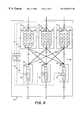
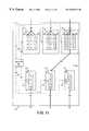
- FIG. 1illustrates the general architecture of a combined input-output buffered network device according to the present invention.
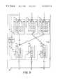
- FIG. 2illustrates an example configuration of a three by three network device showing input (IC) and output (OC) cells queued in the virtual output queues of input ports and in the output port queues of output ports.
- ICinput
- OCoutput
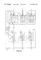
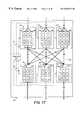
- FIG. 3illustrates an example of greedy output selection requests made in the first iteration of the greedy version of the LOOFA algorithm.
- FIG. 4illustrates an example of non-greedy output selection requests made in the first iteration of the non-greedy version of the LOOFA algorithm.
- FIG. 5illustrates greedy input selection grants made in the first iteration of the greedy version of the LOOFA algorithm, in response to the requests made in FIG. 3 .
- FIG. 6illustrates non-greedy input selection grants made in the first iteration of the non-greedy version of the LOOFA algorithm, in response to the requests made in FIG. 4 .
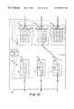
- FIG. 7illustrates an example of greedy output selection requests made in the second iteration of the greedy version of the LOOFA algorithm.
- FIG. 8illustrates greedy input selection grants made in the second iteration of the greedy version of the LOOFA algorithm, in response to the requests made in FIG. 7 .
- FIG. 9illustrates an example of non-greedy output selection requests made in the second iteration of the non-greedy version of the LOOFA algorithm.
- FIG. 10illustrates non-greedy input selection grants made in the second iteration of the non-greedy version of the LOOFA algorithm, in response to the requests made in FIG. 9 .
- FIG. 11illustrates an example of non-greedy output selection requests made in the third iteration of the non-greedy version of the LOOFA algorithm.
- FIG. 12illustrates non-greedy input selection grants made in the third iteration of the non-greedy version of the LOOFA algorithm, in response to the requests made in FIG. 11 .
- FIG. 13shows the cell transfers that take place at the end of the example phase after the successive iterations of both the greedy and non-greedy versions of LOOFA shown in FIGS. 3 through 12.
- FIG. 14illustrates an example of a round-robin input port indicator within each output port for use in making input selections according to the round-robin input selection algorithm.
- FIG. 15illustrates an example of a Last Service Time indicator within each input port for use in making input selections according to the Last Service Time input selection algorithm.
- FIG. 16illustrates an example of each queued input cell including a time stamp within the virtual output queues of each input port for use in making input selections according to the Oldest Cell First input selection algorithm.
- FIG. 17illustrates an embodiment of the invention that uses virtual input queues within the output ports of the network device.
- FIG. 18illustrates an example of a computer networking environment in which the present invention may operate.
- FIG. 19illustrates an interrelationship between time slots and phases as may occur in the invention so that the switch fabric may have a speedup of two.
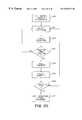
- FIG. 20illustrates a flow chart of the processing steps generally performed during a two phased time slot execution of LOOFA.
- FIG. 1is an illustration of the main internal components of an example combined input-output buffered network device, as configured according to the present invention.
- the example network deviceis a three by three combined input-output buffered (CIOB) network device, since it has three input and three output ports.
- CIOBcombined input-output buffered
- a three input by three output combined input-output buffered network deviceis illustrated for example purposes only.
- a network device according to the present inventionis not limited to using only three input and output port connections and in many common implementation will have many more ports.
- Network device 49comprises three input ports 50 , 51 and 52 and three output ports 59 , 60 and 61 .
- Each input port 50 , 51 and 52is connected to each output port 59 , 60 and 61 via connection channels 80 through 88 , which form the switch fabric 89 of the network device 49 .
- the switch fabric 89is implemented as a crossbar in one embodiment.
- each input and output portis shown as a separate port.
- a single port in a network devicemay serve as both an input and output port that is capable of both sending and receiving data over the same physical link.
- the portsare shown as separate input ports corresponding to separate output ports only for ease of description of the invention.
- each portmay selectively connected to all other ports, including itself, in order to transmit data through the network device.
- each input port 50 , 51 and 52has virtual output queues (VOQ's) 56 , 57 and 58 , each containing input buffers “a” through “d” for storing data.
- Each output port 59 , 60 and 61has an output port queue 65 containing output buffers “a” through “d” for storing data for transmission to output data links 62 , 63 and 64 , respectively.
- the buffer sizesmay be very large. Only four output buffers and input buffers are shown per queue in each figure due to drawing size limitations.
- a network devicereceives data on input ports and sends data from output ports.
- the datais received in a standardized format, such as TCP/IP datagrams, frames, or ATM cells for example. These units of data are generally referred to herein as packets for ease of description.
- each input port of a network device in this inventionis separate respective virtual output queues, one corresponding to each output port of that network device. As shown in FIG. 1, since there are three output ports 59 , 60 and 61 , there are three virtual output queues 56 , 57 and 58 associated with each input port 50 , 51 and 52 . If there were ten output ports, there would be ten virtual output queues associated with each input port.
- packets containing an address and dataarrive at the network device over input data links 53 , 54 and 55 .
- packetsarrive, they are analyzed by a routing algorithm implemented within route processor 30 , which makes forwarding decisions based on the address of the packet.
- the packets that arrive on an input portmay then be divided into fixed size cells by fragmentation processing logic.
- the cellsare reassembled back into a packet at the output port.
- the operation of the method and apparatusis discussed in relation to cells of data, where each cell is a fixed size.
- embodiments of the inventionmay treat the ATM cells the same as the cells within the network device.
- Each cellis given a header indicating an output port 59 , 60 or 61 in the network device to which that cell is to be forwarded.
- Each cellis then placed into the next available input buffer “a”, “b”, “c” or “d” in the virtual output queue 56 , 57 or 58 within the input port 50 , 51 or 52 .
- the virtual output queue selected to receive the cells of a packetcorresponds to the output port 59 , 60 or 61 to which that packet is to be sent, as determined by the routing algorithm used in route processor 30 .
- each virtual output queue 56 , 57 and 58is able to buffer the cells that must be transmitted to that virtual output queue's corresponding output port, either 59 , 60 or 61 , respectively.
- the process of receiving and queuing cells into the virtual output queues 56 , 57 and 58 of each input port 50 , 51 and 52is the input buffering portion of network device processing.
- the arbiter 90implements the Lowest (or Least) Occupancy Output First Algorithm (LOOFA).
- LEOFALowest Occupancy Output First Algorithm
- the arbiter 90determines which cells are repetitively removed from the virtual output queues 56 , 57 and 58 of each input port 50 , 51 and 52 and determines when the cells are transferred across connection channels 80 through 88 and then queued into the output port queues 65 of output ports 59 , 60 and 61 .
- the cellsremain queued in the output port queues 65 while the network device 49 re-assembles them into packets and unloads the packets onto the respective output data links 62 , 63 and 64 , according to the speed of those output data links. In this general manner, packets are switched between input and output ports.
- An arbitration algorithmOne goal of an arbitration algorithm is to allow the arbiter 90 to match as many connections across the network device as possible to maximize throughput.
- An arbitration algorithm that matches as many connections as possibleis a maximal matching algorithm, and achieving a fast arbitration algorithm is similar in nature to the maximal matching problem found in bipartite graphs.
- the LOOFA arbitration algorithmsets-up as many one-to-one connections as possible between input and output ports, and then the arbiter 90 controls the switch fabric 89 to transfer the cells across the network device. This process repeats itself for every cell transfer time slot. By controlling how fast the arbiter 90 executes the arbitration algorithm, the number of cell transfers over time may be controlled. Aside from the physical limitations of the switch fabric, the cell transfer rate controlled by the arbiter's arbitration algorithm determines the speed of the switch fabric. For example, if packets arrive at the network device on input data links at a certain data rate, and the arbiter can control the switch fabric according to the arbitration algorithm to transfer cells for packets at twice that data rate, then the switch fabric is said to have a speedup of two.
- FIG. 2illustrates a snapshot image of network device 49 configured according to the present invention, while processing cells.
- Queued input cells awaiting transmission across the switch fabric 89are shown by the letters “IC” in the input buffers of the input ports 50 , 51 and 52 that hold each cell.
- virtual output queue 56has three input cells (IC's) in respective input buffers (input buffer locations b, c, and d in input port 51 from FIG. 1) awaiting transfer across the connection channel 83 to output port 59 .
- virtual output queue 57has two cells queued (input buffer locations c and d in input port 51 from FIG. 1 ), each awaiting transfer across connection channel 84 to output port 60 .
- virtual output queue 58has two cells queued for transfer over connection channel 85 to output port 61 .
- Input ports 50 and 52also have cells queued as well, as shown by the input cell (IC) designators in FIG. 2 .
- the occupancy rating 72 of the output buffer 65 in output port 61is two, since there are two OC cells queued (OC cells queued at output buffer positions c and d from FIG. 1) in this output port.
- the occupancy rating 70 of output port 59 in FIG. 2is shown as one in this example, since only one OC cell is queued in its output port queue 65 .
- the rate at which packets are dequeued from the output port queues 65depends upon the data rates of the output data links 62 , 63 , and 64 . “In this draft, it is assumed that the input and output links are of the same capacity.”
- the occupancy ratings 70 , 71 and 72 of the output port queue 65 for each output port 59 , 60 and 61are used, as will be explained, to select appropriate connections for cell transfers.
- arbiter 90keeps track of how many OC cells are queued in the output buffers of each output port queue 65 for each output port 59 , 60 and 61 . In other words, the arbiter maintains the occupancy rating of each output port in the network device.
- the output queue with the lowest number of OC cells waiting to be sent from the network deviceis designated within the arbiter 90 as the output port with the least occupancy or lowest occupancy rating.
- output port 59has the lowest occupancy rating 70 of one, since only one output cell is queued.
- the occupancy ratings 70 , 71 and 72are shown in each output port 59 , 60 and 61 for ease of description.
- the inventionis not limited to maintaining these occupancy ratings within the output ports or within the arbiter. However, in preferred embodiments, the occupancy ratings are maintained within the arbiter itself.
- the speed at which the LOOFA algorithm operates within the arbiter 90determines the speed of the switch fabric.
- the network device arbitration and cell transfer operationis usually broken into time slots, as illustrated conceptually in the example timing diagram of a network device shown in FIG. 19 .
- LOOFAcan be generalized to deeper pipelines, thus obtaining higher throughput.
- a single time slotsuch as example time slot 27 , represents the period of time for the arrival rate of a single cell into one of the virtual output queues of an input port.
- the arbiter running LOOFAcan transfer twice as many cells across the switch fabric as the number that arrive at the virtual output queues.
- the arbiteroperates the switch fabric at a speedup of at least two.
- each time slot 27 and 28is broken into multiple phases 29 and 30 , and 31 and 32 , respectively.
- arbitrationoccurs as well as cell transfer.
- Arbitrationillustrated by processing blocks 20 through 23 in FIG. 19, refers to the setup of connections between input and output ports.
- Cell transferillustrated by processing blocks 24 , 25 and 26 , is the process of actually transferring the cells across the switch fabric of the network device between the input and output ports.
- a phasedefines the period of time in which as many input and output ports are matched as possible (arbitration) while at the same time, one group of cell transfers takes place (transfer) for connection matches made in the previous phase.
- the first arbitration 20takes place as input-output port connections are initially setup.
- cell transferstake place (transfers 24 , 25 , 26 , etc.) for the connections that were established in the previous phase, while at the same time, arbitration takes place (arbitrate blocks 21 , 22 , 23 , etc.) in order to set up the next group of connections to be transferred in the next phase, as indicated by the arrows in FIG. 19 .
- arbitration and cell transferoccur in parallel with each other in a phase. Since two phases occur in each time slot, two cells are transferred from each input port, one cell in each phase, for every one that arrives at the input port in a single time slot. Two phases per time slot thus provides a speedup of two in the switch fabric.
- multiple iterations of LOOFAoccur.
- One iteration of a phaseis one attempt by the arbiter running LOOFA to match as many input port virtual output queues with output ports.
- an iteration of the arbitration portion of a phaseis one output selection process followed with one input selection process. It may take multiple iterations of LOOFA until no more matches can be made between input and output ports, at which point the arbitration portion of that phase is complete.
- the cell transfer portionoccurs simultaneously with arbitration.
- the general operation of a phase of the arbiter running LOOFAcomprises the following five steps:
- Step 1Initially, all input ports and output ports are unmatched.
- Step 2Each unmatched input port selects the virtual output queue going to an unmatched output port with the lowest occupancy rating, and generates a request for that output port. (Output Selection)
- Step 3The output port(s), upon receiving requests from one or more input port(s), selects one input port according to an input selection algorithm, and generates a grant for that input port. (Input Selection)
- Step 4Repeat steps 2 and 3 until no more matches may be made between any input and output ports. (Perform multiple iterations until all ports matched)
- Step 5Transfer cells to complete this phase and repeat entire process beginning at Step 1.
- Each execution of steps 1 through 5 in the arbiteroccurs within one cell transfer phase to define the state of the switch fabric for the next cell transfer phase.
- at least two phasesare executed in a time slot, where a time slot is measured by the maximum arrival rate of cells at the top of the virtual output queues of the input ports. Accordingly, by executing LOOFA twice in one time slot, a speedup of two is realized in the switch fabric, thus potentially transferring twice as many cells across the switch fabric as can arrive at the virtual output queues of the input ports.
- LOOFAis optimal in terms of attainable speedup. That is, generally, a speedup of two is necessary and sufficient to provide the work conserving property when using LOOFA.
- FIG. 20illustrates the general processing steps performed by the network device during each time slot.
- step 300the cell arrives at an input port and phase and iteration variables are initialized to zero.
- steps 301 and 302the output and input selection processes take place, which are equivalent to steps 2 and 3 of LOOFA, as discussed above.
- Step 303determines if the iteration counter has exceeded the maximum iterations. If the maximum number of iterations has not been exceeded, steps 301 and 302 are repeated. If the maximum iterations of output and input selection have taken place, step 304 transfers the cells across the switch fabric and step 305 increments the phase counter (i.e., from zero to one in the first phase).
- step 306if the phase counter is less than two, which it will be during the first phase, steps 301 through 305 are repeated for the second phase. If the phase counter is equal to or greater than 2, then step 307 is processed at which point cell departures from the network device occur and the occupancy of the output ports is updated. Accordingly, in each phase of LOOFA, a cell transfer takes place, and in a time slot, a cell departure from the output port buffer takes place.
- FIGS. 3 through 13are abstracted as requests and grants between ports. Requests and grants, such as request 120 for example in FIG. 3, are shown by arrows in the figures, but, depending upon implementation details, embodied in a single variable setting or a message, for example, sent between functions within the arbiter 90 itself.
- FIG. 3conceptually shows greedy LOOFA requests.
- greedy LOOFAif any input port has any cells queued in any virtual output queue, indicating that those virtual output queues are active, the arbiter 90 can generate a request for that input port in the current iteration of the phase. More specifically, the request will be generated for the output port that has the lowest occupancy rating corresponding to one of the active virtual output queues in that input port.
- request 120is shown being generated from virtual output queue 56 in input port 50 to output port 59 , since when selecting between the only two active virtual output queues 56 and 57 in input port 50 , the arbiter 90 determines that virtual output queue 56 corresponds to output port 59 that has the lower occupancy rating between the two (occupancy ratings 70 and 71 , having ratings of one and three, respectively, as shown in FIG. 3 ).
- request 121is drawn from virtual output queue 56 in input port 52 to output port 59 , since when choosing between all three active virtual output queues 56 , 57 and 58 in input port 52 , the arbiter 90 always generates the request for the active virtual output queue corresponding to the unmatched output port having the lowest occupancy rating.
- each output port 59 , 60 and 61is available to receive a request, but the arbiter 90 only selects the output port associated with the active virtual output queues having the lowest occupancy rating, which is output port 59 having occupancy rating 70 of one) in this example.
- greedy LOOFAgenerates requests 120 , 121 and 122 .
- FIG. 4illustrates the distinction between greedy and non-greedy versions of LOOFA.
- an arbiter 90running the non-greedy LOOFA algorithm only makes a request from an unmatched input port during an iteration of a phase if that input port's virtual output queue corresponding to the lowest occupancy unmatched output port is active.
- only unmatched input ports 50 and 55prompt the generation of requests 123 and 124 , each associated with the respective virtual output queue 56 , since only within these input ports is virtual output queue 56 active, which corresponds to unmatched output port 59 , having the lowest occupancy rating of all unmatched output ports.
- input port 51does not make a request, since virtual output queue 56 in input port 51 is inactive, having no cells to send.
- step 2 of LOOFA, output selectionis complete. Once some or all of the unmatched output ports have received one or more associated requests and output selection is over, those unmatched output ports are then matched to a requesting input port via the input selection process. As shown in both the greedy and non-greedy versions of LOOFA in FIGS. 3 and 4, certain unmatched output ports may happen to have more than one associated request, indicating that more than one unmatched input port has IC cells for that output port.
- the arbiter 90determines, during input selection, which input ports get paired and hence matched with which output ports during this iteration of the current phase. This is conceptually done in the figures by showing the output ports “sending” a grant to the chosen input port, as shown in FIGS. 5 and 6, which correspond to FIGS. 3 and 4, respectively.
- FIG. 5shows the results of the greedy input selection process (Step 3 of LOOFA), based upon the requests generated in the previous description of FIG. 3 . Since unmatched output port 61 in FIG. 3 received only one request from input port 51 , the input selection process of step 3 of LOOFA will match these two ports without complication. However, since in FIG. 3, unmatched output port 59 received two requests, one each from input ports 50 and 52 , the arbiter 90 must decide which request 120 or 121 will receive a corresponding grant. In other words, the arbiter must decide which input port 50 or 52 will be allowed to transfer its cell to output port 59 in this phase. The decision marks the pairs of input and output ports as matched, and removes them from consideration in the next iteration, as will be explained.
- the arbitermakes the input selection decision for an output port receiving multiple requests based on an input selection algorithm.
- Various input selection algorithmsmay be used, such as a circular round-robin selection algorithm, a Last Service Time algorithm, or an Oldest Cell First algorithm, or others.
- the arbiter 90according to the input selection algorithm in use, matches output port 59 with requesting input port 50 as shown by grant 125 , and matches output port 61 with requesting input port 51 via grant 126 . Once all matches are made, the iteration is over.
- Greedy LOOFAis called “greedy” since more than one pair of ports may be matched in an iteration of a phase.
- FIG. 6shows the matching performed by the non-greedy version of LOOFA (also Step 3 of LOOFA), based upon the example non-greedy requests illustrated in example FIG. 4 .
- the non-greedy input selection processis similar. However, remember that during the non-greedy output selection process (Step 2), the only output port to ever receive requests in any one iteration is the one singular unmatched output port having the lowest occupancy rating across the switch. Thus, during the non-greedy input selection process (step 3), the only output port that needs to grant permission to a requesting input port to transmit a cell is the lowest occupancy output port. The decision is still performed with an input selection algorithm however.
- output port 59had the lowest occupancy rating and received all of its requests from input ports having cells destined for this unmatched output port. Accordingly, in FIG. 6 showing the non-greedy grants generated in response to the requests of FIG. 4, only input port 50 is matched with output port 59 , as shown by grant 127 . Once all the ports are paired or matched at the end of the iteration, those ports are removed from further output and input selection iterations by being marked as matched.
- steps 2 and 3 of LOOFAAfter steps 2 and 3 of LOOFA have been processed for one iteration in either the greedy and non-greedy versions of LOOFA, steps 2 and 3 are repeated for that version of LOOFA via step 4, until no more input and output ports may be matched.
- the number of unmatched input and output portsdiminishes. For example, in one iteration of non-greedy output and input selection, only the lowest occupancy output port will receive one or more requests and will be matched with one of the requesting input ports. Then, during the next iteration, this input and output port pair is not used in either selection process since it was previously marked as matched.
- some other unmatched output portwill be the one with the lowest occupancy rating for the next iteration and will receive requests from unmatched input ports and then will select one requesting input port with which to be matched.
- the iterations in both versionsrepeat until no more matches may be made.
- FIGS. 7 through 13illustrate the remaining iterations of both the greedy (FIGS. 7 and 8) and non-greedy (FIGS. 9 through 12) LOOFA examples.
- FIG. 13shows the cell transfers that take place after all matches have been made according to both versions of LOOFA.
- step 2 of LOOFAthe second iteration of greedy requests. Since in FIG. 5, input ports 50 and 51 were respectively matched with output ports 59 and 61 , the only remaining unmatched input and output ports remaining in FIG. 7 are input port 52 and output port 60 . Since input ports 52 has at least one cell waiting in virtual output queue 57 (i.e., virtual output queue 57 is active) which corresponds to output port 60 and output port 60 has the lowest occupancy rating of any remaining unmatched output ports, the arbiter generates request 128 , as illustrated from input port 52 to output port 60 . In FIG.
- step 3 of LOOFAillustrating the second iteration of greedy input selection grants (step 3 of LOOFA)
- input port 52is granted permission to send its cell to output port 60 by the arbiter 90 according to the input selection algorithm, as shown by grant 129 .
- grant 129At this point in greedy LOOFA, after the grant in FIG. 8 is processed, all input and output ports have been matched, and the end of the phase (step 5) will be processed, as will be explained shortly.
- FIGS. 9 through 12show the remaining output and input selection steps for the remaining iterations of the non-greedy LOOFA algorithm, as last discussed with respect to FIG. 6 . Since in FIG. 6, output port 59 granted input port 50 permission to transfer a cell, these two ports were matched. Hence, in FIG. 9, only input ports 51 and 52 and output ports 60 and 61 remain unmatched.
- step 2since both input pots 51 and 52 each have IC cells active in virtual output queue 58 destined for the lowest rated occupancy output port 61 , which has an occupancy rating 72 of two (versus the occupancy rating 71 of three for output port 60 ), each unmatched input port 51 and 52 has a request (requests 130 and 131 ) generated for output port 61 , as illustrated in the figure.
- step 2the second iteration of non-greedy input selection grants takes place and output port 61 has one of input ports 51 or 52 selected by the arbiter 90 according to an input selection algorithm.
- the arbiter 90selects input port 51 , and generates a grant 132 for input port 51 .
- the arbiterthus matches input port 51 with output port 61 .
- the arbitertypically makes these calculations for requests and grants internally according to an input selection algorithm.
- FIG. 11shows the request 133 generated for output port 60 from input port 52 , since input port 52 had an IC cell queued-up in virtual output queue 57 that was destined for output port 60 , and output port 60 , being the last and only unmatched output port, had the lowest occupancy rating.
- FIG. 12shows that output port 60 generates a grant 134 for input port 52 , since output port 60 only received the single request ( 133 in FIG. 11) from input port 52 .
- the arbiter 90has matched each input port to an output port according to the non-greedy version of LOOFA.
- non-greedy LOOFArequires at least N iterations in order to pair each input port with an output port, where N is the number of input ports. This is because in non-greedy LOOFA, only one match is made per iteration since only the single output port with the lowest occupancy rating receives requests and accordingly may only return one grant per iteration.
- greedy LOOFAallows the arbiter to pair up potentially more than one set of input and output ports, as shown in the previous example. Thus, in greedy LOOFA, less than N iterations of output and input selection typically occur before no more matches can be made. It has been empirically observed that using the greedy version of the algorithm operating with a speedup of 2, there are no new connections that get made beyond the third iteration.
- Cell transferstake place between the matched input and output ports (Step 5 of LOOFA) during the next phase, in which arbitration for the subsequent share begins.
- Cell transferrefers to the arbiter 90 signaling to the matched input ports to send one cell across the appropriate channel 80 through 88 in switch fabric 89 to the corresponding matched output port.
- FIG. 13shows the cell transfers that take place according to both examples of the greedy and non-greedy versions of the LOOFA algorithm.
- input port 50will transfer one cell from virtual output queue 56 to the output port queue 65 of output port 59
- input port 51will transfer one cell from virtual output queue 57 to the output port queue 65 of output port 61
- input port 52will transfer one cell from virtual output queue 58 to the output port queue 65 of output port 60 .
- the current phase of the current time slot in LOOFAis completed.
- the arbiterduring the input selection process, if more than one request is generated by the arbiter for a single output port, the arbiter must chose between two or more input ports from which to generate a grant and therefore receive a packet at the end of the current phase. This decision is made based upon the choice of input selection algorithm noted earlier. The arbiter uses the input selection algorithm to chose which input port gets a grant from an output port when more than one input port requests to send a cell to that output port.
- the input selection algorithmmay be performed in a variety of ways, each of which is within the scope of this invention.
- the arbitermay only generate a single grant for one of the input ports, the choice of implementation of the input selection algorithm (i.e., used in step 3 of LOOFA) will affect the fairness and delay properties of packets passing through the network device.
- Fairnessmay be partially affected based on the input selection algorithm used, as well as other factors which will be discussed later.
- fairnessrefers to the evenhandedness to which grants are generated for each entity contending for the network device's resources.
- the resource of a network devicee.g., router, switch
- An example of an entityis an input port.
- Fairnessaffects how fair the network device is to certain input ports in relation to other input ports that are waiting to transmit cells to the same output port. Fairness may be important in quality of service situations where a certain input data link for an input port is guaranteed a certain data rate. If the arbiter favors generating grants for this input port, the fairness of the switch may be altered to increase data rates for cells from that input port and therefore may move more data packets from the corresponding input data link.
- FIG. 14conceptually illustrates an example of a network device 49 including output ports 59 , 60 and 61 , each equipped with a round-robin pointer 150 , 151 , and 152 , respectively.
- Each round-robin pointer 150 , 151 and 152contains an indication of the current input port to which a grant should be sent, in the event of receiving multiple requests.
- step 3 of LOOFAwhen the arbiter 90 must decide, for an output port, which of multiple requesting input ports 50 , 51 or 52 gets a grant, the round-robin pointer is consulted for the requesting input port which is next in turn.
- the round-robin pointeris maintained as a counter within the arbiter or elsewhere.
- the round-robin pointeris shown within each output port in the figure for ease of description and association with the invention only, and is not meant to limit the invention as such. Moreover, occupancy characteristics and virtual output queue information and other input and output port statistical information may all be maintained with the arbiter.
- the figuresare conceptual in nature and do not limit the invention to embodiments illustrated therein.
- round-robin input selectionFor an example of round-robin input selection, suppose output port 60 received requests from input ports 50 , 51 and 52 . Using the round-robin algorithm for the input selection process in step 3 of LOOFA, input port 50 would be selected as the input port to receive the grant from output port 60 , since the round-robin pointer 151 for this output port contains the input port number 50 . After the grant is sent, the round-robin pointer 151 would be incremented by one to input port 51 . If a round-robin pointer identifies an input port which did not send a request, but the output port received multiple requests during step 2 of LOOFA, then the round-robin pointer for that output port would be incremented until its value was equal to one of the requesting input ports. In this manner, requesting input ports may be fairly selected.
- a random input selection algorithmAnother input selection algorithm that may be used in step 3 of LOOFA is referred to as a random input selection algorithm.
- this simple algorithmallows random selection of an input port to receive a grant when more than one input port requests to send a cell to an output port.
- the arbiterwhen scheduling cell transfers, randomly chooses which single input port, from the many requesting to send a cell, will get the grant.
- Various weighted random selection algorithmsmay be used as well, in place of a purely random selection process. The random algorithm and its variants are not illustrated in the drawings, due to their simplistic nature and random operation.
- FIG. 15illustrates a network device configured to use the Last Service Time algorithm.
- the last service timeis maintained for each VOQ (i.e., each input, output pair).
- the time stampindicates the last time this VOQ was able to send a cell. So the arbiter has to maintain N 2 time stamps: one each for each VOQ. After the cell gets transferred from a VOQ, the last service time for the VOQ gets updated to the current time.
- step 3 of LOOFAusing the Last Service Time input selection algorithm, the arbiter 90 would consult the time stamps 153 , 154 and 155 of each of these input ports for their time stamp values.
- a time stamp valueindicates how much time has passed since that input port has transferred a cell across the switch fabric 89 .
- the arbiter 90would generate a grant for the input port having the highest time stamp, in this example input port 51 , since input port 51 has been waiting the longest of the requesting input ports to transfer a cell, as indicated by its time stamp 154 having a value of 9.
- time stamp 154having a value of 9.
- FIG. 16illustrates a network device configured for yet another input selection algorithm that may be used in step 3 of LOOFA, referred to as Oldest Cell First.
- the network devicecan keep track of the lifetime of each cell queued in virtual output queues of each input port.
- each input buffer having a queued input cellindicates the time stamp of that cell as a numerical value in the cell input buffers.
- the head cell of virtual output queue 56(input buffer position “d” from FIG. 1) has a time stamp of 15, while the head cell of virtual output queue 57 has a time stamp or 03, and finally, the head cell of virtual output queue 58 has a time stamp of 01. The higher the time stamp number, the older the cell.
- the cell, or the pointer to the cell maintained in the arbiteris tagged with the current time stamp, indicating the time of cell arrival.
- each request sent in step 2 of LOOFAincludes a cell time stamp indication corresponding to the age of the cell that will be transmitted should that requesting input port receive the grant (i.e., requesting input ports with a cell waiting).
- step 3the arbiter 90 would generate the grant for input port 52 , since the cell from virtual output queue 56 in input port 52 had the oldest time stamp value of 15, as compared to the time stamp of 10 for the other request received from input port 50 .
- the requesting input port that contains the cell that has been in the network device for the longest timewill be granted permission to be transferred across the switch fabric, since the requests will indicate that the corresponding cell is the oldest. That is, the request will contains the time stamp of the cell as part of the request.
- the Oldest Cell First input selection algorithmimproves the delay properties of the network device by ensuring that no cell is queued much longer than any other.
- a time stampis included within the request.
- the time stampindicates the time of cell arrival; in the case of last service time, the time stamp indicates the last time that VOQ sent a cell.
- this inventionis concerned with, among other things, two important metrics; work-conservation and fairness. If a network designer using this invention is only concerned about throughput and data link utilization, the data in the output ports of a network device operating using LOOFA can be arranged simply in a First In, First Out (FIFO) manner, as shown in each of output port 59 , 60 and 61 in FIGS. 1 through 16.
- FIFOFirst In, First Out
- the head of the output buffer 65labeled as position ‘d’ in FIGS. 1 through 16 is selected from the FIFO queue and transferred onto the network data link. This simple dequeueing operation is performed for each data link for each output port, as fast as the data link can accept and send the data.
- VIQsvirtual input queues
- Output ports with VIQshave a bank of queues, one per input port.
- virtual input queuesallow each of the previously mentioned input selection algorithms to increase fairness for the network device.
- FIG. 17illustrates an example network device architecture that uses virtual input queues 101 , 102 and 103 within output ports 59 , 60 and 61 .
- a virtual input queue structure which buffers data in the output portsis very similar to the virtual output queues of the input ports.
- the arbiter 90maintains a pointer (not shown) to the head of each virtual input queue in each output port, and is therefore aware of each virtual input queue's occupancy rating.
- the input porti.e. the source
- the source input portmay be determined from header information within the cell itself, for example. For example, in FIG. 17, since virtual input queue 102 corresponds to input port 51 , all OC cells queued in virtual input queue 102 during operation will have been sent from input port 51 .
- the data link 62 , 63 or 64can select data from the next virtual input queue 101 , 102 or 103 for each output port 59 , 60 and 61 , according to, for example, a round-robin selection algorithm.
- the data or cell pointed to by the head of the selected virtual input queueis then transmitted onto the output data link 62 , 63 or 64 .
- Another input selection algorithmmay be used according to this invention that is generally only applicable to embodiments of the invention that use virtual input queues, such as the embodiment illustrated in FIG. 17 .
- This input selection algorithmis referred to as “Shortest Queue First”.
- an output portsuch as output port 60 in FIG. 17 receives requests from more than one input port, such as from each of input ports 50 , 51 and 52 in FIG. 17, the output port 60 examines each of its virtual input queues 101 , 102 and 103 to determine which has the shortest corresponding virtual input queue.
- the input port having the shortest corresponding virtual input queuewill be the input port which receives the grant to transmit a cell to the output port.
- VIQ 101 corresponding to requesting input port 50has a VIQ queue length or occupancy characteristic (indicated by the OC cells in each VIQ in FIG. 17) of one
- VIQ 102 corresponding to input port 51has a queue length of three
- VIQ 103 corresponding to input port 52has a queue length of four OC cells. Accordingly, since VIQ 101 is the shortest, input port 50 corresponding to this VIQ gets the grant.
- Table 1summarizes the features of the different input selection algorithms that may be used by the arbiter of the invention when determining which input ports receives a grant from an output port that has multiple requests from those input ports. Note that if two input ports requesting have a tie, for example, have equal length virtual input queues, then the tie is broken arbitrarily.
- the LOOFA arbitration algorithmcan operate at all times on all input and output ports having data to be transferred across the switch fabric. That is, during arbitration, all input and output ports can take part in arbitration, so long as data or cells are present to be sent.
- flow controlmay be required and used within the network device of this invention to control the amount of data input by any one input port through the switch fabric to an output port.
- each output portis responsible for turning on or off flow control to one or more input ports that are providing too many packets to that output port.
- the arbitertracks the occupancy rating of either the single FIFO output buffers (e.g. 65 in FIGS. 1 through 16) or the virtual input queues (e.g. 102 , 102 and 103 in FIG. 17) in each output port.
- the output portturns on flow control for either all input ports to that output port or for just the one input port sending to an overloaded VIQ.
- a flow control message from an output portinstructs all input ports to not send any more cells or requests to that output port.
- flow controlis turned on for the input port corresponding to that virtual input queue in that particular output port. As such, that input port stops sending cells and requests to that output port.
- flow controlcan be used to effectively deactivate entire output ports or an individual output port's virtual input queue for a number of successive iterations of the LOOFA algorithm, in order for the data queued in the overloaded FIFO or VIQ to be unloaded onto the network.
- Flow control for an input portmay be turned off when the number of cells in either the overloaded FIFO or the VIQ drops below the threshold level, as determined by the arbiter.
- requests generated by the arbiter for input ports and grants generated by the arbiter for output portsare contained and maintained within the arbiter itself. That is, the bulk of the input-output port connection decision making processing of FIGS. 3 through 13 is performed internally within the arbiter processing device 90 .
- the figuresshow the occupancy rating and, for example, round-robin pointer values, but those numbers are maintained within data structures or as registers within the arbiter 90 .
- bit vectorsmay be used within the arbiter as a means for tracking requests and grants within the arbiter.
- each input portsends a virtual output queue bit vector that indicates which virtual output queues in that input port have a cell queued to send to an output port, where each bit position in the bit vector represents a virtual output queue and output port paired association.
- the arbiterthen uses each virtual output queue bit vector from input ports to set a single request bit in a request bit vector in the bit position of the lowest occupancy output port.
- Each bit set in the request bit vector for an output portidentifies an input port requesting to send a packet to that output port. Then, the arbiter, using the round-robin pointer for example, selects one of those request bit positions in the request bit vector for each output port to represent the input port that will get the grant.
- the arbiterthen sets up a grant bit vector for each input port, with a bit set in the single virtual output queue position for that input port corresponding to the output port giving the grant. If no bits are set in the grant bit vector corresponding to an input port, then no grant was given to that input port.
- the bit vectorsmay be quickly sent between the arbiter and the input and output ports to communicate the necessary information about requests, grants and then cell transfers. In this manner, the arbiter quickly determines and processes requests and grants.
- the requests and grantsdo not actually exist as real messages at all. That is, the arbiter is a microprocessor running the LOOFA algorithm in software which performs most of the processing functionality of steps 1 through 5 of LOOFA internally using data structures and variables. In such an embodiment, the arbiter completes the processing of a phase of LOOFA, and determines which input ports should send cells to which output ports (i.e., the matched input-output pairs), the arbiter signals to the appropriate input ports to transmit certain cells at the appropriate time. The microprocessor obtains input data to track cell arrivals in virtual output queues and cells that are dequeued from output port queues, in order to keep the calculations accurate.
- the occupancy ratings of each output port's output port queueare kept internally within the arbiter in software or hardware.
- the virtual output queue activityis signaled internally to the arbiter via the input control lines (i.e., lines 91 , 92 and 93 in FIGS. 2 and 3 ). Keeping as much processing functionality of the invention within the arbiter increases the processing operation of the output and input selection portions of LOOFA, thus allowing faster switching of cells and therefore packets through the network device.
- a speedup of twofor the switch fabric, in conjunction with the novel LOOFA arbitration algorithm, provides a network device that is work conserving for all loads and that is equivalent in performance to a benchmark output buffered switch requiring much greater speedup of the switch fabric.
- a speedup of twomay be realized by operating the switch fabric via the arbiter at twice the speed of the input ports, as explained previously. That is, the arbiter performs the same connection set-up tasks as required for a speedup of one, but in one-half the time. This results in accomplishing twice as many packet transfers across the switching fabric in a single time slot.
- the arbiterschedules and transfers at most S cells or packets from an input port (i.e., from one of the virtual queues of an input port) to an output port, where S is the speedup.
- FIG. 18illustrates an example of a computer network 245 in which the present invention may advantageously operate.
- Host computers 210 through 221connect via data links 232 through 243 to network devices 222 through 225 .
- Network devices 222 through 225interconnect with each other over data links 226 through 231 in order to forward data between the hosts 210 through 221 .
- the datais typically sent from host 210 in packets onto data link 243 , which connects to an input port on network device 222 .
- Network device 222receives the data, transfers the data across an internal switching fabric (not shown in FIG. 18 ), and forwards the data from an output port onto data link 229 .
- Network device 225then receives the data on an input port coupled to data link 229 , transfers the data through its internal switching fabric, and forwards the data out of an output port onto data link 240 towards destination host 213 .
- Each network device 222 through 225 in FIG. 18has input ports that receive data, output ports that send data, and a switching fabric that allows data to be transferred between the input and output ports, all as previously described in this invention.
- the technology of the inventionmay be applied to the network devices 222 through 225 , which may for example be hubs, switches, routers, bridges and other forms of networked data transmission equipment that move data between multiple data links, sources, destinations, devices or networks.
- one or more of network devices 222 through 225may be a switch that transfers data packets between different network data links or segments.
- the network switchmay use the technology disclosed herein as the invention to its benefit. This is because a switch, for example, often must buffer packets on either side (i.e. input and output sides of connections within the switch) of the switch as the switch fabric transfers packets between each different network segment linked by the switch. Accordingly, switches buffering packets at input and outputs may be modeled as combined input-output buffered network devices and may apply the invention as disclosed.
Landscapes
- Engineering & Computer Science (AREA)
- Computer Networks & Wireless Communication (AREA)
- Signal Processing (AREA)
- Physics & Mathematics (AREA)
- Mathematical Physics (AREA)
- Data Exchanges In Wide-Area Networks (AREA)
Abstract
Description
| TABLE 1 |
| INPUT SELECTION ALGORITHM/OUTPUT PORT ACTION |
| OUTPUT PORT PROCESSING FOR | |
| SELECTING WHICH INPUT PORT | |
| INPUT | OF MANY REQUESTING INPUT |
| SELECTION ALGORITHM | PORTS GETS GRANT |
| Round-Robin | Output port ‘picks’ the |
| first ‘requesting’ input | |
| port which is pointed to by | |
| round-robin pointer, or | |
| next input port number | |
| after round-robin pointer | |
| Oldest Cell First, and | Output port ‘picks’ the |
| Last Service Time | ‘requesting’ input port |
| with the oldest time stamp | |
| sent along with the request | |
| Random | Output port randomly |
| ‘picks’ an input port from | |
| one of the requesting input | |
| ports. | |
| Shortest Queue First | Output port ‘picks’ the |
| requesting input port whose | |
| Virtual Input Queue (VIQ) | |
| in this output port has the | |
| shortest queue length. | |
Claims (41)
Priority Applications (7)
| Application Number | Priority Date | Filing Date | Title |
|---|---|---|---|
| US09/021,245US6563837B2 (en) | 1998-02-10 | 1998-02-10 | Method and apparatus for providing work-conserving properties in a non-blocking switch with limited speedup independent of switch size |
| EP99905944AEP1055350B1 (en) | 1998-02-10 | 1999-02-10 | Arbitration method and apparatus for a non-blocking switch |
| CA002319585ACA2319585A1 (en) | 1998-02-10 | 1999-02-10 | Arbitration method and apparatus for a non-blocking switch |
| AU25980/99AAU750787B2 (en) | 1998-02-10 | 1999-02-10 | Arbitration method and apparatus for a non-blocking switch |
| PCT/US1999/002921WO1999040754A1 (en) | 1998-02-10 | 1999-02-10 | Arbitration method and apparatus for a non-blocking switch |
| DE69940806TDE69940806D1 (en) | 1998-02-10 | 1999-02-10 | ARBITRATION METHOD AND DEVICE FOR A BLOCKING-FREE COUPLING FIELD |
| US09/257,725US6865154B1 (en) | 1998-01-12 | 1999-02-25 | Method and apparatus for providing bandwidth and delay guarantees in combined input-output buffered crossbar switches that implement work-conserving arbitration algorithms |
Applications Claiming Priority (1)
| Application Number | Priority Date | Filing Date | Title |
|---|---|---|---|
| US09/021,245US6563837B2 (en) | 1998-02-10 | 1998-02-10 | Method and apparatus for providing work-conserving properties in a non-blocking switch with limited speedup independent of switch size |
Related Parent Applications (1)
| Application Number | Title | Priority Date | Filing Date |
|---|---|---|---|
| US574098AContinuation-In-Part | 1998-01-12 | 1998-01-12 |
Related Child Applications (1)
| Application Number | Title | Priority Date | Filing Date |
|---|---|---|---|
| US09/257,725Continuation-In-PartUS6865154B1 (en) | 1998-01-12 | 1999-02-25 | Method and apparatus for providing bandwidth and delay guarantees in combined input-output buffered crossbar switches that implement work-conserving arbitration algorithms |
Publications (2)
| Publication Number | Publication Date |
|---|---|
| US20010050916A1 US20010050916A1 (en) | 2001-12-13 |
| US6563837B2true US6563837B2 (en) | 2003-05-13 |
Family
ID=21803157
Family Applications (1)
| Application Number | Title | Priority Date | Filing Date |
|---|---|---|---|
| US09/021,245Expired - LifetimeUS6563837B2 (en) | 1998-01-12 | 1998-02-10 | Method and apparatus for providing work-conserving properties in a non-blocking switch with limited speedup independent of switch size |
Country Status (6)
| Country | Link |
|---|---|
| US (1) | US6563837B2 (en) |
| EP (1) | EP1055350B1 (en) |
| AU (1) | AU750787B2 (en) |
| CA (1) | CA2319585A1 (en) |
| DE (1) | DE69940806D1 (en) |
| WO (1) | WO1999040754A1 (en) |
Cited By (54)
| Publication number | Priority date | Publication date | Assignee | Title |
|---|---|---|---|---|
| US20010038607A1 (en)* | 2000-04-06 | 2001-11-08 | Masahiko Honda | Packet switching system and method |
| US20010053157A1 (en)* | 2000-06-16 | 2001-12-20 | Li Shuo-Yen Robert | Self-routing device for switching packets of different lengths |
| US20020044546A1 (en)* | 2000-08-31 | 2002-04-18 | Magill Robert B. | Methods and apparatus for managing traffic through a buffered crossbar switch fabric |
| US20020061028A1 (en)* | 2000-11-20 | 2002-05-23 | Polytechnic University | Scheduling the dispatch of cells in multistage switches using a hierarchical arbitration scheme for matching non-empty virtual output queues of a module with outgoing links of the module |
| US20020118692A1 (en)* | 2001-01-04 | 2002-08-29 | Oberman Stuart F. | Ensuring proper packet ordering in a cut-through and early-forwarding network switch |
| US20030012210A1 (en)* | 2001-06-26 | 2003-01-16 | Andries Van Wageningen | Packet switching device with a feedback method of the arbiter |
| US20030016666A1 (en)* | 2001-07-18 | 2003-01-23 | Nec Corporation | Packet distributing apparatus and packet distributing method |
| US20030031197A1 (en)* | 2001-08-13 | 2003-02-13 | Schmidt Steven G. | Multiple arbitration circuit |
| US20030112797A1 (en)* | 2001-06-15 | 2003-06-19 | Li Shuo-Yen Robert | Scalable 2-stage interconnections |
| US20030118054A1 (en)* | 2001-06-15 | 2003-06-26 | Jian Zhu | Optimizing switching element for minimal latency |
| US20030126280A1 (en)* | 2001-12-31 | 2003-07-03 | Maxxan Systems, Inc. | XON/XOFF flow control for computer network |
| US20030123469A1 (en)* | 2001-12-31 | 2003-07-03 | Stmicroelectronics, Inc. | Scalable two-stage virtual output queuing switch and method of operation |
| US6636507B1 (en)* | 1999-03-08 | 2003-10-21 | Sony Corporation | Frame data exchanging method and apparatus |
| US20030212885A1 (en)* | 2002-05-08 | 2003-11-13 | Nec Corporation | Competitive management system and method for external input/output devices and recording medium recording program |
| US20030221019A1 (en)* | 2002-05-24 | 2003-11-27 | Fussell Andrew M. | Media bus interface arbitration for a data server |
| US20030227932A1 (en)* | 2002-06-10 | 2003-12-11 | Velio Communications, Inc. | Weighted fair share scheduler for large input-buffered high-speed cross-point packet/cell switches |
| US20040037558A1 (en)* | 2002-08-20 | 2004-02-26 | Nortel Networks Limited | Modular high-capacity switch |
| US6717945B1 (en)* | 2000-06-19 | 2004-04-06 | Northrop Grumman Corporation | Queue size arbitration method and apparatus to enhance performance of crossbar cell switch |
| US6721324B1 (en)* | 1998-06-26 | 2004-04-13 | Nec Corporation | Switch control system in ATM switching system |
| US20040081184A1 (en)* | 2002-06-27 | 2004-04-29 | Tellabs Operations, Inc. | Apparatus and method to switch packets using a switch fabric with memory |
| US20040081108A1 (en)* | 2002-10-02 | 2004-04-29 | Andiamo Systems | Arbitration system |
| US6735199B1 (en)* | 1999-11-09 | 2004-05-11 | Synchrodyne Networks, Inc. | Time frame switching responsive to global common time reference |
| US6754205B1 (en)* | 1999-03-04 | 2004-06-22 | Kabushiki Kaisha Toshiba | Switching element and packet switch |
| US6757282B1 (en)* | 1999-11-09 | 2004-06-29 | Synchrodyne Networks, Inc. | Fast switching of data packet with common time reference |
| US6757246B2 (en)* | 2001-08-14 | 2004-06-29 | Pts Corporation | Method and apparatus for weighted arbitration scheduling separately at the input ports and the output ports of a switch fabric |
| US6768736B1 (en) | 1998-12-30 | 2004-07-27 | Nortel Networks Limited | Using an ATM switch to grow the capacity of a switching stage |
| US6778538B2 (en)* | 1998-12-30 | 2004-08-17 | Nortel Networks Limited | Virtual junctors |
| US6781998B1 (en)* | 2000-04-07 | 2004-08-24 | Telefonaktiebolaget Lm Ericsson (Publ) | Random reordering system/method for use in ATM switching apparatus |
| US6788703B2 (en) | 1998-12-30 | 2004-09-07 | Nortel Networks Limited | DS0 on ATM, mapping and handling |
| US6788699B1 (en)* | 1999-10-20 | 2004-09-07 | Nec Corporation | Output buffer type asynchronous transfer mode switch |
| US6804229B2 (en) | 1998-12-30 | 2004-10-12 | Nortel Networks Limited | Multiple node network architecture |
| US6876649B1 (en)* | 1999-09-27 | 2005-04-05 | Nortel Networks Limited | High-capacity WDM-TDM packet switch |
| US6885661B1 (en) | 1998-12-30 | 2005-04-26 | Nortel Networks Limited | Private branch exchange built using an ATM Network |
| US20050105538A1 (en)* | 2003-10-14 | 2005-05-19 | Ananda Perera | Switching system with distributed switching fabric |
| US20050185582A1 (en)* | 2004-02-20 | 2005-08-25 | Samsung Electronics Co., Ltd. | Apparatus and method for managing traffic and quality of service in a high-speed router |
| US6963576B1 (en)* | 2000-09-28 | 2005-11-08 | Force10 Networks, Inc. | Scheduling and arbitration scheme for network processing device |
| US7016365B1 (en)* | 2000-03-31 | 2006-03-21 | Intel Corporation | Switching fabric including a plurality of crossbar sections |
| US7046685B1 (en)* | 1998-12-15 | 2006-05-16 | Fujitsu Limited | Scheduling control system and switch |
| US20060168380A1 (en)* | 2005-01-27 | 2006-07-27 | International Business Machines Corporation | Method, system, and storage medium for time and frequency distribution for bufferless crossbar switch systems |
| US20060171381A1 (en)* | 2005-01-31 | 2006-08-03 | Benner Alan F | Method, system, and storage medium for delay optimization for scheduling in bufferless crossbar switches |
| US7088710B1 (en)* | 1998-12-22 | 2006-08-08 | Xyratex Technology Limited | Method of transmitting information through data switching apparatus and apparatus therefor |
| US7106728B1 (en) | 2000-05-01 | 2006-09-12 | Industrial Technology Research Institute | Switching by multistage interconnection of concentrators |
| US7133399B1 (en)* | 2000-10-31 | 2006-11-07 | Chiaro Networks Ltd | System and method for router central arbitration |
| US20070053356A1 (en)* | 2003-10-30 | 2007-03-08 | Venkat Konda | Nonblocking and deterministic multirate multicast packet scheduling |
| US20080186961A1 (en)* | 2001-12-20 | 2008-08-07 | Kenneth Yi Yun | System and Method for Reevaluating Granted Arbitrated Bids |
| US20080256455A1 (en)* | 2001-12-14 | 2008-10-16 | Alberto Alessandro Della Ripa | Method for Defining the Physical Configuration of a Communication System |
| USRE42121E1 (en)* | 2000-01-12 | 2011-02-08 | New Jersey Institute Of Technology | Method and system for a hierarchical traffic shaper |
| US20110164616A1 (en)* | 2002-10-02 | 2011-07-07 | Andiamo Systems | Methods and apparatus for processing superframes |
| US7991926B1 (en)* | 2006-02-22 | 2011-08-02 | Marvell Israel (M.I.S.L) Ltd. | Scalable memory architecture for high speed crossbars using variable cell or packet length |
| USRE42600E1 (en)* | 2000-11-20 | 2011-08-09 | Polytechnic University | Scheduling the dispatch of cells in non-empty virtual output queues of multistage switches using a pipelined arbitration scheme |
| US8418129B1 (en) | 2001-12-14 | 2013-04-09 | Qualcomm Incorporated | Method for automatically generating code to define a system of hardware elements |
| US8964771B2 (en) | 2005-04-15 | 2015-02-24 | Altera Corporation | Method and apparatus for scheduling in a packet buffering network |
| US11019038B2 (en)* | 2016-02-03 | 2021-05-25 | Ted H. Szymanski | Methods to strengthen cyber-security and privacy in a deterministic internet of things |
| US11255287B2 (en)* | 2015-09-28 | 2022-02-22 | Westinghouse Air Brake Technologies Corporation | Apparatus and methods for allocating and indicating engine control authority |
Families Citing this family (38)
| Publication number | Priority date | Publication date | Assignee | Title |
|---|---|---|---|---|
| US6760331B1 (en) | 1999-03-31 | 2004-07-06 | Cisco Technology, Inc. | Multicast routing with nearest queue first allocation and dynamic and static vector quantization |
| US6603772B1 (en)* | 1999-03-31 | 2003-08-05 | Cisco Technology, Inc. | Multicast routing with multicast virtual output queues and shortest queue first allocation |
| JP2003529677A (en)* | 1999-07-29 | 2003-10-07 | シーメンス アクチエンゲゼルシヤフト | Heat resistant structural member and method of manufacturing the same |
| IL132694A (en)* | 1999-11-01 | 2003-10-31 | Terracross Ltd | Method and apparatus for high-speed, high-capacity packet-scheduling supporting quality of service in communications networks |
| JP3368881B2 (en) | 2000-01-07 | 2003-01-20 | 日本電気株式会社 | Input buffer type packet switch |
| US6731645B1 (en)* | 2000-02-29 | 2004-05-04 | International Business Machines Corporation | Methods, switches, systems, and computer program products for fair transmission of data received at multiple inputs in the order received in a queued memory switch |
| CA2402242C (en)* | 2000-03-10 | 2009-11-03 | Tellabs Operations, Inc. | Non-consecutive data readout scheduler |
| US6952419B1 (en)* | 2000-10-25 | 2005-10-04 | Sun Microsystems, Inc. | High performance transmission link and interconnect |
| US6848017B2 (en)* | 2000-10-26 | 2005-01-25 | Emc Corporation | Method and apparatus for determining connections in a crossbar switch |
| KR20020053664A (en)* | 2000-12-27 | 2002-07-05 | 오길록 | Terabit Packet Switching Apparatus with Brief Communicating Information for intermediation |
| US7042883B2 (en) | 2001-01-03 | 2006-05-09 | Juniper Networks, Inc. | Pipeline scheduler with fairness and minimum bandwidth guarantee |
| US7424027B2 (en)* | 2001-01-09 | 2008-09-09 | Lucent Technologies Inc. | Head of line blockage avoidance system and method of operation thereof |
| US20020136229A1 (en)* | 2001-01-09 | 2002-09-26 | Lucent Technologies, Inc. | Non-blocking crossbar and method of operation thereof |
| GB0102743D0 (en) | 2001-02-03 | 2001-03-21 | Power X Ltd | A data switch and a method for controlling the data switch |
| US7023840B2 (en)* | 2001-02-17 | 2006-04-04 | Alcatel | Multiserver scheduling system and method for a fast switching element |
| US6925520B2 (en)* | 2001-05-31 | 2005-08-02 | Sun Microsystems, Inc. | Self-optimizing crossbar switch |
| DE10128686A1 (en) | 2001-06-13 | 2002-12-19 | Philips Corp Intellectual Pty | Virtual output queue packet switching unit uses port controller status information |
| CA2356572A1 (en)* | 2001-08-30 | 2003-02-28 | Heng Liao | Transmit virtual concatenation processor |
| US7020131B1 (en)* | 2001-12-24 | 2006-03-28 | Applied Micro Circuits Corp. | System and method for hierarchical switching |
| US7660731B2 (en)* | 2002-04-06 | 2010-02-09 | International Business Machines Corporation | Method and apparatus for technology resource management |
| GB0208797D0 (en)* | 2002-04-17 | 2002-05-29 | Univ Cambridge Tech | IP-Capable switch |
| US7254113B2 (en) | 2002-09-18 | 2007-08-07 | Alcatel Lucent | Partially preemptive burst scheduling model for an optical burst switching network |
| AU2003260895A1 (en)* | 2002-10-02 | 2004-04-23 | Koninklijke Philips Electronics N.V. | Weight adaption in packet switches |
| US7349416B2 (en)* | 2002-11-26 | 2008-03-25 | Cisco Technology, Inc. | Apparatus and method for distributing buffer status information in a switching fabric |
| US20060140191A1 (en)* | 2004-12-29 | 2006-06-29 | Naik Uday R | Multi-level scheduling using single bit vector |
| US7724733B2 (en)* | 2005-03-31 | 2010-05-25 | International Business Machines Corporation | Interconnecting network for switching data packets and method for switching data packets |
| FR2891680B1 (en)* | 2005-09-30 | 2007-11-02 | Alcatel Sa | PACKET SWITCHING SYSTEM FOR COMMUNICATION NETWORK NODE |
| US20070268825A1 (en)* | 2006-05-19 | 2007-11-22 | Michael Corwin | Fine-grain fairness in a hierarchical switched system |
| US20090073968A1 (en)* | 2007-09-17 | 2009-03-19 | Integrated Device Technology, Inc. | Device with modified round robin arbitration scheme and method for transferring data |
| US7974278B1 (en)* | 2007-12-12 | 2011-07-05 | Integrated Device Technology, Inc. | Packet switch with configurable virtual channels |
| GB2461693B (en) | 2008-07-07 | 2012-08-15 | Micron Technology Inc | Switching method |
| TWI407312B (en)* | 2010-03-31 | 2013-09-01 | Feature Integration Technology Inc | Memory access apparatus and method thereof |
| US10122645B2 (en)* | 2012-12-07 | 2018-11-06 | Cisco Technology, Inc. | Output queue latency behavior for input queue based device |
| US9628406B2 (en) | 2013-03-13 | 2017-04-18 | Cisco Technology, Inc. | Intra switch transport protocol |
| US9860185B2 (en) | 2013-03-14 | 2018-01-02 | Cisco Technology, Inc. | Intra switch transport protocol |
| US9667564B2 (en)* | 2013-08-28 | 2017-05-30 | International Business Machines Corporation | Implementing hierarchical high radix switch with timesliced crossbar |
| US9467396B2 (en) | 2014-04-11 | 2016-10-11 | International Business Machines Corporation | Simultaneous transfers from a single input link to multiple output links with a timesliced crossbar |
| US12158855B2 (en)* | 2022-01-20 | 2024-12-03 | SambaNova Systems, Inc. | Dynamic equality of service in a switch network |
Citations (44)
| Publication number | Priority date | Publication date | Assignee | Title |
|---|---|---|---|---|
| US4823338A (en) | 1987-08-03 | 1989-04-18 | American Telephone And Telegraph Company | Virtual local area network |
| US4845710A (en) | 1986-12-23 | 1989-07-04 | Oki Electric Industry Co., Ltd. | Dynamic buffer supervising system for a data link access protocol control |
| US4933937A (en) | 1986-11-29 | 1990-06-12 | Kabushiki Kaisha Toshiba | Network adapter for connecting local area network to backbone network |
| EP0404337A2 (en) | 1989-06-22 | 1990-12-27 | Digital Equipment Corporation | High-speed mesh connected local area network |
| US5018133A (en) | 1987-11-18 | 1991-05-21 | Hitachi, Ltd. | Network system comprising a plurality of LANs using hierarchical routing |
| US5138615A (en) | 1989-06-22 | 1992-08-11 | Digital Equipment Corporation | Reconfiguration system and method for high-speed mesh connected local area network |
| US5237661A (en) | 1989-05-29 | 1993-08-17 | Hitachi, Ltd. | Buffer management method and system therefor using an I/O buffer on main memory and utilizing virtual memory and page fixing |
| US5321693A (en) | 1991-01-25 | 1994-06-14 | Digital Equipment Corporation | Multicast address in a local area network where the local area network has inadequate multicast addressing capability |
| US5367520A (en)* | 1992-11-25 | 1994-11-22 | Bell Communcations Research, Inc. | Method and system for routing cells in an ATM switch |
| US5394402A (en) | 1993-06-17 | 1995-02-28 | Ascom Timeplex Trading Ag | Hub for segmented virtual local area network with shared media access |
| US5473599A (en) | 1994-04-22 | 1995-12-05 | Cisco Systems, Incorporated | Standby router protocol |
| US5493566A (en)* | 1992-12-15 | 1996-02-20 | Telefonaktiebolaget L M. Ericsson | Flow control system for packet switches |
| US5500858A (en) | 1994-12-20 | 1996-03-19 | The Regents Of The University Of California | Method and apparatus for scheduling cells in an input-queued switch |
| WO1996008899A1 (en) | 1994-09-17 | 1996-03-21 | International Business Machines Corporation | Flow control method and apparatus for cell-based communication networks |
| GB2293720A (en) | 1994-09-30 | 1996-04-03 | Roke Manor Research | ATM queuing and scheduling apparatus |
| US5517495A (en) | 1994-12-06 | 1996-05-14 | At&T Corp. | Fair prioritized scheduling in an input-buffered switch |
| US5550823A (en)* | 1994-04-28 | 1996-08-27 | Nec Corporation | Method and apparatus for performing priority control for cells in output buffer type ATM switch |
| US5594732A (en) | 1995-03-03 | 1997-01-14 | Intecom, Incorporated | Bridging and signalling subsystems and methods for private and hybrid communications systems including multimedia systems |
| US5617421A (en) | 1994-06-17 | 1997-04-01 | Cisco Systems, Inc. | Extended domain computer network using standard links |
| US5619495A (en) | 1994-09-02 | 1997-04-08 | Mitsubishi Denki Kabushiki Kaisha | Cell switching apparatus and a cell switching system |
| US5621734A (en) | 1984-06-01 | 1997-04-15 | Digital Equipment Corporation | Local area network with server and virtual circuits |
| US5636215A (en) | 1994-12-27 | 1997-06-03 | Mitsubishi Denki Kabushiki Kaisha | Ring type ATM network system |
| US5689644A (en) | 1996-03-25 | 1997-11-18 | I-Cube, Inc. | Network switch with arbitration sytem |
| EP0817436A2 (en) | 1996-06-27 | 1998-01-07 | Xerox Corporation | Packet switched communication system |
| US5734865A (en) | 1995-06-07 | 1998-03-31 | Bull Hn Information Systems Inc. | Virtual local area network well-known port routing mechanism for mult--emulators in an open system environment |
| US5737528A (en) | 1993-07-16 | 1998-04-07 | Kabushiki Kaisha Toshiba | Network connecting apparatus with separate data and control signal lines |
| US5768257A (en) | 1996-07-11 | 1998-06-16 | Xylan Corporation | Input buffering/output control for a digital traffic switch |
| US5774453A (en)* | 1995-04-18 | 1998-06-30 | Nec Corporation | Input/output buffer type ATM switch |
| US5805816A (en) | 1992-05-12 | 1998-09-08 | Compaq Computer Corp. | Network packet switch using shared memory for repeating and bridging packets at media rate |
| US5808056A (en) | 1995-10-31 | 1998-09-15 | Merck & Co., Inc. | Process for preparing substituted azetidinones |
| US5838677A (en) | 1995-04-18 | 1998-11-17 | Hitachi, Ltd. | Switching system having means for congestion control by monitoring packets in a shared buffer and by suppressing the reading of packets from input buffers |
| US5859835A (en) | 1996-04-15 | 1999-01-12 | The Regents Of The University Of California | Traffic scheduling system and method for packet-switched networks |
| US5892922A (en) | 1997-02-28 | 1999-04-06 | 3Com Corporation | Virtual local area network memory access system |
| US5892766A (en) | 1996-02-22 | 1999-04-06 | Fujitsu, Ltd. | Method and apparatus for coordinating access to an output of a routing device in a packet switching network |
| US5959991A (en)* | 1995-10-16 | 1999-09-28 | Hitachi, Ltd. | Cell loss priority control method for ATM switch and ATM switch controlled by the method |
| US5978359A (en) | 1995-07-19 | 1999-11-02 | Fujitsu Network Communications, Inc. | Allocated and dynamic switch flow control |
| US6052376A (en)* | 1996-12-30 | 2000-04-18 | Hyundai Electronics America | Distributed buffering system for ATM switches |
| US6122252A (en)* | 1996-06-21 | 2000-09-19 | Hitachi, Ltd. | Packet switching device and cell transfer control method |
| US6122251A (en)* | 1996-11-13 | 2000-09-19 | Nec Corporation | Switch control circuit and control method of ATM switchboard |
| US6134217A (en) | 1996-04-15 | 2000-10-17 | The Regents Of The University Of California | Traffic scheduling system and method for packet-switched networks with fairness and low latency |
| US6144635A (en)* | 1996-07-18 | 2000-11-07 | Nec Corporation | Asynchronous transfer mode exchange system |
| US6188690B1 (en) | 1996-12-12 | 2001-02-13 | Pmc-Sierra, Inc. | Method and apparatus for high speed, scalable communication system |
| US6324165B1 (en) | 1997-09-05 | 2001-11-27 | Nec Usa, Inc. | Large capacity, multiclass core ATM switch architecture |
| US6377583B1 (en)* | 1996-06-27 | 2002-04-23 | Xerox Corporation | Rate shaping in per-flow output queued routing mechanisms for unspecified bit rate service |
- 1998
- 1998-02-10USUS09/021,245patent/US6563837B2/ennot_activeExpired - Lifetime
- 1999
- 1999-02-10CACA002319585Apatent/CA2319585A1/ennot_activeAbandoned
- 1999-02-10DEDE69940806Tpatent/DE69940806D1/ennot_activeExpired - Lifetime
- 1999-02-10AUAU25980/99Apatent/AU750787B2/ennot_activeCeased
- 1999-02-10EPEP99905944Apatent/EP1055350B1/ennot_activeExpired - Lifetime
- 1999-02-10WOPCT/US1999/002921patent/WO1999040754A1/enactiveIP Right Grant
Patent Citations (49)
| Publication number | Priority date | Publication date | Assignee | Title |
|---|---|---|---|---|
| US5621734A (en) | 1984-06-01 | 1997-04-15 | Digital Equipment Corporation | Local area network with server and virtual circuits |
| US4933937A (en) | 1986-11-29 | 1990-06-12 | Kabushiki Kaisha Toshiba | Network adapter for connecting local area network to backbone network |
| US4845710A (en) | 1986-12-23 | 1989-07-04 | Oki Electric Industry Co., Ltd. | Dynamic buffer supervising system for a data link access protocol control |
| US4823338B1 (en) | 1987-08-03 | 1998-11-10 | At & T Information Systems Inc | Virtual local area network |
| US4823338A (en) | 1987-08-03 | 1989-04-18 | American Telephone And Telegraph Company | Virtual local area network |
| US5018133A (en) | 1987-11-18 | 1991-05-21 | Hitachi, Ltd. | Network system comprising a plurality of LANs using hierarchical routing |
| US5237661A (en) | 1989-05-29 | 1993-08-17 | Hitachi, Ltd. | Buffer management method and system therefor using an I/O buffer on main memory and utilizing virtual memory and page fixing |
| EP0404337A2 (en) | 1989-06-22 | 1990-12-27 | Digital Equipment Corporation | High-speed mesh connected local area network |
| US5138615A (en) | 1989-06-22 | 1992-08-11 | Digital Equipment Corporation | Reconfiguration system and method for high-speed mesh connected local area network |
| US5321693A (en) | 1991-01-25 | 1994-06-14 | Digital Equipment Corporation | Multicast address in a local area network where the local area network has inadequate multicast addressing capability |
| US5805816A (en) | 1992-05-12 | 1998-09-08 | Compaq Computer Corp. | Network packet switch using shared memory for repeating and bridging packets at media rate |
| US5367520A (en)* | 1992-11-25 | 1994-11-22 | Bell Communcations Research, Inc. | Method and system for routing cells in an ATM switch |
| US5493566A (en)* | 1992-12-15 | 1996-02-20 | Telefonaktiebolaget L M. Ericsson | Flow control system for packet switches |
| US5394402A (en) | 1993-06-17 | 1995-02-28 | Ascom Timeplex Trading Ag | Hub for segmented virtual local area network with shared media access |
| US5737528A (en) | 1993-07-16 | 1998-04-07 | Kabushiki Kaisha Toshiba | Network connecting apparatus with separate data and control signal lines |
| US5473599A (en) | 1994-04-22 | 1995-12-05 | Cisco Systems, Incorporated | Standby router protocol |
| US5550823A (en)* | 1994-04-28 | 1996-08-27 | Nec Corporation | Method and apparatus for performing priority control for cells in output buffer type ATM switch |
| US5617421A (en) | 1994-06-17 | 1997-04-01 | Cisco Systems, Inc. | Extended domain computer network using standard links |
| US5619495A (en) | 1994-09-02 | 1997-04-08 | Mitsubishi Denki Kabushiki Kaisha | Cell switching apparatus and a cell switching system |
| WO1996008899A1 (en) | 1994-09-17 | 1996-03-21 | International Business Machines Corporation | Flow control method and apparatus for cell-based communication networks |
| GB2293720A (en) | 1994-09-30 | 1996-04-03 | Roke Manor Research | ATM queuing and scheduling apparatus |
| US5517495A (en) | 1994-12-06 | 1996-05-14 | At&T Corp. | Fair prioritized scheduling in an input-buffered switch |
| US5500858A (en) | 1994-12-20 | 1996-03-19 | The Regents Of The University Of California | Method and apparatus for scheduling cells in an input-queued switch |
| US5636215A (en) | 1994-12-27 | 1997-06-03 | Mitsubishi Denki Kabushiki Kaisha | Ring type ATM network system |
| US5594732A (en) | 1995-03-03 | 1997-01-14 | Intecom, Incorporated | Bridging and signalling subsystems and methods for private and hybrid communications systems including multimedia systems |
| US5774453A (en)* | 1995-04-18 | 1998-06-30 | Nec Corporation | Input/output buffer type ATM switch |
| US5838677A (en) | 1995-04-18 | 1998-11-17 | Hitachi, Ltd. | Switching system having means for congestion control by monitoring packets in a shared buffer and by suppressing the reading of packets from input buffers |
| US5734865A (en) | 1995-06-07 | 1998-03-31 | Bull Hn Information Systems Inc. | Virtual local area network well-known port routing mechanism for mult--emulators in an open system environment |
| US5978359A (en) | 1995-07-19 | 1999-11-02 | Fujitsu Network Communications, Inc. | Allocated and dynamic switch flow control |
| US5996019A (en) | 1995-07-19 | 1999-11-30 | Fujitsu Network Communications, Inc. | Network link access scheduling using a plurality of prioritized lists containing queue identifiers |
| US5982776A (en) | 1995-07-19 | 1999-11-09 | Fujitsu Network Communications, Inc. | Multipoint-to-point arbitration in a network switch |
| US5982771A (en) | 1995-07-19 | 1999-11-09 | Fujitsu Network Communications, Inc. | Controlling bandwidth allocation using a pace counter |
| US5959991A (en)* | 1995-10-16 | 1999-09-28 | Hitachi, Ltd. | Cell loss priority control method for ATM switch and ATM switch controlled by the method |
| US5808056A (en) | 1995-10-31 | 1998-09-15 | Merck & Co., Inc. | Process for preparing substituted azetidinones |
| US5892766A (en) | 1996-02-22 | 1999-04-06 | Fujitsu, Ltd. | Method and apparatus for coordinating access to an output of a routing device in a packet switching network |
| US5689644A (en) | 1996-03-25 | 1997-11-18 | I-Cube, Inc. | Network switch with arbitration sytem |
| US6134217A (en) | 1996-04-15 | 2000-10-17 | The Regents Of The University Of California | Traffic scheduling system and method for packet-switched networks with fairness and low latency |
| US5859835A (en) | 1996-04-15 | 1999-01-12 | The Regents Of The University Of California | Traffic scheduling system and method for packet-switched networks |
| US6122252A (en)* | 1996-06-21 | 2000-09-19 | Hitachi, Ltd. | Packet switching device and cell transfer control method |
| EP0817436A2 (en) | 1996-06-27 | 1998-01-07 | Xerox Corporation | Packet switched communication system |
| US6377583B1 (en)* | 1996-06-27 | 2002-04-23 | Xerox Corporation | Rate shaping in per-flow output queued routing mechanisms for unspecified bit rate service |
| US5768257A (en) | 1996-07-11 | 1998-06-16 | Xylan Corporation | Input buffering/output control for a digital traffic switch |
| US6144635A (en)* | 1996-07-18 | 2000-11-07 | Nec Corporation | Asynchronous transfer mode exchange system |
| US6122251A (en)* | 1996-11-13 | 2000-09-19 | Nec Corporation | Switch control circuit and control method of ATM switchboard |
| US6188690B1 (en) | 1996-12-12 | 2001-02-13 | Pmc-Sierra, Inc. | Method and apparatus for high speed, scalable communication system |
| US6345050B1 (en) | 1996-12-12 | 2002-02-05 | Pmc-Sierra, Inc. | Method for manipulating cells in a high speed communication system |
| US6052376A (en)* | 1996-12-30 | 2000-04-18 | Hyundai Electronics America | Distributed buffering system for ATM switches |
| US5892922A (en) | 1997-02-28 | 1999-04-06 | 3Com Corporation | Virtual local area network memory access system |
| US6324165B1 (en) | 1997-09-05 | 2001-11-27 | Nec Usa, Inc. | Large capacity, multiclass core ATM switch architecture |
Non-Patent Citations (20)
| Title |
|---|
| "A 160-Gb/s ATM Swithcing System using an Internal Speed-up Crossbar Switch," Genda, et al, NTT Network Systems Laboratories, NTT Electronics Technology, Inc., NTT LSI Laboratories, Nov. 28, 1994, pp. 123-133. |
| "ATM Switch Architectures with Input-Output Buffering: Effect of Input Traffic . . . ," Badran, et al, Computer Networks and ISND Systems, May 26, 1994, Issue No. 9, pp. 1187-1213. |
| "Draft Standard P802.10/D7" IEEE Standards for Local and Metropolitan Area Networks: Virtual Bridged Local Area Networks, Oct. 3, 1997, XP002103631. |
| Anderson T., Owicki S., Saxe J., Thacker C., "High Speed Switch Scheduling for Local Area Networks", Proc. Fifth Internt. Conf. on Architectural Support for Programming Languages and Operating Systems, Oct. 1992, pp. 98-110. |
| Bennett J. and Zhang H., "WF2Q--Worst-case Fair Weighted Fair Queuing", Proc. IEEE INFOCOM '96. |
| Chang C-Y et al.: "A Broadband Packet Switch Architecture with Input and Output Queuing" Proceedings of the Global Telecommunications Conference (Globecom), San Francisco, Nov. 28-Dec. 2, 1994, vol. 1, Nov. 28, 1994, pp. 448-452, XP000488590 Institute of Electrical and Electronics Engineers. |
| Charny A., "Hierarchical Relative Error Scheduler: An Efficient Traffic Shaper for Packet Switching Networks," Proc. NOSSDAV '97, May 1997, pp. 283-294. |
| Guerin R. and Sivarajan K., "Delay and Throughput Performance of Speeded-up Input-Queuing Packet Switches," IBM Research Report RC 20892, Jun. 1997. |
| Liu N. H. et al., "A New Packet Scheduling Algorithm for Input-Buffered Multicast Packet Switches" IEEE Global Telecommunications Conference, Phoenix, Arizona, Nov. 3-8, 1997, vol. 3, Nov. 3-8, 1997, vol. 3, Nov. 3, 1997, pp. 1695-1699, XP000737812 Institute of Electrical and Electronics Engineers. |
| Mark B. L. et al; "Large Capacity Multiclass ATM Core Switch Architecture" ISS '97, World Telecommunications Congress, (International Switching Symposium), Global Network Evolution: Convergence or Collission? Toronto, Sep. 21-26, 1997, vol. 1, Sep.21, 1997, pp. 417-423 |
| Mark B. L. et al; "Large Capacity Multiclass ATM Core Switch Architecture" ISS '97, World Telecommunications Congress, (International Switching Symposium), Global Network Evolution: Convergence or Collission? Toronto, Sep. 21-26, 1997, vol. 1, Sep.21, 1997, pp. 417-423 XP0000720547. |
| McKeown N., "Scheduling Algorithms for Input-Queued Cell Switches," Ph.D.Thesis, Univ. of California, Berkeley, May 1995. |
| McKeown N., Anatharam V, and Warland J., "Achieving 100% Throughput in an Input-Queued Switch," Proc. IEEE INFOCOM '96, Mar. 1996, pp. 296-302. |
| McKeown N., Izzard M., Mekkittikul A., Ellersick W. and Horowitz M., "The Tiny Tera: A Packet Switch Core." |
| McKeown N., Prabahaker B., and Zhu M., "Matching Output Queuing with Combined Input and Output Queuing,"Proc. 35th Annual Allerton Conference on Communications, Control, and Computing, Monticello, Illinois, Oct. 1997. |
| Parekh, A., "A Generalized Processor Sharing Approach to Flow Control in Integrated Services Networks", MIT, Ph.D. dissertation, Jun. 1994. |
| Prabhaker B. and McKeown N., "On the Speedup Required for Combined Input and Output Queued Switching," Computer Systems Lab. Technical Report CSL-TR-97-738, Stanford University. |
| Prabhaker B. et al.: "Multicast Scheduling for Input-Queued Switches" IEEE Journal on Selected Areas in Communications, vol. 15, No. 5, Jun. 1997, pp. 855-866, XP000657037 see paragraph 1. |
| Stiliadis D. and Varma, A., "Frame-Based Fair Queuing: A New Traffic Scheduling Algorithm for Packet Switch Networks", Proc. IEEE INFOCOM '96. |
| Zhang L., "A New Architecture for Packet Switched Network Protocols," Massachusetts Institute of Technology, Ph.D. Dissertation, Jul. 1989. |
Cited By (118)
| Publication number | Priority date | Publication date | Assignee | Title |
|---|---|---|---|---|
| US6721324B1 (en)* | 1998-06-26 | 2004-04-13 | Nec Corporation | Switch control system in ATM switching system |
| US7046685B1 (en)* | 1998-12-15 | 2006-05-16 | Fujitsu Limited | Scheduling control system and switch |
| US7088710B1 (en)* | 1998-12-22 | 2006-08-08 | Xyratex Technology Limited | Method of transmitting information through data switching apparatus and apparatus therefor |
| US6804229B2 (en) | 1998-12-30 | 2004-10-12 | Nortel Networks Limited | Multiple node network architecture |
| US6768736B1 (en) | 1998-12-30 | 2004-07-27 | Nortel Networks Limited | Using an ATM switch to grow the capacity of a switching stage |
| US6778538B2 (en)* | 1998-12-30 | 2004-08-17 | Nortel Networks Limited | Virtual junctors |
| US6788703B2 (en) | 1998-12-30 | 2004-09-07 | Nortel Networks Limited | DS0 on ATM, mapping and handling |
| US6885661B1 (en) | 1998-12-30 | 2005-04-26 | Nortel Networks Limited | Private branch exchange built using an ATM Network |
| US6754205B1 (en)* | 1999-03-04 | 2004-06-22 | Kabushiki Kaisha Toshiba | Switching element and packet switch |
| US6636507B1 (en)* | 1999-03-08 | 2003-10-21 | Sony Corporation | Frame data exchanging method and apparatus |
| US6876649B1 (en)* | 1999-09-27 | 2005-04-05 | Nortel Networks Limited | High-capacity WDM-TDM packet switch |
| US6788699B1 (en)* | 1999-10-20 | 2004-09-07 | Nec Corporation | Output buffer type asynchronous transfer mode switch |
| US6757282B1 (en)* | 1999-11-09 | 2004-06-29 | Synchrodyne Networks, Inc. | Fast switching of data packet with common time reference |
| US6735199B1 (en)* | 1999-11-09 | 2004-05-11 | Synchrodyne Networks, Inc. | Time frame switching responsive to global common time reference |
| USRE42121E1 (en)* | 2000-01-12 | 2011-02-08 | New Jersey Institute Of Technology | Method and system for a hierarchical traffic shaper |
| US7016365B1 (en)* | 2000-03-31 | 2006-03-21 | Intel Corporation | Switching fabric including a plurality of crossbar sections |
| US20100238948A1 (en)* | 2000-04-06 | 2010-09-23 | Juniper Networks, Inc. | Packet switching system and method |
| US7756013B2 (en) | 2000-04-06 | 2010-07-13 | Juniper Networks, Inc. | Packet switching system and method |
| US8614942B2 (en) | 2000-04-06 | 2013-12-24 | Juniper Networks, Inc. | Packet switching system and method |
| US20010038607A1 (en)* | 2000-04-06 | 2001-11-08 | Masahiko Honda | Packet switching system and method |
| US7116633B2 (en)* | 2000-04-06 | 2006-10-03 | Juniper Networks, Inc. | Packet switching system and method |
| US20060285488A1 (en)* | 2000-04-06 | 2006-12-21 | Juniper Networks, Inc. | Packet switching system and method |
| US6781998B1 (en)* | 2000-04-07 | 2004-08-24 | Telefonaktiebolaget Lm Ericsson (Publ) | Random reordering system/method for use in ATM switching apparatus |
| US7106728B1 (en) | 2000-05-01 | 2006-09-12 | Industrial Technology Research Institute | Switching by multistage interconnection of concentrators |
| US7042878B2 (en) | 2000-06-16 | 2006-05-09 | Industrial Technology Research Institute | General self-routing mechanism for multicasting control over bit-permuting switching networks |
| US7079532B2 (en) | 2000-06-16 | 2006-07-18 | Industrial Technology Research Institute | Multistage interconnection networks of multicast concentrators with self-routing control mechanism |
| US7292570B2 (en) | 2000-06-16 | 2007-11-06 | Industrial Technology Research Institute | Self-routing device for switching packets of different lengths |
| US7035254B2 (en) | 2000-06-16 | 2006-04-25 | Industrial Technology Research Institute | Conditionally nonblocking switch of the upturned compressor type |
| US7280538B2 (en) | 2000-06-16 | 2007-10-09 | Industrial Technology Research Institute | Multicast concentrators |
| US7274689B2 (en)* | 2000-06-16 | 2007-09-25 | Industrial Technology Research Institute | Packet switch with one-stop buffer in memory with massive parallel access |
| US20010053157A1 (en)* | 2000-06-16 | 2001-12-20 | Li Shuo-Yen Robert | Self-routing device for switching packets of different lengths |
| US7139266B2 (en) | 2000-06-16 | 2006-11-21 | Industrial Technology Research Institute | Configuring equivalent multi-stage interconnection networks in the bit-permuting style |
| US7136380B2 (en) | 2000-06-16 | 2006-11-14 | Industrial Technology Research Institute | Conditionally nonblocking switch of the compressor type |
| US7031303B2 (en) | 2000-06-16 | 2006-04-18 | Industrial Technology Research Institute | Conditionally nonblocking switch of the upturned decompressor type |
| US20010055304A1 (en)* | 2000-06-16 | 2001-12-27 | Li Shuo-Yen Robert | Switching concentrator |
| US20030063602A1 (en)* | 2000-06-16 | 2003-04-03 | Li Shuo-Yen Robert | Conditionally nonblocking switch of the decompressor type |
| US20030053456A1 (en)* | 2000-06-16 | 2003-03-20 | Li Shuo-Yen Robert | Multicast concentrators |
| US20020012356A1 (en)* | 2000-06-16 | 2002-01-31 | Li Shuo-Yen Robert | Packet switch with one-stop buffer in memory with massive parallel access |
| US20020031124A1 (en)* | 2000-06-16 | 2002-03-14 | Li Shuo-Yen Robert | Multistage interconnection networks of multicast concentrators with self-routing control mechanism |
| US7099314B2 (en) | 2000-06-16 | 2006-08-29 | Industrial Technology Research Institute | General self-routing control mechanism over bit-permuting switching networks |
| US20020024951A1 (en)* | 2000-06-16 | 2002-02-28 | Li Shuo-Yen Robert | General self-routing mechanism for multicasting control over bit-permuting switching networks |
| US20020097714A1 (en)* | 2000-06-16 | 2002-07-25 | Li Shuo-Yen Robert | Generalized divide-and-conquer networks |
| US20020093950A1 (en)* | 2000-06-16 | 2002-07-18 | Li Shuo-Yen Robert | Physical implementation of switching fabrics constructed from recursive 2-stage interconnection |
| US7042873B2 (en) | 2000-06-16 | 2006-05-09 | Industrial Technology Research Institute | Conditionally non blocking switch of the circular-unimodal type |
| US7072334B2 (en) | 2000-06-16 | 2006-07-04 | Industrial Technology Research Institute | Physical implementation of switching fabrics constructed from recursive 2-stage interconnection |
| US7016345B2 (en) | 2000-06-16 | 2006-03-21 | Industrial Technology Research Institute | Conditionally nonblocking switch of the expander type |
| US7050429B2 (en) | 2000-06-16 | 2006-05-23 | Industrial Technology Research Institute | Conditionally nonblocking switch of the decompressor type |
| US6999466B2 (en) | 2000-06-16 | 2006-02-14 | Industrial Technology Research Institute | Switching concentrator |
| US7065073B2 (en) | 2000-06-16 | 2006-06-20 | Industrial Technology Research Institute | Self-routing control mechanism over multistage interconnection networks of concentrators |
| US7065074B2 (en) | 2000-06-16 | 2006-06-20 | Industrial Technology Research Institute | Generalized divide-and-conquer networks |
| US20020094151A1 (en)* | 2000-06-16 | 2002-07-18 | Li Shuo-Yen Robert | Conditionally nonblocking switch of the upturned compressor type |
| US6999461B2 (en) | 2000-06-16 | 2006-02-14 | Industrial Technology Research Institute | Routing schemes for packet switching networks |
| US20020051447A1 (en)* | 2000-06-16 | 2002-05-02 | Li Shuo-Yen Robert | General self-routing control mechanism over bit-permuting switching networks |
| US6717945B1 (en)* | 2000-06-19 | 2004-04-06 | Northrop Grumman Corporation | Queue size arbitration method and apparatus to enhance performance of crossbar cell switch |
| US20020044546A1 (en)* | 2000-08-31 | 2002-04-18 | Magill Robert B. | Methods and apparatus for managing traffic through a buffered crossbar switch fabric |
| US6915372B2 (en)* | 2000-08-31 | 2005-07-05 | Tellabs Operations, Inc. | Methods and apparatus for managing traffic through a buffered crossbar switch fabric |
| US6963576B1 (en)* | 2000-09-28 | 2005-11-08 | Force10 Networks, Inc. | Scheduling and arbitration scheme for network processing device |
| US7133399B1 (en)* | 2000-10-31 | 2006-11-07 | Chiaro Networks Ltd | System and method for router central arbitration |
| US20020061028A1 (en)* | 2000-11-20 | 2002-05-23 | Polytechnic University | Scheduling the dispatch of cells in multistage switches using a hierarchical arbitration scheme for matching non-empty virtual output queues of a module with outgoing links of the module |
| USRE42600E1 (en)* | 2000-11-20 | 2011-08-09 | Polytechnic University | Scheduling the dispatch of cells in non-empty virtual output queues of multistage switches using a pipelined arbitration scheme |
| US7103056B2 (en)* | 2000-11-20 | 2006-09-05 | Polytechnic University | Scheduling the dispatch of cells in multistage switches using a hierarchical arbitration scheme for matching non-empty virtual output queues of a module with outgoing links of the module |
| US20020118692A1 (en)* | 2001-01-04 | 2002-08-29 | Oberman Stuart F. | Ensuring proper packet ordering in a cut-through and early-forwarding network switch |
| US20030118054A1 (en)* | 2001-06-15 | 2003-06-26 | Jian Zhu | Optimizing switching element for minimal latency |
| US20030112797A1 (en)* | 2001-06-15 | 2003-06-19 | Li Shuo-Yen Robert | Scalable 2-stage interconnections |
| US7609695B2 (en) | 2001-06-15 | 2009-10-27 | Industrial Technology Research Institute | Optimizing switching element for minimal latency |
| US7103059B2 (en) | 2001-06-15 | 2006-09-05 | Industrial Technology Research Institute | Scalable 2-stage interconnections |
| US7680045B2 (en)* | 2001-06-26 | 2010-03-16 | Nxp B.V. | Packet switching device with a feedback method of the arbiter |
| US20030012210A1 (en)* | 2001-06-26 | 2003-01-16 | Andries Van Wageningen | Packet switching device with a feedback method of the arbiter |
| US20030016666A1 (en)* | 2001-07-18 | 2003-01-23 | Nec Corporation | Packet distributing apparatus and packet distributing method |
| US20080130671A1 (en)* | 2001-07-18 | 2008-06-05 | Nec Corporation | Packet distributing apparatus and packet distributing method |
| US7379468B2 (en)* | 2001-07-18 | 2008-05-27 | Nec Corporation | Packet distributing apparatus and packet distributing method |
| US20030031197A1 (en)* | 2001-08-13 | 2003-02-13 | Schmidt Steven G. | Multiple arbitration circuit |
| US6757246B2 (en)* | 2001-08-14 | 2004-06-29 | Pts Corporation | Method and apparatus for weighted arbitration scheduling separately at the input ports and the output ports of a switch fabric |
| US8418129B1 (en) | 2001-12-14 | 2013-04-09 | Qualcomm Incorporated | Method for automatically generating code to define a system of hardware elements |
| US7965624B2 (en) | 2001-12-14 | 2011-06-21 | Qualcomm Incorporated | Data link fault tolerance |
| US20080256455A1 (en)* | 2001-12-14 | 2008-10-16 | Alberto Alessandro Della Ripa | Method for Defining the Physical Configuration of a Communication System |
| US20080186961A1 (en)* | 2001-12-20 | 2008-08-07 | Kenneth Yi Yun | System and Method for Reevaluating Granted Arbitrated Bids |
| US7889729B2 (en) | 2001-12-20 | 2011-02-15 | Qualcomm Incorporated | System and method for reevaluating granted arbitrated bids |
| US20030123469A1 (en)* | 2001-12-31 | 2003-07-03 | Stmicroelectronics, Inc. | Scalable two-stage virtual output queuing switch and method of operation |
| US20030126280A1 (en)* | 2001-12-31 | 2003-07-03 | Maxxan Systems, Inc. | XON/XOFF flow control for computer network |
| US8432927B2 (en)* | 2001-12-31 | 2013-04-30 | Stmicroelectronics Ltd. | Scalable two-stage virtual output queuing switch and method of operation |
| US6901460B2 (en)* | 2002-05-08 | 2005-05-31 | Nec Corporation | Competitive management system and method for external input/output devices and recording medium recording program |
| US20030212885A1 (en)* | 2002-05-08 | 2003-11-13 | Nec Corporation | Competitive management system and method for external input/output devices and recording medium recording program |
| US7024492B2 (en)* | 2002-05-24 | 2006-04-04 | Convedia Corporation | Media bus interface arbitration for a data server |
| US20030221019A1 (en)* | 2002-05-24 | 2003-11-27 | Fussell Andrew M. | Media bus interface arbitration for a data server |
| US20030227932A1 (en)* | 2002-06-10 | 2003-12-11 | Velio Communications, Inc. | Weighted fair share scheduler for large input-buffered high-speed cross-point packet/cell switches |
| US7292594B2 (en)* | 2002-06-10 | 2007-11-06 | Lsi Corporation | Weighted fair share scheduler for large input-buffered high-speed cross-point packet/cell switches |
| US20040081184A1 (en)* | 2002-06-27 | 2004-04-29 | Tellabs Operations, Inc. | Apparatus and method to switch packets using a switch fabric with memory |
| US8937964B2 (en)* | 2002-06-27 | 2015-01-20 | Tellabs Operations, Inc. | Apparatus and method to switch packets using a switch fabric with memory |
| US20110052191A1 (en)* | 2002-08-20 | 2011-03-03 | Beshai Maged E | Modular High-Capacity Switch |
| US8792516B2 (en) | 2002-08-20 | 2014-07-29 | Rockstar Consortium Us Lp | Modular high-capacity switch |
| US20040037558A1 (en)* | 2002-08-20 | 2004-02-26 | Nortel Networks Limited | Modular high-capacity switch |
| US20040081108A1 (en)* | 2002-10-02 | 2004-04-29 | Andiamo Systems | Arbitration system |
| US20110164616A1 (en)* | 2002-10-02 | 2011-07-07 | Andiamo Systems | Methods and apparatus for processing superframes |
| US20060029071A1 (en)* | 2003-10-14 | 2006-02-09 | Raptor Networks Technology, Inc. | Multiplexing system that supports a geographically distributed subnet |
| US20050105538A1 (en)* | 2003-10-14 | 2005-05-19 | Ananda Perera | Switching system with distributed switching fabric |
| US20060039369A1 (en)* | 2003-10-14 | 2006-02-23 | Raptor Networks Technology, Inc. | Multiplexing system having an automatically configured topology |
| US20060029072A1 (en)* | 2003-10-14 | 2006-02-09 | Raptor Networks Technology, Inc. | Switching system for virtual LANs |
| US20060029055A1 (en)* | 2003-10-14 | 2006-02-09 | Raptor Networks Technology, Inc. | VLAN fabric network |
| US20060029057A1 (en)* | 2003-10-14 | 2006-02-09 | Raptor Networks Technology, Inc. | Time division multiplexing system |
| US20060029056A1 (en)* | 2003-10-14 | 2006-02-09 | Raptor Networks Technology, Inc. | Virtual machine task management system |
| WO2005038599A3 (en)* | 2003-10-14 | 2006-09-08 | Raptor Networks Technology Inc | Switching system with distributed switching fabric |
| US20070053356A1 (en)* | 2003-10-30 | 2007-03-08 | Venkat Konda | Nonblocking and deterministic multirate multicast packet scheduling |
| US20050185582A1 (en)* | 2004-02-20 | 2005-08-25 | Samsung Electronics Co., Ltd. | Apparatus and method for managing traffic and quality of service in a high-speed router |
| US7475177B2 (en)* | 2005-01-27 | 2009-01-06 | International Business Machines Corporation | Time and frequency distribution for bufferless crossbar switch systems |
| US20060168380A1 (en)* | 2005-01-27 | 2006-07-27 | International Business Machines Corporation | Method, system, and storage medium for time and frequency distribution for bufferless crossbar switch systems |
| US20080089322A1 (en)* | 2005-01-31 | 2008-04-17 | International Business Machines Corporation | Storage medium for delay optimization for scheduling in bufferless crossbar switches |
| US20080069109A1 (en)* | 2005-01-31 | 2008-03-20 | International Business Machines Corporation | System for delay optimization for scheduling in bufferless crossbar switches |
| US20060171381A1 (en)* | 2005-01-31 | 2006-08-03 | Benner Alan F | Method, system, and storage medium for delay optimization for scheduling in bufferless crossbar switches |
| US7346050B2 (en) | 2005-01-31 | 2008-03-18 | International Business Machines Corporation | Method, system, and storage medium for delay optimization for scheduling in bufferless crossbar switches |
| US8964771B2 (en) | 2005-04-15 | 2015-02-24 | Altera Corporation | Method and apparatus for scheduling in a packet buffering network |
| US7991926B1 (en)* | 2006-02-22 | 2011-08-02 | Marvell Israel (M.I.S.L) Ltd. | Scalable memory architecture for high speed crossbars using variable cell or packet length |
| US11255287B2 (en)* | 2015-09-28 | 2022-02-22 | Westinghouse Air Brake Technologies Corporation | Apparatus and methods for allocating and indicating engine control authority |
| US11019038B2 (en)* | 2016-02-03 | 2021-05-25 | Ted H. Szymanski | Methods to strengthen cyber-security and privacy in a deterministic internet of things |
| US20210243172A1 (en)* | 2016-02-03 | 2021-08-05 | Ted H. Szymanski | Methods to strengthen cyber-security and privacy in a deterministic internet of things |
| US11784984B2 (en)* | 2016-02-03 | 2023-10-10 | Ted H. Szymanski | Methods to strengthen cyber-security and privacy in a deterministic internet of things |
| US20240244038A1 (en)* | 2016-02-03 | 2024-07-18 | Ted H. Szymanski | Methods to strengthen cyber-security and privacy in a deterministic internet of things |
| US12244576B2 (en)* | 2016-02-03 | 2025-03-04 | Ted H. Szymanski | Methods to strengthen cyber-security and privacy in a deterministic internet of things |
Also Published As
| Publication number | Publication date |
|---|---|
| AU750787B2 (en) | 2002-07-25 |
| EP1055350B1 (en) | 2009-04-29 |
| AU2598099A (en) | 1999-08-23 |
| EP1055350A1 (en) | 2000-11-29 |
| US20010050916A1 (en) | 2001-12-13 |
| WO1999040754A1 (en) | 1999-08-12 |
| CA2319585A1 (en) | 1999-08-12 |
| DE69940806D1 (en) | 2009-06-10 |
Similar Documents
| Publication | Publication Date | Title |
|---|---|---|
| US6563837B2 (en) | Method and apparatus for providing work-conserving properties in a non-blocking switch with limited speedup independent of switch size | |
| Krishna et al. | On the speedup required for work-conserving crossbar switches | |
| US7154885B2 (en) | Apparatus for switching data in high-speed networks and method of operation | |
| US6999415B2 (en) | Switching device and method for controlling the routing of data packets | |
| US5629928A (en) | Dynamic fair queuing to support best effort traffic in an ATM network | |
| EP0981878B1 (en) | Fair and efficient scheduling of variable-size data packets in an input-buffered multipoint switch | |
| US6356546B1 (en) | Universal transfer method and network with distributed switch | |
| CN100401791C (en) | Data network node and method for exchanging protocol data units | |
| US6351466B1 (en) | Switching systems and methods of operation of switching systems | |
| US6580721B1 (en) | Routing and rate control in a universal transfer mode network | |
| US7050440B2 (en) | Method and structure for variable-length frame support in a shared memory switch | |
| US7391786B1 (en) | Centralized memory based packet switching system and method | |
| US20180278550A1 (en) | Buffer Optimization in Modular Switches | |
| US6345040B1 (en) | Scalable scheduled cell switch and method for switching | |
| GB2365665A (en) | Switching arrangement for data packets | |
| US6574232B1 (en) | Crossbar switch utilizing broadcast buffer and associated broadcast buffer management unit | |
| US7095753B1 (en) | Digital network processor-based multi-protocol flow control | |
| US6088359A (en) | ABR server | |
| WO1999035792A1 (en) | Method for providing delays independent of switch size in a crossbar switch with speedup | |
| US6865154B1 (en) | Method and apparatus for providing bandwidth and delay guarantees in combined input-output buffered crossbar switches that implement work-conserving arbitration algorithms | |
| US6643294B1 (en) | Distributed control merged buffer ATM switch | |
| EP1133110B1 (en) | Switching device and method | |
| US8213421B2 (en) | Methods and systems for efficient multicast across a mesh backplane | |
| US20040071144A1 (en) | Method and system for distributed single-stage scheduling | |
| Song et al. | Two scheduling algorithms for input-queued switches guaranteeing voice QoS |
Legal Events
| Date | Code | Title | Description |
|---|---|---|---|
| AS | Assignment | Owner name:DIGITAL EQUIPMENT CORPORATION, MASSACHUSETTS Free format text:ASSIGNMENT OF ASSIGNORS INTEREST;ASSIGNORS:KRISHNA, PATTABHIRAMAN;PATEL, NAIMISH S.;CHARNY, ANNA;REEL/FRAME:008977/0323 Effective date:19980209 | |
| AS | Assignment | Owner name:CABLETRON SYSTEMS, INC., NEW HAMPSHIRE Free format text:ASSIGNMENT OF ASSIGNORS INTEREST;ASSIGNOR:SIMCOE, ROBERT J.;REEL/FRAME:009278/0533 Effective date:19980411 | |
| AS | Assignment | Owner name:ENTERASYS NETWORKS, INC., NEW HAMPSHIRE Free format text:ASSIGNMENT OF ASSIGNORS INTEREST;ASSIGNOR:CABLETRON SYSTEMS, INC.;REEL/FRAME:011219/0376 Effective date:20000929 | |
| STCF | Information on status: patent grant | Free format text:PATENTED CASE | |
| AS | Assignment | Owner name:OBSIDIAN, LLC, CALIFORNIA Free format text:SECURITY AGREEMENT;ASSIGNOR:ENTERASYS NETWORKS, INC.;REEL/FRAME:017656/0552 Effective date:20060516 Owner name:WELLS FARGO FOOTHILL, INC., CALIFORNIA Free format text:SECURITY AGREEMENT;ASSIGNOR:ENTERASYS NETWORKS, INC.;REEL/FRAME:017656/0552 Effective date:20060516 | |
| FPAY | Fee payment | Year of fee payment:4 | |
| AS | Assignment | Owner name:WELLS FARGO TRUST CORPORATION LIMITED, AS SECURITY Free format text:GRANT OF SECURITY INTEREST IN U.S. PATENTS;ASSIGNOR:ENTERASYS NETWORKS INC.;REEL/FRAME:025339/0875 Effective date:20101109 | |
| FPAY | Fee payment | Year of fee payment:8 | |
| AS | Assignment | Owner name:ENTERASYS NETWORKS, INC., MASSACHUSETTS Free format text:RELEASE AND REASSIGNMENT OF PATENTS AND PATENT APPLICATIONS AT REEL/FRAME NO. 17656/0552;ASSIGNORS:WELLS FARGO CAPITAL FINANCE, INC. (FORMERLY KNOWN AS WELLS FARGO FOOTHILL, INC.);ENTERPRISE COMMUNICATIONS FUNDING GMBH, AS SUCCESSOR IN INTEREST TO OBSIDIAN, LLC;REEL/FRAME:025406/0769 Effective date:20101110 | |
| AS | Assignment | Owner name:ENTERASYS NETWORKS INC., MASSACHUSETTS Free format text:TERMINATION AND RELEASE OF SECURITY INTEREST IN PATENTS AT REEL/FRAME NO. 25339/0875;ASSIGNOR:WELLS FARGO TRUST CORPORATION LIMITED;REEL/FRAME:031558/0677 Effective date:20131031 | |
| FPAY | Fee payment | Year of fee payment:12 | |
| AS | Assignment | Owner name:SILICON VALLEY BANK, CALIFORNIA Free format text:SECURITY AGREEMENT;ASSIGNOR:ENTERASYS NETWORKS, INC.;REEL/FRAME:036189/0509 Effective date:20150724 | |
| AS | Assignment | Owner name:EXTREME NETWORKS, INC., NEW HAMPSHIRE Free format text:ASSIGNMENT OF ASSIGNORS INTEREST;ASSIGNOR:ENTERASYS NETWORKS, INC.;REEL/FRAME:036467/0566 Effective date:20150820 | |
| AS | Assignment | Owner name:EXTREME NETWORKS, INC., CALIFORNIA Free format text:ASSIGNMENT OF ASSIGNORS INTEREST;ASSIGNOR:ENTERASYS NETWORKS, INC.;REEL/FRAME:036538/0011 Effective date:20150820 | |
| AS | Assignment | Owner name:SILICON VALLEY BANK, CALIFORNIA Free format text:AMENDED AND RESTATED PATENT AND TRADEMARK SECURITY AGREEMENT;ASSIGNOR:EXTREME NETWORKS, INC.;REEL/FRAME:040521/0762 Effective date:20161028 | |
| AS | Assignment | Owner name:SILICON VALLEY BANK, CALIFORNIA Free format text:SECOND AMENDED AND RESTATED PATENT AND TRADEMARK SECURITY AGREEMENT;ASSIGNOR:EXTREME NETWORKS, INC.;REEL/FRAME:043200/0614 Effective date:20170714 | |
| AS | Assignment | Owner name:SILICON VALLEY BANK, CALIFORNIA Free format text:THIRD AMENDED AND RESTATED PATENT AND TRADEMARK SECURITY AGREEMENT;ASSIGNOR:EXTREME NETWORKS, INC.;REEL/FRAME:044639/0300 Effective date:20171027 | |
| AS | Assignment | Owner name:ENTERASYS NETWORKS, INC., CALIFORNIA Free format text:RELEASE BY SECURED PARTY;ASSIGNOR:SILICON VALLEY BANK;REEL/FRAME:046047/0223 Effective date:20180501 Owner name:BANK OF MONTREAL, NEW YORK Free format text:SECURITY INTEREST;ASSIGNOR:EXTREME NETWORKS, INC.;REEL/FRAME:046050/0546 Effective date:20180501 Owner name:EXTREME NETWORKS, INC., CALIFORNIA Free format text:RELEASE BY SECURED PARTY;ASSIGNOR:SILICON VALLEY BANK;REEL/FRAME:046051/0775 Effective date:20180501 |