US6563648B2 - Compact wide field of view imaging system - Google Patents
Compact wide field of view imaging systemDownload PDFInfo
- Publication number
- US6563648B2 US6563648B2US09/872,111US87211101AUS6563648B2US 6563648 B2US6563648 B2US 6563648B2US 87211101 AUS87211101 AUS 87211101AUS 6563648 B2US6563648 B2US 6563648B2
- Authority
- US
- United States
- Prior art keywords
- display
- prism
- optical element
- image
- face
- Prior art date
- Legal status (The legal status is an assumption and is not a legal conclusion. Google has not performed a legal analysis and makes no representation as to the accuracy of the status listed.)
- Expired - Lifetime, expires
Links
- 238000003384imaging methodMethods0.000titledescription2
- 230000003287optical effectEffects0.000claimsabstractdescription91
- 210000001747pupilAnatomy0.000claimsabstractdescription44
- 238000012634optical imagingMethods0.000claimsabstractdescription14
- 230000010287polarizationEffects0.000claimsdescription17
- 230000004075alterationEffects0.000claimsdescription14
- 238000005286illuminationMethods0.000claimsdescription6
- 229910052751metalInorganic materials0.000claimsdescription3
- 239000002184metalSubstances0.000claimsdescription3
- 239000011248coating agentSubstances0.000description14
- 238000000576coating methodMethods0.000description14
- 238000013461designMethods0.000description10
- 239000010410layerSubstances0.000description9
- 239000004793PolystyreneSubstances0.000description8
- 239000011521glassSubstances0.000description8
- 229920002223polystyrenePolymers0.000description8
- 239000000463materialSubstances0.000description6
- 239000004033plasticSubstances0.000description5
- 229920003023plasticPolymers0.000description5
- 239000010408filmSubstances0.000description4
- 238000002310reflectometryMethods0.000description4
- 239000004568cementSubstances0.000description3
- 210000000887faceAnatomy0.000description3
- 230000006870functionEffects0.000description3
- 239000000758substrateSubstances0.000description3
- 239000004372Polyvinyl alcoholSubstances0.000description2
- GWEVSGVZZGPLCZ-UHFFFAOYSA-NTitan oxideChemical compoundO=[Ti]=OGWEVSGVZZGPLCZ-UHFFFAOYSA-N0.000description2
- 230000003667anti-reflective effectEffects0.000description2
- 230000008859changeEffects0.000description2
- 239000011247coating layerSubstances0.000description2
- 239000003086colorantSubstances0.000description2
- 230000000295complement effectEffects0.000description2
- 239000004973liquid crystal related substanceSubstances0.000description2
- 238000004519manufacturing processMethods0.000description2
- 238000000034methodMethods0.000description2
- 239000000203mixtureSubstances0.000description2
- 230000008447perceptionEffects0.000description2
- 239000004417polycarbonateSubstances0.000description2
- 229920000515polycarbonatePolymers0.000description2
- 229920002451polyvinyl alcoholPolymers0.000description2
- 229940068984polyvinyl alcoholDrugs0.000description2
- 235000019422polyvinyl alcoholNutrition0.000description2
- 230000035945sensitivityEffects0.000description2
- ZCYVEMRRCGMTRW-UHFFFAOYSA-N7553-56-2Chemical compound[I]ZCYVEMRRCGMTRW-UHFFFAOYSA-N0.000description1
- 229920002972Acrylic fiberPolymers0.000description1
- 229910017933Ag—Al2O3Inorganic materials0.000description1
- 241000269435Rana <genus>Species0.000description1
- XUIMIQQOPSSXEZ-UHFFFAOYSA-NSiliconChemical compound[Si]XUIMIQQOPSSXEZ-UHFFFAOYSA-N0.000description1
- PPBRXRYQALVLMV-UHFFFAOYSA-NStyreneChemical compoundC=CC1=CC=CC=C1PPBRXRYQALVLMV-UHFFFAOYSA-N0.000description1
- NIXOWILDQLNWCW-UHFFFAOYSA-Nacrylic acid groupChemical groupC(C=C)(=O)ONIXOWILDQLNWCW-UHFFFAOYSA-N0.000description1
- 229920006397acrylic thermoplasticPolymers0.000description1
- 239000000654additiveSubstances0.000description1
- 239000000853adhesiveSubstances0.000description1
- 230000001070adhesive effectEffects0.000description1
- 239000006117anti-reflective coatingSubstances0.000description1
- 230000005540biological transmissionEffects0.000description1
- 239000003795chemical substances by applicationSubstances0.000description1
- 150000001875compoundsChemical class0.000description1
- 238000012937correctionMethods0.000description1
- 230000008878couplingEffects0.000description1
- 238000010168coupling processMethods0.000description1
- 238000005859coupling reactionMethods0.000description1
- 230000001419dependent effectEffects0.000description1
- 238000005137deposition processMethods0.000description1
- 238000010586diagramMethods0.000description1
- 239000006185dispersionSubstances0.000description1
- 230000000694effectsEffects0.000description1
- 238000005516engineering processMethods0.000description1
- 238000001914filtrationMethods0.000description1
- 238000009472formulationMethods0.000description1
- 210000003128headAnatomy0.000description1
- 239000003112inhibitorSubstances0.000description1
- 229910052740iodineInorganic materials0.000description1
- 239000011630iodineSubstances0.000description1
- 229910001635magnesium fluorideInorganic materials0.000description1
- 230000005499meniscusEffects0.000description1
- 238000012986modificationMethods0.000description1
- 230000004048modificationEffects0.000description1
- 230000007935neutral effectEffects0.000description1
- 239000005304optical glassSubstances0.000description1
- 238000005457optimizationMethods0.000description1
- 229920003229poly(methyl methacrylate)Polymers0.000description1
- 229920006254polymer filmPolymers0.000description1
- 239000000565sealantSubstances0.000description1
- 229910052710siliconInorganic materials0.000description1
- 239000010703siliconSubstances0.000description1
- 229910052709silverInorganic materials0.000description1
- 239000004332silverSubstances0.000description1
- 239000000126substanceSubstances0.000description1
- 230000001360synchronised effectEffects0.000description1
- 230000008685targetingEffects0.000description1
- ISXSCDLOGDJUNJ-UHFFFAOYSA-Ntert-butyl prop-2-enoateChemical compoundCC(C)(C)OC(=O)C=CISXSCDLOGDJUNJ-UHFFFAOYSA-N0.000description1
- 239000010409thin filmSubstances0.000description1
- 238000012546transferMethods0.000description1
- 238000001429visible spectrumMethods0.000description1
Images


Classifications
- G—PHYSICS
- G02—OPTICS
- G02B—OPTICAL ELEMENTS, SYSTEMS OR APPARATUS
- G02B27/00—Optical systems or apparatus not provided for by any of the groups G02B1/00 - G02B26/00, G02B30/00
- G02B27/01—Head-up displays
- G02B27/017—Head mounted
- G02B27/0172—Head mounted characterised by optical features
- G—PHYSICS
- G02—OPTICS
- G02B—OPTICAL ELEMENTS, SYSTEMS OR APPARATUS
- G02B27/00—Optical systems or apparatus not provided for by any of the groups G02B1/00 - G02B26/00, G02B30/00
- G02B27/01—Head-up displays
- G02B27/0101—Head-up displays characterised by optical features
- G02B2027/0132—Head-up displays characterised by optical features comprising binocular systems
- G—PHYSICS
- G02—OPTICS
- G02B—OPTICAL ELEMENTS, SYSTEMS OR APPARATUS
- G02B27/00—Optical systems or apparatus not provided for by any of the groups G02B1/00 - G02B26/00, G02B30/00
- G02B27/01—Head-up displays
- G02B27/017—Head mounted
- G02B2027/0178—Eyeglass type
Definitions
- the inventionrelates generally to the field of eyepieces for small displays. More particularly, the invention relates to compact imaging systems using folded optical paths to produce a wide field of view of a small display.
- LCoS micro-displayssuch as the CMD8X6D and CMD8X6P available from Zight Corporation of Boulder Colo. provide great advantages for compact near-eye applications.
- LCoS micro-displaysproduce a high resolution image by changing the polarization state of incident light. In the dark state, a pixel reflects light with substantially no change in polarization. In the bright state, the pixel rotates the polarization state of reflected incident light to the corresponding orthogonal state. By illuminating the display with polarized light and then filtering out nearly all reflected light of that polarization, the display image can be viewed by the human eye.
- Other miniature displaysuse either polarization effects or reflectivity changes to produce an image.
- the displayis illuminated with pulsed red, green, and blue light while the display is synchronized to the pulsed light source to reflect the appropriate color component of the image.
- the rapidly alternating red, green, and blue imagesare blended in human perception to form the full-color image of the display.
- the displaycan also be illuminated with monochromatic light for data or targeting displays. Such displays are used, for example in helmet, windshield, and visor projection systems as well as in small portable headsets and handsets for private display viewing and for virtual reality systems.
- a typical illumination and eyepiece system using pulsed LEDs to illuminate the display and a polarizing beam splitter to conduct the reflected bright light to a vieweris shown, for example, in U.S. Pat. No. 6,038,005 to Handschy et al, FIG. 18 A.
- the light from the pulsed LEDsis diffused, then collimated by a Fresnel lens and directed to a polarizing beam splitter cube.
- the cubereflects polarized light from the LEDs to the micro-display.
- the polarized lightis reflected from the micro-display back toward the beam splitter cube.
- the polarization state of the lighthas been rotated then it will pass through the beam splitter cube to an eyepiece that images the reflected light for the viewer. If the light is reflected from the micro-display without a change in polarization, then it will be reflected by the beam splitter cube away from the viewer and back toward the LED source.
- the eyepieceshould provide a wide field of view (preferably greater than 30 degrees diagonal). A large exit pupil is also desired to enable a large population with varying interpupillary distance to view the image without mechanical adjustments.
- the eyepieceshould meet stringent optical performance criteria, including low distortion, low field curvature, high MTF (modulation transfer function), and small lateral color aberration. An eye relief of at least 25 mm is desired to permit the use of spectacles while viewing the virtual image.
- Binocular optical systemscan accommodate differences in interpupillary distance (IPD) between people in at least two ways.
- IPDinterpupillary distance
- small eye-boxesor exit pupils
- exit pupilsthe positions of which are mechanically adjustable to bring the eye-box directly in front of the viewer's eyes. This is how most field binoculars work.
- large horizontal exit pupilscan be created which can cover all normal variations in interpupillary distance between different people without adjustment. Wider eye-boxes are more difficult to design but are mechanically simpler and easier to operate.
- a more compact eyepiece suitable for use with reflective displays such as an LCoS micro-displayis shown in U.S. Pat. No. 6,046,867 to Rana.
- This designhas a cemented prism block with an internal beam splitter, and an air-spaced Mangin-type mirror.
- a diffractive surface or element with a positive poweris used as an eyepiece component and to reduce chromatic and other aberrations.
- BFLback focal length
- a long back focal lengthhelps to accommodate a frontlight in reflective display systems and allows the designer to provide a short effective focal length for the eyepiece in order to give a wider field of view for the user.
- a negative power element or surfacecan be used, as is commonly done in retrofocus lens designs to enhance the field of view.
- the design in the above-mentioned patentprovides a telecentric pupil.
- a significantly non-telecentric design, for both the frontlight and the eyepiececan significantly improve compactness. Performance can also be greatly enhanced by tailoring the degree of non-telecentricity using a so-called field lens, not shown in the above-mentioned patent, located closest to the frontlight.
- the field lenscan be a separate element, or it can be surface molded into the prism at the surface closest to the display.
- the inventionis an optical imaging system that includes a prism having a first face directed toward a display to receive light from the display and direct it through a second face, a converging optical element between the second face of the prism and the display, and a reflective converging optical element adjacent the second face of the prism to receive the display light through the second face of the prism and reflect it back into the second face of the prism, the invention further includes a diverging optical element aligned with the reflective converging optical element to receive the display light reflected back into the first prism and direct it to an exit pupil.
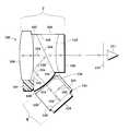
- FIG. 1is a perspective, partially cut-away view of a headset being worn by a viewer or user according to one embodiment of the present invention
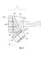
- FIG. 2is a side cross-sectional schematic view of an eyepiece according to one embodiment of the invention.
- FIG. 3is a side cross-sectional schematic view of the eyepiece of FIG. 2 showing light paths for axial and non-axial rays;
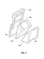
- FIG. 4is an exploded perspective view of a portion of the eyepiece of FIG. 2 .
- one embodiment of the present inventionis as a binocular display screen headset 5 configured to be worn on the head of a user or viewer 6 .
- the headset 5has a pair of small-area color displays 100 disposed within the headset.
- the displaysinclude LCoS panels available from Zight Corporation.
- Each of the displayshas a display panel (not shown) positioned behind an eyepiece 7 , shown in more detail in FIGS. 3 and 4, that is directly in front of a respective eye of the user so that each eye views a single one of the displays.
- the pixellated areas of each of the display panelsis rectangular, 9.6 mm wide and 7.2 mm high.
- the headsetis configured to fit comfortably against the face of the user with or without eyeglasses between the user and the headset eyepieces.
- Each of the displays 100includes a lighting apparatus 8 , shown in more detail in FIG. 2, to illuminate the display panel.
- the headsetis coupled through a cable 12 to a display driver 14 .
- the display driverreceives video signals through a port 16 and power through a power connector 18 and converts the video signals into a form suitable for driving the displays.
- the video signalscan be from a television, computer, video player or any other video or data source.
- the videocan be for single or for stereovision in which the two displays project different images to simulate perspective.
- the headsetcan be a monocular headset with a single display, eyepiece, and lighting apparatus.
- FIG. 2is a schematic side view of a first embodiment 100 of a compact, light-weight optical imaging system according to the invention.
- the optical imaging system 100is suitable for use in virtual displays and other types of miniature displays having similar performance requirements. In one embodiment, two such displays are placed side-by-side in a wearable headset as shown in FIG. 1, so that one display is oriented in front of each eye of the wearer.
- the optical imaging systemincludes an eyepiece portion 7 and a lighting apparatus or frontlight portion 8 .
- the eyepiece portionhas a first prism 102 , and a second prism 104 cemented to the first prism with optical cement to form an optical beam splitter.
- a converging optical element 136is formed on a surface of the first prism to act as a field lens for the display light.
- a diverging transmissive element 106is formed on a surface of the second prism as a diffractive optical element.
- the negative power optical element 106gives the eyepiece portion a long back focal length according to retro focus principles.
- Either elementcan also be provided as a separate lens adjacent the respective prism.
- a converging reflective element 108for example a Mangin mirror, is opposite and facing the diverging transmissive element 106 , spaced from a side of the first prism.
- the Mangin mirrormay include a diffractive optical surface on either its reflective or transmissive surface to perform the aberration correction functions of the negative power element 106 .
- the optical imaging system 100receives light from an object located at an image plane 120 and forms a non-inverted, enlarged, virtual image of the display that can be perceived by a user's eye 121 located at or near an exit pupil 122 .
- the optical imaging systemcan be configured to locate the virtual image at any predetermined distance from the exit pupil.
- the projected virtual imageis located 2 m from the exit pupil with a size of 1040 mm by 780 mm.
- the eye reliefis 25 mm.
- the illustrated optical systemprovides a short effective focal length of, for example, 18.3 mm with a very large aperture of f/1.3 in the horizontal and f/2.7 in the vertical.
- the short effective focal lengthpermits a very wide field of view of about 36 degrees even with small displays.
- the large aperturepermits a large exit pupil especially in the horizontal of about 12 mm, which allows the display to be used without adjustment by viewers with very different interpupillary distances.
- the exit pupil size in the vertical dimensionis about 6 mm. This superior performance is achieved using the configuration described in more detail below.
- the first prism 102has a substantially triangular cross-section in the plane of the drawing, and includes a second face 132 facing the Mangin mirror. This face is flat in the illustrated embodiment and can have an anti-reflective (AR) coating.
- the prismhas a third substantially flat face 134 facing the second prism. This face, or alternatively, the complementary face of the second prism, is coated with a semi-reflective coating layer 138 that is not sensitive to polarization.
- a semi-reflective coating layer 138that is not sensitive to polarization.
- birefringencewill vary non-uniformly through the prism material.
- the birefringencecreates non-uniform polarization variations throughout the prism.
- a conventional beam splitterreflects and transmits light differently depending on the polarization state. Accordingly, such a conventional beam splitter will convert the variations in polarization over the image to a variation in brightness which can easily be seen by the viewer. Accordingly, with plastic prisms, it is preferred that the semi-reflective coating reflect approximately half of the light and transmit approximately half of the light without any substantial sensitivity to the polarization of the light.
- a metal-dielectric-metal coatingcan be used to accomplish such a half-mirror.
- One such suitable coatingis ZnS 39 nm, Ag 23 nm, ZnS 81 nm.
- TiO 2is substituted for the ZnS.
- the semi-reflective layer 138can be deposited on the face of either prism by a suitable deposition process as is well-known in the art. Such a coating will reflect and transmit nearly equal portions of light without regard to polarization or wavelength throughout the visible spectrum (450 nm-650 nm).
- R avg *T avg22% to 24%, where R avg is the average reflectance and T avg is the average transmissivity.
- the sensitivity to polarizationcan be measured by comparing the transmissivity of S-polarized light Ts to the transmissivity of P-polarized light T P . The difference is less than 5% with the coating described above. Similarly the difference between the reflectance of S and P-polarized light
- the semi-reflecting coating layercan be in the form of a polarizing beamsplitting layer or film or it can be some other type of half-mirror.
- the first prismhas a first face 136 facing the image plane.
- the first facehas a convex surface that forms a field lens to converge divergent rays of the image plane light as it enters the first prism.
- the field lensserves to reduce the effective focal length and to control the pupil image location and quality.
- the field lensmay be formed on the prism surface as shown in FIG. 2 or it may be provided as a separate optical element cemented to or adjacent to a curved or flat face of the first prism.
- the display size at the image planeis 9.6 mm by 7.2 mm and the back focal length of the eyepiece portion of the optical system is about 6 mm in air.
- the included angle of the first prism between the Mangin mirror face 132 and the third face facing the second prism 104is about 25 degrees.
- the included angle between the third prism face 134 and the image plane face 136is about 105 degrees and the third included angle between the image plane face and the Mangin mirror face is about 50 degrees.
- the corner of the prism between the Mangin mirror face and the third facehas been truncated to reduce the overall size of the prism.
- the cornercan be left with the prism if desired.
- the specific anglescan be adapted to fit particular size and shape constraints.
- One important optical constraintis to provide total internal reflection (TIR) for light traveling from the display toward the Mangin mirror face of the prism 132 .
- the second prism 104also has a substantially triangular cross-section in the plane of the drawing and includes a first face 142 facing the exit pupil 122 .
- a diverging transmissive element 106is applied to this exit pupil face.
- the second prismhas a second substantially flat face 144 facing the first prism, and a third substantially flat face 146 that is not optically functional facing away from the image plane.
- the included angle between the exit pupil face 142 and the first prism face 144 of the second prismis substantially 25 degrees in order to complement the corresponding angle of the first prism. As can be seen from the drawings, this corner has also been truncated to reduce the size of the optical system. The included angles between the other faces are not important.
- the exit pupil face 142is arranged to be perpendicular to the optical axis of the diffractive optical element 106 and the third non-functional face is arranged to be parallel to this optical axis, although its particular shape and orientation are not important.
- the specific anglescan be adapted to fit particular size and shape constraints in concert with the first prism.
- the second face 144 of the second prism 104is cemented to the third face 134 of the first prism 102 with an appropriate optical cement and a metal-dielectric-metal coating to form an optical beam splitter that is not polarization dependent.
- the two facesare oriented so that the Mangin mirror face of the first prism 132 is opposite and substantially parallel to the exit pupil face 142 of the second prism.
- the two prismscan be made of optical quality molded polystyrene with an index of refraction of approximately 1.590 available, for example, as Styron 685D from Dow Chemical or polystyrene G9504 from A & M Polystyrene of Japan.
- the polystyrenecontains no blue additives, ultraviolet light inhibitors or release agents in order to reduce hazing.
- the prismscan be made of polycarbonate or other high index optical plastics or of optical glass such as type BK7 glass from Schott Glass Technologies. This glass has a refractive index of 1.520.
- Polystyrenesubstantially reduces the weight and mass-production cost compared with a glass prism, and also allows the diffractive optical element 106 to be molded integrally as part of the second prism.
- the higher refractive index of the polystyreneallows more freedom in choosing prism angles while maintaining total internal reflection on the Mangin mirror face of the first prism.
- Glassmay provide a sharper brighter image in certain applications and will preserve polarization when appropriate.
- the choice of materialsis not critical to the invention nor is the specific optical index of refraction.
- Both prismscan be glass prisms, both prisms can be plastic prisms, or a mixture of a glass prism and a plastic prism can be used.
- the rear element 108is a converging reflective element, for example a Mangin mirror.
- itis formed of a bi-convex, plano-convex or meniscus lens that has a reflective coating such as protected silver on the convex face opposite the prism to form the reflective surface 140 .
- a suitable coatingwould be a Al 2 O 3 —Ag—Al 2 O 3 coating.
- itis constructed from acrylic plastic with an index of refraction of about 1.492. Such optical acrylics are commonly available as is well-known in the art. It can also have an anti-reflection coating such as a single quarter-wave layer of M g F 2 or other conventional dielectric multilayer films on the convex face facing the prism.
- the refractive surface of the Mangin mirrorhelps to reduce aberrations including chromatic aberrations.
- the rear elementcan be formed of single or bi-aspheric surfaces to minimize spherical and other aberrations.
- the rear elementmay be constructed of a mirror and a separate lens such that the combination has positive power.
- the mirrorcan be flat or curved.
- the rear elementmay be constructed as a mirror only.
- the rear element 108is mounted to a frame 107 (see FIG. 4) that is, in turn, mounted to the first prism 102 .
- the framemaintains an air space between the rear element and the first prism to allow total internal reflection off the face of the prism facing the rear element.
- the rear elementcan have mechanical features which allow it to be mounted to the first prism without the need for the frame.
- the prism, rear element, and framecan be constructed of a single piece which does not require assembly.
- the optical axis of the rear elementis centered on the optical axis of the front element 106 , the diverging diffractive optical element.
- the rear element, the front element, and the field lenscollectively constitute a three-element magnifying system that forms the non-inverted, wide field-of-view virtual image of an object located at the image plane 120 .
- the front elementcan be a conventional spherical or aspherical compound lens to reduce chromatic aberration and to focus the image.
- the Mangin mirroris formed from an aspheric, but rotationally symmetric substrate on both surfaces in order to minimize aberrations.
- the front element 106is formed from a diffractive kinoform structure embedded in an aspheric substrate.
- a diffractive optical elementcan be smaller and lighter than an equivalent conventional lens, and cheaper to mass-produce.
- the diffractive optical element 106is designed to provide the required dispersion and wavefront characteristics so as to correct chromatic aberration, especially lateral color aberration, and residual spherical aberration of the rear element.
- the diffractive optical element 106can be fabricated as a flexible or rigid thin-film element that is attached to the exit pupil face of the second prism 104 either mechanically or by using a suitable index-matched adhesive. To simplify assembly with a molded prism, the topological features of the diffractive optical element may be defined in the mold. This reduces the number of parts and eliminates the need to perform any alignment between the front element and the second prism because it is one monolithic piece.
- the diffractive optical elementlike the Mangin mirror and the field lens is based on a rotationally symmetric aspherical substrate.
- the diffractive optical elementcan have a minimum pitch of 20 ⁇ m and a monotonic phase to significantly reduce manufacturing difficulty.
- the image plane 120is produced by a display 119 .
- the displaycan be reflective such as an LCoS display, transmissive, such as a liquid crystal display or emissive such as a cathode ray tube, LED (light emitting diode), or OLED (organic light emitting diode) display.
- the displayis a reflective display illuminated by a polarized light source 124 through a pre-polarizing film 125 , and a polarizing beam splitter cube 126 as is well-known in the art.
- the polarizing beamsplitting cubemay include a polymer film stack, wire grid polarizer, or dielectric coating stack at the diagonal beamsplitting surface.
- the imageBefore entering the eyepiece portion, the image is passed through a polarizing analyzer 128 , such as an iodine-based PVA (poly-vinyl alcohol) film.
- a polarizing analyzer 128such as an iodine-based PVA (poly-vinyl alcohol) film.
- the polarizing beam splittermay be replaced by a half mirror.
- the single light source 124can be made up of multiple LEDs adjacent to one another of a single or of multiple colors. Instead of LEDs, laser diodes, cold cathode or field emitter cathodoluminescent sources, incandescent, and fluorescent lamps together with a switchable color filter, or any other appropriate light source can be used. Collimating lenses, diffusers, and collectors can also be used to control the nature of the illumination.
- the particular design of the light sourceis not essential to the invention.
- the light sourceshould include a polarizing element 125 similar to the analyzer 128 to optimize the contrast performance of the cube.
- a more compact frontlight that produces diverging rays from the displayis shown in co-pending patent application Ser. No. 09/872,073, filed on the same day as the present application, entitled Compact Near-Eye Illumination System and assigned to the same assignee as the present application, the disclosure of which is incorporated fully by reference herein.
- This frontlightallows an image of the aperture stop of the light source to be formed at the eyepiece pupil. It also provides a folded optical path length from the light source to the image plane which is not telecentric. To the eyepiece, the frontlight behaves as a plate of glass with parallel faces.
- the effective focal length of the eyepieceis made short in order to maximize the field of view for the viewer.
- the displayis 9.60 by 7.2 mm and the effective focal length is 18.3 mm.
- the back focal length of an eyepiece for the present applicationbut without attention to maximizing the back focal length would typically be 1 or 2 mm.
- the back focal lengthis increased to accommodate the frontlight for the reflective display.
- the back focal length of the eyepiece systemis approximately 6 mm in air. This is accomplished using a retrofocus design with a diverging front element 106 and appropriate powers on the field lens and Mangin mirror. Providing diverging rays from the image plane of the display complements the design.
- the field lens 136positions the entrance pupil close to the display.
- the frontlight shown in the co-pending patent application Compact Near-Eye Illumination Systemprovides just such a diverging image by forming an image of its aperture stop at the entrance pupil of the eyepiece. Improved optical performance is obtained by matching the entrance and exit pupil so that the entrance pupil of the eyepiece is coincident to the exit pupil of the frontlight.
- the imagecan be made to be diverging using other displays and other optical systems.
- An important function of the field lensis to position the entrance pupil of the eyepiece coincident with the exit pupil of the frontlight.
- FIG. 2also shows a tracing of a single central ray through the eyepiece.
- Light 150pre-polarized by the polarizer 125 , emanates from the light source 124 as S-polarized light. This light is reflected by the beam splitter cube to the display 119 and is either reflected as P-polarized light 152 back to the beam splitter cube or as S-polarized light.
- the S-polarized light from the displayis reflected by the beamsplitting layer and directed at the light source 124 .
- the P-polarized light 154passes through the beam splitter layer to render the display to the viewer. From the cube, it propagates through the polarizing “clean-up” analyzer 128 and the field lens 136 into the first eyepiece prism.
- the field lensis a converging element which reduces the divergence without eliminating it.
- the light pathis folded by total internal reflection (for high efficiency) off the rear face 132 of the prism and folded by the partially reflecting coating 138 back to the rear face 132 of the prism and then to the rear element 108 of the eyepiece.
- Roughly half of the display light within the first prismis not reflected by the semi-reflecting layer but is transmitted through it.
- This lightenters the second prism 104 at an angle to the optical axis of that prism. It then passes across the optical axis and exits the system though the prism's other flat surface 104 or is absorbed by blackened areas of the eyepiece to control stray light.
- the folded light pathaligns the display light with the optical axis between the rear element 108 and the front element 106 of the eyepiece.
- the display light directed to the rear element by the prismis reflected off the rear element and directed along the optical axis through the semi-reflective layer 138 and the front element 106 to the exit pupil 122 and the viewer 121 .
- the filtermay be neutral or it may be colored to balance the primary colors of the display.
- the filtercan be integrated with analyzer 128 , if desired.
- the ghost lightcan be eliminated almost completely by introducing a quarter wave retarder between the eyepiece and the frontlight.
- the light reflected from the beam splitter in the eye-piecethen undergoes two traversals of the retarder and gets absorbed by the analyzer before returning to the display.
- the reflectivity of the mirrored surface of the rear element 140is maximized in order to maximize the brightness of the image projected to the user's eye 121 located near the exit pupil 122 .
- a reflectivity as high as 95%-98%may be used.
- the reflective surfaceis encapsulated with a suitable sealant to protect the silvered reflective surface.
- the reflectivity of the reflective surface 140can be made substantially less than 100%, e.g., about 50%, to allow light from the user's environment to pass through the rear element.
- the rear element and the front elementin that case collectively form an image of the user's environment as well as an image of the display.
- An auxiliary lens systemmay be added after the Mangin mirror to improve the viewer's perception of the outside world.
- the effective focal length of the eyepiece system looking through the Mangin mirrorwould be about 1.6 m, providing a small magnification. Distortion would be low, depending on the particular design, typically less than 10%.
- the auxiliary lens system(not shown) can be added behind the Mangin mirror to compensate for the magnification and distortion as is well-known in the art.
- FIG. 3shows a ray tracing for axial and off-axis rays reflected off the display 119 at the image plane 120 .
- the imageis folded twice in the first prism and then focused on the exit pupil.
- FIG. 4shows an exploded perspective view of the first 102 and second 104 prisms, the rear element 108 , and the mounting bracket 107 .
- the optical converging and diverging surfaces of each pieceare more easily seen in this drawing.
- the display 119produces a rectangular image with an aspect ratio of 4:3 similar to that of a typical television or computer monitor.
- the optical surfacesare rectangular with an aspect ratio determined by the aspect ratio of the display (4:3) and the aspect ratio of the exit pupil (2:1).
- the piecesare preferably molded in shapes that facilitate optical alignment and are cemented together. For surfaces that do not require optical cement for optical coupling, the parts may use a snap fit as a connection.
- the prisms, the field lens, the front element, and the rear elementall be coated with an antireflective coating on all surfaces that are not described herein as having another coating. It is also preferred that the field lens, front element, and rear element have rotationally symmetric, aspherical optical surfaces as described below.
- the front element 106is a diffractive optical element, defined by the following aspherical coefficients, based on an ashperical formulation as follows:
- the diffractive kinoform of the front element 106is defined by a diffractive phase polynomial as follows:
- the rear element 108is a Mangin-type mirror with a reflective side and a transmissive side. Both surfaces are rotationally symmetric, aspherical surfaces as defined above. The surfaces are defined by the following coefficients:
- the field lens surface 136is defined by the following aspherical coordinates:
- the apparatus described hereinare equally applicable to any type of eyepiece for a small display whether for one eye or both, in which compactness and a wide field of view and are desired.
- the techniques described hereinare thought to be useful in connection with compact computer and data device displays, monocular headsets, digital camera viewfinders, camcorder viewfinders, internet appliance viewers, mobile communicator viewers and entertainments headsets for video and game players.
Landscapes
- Physics & Mathematics (AREA)
- General Physics & Mathematics (AREA)
- Optics & Photonics (AREA)
Abstract
Description
| α1= 0.00 | α2= −1.21 × 10⁻⁶ | α3= 1.03 × 10⁻⁷ | α4= 2.88 × 10⁻⁹ |
| α5= −7.34 × | α6= 6.96 × 10⁻¹³ | α7= −2.62 × 10⁻¹⁵ | α8= 2.41 × 10⁻¹⁸ |
| 10−11 | |||
| α1= 0.00 | α2= 9.40 × 10⁻⁷ | α3= −2.12 × 10⁻⁸ | α4= −4.43 × 10⁻¹¹ |
| α5= −9.22 × | α6= 0.00 | α7= 0.00 | α8= 0.00 |
| 10−14 | |||
| α1= 0.00 | α2= 2.99 × 10⁻⁶ | α3= 4.22 × 10⁻¹⁰ | α4= −2.76 × 10⁻¹¹ |
| α5= −2.16 × | α6= 0.00 | α7= 0.00 | α8= 0.00 |
| 10−14 | |||

| α1= 0.0015 | α2= −9.04 × | α3= −3.83 × 10⁻⁷ | α4= 2.58 × 10⁻⁹ |
| 10−6 | |||
| α5=9.95 × 10⁻¹² | α6= −6.47 × | α7= −5.37 × 10⁻¹⁶ | α8= 2.55 × 10⁻¹⁸ |
| 10−14 | |||
Claims (27)
Priority Applications (2)
| Application Number | Priority Date | Filing Date | Title |
|---|---|---|---|
| US09/872,111US6563648B2 (en) | 2000-10-20 | 2001-06-01 | Compact wide field of view imaging system |
| PCT/US2002/017549WO2002099508A1 (en) | 2001-06-01 | 2002-05-24 | Compact wide field of view imaging system |
Applications Claiming Priority (2)
| Application Number | Priority Date | Filing Date | Title |
|---|---|---|---|
| US24218900P | 2000-10-20 | 2000-10-20 | |
| US09/872,111US6563648B2 (en) | 2000-10-20 | 2001-06-01 | Compact wide field of view imaging system |
Publications (2)
| Publication Number | Publication Date |
|---|---|
| US20030030912A1 US20030030912A1 (en) | 2003-02-13 |
| US6563648B2true US6563648B2 (en) | 2003-05-13 |
Family
ID=25358858
Family Applications (1)
| Application Number | Title | Priority Date | Filing Date |
|---|---|---|---|
| US09/872,111Expired - LifetimeUS6563648B2 (en) | 2000-10-20 | 2001-06-01 | Compact wide field of view imaging system |
Country Status (2)
| Country | Link |
|---|---|
| US (1) | US6563648B2 (en) |
| WO (1) | WO2002099508A1 (en) |
Cited By (118)
| Publication number | Priority date | Publication date | Assignee | Title |
|---|---|---|---|---|
| US20020167733A1 (en)* | 2001-04-27 | 2002-11-14 | Wouter Roest | Compact display device |
| US20030020006A1 (en)* | 2001-07-24 | 2003-01-30 | Janeczko Donald John | Planar diffractive relay |
| US20040125449A1 (en)* | 2002-12-30 | 2004-07-01 | Sales Tasso R. | Grid polarizer with suppressed reflectivity |
| US20040174614A1 (en)* | 2003-01-02 | 2004-09-09 | Hovanky Thao D. | Systems and methods for actuating lens assemblies |
| US20040174348A1 (en)* | 2003-02-19 | 2004-09-09 | Yair David | Chromatic planar optic display system |
| US20040178970A1 (en)* | 2002-12-10 | 2004-09-16 | Ingineo Sas | Face-mounted apparatus having spectacles and a video display integrated into the spectacles |
| US20040183907A1 (en)* | 2003-01-02 | 2004-09-23 | Hovanky Thao D. | Optical block assembly |
| US20050286135A1 (en)* | 2004-02-04 | 2005-12-29 | Paul Weissman | Compact electronic viewfinder |
| USD523005S1 (en)* | 2003-12-31 | 2006-06-13 | Eyeneo Sas | Video display control unit comprising charging base and control unit box |
| USD531998S1 (en)* | 2003-12-31 | 2006-11-14 | Eyeneo Sas | Video display control unit |
| US20070058119A1 (en)* | 2005-09-12 | 2007-03-15 | Fuji Photo Film Co., Ltd. | Liquid crystal display and light-emitting element |
| US20090027772A1 (en)* | 2007-07-26 | 2009-01-29 | Real D | Head-Mounted Single Panel Stereoscopic Display |
| WO2007139900A3 (en)* | 2006-05-26 | 2009-04-23 | Creative Display Systems Llc | Wide field of view, compact collimating apparatus |
| US20090128902A1 (en)* | 2005-11-03 | 2009-05-21 | Yehuda Niv | Binocular Optical Relay Device |
| US20090141503A1 (en)* | 2007-11-30 | 2009-06-04 | 3M Innovative Properties Company | Optical element having a toric surface and method of making |
| US20100208372A1 (en)* | 2009-02-19 | 2010-08-19 | Drs Sensors & Targeting Systems, Inc. | Compact Objective Lens Assembly for Simultaneously Imaging Multiple Spectral Bands |
| US20110037951A1 (en)* | 2008-01-22 | 2011-02-17 | Hong Hua | Head-mounted projection display using reflective microdisplays |
| US8867131B1 (en)* | 2012-03-06 | 2014-10-21 | Google Inc. | Hybrid polarizing beam splitter |
| CN104755994A (en)* | 2013-07-04 | 2015-07-01 | 索尼公司 | Display device |
| US9239453B2 (en) | 2009-04-20 | 2016-01-19 | Beijing Institute Of Technology | Optical see-through free-form head-mounted display |
| US9244277B2 (en) | 2010-04-30 | 2016-01-26 | The Arizona Board Of Regents On Behalf Of The University Of Arizona | Wide angle and high resolution tiled head-mounted display device |
| USD771075S1 (en)* | 2012-11-30 | 2016-11-08 | Axell Corporation | Display screen with graphical user interface |
| US9507150B1 (en) | 2011-09-30 | 2016-11-29 | Rockwell Collins, Inc. | Head up display (HUD) using a bent waveguide assembly |
| US9519089B1 (en) | 2014-01-30 | 2016-12-13 | Rockwell Collins, Inc. | High performance volume phase gratings |
| US9523852B1 (en) | 2012-03-28 | 2016-12-20 | Rockwell Collins, Inc. | Micro collimator system and method for a head up display (HUD) |
| US9679367B1 (en) | 2013-04-17 | 2017-06-13 | Rockwell Collins, Inc. | HUD system and method with dynamic light exclusion |
| US9715067B1 (en)* | 2011-09-30 | 2017-07-25 | Rockwell Collins, Inc. | Ultra-compact HUD utilizing waveguide pupil expander with surface relief gratings in high refractive index materials |
| US9715110B1 (en) | 2014-09-25 | 2017-07-25 | Rockwell Collins, Inc. | Automotive head up display (HUD) |
| US9720232B2 (en) | 2012-01-24 | 2017-08-01 | The Arizona Board Of Regents On Behalf Of The University Of Arizona | Compact eye-tracked head-mounted display |
| US9766465B1 (en) | 2014-03-25 | 2017-09-19 | Rockwell Collins, Inc. | Near eye display system and method for display enhancement or redundancy |
| US9791703B1 (en) | 2016-04-13 | 2017-10-17 | Microsoft Technology Licensing, Llc | Waveguides with extended field of view |
| US9874760B2 (en) | 2012-10-18 | 2018-01-23 | Arizona Board Of Regents On Behalf Of The University Of Arizona | Stereoscopic displays with addressable focus cues |
| US9933684B2 (en) | 2012-11-16 | 2018-04-03 | Rockwell Collins, Inc. | Transparent waveguide display providing upper and lower fields of view having a specific light output aperture configuration |
| US9977247B1 (en) | 2011-09-30 | 2018-05-22 | Rockwell Collins, Inc. | System for and method of displaying information without need for a combiner alignment detector |
| US10007115B2 (en)* | 2015-08-12 | 2018-06-26 | Daqri, Llc | Placement of a computer generated display with focal plane at finite distance using optical devices and a see-through head-mounted display incorporating the same |
| US10067347B2 (en) | 2016-04-13 | 2018-09-04 | Microsoft Technology Licensing, Llc | Waveguides with improved intensity distributions |
| US10088675B1 (en) | 2015-05-18 | 2018-10-02 | Rockwell Collins, Inc. | Turning light pipe for a pupil expansion system and method |
| US10089516B2 (en) | 2013-07-31 | 2018-10-02 | Digilens, Inc. | Method and apparatus for contact image sensing |
| US10095045B2 (en) | 2016-09-12 | 2018-10-09 | Microsoft Technology Licensing, Llc | Waveguide comprising a bragg polarization grating |
| US10108010B2 (en) | 2015-06-29 | 2018-10-23 | Rockwell Collins, Inc. | System for and method of integrating head up displays and head down displays |
| US10126552B2 (en) | 2015-05-18 | 2018-11-13 | Rockwell Collins, Inc. | Micro collimator system and method for a head up display (HUD) |
| US10145533B2 (en) | 2005-11-11 | 2018-12-04 | Digilens, Inc. | Compact holographic illumination device |
| US10156681B2 (en) | 2015-02-12 | 2018-12-18 | Digilens Inc. | Waveguide grating device |
| US10176961B2 (en) | 2015-02-09 | 2019-01-08 | The Arizona Board Of Regents On Behalf Of The University Of Arizona | Small portable night vision system |
| US10185154B2 (en) | 2011-04-07 | 2019-01-22 | Digilens, Inc. | Laser despeckler based on angular diversity |
| US10209517B2 (en) | 2013-05-20 | 2019-02-19 | Digilens, Inc. | Holographic waveguide eye tracker |
| US10216061B2 (en) | 2012-01-06 | 2019-02-26 | Digilens, Inc. | Contact image sensor using switchable bragg gratings |
| US10234696B2 (en) | 2007-07-26 | 2019-03-19 | Digilens, Inc. | Optical apparatus for recording a holographic device and method of recording |
| US10241330B2 (en) | 2014-09-19 | 2019-03-26 | Digilens, Inc. | Method and apparatus for generating input images for holographic waveguide displays |
| US10247943B1 (en) | 2015-05-18 | 2019-04-02 | Rockwell Collins, Inc. | Head up display (HUD) using a light pipe |
| US10268040B2 (en) | 2016-04-01 | 2019-04-23 | Coretronic Corporation | Display box |
| US10295824B2 (en) | 2017-01-26 | 2019-05-21 | Rockwell Collins, Inc. | Head up display with an angled light pipe |
| US10330777B2 (en) | 2015-01-20 | 2019-06-25 | Digilens Inc. | Holographic waveguide lidar |
| US10353202B2 (en)* | 2016-06-09 | 2019-07-16 | Microsoft Technology Licensing, Llc | Wrapped waveguide with large field of view |
| US10359736B2 (en) | 2014-08-08 | 2019-07-23 | Digilens Inc. | Method for holographic mastering and replication |
| US10423222B2 (en) | 2014-09-26 | 2019-09-24 | Digilens Inc. | Holographic waveguide optical tracker |
| US10422976B2 (en) | 2016-02-26 | 2019-09-24 | Samsung Electronics Co., Ltd. | Aberration corrected optical system for near-eye displays |
| US10437051B2 (en) | 2012-05-11 | 2019-10-08 | Digilens Inc. | Apparatus for eye tracking |
| US10437064B2 (en) | 2015-01-12 | 2019-10-08 | Digilens Inc. | Environmentally isolated waveguide display |
| US10459145B2 (en) | 2015-03-16 | 2019-10-29 | Digilens Inc. | Waveguide device incorporating a light pipe |
| US10469833B2 (en) | 2014-03-05 | 2019-11-05 | The Arizona Board Of Regents On Behalf Of The University Of Arizona | Wearable 3D augmented reality display with variable focus and/or object recognition |
| US10488666B2 (en) | 2018-02-10 | 2019-11-26 | Daqri, Llc | Optical waveguide devices, methods and systems incorporating same |
| US10509241B1 (en) | 2009-09-30 | 2019-12-17 | Rockwell Collins, Inc. | Optical displays |
| US10545346B2 (en) | 2017-01-05 | 2020-01-28 | Digilens Inc. | Wearable heads up displays |
| US10560688B2 (en) | 2017-05-22 | 2020-02-11 | Microsoft Technology Licensing, Llc | Display device system with non-telecentric imaging to prevent ghost images |
| US10591756B2 (en) | 2015-03-31 | 2020-03-17 | Digilens Inc. | Method and apparatus for contact image sensing |
| US10598932B1 (en) | 2016-01-06 | 2020-03-24 | Rockwell Collins, Inc. | Head up display for integrating views of conformally mapped symbols and a fixed image source |
| US10642058B2 (en) | 2011-08-24 | 2020-05-05 | Digilens Inc. | Wearable data display |
| US10649209B2 (en) | 2016-07-08 | 2020-05-12 | Daqri Llc | Optical combiner apparatus |
| US10670876B2 (en) | 2011-08-24 | 2020-06-02 | Digilens Inc. | Waveguide laser illuminator incorporating a despeckler |
| US10678053B2 (en) | 2009-04-27 | 2020-06-09 | Digilens Inc. | Diffractive projection apparatus |
| US10690915B2 (en) | 2012-04-25 | 2020-06-23 | Rockwell Collins, Inc. | Holographic wide angle display |
| US10690916B2 (en) | 2015-10-05 | 2020-06-23 | Digilens Inc. | Apparatus for providing waveguide displays with two-dimensional pupil expansion |
| US10690851B2 (en) | 2018-03-16 | 2020-06-23 | Digilens Inc. | Holographic waveguides incorporating birefringence control and methods for their fabrication |
| US10732407B1 (en) | 2014-01-10 | 2020-08-04 | Rockwell Collins, Inc. | Near eye head up display system and method with fixed combiner |
| US10732569B2 (en) | 2018-01-08 | 2020-08-04 | Digilens Inc. | Systems and methods for high-throughput recording of holographic gratings in waveguide cells |
| US10739578B2 (en) | 2016-08-12 | 2020-08-11 | The Arizona Board Of Regents On Behalf Of The University Of Arizona | High-resolution freeform eyepiece design with a large exit pupil |
| US10795160B1 (en) | 2014-09-25 | 2020-10-06 | Rockwell Collins, Inc. | Systems for and methods of using fold gratings for dual axis expansion |
| EP3722858A1 (en)* | 2016-07-22 | 2020-10-14 | Swarovski-Optik KG. | Long range optical device with a reticle |
| US10859768B2 (en) | 2016-03-24 | 2020-12-08 | Digilens Inc. | Method and apparatus for providing a polarization selective holographic waveguide device |
| US10890707B2 (en) | 2016-04-11 | 2021-01-12 | Digilens Inc. | Holographic waveguide apparatus for structured light projection |
| US10914950B2 (en) | 2018-01-08 | 2021-02-09 | Digilens Inc. | Waveguide architectures and related methods of manufacturing |
| US10942430B2 (en) | 2017-10-16 | 2021-03-09 | Digilens Inc. | Systems and methods for multiplying the image resolution of a pixelated display |
| US10983340B2 (en) | 2016-02-04 | 2021-04-20 | Digilens Inc. | Holographic waveguide optical tracker |
| US11079596B2 (en) | 2009-09-14 | 2021-08-03 | The Arizona Board Of Regents On Behalf Of The University Of Arizona | 3-dimensional electro-optical see-through displays |
| US11125993B2 (en) | 2018-12-10 | 2021-09-21 | Facebook Technologies, Llc | Optical hyperfocal reflective systems and methods, and augmented reality and/or virtual reality displays incorporating same |
| US11204540B2 (en) | 2009-10-09 | 2021-12-21 | Digilens Inc. | Diffractive waveguide providing a retinal image |
| US11221494B2 (en) | 2018-12-10 | 2022-01-11 | Facebook Technologies, Llc | Adaptive viewport optical display systems and methods |
| US11275436B2 (en) | 2017-01-11 | 2022-03-15 | Rpx Corporation | Interface-based modeling and design of three dimensional spaces using two dimensional representations |
| US11300795B1 (en) | 2009-09-30 | 2022-04-12 | Digilens Inc. | Systems for and methods of using fold gratings coordinated with output couplers for dual axis expansion |
| US11307432B2 (en) | 2014-08-08 | 2022-04-19 | Digilens Inc. | Waveguide laser illuminator incorporating a Despeckler |
| US11314084B1 (en) | 2011-09-30 | 2022-04-26 | Rockwell Collins, Inc. | Waveguide combiner system and method with less susceptibility to glare |
| US11320571B2 (en) | 2012-11-16 | 2022-05-03 | Rockwell Collins, Inc. | Transparent waveguide display providing upper and lower fields of view with uniform light extraction |
| US11366316B2 (en) | 2015-05-18 | 2022-06-21 | Rockwell Collins, Inc. | Head up display (HUD) using a light pipe |
| US11378732B2 (en) | 2019-03-12 | 2022-07-05 | DigLens Inc. | Holographic waveguide backlight and related methods of manufacturing |
| US11402801B2 (en) | 2018-07-25 | 2022-08-02 | Digilens Inc. | Systems and methods for fabricating a multilayer optical structure |
| US11442222B2 (en) | 2019-08-29 | 2022-09-13 | Digilens Inc. | Evacuated gratings and methods of manufacturing |
| US11454783B2 (en) | 2018-04-25 | 2022-09-27 | Samsung Electronics Co., Ltd. | Tiled triplet lenses providing a wide field of view |
| US11480788B2 (en) | 2015-01-12 | 2022-10-25 | Digilens Inc. | Light field displays incorporating holographic waveguides |
| US11513350B2 (en) | 2016-12-02 | 2022-11-29 | Digilens Inc. | Waveguide device with uniform output illumination |
| US11546575B2 (en) | 2018-03-22 | 2023-01-03 | Arizona Board Of Regents On Behalf Of The University Of Arizona | Methods of rendering light field images for integral-imaging-based light field display |
| US11543594B2 (en) | 2019-02-15 | 2023-01-03 | Digilens Inc. | Methods and apparatuses for providing a holographic waveguide display using integrated gratings |
| US11662513B2 (en) | 2019-01-09 | 2023-05-30 | Meta Platforms Technologies, Llc | Non-uniform sub-pupil reflectors and methods in optical waveguides for AR, HMD and HUD applications |
| US11681143B2 (en) | 2019-07-29 | 2023-06-20 | Digilens Inc. | Methods and apparatus for multiplying the image resolution and field-of-view of a pixelated display |
| US11726332B2 (en) | 2009-04-27 | 2023-08-15 | Digilens Inc. | Diffractive projection apparatus |
| US11747568B2 (en) | 2019-06-07 | 2023-09-05 | Digilens Inc. | Waveguides incorporating transmissive and reflective gratings and related methods of manufacturing |
| US11863730B2 (en) | 2021-12-07 | 2024-01-02 | Snap Inc. | Optical waveguide combiner systems and methods |
| US11927751B2 (en) | 2022-04-19 | 2024-03-12 | Sindarin, Inc. | Adjustable optical units for a wearable e-reader |
| US12044850B2 (en) | 2017-03-09 | 2024-07-23 | Arizona Board Of Regents On Behalf Of The University Of Arizona | Head-mounted light field display with integral imaging and waveguide prism |
| US12078802B2 (en) | 2017-03-09 | 2024-09-03 | Arizona Board Of Regents On Behalf Of The University Of Arizona | Head-mounted light field display with integral imaging and relay optics |
| US12092914B2 (en) | 2018-01-08 | 2024-09-17 | Digilens Inc. | Systems and methods for manufacturing waveguide cells |
| US12140764B2 (en) | 2019-02-15 | 2024-11-12 | Digilens Inc. | Wide angle waveguide display |
| US12158612B2 (en) | 2021-03-05 | 2024-12-03 | Digilens Inc. | Evacuated periodic structures and methods of manufacturing |
| US12210153B2 (en) | 2019-01-14 | 2025-01-28 | Digilens Inc. | Holographic waveguide display with light control layer |
| US12222499B2 (en) | 2020-12-21 | 2025-02-11 | Digilens Inc. | Eye glow suppression in waveguide based displays |
| US12306585B2 (en) | 2018-01-08 | 2025-05-20 | Digilens Inc. | Methods for fabricating optical waveguides |
| US12397477B2 (en) | 2019-02-05 | 2025-08-26 | Digilens Inc. | Methods for compensating for optical surface nonuniformity |
| US12399326B2 (en) | 2021-01-07 | 2025-08-26 | Digilens Inc. | Grating structures for color waveguides |
Families Citing this family (153)
| Publication number | Priority date | Publication date | Assignee | Title |
|---|---|---|---|---|
| US7158096B1 (en)* | 1999-06-21 | 2007-01-02 | The Microoptical Corporation | Compact, head-mountable display device with suspended eyepiece assembly |
| MXPA05009442A (en) | 2003-03-05 | 2005-11-23 | 3M Innovative Properties Co | Diffractive lens. |
| US7277641B1 (en) | 2003-05-06 | 2007-10-02 | Ball Aerospace & Technologies Corp. | Multiple access space communications optical system using a common telescope aperture |
| IL157838A (en)* | 2003-09-10 | 2013-05-30 | Yaakov Amitai | High brightness optical device |
| US20060018024A1 (en)* | 2004-07-23 | 2006-01-26 | Bryant Kyle R | Panoramic see-through optical device |
| US7668468B1 (en) | 2004-10-01 | 2010-02-23 | Ball Aerospace & Technologies Corp. | Numerous user laser communications optical system using chromatic waveplates and a common telescope aperture |
| US10073264B2 (en) | 2007-08-03 | 2018-09-11 | Lumus Ltd. | Substrate-guide optical device |
| FR2883078B1 (en)* | 2005-03-10 | 2008-02-22 | Essilor Int | OPTICAL IMAGER FOR REALIZING AN OPTICAL DISPLAY |
| JP2008070604A (en)* | 2006-09-14 | 2008-03-27 | Canon Inc | Image display device |
| JP4395802B2 (en)* | 2007-11-29 | 2010-01-13 | ソニー株式会社 | Image display device |
| KR100908909B1 (en) | 2007-11-30 | 2009-08-03 | 방주광학 주식회사 | Optical system of head mounted display |
| US9158116B1 (en) | 2014-04-25 | 2015-10-13 | Osterhout Group, Inc. | Temple and ear horn assembly for headworn computer |
| US9715112B2 (en) | 2014-01-21 | 2017-07-25 | Osterhout Group, Inc. | Suppression of stray light in head worn computing |
| US9400390B2 (en) | 2014-01-24 | 2016-07-26 | Osterhout Group, Inc. | Peripheral lighting for head worn computing |
| US9952664B2 (en) | 2014-01-21 | 2018-04-24 | Osterhout Group, Inc. | Eye imaging in head worn computing |
| US9298007B2 (en) | 2014-01-21 | 2016-03-29 | Osterhout Group, Inc. | Eye imaging in head worn computing |
| US9366867B2 (en) | 2014-07-08 | 2016-06-14 | Osterhout Group, Inc. | Optical systems for see-through displays |
| US20150277120A1 (en) | 2014-01-21 | 2015-10-01 | Osterhout Group, Inc. | Optical configurations for head worn computing |
| US9229233B2 (en) | 2014-02-11 | 2016-01-05 | Osterhout Group, Inc. | Micro Doppler presentations in head worn computing |
| US9965681B2 (en) | 2008-12-16 | 2018-05-08 | Osterhout Group, Inc. | Eye imaging in head worn computing |
| US20150205111A1 (en) | 2014-01-21 | 2015-07-23 | Osterhout Group, Inc. | Optical configurations for head worn computing |
| US20110214082A1 (en)* | 2010-02-28 | 2011-09-01 | Osterhout Group, Inc. | Projection triggering through an external marker in an augmented reality eyepiece |
| US20120249797A1 (en) | 2010-02-28 | 2012-10-04 | Osterhout Group, Inc. | Head-worn adaptive display |
| US9229227B2 (en) | 2010-02-28 | 2016-01-05 | Microsoft Technology Licensing, Llc | See-through near-eye display glasses with a light transmissive wedge shaped illumination system |
| US8488246B2 (en) | 2010-02-28 | 2013-07-16 | Osterhout Group, Inc. | See-through near-eye display glasses including a curved polarizing film in the image source, a partially reflective, partially transmitting optical element and an optically flat film |
| US9223134B2 (en) | 2010-02-28 | 2015-12-29 | Microsoft Technology Licensing, Llc | Optical imperfections in a light transmissive illumination system for see-through near-eye display glasses |
| US9129295B2 (en) | 2010-02-28 | 2015-09-08 | Microsoft Technology Licensing, Llc | See-through near-eye display glasses with a fast response photochromic film system for quick transition from dark to clear |
| US8467133B2 (en) | 2010-02-28 | 2013-06-18 | Osterhout Group, Inc. | See-through display with an optical assembly including a wedge-shaped illumination system |
| US10180572B2 (en) | 2010-02-28 | 2019-01-15 | Microsoft Technology Licensing, Llc | AR glasses with event and user action control of external applications |
| US9097890B2 (en) | 2010-02-28 | 2015-08-04 | Microsoft Technology Licensing, Llc | Grating in a light transmissive illumination system for see-through near-eye display glasses |
| US8477425B2 (en) | 2010-02-28 | 2013-07-02 | Osterhout Group, Inc. | See-through near-eye display glasses including a partially reflective, partially transmitting optical element |
| US9097891B2 (en) | 2010-02-28 | 2015-08-04 | Microsoft Technology Licensing, Llc | See-through near-eye display glasses including an auto-brightness control for the display brightness based on the brightness in the environment |
| WO2011106797A1 (en)* | 2010-02-28 | 2011-09-01 | Osterhout Group, Inc. | Projection triggering through an external marker in an augmented reality eyepiece |
| US8472120B2 (en) | 2010-02-28 | 2013-06-25 | Osterhout Group, Inc. | See-through near-eye display glasses with a small scale image source |
| US9285589B2 (en) | 2010-02-28 | 2016-03-15 | Microsoft Technology Licensing, Llc | AR glasses with event and sensor triggered control of AR eyepiece applications |
| US9341843B2 (en) | 2010-02-28 | 2016-05-17 | Microsoft Technology Licensing, Llc | See-through near-eye display glasses with a small scale image source |
| US8964298B2 (en) | 2010-02-28 | 2015-02-24 | Microsoft Corporation | Video display modification based on sensor input for a see-through near-to-eye display |
| US20110213664A1 (en)* | 2010-02-28 | 2011-09-01 | Osterhout Group, Inc. | Local advertising content on an interactive head-mounted eyepiece |
| US9128281B2 (en) | 2010-09-14 | 2015-09-08 | Microsoft Technology Licensing, Llc | Eyepiece with uniformly illuminated reflective display |
| US9091851B2 (en) | 2010-02-28 | 2015-07-28 | Microsoft Technology Licensing, Llc | Light control in head mounted displays |
| US9759917B2 (en) | 2010-02-28 | 2017-09-12 | Microsoft Technology Licensing, Llc | AR glasses with event and sensor triggered AR eyepiece interface to external devices |
| US9134534B2 (en) | 2010-02-28 | 2015-09-15 | Microsoft Technology Licensing, Llc | See-through near-eye display glasses including a modular image source |
| US20150309316A1 (en) | 2011-04-06 | 2015-10-29 | Microsoft Technology Licensing, Llc | Ar glasses with predictive control of external device based on event input |
| US8482859B2 (en) | 2010-02-28 | 2013-07-09 | Osterhout Group, Inc. | See-through near-eye display glasses wherein image light is transmitted to and reflected from an optically flat film |
| US9182596B2 (en) | 2010-02-28 | 2015-11-10 | Microsoft Technology Licensing, Llc | See-through near-eye display glasses with the optical assembly including absorptive polarizers or anti-reflective coatings to reduce stray light |
| US9366862B2 (en) | 2010-02-28 | 2016-06-14 | Microsoft Technology Licensing, Llc | System and method for delivering content to a group of see-through near eye display eyepieces |
| JP5696396B2 (en)* | 2010-08-16 | 2015-04-08 | ソニー株式会社 | Microscope and ghost removal method |
| WO2012037290A2 (en)* | 2010-09-14 | 2012-03-22 | Osterhout Group, Inc. | Eyepiece with uniformly illuminated reflective display |
| DE102012216581A1 (en)* | 2012-09-17 | 2014-02-27 | Carl Zeiss Ag | Display device e.g. look-around display device, for displaying formed image with eye, has imaging element including positively refracting power and optical dispersion that are larger than another optical dispersion of imaging optics |
| US20140240843A1 (en)* | 2013-02-28 | 2014-08-28 | Joel S. Kollin | Near-eye display system |
| JP6225657B2 (en)* | 2013-11-15 | 2017-11-08 | セイコーエプソン株式会社 | OPTICAL ELEMENT, IMAGE DISPLAY DEVICE, AND MANUFACTURING METHOD THEREOF |
| US9841598B2 (en) | 2013-12-31 | 2017-12-12 | 3M Innovative Properties Company | Lens with embedded multilayer optical film for near-eye display systems |
| US20160085071A1 (en)* | 2014-09-18 | 2016-03-24 | Osterhout Group, Inc. | See-through computer display systems |
| US11227294B2 (en) | 2014-04-03 | 2022-01-18 | Mentor Acquisition One, Llc | Sight information collection in head worn computing |
| US9529195B2 (en) | 2014-01-21 | 2016-12-27 | Osterhout Group, Inc. | See-through computer display systems |
| US9299194B2 (en) | 2014-02-14 | 2016-03-29 | Osterhout Group, Inc. | Secure sharing in head worn computing |
| US9841599B2 (en) | 2014-06-05 | 2017-12-12 | Osterhout Group, Inc. | Optical configurations for head-worn see-through displays |
| US9594246B2 (en) | 2014-01-21 | 2017-03-14 | Osterhout Group, Inc. | See-through computer display systems |
| US11103122B2 (en) | 2014-07-15 | 2021-08-31 | Mentor Acquisition One, Llc | Content presentation in head worn computing |
| US10254856B2 (en) | 2014-01-17 | 2019-04-09 | Osterhout Group, Inc. | External user interface for head worn computing |
| US10191279B2 (en) | 2014-03-17 | 2019-01-29 | Osterhout Group, Inc. | Eye imaging in head worn computing |
| US20150277118A1 (en) | 2014-03-28 | 2015-10-01 | Osterhout Group, Inc. | Sensor dependent content position in head worn computing |
| US20150228119A1 (en) | 2014-02-11 | 2015-08-13 | Osterhout Group, Inc. | Spatial location presentation in head worn computing |
| US9575321B2 (en) | 2014-06-09 | 2017-02-21 | Osterhout Group, Inc. | Content presentation in head worn computing |
| US9829707B2 (en) | 2014-08-12 | 2017-11-28 | Osterhout Group, Inc. | Measuring content brightness in head worn computing |
| US20160019715A1 (en) | 2014-07-15 | 2016-01-21 | Osterhout Group, Inc. | Content presentation in head worn computing |
| US10684687B2 (en) | 2014-12-03 | 2020-06-16 | Mentor Acquisition One, Llc | See-through computer display systems |
| US9671613B2 (en) | 2014-09-26 | 2017-06-06 | Osterhout Group, Inc. | See-through computer display systems |
| US9939934B2 (en) | 2014-01-17 | 2018-04-10 | Osterhout Group, Inc. | External user interface for head worn computing |
| US9746686B2 (en) | 2014-05-19 | 2017-08-29 | Osterhout Group, Inc. | Content position calibration in head worn computing |
| US9448409B2 (en) | 2014-11-26 | 2016-09-20 | Osterhout Group, Inc. | See-through computer display systems |
| US10649220B2 (en) | 2014-06-09 | 2020-05-12 | Mentor Acquisition One, Llc | Content presentation in head worn computing |
| US9366868B2 (en) | 2014-09-26 | 2016-06-14 | Osterhout Group, Inc. | See-through computer display systems |
| US9810906B2 (en) | 2014-06-17 | 2017-11-07 | Osterhout Group, Inc. | External user interface for head worn computing |
| US9766463B2 (en) | 2014-01-21 | 2017-09-19 | Osterhout Group, Inc. | See-through computer display systems |
| US9310610B2 (en) | 2014-01-21 | 2016-04-12 | Osterhout Group, Inc. | See-through computer display systems |
| US9811152B2 (en) | 2014-01-21 | 2017-11-07 | Osterhout Group, Inc. | Eye imaging in head worn computing |
| US9494800B2 (en) | 2014-01-21 | 2016-11-15 | Osterhout Group, Inc. | See-through computer display systems |
| US9651784B2 (en) | 2014-01-21 | 2017-05-16 | Osterhout Group, Inc. | See-through computer display systems |
| US11669163B2 (en) | 2014-01-21 | 2023-06-06 | Mentor Acquisition One, Llc | Eye glint imaging in see-through computer display systems |
| US11892644B2 (en) | 2014-01-21 | 2024-02-06 | Mentor Acquisition One, Llc | See-through computer display systems |
| US9836122B2 (en) | 2014-01-21 | 2017-12-05 | Osterhout Group, Inc. | Eye glint imaging in see-through computer display systems |
| US12105281B2 (en) | 2014-01-21 | 2024-10-01 | Mentor Acquisition One, Llc | See-through computer display systems |
| US12093453B2 (en) | 2014-01-21 | 2024-09-17 | Mentor Acquisition One, Llc | Eye glint imaging in see-through computer display systems |
| US11487110B2 (en) | 2014-01-21 | 2022-11-01 | Mentor Acquisition One, Llc | Eye imaging in head worn computing |
| US9753288B2 (en) | 2014-01-21 | 2017-09-05 | Osterhout Group, Inc. | See-through computer display systems |
| US11737666B2 (en) | 2014-01-21 | 2023-08-29 | Mentor Acquisition One, Llc | Eye imaging in head worn computing |
| US20150205135A1 (en) | 2014-01-21 | 2015-07-23 | Osterhout Group, Inc. | See-through computer display systems |
| US9651788B2 (en)* | 2014-01-21 | 2017-05-16 | Osterhout Group, Inc. | See-through computer display systems |
| US9615742B2 (en) | 2014-01-21 | 2017-04-11 | Osterhout Group, Inc. | Eye imaging in head worn computing |
| US9740280B2 (en) | 2014-01-21 | 2017-08-22 | Osterhout Group, Inc. | Eye imaging in head worn computing |
| US9846308B2 (en) | 2014-01-24 | 2017-12-19 | Osterhout Group, Inc. | Haptic systems for head-worn computers |
| US9852545B2 (en) | 2014-02-11 | 2017-12-26 | Osterhout Group, Inc. | Spatial location presentation in head worn computing |
| US9401540B2 (en) | 2014-02-11 | 2016-07-26 | Osterhout Group, Inc. | Spatial location presentation in head worn computing |
| US12112089B2 (en) | 2014-02-11 | 2024-10-08 | Mentor Acquisition One, Llc | Spatial location presentation in head worn computing |
| EP3264145A1 (en)* | 2014-03-18 | 2018-01-03 | 3M Innovative Properties Company | Combiner optic |
| US20160187651A1 (en) | 2014-03-28 | 2016-06-30 | Osterhout Group, Inc. | Safety for a vehicle operator with an hmd |
| EP3129821A1 (en) | 2014-04-09 | 2017-02-15 | 3M Innovative Properties Company | Near-eye display system having a pellicle as a combiner |
| IL232197B (en) | 2014-04-23 | 2018-04-30 | Lumus Ltd | Compact head-mounted display system |
| US10853589B2 (en) | 2014-04-25 | 2020-12-01 | Mentor Acquisition One, Llc | Language translation with head-worn computing |
| US20150309534A1 (en) | 2014-04-25 | 2015-10-29 | Osterhout Group, Inc. | Ear horn assembly for headworn computer |
| US9672210B2 (en) | 2014-04-25 | 2017-06-06 | Osterhout Group, Inc. | Language translation with head-worn computing |
| US9651787B2 (en) | 2014-04-25 | 2017-05-16 | Osterhout Group, Inc. | Speaker assembly for headworn computer |
| US9423842B2 (en) | 2014-09-18 | 2016-08-23 | Osterhout Group, Inc. | Thermal management for head-worn computer |
| US10663740B2 (en) | 2014-06-09 | 2020-05-26 | Mentor Acquisition One, Llc | Content presentation in head worn computing |
| US9958680B2 (en)* | 2014-09-30 | 2018-05-01 | Omnivision Technologies, Inc. | Near-eye display device and methods with coaxial eye imaging |
| US9684172B2 (en) | 2014-12-03 | 2017-06-20 | Osterhout Group, Inc. | Head worn computer display systems |
| USD751552S1 (en) | 2014-12-31 | 2016-03-15 | Osterhout Group, Inc. | Computer glasses |
| USD753114S1 (en) | 2015-01-05 | 2016-04-05 | Osterhout Group, Inc. | Air mouse |
| US20160239985A1 (en) | 2015-02-17 | 2016-08-18 | Osterhout Group, Inc. | See-through computer display systems |
| US9519084B1 (en)* | 2015-06-18 | 2016-12-13 | Oculus Vr, Llc | Securing a fresnel lens to a refractive optical element |
| KR102069024B1 (en) | 2015-09-03 | 2020-01-22 | 쓰리엠 이노베이티브 프로퍼티즈 컴파니 | Optical system |
| JP6756104B2 (en)* | 2016-01-05 | 2020-09-16 | コニカミノルタ株式会社 | Prism block, optical unit, and scanner optics |
| WO2017127494A1 (en) | 2016-01-22 | 2017-07-27 | Corning Incorporated | Wide field personal display |
| US10459230B2 (en) | 2016-02-02 | 2019-10-29 | Disney Enterprises, Inc. | Compact augmented reality / virtual reality display |
| US9880441B1 (en) | 2016-09-08 | 2018-01-30 | Osterhout Group, Inc. | Electrochromic systems for head-worn computer systems |
| JP6812649B2 (en)* | 2016-03-24 | 2021-01-13 | セイコーエプソン株式会社 | Image display device |
| US10466491B2 (en) | 2016-06-01 | 2019-11-05 | Mentor Acquisition One, Llc | Modular systems for head-worn computers |
| US10684478B2 (en) | 2016-05-09 | 2020-06-16 | Mentor Acquisition One, Llc | User interface systems for head-worn computers |
| US10824253B2 (en) | 2016-05-09 | 2020-11-03 | Mentor Acquisition One, Llc | User interface systems for head-worn computers |
| US9910284B1 (en) | 2016-09-08 | 2018-03-06 | Osterhout Group, Inc. | Optical systems for head-worn computers |
| US9996984B2 (en) | 2016-07-05 | 2018-06-12 | Disney Enterprises, Inc. | Focus control for virtual objects in augmented reality (AR) and virtual reality (VR) displays |
| KR20230131497A (en)* | 2016-07-15 | 2023-09-13 | 라이트 필드 랩 인코포레이티드 | Energy Propagation and Transverse Anderson Localization with Two-Dimensional, Light Field and Holographic Relays |
| WO2018014045A2 (en)* | 2016-07-15 | 2018-01-18 | Light Field Lab, Inc. | Method of calibration for holographic energy directing systems |
| US10690936B2 (en) | 2016-08-29 | 2020-06-23 | Mentor Acquisition One, Llc | Adjustable nose bridge assembly for headworn computer |
| WO2018065975A1 (en) | 2016-10-09 | 2018-04-12 | Lumus Ltd | Aperture multiplier using a rectangular waveguide |
| USD840395S1 (en) | 2016-10-17 | 2019-02-12 | Osterhout Group, Inc. | Head-worn computer |
| KR20240160657A (en) | 2016-11-08 | 2024-11-11 | 루머스 리미티드 | Light-guide device with optical cutoff edge and corresponding production methods |
| USD864959S1 (en) | 2017-01-04 | 2019-10-29 | Mentor Acquisition One, Llc | Computer glasses |
| EP3589995A4 (en)* | 2017-03-02 | 2021-05-12 | Intevac, Inc. | HIGH-ORDER PRISM AXIAL TRANSPARENT |
| EP4215980A1 (en) | 2017-07-19 | 2023-07-26 | Lumus Ltd. | Lcos illumination via loe |
| US10578869B2 (en) | 2017-07-24 | 2020-03-03 | Mentor Acquisition One, Llc | See-through computer display systems with adjustable zoom cameras |
| US10422995B2 (en) | 2017-07-24 | 2019-09-24 | Mentor Acquisition One, Llc | See-through computer display systems with stray light management |
| US11409105B2 (en) | 2017-07-24 | 2022-08-09 | Mentor Acquisition One, Llc | See-through computer display systems |
| US10969584B2 (en) | 2017-08-04 | 2021-04-06 | Mentor Acquisition One, Llc | Image expansion optic for head-worn computer |
| US10976551B2 (en) | 2017-08-30 | 2021-04-13 | Corning Incorporated | Wide field personal display device |
| CN112105976B (en) | 2018-01-14 | 2022-12-09 | 光场实验室公司 | Energy Field 3D Printing System |
| CN112105975A (en) | 2018-01-14 | 2020-12-18 | 光场实验室公司 | System and method for lateral energy localization using ordered structures in energy repeaters |
| IL259518B2 (en) | 2018-05-22 | 2023-04-01 | Lumus Ltd | Optical system and method for improvement of light field uniformity |
| US11415812B2 (en) | 2018-06-26 | 2022-08-16 | Lumus Ltd. | Compact collimating optical device and system |
| EP3826741A4 (en) | 2018-07-25 | 2022-08-10 | Light Field Lab, Inc. | Light field display system based amusement park attraction |
| EP3884336A4 (en)* | 2018-11-19 | 2022-08-03 | Pty Ltd Buildvation | HEAD-UP DISPLAY DEVICE |
| US10904479B2 (en) | 2019-03-12 | 2021-01-26 | Light Field Lab, Inc. | Video communication including holographic content |
| US11212514B2 (en) | 2019-03-25 | 2021-12-28 | Light Field Lab, Inc. | Light field display system for cinemas |
| US11428933B2 (en) | 2019-05-13 | 2022-08-30 | Light Field Lab, Inc. | Light field display system for performance events |
| CN114303105B (en) | 2019-08-09 | 2025-08-19 | 光场实验室公司 | Digital signage system based on light field display system |
| WO2021040688A1 (en) | 2019-08-26 | 2021-03-04 | Light Field Lab, Inc. | Light field display system for sporting events |
| US11523092B2 (en) | 2019-12-08 | 2022-12-06 | Lumus Ltd. | Optical systems with compact image projector |
| US11726326B1 (en)* | 2020-06-11 | 2023-08-15 | Meta Platforms Technologies, Llc | Wedge light guide |
| JP2022073094A (en)* | 2020-10-30 | 2022-05-17 | セイコーエプソン株式会社 | Optical module and virtual image display device |
| CN112596240B (en)* | 2020-12-21 | 2022-09-20 | 歌尔光学科技有限公司 | Imaging optical path and head-mounted display device |
| CN112596238B (en)* | 2020-12-21 | 2022-09-20 | 歌尔光学科技有限公司 | Imaging optical path and head-mounted display device |
| US11671698B1 (en)* | 2020-12-28 | 2023-06-06 | Zachary Kapela | Universal lens-taking optical viewfinder |
Citations (30)
| Publication number | Priority date | Publication date | Assignee | Title |
|---|---|---|---|---|
| US3559090A (en) | 1968-10-08 | 1971-01-26 | Bausch & Lomb | Polarization free beam divider |
| US3748015A (en) | 1971-06-21 | 1973-07-24 | Perkin Elmer Corp | Unit power imaging catoptric anastigmat |
| US3787109A (en) | 1972-06-28 | 1974-01-22 | Honeywell Inc | Inside helmet sight apparatus |
| US4049944A (en) | 1973-02-28 | 1977-09-20 | Hughes Aircraft Company | Process for fabricating small geometry semiconductive devices including integrated components |
| US4415233A (en) | 1981-02-05 | 1983-11-15 | Canon Kabushiki Kaisha | Achromatized beam splitter of low polarization |
| US4514479A (en) | 1980-07-01 | 1985-04-30 | The United States Of America As Represented By The Secretary Of The Navy | Method of making near infrared polarizers |
| US4854688A (en) | 1988-04-14 | 1989-08-08 | Honeywell Inc. | Optical arrangement |
| JPH02291516A (en) | 1989-05-01 | 1990-12-03 | Fuji Photo Optical Co Ltd | Automatic light quantity control circuit for electronic endoscope device |
| US5151722A (en) | 1990-11-05 | 1992-09-29 | The Johns Hopkins University | Video display on spectacle-like frame |
| US5212375A (en) | 1990-10-09 | 1993-05-18 | Olympus Optical Co., Ltd. | Camera focus detection system using holographic beam splitter |
| US5285318A (en) | 1992-06-22 | 1994-02-08 | Nioptics Corporation | Illumination system having an aspherical lens |
| US5440197A (en) | 1993-10-05 | 1995-08-08 | Tir Technologies, Inc. | Backlighting apparatus for uniformly illuminating a display panel |
| US5446710A (en) | 1992-11-06 | 1995-08-29 | International Business Machines Corporation | Focus error detection using an equal path length lateral shearing interferometer |
| US5450237A (en) | 1991-09-11 | 1995-09-12 | Sharp Kabushiki Kaisha | Hyperresolution optical system |
| JPH09166760A (en) | 1995-12-18 | 1997-06-24 | Olympus Optical Co Ltd | Picture display device |
| US5663833A (en) | 1993-12-27 | 1997-09-02 | Canon Kabushiki Kaisha | Image display apparatus |
| US5696521A (en) | 1994-06-22 | 1997-12-09 | Astounding Technologies (M) Sdn. Bhd. | Video headset |
| US5748368A (en) | 1994-12-29 | 1998-05-05 | Sony Corporation | Polarization optical element |
| US5768025A (en) | 1995-08-21 | 1998-06-16 | Olympus Optical Co., Ltd. | Optical system and image display apparatus |
| US5771124A (en) | 1996-07-02 | 1998-06-23 | Siliscape | Compact display system with two stage magnification and immersed beam splitter |
| US5790312A (en) | 1996-03-25 | 1998-08-04 | Olympus Optical Co., Ltd. | Optical system |
| US5795049A (en) | 1996-08-27 | 1998-08-18 | In Focus Systems, Inc. | Image projection system |
| US5886822A (en) | 1996-10-08 | 1999-03-23 | The Microoptical Corporation | Image combining system for eyeglasses and face masks |
| US5892325A (en) | 1993-10-05 | 1999-04-06 | Teledyne Lighting And Display Products, Inc. | Backlighting apparatus for uniformly illuminating a display panel |
| EP0945748A2 (en) | 1998-03-26 | 1999-09-29 | Mixed Reality Systems Laboratory Inc. | Image display apparatus |
| US6005720A (en) | 1998-12-22 | 1999-12-21 | Virtual Vision, Inc. | Reflective micro-display system |
| US6038005A (en) | 1994-12-22 | 2000-03-14 | Displaytech, Inc. | Optics arrangements including light source arrangements for an active matrix liquid crystal image generator |
| US6046867A (en)* | 1999-04-26 | 2000-04-04 | Hewlett-Packard Company | Compact, light-weight optical imaging system and method of making same |
| US6122103A (en) | 1999-06-22 | 2000-09-19 | Moxtech | Broadband wire grid polarizer for the visible spectrum |
| EP1176449A2 (en) | 2000-07-27 | 2002-01-30 | International Business Machines Corporation | Compact optical system and packaging for head mounted display |
- 2001
- 2001-06-01USUS09/872,111patent/US6563648B2/ennot_activeExpired - Lifetime
- 2002
- 2002-05-24WOPCT/US2002/017549patent/WO2002099508A1/ennot_activeApplication Discontinuation
Patent Citations (36)
| Publication number | Priority date | Publication date | Assignee | Title |
|---|---|---|---|---|
| US3559090A (en) | 1968-10-08 | 1971-01-26 | Bausch & Lomb | Polarization free beam divider |
| US3748015A (en) | 1971-06-21 | 1973-07-24 | Perkin Elmer Corp | Unit power imaging catoptric anastigmat |
| US3787109A (en) | 1972-06-28 | 1974-01-22 | Honeywell Inc | Inside helmet sight apparatus |
| US4049944A (en) | 1973-02-28 | 1977-09-20 | Hughes Aircraft Company | Process for fabricating small geometry semiconductive devices including integrated components |
| US4514479A (en) | 1980-07-01 | 1985-04-30 | The United States Of America As Represented By The Secretary Of The Navy | Method of making near infrared polarizers |
| US4415233A (en) | 1981-02-05 | 1983-11-15 | Canon Kabushiki Kaisha | Achromatized beam splitter of low polarization |
| US4854688A (en) | 1988-04-14 | 1989-08-08 | Honeywell Inc. | Optical arrangement |
| JPH02291516A (en) | 1989-05-01 | 1990-12-03 | Fuji Photo Optical Co Ltd | Automatic light quantity control circuit for electronic endoscope device |
| US5212375A (en) | 1990-10-09 | 1993-05-18 | Olympus Optical Co., Ltd. | Camera focus detection system using holographic beam splitter |
| US5151722A (en) | 1990-11-05 | 1992-09-29 | The Johns Hopkins University | Video display on spectacle-like frame |
| US5450237A (en) | 1991-09-11 | 1995-09-12 | Sharp Kabushiki Kaisha | Hyperresolution optical system |
| US5285318A (en) | 1992-06-22 | 1994-02-08 | Nioptics Corporation | Illumination system having an aspherical lens |
| US5446710A (en) | 1992-11-06 | 1995-08-29 | International Business Machines Corporation | Focus error detection using an equal path length lateral shearing interferometer |
| US5440197A (en) | 1993-10-05 | 1995-08-08 | Tir Technologies, Inc. | Backlighting apparatus for uniformly illuminating a display panel |
| US5684354A (en) | 1993-10-05 | 1997-11-04 | Tir Technologies, Inc. | Backlighting apparatus for uniformly illuminating a display panel |
| US5892325A (en) | 1993-10-05 | 1999-04-06 | Teledyne Lighting And Display Products, Inc. | Backlighting apparatus for uniformly illuminating a display panel |
| US5663833A (en) | 1993-12-27 | 1997-09-02 | Canon Kabushiki Kaisha | Image display apparatus |
| US5696521A (en) | 1994-06-22 | 1997-12-09 | Astounding Technologies (M) Sdn. Bhd. | Video headset |
| US6038005A (en) | 1994-12-22 | 2000-03-14 | Displaytech, Inc. | Optics arrangements including light source arrangements for an active matrix liquid crystal image generator |
| US5748368A (en) | 1994-12-29 | 1998-05-05 | Sony Corporation | Polarization optical element |
| US6181475B1 (en) | 1995-08-21 | 2001-01-30 | Olympus Optical Co., Ltd. | Optical system and image display apparatus |
| US5768025A (en) | 1995-08-21 | 1998-06-16 | Olympus Optical Co., Ltd. | Optical system and image display apparatus |
| JPH09166760A (en) | 1995-12-18 | 1997-06-24 | Olympus Optical Co Ltd | Picture display device |
| US5790312A (en) | 1996-03-25 | 1998-08-04 | Olympus Optical Co., Ltd. | Optical system |
| US5995291A (en) | 1996-03-25 | 1999-11-30 | Olympus Optical Co., Ltd. | Optical system and optical device comprising diffractive optical element |
| US5892624A (en) | 1996-07-02 | 1999-04-06 | Siliscape | Compact display system with two stage magnification and immersed beam splitter |
| US5771124A (en) | 1996-07-02 | 1998-06-23 | Siliscape | Compact display system with two stage magnification and immersed beam splitter |
| US5795049A (en) | 1996-08-27 | 1998-08-18 | In Focus Systems, Inc. | Image projection system |
| US5886822A (en) | 1996-10-08 | 1999-03-23 | The Microoptical Corporation | Image combining system for eyeglasses and face masks |
| EP0945748A2 (en) | 1998-03-26 | 1999-09-29 | Mixed Reality Systems Laboratory Inc. | Image display apparatus |
| US6023373A (en) | 1998-03-26 | 2000-02-08 | Mixed Reality Systems Laboratory Inc. | Reflective image display apparatus |
| US6005720A (en) | 1998-12-22 | 1999-12-21 | Virtual Vision, Inc. | Reflective micro-display system |
| US6204975B1 (en) | 1998-12-22 | 2001-03-20 | Virtual Vision, Inc. | Reflective micro-display system |
| US6046867A (en)* | 1999-04-26 | 2000-04-04 | Hewlett-Packard Company | Compact, light-weight optical imaging system and method of making same |
| US6122103A (en) | 1999-06-22 | 2000-09-19 | Moxtech | Broadband wire grid polarizer for the visible spectrum |
| EP1176449A2 (en) | 2000-07-27 | 2002-01-30 | International Business Machines Corporation | Compact optical system and packaging for head mounted display |
Cited By (212)
| Publication number | Priority date | Publication date | Assignee | Title |
|---|---|---|---|---|
| US20020167733A1 (en)* | 2001-04-27 | 2002-11-14 | Wouter Roest | Compact display device |
| US20030020006A1 (en)* | 2001-07-24 | 2003-01-30 | Janeczko Donald John | Planar diffractive relay |
| US6791760B2 (en)* | 2001-07-24 | 2004-09-14 | Itt Manufacturing Enterprises, Inc. | Planar diffractive relay |
| US20040178970A1 (en)* | 2002-12-10 | 2004-09-16 | Ingineo Sas | Face-mounted apparatus having spectacles and a video display integrated into the spectacles |
| US7113335B2 (en) | 2002-12-30 | 2006-09-26 | Sales Tasso R | Grid polarizer with suppressed reflectivity |
| US20040125449A1 (en)* | 2002-12-30 | 2004-07-01 | Sales Tasso R. | Grid polarizer with suppressed reflectivity |
| US20040174614A1 (en)* | 2003-01-02 | 2004-09-09 | Hovanky Thao D. | Systems and methods for actuating lens assemblies |
| US20040183907A1 (en)* | 2003-01-02 | 2004-09-23 | Hovanky Thao D. | Optical block assembly |
| WO2004061485A3 (en)* | 2003-01-02 | 2004-12-09 | Covi Technologies Inc | Optical block assembly |
| US7583289B2 (en) | 2003-01-02 | 2009-09-01 | Ge Security, Inc. | Optical block assembly |
| US7113351B2 (en) | 2003-01-02 | 2006-09-26 | Covi Technologies, Inc. | Systems and methods for actuating lens assemblies |
| US7205960B2 (en)* | 2003-02-19 | 2007-04-17 | Mirage Innovations Ltd. | Chromatic planar optic display system |
| US20040174348A1 (en)* | 2003-02-19 | 2004-09-09 | Yair David | Chromatic planar optic display system |
| USRE42992E1 (en) | 2003-02-19 | 2011-12-06 | Mirage Innovations Ltd. | Chromatic planar optic display system |
| USD523005S1 (en)* | 2003-12-31 | 2006-06-13 | Eyeneo Sas | Video display control unit comprising charging base and control unit box |
| USD531998S1 (en)* | 2003-12-31 | 2006-11-14 | Eyeneo Sas | Video display control unit |
| US20050286135A1 (en)* | 2004-02-04 | 2005-12-29 | Paul Weissman | Compact electronic viewfinder |
| US7206134B2 (en) | 2004-02-04 | 2007-04-17 | Displaytech, Inc. | Compact electronic viewfinder |
| US20070058119A1 (en)* | 2005-09-12 | 2007-03-15 | Fuji Photo Film Co., Ltd. | Liquid crystal display and light-emitting element |
| US20090128902A1 (en)* | 2005-11-03 | 2009-05-21 | Yehuda Niv | Binocular Optical Relay Device |
| US10145533B2 (en) | 2005-11-11 | 2018-12-04 | Digilens, Inc. | Compact holographic illumination device |
| WO2007139900A3 (en)* | 2006-05-26 | 2009-04-23 | Creative Display Systems Llc | Wide field of view, compact collimating apparatus |
| US10725312B2 (en) | 2007-07-26 | 2020-07-28 | Digilens Inc. | Laser illumination device |
| US20090027772A1 (en)* | 2007-07-26 | 2009-01-29 | Real D | Head-Mounted Single Panel Stereoscopic Display |
| US10234696B2 (en) | 2007-07-26 | 2019-03-19 | Digilens, Inc. | Optical apparatus for recording a holographic device and method of recording |
| US8136947B2 (en)* | 2007-11-30 | 2012-03-20 | 3M Innovative Properties Company | Optical element having a toric surface and method of making |
| US8388150B2 (en) | 2007-11-30 | 2013-03-05 | 3M Innovative Properties Company | Optical element having a toric surface |
| US20090141503A1 (en)* | 2007-11-30 | 2009-06-04 | 3M Innovative Properties Company | Optical element having a toric surface and method of making |
| US8511827B2 (en)* | 2008-01-22 | 2013-08-20 | The Arizona Board Of Regents On Behalf Of The University Of Arizona | Head-mounted projection display using reflective microdisplays |
| US10495859B2 (en) | 2008-01-22 | 2019-12-03 | The Arizona Board Of Regents On Behalf Of The University Of Arizona | Head-mounted projection display using reflective microdisplays |
| US20110037951A1 (en)* | 2008-01-22 | 2011-02-17 | Hong Hua | Head-mounted projection display using reflective microdisplays |
| US9310591B2 (en) | 2008-01-22 | 2016-04-12 | The Arizona Board Of Regents On Behalf Of The University Of Arizona | Head-mounted projection display using reflective microdisplays |
| US11592650B2 (en) | 2008-01-22 | 2023-02-28 | Arizona Board Of Regents On Behalf Of The University Of Arizona | Head-mounted projection display using reflective microdisplays |
| US11150449B2 (en) | 2008-01-22 | 2021-10-19 | Arizona Board Of Regents On Behalf Of The University Of Arizona | Head-mounted projection display using reflective microdisplays |
| US8331032B2 (en)* | 2009-02-19 | 2012-12-11 | Drs Rsta, Inc. | Compact objective lens assembly for simultaneously imaging multiple spectral bands |
| US20100208372A1 (en)* | 2009-02-19 | 2010-08-19 | Drs Sensors & Targeting Systems, Inc. | Compact Objective Lens Assembly for Simultaneously Imaging Multiple Spectral Bands |
| US9239453B2 (en) | 2009-04-20 | 2016-01-19 | Beijing Institute Of Technology | Optical see-through free-form head-mounted display |
| US10416452B2 (en) | 2009-04-20 | 2019-09-17 | The Arizona Board Of Regents On Behalf Of The University Of Arizona | Optical see-through free-form head-mounted display |
| US11300790B2 (en) | 2009-04-20 | 2022-04-12 | Arizona Board Of Regents On Behalf Of The University Of Arizona | Optical see-through free-form head-mounted display |
| US10678053B2 (en) | 2009-04-27 | 2020-06-09 | Digilens Inc. | Diffractive projection apparatus |
| US11726332B2 (en) | 2009-04-27 | 2023-08-15 | Digilens Inc. | Diffractive projection apparatus |
| US11175512B2 (en) | 2009-04-27 | 2021-11-16 | Digilens Inc. | Diffractive projection apparatus |
| US11079596B2 (en) | 2009-09-14 | 2021-08-03 | The Arizona Board Of Regents On Behalf Of The University Of Arizona | 3-dimensional electro-optical see-through displays |
| US11803059B2 (en) | 2009-09-14 | 2023-10-31 | The Arizona Board Of Regents On Behalf Of The University Of Arizona | 3-dimensional electro-optical see-through displays |
| US10509241B1 (en) | 2009-09-30 | 2019-12-17 | Rockwell Collins, Inc. | Optical displays |
| US11300795B1 (en) | 2009-09-30 | 2022-04-12 | Digilens Inc. | Systems for and methods of using fold gratings coordinated with output couplers for dual axis expansion |
| US11204540B2 (en) | 2009-10-09 | 2021-12-21 | Digilens Inc. | Diffractive waveguide providing a retinal image |
| US10281723B2 (en) | 2010-04-30 | 2019-05-07 | The Arizona Board Of Regents On Behalf Of The University Of Arizona | Wide angle and high resolution tiled head-mounted display device |
| US12204109B2 (en) | 2010-04-30 | 2025-01-21 | The Arizona Board Of Regents On Behalf Of The University Of Arizona | Wide angle and high resolution tiled head-mounted display device |
| US11609430B2 (en) | 2010-04-30 | 2023-03-21 | The Arizona Board Of Regents On Behalf Of The University Of Arizona | Wide angle and high resolution tiled head-mounted display device |
| US10809533B2 (en) | 2010-04-30 | 2020-10-20 | Arizona Board Of Regents On Behalf Of The University Of Arizona | Wide angle and high resolution tiled head-mounted display device |
| US9244277B2 (en) | 2010-04-30 | 2016-01-26 | The Arizona Board Of Regents On Behalf Of The University Of Arizona | Wide angle and high resolution tiled head-mounted display device |
| US11487131B2 (en) | 2011-04-07 | 2022-11-01 | Digilens Inc. | Laser despeckler based on angular diversity |
| US10185154B2 (en) | 2011-04-07 | 2019-01-22 | Digilens, Inc. | Laser despeckler based on angular diversity |
| US12306418B2 (en) | 2011-08-24 | 2025-05-20 | Rockwell Collins, Inc. | Wearable data display |
| US10642058B2 (en) | 2011-08-24 | 2020-05-05 | Digilens Inc. | Wearable data display |
| US10670876B2 (en) | 2011-08-24 | 2020-06-02 | Digilens Inc. | Waveguide laser illuminator incorporating a despeckler |
| US11287666B2 (en) | 2011-08-24 | 2022-03-29 | Digilens, Inc. | Wearable data display |
| US9977247B1 (en) | 2011-09-30 | 2018-05-22 | Rockwell Collins, Inc. | System for and method of displaying information without need for a combiner alignment detector |
| US9507150B1 (en) | 2011-09-30 | 2016-11-29 | Rockwell Collins, Inc. | Head up display (HUD) using a bent waveguide assembly |
| US10401620B1 (en) | 2011-09-30 | 2019-09-03 | Rockwell Collins, Inc. | Waveguide combiner system and method with less susceptibility to glare |
| US9715067B1 (en)* | 2011-09-30 | 2017-07-25 | Rockwell Collins, Inc. | Ultra-compact HUD utilizing waveguide pupil expander with surface relief gratings in high refractive index materials |
| US11314084B1 (en) | 2011-09-30 | 2022-04-26 | Rockwell Collins, Inc. | Waveguide combiner system and method with less susceptibility to glare |
| US9599813B1 (en) | 2011-09-30 | 2017-03-21 | Rockwell Collins, Inc. | Waveguide combiner system and method with less susceptibility to glare |
| US10216061B2 (en) | 2012-01-06 | 2019-02-26 | Digilens, Inc. | Contact image sensor using switchable bragg gratings |
| US10459311B2 (en) | 2012-01-06 | 2019-10-29 | Digilens Inc. | Contact image sensor using switchable Bragg gratings |
| US20180113316A1 (en) | 2012-01-24 | 2018-04-26 | Arizona Board Of Regents On Behalf Of The University Of Arizona | Compact eye-tracked head-mounted display |
| US11181746B2 (en) | 2012-01-24 | 2021-11-23 | Arizona Board Of Regents On Behalf Of The University Of Arizona | Compact eye-tracked head-mounted display |
| US10969592B2 (en) | 2012-01-24 | 2021-04-06 | Arizona Board Of Regents On Behalf Of The University Of Arizona | Compact eye-tracked head-mounted display |
| US9720232B2 (en) | 2012-01-24 | 2017-08-01 | The Arizona Board Of Regents On Behalf Of The University Of Arizona | Compact eye-tracked head-mounted display |
| US10606080B2 (en) | 2012-01-24 | 2020-03-31 | The Arizona Board Of Regents On Behalf Of The University Of Arizona | Compact eye-tracked head-mounted display |
| US10598939B2 (en) | 2012-01-24 | 2020-03-24 | Arizona Board Of Regents On Behalf Of The University Of Arizona | Compact eye-tracked head-mounted display |
| US12265223B2 (en) | 2012-01-24 | 2025-04-01 | Arizona Board Of Regents On Behalf Of The University Of Arizona | Compact eye-tracked head-mounted display |
| US8867131B1 (en)* | 2012-03-06 | 2014-10-21 | Google Inc. | Hybrid polarizing beam splitter |
| US9523852B1 (en) | 2012-03-28 | 2016-12-20 | Rockwell Collins, Inc. | Micro collimator system and method for a head up display (HUD) |
| US11460621B2 (en) | 2012-04-25 | 2022-10-04 | Rockwell Collins, Inc. | Holographic wide angle display |
| US10690915B2 (en) | 2012-04-25 | 2020-06-23 | Rockwell Collins, Inc. | Holographic wide angle display |
| US11994674B2 (en) | 2012-05-11 | 2024-05-28 | Digilens Inc. | Apparatus for eye tracking |
| US10437051B2 (en) | 2012-05-11 | 2019-10-08 | Digilens Inc. | Apparatus for eye tracking |
| US10598946B2 (en) | 2012-10-18 | 2020-03-24 | The Arizona Board Of Regents On Behalf Of The University Of Arizona | Stereoscopic displays with addressable focus cues |
| US9874760B2 (en) | 2012-10-18 | 2018-01-23 | Arizona Board Of Regents On Behalf Of The University Of Arizona | Stereoscopic displays with addressable focus cues |
| US11347036B2 (en) | 2012-10-18 | 2022-05-31 | The Arizona Board Of Regents On Behalf Of The University Of Arizona | Stereoscopic displays with addressable focus cues |
| US10394036B2 (en) | 2012-10-18 | 2019-08-27 | Arizona Board Of Regents On Behalf Of The University Of Arizona | Stereoscopic displays with addressable focus cues |
| US9933684B2 (en) | 2012-11-16 | 2018-04-03 | Rockwell Collins, Inc. | Transparent waveguide display providing upper and lower fields of view having a specific light output aperture configuration |
| US11815781B2 (en) | 2012-11-16 | 2023-11-14 | Rockwell Collins, Inc. | Transparent waveguide display |
| US12276895B2 (en) | 2012-11-16 | 2025-04-15 | Rockwell Collins, Inc. | Transparent waveguide display with passive expander input bragg gratings with different angular diffraction efficiencies |
| US12405507B2 (en) | 2012-11-16 | 2025-09-02 | Digilens Inc. | Transparent waveguide display with grating lamina that both couple and extract modulated light |
| US20180373115A1 (en)* | 2012-11-16 | 2018-12-27 | Digilens, Inc. | Transparent Waveguide Display |
| US11320571B2 (en) | 2012-11-16 | 2022-05-03 | Rockwell Collins, Inc. | Transparent waveguide display providing upper and lower fields of view with uniform light extraction |
| US11448937B2 (en) | 2012-11-16 | 2022-09-20 | Digilens Inc. | Transparent waveguide display for tiling a display having plural optical powers using overlapping and offset FOV tiles |
| USD771075S1 (en)* | 2012-11-30 | 2016-11-08 | Axell Corporation | Display screen with graphical user interface |
| US9679367B1 (en) | 2013-04-17 | 2017-06-13 | Rockwell Collins, Inc. | HUD system and method with dynamic light exclusion |
| US11662590B2 (en) | 2013-05-20 | 2023-05-30 | Digilens Inc. | Holographic waveguide eye tracker |
| US10209517B2 (en) | 2013-05-20 | 2019-02-19 | Digilens, Inc. | Holographic waveguide eye tracker |
| CN104755994B (en)* | 2013-07-04 | 2019-11-15 | 索尼公司 | Show equipment |
| US10302946B2 (en)* | 2013-07-04 | 2019-05-28 | Sony Corporation | Display apparatus |
| US20160154243A1 (en)* | 2013-07-04 | 2016-06-02 | Sony Corporation | Display apparatus |
| CN104755994A (en)* | 2013-07-04 | 2015-07-01 | 索尼公司 | Display device |
| US10423813B2 (en) | 2013-07-31 | 2019-09-24 | Digilens Inc. | Method and apparatus for contact image sensing |
| US10089516B2 (en) | 2013-07-31 | 2018-10-02 | Digilens, Inc. | Method and apparatus for contact image sensing |
| US10732407B1 (en) | 2014-01-10 | 2020-08-04 | Rockwell Collins, Inc. | Near eye head up display system and method with fixed combiner |
| US9519089B1 (en) | 2014-01-30 | 2016-12-13 | Rockwell Collins, Inc. | High performance volume phase gratings |
| US11350079B2 (en) | 2014-03-05 | 2022-05-31 | Arizona Board Of Regents On Behalf Of The University Of Arizona | Wearable 3D augmented reality display |
| US10805598B2 (en) | 2014-03-05 | 2020-10-13 | The Arizona Board Of Regents On Behalf Of The University Of Arizona | Wearable 3D lightfield augmented reality display |
| US10469833B2 (en) | 2014-03-05 | 2019-11-05 | The Arizona Board Of Regents On Behalf Of The University Of Arizona | Wearable 3D augmented reality display with variable focus and/or object recognition |
| US9766465B1 (en) | 2014-03-25 | 2017-09-19 | Rockwell Collins, Inc. | Near eye display system and method for display enhancement or redundancy |
| US11307432B2 (en) | 2014-08-08 | 2022-04-19 | Digilens Inc. | Waveguide laser illuminator incorporating a Despeckler |
| US11709373B2 (en) | 2014-08-08 | 2023-07-25 | Digilens Inc. | Waveguide laser illuminator incorporating a despeckler |
| US10359736B2 (en) | 2014-08-08 | 2019-07-23 | Digilens Inc. | Method for holographic mastering and replication |
| US11726323B2 (en) | 2014-09-19 | 2023-08-15 | Digilens Inc. | Method and apparatus for generating input images for holographic waveguide displays |
| US10241330B2 (en) | 2014-09-19 | 2019-03-26 | Digilens, Inc. | Method and apparatus for generating input images for holographic waveguide displays |
| US9715110B1 (en) | 2014-09-25 | 2017-07-25 | Rockwell Collins, Inc. | Automotive head up display (HUD) |
| US11579455B2 (en) | 2014-09-25 | 2023-02-14 | Rockwell Collins, Inc. | Systems for and methods of using fold gratings for dual axis expansion using polarized light for wave plates on waveguide faces |
| US10795160B1 (en) | 2014-09-25 | 2020-10-06 | Rockwell Collins, Inc. | Systems for and methods of using fold gratings for dual axis expansion |
| US10423222B2 (en) | 2014-09-26 | 2019-09-24 | Digilens Inc. | Holographic waveguide optical tracker |
| US11726329B2 (en) | 2015-01-12 | 2023-08-15 | Digilens Inc. | Environmentally isolated waveguide display |
| US11480788B2 (en) | 2015-01-12 | 2022-10-25 | Digilens Inc. | Light field displays incorporating holographic waveguides |
| US10437064B2 (en) | 2015-01-12 | 2019-10-08 | Digilens Inc. | Environmentally isolated waveguide display |
| US11740472B2 (en) | 2015-01-12 | 2023-08-29 | Digilens Inc. | Environmentally isolated waveguide display |
| US10330777B2 (en) | 2015-01-20 | 2019-06-25 | Digilens Inc. | Holographic waveguide lidar |
| US11205556B2 (en) | 2015-02-09 | 2021-12-21 | Arizona Board Of Regents On Behalf Of The University Of Arizona | Small portable night vision system |
| US10176961B2 (en) | 2015-02-09 | 2019-01-08 | The Arizona Board Of Regents On Behalf Of The University Of Arizona | Small portable night vision system |
| US10593507B2 (en) | 2015-02-09 | 2020-03-17 | Arizona Board Of Regents On Behalf Of The University Of Arizona | Small portable night vision system |
| US10527797B2 (en) | 2015-02-12 | 2020-01-07 | Digilens Inc. | Waveguide grating device |
| US11703645B2 (en) | 2015-02-12 | 2023-07-18 | Digilens Inc. | Waveguide grating device |
| US12379547B2 (en) | 2015-02-12 | 2025-08-05 | Digilens Inc. | Waveguide grating device |
| US10156681B2 (en) | 2015-02-12 | 2018-12-18 | Digilens Inc. | Waveguide grating device |
| US10459145B2 (en) | 2015-03-16 | 2019-10-29 | Digilens Inc. | Waveguide device incorporating a light pipe |
| US12013561B2 (en) | 2015-03-16 | 2024-06-18 | Digilens Inc. | Waveguide device incorporating a light pipe |
| US10591756B2 (en) | 2015-03-31 | 2020-03-17 | Digilens Inc. | Method and apparatus for contact image sensing |
| US10088675B1 (en) | 2015-05-18 | 2018-10-02 | Rockwell Collins, Inc. | Turning light pipe for a pupil expansion system and method |
| US10746989B2 (en) | 2015-05-18 | 2020-08-18 | Rockwell Collins, Inc. | Micro collimator system and method for a head up display (HUD) |
| US10698203B1 (en) | 2015-05-18 | 2020-06-30 | Rockwell Collins, Inc. | Turning light pipe for a pupil expansion system and method |
| US10247943B1 (en) | 2015-05-18 | 2019-04-02 | Rockwell Collins, Inc. | Head up display (HUD) using a light pipe |
| US10126552B2 (en) | 2015-05-18 | 2018-11-13 | Rockwell Collins, Inc. | Micro collimator system and method for a head up display (HUD) |
| US11366316B2 (en) | 2015-05-18 | 2022-06-21 | Rockwell Collins, Inc. | Head up display (HUD) using a light pipe |
| US10108010B2 (en) | 2015-06-29 | 2018-10-23 | Rockwell Collins, Inc. | System for and method of integrating head up displays and head down displays |
| US10007115B2 (en)* | 2015-08-12 | 2018-06-26 | Daqri, Llc | Placement of a computer generated display with focal plane at finite distance using optical devices and a see-through head-mounted display incorporating the same |
| US11754842B2 (en) | 2015-10-05 | 2023-09-12 | Digilens Inc. | Apparatus for providing waveguide displays with two-dimensional pupil expansion |
| US10690916B2 (en) | 2015-10-05 | 2020-06-23 | Digilens Inc. | Apparatus for providing waveguide displays with two-dimensional pupil expansion |
| US12405471B2 (en) | 2015-10-05 | 2025-09-02 | Digilens Inc. | Apparatus for providing waveguide displays with two-dimensional pupil expansion |
| US11281013B2 (en) | 2015-10-05 | 2022-03-22 | Digilens Inc. | Apparatus for providing waveguide displays with two-dimensional pupil expansion |
| US11215834B1 (en) | 2016-01-06 | 2022-01-04 | Rockwell Collins, Inc. | Head up display for integrating views of conformally mapped symbols and a fixed image source |
| US10598932B1 (en) | 2016-01-06 | 2020-03-24 | Rockwell Collins, Inc. | Head up display for integrating views of conformally mapped symbols and a fixed image source |
| US10983340B2 (en) | 2016-02-04 | 2021-04-20 | Digilens Inc. | Holographic waveguide optical tracker |
| US10422976B2 (en) | 2016-02-26 | 2019-09-24 | Samsung Electronics Co., Ltd. | Aberration corrected optical system for near-eye displays |
| US11604314B2 (en) | 2016-03-24 | 2023-03-14 | Digilens Inc. | Method and apparatus for providing a polarization selective holographic waveguide device |
| US10859768B2 (en) | 2016-03-24 | 2020-12-08 | Digilens Inc. | Method and apparatus for providing a polarization selective holographic waveguide device |
| US10268040B2 (en) | 2016-04-01 | 2019-04-23 | Coretronic Corporation | Display box |
| US10890707B2 (en) | 2016-04-11 | 2021-01-12 | Digilens Inc. | Holographic waveguide apparatus for structured light projection |
| US9791703B1 (en) | 2016-04-13 | 2017-10-17 | Microsoft Technology Licensing, Llc | Waveguides with extended field of view |
| US10067347B2 (en) | 2016-04-13 | 2018-09-04 | Microsoft Technology Licensing, Llc | Waveguides with improved intensity distributions |
| US10353202B2 (en)* | 2016-06-09 | 2019-07-16 | Microsoft Technology Licensing, Llc | Wrapped waveguide with large field of view |
| US10649209B2 (en) | 2016-07-08 | 2020-05-12 | Daqri Llc | Optical combiner apparatus |
| US11513356B2 (en) | 2016-07-08 | 2022-11-29 | Meta Platforms Technologies, Llc | Optical combiner apparatus |
| US11520147B2 (en) | 2016-07-08 | 2022-12-06 | Meta Platforms Technologies, Llc | Optical combiner apparatus |
| EP3722858A1 (en)* | 2016-07-22 | 2020-10-14 | Swarovski-Optik KG. | Long range optical device with a reticle |
| US11493778B2 (en)* | 2016-07-22 | 2022-11-08 | Swarovski-Optik Kg. | Long-range optical device with an opto-electronic display |
| US11906755B2 (en) | 2016-07-22 | 2024-02-20 | Swarovski-Optik Ag & Co Kg | Long-range optical device with an opto-electronic display |
| US12393043B2 (en) | 2016-07-22 | 2025-08-19 | Swarovski-Optik Ag & Co Kg. | Long-range optical device with an opto-electronic display |
| US10739578B2 (en) | 2016-08-12 | 2020-08-11 | The Arizona Board Of Regents On Behalf Of The University Of Arizona | High-resolution freeform eyepiece design with a large exit pupil |
| US10095045B2 (en) | 2016-09-12 | 2018-10-09 | Microsoft Technology Licensing, Llc | Waveguide comprising a bragg polarization grating |
| US11513350B2 (en) | 2016-12-02 | 2022-11-29 | Digilens Inc. | Waveguide device with uniform output illumination |
| US12298513B2 (en) | 2016-12-02 | 2025-05-13 | Digilens Inc. | Waveguide device with uniform output illumination |
| US10545346B2 (en) | 2017-01-05 | 2020-01-28 | Digilens Inc. | Wearable heads up displays |
| US11194162B2 (en) | 2017-01-05 | 2021-12-07 | Digilens Inc. | Wearable heads up displays |
| US12248150B2 (en) | 2017-01-05 | 2025-03-11 | Digilens Inc. | Wearable heads up displays |
| US11586046B2 (en) | 2017-01-05 | 2023-02-21 | Digilens Inc. | Wearable heads up displays |
| US11275436B2 (en) | 2017-01-11 | 2022-03-15 | Rpx Corporation | Interface-based modeling and design of three dimensional spaces using two dimensional representations |
| US10705337B2 (en) | 2017-01-26 | 2020-07-07 | Rockwell Collins, Inc. | Head up display with an angled light pipe |
| US10295824B2 (en) | 2017-01-26 | 2019-05-21 | Rockwell Collins, Inc. | Head up display with an angled light pipe |
| US12078802B2 (en) | 2017-03-09 | 2024-09-03 | Arizona Board Of Regents On Behalf Of The University Of Arizona | Head-mounted light field display with integral imaging and relay optics |
| US12044850B2 (en) | 2017-03-09 | 2024-07-23 | Arizona Board Of Regents On Behalf Of The University Of Arizona | Head-mounted light field display with integral imaging and waveguide prism |
| US10560688B2 (en) | 2017-05-22 | 2020-02-11 | Microsoft Technology Licensing, Llc | Display device system with non-telecentric imaging to prevent ghost images |
| US10942430B2 (en) | 2017-10-16 | 2021-03-09 | Digilens Inc. | Systems and methods for multiplying the image resolution of a pixelated display |
| US10914950B2 (en) | 2018-01-08 | 2021-02-09 | Digilens Inc. | Waveguide architectures and related methods of manufacturing |
| US12092914B2 (en) | 2018-01-08 | 2024-09-17 | Digilens Inc. | Systems and methods for manufacturing waveguide cells |
| US12352960B2 (en) | 2018-01-08 | 2025-07-08 | Digilens Inc. | Waveguide architectures and related methods of manufacturing |
| US12366823B2 (en) | 2018-01-08 | 2025-07-22 | Digilens Inc. | Systems and methods for high-throughput recording of holographic gratings in waveguide cells |
| US12306585B2 (en) | 2018-01-08 | 2025-05-20 | Digilens Inc. | Methods for fabricating optical waveguides |
| US10732569B2 (en) | 2018-01-08 | 2020-08-04 | Digilens Inc. | Systems and methods for high-throughput recording of holographic gratings in waveguide cells |
| US10488666B2 (en) | 2018-02-10 | 2019-11-26 | Daqri, Llc | Optical waveguide devices, methods and systems incorporating same |
| US10690851B2 (en) | 2018-03-16 | 2020-06-23 | Digilens Inc. | Holographic waveguides incorporating birefringence control and methods for their fabrication |
| US11150408B2 (en) | 2018-03-16 | 2021-10-19 | Digilens Inc. | Holographic waveguides incorporating birefringence control and methods for their fabrication |
| US11726261B2 (en) | 2018-03-16 | 2023-08-15 | Digilens Inc. | Holographic waveguides incorporating birefringence control and methods for their fabrication |
| US11546575B2 (en) | 2018-03-22 | 2023-01-03 | Arizona Board Of Regents On Behalf Of The University Of Arizona | Methods of rendering light field images for integral-imaging-based light field display |
| US11454783B2 (en) | 2018-04-25 | 2022-09-27 | Samsung Electronics Co., Ltd. | Tiled triplet lenses providing a wide field of view |
| US11402801B2 (en) | 2018-07-25 | 2022-08-02 | Digilens Inc. | Systems and methods for fabricating a multilayer optical structure |
| US11221494B2 (en) | 2018-12-10 | 2022-01-11 | Facebook Technologies, Llc | Adaptive viewport optical display systems and methods |
| US11614631B1 (en) | 2018-12-10 | 2023-03-28 | Meta Platforms Technologies, Llc | Adaptive viewports for a hyperfocal viewport (HVP) display |
| US11668930B1 (en) | 2018-12-10 | 2023-06-06 | Meta Platforms Technologies, Llc | Optical hyperfocal reflective systems and methods, and augmented reality and/or virtual reality displays incorporating same |
| US11125993B2 (en) | 2018-12-10 | 2021-09-21 | Facebook Technologies, Llc | Optical hyperfocal reflective systems and methods, and augmented reality and/or virtual reality displays incorporating same |
| US11662513B2 (en) | 2019-01-09 | 2023-05-30 | Meta Platforms Technologies, Llc | Non-uniform sub-pupil reflectors and methods in optical waveguides for AR, HMD and HUD applications |
| US12210153B2 (en) | 2019-01-14 | 2025-01-28 | Digilens Inc. | Holographic waveguide display with light control layer |
| US12397477B2 (en) | 2019-02-05 | 2025-08-26 | Digilens Inc. | Methods for compensating for optical surface nonuniformity |
| US12140764B2 (en) | 2019-02-15 | 2024-11-12 | Digilens Inc. | Wide angle waveguide display |
| US11543594B2 (en) | 2019-02-15 | 2023-01-03 | Digilens Inc. | Methods and apparatuses for providing a holographic waveguide display using integrated gratings |
| US11378732B2 (en) | 2019-03-12 | 2022-07-05 | DigLens Inc. | Holographic waveguide backlight and related methods of manufacturing |
| US11747568B2 (en) | 2019-06-07 | 2023-09-05 | Digilens Inc. | Waveguides incorporating transmissive and reflective gratings and related methods of manufacturing |
| US12271035B2 (en) | 2019-06-07 | 2025-04-08 | Digilens Inc. | Waveguides incorporating transmissive and reflective gratings and related methods of manufacturing |
| US11681143B2 (en) | 2019-07-29 | 2023-06-20 | Digilens Inc. | Methods and apparatus for multiplying the image resolution and field-of-view of a pixelated display |
| US11442222B2 (en) | 2019-08-29 | 2022-09-13 | Digilens Inc. | Evacuated gratings and methods of manufacturing |
| US11592614B2 (en) | 2019-08-29 | 2023-02-28 | Digilens Inc. | Evacuated gratings and methods of manufacturing |
| US11899238B2 (en) | 2019-08-29 | 2024-02-13 | Digilens Inc. | Evacuated gratings and methods of manufacturing |
| US12222499B2 (en) | 2020-12-21 | 2025-02-11 | Digilens Inc. | Eye glow suppression in waveguide based displays |
| US12399326B2 (en) | 2021-01-07 | 2025-08-26 | Digilens Inc. | Grating structures for color waveguides |
| US12158612B2 (en) | 2021-03-05 | 2024-12-03 | Digilens Inc. | Evacuated periodic structures and methods of manufacturing |
| US12355933B2 (en) | 2021-12-07 | 2025-07-08 | Snap Inc. | Optical waveguide combiner systems and methods |
| US11863730B2 (en) | 2021-12-07 | 2024-01-02 | Snap Inc. | Optical waveguide combiner systems and methods |
| US12366753B2 (en) | 2022-04-19 | 2025-07-22 | Sindarin, Inc. | Power for a wearable e-reader |
| US12135426B2 (en)* | 2022-04-19 | 2024-11-05 | Sindarin, Inc. | Wearable e-reader |
| US11927751B2 (en) | 2022-04-19 | 2024-03-12 | Sindarin, Inc. | Adjustable optical units for a wearable e-reader |
Also Published As
| Publication number | Publication date |
|---|---|
| US20030030912A1 (en) | 2003-02-13 |
| WO2002099508A1 (en) | 2002-12-12 |
Similar Documents
| Publication | Publication Date | Title |
|---|---|---|
| US6563648B2 (en) | Compact wide field of view imaging system | |
| US11592650B2 (en) | Head-mounted projection display using reflective microdisplays | |
| US9740013B2 (en) | Collimating optical device and system | |
| US6542307B2 (en) | Compact near-eye illumination system | |
| US8000020B2 (en) | Substrate-guided imaging lens | |
| US8094377B2 (en) | Head-mounted optical apparatus using an OLED display | |
| US20160170214A1 (en) | Substrate-guide optical device | |
| US6710928B2 (en) | Head-mounted display with a polarization-dependent mirror | |
| JPWO2006001254A1 (en) | Image combiner and image display device | |
| US20180373038A1 (en) | Optics of wearable display devices | |
| TW202422147A (en) | Optical lens module, optical engine module and head mounted display | |
| HK1099367A1 (en) | Substrate-guided optical devices | |
| HK1099367B (en) | Substrate-guided optical devices |
Legal Events
| Date | Code | Title | Description |
|---|---|---|---|
| AS | Assignment | Owner name:ZIGHT CORPORATION, COLORADO Free format text:ASSIGNMENT OF ASSIGNORS INTEREST;ASSIGNORS:GLECKMAN, PHILIP L.;MOSKOVICH, JACOB;REEL/FRAME:011880/0942;SIGNING DATES FROM 20010524 TO 20010530 | |
| AS | Assignment | Owner name:SEQUEL LIMITED PARTNERSHIP I, COLORADO Free format text:INTELLECTUAL PROPERTY SECURITY AGREEMENT;ASSIGNOR:ZIGHT CORPORATION;REEL/FRAME:012322/0103 Effective date:20011130 Owner name:SEQUEL EURO LIMITED PARTNERSHIP, COLORADO Free format text:INTELLECTUAL PROPERTY SECURITY AGREEMENT;ASSIGNOR:ZIGHT CORPORATION;REEL/FRAME:012322/0103 Effective date:20011130 Owner name:ENERTECH CAPITAL PARTNERS II L.P., PENNSYLVANIA Free format text:INTELLECTUAL PROPERTY SECURITY AGREEMENT;ASSIGNOR:ZIGHT CORPORATION;REEL/FRAME:012322/0103 Effective date:20011130 Owner name:ECP II INTERFUND L.P., PENNSYLVANIA Free format text:INTELLECTUAL PROPERTY SECURITY AGREEMENT;ASSIGNOR:ZIGHT CORPORATION;REEL/FRAME:012322/0103 Effective date:20011130 Owner name:GRANITE VENTURES, LLC, CALIFORNIA Free format text:INTELLECTUAL PROPERTY SECURITY AGREEMENT;ASSIGNOR:ZIGHT CORPORATION;REEL/FRAME:012322/0103 Effective date:20011130 Owner name:TI VENTURES III, L.P., CALIFORNIA Free format text:INTELLECTUAL PROPERTY SECURITY AGREEMENT;ASSIGNOR:ZIGHT CORPORATION;REEL/FRAME:012322/0103 Effective date:20011130 Owner name:3I CORPORATION, MASSACHUSETTS Free format text:INTELLECTUAL PROPERTY SECURITY AGREEMENT;ASSIGNOR:ZIGHT CORPORATION;REEL/FRAME:012322/0103 Effective date:20011130 Owner name:EPSTEIN, ROBERT, CALIFORNIA Free format text:INTELLECTUAL PROPERTY SECURITY AGREEMENT;ASSIGNOR:ZIGHT CORPORATION;REEL/FRAME:012322/0103 Effective date:20011130 Owner name:ROBERTS, KENNEY, COLORADO Free format text:INTELLECTUAL PROPERTY SECURITY AGREEMENT;ASSIGNOR:ZIGHT CORPORATION;REEL/FRAME:012322/0103 Effective date:20011130 | |
| AS | Assignment | Owner name:ZIGHT CORPORATION, COLORADO Free format text:RELEASE OF PATENT SECURITY INTEREST;ASSIGNORS:SEQUEL LIMITED PARTNERSHIP I;SEQUEL EURO LIMITED PARTNERSHIP;ENERTECH CAPITAL PARTNERS II L.P.;AND OTHERS;REEL/FRAME:012562/0300 Effective date:20020206 | |
| AS | Assignment | Owner name:THREE FIVE SYSTEMS, INCORPORATED, ARIZONA Free format text:ASSIGNMENT OF ASSIGNORS INTEREST;ASSIGNOR:ZIGHT CORPORATION;REEL/FRAME:013248/0946 Effective date:20010128 | |
| STCF | Information on status: patent grant | Free format text:PATENTED CASE | |
| AS | Assignment | Owner name:BRILLIAN CORPORATION, ARIZONA Free format text:ASSIGNMENT OF ASSIGNORS INTEREST;ASSIGNOR:THREE-FIVE SYSTEMS, INC.;REEL/FRAME:015098/0962 Effective date:20040223 | |
| AS | Assignment | Owner name:REGENMACHER LTD., FLORIDA Free format text:SECURITIES PURCHASE AGREEMENT;ASSIGNOR:BRILLIAN CORPORATION;REEL/FRAME:016470/0120 Effective date:20050418 | |
| FEPP | Fee payment procedure | Free format text:PAT HOLDER CLAIMS SMALL ENTITY STATUS, ENTITY STATUS SET TO SMALL (ORIGINAL EVENT CODE: LTOS); ENTITY STATUS OF PATENT OWNER: SMALL ENTITY | |
| FPAY | Fee payment | Year of fee payment:4 | |
| AS | Assignment | Owner name:SILVER POINT FINANCE, LLC, AS COLLATERAL AGENT, CO Free format text:GRANT OF SECURITY INTEREST;ASSIGNOR:SYNTAX-BRILLIAN CORPORATION;REEL/FRAME:020072/0232 Effective date:20071026 Owner name:SILVER POINT FINANCE, LLC, AS COLLATERAL AGENT, CO Free format text:GRANT OF SECURITY INTEREST;ASSIGNOR:VIVITAR CORPORATION;REEL/FRAME:020072/0247 Effective date:20071026 | |
| AS | Assignment | Owner name:BRILLIAN CORPORATION (N/K/A SYNTAX-BRILLIAN CORP.) Free format text:RELEASE OF SECURITY INTEREST;ASSIGNOR:REGENMACHER LTD.;REEL/FRAME:020261/0572 Effective date:20071210 | |
| AS | Assignment | Owner name:COMPOUND PHOTONICS U.S. CORPORATION, ARIZONA Free format text:ASSIGNMENT OF ASSIGNORS INTEREST;ASSIGNOR:SYNTAX-BRILLIAN CORPORATION;REEL/FRAME:020609/0406 Effective date:20071221 | |
| FEPP | Fee payment procedure | Free format text:PAYOR NUMBER ASSIGNED (ORIGINAL EVENT CODE: ASPN); ENTITY STATUS OF PATENT OWNER: SMALL ENTITY | |
| AS | Assignment | Owner name:COMPOUND PHOTONICS U.S. CORPORATION, ARIZONA Free format text:RELEASE BY SECURED PARTY;ASSIGNOR:SILVER POINT FINANCE, LLC;REEL/FRAME:023056/0972 Effective date:20090731 | |
| AS | Assignment | Owner name:COMPOUND PHOTONICS LIMITED, ARIZONA Free format text:ASSIGNMENT OF ASSIGNORS INTEREST;ASSIGNOR:COMPOUND PHOTONICS U.S. CORPORATION;REEL/FRAME:024640/0332 Effective date:20100121 | |
| FPAY | Fee payment | Year of fee payment:8 | |
| AS | Assignment | Owner name:VOLLIN HOLDINGS LIMITED, CYPRUS Free format text:SECURITY AGREEMENT;ASSIGNORS:COMPOUND PHOTONICS LIMITED;COMPOUND PHOTONICS U.S. CORPORATION;FURY TECHNOLOGIES CORPORATION;REEL/FRAME:024944/0283 Effective date:20100825 | |
| AS | Assignment | Owner name:COMPOUND PHOTONICS U.S. CORPORATION, ARIZONA Free format text:ASSIGNMENT OF ASSIGNORS INTEREST;ASSIGNOR:SB LIQUIDATION TRUST AND THE LENDER TRUST;REEL/FRAME:027399/0506 Effective date:20110922 | |
| AS | Assignment | Owner name:COMPOUND PHOTONICS LIMITED, UNITED KINGDOM Free format text:ASSIGNMENT OF ASSIGNORS INTEREST;ASSIGNOR:COMPOUND PHOTONICS U.S. CORPORATION;REEL/FRAME:027405/0966 Effective date:20111206 | |
| FPAY | Fee payment | Year of fee payment:12 | |
| AS | Assignment | Owner name:SYNTAX-BRILLIAN CORPORATION, DELAWARE Free format text:CHANGE OF NAME;ASSIGNOR:BRILLIAN CORPORATION;REEL/FRAME:036777/0357 Effective date:20051130 |