US6563415B2 - Analog sensor(s) with snap-through tactile feedback - Google Patents
Analog sensor(s) with snap-through tactile feedbackDownload PDFInfo
- Publication number
- US6563415B2 US6563415B2US09/955,838US95583801AUS6563415B2US 6563415 B2US6563415 B2US 6563415B2US 95583801 AUS95583801 AUS 95583801AUS 6563415 B2US6563415 B2US 6563415B2
- Authority
- US
- United States
- Prior art keywords
- dome
- cap
- snap
- pressure
- analog sensor
- Prior art date
- Legal status (The legal status is an assumption and is not a legal conclusion. Google has not performed a legal analysis and makes no representation as to the accuracy of the status listed.)
- Expired - Fee Related
Links
Images


Classifications
- H—ELECTRICITY
- H01—ELECTRIC ELEMENTS
- H01H—ELECTRIC SWITCHES; RELAYS; SELECTORS; EMERGENCY PROTECTIVE DEVICES
- H01H13/00—Switches having rectilinearly-movable operating part or parts adapted for pushing or pulling in one direction only, e.g. push-button switch
- H01H13/70—Switches having rectilinearly-movable operating part or parts adapted for pushing or pulling in one direction only, e.g. push-button switch having a plurality of operating members associated with different sets of contacts, e.g. keyboard
- H01H13/78—Switches having rectilinearly-movable operating part or parts adapted for pushing or pulling in one direction only, e.g. push-button switch having a plurality of operating members associated with different sets of contacts, e.g. keyboard characterised by the contacts or the contact sites
- H01H13/785—Switches having rectilinearly-movable operating part or parts adapted for pushing or pulling in one direction only, e.g. push-button switch having a plurality of operating members associated with different sets of contacts, e.g. keyboard characterised by the contacts or the contact sites characterised by the material of the contacts, e.g. conductive polymers
- H—ELECTRICITY
- H01—ELECTRIC ELEMENTS
- H01C—RESISTORS
- H01C10/00—Adjustable resistors
- H01C10/10—Adjustable resistors adjustable by mechanical pressure or force
- H01C10/106—Adjustable resistors adjustable by mechanical pressure or force on resistive material dispersed in an elastic material
- H—ELECTRICITY
- H01—ELECTRIC ELEMENTS
- H01H—ELECTRIC SWITCHES; RELAYS; SELECTORS; EMERGENCY PROTECTIVE DEVICES
- H01H13/00—Switches having rectilinearly-movable operating part or parts adapted for pushing or pulling in one direction only, e.g. push-button switch
- H01H13/02—Details
- H01H13/26—Snap-action arrangements depending upon deformation of elastic members
- H01H13/48—Snap-action arrangements depending upon deformation of elastic members using buckling of disc springs
- H—ELECTRICITY
- H01—ELECTRIC ELEMENTS
- H01H—ELECTRIC SWITCHES; RELAYS; SELECTORS; EMERGENCY PROTECTIVE DEVICES
- H01H2201/00—Contacts
- H01H2201/022—Material
- H01H2201/032—Conductive polymer; Rubber
- H01H2201/036—Variable resistance
- H—ELECTRICITY
- H01—ELECTRIC ELEMENTS
- H01H—ELECTRIC SWITCHES; RELAYS; SELECTORS; EMERGENCY PROTECTIVE DEVICES
- H01H2237/00—Mechanism between key and laykey
- H01H2237/002—Bell crank
Definitions
- the present inventionrelates to electrical sensors of the type useful for controlling electrical flow through a circuit.
- the present inventionspecifically involves the use of a tactile feedback dome-cap in conjunction with pressure-sensitive variable-conductance material to provide momentary-On pressure dependant variable electrical output.
- the tactile feedbackis user discernable for indicating actuation and de-actuation of the sensor.
- switchessensors
- switch packagesWhile used widely in many-fields, switches and switch packages are used in game controllers for use in controlling imagery, and in computer keyboards, other computer peripherals, and in many other host devices not related to computers.
- a very common prior art switchis comprised of: a housing typically of non-conductive plastics; a first and a second conductive element fixed to the housing and in-part within the housing and in-part exposed external of the housing; a conductive dome-cap typically made of metal having a degree of resiliency and positioned within a recess of the housing and between a depressible actuator and the two conductive elements.
- the actuatoris retained to the housing via a flange of the actuator positioned beneath a housing plate with a portion of the actuator extending through a hole in the housing plate to be exposed external of the housing and thus accessible for depression by a mechanical member or a human finger or thumb.
- plastic studsformed of continuations of the housing material.
- the distal ends of the studspass through aligned holes in the housing plate, and when the housing plate is properly located, the distal ends of the studs are flattened and enlarged commonly using heating and mechanical pressure so as to retain the housing plate to the housing.
- the conductive elementsare typically highly conductive and serve as electrical conductors but also sometimes additionally serve as mechanical members or legs for structural attachment to circuit boards, although they are often connected directly to wires.
- the two conductive elementsare separated from one another within the housing in a normally open arrangement or fashion. An end portion of the first conductive element within the housing is positioned to be in constant contact with an edge of the dome-cap.
- Sufficient depression of the actuatorcauses the actuator to apply force to the dome-cap, causing the dome-cap to bow (snap-through) downward, causing a center portion of the dome-cap to contact a more centrally positioned end of the second conductive element and resulting in a conductive bridging or closing-between the first and second conductive elements with the current flow path being through the conductive dome-cap.
- the dome-capwhen pressed against sufficiently to bow toward the second conductive element has resistance to moving which begins low and increases toward a snap-through threshold wherein at the threshold the dome-cap snaps creating a snap or click which is user discernable in the form of a tactile sensation. The dome-cap then moves further toward the second conductive element.
- the dome-capbeing of resilient design, returns to a raised position off of the second conductive element when the actuator is no longer depressed, and thus the switch or sensor is a momentary-on type. A tactile sensation is also produced by the dome-cap upon returning to the normally raised position and in doing so moving back through the snap-through threshold.
- the portion of the actuator which is external of the housingcan be of numerous sizes and shapes, for example to accommodate attachment of extending and/or enclosing members such as buttons and the like, etc.
- Such prior art switchesare either On or Off and provide corresponding all or nothing outputs. These simple On/Off switches are not structured to provide the user proportional or analog control which is highly desirable and would be very beneficial in many applications.
- Pressure-sensitive variable-conductance sensorshave also been known for decades, and yet the prior art does not teach a pressure-sensitive variable-conductance sensor which includes tactile feedback to the user upon actuation and de-actuation of the sensor.
- a pressure-sensitive variable-conductance sensor which included tactile feedback to the userwould be of significant usefulness and benefit, particularly if provided in a structural arrangement which was inexpensive to manufacture.
- Such a sensorwould be useful in a wide variety of applications wherein human input is required. Such applications would include home electronics, computers and generally devices operated by the human hand/finger inputs.
- the present inventioninvolves the use of pressure-sensitive variable-conductance material electrically positioned as a variably conductive element between highly conductive elements in a structural arrangement capable of providing variable electrical output coupled with structuring for providing tactile feedback upon depression of an depressible actuator, and preferably tactile feedback with termination of the depression of the actuator.
- the tactile feedbackis preferably discernable for both actuation and de-actuation of the sensor, the actuation and de-actuation of the sensor controllable by way of depression and release of the depressible actuator.
- the present inventionprovides a pressure-sensitive variable electrical output sensor which produces a tactile sensation discernable to the human user to alert the user of the sensor being activated and deactivated.
- a sensor in accordance with the present inventionprovides the user increased control options of host devices, the ability to variably increase and reduce the sensor output dependant on pressure exerted by the user to a depressible actuator so that, for example, images may selectively move faster or slower on a display, timers, settings, adjustments and the like may change faster or slower dependant on the pressure applied by the user.
- a benefit provided by a sensor in accordance with the present inventionis a reduction of confusion or potential confusion on the part of the user as to when the analog (proportional) sensor is actuated and de-actuated. If an analog/proportional sensor of the type not having tactile feedback is minimally activated, it is difficult for the user in some instances to determine whether the sensor is still minimally activated or is entirely de-activated.
- the useris playing an electronic game utilizing a variable pressure analog sensor to control a fire rate of a gun, and desires the gun to be firing very slowly, i.e., one shot every 5 seconds or so, the user would be depressing very lightly on the sensor, and would not be immediately aware when he inadvertently decreased the depression enough to fully deactivate the sensor.
- the user of the electronic gamemay desire that gun should begin to fire very slowly such as to conserve ammo, and by lightly depressing on the sensor the fire rate would be slow, however the user does not immediately receive any notice even upon minimal activation of the sensor and thus might initially depress so firmly as to cause a firing volley and expend excessive ammo.
- the present inventionsolves the above and like problems.
- Still another benefit of the present sensoris that the preferred structure is inexpensive to manufacture, costing essentially the same or just slightly more than prior art momentary-On tactile switches of the type manufactured in large volume and highly automated manufacturing facilities.
- a sensor in accordance with a preferred embodiment of the present inventionis structured to allow manufacturing of the sensor absent major and costly tooling and assembly line changes to existing large volume, highly automated manufacturing facilities.
- a sensor in accordance with a preferred embodiment of the present inventionis structured in a familiar format having a housing and electrical connectors similar to high-volume prior art momentary-On switches so that designers may easily substitute the present invention sensors directly for the prior art devices and receive the corresponding benefits of the new improved sensors.
- prior art momentary-On switchesare utilized as sensors located within a joystick handle for buttons located on the handle operable by the user's fingers (or thumbs)
- the present sensorcan be substituted for the prior art switches without re-tooling the mounting structures within the joystick handle and without retraining of workers who install the sensors.
- a yet still further benefit of a sensor in accordance with a preferred embodiment of the present inventionis that the sensor is an integrally packaged unit, i.e., manufactured in a complete packaged unit containing pressure-sensitive variable-conductance material, two proximal highly conductive elements, a depressible actuator, a resilient dome-cap for providing tactile feedback, and all integrated together with a housing, thereby providing ease of handling and installation, among other benefits.
- FIG. 1shows flat mount sensor or switch package.
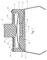
- FIG. 2shows a right angle mount sensor or switch package.
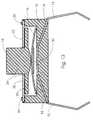
- FIG. 3shows a median cross section view of a prior art flat mount switch package.
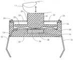
- FIG. 4shows a median cross section view of a flat mount sensor package in accordance with the present invention.
- FIG. 5shows a median cross section view of a flat mount sensor package in accordance with another embodiment of the present invention.
- FIG. 6shows a median cross section view of a flat mount sensor package in accordance with another embodiment of the present invention.
- FIG. 7shows a median cross section view of a flat mount sensor package in accordance with another embodiment of the present invention.
- FIG. 8shows a median cross section view of the embodiment of FIG. 7 in a depressed or actuated condition.
- FIG. 9shows a median cross section view of a flat mount sensor package in accordance with another embodiment of the present invention.
- FIG. 10shows a median cross section view of a flat mount sensor package in accordance with another embodiment of the present invention.
- FIG. 11shows a median cross section view of a flat mount sensor package in accordance with another embodiment of the present invention.
- FIG. 12shows a median cross section view of a flat mount sensor package in accordance with another embodiment of the present invention.
- FIG. 13shows a median cross section view of a flat mount sensor package in accordance with another embodiment of the present invention.
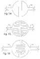
- FIGS. 14-16each show a top view of varied two conductive element arrangements.
- FIG. 1shows flat mount sensor package which appears as many prior art switches or sensors.
- the present inventioncan also appear as shown in FIG. 1 .
- FIG. 2shows a right angle mount sensor package which appears as many prior art switches or sensors.
- the present inventioncan also appear as shown in FIG. 2 .
- FIG. 3shows a median cross section view of a prior art flat mount sensor package showing structuring thereof and which is common to some of the present sensor embodiments, but lacking pressure-sensitive variable-conductance material 30 (see FIGS. 4 through 13) as used in the present invention.
- Shown in FIG. 3is a housing 10 typically of non-conductive plastics; two conductive elements 12 and 14 which are highly conductive and of fairly constant conductivity; the conductive elements 12 , 14 each fixed to housing 10 and in-part within housing 10 and in-part exposed external of housing 10 .
- Conductive elements 12 , 14are herein sometimes referred to as first conductive element 12 and second conductive element 14 , and are typically formed via stamping and bending of sheet metal.
- housing 10is of non-conductive plastics molded around portions of conductive elements 12 and 14 so as to retain the conductive elements in proper location to housing 10 .
- those portions or legs of conductive elements 12 , 14 external of housing 10serve as electrical conductors but also sometimes additionally serve as mechanical members for structural attachment to circuit boards, additionally they are sometimes connected such as by soldering directly to wires with housing 10 retained in a supportive socket of a host device.
- a conductive dome-cap 16typically made of metal, and positioned within a large recess or the interior open space defined by housing 10 and between a depressible actuator 18 and conductive elements 12 , 14 .
- dome-cap 16In some embodiments of the present sensor it is not necessary that dome-cap 16 be electrically conductive, and in other embodiments dome-cap 16 must be conductive as will become appreciated with continued reading.
- actuator 18is retained to housing 10 via a flange 20 of actuator 18 positioned beneath a housing plate 22 with a portion of actuator 18 extending through a hole 24 in housing plate 22 to be exposed external of housing 10 and thus accessible for depression by a finger, thumb or mechanical device.
- plastic studs 26formed of continuations of the material of housing 10 .
- Conductive elements 12 , 14are shown separated from one another within housing 10 and in a normally open state or circuit, being separated by space and the insulating material defining housing 10 .
- An end portion of first conductive element 12 within housing 10is shown positioned in constant contact with a side edge of dome-cap 16 .
- Dome-caps 16are typically circular disks having a domed or concavo-convexed shape. In the FIG.
- depression of actuator 18sufficiently causes dome-cap 16 to bow downward causing a center portion of dome-cap 16 to contact a more centrally positioned end of second conductive element 14 normally not in contact with dome-cap 16 .
- the contacting of the center portion of dome-cap 16 with second conductive element 14cause an electrical bridging or closing between first and second conductive elements 12 , 14 through conductive dome-cap 16 .
- Dome-cap 16 when pressed against sufficiently to bow toward second conductive element 14has resistance to moving, the resistance begins relatively low and increases toward a snap-through threshold wherein at the snap-through threshold dome-cap 16 “snaps-through” and moves further downward.
- a snap or clickcan be felt and in some applications heard (user discernable tactile feedback) as dome-cap 16 snaps-through its threshold.
- the snap-through dome-cap 16being of resilient design, returns to a raised position off of second conductive element 14 when actuator 18 is no longer depressed, and thus the switch or sensor is a momentary-On type.
- the snap-through dome-cap 16typically returns to a raised position off of second conductive element 14 and creates a user discernable tactile feedback while moving to the raised position.
- the resiliency of the dome-cap 16is used as the return spring for depressible actuator 18 , holding the actuator 18 raised or outward when not depressed by an external force.
- the portion of actuator 18 which is external of housing 10can be of numerous sizes and shapes, for example to accommodate the attachment of or contacting of extending and/or enclosing members such as buttons, triggers and the like, etc.
- the present inventionalso allows for various sizes and shapes of actuator 18 .
- FIG. 1shows four extensions external of housing 10 which those skilled in the art understand are in effect two conductive elements 12 , 14 wherein two of the extensions represent portions of first conductive element 12 external to housing 10 , and the other two extensions represent portions of second conductive element 14 ; as is common in many prior art switch packages for allowing increased strength and options in mechanical and electrical connecting, and such multi-extension external of housing 10 for each conductive element 12 , 14 can also be used with the present invention.
- a single thumb 11 or finger 11is shown depressing actuator 18 in FIG. 1 .
- FIG. 1shows four extensions external of housing 10 which those skilled in the art understand are in effect two conductive elements 12 , 14 wherein two of the extensions represent portions of first conductive element 12 external to housing 10 , and the other two extensions represent portions of second conductive element 14 ; as is common in many prior art switch packages for allowing increased strength and options in mechanical and electrical connecting, and such multi-extension external of housing 10 for each conductive element 12 , 14 can also be used with the present invention.
- electrical or electrically insulatingis relative to the applied voltage.
- FIG. 4shows a median cross section view of a flat mount sensor in accordance with the present invention and structured the same as the FIG. 3 sensor with the exception of the installation of a pressure-sensitive variable-conductance material 30 shown contacting and adhered in place on second conductive element 14 within housing 10 .
- Conductive dome-cap 16is shown in constant contact with first conductive element 12 , and operationally, pressure-sensitive variable-conductance material 30 is positioned as a variably conductive element electrically between the first and second conductive elements 12 , 14 such that depression of actuator 18 will depress dome-cap 16 pushing it through it's snap-through threshold resulting in a tactile feedback and dome-cap moving further presses onto pressure-sensitive variable-conductance material 30 to cause variable conductively dependant upon the degree of force thereagainst, and electricity will flow between first and second conductive elements 12 , 14 with both pressure-sensitive variable-conductance material 30 and dome-cap 16 in the current flow path.
- the pressure-sensitive variable-conductance material 30is a very important aspect, as is equally the tactile feedback from the snap-through dome-cap 16 of the present invention.
- the present inventioncan be viewed as an improved pressure-sensitive variable-conductance sensor improved by way of integrating a tactile feedback dome-cap therein, the invention can also be viewed as an improved momentary-On snap switch improved by way of integrating pressure-sensitive variable-conductance material electrically into a current flow path between the first and second conductive elements.
- sensors structured in accordance with the inventioncan be used in a wide variety of host devices in ways which can improve the usefulness, convenience and cost effectiveness of the host devices.
- variable conductancecan be achieved with materials having either variable resistive properties or variable rectifying properties.
- variable-conductancemeans either variably resistive or variably rectifying. Material having these qualities can be achieved utilizing various chemical compounds or formulas some of which I will herein detail for example. Additional information regarding such materials can be found in the Mitchell U.S. Pat. No 3,806,471 describing various feasible pressure-sensitive variable-conductance material formulas which can be utilized in the present invention. While it is generally anticipated that variable resistive type active materials are optimum for use in the pressure sensor(s) in the present invention, variable rectifying materials are also usable.
- An example formula or compound having variable rectifying propertiescan be made of any one of the active materials copper oxide, magnesium silicide, magnesium stannide, cuprous sulfide, (or the like) bound together with a rubbery or elastic type binder having resilient qualities such as silicone adhesive or the like.
- An example formula or compound having variable resistive propertiescan be made of the active material tungsten carbide powder (or other suitable material such as molybdenum disulfide, sponge iron, tin oxide, boron, and carbon powders, etc.) bound together with a rubbery or elastic type binder such as silicone rubber or the like having resilient qualities.
- tungsten carbide powderor other suitable material such as molybdenum disulfide, sponge iron, tin oxide, boron, and carbon powders, etc.
- a rubbery or elastic type bindersuch as silicone rubber or the like having resilient qualities.
- the active materialsmay be in proportion to the binder material typically in a rich ratio such as 80% active material to 20% binder by volume ranging to a ratio 98% to 2% binder, but can be varied widely from these ratios dependant on factors such as voltages to be applied, level or resistance range desired, depressive pressure anticipated, material thickness of applied pressure-sensitive variable-conductance material, surface contact area between the pressure-sensitive variable-conductance material and conductive elements 12 , 14 , whether an optional conductive plate 34 is to be used, binder type, manufacturing technique and specific active material used.
- a preferred method of manufacture for portions of that which is shown in FIGS. 7 and 11, i.e., material 30 with conductive cap 34is to create a sheet of pressure-sensitive variable-conductance material 30 adhered to a conductive sheet such as steel, aluminum or copper, for example, by applying a mixture of the still fluid variable-conductance material to the conductive sheet in a thin even layer before the binder material has cured. After the binder material has cured and adhered to the conductive sheet, a hole punch is used to create circular disks of the lamination of the conductive sheet and pressure-sensitive variable-conductance material. The disks may then be secured relative to any desired surface for contacting with circuit elements.
- Securing of the disksmay be accomplished with the use of adhesives, or with the silicone rubber as used in the formula to make pressure-sensitive variable-conductance material, or with any other suitable means.
- the adhesiveshould be spread thin or of a type such that significant electrical insulation is avoided.
- disks of the material 30can be formed by way of applying a thin layer of the still fluid variable-conductance material to a surface such as non-stick surface, and after the binder material has cured, removing the sheet of cured material 30 and using a hole punch or cutting-die such as a rotary die-cut process, create disks of the material 30 of a desired dimension.
- Another alternative to form the material 30 into a desired disk shapeis to inject or press the still fluid variable-conductance material 30 into a mold such as a cylindrical tube having an interior diameter commensurate with the exterior size and shaped of desire disk, allow the mixture to cure, and then open the mold to remove the material or press the material from the mold, and then slice the material 30 into the desired thickness.
- a moldsuch as a cylindrical tube having an interior diameter commensurate with the exterior size and shaped of desire disk, allow the mixture to cure, and then open the mold to remove the material or press the material from the mold, and then slice the material 30 into the desired thickness.
- Other methods of defining material 30 into suitable shapes and sizessuch as squirting from an applicator gun or otherwise applying the uncured material directly in place in the sensor, and then waiting for it to cure, can be used within the scope of the invention.
- pressure-sensitive variable-conductance material 30is positioned as a variably conductive element electrically between first conductive element 12 and second conductive element 14 , although in some embodiments snap-through dome-cap 16 must be electrically conductive for current flow to occur as will be appreciated with continued reading.
- Applied physical pressureis provided by a user depressing actuator 18 which applies pressure onto snap-through dome-cap 16 which moves onto pressure-sensitive variable-conductance material 30 which, dependant upon the force of the applied pressure, alters its conductivity (i.e., resistive or rectifying properties dependant upon the pressure sensor material utilized) and thereby provides analog electrical output proportional to the applied pressure, assuming a difference in electrical potential exists between conductive elements 12 and 14 .
- the analog electrical output of the variable-conductance material 30is output into or through or used in circuitry connected to the exposed portions of conductive elements 12 , 14 and capable of using such output in a manner which is representational of the pressure applied by the user.
- flat mount sensors and right angle mount sensors in accordance with the present inventionare electrically the same and generally only differ in the angular extension of the externally exposed conductive elements 12 and 14 relative to housing 10 and the exposed portion of actuator 18 .
- FIG. 5shows a median cross section view of a flat mount sensor package in accordance with another embodiment of the present invention similar to the FIG. 4 sensor and showing pressure-sensitive variable-conductance material 30 adhered to the underside of dome-cap 16 within housing 10 and held normally off but adjacent second conductive element 14 .
- snap-through dome-cap 16is electrically conductive and in constant contact with first conductive element 12 .
- Pressure-sensitive variable-conductance material 30is held off of or at least not held under significant pressure against the centrally positioned portion of second conductive element 14 by the normally raised position of snap-through dome-cap 16 .
- dome-cap 16which in this example carries pressure-sensitive variable-conductance material 30 then continues toward the central portion of second conductive element 14 and brings pressure-sensitive variable-conductance material 30 into compression against conductive element 14 .
- the tactile feedback and the contacting of pressure-sensitive variable-conductance material 30 against second conductive element 30may not occur at precisely the same instant, but preferably are sufficiently close as to be generally imperceptible to the human user, and this is generally true of all the present sensors herein described and shown in accordance with the present invention.
- compressive force against pressure-sensitive variable-conductance material 30causes it to become sufficiently conductive as to allow current flow therethrough, the degree of conductivity being dependant upon the applied, received or transferred pressure or force, which is controllable by the human user via varying depressive pressure on actuator 18 .
- dome-cap 16With variably resistive formula mixes of the pressure-sensitive variable-conductance material 30 as described above, the higher the compressive force thereon, the higher the electrical conductivity, i.e., the lower the resistivity thereof.
- dome-cap 16Upon sufficient release of depressive pressure on actuator 18 , dome-cap 16 returns under its own resilience to a normally raised position, the returning of dome-cap 16 raising pressure-sensitive variable-conductance material 30 from conductive element 14 or at least relieving compressive pressure thereon to such a degree as to open the circuit, and desirably also raising or pushing actuator 18 to a normal resting position.
- snap-through dome-cap 16When snap-through dome-cap 16 returns, it passes through it's snap-through threshold causing a tactile feedback or sensation detectable by the human user, thereby the human user is alerted to the fact that the sensor has been fully de-actuated or in effect has been rendered electrically open.
- FIG. 6shows a median cross section view of a flat mount sensor package in accordance with another embodiment of the present invention and showing pressure-sensitive variable-conductance material 30 contacting second conductive element 14 within a well 32 (small recess) within housing 10 .
- Well 32in this example improves containment of pressure-sensitive variable-conductance material 30 .
- Well 32offers advantage in containing the pressure-sensitive variable-conductance material 30 , but in a broad sense of the invention the sensor will function without well 32 .
- snap-through dome-capis electrically conductive and in constant contact with first conductive element 12 .
- dome-cap 16Pressure applied to actuator 18 onto dome-cap 16 moves dome-cap 16 through its snap-through threshold causing a tactile feedback to the human user to alert the human user of actuation of the sensor, i.e, the sensor rendered capable of some current flow between first and second conductive element 12 , 14 via passing through pressure-sensitive variable-conductance material 30 and the conductive dome-cap 16 .
- Dome-cap 16after snapping-through continues toward and basically instantaneously engages variable-conductance material 30 .
- Compressive force against pressure-sensitive variable-conductance material 30causes it to become sufficiently conductive as to allow current flow therethrough, the degree of conductivity dependant upon the applied pressure, which is controllable by the human user via varying depressive pressure on actuator 18 .
- dome-cap 16Upon sufficient release of depressive pressure on actuator 18 , dome-cap 16 returns under its own resilience to a normally raised position, the returning of dome-cap 16 relieving compressive pressure on pressure-sensitive variable-conductance material 30 to such a degree as to open the circuit, and desirably also raising or pushing actuator 18 to a normal resting position.
- dome-cap 16Upon sufficient release of depressive pressure on actuator 18 , dome-cap 16 returns under its own resilience to a normally raised position, the returning of dome-cap 16 relieving compressive pressure on pressure-sensitive variable-conductance material 30 to such a degree as to open the circuit, and desirably also raising or pushing actuator 18 to a normal resting position.
- snap-through dome-cap 16passes through it's snap-through threshold causing a tactile feedback or sensation detectable by the human user.
- FIG. 7shows a median cross section view of a flat mount sensor package in accordance with another embodiment of the present invention and showing pressure-sensitive variable-conductance material within a well 32 contacting second conductive element 14 and capped by a conductive cap 34 .
- the FIG. 7 embodimentis the same as the FIG. 6 embodiment with the exception of the added conductive plate 34 , which as described above can be defined as a lamination of pressure-sensitive variable-conductance material 30 onto conductive sheet material and then cut-out with a hole punch.
- Conductive plate 34 being atop pressure-sensitive variable-conductance material 30is effectively closing pressure-sensitive variable-conductance material 30 within well 32 .
- Conductive plate 34should either be flexible so as to be able to bow into pressure-sensitive variable-conductance material 30 , or loose fit in well 32 so as to be able to move in it's entirety into pressure-sensitive variable-conductance material 30 when pressure is applied thereto by snap-through dome-cap 16 .
- FIG. 8shows a median cross section view of the embodiment of FIG. 7 with actuator 18 depressed, such as it would be by a user's single finger 11 or thumb 11 , to such as degree as to cause dome-cap 16 to impinge upon conductive cap 34 atop the pressure-sensitive variable-conductance material 30 .
- the pressure applied to conductive cap 34is transferred in pressure-sensitive variable-conductance material 30 .
- dome-cap 16illustrates the common aspect of the actuator 18 depressing both dome-cap 16 and pressure-sensitive variable-conductance material 30 as would be common to all of the embodiments herein shown and described in accordance with the present invention, additionally, the arrangement of dome-cap 16 between actuator 18 and pressure-sensitive variable-conductance material 30 may be reversed, i.e., pressure-sensitive variable-conductance material 30 positioned atop dome-cap 16 with one of the conductive elements 12 or 14 moved atop pressure-sensitive variable-conductance material 30 , or actuator 18 may be an electrically conductive element of the embodiment.
- FIG. 9shows a median cross section view of a sensor in accordance with the present invention wherein pressure-sensitive variable-conductance material 30 is within a well 32 and sandwiched between first conductive element 12 , which has been extended from that shown in FIG. 8 to reach the center of the housing 10 , and second conductive element 14 .
- This sensor embodiment of the present inventiondemonstrates that snap-through dome-cap 16 need not always be electrically conductive. Dome-cap 16 may be conductive plastics or metal, but is not required to be in this embodiment, as first conductive element 12 has been extended to lay over and in spaced relationship to second conductive element 14 .
- Pressure-sensitive variable-conductance material 30is located between the two conductive elements 12 , 14 .
- dome-cap 16Pressure applied to actuator 18 onto dome-cap 16 moves dome-cap 16 through its snap-through threshold causing a tactile feedback to the human user. Dome-cap 16 then continues toward the central portion of first conductive element 12 , engages the element 12 , applies force thereto and the force is transferred into pressure-sensitive variable-conductance material 30 via a degree of flexibility in first conductive element 12 . Compressive force against pressure-sensitive variable-conductance material 30 causes it to become sufficiently conductive as to allow current flow therethrough, the degree of conductivity dependant upon the applied pressure or force, which is controllable by the human user via varying depressive pressure on actuator 18 .
- dome-cap 16Upon sufficient release of depressive pressure on actuator 18 , dome-cap 16 returns under its own resilience to a normally raised position, the returning of dome-cap 16 relieving pressure on conductive element 12 and pressure-sensitive variable-conductance material 30 to such a degree as to open the circuit, and desirably also raising or pushing actuator 18 to a normal resting position.
- snap-through dome-cap 16returns, it passes through it's snap-through threshold causing a tactile feedback or sensation detectable by the human user, thereby the human user is alerted to the fact that the sensor has been de-actuated or in effect has been rendered electrically open.
- FIG. 10shows a median cross section view of a sensor in accordance with another embodiment of the present invention wherein first and second conductive elements 12 , 14 are shown proximal to one another within a well 32 in housing 10 and about the same elevation as one another.
- Pressure-sensitive variable-conductance material 30is shown within well 32 and contacting each of conductive elements 12 , 14 and spanning therebetween beneath snap-through dome-cap 16 .
- Dome-cap 16 in this embodimentis not required to be electrically conductive. Pressure applied to actuator 18 onto dome-cap 16 moves dome-cap 16 through its snap-through threshold causing a tactile feedback. Dome-cap 16 then continues toward and basically instantaneously engages variable-conductance material 30 .
- Compressive force against pressure-sensitive variable-conductance material 30causes it to alter it's conductivity to become sufficiently conductive as to allow current flow therethrough and thus between conductive elements 12 and 14 , the degree of conductivity or alteration of conductivity dependant upon the applied pressure, which is controllable by the human user via varying depressive pressure on actuator 18 .
- dome-cap 16Upon sufficient release of depressive pressure on actuator 18 , dome-cap 16 returns under its own resilience to a normally raised position, the returning of dome-cap 16 relieving compressive pressure on pressure-sensitive variable-conductance material 30 to such a degree as to open the circuit, and desirably also raising or pushing actuator 18 to a normal resting position.
- snap-through dome-cap 16returns, it passes through it's snap-through threshold causing a tactile feedback or sensation detectable by the human user.
- FIG. 11shows a median cross section view of a sensor in accordance with another embodiment of the present invention wherein first and second conductive elements 12 , 14 are shown proximal to one another within a well 32 in housing 10 , and pressure-sensitive variable-conductance material 30 contacting each of the conductive elements 12 , 14 and spanning therebetween, with the addition of a conductive cap 34 atop pressure-sensitive variable-conductance material 30 beneath snap-through dome-cap 16 .
- FIG. 12shows a median cross section view of a sensor in accordance with another embodiment of the present invention which is basically the same as the FIG. 10 embodiment only sans well 32 .
- FIG. 13shows a median cross section view of a sensor in accordance with another embodiment of the present invention which is basically the same as the FIG. 11 embodiment only with the pressure-sensitive variable-conductance material 30 adhered to the underside of snap-through dome-cap 16 .
- FIGS. 14-16show a top view of two conductive elements 12 , 14 in various proximal arrangements as they may be applied in the embodiments of FIGS. 10-13 within housing 10 .
- FIG. 14shows two conductive elements 12 , 14 as two side-by-side plate-like pads.
- FIG. 15shows two conductive elements 12 , 14 as two side-by-side pads having opposed fingers.
- FIG. 16shows two conductive elements 12 , 14 as two side-by-side pads defined by interdigitated fingers.
- the novel manufacturing step of installing pressure-sensitive variable-conductance material 30includes the proper locating of material 30 positioned for serving as a flow path for electricity to flow between the two conductive elements 12 , 14 , wherein in some embodiments tactile feedback dome-cap 16 is electrically conductive and in other embodiments the dome-cap 16 is not required to be conductive.
- Such installation and positioningmust be such that depressible actuator 18 and pressure-sensitive variable-conductance material 30 are in positional relationship to allow transference of externally applied force onto depressible actuator 18 through dome-cap 16 and onto pressure-sensitive variable-conductance material 30 .
Landscapes
- Chemical & Material Sciences (AREA)
- Dispersion Chemistry (AREA)
- Engineering & Computer Science (AREA)
- Microelectronics & Electronic Packaging (AREA)
- Push-Button Switches (AREA)
Abstract
Description
Claims (24)
Priority Applications (2)
| Application Number | Priority Date | Filing Date | Title |
|---|---|---|---|
| US09/955,838US6563415B2 (en) | 1996-07-05 | 2001-09-18 | Analog sensor(s) with snap-through tactile feedback |
| US10/437,395US20030201869A1 (en) | 1996-07-05 | 2003-05-12 | Analog sensor(s) with tactile feedback |
Applications Claiming Priority (4)
| Application Number | Priority Date | Filing Date | Title |
|---|---|---|---|
| US08/677,378US6222525B1 (en) | 1992-03-05 | 1996-07-05 | Image controllers with sheet connected sensors |
| US09/106,825US5999084A (en) | 1998-06-29 | 1998-06-29 | Variable-conductance sensor |
| US09/455,821US6351205B1 (en) | 1996-07-05 | 1999-12-06 | Variable-conductance sensor |
| US09/955,838US6563415B2 (en) | 1996-07-05 | 2001-09-18 | Analog sensor(s) with snap-through tactile feedback |
Related Parent Applications (2)
| Application Number | Title | Priority Date | Filing Date |
|---|---|---|---|
| US09/455,821DivisionUS6351205B1 (en) | 1996-07-05 | 1999-12-06 | Variable-conductance sensor |
| US09455521Division | 1999-12-07 |
Related Child Applications (1)
| Application Number | Title | Priority Date | Filing Date |
|---|---|---|---|
| US10/437,395ContinuationUS20030201869A1 (en) | 1996-07-05 | 2003-05-12 | Analog sensor(s) with tactile feedback |
Publications (2)
| Publication Number | Publication Date |
|---|---|
| US20020067241A1 US20020067241A1 (en) | 2002-06-06 |
| US6563415B2true US6563415B2 (en) | 2003-05-13 |
Family
ID=26804065
Family Applications (3)
| Application Number | Title | Priority Date | Filing Date |
|---|---|---|---|
| US09/455,821Expired - Fee RelatedUS6351205B1 (en) | 1996-07-05 | 1999-12-06 | Variable-conductance sensor |
| US09/955,838Expired - Fee RelatedUS6563415B2 (en) | 1996-07-05 | 2001-09-18 | Analog sensor(s) with snap-through tactile feedback |
| US10/437,395AbandonedUS20030201869A1 (en) | 1996-07-05 | 2003-05-12 | Analog sensor(s) with tactile feedback |
Family Applications Before (1)
| Application Number | Title | Priority Date | Filing Date |
|---|---|---|---|
| US09/455,821Expired - Fee RelatedUS6351205B1 (en) | 1996-07-05 | 1999-12-06 | Variable-conductance sensor |
Family Applications After (1)
| Application Number | Title | Priority Date | Filing Date |
|---|---|---|---|
| US10/437,395AbandonedUS20030201869A1 (en) | 1996-07-05 | 2003-05-12 | Analog sensor(s) with tactile feedback |
Country Status (1)
| Country | Link |
|---|---|
| US (3) | US6351205B1 (en) |
Cited By (25)
| Publication number | Priority date | Publication date | Assignee | Title |
|---|---|---|---|---|
| US6661332B1 (en)* | 2003-03-10 | 2003-12-09 | Wei Hsu | Press-type varistor switch |
| US20030234291A1 (en)* | 2002-06-03 | 2003-12-25 | Thomas Wulff | Re-configurable trigger assembly |
| US20050057515A1 (en)* | 2003-09-16 | 2005-03-17 | Microsoft Corporation | Computer keyboard with quantitatively force-sensing keys |
| US20050057514A1 (en)* | 2003-09-16 | 2005-03-17 | Microsoft Corporation | Quantitatively force-sensing computer keyboard |
| US6906700B1 (en) | 1992-03-05 | 2005-06-14 | Anascape | 3D controller with vibration |
| US20060028437A1 (en)* | 1992-03-05 | 2006-02-09 | Armstrong Brad A | Image controller |
| US20060028435A1 (en)* | 1995-02-23 | 2006-02-09 | Armstrong Brad A | Image controller |
| US20060066570A1 (en)* | 2004-09-27 | 2006-03-30 | Trifilo Timothy M | Pointing device and method |
| US20060261983A1 (en)* | 2005-05-16 | 2006-11-23 | Research In Motion Limited | Key system for a communication device |
| US20070271048A1 (en)* | 2006-02-10 | 2007-11-22 | David Feist | Systems using variable resistance zones and stops for generating inputs to an electronic device |
| US20080110737A1 (en)* | 2006-11-14 | 2008-05-15 | Chun-Hsien Chen | Trigger Device Used In A Palmtop Computer |
| US20080266254A1 (en)* | 2007-04-24 | 2008-10-30 | Irobot Corporation | Control System for a Remote Vehicle |
| US20080275667A1 (en)* | 2006-03-28 | 2008-11-06 | Nintendo Co., Ltd. | Inclination calculation apparatus and inclination calculation program, and game apparatus and game program |
| USD629320S1 (en)* | 2009-09-25 | 2010-12-21 | Hokuriku Electric Industry Co., Ltd. | Force sensor |
| US8396611B2 (en) | 2006-07-14 | 2013-03-12 | Irobot Corporation | Autonomous behaviors for a remote vehicle |
| US8587422B2 (en) | 2010-03-31 | 2013-11-19 | Tk Holdings, Inc. | Occupant sensing system |
| US8725230B2 (en) | 2010-04-02 | 2014-05-13 | Tk Holdings Inc. | Steering wheel with hand sensors |
| US9007190B2 (en) | 2010-03-31 | 2015-04-14 | Tk Holdings Inc. | Steering wheel sensors |
| US9696223B2 (en) | 2012-09-17 | 2017-07-04 | Tk Holdings Inc. | Single layer force sensor |
| US9727031B2 (en) | 2012-04-13 | 2017-08-08 | Tk Holdings Inc. | Pressure sensor including a pressure sensitive material for use with control systems and methods of using the same |
| US10274627B2 (en) | 2015-10-30 | 2019-04-30 | Ion Geophysical Corporation | Ocean bottom seismic systems |
| US11114259B2 (en) | 2017-02-15 | 2021-09-07 | Panasonic Intellectual Property Management Co., Ltd. | Switch body |
| US11204365B2 (en) | 2018-09-13 | 2021-12-21 | Ion Geophysical Corporation | Multi-axis, single mass accelerometer |
| USD997911S1 (en)* | 2018-03-01 | 2023-09-05 | Festool Gmbh | Remote control |
| US20240167896A1 (en)* | 2021-03-01 | 2024-05-23 | Hahn-Schickard-Gesellschaft Für Angewandte Forschung E. V. | Device for measuring deformations, stresses, forces and/or torques in a plurality of axes |
Families Citing this family (63)
| Publication number | Priority date | Publication date | Assignee | Title |
|---|---|---|---|---|
| US6343991B1 (en)* | 1997-10-01 | 2002-02-05 | Brad A. Armstrong | Game control with analog pressure sensor |
| US6351205B1 (en)* | 1996-07-05 | 2002-02-26 | Brad A. Armstrong | Variable-conductance sensor |
| US20040160414A1 (en)* | 1996-07-05 | 2004-08-19 | Armstrong Brad A. | Image controller |
| TW581701B (en)* | 2000-01-14 | 2004-04-01 | Sony Computer Entertainment Inc | Recording medium, method of using a computer and computer for executing role-playing games |
| EP1320024B1 (en)* | 2000-08-23 | 2007-01-24 | Nintendo Co., Limited | Information processor, information storage medium, program, and operating device for game machine |
| DE20021422U1 (en)* | 2000-12-19 | 2001-06-13 | Bechmann, Peter, 82487 Oberammergau | Test device for checking the pressure load on the foot that occurs when walking |
| US6909354B2 (en)* | 2001-02-08 | 2005-06-21 | Interlink Electronics, Inc. | Electronic pressure sensitive transducer apparatus and method for manufacturing same |
| JP2004037350A (en)* | 2002-07-05 | 2004-02-05 | Nitta Ind Corp | Resistance type sensor |
| US7050045B2 (en)* | 2003-01-07 | 2006-05-23 | Interlink Electronics, Inc. | Miniature highly manufacturable mouse pointing device |
| US20060146018A1 (en)* | 2005-01-04 | 2006-07-06 | Arneson Theodore R | Joystick with tactile feedback |
| US7573464B2 (en)* | 2006-07-20 | 2009-08-11 | Interlink Electronics, Inc. | Shape adaptable resistive touchpad |
| GB0621247D0 (en)* | 2006-10-25 | 2006-12-06 | Univ Surrey | Separation process |
| EP2001034A3 (en)* | 2007-06-04 | 2009-12-30 | Panasonic Corporation | Movable Contact Element and Switch Using the Same |
| US7825345B1 (en)* | 2008-08-26 | 2010-11-02 | Kano Yoshio W | Reversely mounted tactile switch assembly and printed circuit board therewith |
| US8487759B2 (en) | 2009-09-30 | 2013-07-16 | Apple Inc. | Self adapting haptic device |
| US20110267294A1 (en)* | 2010-04-29 | 2011-11-03 | Nokia Corporation | Apparatus and method for providing tactile feedback for user |
| US10013058B2 (en) | 2010-09-21 | 2018-07-03 | Apple Inc. | Touch-based user interface with haptic feedback |
| US10120446B2 (en) | 2010-11-19 | 2018-11-06 | Apple Inc. | Haptic input device |
| US20130164068A1 (en) | 2011-12-21 | 2013-06-27 | Apple Inc. | Bonded keyboard and method for making the same |
| US9493342B2 (en) | 2012-06-21 | 2016-11-15 | Nextinput, Inc. | Wafer level MEMS force dies |
| EP2870445A1 (en) | 2012-07-05 | 2015-05-13 | Ian Campbell | Microelectromechanical load sensor and methods of manufacturing the same |
| US9178509B2 (en) | 2012-09-28 | 2015-11-03 | Apple Inc. | Ultra low travel keyboard |
| WO2015020663A1 (en) | 2013-08-08 | 2015-02-12 | Honessa Development Laboratories Llc | Sculpted waveforms with no or reduced unforced response |
| US9779592B1 (en) | 2013-09-26 | 2017-10-03 | Apple Inc. | Geared haptic feedback element |
| US9928950B2 (en) | 2013-09-27 | 2018-03-27 | Apple Inc. | Polarized magnetic actuators for haptic response |
| HK1222728A1 (en) | 2013-09-27 | 2017-07-07 | 苹果公司 | Band with haptic actuators |
| US10126817B2 (en) | 2013-09-29 | 2018-11-13 | Apple Inc. | Devices and methods for creating haptic effects |
| CN105683865B (en) | 2013-09-30 | 2018-11-09 | 苹果公司 | Magnetic actuator for haptic response |
| US9317118B2 (en) | 2013-10-22 | 2016-04-19 | Apple Inc. | Touch surface for simulating materials |
| CN105814510B (en) | 2013-12-10 | 2019-06-07 | 苹果公司 | Band body attachment mechanism with haptic response |
| EP3094950B1 (en) | 2014-01-13 | 2022-12-21 | Nextinput, Inc. | Miniaturized and ruggedized wafer level mems force sensors |
| US9501912B1 (en) | 2014-01-27 | 2016-11-22 | Apple Inc. | Haptic feedback device with a rotating mass of variable eccentricity |
| CN106489116B (en) | 2014-04-21 | 2019-08-16 | 苹果公司 | Distribution of forces for multi-touch input devices for electronic devices |
| DE102015209639A1 (en) | 2014-06-03 | 2015-12-03 | Apple Inc. | Linear actuator |
| WO2016036671A2 (en) | 2014-09-02 | 2016-03-10 | Apple Inc. | Haptic notifications |
| US10353467B2 (en) | 2015-03-06 | 2019-07-16 | Apple Inc. | Calibration of haptic devices |
| AU2016100399B4 (en) | 2015-04-17 | 2017-02-02 | Apple Inc. | Contracting and elongating materials for providing input and output for an electronic device |
| CN107848788B (en) | 2015-06-10 | 2023-11-24 | 触控解决方案股份有限公司 | Ruggedized wafer-level MEMS force sensor with tolerance trench |
| US10068727B2 (en) | 2015-08-04 | 2018-09-04 | Apple Inc. | Key surface lighting |
| WO2017044618A1 (en) | 2015-09-08 | 2017-03-16 | Apple Inc. | Linear actuators for use in electronic devices |
| KR102423148B1 (en)* | 2015-11-26 | 2022-07-21 | 삼성전자주식회사 | Methode for obtaining user input and electronic device thereof |
| US10039080B2 (en) | 2016-03-04 | 2018-07-31 | Apple Inc. | Situationally-aware alerts |
| US10268272B2 (en) | 2016-03-31 | 2019-04-23 | Apple Inc. | Dampening mechanical modes of a haptic actuator using a delay |
| USD878311S1 (en)* | 2016-11-07 | 2020-03-17 | Citizen Electronics Co., Ltd. | Switch spring |
| EP3580539A4 (en) | 2017-02-09 | 2020-11-25 | Nextinput, Inc. | INTEGRATED DIGITAL FORCE SENSORS AND RELATED METHOD OF MANUFACTURING |
| US11243125B2 (en) | 2017-02-09 | 2022-02-08 | Nextinput, Inc. | Integrated piezoresistive and piezoelectric fusion force sensor |
| US10622538B2 (en) | 2017-07-18 | 2020-04-14 | Apple Inc. | Techniques for providing a haptic output and sensing a haptic input using a piezoelectric body |
| US11221263B2 (en) | 2017-07-19 | 2022-01-11 | Nextinput, Inc. | Microelectromechanical force sensor having a strain transfer layer arranged on the sensor die |
| WO2019023309A1 (en) | 2017-07-25 | 2019-01-31 | Nextinput, Inc. | Integrated fingerprint and force sensor |
| WO2019023552A1 (en) | 2017-07-27 | 2019-01-31 | Nextinput, Inc. | A wafer bonded piezoresistive and piezoelectric force sensor and related methods of manufacture |
| WO2019079420A1 (en) | 2017-10-17 | 2019-04-25 | Nextinput, Inc. | Temperature coefficient of offset compensation for force sensor and strain gauge |
| WO2019090057A1 (en) | 2017-11-02 | 2019-05-09 | Nextinput, Inc. | Sealed force sensor with etch stop layer |
| WO2019099821A1 (en) | 2017-11-16 | 2019-05-23 | Nextinput, Inc. | Force attenuator for force sensor |
| US10691211B2 (en) | 2018-09-28 | 2020-06-23 | Apple Inc. | Button providing force sensing and/or haptic output |
| US10599223B1 (en) | 2018-09-28 | 2020-03-24 | Apple Inc. | Button providing force sensing and/or haptic output |
| US10962427B2 (en) | 2019-01-10 | 2021-03-30 | Nextinput, Inc. | Slotted MEMS force sensor |
| DE102019204178B4 (en)* | 2019-03-26 | 2022-08-04 | Zf Friedrichshafen Ag | Method for producing a sensor device and component and/or chassis component with such a sensor device |
| US10523233B1 (en)* | 2019-04-26 | 2019-12-31 | Cattron Holdings, Inc. | Membrane digital analog switches |
| US11380470B2 (en) | 2019-09-24 | 2022-07-05 | Apple Inc. | Methods to control force in reluctance actuators based on flux related parameters |
| CN211507472U (en) | 2020-04-24 | 2020-09-15 | 湃瑞电子科技(苏州)有限公司 | Pressure sensor and button structure and button module thereof |
| EP4256597A1 (en)* | 2020-12-04 | 2023-10-11 | Clean Energy Labs, LLC | Electrically conductive membrane pressure switch |
| US11977683B2 (en) | 2021-03-12 | 2024-05-07 | Apple Inc. | Modular systems configured to provide localized haptic feedback using inertial actuators |
| US11809631B2 (en) | 2021-09-21 | 2023-11-07 | Apple Inc. | Reluctance haptic engine for an electronic device |
Citations (99)
| Publication number | Priority date | Publication date | Assignee | Title |
|---|---|---|---|---|
| US3611068A (en) | 1970-05-20 | 1971-10-05 | Matsushita Electric Industrial Co Ltd | Contactless pressure sensitive semiconductor switch |
| US3771037A (en) | 1973-03-15 | 1973-11-06 | Nasa | Solid state controller three-axes controller |
| US3806471A (en) | 1968-04-29 | 1974-04-23 | R Mitchell | Pressure responsive resistive material |
| US3952173A (en) | 1973-11-09 | 1976-04-20 | Kabushiki Kaisha Tokai Rika Denki Seisakusho | Switching apparatus |
| US3988556A (en) | 1973-06-21 | 1976-10-26 | Kabushiki Kaisha Tokai Rika Denki Seisakusho | Switching apparatus |
| US4224602A (en) | 1978-12-04 | 1980-09-23 | Gte Sylvania Incorporated | Signalling device |
| GB2058462A (en) | 1979-09-10 | 1981-04-08 | Shinetsu Polymer Co | Push button switch |
| US4268815A (en) | 1979-11-26 | 1981-05-19 | Eventoff Franklin Neal | Multi-function touch switch apparatus |
| US4276538A (en) | 1980-01-07 | 1981-06-30 | Franklin N. Eventoff | Touch switch keyboard apparatus |
| US4301337A (en) | 1980-03-31 | 1981-11-17 | Eventoff Franklin Neal | Dual lateral switch device |
| US4313113A (en) | 1980-03-24 | 1982-01-26 | Xerox Corporation | Cursor control |
| US4314228A (en) | 1980-04-16 | 1982-02-02 | Eventoff Franklin Neal | Pressure transducer |
| US4315238A (en) | 1979-09-24 | 1982-02-09 | Eventoff Franklin Neal | Bounceless switch apparatus |
| DE3031484A1 (en) | 1980-08-21 | 1982-11-04 | Grundig Emv | Snap action push button switch for printed circuit - applies pressure to resilient film with conductive coating in region of contacts |
| GB2113920A (en) | 1982-01-26 | 1983-08-10 | Alps Electric Co Ltd | Push-button electrical switch |
| JPS60175401A (en) | 1984-02-22 | 1985-09-09 | 旭化成株式会社 | Pressure sensitive conductive element |
| US4552360A (en) | 1982-09-29 | 1985-11-12 | Coleco Industries, Inc. | Video game with control of movement and rate of movement of a plurality of game objects |
| US4615252A (en) | 1984-02-01 | 1986-10-07 | Nippon Gakki Seizo Kabushiki Kaisha | Touch control apparatus for electronic keyboard instrument |
| US4673919A (en) | 1983-08-10 | 1987-06-16 | Mitsubishi Denki Kabushiki Kaisha | Manual control device |
| DE3543890A1 (en) | 1985-12-12 | 1987-06-19 | Thomson Brandt Gmbh | Input element |
| JPS62160623A (en) | 1986-01-10 | 1987-07-16 | 株式会社山武 | Display panel with touch switch |
| US4694231A (en) | 1986-04-18 | 1987-09-15 | Mecanotron Corporation | Robotic skin |
| US4733214A (en) | 1983-05-23 | 1988-03-22 | Andresen Herman J | Multi-directional controller having resiliently biased cam and cam follower for tactile feedback |
| DE3634912A1 (en) | 1986-10-14 | 1988-04-28 | Link Kg J | Trigger stick |
| US4786895A (en) | 1985-08-02 | 1988-11-22 | Xeltron, S. A. | Control panel |
| US4866542A (en) | 1985-12-27 | 1989-09-12 | Sony Corporation | Remote-controlling commander with multi-function rotary dial |
| EP0337458A2 (en) | 1988-04-13 | 1989-10-18 | Namco, Ltd. | Apparatus for synthesizing analog signals in PCM |
| JPH02158105A (en) | 1988-12-12 | 1990-06-18 | Yokohama Rubber Co Ltd:The | Laminated type pressure sensitive material |
| US4975676A (en) | 1989-11-13 | 1990-12-04 | Spectra Symbol Corp. | Glass membrane touch-controlled circuit apparatus for voltage selection |
| DE4019211A1 (en) | 1989-06-28 | 1991-01-03 | Lutron Electronics Co | POWER CONTROLLER WITH TOUCH SWITCH |
| GB2233499A (en) | 1989-06-28 | 1991-01-09 | Mitsubishi Electric Corp | Switch |
| JPH03108701A (en) | 1989-09-22 | 1991-05-08 | Canon Inc | Sheet variable resistor |
| EP0470615A1 (en) | 1990-08-09 | 1992-02-12 | Nintendo Co., Ltd. | Controller for a game machine |
| US5103404A (en) | 1985-12-06 | 1992-04-07 | Tensor Development, Inc. | Feedback for a manipulator |
| JPH04155707A (en) | 1990-10-19 | 1992-05-28 | Yokohama Rubber Co Ltd:The | Pressure sensitive electric conductive body |
| US5132658A (en) | 1990-04-19 | 1992-07-21 | Sensym, Inc. | Micromachined silicon potentiometer responsive to pressure |
| US5164697A (en) | 1990-04-11 | 1992-11-17 | Nokia Unterhaltangselektronik Gmbh | Input keyboard for an electronic appliance in entertainment electronics |
| US5189355A (en) | 1992-04-10 | 1993-02-23 | Ampex Corporation | Interactive rotary controller system with tactile feedback |
| US5196782A (en) | 1989-06-28 | 1993-03-23 | Lutron Electronics Co., Inc. | Touch-operated power control |
| JPH0587760A (en) | 1991-03-18 | 1993-04-06 | Toto Ltd | Gas sensor and production thereof |
| US5200597A (en) | 1991-02-07 | 1993-04-06 | Psc, Inc. | Digitally controlled system for scanning and reading bar codes |
| JPH05151828A (en) | 1991-11-29 | 1993-06-18 | Yokohama Rubber Co Ltd:The | Pressure-sensitive conductive material |
| GB2267392A (en) | 1992-05-28 | 1993-12-01 | Philip Collins | Pressure-sensitive variable resistor with slidably moving member |
| USD342740S (en) | 1992-04-24 | 1993-12-28 | Gerald Parker | Wrist supported remote control |
| EP0579448A1 (en) | 1992-07-14 | 1994-01-19 | Texas Instruments Incorporated | Seal apparatus and method for forming |
| US5287089A (en) | 1992-05-13 | 1994-02-15 | Micro-Integration Corporation | Hand manipulatable computer input device |
| RU2010369C1 (en) | 1987-12-16 | 1994-03-30 | Смыслов Игорь Иванович | Variable resistor |
| US5311779A (en) | 1992-01-03 | 1994-05-17 | Inabagomu Co., Ltd. | Pressure-sensitive sensor |
| US5315204A (en) | 1990-04-16 | 1994-05-24 | The Whitaker Corporation | Piezoelectric snap action switch |
| JPH06154422A (en) | 1992-11-24 | 1994-06-03 | Namco Ltd | Game device operation buttons |
| US5364108A (en) | 1992-04-10 | 1994-11-15 | Esnouf Philip S | Game apparatus |
| US5365494A (en) | 1994-02-07 | 1994-11-15 | Mike Lynch | Radio alarm clock with reminder capability |
| US5376913A (en) | 1993-07-12 | 1994-12-27 | Motorola, Inc. | Variable resistor utilizing an elastomeric actuator |
| US5396235A (en) | 1990-09-05 | 1995-03-07 | Canon Kabushiki Kaisha | Numeral setting apparatus |
| US5440237A (en) | 1993-06-01 | 1995-08-08 | Incontrol Solutions, Inc. | Electronic force sensing with sensor normalization |
| US5457478A (en) | 1992-10-26 | 1995-10-10 | Firstperson, Inc. | Control device |
| JPH07281824A (en) | 1994-04-11 | 1995-10-27 | Namco Ltd | Analog input device |
| JPH07302159A (en) | 1994-04-28 | 1995-11-14 | Sega Enterp Ltd | Switch device |
| US5550339A (en) | 1994-10-31 | 1996-08-27 | Cts Corporation | Variable speed tactile switch |
| US5565891A (en) | 1992-03-05 | 1996-10-15 | Armstrong; Brad A. | Six degrees of freedom graphics controller |
| US5640566A (en) | 1994-08-01 | 1997-06-17 | Apple Computer, Inc. | Method of forming an editor |
| GB2308448A (en) | 1995-12-19 | 1997-06-25 | Samsung Display Devices Co Ltd | Touch panel |
| JPH09213168A (en) | 1996-02-02 | 1997-08-15 | Teikoku Tsushin Kogyo Co Ltd | Pressure sensitive element |
| JPH09218737A (en) | 1996-02-13 | 1997-08-19 | Namco Ltd | Control amount input method and apparatus thereof |
| JPH09223607A (en) | 1996-02-14 | 1997-08-26 | Teikoku Tsushin Kogyo Co Ltd | Pressure-sensitive electronic components |
| DE19606408A1 (en) | 1996-02-21 | 1997-08-28 | Contelec Ag | Variable resistive element with polymer-film force-sensing resistor |
| US5670955A (en) | 1995-01-31 | 1997-09-23 | Microsoft Corporation | Method and apparatus for generating directional and force vector in an input device |
| US5673237A (en) | 1996-01-29 | 1997-09-30 | Blank; Steve | Steering wheel alarm clock |
| US5675329A (en) | 1996-05-09 | 1997-10-07 | International Business Machines Corporation | Method of obtaining a second function from keys on a keyboard using pressure differentiation |
| US5689285A (en) | 1993-09-13 | 1997-11-18 | Asher; David J. | Joystick with membrane sensor |
| US5764219A (en) | 1992-09-25 | 1998-06-09 | Ibm Corporation | Controller for improved computer pointing devices |
| US5778404A (en) | 1995-08-07 | 1998-07-07 | Apple Computer, Inc. | String inserter for pen-based computer systems and method for providing same |
| US5790102A (en) | 1996-03-28 | 1998-08-04 | Nassimi; Shary | Pressure sensitive computer mouse |
| US5847639A (en) | 1994-02-17 | 1998-12-08 | Yaniger; Stuart I. | Layered pressure transducer land method for making same |
| US5847305A (en) | 1993-12-21 | 1998-12-08 | Casio Computer Co., Ltd. | Remote control devices for electronic devices |
| US5854624A (en) | 1996-09-12 | 1998-12-29 | Innovative Device Technologies, Inc. | Pocket-sized user interface for internet browser terminals and the like |
| US5867808A (en) | 1994-01-14 | 1999-02-02 | International Business Machines Corporation | Force transducer with screen printed strain gauges |
| US5883619A (en) | 1996-11-12 | 1999-03-16 | Primax Electronics Ltd. | Computer mouse for scrolling a view of an image |
| US5889236A (en) | 1992-06-08 | 1999-03-30 | Synaptics Incorporated | Pressure sensitive scrollbar feature |
| US5895471A (en) | 1997-07-11 | 1999-04-20 | Unwired Planet, Inc. | Providing a directory of frequently used hyperlinks on a remote server |
| US5898359A (en) | 1997-12-19 | 1999-04-27 | Delco Electronics Corp. | Diffusion-barrier materials for thick-film piezoresistors and sensors formed therewith |
| US5910798A (en) | 1996-11-27 | 1999-06-08 | Lg Electronics Inc. | Apparatus for moving a cursor on a screen |
| US5943044A (en) | 1996-08-05 | 1999-08-24 | Interlink Electronics | Force sensing semiconductive touchpad |
| US5948066A (en) | 1997-03-13 | 1999-09-07 | Motorola, Inc. | System and method for delivery of information over narrow-band communications links |
| US5974238A (en) | 1996-08-07 | 1999-10-26 | Compaq Computer Corporation | Automatic data synchronization between a handheld and a host computer using pseudo cache including tags and logical data elements |
| US5995026A (en) | 1997-10-21 | 1999-11-30 | Compaq Computer Corporation | Programmable multiple output force-sensing keyboard |
| US5999084A (en) | 1998-06-29 | 1999-12-07 | Armstrong; Brad A. | Variable-conductance sensor |
| US6020884A (en) | 1996-11-08 | 2000-02-01 | America Online, Inc. | System integrating an on-line service community with a foreign service |
| US6049812A (en) | 1996-11-18 | 2000-04-11 | International Business Machines Corp. | Browser and plural active URL manager for network computers |
| US6102802A (en) | 1997-10-01 | 2000-08-15 | Armstrong; Brad A. | Game controller with analog pressure sensor(s) |
| US6118979A (en) | 1996-11-22 | 2000-09-12 | Robert B. Nicholson, III | Method for signaling an incoming telephone call without an audible signal |
| US6135886A (en) | 1997-10-01 | 2000-10-24 | Armstrong; Brad A. | Variable-conductance sensor with elastomeric dome-cap |
| US6157935A (en) | 1996-12-17 | 2000-12-05 | Tran; Bao Q. | Remote data access and management system |
| US6185158B1 (en) | 1996-08-30 | 2001-02-06 | Citizen Watch Co., Ltd. | Small electronic apparatus having function display |
| US6198473B1 (en) | 1998-10-06 | 2001-03-06 | Brad A. Armstrong | Computer mouse with enhance control button (s) |
| EP1080753A1 (en) | 1999-01-29 | 2001-03-07 | Namco Ltd. | Game machine |
| US6208271B1 (en) | 1998-09-04 | 2001-03-27 | Brad A. Armstrong | Remote controller with analog button(s) |
| US6222525B1 (en) | 1992-03-05 | 2001-04-24 | Brad A. Armstrong | Image controllers with sheet connected sensors |
| US6351205B1 (en)* | 1996-07-05 | 2002-02-26 | Brad A. Armstrong | Variable-conductance sensor |
Family Cites Families (55)
| Publication number | Priority date | Publication date | Assignee | Title |
|---|---|---|---|---|
| US3693425A (en)* | 1970-04-30 | 1972-09-26 | Joseph M Starita | Force measuring apparatus |
| US3710050A (en) | 1970-09-14 | 1973-01-09 | A Richards | Electronic pressure sensitive switch |
| US4099409A (en)* | 1977-07-05 | 1978-07-11 | The Bendix Corporation | Multi-axis load cell with arcuate flexures |
| US4158759A (en)* | 1977-09-16 | 1979-06-19 | Teccor Electronics, Inc. | Microwave oven control system |
| US4216467A (en)* | 1977-12-22 | 1980-08-05 | Westinghouse Electric Corp. | Hand controller |
| US4246452A (en)* | 1979-01-05 | 1981-01-20 | Mattel, Inc. | Switch apparatus |
| FR2451807A1 (en)* | 1979-03-22 | 1980-10-17 | Renault | SIX AXIS MANIPULATOR |
| US4297542A (en)* | 1979-12-19 | 1981-10-27 | Shumway Anthony G | Folded circuit switch apparatus having multiple contacts |
| IT1129409B (en)* | 1980-03-07 | 1986-06-04 | Fiat Ricerche | SIX DEGREE TRANSDUCER OF FREEDOM TO CONVERT INTO ELECTRIC SIGNALS THE FORCES AND MOMENTS APPLIED TO A MOBILE BODY PARTICULARLY TO THE MOBILE ARM OF A ROBOT |
| DE3170063D1 (en)* | 1980-12-27 | 1985-05-23 | Toshiba Kk | Coffee maker |
| US4369971A (en) | 1981-01-07 | 1983-01-25 | Mattel, Inc. | Electronic bowling game |
| US4469330A (en)* | 1982-01-07 | 1984-09-04 | Atari, Inc. | Controller unit for video game |
| US4536746A (en)* | 1982-09-30 | 1985-08-20 | The Mercado Venture | Transducer for converting three dimensional mechanical input displacements into a corresponding electrical output signal |
| JPS60184690A (en) | 1984-03-02 | 1985-09-20 | Permelec Electrode Ltd | Durable electrode and its manufacture |
| US4684089A (en)* | 1984-10-22 | 1987-08-04 | Lely Cornelis V D | Computer with universal input member for use on stationary and mobile platforms |
| JPS61140009A (en)* | 1984-12-12 | 1986-06-27 | 信越ポリマ−株式会社 | Push button switch |
| US4935728A (en)* | 1985-01-02 | 1990-06-19 | Altra Corporation | Computer control |
| US4670743A (en)* | 1985-01-31 | 1987-06-02 | General Instrument Corporation | Keyboard cursor controller |
| US4604509A (en)* | 1985-02-01 | 1986-08-05 | Honeywell Inc. | Elastomeric push button return element for providing enhanced tactile feedback |
| US4811608A (en)* | 1985-12-18 | 1989-03-14 | Spatial Systems Pty Limited | Force and torque converter |
| US4910503A (en)* | 1987-06-15 | 1990-03-20 | Brodsky Stephen L | Multi-function input device and system |
| DE3722046C1 (en)* | 1987-07-03 | 1988-11-10 | Magenwirth Gmbh Co Gustav | Joystick for generating electrical control signals |
| US4924216A (en)* | 1988-02-12 | 1990-05-08 | Acemore International Ltd. | Joystick controller apparatus |
| US4858930A (en)* | 1988-06-07 | 1989-08-22 | Namco, Ltd. | Game system |
| US4933670A (en)* | 1988-07-21 | 1990-06-12 | Picker International, Inc. | Multi-axis trackball |
| US5184830A (en)* | 1989-01-10 | 1993-02-09 | Nintendo Company Limited | Compact hand-held video game system |
| US5231386A (en)* | 1990-07-24 | 1993-07-27 | Home Row, Inc. | Keyswitch-integrated pointing assembly |
| US6040821A (en)* | 1989-09-26 | 2000-03-21 | Incontrol Solutions, Inc. | Cursor tracking |
| US5128671A (en)* | 1990-04-12 | 1992-07-07 | Ltv Aerospace And Defense Company | Control device having multiple degrees of freedom |
| US5541622A (en)* | 1990-07-24 | 1996-07-30 | Incontrol Solutions, Inc. | Miniature isometric joystick |
| JPH04176235A (en)* | 1990-11-08 | 1992-06-23 | Nintendo Co Ltd | Communication adaptor for game machine |
| JPH04218824A (en)* | 1990-12-19 | 1992-08-10 | Yaskawa Electric Corp | Multidimensional information input device |
| US5142931A (en)* | 1991-02-14 | 1992-09-01 | Honeywell Inc. | 3 degree of freedom hand controller |
| US5278557A (en)* | 1991-02-19 | 1994-01-11 | Key Tronic Corporation | Cursor movement control key and electronic computer keyboard for computers having a video display |
| US5203563A (en)* | 1991-03-21 | 1993-04-20 | Atari Games Corporation | Shaker control device |
| US5139439A (en)* | 1991-07-16 | 1992-08-18 | Veridata Electronics Inc. | Portable computer with detachable cartridge type interface device |
| US5237311A (en)* | 1991-08-01 | 1993-08-17 | Picker International, Inc. | Hingedly supported integrated trackball and selection device |
| US5298919A (en)* | 1991-08-02 | 1994-03-29 | Multipoint Technology Corporation | Multi-dimensional input device |
| US5293158A (en)* | 1992-05-05 | 1994-03-08 | Alps Electric Co., Ltd. | X-Y direction input device |
| GB2278729A (en)* | 1993-06-04 | 1994-12-07 | Txc Corp | Direction control key assembly |
| JP3366413B2 (en)* | 1993-07-27 | 2003-01-14 | 任天堂株式会社 | Display information conversion apparatus and information processing system |
| USD355901S (en)* | 1993-08-06 | 1995-02-28 | Logitech, Inc. | Computer mouse |
| US5555004A (en)* | 1993-08-30 | 1996-09-10 | Hosiden Corporation | Input control device |
| US5537212A (en) | 1993-10-12 | 1996-07-16 | Lazer-Tron Corporation | Method and apparatus for sensing the color of an object |
| US5606594A (en)* | 1994-01-27 | 1997-02-25 | Dell Usa, L.P. | Communication accessory and method of telecommunicating for a PDA |
| US5391083A (en)* | 1994-02-25 | 1995-02-21 | R. A. Tool & Die, Inc. | Computer card connector |
| MY118477A (en)* | 1994-04-20 | 2004-11-30 | Sony Corp | Communication terminal apparatus and control method thereof |
| US5510812A (en) | 1994-04-22 | 1996-04-23 | Hasbro, Inc. | Piezoresistive input device |
| US5669818A (en)* | 1995-03-23 | 1997-09-23 | Thorner; Craig | Seat-based tactile sensation generator |
| US6422941B1 (en)* | 1994-09-21 | 2002-07-23 | Craig Thorner | Universal tactile feedback system for computer video games and simulations |
| US5670988A (en)* | 1995-09-05 | 1997-09-23 | Interlink Electronics, Inc. | Trigger operated electronic device |
| KR100629818B1 (en)* | 1996-10-11 | 2007-07-13 | 소니 컴퓨터 엔터테인먼트 인코포레이티드 | Operating Device for Game Machines |
| US5923317A (en)* | 1997-06-17 | 1999-07-13 | Thrustmaster, Inc. | Two-handed controller for video games and simulations |
| US6067863A (en) | 1997-08-29 | 2000-05-30 | Eaton Corporation | Multiple-function selector utilizing a force sensitive, variable impedance device |
| US6256011B1 (en)* | 1997-12-03 | 2001-07-03 | Immersion Corporation | Multi-function control device with force feedback |
- 1999
- 1999-12-06USUS09/455,821patent/US6351205B1/ennot_activeExpired - Fee Related
- 2001
- 2001-09-18USUS09/955,838patent/US6563415B2/ennot_activeExpired - Fee Related
- 2003
- 2003-05-12USUS10/437,395patent/US20030201869A1/ennot_activeAbandoned
Patent Citations (101)
| Publication number | Priority date | Publication date | Assignee | Title |
|---|---|---|---|---|
| US3806471A (en) | 1968-04-29 | 1974-04-23 | R Mitchell | Pressure responsive resistive material |
| US3611068A (en) | 1970-05-20 | 1971-10-05 | Matsushita Electric Industrial Co Ltd | Contactless pressure sensitive semiconductor switch |
| US3771037A (en) | 1973-03-15 | 1973-11-06 | Nasa | Solid state controller three-axes controller |
| US3988556A (en) | 1973-06-21 | 1976-10-26 | Kabushiki Kaisha Tokai Rika Denki Seisakusho | Switching apparatus |
| US3952173A (en) | 1973-11-09 | 1976-04-20 | Kabushiki Kaisha Tokai Rika Denki Seisakusho | Switching apparatus |
| US4224602A (en) | 1978-12-04 | 1980-09-23 | Gte Sylvania Incorporated | Signalling device |
| GB2058462A (en) | 1979-09-10 | 1981-04-08 | Shinetsu Polymer Co | Push button switch |
| US4315238A (en) | 1979-09-24 | 1982-02-09 | Eventoff Franklin Neal | Bounceless switch apparatus |
| US4268815A (en) | 1979-11-26 | 1981-05-19 | Eventoff Franklin Neal | Multi-function touch switch apparatus |
| US4276538A (en) | 1980-01-07 | 1981-06-30 | Franklin N. Eventoff | Touch switch keyboard apparatus |
| US4313113A (en) | 1980-03-24 | 1982-01-26 | Xerox Corporation | Cursor control |
| US4301337A (en) | 1980-03-31 | 1981-11-17 | Eventoff Franklin Neal | Dual lateral switch device |
| US4314228A (en) | 1980-04-16 | 1982-02-02 | Eventoff Franklin Neal | Pressure transducer |
| DE3031484A1 (en) | 1980-08-21 | 1982-11-04 | Grundig Emv | Snap action push button switch for printed circuit - applies pressure to resilient film with conductive coating in region of contacts |
| GB2113920A (en) | 1982-01-26 | 1983-08-10 | Alps Electric Co Ltd | Push-button electrical switch |
| US4552360A (en) | 1982-09-29 | 1985-11-12 | Coleco Industries, Inc. | Video game with control of movement and rate of movement of a plurality of game objects |
| US4733214A (en) | 1983-05-23 | 1988-03-22 | Andresen Herman J | Multi-directional controller having resiliently biased cam and cam follower for tactile feedback |
| US4673919A (en) | 1983-08-10 | 1987-06-16 | Mitsubishi Denki Kabushiki Kaisha | Manual control device |
| US4615252A (en) | 1984-02-01 | 1986-10-07 | Nippon Gakki Seizo Kabushiki Kaisha | Touch control apparatus for electronic keyboard instrument |
| JPS60175401A (en) | 1984-02-22 | 1985-09-09 | 旭化成株式会社 | Pressure sensitive conductive element |
| US4786895A (en) | 1985-08-02 | 1988-11-22 | Xeltron, S. A. | Control panel |
| US5103404A (en) | 1985-12-06 | 1992-04-07 | Tensor Development, Inc. | Feedback for a manipulator |
| DE3543890A1 (en) | 1985-12-12 | 1987-06-19 | Thomson Brandt Gmbh | Input element |
| US4866542A (en) | 1985-12-27 | 1989-09-12 | Sony Corporation | Remote-controlling commander with multi-function rotary dial |
| JPS62160623A (en) | 1986-01-10 | 1987-07-16 | 株式会社山武 | Display panel with touch switch |
| US4694231A (en) | 1986-04-18 | 1987-09-15 | Mecanotron Corporation | Robotic skin |
| DE3634912A1 (en) | 1986-10-14 | 1988-04-28 | Link Kg J | Trigger stick |
| RU2010369C1 (en) | 1987-12-16 | 1994-03-30 | Смыслов Игорь Иванович | Variable resistor |
| EP0337458A2 (en) | 1988-04-13 | 1989-10-18 | Namco, Ltd. | Apparatus for synthesizing analog signals in PCM |
| JPH02158105A (en) | 1988-12-12 | 1990-06-18 | Yokohama Rubber Co Ltd:The | Laminated type pressure sensitive material |
| GB2233499A (en) | 1989-06-28 | 1991-01-09 | Mitsubishi Electric Corp | Switch |
| DE4019211A1 (en) | 1989-06-28 | 1991-01-03 | Lutron Electronics Co | POWER CONTROLLER WITH TOUCH SWITCH |
| US5196782A (en) | 1989-06-28 | 1993-03-23 | Lutron Electronics Co., Inc. | Touch-operated power control |
| JPH03108701A (en) | 1989-09-22 | 1991-05-08 | Canon Inc | Sheet variable resistor |
| US4975676A (en) | 1989-11-13 | 1990-12-04 | Spectra Symbol Corp. | Glass membrane touch-controlled circuit apparatus for voltage selection |
| US5164697A (en) | 1990-04-11 | 1992-11-17 | Nokia Unterhaltangselektronik Gmbh | Input keyboard for an electronic appliance in entertainment electronics |
| US5315204A (en) | 1990-04-16 | 1994-05-24 | The Whitaker Corporation | Piezoelectric snap action switch |
| US5132658A (en) | 1990-04-19 | 1992-07-21 | Sensym, Inc. | Micromachined silicon potentiometer responsive to pressure |
| US5207426A (en) | 1990-08-09 | 1993-05-04 | Nintendo Co. Ltd. | Controller for a game machine |
| EP0470615A1 (en) | 1990-08-09 | 1992-02-12 | Nintendo Co., Ltd. | Controller for a game machine |
| US5396235A (en) | 1990-09-05 | 1995-03-07 | Canon Kabushiki Kaisha | Numeral setting apparatus |
| JPH04155707A (en) | 1990-10-19 | 1992-05-28 | Yokohama Rubber Co Ltd:The | Pressure sensitive electric conductive body |
| US5200597A (en) | 1991-02-07 | 1993-04-06 | Psc, Inc. | Digitally controlled system for scanning and reading bar codes |
| JPH0587760A (en) | 1991-03-18 | 1993-04-06 | Toto Ltd | Gas sensor and production thereof |
| JPH05151828A (en) | 1991-11-29 | 1993-06-18 | Yokohama Rubber Co Ltd:The | Pressure-sensitive conductive material |
| US5311779A (en) | 1992-01-03 | 1994-05-17 | Inabagomu Co., Ltd. | Pressure-sensitive sensor |
| US6222525B1 (en) | 1992-03-05 | 2001-04-24 | Brad A. Armstrong | Image controllers with sheet connected sensors |
| US5589828A (en) | 1992-03-05 | 1996-12-31 | Armstrong; Brad A. | 6 Degrees of freedom controller with capability of tactile feedback |
| US5565891A (en) | 1992-03-05 | 1996-10-15 | Armstrong; Brad A. | Six degrees of freedom graphics controller |
| US5364108A (en) | 1992-04-10 | 1994-11-15 | Esnouf Philip S | Game apparatus |
| US5189355A (en) | 1992-04-10 | 1993-02-23 | Ampex Corporation | Interactive rotary controller system with tactile feedback |
| USD342740S (en) | 1992-04-24 | 1993-12-28 | Gerald Parker | Wrist supported remote control |
| US5287089A (en) | 1992-05-13 | 1994-02-15 | Micro-Integration Corporation | Hand manipulatable computer input device |
| GB2267392A (en) | 1992-05-28 | 1993-12-01 | Philip Collins | Pressure-sensitive variable resistor with slidably moving member |
| US5889236A (en) | 1992-06-08 | 1999-03-30 | Synaptics Incorporated | Pressure sensitive scrollbar feature |
| EP0579448A1 (en) | 1992-07-14 | 1994-01-19 | Texas Instruments Incorporated | Seal apparatus and method for forming |
| US5764219A (en) | 1992-09-25 | 1998-06-09 | Ibm Corporation | Controller for improved computer pointing devices |
| US5457478A (en) | 1992-10-26 | 1995-10-10 | Firstperson, Inc. | Control device |
| JPH06154422A (en) | 1992-11-24 | 1994-06-03 | Namco Ltd | Game device operation buttons |
| US5440237A (en) | 1993-06-01 | 1995-08-08 | Incontrol Solutions, Inc. | Electronic force sensing with sensor normalization |
| US5376913A (en) | 1993-07-12 | 1994-12-27 | Motorola, Inc. | Variable resistor utilizing an elastomeric actuator |
| US5689285A (en) | 1993-09-13 | 1997-11-18 | Asher; David J. | Joystick with membrane sensor |
| US5847305A (en) | 1993-12-21 | 1998-12-08 | Casio Computer Co., Ltd. | Remote control devices for electronic devices |
| US5867808A (en) | 1994-01-14 | 1999-02-02 | International Business Machines Corporation | Force transducer with screen printed strain gauges |
| US5365494A (en) | 1994-02-07 | 1994-11-15 | Mike Lynch | Radio alarm clock with reminder capability |
| US5847639A (en) | 1994-02-17 | 1998-12-08 | Yaniger; Stuart I. | Layered pressure transducer land method for making same |
| JPH07281824A (en) | 1994-04-11 | 1995-10-27 | Namco Ltd | Analog input device |
| JPH07302159A (en) | 1994-04-28 | 1995-11-14 | Sega Enterp Ltd | Switch device |
| US5640566A (en) | 1994-08-01 | 1997-06-17 | Apple Computer, Inc. | Method of forming an editor |
| US5550339A (en) | 1994-10-31 | 1996-08-27 | Cts Corporation | Variable speed tactile switch |
| US5670955A (en) | 1995-01-31 | 1997-09-23 | Microsoft Corporation | Method and apparatus for generating directional and force vector in an input device |
| US5778404A (en) | 1995-08-07 | 1998-07-07 | Apple Computer, Inc. | String inserter for pen-based computer systems and method for providing same |
| GB2308448A (en) | 1995-12-19 | 1997-06-25 | Samsung Display Devices Co Ltd | Touch panel |
| US5673237A (en) | 1996-01-29 | 1997-09-30 | Blank; Steve | Steering wheel alarm clock |
| JPH09213168A (en) | 1996-02-02 | 1997-08-15 | Teikoku Tsushin Kogyo Co Ltd | Pressure sensitive element |
| JPH09218737A (en) | 1996-02-13 | 1997-08-19 | Namco Ltd | Control amount input method and apparatus thereof |
| JPH09223607A (en) | 1996-02-14 | 1997-08-26 | Teikoku Tsushin Kogyo Co Ltd | Pressure-sensitive electronic components |
| DE19606408A1 (en) | 1996-02-21 | 1997-08-28 | Contelec Ag | Variable resistive element with polymer-film force-sensing resistor |
| US5790102A (en) | 1996-03-28 | 1998-08-04 | Nassimi; Shary | Pressure sensitive computer mouse |
| US5675329A (en) | 1996-05-09 | 1997-10-07 | International Business Machines Corporation | Method of obtaining a second function from keys on a keyboard using pressure differentiation |
| US6351205B1 (en)* | 1996-07-05 | 2002-02-26 | Brad A. Armstrong | Variable-conductance sensor |
| US5943044A (en) | 1996-08-05 | 1999-08-24 | Interlink Electronics | Force sensing semiconductive touchpad |
| US5974238A (en) | 1996-08-07 | 1999-10-26 | Compaq Computer Corporation | Automatic data synchronization between a handheld and a host computer using pseudo cache including tags and logical data elements |
| US6185158B1 (en) | 1996-08-30 | 2001-02-06 | Citizen Watch Co., Ltd. | Small electronic apparatus having function display |
| US5854624A (en) | 1996-09-12 | 1998-12-29 | Innovative Device Technologies, Inc. | Pocket-sized user interface for internet browser terminals and the like |
| US6020884A (en) | 1996-11-08 | 2000-02-01 | America Online, Inc. | System integrating an on-line service community with a foreign service |
| US5883619A (en) | 1996-11-12 | 1999-03-16 | Primax Electronics Ltd. | Computer mouse for scrolling a view of an image |
| US6049812A (en) | 1996-11-18 | 2000-04-11 | International Business Machines Corp. | Browser and plural active URL manager for network computers |
| US6118979A (en) | 1996-11-22 | 2000-09-12 | Robert B. Nicholson, III | Method for signaling an incoming telephone call without an audible signal |
| US5910798A (en) | 1996-11-27 | 1999-06-08 | Lg Electronics Inc. | Apparatus for moving a cursor on a screen |
| US6157935A (en) | 1996-12-17 | 2000-12-05 | Tran; Bao Q. | Remote data access and management system |
| US5948066A (en) | 1997-03-13 | 1999-09-07 | Motorola, Inc. | System and method for delivery of information over narrow-band communications links |
| US5895471A (en) | 1997-07-11 | 1999-04-20 | Unwired Planet, Inc. | Providing a directory of frequently used hyperlinks on a remote server |
| US6135886A (en) | 1997-10-01 | 2000-10-24 | Armstrong; Brad A. | Variable-conductance sensor with elastomeric dome-cap |
| US6102802A (en) | 1997-10-01 | 2000-08-15 | Armstrong; Brad A. | Game controller with analog pressure sensor(s) |
| US5995026A (en) | 1997-10-21 | 1999-11-30 | Compaq Computer Corporation | Programmable multiple output force-sensing keyboard |
| US5898359A (en) | 1997-12-19 | 1999-04-27 | Delco Electronics Corp. | Diffusion-barrier materials for thick-film piezoresistors and sensors formed therewith |
| US5999084A (en) | 1998-06-29 | 1999-12-07 | Armstrong; Brad A. | Variable-conductance sensor |
| US6208271B1 (en) | 1998-09-04 | 2001-03-27 | Brad A. Armstrong | Remote controller with analog button(s) |
| US6198473B1 (en) | 1998-10-06 | 2001-03-06 | Brad A. Armstrong | Computer mouse with enhance control button (s) |
| EP1080753A1 (en) | 1999-01-29 | 2001-03-07 | Namco Ltd. | Game machine |
Non-Patent Citations (3)
| Title |
|---|
| IBM Technical Disclosure Bulletin pp230-235 Feb. 1990 Mouse Ball-Actuating Device With Forge And Tactile Feedback full article sent. |
| Research Disclosure Nov. 1987 28373 Joystick with Tactile Feedback full article sent. |
| S.F. Kambic, IBM Technical Disclosure Bulletin, full article sent vol. 20 No. 5 Oct. 1977. |
Cited By (57)
| Publication number | Priority date | Publication date | Assignee | Title |
|---|---|---|---|---|
| US20060028437A1 (en)* | 1992-03-05 | 2006-02-09 | Armstrong Brad A | Image controller |
| US7345670B2 (en) | 1992-03-05 | 2008-03-18 | Anascape | Image controller |
| US20060028436A1 (en)* | 1992-03-05 | 2006-02-09 | Armstrong Brad A | Image controller |
| US9081426B2 (en) | 1992-03-05 | 2015-07-14 | Anascape, Ltd. | Image controller |
| US6906700B1 (en) | 1992-03-05 | 2005-06-14 | Anascape | 3D controller with vibration |
| US20060028435A1 (en)* | 1995-02-23 | 2006-02-09 | Armstrong Brad A | Image controller |
| US8674932B2 (en) | 1996-07-05 | 2014-03-18 | Anascape, Ltd. | Image controller |
| US7481372B2 (en) | 2002-06-03 | 2009-01-27 | Symbol Technologies, Inc. | Re-configurable trigger assembly |
| US20030234291A1 (en)* | 2002-06-03 | 2003-12-25 | Thomas Wulff | Re-configurable trigger assembly |
| US7055749B2 (en)* | 2002-06-03 | 2006-06-06 | Symbol Technologies, Inc. | Re-configurable trigger assembly |
| US20060186207A1 (en)* | 2002-06-03 | 2006-08-24 | Symbol Technologies, Inc. | Re-configurable trigger assembly |
| US7306156B2 (en) | 2002-06-03 | 2007-12-11 | Symbol Technologies, Inc. | Re-configurable trigger assembly |
| US20080164318A1 (en)* | 2002-06-03 | 2008-07-10 | Symbol Technologies, Inc. | Re-configurable trigger assembly |
| US6661332B1 (en)* | 2003-03-10 | 2003-12-09 | Wei Hsu | Press-type varistor switch |
| US7256768B2 (en) | 2003-09-16 | 2007-08-14 | Microsoft Corporation | Computer keyboard with quantitatively force-sensing keys |
| US7123241B2 (en)* | 2003-09-16 | 2006-10-17 | Microsoft Corporation | Quantitatively force-sensing computer keyboard |
| US20050057514A1 (en)* | 2003-09-16 | 2005-03-17 | Microsoft Corporation | Quantitatively force-sensing computer keyboard |
| US20050057515A1 (en)* | 2003-09-16 | 2005-03-17 | Microsoft Corporation | Computer keyboard with quantitatively force-sensing keys |
| US20060066570A1 (en)* | 2004-09-27 | 2006-03-30 | Trifilo Timothy M | Pointing device and method |
| US20060261983A1 (en)* | 2005-05-16 | 2006-11-23 | Research In Motion Limited | Key system for a communication device |
| US20080211696A1 (en)* | 2005-05-16 | 2008-09-04 | Research In Motion Limited | Key system for an electronic device |
| US8963744B2 (en) | 2005-05-16 | 2015-02-24 | Blackberry Limited | Key system for an electronic device |
| US7385530B2 (en)* | 2005-05-16 | 2008-06-10 | Research In Motion Limited | Key system for a communication device |
| US20070271048A1 (en)* | 2006-02-10 | 2007-11-22 | David Feist | Systems using variable resistance zones and stops for generating inputs to an electronic device |
| US7684953B2 (en)* | 2006-02-10 | 2010-03-23 | Authentec, Inc. | Systems using variable resistance zones and stops for generating inputs to an electronic device |
| US7877224B2 (en) | 2006-03-28 | 2011-01-25 | Nintendo Co, Ltd. | Inclination calculation apparatus and inclination calculation program, and game apparatus and game program |
| US20100309117A1 (en)* | 2006-03-28 | 2010-12-09 | Nintendo Co., Ltd | Inclination calculation apparatus and inclination calculation program, and game apparatus and game program |
| US20080275667A1 (en)* | 2006-03-28 | 2008-11-06 | Nintendo Co., Ltd. | Inclination calculation apparatus and inclination calculation program, and game apparatus and game program |
| US7596466B2 (en) | 2006-03-28 | 2009-09-29 | Nintendo Co., Ltd. | Inclination calculation apparatus and inclination calculation program, and game apparatus and game program |
| US8473245B2 (en) | 2006-03-28 | 2013-06-25 | Nintendo Co., Ltd. | Inclination calculation apparatus and inclination calculation program, and game apparatus and game program |
| US20110238368A1 (en)* | 2006-03-28 | 2011-09-29 | Nintendo Co., Ltd. | Inclination calculation apparatus and inclination calculation program, and game apparatus and game program |
| US8041536B2 (en) | 2006-03-28 | 2011-10-18 | Nintendo Co., Ltd. | Inclination calculation apparatus and inclination calculation program, and game apparatus and game program |
| US9791860B2 (en) | 2006-05-12 | 2017-10-17 | Irobot Defense Holdings Inc. | Autonomous behaviors for a remote vehicle |
| US8396611B2 (en) | 2006-07-14 | 2013-03-12 | Irobot Corporation | Autonomous behaviors for a remote vehicle |
| US8134430B2 (en)* | 2006-11-14 | 2012-03-13 | Unitech Electronics Co., Ltd. | Trigger device used in a palmtop computer |
| US20080110737A1 (en)* | 2006-11-14 | 2008-05-15 | Chun-Hsien Chen | Trigger Device Used In A Palmtop Computer |
| US8199109B2 (en) | 2007-04-24 | 2012-06-12 | Irobot Corporation | Control system for a remote vehicle |
| US8350810B2 (en) | 2007-04-24 | 2013-01-08 | Irobot Corporation | Control system for a remote vehicle |
| US20110109549A1 (en)* | 2007-04-24 | 2011-05-12 | Irobot Corporation | Control System for a Remote Vehicle |
| US7843431B2 (en) | 2007-04-24 | 2010-11-30 | Irobot Corporation | Control system for a remote vehicle |
| US8760397B2 (en) | 2007-04-24 | 2014-06-24 | Irobot Corporation | Control system for a remote vehicle |
| US20080266254A1 (en)* | 2007-04-24 | 2008-10-30 | Irobot Corporation | Control System for a Remote Vehicle |
| US9195256B2 (en) | 2007-04-24 | 2015-11-24 | Irobot Corporation | Control system for a remote vehicle |
| USD629320S1 (en)* | 2009-09-25 | 2010-12-21 | Hokuriku Electric Industry Co., Ltd. | Force sensor |
| US8587422B2 (en) | 2010-03-31 | 2013-11-19 | Tk Holdings, Inc. | Occupant sensing system |
| US9007190B2 (en) | 2010-03-31 | 2015-04-14 | Tk Holdings Inc. | Steering wheel sensors |
| US8725230B2 (en) | 2010-04-02 | 2014-05-13 | Tk Holdings Inc. | Steering wheel with hand sensors |
| US9727031B2 (en) | 2012-04-13 | 2017-08-08 | Tk Holdings Inc. | Pressure sensor including a pressure sensitive material for use with control systems and methods of using the same |
| US9696223B2 (en) | 2012-09-17 | 2017-07-04 | Tk Holdings Inc. | Single layer force sensor |
| US10274627B2 (en) | 2015-10-30 | 2019-04-30 | Ion Geophysical Corporation | Ocean bottom seismic systems |
| US10545254B2 (en) | 2015-10-30 | 2020-01-28 | Ion Geophysical Corporation | Multi-Axis, single mass accelerometer |
| US11561314B2 (en) | 2015-10-30 | 2023-01-24 | TGS-NOPEC Geophysical Corporation | Multi-axis, single mass accelerometer |
| US12019197B2 (en) | 2015-10-30 | 2024-06-25 | Tgs-Nopec Geophysical Company | Multi-axis, single mass accelerometer |
| US11114259B2 (en) | 2017-02-15 | 2021-09-07 | Panasonic Intellectual Property Management Co., Ltd. | Switch body |
| USD997911S1 (en)* | 2018-03-01 | 2023-09-05 | Festool Gmbh | Remote control |
| US11204365B2 (en) | 2018-09-13 | 2021-12-21 | Ion Geophysical Corporation | Multi-axis, single mass accelerometer |
| US20240167896A1 (en)* | 2021-03-01 | 2024-05-23 | Hahn-Schickard-Gesellschaft Für Angewandte Forschung E. V. | Device for measuring deformations, stresses, forces and/or torques in a plurality of axes |
Also Published As
| Publication number | Publication date |
|---|---|
| US20020067241A1 (en) | 2002-06-06 |
| US20030201869A1 (en) | 2003-10-30 |
| US6351205B1 (en) | 2002-02-26 |
Similar Documents
| Publication | Publication Date | Title |
|---|---|---|
| US6563415B2 (en) | Analog sensor(s) with snap-through tactile feedback | |
| US5999084A (en) | Variable-conductance sensor | |
| US6198473B1 (en) | Computer mouse with enhance control button (s) | |
| US6344791B1 (en) | Variable sensor with tactile feedback | |
| US6102802A (en) | Game controller with analog pressure sensor(s) | |
| US6343991B1 (en) | Game control with analog pressure sensor | |
| US20020084986A1 (en) | Computer mouse with specialized button(s) | |
| US6135886A (en) | Variable-conductance sensor with elastomeric dome-cap | |
| US5912612A (en) | Multi-speed multi-direction analog pointing device | |
| US6069552A (en) | Directionally sensitive switch | |
| US6208271B1 (en) | Remote controller with analog button(s) | |
| US5278557A (en) | Cursor movement control key and electronic computer keyboard for computers having a video display | |
| US20030083131A1 (en) | Controller with analog pressure sensor (s) | |
| US5287089A (en) | Hand manipulatable computer input device | |
| US6369692B1 (en) | Directionally sensitive switch | |
| JPH04230918A (en) | Imput key board for arc-over electron device | |
| JPH0256903A (en) | Variable resistance device | |
| JP2000353604A (en) | Variable resistor | |
| WO2002029837A1 (en) | Multi-directional input device and electronic device using the input device | |
| US20030227406A1 (en) | Remote controller with analog button(s) | |
| EP2101338B1 (en) | Pressure sensitive conductive sheet and panel switch using the same | |
| WO1981000787A1 (en) | Switch structure with touch element | |
| EP1236213A1 (en) | Remote controller with pressure sensitive buttons | |
| US20030179180A1 (en) | Coordinates inputting apparatus | |
| JP3954776B2 (en) | Input device |
Legal Events
| Date | Code | Title | Description |
|---|---|---|---|
| CC | Certificate of correction | ||
| AS | Assignment | Owner name:ANASCAPE, LTD., TEXAS Free format text:ASSIGNMENT OF ASSIGNORS INTEREST;ASSIGNORS:GLOBAL DEVICES, A GENERAL PARTNERSHIP;ARMSTRONG, BRAD;BOWMAN, STEVEN;REEL/FRAME:018239/0569 Effective date:20060724 Owner name:ANASCAPE, LTD., TEXAS Free format text:ASSIGNMENT OF ASSIGNORS INTEREST;ASSIGNOR:BOWMAN, STEVEN;REEL/FRAME:018239/0573 Effective date:20060724 Owner name:ANASCAPE, LTD., TEXAS Free format text:ASSIGNMENT OF ASSIGNORS INTEREST;ASSIGNOR:ARMSTRONG, BRAD;REEL/FRAME:018239/0713 Effective date:20060726 Owner name:ANASCAPE, LTD., TEXAS Free format text:ASSIGNMENT OF ASSIGNORS INTEREST;ASSIGNOR:GP TRUST, BY BRAND ARMSTONG, TRUSTEE;REEL/FRAME:018268/0812 Effective date:20060726 Owner name:ANASCAPE, LTD., TEXAS Free format text:ASSIGNMENT OF ASSIGNORS INTEREST;ASSIGNOR:TYLER, KELLY;REEL/FRAME:018279/0733 Effective date:20060724 Owner name:ANASCAPE, LTD., TEXAS Free format text:ASSIGNMENT OF ASSIGNORS INTEREST;ASSIGNOR:6-DOF TRUST, BY BRAD ARMSTRONG, TRUSTEE;REEL/FRAME:018268/0865 Effective date:20060726 | |
| REMI | Maintenance fee reminder mailed | ||
| FEPP | Fee payment procedure | Free format text:PAT HOLDER NO LONGER CLAIMS SMALL ENTITY STATUS, ENTITY STATUS SET TO UNDISCOUNTED (ORIGINAL EVENT CODE: STOL); ENTITY STATUS OF PATENT OWNER: LARGE ENTITY | |
| REFU | Refund | Free format text:REFUND - SURCHARGE FOR LATE PAYMENT, SMALL ENTITY (ORIGINAL EVENT CODE: R2554); ENTITY STATUS OF PATENT OWNER: LARGE ENTITY Free format text:REFUND - SURCHARGE, PETITION TO ACCEPT PYMT AFTER EXP, UNINTENTIONAL (ORIGINAL EVENT CODE: R2551); ENTITY STATUS OF PATENT OWNER: LARGE ENTITY | |
| RR | Request for reexamination filed | Effective date:20070131 | |
| FPAY | Fee payment | Year of fee payment:4 | |
| SULP | Surcharge for late payment | ||
| RR | Request for reexamination filed | Effective date:20070419 | |
| REMI | Maintenance fee reminder mailed | ||
| FPAY | Fee payment | Year of fee payment:8 | |
| SULP | Surcharge for late payment | Year of fee payment:7 | |
| FPB1 | Reexamination decision cancelled all claims | ||
| REMI | Maintenance fee reminder mailed | ||
| LAPS | Lapse for failure to pay maintenance fees | ||
| STCH | Information on status: patent discontinuation | Free format text:PATENT EXPIRED DUE TO NONPAYMENT OF MAINTENANCE FEES UNDER 37 CFR 1.362 | |
| FP | Lapsed due to failure to pay maintenance fee | Effective date:20150513 |