US6562299B1 - Method and apparatus for preparing cytological specimens - Google Patents
Method and apparatus for preparing cytological specimensDownload PDFInfo
- Publication number
- US6562299B1 US6562299B1US09/521,531US52153100AUS6562299B1US 6562299 B1US6562299 B1US 6562299B1US 52153100 AUS52153100 AUS 52153100AUS 6562299 B1US6562299 B1US 6562299B1
- Authority
- US
- United States
- Prior art keywords
- sample
- specimen
- slide
- vial
- samples
- Prior art date
- Legal status (The legal status is an assumption and is not a legal conclusion. Google has not performed a legal analysis and makes no representation as to the accuracy of the status listed.)
- Expired - Lifetime
Links
Images


Classifications
- B—PERFORMING OPERATIONS; TRANSPORTING
- B01—PHYSICAL OR CHEMICAL PROCESSES OR APPARATUS IN GENERAL
- B01L—CHEMICAL OR PHYSICAL LABORATORY APPARATUS FOR GENERAL USE
- B01L3/00—Containers or dishes for laboratory use, e.g. laboratory glassware; Droppers
- B01L3/50—Containers for the purpose of retaining a material to be analysed, e.g. test tubes
- B01L3/508—Containers for the purpose of retaining a material to be analysed, e.g. test tubes rigid containers not provided for above
- B01L3/5082—Test tubes per se
- B01L3/50825—Closing or opening means, corks, bungs
- G—PHYSICS
- G01—MEASURING; TESTING
- G01N—INVESTIGATING OR ANALYSING MATERIALS BY DETERMINING THEIR CHEMICAL OR PHYSICAL PROPERTIES
- G01N1/00—Sampling; Preparing specimens for investigation
- G01N1/28—Preparing specimens for investigation including physical details of (bio-)chemical methods covered elsewhere, e.g. G01N33/50, C12Q
- G01N1/30—Staining; Impregnating ; Fixation; Dehydration; Multistep processes for preparing samples of tissue, cell or nucleic acid material and the like for analysis
- B—PERFORMING OPERATIONS; TRANSPORTING
- B01—PHYSICAL OR CHEMICAL PROCESSES OR APPARATUS IN GENERAL
- B01L—CHEMICAL OR PHYSICAL LABORATORY APPARATUS FOR GENERAL USE
- B01L3/00—Containers or dishes for laboratory use, e.g. laboratory glassware; Droppers
- B01L3/54—Labware with identification means
- B01L3/545—Labware with identification means for laboratory containers
- B01L3/5453—Labware with identification means for laboratory containers for test tubes
- C—CHEMISTRY; METALLURGY
- C12—BIOCHEMISTRY; BEER; SPIRITS; WINE; VINEGAR; MICROBIOLOGY; ENZYMOLOGY; MUTATION OR GENETIC ENGINEERING
- C12Q—MEASURING OR TESTING PROCESSES INVOLVING ENZYMES, NUCLEIC ACIDS OR MICROORGANISMS; COMPOSITIONS OR TEST PAPERS THEREFOR; PROCESSES OF PREPARING SUCH COMPOSITIONS; CONDITION-RESPONSIVE CONTROL IN MICROBIOLOGICAL OR ENZYMOLOGICAL PROCESSES
- C12Q1/00—Measuring or testing processes involving enzymes, nucleic acids or microorganisms; Compositions therefor; Processes of preparing such compositions
- C12Q1/02—Measuring or testing processes involving enzymes, nucleic acids or microorganisms; Compositions therefor; Processes of preparing such compositions involving viable microorganisms
- C12Q1/24—Methods of sampling, or inoculating or spreading a sample; Methods of physically isolating an intact microorganisms
- G—PHYSICS
- G01—MEASURING; TESTING
- G01N—INVESTIGATING OR ANALYSING MATERIALS BY DETERMINING THEIR CHEMICAL OR PHYSICAL PROPERTIES
- G01N1/00—Sampling; Preparing specimens for investigation
- G01N1/28—Preparing specimens for investigation including physical details of (bio-)chemical methods covered elsewhere, e.g. G01N33/50, C12Q
- G01N1/2813—Producing thin layers of samples on a substrate, e.g. smearing, spinning-on
- G—PHYSICS
- G01—MEASURING; TESTING
- G01N—INVESTIGATING OR ANALYSING MATERIALS BY DETERMINING THEIR CHEMICAL OR PHYSICAL PROPERTIES
- G01N1/00—Sampling; Preparing specimens for investigation
- G01N1/28—Preparing specimens for investigation including physical details of (bio-)chemical methods covered elsewhere, e.g. G01N33/50, C12Q
- G01N1/30—Staining; Impregnating ; Fixation; Dehydration; Multistep processes for preparing samples of tissue, cell or nucleic acid material and the like for analysis
- G01N1/31—Apparatus therefor
- G01N1/312—Apparatus therefor for samples mounted on planar substrates
- B—PERFORMING OPERATIONS; TRANSPORTING
- B01—PHYSICAL OR CHEMICAL PROCESSES OR APPARATUS IN GENERAL
- B01L—CHEMICAL OR PHYSICAL LABORATORY APPARATUS FOR GENERAL USE
- B01L2200/00—Solutions for specific problems relating to chemical or physical laboratory apparatus
- B01L2200/02—Adapting objects or devices to another
- B01L2200/025—Align devices or objects to ensure defined positions relative to each other
- B—PERFORMING OPERATIONS; TRANSPORTING
- B01—PHYSICAL OR CHEMICAL PROCESSES OR APPARATUS IN GENERAL
- B01L—CHEMICAL OR PHYSICAL LABORATORY APPARATUS FOR GENERAL USE
- B01L2300/00—Additional constructional details
- B01L2300/04—Closures and closing means
- B01L2300/041—Connecting closures to device or container
- B01L2300/042—Caps; Plugs
- G—PHYSICS
- G01—MEASURING; TESTING
- G01N—INVESTIGATING OR ANALYSING MATERIALS BY DETERMINING THEIR CHEMICAL OR PHYSICAL PROPERTIES
- G01N35/00—Automatic analysis not limited to methods or materials provided for in any single one of groups G01N1/00 - G01N33/00; Handling materials therefor
- G01N35/00584—Control arrangements for automatic analysers
- G01N35/00722—Communications; Identification
- G01N35/00732—Identification of carriers, materials or components in automatic analysers
- G01N2035/00742—Type of codes
- G01N2035/00752—Type of codes bar codes
- Y—GENERAL TAGGING OF NEW TECHNOLOGICAL DEVELOPMENTS; GENERAL TAGGING OF CROSS-SECTIONAL TECHNOLOGIES SPANNING OVER SEVERAL SECTIONS OF THE IPC; TECHNICAL SUBJECTS COVERED BY FORMER USPC CROSS-REFERENCE ART COLLECTIONS [XRACs] AND DIGESTS
- Y10—TECHNICAL SUBJECTS COVERED BY FORMER USPC
- Y10T—TECHNICAL SUBJECTS COVERED BY FORMER US CLASSIFICATION
- Y10T436/00—Chemistry: analytical and immunological testing
- Y10T436/11—Automated chemical analysis
- Y10T436/112499—Automated chemical analysis with sample on test slide
- Y—GENERAL TAGGING OF NEW TECHNOLOGICAL DEVELOPMENTS; GENERAL TAGGING OF CROSS-SECTIONAL TECHNOLOGIES SPANNING OVER SEVERAL SECTIONS OF THE IPC; TECHNICAL SUBJECTS COVERED BY FORMER USPC CROSS-REFERENCE ART COLLECTIONS [XRACs] AND DIGESTS
- Y10—TECHNICAL SUBJECTS COVERED BY FORMER USPC
- Y10T—TECHNICAL SUBJECTS COVERED BY FORMER US CLASSIFICATION
- Y10T436/00—Chemistry: analytical and immunological testing
- Y10T436/11—Automated chemical analysis
- Y10T436/113332—Automated chemical analysis with conveyance of sample along a test line in a container or rack
- Y10T436/114165—Automated chemical analysis with conveyance of sample along a test line in a container or rack with step of insertion or removal from test line
- Y—GENERAL TAGGING OF NEW TECHNOLOGICAL DEVELOPMENTS; GENERAL TAGGING OF CROSS-SECTIONAL TECHNOLOGIES SPANNING OVER SEVERAL SECTIONS OF THE IPC; TECHNICAL SUBJECTS COVERED BY FORMER USPC CROSS-REFERENCE ART COLLECTIONS [XRACs] AND DIGESTS
- Y10—TECHNICAL SUBJECTS COVERED BY FORMER USPC
- Y10T—TECHNICAL SUBJECTS COVERED BY FORMER US CLASSIFICATION
- Y10T436/00—Chemistry: analytical and immunological testing
- Y10T436/11—Automated chemical analysis
- Y10T436/113332—Automated chemical analysis with conveyance of sample along a test line in a container or rack
- Y10T436/114998—Automated chemical analysis with conveyance of sample along a test line in a container or rack with treatment or replacement of aspirator element [e.g., cleaning, etc.]
Definitions
- the present inventionrelates to preparation of cytological specimens and, more specifically, to an automated method and apparatus for preparing a plurality of cytological specimens from a common number of patient samples and maintaining one-to-one correlation between the patient samples and the specimens.
- Cytologyis a branch of biology dealing with the study of the formation, structure, and function of cells. As applied in a laboratory setting, cytologists, cytotechnologists, and other medical professionals make medical diagnoses of a patient's condition based on visual examination of a specimen of the patient's cells.
- a typical cytological techniqueis a “pap smear” test, in which cells are scraped from a woman's cervix and analyzed in order to detect the presence of abnormal cells, a precursor to the onset of cervical cancer. Cytological techniques are also used to detect abnormal cells and disease in other parts of the human body.
- Cytological techniquesare widely employed because collection of cell samples for analysis is generally less invasive than traditional surgical pathological procedures such as biopsies, whereby a tissue specimen is excised from the patient using specialized biopsy needles having spring loaded translatable stylets, fixed cannulae, and the like.
- Cell samplesmay be obtained from the patient by a variety of techniques including, for example, by scraping or swabbing an area, or by using a needle to aspirate body fluids from the chest cavity, bladder, spinal canal, or other appropriate area.
- the cell samplesare placed in solution and subsequently collected and transferred to a glass slide for viewing under magnification. Fixative and staining solutions may be applied to the cells on the glass slide for preserving the specimen for archival purposes and for facilitating examination.
- the cells on the slidehave a proper spatial distribution, so that individual cells can be examined.
- a single layer of cellsis typically preferred. Accordingly, preparing a specimen from a fluid sample containing many cells typically requires that the cells first be separated from each other by mechanical dispersion, fluidic shear, or other techniques so that a thin, monolayer of cells can be collected and deposited on the slide. In this manner, the cytotechnologist can more readily discern abnormal cells. The cells are also able to be counted to ensure that an adequate number of cells have been evaluated.
- a patient's cells in a preservative fluid in a sample containerare dispersed using a spinning sample collector disposed therein.
- a controlled vacuumis applied to the sample collector to draw the fluid through a screen filter thereof until a desired quantity and spatial distribution of cells is collected against the filter.
- the sample collectoris removed from the sample container and the filter portion impressed against a glass slide to transfer the collected cells to the slide in substantially the same spatial distribution as collected.
- the specimenmay be manually visually inspected by a cytotechnologist, typically under magnification, and with or without various sources of illumination.
- automated machine vision systemshave been adapted to aid cytological inspection.
- an automated vision systemmay perform a preliminary assessment of the entire slide on which the specimen is disposed to alert the cytotechnologist to potentially the most relevant areas of the slide for close inspection, or may be used to rescreen specimens already analyzed by the cytotechnologist.
- a systemin one embodiment, includes a first loading station for receiving a plurality of samples, such as a sample vial tray with a plurality of closed, capped sample vials.
- the vialsinclude particles of interest, such as cells, tissue samples, assay product, or other material, typically dispersed in a fluid medium.
- a sample transfer assemblysuch as a sample vial transfer assembly, serially retrieves each sample vial, unscrewing a cap thereof, and positioning the now open vial in a position for cooperation with a sample collector and filter, which may be drawn automatically from another tray having a plurality of sample collectors.
- a sample collector or other mechanismprepares the sample for collection such as, for example, by agitating the sample in a manner so as to create a generally uniform dispersion of particles of interest throughout the sample.
- the particles cellsare dispersed, collected against the filter, and transferred to a slide drawn automatically from a slide dispenser having a plurality of clean slides stored therein, the slide is then automatically deposited in a fixative bath vial for a period sufficient to fix the specimen on the slide.
- the fixative solutionmay be applied directly to the specimen on the slide by spraying with an air brush or similar technique. In either case, the slide may then be transferred to one of a number of multi-position staining racks previously loaded in the system, so that the fixative solution may dry.
- the open sample vialis recapped and replaced in the sample vial tray.
- the filter of the sample collectormay be breached to prevent reuse and resultant inter-sample contamination.
- the next sample vialcan then be retrieved and the specimen preparation method repeated until all of the sample vials are processed. Accordingly, once the system operator loads the sample vial tray, sample collector tray, slide dispenser, and staining racks, and initiates the automatic sequence, the system can operate unattended.
- the vialmay be marked with unique identifying indicia corresponding to the type of sample, patient, date obtained, etc.
- the identifying indiciamay be a bar code label.
- an analytical elementsuch as a microscope slide
- indiciacorresponding to the sample indicia.
- the analytical elementis marked with ink transferred thereto by a printer.
- the inkmay be transferred to multiple overlapping locations, spatially offset from each other on the analytical element, to improve the readability of the element indicia.
- the element indiciaare then read automatically by the system.
- an optical character recognition systemcan be employed in the reading step.
- the systemverifies that the element indicia corresponds to the sample indicia, the cells in the sample vial are dispersed, collected, and transferred to the analytical element to produce the specimen.
- the systemcollects a spatial distribution of the cellular particles from the liquid suspension and disposes the collected particles on a stratum of the analytical element or slide.
- the spatial distributionmay be substantially a monolayer of cells collected on a filter or porous membrane of a sample collector.
- the filter or membrane of the sample collectormay be breached mechanically, pneumatically, hydraulically, or otherwise in order to prevent reuse of the sample collector and resultant inter-sample contamination.
- a specimen transferrerin communication with the processor transfers a specimen from the sample to the analytical element.
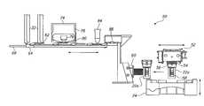
- FIG. 1is schematic front view of an automated specimen processing apparatus in accordance with one embodiment of the present invention
- FIG. 2is a schematic top plan view of the specimen processing apparatus depicted in FIG. 1;
- FIG. 3is a schematic front view of an identification correlation subsystem of a specimen processing apparatus in accordance with one embodiment of the present invention
- FIG. 4is a schematic top plan view of the identification correlation subsystem of a specimen processing apparatus depicted in FIG. 3;
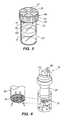
- FIG. 5is a schematic perspective view of a capped sample vial in accordance with one embodiment of the present invention.
- FIG. 6is a schematic perspective view of a sample collector during cell collection in accordance with one embodiment of the present invention.
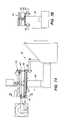
- FIG. 7Ais a schematic side view of a pre-contact condition of a sample collector approaching a specimen slide
- FIG. 7Bis a partial schematic cross-sectional view of the apparatus depicted in FIG. 7A taken along line 7 B— 7 B.
- FIG. 7Cis a schematic side view of an initial contact condition for a sample collector contacting a specimen slide
- FIG. 7Dis a schematic side view of a full contact condition of a sample collector contacting a specimen slide
- FIG. 8is a schematic perspective view of a rotatable interface for mating with a torque pattern of a sample vial cap
- FIG. 9Ais a schematic perspective view of a unidirectional interface in a sample vial tray for mating with anti-rotation features of a sample vial body.
- FIG. 9Bis a schematic perspective view of a bi-directional interface for mating with anti-rotation features of a sample vial body.
- FIGS. 1 and 2are schematic front and top plan views of an automated specimen preparing system 10 for preparing a plurality of specimens from a plurality of fluid samples.
- the system 10may be mounted on a wheeled instrument cart 12 for portability.
- the system 10includes a specimen preparing apparatus 18 or transferrer, functionally of the type disclosed in the aforementioned patents subject to improvements discussed further hereinbelow.
- the specimen preparing apparatus 18includes subassemblies for automatically dispersing, collecting, and transferring a monolayer of cells to an analytical element, such as a microscope slide.
- the particular structural details of the specimen preparing apparatus 18may vary from those disclosed in the aforementioned patents.
- the system 10includes a first loading station 20 for receiving a plurality of patient samples, each disposed in a sample vial 22 , as best seen in FIG. 5 .
- the sample vial loading station 20may have more than one tier to accommodate multiple sample vial trays 24 , two trays 24 being shown.
- Each tray 24is removable to facilitate handling and preloading of the vials 22 .
- each tray 24may include locations for forty samples vials 22 , providing a system 10 that can automatically process up to eighty samples without operator intervention. For a system 10 with a process cycle time of about ninety seconds per sample, eighty samples can be processed in about two hours of continuous, unattended operation.
- the system 10also includes a second loading station 26 for receiving a plurality of sample collectors 28 disposed in a sample collector tray 30 .
- each sample collector 28has a porous membrane or filter 29 at one end thereof against which cells are collected.
- the sample collector loading station 26may have more than one tier to accommodate multiple sample collector trays 30 , two trays 30 being shown. Each tray 30 is removable to facilitate handling and preloading of the sample collectors 28 .
- each tray 20may include locations for one hundred sample collectors 28 , providing a system 10 which can automatically process the eighty samples without operator intervention.
- the collectors 28may also be provided to the operator preloaded in the collector tray 30 , which may be reusable or discardable, as desired.
- Both loading stations 20 , 26include elevators for raising and lowering the trays 24 , 20 , as required, so that sample vial and collector transfer assemblies can access, respectively, each of the sample vials 22 and collectors 28 .
- Blank glass microscope slidesare preloaded in two removable cartridges 32 , each with the capacity to hold one hundred slides. Two cartridges 32 are provided to ensure that there are a sufficient number of slides available in the system 10 to process the maximum number of sample vials 22 . While glass microscope slides are typically used for preparing cytological specimens, other analytical elements, such as natural or synthetic material assay strips and the like, are suitable for other analyses and testing, as known by those skilled in the art, and could be employed in the system 10 with suitable handling equipment.
- One or more staining racks 34may be provided in an unloading area 36 of the system 10 to receive the slides once the cytological specimens have been transferred thereto.
- four staining racks 34are provided, each with a capacity of twenty slides. Accordingly, eighty sample vials 22 can be processed without having to remove the staining racks 34 .
- Staining rack adaptorsmay be provided so that the staining racks 34 can be loaded into automated, commercially available cytological specimen stainers after removal from the system 10 . Accordingly, prepared specimens can be efficiently and rapidly unloaded from the system 10 and the specimens stained with minimal manual intervention.
- a fixitive solutionmay be applied to the specimen at a coating station 38 .
- the coating station 38includes a fixitive reservoir 40 which holds the solution used to fix or preserve the specimen on the slide after preparation by the system 10 .
- the reservoirhas sufficient capacity to allow at least a day and preferably a week of average usage without the need for refilling or replacement.
- the fixitivemay be applied to the specimen by an air brush technique in which the fixitive solution is gently sprayed on the specimen so as not to disturb the spatial distribution of the cells on the slide.
- an airbrush having a generally conical spray distribution patternmay be used to apply a substantially uniformly dense layer of fixitive solution to a generally circular cell transfer area on the slide.
- a fine mistmay be applied in one or more short duration bursts to prevent displacing a monolayer of cells on the slide, typically using a very small volume of fluid dispensed from the airbrush using very low differential air pressure.
- each burstmay apply about 20 ⁇ 2 ⁇ l of fixitive solution over a period of about 0.6 seconds.
- a slight positive pressuremay be maintained in the reservoir 40 to compensate for any pressure head, thereby maintaining control of the dispensed volume per burst.
- the airbrushmay be of any conventional design capable of handling the small volumes applied and capable of providing the desired uniform conical spray distribution pattern.
- an airbrush nozzle, needle valve, and bodyare employed, with flow being controlled by an external valve, rather than a trigger valve typically supplied with the airbrush.
- the pressure source applied to the airbrushmay be calibrated and maintained at a fixed pressure in order to ensure a predetermined fixative flow rate for a particular airbrush, thereby achieving the desired dispensed volume per burst.
- a waste bottle 42is provided in fluidic communication with the specimen preparing apparatus 18 so that waste fluid can be drained during specimen preparation.
- the waste bottle 42may be mounted to an interior of the front door 16 to facilitate removal and replacement of the bottle 42 for emptying.
- a waste bin 44may also be provided to catch used sample collectors 28 .
- the porous membrane or filter 29 of each collector 28may be breached so that the collector 28 cannot be reused and possibly contaminate another specimen.
- the membrane 29may be breached by any of a variety of methods.
- the collector 28may be overpressurized, pneumatically with air or hydraulically with fluid, so as to burst the membrane.
- the membrane 29can be mechanically ruptured, for example, by impressing the membrane 29 on a sharp object, such as a pointed protrusion or knife edge mounted in the system 10 .
- the membranemay have a pore size on the order of about ten microns or less.
- a computer controller or processor 46is provided to communicate with and coordinate operation of the various sensors and components of the system 10 to permit automatic, unattended operation during specimen preparation.
- the processor 46includes an appropriate operator interface 47 with associated input keypad or buttons and an output display, such as a liquid crystal diode display.
- Instructions, prompts, and error messagesmay be in text, error code, or symbol formats.
- Text displaysmay be in a variety of operator selectable languages, such as English, French, German, Italian, Japanese, and Spanish.
- Audible outputs corresponding to operator prompts, error conditions, keypad inputs, and completion of automatic processingmay be provided.
- a thermal paper printer 48 or other type of printermay be provided, as well, to generate a permanent paper record of system operation and sample processing.
- the printer 48may generate a report containing the date and time processing began, a listing of the sample vials 22 not successfully processed (including error type and tray location), and a listing of the sample vials 22 successfully processed (including sample identification information and tray location).
- an identification correlation subsystem 50is provided in combination with a specimen transfer assembly of the system 10 , as depicted schematically in front and top plan views in FIGS. 3 and 4, respectively.
- a sample vial transfer assembly 52in order to prepare a specimen from a sample vial 22 , a selected capped vial 22 a is removed from one of the sample vial trays 24 by a sample vial transfer assembly 52 .
- the vial transfer assembly 52includes a four-fingered gripper 54 configured to reliably and repeatable grasp a cap 56 of the vial 22 a.
- the vial transfer assembly 52is movable about a plane above the vial tray 24 , left to right and into and out of the drawing as depicted in FIG. 3, so that the gripper 54 can be aligned above any of the forty vials 22 loaded in the tray 24 .
- the tray 24is raised by the tray elevator, the vial cap 56 grasped by the gripper 54 and tightened as will be discussed in greater detail hereinbelow, and the tray 24 lowered.
- the vial transfer assembly 52can be retracted to one side, outside a footprint of the trays 24 and the tray elevator operated to raise or lower the tray 24 , as necessary. Similar handling is provided for the sample collectors 28 and collector trays 30 using a transfer assembly and an elevator, respectively.
- Each vial 22includes identifying indicia, such as a bar code label 58 mounted thereon, which corresponds to and uniquely identifies the vial 22 and the sample contained therein.
- the selected vial 22 ais then presented by the vial transfer assembly 52 to an identifier, such as a laser scanner bar code reader 60 , so that the particular vial 22 a can be identified. Because the circumferential orientation of the vials 22 in each tray 24 and that of the respective bar code labels 58 can vary, upon presentation to the bar code reader 60 , the vial transfer assembly 52 rotates the sample vial 22 a about a vertical axis passing generally through an axial centerline thereof, as best seen in FIG. 4, to present the label 58 to the reader 60 .
- the processor 46directs the preparation of an analytical element, such as a microscope slide 62 , for receipt of a specimen from the selected vial 22 a.
- the specimen transfer assemblycan include a slide carriage 64 , translatable along a carriage rail 66 , that first extracts a slide 62 from one of the slide cartridges 32 .
- Each slide 62has tightly toleranced dimensions and chamfered edges to facilitate handling and transfer of the slide 62 by the components of the system 10 and minimize the likelihood of mishandling or jamming.
- the slide 62is manufactured from glass and has a width of about one inch, a length of about three inches, and a thickness of about 0.04 inches.
- One end 68 of the slide 62is frosted or coated to facilitate marking, as will be discussed in greater detail hereinbelow.
- the frosted end 68may have an area of about one square inch.
- a frosted annulus 70defining an area to where the cells are transferred, may also be provided to facilitate manual or automatic scanning of sparse specimens.
- the bounded specimen areamay have an area of about one square inch, substantially equivalent to the surface area of the membrane 29 .
- one corner 72 of the frosted end 68 of each slide 62may be chamfered to a greater degree than the other corners to ensure proper orientation of the slide 62 in the slide cartridge 32 and proper presentation of the slide 62 to downstream components.
- the slide carriage 64conveys the slide 62 to a marker in communication with the processor 46 for marking the slide 62 with indicia corresponding to the sample indicia on the bar code label 58 .
- the markermay be a printer 74 , such as an ink jet printer, thermal printer, laser printer, or other suitable marker capable of producing substantially permanent indicia on the slide 62 .
- the printer 74is a dot matrix impact printer utilizing a multi-pin impact head 76 and replaceable ribbon cartridge 78 , which feeds an ink ribbon 80 to a zone between the impact head 76 and the slide 62 .
- the processor 46next directs the printer 74 to mark the slide 62 .
- the slide indiciamay have any of a variety of forms including one or more alphanumeric characters, as shown generally at 82 . It is generally desirable to mark the slides 62 with man-readable indicia so that the cytologist examining a fixed, stained specimen can readily identify the specimen and associated sample from which the specimen was prepared. Further, specimens are often archived and retained for extended periods. Accordingly, it is generally desirable to avoid using an indicia standard that may fall into disuse or become obsolete. While the slide indicia may be marked on an adhesive label bonded to the slide 62 , subsequent processing such as fixing and staining may degrade the indicia or bond.
- slide indicia 82be oriented along the width or narrow dimension of the frosted end 68 so as to be readable without requiring removal of the slide 62 from the file drawer.
- the slide indicia printing method and printing mediashould be resistant to the solvents used in the specimen preparing, fixing, and staining processes.
- Typical solventsinclude ethanol, methanol, xylene, water, and a clarifier solution consisting of 0.025% glacial acetic acid in distilled water.
- commercially available carbon black based printing ink ribbons 80have been found to perform well when printing on frosted ends 68 produced by coating the ends of the slides 62 with a white epoxy paint material.
- the processor 46may control operation of the printer 74 and the slide carriage 64 so as to first transfer a spot of ink to a first location on the slide 62 and then transfer another spot of ink to a second location offset spatially and slightly overlapping the first location.
- a relatively low cost nine pin dot matrix printercan produce alphanumeric characters substantially visually consistent with those produced by a much more expensive dot matrix printer having many more pins in the impact head.
- the processor 46directs the slide carriage 64 to advance the slide 62 along the carriage rail 66 to a reader in communication with the processor 46 for reading the slide indicia 82 .
- the readermay be an optical character recognition (OCR) scanner 84 or system.
- OCRoptical character recognition
- a total of four strikesare employed per pin using a nine pin printer in order to meet OCR font specifications typical for higher resolution dot matrix printers.
- the processor 46verifies both that the slide indicia 82 is readable by the OCR scanner 84 and that the slide indicia 82 corresponds to the sample indicia identified from the bar code label 58 on the selected vial 22 a.
- the slide 62may be removed automatically from the slide carriage 64 using an ejector or other apparatus, as discussed in greater detail hereinbelow, and discarded in the waste bin 44 or other waste receiving area. If multiple slides 62 fail in succession or if more than a predetermined number of slides fail during processing of a batch of sample vials 22 , the system 10 may be programmed optionally to halt automatic operation and alert the operator with a suitable error message.
- the sample vial transfer assembly 52removes the cap 56 from the sample vial 22 a so that the specimen preparing apparatus 18 can cycle.
- a sample collector 28is taken automatically from the collector tray 30 at the second loading station 26 and inserted into the specimen preparing apparatus 18 . Thereafter, the membrane 29 of the collector 28 is inserted into the specimen vial 22 a to a predetermined depth as shown in FIG. 6 and, in one embodiment, the collector 28 is rotated to disperse the cells in the preservative fluid.
- a vacuum system 88applies a controlled pressure and vacuum cycle to the collector 28 so that cells are collected in a monolayer against the membrane 29 . The cells are subsequently transferred to the zone within the frosted annulus 70 on the slide 62 as shown schematically in FIGS. 7A-C.
- the sample vial 22may be rotated prior to uncapping to disperse the cells in the preservative solution, as will be discussed in greater detail hereinbelow.
- the membrane 29 of the collector 28first contact the slide 62 generally at a single location, forming a predetermined small pre-contact angle between the substantially planar membrane 29 and a deposition surface of the slide 62 , and then gently and gradually enter into complete contact with the slide 62 .
- the specimen preparing apparatus 18inverts the collector 28 to drain any excess fluid therein into the waste bottle 42 mounted on the cart door 16 .
- the apparatus 18slowly elevates he membrane 29 to a position proximate the slide 62 , which is retained in an inverted orientation in a slide holder 90 hanging from two studs 92 captured by the slide carriage 64 .
- the holder 90 and the slide 62are positioned in an orientation which is slightly offset from horizontal.
- FIG. 7Bis a partial schematic cross-sectional view of the specimen preparing apparatus 18 and slide holder 90 depicted in FIG. 7A, taken along line 7 B— 7 B.
- two pre-adjusted jack screws 94first contact the slide holder 90 at one end thereof.
- the holder 90achieves a more horizontal orientation due to contact with the jack screws 94 until an edge of the membrane 29 , shown generally at 29 a in FIG. 7C, contacts the slide 62 .
- the angle formed between the membrane 29 and the slide 62may be on the order of several degrees or less, typically 0.75 ⁇ 0.25 degrees.
- the cells captured therebetweencan be readily transferred, for example with minimal positive pressurization of the collector 28 which slightly bows the membrane into a convex configuration.
- a fixitive solutionmay then be applied to the transferred specimen and the slide 62 transferred from the slide carriage 64 to one of the staining racks 34 at the unloading area 36 using a slide transfer assembly such as a translating slide ejector 86 .
- the slide ejector 86 and/or the unloading area 36may include automatic height and side-to-side translation capability, so as to be able to accept the prepared specimen slide 62 in a next open slot in any one of the plurality of staining racks 34 .
- the membrane 29 of the used collector 28is breached and the collector 28 discarded in the waste bin 44 .
- the cap 56is replaced on the sample vial 22 a and the vial 22 a returned to its location in the vial tray 24 . If there exist additional sample vials 22 which have not yet been processed, a next vial 22 is removed automatically, the sample indicia identified, and a next specimen prepared therefrom according to the steps described hereinabove.
- each vial 22 and cap 56includes one or more structural features which facilitate grasping of the closed, capped vial 22 by the sample vial transfer ssembly 52 , as well as removal and reinstallation of the cap 56 .
- the sample vial 22includes a body 23 having a generally cylindrical outer surface, an open end, a closed end, and at least one lug 25 disposed about the outer surface. The lug 25 performs an anti-rotation function, preventing the body 23 from rotating when disposed against adjacent structure.
- the sample vial cap 56is releasably engagable with the body 23 , the cap 56 including an outer surface with a torque pattern 27 thereon for mating with a rotatable interface of the sample vial transfer assembly 52 as discussed more fully hereinbelow.
- a sealis disposed between the body 23 and the cap 56 so as to be capable of forming a substantially fluid-tight seal therebetween.
- the body 23may include a plurality of lugs disposed about a perimeter of the body 23 , such as the six equi-spaced lugs 25 of the embodiment of FIG. 5 . While the lugs 25 may be disposed anywhere on the body 23 accessible to the sample vial transfer assembly 52 or related structure of the system 10 , the lugs 25 may be disposed advantageously proximate the open end of the body 23 and the cap 56 . In this manner, torque may be applied to both the body 23 and the cap 56 at approximately the same axial plane to minimize any induced moment in the vial 22 during removal and installation of the cap 56 .
- the sample vial body 23may be manufactured from a substantially transparent or translucent material so that a level of the fluid sample therein can be readily discerned by the system operator to ensure the presence of a sufficient amount of fluid for subsequent processing.
- the body 23may also include fluid level indicia 31 disposed on the outer surface thereof, such as a circumferentially-disposed frosted annular band. Accordingly, the vials 22 can be rapidly visually screened by the operator prior to loading in the vial tray 24 to prevent loading a vial 22 with too much or too little fluid which might not be processed successfully by the specimen preparing apparatus 18 .
- the fluid level indicia 31may be provided in addition to the sample bar code label 58 discussed hereinabove.
- the capmay be manufactured from polypropylene or other suitable material and may include knurling 33 or other anti-slip feature along an outer perimeter thereof to facilitate manual handling by a nurse or doctor during sample procurement, as well as the system operator during manual loading and loading of the sample vial trays 24 .
- the cap torque pattern 27may be at least one generally radially disposed rib 35 . In the embodiment depicted in FIG. 5, the torque pattern 27 includes six generally radially disposed, equi-spaced ribs 35 .
- the sealmay be manufactured from any suitable material which can be sterilized and which is capable of withstanding attack by the preservative fluid, which may typically contain a solution of methanol in a buffer.
- the sealmay be manufactured from a multicomposite material such as a resilient rubber layer laminated with a suitable vapor barrier and may be disposed within the cap 56 .
- the cap 56 and the body 23may have mating screw threads, a bayonet fitting, or other retention feature so as to be releasably engageable.
- a substantially fluid-tight seal between the body 23 and the cap 56may be formed when at least between about 5 and 50 inch-pounds of torque is applied to the cap 56 relative to the body 23 .
- each of the cap 56 and the body 23may include alignment markers 37 , 39 , such that the alignment markers 37 , 39 indicate a fluid-tight seal when at least aligned.
- FIG. 8is a schematic perspective view of one design of a rotatable interface 142 disposed radially inwardly of the grippers 54 of the vial transfer assembly 52 .
- the interface 142includes a torque pattern 144 for mating with the torque pattern 127 of the sample vial cap 56 .
- the rotatable interface 142is shown inverted, to better depict the interface torque pattern 144 formed therein.
- the interface torque pattern 144includes six raised wedge-shaped sectors 146 .
- the sectors 146are substantially equi-spaced about the interface 142 , which is rotatable about a longitudinal axis 148 thereof, and sized to mate with the torque pattern 127 of the cap 56 . Accordingly, the ribs 35 of the cap 56 fit in grooves 150 formed between the sectors 146 of the interface 142 and react against substantially vertical faces of the sectors 146 to permit both loosening and tightening of the cap 56 .
- the body 23may be disposed in a bore 152 formed in the sample vial tray 24 having a unidirectional interface 154 along an edge 160 thereof for mating with the lugs 18 of the body 23 , as depicted in FIG. 9 A.
- the interface 154includes six ramps 156 , each including a substantially vertical face 158 which abuts one of the body lugs 25 .
- the capped vial 22may be disposed in the bore 152 with a flange 140 of the body 23 supported along the edge 160 .
- the rotatable interface 142may then be engaged with and tighten the cap 56 , to ensure a fluid-tight seal prior to removing the vial 22 from the sample tray 24 . Due to the orientation of the ramps 156 , the lugs 25 react against the ramp faces 158 during tightening to positively secure and prevent rotation of the vial body 23 .
- the vial transfer assembly 52may grasp the capped vial 22 about the circumference of the cap 56 with the grippers 54 , remove the vial 22 from the bore 152 in the tray 24 , rotate the vial 22 in front of the bar code reader 60 , and deposit the capped vial 22 in a bore 162 formed in a vial sleeve 164 , such as that depicted in FIG. 9B in wire form representation.
- the six lugs 25 of the capped vial 22are received in every other one of twelve axially extending slots 166 formed along an upper edge 168 of the sleeve 164 , the flange 140 of the vial 22 being supported by the edge 168 .
- a slide 62is printed and the slide indicia 82 verified as being readable and corresponding to the vial bar code label 58 .
- the vial 22may then be uncapped and the sample collector 28 can be disposed in the vial 22 and rotated to disperse the cells in the sample.
- the sleeve 164may be rotated in one or both directions to disperse the cells in the preservative solution.
- a pin, clamp, or other structural feature of the system 10may engage one of a series of notches 170 formed in a flange 172 of the sleeve 164 to prevent rotation of the sleeve 164 and the vial 22 disposed therein while the rotatable interface 142 engages and unscrews the cap 56 .
- the cap 56is then retracted by the gripper 54 of the vial transfer assembly 52 and the sample collector 28 disposed in the preservative solution in the vial 22 to collect the cells against the filter 29 thereof and thereafter transfer the cells to the slide 62 .
- the cap 56is reoriented over the open vial 22 and screwed onto the body 23 until a substantially fluid-tight seal has been formed.
- the axially extending slots 166which engage the lugs 25 form a bi-directional interface, to react against the body lugs 25 during both removal and installation of the cap 56 on the body 23 .
- Each of the axial slots 166may be formed to include, optionally, a generally circumferentially disposed portion, shown generally at 174 , to lock a suitably sized lug against axial translation, if desired.
- the body 23 , the cap 56 , the ribs 35 , the lugs 25 , the fluid level indicia 31 , and other features of the sample vial 22will be apparent to those skilled in the art, those disclosed being provided as examples only.
- the mating ribs 35 and sectors 146provide a positive, self-centering drive, other mating structure such as pins and annular tracks may be used.
- the sample vial 22may be used in other applications and contain other than cytological samples in preservative solution.
- the automated specimen preparing system 10 described hereinemploys certain specimen preparing innovations disclosed in the aforementioned patents in combination with batch processing capability to prepare gynecological and other cytological specimens in a highly efficient, reliable manner.
- the system 10may also be used to batch process other specimens such as those including tissue samples, assay products, and other materials.
- Industry and regulatory acceptance of a system 10 and method in accordance with the teachings set forth hereinare based, in part, on the capability to maintain one-to-one correlation between a patient sample and a specimen produced therefrom.
- a specimenis not produced on an unmarked slide 62 , or on a slide 62 on which the specimen indicia are not readable or do not correlate with the sample indicia bar code label 58 identified from the selected vial 22 a.
- a preprinted bar code label 58 with a unique accession numberis applied to the sample vial 22 .
- a second matching bar code label 58is applied to a patient information sheet, listing relevant patient identifying information, as well as information regarding the tests or analyses to be performed on the specimen prepared from the sample. Accordingly, when data from the patient information sheet is entered into a database at a sample receiving area in a cytological laboratory, data from the bar code label 58 on the patient information sheet can also be input, either manually or preferably automatically using a laser scanner. The specimen produced from the sample with the matching bar code will therefore readily be identifiable as being from a particular patient.
- the system 10runs in an automated manner under control of the processor 46 until all sample vials 22 are processed, or until such time as a system malfunction occurs or a consumable, such as a sample collector 28 or slide 62 , is depleted.
- sensorsare provided throughout the system 10 to verify the presence of sufficient consumables to process all loaded samples prior to the initiation of automatic operation. Sensors may also be provided to monitor levels in the waste bottle 42 and waste bin 44 , so that the operator can be alerted to elevated levels of waste, which could interrupt processing during automatic cycling.
- the system 10checks that sample vials 22 are loaded and a minimum number of necessary consumables and staining racks are available to complete processing of all the samples. If sufficient consumables and waste capacities exist, the system 10 starts the automatic sample processing cycle. The cycle continues until all of the loaded sample vials 22 have been processed, the operator manually interrupts the cycle, or a system error occurs which cannot be automatically rectified. If insufficient consumables or waste capacities exist, the operator may correct the condition or, alternatively, override the system 10 and initiate automatic processing anyway.
- Start Batchmay be used to resume automatic cycling at the point of interruption, after checking system consumables and capacities.
- access pointssuch as the upper cover 14 may be interlocked.
- the operatormay select “Interrupt Batch.”
- the processor 46interrupts the automatic cycle in an orderly manner, for example, by completing preparation of a specimen in process, transferring the completed specimen slide 62 to a staining rack 34 in the unloading area 36 , and capping and returning the selected sample vial 22 a to the vial tray 24 .
- the operator access interlocksare unlatched and the operator is notified. The operator may then open the upper cover 14 or access other internal areas of the system 10 , as desired.
- a “Maintenance” functioncan also be provided in which the system 10 supports operator level maintenance activities such as jogging of the moving components to or from respective home positions to provide the operator access to various interior volumes of the system 10 , for example, to clear ajam or to retrieve a mishandled slide 62 .
- Other maintenance functionsmay include emptying of the waste bottle 42 and bin 44 , priming of the fixitive coating station 38 with the fixitive solution, and advancing of paper in the system printer 48 .
- the system 10may also provide operator selectable diagnostic tests to facilitate system troubleshooting or verify proper system operation. For example, a pneumatic test may be initiated of the vacuum system 88 of the specimen preparing apparatus 18 to ensure sufficient volumetric flow rate and negative pressure level. A display test could be used to verify display operation.
- a usage logmay be provided to track total number of samples processed, total number of specimens produced, total system run time, and other relevant usage parameters.
- the processor 46may also maintain an error log which lists, for example, the last fifty errors detected by the system 10 and which may be displayed or printed at the discretion of the operator.
- a typical log entrymay include date and time of the error, sample indicia and tray location, and disposition or corrective action.
- the system 10identifies any sample vial 22 from which a specimen was not successfully prepared, along with the reason for the failure, such as “sample too dense” or “cap too tight.”
- Detectable conditions that could cause specimen quality problemsare flagged by the system 10 and noted to the operator on the display and paper printout. If possible, a partially collected specimen is returned to the vial 22 and preparation of the slide 62 is aborted. If the problem is associated with a particular selected sample vial 22 a, the system 10 recovers after returning the selected vial 22 a to the vial tray 24 and recording the error, processing the remaining sample vials 22 in the batch. However, if the error is a system level problem, such as a motor or sensor failure, jammed mechanism, or other malfumction that is not automatically recoverable and requires operator or qualified service personnel intervention, the automatic cycle is halted and the error recorded and reported to the operator.
- a system level problemsuch as a motor or sensor failure, jammed mechanism, or other malfumction that is not automatically recoverable and requires operator or qualified service personnel intervention
- the processor 46may be initialized and setup functions enabled or disabled. For example, the date and time may be input, as well as the respective formats thereof.
- the system printer 48may be directed to automatically print diagnostic test results or sample processing data at the end of every automatic batch cycle.
- a date/time stampmay be enabled to print the date and time a specimen was prepared on the frosted end 68 of each slide 62 , in addition to the slide indicia 82 .
- the name or other identifier of the cytological laboratory preparing the specimen with the system 10may be printed on the slide 62 as well.
- the system 10 and methodcould be programmed to permit two or more specimens to be prepared from a single sample vial 22 .
- the slide indicia 82could include an additional character or identifier to indicate the first specimen, second specimen, third specimen, etc.
- the sample vial 22could be reprocessed by inserting the vial 22 in a tray 24 in a next batch for a subsequent automatic cycle.
- the disclosed components of the system 10may be manufactured in various sizes, configurations, and materials. Additionally, the system 10 may be used to prepare specimens from non-gynecologic cytological samples, such as cells sourced from fine needle aspirates, from mucoid specimens taken from respiratory and gastrointestinal tracts, from body fluids such as serous effusions and urinary and cerebrospinal fluids, from superficial brushings and scrapings from oral cavities, nipple secretions, skin lesions, and eye brushings, and from other sources.
- non-gynecologic cytological samplessuch as cells sourced from fine needle aspirates, from mucoid specimens taken from respiratory and gastrointestinal tracts, from body fluids such as serous effusions and urinary and cerebrospinal fluids, from superficial brushings and scrapings from oral cavities, nipple secretions, skin lesions, and eye brushings, and from other sources.
Landscapes
- Health & Medical Sciences (AREA)
- Chemical & Material Sciences (AREA)
- Life Sciences & Earth Sciences (AREA)
- Analytical Chemistry (AREA)
- General Health & Medical Sciences (AREA)
- Immunology (AREA)
- Physics & Mathematics (AREA)
- Pathology (AREA)
- Biochemistry (AREA)
- Engineering & Computer Science (AREA)
- General Physics & Mathematics (AREA)
- Molecular Biology (AREA)
- Clinical Laboratory Science (AREA)
- Chemical Kinetics & Catalysis (AREA)
- Organic Chemistry (AREA)
- Biomedical Technology (AREA)
- Wood Science & Technology (AREA)
- Zoology (AREA)
- Proteomics, Peptides & Aminoacids (AREA)
- Hematology (AREA)
- Biophysics (AREA)
- Genetics & Genomics (AREA)
- General Engineering & Computer Science (AREA)
- Bioinformatics & Cheminformatics (AREA)
- Microbiology (AREA)
- Biotechnology (AREA)
- Sampling And Sample Adjustment (AREA)
Abstract
Description
Claims (12)
Priority Applications (21)
| Application Number | Priority Date | Filing Date | Title |
|---|---|---|---|
| US09/521,531US6562299B1 (en) | 1998-09-18 | 2000-03-08 | Method and apparatus for preparing cytological specimens |
| AU4551601AAU4551601A (en) | 2000-03-08 | 2001-03-08 | Method and apparatus for preparing cytological specimens |
| AU2001245516AAU2001245516B2 (en) | 2000-03-08 | 2001-03-08 | Method and apparatus for preparing cytological specimens |
| PCT/US2001/007418WO2001067067A2 (en) | 2000-03-08 | 2001-03-08 | Method and apparatus for preparing cytological specimens |
| HK03103815.4AHK1051570B (en) | 2000-03-08 | 2001-03-08 | Method and apparatus for preparing cytological specimens |
| EP01918438.1AEP1261852B2 (en) | 2000-03-08 | 2001-03-08 | Method and apparatus for preparing cytological specimens |
| EP01916485AEP1261851B1 (en) | 2000-03-08 | 2001-03-08 | Method and apparatus for preparing cytological specimens |
| JP2001565990AJP4846161B2 (en) | 2000-03-08 | 2001-03-08 | Method and apparatus for preparing cytological specimens |
| PCT/US2001/007377WO2001067066A2 (en) | 2000-03-08 | 2001-03-08 | Method and apparatus for preparing cytological specimens |
| ES01916485TES2269369T3 (en) | 2000-03-08 | 2001-03-08 | METHOD AND APPARATUS TO PREPARE CYTOLOGICAL SPECIMENS. |
| AU2001243505AAU2001243505B2 (en) | 2000-03-08 | 2001-03-08 | Method and apparatus for preparing cytological specimens |
| DE60121919TDE60121919T2 (en) | 2000-03-08 | 2001-03-08 | METHOD AND DEVICE FOR PREPARING CELL SAMPLES |
| HK03103816.3AHK1051892B (en) | 2000-03-08 | 2001-03-08 | Method and apparatus for preparing cytological specimens |
| JP2001565991AJP4637436B2 (en) | 2000-03-08 | 2001-03-08 | Method and apparatus for preparing cytological specimens |
| AU4350501AAU4350501A (en) | 2000-03-08 | 2001-03-08 | Method and apparatus for preparing cytological specimens |
| AT01916485TATE335196T1 (en) | 2000-03-08 | 2001-03-08 | METHOD AND DEVICE FOR PREPARING CELL SAMPLES |
| US10/421,549US7579190B2 (en) | 1998-09-18 | 2003-04-22 | Method and apparatus for preparing cytological specimens |
| US10/421,480US7435599B2 (en) | 1998-09-18 | 2003-04-22 | Method and apparatus for preparing cytological specimens |
| US12/465,032US8574912B2 (en) | 1998-09-18 | 2009-05-13 | Method and apparatus for preparing cytological specimens |
| US14/068,158US20140057347A1 (en) | 1998-09-18 | 2013-10-31 | Method and apparatus for preparing cytological specimens |
| US14/292,730US9448146B2 (en) | 1998-09-18 | 2014-05-30 | Method for automated specimen transfer |
Applications Claiming Priority (2)
| Application Number | Priority Date | Filing Date | Title |
|---|---|---|---|
| US09/156,952US20030059347A1 (en) | 1998-09-18 | 1998-09-18 | Sample vial for use in preparing cytological specimen |
| US09/521,531US6562299B1 (en) | 1998-09-18 | 2000-03-08 | Method and apparatus for preparing cytological specimens |
Related Parent Applications (2)
| Application Number | Title | Priority Date | Filing Date |
|---|---|---|---|
| US09/156,952Continuation-In-PartUS20030059347A1 (en) | 1998-09-18 | 1998-09-18 | Sample vial for use in preparing cytological specimen |
| US09/520,421Continuation-In-PartUS6572824B1 (en) | 1998-09-18 | 2000-03-08 | Method and apparatus for preparing cytological specimens |
Related Child Applications (3)
| Application Number | Title | Priority Date | Filing Date |
|---|---|---|---|
| US09/520,421Continuation-In-PartUS6572824B1 (en) | 1998-09-18 | 2000-03-08 | Method and apparatus for preparing cytological specimens |
| US10/421,549ContinuationUS7579190B2 (en) | 1998-09-18 | 2003-04-22 | Method and apparatus for preparing cytological specimens |
| US10/421,480Continuation-In-PartUS7435599B2 (en) | 1998-09-18 | 2003-04-22 | Method and apparatus for preparing cytological specimens |
Publications (1)
| Publication Number | Publication Date |
|---|---|
| US6562299B1true US6562299B1 (en) | 2003-05-13 |
Family
ID=46279624
Family Applications (5)
| Application Number | Title | Priority Date | Filing Date |
|---|---|---|---|
| US09/521,531Expired - LifetimeUS6562299B1 (en) | 1998-09-18 | 2000-03-08 | Method and apparatus for preparing cytological specimens |
| US10/421,549Expired - Fee RelatedUS7579190B2 (en) | 1998-09-18 | 2003-04-22 | Method and apparatus for preparing cytological specimens |
| US12/465,032Expired - Fee RelatedUS8574912B2 (en) | 1998-09-18 | 2009-05-13 | Method and apparatus for preparing cytological specimens |
| US14/068,158AbandonedUS20140057347A1 (en) | 1998-09-18 | 2013-10-31 | Method and apparatus for preparing cytological specimens |
| US14/292,730Expired - LifetimeUS9448146B2 (en) | 1998-09-18 | 2014-05-30 | Method for automated specimen transfer |
Family Applications After (4)
| Application Number | Title | Priority Date | Filing Date |
|---|---|---|---|
| US10/421,549Expired - Fee RelatedUS7579190B2 (en) | 1998-09-18 | 2003-04-22 | Method and apparatus for preparing cytological specimens |
| US12/465,032Expired - Fee RelatedUS8574912B2 (en) | 1998-09-18 | 2009-05-13 | Method and apparatus for preparing cytological specimens |
| US14/068,158AbandonedUS20140057347A1 (en) | 1998-09-18 | 2013-10-31 | Method and apparatus for preparing cytological specimens |
| US14/292,730Expired - LifetimeUS9448146B2 (en) | 1998-09-18 | 2014-05-30 | Method for automated specimen transfer |
Country Status (1)
| Country | Link |
|---|---|
| US (5) | US6562299B1 (en) |
Cited By (25)
| Publication number | Priority date | Publication date | Assignee | Title |
|---|---|---|---|---|
| US20030207456A1 (en)* | 1998-09-18 | 2003-11-06 | Cytyc Corporation | Method and apparatus for preparing cytological specimens |
| US20060029519A1 (en)* | 2004-06-30 | 2006-02-09 | Masanori Nakaya | Specimen preparation apparatus, specimen preparation/analysis system and specimen plate |
| US20060161076A1 (en)* | 2005-01-06 | 2006-07-20 | Diamics, Inc. | Systems and methods for collection of cell clusters |
| US20060189893A1 (en)* | 2005-01-06 | 2006-08-24 | Diamics, Inc. | Systems and methods for detecting abnormal cells |
| US20060210432A1 (en)* | 2005-03-08 | 2006-09-21 | Cytyc Corporation | Specimen vial cap handler and slide labeler |
| US20070141711A1 (en)* | 2005-12-19 | 2007-06-21 | Randy Stephens | Automated lean methods in anatomical pathology |
| US20070292315A1 (en)* | 2006-06-16 | 2007-12-20 | Cytyc Corporation | Mini-tray for slide processing |
| US20080019880A1 (en)* | 2006-07-21 | 2008-01-24 | Cytyc Corporation | Tray for slide processing |
| US20080095672A1 (en)* | 2006-10-18 | 2008-04-24 | Cytyc Corporation | Filter for automated slide preparation system |
| US20080247914A1 (en)* | 2007-04-06 | 2008-10-09 | Ted Carl Edens | Sample Preparation System And Method for Processing Clinical Specimens |
| US20090275076A1 (en)* | 2008-05-02 | 2009-11-05 | Select Diagnostics, Inc. | Cell sample preparation method and apparatus |
| EP2164012A1 (en) | 2003-09-05 | 2010-03-17 | Cytyc Corporation | Locally storing biological specimen data to a slide |
| US20100080732A1 (en)* | 2008-09-26 | 2010-04-01 | Sysmex Corporation | Analyzer and liquid container |
| US20100093016A1 (en)* | 2008-10-10 | 2010-04-15 | Cytyc Corporation | Microfluidic apparatus and method for preparing cytological specimens |
| WO2012115948A1 (en) | 2011-02-22 | 2012-08-30 | Hologic, Inc. | Apparatus for preparing cytological specimens |
| US8703492B2 (en) | 2007-04-06 | 2014-04-22 | Qiagen Gaithersburg, Inc. | Open platform hybrid manual-automated sample processing system |
| CN104487819A (en)* | 2012-06-22 | 2015-04-01 | 生物辐射实验室股份有限公司 | Two station sample and washing system |
| US9075039B2 (en) | 2011-11-08 | 2015-07-07 | Becton, Dickinson And Company | Container and cap for a biological specimen |
| US9381524B2 (en) | 2011-11-08 | 2016-07-05 | Becton, Dickinson And Company | System and method for automated sample preparation |
| US9953141B2 (en) | 2009-11-18 | 2018-04-24 | Becton, Dickinson And Company | Laboratory central control unit method and system |
| WO2018093927A1 (en) | 2016-11-21 | 2018-05-24 | Hologic, Inc. | Wash solution and method to remediate lubricant contamination |
| WO2018165630A1 (en) | 2017-03-09 | 2018-09-13 | Hologic, Inc. | Systems and methods for automated preparation of biological specimens |
| WO2020091965A2 (en) | 2018-11-02 | 2020-05-07 | Hologic, Inc. | Digital imaging system and method |
| WO2021108321A1 (en) | 2019-11-25 | 2021-06-03 | Hologic, Inc. | Digital imaging system and method |
| US12392692B2 (en) | 2017-03-09 | 2025-08-19 | Hologic, Inc. | Systems for automated preparation of biological specimens |
Families Citing this family (29)
| Publication number | Priority date | Publication date | Assignee | Title |
|---|---|---|---|---|
| AUPP058197A0 (en)* | 1997-11-27 | 1997-12-18 | A.I. Scientific Pty Ltd | Pathology sample tube distributor |
| US7687032B2 (en) | 2004-05-06 | 2010-03-30 | Cytyc Corporation | Filter assembly for molecular testing |
| WO2007047131A1 (en)* | 2005-10-11 | 2007-04-26 | Cytyc Corporation | Methods and materials for fixing cytological samples |
| US20070128668A1 (en)* | 2005-12-01 | 2007-06-07 | Larry Burg | Quantitative use of tracer cells |
| CN100410652C (en)* | 2006-01-12 | 2008-08-13 | 上海交通大学 | A teaching kit for biological evolution at the cellular level |
| CN100410651C (en)* | 2006-01-12 | 2008-08-13 | 上海交通大学 | A teaching kit for the indication of environmental pollution by broad bean micro-nucleus |
| US20080009072A1 (en)* | 2006-07-07 | 2008-01-10 | Cytyc Corporation | Ultrasonic mixing of a biological sample |
| US9602777B2 (en) | 2008-04-25 | 2017-03-21 | Roche Diagnostics Hematology, Inc. | Systems and methods for analyzing body fluids |
| WO2012030313A1 (en) | 2008-04-25 | 2012-03-08 | James Winkelman | Method of determining a complete blood count and a white blood cell differential count |
| SG10201403755RA (en) | 2009-10-19 | 2014-10-30 | Ventana Med Syst Inc | Imaging System And Techniques |
| AU2013205438B2 (en)* | 2009-10-19 | 2014-10-16 | Ventana Medical Systems, Inc. | Imaging system and techniques |
| US20110151505A1 (en)* | 2009-12-16 | 2011-06-23 | Girees Sherif K | Substance for Specimen Preparations and Related Methods |
| FR2957672B1 (en) | 2010-03-22 | 2013-03-15 | Novacyt | AUTOMATIC METHOD AND AUTOMATE FOR PREPARING AND ANALYZING A PLURALITY OF CELLULAR SUSPENSIONS |
| WO2012036867A2 (en) | 2010-09-13 | 2012-03-22 | Primera Technology, Inc. | Histological specimen cassette |
| US9254639B2 (en) | 2010-09-13 | 2016-02-09 | Primera Technology, Inc. | Cartridge for histological specimen slides |
| KR20140071281A (en)* | 2011-05-18 | 2014-06-11 | 테크노 메디카 캄파니 리미티드 | Automatic preparation system for blood collection tube |
| EP2734824B1 (en) | 2011-07-22 | 2019-01-23 | Roche Diagnostics Hematology, Inc. | Fluid sample preparation systems and methods |
| JP6097297B2 (en) | 2011-09-09 | 2017-03-15 | ジェン−プローブ・インコーポレーテッド | Automatic sample manipulation instrument, system, process, and method |
| US9007411B2 (en) | 2012-09-19 | 2015-04-14 | Primera Technology, Inc. | Reverse transfer color printers for histological specimen slides and cassettes |
| US20140193848A1 (en) | 2013-01-09 | 2014-07-10 | Hologic, Inc. | Sample vial cap and sample vial for use in preparing cytological specimen and method of preparing cytological specimen |
| US9001422B2 (en) | 2013-02-28 | 2015-04-07 | Ventana Medical Systems, Inc. | Slide handling system and techniques |
| CN114851716B (en) | 2014-10-21 | 2024-06-04 | 简·探针公司 | Method and apparatus for printing on object having curved surface |
| JP7120922B2 (en) | 2016-02-17 | 2022-08-17 | ベクトン・ディキンソン・アンド・カンパニー | Automated sample preparation system for diagnostic testing of samples |
| ES2972583T3 (en) | 2016-04-22 | 2024-06-13 | Becton Dickinson Co | Automated diagnostic analyzer and method for its operation |
| CN207067156U (en) | 2016-04-22 | 2018-03-02 | 贝克顿·迪金森公司 | automated diagnostic analyzer |
| CN108792121A (en)* | 2018-05-31 | 2018-11-13 | 重庆微标科技股份有限公司 | Automatic labeling based on RFID tag and minute mark system |
| US11719712B2 (en) | 2018-07-10 | 2023-08-08 | Nanocytomics, LLC | Automated sample deposition and staining systems and associated methods |
| CN112747981B (en)* | 2020-12-25 | 2021-10-26 | 山东中正食品科技检测有限公司 | Agricultural and sideline products pesticide content check out test set |
| CN114689406B (en)* | 2022-03-31 | 2023-01-10 | 北京华伊智能医疗科技有限公司 | Membrane type liquid-based thin-layer cell slide making device and method |
Citations (42)
| Publication number | Priority date | Publication date | Assignee | Title |
|---|---|---|---|---|
| US4224277A (en)* | 1975-04-11 | 1980-09-23 | Boehringer Mannheim Gmbh | Coated slides and apparatus for coating same |
| US4224032A (en)* | 1976-12-17 | 1980-09-23 | Eastman Kodak Company | Method and apparatus for chemical analysis |
| US4234539A (en) | 1979-08-23 | 1980-11-18 | Coulter Electronics, Inc. | Apparatus for monitoring chemical reactions and employing moving photometer means |
| US4395493A (en)* | 1981-05-14 | 1983-07-26 | Coulter Electronics, Inc. | Monolayer device using filter techniques |
| US4430299A (en) | 1981-06-18 | 1984-02-07 | Coulter Electronics, Inc. | Apparatus for monitoring chemical reactions |
| US4705630A (en) | 1985-06-10 | 1987-11-10 | Shandon Southern Products Limited | Centrifugation |
| US4855110A (en) | 1987-05-06 | 1989-08-08 | Abbott Laboratories | Sample ring for clinical analyzer network |
| US4874582A (en) | 1985-06-10 | 1989-10-17 | Shandon Scientific Limited | Sample handling unit for centrifugation |
| EP0417006A2 (en) | 1989-09-06 | 1991-03-13 | Toa Medical Electronics Co., Ltd. | Synthetic apparatus for inspection of blood |
| US5039615A (en) | 1987-04-11 | 1991-08-13 | Kabushiki Kaisha Kyoto Daiichi Kagaku | Method for chemically analyzing a test piece |
| US5075079A (en) | 1990-05-21 | 1991-12-24 | Technicon Instruments Corporation | Slide analysis system |
| US5081038A (en) | 1987-03-12 | 1992-01-14 | Fuji Photo Film Co., Ltd. | Analytical method and apparatus using chemical analytical slides |
| US5089229A (en) | 1989-11-22 | 1992-02-18 | Vettest S.A. | Chemical analyzer |
| US5094816A (en) | 1987-08-25 | 1992-03-10 | Fuji Photo Film Co., Ltd. | Biochemical analysis apparatus with a positionable sensor |
| US5143627A (en) | 1990-07-09 | 1992-09-01 | Cytyc Corporation | Method and apparatus for preparing cells for examination |
| US5151184A (en) | 1990-11-14 | 1992-09-29 | Biomedical Devices Company | Fluid collecting and dispensing system |
| EP0508568A2 (en) | 1991-02-22 | 1992-10-14 | Amoco Corporation | Processing of slide mounted material |
| US5164575A (en) | 1991-04-23 | 1992-11-17 | Neeley William E | Blood sampling procedure and apparatus |
| US5209903A (en) | 1989-09-06 | 1993-05-11 | Toa Medical Electronics, Co., Ltd. | Synthetic apparatus for inspection of blood |
| US5240606A (en) | 1990-07-09 | 1993-08-31 | Cytyc Corporation | Apparatus for preparing cells for examination |
| US5262049A (en) | 1990-11-14 | 1993-11-16 | Biomedical Devices Company | Fluid collecting and dispensing system |
| US5269918A (en) | 1990-07-09 | 1993-12-14 | Cytyc Corporation | Clinical cartridge apparatus |
| US5282978A (en) | 1990-07-09 | 1994-02-01 | Cytyc Corporation | Specimen processor method and apparatus |
| US5374395A (en) | 1993-10-14 | 1994-12-20 | Amoco Corporation | Diagnostics instrument |
| US5429803A (en) | 1991-04-18 | 1995-07-04 | Lamina, Inc. | Liquid specimen container and attachable testing modules |
| US5439649A (en) | 1993-09-29 | 1995-08-08 | Biogenex Laboratories | Automated staining apparatus |
| US5460778A (en) | 1992-07-01 | 1995-10-24 | Behring Diagnostics Inc. | Cutting apparatus for use in an automated analytical instrument |
| US5460968A (en)* | 1991-10-21 | 1995-10-24 | Hitachi, Ltd. | Analytical method and analytical apparatus using test strips |
| US5518688A (en) | 1992-07-01 | 1996-05-21 | Behring Diagnostics, Inc. | Automated analytical instrument having a fluid sample holding tray transport assembly |
| US5589400A (en) | 1994-12-14 | 1996-12-31 | Shandon, Inc. | Method of distributing material onto a microscope slide of a large cytology sample chamber |
| US5595707A (en) | 1990-03-02 | 1997-01-21 | Ventana Medical Systems, Inc. | Automated biological reaction apparatus |
| US5665312A (en)* | 1995-11-14 | 1997-09-09 | Coulter International Corp. | Blood analysis system having blood storage, transport and automatic slide-making capabilities |
| US5670329A (en) | 1993-05-28 | 1997-09-23 | Cardiovascular Diagnostics, Inc. | Method and analytical system for performing fibrinogen assays accurately, rapidly and simply using a rotating magnetic field |
| US5676910A (en) | 1995-06-07 | 1997-10-14 | Alpha Scientific Corporation | Automatic blood film preparation device |
| US5690815A (en) | 1992-07-13 | 1997-11-25 | Pall Corporation | Automated system for processing biological fluid |
| US5779982A (en)* | 1995-03-31 | 1998-07-14 | Toa Medical Electronics Co., Ltd. | Automatic sample preparing apparatus |
| WO1999010723A1 (en) | 1997-08-25 | 1999-03-04 | Monogen, Inc. | Method and apparatus for automatically forming monolayers from particulate matter separated from fluid samples |
| US5879944A (en)* | 1995-09-04 | 1999-03-09 | Fuji Photo Film Co., Ltd. | Liquid spotting method and liquid spotting device |
| WO1999049295A1 (en) | 1998-03-24 | 1999-09-30 | Biogenex Laboratories | Automated staining apparatus |
| US5981166A (en) | 1997-04-23 | 1999-11-09 | Pharmaseq, Inc. | Screening of soluble chemical compounds for their pharmacological properties utilizing transponders |
| EP0984263A1 (en) | 1998-09-01 | 2000-03-08 | A B X | Device for automatic preparation of blood smears on slides |
| WO2000062035A1 (en) | 1999-04-09 | 2000-10-19 | Culterra, Llc | System and method for automatically processing tissue samples |
Family Cites Families (18)
| Publication number | Priority date | Publication date | Assignee | Title |
|---|---|---|---|---|
| US3780992A (en) | 1972-07-17 | 1973-12-25 | Department Of Health Education | Vibrating pipette probe mixer |
| US4244277A (en)* | 1979-03-02 | 1981-01-13 | Parker-Hannifin Corporation | Redundant servo with fail-safe electric system |
| JP2839560B2 (en) | 1989-07-10 | 1998-12-16 | 株式会社日立製作所 | Particle suspension mixing device, particle suspension mixing method, and particle measuring device |
| US5270012A (en) | 1989-09-06 | 1993-12-14 | Toa Medical Electronics Co., Ltd. | Synethic apparatus for inspection of blood |
| AU657544B2 (en) | 1991-08-07 | 1995-03-16 | Toa Medical Electronics Co., Ltd. | Method and apparatus for agitating and sampling a liquid specimen |
| JP2795564B2 (en) | 1991-10-08 | 1998-09-10 | アロカ 株式会社 | Dilution method for highly viscous liquid |
| CA2092026A1 (en)* | 1992-04-06 | 1993-10-07 | Burkard Rosenberg | Processing station for an analytical device |
| CA2113785A1 (en) | 1993-01-29 | 1994-07-30 | Teruaki Itoh | Sample sorting apparatus |
| JP3347407B2 (en)* | 1993-08-17 | 2002-11-20 | シスメックス株式会社 | Sample container rotating device |
| FR2730315B1 (en) | 1995-02-07 | 1997-03-21 | Abx Sa | DEVICE FOR STIRRING AND TAKING SAMPLES OF BLOOD PRODUCTS FROM TUBES GROUPED INTO CASSETTES |
| US5817032A (en) | 1996-05-14 | 1998-10-06 | Biopath Automation Llc. | Means and method for harvesting and handling tissue samples for biopsy analysis |
| SE504928C2 (en) | 1996-07-30 | 1997-05-26 | Frigoscandia Equipment Ab | Food product freezing apparatus |
| JP3336894B2 (en) | 1997-01-29 | 2002-10-21 | 株式会社日立製作所 | Automatic analyzer |
| AUPP058197A0 (en)* | 1997-11-27 | 1997-12-18 | A.I. Scientific Pty Ltd | Pathology sample tube distributor |
| DE69942220D1 (en) | 1998-07-27 | 2010-05-20 | Hitachi Ltd | Method for handling body fluid samples and analyzer. which uses these |
| US6572824B1 (en)* | 1998-09-18 | 2003-06-03 | Cytyc Corporation | Method and apparatus for preparing cytological specimens |
| US6562299B1 (en)* | 1998-09-18 | 2003-05-13 | Cytyc Corporation | Method and apparatus for preparing cytological specimens |
| US8703492B2 (en)* | 2007-04-06 | 2014-04-22 | Qiagen Gaithersburg, Inc. | Open platform hybrid manual-automated sample processing system |
- 2000
- 2000-03-08USUS09/521,531patent/US6562299B1/ennot_activeExpired - Lifetime
- 2003
- 2003-04-22USUS10/421,549patent/US7579190B2/ennot_activeExpired - Fee Related
- 2009
- 2009-05-13USUS12/465,032patent/US8574912B2/ennot_activeExpired - Fee Related
- 2013
- 2013-10-31USUS14/068,158patent/US20140057347A1/ennot_activeAbandoned
- 2014
- 2014-05-30USUS14/292,730patent/US9448146B2/ennot_activeExpired - Lifetime
Patent Citations (52)
| Publication number | Priority date | Publication date | Assignee | Title |
|---|---|---|---|---|
| US4224277A (en)* | 1975-04-11 | 1980-09-23 | Boehringer Mannheim Gmbh | Coated slides and apparatus for coating same |
| US4224032A (en)* | 1976-12-17 | 1980-09-23 | Eastman Kodak Company | Method and apparatus for chemical analysis |
| US4234539A (en) | 1979-08-23 | 1980-11-18 | Coulter Electronics, Inc. | Apparatus for monitoring chemical reactions and employing moving photometer means |
| US4395493A (en)* | 1981-05-14 | 1983-07-26 | Coulter Electronics, Inc. | Monolayer device using filter techniques |
| US4430299A (en) | 1981-06-18 | 1984-02-07 | Coulter Electronics, Inc. | Apparatus for monitoring chemical reactions |
| US4705630A (en) | 1985-06-10 | 1987-11-10 | Shandon Southern Products Limited | Centrifugation |
| US4874582A (en) | 1985-06-10 | 1989-10-17 | Shandon Scientific Limited | Sample handling unit for centrifugation |
| US5081038A (en) | 1987-03-12 | 1992-01-14 | Fuji Photo Film Co., Ltd. | Analytical method and apparatus using chemical analytical slides |
| US5039615A (en) | 1987-04-11 | 1991-08-13 | Kabushiki Kaisha Kyoto Daiichi Kagaku | Method for chemically analyzing a test piece |
| US4855110A (en) | 1987-05-06 | 1989-08-08 | Abbott Laboratories | Sample ring for clinical analyzer network |
| US5094816A (en) | 1987-08-25 | 1992-03-10 | Fuji Photo Film Co., Ltd. | Biochemical analysis apparatus with a positionable sensor |
| EP0417006A2 (en) | 1989-09-06 | 1991-03-13 | Toa Medical Electronics Co., Ltd. | Synthetic apparatus for inspection of blood |
| US5356595A (en) | 1989-09-06 | 1994-10-18 | Toa Medical Electronics Co., Ltd. | Automated smear generator |
| EP0740142A2 (en) | 1989-09-06 | 1996-10-30 | Toa Medical Electronics Co., Ltd. | Automatic apparatus for analysis of blood |
| US5209903A (en) | 1989-09-06 | 1993-05-11 | Toa Medical Electronics, Co., Ltd. | Synthetic apparatus for inspection of blood |
| US5089229A (en) | 1989-11-22 | 1992-02-18 | Vettest S.A. | Chemical analyzer |
| US5336467A (en) | 1989-11-22 | 1994-08-09 | Vettest S.A. | Chemical analyzer |
| US5595707A (en) | 1990-03-02 | 1997-01-21 | Ventana Medical Systems, Inc. | Automated biological reaction apparatus |
| US5654199A (en) | 1990-03-02 | 1997-08-05 | Ventana Medical Systems, Inc. | Method for rinsing a tissue sample mounted on a slide |
| US5650327A (en) | 1990-03-02 | 1997-07-22 | Ventana Medical Systems, Inc. | Method for mixing reagent and sample mounted on a slide |
| US5654200A (en) | 1990-03-02 | 1997-08-05 | Ventana Medical Systems, Inc. | Automated slide processing apparatus with fluid injector |
| US5075079A (en) | 1990-05-21 | 1991-12-24 | Technicon Instruments Corporation | Slide analysis system |
| US5143627A (en) | 1990-07-09 | 1992-09-01 | Cytyc Corporation | Method and apparatus for preparing cells for examination |
| US5282978A (en) | 1990-07-09 | 1994-02-01 | Cytyc Corporation | Specimen processor method and apparatus |
| US5269918A (en) | 1990-07-09 | 1993-12-14 | Cytyc Corporation | Clinical cartridge apparatus |
| US5240606A (en) | 1990-07-09 | 1993-08-31 | Cytyc Corporation | Apparatus for preparing cells for examination |
| US5262049A (en) | 1990-11-14 | 1993-11-16 | Biomedical Devices Company | Fluid collecting and dispensing system |
| US5151184A (en) | 1990-11-14 | 1992-09-29 | Biomedical Devices Company | Fluid collecting and dispensing system |
| US5273905A (en) | 1991-02-22 | 1993-12-28 | Amoco Corporation | Processing of slide mounted material |
| EP0508568A2 (en) | 1991-02-22 | 1992-10-14 | Amoco Corporation | Processing of slide mounted material |
| US5429803A (en) | 1991-04-18 | 1995-07-04 | Lamina, Inc. | Liquid specimen container and attachable testing modules |
| US5164575A (en) | 1991-04-23 | 1992-11-17 | Neeley William E | Blood sampling procedure and apparatus |
| US5460968A (en)* | 1991-10-21 | 1995-10-24 | Hitachi, Ltd. | Analytical method and analytical apparatus using test strips |
| US5460778A (en) | 1992-07-01 | 1995-10-24 | Behring Diagnostics Inc. | Cutting apparatus for use in an automated analytical instrument |
| US5518688A (en) | 1992-07-01 | 1996-05-21 | Behring Diagnostics, Inc. | Automated analytical instrument having a fluid sample holding tray transport assembly |
| US5690815A (en) | 1992-07-13 | 1997-11-25 | Pall Corporation | Automated system for processing biological fluid |
| US6309362B1 (en)* | 1992-07-28 | 2001-10-30 | Lamina, Inc. | Method and apparatus for automatically separating particulate matter from a fluid |
| US5670329A (en) | 1993-05-28 | 1997-09-23 | Cardiovascular Diagnostics, Inc. | Method and analytical system for performing fibrinogen assays accurately, rapidly and simply using a rotating magnetic field |
| US5439649A (en) | 1993-09-29 | 1995-08-08 | Biogenex Laboratories | Automated staining apparatus |
| US5374395A (en) | 1993-10-14 | 1994-12-20 | Amoco Corporation | Diagnostics instrument |
| US5589400A (en) | 1994-12-14 | 1996-12-31 | Shandon, Inc. | Method of distributing material onto a microscope slide of a large cytology sample chamber |
| US5779982A (en)* | 1995-03-31 | 1998-07-14 | Toa Medical Electronics Co., Ltd. | Automatic sample preparing apparatus |
| US5676910A (en) | 1995-06-07 | 1997-10-14 | Alpha Scientific Corporation | Automatic blood film preparation device |
| US5854075A (en) | 1995-06-07 | 1998-12-29 | Alpha Scientific Instruments, Inc. | Automatic blood film preparation method |
| US5879944A (en)* | 1995-09-04 | 1999-03-09 | Fuji Photo Film Co., Ltd. | Liquid spotting method and liquid spotting device |
| US5665312A (en)* | 1995-11-14 | 1997-09-09 | Coulter International Corp. | Blood analysis system having blood storage, transport and automatic slide-making capabilities |
| US5981166A (en) | 1997-04-23 | 1999-11-09 | Pharmaseq, Inc. | Screening of soluble chemical compounds for their pharmacological properties utilizing transponders |
| WO1999010723A1 (en) | 1997-08-25 | 1999-03-04 | Monogen, Inc. | Method and apparatus for automatically forming monolayers from particulate matter separated from fluid samples |
| WO1999049295A1 (en) | 1998-03-24 | 1999-09-30 | Biogenex Laboratories | Automated staining apparatus |
| EP0984263A1 (en) | 1998-09-01 | 2000-03-08 | A B X | Device for automatic preparation of blood smears on slides |
| US6319470B1 (en) | 1998-09-01 | 2001-11-20 | Abx | Device for automatic preparation of blood smears on plates |
| WO2000062035A1 (en) | 1999-04-09 | 2000-10-19 | Culterra, Llc | System and method for automatically processing tissue samples |
Cited By (53)
| Publication number | Priority date | Publication date | Assignee | Title |
|---|---|---|---|---|
| US20030207456A1 (en)* | 1998-09-18 | 2003-11-06 | Cytyc Corporation | Method and apparatus for preparing cytological specimens |
| US7579190B2 (en)* | 1998-09-18 | 2009-08-25 | Cytyc Corporation | Method and apparatus for preparing cytological specimens |
| US20090233331A1 (en)* | 1998-09-18 | 2009-09-17 | Cytyc Corporation | Method and apparatus for preparing cytological specimens |
| US8574912B2 (en) | 1998-09-18 | 2013-11-05 | Cytyc Corporation | Method and apparatus for preparing cytological specimens |
| EP2164012A1 (en) | 2003-09-05 | 2010-03-17 | Cytyc Corporation | Locally storing biological specimen data to a slide |
| US20060029519A1 (en)* | 2004-06-30 | 2006-02-09 | Masanori Nakaya | Specimen preparation apparatus, specimen preparation/analysis system and specimen plate |
| US7875241B2 (en)* | 2004-06-30 | 2011-01-25 | Sysmex Corporation | Specimen preparation apparatus, specimen preparation/analysis system and specimen plate |
| US8221683B2 (en) | 2004-06-30 | 2012-07-17 | Sysmex Corporation | Specimen preparation apparatus, specimen preparation/analysis system and specimen plate |
| US20060189893A1 (en)* | 2005-01-06 | 2006-08-24 | Diamics, Inc. | Systems and methods for detecting abnormal cells |
| US20090105610A1 (en)* | 2005-01-06 | 2009-04-23 | Diamics, Inc. | Systems and methods for collection of cell clusters |
| US20060161076A1 (en)* | 2005-01-06 | 2006-07-20 | Diamics, Inc. | Systems and methods for collection of cell clusters |
| US20060210432A1 (en)* | 2005-03-08 | 2006-09-21 | Cytyc Corporation | Specimen vial cap handler and slide labeler |
| US7556777B2 (en) | 2005-03-08 | 2009-07-07 | Cytyc Corporation | Specimen vial cap handler and slide labeler |
| US10228311B2 (en) | 2005-12-19 | 2019-03-12 | Ventana Medical Systems, Inc | Automated lean methods in anatomical pathology |
| US20070141711A1 (en)* | 2005-12-19 | 2007-06-21 | Randy Stephens | Automated lean methods in anatomical pathology |
| WO2007146895A3 (en)* | 2006-06-16 | 2008-03-20 | Cytyc Corp | Mini-tray for slide processing |
| US20070292315A1 (en)* | 2006-06-16 | 2007-12-20 | Cytyc Corporation | Mini-tray for slide processing |
| US7449153B2 (en) | 2006-07-21 | 2008-11-11 | Cytyc Corporation | Tray for slide processing |
| US20080019880A1 (en)* | 2006-07-21 | 2008-01-24 | Cytyc Corporation | Tray for slide processing |
| US8034307B2 (en) | 2006-10-18 | 2011-10-11 | Cytyc Corporation | Filter for automated slide preparation system |
| US20080095672A1 (en)* | 2006-10-18 | 2008-04-24 | Cytyc Corporation | Filter for automated slide preparation system |
| US20080247914A1 (en)* | 2007-04-06 | 2008-10-09 | Ted Carl Edens | Sample Preparation System And Method for Processing Clinical Specimens |
| US7985375B2 (en) | 2007-04-06 | 2011-07-26 | Qiagen Gaithersburg, Inc. | Sample preparation system and method for processing clinical specimens |
| US9476895B2 (en) | 2007-04-06 | 2016-10-25 | Becton, Dickinson And Company | Open platform automated sample processing system |
| US8703492B2 (en) | 2007-04-06 | 2014-04-22 | Qiagen Gaithersburg, Inc. | Open platform hybrid manual-automated sample processing system |
| US8119363B2 (en) | 2008-05-02 | 2012-02-21 | Cellsolutions, Llc | Cell sample preparation method and apparatus |
| US20090275076A1 (en)* | 2008-05-02 | 2009-11-05 | Select Diagnostics, Inc. | Cell sample preparation method and apparatus |
| US8501094B2 (en)* | 2008-09-26 | 2013-08-06 | Sysmex Corporation | Analyzer and liquid container |
| US20100080732A1 (en)* | 2008-09-26 | 2010-04-01 | Sysmex Corporation | Analyzer and liquid container |
| US8460619B2 (en) | 2008-10-10 | 2013-06-11 | Cytyc Corporation | Microfluidic apparatus and method for preparing cytological specimens |
| US20100093016A1 (en)* | 2008-10-10 | 2010-04-15 | Cytyc Corporation | Microfluidic apparatus and method for preparing cytological specimens |
| US11355220B2 (en) | 2009-11-18 | 2022-06-07 | Becton, Dickinson And Company | Laboratory central control unit method and system |
| US9953141B2 (en) | 2009-11-18 | 2018-04-24 | Becton, Dickinson And Company | Laboratory central control unit method and system |
| WO2012115948A1 (en) | 2011-02-22 | 2012-08-30 | Hologic, Inc. | Apparatus for preparing cytological specimens |
| US8329121B2 (en) | 2011-02-22 | 2012-12-11 | Hologic, Inc. | Apparatus for preparing cytological specimens |
| US9381524B2 (en) | 2011-11-08 | 2016-07-05 | Becton, Dickinson And Company | System and method for automated sample preparation |
| US9931644B2 (en) | 2011-11-08 | 2018-04-03 | Becton, Dickinson And Company | System and method for automated sample preparation |
| US9075039B2 (en) | 2011-11-08 | 2015-07-07 | Becton, Dickinson And Company | Container and cap for a biological specimen |
| US10758211B2 (en) | 2011-11-08 | 2020-09-01 | Becton Dickinson And Company | Container and cap for a biological specimen |
| US10123785B2 (en) | 2011-11-08 | 2018-11-13 | Becton Dickinson And Company | Container and cap for a biological specimen |
| US9927342B2 (en)* | 2012-06-22 | 2018-03-27 | Bio-Rad Laboratories, Inc. | Two station sample and washing system |
| CN104487819A (en)* | 2012-06-22 | 2015-04-01 | 生物辐射实验室股份有限公司 | Two station sample and washing system |
| US10508977B2 (en) | 2016-11-21 | 2019-12-17 | Hologic, Inc. | Wash solution and method to remediate lubricant contamination |
| WO2018093927A1 (en) | 2016-11-21 | 2018-05-24 | Hologic, Inc. | Wash solution and method to remediate lubricant contamination |
| WO2018165630A1 (en) | 2017-03-09 | 2018-09-13 | Hologic, Inc. | Systems and methods for automated preparation of biological specimens |
| US10900875B2 (en) | 2017-03-09 | 2021-01-26 | Hologic, Inc. | Systems and methods for automated preparation of biological specimens |
| US11536634B2 (en) | 2017-03-09 | 2022-12-27 | Hologic, Inc. | Systems and methods for automated preparation of biological specimens |
| US12298212B2 (en) | 2017-03-09 | 2025-05-13 | Hologic, Inc. | Systems for automated preparation of biological specimens |
| US12392692B2 (en) | 2017-03-09 | 2025-08-19 | Hologic, Inc. | Systems for automated preparation of biological specimens |
| WO2020091965A2 (en) | 2018-11-02 | 2020-05-07 | Hologic, Inc. | Digital imaging system and method |
| US11977215B2 (en) | 2018-11-02 | 2024-05-07 | Hologic, Inc. | Digital imaging system and method |
| WO2021108321A1 (en) | 2019-11-25 | 2021-06-03 | Hologic, Inc. | Digital imaging system and method |
| EP4531411A2 (en) | 2019-11-25 | 2025-04-02 | Hologic, Inc. | Digital imaging system and method |
Also Published As
| Publication number | Publication date |
|---|---|
| US20140057347A1 (en) | 2014-02-27 |
| US20140273071A1 (en) | 2014-09-18 |
| US7579190B2 (en) | 2009-08-25 |
| US20090233331A1 (en) | 2009-09-17 |
| US8574912B2 (en) | 2013-11-05 |
| US9448146B2 (en) | 2016-09-20 |
| US20030207456A1 (en) | 2003-11-06 |
Similar Documents
| Publication | Publication Date | Title |
|---|---|---|
| US6562299B1 (en) | Method and apparatus for preparing cytological specimens | |
| US6572824B1 (en) | Method and apparatus for preparing cytological specimens | |
| EP1261852B2 (en) | Method and apparatus for preparing cytological specimens | |
| US7556777B2 (en) | Specimen vial cap handler and slide labeler | |
| AU2001243505A1 (en) | Method and apparatus for preparing cytological specimens | |
| AU2001245516A1 (en) | Method and apparatus for preparing cytological specimens | |
| AU2024203746B2 (en) | Systems and methods for automated preparation of biological specimens | |
| US7316779B2 (en) | Filtration system and method for obtaining a cytology layer | |
| AU2006201456B2 (en) | Method and apparatus for preparing cytological specimens | |
| HK1051892B (en) | Method and apparatus for preparing cytological specimens | |
| HK1051570B (en) | Method and apparatus for preparing cytological specimens |
Legal Events
| Date | Code | Title | Description |
|---|---|---|---|
| AS | Assignment | Owner name:CYTYC CORPORATION, MASSACHUSETTS Free format text:ASSIGNMENT OF ASSIGNORS INTEREST;ASSIGNORS:OSTGAARD, ROY A.;GEISELMAN, THEODORE S.;REEL/FRAME:010974/0421 Effective date:20000626 | |
| STCF | Information on status: patent grant | Free format text:PATENTED CASE | |
| FEPP | Fee payment procedure | Free format text:PAT HOLDER NO LONGER CLAIMS SMALL ENTITY STATUS, ENTITY STATUS SET TO UNDISCOUNTED (ORIGINAL EVENT CODE: STOL); ENTITY STATUS OF PATENT OWNER: LARGE ENTITY | |
| FPAY | Fee payment | Year of fee payment:4 | |
| AS | Assignment | Owner name:GOLDMAN SACHS CREDIT PARTNERS L.P., CALIFORNIA Free format text:PATENT SECURITY AGREEMENT;ASSIGNOR:CYTYC CORPORATION;REEL/FRAME:020018/0529 Effective date:20071022 Owner name:GOLDMAN SACHS CREDIT PARTNERS L.P.,CALIFORNIA Free format text:PATENT SECURITY AGREEMENT;ASSIGNOR:CYTYC CORPORATION;REEL/FRAME:020018/0529 Effective date:20071022 | |
| AS | Assignment | Owner name:GOLDMAN SACHS CREDIT PARTNERS L.P., AS COLLATERAL Free format text:PATENT SECURITY AGREEMENT;ASSIGNOR:CYTYC CORPORATION;REEL/FRAME:021301/0879 Effective date:20080717 | |
| AS | Assignment | Owner name:CYTYC PRENATAL PRODUCTS CORP., MASSACHUSETTS Free format text:TERMINATION OF PATENT SECURITY AGREEMENTS AND RELEASE OF SECURITY INTERESTS;ASSIGNOR:GOLDMAN SACHS CREDIT PARTNERS, L.P., AS COLLATERAL AGENT;REEL/FRAME:024944/0315 Effective date:20100819 Owner name:R2 TECHNOLOGY, INC., CALIFORNIA Free format text:TERMINATION OF PATENT SECURITY AGREEMENTS AND RELEASE OF SECURITY INTERESTS;ASSIGNOR:GOLDMAN SACHS CREDIT PARTNERS, L.P., AS COLLATERAL AGENT;REEL/FRAME:024944/0315 Effective date:20100819 Owner name:CYTYC SURGICAL PRODUCTS LIMITED PARTNERSHIP, MASSA Free format text:TERMINATION OF PATENT SECURITY AGREEMENTS AND RELEASE OF SECURITY INTERESTS;ASSIGNOR:GOLDMAN SACHS CREDIT PARTNERS, L.P., AS COLLATERAL AGENT;REEL/FRAME:024944/0315 Effective date:20100819 Owner name:CYTYC SURGICAL PRODUCTS II LIMITED PARTNERSHIP, MA Free format text:TERMINATION OF PATENT SECURITY AGREEMENTS AND RELEASE OF SECURITY INTERESTS;ASSIGNOR:GOLDMAN SACHS CREDIT PARTNERS, L.P., AS COLLATERAL AGENT;REEL/FRAME:024944/0315 Effective date:20100819 Owner name:HOLOGIC, INC., MASSACHUSETTS Free format text:TERMINATION OF PATENT SECURITY AGREEMENTS AND RELEASE OF SECURITY INTERESTS;ASSIGNOR:GOLDMAN SACHS CREDIT PARTNERS, L.P., AS COLLATERAL AGENT;REEL/FRAME:024944/0315 Effective date:20100819 Owner name:CYTYC SURGICAL PRODUCTS III, INC., MASSACHUSETTS Free format text:TERMINATION OF PATENT SECURITY AGREEMENTS AND RELEASE OF SECURITY INTERESTS;ASSIGNOR:GOLDMAN SACHS CREDIT PARTNERS, L.P., AS COLLATERAL AGENT;REEL/FRAME:024944/0315 Effective date:20100819 Owner name:THIRD WAVE TECHNOLOGIES, INC., WISCONSIN Free format text:TERMINATION OF PATENT SECURITY AGREEMENTS AND RELEASE OF SECURITY INTERESTS;ASSIGNOR:GOLDMAN SACHS CREDIT PARTNERS, L.P., AS COLLATERAL AGENT;REEL/FRAME:024944/0315 Effective date:20100819 Owner name:SUROS SURGICAL SYSTEMS, INC., INDIANA Free format text:TERMINATION OF PATENT SECURITY AGREEMENTS AND RELEASE OF SECURITY INTERESTS;ASSIGNOR:GOLDMAN SACHS CREDIT PARTNERS, L.P., AS COLLATERAL AGENT;REEL/FRAME:024944/0315 Effective date:20100819 Owner name:CYTYC CORPORATION, MASSACHUSETTS Free format text:TERMINATION OF PATENT SECURITY AGREEMENTS AND RELEASE OF SECURITY INTERESTS;ASSIGNOR:GOLDMAN SACHS CREDIT PARTNERS, L.P., AS COLLATERAL AGENT;REEL/FRAME:024944/0315 Effective date:20100819 Owner name:DIRECT RADIOGRAPHY CORP., DELAWARE Free format text:TERMINATION OF PATENT SECURITY AGREEMENTS AND RELEASE OF SECURITY INTERESTS;ASSIGNOR:GOLDMAN SACHS CREDIT PARTNERS, L.P., AS COLLATERAL AGENT;REEL/FRAME:024944/0315 Effective date:20100819 Owner name:BIOLUCENT, LLC, CALIFORNIA Free format text:TERMINATION OF PATENT SECURITY AGREEMENTS AND RELEASE OF SECURITY INTERESTS;ASSIGNOR:GOLDMAN SACHS CREDIT PARTNERS, L.P., AS COLLATERAL AGENT;REEL/FRAME:024944/0315 Effective date:20100819 | |
| FPAY | Fee payment | Year of fee payment:8 | |
| AS | Assignment | Owner name:GOLDMAN SACHS BANK USA, NEW YORK Free format text:SECURITY AGREEMENT;ASSIGNORS:HOLOGIC, INC.;BIOLUCENT, LLC;CYTYC CORPORATION;AND OTHERS;REEL/FRAME:028810/0745 Effective date:20120801 | |
| FPAY | Fee payment | Year of fee payment:12 | |
| AS | Assignment | Owner name:CYTYC SURGICAL PRODUCTS, LIMITED PARTNERSHIP, MASSACHUSETTS Free format text:SECURITY INTEREST RELEASE REEL/FRAME 028810/0745;ASSIGNOR:GOLDMAN SACHS BANK USA, AS COLLATERAL AGENT;REEL/FRAME:035820/0239 Effective date:20150529 Owner name:SUROS SURGICAL SYSTEMS, INC., MASSACHUSETTS Free format text:SECURITY INTEREST RELEASE REEL/FRAME 028810/0745;ASSIGNOR:GOLDMAN SACHS BANK USA, AS COLLATERAL AGENT;REEL/FRAME:035820/0239 Effective date:20150529 Owner name:CYTYC CORPORATION, MASSACHUSETTS Free format text:SECURITY INTEREST RELEASE REEL/FRAME 028810/0745;ASSIGNOR:GOLDMAN SACHS BANK USA, AS COLLATERAL AGENT;REEL/FRAME:035820/0239 Effective date:20150529 Owner name:BIOLUCENT, LLC, MASSACHUSETTS Free format text:SECURITY INTEREST RELEASE REEL/FRAME 028810/0745;ASSIGNOR:GOLDMAN SACHS BANK USA, AS COLLATERAL AGENT;REEL/FRAME:035820/0239 Effective date:20150529 Owner name:GEN-PROBE INCORPORATED, MASSACHUSETTS Free format text:SECURITY INTEREST RELEASE REEL/FRAME 028810/0745;ASSIGNOR:GOLDMAN SACHS BANK USA, AS COLLATERAL AGENT;REEL/FRAME:035820/0239 Effective date:20150529 Owner name:THIRD WAVE TECHNOLOGIES, INC., MASSACHUSETTS Free format text:SECURITY INTEREST RELEASE REEL/FRAME 028810/0745;ASSIGNOR:GOLDMAN SACHS BANK USA, AS COLLATERAL AGENT;REEL/FRAME:035820/0239 Effective date:20150529 Owner name:HOLOGIC, INC., MASSACHUSETTS Free format text:SECURITY INTEREST RELEASE REEL/FRAME 028810/0745;ASSIGNOR:GOLDMAN SACHS BANK USA, AS COLLATERAL AGENT;REEL/FRAME:035820/0239 Effective date:20150529 Owner name:CYTYC SURGICAL PRODUCTS, LIMITED PARTNERSHIP, MASS Free format text:SECURITY INTEREST RELEASE REEL/FRAME 028810/0745;ASSIGNOR:GOLDMAN SACHS BANK USA, AS COLLATERAL AGENT;REEL/FRAME:035820/0239 Effective date:20150529 | |
| AS | Assignment | Owner name:BANK OF AMERICA, N.A., AS COLLATERAL AGENT, NORTH CAROLINA Free format text:SECURITY AGREEMENT;ASSIGNORS:HOLOGIC, INC.;BIOLUCENT, LLC;CYTYC CORPORATION;AND OTHERS;REEL/FRAME:036307/0199 Effective date:20150529 Owner name:BANK OF AMERICA, N.A., AS COLLATERAL AGENT, NORTH Free format text:SECURITY AGREEMENT;ASSIGNORS:HOLOGIC, INC.;BIOLUCENT, LLC;CYTYC CORPORATION;AND OTHERS;REEL/FRAME:036307/0199 Effective date:20150529 | |
| AS | Assignment | Owner name:CYTYC SURGICAL PRODUCTS, LIMITED PARTNERSHIP, MASSACHUSETTS Free format text:CORRECTIVE ASSIGNMENT TO CORRECT THE INCORRECT PATENT NO. 8081301 PREVIOUSLY RECORDED AT REEL: 035820 FRAME: 0239. ASSIGNOR(S) HEREBY CONFIRMS THE SECURITY INTEREST RELEASE;ASSIGNOR:GOLDMAN SACHS BANK USA, AS COLLATERAL AGENT;REEL/FRAME:044727/0529 Effective date:20150529 Owner name:GOLDMAN SACHS BANK USA, NEW YORK Free format text:CORRECTIVE ASSIGNMENT TO CORRECT THE INCORRECT PATENT NO. 8081301 PREVIOUSLY RECORDED AT REEL: 028810 FRAME: 0745. ASSIGNOR(S) HEREBY CONFIRMS THE SECURITY AGREEMENT;ASSIGNORS:HOLOGIC, INC.;BIOLUCENT, LLC;CYTYC CORPORATION;AND OTHERS;REEL/FRAME:044432/0565 Effective date:20120801 Owner name:BIOLUCENT, LLC, MASSACHUSETTS Free format text:CORRECTIVE ASSIGNMENT TO CORRECT THE INCORRECT PATENT NO. 8081301 PREVIOUSLY RECORDED AT REEL: 035820 FRAME: 0239. ASSIGNOR(S) HEREBY CONFIRMS THE SECURITY INTEREST RELEASE;ASSIGNOR:GOLDMAN SACHS BANK USA, AS COLLATERAL AGENT;REEL/FRAME:044727/0529 Effective date:20150529 Owner name:CYTYC SURGICAL PRODUCTS, LIMITED PARTNERSHIP, MASS Free format text:CORRECTIVE ASSIGNMENT TO CORRECT THE INCORRECT PATENT NO. 8081301 PREVIOUSLY RECORDED AT REEL: 035820 FRAME: 0239. ASSIGNOR(S) HEREBY CONFIRMS THE SECURITY INTEREST RELEASE;ASSIGNOR:GOLDMAN SACHS BANK USA, AS COLLATERAL AGENT;REEL/FRAME:044727/0529 Effective date:20150529 Owner name:CYTYC CORPORATION, MASSACHUSETTS Free format text:CORRECTIVE ASSIGNMENT TO CORRECT THE INCORRECT PATENT NO. 8081301 PREVIOUSLY RECORDED AT REEL: 035820 FRAME: 0239. ASSIGNOR(S) HEREBY CONFIRMS THE SECURITY INTEREST RELEASE;ASSIGNOR:GOLDMAN SACHS BANK USA, AS COLLATERAL AGENT;REEL/FRAME:044727/0529 Effective date:20150529 Owner name:GEN-PROBE INCORPORATED, MASSACHUSETTS Free format text:CORRECTIVE ASSIGNMENT TO CORRECT THE INCORRECT PATENT NO. 8081301 PREVIOUSLY RECORDED AT REEL: 035820 FRAME: 0239. ASSIGNOR(S) HEREBY CONFIRMS THE SECURITY INTEREST RELEASE;ASSIGNOR:GOLDMAN SACHS BANK USA, AS COLLATERAL AGENT;REEL/FRAME:044727/0529 Effective date:20150529 Owner name:THIRD WAVE TECHNOLOGIES, INC., MASSACHUSETTS Free format text:CORRECTIVE ASSIGNMENT TO CORRECT THE INCORRECT PATENT NO. 8081301 PREVIOUSLY RECORDED AT REEL: 035820 FRAME: 0239. ASSIGNOR(S) HEREBY CONFIRMS THE SECURITY INTEREST RELEASE;ASSIGNOR:GOLDMAN SACHS BANK USA, AS COLLATERAL AGENT;REEL/FRAME:044727/0529 Effective date:20150529 Owner name:HOLOGIC, INC., MASSACHUSETTS Free format text:CORRECTIVE ASSIGNMENT TO CORRECT THE INCORRECT PATENT NO. 8081301 PREVIOUSLY RECORDED AT REEL: 035820 FRAME: 0239. ASSIGNOR(S) HEREBY CONFIRMS THE SECURITY INTEREST RELEASE;ASSIGNOR:GOLDMAN SACHS BANK USA, AS COLLATERAL AGENT;REEL/FRAME:044727/0529 Effective date:20150529 Owner name:SUROS SURGICAL SYSTEMS, INC., MASSACHUSETTS Free format text:CORRECTIVE ASSIGNMENT TO CORRECT THE INCORRECT PATENT NO. 8081301 PREVIOUSLY RECORDED AT REEL: 035820 FRAME: 0239. ASSIGNOR(S) HEREBY CONFIRMS THE SECURITY INTEREST RELEASE;ASSIGNOR:GOLDMAN SACHS BANK USA, AS COLLATERAL AGENT;REEL/FRAME:044727/0529 Effective date:20150529 |