US6562023B1 - Catheter connector including seal ring and method - Google Patents
Catheter connector including seal ring and methodDownload PDFInfo
- Publication number
- US6562023B1 US6562023B1US09/673,709US67370901AUS6562023B1US 6562023 B1US6562023 B1US 6562023B1US 67370901 AUS67370901 AUS 67370901AUS 6562023 B1US6562023 B1US 6562023B1
- Authority
- US
- United States
- Prior art keywords
- catheter
- base arrangement
- connector
- seal
- locking sleeve
- Prior art date
- Legal status (The legal status is an assumption and is not a legal conclusion. Google has not performed a legal analysis and makes no representation as to the accuracy of the status listed.)
- Expired - Lifetime
Links
Images


Classifications
- A—HUMAN NECESSITIES
- A61—MEDICAL OR VETERINARY SCIENCE; HYGIENE
- A61M—DEVICES FOR INTRODUCING MEDIA INTO, OR ONTO, THE BODY; DEVICES FOR TRANSDUCING BODY MEDIA OR FOR TAKING MEDIA FROM THE BODY; DEVICES FOR PRODUCING OR ENDING SLEEP OR STUPOR
- A61M39/00—Tubes, tube connectors, tube couplings, valves, access sites or the like, specially adapted for medical use
- A61M39/02—Access sites
- A61M39/0208—Subcutaneous access sites for injecting or removing fluids
- A61M2039/0211—Subcutaneous access sites for injecting or removing fluids with multiple chambers in a single site
Definitions
- This inventionrelates to catheter connectors and methods for connection generally, and more specifically to catheter connectors and methods for portal assemblies.
- the treatment of certain diseases of the human body or an animal's bodyoften requires infusion of drugs, blood products, nutritional fluids, or other fluids into the patient's venous or arterial system, the patient's peritoneal or epidural space, or other locations within the patient's body.
- One system which is useful when repeated access for infusion is neededutilizes an implanted portal assembly which is accessed percutaneously to infuse the fluid to the desired location.
- a similar arrangementcan be used to draw blood from an artery or vein for blood sampling purposes, or to draw other body fluids.
- Such an implanted assemblyincludes a port which is implanted under the skin and attached to the chest wall or other convenient body location.
- the portincludes a septum for accessing an interior of the port.
- the septumis located directly under the skin and is penetrable by a needle. Drugs or other fluids can be introduced into the port (or fluids withdrawn from the port) by percutaneously inserting the needle through the septum of the port.
- the portincludes an outlet member which is connected via connection structure to one end of a flexible elastic catheter which leads to the infusion (or withdrawal) site in the patient's body.
- Such an implantable port device of this typemay remain in the patient's body for a long period of time, such as several months.
- a significant concernis that the connection between the catheter and the port remain secure and fluid tight during the period of implantation.
- the catheter and portmay be subjected to various external forces acting to separate the catheter from the port. Should the connection fail, the fluids injected into the port would not be transported to the targeted infusion site and instead the fluid would be dispensed at the site of the port. This can be a particular concern in the case of certain drug therapies, such as chemotherapy, in which the drugs are highly concentrated and dangerous if misdirected in the patient's body. Withdrawal of fluids would also be adversely affected if the connection failed.
- a further concernis the ease and reliability in which the port can be connected to the catheter.
- the connection between the port and the catheteris made during the implantation surgery when the portal assembly is first installed.
- a surgeon handling the implantation surgerywill be wearing gloves, and the gloves or port may be covered with body fluids from the surgery.
- the connector structureis easy to use in these circumstances and to do so reliably.
- the connectionis also a need for the connection to be made quickly to keep the length of the surgery as short as possible.
- a further concernis the size of the catheter connector.
- a connector that is too bulkycan be a problem for the patient.
- Intricate partscan be a problem for manufacture of the connector, and also use of the connector, especially if the parts are small in size.
- U.S. Pat. No. 5,562,618 issued Oct. 8, 1996is a further example of connection structure for connecting a catheter to a port.
- the '618 patentshows a connector 26 for use in connecting a dual lumen catheter 24 to a port having two different needle access sites 48 and two outlet tubes 34 , 36 .
- a sleeve 102 and a lock ring 120connect catheter 24 to outlet tubes 34 , 36 .
- Connector 26 of the '618 patentbunches up an end of catheter 24 during use as shown in FIG. 6 .
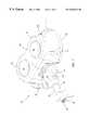
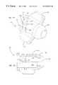
- FIG. 1is a perspective view of a portal assembly according to the present invention including a catheter connector.
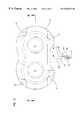
- FIG. 2is a perspective view of the port of FIG. 1 .
- FIG. 3is a top view of the port.
- FIG. 4is a front view of the port.
- FIG. 5is a top view of the port, showing the catheter positioned on the outlet tubes, and the locking sleeve positioned over the catheter ready to connect the catheter to the port.
- FIG. 6is a cross-sectional top view of FIG. 5, taken along lines A—A of FIG. 4 .
- FIG. 7is a top view of the port related to FIG. 5 showing the locking sleeve now in the locked position.
- FIG. 8is a cross-sectional top view of FIG. 7, taken along lines A—A of FIG. 4 .
- FIG. 8Ais an enlarged cross-sectional top view of a portion of the portal assembly of FIG. 8 showing the catheter seal.
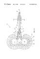
- FIG. 9is an exploded cross-sectional front view of the port before assembly, taken along lines B—B of FIG. 3, without the outlet tubes or the outlet tube support.
- FIG. 10is a bottom perspective view of the base of the reservoir.
- FIG. 11is a cross-sectional top view of the base of the reservoir.
- FIG. 12is a top view of one of the caps of the reservoir.
- FIG. 13is a top view of one of the outlet tubes with a proximal end portion shown in cross-section.
- FIG. 14is a cross-sectional end view of the outlet tube of FIG. 13 taken along lines C—C.
- FIG. 15is a perspective view of the outlet tube support.
- FIG. 16is a cross-sectional side view of the outlet tube support taken along lines D—D of FIG. 15 .
- FIG. 17is a rear end view of the outlet tube support.
- FIG. 18is a front end view of the outlet tube support.
- FIG. 19is a perspective view of the cowl of the outer housing of the port.
- FIG. 20is a perspective view of the base of the outer housing of the port.
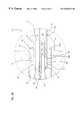
- FIG. 21is a perspective view of the locking sleeve.
- FIG. 22is an end view of the locking sleeve.
- FIG. 23is an opposite end view of the locking sleeve relative to FIG. 22 .
- FIG. 24is a cross-sectional view of the locking sleeve taken along lines E—E of FIG. 23 .
- FIG. 25is a side view of the locking sleeve.
- FIG. 26is an alternative side view to FIG. 25 with the locking sleeve rotated relative to the view of FIG. 25 .
- FIG. 27is a cross-sectional side view of the compression seal.
- FIG. 28is an end view of the dual lumen catheter.
- FIG. 29is a top view of a first alternative locking sleeve.
- FIG. 30is a top view of a second alternative locking sleeve.
- FIG. 31is a top view of a third alternative locking sleeve.
- a catheter connectorincluding a compression fitting for sealing a catheter to a tube of a base arrangement, such as a port.
- the base arrangementincludes a stop surface.
- the connectorincludes a locking member including a stop surface. The two stop surfaces compress a compression seal to seal the catheter to the tube.
- the locking membermounts to the base arrangement with a cam and bayonet system.
- the camis formed on a moveable lever arm which functions as a compensating member.
- the locking memberis preferably a sleeve which holds the compression seal in an internal chamber.
- the compensating memberis provided to allow for consistent sealing of the catheter.
- Other compensating memberswhich can be provided in combination with the lever arm or instead of the lever arm include recesses or holes in the locking sleeve to receive portions of the compression seal, and/or a flexible stop surface within the locking sleeve.
- Another aspect of the present inventionalso relates to a compression fitting where the compression seal which seals the catheter to the tube or tubes has an undulating shape for forming a plurality of ring seals.
- a further aspect of the present inventionalso relates to a compression fitting where the tip of the catheter is received in a generally cylindrical recess of the base arrangement.
- the recessincludes a stop surface for engaging the end of the catheter.
- an inspection holeis provided for visually checking whether the catheter is fully inserted into the recess.
- Preferred base arrangements in accordance with the inventioninclude implantable ports including at least one pierceable septum.
- Preferred base arrangementsalso include two outlet tubes which are sealed to a dual lumen catheter by the compression fitting.
- the preferred outlet tubes and lumens of the dual port and catheterincludes rounded D-shapes with curved corners.
- the present inventionalso relates to methods of use of a catheter connector where the connector includes a compression fitting including a compression seal.
- One aspect of the method of use in accordance with the present inventionrelates to providing a cam slot and bayonet to lock the compression fitting, where the method includes positioning the cam slot on a moveable lever arm, and moving the lever arm during locking of the compression fitting to compensate for overcompression of the seal. Further methods include moving an end portion of the locking sleeve to compensate for overcompression of the seal. Still further methods include flowing the seal into a recess or hole of the locking sleeve for overcompression of the seal.
- Another aspect of the method of use in accordance with the present inventionrelates to forming a plurality of ring seals with the compression seal between the catheter and the outlet tube or tubes of the connector.
- a further aspect of the method of use in accordance with the present inventionrelates to positioning the end of the catheter within the connector in a generally cylindrical recess, the end of the catheter positioned within the recess and over the outlet tube or tubes so as to engage a stop surface.
- the present inventionprovides a connector for connecting a catheter to a base arrangement with at least one outlet tube.
- the base arrangementpreferably includes an access port for implantation under the skin and two side by side outlet tubes.
- the connectorincludes a locking member and a compression seal which cooperates with the base arrangement to radially inwardly compress the catheter to the outlet tube or tubes.
- the preferred compression sealproduces a plurality of ring seals between the catheter and the outlet tube or tubes.
- a cam and bayonet arrangement with an overcenter portionlocks the locking member to the base arrangement and provides consistent sealing of the catheter, as well as a mechanical advantage for the operator, and secure locking.
- the connectorincludes a compensating feature for allowing consistent locking of the locking member to the base arrangement.
- the base arrangementalso receives an end of the catheter for further sealing of the catheter to the base arrangement.
- FIGS. 9 through 28show features of portal assembly 20 in greater detail.
- Portal assembly 20includes a portal or port 22 , a catheter 24 , and a connector 26 connecting catheter 24 to port 22 with a fluid-tight seal.
- Portal assembly 20is implantable under the skin for use in infusing drugs or other fluids to the patient entering at port 22 and exiting at a distal end 25 of catheter 24 .
- Portal assembly 20is also utilized in some situations as a port for withdrawing blood or other fluids from the body via catheter 24 . In either case, catheter 24 has distal end 25 at the desired location within the patient's body.
- Connector 26connects a proximate end 32 of catheter 24 to port 22 . Connector 26 also permits disconnection of catheter 24 from port 22 at the desired time.
- Catheter 24is made from a bio-compatible and flexible, elastic polymeric material, such as silicone or polyurethane.
- port 22is a dual port.
- Two different needle access sites 28are provided with a dual port configuration.
- the dual port configurationincludes two outlet tubes 34 , 36 as shown in FIG. 2 .
- catheter 24is a dual lumen configuration with a first lumen 30 and a second lumen 31 as shown in FIGS. 1, 6 and 28 .
- Distal ends 68 , 70 of outlet tubes 34 , 36extend generally parallel to axis 71 and in close proximity to one another.
- Each lumen 30 , 31 of catheter 24is in fluid communication with one of outlet tubes 34 , 36 . Additional outlet tubes and an appropriately configured catheter 24 can be provided if more than two access sites are provided.
- portal assembly 20can instead be a single port configuration, with a single outlet tube, and catheter 24 can be a single lumen. It is to be appreciated that, for a multi-port configuration, outlet tubes 34 , 36 can be positioned in a spaced apart configuration (not shown). In that case, a connector 26 would be provided for each outlet tube and catheter 24 would be a single lumen.
- Outlet tubes 34 , 36are shown as being made from generally tubular shaped bio-compatible metallic materials, such as titanium. Other materials, such as plastics and other non-metallic materials, in other shapes are possible. Angled shapes (FIG. 13) are provided to link two access sites to a dual lumen catheter. As will be described below, ends 68 , 70 of outlet tubes 34 , 36 are provided with a rounded D-shaped outer surface 69 , such as shown in FIG. 14 . Such shapes generally match the shapes of lumens 30 , 31 of catheter 24 .
- Port 22includes a body 50 and a plurality of suture holes 52 for use in suturing port 22 to the patient.
- Port 22includes two pierceable septums 66 defining the two access sites 28 which close off two internal chambers 65 within body 50 .
- Each chamber 65is in fluid communication with one of outlet tubes 34 , 36 .
- Body 50 of port 22can be made from a variety of materials, including all metal, all plastic, combinations thereof, or other materials which are bio-compatible.
- port 22is a hybrid construction including a metallic reservoir 60 , such as titanium, surrounded by an outer housing 100 made from plastic, such as polysulfone.
- U.S. Pat. No. 5,378,192 to SIMS Deltec of St. Paul, Minn.details various hybrid constructions for ports. The disclosure of U.S. Pat. No. 5,378,192 is hereby incorporated by reference.
- reservoir 60generally includes a base 62 , and two caps 64 each with a central opening 67 .
- Each cap 64is interference fit to base 62 .
- Caps 64hold pierceable septums 66 to define enclosed chambers 65 .
- each septum 66is wafer shaped before caps 64 compress a periphery of each septum 66 which causes the central region to bulge outward as shown in FIG. 1 .
- An exterior surface 72 of each cap 64engages an interior surface 74 of upper chamber 76 of base 62 to form the interference fit.
- Each septum 66is trapped between a lip 78 of cap 64 and a shoulder 79 of base 62 around the periphery of septum 66 .
- Outlet tubes 34 , 36are welded to base 62 adjacent to each chamber 65 .
- Each of chambers 65 of reservoir 60are in fluid communication with outlet tubes 34 , 36 respectively, such as shown in FIG. 8 . Therefore, fluids injected into chambers 65 via a needle which pierces one of septums 66 , is in fluid communication with the respective outlet tubes 34 , 36 for delivery to a site in the patient's body at distal end 25 of catheter 24 .
- Outer housing 100generally includes a base 102 (FIG. 20) and a cowl 104 (FIG. 19) attached to one another around reservoir 60 , such as by ultrasonic welding.
- Cowl 104includes two openings 105 which expose septums 66 when housing 100 is around reservoir 60 .
- Outlet tubes 34 , 36extend from housing 100 between a slot 106 of base 102 and a slot 108 of cowl 104 .
- Bumps 202 on base 102are provided for assembly tolerance compensation. During assembly, bumps 202 engage reservoir 60 and melt down to the appropriate size so as to prevent reservoir 60 from rattling within outer housing 100 .
- Optional ridges 208 on cowl 104(shown only on one side) are provided for extraction of the component from the injection mold.
- a metallic support 80(FIGS. 15-18) which supports outlet tubes 34 , 36 .
- a first end 81 of support 80is received within a recess 63 of base 62 of reservoir 60 .
- Support 80is also received in slots 106 , 108 of housing 100 .
- End 81includes two spaced apart tabs 83 a , 83 b .
- a central section 85defines an oval shaped passage (see FIGS. 6 and 17 ).
- An inner circular shoulder 87closely surrounds and supports outlet tubes 34 , 36 (See FIGS. 8A, 17 and 18 ).
- a locking sleeve 120including an inner compression seal 140 to seal catheter 24 to outlet tubes 34 , 36 , mounts to support 80 to hold catheter 24 in sealing engagement with port 22 .
- Support 80 and locking sleeve 120form a compression fitting to seal catheter 24 to outlet tubes 34 , 36 .
- Seal 140is concentric about a longitudinal axis 141 and defines a generally tubular shape.
- Seal 140is made of resilient material, such as molded silicone. As will be described below, a preferred seal 140 includes an undulating shape. During use, seal 140 is axially compressed resulting in a radially inward acting force applied to catheter 24 to seal catheter 24 to outlet tubes 34 , 36 .
- Support 80extends from reservoir 60 and includes a generally circular distal end 82 .
- Distal end surface 84is generally perpendicular to a longitudinal axis 86 of support 80 .
- Distal end 82 of support 80further includes two bayonets 88 , 90 on opposite sides of end 82 .
- Support 80further includes an inner passage 92 , defining a cylindrically shaped chamber 93 at end 82 and an internal stop surface 94 for receipt of an end 32 a of catheter 24 . Inspection holes 180 are provided to visually inspect whether catheter 24 is positioned in chamber 93 .
- Stop surface 94is generally perpendicular to axis 86 .
- Locking sleeve 120includes a body 121 , such as made from metal (titanium), with a solid end ring 122 .
- An inwardly projecting shoulder 124is disposed at a second end 126 of locking sleeve 120 .
- Inner passage 123receives catheter 24 and seal 140 , with one end 140 a adjacent to shoulder 124 .
- an opposite end 140 b of seal 140is positioned adjacent to end surface 84 of support 80 .
- Locking sleeve 120is axially moved relative to support 80 which results in compression of seal 140 .
- Shoulder 124is generally perpendicular to axis 125 .
- Locking sleeve 120includes two slots 128 , 129 which cooperate with bayonets 88 , 90 of support 80 to mount locking sleeve 120 to support 80 .
- Slots 128 , 129are generally identically shaped on opposite sides of locking sleeve 120 .
- the slotis configured as a cam surface 130 which provides camming action of locking sleeve 120 relative to support 80 for use in providing mechanical advantage to axially compress seal 140 during locking.
- Cam surface 130can be angled as desired to vary the torque required to lock locking sleeve 120 and seal catheter 24 .
- outwardly extending wings or lever arms 132are provided extending from a central portion of lock ring 120 .
- Recess 134 of port 22is configured to fairly closely receive wings 132 of locking sleeve 120 as shown in FIG. 7 .
- Locking sleeve 120is shown as being turned in a clockwise direction to seal catheter 24 against outlet tubes 34 , 36 . A counterclockwise arrangement is also possible (not shown).
- Slot 128includes an overcenter surface or detent 160 which locates bayonet 88 to hold locking sleeve 120 in the locked position as best shown in FIGS. 1, 7 , 8 and 8 A.
- An axial forceis exerted on locking sleeve 120 by seal 140 in a direction away from support 80 .
- bayonet 88cannot work its way past detent 160 and along cam surface 130 to possibly inadvertently allow catheter 24 to become separated from port 22 .
- detent 160will not allow an errant needle to unlock locking sleeve 120 . Further, the surgeon will realize instantly that connector 26 is properly locked when bayonet 88 reaches detent 160 during connection of catheter 24 to port 22 .
- a similar detentis provided for the other bayonet 90 .
- Cam surface 130is formed on a moveable lever arm 170 of locking sleeve 120 so as to provide flexibility in locking sleeve 120 , to assure consistent sealing.
- Lever arm 170 in the preferred embodimentis formed by continuing slot 128 at 128 a so as to form cam surface 130 on a projecting arm.
- the size and shape of connecting region 172controls the amount of flexing allowed in arm 170 .
- Arm 170flexes in the direction of arrow A to assure that bayonets 88 , 90 lock into detents 160 . This is useful as a compensating mechanism to lessen the emphasis on the components of locking sleeve 120 having precise tolerances.
- lever arm 170With lever arm 170 , a fluid tight seal is achieved over a larger range of relative sizes of body 121 and seal 140 of locking sleeve 120 . Without lever arm 170 , undue force may be required to reach detents 160 due to overcompression of the seal. Lever arm 170 is particularly useful in preferred connector 26 which locks through a relatively short amount of rotation (approximately 90°). Slot 128 a is sized to accommodate the total range of tolerances in the components of the locking sleeve 120 .
- FIG. 29shows a first alternative locking sleeve 120 a with internal recesses or grooves 122 a in body 121 a for receipt of seal 140 so as to compensate for overcompression of seal 140 .
- FIG. 30shows a second alternative locking sleeve 120 b with holes 124 b through body 121 b so as to compensate for overcompression of seal 140 .
- FIG. 31shows a third alternative locking sleeve 120 c with a flexible second end 126 c .
- Second end 126 cincludes slots 128 c formed in end 126 c which provides flexibility in end 126 c . This flexibility permits compensation for overcompression of seal 140 .
- body 121can be provided with a spring member or an elastomer which biases cam surface 130 toward end 126 so asto allow compensation of overcompression of seal 140 .
- compression seal 140 in the preferred embodimentincludes an undulating shape along an inner diameter portion 142 , and also along an outer diameter portion 144 .
- the undulating shapeincludes plurality of alternating rings 148 and recesses 146 . Once seal 140 is compressed axially, a plurality of ring seals are formed between catheter 24 and outlet tubes 34 , 36 from the inward expansion of rings 148 . While the undulating shape of compression seal 140 is preferred, other shapes are possible, including generally cylindrical.
- the undulating shape for seal 140is preferred since it exerts a force in a 360° manner in a plurality of locations on catheter 24 .
- the use of recesses 146further assists in compensating for variations in relative sizes of the system components, while still assuring a sufficient seal is formed.
- Rings 148further assist to resist pullout by catheter 24 due to the concentration of the radial forces on catheter 24 at each ring 148 .
- the use of concentric rings 148further provides more predictability over a cylindrical seal for the inward radial expansion of seal 140 so that a sufficient seal is formed. For example, seal 140 is less likely to produce unsymmetrical buckling than a cylindrical seal.
- Rings 148are generally circular in cross-section. It is to be appreciated that other shapes are possible with sharper or smoother curves or angles to change the nature of the ring seals on catheter 24 . Also, recesses 146 can be deeper or shallower to control the compression of seal 140 . Non-uniform shapes along axis 141 are possible.
- Cylindrical chamber 93 within support 80generally constrains end 32 a of catheter 24 during sealing.
- the receipt of end 32 a in chamber 93helps to seal catheter 24 .
- catheter end 32 amay flow toward stop surface 94 , leading to further compression, and sealing, of catheter 24 at end 32 a against stop surface 94 .
- septum 32 b of catheter 32is compressed, and further sealed, by the slight movement of outlet tubes 32 , 34 toward one another from the resulting effect of radial compression by seal 140 on catheter 24 .
- Connector 26generally includes the two outlet tubes 34 , 36 , the distal end of 82 of support 80 , and locking sleeve 120 . Together, outlet tubes 34 , 36 , and distal end 82 of support 80 form a base arrangement portion of connector 26 .
- Connector 26is useable not only in portal assembly 20 but in other structures where it is desired to securably connect a device to a catheter.
- a preferred use of connector 26 with catheter 24 and port 22positions by hand the end 32 of catheter 24 over the ends 68 , 70 of outlet tubes 34 , 36 , and end 32 a within chamber 93 of end 82 of support 80 and engaged with stop surface 94 . Verification that catheter 24 is properly positioned within support 80 is through inspection hole 180 (see FIG. 5 ). As locking sleeve 120 is rotated to mount to support 80 through bayonets 88 , 90 , compression seal 140 is compressed axially, which results in a radial compression on catheter 24 against outlet tubes 34 , 36 to form a plurality of ring seals.
- Detents 160hold bayonets 88 , 90 and locking sleeve 120 in the locked state until it is desired to disconnect catheter 24 from port 22 .
- Arm 170pivots as needed to allow bayonets 88 , 90 to reach detents 160 for locking.
- connector 26in the case of the dual outlet tube configuration, achieves its seal by seal 140 engaging catheter 24 to seal catheter 24 against outlet tubes 34 , 36 , and also end 32 a pushed into stop surface 94 as seal 140 compresses catheter 24 . Also the squeezing together of outlet tubes 34 , 36 is believed to cause sealing of septum 32 b of catheter 24 against tubes 34 , 36 .
- both outlet tubes 34 , 36 and lumens 30 , 31 of catheter 24include D-shapes.
- Such D-shapes on tubes 34 , 36include rounded corners 180 .
- the D-shaped lumens 30 , 31include rounded corners 182 .
- the rounded corners of the D-shapesfacilitate a fluid tight seal from the compression-style fitting around a dual lumen catheter.
- the back-to-back D-shapesallow relatively high fluid flow in a catheter having a circular outer cross-section.
- D-shapesbe related as follows:
- the Interferenceis the overall interference of the catheter internal lumen with the outlet tube outside surface.
- the catheter lumen inside surfaceneeds to contact the outside surface of the outlet tube throughout the fall perimeter. Gaps may form with sharper corners when a compression-type fitting is used. When rounded corners are provided as shown in the drawings and described above, gaps are sufficiently reduced or eliminated.
Landscapes
- Health & Medical Sciences (AREA)
- Heart & Thoracic Surgery (AREA)
- Pulmonology (AREA)
- Engineering & Computer Science (AREA)
- Anesthesiology (AREA)
- Biomedical Technology (AREA)
- Hematology (AREA)
- Life Sciences & Earth Sciences (AREA)
- Animal Behavior & Ethology (AREA)
- General Health & Medical Sciences (AREA)
- Public Health (AREA)
- Veterinary Medicine (AREA)
- Infusion, Injection, And Reservoir Apparatuses (AREA)
Abstract
Description
Claims (11)
Priority Applications (1)
| Application Number | Priority Date | Filing Date | Title |
|---|---|---|---|
| US09/673,709US6562023B1 (en) | 1999-04-23 | 1999-04-23 | Catheter connector including seal ring and method |
Applications Claiming Priority (2)
| Application Number | Priority Date | Filing Date | Title |
|---|---|---|---|
| PCT/US1999/008507WO1999053981A1 (en) | 1998-04-23 | 1999-04-23 | Catheter connector including seal ring and method |
| US09/673,709US6562023B1 (en) | 1999-04-23 | 1999-04-23 | Catheter connector including seal ring and method |
Publications (1)
| Publication Number | Publication Date |
|---|---|
| US6562023B1true US6562023B1 (en) | 2003-05-13 |
Family
ID=24703794
Family Applications (1)
| Application Number | Title | Priority Date | Filing Date |
|---|---|---|---|
| US09/673,709Expired - LifetimeUS6562023B1 (en) | 1999-04-23 | 1999-04-23 | Catheter connector including seal ring and method |
Country Status (1)
| Country | Link |
|---|---|
| US (1) | US6562023B1 (en) |
Cited By (65)
| Publication number | Priority date | Publication date | Assignee | Title |
|---|---|---|---|---|
| US20030083678A1 (en)* | 2001-10-26 | 2003-05-01 | Atrium Medical Corporation | Body fluid cartridge exchange platform device |
| US20040002693A1 (en)* | 2002-06-26 | 2004-01-01 | Bright Jeffrey D. | Implantable pump connector for catheter attachment |
| US20050253389A1 (en)* | 2004-05-13 | 2005-11-17 | Schulte Gregory T | Medical tubing connector assembly incorporating strain relief sleeve |
| US20050261636A1 (en)* | 2004-03-18 | 2005-11-24 | Rome Guy T | Valved catheter |
| US20060184142A1 (en)* | 2005-01-21 | 2006-08-17 | Medical Components, Inc. | Catheter infusion port |
| US20060200201A1 (en)* | 2005-02-16 | 2006-09-07 | Transoma Medical, Inc. | Implantable housing with catheter strain relief |
| US20060264911A1 (en)* | 2005-05-20 | 2006-11-23 | Medtronic, Inc. | Squeeze-actuated catheter connector and method |
| US20060264814A1 (en)* | 2005-05-20 | 2006-11-23 | Medtronic, Inc. | Locking catheter connector and method |
| US20070010796A1 (en)* | 2005-06-23 | 2007-01-11 | Derek Moran | Catheter device |
| FR2893255A1 (en)* | 2005-11-16 | 2007-05-18 | Cie Euro Etude Rech Paroscopie | ATRAUMATIC IMPLANTABLE MEDICAL SITE OF SIMPLIFIED CONSTRUCTION |
| US20070276344A1 (en)* | 2006-05-22 | 2007-11-29 | Medical Components, Inc. | Septum for venous access port assembly |
| US20080007045A1 (en)* | 2004-12-13 | 2008-01-10 | Steppe Dennis L | Tubing fitting |
| US20080114308A1 (en)* | 2006-11-13 | 2008-05-15 | Di Palma Giorgio | Vascular Access Port with Catheter Connector |
| US20080215035A1 (en)* | 2006-12-22 | 2008-09-04 | Medingo, Ltd. | Systems, devices and methods for sustained delivery of a therapeutic fluid |
| USD578203S1 (en)* | 2007-06-19 | 2008-10-07 | Medical Components, Inc. | Dual chamber venous access port |
| US20080319405A1 (en)* | 2007-06-22 | 2008-12-25 | Medical Components, Inc. | Low Profile Venous Access Port Assembly |
| US7537245B2 (en) | 2005-02-14 | 2009-05-26 | Medtronic, Inc. | Strain relief device and connector assemblies incorporating same |
| US20090221976A1 (en)* | 2008-02-29 | 2009-09-03 | Medical Components, Inc | Venous Access Port Assembly with Push Surfaces |
| US20090227951A1 (en)* | 2005-04-27 | 2009-09-10 | C. R. Bard, Inc | Assemblies for identifying a power injectable access port |
| US20100010445A1 (en)* | 2004-03-18 | 2010-01-14 | C. R. Bard, Inc. | Connector system for a proximally trimmable catheter |
| USD613394S1 (en) | 2008-02-29 | 2010-04-06 | Medical Components, Inc. | Venous access port assembly |
| USD619242S1 (en) | 2008-05-27 | 2010-07-06 | Medical Components, Inc. | Venous access port assembly |
| US7875019B2 (en) | 2005-06-20 | 2011-01-25 | C. R. Bard, Inc. | Connection system for multi-lumen catheter |
| US20110098663A1 (en)* | 2009-10-27 | 2011-04-28 | Medical Components, Inc. | Implantable port with a pivotably coupled stem |
| US8016789B2 (en) | 2008-10-10 | 2011-09-13 | Deka Products Limited Partnership | Pump assembly with a removable cover assembly |
| US8034026B2 (en) | 2001-05-18 | 2011-10-11 | Deka Products Limited Partnership | Infusion pump assembly |
| US8066672B2 (en) | 2008-10-10 | 2011-11-29 | Deka Products Limited Partnership | Infusion pump assembly with a backup power supply |
| US8083728B2 (en) | 2004-03-18 | 2011-12-27 | C. R. Bard, Inc. | Multifunction adaptor for an open-ended catheter |
| US8177771B2 (en) | 2004-03-18 | 2012-05-15 | C. R. Bard, Inc. | Catheter connector |
| US8177770B2 (en) | 2004-04-01 | 2012-05-15 | C. R. Bard, Inc. | Catheter connector system |
| US8223028B2 (en) | 2008-10-10 | 2012-07-17 | Deka Products Limited Partnership | Occlusion detection system and method |
| US8262616B2 (en) | 2008-10-10 | 2012-09-11 | Deka Products Limited Partnership | Infusion pump assembly |
| US8267892B2 (en) | 2008-10-10 | 2012-09-18 | Deka Products Limited Partnership | Multi-language / multi-processor infusion pump assembly |
| US8337484B2 (en) | 2009-06-26 | 2012-12-25 | C. R. Band, Inc. | Proximally trimmable catheter including pre-attached bifurcation and related methods |
| USD676955S1 (en) | 2010-12-30 | 2013-02-26 | C. R. Bard, Inc. | Implantable access port |
| US8382723B2 (en) | 2005-03-04 | 2013-02-26 | C. R. Bard, Inc. | Access port identification systems and methods |
| US8382724B2 (en) | 2005-03-04 | 2013-02-26 | C. R. Bard, Inc. | Systems and methods for radiographically identifying an access port |
| USD682416S1 (en) | 2010-12-30 | 2013-05-14 | C. R. Bard, Inc. | Implantable access port |
| US8608713B2 (en) | 1998-12-07 | 2013-12-17 | C. R. Bard, Inc. | Septum feature for identification of an access port |
| US8641676B2 (en) | 2005-04-27 | 2014-02-04 | C. R. Bard, Inc. | Infusion apparatuses and methods of use |
| US8708376B2 (en) | 2008-10-10 | 2014-04-29 | Deka Products Limited Partnership | Medium connector |
| US8777931B2 (en) | 2011-08-19 | 2014-07-15 | Alcon Research, Ltd. | Retractable luer lock fittings |
| US20140243789A1 (en)* | 2013-02-27 | 2014-08-28 | Neerav Mehta | Subcutaneous Dialysis Catheter with Ultrasound Agitation |
| US8932271B2 (en) | 2008-11-13 | 2015-01-13 | C. R. Bard, Inc. | Implantable medical devices including septum-based indicators |
| US9079004B2 (en) | 2009-11-17 | 2015-07-14 | C. R. Bard, Inc. | Overmolded access port including anchoring and identification features |
| US9173996B2 (en) | 2001-05-18 | 2015-11-03 | Deka Products Limited Partnership | Infusion set for a fluid pump |
| US9180245B2 (en) | 2008-10-10 | 2015-11-10 | Deka Products Limited Partnership | System and method for administering an infusible fluid |
| US9265912B2 (en) | 2006-11-08 | 2016-02-23 | C. R. Bard, Inc. | Indicia informative of characteristics of insertable medical devices |
| US9474888B2 (en) | 2005-03-04 | 2016-10-25 | C. R. Bard, Inc. | Implantable access port including a sandwiched radiopaque insert |
| US9579496B2 (en) | 2007-11-07 | 2017-02-28 | C. R. Bard, Inc. | Radiopaque and septum-based indicators for a multi-lumen implantable port |
| US9603993B2 (en) | 2005-03-04 | 2017-03-28 | C. R. Bard, Inc. | Access port identification systems and methods |
| US9642986B2 (en) | 2006-11-08 | 2017-05-09 | C. R. Bard, Inc. | Resource information key for an insertable medical device |
| US10307581B2 (en) | 2005-04-27 | 2019-06-04 | C. R. Bard, Inc. | Reinforced septum for an implantable medical device |
| US10688242B2 (en)* | 2012-03-28 | 2020-06-23 | Angiodynamics, Inc. | High flow rate dual reservoir port system |
| USD890334S1 (en)* | 2018-04-04 | 2020-07-14 | Marius Saines | Low profile self-sealing access port |
| US11096582B2 (en) | 2018-11-20 | 2021-08-24 | Veris Health Inc. | Vascular access devices, systems, and methods for monitoring patient health |
| US20220016404A1 (en)* | 2020-07-20 | 2022-01-20 | Cerebral Therapeutics, Inc. | Fluid catheter device for recording brain state |
| US11471647B2 (en) | 2014-11-07 | 2022-10-18 | C. R. Bard, Inc. | Connection system for tunneled catheters |
| US20230011575A1 (en)* | 2021-07-08 | 2023-01-12 | Incube Labs, Llc | Implantable drug delivery systems, assemblies, and methods |
| US11766550B2 (en) | 2017-05-21 | 2023-09-26 | Veris Health, Inc. | Implantable medication infusion port with physiologic monitoring |
| US11890443B2 (en) | 2008-11-13 | 2024-02-06 | C. R. Bard, Inc. | Implantable medical devices including septum-based indicators |
| US11896782B2 (en) | 2017-08-23 | 2024-02-13 | C. R. Bard, Inc. | Priming and tunneling system for a retrograde catheter assembly |
| US12186531B2 (en) | 2008-10-10 | 2025-01-07 | Deka Products Limited Partnership | Infusion pump assembly |
| US12239811B2 (en) | 2018-11-20 | 2025-03-04 | Veris Health Inc. | Wireless charging, localization, and data communication for implantable vascular access devices |
| US12370327B2 (en) | 2008-10-10 | 2025-07-29 | Deka Products Limited Partnership | Infusion pump methods, systems and apparatus |
Citations (8)
| Publication number | Priority date | Publication date | Assignee | Title |
|---|---|---|---|---|
| US5127626A (en)* | 1989-10-31 | 1992-07-07 | Applied Vascular Devices, Inc. | Apparatus for sealing around members extending therethrough |
| US5147305A (en)* | 1989-04-03 | 1992-09-15 | Olympus Optical Co., Ltd. | Medical instrument and valve to be mounted on a mount piece of that instrument |
| US5171216A (en)* | 1989-08-28 | 1992-12-15 | Thermedics, Inc. | Multi-lumen catheter coupling |
| US5185003A (en) | 1989-04-11 | 1993-02-09 | B. Braun Melsungen Ag | Port for injecting medicaments |
| US5279597A (en)* | 1992-01-13 | 1994-01-18 | Arrow International Investment Corp. | Catheter compression clamp |
| US5558641A (en) | 1994-01-24 | 1996-09-24 | Sims Deltec, Inc. | Hybrid portal and method |
| US5562618A (en)* | 1994-01-21 | 1996-10-08 | Sims Deltec, Inc. | Portal assembly and catheter connector |
| US6019748A (en)* | 1995-12-15 | 2000-02-01 | Icu Medical, Inc. | Medical valve with fluid escape space |
- 1999
- 1999-04-23USUS09/673,709patent/US6562023B1/ennot_activeExpired - Lifetime
Patent Citations (8)
| Publication number | Priority date | Publication date | Assignee | Title |
|---|---|---|---|---|
| US5147305A (en)* | 1989-04-03 | 1992-09-15 | Olympus Optical Co., Ltd. | Medical instrument and valve to be mounted on a mount piece of that instrument |
| US5185003A (en) | 1989-04-11 | 1993-02-09 | B. Braun Melsungen Ag | Port for injecting medicaments |
| US5171216A (en)* | 1989-08-28 | 1992-12-15 | Thermedics, Inc. | Multi-lumen catheter coupling |
| US5127626A (en)* | 1989-10-31 | 1992-07-07 | Applied Vascular Devices, Inc. | Apparatus for sealing around members extending therethrough |
| US5279597A (en)* | 1992-01-13 | 1994-01-18 | Arrow International Investment Corp. | Catheter compression clamp |
| US5562618A (en)* | 1994-01-21 | 1996-10-08 | Sims Deltec, Inc. | Portal assembly and catheter connector |
| US5558641A (en) | 1994-01-24 | 1996-09-24 | Sims Deltec, Inc. | Hybrid portal and method |
| US6019748A (en)* | 1995-12-15 | 2000-02-01 | Icu Medical, Inc. | Medical valve with fluid escape space |
Cited By (131)
| Publication number | Priority date | Publication date | Assignee | Title |
|---|---|---|---|---|
| US8608713B2 (en) | 1998-12-07 | 2013-12-17 | C. R. Bard, Inc. | Septum feature for identification of an access port |
| US8034026B2 (en) | 2001-05-18 | 2011-10-11 | Deka Products Limited Partnership | Infusion pump assembly |
| US9173996B2 (en) | 2001-05-18 | 2015-11-03 | Deka Products Limited Partnership | Infusion set for a fluid pump |
| US20030083678A1 (en)* | 2001-10-26 | 2003-05-01 | Atrium Medical Corporation | Body fluid cartridge exchange platform device |
| US6981977B2 (en) | 2001-10-26 | 2006-01-03 | Atrium Medical Corporation | Body fluid cartridge exchange platform device |
| US20040002693A1 (en)* | 2002-06-26 | 2004-01-01 | Bright Jeffrey D. | Implantable pump connector for catheter attachment |
| US20050096635A1 (en)* | 2002-06-26 | 2005-05-05 | Bright Jeffrey D. | Implantable pump connector for catheter attachment |
| US7452354B2 (en) | 2002-06-26 | 2008-11-18 | Inset Technologies Incorporated | Implantable pump connector for catheter attachment |
| US7927325B2 (en) | 2002-06-26 | 2011-04-19 | Medasys Incorporated | Implantable pump connector for catheter attachment |
| US20050242579A1 (en)* | 2002-06-26 | 2005-11-03 | Bright Jeffrey D | Connector for catheter attachment to an implantable pump |
| US7883502B2 (en) | 2004-03-18 | 2011-02-08 | C. R. Bard, Inc. | Connector system for a proximally trimmable catheter |
| US7854731B2 (en)* | 2004-03-18 | 2010-12-21 | C. R. Bard, Inc. | Valved catheter |
| US20100010445A1 (en)* | 2004-03-18 | 2010-01-14 | C. R. Bard, Inc. | Connector system for a proximally trimmable catheter |
| US8523840B2 (en) | 2004-03-18 | 2013-09-03 | C. R. Bard, Inc. | Connector system for a proximally trimmable catheter |
| US8083728B2 (en) | 2004-03-18 | 2011-12-27 | C. R. Bard, Inc. | Multifunction adaptor for an open-ended catheter |
| US20050261636A1 (en)* | 2004-03-18 | 2005-11-24 | Rome Guy T | Valved catheter |
| US8177771B2 (en) | 2004-03-18 | 2012-05-15 | C. R. Bard, Inc. | Catheter connector |
| US8177770B2 (en) | 2004-04-01 | 2012-05-15 | C. R. Bard, Inc. | Catheter connector system |
| US7331613B2 (en) | 2004-05-13 | 2008-02-19 | Medtronic, Inc. | Medical tubing connector assembly incorporating strain relief sleeve |
| US20080103476A1 (en)* | 2004-05-13 | 2008-05-01 | Medtronic, Inc. | Medical tubing connector assembly incorporating strain relief sleeve |
| US20050253389A1 (en)* | 2004-05-13 | 2005-11-17 | Schulte Gregory T | Medical tubing connector assembly incorporating strain relief sleeve |
| US20080007045A1 (en)* | 2004-12-13 | 2008-01-10 | Steppe Dennis L | Tubing fitting |
| US7523967B2 (en)* | 2004-12-13 | 2009-04-28 | Alcon, Inc. | Tubing fitting |
| US20060184142A1 (en)* | 2005-01-21 | 2006-08-17 | Medical Components, Inc. | Catheter infusion port |
| US7850666B2 (en) | 2005-01-21 | 2010-12-14 | Medical Components, Inc. | Catheter infusion port |
| US7537245B2 (en) | 2005-02-14 | 2009-05-26 | Medtronic, Inc. | Strain relief device and connector assemblies incorporating same |
| US20060200201A1 (en)* | 2005-02-16 | 2006-09-07 | Transoma Medical, Inc. | Implantable housing with catheter strain relief |
| US8382724B2 (en) | 2005-03-04 | 2013-02-26 | C. R. Bard, Inc. | Systems and methods for radiographically identifying an access port |
| US8603052B2 (en) | 2005-03-04 | 2013-12-10 | C. R. Bard, Inc. | Access port identification systems and methods |
| US10675401B2 (en) | 2005-03-04 | 2020-06-09 | Bard Peripheral Vascular, Inc. | Access port identification systems and methods |
| US8939947B2 (en) | 2005-03-04 | 2015-01-27 | C. R. Bard, Inc. | Systems and methods for radiographically identifying an access port |
| US9474888B2 (en) | 2005-03-04 | 2016-10-25 | C. R. Bard, Inc. | Implantable access port including a sandwiched radiopaque insert |
| US9603993B2 (en) | 2005-03-04 | 2017-03-28 | C. R. Bard, Inc. | Access port identification systems and methods |
| US9603992B2 (en) | 2005-03-04 | 2017-03-28 | C. R. Bard, Inc. | Access port identification systems and methods |
| US9682186B2 (en) | 2005-03-04 | 2017-06-20 | C. R. Bard, Inc. | Access port identification systems and methods |
| US8585663B2 (en) | 2005-03-04 | 2013-11-19 | C. R. Bard, Inc. | Access port identification systems and methods |
| US10857340B2 (en) | 2005-03-04 | 2020-12-08 | Bard Peripheral Vascular, Inc. | Systems and methods for radiographically identifying an access port |
| US8382723B2 (en) | 2005-03-04 | 2013-02-26 | C. R. Bard, Inc. | Access port identification systems and methods |
| US10905868B2 (en) | 2005-03-04 | 2021-02-02 | Bard Peripheral Vascular, Inc. | Systems and methods for radiographically identifying an access port |
| US10179230B2 (en) | 2005-03-04 | 2019-01-15 | Bard Peripheral Vascular, Inc. | Systems and methods for radiographically identifying an access port |
| US11077291B2 (en) | 2005-03-04 | 2021-08-03 | Bard Peripheral Vascular, Inc. | Implantable access port including a sandwiched radiopaque insert |
| US10238850B2 (en) | 2005-03-04 | 2019-03-26 | Bard Peripheral Vascular, Inc. | Systems and methods for radiographically identifying an access port |
| US10265512B2 (en) | 2005-03-04 | 2019-04-23 | Bard Peripheral Vascular, Inc. | Implantable access port including a sandwiched radiopaque insert |
| US8641676B2 (en) | 2005-04-27 | 2014-02-04 | C. R. Bard, Inc. | Infusion apparatuses and methods of use |
| US10016585B2 (en) | 2005-04-27 | 2018-07-10 | Bard Peripheral Vascular, Inc. | Assemblies for identifying a power injectable access port |
| US10625065B2 (en) | 2005-04-27 | 2020-04-21 | Bard Peripheral Vascular, Inc. | Assemblies for identifying a power injectable access port |
| US8545460B2 (en) | 2005-04-27 | 2013-10-01 | C. R. Bard, Inc. | Infusion apparatuses and related methods |
| US9421352B2 (en) | 2005-04-27 | 2016-08-23 | C. R. Bard, Inc. | Infusion apparatuses and methods of use |
| US10661068B2 (en) | 2005-04-27 | 2020-05-26 | Bard Peripheral Vascular, Inc. | Assemblies for identifying a power injectable access port |
| US10183157B2 (en) | 2005-04-27 | 2019-01-22 | Bard Peripheral Vascular, Inc. | Assemblies for identifying a power injectable access port |
| US8475417B2 (en) | 2005-04-27 | 2013-07-02 | C. R. Bard, Inc. | Assemblies for identifying a power injectable access port |
| US10307581B2 (en) | 2005-04-27 | 2019-06-04 | C. R. Bard, Inc. | Reinforced septum for an implantable medical device |
| US20090227951A1 (en)* | 2005-04-27 | 2009-09-10 | C. R. Bard, Inc | Assemblies for identifying a power injectable access port |
| US10052470B2 (en) | 2005-04-27 | 2018-08-21 | Bard Peripheral Vascular, Inc. | Assemblies for identifying a power injectable access port |
| US8641688B2 (en) | 2005-04-27 | 2014-02-04 | C. R. Bard, Inc. | Assemblies for identifying a power injectable access port |
| US10780257B2 (en) | 2005-04-27 | 2020-09-22 | Bard Peripheral Vascular, Inc. | Assemblies for identifying a power injectable access port |
| US9937337B2 (en) | 2005-04-27 | 2018-04-10 | C. R. Bard, Inc. | Assemblies for identifying a power injectable access port |
| US7387624B2 (en) | 2005-05-20 | 2008-06-17 | Medtronic, Inc. | Squeeze-actuated catheter connecter and method |
| US20060264814A1 (en)* | 2005-05-20 | 2006-11-23 | Medtronic, Inc. | Locking catheter connector and method |
| US7678101B2 (en) | 2005-05-20 | 2010-03-16 | Medtronic, Inc. | Locking catheter connector and connection system |
| US20060264911A1 (en)* | 2005-05-20 | 2006-11-23 | Medtronic, Inc. | Squeeze-actuated catheter connector and method |
| US20110098679A1 (en)* | 2005-06-20 | 2011-04-28 | C. R. Bard, Inc. | Connection system for multi-lumen catheter |
| US7875019B2 (en) | 2005-06-20 | 2011-01-25 | C. R. Bard, Inc. | Connection system for multi-lumen catheter |
| US8617138B2 (en) | 2005-06-20 | 2013-12-31 | C. R. Bard, Inc. | Connection system for multi-lumen catheter |
| US8206376B2 (en)* | 2005-06-20 | 2012-06-26 | C. R. Bard, Inc. | Connection system for multi-lumen catheter |
| US8852168B2 (en) | 2005-06-20 | 2014-10-07 | C. R. Bard, Inc. | Connection system for multi-lumen catheter |
| US20070010796A1 (en)* | 2005-06-23 | 2007-01-11 | Derek Moran | Catheter device |
| US7914519B2 (en) | 2005-06-23 | 2011-03-29 | Elcam Medical Agricultural Cooperative Association, Ltd. | Catheter device |
| DE102006027398B4 (en) | 2005-06-23 | 2020-04-23 | Elcam Medical Agricultural Cooperative Association Ltd. | catheter |
| FR2893255A1 (en)* | 2005-11-16 | 2007-05-18 | Cie Euro Etude Rech Paroscopie | ATRAUMATIC IMPLANTABLE MEDICAL SITE OF SIMPLIFIED CONSTRUCTION |
| US20090221974A1 (en)* | 2005-11-16 | 2009-09-03 | Pascal Paganon | Implantable atraumatic medical site having a simplified design |
| WO2007057567A1 (en)* | 2005-11-16 | 2007-05-24 | Compagnie Europeenne D'etude Et De Recherche De Dispositifs Pour L'implantation Par Laparoscopie | Implantable atraumatic medical site having a simplified design |
| US8608712B2 (en) | 2006-05-22 | 2013-12-17 | Medical Components, Inc. | Septum for venous access port assembly |
| US20070276344A1 (en)* | 2006-05-22 | 2007-11-29 | Medical Components, Inc. | Septum for venous access port assembly |
| US10092725B2 (en) | 2006-11-08 | 2018-10-09 | C. R. Bard, Inc. | Resource information key for an insertable medical device |
| US9642986B2 (en) | 2006-11-08 | 2017-05-09 | C. R. Bard, Inc. | Resource information key for an insertable medical device |
| US10556090B2 (en) | 2006-11-08 | 2020-02-11 | C. R. Bard, Inc. | Resource information key for an insertable medical device |
| US9265912B2 (en) | 2006-11-08 | 2016-02-23 | C. R. Bard, Inc. | Indicia informative of characteristics of insertable medical devices |
| US20080114308A1 (en)* | 2006-11-13 | 2008-05-15 | Di Palma Giorgio | Vascular Access Port with Catheter Connector |
| US20080215035A1 (en)* | 2006-12-22 | 2008-09-04 | Medingo, Ltd. | Systems, devices and methods for sustained delivery of a therapeutic fluid |
| US9662440B2 (en)* | 2006-12-22 | 2017-05-30 | Roche Diabetes Care, Inc. | Systems, devices and methods for sustained delivery of a therapeutic fluid |
| USD578203S1 (en)* | 2007-06-19 | 2008-10-07 | Medical Components, Inc. | Dual chamber venous access port |
| US20080319405A1 (en)* | 2007-06-22 | 2008-12-25 | Medical Components, Inc. | Low Profile Venous Access Port Assembly |
| US9504815B2 (en) | 2007-06-22 | 2016-11-29 | Medical Components, Inc. | Low profile venous access port assembly |
| US9579496B2 (en) | 2007-11-07 | 2017-02-28 | C. R. Bard, Inc. | Radiopaque and septum-based indicators for a multi-lumen implantable port |
| US10086186B2 (en) | 2007-11-07 | 2018-10-02 | C. R. Bard, Inc. | Radiopaque and septum-based indicators for a multi-lumen implantable port |
| US10792485B2 (en) | 2007-11-07 | 2020-10-06 | C. R. Bard, Inc. | Radiopaque and septum-based indicators for a multi-lumen implantable port |
| US11638810B2 (en) | 2007-11-07 | 2023-05-02 | C. R. Bard, Inc. | Radiopaque and septum-based indicators for a multi-lumen implantable port |
| US20090221976A1 (en)* | 2008-02-29 | 2009-09-03 | Medical Components, Inc | Venous Access Port Assembly with Push Surfaces |
| USD613394S1 (en) | 2008-02-29 | 2010-04-06 | Medical Components, Inc. | Venous access port assembly |
| US9561358B2 (en) | 2008-02-29 | 2017-02-07 | Medical Components, Inc. | Venous access port assembly with push surfaces |
| USD619242S1 (en) | 2008-05-27 | 2010-07-06 | Medical Components, Inc. | Venous access port assembly |
| US8262616B2 (en) | 2008-10-10 | 2012-09-11 | Deka Products Limited Partnership | Infusion pump assembly |
| US12370327B2 (en) | 2008-10-10 | 2025-07-29 | Deka Products Limited Partnership | Infusion pump methods, systems and apparatus |
| US12186531B2 (en) | 2008-10-10 | 2025-01-07 | Deka Products Limited Partnership | Infusion pump assembly |
| US8267892B2 (en) | 2008-10-10 | 2012-09-18 | Deka Products Limited Partnership | Multi-language / multi-processor infusion pump assembly |
| US9180245B2 (en) | 2008-10-10 | 2015-11-10 | Deka Products Limited Partnership | System and method for administering an infusible fluid |
| US8708376B2 (en) | 2008-10-10 | 2014-04-29 | Deka Products Limited Partnership | Medium connector |
| US8223028B2 (en) | 2008-10-10 | 2012-07-17 | Deka Products Limited Partnership | Occlusion detection system and method |
| US8066672B2 (en) | 2008-10-10 | 2011-11-29 | Deka Products Limited Partnership | Infusion pump assembly with a backup power supply |
| US8016789B2 (en) | 2008-10-10 | 2011-09-13 | Deka Products Limited Partnership | Pump assembly with a removable cover assembly |
| US10773066B2 (en) | 2008-11-13 | 2020-09-15 | C. R. Bard, Inc. | Implantable medical devices including septum-based indicators |
| US8932271B2 (en) | 2008-11-13 | 2015-01-13 | C. R. Bard, Inc. | Implantable medical devices including septum-based indicators |
| US10052471B2 (en) | 2008-11-13 | 2018-08-21 | C. R. Bard, Inc. | Implantable medical devices including septum-based indicators |
| US11890443B2 (en) | 2008-11-13 | 2024-02-06 | C. R. Bard, Inc. | Implantable medical devices including septum-based indicators |
| US8337484B2 (en) | 2009-06-26 | 2012-12-25 | C. R. Band, Inc. | Proximally trimmable catheter including pre-attached bifurcation and related methods |
| WO2011056619A1 (en)* | 2009-10-27 | 2011-05-12 | Medical Components, Inc. | Implantable port with a pivotably coupled stem |
| US8622980B2 (en)* | 2009-10-27 | 2014-01-07 | Medical Components, Inc. | Implantable port with a pivotably coupled stem |
| US20110098663A1 (en)* | 2009-10-27 | 2011-04-28 | Medical Components, Inc. | Implantable port with a pivotably coupled stem |
| US9717895B2 (en) | 2009-11-17 | 2017-08-01 | C. R. Bard, Inc. | Overmolded access port including anchoring and identification features |
| US9079004B2 (en) | 2009-11-17 | 2015-07-14 | C. R. Bard, Inc. | Overmolded access port including anchoring and identification features |
| US9248268B2 (en) | 2009-11-17 | 2016-02-02 | C. R. Bard, Inc. | Overmolded access port including anchoring and identification features |
| US10155101B2 (en) | 2009-11-17 | 2018-12-18 | Bard Peripheral Vascular, Inc. | Overmolded access port including anchoring and identification features |
| US11759615B2 (en) | 2009-11-17 | 2023-09-19 | Bard Peripheral Vascular, Inc. | Overmolded access port including anchoring and identification features |
| US10912935B2 (en) | 2009-11-17 | 2021-02-09 | Bard Peripheral Vascular, Inc. | Method for manufacturing a power-injectable access port |
| USD682416S1 (en) | 2010-12-30 | 2013-05-14 | C. R. Bard, Inc. | Implantable access port |
| USD676955S1 (en) | 2010-12-30 | 2013-02-26 | C. R. Bard, Inc. | Implantable access port |
| US8777931B2 (en) | 2011-08-19 | 2014-07-15 | Alcon Research, Ltd. | Retractable luer lock fittings |
| US10688242B2 (en)* | 2012-03-28 | 2020-06-23 | Angiodynamics, Inc. | High flow rate dual reservoir port system |
| US20140243789A1 (en)* | 2013-02-27 | 2014-08-28 | Neerav Mehta | Subcutaneous Dialysis Catheter with Ultrasound Agitation |
| US11471647B2 (en) | 2014-11-07 | 2022-10-18 | C. R. Bard, Inc. | Connection system for tunneled catheters |
| US11766550B2 (en) | 2017-05-21 | 2023-09-26 | Veris Health, Inc. | Implantable medication infusion port with physiologic monitoring |
| US12343492B2 (en) | 2017-05-21 | 2025-07-01 | Veris Health, Inc. | Implantable medication infusion port with physiologic monitoring |
| US11896782B2 (en) | 2017-08-23 | 2024-02-13 | C. R. Bard, Inc. | Priming and tunneling system for a retrograde catheter assembly |
| USD890334S1 (en)* | 2018-04-04 | 2020-07-14 | Marius Saines | Low profile self-sealing access port |
| US11096582B2 (en) | 2018-11-20 | 2021-08-24 | Veris Health Inc. | Vascular access devices, systems, and methods for monitoring patient health |
| US12232852B2 (en) | 2018-11-20 | 2025-02-25 | Verid Health Inc. | Vascular access devices, systems, and methods for monitoring patient health |
| US12239811B2 (en) | 2018-11-20 | 2025-03-04 | Veris Health Inc. | Wireless charging, localization, and data communication for implantable vascular access devices |
| US20220016404A1 (en)* | 2020-07-20 | 2022-01-20 | Cerebral Therapeutics, Inc. | Fluid catheter device for recording brain state |
| US11730923B2 (en)* | 2021-07-08 | 2023-08-22 | Incube Labs, Llc | Implantable drug delivery systems, assemblies, and methods |
| US20230011575A1 (en)* | 2021-07-08 | 2023-01-12 | Incube Labs, Llc | Implantable drug delivery systems, assemblies, and methods |
Similar Documents
| Publication | Publication Date | Title |
|---|---|---|
| US6562023B1 (en) | Catheter connector including seal ring and method | |
| US5743873A (en) | Methods for using catheter connectors and portals, and methods of assembly | |
| US9149621B2 (en) | Collet lock | |
| US7846139B2 (en) | Venous access port assembly and methods of assembly and use | |
| US9682224B2 (en) | Method and systems for providing fluid communication with a gastrostomy tube | |
| US5387192A (en) | Hybrid portal and method | |
| US6050978A (en) | Needleless valve connector | |
| EP2077876B1 (en) | Vascular access device chamber replacement | |
| US7056316B1 (en) | Valve port and method for vascular access | |
| EP0968026B1 (en) | Valve port for vascular access | |
| EP2111888A2 (en) | Needleless luer access connector | |
| US20070276355A1 (en) | Infusion Device Provided with Septum Housing | |
| AU8011598A (en) | Subcutaneous infusion set | |
| EP2083908B1 (en) | Vascular access device stagnant fluid displacement | |
| US20120065625A1 (en) | Catheter/pump connector with guide surface and system/method for using same | |
| WO1999053981A9 (en) | Catheter connector including seal ring and method | |
| US20190046783A1 (en) | Systems and methods for sterile catheter connection | |
| JPH1147278A (en) | Medicinal liquid injection port |
Legal Events
| Date | Code | Title | Description |
|---|---|---|---|
| AS | Assignment | Owner name:SIMS DELTEC, INC., MINNESOTA Free format text:ASSIGNMENT OF ASSIGNORS INTEREST;ASSIGNORS:MARRS, JAMES C.;CAI, CHAD QINSHENG;BELING, WILLIAM L.;AND OTHERS;REEL/FRAME:010406/0647;SIGNING DATES FROM 19990726 TO 19991022 | |
| AS | Assignment | Owner name:DELTEC, INC., MINNESOTA Free format text:CHANGE OF NAME;ASSIGNOR:SIMS DELTEC, INC.;REEL/FRAME:012641/0201 Effective date:20010718 | |
| STCF | Information on status: patent grant | Free format text:PATENTED CASE | |
| AS | Assignment | Owner name:SMITHS MEDICAL MD, INC., MINNESOTA Free format text:CHANGE OF NAME;ASSIGNOR:DELTEC, INC.;REEL/FRAME:014863/0522 Effective date:20031030 | |
| FPAY | Fee payment | Year of fee payment:4 | |
| AS | Assignment | Owner name:SMITHS MEDICAL ASD, INC., MINNESOTA Free format text:MERGER;ASSIGNOR:SMITHS MEDICAL MD, INC.;REEL/FRAME:023486/0042 Effective date:20060806 Owner name:SMITHS MEDICAL MD, INC., MINNESOTA Free format text:CHANGE OF NAME;ASSIGNOR:DELTEC, INC.;REEL/FRAME:023486/0048 Effective date:20031030 | |
| FPAY | Fee payment | Year of fee payment:8 | |
| FPAY | Fee payment | Year of fee payment:12 |