US6561986B2 - Method and apparatus for hemodynamic assessment including fiducial point detection - Google Patents
Method and apparatus for hemodynamic assessment including fiducial point detectionDownload PDFInfo
- Publication number
- US6561986B2 US6561986B2US09/764,589US76458901AUS6561986B2US 6561986 B2US6561986 B2US 6561986B2US 76458901 AUS76458901 AUS 76458901AUS 6561986 B2US6561986 B2US 6561986B2
- Authority
- US
- United States
- Prior art keywords
- point
- waveform
- impedance
- ecg
- determining
- Prior art date
- Legal status (The legal status is an assumption and is not a legal conclusion. Google has not performed a legal analysis and makes no representation as to the accuracy of the status listed.)
- Expired - Lifetime, expires
Links
Images


Classifications
- A—HUMAN NECESSITIES
- A61—MEDICAL OR VETERINARY SCIENCE; HYGIENE
- A61B—DIAGNOSIS; SURGERY; IDENTIFICATION
- A61B5/00—Measuring for diagnostic purposes; Identification of persons
- A61B5/72—Signal processing specially adapted for physiological signals or for diagnostic purposes
- A61B5/7235—Details of waveform analysis
- A61B5/7253—Details of waveform analysis characterised by using transforms
- A61B5/726—Details of waveform analysis characterised by using transforms using Wavelet transforms
- A—HUMAN NECESSITIES
- A61—MEDICAL OR VETERINARY SCIENCE; HYGIENE
- A61B—DIAGNOSIS; SURGERY; IDENTIFICATION
- A61B5/00—Measuring for diagnostic purposes; Identification of persons
- A61B5/02—Detecting, measuring or recording for evaluating the cardiovascular system, e.g. pulse, heart rate, blood pressure or blood flow
- A61B5/026—Measuring blood flow
- A61B5/029—Measuring blood output from the heart, e.g. minute volume
- A—HUMAN NECESSITIES
- A61—MEDICAL OR VETERINARY SCIENCE; HYGIENE
- A61B—DIAGNOSIS; SURGERY; IDENTIFICATION
- A61B5/00—Measuring for diagnostic purposes; Identification of persons
- A61B5/02—Detecting, measuring or recording for evaluating the cardiovascular system, e.g. pulse, heart rate, blood pressure or blood flow
- A61B5/026—Measuring blood flow
- A61B5/0295—Measuring blood flow using plethysmography, i.e. measuring the variations in the volume of a body part as modified by the circulation of blood therethrough, e.g. impedance plethysmography
- A—HUMAN NECESSITIES
- A61—MEDICAL OR VETERINARY SCIENCE; HYGIENE
- A61B—DIAGNOSIS; SURGERY; IDENTIFICATION
- A61B5/00—Measuring for diagnostic purposes; Identification of persons
- A61B5/05—Detecting, measuring or recording for diagnosis by means of electric currents or magnetic fields; Measuring using microwaves or radio waves
- A61B5/053—Measuring electrical impedance or conductance of a portion of the body
- A61B5/0535—Impedance plethysmography
- A—HUMAN NECESSITIES
- A61—MEDICAL OR VETERINARY SCIENCE; HYGIENE
- A61B—DIAGNOSIS; SURGERY; IDENTIFICATION
- A61B5/00—Measuring for diagnostic purposes; Identification of persons
- A61B5/24—Detecting, measuring or recording bioelectric or biomagnetic signals of the body or parts thereof
- A61B5/316—Modalities, i.e. specific diagnostic methods
- A61B5/318—Heart-related electrical modalities, e.g. electrocardiography [ECG]
- A61B5/346—Analysis of electrocardiograms
- A61B5/347—Detecting the frequency distribution of signals
- A—HUMAN NECESSITIES
- A61—MEDICAL OR VETERINARY SCIENCE; HYGIENE
- A61B—DIAGNOSIS; SURGERY; IDENTIFICATION
- A61B5/00—Measuring for diagnostic purposes; Identification of persons
- A61B5/72—Signal processing specially adapted for physiological signals or for diagnostic purposes
- A61B5/7235—Details of waveform analysis
- A61B5/7239—Details of waveform analysis using differentiation including higher order derivatives
- A—HUMAN NECESSITIES
- A61—MEDICAL OR VETERINARY SCIENCE; HYGIENE
- A61B—DIAGNOSIS; SURGERY; IDENTIFICATION
- A61B5/00—Measuring for diagnostic purposes; Identification of persons
- A61B5/24—Detecting, measuring or recording bioelectric or biomagnetic signals of the body or parts thereof
- A61B5/316—Modalities, i.e. specific diagnostic methods
- A61B5/318—Heart-related electrical modalities, e.g. electrocardiography [ECG]
- A61B5/346—Analysis of electrocardiograms
- A61B5/349—Detecting specific parameters of the electrocardiograph cycle
- A61B5/352—Detecting R peaks, e.g. for synchronising diagnostic apparatus; Estimating R-R interval
- A—HUMAN NECESSITIES
- A61—MEDICAL OR VETERINARY SCIENCE; HYGIENE
- A61B—DIAGNOSIS; SURGERY; IDENTIFICATION
- A61B5/00—Measuring for diagnostic purposes; Identification of persons
- A61B5/72—Signal processing specially adapted for physiological signals or for diagnostic purposes
- A61B5/7203—Signal processing specially adapted for physiological signals or for diagnostic purposes for noise prevention, reduction or removal
Definitions
- This inventionrelates generally to the field of hemodynamic analysis of living subjects, and particularly to an apparatus and method for non-invasively detecting and evaluating fiducial points within waveforms such as those present in the impedance cardiograms and electrocardiograms of the subject.
- the study of the performance and properties of the cardiovascular system of a living subjecthas proven useful for diagnosing and assessing any number of conditions or diseases within the subject.
- the performance of the cardiovascular system, including the hearthas characteristically been measured in terms of several different parameters, including the stroke volume and cardiac output of the heart.
- Noninvasive estimates of cardiac outputcan be obtained using the well known technique of impedance cardiography (ICG).
- ICGimpedance cardiography
- impedance cardiographyalso known as thoracic bioimpedance or impedance plethysmography, is used to measure the stroke volume (SV) of the heart.
- SVstroke volume
- the time-varying impedanceis believed to reflect the change in blood resistivity as it transverses through the aorta.
- LVETventricular ejection time in seconds
- Z obase impedance in ohms
- ⁇ Z ⁇ ( t ) ⁇ t maxmagnitude ⁇ ⁇ of ⁇ ⁇ the ⁇ ⁇ largest ⁇ ⁇ negative ⁇ ⁇ derivative ⁇ ⁇ of ⁇ ⁇ the ⁇ ⁇ impedance ⁇ ⁇ change , Z c ⁇ ( t ) ,
- LVETcorresponds generally to the time during which the aortic valve is open. That point in time associated with aortic valve opening, also commonly known as the “B point”, is generally determined as the time associated with the onset of the rapid upstroke (a slight inflection) in ⁇ Z ⁇ ( t ) ⁇ t
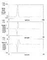
- the time associated with aortic valve closingalso known as the “X point” is generally determined as the time associated with the inverted derivative global minimum, which occurs after the C point, as illustrated in FIG. 1 .
- the so-called “O point”may be of utility in the analysis of the cardiac muscle.
- the O pointrepresents the time of opening of the mitral valve of the heart.
- the O pointis generally determined as the time associated with the first peak after the X point.
- the time difference between aortic valve closing and mitral valve openingis known as the isovolumetric relaxation time, IVRT.
- IVRTisovolumetric relaxation time
- Impedance cardiographyfurther requires recording of the subject's electrocardiogram (ECG) in conjunction with the thoracic impedance waveform previously described.
- ECGelectrocardiogram
- Processing of the impedance waveform for hemodynamic analysisrequires the use of ECG fiducial points as landmarks. Processing of the impedance waveform is generally performed on a beat-by-beat basis, with the ECG being used for beat detection.
- detection of some fiducial points of the impedance signalmay require the use of ECG fiducial points as landmarks.
- individual beatsare identified by detecting the presence of QRS complexes within the ECG.
- the peak of the R wave(commonly referred to as the “R point”) in the QRS complex is also detected, as well as the onset of depolarization of the QRS complex (“Q point”).
- the aforementioned fiducial points in the impedance cardiography waveformi.e., B, C, O, and X points
- ECGi.e. R and Q points
- empirical curve fittingis not only labor intensive and subject to several potential sources of error, but, in the case of the impedance waveform, also requires elimination of respiratory artifact.
- digital signal processinghas been applied to the impedance cardiography waveform for pattern recognition.
- One mathematical technique used in conjunction with such processing, the well known time-frequency distributionutilizes complex mathematics and a well known time-frequency distribution (e.g., the spectrogram). See for example, U.S. Pat. Nos.
- the spectrogramis used for extraction of information relating to the transient behavior of the dZ/dt signal.
- a mixed time-frequency representation of the signalis generated through calculation of the Fast Fourier Transform and multiplication by a windowing function (e.g., Hamming function) to convert the one-dimensional discrete dZ/dt signal into a two-dimensional function with a time variable and frequency variable.
- a windowing functione.g., Hamming function
- the spectrogramsuffers from a significant disability relating to the introduction of cross term artifact into the pattern recognition calculations. Specifically, when a signal is decomposed, the time-frequency plane should accurately reflect this signal. If a signal is turned off for a finite time, some time-frequency distributions will not be zero during this time, due to the existence of interference cross terms inherent in the calculation of the distribution.
- spectrogramAnother limitation of the spectrogram is its assumption of stationarity within the windowing function. This assumption is valid if the frequency components are constant throughout the window.
- biological signalsincluding the ECG and the impedance waveform, are known to be non-stationary.
- the signal processing associated with such time-frequency distributionsby necessity incorporates complex mathematics (i.e., involves operands having both real and imaginary components), which significantly complicates even simple pattern recognition-related computations.
- an improved method and apparatus for assessing hemodynamic parameters, including cardiac output, within a living subjectwould ideally be completely non-invasive, accurate, easily adapted to the varying physiology of different subjects, and would produce reliable results under a variety of different operating conditions. Additionally, such improved method and apparatus would be based on comparatively simple mathematical operations and non-imaginary operands, thereby reducing the burden on associated signal processing hardware and software. Ideally, the effects of other potential sources of error (such as respiratory artifact) would also be mitigated or eliminated.
- the present inventionsatisfies the aforementioned needs by an improved method and apparatus for non-invasively assessing hemodynamic parameters, including cardiac output, within a living subject.
- an improved method of determining at least one hemodynamic parameter associated with a living subjectcomprises cardiac output
- the methodcomprises providing a plurality of electrodes disposed relative to the thoracic cavity of the subject; measuring at least one impedance waveform associated with the thoracic cavity using at least one of the plurality of electrodes; processing at least one impedance waveform using wavelet transforms to identify one or more fiducial points within the impedance waveform; and determining cardiac output based at least in part on the one or more fiducial points.
- the fiducial points of the ⁇ Z and dZ/dt waveformsare detected in the present invention using discrete wavelet transforms.
- the difference between each detected X and B pointis used in the present embodiment to calculate ventricular ejection time (LVET).
- the magnitude of the largest negative derivative of the impedance change occurring during systole (dZ/dt max )is calculated from the C point.
- LVET and dZ/dt maxare then used to calculate the stroke volume, from which cardiac output is derived.
- the wavelet transform methodology of the present inventionadvantageously requires only simple additions and multiplications of real numbers, thereby substantially simplifying the processing associated with the cardiac output (CO) determination. Furthermore, cross terms are minimized as part of the wavelet transform methodology of the present invention, thereby increasing the accuracy of the CO determination.
- the second waveformcomprises the electrocardiogram (ECG) of the subject
- the specific eventscomprise individual “beats” of the subject's cardiac muscle
- the methodcomprises measuring at least one ECG waveform using at least one of the plurality of electrodes; processing the at least one waveform using discrete wavelet transforms to identify one or more fiducial points within the ECG; identifying one or more QRS complexes based at least in part on the one or more fiducial points; and identifying beats based at least in part on the identified QRS complex(es).
- the peak of the R wave (R point) in the QRS complex as well as the onset of depolarization of the QRS complex (Q point)are also detected.
- the time interval between the R wavesis also used to calculate the heart rate.
- an improved computer programfor implementing the aforementioned methods of hemodynamic parametric assessment (e.g., determination of cardiac output from the impedance waveform, and identification of cardiac beats within the ECG) using discrete wavelet transforms.
- the computer programcomprises an object code representation of an assembly language source code listing, the object code representation being disposed on a transportable storage medium (e.g., floppy disk).
- the computer programis disposed on the discrete storage device of a signal processing apparatus and adapted to run on the digital processor thereof.
- the computer programfurther comprises a graphical user interface (GUI) operatively coupled to the display and input device of the signal processing apparatus.
- GUIgraphical user interface
- the computer programcomprises an instruction set disposed within the storage device (such as the embedded program memory) of the digital signal processor (DSP) of the signal processing apparatus.
- DSPdigital signal processor
- an improved apparatus for assessing one or more hemodynamic parameters associated with a living subjectcomprises the cardiac output of the subject, and the apparatus generally comprises a plurality of electrodes disposed in proximity to the thoracic cavity of the subject; a current source adapted to provide a predetermined current through the thoracic cavity of the subject via at least one of the plurality of electrodes; and a signal processing apparatus adapted to analyze the signals obtained from the electrodes and determine stroke volume (and accordingly cardiac output) therefrom.
- the signal processing apparatuscomprises a signal conditioning apparatus adapted to process signals (including the impedance signal(s) and ECG derived from one or more of the electrodes) and produce conditioned signals relating thereto; and a processor adapted to detect the fiducial points within the impedance signal(s) or conditioned signals using discrete wavelet transforms, from which cardiac output is ultimately determined.
- the apparatusfurther comprises an analog-to-digital converter which converts the analog signals to a binary digital format for use by the processor, the processor comprising a digital signal processor (DSP) adapted to run one or more of the aforementioned fiducial point detection computer programs thereon.
- DSPdigital signal processor
- the apparatusalso includes a random access memory (RAM) or other storage device in data communication with the processor for storing data prior to and/or after processing by the processor.
- an improved method of providing treatment to a subject using the aforementioned cardiac output assessment methodologygenerally comprises the steps of: disposing a plurality of electrodes with respect to the thoracic cavity of the subject; measuring the impedance and ECG data of the subject non-invasively; determining the stroke volume of the subject's cardiac muscle during at least one cardiac cycle using discrete wavelet transforms; determining the cardiac output of the subject based at least in part on the stroke volume, and providing treatment to the subject based on the determined cardiac output.
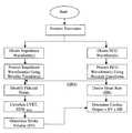
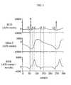
- FIG. 1is a graphical representation of the ECG, ⁇ Z and dZ/dt waveforms obtained from a typical living subject, illustrating the relative disposition of the various fiducial points therein.
- FIG. 2is a logical flow diagram illustrating one exemplary embodiment of the waveform analysis methodology of the present invention in the context of a cardiac output (CO) determination.
- COcardiac output
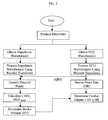
- FIG. 3is a logical flow diagram illustrating the methodology of FIG. 2 in greater detail, including pre-processing and fiducial point detection.
- FIG. 4is a graphical representation illustrating fiducial point detection in the impedance waveform of a volume loaded patient.
- FIG. 5is a logical block diagram illustrating the process of waveform filtering using scaling (lowpass) or wavelet filters (highpass) according to the invention.
- FIG. 6is a graph illustrating exemplary C point detection using the Mallet scaling filter, m A (k), according to the invention, acquired from a 62 year old, 82 kg male pacemaker patient.
- FIG. 7is a graph illustrating exemplary B point detection using the Symlet2 wavelet filter, s D (k), according to the invention.
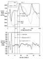
- FIG. 8is a graph illustrating exemplary X point detection using a new fiducial filter, f A (k), according to the invention.
- FIG. 9is a graph illustrating a typical group of beats used in validation.
- FIG. 10is a logical flow diagram illustrating one exemplary embodiment of the method of ECG QRS complex and fiducial point detection using wavelet transforms according to the invention.
- FIG. 11 ais a graph of an exemplary ECG waveform obtained from a living subject.
- FIG. 11 bis a graph of exemplary detail coefficients at scale 1, Y s1 , obtained from the ECG waveform of FIG. 11 a.
- FIG. 11 cis a graph of exemplary detail coefficients at scale 2, Y s2 , obtained from the ECG waveform of FIG. 11 a.
- FIG. 11 dis a graph of exemplary repeated detail coefficients at scale 1, WT s1 obtained from the ECG waveform of FIG. 11 a.
- FIG. 11 eis a graph of exemplary repeated detail coefficients at scale 2, WT s2 , obtained from the ECG waveform of FIG. 11 a.
- FIG. 11 fis a graph of exemplary intermediate test values, w T , obtained from the ECG waveform of FIG. 11 a.
- FIG. 11 gis a graph of exemplary wavelet test values, w T , obtained from the ECG waveform of FIG. 11 a.
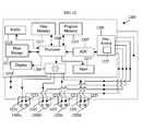
- FIG. 12is a block diagram of one exemplary embodiment of the apparatus for hemodynamic assessment according to the invention.
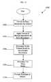
- FIG. 13is a logical flow diagram illustrating one exemplary embodiment of the method of providing treatment to a subject using the aforementioned methods.
- the inventionis described herein in terms of an apparatus and method for determining cardiac output suitable for use on the thorax of a human subject, the invention may also be embodied or adapted to monitor cardiac output at other locations on the human body, as well as monitoring cardiac output on other warm-blooded species such as, for example, primates, canines, or porcines. All such adaptations and alternate embodiments are considered to fall within the scope of the claims appended hereto.
- the present inventioncomprises a method of assessing hemodynamic parameters within a living subject through analysis of signals relating to the subject's physiology using discrete wavelet transforms.
- the present inventionis useful in accurately and non-invasively determining the stroke volume associated with the cardiac cycle of the subject, thereby advantageously allowing the accurate determination of the subject's cardiac output (CO).
- the QRS complex(es) present in the subject's ECG waveformare also detected using discrete wavelet transforms.
- a discrete wavelet transformis a time-scale representation of an input signal that is obtained by convolving the signal with a wavelet or scaling filter at a particular scale.
- Various wavelet and scaling filtersare utilized as part of the invention to emphasize certain features of interest associated with the input impedance and ECG waveforms obtained from electrodes positioned on the subject's thorax.
- the resulting emphasized feature in each wavelet transformis then detected to obtain a fiducial point (e.g., B, C, O, X for the impedance waveform, and Q or R for the ECG waveform).
- the difference between each detected X and B point in the impedance waveformis used to calculate ventricular ejection time (LVET), and dZ/dt max is calculated from the C point.
- LVET and dZ/dt maxare then used to calculate the stroke volume.
- the stroke volumeis then multiplied by the heart rate, which is determined from detection of the R point, to estimate CO. This general methodology is illustrated graphically
- the fiducial pointsare detected in the present invention on a “per-beat” basis (as opposed to over several beats).
- Each individual beat under considerationis divided by its Q points, where a Q point is equivalent to the start of the Q wave of the electrocardiogram QRS complex.
- Table 1below provides a summarization of the foregoing parameters related to cardiac output determination and QRS complex detection as used in relation to the present invention.
- LVET Left ventricular ejection timewhich is the time interval during which the aortic valve is open.
- Use of the discrete wavelet transform of the present inventionadvantageously (i) reduces the so-called “cross-term artifact” previously described with respect to the prior art time-frequency distribution approach, thereby increasing accuracy; (ii) is better suited for non-stationary signals, thereby localizing the fiducial points in time with more accuracy, and (iii) greatly simplifies the requisite processing associated with the SV and CO determinations, thereby increasing the speed of the computation, or conversely allowing the use of a reduced processor clock frequency or a lower MIPS device.
- the benefits of (iii)are especially useful in reducing the complexity and cost of the apparatus used to measure CO, as well as reducing the power consumption of the device and increasing battery longevity (such as in the case of a portable or hand-held unit).
- the method 300 processing of the impedance (Z) signal(s) obtained from the living subject to determine cardiac outputis described in greater detail.
- the ⁇ Z waveformis first bandpass filtered (step 302 ) and decimated (step 304 ). This produces a 200 Hz waveform, although it will be recognized that other nominal frequencies may be substituted.
- the time derivative of impedance, dZ/dtis calculated per step 308 , using 40 msec differences, although other time difference increments may be used as desired.
- the range of samples of ⁇ Z and dZ/dt that are used for B, C, X, and O detectionare identified as those samples between the two most recently detected Q points. This range is defined as shown in Eqn. 6:
- the typical order of occurrence of the fiducial pointsis: (i) the first Q point, (ii) R point, (iii) B point, (iv) C point, (v) X point, (vi) O point, and (vii) the second Q point, as illustrated in FIG. 1 .
- the B pointfollows the R point, where the R point is equivalent to the maximum deflection of the R wave of the electrocardiogram QRS complex.
- Accurate Q point detection of the ECGis important because it affects the fiducial point detection of the impedance waveform, and is also used in the calculation of the pre-ejection period. Detection of the QRS complex, and the Q and R points, is discussed in detail below with respect to FIGS. 10-11 g.
- this pointis detected first per step 310 of FIG. 3 .
- the B pointis then detected in step 312 from the sample range defined by ⁇ R point, C point ⁇ .
- the X pointis detected in step 314 from the sample range defined by ⁇ C point, second Q point ⁇ 1 ⁇ .
- the O pointis detected from the sample range ⁇ X point, (second Q point ⁇ 1) ⁇ in step 316 .
- the C pointis generally identified as the sample with the highest dZ/dt amplitude.
- volume loaded patientsi.e., those with increased intravascular volume such as hemodialysis patients immediately before scheduled dialysis
- the C pointis the sample associated with the first occurring peak. This relationship is illustrated in FIG. 4 .
- the B pointis generally identified as the sample associated with the onset of the rapid upstroke (a slight inflection) in dZ/dt before the occurrence of the C point. This inflection is created by a local minimum in ⁇ Z that occurs near the beginning of the ⁇ Z period, as illustrated in FIG. 4 .
- the X pointis generally identified as the sample associated with the global minimum, which occurs after the C point. As used herein, the term “global minimum” refers to the minimum value within a given range of samples. However, the global minimum may occur after the O point, as shown in FIG. 1 . Therefore, in the context of the present embodiment, the X point is the first “significant” local minimum that occurs after the C point, although other definitions may be applied.
- the O pointis generally identified as the sample associated with the first peak after the X point, as illustrated in FIGS. 1 and 4.
- dZ/dt maxis calculated from the C point per step 323 .
- a discrete wavelet transformis a time-scale representation of an input signal that is obtained by filtering the signal with a wavelet transform pair at a particular scale, j
- the wavelet transform pairis composed of a scaling filter and wavelet filter.
- the scaling filter, ⁇ A (k)acts as a lowpass filter, of the type known in the art to obtain wavelet transform approximation coefficients
- the wavelet filter, ⁇ D (k)acts as a highpass filter to obtain wavelet transform detail coefficients.
- WT(k, j ⁇ 1)is either a waveform signal at scale 0, x(k), or approximation coefficients at scale (j ⁇ 1).
- the output approximation or detail coefficients, WT(k,j)may be calculated using Eqn. 7.
- g(k)is the wavelet or scaling filter.
- Eqn. 7provides the basis for the wavelet transform calculations of the present embodiment.
- the present inventionadvantageously utilizes various wavelet and scaling filters (described in greater detail below) to emphasize certain features of an input signal.
- the resulting features in wavelet transform approximation or detail coefficientsare then detected to obtain one or more fiducial points associated with the input waveform(s). This process 500 is illustrated graphically in FIG. 5 .
- the C point of the impedance waveformis detected (step 310 of FIG. 3) from scale 1 approximation coefficients of dZ/dt, based on the Mallet scaling filter, as illustrated in FIG. 6 .
- the Mallet scaling filter, m A (k)may be defined as shown in Eqn. 8 below:
- m A ( k )⁇ 0.0132, ⁇ 0.0393, ⁇ 0.0450, 0.2864, 0.4347, 0.2864, 0.0450, ⁇ 0.0393, ⁇ 0.0132 ⁇ (Eqn. 8)
- Length, LThe total number of samples within the current Q-Q interval.
- Max3The dZ/dt sample corresponding to Max1 or Max2.
- Max3is determined according to the following logical relationships:
- C_pointthe sample associated with the maximum dZ/dt(k) value within the range ⁇ Max3 ⁇ 2, Max3+2 ⁇ .
- dZ/dt maxdZ/dt(C_point).
- the B pointis detected from scale 2 detail coefficients of ⁇ Z, based on an exemplary Symlet2 wavelet transform pair, illustrated in FIG. 7 .
- the Symlet2 scaling filter, S A (k)is defined as shown in Eqn. 11:
- the Symlet2 wavelet filter, S D (k),is defined as shown in Eqn. 12:
- scale 1 approximation coefficientsare first calculated using the scaling filter.
- scale 2 detail coefficientsare calculated from scale 1 approximation coefficients using the wavelet filter.
- the B pointis detected within the following sample range:
- R_pointThe sample associated with the maximum deflection in the QRS complex.
- Scale2_lengthThe number of scale 2 coefficients.
- a “peak”is defined in the present embodiment as the sample associated with a local maximum, in which the function values immediately before and after the value at this sample are smaller, although it will be recognized that other definitions may be applied. Based on this definition, the search for the most recent local maximum is conducted from the right to left samples to obtain Maxsample, unless the following relationship applies:
- the X pointis detected in the present embodiment from scale 1 approximation coefficients of dZ/dt, based on a sampled version of a new continuous wavelet transform function, as shown in FIG. 8 .
- the continuous wavelet transform functionis defined in Eqn. 14:
- the following exemplary input parametersare specified:
- i. dZ/dt(k)The first derivative of the impedance signal.
- C_pointThe sample associated with the maximum dZ/dt(k) value.
- X_point_foundFlag indicating whether X point is found. Set low if a valley is not found in the scale 1 approximation coefficient. Otherwise, set high.
- Threshold_out(i)(X_point ⁇ C_point).
- Threshold_out(i)(X_point ⁇ C_point).
- the O pointis detected in the present embodiment from scale 3 approximation coefficients of dZ/dt, based on the fiducial filter, as shown in FIG. 8 .
- i. dZ/dt(k)The first derivative of the impedance signal.
- ii. X_pointThe sample associated with the “significant” local minimum in dZ/dt(k).
- a peakis defined as the first increasing sample associated with a local maximum, in which the function values immediately before and after the value at this sample are less.
- O_pointThe O point shall be determined as the global maximum dZ/dt(k) value within the range
- the left ventricular ejection time(LVET) is calculated per step from the B and X_points.
- the following exemplary input parametersare specified for the LVET calculation:
- B_pointSample signifying initial aortic valve opening.
- ii. X_pointSample signifying aortic valve closing.
- sampling_intervaltime elapsed between consecutive samples
- LVET(i)The difference between the inputs, multiplied by the derivative sampling interval:
- the present inventionovercomes this disability through utilization of rejection criteria related primarily to median filtering.
- rejection criteriarelated primarily to median filtering.
- calculated values of LVET and dZ/dt maxare buffered in median filters that may shift with each successive beat.
- the output of each filteris the median value.
- individual beatsmay also be selectively rejected if the local features in the associated wavelet transforms are not present such that the X point cannot be detected.
- the input parameters for the illustrated embodiment of the median filtersare defined as follows:
- dZ/dt max (i)Most recent dZ/dt max estimate.
- LVET(i)Most recent LVET estimate.
- Beat_averageN Number of beats to average, as determined by the user.
- the median filter output parametersare defined as follows:
- dZ/dt max medmedian of dZ/dt max , calculated according to Eqn. 17:
- dZ/dt max medMEDIAN[dZ/dt max ( i ⁇ N+ 1). . . dZ/dt max ( i )], (Eqn. 17)
- ii. LVET medmedian of LVET, calculated according to Eqn. 18:
- LVET medMEDIAN[LVET ( i ⁇ N+ 1). . . LVET ( i )]. (Eqn. 18)
- individual beatsare further rejected if features are not found for proper X point detection.
- the following exemplary input parameteris specified for this rejection criterion:
- X_point_foundBit indicating that X point was detected (e.g., set high if X point detected).
- Median filteringMedian filtering on/off. If the X_point is not found, the calculated dZ/dt max (i) is not input to the dZ/dt max median filter, and a default LVET(i) is not input to the LVET median filter.
- the exemplary impedance waveform fiducial point detection algorithms described abovewere developed and tested largely from actual data obtained from living subjects. Specifically, the data used as the basis of development and testing comprised a training set of 48 waveforms; 10 waveforms were obtained from arrhythmic patients; 10 waveforms were obtained from canines; 10 waveforms contained noise artifact; and 10 waveforms were considered noise-free. The remaining 8 waveforms were obtained from low base impedance patients.
- Validation of this detectionwas performed by the Assignee hereof in a manner similar to the validation of QRS complexes during arrhythmias.
- Thirteen (13) test waveform setswere chosen randomly from a database of 266 waveforms, not used in training. Many of these waveforms possessed significant noise artifact. Additionally, 2 waveforms that exhibited bundle branch block, which occurs when the right and left ventricles do not simultaneously depolarize, were chosen. When this occurs, two R waves are present. None of the ECGs in the training data possessed bundle branch block.
- Fifteen (15) beats within each waveformwere annotated set for each fiducial point. The annotations were used as a reference for computing detection errors in the wavelet detection algorithm and in a previously released empirical detection algorithm. Specifically, the mean absolute value error percentages were computed for LVET and dZ/dt max .
- FIG. 9A typical group of beats selected for annotation is shown in FIG. 9 . Note that these beats are much noisier than the typical examples that appear in the literature, such as FIG. 1 . Based on 225 beats, LVET mean absolute error percentage decreased 48% from 19.3 to 10.0%, and dZ/dt max mean absolute error percentage decreased 37% from 3.0 to 1.9%, using the wavelet, rather than empirical, detection.
- the present inventionutilizes discrete wavelet transforms for QRS complex detection.
- QRS complexesare used to detect individual cardiac beats, and to initiate R and Q point detection.
- the R pointdenotes the maximum depolarization of the QRS complex
- the Q pointdenotes the start of the depolarization of the QRS complex.
- Beat detectionis also required to initiate fiducial point detection of the impedance waveform, as previously described. Accurate beat detection is also important in order to minimize the number of extraneous beats that are detected and the number of true beats that are missed, thereby increasing the accuracy of the technique.
- the present inventionuses the two smallest scales of the well known Haar wavelet, the wavelet with the smallest number of coefficients.
- the length of the input signal needed to calculate one value of the filtered outputis equivalent to the length of the filter. Therefore, the longer the filter, the longer the delay associated with the collection of the necessary input values.
- the number of multiplications needed to calculate one value of the filtered outputis equivalent to the length of the filter. Therefore, the longer the filter, the greater number of multiplications needed.
- a relative, rather than absolute, thresholdis used for QRS detection. This approach ensures that a QRS complex will be detected regardless of its amplitude.
- wavelet informationis used for the detection of a QRS complex only. Once a QRS complex has been detected, the R and Q points are detected using the time-based ECG values. This time-based detection allows these points to be better localized in time because these points can be found with better time resolution since wavelet transforms improve frequency localization at the expense of time localization.
- FIG. 10illustrates one exemplary embodiment of the signal processing methodology 1000 of the invention with respect to the ECG waveform.
- the ECG waveformis sampled at a nominal rate of 1000 Hz (step 1002 ).
- the sampled ECGis then lowpass filtered with frequency cutoff of 45 Hz (step 1004 ) and decimated to 200 Hz (step 1006 ).
- the resulting signalis then highpass filtered with a cutoff of 0.9 Hz (step 1008 ), and the amplitude of the signal is altered using an auto-gain scheme (step 1010 ).
- the auto-gainconverts the 21 bit value to a 16 bit value and then amplifies the signal as much as possible without saturating the 16 bits.
- the scale 1 and scale 2 coefficients for the resulting ECG signalare calculated (steps 1012 , 1014 ).
- An intermediate test valueis calculated therefrom (step 1024 ) by taking the square root of the absolute value of the product of the scale 1 and scale 2 coefficients of the ECG.
- the maximum value over the previous “i”e.g., 48
- the scale 1 and scale 2 coefficientsare chosen in the illustrated embodiment because these scales provide information about the high frequency content of a signal, generally associated with the QRS complex. Two scales are used in order to account for differences in frequency content across patients and pathologies.
- taking the maximum value over “i” (e.g., 48) sampleshelps to ignore spurious high frequency noise in the signal as well as noise from pacing spikes and high amplitude T waves, which can have overlapping frequency content.
- the wavelet transformis used in the present invention instead of a short-time Fourier transform (or spectrogram) because the wavelet transform provides, inter alia, better detection of non-stationary signals (signals with time-varying frequency components). This results in markedly improved time localization, and therefore better detection accuracy, of the QRS complex while decreasing the necessary computation.
- an ECG thresholdis defined by multiplying 0.10 and the maximum absolute value of the previous “j” ECG samples (here, the value of “j” is set at 300, although it will be appreciated that other values may be substituted). As described in greater detail below, this ECG threshold is used, together with a wavelet test value, to detect the onset of a QRS complex.
- the use of a relative, rather than an absolute, thresholdallows the algorithm to adjust for ECG amplitudes, which may be affected by factors such as electrode placement. This relative threshold further aids in the detection of low amplitude beats, and helps to ignore high amplitude noise in the ECG.
- the time at which it occurredis localized with better precision as part of step 1026 .
- the resultis a sample that occurs somewhere along the QRS complex. This localization is necessary because of the multiple (e.g., 48) samples over which the wavelet test value is calculated. This process helps reject artifacts, but also causes the QRS complex to be localized, at best, to an “i” sample (e.g., 48-sample) interval.
- the R pointis localized per step 1028 .
- the sample with the maximum absolute value of the ECG within a window located around the QRS complexis the location of the R point.
- R point detection per step 1028is described in greater detail below.
- the Q pointis next located within a window just prior to the R point (step 1031 ).
- the ECGis optionally signal-averaged within this window (step 1030 ) to decrease the impact of the high frequency noise in the Q point detection.
- This signal averagingmay be significant in certain applications, because the Q point is located along the baseline of the QRS, where the signal-to-noise ratio is lower than during the rest of the ECG.
- the peak of the Q waveis found.
- the beginning of depolarization of the QRS complexi.e. Q point
- the Q pointis further refined by searching within a window around the beginning of depolarization for the sample with the minimal deflection from the baseline.
- the sample at which the search for next subsequent QRS complex is disposedis calculated using the wavelet test value. This approach advantageously decreases unnecessary computation and helps reject undesirable artifact.
- Detection of the QRS complex, R point, and Q pointis accomplished using the Haar wavelet transform pair, which is composed of the Haar scaling filter, h A (k), and Haar wavelet filter, h D (k):
- Wavelet transformsconsisting of approximation or detail coefficients, are calculated, as per FIG. 5 .
- the sole input parameter for QRS complex detectioncomprises the 200 Hz ECG signal, x(k). Seven internal parameters are defined as follows:
- the exemplary Haar wavelet transformis used to find the detail coefficients at scale 1 of the ECG signal. This output is denoted as WT s1 (k), and is illustrated in FIG. 11 b.
- the Haar wavelet transformis used to find the detail coefficients at scale 2 of the ECG signal. This output is denoted as Y s2 (k), and is illustrated in FIG. 11 c.
- Each value of WT s1 ′(k)is repeated once as illustrated in FIG. 11 d .
- Each value of WT s2 (k)is repeated three times as illustrated in FIG. 11 e .
- Wavelet test value, W T(k)—The wavelet test value, W T , is calculated according to Eqns. 21 and 22 below:
- QRS threshold(vi) QRS threshold, threshold(k)—The QRS threshold is calculated according to Eqn. 23:
- QRS threshold crossing, crossing(k)The wavelet test value, w T , calculated in via Eqn. 22 above, is used to detect the presence of a QRS complex, using Eqns. 24 and 25 below:
- QRS complex locationk QRS (m)
- the location of the QRS complex within the QRS windowis first analyzed. Starting from the end of the window and decrementing by one sample until the start of the window has been reached, the first sample satisfying the condition w T (k) ⁇ w T (k+1) (if found) is identified.
- the default of location of the QRS complexis the start of the window.
- FIGS. 11 a - 11 gillustrate the foregoing processes graphically.
- R point detectionutilizes the nominal 200 Hz ECG signal, x(k) as the sole input parameter.
- the sole output parametercomprises the R point location, k R (m) where:
- the location of the R waveis defined as that sample in which the absolute value of the ECG signal is maximal within a window that starts at “a” samples before the QRS complex location and ends at “b” samples after the QRS complex location.
- Q point detectionutilizes the nominal 200 Hz ECG signal, x(k) as the sole input parameter.
- the sole internal parameter definedcomprises the signal-averaged version (step 1030 of FIG. 10) of the original 200 Hz ECG signal, X avg (k), where:
- ⁇ 100, where x avg is the signal-averaged ECGis found.
- the first sample k in which either Eqn. 26 or 27 below is validis found:
- the default kshall be 80 samples before the location of the R point.
- This sample, jis the location of the Q point, k Q (m).
- Detection of the next subsequent QRS complex(step 1034 of FIG. 10) according to the present embodiment utilizes the wavelet test value, w T (k), and the QRS threshold, threshold(k), as input parameters.
- the output parameterscomprise the sample number to begin looking for next QRS complex, k star (m+1), where:
- the waveformis analyzed to find the first sample k for which w T (k) ⁇ 3 ⁇ threshold(k).
- k start (m)occurs “m” (e.g., 48) samples past this first sample.
- rejection criteria documented hereare based on the acceptance of “good” beats in the training waveforms, and not, conversely, on the rejection of “bad” beats”, alternate rejection criteria based on “bad” beats, or even a combination or aggregation of either type of criteria, may be employed consistent with the invention.
- the ECG fiducial point detection algorithmwas developed and tested based on actual data obtained from living subjects.
- the datacomprised 23 previously collected patient files (146 waveforms total).
- the ECG fiducial point detection algorithmwas validated using the same 15 test files and methodology that were used to validate the impedance fiducial point detection algorithm. Based on 225 beats, Q point mean absolute error percentage decreased 88% from 79.3 to 9.4%, using the wavelet, rather than empirical, detection.
- the apparatusis adapted for the measurement of the cardiac output of a human being, although it will be recognized that other hemodynamic parameters and types of living organism may be evaluated in conjunction with the invention in its broadest sense.
- the apparatus 1200 of FIG. 12fundamentally comprises a plurality of electrically conductive electrodes 1202 (with individual terminals 1221 , 1223 ) for supplying a current and measuring voltage (and impedance) from the subject non-invasively; a current source 1204 coupled to at least a portion of the electrodes 1202 for providing the alternating (AC) electrical current supplied to the subject; discrete analog circuitry 1206 for preconditioning the analog impedance and ECG waveforms derived from the electrodes 1202 , an analog-to-digital converter (ADC) 1207 for converting the conditioned analog signals to a binary digital format; a digital processor 1208 operatively connected to the ADC 1207 for analyzing the digital representations of the conditioned ECG and impedance waveforms; a buffer memory 1210 for storing conditioned data prior to fiducial point detection; program and data memories 1211 , 1213 , for storing program instructions and data, respectively; a mass storage device 1215 , an input device 1217 for receiving operation command and data
- the electrodes 1202 of the embodiment of FIG. 12comprise so-called “spot” electrodes of the type well known in the medical arts, although it will be recognized that other types of electrodes, including band electrodes may be substituted.
- spot electrodeincludes both single- and multi-terminal electrodes adapted for use in a localized area of the subject's physiology. Exemplary configurations of the multi-terminal spot electrode especially useful with the invention herein are described in co-pending U.S. utility and design patent applications, Ser. Nos. 09/613,183 and 29/128,623 respectively, filed Jul. 10, 2000 and Aug. 28, 2000, respectively, both assigned to the Assignee hereof, both incorporated by reference herein in their entirety.
- the apparatus 1200In operation, the apparatus 1200 generates an effectively constant current (via the current source 1204 ) which is applied to certain ones of the terminal(s) 1221 of the electrodes 1202 .
- the applied current derived from the current source 1204is a 70 kHz sine wave of approximately 2.5 mA maximum RMS.
- the measured voltage associated with the aforementioned sine waveis on the order of 75 mV maximum RMS.
- the preprocessor 1206 and associated signal processing apparatusis in electrical communication with other electrodes 1202 , from which potentials (voltages) are measured.
- the typical impedance associated with a human subject's skinis 2 to 10 times the value of the underlying thoracic impedance Z T (t).
- the apparatus of the present inventionuses at least two, and typically four electrode arrays 1202 a-d for measurement, as shown in FIG. 12 .
- one electrode array 1202 acomprising a stimulation electrode terminal 1221 and a measurement electrode terminal 1223 is applied above the thorax of the subject, while a second electrode array 1202 b (similarly having a stimulation electrode terminal and measurement electrode terminal) is applied below the thorax.
- the AC current from the current sourceis supplied to the stimulation electrode terminals 1221 .
- the voltages at the measurement electrode terminals 1223are measured and input to a differential amplifier circuit 1227 within the preprocessor 1206 to obtain the differential voltage, V T (t).
- the desired thoracic impedance, Z T (t)is then obtained using the relationship of Eqn. 30.
- Z T ⁇ ( t )V T ⁇ ( t ) I T ⁇ ( t ) ( Eqn . ⁇ 30 )
- two sets of electrode arrays 1202 a-dmay advantageously be used to monitor the impedance associated with the left and right portion of the thorax in the present invention.
- the four measurement arraysare also used to obtain an electrocardiogram (ECG).
- ECGelectrocardiogram
- the Q wave of the ECG QRS intervalis used to, inter alia, determine the subject's heart rate, identify the QRS complex and Q and R points, and as an input to the fiducial point detection algorithm for the impedance waveform.
- the apparatus 1200 described hereinmay be constructed in a variety of different physical configurations, using a variety of different components, and measuring a variety of different hemodynamic parameters.
- some or even all of the foregoing componentsmay be physically integrated (such as in an application specific integrated circuit incorporating a DSP core, memory, “front” end analog processing, and ADC in a single piece of silicon), and/or the functionality associated with multiple components performed by a single multi-function component (e.g., a processor adapted to perform calculations associated with the wavelet transform methods disclosed herein, as well as host functions such as video display, bus arbitration, etc.).
- One exemplary configurationcomprises a PC-based device of the type well known in the art, having a host microprocessor as well as the aforementioned preprocessing and signal processing functionality in the form of a separate DSP in data communication therewith.
- the apparatuscomprises a mobile personal computing device (such as a personal digital assistant, or PDA), which is adapted to receive input data from the electrodes 1202 and analyze the data to produce a corrected measurement of cardiac output.
- PDApersonal digital assistant
- other portable devicessuch as laptop computers, calculators, and personal organizers, may conceivably be configured to run the computer program(s) of the present invention.
- Such portable devicesare readily adapted to the methods of the present invention, since as a result of the invention's advantageous use of comparatively simple wavelet transforms, the processing and storage capability needed to implement the algorithm is decreased. Furthermore, a variety of different methods of transmitting the input sensor (i.e., electrode) data to these devices may be used, including networked computers, or even wireless data links.
- cardiac output, LVET, SV, or other measurements generated by the foregoing apparatus 1200may also optionally be stored in the storage device 1215 for later retrieval, or output to an external device such as a printer, data storage unit, other peripheral component via a serial or parallel port if desired.
- the apparatus 1200may be networked to another computing device or database (not shown) whereby the data generated by the apparatus may be remotely analyzed or stored. Transmission of output data to such remote devices may be accomplished using a variety of well understood methods, such as by local area network (LAN), intranet, Internet, fiber-optic systems, or radio frequency (wireless) devices.
- LANlocal area network
- intranetintranet
- InternetInternet
- fiber-optic systemsfiber-optic systems
- wirelessradio frequency
- the apparatus 1200 of the inventionis described herein as a substantially discrete or “stand-alone” system, the invention may be adapted to act as a plug in card, module, or other complementary device (including any supporting software) for an existing ECG or patient monitoring system that utilizes electrodes.
- the inventioncan advantageously be “retrofitted” to such prior art systems, thereby extending the utility of the pre-existing system, and potentially obviating the purchase of entirely new equipment.
- the computer programcomprises an object (“machine”) code representation of an assembly source code listing implementing the discrete wavelet transform waveform analysis methodologies previously described herein, either individually or in combination thereof. While assembly language is used for the present embodiment, it will be appreciated that other programming languages may be used, including for example VisualBasicTM, Fortran, C, and C ++ .
- the object code representation of the source code listingis compiled and disposed on a media storage device of the type well known in the computer arts. Such media storage devices can include, without limitation, optical discs, CD ROMs, magnetic floppy disks or “hard” drives, tape drives, or even magnetic bubble memory.
- the computer programfurther comprises a graphical user interface (GUI) of the type well known in the programming arts, which is operatively coupled to the display and input device of the host computer or apparatus 1200 on which the program is run.
- GUIgraphical user interface
- the programis in one embodiment comprised of a series of subroutines or algorithms for implementing the methodologies described herein based on measured parametric data (e.g., the “input parameters” previously defined) which are provided to the host computer.
- the computer programcomprises an assembly language/micro-coded instruction set disposed within the embedded storage device, i.e. program memory, of a digital signal processor (DSP) or microprocessor associated with the foregoing hemodynamic measurement apparatus of FIG. 13 .
- DSPdigital signal processor
- FIG. 13a method of providing treatment to a subject using the aforementioned methods of wavelet transform fiducial point detection is described. While the following discussion is cast in terms of the aforementioned methods and algorithms adapted for determining cardiac output, it will be recognized that the method or providing treatment described herein is more broadly applicable to treatment based on the assessment of any hemodynamic property or parameter based on discrete wavelet transform analysis.
- the method of providing treatment 1300generally comprises first disposing a plurality of impedance cardiography electrodes with respect to the thoracic cavity of the subject per step 1302 .
- the electrodes 1202are the multi-terminal type described above with respect to FIG. 13 (or other suitable configuration), and are disposed above and below the thorax of the subject such that at least one stimulation terminal and one excitation terminal are above and below the thorax.
- the impedance waveform (and ECG) data of the subjectare measured non-invasively via the electrodes 1202 per step 1304 ; specifically by applying a constant AC waveform to the stimulation terminal(s), and measuring the resultant voltage at the measurement terminal(s).
- the stroke volume of the subject's cardiac muscle during at least one cardiac cycleis determined using discrete wavelet transforms as previously discussed herein. Specifically, after signal conditioning and pre-processing, the B, C, O, and X fiducial points are detected within the impedance waveform, and the QRS complex(es) and associated Q and R points are detected within the ECG waveforms, using the wavelet transforms. The stroke volume is then determined from the derived values of LVET and dZ/dt max . The cardiac output (CO) of the subject is next determined in step 1308 based on the stroke volume determined in step 1306 , and the heart rate (HR) derived from the subject from the ECG waveform.
- the cardiac output (CO) of the subjectis next determined in step 1308 based on the stroke volume determined in step 1306 , and the heart rate (HR) derived from the subject from the ECG waveform.
- a course of treatmentis determined and provided to the subject based on the cardiac output (CO) of step 1308 .
- Such course of treatmentmay include, for example, the intravenous injection of pharmacological agents, angioplasty, or other such measures aimed at increasing cardiac output or otherwise stemming further degradation of the subject's cardiac function.
Landscapes
- Health & Medical Sciences (AREA)
- Life Sciences & Earth Sciences (AREA)
- Engineering & Computer Science (AREA)
- Molecular Biology (AREA)
- Animal Behavior & Ethology (AREA)
- Veterinary Medicine (AREA)
- Biophysics (AREA)
- Pathology (AREA)
- Public Health (AREA)
- Biomedical Technology (AREA)
- Heart & Thoracic Surgery (AREA)
- Medical Informatics (AREA)
- General Health & Medical Sciences (AREA)
- Surgery (AREA)
- Physics & Mathematics (AREA)
- Cardiology (AREA)
- Physiology (AREA)
- Hematology (AREA)
- Artificial Intelligence (AREA)
- Computer Vision & Pattern Recognition (AREA)
- Psychiatry (AREA)
- Signal Processing (AREA)
- Nuclear Medicine, Radiotherapy & Molecular Imaging (AREA)
- Radiology & Medical Imaging (AREA)
- Measurement And Recording Of Electrical Phenomena And Electrical Characteristics Of The Living Body (AREA)
Abstract
Description


| TABLE 1 | |
| B point | Sample signifying initial aortic valve opening. |
| C point | Sample during which dZ/dt is maximum. |
| ΔZ | Time-varying portion of the impedance signal, which |
| is commonly inverted before further processing. | |
| dZ/dt | First derivative of the impedance signal. |
| dZ/dtmax | Maximum value of the first derivative of the impedance |
| signal. | |
| LVET | Left ventricular ejection time, which is the time interval |
| during which the aortic valve is open. | |
| O point | Sample during which the mitral valve opens. |
| Q point | Sample signifying initial ventricular depolarization. |
| R point | Sample signifying maximum deflection in QRS complex. |
| Sample, k | Digitized time. |
| X point | Sample during which the aortic valve closes. |


Claims (46)
Priority Applications (1)
| Application Number | Priority Date | Filing Date | Title |
|---|---|---|---|
| US09/764,589US6561986B2 (en) | 2001-01-17 | 2001-01-17 | Method and apparatus for hemodynamic assessment including fiducial point detection |
Applications Claiming Priority (1)
| Application Number | Priority Date | Filing Date | Title |
|---|---|---|---|
| US09/764,589US6561986B2 (en) | 2001-01-17 | 2001-01-17 | Method and apparatus for hemodynamic assessment including fiducial point detection |
Publications (2)
| Publication Number | Publication Date |
|---|---|
| US20020138014A1 US20020138014A1 (en) | 2002-09-26 |
| US6561986B2true US6561986B2 (en) | 2003-05-13 |
Family
ID=25071157
Family Applications (1)
| Application Number | Title | Priority Date | Filing Date |
|---|---|---|---|
| US09/764,589Expired - LifetimeUS6561986B2 (en) | 2001-01-17 | 2001-01-17 | Method and apparatus for hemodynamic assessment including fiducial point detection |
Country Status (1)
| Country | Link |
|---|---|
| US (1) | US6561986B2 (en) |
Cited By (147)
| Publication number | Priority date | Publication date | Assignee | Title |
|---|---|---|---|---|
| US20020147475A1 (en)* | 2001-04-10 | 2002-10-10 | Avram Scheiner | Cardiac rhythm management system for hypotension |
| US20020147476A1 (en)* | 2001-04-10 | 2002-10-10 | Daum Douglas R. | Cardiac rhythm management system adjusting rate response factor for treating hypotension |
| US20030028221A1 (en)* | 2001-07-31 | 2003-02-06 | Qingsheng Zhu | Cardiac rhythm management system for edema |
| US6749567B2 (en) | 2001-05-09 | 2004-06-15 | Hemonix, Inc. | Noninvasive method of measuring physiologic parameters |
| US20040116820A1 (en)* | 2002-12-13 | 2004-06-17 | Daum Douglas R. | Respiration signal measurement apparatus, systems, and methods |
| US20050004610A1 (en)* | 2003-07-02 | 2005-01-06 | Jaeho Kim | Cardiac cycle synchronized sampling of impedance signal |
| US20050004609A1 (en)* | 2003-07-02 | 2005-01-06 | Stahmann Jeffrey E. | Implantable devices and methods using frequency-domain analysis of thoracic signal |
| US20050096704A1 (en)* | 2003-10-29 | 2005-05-05 | Scott Freeberg | Cross-checking of transthoracic impedence and acceleration signals |
| US20050203427A1 (en)* | 2004-03-15 | 2005-09-15 | Impedance Vascular Imaging Products, Llc | Stenosis detection device |
| US20050215918A1 (en)* | 2004-03-24 | 2005-09-29 | Frantz Ann K | Thoracic impedance monitor and electrode array and method of use |
| US20050267381A1 (en)* | 2004-05-10 | 2005-12-01 | Transoma Medical, Inc. | Portable device for monitoring electrocardiographic signals and indices of blood flow |
| US20050283088A1 (en)* | 2004-06-16 | 2005-12-22 | Bernstein Donald P | Apparatus and method for determination of stroke volume using the brachial artery |
| US20060009710A1 (en)* | 2004-06-16 | 2006-01-12 | Bernstein Donald P | Apparatus and method for determination of stroke volume using the brachial artery |
| US20060020295A1 (en)* | 2004-07-23 | 2006-01-26 | Cardiac Pacemakers, Inc. | Method and apparatus for monitoring heart failure patients with cardiopulmonary comorbidities |
| US20060041280A1 (en)* | 2004-08-19 | 2006-02-23 | Cardiac Pacemakers, Inc. | Thoracic impedance detection with blood resistivity compensation |
| US7011631B2 (en) | 2003-01-21 | 2006-03-14 | Hemonix, Inc. | Noninvasive method of measuring blood density and hematocrit |
| WO2004082460A3 (en)* | 2003-03-14 | 2006-03-30 | Shock Llc | Methods of and apparatus for determining fluid volume presence in mammalian tissue |
| US20060084881A1 (en)* | 2004-10-20 | 2006-04-20 | Lev Korzinov | Monitoring physiological activity using partial state space reconstruction |
| US7043293B1 (en) | 2002-12-24 | 2006-05-09 | Cardiodynamics International Corporation | Method and apparatus for waveform assessment |
| US20060111642A1 (en)* | 2004-11-22 | 2006-05-25 | Baura Gail D | Method and apparatus for signal assessment including event rejection |
| US20060128193A1 (en)* | 2004-11-22 | 2006-06-15 | Cardiodynamics International Corporation | Methods and apparatus for conducting electrical current |
| US20060241513A1 (en)* | 2005-04-26 | 2006-10-26 | Cardiac Pacemakers, Inc. | Calibration of impedance monitoring of respiratory volumes using thoracic D.C. impedance |
| US20060247543A1 (en)* | 2002-10-09 | 2006-11-02 | Bruce Cornish | High resoution bio-impedance device |
| US20060258921A1 (en)* | 2003-02-27 | 2006-11-16 | Cardiodigital Limited | Method of analyzing and processing signals |
| US20060258952A1 (en)* | 2005-05-11 | 2006-11-16 | Cardiac Pacemakers, Inc. | Enhancements to the detection of pulmonary edema when using transthoracic impedance |
| US20060271024A1 (en)* | 2005-01-25 | 2006-11-30 | Michael Gertner | Nasal Cavity Treatment Apparatus |
| US20060293609A1 (en)* | 2005-05-11 | 2006-12-28 | Cardiac Pacemakers, Inc. | Sensitivity and specificity of pulmonary edema detection when using transthoracic impedance |
| US7251524B1 (en) | 2000-07-10 | 2007-07-31 | Cardiodynamics International Corporation | Apparatus and method for determining cardiac output in a living subject |
| US20070219453A1 (en)* | 2006-03-14 | 2007-09-20 | Michael Kremliovsky | Automated analysis of a cardiac signal based on dynamical characteristics of the cardiac signal |
| US20070260152A1 (en)* | 2006-05-05 | 2007-11-08 | Ghanem Raja N | Method and apparatus for discriminating cardiac signals in a medical device based on wavelet decomposition analysis |
| US7340296B2 (en) | 2005-05-18 | 2008-03-04 | Cardiac Pacemakers, Inc. | Detection of pleural effusion using transthoracic impedance |
| US20080103541A1 (en)* | 2002-04-03 | 2008-05-01 | Osypka Medical Gmbh | Method and apparatus for automatic determination of hemodynamically optimal cardiac pacing parameter values |
| US20080234594A1 (en)* | 2007-03-23 | 2008-09-25 | Brooks Donald J | Methods and apparatus for enhanced fiducial point determination and non-invasive hemodynamic parameter determination |
| US20080287823A1 (en)* | 2005-07-20 | 2008-11-20 | Scott Matthew Chetham | Index Determination |
| US20090043222A1 (en)* | 2005-10-11 | 2009-02-12 | Scott Chetham | Hydration status monitoring |
| US20090076398A1 (en)* | 2003-07-07 | 2009-03-19 | Nellcor Puritan Bennett Ireland | Continuous Non-Invasive Blood Pressure Measurement Apparatus and Methods Providing Automatic Recalibration |
| US20090143663A1 (en)* | 2005-07-01 | 2009-06-04 | Impedance Cardiology Systems Inc. | Pulmonary Monitoring System |
| US20090227858A1 (en)* | 2004-12-13 | 2009-09-10 | Koninklijke Philips Electronics N.V. | Cable with spacer for positioning multiple medical sensors |
| US20090326871A1 (en)* | 2008-06-30 | 2009-12-31 | Nellcor Puritan Bennett Ireland | Systems and methods for artifact detection in signals |
| US20090326393A1 (en)* | 2008-06-30 | 2009-12-31 | Nellcor Puritan Bennett Ireland | Systems and Methods for Non-Invasive Continuous Blood Pressure Determination |
| US20090326402A1 (en)* | 2008-06-30 | 2009-12-31 | Nellcor Puritan Bennett Ireland | Systems and methods for determining effort |
| US20090326353A1 (en)* | 2008-06-30 | 2009-12-31 | Nellcor Puritan Bennett Ireland | Processing and detecting baseline changes in signals |
| US20090324034A1 (en)* | 2008-06-30 | 2009-12-31 | Nellcor Puritan Bennett Ireland | Systems and methods for ridge selection in scalograms of signals |
| US20090326386A1 (en)* | 2008-06-30 | 2009-12-31 | Nellcor Puritan Bennett Ireland | Systems and Methods for Non-Invasive Blood Pressure Monitoring |
| US20090324033A1 (en)* | 2008-06-30 | 2009-12-31 | Nellcor Puritan Bennett Ireland | Signal Processing Systems and Methods for Determining Slope Using an Origin Point |
| US20100016696A1 (en)* | 2008-07-15 | 2010-01-21 | Nellcor Puritan Bennett Ireland | Systems and methods for generating reference signals |
| US20100016692A1 (en)* | 2008-07-15 | 2010-01-21 | Nellcor Puritan Bennett Ireland | Systems and methods for computing a physiological parameter using continuous wavelet transforms |
| US20100014724A1 (en)* | 2008-07-15 | 2010-01-21 | Nellcor Puritan Bennett Ireland, Mervue | Signal processing systems and methods using basis functions and wavelet transforms |
| US20100014725A1 (en)* | 2008-07-15 | 2010-01-21 | Nellcor Puritan Bennett Ireland | Systems And Methods For Filtering A Signal Using A Continuous Wavelet Transform |
| US20100017142A1 (en)* | 2008-07-15 | 2010-01-21 | Nellcor Puritan Bennett Ireland | Low Perfusion Signal Processing Systems And Methods |
| US20100016680A1 (en)* | 2008-07-15 | 2010-01-21 | Nellcor Puritan Bennett Ireland | Signal Processing Systems and Methods for Analyzing Multiparameter Spaces to Determine Physiological States |
| US20100014761A1 (en)* | 2008-06-30 | 2010-01-21 | Nellcor Puritan Bennett Llc | Methods And Systems For Discriminating Bands In Scalograms |
| US20100013642A1 (en)* | 2008-07-15 | 2010-01-21 | Nellcor Puritan Bennett Ireland | Systems And Methods For Evaluating A Physiological Condition |
| US20100016691A1 (en)* | 2008-07-15 | 2010-01-21 | Nellcor Puritan Bennett Ireland | Methods And Systems For Determining Whether To trigger An Alarm |
| US20100036231A1 (en)* | 2008-08-08 | 2010-02-11 | Anatolie Hobet | Electrical connector apparatus and methods |
| US20100081943A1 (en)* | 2008-09-30 | 2010-04-01 | Nellcor Puritan Bennett Ireland | Detecting Sleep Events Using Localized Blood Pressure Changes |
| US20100081944A1 (en)* | 2008-09-30 | 2010-04-01 | Nellcor Puritan Bennett Ireland | Systems and Methods for Recalibrating a Non-Invasive Blood Pressure Monitor |
| US20100081898A1 (en)* | 2008-09-30 | 2010-04-01 | Nellcor Puritan Bennett Ireland | Detecting A Probe-Off Event In A Measurement System |
| US20100081940A1 (en)* | 2008-09-30 | 2010-04-01 | Nellcor Puritan Bennett Llc | Laser Self-Mixing Sensors for Biological Sensing |
| US20100081960A1 (en)* | 2008-09-30 | 2010-04-01 | Nellcor Puritan Bennett Llc | Bioimpedance System and Sensor and Technique for Using the Same |
| US20100079279A1 (en)* | 2008-09-30 | 2010-04-01 | Nellcor Puritan Bennett Ireland | Detecting a Signal Quality Decrease in a Measurement System |
| US20100081945A1 (en)* | 2008-09-30 | 2010-04-01 | Nellcor Puritan Bennett Ireland | Systems and Methods for Maintaining Blood Pressure Monitor Calibration |
| US20100087714A1 (en)* | 2008-10-03 | 2010-04-08 | Nellcor Puritan Bennett Ireland | Reducing cross-talk in a measurement system |
| US20100113904A1 (en)* | 2008-11-05 | 2010-05-06 | Nellcor Puritan Bennett Llc | System And Method For Facilitating Observation Of Monitored Physiologic Data |
| US20100204599A1 (en)* | 2009-02-10 | 2010-08-12 | Cardionet, Inc. | Locating fiducial points in a physiological signal |
| US20100298676A1 (en)* | 2009-05-20 | 2010-11-25 | Nellcor Puritan Bennett Ireland | Estimating Transform Values Using Signal Estimates |
| US20100298728A1 (en)* | 2009-05-20 | 2010-11-25 | Nellcor Puritan Bennett Ireland | Signal Processing Techniques For Determining Signal Quality Using A Wavelet Transform Ratio Surface |
| US20100312075A1 (en)* | 2009-06-09 | 2010-12-09 | Nellcor Puritan Bennett Ireland | Signal Processing Techniques For Aiding The Interpretation Of Respiration Signals |
| US7850616B1 (en)* | 2005-06-15 | 2010-12-14 | Pacesetter, Inc. | Determination of diastolic heart failure |
| US20100324827A1 (en)* | 2009-06-18 | 2010-12-23 | Nellcor Puritan Bennett Ireland | Fluid Responsiveness Measure |
| US20100324431A1 (en)* | 2009-06-18 | 2010-12-23 | Nellcor Puritan Bennett Ireland | Determining Disease State Using An Induced Load |
| US20100331716A1 (en)* | 2009-06-26 | 2010-12-30 | Nellcor Puritan Bennett Ireland | Methods and apparatus for measuring respiratory function using an effort signal |
| US20100331715A1 (en)* | 2009-06-30 | 2010-12-30 | Nellcor Puritan Bennett Ireland | Systems and methods for detecting effort events |
| US20100331724A1 (en)* | 2009-06-30 | 2010-12-30 | Nellcor Puritan Bennett Ireland | Determining a characteristic blood pressure |
| US20110004069A1 (en)* | 2009-07-06 | 2011-01-06 | Nellcor Puritan Bennett Ireland | Systems And Methods For Processing Physiological Signals In Wavelet Space |
| US20110021892A1 (en)* | 2009-07-23 | 2011-01-27 | Nellcor Puritan Bennett Ireland | Systems and methods for respiration monitoring |
| US20110021941A1 (en)* | 2009-07-23 | 2011-01-27 | Nellcor Puritan Bennett Ireland | Systems and methods for respiration monitoring |
| US20110021929A1 (en)* | 2009-07-27 | 2011-01-27 | Nellcor Puritan Bennett Ireland | Systems and methods for continuous non-invasive blood pressure monitoring |
| US20110028810A1 (en)* | 2009-07-30 | 2011-02-03 | Nellcor Puritan Bennett Ireland | Systems And Methods For Resolving The Continuous Wavelet Transform Of A Signal |
| US20110026784A1 (en)* | 2009-07-30 | 2011-02-03 | Nellcor Puritan Bennett Ireland | Systems And Methods For Determining Physiological Information Using Selective Transform Data |
| US20110028813A1 (en)* | 2009-07-30 | 2011-02-03 | Nellcor Puritan Bennett Ireland | Systems And Methods For Estimating Values Of A Continuous Wavelet Transform |
| US20110066040A1 (en)* | 2009-09-16 | 2011-03-17 | Analogic Corporation | Physiologic parameter monitoring apparatus |
| US20110071406A1 (en)* | 2009-09-21 | 2011-03-24 | Nellcor Puritan Bennett Ireland | Determining A Characteristic Respiration Rate |
| US20110071376A1 (en)* | 2009-09-24 | 2011-03-24 | Nellcor Puritan Bennett Llc | Determination Of A Physiological Parameter |
| US20110071366A1 (en)* | 2009-09-24 | 2011-03-24 | Nellcor Puritan Bennett Llc | Determination Of A Physiological Parameter |
| US20110077484A1 (en)* | 2009-09-30 | 2011-03-31 | Nellcor Puritan Bennett Ireland | Systems And Methods For Identifying Non-Corrupted Signal Segments For Use In Determining Physiological Parameters |
| US20110077486A1 (en)* | 2009-09-30 | 2011-03-31 | Nellcor Puritan Bennett Ireland | Systems and methods for normalizing a plethysmograph signal for improved feature analysis |
| US20110074409A1 (en)* | 2009-09-25 | 2011-03-31 | Nellcor Puritan Bennett Ireland | Systems And Methods For Gating An Imaging Device |
| US20110098933A1 (en)* | 2009-10-26 | 2011-04-28 | Nellcor Puritan Bennett Ireland | Systems And Methods For Processing Oximetry Signals Using Least Median Squares Techniques |
| US7944551B2 (en) | 2008-06-30 | 2011-05-17 | Nellcor Puritan Bennett Ireland | Systems and methods for a wavelet transform viewer |
| US20110201951A1 (en)* | 2010-02-12 | 2011-08-18 | Siemens Medical Solutions Usa, Inc. | System for cardiac arrhythmia detection and characterization |
| US8068906B2 (en) | 2004-06-21 | 2011-11-29 | Aorora Technologies Pty Ltd | Cardiac monitoring system |
| US8209011B2 (en) | 2002-12-30 | 2012-06-26 | Cardiac Pacemakers, Inc. | Automatically configurable minute ventilation sensor |
| US8216136B2 (en) | 2009-03-05 | 2012-07-10 | Nellcor Puritan Bennett Llc | Systems and methods for monitoring heart rate and blood pressure correlation |
| US8233974B2 (en) | 1999-06-22 | 2012-07-31 | Impedimed Limited | Method and device for measuring tissue oedema |
| US8285352B2 (en) | 2008-07-15 | 2012-10-09 | Nellcor Puritan Bennett Llc | Systems and methods for identifying pulse rates |
| US8290730B2 (en) | 2009-06-30 | 2012-10-16 | Nellcor Puritan Bennett Ireland | Systems and methods for assessing measurements in physiological monitoring devices |
| US8506498B2 (en) | 2008-07-15 | 2013-08-13 | Nellcor Puritan Bennett Ireland | Systems and methods using induced perturbation to determine physiological parameters |
| US8628477B2 (en) | 2009-07-31 | 2014-01-14 | Nellcor Puritan Bennett Ireland | Systems and methods for non-invasive determination of blood pressure |
| US8679027B2 (en) | 2008-07-15 | 2014-03-25 | Nellcor Puritan Bennett Ireland | Systems and methods for pulse processing |
| US8700121B2 (en) | 2011-12-14 | 2014-04-15 | Intersection Medical, Inc. | Devices for determining the relative spatial change in subsurface resistivities across frequencies in tissue |
| US8755854B2 (en) | 2009-07-31 | 2014-06-17 | Nellcor Puritan Bennett Ireland | Methods and apparatus for producing and using lightly filtered photoplethysmograph signals |
| US8755871B2 (en) | 2011-11-30 | 2014-06-17 | Covidien Lp | Systems and methods for detecting arrhythmia from a physiological signal |
| US8761855B2 (en) | 2008-07-15 | 2014-06-24 | Nellcor Puritan Bennett Ireland | Systems and methods for determining oxygen saturation |
| US8761870B2 (en) | 2006-05-30 | 2014-06-24 | Impedimed Limited | Impedance measurements |
| US8825428B2 (en) | 2010-11-30 | 2014-09-02 | Neilcor Puritan Bennett Ireland | Methods and systems for recalibrating a blood pressure monitor with memory |
| US8834378B2 (en) | 2010-07-30 | 2014-09-16 | Nellcor Puritan Bennett Ireland | Systems and methods for determining respiratory effort |
| US8880576B2 (en) | 2011-09-23 | 2014-11-04 | Nellcor Puritan Bennett Ireland | Systems and methods for determining respiration information from a photoplethysmograph |
| US8898037B2 (en) | 2010-04-28 | 2014-11-25 | Nellcor Puritan Bennett Ireland | Systems and methods for signal monitoring using Lissajous figures |
| US9011347B2 (en) | 2008-10-03 | 2015-04-21 | Nellcor Puritan Bennett Ireland | Methods and apparatus for determining breathing effort characteristics measures |
| US9050043B2 (en) | 2010-05-04 | 2015-06-09 | Nellcor Puritan Bennett Ireland | Systems and methods for wavelet transform scale-dependent multiple-archetyping |
| US9049994B2 (en) | 2011-09-21 | 2015-06-09 | Siemens Medical Solutions Usa, Inc. | System for cardiac arrhythmia detection and characterization |
| US9060695B2 (en) | 2011-11-30 | 2015-06-23 | Covidien Lp | Systems and methods for determining differential pulse transit time from the phase difference of two analog plethysmographs |
| US9066660B2 (en) | 2009-09-29 | 2015-06-30 | Nellcor Puritan Bennett Ireland | Systems and methods for high-pass filtering a photoplethysmograph signal |
| US9113830B2 (en) | 2011-05-31 | 2015-08-25 | Nellcor Puritan Bennett Ireland | Systems and methods for detecting and monitoring arrhythmias using the PPG |
| US9119597B2 (en) | 2011-09-23 | 2015-09-01 | Nellcor Puritan Bennett Ireland | Systems and methods for determining respiration information from a photoplethysmograph |
| US9155493B2 (en) | 2008-10-03 | 2015-10-13 | Nellcor Puritan Bennett Ireland | Methods and apparatus for calibrating respiratory effort from photoplethysmograph signals |
| US9179876B2 (en) | 2012-04-30 | 2015-11-10 | Nellcor Puritan Bennett Ireland | Systems and methods for identifying portions of a physiological signal usable for determining physiological information |
| US9211110B2 (en) | 2013-03-15 | 2015-12-15 | The Regents Of The University Of Michigan | Lung ventillation measurements using ultrasound |
| US9247896B2 (en) | 2012-01-04 | 2016-02-02 | Nellcor Puritan Bennett Ireland | Systems and methods for determining respiration information using phase locked loop |
| US9259160B2 (en) | 2010-12-01 | 2016-02-16 | Nellcor Puritan Bennett Ireland | Systems and methods for determining when to measure a physiological parameter |
| US9326735B2 (en) | 2012-05-15 | 2016-05-03 | Koninklijke Philips N.V. | Method and apparatus for monitoring cardiac output of a patient in a home environment |
| US9357934B2 (en) | 2010-12-01 | 2016-06-07 | Nellcor Puritan Bennett Ireland | Systems and methods for physiological event marking |
| US9402554B2 (en) | 2011-09-23 | 2016-08-02 | Nellcor Puritan Bennett Ireland | Systems and methods for determining respiration information from a photoplethysmograph |
| US9451887B2 (en) | 2010-03-31 | 2016-09-27 | Nellcor Puritan Bennett Ireland | Systems and methods for measuring electromechanical delay of the heart |
| US9504406B2 (en) | 2006-11-30 | 2016-11-29 | Impedimed Limited | Measurement apparatus |
| US9554712B2 (en) | 2013-02-27 | 2017-01-31 | Covidien Lp | Systems and methods for generating an artificial photoplethysmograph signal |
| US9560978B2 (en) | 2013-02-05 | 2017-02-07 | Covidien Lp | Systems and methods for determining respiration information from a physiological signal using amplitude demodulation |
| US9585593B2 (en) | 2009-11-18 | 2017-03-07 | Chung Shing Fan | Signal distribution for patient-electrode measurements |
| US9597022B2 (en) | 2011-09-09 | 2017-03-21 | Nellcor Puritan Bennett Ireland | Venous oxygen saturation systems and methods |
| US9615767B2 (en) | 2009-10-26 | 2017-04-11 | Impedimed Limited | Fluid level indicator determination |
| US9615766B2 (en) | 2008-11-28 | 2017-04-11 | Impedimed Limited | Impedance measurement process |
| US9675274B2 (en) | 2011-09-23 | 2017-06-13 | Nellcor Puritan Bennett Ireland | Systems and methods for determining respiration information from a photoplethysmograph |
| US9687159B2 (en) | 2013-02-27 | 2017-06-27 | Covidien Lp | Systems and methods for determining physiological information by identifying fiducial points in a physiological signal |
| US9693736B2 (en) | 2011-11-30 | 2017-07-04 | Nellcor Puritan Bennett Ireland | Systems and methods for determining respiration information using historical distribution |
| US9693709B2 (en) | 2011-09-23 | 2017-07-04 | Nellcot Puritan Bennett Ireland | Systems and methods for determining respiration information from a photoplethysmograph |
| US9848820B2 (en) | 2014-01-07 | 2017-12-26 | Covidien Lp | Apnea analysis system and method |
| US9901308B2 (en) | 2014-02-20 | 2018-02-27 | Covidien Lp | Systems and methods for filtering autocorrelation peaks and detecting harmonics |
| US9955894B2 (en) | 2014-01-28 | 2018-05-01 | Covidien Lp | Non-stationary feature relationship parameters for awareness monitoring |
| US9974468B2 (en) | 2013-03-15 | 2018-05-22 | Covidien Lp | Systems and methods for identifying a medically monitored patient |
| US10022068B2 (en) | 2013-10-28 | 2018-07-17 | Covidien Lp | Systems and methods for detecting held breath events |
| US10070800B2 (en) | 2007-08-09 | 2018-09-11 | Impedimed Limited | Impedance measurement process |
| US10307074B2 (en) | 2007-04-20 | 2019-06-04 | Impedimed Limited | Monitoring system and probe |
| US10448851B2 (en) | 2012-09-11 | 2019-10-22 | Covidien Lp | System and method for determining stroke volume of a patient |
| US11419533B2 (en)* | 2015-04-29 | 2022-08-23 | The Cleveland Clinic Foundation | Bladder event detection for diagnosis of urinary incontinence or treatment of lower urinary tract dysfunction |
| US11660013B2 (en) | 2005-07-01 | 2023-05-30 | Impedimed Limited | Monitoring system |
| US11737678B2 (en) | 2005-07-01 | 2023-08-29 | Impedimed Limited | Monitoring system |
Families Citing this family (38)
| Publication number | Priority date | Publication date | Assignee | Title |
|---|---|---|---|---|
| US7758503B2 (en) | 1997-01-27 | 2010-07-20 | Lynn Lawrence A | Microprocessor system for the analysis of physiologic and financial datasets |
| US20060161071A1 (en)* | 1997-01-27 | 2006-07-20 | Lynn Lawrence A | Time series objectification system and method |
| US8932227B2 (en) | 2000-07-28 | 2015-01-13 | Lawrence A. Lynn | System and method for CO2 and oximetry integration |
| US9042952B2 (en) | 1997-01-27 | 2015-05-26 | Lawrence A. Lynn | System and method for automatic detection of a plurality of SPO2 time series pattern types |
| US9521971B2 (en) | 1997-07-14 | 2016-12-20 | Lawrence A. Lynn | System and method for automatic detection of a plurality of SPO2 time series pattern types |
| US20070191697A1 (en) | 2006-02-10 | 2007-08-16 | Lynn Lawrence A | System and method for SPO2 instability detection and quantification |
| US9053222B2 (en) | 2002-05-17 | 2015-06-09 | Lawrence A. Lynn | Patient safety processor |
| US20060195041A1 (en) | 2002-05-17 | 2006-08-31 | Lynn Lawrence A | Centralized hospital monitoring system for automatically detecting upper airway instability and for preventing and aborting adverse drug reactions |
| US8790272B2 (en)* | 2002-03-26 | 2014-07-29 | Adidas Ag | Method and system for extracting cardiac parameters from plethysmographic signals |
| US20040032426A1 (en)* | 2002-04-23 | 2004-02-19 | Jolyn Rutledge | System and user interface for adaptively presenting a trend indicative display of patient medical parameters |
| NL1024860C2 (en)* | 2003-11-24 | 2005-05-26 | Brainquiry B V | System is for recording electrical signals occurring in living body and has at least two electrodes for obtaining first analogue signal corresponding with electrical signal occurring in living body |
| US20050124901A1 (en)* | 2003-12-05 | 2005-06-09 | Misczynski Dale J. | Method and apparatus for electrophysiological and hemodynamic real-time assessment of cardiovascular fitness of a user |
| US7684856B2 (en)* | 2005-12-12 | 2010-03-23 | General Electric Company | Detection of artifacts in bioelectric signals |
| US20070135727A1 (en)* | 2005-12-12 | 2007-06-14 | Juha Virtanen | Detection of artifacts in bioelectric signals |
| US7668579B2 (en) | 2006-02-10 | 2010-02-23 | Lynn Lawrence A | System and method for the detection of physiologic response to stimulation |
| EP2035083B1 (en) | 2006-06-21 | 2012-08-08 | St. Jude Medical AB | Medical device and system for determining a hemodynamic parameter using intracardiac impedance |
| US20090216144A1 (en)* | 2008-02-25 | 2009-08-27 | Bruce Hopenfeld | Hopping methods for the detection of QRS onset and offset |
| JP5474937B2 (en) | 2008-05-07 | 2014-04-16 | ローレンス エー. リン, | Medical disorder pattern search engine |
| EP2375973A4 (en)* | 2008-12-16 | 2014-02-12 | Bodymedia Inc | METHOD AND APPARATUS FOR DETERMINING HEART RATE VARIABILITY USING WAVELET TRANSFORMATION |
| WO2010117572A2 (en)* | 2009-04-08 | 2010-10-14 | Virginia Commonwealth University | Combining predictive capabilities of transcranial doppler (tcd) with electrocardiogram (ecg) to predict hemorrhagic shock |
| US10722132B2 (en)* | 2010-12-28 | 2020-07-28 | Sotera Wireless, Inc. | Body-worn system for continuous, noninvasive measurement of cardiac output, stroke volume, cardiac power, and blood pressure |
| CN103876733B (en)* | 2014-03-12 | 2016-06-29 | 西安交通大学 | For the system and method that cardiorespiratory system Phase synchronization is analyzed |
| US9538930B2 (en)* | 2014-06-05 | 2017-01-10 | Guangren CHEN | Linear multi-domain electrocardiogram |
| CN106456032B (en)* | 2014-06-05 | 2019-11-05 | 陈光人 | Systems and methods for detecting ECG sub-waveforms |
| US9545203B2 (en)* | 2014-06-05 | 2017-01-17 | Guangren Chen | Systems and methods for cardiomyocyte conduction speed mapping |
| US10542961B2 (en) | 2015-06-15 | 2020-01-28 | The Research Foundation For The State University Of New York | System and method for infrasonic cardiac monitoring |
| EP3703808B1 (en) | 2017-11-02 | 2023-04-05 | Cardiac Pacemakers, Inc. | Systems for his-bundle pacing |
| US11147516B2 (en)* | 2018-06-18 | 2021-10-19 | Analytics For Life Inc. | Methods and systems to quantify and remove asynchronous noise in biophysical signals |
| CN109171674A (en)* | 2018-09-20 | 2019-01-11 | 芯海科技(深圳)股份有限公司 | Toilet lid and hemodynamic parameter measurement method based on the toilet lid |
| CN109171675A (en)* | 2018-09-20 | 2019-01-11 | 芯海科技(深圳)股份有限公司 | A kind of wearable device and the hemodynamic parameter measurement method based on the equipment |
| CN109171677A (en)* | 2018-09-20 | 2019-01-11 | 芯海科技(深圳)股份有限公司 | A kind of Portable type measurement unit and the hemodynamic parameter measurement method based on the device |
| CN109171676A (en)* | 2018-09-20 | 2019-01-11 | 芯海科技(深圳)股份有限公司 | A kind of hemodynamic parameter measuring device and method |
| CN109907752B (en)* | 2019-03-04 | 2021-11-09 | 王量弘 | Electrocardiogram diagnosis and monitoring system for removing motion artifact interference and electrocardio characteristic detection |
| CN111387939B (en)* | 2020-03-06 | 2023-08-18 | 芯海科技(深圳)股份有限公司 | Method, device, computer equipment and storage medium for measuring heart displacement |
| KR102344494B1 (en)* | 2020-06-02 | 2021-12-29 | 주식회사 에이티센스 | Biosignal measuring apparatus, Method for detecting signal peaks in an electrocardiogram of detecting an effective peak using the complexity value around the peak in the wavelet transformed signals, and a computer program for performing the methods |
| CN111938640B (en)* | 2020-08-05 | 2023-02-07 | 深圳大学 | Method, device and storage medium for point C location of cardiac impedance differential signal |
| WO2023135586A1 (en)* | 2022-01-12 | 2023-07-20 | Vijendra Venkatesh | A system for detection and classification of cardiac diseases using custom deep neural network techniques |
| CN117694863B (en)* | 2024-02-05 | 2024-05-28 | 深圳市美林医疗科技有限公司 | Hemodynamic parameter evaluation device and medium |
Citations (20)
| Publication number | Priority date | Publication date | Assignee | Title |
|---|---|---|---|---|
| USRE30101E (en) | 1964-08-19 | 1979-09-25 | Regents Of The University Of Minnesota | Impedance plethysmograph |
| US4802491A (en) | 1986-07-30 | 1989-02-07 | Massachusetts Institute Of Technology | Method and apparatus for assessing myocardial electrical stability |
| US5010888A (en) | 1988-03-25 | 1991-04-30 | Arzco Medical Electronics, Inc. | Method and apparatus for detection of posterior ischemia |
| US5178154A (en)* | 1990-09-18 | 1993-01-12 | Sorba Medical Systems, Inc. | Impedance cardiograph and method of operation utilizing peak aligned ensemble averaging |
| US5277189A (en) | 1991-08-16 | 1994-01-11 | Nid, Inc. | Method and apparatus for the measurement and analysis of cardiac rates and amplitude variations |
| US5309917A (en) | 1991-09-12 | 1994-05-10 | Drexel University | System and method of impedance cardiography and heartbeat determination |
| US5311874A (en) | 1992-05-18 | 1994-05-17 | Cardiac Pacemakers, Inc. | Method for tachycardia discrimination |
| US5391199A (en) | 1993-07-20 | 1995-02-21 | Biosense, Inc. | Apparatus and method for treating cardiac arrhythmias |
| US5423326A (en) | 1991-09-12 | 1995-06-13 | Drexel University | Apparatus and method for measuring cardiac output |
| US5439483A (en) | 1993-10-21 | 1995-08-08 | Ventritex, Inc. | Method of quantifying cardiac fibrillation using wavelet transform |
| US5505209A (en) | 1994-07-07 | 1996-04-09 | Reining International, Ltd. | Impedance cardiograph apparatus and method |
| US5730142A (en) | 1996-12-04 | 1998-03-24 | Medtronic, Inc. | Method and apparatus for detecting tachycardia |
| US5895298A (en) | 1997-05-29 | 1999-04-20 | Biofield Corp. | DC biopotential electrode connector and connector condition sensor |
| US5902325A (en)* | 1994-11-30 | 1999-05-11 | Medtronic, Inc. | Method and apparatus for detecting cardiac capture |
| US5913826A (en) | 1996-06-12 | 1999-06-22 | K-One Technologies | Wideband external pulse cardiac monitor |
| US5967995A (en) | 1998-04-28 | 1999-10-19 | University Of Pittsburgh Of The Commonwealth System Of Higher Education | System for prediction of life-threatening cardiac arrhythmias |
| US6022322A (en)* | 1998-02-06 | 2000-02-08 | Intermedics Inc. | Non-invasive cardiorespiratory monitor with synchronized bioimpedance sensing |
| US6115628A (en) | 1999-03-29 | 2000-09-05 | Medtronic, Inc. | Method and apparatus for filtering electrocardiogram (ECG) signals to remove bad cycle information and for use of physiologic signals determined from said filtered ECG signals |
| US6128526A (en) | 1999-03-29 | 2000-10-03 | Medtronic, Inc. | Method for ischemia detection and apparatus for using same |
| US6186955B1 (en) | 1998-11-16 | 2001-02-13 | Gail D. Baura | Noninvasive continuous cardiac output monitor |
- 2001
- 2001-01-17USUS09/764,589patent/US6561986B2/ennot_activeExpired - Lifetime
Patent Citations (25)
| Publication number | Priority date | Publication date | Assignee | Title |
|---|---|---|---|---|
| USRE30101E (en) | 1964-08-19 | 1979-09-25 | Regents Of The University Of Minnesota | Impedance plethysmograph |
| US4802491A (en) | 1986-07-30 | 1989-02-07 | Massachusetts Institute Of Technology | Method and apparatus for assessing myocardial electrical stability |
| US5010888A (en) | 1988-03-25 | 1991-04-30 | Arzco Medical Electronics, Inc. | Method and apparatus for detection of posterior ischemia |
| US5178154A (en)* | 1990-09-18 | 1993-01-12 | Sorba Medical Systems, Inc. | Impedance cardiograph and method of operation utilizing peak aligned ensemble averaging |
| US5277189A (en) | 1991-08-16 | 1994-01-11 | Nid, Inc. | Method and apparatus for the measurement and analysis of cardiac rates and amplitude variations |
| US5443073A (en) | 1991-09-12 | 1995-08-22 | Drexel University | System and method of impedance cardiography monitoring |
| US5309917A (en) | 1991-09-12 | 1994-05-10 | Drexel University | System and method of impedance cardiography and heartbeat determination |
| US5423326A (en) | 1991-09-12 | 1995-06-13 | Drexel University | Apparatus and method for measuring cardiac output |
| US5311874A (en) | 1992-05-18 | 1994-05-17 | Cardiac Pacemakers, Inc. | Method for tachycardia discrimination |
| US5546951A (en) | 1993-07-20 | 1996-08-20 | Biosense, Inc. | Method and apparatus for studying cardiac arrhythmias |
| US5391199A (en) | 1993-07-20 | 1995-02-21 | Biosense, Inc. | Apparatus and method for treating cardiac arrhythmias |
| US5439483A (en) | 1993-10-21 | 1995-08-08 | Ventritex, Inc. | Method of quantifying cardiac fibrillation using wavelet transform |
| US5505209A (en) | 1994-07-07 | 1996-04-09 | Reining International, Ltd. | Impedance cardiograph apparatus and method |
| US5902325A (en)* | 1994-11-30 | 1999-05-11 | Medtronic, Inc. | Method and apparatus for detecting cardiac capture |
| US5913826A (en) | 1996-06-12 | 1999-06-22 | K-One Technologies | Wideband external pulse cardiac monitor |
| US5730142A (en) | 1996-12-04 | 1998-03-24 | Medtronic, Inc. | Method and apparatus for detecting tachycardia |
| US5778881A (en) | 1996-12-04 | 1998-07-14 | Medtronic, Inc. | Method and apparatus for discriminating P and R waves |
| US5782888A (en) | 1996-12-04 | 1998-07-21 | Medtronic, Inc. | Method of selecting an operating mode for an implantable medical device |
| US5895298A (en) | 1997-05-29 | 1999-04-20 | Biofield Corp. | DC biopotential electrode connector and connector condition sensor |
| US6022322A (en)* | 1998-02-06 | 2000-02-08 | Intermedics Inc. | Non-invasive cardiorespiratory monitor with synchronized bioimpedance sensing |
| US6370424B1 (en)* | 1998-02-06 | 2002-04-09 | Intermedics Inc. | Non-invasive cardiorespiratory monitor with synchronized bioimpedance sensing |
| US5967995A (en) | 1998-04-28 | 1999-10-19 | University Of Pittsburgh Of The Commonwealth System Of Higher Education | System for prediction of life-threatening cardiac arrhythmias |
| US6186955B1 (en) | 1998-11-16 | 2001-02-13 | Gail D. Baura | Noninvasive continuous cardiac output monitor |
| US6115628A (en) | 1999-03-29 | 2000-09-05 | Medtronic, Inc. | Method and apparatus for filtering electrocardiogram (ECG) signals to remove bad cycle information and for use of physiologic signals determined from said filtered ECG signals |
| US6128526A (en) | 1999-03-29 | 2000-10-03 | Medtronic, Inc. | Method for ischemia detection and apparatus for using same |
Non-Patent Citations (10)
| Title |
|---|
| Afonso, V. X., et al., (1999), "ECG Beat Detection Using Filter Banks," IEEE Trans. BME, vol. 46, No. 2, pp. 838-848. |
| Application Ser. No. 09/613,183 entitled "Apparatus and Method for Determining Cardiac Output in a Living Subject," filed Jul. 10, 2000-Attorney Docket No. CARDIO.003A. |
| Bernstein, D.P., (1986), "A New Stroke Volume Equation for Thoracic Electrical Bioimpedance: Theory and Rationale," Critical Care Med., 14:904-909. |
| Kadambe, S., et al., (1995), "Wavelet Transform-Based QRS Complex Detector," IEEE Trans. BME, vol. 46, No. 7, pp. 838-848. |
| Kubicek, W.G., et al., (1966), "Development and Evaluation of An Impedance Cardiac Output System," Aerospace Med., 37:1208-1212. |
| Lababidi, Z., et al., (1970) "The First Derivative Thoracic Impedance Cardiogram," Circulation, 41:651-658. |
| Li, C., et al., (1995), "Detection of ECG Characteristic Points Using Wavelet Transforms," IEEE Trans. BME, vol. 42, No. 1, pp. 21-28. |
| Newman, D.G., et al., (1999), "The Non-Invasive Assessment of Stroke Volume and Cardiac Output by Impedance Cardiography: A Review," Aviation, Space, and Environmental Medicine, vol. 70, No. 8, pp. 780-789. |
| Nyboer, Jan, Sc.D. , M.D., et al., (1950), "Electrical Impedance Plethysmography," Circulation, vol. II, pp. 811-821. |
| Sramek, B.B., (1982), "Cardiac Output by Electrical Impedance," Med. Elect, 13:93-97. |
Cited By (270)
| Publication number | Priority date | Publication date | Assignee | Title |
|---|---|---|---|---|
| US8233974B2 (en) | 1999-06-22 | 2012-07-31 | Impedimed Limited | Method and device for measuring tissue oedema |
| US7251524B1 (en) | 2000-07-10 | 2007-07-31 | Cardiodynamics International Corporation | Apparatus and method for determining cardiac output in a living subject |
| US6907288B2 (en) | 2001-04-10 | 2005-06-14 | Cardiac Pacemakers, Inc. | Cardiac rhythm management system adjusting rate response factor for treating hypotension |
| US20020147476A1 (en)* | 2001-04-10 | 2002-10-10 | Daum Douglas R. | Cardiac rhythm management system adjusting rate response factor for treating hypotension |
| US20020147475A1 (en)* | 2001-04-10 | 2002-10-10 | Avram Scheiner | Cardiac rhythm management system for hypotension |
| US6912420B2 (en) | 2001-04-10 | 2005-06-28 | Cardiac Pacemakers, Inc. | Cardiac rhythm management system for hypotension |
| US6749567B2 (en) | 2001-05-09 | 2004-06-15 | Hemonix, Inc. | Noninvasive method of measuring physiologic parameters |
| US7191000B2 (en) | 2001-07-31 | 2007-03-13 | Cardiac Pacemakers, Inc. | Cardiac rhythm management system for edema |
| US9265950B2 (en) | 2001-07-31 | 2016-02-23 | Cardiac Pacemakers, Inc. | Contractility modulation based on impedance signal |
| US20030191503A1 (en)* | 2001-07-31 | 2003-10-09 | Cardiac Pacemakers, Inc. | Cardiac rhythm management system for edema |
| US20030028221A1 (en)* | 2001-07-31 | 2003-02-06 | Qingsheng Zhu | Cardiac rhythm management system for edema |
| US7177681B2 (en) | 2001-07-31 | 2007-02-13 | Cardiac Pacemakers, Inc. | Cardiac rhythm management system for edema |
| US20080215108A1 (en)* | 2001-07-31 | 2008-09-04 | Cardiac Pacemakers, Inc. | Cardiac rhythm management system for edema |
| US8219195B2 (en)* | 2002-04-03 | 2012-07-10 | Osypka Medical Gmbh | Method and apparatus for automatic determination of hemodynamically optimal cardiac pacing parameter values |
| US20080103541A1 (en)* | 2002-04-03 | 2008-05-01 | Osypka Medical Gmbh | Method and apparatus for automatic determination of hemodynamically optimal cardiac pacing parameter values |
| US20060247543A1 (en)* | 2002-10-09 | 2006-11-02 | Bruce Cornish | High resoution bio-impedance device |
| US20040116820A1 (en)* | 2002-12-13 | 2004-06-17 | Daum Douglas R. | Respiration signal measurement apparatus, systems, and methods |
| US7101339B2 (en) | 2002-12-13 | 2006-09-05 | Cardiac Pacemakers, Inc. | Respiration signal measurement apparatus, systems, and methods |
| US7043293B1 (en) | 2002-12-24 | 2006-05-09 | Cardiodynamics International Corporation | Method and apparatus for waveform assessment |
| US8423142B2 (en) | 2002-12-30 | 2013-04-16 | Cardiac Pacemakers, Inc. | Cross-checking of transthoracic impedance and acceleration signals |
| US8209011B2 (en) | 2002-12-30 | 2012-06-26 | Cardiac Pacemakers, Inc. | Automatically configurable minute ventilation sensor |
| US7011631B2 (en) | 2003-01-21 | 2006-03-14 | Hemonix, Inc. | Noninvasive method of measuring blood density and hematocrit |
| US8255029B2 (en) | 2003-02-27 | 2012-08-28 | Nellcor Puritan Bennett Llc | Method of analyzing and processing signals |
| US9192336B2 (en) | 2003-02-27 | 2015-11-24 | Nellcor Puritan Bennett Ireland | Method of analyzing and processing signals |
| US9198616B2 (en) | 2003-02-27 | 2015-12-01 | Nellcor Puritan Bennett Ireland | Method of analyzing and processing signals |
| US9220460B2 (en) | 2003-02-27 | 2015-12-29 | Nellcor Puritan Bennett Ireland | Method of analyzing and processing signals |
| US9220459B2 (en) | 2003-02-27 | 2015-12-29 | Nellcor Puritan Bennett Ireland | Method of analyzing and processing signals |
| US20060258921A1 (en)* | 2003-02-27 | 2006-11-16 | Cardiodigital Limited | Method of analyzing and processing signals |
| US10182764B2 (en) | 2003-02-27 | 2019-01-22 | Nellcor Puritan Bennett Ireland | Method of analyzing and processing signals |
| WO2004082460A3 (en)* | 2003-03-14 | 2006-03-30 | Shock Llc | Methods of and apparatus for determining fluid volume presence in mammalian tissue |
| US20060264775A1 (en)* | 2003-03-14 | 2006-11-23 | Mills Gary N | Methods of and apparatus for determining fluid volume presence in mammalian tissue |
| US7186220B2 (en) | 2003-07-02 | 2007-03-06 | Cardiac Pacemakers, Inc. | Implantable devices and methods using frequency-domain analysis of thoracic signal |
| US8306621B2 (en) | 2003-07-02 | 2012-11-06 | Cardiac Pacemakers, Inc. | Cardiac cycle synchronized sampling of impedance signal |
| US20050004610A1 (en)* | 2003-07-02 | 2005-01-06 | Jaeho Kim | Cardiac cycle synchronized sampling of impedance signal |
| US20050004609A1 (en)* | 2003-07-02 | 2005-01-06 | Stahmann Jeffrey E. | Implantable devices and methods using frequency-domain analysis of thoracic signal |
| US8880171B2 (en) | 2003-07-02 | 2014-11-04 | Cardiac Pacemakers, Inc. | Cardiac cycle synchronized sampling of impedance signal |
| US8688214B2 (en) | 2003-07-02 | 2014-04-01 | Cardiac Pacemakers. Inc. | Cardiac cycle synchronized sampling of impedance signal |
| US7200440B2 (en)* | 2003-07-02 | 2007-04-03 | Cardiac Pacemakers, Inc. | Cardiac cycle synchronized sampling of impedance signal |
| US8442633B2 (en) | 2003-07-02 | 2013-05-14 | Cardiac Pacemakers, Inc. | Cardiac cycle synchronized sampling of impedance signal |
| US20090076398A1 (en)* | 2003-07-07 | 2009-03-19 | Nellcor Puritan Bennett Ireland | Continuous Non-Invasive Blood Pressure Measurement Apparatus and Methods Providing Automatic Recalibration |
| US9949648B2 (en) | 2003-07-07 | 2018-04-24 | Nellcor Puritan Bennett Ireland | Continuous non-invasive blood pressure measurement apparatus and methods providing automatic recalibration |
| US8560245B2 (en) | 2003-07-07 | 2013-10-15 | Nellcor Puritan Bennett Ireland | Continuous non-invasive blood pressure measurement apparatus and methods providing automatic recalibration |
| US20050096704A1 (en)* | 2003-10-29 | 2005-05-05 | Scott Freeberg | Cross-checking of transthoracic impedence and acceleration signals |
| US8050764B2 (en) | 2003-10-29 | 2011-11-01 | Cardiac Pacemakers, Inc. | Cross-checking of transthoracic impedance and acceleration signals |
| US20050203427A1 (en)* | 2004-03-15 | 2005-09-15 | Impedance Vascular Imaging Products, Llc | Stenosis detection device |
| US20050215918A1 (en)* | 2004-03-24 | 2005-09-29 | Frantz Ann K | Thoracic impedance monitor and electrode array and method of use |
| US7474918B2 (en)* | 2004-03-24 | 2009-01-06 | Noninvasive Medical Technologies, Inc. | Thoracic impedance monitor and electrode array and method of use |
| WO2005110051A3 (en)* | 2004-05-10 | 2006-08-03 | Transoma Medical Inc | Portable device for monitoring electrocardiographic signals and indices of blood flow |
| US20070021683A1 (en)* | 2004-05-10 | 2007-01-25 | Transoma Medical, Inc. | Portable device for monitoring electrocardiographic signals and indices of blood flow |
| US20050267381A1 (en)* | 2004-05-10 | 2005-12-01 | Transoma Medical, Inc. | Portable device for monitoring electrocardiographic signals and indices of blood flow |
| US7899526B2 (en)* | 2004-05-10 | 2011-03-01 | Regents Of The University Of Minnesota | Portable device for monitoring electrocardiographic signals and indices of blood flow |
| US7740590B2 (en) | 2004-06-16 | 2010-06-22 | Cordeus, Inc. | Apparatus and method for determination of stroke volume using the brachial artery |
| US7806830B2 (en) | 2004-06-16 | 2010-10-05 | Cordeus, Inc. | Apparatus and method for determination of stroke volume using the brachial artery |
| US7261697B2 (en) | 2004-06-16 | 2007-08-28 | Bernstein Donald P | Apparatus for determination of stroke volume using the brachial artery |
| US20050283088A1 (en)* | 2004-06-16 | 2005-12-22 | Bernstein Donald P | Apparatus and method for determination of stroke volume using the brachial artery |
| US20060009710A1 (en)* | 2004-06-16 | 2006-01-12 | Bernstein Donald P | Apparatus and method for determination of stroke volume using the brachial artery |
| US8068906B2 (en) | 2004-06-21 | 2011-11-29 | Aorora Technologies Pty Ltd | Cardiac monitoring system |
| US8509886B2 (en) | 2004-06-21 | 2013-08-13 | Aorora Technologies Pty Ltd | Cardiac monitoring system |
| US20090132000A1 (en)* | 2004-07-23 | 2009-05-21 | Cardiac Pacemakers, Inc. | Method and apparatus for monitoring heart failure patients with cardiopulmonary comorbidities |
| US8065010B2 (en) | 2004-07-23 | 2011-11-22 | Cardiac Pacemakers, Inc. | Method and apparatus for monitoring heart failure patients with cardiopulmonary comorbidities |
| US20060020295A1 (en)* | 2004-07-23 | 2006-01-26 | Cardiac Pacemakers, Inc. | Method and apparatus for monitoring heart failure patients with cardiopulmonary comorbidities |
| US7480528B2 (en) | 2004-07-23 | 2009-01-20 | Cardiac Pacemakers, Inc. | Method and apparatus for monitoring heart failure patients with cardiopulmonary comorbidities |
| US7387610B2 (en) | 2004-08-19 | 2008-06-17 | Cardiac Pacemakers, Inc. | Thoracic impedance detection with blood resistivity compensation |
| US7881781B2 (en) | 2004-08-19 | 2011-02-01 | Cardiac Pacemakers, Inc. | Thoracic impedance detection with blood resistivity compensation |
| US20060041280A1 (en)* | 2004-08-19 | 2006-02-23 | Cardiac Pacemakers, Inc. | Thoracic impedance detection with blood resistivity compensation |
| US7672718B2 (en) | 2004-08-19 | 2010-03-02 | Cardiac Pacemakers, Inc. | Thoracic impedance detection with blood resistivity compensation |
| US7996075B2 (en) | 2004-10-20 | 2011-08-09 | Cardionet, Inc. | Monitoring physiological activity using partial state space reconstruction |
| US20060084881A1 (en)* | 2004-10-20 | 2006-04-20 | Lev Korzinov | Monitoring physiological activity using partial state space reconstruction |
| US7270580B2 (en) | 2004-11-22 | 2007-09-18 | Cardio Dynamics International Corporation | Methods and apparatus for conducting electrical current |
| US7570989B2 (en) | 2004-11-22 | 2009-08-04 | Cardiodynamics International Corporation | Method and apparatus for signal assessment including event rejection |
| US20060111642A1 (en)* | 2004-11-22 | 2006-05-25 | Baura Gail D | Method and apparatus for signal assessment including event rejection |
| US20060128193A1 (en)* | 2004-11-22 | 2006-06-15 | Cardiodynamics International Corporation | Methods and apparatus for conducting electrical current |
| US7856261B2 (en) | 2004-12-13 | 2010-12-21 | Koninklijke Philips Electronics N.V. | Cable with spacer for positioning multiple medical sensors |
| US20090227858A1 (en)* | 2004-12-13 | 2009-09-10 | Koninklijke Philips Electronics N.V. | Cable with spacer for positioning multiple medical sensors |
| US20060271024A1 (en)* | 2005-01-25 | 2006-11-30 | Michael Gertner | Nasal Cavity Treatment Apparatus |
| US8200326B2 (en) | 2005-04-26 | 2012-06-12 | Cardiac Pacemakers, Inc. | Calibration of impedance monitoring of respiratory volumes using thoracic D.C. impedance |
| US20060241513A1 (en)* | 2005-04-26 | 2006-10-26 | Cardiac Pacemakers, Inc. | Calibration of impedance monitoring of respiratory volumes using thoracic D.C. impedance |
| US20090326599A1 (en)* | 2005-04-26 | 2009-12-31 | John Hatlestad | Calibration of impedance monitoring of respiratory volumes using thoracic d.c. impedance |
| US7603170B2 (en) | 2005-04-26 | 2009-10-13 | Cardiac Pacemakers, Inc. | Calibration of impedance monitoring of respiratory volumes using thoracic D.C. impedance |
| US9089275B2 (en) | 2005-05-11 | 2015-07-28 | Cardiac Pacemakers, Inc. | Sensitivity and specificity of pulmonary edema detection when using transthoracic impedance |
| US20060293609A1 (en)* | 2005-05-11 | 2006-12-28 | Cardiac Pacemakers, Inc. | Sensitivity and specificity of pulmonary edema detection when using transthoracic impedance |
| US7907997B2 (en) | 2005-05-11 | 2011-03-15 | Cardiac Pacemakers, Inc. | Enhancements to the detection of pulmonary edema when using transthoracic impedance |
| US8483818B2 (en) | 2005-05-11 | 2013-07-09 | Cardiac Pacemakers, Inc. | Enhancements to the detection of pulmonary edema when using transthoracic impedance |
| US20060258952A1 (en)* | 2005-05-11 | 2006-11-16 | Cardiac Pacemakers, Inc. | Enhancements to the detection of pulmonary edema when using transthoracic impedance |
| US7979115B2 (en) | 2005-05-18 | 2011-07-12 | Cardiac Pacemakers, Inc. | Detection of pleural effusion using transthoracic impedance |
| US7340296B2 (en) | 2005-05-18 | 2008-03-04 | Cardiac Pacemakers, Inc. | Detection of pleural effusion using transthoracic impedance |
| US20110060230A1 (en)* | 2005-06-15 | 2011-03-10 | Pacesetter, Inc. | Determination of diastolic heart failure |
| US7850616B1 (en)* | 2005-06-15 | 2010-12-14 | Pacesetter, Inc. | Determination of diastolic heart failure |
| US8702616B2 (en) | 2005-06-15 | 2014-04-22 | Pacesetter, Inc. | Determination of diastolic heart failure |
| US11737678B2 (en) | 2005-07-01 | 2023-08-29 | Impedimed Limited | Monitoring system |
| US8781551B2 (en) | 2005-07-01 | 2014-07-15 | Impedimed Limited | Apparatus for connecting impedance measurement apparatus to an electrode |
| US20090143663A1 (en)* | 2005-07-01 | 2009-06-04 | Impedance Cardiology Systems Inc. | Pulmonary Monitoring System |
| US11660013B2 (en) | 2005-07-01 | 2023-05-30 | Impedimed Limited | Monitoring system |
| US20080287823A1 (en)* | 2005-07-20 | 2008-11-20 | Scott Matthew Chetham | Index Determination |
| US11612332B2 (en) | 2005-10-11 | 2023-03-28 | Impedimed Limited | Hydration status monitoring |
| US20090043222A1 (en)* | 2005-10-11 | 2009-02-12 | Scott Chetham | Hydration status monitoring |
| US9724012B2 (en) | 2005-10-11 | 2017-08-08 | Impedimed Limited | Hydration status monitoring |
| US7729753B2 (en) | 2006-03-14 | 2010-06-01 | Cardionet, Inc. | Automated analysis of a cardiac signal based on dynamical characteristics of the cardiac signal |
| US20070219453A1 (en)* | 2006-03-14 | 2007-09-20 | Michael Kremliovsky | Automated analysis of a cardiac signal based on dynamical characteristics of the cardiac signal |
| US7894886B2 (en)* | 2006-05-05 | 2011-02-22 | Medtronic, Inc. | Method and apparatus for discriminating cardiac signals in a medical device based on wavelet decomposition analysis |
| US20070260152A1 (en)* | 2006-05-05 | 2007-11-08 | Ghanem Raja N | Method and apparatus for discriminating cardiac signals in a medical device based on wavelet decomposition analysis |
| US8761870B2 (en) | 2006-05-30 | 2014-06-24 | Impedimed Limited | Impedance measurements |
| US9504406B2 (en) | 2006-11-30 | 2016-11-29 | Impedimed Limited | Measurement apparatus |
| US8290577B2 (en)* | 2007-03-23 | 2012-10-16 | Brooks Donald J | Methods and apparatus for enhanced fiducial point determination and non-invasive hemodynamic parameter determination |
| US20080234594A1 (en)* | 2007-03-23 | 2008-09-25 | Brooks Donald J | Methods and apparatus for enhanced fiducial point determination and non-invasive hemodynamic parameter determination |
| US10307074B2 (en) | 2007-04-20 | 2019-06-04 | Impedimed Limited | Monitoring system and probe |
| US10070800B2 (en) | 2007-08-09 | 2018-09-11 | Impedimed Limited | Impedance measurement process |
| US8295567B2 (en) | 2008-06-30 | 2012-10-23 | Nellcor Puritan Bennett Ireland | Systems and methods for ridge selection in scalograms of signals |
| US8398556B2 (en) | 2008-06-30 | 2013-03-19 | Covidien Lp | Systems and methods for non-invasive continuous blood pressure determination |
| US8660799B2 (en) | 2008-06-30 | 2014-02-25 | Nellcor Puritan Bennett Ireland | Processing and detecting baseline changes in signals |
| US20090324034A1 (en)* | 2008-06-30 | 2009-12-31 | Nellcor Puritan Bennett Ireland | Systems and methods for ridge selection in scalograms of signals |
| US20100014761A1 (en)* | 2008-06-30 | 2010-01-21 | Nellcor Puritan Bennett Llc | Methods And Systems For Discriminating Bands In Scalograms |
| US8483459B2 (en) | 2008-06-30 | 2013-07-09 | Nèllcor Puritan Bennett Ireland | Systems and methods for ridge selection in scalograms of signals |
| US20090326386A1 (en)* | 2008-06-30 | 2009-12-31 | Nellcor Puritan Bennett Ireland | Systems and Methods for Non-Invasive Blood Pressure Monitoring |
| US20090326353A1 (en)* | 2008-06-30 | 2009-12-31 | Nellcor Puritan Bennett Ireland | Processing and detecting baseline changes in signals |
| US20090324033A1 (en)* | 2008-06-30 | 2009-12-31 | Nellcor Puritan Bennett Ireland | Signal Processing Systems and Methods for Determining Slope Using an Origin Point |
| US8289501B2 (en) | 2008-06-30 | 2012-10-16 | Nellcor Puritan Bennett Ireland | Methods and systems for discriminating bands in scalograms |
| US8827917B2 (en) | 2008-06-30 | 2014-09-09 | Nelleor Puritan Bennett Ireland | Systems and methods for artifact detection in signals |
| US9113815B2 (en) | 2008-06-30 | 2015-08-25 | Nellcor Puritan Bennett Ireland | Systems and methods for ridge selection in scalograms of signals |
| US8077297B2 (en) | 2008-06-30 | 2011-12-13 | Nellcor Puritan Bennett Ireland | Methods and systems for discriminating bands in scalograms |
| US20090326402A1 (en)* | 2008-06-30 | 2009-12-31 | Nellcor Puritan Bennett Ireland | Systems and methods for determining effort |
| US20090326871A1 (en)* | 2008-06-30 | 2009-12-31 | Nellcor Puritan Bennett Ireland | Systems and methods for artifact detection in signals |
| US9378332B2 (en) | 2008-06-30 | 2016-06-28 | Nellcor Puritan Bennett Ireland | Processing and detecting baseline changes in signals |
| US7944551B2 (en) | 2008-06-30 | 2011-05-17 | Nellcor Puritan Bennett Ireland | Systems and methods for a wavelet transform viewer |
| US20090326393A1 (en)* | 2008-06-30 | 2009-12-31 | Nellcor Puritan Bennett Ireland | Systems and Methods for Non-Invasive Continuous Blood Pressure Determination |
| US20100016692A1 (en)* | 2008-07-15 | 2010-01-21 | Nellcor Puritan Bennett Ireland | Systems and methods for computing a physiological parameter using continuous wavelet transforms |
| US20100016691A1 (en)* | 2008-07-15 | 2010-01-21 | Nellcor Puritan Bennett Ireland | Methods And Systems For Determining Whether To trigger An Alarm |
| US20100016696A1 (en)* | 2008-07-15 | 2010-01-21 | Nellcor Puritan Bennett Ireland | Systems and methods for generating reference signals |
| US20100014724A1 (en)* | 2008-07-15 | 2010-01-21 | Nellcor Puritan Bennett Ireland, Mervue | Signal processing systems and methods using basis functions and wavelet transforms |
| US20100016695A1 (en)* | 2008-07-15 | 2010-01-21 | Nellcor Puritan Bennett Ireland | Methods And Systems For Filtering A Signal According To A Signal Model And Continuous Wavelet Transform Techniques |
| US20100014723A1 (en)* | 2008-07-15 | 2010-01-21 | Nellcor Puritan Bennett Ireland | Signal processing systems and methods using multiple signals |
| US10265005B2 (en) | 2008-07-15 | 2019-04-23 | Nellcor Puritan Bennett Ireland | Systems and methods for determining oxygen saturation |
| US8082110B2 (en) | 2008-07-15 | 2011-12-20 | Nellcor Puritan Bennett Ireland | Low perfusion signal processing systems and methods |
| US8761855B2 (en) | 2008-07-15 | 2014-06-24 | Nellcor Puritan Bennett Ireland | Systems and methods for determining oxygen saturation |
| US20100014725A1 (en)* | 2008-07-15 | 2010-01-21 | Nellcor Puritan Bennett Ireland | Systems And Methods For Filtering A Signal Using A Continuous Wavelet Transform |
| US20100017142A1 (en)* | 2008-07-15 | 2010-01-21 | Nellcor Puritan Bennett Ireland | Low Perfusion Signal Processing Systems And Methods |
| US20100016676A1 (en)* | 2008-07-15 | 2010-01-21 | Nellcor Puritan Bennett Ireland | Systems And Methods For Adaptively Filtering Signals |
| US8786444B2 (en) | 2008-07-15 | 2014-07-22 | Nellcor Puritan Bennett Ireland | Systems and methods for determining signal quality of a physiological signal using a wavelet transform and an identified noise floor |
| US8226568B2 (en) | 2008-07-15 | 2012-07-24 | Nellcor Puritan Bennett Llc | Signal processing systems and methods using basis functions and wavelet transforms |
| US20100016680A1 (en)* | 2008-07-15 | 2010-01-21 | Nellcor Puritan Bennett Ireland | Signal Processing Systems and Methods for Analyzing Multiparameter Spaces to Determine Physiological States |
| US8433524B2 (en) | 2008-07-15 | 2013-04-30 | Nellcor Puritan Bennett Ireland | Low perfusion signal processing systems and methods |
| US8235911B2 (en) | 2008-07-15 | 2012-08-07 | Nellcor Puritan Bennett Ireland | Methods and systems for filtering a signal according to a signal model and continuous wavelet transform techniques |
| US8679027B2 (en) | 2008-07-15 | 2014-03-25 | Nellcor Puritan Bennett Ireland | Systems and methods for pulse processing |
| US8285352B2 (en) | 2008-07-15 | 2012-10-09 | Nellcor Puritan Bennett Llc | Systems and methods for identifying pulse rates |
| US8660625B2 (en) | 2008-07-15 | 2014-02-25 | Covidien Lp | Signal processing systems and methods for analyzing multiparameter spaces to determine physiological states |
| US8385675B2 (en) | 2008-07-15 | 2013-02-26 | Nellcor Puritan Bennett Ireland | Systems and methods for filtering a signal using a continuous wavelet transform |
| US8506498B2 (en) | 2008-07-15 | 2013-08-13 | Nellcor Puritan Bennett Ireland | Systems and methods using induced perturbation to determine physiological parameters |
| US9066691B2 (en) | 2008-07-15 | 2015-06-30 | Nellcor Puritan Bennett Ireland | Using a continuous wavelet transform to generate a reference signal |
| US9031627B2 (en) | 2008-07-15 | 2015-05-12 | Nellcor Puritan Bennett Ireland | Signal processing systems and methods using multiple signals |
| US9259188B2 (en) | 2008-07-15 | 2016-02-16 | Nellcor Puritan Bennett Ireland | Methods and systems for filtering a signal according to a signal model and continuous wavelet transform techniques |
| US8358213B2 (en) | 2008-07-15 | 2013-01-22 | Covidien Lp | Systems and methods for evaluating a physiological condition using a wavelet transform and identifying a band within a generated scalogram |
| US20100013642A1 (en)* | 2008-07-15 | 2010-01-21 | Nellcor Puritan Bennett Ireland | Systems And Methods For Evaluating A Physiological Condition |
| US8370080B2 (en) | 2008-07-15 | 2013-02-05 | Nellcor Puritan Bennett Ireland | Methods and systems for determining whether to trigger an alarm |
| US20100036231A1 (en)* | 2008-08-08 | 2010-02-11 | Anatolie Hobet | Electrical connector apparatus and methods |
| US7950971B2 (en) | 2008-08-08 | 2011-05-31 | Cardiodynamics International Corporation | Electrical connector apparatus and methods |
| US8410951B2 (en) | 2008-09-30 | 2013-04-02 | Covidien Lp | Detecting a signal quality decrease in a measurement system |
| US9301697B2 (en) | 2008-09-30 | 2016-04-05 | Nellcor Puritan Bennett Ireland | Systems and methods for recalibrating a non-invasive blood pressure monitor |
| US9687161B2 (en) | 2008-09-30 | 2017-06-27 | Nellcor Puritan Bennett Ireland | Systems and methods for maintaining blood pressure monitor calibration |
| US20100081944A1 (en)* | 2008-09-30 | 2010-04-01 | Nellcor Puritan Bennett Ireland | Systems and Methods for Recalibrating a Non-Invasive Blood Pressure Monitor |
| US20100079279A1 (en)* | 2008-09-30 | 2010-04-01 | Nellcor Puritan Bennett Ireland | Detecting a Signal Quality Decrease in a Measurement System |
| US20100081943A1 (en)* | 2008-09-30 | 2010-04-01 | Nellcor Puritan Bennett Ireland | Detecting Sleep Events Using Localized Blood Pressure Changes |
| US20100081960A1 (en)* | 2008-09-30 | 2010-04-01 | Nellcor Puritan Bennett Llc | Bioimpedance System and Sensor and Technique for Using the Same |
| US8532751B2 (en) | 2008-09-30 | 2013-09-10 | Covidien Lp | Laser self-mixing sensors for biological sensing |
| US8406865B2 (en) | 2008-09-30 | 2013-03-26 | Covidien Lp | Bioimpedance system and sensor and technique for using the same |
| US20100081945A1 (en)* | 2008-09-30 | 2010-04-01 | Nellcor Puritan Bennett Ireland | Systems and Methods for Maintaining Blood Pressure Monitor Calibration |
| US8696585B2 (en) | 2008-09-30 | 2014-04-15 | Nellcor Puritan Bennett Ireland | Detecting a probe-off event in a measurement system |
| US20100081898A1 (en)* | 2008-09-30 | 2010-04-01 | Nellcor Puritan Bennett Ireland | Detecting A Probe-Off Event In A Measurement System |
| US8618947B2 (en) | 2008-09-30 | 2013-12-31 | Nellcor Puritan Bennett Ireland | Detecting a signal quality decrease in a measurement system |
| US20100081940A1 (en)* | 2008-09-30 | 2010-04-01 | Nellcor Puritan Bennett Llc | Laser Self-Mixing Sensors for Biological Sensing |
| US9314168B2 (en) | 2008-09-30 | 2016-04-19 | Nellcor Puritan Bennett Ireland | Detecting sleep events using localized blood pressure changes |
| US20100087714A1 (en)* | 2008-10-03 | 2010-04-08 | Nellcor Puritan Bennett Ireland | Reducing cross-talk in a measurement system |
| US9155493B2 (en) | 2008-10-03 | 2015-10-13 | Nellcor Puritan Bennett Ireland | Methods and apparatus for calibrating respiratory effort from photoplethysmograph signals |
| US9011347B2 (en) | 2008-10-03 | 2015-04-21 | Nellcor Puritan Bennett Ireland | Methods and apparatus for determining breathing effort characteristics measures |
| US8515513B2 (en) | 2008-11-05 | 2013-08-20 | Covidien Lp | System and method for facilitating observation of monitored physiologic data |
| US20100113904A1 (en)* | 2008-11-05 | 2010-05-06 | Nellcor Puritan Bennett Llc | System And Method For Facilitating Observation Of Monitored Physiologic Data |
| US9615766B2 (en) | 2008-11-28 | 2017-04-11 | Impedimed Limited | Impedance measurement process |
| US8200319B2 (en) | 2009-02-10 | 2012-06-12 | Cardionet, Inc. | Locating fiducial points in a physiological signal |
| US20100204599A1 (en)* | 2009-02-10 | 2010-08-12 | Cardionet, Inc. | Locating fiducial points in a physiological signal |
| US8932219B2 (en) | 2009-03-05 | 2015-01-13 | Nellcor Puritan Bennett Ireland | Systems and methods for monitoring heart rate and blood pressure correlation |
| US8216136B2 (en) | 2009-03-05 | 2012-07-10 | Nellcor Puritan Bennett Llc | Systems and methods for monitoring heart rate and blood pressure correlation |
| US8364225B2 (en) | 2009-05-20 | 2013-01-29 | Nellcor Puritan Bennett Ireland | Estimating transform values using signal estimates |
| US20100298728A1 (en)* | 2009-05-20 | 2010-11-25 | Nellcor Puritan Bennett Ireland | Signal Processing Techniques For Determining Signal Quality Using A Wavelet Transform Ratio Surface |
| US20100298676A1 (en)* | 2009-05-20 | 2010-11-25 | Nellcor Puritan Bennett Ireland | Estimating Transform Values Using Signal Estimates |
| US20100312075A1 (en)* | 2009-06-09 | 2010-12-09 | Nellcor Puritan Bennett Ireland | Signal Processing Techniques For Aiding The Interpretation Of Respiration Signals |
| US8444570B2 (en) | 2009-06-09 | 2013-05-21 | Nellcor Puritan Bennett Ireland | Signal processing techniques for aiding the interpretation of respiration signals |
| US20100324827A1 (en)* | 2009-06-18 | 2010-12-23 | Nellcor Puritan Bennett Ireland | Fluid Responsiveness Measure |
| US20100324431A1 (en)* | 2009-06-18 | 2010-12-23 | Nellcor Puritan Bennett Ireland | Determining Disease State Using An Induced Load |
| US20100331716A1 (en)* | 2009-06-26 | 2010-12-30 | Nellcor Puritan Bennett Ireland | Methods and apparatus for measuring respiratory function using an effort signal |
| US9198582B2 (en) | 2009-06-30 | 2015-12-01 | Nellcor Puritan Bennett Ireland | Determining a characteristic physiological parameter |
| US8290730B2 (en) | 2009-06-30 | 2012-10-16 | Nellcor Puritan Bennett Ireland | Systems and methods for assessing measurements in physiological monitoring devices |
| US20100331715A1 (en)* | 2009-06-30 | 2010-12-30 | Nellcor Puritan Bennett Ireland | Systems and methods for detecting effort events |
| US20100331724A1 (en)* | 2009-06-30 | 2010-12-30 | Nellcor Puritan Bennett Ireland | Determining a characteristic blood pressure |
| US20110004069A1 (en)* | 2009-07-06 | 2011-01-06 | Nellcor Puritan Bennett Ireland | Systems And Methods For Processing Physiological Signals In Wavelet Space |
| US8636667B2 (en) | 2009-07-06 | 2014-01-28 | Nellcor Puritan Bennett Ireland | Systems and methods for processing physiological signals in wavelet space |
| US20110021892A1 (en)* | 2009-07-23 | 2011-01-27 | Nellcor Puritan Bennett Ireland | Systems and methods for respiration monitoring |
| US20110021941A1 (en)* | 2009-07-23 | 2011-01-27 | Nellcor Puritan Bennett Ireland | Systems and methods for respiration monitoring |
| US20110021929A1 (en)* | 2009-07-27 | 2011-01-27 | Nellcor Puritan Bennett Ireland | Systems and methods for continuous non-invasive blood pressure monitoring |
| US8478376B2 (en) | 2009-07-30 | 2013-07-02 | Nellcor Puritan Bennett Ireland | Systems and methods for determining physiological information using selective transform data |
| US8954127B2 (en) | 2009-07-30 | 2015-02-10 | Nellcor Puritan Bennett Ireland | Systems and methods for estimating values of a continuous wavelet transform |
| US8346333B2 (en) | 2009-07-30 | 2013-01-01 | Nellcor Puritan Bennett Ireland | Systems and methods for estimating values of a continuous wavelet transform |
| US8594759B2 (en) | 2009-07-30 | 2013-11-26 | Nellcor Puritan Bennett Ireland | Systems and methods for resolving the continuous wavelet transform of a signal |
| US20110028810A1 (en)* | 2009-07-30 | 2011-02-03 | Nellcor Puritan Bennett Ireland | Systems And Methods For Resolving The Continuous Wavelet Transform Of A Signal |
| US20110026784A1 (en)* | 2009-07-30 | 2011-02-03 | Nellcor Puritan Bennett Ireland | Systems And Methods For Determining Physiological Information Using Selective Transform Data |
| US20110028813A1 (en)* | 2009-07-30 | 2011-02-03 | Nellcor Puritan Bennett Ireland | Systems And Methods For Estimating Values Of A Continuous Wavelet Transform |
| US8755854B2 (en) | 2009-07-31 | 2014-06-17 | Nellcor Puritan Bennett Ireland | Methods and apparatus for producing and using lightly filtered photoplethysmograph signals |
| US8628477B2 (en) | 2009-07-31 | 2014-01-14 | Nellcor Puritan Bennett Ireland | Systems and methods for non-invasive determination of blood pressure |
| US8460200B2 (en)* | 2009-09-16 | 2013-06-11 | Analogic Corporation | Physiologic parameter monitoring apparatus |
| US20110066040A1 (en)* | 2009-09-16 | 2011-03-17 | Analogic Corporation | Physiologic parameter monitoring apparatus |
| US20110071406A1 (en)* | 2009-09-21 | 2011-03-24 | Nellcor Puritan Bennett Ireland | Determining A Characteristic Respiration Rate |
| US9220440B2 (en) | 2009-09-21 | 2015-12-29 | Nellcor Puritan Bennett Ireland | Determining a characteristic respiration rate |
| US8923945B2 (en) | 2009-09-24 | 2014-12-30 | Covidien Lp | Determination of a physiological parameter |
| US8855749B2 (en) | 2009-09-24 | 2014-10-07 | Covidien Lp | Determination of a physiological parameter |
| US20110071376A1 (en)* | 2009-09-24 | 2011-03-24 | Nellcor Puritan Bennett Llc | Determination Of A Physiological Parameter |
| US20110071366A1 (en)* | 2009-09-24 | 2011-03-24 | Nellcor Puritan Bennett Llc | Determination Of A Physiological Parameter |
| US20110074409A1 (en)* | 2009-09-25 | 2011-03-31 | Nellcor Puritan Bennett Ireland | Systems And Methods For Gating An Imaging Device |
| US8400149B2 (en) | 2009-09-25 | 2013-03-19 | Nellcor Puritan Bennett Ireland | Systems and methods for gating an imaging device |
| US9066660B2 (en) | 2009-09-29 | 2015-06-30 | Nellcor Puritan Bennett Ireland | Systems and methods for high-pass filtering a photoplethysmograph signal |
| US9649071B2 (en) | 2009-09-29 | 2017-05-16 | Nellcor Puritan Bennett Ireland | Systems and methods for high-pass filtering a photoplethysmograph signal |
| US8463347B2 (en) | 2009-09-30 | 2013-06-11 | Nellcor Puritan Bennett Ireland | Systems and methods for normalizing a plethysmograph signal for improved feature analysis |
| US20110077484A1 (en)* | 2009-09-30 | 2011-03-31 | Nellcor Puritan Bennett Ireland | Systems And Methods For Identifying Non-Corrupted Signal Segments For Use In Determining Physiological Parameters |
| US20110077486A1 (en)* | 2009-09-30 | 2011-03-31 | Nellcor Puritan Bennett Ireland | Systems and methods for normalizing a plethysmograph signal for improved feature analysis |
| US9615767B2 (en) | 2009-10-26 | 2017-04-11 | Impedimed Limited | Fluid level indicator determination |
| US20110098933A1 (en)* | 2009-10-26 | 2011-04-28 | Nellcor Puritan Bennett Ireland | Systems And Methods For Processing Oximetry Signals Using Least Median Squares Techniques |
| US9585593B2 (en) | 2009-11-18 | 2017-03-07 | Chung Shing Fan | Signal distribution for patient-electrode measurements |
| US8233972B2 (en) | 2010-02-12 | 2012-07-31 | Siemens Medical Solutions Usa, Inc. | System for cardiac arrhythmia detection and characterization |
| US20110201951A1 (en)* | 2010-02-12 | 2011-08-18 | Siemens Medical Solutions Usa, Inc. | System for cardiac arrhythmia detection and characterization |
| US9451887B2 (en) | 2010-03-31 | 2016-09-27 | Nellcor Puritan Bennett Ireland | Systems and methods for measuring electromechanical delay of the heart |
| US8898037B2 (en) | 2010-04-28 | 2014-11-25 | Nellcor Puritan Bennett Ireland | Systems and methods for signal monitoring using Lissajous figures |
| US9050043B2 (en) | 2010-05-04 | 2015-06-09 | Nellcor Puritan Bennett Ireland | Systems and methods for wavelet transform scale-dependent multiple-archetyping |
| US8834378B2 (en) | 2010-07-30 | 2014-09-16 | Nellcor Puritan Bennett Ireland | Systems and methods for determining respiratory effort |
| US9289136B2 (en) | 2010-11-30 | 2016-03-22 | Nellcor Puritan Bennett Ireland | Methods and systems for recalibrating a blood pressure monitor with memory |
| US8825428B2 (en) | 2010-11-30 | 2014-09-02 | Neilcor Puritan Bennett Ireland | Methods and systems for recalibrating a blood pressure monitor with memory |
| US10165953B2 (en) | 2010-11-30 | 2019-01-01 | Nellcor Puritan Bennett Ireland | Methods and systems for recalibrating a blood pressure monitor with memory |
| US9357934B2 (en) | 2010-12-01 | 2016-06-07 | Nellcor Puritan Bennett Ireland | Systems and methods for physiological event marking |
| US9259160B2 (en) | 2010-12-01 | 2016-02-16 | Nellcor Puritan Bennett Ireland | Systems and methods for determining when to measure a physiological parameter |
| US9113830B2 (en) | 2011-05-31 | 2015-08-25 | Nellcor Puritan Bennett Ireland | Systems and methods for detecting and monitoring arrhythmias using the PPG |
| US9597022B2 (en) | 2011-09-09 | 2017-03-21 | Nellcor Puritan Bennett Ireland | Venous oxygen saturation systems and methods |
| US9049994B2 (en) | 2011-09-21 | 2015-06-09 | Siemens Medical Solutions Usa, Inc. | System for cardiac arrhythmia detection and characterization |
| US8880576B2 (en) | 2011-09-23 | 2014-11-04 | Nellcor Puritan Bennett Ireland | Systems and methods for determining respiration information from a photoplethysmograph |
| US9402554B2 (en) | 2011-09-23 | 2016-08-02 | Nellcor Puritan Bennett Ireland | Systems and methods for determining respiration information from a photoplethysmograph |
| US9737266B2 (en) | 2011-09-23 | 2017-08-22 | Nellcor Puritan Bennett Ireland | Systems and methods for determining respiration information from a photoplethysmograph |
| US9119597B2 (en) | 2011-09-23 | 2015-09-01 | Nellcor Puritan Bennett Ireland | Systems and methods for determining respiration information from a photoplethysmograph |
| US9675274B2 (en) | 2011-09-23 | 2017-06-13 | Nellcor Puritan Bennett Ireland | Systems and methods for determining respiration information from a photoplethysmograph |
| US9693709B2 (en) | 2011-09-23 | 2017-07-04 | Nellcot Puritan Bennett Ireland | Systems and methods for determining respiration information from a photoplethysmograph |
| US9693736B2 (en) | 2011-11-30 | 2017-07-04 | Nellcor Puritan Bennett Ireland | Systems and methods for determining respiration information using historical distribution |
| US8755871B2 (en) | 2011-11-30 | 2014-06-17 | Covidien Lp | Systems and methods for detecting arrhythmia from a physiological signal |
| US9060695B2 (en) | 2011-11-30 | 2015-06-23 | Covidien Lp | Systems and methods for determining differential pulse transit time from the phase difference of two analog plethysmographs |
| US9060746B2 (en) | 2011-11-30 | 2015-06-23 | Covidien Lp | Systems and methods for detecting arrhythmia from a physiological signal |
| US9149225B2 (en) | 2011-12-14 | 2015-10-06 | Intesection Medical, Inc. | Methods for determining the relative spatial change in subsurface resistivities across frequencies in tissue |
| US8700121B2 (en) | 2011-12-14 | 2014-04-15 | Intersection Medical, Inc. | Devices for determining the relative spatial change in subsurface resistivities across frequencies in tissue |
| US10376157B2 (en) | 2012-01-04 | 2019-08-13 | Nellcor Puritan Bennett Ireland | Systems and methods for determining respiration information using phase locked loop |
| US9247896B2 (en) | 2012-01-04 | 2016-02-02 | Nellcor Puritan Bennett Ireland | Systems and methods for determining respiration information using phase locked loop |
| US9179876B2 (en) | 2012-04-30 | 2015-11-10 | Nellcor Puritan Bennett Ireland | Systems and methods for identifying portions of a physiological signal usable for determining physiological information |
| US9326735B2 (en) | 2012-05-15 | 2016-05-03 | Koninklijke Philips N.V. | Method and apparatus for monitoring cardiac output of a patient in a home environment |
| US10448851B2 (en) | 2012-09-11 | 2019-10-22 | Covidien Lp | System and method for determining stroke volume of a patient |
| US11445930B2 (en) | 2012-09-11 | 2022-09-20 | Covidien Lp | System and method for determining stroke volume of a patient |
| US9560978B2 (en) | 2013-02-05 | 2017-02-07 | Covidien Lp | Systems and methods for determining respiration information from a physiological signal using amplitude demodulation |
| US9554712B2 (en) | 2013-02-27 | 2017-01-31 | Covidien Lp | Systems and methods for generating an artificial photoplethysmograph signal |
| US9687159B2 (en) | 2013-02-27 | 2017-06-27 | Covidien Lp | Systems and methods for determining physiological information by identifying fiducial points in a physiological signal |
| US9211110B2 (en) | 2013-03-15 | 2015-12-15 | The Regents Of The University Of Michigan | Lung ventillation measurements using ultrasound |
| US9974468B2 (en) | 2013-03-15 | 2018-05-22 | Covidien Lp | Systems and methods for identifying a medically monitored patient |
| US9345453B2 (en) | 2013-03-15 | 2016-05-24 | The Regents Of The University Of Michigan | Lung ventilation measurements using ultrasound |
| US10022068B2 (en) | 2013-10-28 | 2018-07-17 | Covidien Lp | Systems and methods for detecting held breath events |
| US9848820B2 (en) | 2014-01-07 | 2017-12-26 | Covidien Lp | Apnea analysis system and method |
| US9955894B2 (en) | 2014-01-28 | 2018-05-01 | Covidien Lp | Non-stationary feature relationship parameters for awareness monitoring |
| US10786198B2 (en) | 2014-01-28 | 2020-09-29 | Covidien Lp | Non-stationary feature relationship parameters for awareness monitoring |
| US10537289B2 (en) | 2014-02-20 | 2020-01-21 | Covidien Lp | Systems and methods for filtering autocorrelation peaks and detecting harmonics |
| US9901308B2 (en) | 2014-02-20 | 2018-02-27 | Covidien Lp | Systems and methods for filtering autocorrelation peaks and detecting harmonics |
| US11419533B2 (en)* | 2015-04-29 | 2022-08-23 | The Cleveland Clinic Foundation | Bladder event detection for diagnosis of urinary incontinence or treatment of lower urinary tract dysfunction |
| US20230121584A1 (en)* | 2015-04-29 | 2023-04-20 | The Cleveland Clinic Foundation | Bladder event detection for diagnosis of urinary incontinence or treatment of lower urinary tract dysfunction |
Also Published As
| Publication number | Publication date |
|---|---|
| US20020138014A1 (en) | 2002-09-26 |
Similar Documents
| Publication | Publication Date | Title |
|---|---|---|
| US6561986B2 (en) | Method and apparatus for hemodynamic assessment including fiducial point detection | |
| US7043293B1 (en) | Method and apparatus for waveform assessment | |
| EP0771172B1 (en) | Impedance cardiograph apparatus | |
| US7283870B2 (en) | Apparatus and method for obtaining cardiac data | |
| Banerjee et al. | Delineation of ECG characteristic features using multiresolution wavelet analysis method | |
| EP0606301B1 (en) | Methods of impedance cardiography and heartbeat determination as well as an apparatus for implementing said methods | |
| EP2744402B1 (en) | System and method for determining the q and j points of an electrocardiogram | |
| RU2195168C2 (en) | Equipment and method for supervision of characteristics of cardiac activity | |
| Steinberg et al. | Pattern recognition in the clinical electrocardiogram | |
| US7379770B2 (en) | Devices and methods for heart rate measurement and wrist-watch incorporating same | |
| US8041416B2 (en) | Method and apparatus for determining susceptibility for arrhythmias using wedensky modulated electrocardiography and alternans analysis | |
| US7147601B2 (en) | Signal averaging using gating signal obtained from autocorrelation of input signals | |
| EP0489010A1 (en) | Cardiac biopotential analysis system and method | |
| JP2002282243A (en) | Optical pulse detection method and apparatus | |
| US20060155199A1 (en) | Frequency processing of an rr series in an analogue cardiac signal | |
| US8352020B2 (en) | Method for processing a series of cardiac rhythm signals (RR) and the use thereof for analysing a cardiac rhythm variability, in particular for assessing a patient's pain or stress | |
| IL109721A (en) | Analysis of heart wave forms | |
| Govrin et al. | Cross-correlation technique for arrythmia detection using PR and PP intervals | |
| Schang et al. | Early prediction of unexplained syncope by support vector machines | |
| Lamarque et al. | A new concept of virtual patient for real-time ECG analyzers | |
| Hikmah et al. | Real-time detection of premature ventricular contraction using discrete wavelet transform | |
| JP2536410B2 (en) | ECG analyzer | |
| JP7692130B1 (en) | Method for extracting abnormal waveforms in a portable electrocardiogram measuring device | |
| Mengko et al. | Design and implementation of 12 Lead ECG signals interpretation system | |
| Jadvar et al. | Automated ECG analysis during esophageal pacing stress |
Legal Events
| Date | Code | Title | Description |
|---|---|---|---|
| AS | Assignment | Owner name:CARDIODYNAMICS INTERNATIONAL CORPORATION, CALIFORN Free format text:ASSIGNMENT OF ASSIGNORS INTEREST;ASSIGNORS:BAURA, GAIL D.;NG, SAU KUEN;REEL/FRAME:011752/0260 Effective date:20010307 | |
| STCF | Information on status: patent grant | Free format text:PATENTED CASE | |
| AS | Assignment | Owner name:COMERICA BANK SUCCESOR BY MERGER TO COMERICA BANK- Free format text:SECURITY INTEREST;ASSIGNOR:CARDIODYNAMICS INTERNATIONAL CORPORATION;REEL/FRAME:014675/0538 Effective date:20030914 | |
| AS | Assignment | Owner name:COMERICA BANK, CALIFORNIA Free format text:SECURITY AGREEMENT;ASSIGNOR:CARDIODYNAMICS INTERNATIONAL CORPORATION;REEL/FRAME:015083/0194 Effective date:20040322 | |
| FPAY | Fee payment | Year of fee payment:4 | |
| AS | Assignment | Owner name:COMERICA BANK, CALIFORNIA Free format text:SECURITY AGREEMENT;ASSIGNOR:CARDIODYNAMICS INTERNATIONAL CORPORATION;REEL/FRAME:018847/0277 Effective date:20060804 | |
| AS | Assignment | Owner name:CARDIODYNAMICS INTERNATIONAL CORPORATION, CALIFORN Free format text:RELEASE BY SECURED PARTY;ASSIGNOR:COMERICA BANK;REEL/FRAME:019817/0791 Effective date:20070911 | |
| FEPP | Fee payment procedure | Free format text:PAT HOLDER NO LONGER CLAIMS SMALL ENTITY STATUS, ENTITY STATUS SET TO UNDISCOUNTED (ORIGINAL EVENT CODE: STOL); ENTITY STATUS OF PATENT OWNER: LARGE ENTITY | |
| FPAY | Fee payment | Year of fee payment:8 | |
| FEPP | Fee payment procedure | Free format text:PAYER NUMBER DE-ASSIGNED (ORIGINAL EVENT CODE: RMPN); ENTITY STATUS OF PATENT OWNER: LARGE ENTITY Free format text:PAYOR NUMBER ASSIGNED (ORIGINAL EVENT CODE: ASPN); ENTITY STATUS OF PATENT OWNER: LARGE ENTITY | |
| FEPP | Fee payment procedure | Free format text:PAYOR NUMBER ASSIGNED (ORIGINAL EVENT CODE: ASPN); ENTITY STATUS OF PATENT OWNER: LARGE ENTITY | |
| AS | Assignment | Owner name:SONOSITE, INC., WASHINGTON Free format text:MERGER;ASSIGNOR:CARDIODYNAMICS INTERNATIONAL CORPORATION;REEL/FRAME:031371/0916 Effective date:20090813 Owner name:FUJIFILM SONOSITE, INC., WASHINGTON Free format text:CHANGE OF NAME;ASSIGNOR:SONOSITE, INC.;REEL/FRAME:031394/0258 Effective date:20120924 | |
| FPAY | Fee payment | Year of fee payment:12 |