US6560102B1 - Universal serial bus docking station - Google Patents
Universal serial bus docking stationDownload PDFInfo
- Publication number
- US6560102B1 US6560102B1US09/695,098US69509800AUS6560102B1US 6560102 B1US6560102 B1US 6560102B1US 69509800 AUS69509800 AUS 69509800AUS 6560102 B1US6560102 B1US 6560102B1
- Authority
- US
- United States
- Prior art keywords
- sleeve
- electrical connector
- usb
- connector
- retainer arms
- Prior art date
- Legal status (The legal status is an assumption and is not a legal conclusion. Google has not performed a legal analysis and makes no representation as to the accuracy of the status listed.)
- Expired - Fee Related, expires
Links
- 238000003032molecular dockingMethods0.000titleabstractdescription26
- 239000000463materialSubstances0.000claimsdescription3
- 239000012858resilient materialSubstances0.000claims2
- 230000000717retained effectEffects0.000abstractdescription2
- 238000011144upstream manufacturingMethods0.000description6
- 239000004020conductorSubstances0.000description5
- 230000002093peripheral effectEffects0.000description5
- 241000699670Mus sp.Species0.000description2
- 230000013011matingEffects0.000description2
- 229910000831SteelInorganic materials0.000description1
- 238000013459approachMethods0.000description1
- 238000013461designMethods0.000description1
- 238000011161developmentMethods0.000description1
- 239000007769metal materialSubstances0.000description1
- 238000012545processingMethods0.000description1
- 238000005476solderingMethods0.000description1
- 239000010959steelSubstances0.000description1
- 238000013519translationMethods0.000description1
Images


Classifications
- H—ELECTRICITY
- H05—ELECTRIC TECHNIQUES NOT OTHERWISE PROVIDED FOR
- H05K—PRINTED CIRCUITS; CASINGS OR CONSTRUCTIONAL DETAILS OF ELECTRIC APPARATUS; MANUFACTURE OF ASSEMBLAGES OF ELECTRICAL COMPONENTS
- H05K5/00—Casings, cabinets or drawers for electric apparatus
- H05K5/30—Side-by-side or stacked arrangements
- H—ELECTRICITY
- H01—ELECTRIC ELEMENTS
- H01R—ELECTRICALLY-CONDUCTIVE CONNECTIONS; STRUCTURAL ASSOCIATIONS OF A PLURALITY OF MUTUALLY-INSULATED ELECTRICAL CONNECTING ELEMENTS; COUPLING DEVICES; CURRENT COLLECTORS
- H01R25/00—Coupling parts adapted for simultaneous co-operation with two or more identical counterparts, e.g. for distributing energy to two or more circuits
- H—ELECTRICITY
- H01—ELECTRIC ELEMENTS
- H01R—ELECTRICALLY-CONDUCTIVE CONNECTIONS; STRUCTURAL ASSOCIATIONS OF A PLURALITY OF MUTUALLY-INSULATED ELECTRICAL CONNECTING ELEMENTS; COUPLING DEVICES; CURRENT COLLECTORS
- H01R2201/00—Connectors or connections adapted for particular applications
- H01R2201/06—Connectors or connections adapted for particular applications for computer periphery
- Y—GENERAL TAGGING OF NEW TECHNOLOGICAL DEVELOPMENTS; GENERAL TAGGING OF CROSS-SECTIONAL TECHNOLOGIES SPANNING OVER SEVERAL SECTIONS OF THE IPC; TECHNICAL SUBJECTS COVERED BY FORMER USPC CROSS-REFERENCE ART COLLECTIONS [XRACs] AND DIGESTS
- Y10—TECHNICAL SUBJECTS COVERED BY FORMER USPC
- Y10S—TECHNICAL SUBJECTS COVERED BY FORMER USPC CROSS-REFERENCE ART COLLECTIONS [XRACs] AND DIGESTS
- Y10S439/00—Electrical connectors
- Y10S439/928—Modular electrically interengaging parts, e.g. stove with replaceable heating elements formed on coupling parts
Definitions
- the present inventionrelates to so-called Universal Serial Bus interconnects, in general, and to Universal Serial Bus hubs in which cabling is simplified, in particular.
- USBUniversal Serial Bus
- USBUniversal Serial Bus of “USB” is a standard peripheral interface for attaching PCs to a wide variety of peripheral devices including keyboards, mice, scanners, printers, game controllers, modems and other peripherals. With USB, up to 128 devices may be interconnected.
- USB devicesAll types of devices are now available as USB devices. No longer does a user have to worry about configuring his/her system. When a USB device is plugged in, the device is automatically detected, and the software is automatically configured.
- the USBis useable with video capture devices, keyboards, mice and scanners. USB devices require a central processing unit as a host unit.
- USBUniversal Serial Bus Specification revision 1.1 (Sep. 23, 1998) by Compaq, Intel, Microsoft and NEC sets forth connectivity standards for PC architecture. It sets forth a “fast, bi-directional, isochronous, low-cost, dynamically attachable serial interface structure that is consistent with the requirements of the PC platform of today and tomorrow.”
- the specificationdefines an industry-standard USB and describes the bus attributes, the protocol definition, types of transactions, bus management, and the programming interface required to design and build systems and peripherals that are compliant with the standard. All USB devices connect to the USB through ports on specialized USB devices referred to as “hubs”. Hubs are wiring concentrators. Attachment points to hubs are referred to as ports. Each hub converts a single attachment point into multiple ports.
- the architecturesupports concatenation of multiple hubs.
- the USB topologyis such that the USB connects USB devices with a USB host in a tiered star topology.
- a hubis at the center of each star.
- Each wire segment of the USBis a point-to-point connection between the host and a hub or function, or a hub connected to another hub or function.
- the upstream port of a hubconnects towards the host.
- Each downstream port of a huballows connection to another hub or function.
- USB topologythere is only one host.
- a root hubis integrated within the host system to provide one or more attachment points. Additional attachment points to the USB are provided by hubs. Each hub may be connected to additional hubs and to functions which provide capabilities to the system, such as an ISDN connection, a digital joystick or speakers. All USB devices attach to the USB through ports on hubs.
- USBtransfers signal and power over a four wire cable. All USB devices have an upstream connection, and USB cables have an upstream and a downstream connector. The upstream and downstream connectors are not mechanically interchangeable to eliminate illegal loopback connections at the hubs.
- USBIn accordance with USB standards, all attached devices connect to the host device through a single connector type using a tiered star topology.
- Personal computerstypically have one or two USB ports.
- a cable connectionis provided to a USB hub via a USB cable.
- hubs having four or seven portsare dominant, which give four or seven additional USB connectors.
- a USB cablemay connect from the USB hub to one or more additional USB hubs.
- One of the limitations that applies to USB architectureis a distance limitation which is a 5 meter cable length, or its electrical equivalent, between devices.
- a PC configuration using USB hubs and functionswill require a number of different items to be cabled together.
- the cables interconnecting the hubs and functionscreates an undesirable cabling appearance.
- a docking station for a universal serial busincludes a hub having an upstream connector and a plurality of downstream connectors.
- the hubis disposed generally in a horizontal plane.
- a docking housingis coupled to the hub.
- the docking housingreceives at least one USB module.
- the docking housingcarries a first connector that is electrically coupled to the hub.
- the modulecarries a mating first connector configured to electrically connect to the first connector when the module is inserted into the docking housing. When the module is so inserted, the module is automatically connected to the hub without use of a separate cable.
- additional modulesmay be inserted into the docking station.
- the docking stationcan accommodate up to three modules.
- the three modulesmay be any combination of USB hubs and USB functions.
- a USB modulemay be used as a stand alone unit with a removable sleeve that snapingly engages the module.
- the USB moduleincludes a housing containing USB interfacing circuitry.
- a connectoris disposed on the rear of the housing, and one or more first retaining elements are carried on the housing.
- the sleeve adapted to cover a portion of said housinghas one or more second retaining elements adapted to engage corresponding ones of the first retaining elements, whereby the sleeve is removably retained on the USB module housing.
- a USB connectorwhich has an elongated sleeve and a plurality of electrical contacts carried therein.
- a plurality of electrical connector pinsextend from said sleeve in and parallel with a longitudinal axis of the sleeve.
- a pair of retainer arms or clipsextend from the sleeve in a direction generally parallel to the longitudinal axis.
- Each retainer armis of the same metal material as the sleeve and has a portion bent angularly such that when said connector is mounted onto a circuit board, the retainer arms exert retaining forces against said circuit board to retain the connector, thereby facilitating assembly.
- a shoulder disposed on the sleeve proximate the retainer armsprovides surfaces that may be captured between a circuit board and a retainer plate disposed parallel to said circuit board.
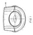
- FIG. 1is a top planar view of a Universal Serial Bus Docking Station with electronic modules
- FIG. 2is a front planar view of the Station of FIG. 1;
- FIG. 3is a left side planar view of the Station of FIG. 1, the right side view being a mirror image of the left side view;
- FIG. 4is a bottom planar view of the Station of FIG. 1;
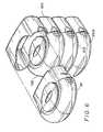
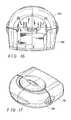
- FIG. 5is a perspective view of the Station of FIG. 1 with electronic modules
- FIG. 6is an exploded perspective view of the Station of FIG. 1 with one module separated from the docking station common portion;
- FIG. 7is a right side exploded perspective view of the Station of FIG. 1 with three modules separated from the common docking station portion;
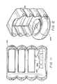
- FIG. 8is a rear exploded perspective view of the Station of FIG. 1 with three modules separated from the common docking station portion;
- FIG. 9is a front view of the Station of FIG. 1 with all modules removed;
- FIG. 10is a left side view of the Station of FIG. 9;
- FIG. 11is a rear view of the Station of FIG. 9;
- FIG. 12is a front perspective view of the station of FIG. 9;
- FIG. 13shows the station of FIG. 9 in exploded perspective view
- FIG. 14shows a circuit board of FIG. 13 in rear planar view
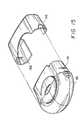
- FIG. 15is an explode perspective view of a module and a cover
- FIG. 16is a bottom planar view of the module and cover of FIG. 15;
- FIG. 17is a front perspective view of the module and cover of FIG. 15;
- FIG. 18is a left side view of the module and cover of FIG. 15;
- FIG. 19is a rear view of the module and cover of FIG. 15;
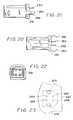
- FIG. 20is a side view of a connector mountable onto the circuit board of FIG. 14;
- FIG. 21is a top view of the connector of FIG. 20;
- FIG. 22is a front end view of the connector of FIG. 20.
- FIG. 23is a view of a portion of the circuit board of FIG. 14 adapted to receive the connector of FIG. 20 .
- the entirety of the Universal Serial Bus Specification Revision 1.1is incorporated herein by reference.
- a Universal Serial Bus Docking Stationis shown in FIGS. 1-13.
- the docking station 100includes a hub 200 and is populated with modules 101 , 102 , 103 .
- Each of modules 101 , 102 , 103can be either a USB hub or a USB function.
- a USB hub as used hereinis a USB device that provides additional connections to a USB.
- a USB functionis a USB device that provides capability to a host, such as for example, an ISDN connection, a digital microphone, or speakers. Where a module is a USB function, it in some instances provides the necessary interface between the actual item providing the functionality and the USB.
- three modules 101 , 102 , 103are shown inserted into docking station 100 , as is clearly evident from FIGS. 6-8, docking station 100 may be populated with 0, 1, 2 or 3 modules 101 , 102 , 103 .
- FIGS. 15-19illustrate a representative module 101 .
- module 101may be a USB hub or a USB function. More specifically, module 101 may be used in conjunction with docking station 100 , or it may be a stand alone unit. When used as a stand alone unit, a snap on sleeve 110 is used in conjunction with the module 101 .
- Module 101includes detents 151 on its right and left sides, only one detent being shown in FIG. 15 . Detents 151 will engage corresponding ribs 153 carried on housing 110 . Only one rib 153 is shown in FIG. 15 .
- module 101in the rear view of module 101 shown in FIG. 19, no particular connectors are shown.
- the connectors that would be carried by a module 101are determined by whether module 101 is a USB hub or a USB function. Such connectors may be carried in area 191 on the rear of module 101 .
- Each module 101 , 102 , 103additionally carries a connector 193 .
- the rear of sleeve 110is open to permit any connectors on the rear of module 101 to be accessible.
- FIGS. 7 and 8when module 101 is inserted into a docking station 100 , connector 193 receives mating connector 221 carried by docking station 100 .
- docking station 100includes hub 200 which comprises bottom casing 201 , upper casing 203 and its internal electronics carried on printed circuit board 205 .
- the electronic circuitrymay be any hub circuitry presently commercially utilized in USB hubs.
- Mounted on printed circuit board 205are a power connector 207 , a USB type B connector 209 (FIG. 11) and four USB type A connectors 211 (FIG. 11 ).
- USB type B connector 209is an upstream connector
- USB type A connectors 211are downstream connectors.
- docking station 100functions as a 7-port hub.
- a printed circuit board 220extends vertically upward from hub 200 .
- Printed circuit board 220carried three connectors 221 , 223 and 225 , which are disposed to engage corresponding connectors 193 (FIG. 19) on modules 101 , 102 , 103 , respectively, when they are inserted into docking station 100 .
- Printed circuit board 220includes conductor paths 297 (FIG. 14) from electrodes on connectors 221 , 223 , 225 to a connector block 235 which in turn mates with printed circuit board 205 .
- Connector 235provide a directional translation for the conductor paths from printed circuit board 205 to vertical printed circuit board 220 .
- each connector as shown in FIGS. 20-22includes shoulder portion 251 which is captured between printed circuit board 220 and support retainer 227 .
- each connector 221 , 223 , 225includes a pair of retaining clips 261 , 263 .
- Retaining clips 261 , 263are formed as extensions of the steel shell of the connector. Each extension 261 , 263 is bent outward away from the center of a connector and then inward.
- clips 261 and 263retain the connector in position until the terminals 253 , 255 , 257 , 259 are soldered.
- apertures 271 and 272are sized to engage the clips 261 and 263 respectively, whereas apertures 263 , 265 , 267 , 269 are adapted to receive terminals 253 , 255 , 257 , 259 , respectively.
- This connector arrangementpermits easy and fast assembly prior to soldering of the connectors to the printed circuit board.
- the conductor pattern on printed circuit board 220is a representative pattern; it should be evident to those skilled in the art that the conductor paths from each connector 221 , 223 , 225 extends to connector 235 where electrical connection is made to corresponding conductors on circuit board 205 .
- each module 101 , 102 , 103includes a connector which is positioned such that it will engage one of the connectors 221 , 223 , 225 when the corresponding module 101 , 102 , 103 is inserted into the docking station 100 .
- the docking station bodyis formed of plastic material as are the housings for modules 101 , 102 , 103 and the housing for hub 200 .
Landscapes
- Engineering & Computer Science (AREA)
- Microelectronics & Electronic Packaging (AREA)
- Details Of Connecting Devices For Male And Female Coupling (AREA)
Abstract
Description
Claims (25)
Priority Applications (2)
| Application Number | Priority Date | Filing Date | Title |
|---|---|---|---|
| US09/695,098US6560102B1 (en) | 2000-10-23 | 2000-10-23 | Universal serial bus docking station |
| US09/799,244US6462953B2 (en) | 1999-08-03 | 2001-03-05 | Universal serial bus module and system |
Applications Claiming Priority (1)
| Application Number | Priority Date | Filing Date | Title |
|---|---|---|---|
| US09/695,098US6560102B1 (en) | 2000-10-23 | 2000-10-23 | Universal serial bus docking station |
Related Parent Applications (1)
| Application Number | Title | Priority Date | Filing Date |
|---|---|---|---|
| US09/366,230DivisionUS6141221A (en) | 1999-08-03 | 1999-08-03 | Universal serial bus docking station |
Related Child Applications (1)
| Application Number | Title | Priority Date | Filing Date |
|---|---|---|---|
| US09/799,244DivisionUS6462953B2 (en) | 1999-08-03 | 2001-03-05 | Universal serial bus module and system |
Publications (1)
| Publication Number | Publication Date |
|---|---|
| US6560102B1true US6560102B1 (en) | 2003-05-06 |
Family
ID=24791545
Family Applications (2)
| Application Number | Title | Priority Date | Filing Date |
|---|---|---|---|
| US09/695,098Expired - Fee RelatedUS6560102B1 (en) | 1999-08-03 | 2000-10-23 | Universal serial bus docking station |
| US09/799,244Expired - LifetimeUS6462953B2 (en) | 1999-08-03 | 2001-03-05 | Universal serial bus module and system |
Family Applications After (1)
| Application Number | Title | Priority Date | Filing Date |
|---|---|---|---|
| US09/799,244Expired - LifetimeUS6462953B2 (en) | 1999-08-03 | 2001-03-05 | Universal serial bus module and system |
Country Status (1)
| Country | Link |
|---|---|
| US (2) | US6560102B1 (en) |
Cited By (20)
| Publication number | Priority date | Publication date | Assignee | Title |
|---|---|---|---|---|
| US20030141106A1 (en)* | 2002-01-30 | 2003-07-31 | Sievert Thomas Michael | Universal socket and component cartridge system |
| US6943296B2 (en) | 2003-12-03 | 2005-09-13 | Bellsouth Intellectual Property Corp. | USB wall plate |
| US20060224791A1 (en)* | 2005-03-31 | 2006-10-05 | Keppeler Karl E | Dual USB port device |
| USD560219S1 (en)* | 2006-08-04 | 2008-01-22 | Matsushita Electric Industrial Co., Ltd. | Contactless card reader/writer |
| US20080133815A1 (en)* | 2006-12-05 | 2008-06-05 | Kenneth Mori | Connectivity hub with a stationary base station and a removable second hub |
| USD578128S1 (en)* | 2006-07-05 | 2008-10-07 | Quanta Computer Inc. | Docking device |
| US8002587B2 (en) | 2009-09-25 | 2011-08-23 | Pucline, Llc | Ring-like electical power supplying structure for receiving the electrical power plugs of a plurality of electrical appliances and powering the same |
| US8002586B2 (en) | 2009-09-25 | 2011-08-23 | Pucline, Llc | Electrical power supplying device having a lower deck housing region for containing and concealing a plurality of electrical power adapters associated with a plurality of electrical appliances, and an upper deck housing region for supporting a ring-like power assembly having a central aperture and receiving the power plugs and/or power adapters of electrical appliances, while managing excess power cord length within a 3D volume passing through said central aperture |
| US8016611B2 (en) | 2009-09-25 | 2011-09-13 | Pucline Llc | Electrical power supplying device having a ring-like structure for receiving the power plugs and/or power adapters associated with a plurality of electrical appliances, and an integrated thermal management system |
| US8026633B2 (en) | 2009-09-25 | 2011-09-27 | Pucline, Llc | Wall-mountable electrical power supplying device for mounting to a wall surface about a standard wall-mounted power receptacle, using a mounting bracket arranged between the housing and wall surface and an electrical power supply plug integrated with the housing |
| US8159085B2 (en) | 2009-09-25 | 2012-04-17 | Pucline, Llc | Wall-mountable electrical power supplying device having a ring-like structure for receiving the power plugs and/or power adapters associated with a plurality of electrical appliances, and a housing containing and concealing the same during power supply operations |
| US8174147B2 (en) | 2009-09-25 | 2012-05-08 | Pucline, Llc | Electrical power supplying device having a ring-like power assembly for receiving electrical power plugs and/or power adapters associated with a plurality of electrical appliances, and an un-interrupted power supply (UPS) unit having a battery componenent mounted within a centrally-disposed structure passing through a central aperture in said ring-like power assembly |
| US8193658B2 (en) | 2009-09-25 | 2012-06-05 | Pucline, Llc | Electrical power supplying device having a ring-like subassembly for receiving the power plugs and/or power adapters associated with a plurality of electrical appliances, and managing excess power cord length therewithin in a concealed manner |
| US8217528B2 (en) | 2009-09-25 | 2012-07-10 | PUCline, Inc. | Electrical power supplying device having a ring-like subassembly for receiving the power plugs and/or power adapters associated with a plurality of electrical appliances, and a housing design for containing and concealing the power plug and adaptors during power supplying operations |
| US20120212898A1 (en)* | 2011-02-18 | 2012-08-23 | Hon Hai Precision Industry Co., Ltd. | Holding device for hard disk drive |
| US8378630B2 (en) | 2006-10-13 | 2013-02-19 | Nyko Technologies, Inc. | Video game controller charging system having a docking structure |
| US9184546B2 (en) | 2009-09-25 | 2015-11-10 | Pucline, Llc | Electrical power supplying device having a central power-hub assembly supplying electrical power to power plugs, adaptors and modules while concealed from view and managing excess power cord during power supplying operations |
| US9513682B2 (en) | 2013-07-03 | 2016-12-06 | Pucline, Llc | Transportable electrical power supplying device for storing and configuring excess power cord and sharing a multiplicity of AC and DC electrical power supplies in diverse user environments |
| US9912154B2 (en) | 2009-09-25 | 2018-03-06 | Pucline, Llc | Electrical power supplying device having a central power-receptacle assembly with a penisula-like housing structure supplying electrical power to power plugs, adaptors and modules while concealed from view during power supplying operations |
| US9927837B2 (en) | 2013-07-03 | 2018-03-27 | Pucline, Llc | Electrical power supplying system having an electrical power supplying docking station with a multi-function module for use in diverse environments |
Families Citing this family (30)
| Publication number | Priority date | Publication date | Assignee | Title |
|---|---|---|---|---|
| WO2001042937A1 (en)* | 1999-12-06 | 2001-06-14 | Henry Milan | Modular stackable component system including universal serial bus hub |
| US6726509B2 (en) | 1999-12-06 | 2004-04-27 | Henry Milan | Stackable power supply system |
| TW476902B (en)* | 2000-05-19 | 2002-02-21 | Acer Inc | Universal serial bus hub |
| US7028126B1 (en)* | 2000-09-21 | 2006-04-11 | Ping Liang | Universal serial bus for mobile devices having expansion modules |
| US6736658B2 (en)* | 2000-12-05 | 2004-05-18 | Henry Milan | Power supply interconnecting device |
| DE10061854C2 (en)* | 2000-12-12 | 2002-11-14 | Testo Gmbh & Co Kg | Module for measurement purposes |
| US6570756B2 (en)* | 2001-10-10 | 2003-05-27 | Dell Products L.P. | Personal computer system housing and security system |
| DE10211438A1 (en)* | 2002-03-07 | 2003-10-09 | Koop Peter | Housing system for accommodating slide-in devices |
| US6801476B2 (en)* | 2002-04-15 | 2004-10-05 | Daniel A. Gilmour | Wrist-worn phone and body-worn data storage device |
| US6983341B1 (en)* | 2002-05-21 | 2006-01-03 | Adaptec, Inc. | Modular peripheral device hub |
| USD494932S1 (en) | 2002-05-23 | 2004-08-24 | Henry Milan | Daisy chain connector for stackable hubs |
| JP4026410B2 (en)* | 2002-05-24 | 2007-12-26 | 三菱自動車工業株式会社 | Valve operating device for internal combustion engine |
| US7322863B2 (en)* | 2003-03-27 | 2008-01-29 | Robert Rapp | Robust modular electronic device without direct electrical connections for inter-module communication or control |
| US7094074B2 (en)* | 2003-09-11 | 2006-08-22 | Super Talent Electronics, Inc. | Manufacturing methods for ultra-slim USB flash-memory card with supporting dividers or underside ribs |
| US20050070138A1 (en)* | 2003-09-11 | 2005-03-31 | Super Talent Electronics Inc. | Slim USB Plug and Flash-Memory Card with Supporting Underside Ribs Engaging Socket Springs |
| US8102657B2 (en) | 2003-12-02 | 2012-01-24 | Super Talent Electronics, Inc. | Single shot molding method for COB USB/EUSB devices with contact pad ribs |
| US8998620B2 (en)* | 2003-12-02 | 2015-04-07 | Super Talent Technology, Corp. | Molding method for COB-EUSB devices and metal housing package |
| TWM251205U (en)* | 2003-12-17 | 2004-11-21 | Icp Electronics Inc | Integrated USB device |
| US20050172062A1 (en)* | 2003-12-18 | 2005-08-04 | Brad Adams | Electronic and mechanical system for use with computers |
| US20050240709A1 (en)* | 2004-04-22 | 2005-10-27 | Shaver Charles N | Expansion card |
| US20050240702A1 (en)* | 2004-04-22 | 2005-10-27 | Kunkel Larry W | Detecting expansion card connector mating status |
| US7927313B2 (en) | 2004-05-27 | 2011-04-19 | Baxter International Inc. | Medical device configuration based on recognition of identification information |
| US8961461B2 (en) | 2004-05-27 | 2015-02-24 | Baxter International Inc. | Multi-state alarm system for a medical pump |
| CN2821899Y (en)* | 2005-07-09 | 2006-09-27 | 鸿富锦精密工业(深圳)有限公司 | Combined general series bus connector |
| US20070167081A1 (en)* | 2006-01-17 | 2007-07-19 | David Edelson | Modular multi configuration standardized bus computer system |
| US7511967B2 (en)* | 2007-02-20 | 2009-03-31 | United Technologies Corporation | Avionics enclosure |
| TWI389396B (en)* | 2009-11-18 | 2013-03-11 | Transcend Information Inc | Usb connector |
| US9048666B2 (en)* | 2013-07-09 | 2015-06-02 | Chen-Source Inc. | USB charging circuit |
| KR102367586B1 (en)* | 2015-04-10 | 2022-02-28 | 삼성전자주식회사 | Electronic device |
| EP3282519B1 (en)* | 2016-08-08 | 2021-05-19 | Murrelektronik GmbH | Modular distribution for electrical lines |
Citations (26)
| Publication number | Priority date | Publication date | Assignee | Title |
|---|---|---|---|---|
| US4119359A (en) | 1977-08-25 | 1978-10-10 | Stanford Applied Engineering, Inc. | Phono-socket assembly and method |
| US4845589A (en) | 1987-05-04 | 1989-07-04 | Amp Incorporated | Bus bar connector assembly |
| US5030128A (en)* | 1989-03-06 | 1991-07-09 | Dynabook Technologies Corporation | Docking module |
| US5333097A (en) | 1992-06-18 | 1994-07-26 | Digital Equipment Corporation | Disk drive holder and interconnection system |
| US5336102A (en)* | 1993-06-07 | 1994-08-09 | Ford Motor Company | Connector interface seal |
| US5358420A (en)* | 1993-06-07 | 1994-10-25 | Ford Motor Company | Pressure relief for an electrical connector |
| US5381315A (en) | 1993-03-09 | 1995-01-10 | Fujitsu Limited | Shelf assembly in electronic switching system |
| US5483419A (en) | 1991-09-24 | 1996-01-09 | Teac Corporation | Hot-swappable multi-cartridge docking module |
| US5498174A (en) | 1994-10-18 | 1996-03-12 | The Whitaker Corporation | Electrical connector with spring leg retention feature |
| US5515239A (en) | 1994-02-18 | 1996-05-07 | Quantum Corporation | Stackable modular storage tower |
| US5586002A (en) | 1992-06-24 | 1996-12-17 | John Notarianni | Protective case and interface housing containing computer devices and the like |
| US5591048A (en) | 1994-05-10 | 1997-01-07 | Berg Technology, Inc. | Multiple fish hook hold-downs |
| US5604662A (en) | 1992-08-20 | 1997-02-18 | Streamlogic Corporation | Expandable modular data storage system |
| US5621890A (en) | 1991-06-21 | 1997-04-15 | John Notarianni | Method and apparatus for transferring data between a host device and a plurality of portable computers |
| US5673172A (en) | 1996-01-05 | 1997-09-30 | Compaq Computer Corporation | Apparatus for electromagnetic interference and electrostatic discharge shielding of hot plug-connected hard disk drives |
| US5700159A (en) | 1995-03-30 | 1997-12-23 | Vossloh-Schwabe Gmbh | Electrical connection element |
| US5706179A (en) | 1996-02-07 | 1998-01-06 | Palatov; Dennis | Computer housing and expansion card format for consumer electronics devices |
| US5726922A (en) | 1994-01-03 | 1998-03-10 | International Business Machines Corp. | Assembly for removably connecting data storage devices |
| US5737189A (en) | 1994-01-10 | 1998-04-07 | Artecon | High performance mass storage subsystem |
| US5777845A (en) | 1995-05-24 | 1998-07-07 | Seagate Technology, Inc. | High density redundant array of independent disks in a chassis having a door with shock absorbers held against the disks when the door is closed |
| USRE35915E (en) | 1992-09-24 | 1998-10-06 | Compaq Computer Corporation | Apparatus for removably supporting a plurality of hot plug-connected hard disk drives |
| US5835353A (en) | 1995-12-08 | 1998-11-10 | Northern Telecom Limited | Modular assembly for supporting an electronic circuit package |
| US5896273A (en) | 1996-12-31 | 1999-04-20 | Compaq Computer Corp. | Modular computer chassis interchangeable between stand alone and rack mounted states |
| US5938473A (en) | 1996-07-22 | 1999-08-17 | Mitsumi Electric Co., Ltd. | Electrical connector with vertical lift prevention mechanism |
| US6018456A (en) | 1996-05-31 | 2000-01-25 | Cmd Technology, Inc. | Enclosure for removable computer peripheral equipment |
| US6141221A (en)* | 1999-08-03 | 2000-10-31 | Belkin Components | Universal serial bus docking station |
Family Cites Families (25)
| Publication number | Priority date | Publication date | Assignee | Title |
|---|---|---|---|---|
| US4401351A (en)* | 1981-09-28 | 1983-08-30 | Advant Corporation | Expandable card cage |
| US4558914A (en)* | 1982-09-23 | 1985-12-17 | Gould Inc. | Readily expandable input/output construction for programmable controller |
| US4501460A (en)* | 1983-05-09 | 1985-02-26 | Convergent Technologies, Inc. | Modular housing for computer system |
| FR2580136B1 (en)* | 1985-04-05 | 1988-10-14 | Radiotechnique Compelec | |
| US5440181A (en)* | 1994-01-31 | 1995-08-08 | Motorola, Inc. | Configuration circuit for configuring a multi-board system automatically |
| US5822184A (en)* | 1994-07-28 | 1998-10-13 | Rabinovitz; Josef | Modular disk drive assembly operatively mountable in industry standard expansion bays of personal desktop computers |
| USD366455S (en)* | 1994-11-09 | 1996-01-23 | D-Link Corporation | Portable hub |
| US5825618A (en)* | 1995-10-26 | 1998-10-20 | The Whitaker Corporation | Hub for a communications network |
| US5645434A (en)* | 1995-12-01 | 1997-07-08 | Asante Technologies, Inc. | Connector element and component arrangement for a stackable communications network hub |
| US6076142A (en)* | 1996-03-15 | 2000-06-13 | Ampex Corporation | User configurable raid system with multiple data bus segments and removable electrical bridges |
| US5871368A (en)* | 1996-11-19 | 1999-02-16 | Intel Corporation | Bus connector |
| USD408012S (en)* | 1997-06-27 | 1999-04-13 | The Whitaker Corporation | Hub |
| US6073188A (en)* | 1997-07-25 | 2000-06-06 | Compaq Computer Corporation | Electronic switchbox for selection and sharing of internal peripheral devices among different computers, the internal peripheral devices located in slots of a chassis |
| TW347105U (en)* | 1997-09-19 | 1998-12-01 | Mitac Int Corp | Integrated-type computer |
| AU701144B3 (en)* | 1998-06-29 | 1999-01-21 | Compal Electronics, Inc. | Stand having a housing adapted for supporting a liquid crystal display panel on a base, and a universal serial bus hub module mounted detachably on the housing |
| US6052278A (en)* | 1998-11-13 | 2000-04-18 | Hewlett-Packard Company | Data storage module and enclosure system |
| JP2000163168A (en)* | 1998-11-24 | 2000-06-16 | Nanao Corp | Serial bus hub unit and image display device equipped with the same and card type peripheral equipment used for the same |
| USD425866S (en)* | 1998-12-15 | 2000-05-30 | Accton Technology Corporation | Usb hub |
| JP2000231969A (en)* | 1999-02-12 | 2000-08-22 | Mitsumi Electric Co Ltd | Usb hub |
| JP2000311032A (en)* | 1999-02-26 | 2000-11-07 | Haatec:Kk | Interior housing furniture for personal computer equipment |
| USD421962S (en)* | 1999-04-21 | 2000-03-28 | Acco Brands, Inc. | USB hub |
| GB2350032B (en)* | 1999-05-12 | 2001-04-11 | 3Com Corp | Method and apparatus for configuration of stackable units in packet-based communication systems |
| JP2001102136A (en)* | 1999-07-27 | 2001-04-13 | Mitsumi Electric Co Ltd | Connector of an electronic apparatus, usb connector device, and an electronic apparatus having a connection device |
| USD436109S1 (en)* | 1999-08-03 | 2001-01-09 | Belkin Components | Universal serial bus module |
| US6147859A (en)* | 1999-08-18 | 2000-11-14 | Ops, Inc. | Modular external peripheral housing |
- 2000
- 2000-10-23USUS09/695,098patent/US6560102B1/ennot_activeExpired - Fee Related
- 2001
- 2001-03-05USUS09/799,244patent/US6462953B2/ennot_activeExpired - Lifetime
Patent Citations (26)
| Publication number | Priority date | Publication date | Assignee | Title |
|---|---|---|---|---|
| US4119359A (en) | 1977-08-25 | 1978-10-10 | Stanford Applied Engineering, Inc. | Phono-socket assembly and method |
| US4845589A (en) | 1987-05-04 | 1989-07-04 | Amp Incorporated | Bus bar connector assembly |
| US5030128A (en)* | 1989-03-06 | 1991-07-09 | Dynabook Technologies Corporation | Docking module |
| US5621890A (en) | 1991-06-21 | 1997-04-15 | John Notarianni | Method and apparatus for transferring data between a host device and a plurality of portable computers |
| US5483419A (en) | 1991-09-24 | 1996-01-09 | Teac Corporation | Hot-swappable multi-cartridge docking module |
| US5333097A (en) | 1992-06-18 | 1994-07-26 | Digital Equipment Corporation | Disk drive holder and interconnection system |
| US5586002A (en) | 1992-06-24 | 1996-12-17 | John Notarianni | Protective case and interface housing containing computer devices and the like |
| US5604662A (en) | 1992-08-20 | 1997-02-18 | Streamlogic Corporation | Expandable modular data storage system |
| USRE35915E (en) | 1992-09-24 | 1998-10-06 | Compaq Computer Corporation | Apparatus for removably supporting a plurality of hot plug-connected hard disk drives |
| US5381315A (en) | 1993-03-09 | 1995-01-10 | Fujitsu Limited | Shelf assembly in electronic switching system |
| US5336102A (en)* | 1993-06-07 | 1994-08-09 | Ford Motor Company | Connector interface seal |
| US5358420A (en)* | 1993-06-07 | 1994-10-25 | Ford Motor Company | Pressure relief for an electrical connector |
| US5726922A (en) | 1994-01-03 | 1998-03-10 | International Business Machines Corp. | Assembly for removably connecting data storage devices |
| US5737189A (en) | 1994-01-10 | 1998-04-07 | Artecon | High performance mass storage subsystem |
| US5515239A (en) | 1994-02-18 | 1996-05-07 | Quantum Corporation | Stackable modular storage tower |
| US5591048A (en) | 1994-05-10 | 1997-01-07 | Berg Technology, Inc. | Multiple fish hook hold-downs |
| US5498174A (en) | 1994-10-18 | 1996-03-12 | The Whitaker Corporation | Electrical connector with spring leg retention feature |
| US5700159A (en) | 1995-03-30 | 1997-12-23 | Vossloh-Schwabe Gmbh | Electrical connection element |
| US5777845A (en) | 1995-05-24 | 1998-07-07 | Seagate Technology, Inc. | High density redundant array of independent disks in a chassis having a door with shock absorbers held against the disks when the door is closed |
| US5835353A (en) | 1995-12-08 | 1998-11-10 | Northern Telecom Limited | Modular assembly for supporting an electronic circuit package |
| US5673172A (en) | 1996-01-05 | 1997-09-30 | Compaq Computer Corporation | Apparatus for electromagnetic interference and electrostatic discharge shielding of hot plug-connected hard disk drives |
| US5706179A (en) | 1996-02-07 | 1998-01-06 | Palatov; Dennis | Computer housing and expansion card format for consumer electronics devices |
| US6018456A (en) | 1996-05-31 | 2000-01-25 | Cmd Technology, Inc. | Enclosure for removable computer peripheral equipment |
| US5938473A (en) | 1996-07-22 | 1999-08-17 | Mitsumi Electric Co., Ltd. | Electrical connector with vertical lift prevention mechanism |
| US5896273A (en) | 1996-12-31 | 1999-04-20 | Compaq Computer Corp. | Modular computer chassis interchangeable between stand alone and rack mounted states |
| US6141221A (en)* | 1999-08-03 | 2000-10-31 | Belkin Components | Universal serial bus docking station |
Cited By (28)
| Publication number | Priority date | Publication date | Assignee | Title |
|---|---|---|---|---|
| US20030141106A1 (en)* | 2002-01-30 | 2003-07-31 | Sievert Thomas Michael | Universal socket and component cartridge system |
| US6943296B2 (en) | 2003-12-03 | 2005-09-13 | Bellsouth Intellectual Property Corp. | USB wall plate |
| US20060224791A1 (en)* | 2005-03-31 | 2006-10-05 | Keppeler Karl E | Dual USB port device |
| USD578128S1 (en)* | 2006-07-05 | 2008-10-07 | Quanta Computer Inc. | Docking device |
| USD560219S1 (en)* | 2006-08-04 | 2008-01-22 | Matsushita Electric Industrial Co., Ltd. | Contactless card reader/writer |
| US9705344B2 (en) | 2006-10-13 | 2017-07-11 | Nyko Technologies, Inc. | Video game controller charging system having a docking structure |
| US9174121B2 (en) | 2006-10-13 | 2015-11-03 | Nyko Technologies, Inc. | Video game controller charging system having a docking structure |
| US8633675B2 (en) | 2006-10-13 | 2014-01-21 | Nyko Technologies, Inc. | Video game controller charging system having a docking structure |
| US8536832B2 (en) | 2006-10-13 | 2013-09-17 | Nyko Technologies, Inc. | Video game controller charging system having a docking structure |
| US8378630B2 (en) | 2006-10-13 | 2013-02-19 | Nyko Technologies, Inc. | Video game controller charging system having a docking structure |
| US20080133815A1 (en)* | 2006-12-05 | 2008-06-05 | Kenneth Mori | Connectivity hub with a stationary base station and a removable second hub |
| US7899970B2 (en) | 2006-12-05 | 2011-03-01 | Belkin International, Inc. | Connectivity hub with a stationary base station and a removable second hub |
| US8217528B2 (en) | 2009-09-25 | 2012-07-10 | PUCline, Inc. | Electrical power supplying device having a ring-like subassembly for receiving the power plugs and/or power adapters associated with a plurality of electrical appliances, and a housing design for containing and concealing the power plug and adaptors during power supplying operations |
| US8002587B2 (en) | 2009-09-25 | 2011-08-23 | Pucline, Llc | Ring-like electical power supplying structure for receiving the electrical power plugs of a plurality of electrical appliances and powering the same |
| US8174147B2 (en) | 2009-09-25 | 2012-05-08 | Pucline, Llc | Electrical power supplying device having a ring-like power assembly for receiving electrical power plugs and/or power adapters associated with a plurality of electrical appliances, and an un-interrupted power supply (UPS) unit having a battery componenent mounted within a centrally-disposed structure passing through a central aperture in said ring-like power assembly |
| US9912154B2 (en) | 2009-09-25 | 2018-03-06 | Pucline, Llc | Electrical power supplying device having a central power-receptacle assembly with a penisula-like housing structure supplying electrical power to power plugs, adaptors and modules while concealed from view during power supplying operations |
| US8193658B2 (en) | 2009-09-25 | 2012-06-05 | Pucline, Llc | Electrical power supplying device having a ring-like subassembly for receiving the power plugs and/or power adapters associated with a plurality of electrical appliances, and managing excess power cord length therewithin in a concealed manner |
| US8159085B2 (en) | 2009-09-25 | 2012-04-17 | Pucline, Llc | Wall-mountable electrical power supplying device having a ring-like structure for receiving the power plugs and/or power adapters associated with a plurality of electrical appliances, and a housing containing and concealing the same during power supply operations |
| US8026633B2 (en) | 2009-09-25 | 2011-09-27 | Pucline, Llc | Wall-mountable electrical power supplying device for mounting to a wall surface about a standard wall-mounted power receptacle, using a mounting bracket arranged between the housing and wall surface and an electrical power supply plug integrated with the housing |
| US8016611B2 (en) | 2009-09-25 | 2011-09-13 | Pucline Llc | Electrical power supplying device having a ring-like structure for receiving the power plugs and/or power adapters associated with a plurality of electrical appliances, and an integrated thermal management system |
| US8002586B2 (en) | 2009-09-25 | 2011-08-23 | Pucline, Llc | Electrical power supplying device having a lower deck housing region for containing and concealing a plurality of electrical power adapters associated with a plurality of electrical appliances, and an upper deck housing region for supporting a ring-like power assembly having a central aperture and receiving the power plugs and/or power adapters of electrical appliances, while managing excess power cord length within a 3D volume passing through said central aperture |
| US9184546B2 (en) | 2009-09-25 | 2015-11-10 | Pucline, Llc | Electrical power supplying device having a central power-hub assembly supplying electrical power to power plugs, adaptors and modules while concealed from view and managing excess power cord during power supplying operations |
| US8351197B2 (en)* | 2011-02-18 | 2013-01-08 | Hon Hai Precision Industry Co., Ltd. | Holding device for hard disk drive |
| US20120212898A1 (en)* | 2011-02-18 | 2012-08-23 | Hon Hai Precision Industry Co., Ltd. | Holding device for hard disk drive |
| US9513682B2 (en) | 2013-07-03 | 2016-12-06 | Pucline, Llc | Transportable electrical power supplying device for storing and configuring excess power cord and sharing a multiplicity of AC and DC electrical power supplies in diverse user environments |
| US9927837B2 (en) | 2013-07-03 | 2018-03-27 | Pucline, Llc | Electrical power supplying system having an electrical power supplying docking station with a multi-function module for use in diverse environments |
| US11150697B2 (en) | 2013-07-03 | 2021-10-19 | Pucline Llc | Multi-function electrical power supplying station with dockable station supporting emergency lighting, portable lighting, and consumer device battery recharging modes of operation |
| US11614784B2 (en) | 2013-07-03 | 2023-03-28 | Pucline, Llc | Electrical power supplying and cord management station with dockable module supporting multiple modes of operation |
Also Published As
| Publication number | Publication date |
|---|---|
| US20010021101A1 (en) | 2001-09-13 |
| US6462953B2 (en) | 2002-10-08 |
Similar Documents
| Publication | Publication Date | Title |
|---|---|---|
| US6560102B1 (en) | Universal serial bus docking station | |
| US6141221A (en) | Universal serial bus docking station | |
| US7670191B2 (en) | Extension/expansion to universal serial bus connector | |
| US6215656B1 (en) | Method and apparatus for factory or user configurable external connectors | |
| US6948983B1 (en) | Slim USB male connector with anti-disorientation design | |
| US7654871B2 (en) | Electrical connector with additional mating port | |
| US7682200B2 (en) | Electrical connector with improved contacts and transition module | |
| CN101364692B (en) | Electric connector for socket | |
| US7744382B2 (en) | Electrical connector with improved contact arrangement | |
| CN102544803B (en) | Cable Connector Assembly | |
| US20100055980A1 (en) | Extension to version 2.0 universal serial bus connector with additional contacts | |
| US6137679A (en) | Multi-bus mobile hard disk drive rack | |
| JP2004281404A (en) | Electric coupler | |
| US6206724B1 (en) | Combined connector for ethernet and modem cables | |
| US20030186582A1 (en) | Worksurface power module with built in USB hub | |
| US8976510B2 (en) | Cable assembly and electronic device | |
| US6824422B2 (en) | Expandable connecting hub assembly | |
| US20020001998A1 (en) | Adapter for connecting rj-45 port and rj-11 port | |
| US20090117777A1 (en) | Keyboard, video and mouse (kvm) switch | |
| US20070072491A1 (en) | Integrated signal connecting port | |
| US6141212A (en) | Method and apparatus for connecting peripherals having various size plugs and functions | |
| US6896527B1 (en) | Slim USB male connector with system grounding | |
| US6662259B1 (en) | Modularized universal serial bus hub | |
| TWM267663U (en) | Computer interconnect system | |
| KR200399441Y1 (en) | Multi-USB gender |
Legal Events
| Date | Code | Title | Description |
|---|---|---|---|
| AS | Assignment | Owner name:BELKIN CORPORATION, CALIFORNIA Free format text:CHANGE OF NAME;ASSIGNOR:BELKIN COMPONENTS;REEL/FRAME:013089/0031 Effective date:20020620 | |
| AS | Assignment | Owner name:WELLS FARGO BANK, NATIONAL ASSOCIATION, AS THE ADM Free format text:SECURITY AGREEMENT;ASSIGNOR:BELKIN CORPORATION;REEL/FRAME:013305/0942 Effective date:20020912 | |
| FPAY | Fee payment | Year of fee payment:4 | |
| FPAY | Fee payment | Year of fee payment:8 | |
| SULP | Surcharge for late payment | Year of fee payment:7 | |
| AS | Assignment | Owner name:BELKIN INTERNATIONAL, INC. (FORMERLY KNOWN AS BELK Free format text:RELEASE BY SECURED PARTY;ASSIGNOR:WELLS FARGO BANK, NATIONAL ASSOCIATION, AS ADMINISTRATIVE AGENT, L/C ISSUER AND SWING LINE LENDER;REEL/FRAME:027008/0824 Effective date:20110930 Owner name:BELKIN, INC. (FORMERLY KNOWN AS BELKIN LOGISTICS, Free format text:RELEASE BY SECURED PARTY;ASSIGNOR:WELLS FARGO BANK, NATIONAL ASSOCIATION, AS ADMINISTRATIVE AGENT, L/C ISSUER AND SWING LINE LENDER;REEL/FRAME:027008/0824 Effective date:20110930 | |
| AS | Assignment | Owner name:WELLS FARGO CAPITAL FINANCE, LLC, AS AGENT, CALIFO Free format text:PATENT SECURITY AGREEMENT;ASSIGNOR:BELKIN INTERNATIONAL, INC;REEL/FRAME:027844/0525 Effective date:20120306 | |
| REMI | Maintenance fee reminder mailed | ||
| LAPS | Lapse for failure to pay maintenance fees | ||
| STCH | Information on status: patent discontinuation | Free format text:PATENT EXPIRED DUE TO NONPAYMENT OF MAINTENANCE FEES UNDER 37 CFR 1.362 | |
| FP | Lapsed due to failure to pay maintenance fee | Effective date:20150506 |