US6559882B1 - Domestic appliance - Google Patents
Domestic applianceDownload PDFInfo
- Publication number
- US6559882B1 US6559882B1US09/388,811US38881199AUS6559882B1US 6559882 B1US6559882 B1US 6559882B1US 38881199 AUS38881199 AUS 38881199AUS 6559882 B1US6559882 B1US 6559882B1
- Authority
- US
- United States
- Prior art keywords
- appliance
- communications module
- user
- communications
- display
- Prior art date
- Legal status (The legal status is an assumption and is not a legal conclusion. Google has not performed a legal analysis and makes no representation as to the accuracy of the status listed.)
- Expired - Lifetime
Links
Images


Classifications
- H—ELECTRICITY
- H05—ELECTRIC TECHNIQUES NOT OTHERWISE PROVIDED FOR
- H05B—ELECTRIC HEATING; ELECTRIC LIGHT SOURCES NOT OTHERWISE PROVIDED FOR; CIRCUIT ARRANGEMENTS FOR ELECTRIC LIGHT SOURCES, IN GENERAL
- H05B6/00—Heating by electric, magnetic or electromagnetic fields
- H05B6/64—Heating using microwaves
- H05B6/6435—Aspects relating to the user interface of the microwave heating apparatus
Definitions
- the present inventionrelates to communications, and contemplates easy-to-use computing devices deemed necessary to drive the next generation of computing.
- Particular aspects of the inventionrelate to communications in the domestic environment, involving a system arranged to manage data and to communicate data between the home and selected remote facilities.
- Telephone bankingis already very popular and many banks now offer customers the option of on-line home banking over the Internet.
- Large supermarkets and department storesoffer home delivery services, where a customer places an order for specific goods such as groceries by telephone or over the Internet and the ordered goods are subsequently delivered to the customer's home.
- Paymentis generally effected by providing credit/debit or store card details when placing the order.
- PCpersonal computer
- the Applicanthas devised the concept of an Internet- and TV-enabled domestic appliance, preferably in the form of a microwave oven.
- the conceptarose from several factors. One is the development of new relationship technologies, relating to how the appliance communicates with consumers via the Internet. Another is the idea of being there—a permanent presence, always on. The concept also depends upon sensitivity to the context and usefulness of the appliance with respect to its normal use within the home, and understanding and predicting the consumer's needs and desires, to offer suitable facilities through the appliance. In sum, the concept is intended to capture a significant proportion of the many currently-offline consumers by providing a familiar appliance in a familiar location, that has attractive functionality such as free TV and a simple user interface.
- the inventioncontemplates a technically-sophisticated (albeit easy to use) communications module whose manufacture will require facilities that may not be available to appliance manufacturers.
- appliancescome in myriad shapes and sizes. It would be a major barrier to propagation of the technology if appliance manufacturers had to invest in making communications modules or in totally redesigning their appliances to accept such modules. It would similarly be a barrier if the communications module had in all cases to be adapted to suit the appliance.
- a domestic applianceis provided with mounting hardware, a discrete communications module connectable to a communications network, and an adaptor including means for attachment to the mounting hardware on the appliance and means for mounting the communications module to the appliance via the adaptor.
- the communications moduleis preferably received in a recess in the adaptor, the adaptor suitably framing the mounted communications module received in the recess.
- bias meansmay be provided to urge the communications module out of the recess.
- latch means acting against the bias meansmay be provided to hold the communications module releasably in the recess.
- Adjustment for viewing of a display on the communications moduleis catered for by movably mounting the communications module with respect to the adaptor.
- the adaptor and the communications moduleare connected by mounting hardware that permits the communications module to adopt any of a plurality of discrete positions with respect to the adaptor.
- the appliancehas a door and that the mounting hardware, the adaptor and the communications module are part of the door of the appliance.
- the applianceis most preferably a microwave oven.
- the communications moduleis connectable to the communications network via a flying lead connectable to the appliance, the flying lead preferably connecting to an external terminal on the appliance.
- the flying leadmay include a port for data communication between the communications module and the appliance.
- This aspect of the inventionextends to a method of assembling a domestic appliance and a standard communications module, the method comprising providing one of a plurality of different domestic appliances having mounting hardware, fitting to the mounting hardware of that appliance an appropriate one of a plurality of different adaptors each having a standard mounting for a communications module and means cooperable with the mounting hardware, and mounting to that adaptor a standard communications module.
- the inventioncontemplates a domestic appliance having a primary domestic function but being adapted for the secondary function of interaction with a communications network, the appliance including a user interface operable by direct contact with the appliance and a remote control facility operable by a remote control handset, wherein activating or deactivating the primary function of the appliance is reserved for the user interface and the remote control facility is incapable of activating or deactivating the primary function.
- the primary function of the appliancewill be cooking, defrosting or freezing.
- the applianceis preferably a microwave oven in which case the primary function is cooking or defrosting.
- a conveniently integrated user interfacecan be constructed if the primary function of the appliance is operable via the communications network. It is envisaged that the remote control facility is capable of controlling the secondary function and optionally also part of the primary function of the appliance.
- Advertising revenuesare an important enabling factor in propagating the technology, bearing in mind that the communications module is but one element of a communications system also involving a broadband online connection and a broadband portal, all of which will be costly to develop, use or run. Consumers are traditionally unwilling to pay extra for general Internet services, especially if they are already paying a subscription to secure access to the Internet.
- open accessgives the user access to all sites on the World Wide Web (subject to e.g. filtering for adult content) whereas closed access enables access to only selected sites, which may be specially adapted to users of the appliance.
- Closed accesshas superficial advantages for the service provider. These advantages are a captive body of customers, T-tax revenues from all on-line transactions that those customers perform through the limited portals that are available to them, and increased advertising rates at those portals because the portals will have a high level of visits by each active user. Open access is less directly profitable in this respect because customers are free to migrate to other sites. Nevertheless, open access is more appealing to the customer and so it is thought that any short-term reduction in revenues per customer by opting for open access will be more than compensated by a longer-term increase in the overall number of customers. A virtuous cycle results, with increased customer numbers bringing in greater advertising and T-tax revenues which, reinvested, improve content and attract more customers.
- the most important driver in any advertising revenue streamis ‘reach’, which is the number of active customers.
- the inventiontherefore contemplates the provision of open access but that customers are enticed to stay with the appropriate service provider and discouraged to leave. Aspects of the invention reside in these enticements and discouragements, and more generally in the design of the portal itself.
- the inventioncontemplates an Internet redirection system for enabling an Internet service provider or ISP to control open Internet access by redirecting the user to an alternative version of a web site addressed by a user, the alternative version being specific to the service provider, wherein the system comprises a redirection table for storing a list of web sites for which alternative versions specific to the service provider exist, look-up means for consulting the redirection table when a user addresses a desired web site, and redirection means for redirecting the user to the alternative version of the addressed web site when such an alternative exists in the redirection table.
- the redirection tablemay be stored locally on the user's Internet-browsing apparatus, in which case the system preferably includes update means for updating the redirection table by periodic download from the Internet service provider.
- the update meansmay be responsive to activation of the browsing apparatus, so as to update the redirection table upon powering up the apparatus.
- This aspect of the inventionmay also be expressed as an Internet redirection method for enabling an Internet service provider to control open Internet access by redirecting the user to an alternative version of a web site addressed by a user, the alternative version being specific to the service provider, wherein the method comprises maintaining a redirection table storing a list of web sites for which alternative versions specific to the service provider exist, consulting the redirection table when a user addresses a desired web site, and redirecting the user to the alternative version of the addressed web site when such an alternative exists in the redirection table.
- the inventionprovides an Internet access system comprising an Internet-browsing apparatus operable by a user and being connected to the Internet, wherein the browsing apparatus is configured to open, upon activation, a web page that is not selectable by the user.
- the browsing apparatuspreferably includes TV functionality.
- control of the TV functionalityis conveniently effected via the web page.
- the browsing apparatusmay also control a domestic appliance in the manner aforesaid and again, control of the appliance may be effected via the web page.
- the inventiontherefore extends to a method of controlling TV functionality in Internet-browsing apparatus connected to the Internet, comprising using the Internet-browsing apparatus to retrieve a web page and using that web page to control the TV functionality.
- the inventionencompasses a method of controlling a domestic appliance, comprising using an Internet-browsing apparatus to retrieve a web page and using that web page to control the appliance.
- the web pagecan be downloaded from the Internet or retrieved from local storage in the Internet-browsing apparatus.
- Either of these methodscan further comprise delivering advertising or information images to the web page used by the Internet-browsing apparatus in controlling the TV functionality or the appliance.
- the usercan be exposed to advertising via the web page used for control, for example by targeted banner advertising to which the user can respond by ‘clicking-through’, or by a sponsored frame of adverts around a TV window embedded within the web page.
- Meanscan be provided for varying the advertising or information images in accordance with the time of day, the weather, or stored user characteristics including predetermined preferences and interests, demographic standing, and recent buying or browsing patterns.
- an aspect of the inventionrelates to an Internet portal providing content and/or advertising sections under control of a content delivery engine and/or an advertising engine, wherein the portal is associated with a user profile database that stores perceived user preferences and provides outputs to the content delivery engine and/or the advertising engine to target content and/or advertising according to the perceived preferences.
- the user profile databaseis preferably adaptive, taking inputs representing user behavior to reflect the user's buying and browsing habits.
- the user profile databasecan take input from an advertising engine that gathers and forwards data on the user's response to adverts at the portal.
- the user profile databasecan also take input from a commerce engine that gathers and forwards data on purchases made by the user via the portal.
- a cooking or defrosting applianceincluding a heating region and a camera for obtaining images of food cooking or defrosting within the heating region, wherein the camera outputs video signals to a processor that drives a display means associated with the appliance and/or controls the cooking or defrosting operation of the appliance.
- the display meansis conveniently situated on the appliance to show an easily-viewable image of the food obtained by the camera.
- the camerais sensitive to infra-red radiation and outputs video signals representative of the heat of the food.
- the processorcan therefore convert infra-red information received from the camera into visible information to create a display on the display means representative of the infra-red information.
- a displayis preferably color-coded in accordance with the local temperature of the food.
- the processormay compare food temperature represented by the infra red image with a stored model and, depending upon variance with the model, the processor can send control outputs to the appliance to vary heating power and/or exposure time to heat.
- the displayalso performs Internet, e-commerce, or home networking functions and so the display is preferably switchable to display the food in the heating region when the appliance is in use cooking or defrosting. Conveniently, the display switches automatically at the start and end of a cooking or defrosting operation.
- the camerais preferably fixed and food is moved in relation to the camera during a cooking or defrosting operation, for example being on a turntable.
- This aspect of the inventionembraces a method of cooking or defrosting, comprising obtaining infra-red images of cooking or defrosting food from a camera that outputs video signals to a processor, and processing or displaying the information from the camera to control the cooking or defrosting operation.
- the methodmay further comprise displaying to a user a representation of the infra-red image, whereby the user controls the cooking or defrosting operation.
- the processorit is also possible for the processor to control the cooking or defrosting operation by acting upon information received from the camera.
- no conscious interaction between the user and the moduleshould be necessary to switch the module into or out of a dormant, power-saving or screensaver mode.
- Well-known timeout meanscan be used to switch the module into such a mode and, as the specification will describe, proximity sensor means such as a passive infra red sensor can be used to switch the module out of such a mode and back into an active mode.
- This aspect of the inventiontherefore resides in a communications means adapted for interaction with a communications network, the communications means including display means and command entry means, wherein the display means is switchable between modes in accordance with input from a proximity sensor adapted to sense the presence of a user near the communications means.
- the inventionextends to an appliance having such a communications means, and to related methods of switching between modes.
- the display meanssuitably switches from a ‘standby’ mode to an ‘on’ mode when the presence of a user is detected by the proximity means.
- the display meanscan enter the ‘standby’ mode upon a user entering a standby command via the command entry means.
- a timeout meanstakes activity input from the proximity sensor and the command entry means and puts the display means into the ‘standby’ mode when a predetermined period of inactivity elapses.
- the display meanscan display images downloaded from the communications network.
- imagesmay be advertisements or information, which for maximum effectiveness can be varied in accordance with the time of day, the weather, or user characteristics stored in the communications network.
- stored user characteristicsmay include predetermined preferences and interests, demographic standing, and recent buying or browsing patterns as, for example, detected by the above-mentioned commerce and advertising engines of a portal.
- the appliance of the invention and/or the communications moduleincludes a smartcard reader for reading and preferably writing to a smartcard.
- the inventiontherefore extends to a domestic appliance including communications means adapted for interaction with a communications network, the communications means including display means and command entry means, the appliance further including a smartcard reader.
- the appliancemay therefore be configured to download electronic cash from the communications network onto a smartcard in data communication with the smartcard reader, and similarly to upload electronic cash to the communications network from such a smartcard.
- the smartcardpreferably identifies the user to the communications network for security purposes, or to configure, limit or otherwise define the service offered from the communications network to the user.
- the service offered by the communications networkcan reflect the user's preferences stored on the smartcard; it is also possible for the service offered by the communications network to be limited in accordance with the user's age or level of subscription payment to the network service provider.
- a user-identifying smartcardcan also be used to configure the communications means to suit the user's operational preferences, for example to emulate the set-up of a PC also owned by the user.
- the smartcard readeris preferably adapted to retain the smartcard during a transaction and may further includes means for preventing removal of the smartcard before the transaction is complete. It is also preferred that the smartcard reader is adapted to retain the smartcard after a transaction is complete.
- the smartcard readeris conveniently positioned on a fixed control and display surface on the front of the cabinet beside the door.
- the smartcard functionality of the inventionextends to related methods of operation.
- the inventioncan be expressed as a domestic appliance adapted for interaction with a communications network by the addition of a substantially self-contained discrete communications module connectable to the communications network, the communications module including display means and command entry means.
- This modular constructioncreates an easy-to-assemble appliance whose major components can be sourced separately from manufacturers specializing in the respective technologies.
- the appliancehas a primary function such as cooking or defrosting that is at least partially controllable by the communications module. It is also possible that control of the primary function can be effected via the communications network. Where the communications network is the Internet, control may be effected by command entry acting upon a web page displayed by the display means as aforesaid.
- the communications moduleis preferably adapted to receive and display television broadcasts from the communications network.
- the communications networkmay be a broadband cable or xDSL network and if the communications network is xDSL, the communications module preferably further includes an RF TV input.
- the command entry meansis preferably a touch screen integrated with the display.
- the command entry meanscan also include a microphone for voice command inputs.
- the display meanspreferably occupies substantially all of the visible surface of the communications module when the module is mounted, attached or incorporated into the appliance.
- the aforementioned touch screenhelps to enable this preferred feature.
- the communications moduleis advantageously connectable to the communications network via a flying lead connected to the appliance.
- the flying leadcan connect to an external terminal on the appliance.
- the inventionextends to a method of adapting a domestic appliance for interaction with a communications network, the method comprising adding a substantially self-contained discrete communications module to the appliance, the module having display means and command input means, and connecting that module to the communications network.
- This methodsuitably comprises connecting the communications module to the appliance to enable control of the appliance via the module.
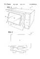
- FIG. 1is a perspective view of a microwave oven constructed in accordance with this invention, showing a partially disassembled door assembly;
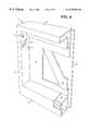
- FIG. 2is an exploded perspective view of the door assembly shown in FIG. 1, showing its three main components;
- FIG. 3is a plan view corresponding to FIG. 2 and showing how the three components of the assembly fit together to form the door of the microwave oven of FIG. 1;
- FIG. 4is a sectional perspective view of an assembly of two of the components of the door construction, namely a door panel and a surround;
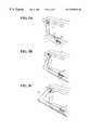
- FIGS. 5 ( a ), 5 ( b ) and 5 ( c )are a sequence of partial perspective views of the complete door assembly, showing a third component—a communications module—in three alternative positions;
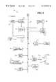
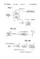
- FIG. 6is a block diagram showing the hardware architecture of a core processing module within the communications module of the invention.
- FIG. 7is a block diagram of active network termination using ADSL
- FIGS. 8 ( a ) and 8 ( b )are block diagrams of optional communications circuits within the core processing module for handling ADSL and RF TV signals;
- FIG. 9is a block diagram of software module architecture of the core processing module.
- FIGS. 10 ( a ) and 10 ( b )illustrates two example web pages that can be displayed by the communications module to provide access to Internet and television content;
- FIG. 11is a flow diagram illustrating switching between ‘standby’, ‘on’ and ‘off’ modes, for example for the purposes of power management;
- FIG. 12is a part-sectioned frontal perspective view of the microwave oven of FIGS. 1 to 5 , showing a camera mounted within the cooking compartment of the oven conveying an image of the contents of the cooking compartment to a display upon a communications module on the front of the oven;
- FIG. 13is a block diagram illustrating three elements of a communications system according to the invention, the microwave oven of FIG. 1 being the first of those elements;
- FIG. 14is a block diagram of a portal being the third of the elements shown in FIG. 13 .
- a microwave oven 1comprises a generally cuboidal hollow cabinet 2 whose open front is closed by a hinged door 3 offset to one side to provide space for a fixed control and display surface 4 beside the door 3 .
- the oven 1is of familiar appearance to those used to ordinary microwave ovens.
- the door 3is an assembly of three main components. That assembly 3 is best shown in FIGS. 2, 3 and 4 , to which reference is now made.
- the first component of the door assembly 3is a door panel 5 hinged permanently to the body of the oven 1 .
- the door panel 5is a thin metal pressing that effectively replaces the door of a traditional microwave oven and so performs all necessary sealing functions to ensure operational safety. So, the microwave oven 1 can operate safely with only this door panel 5 in place.
- the door panel 5carries latching hardware on its rear surface cooperable with corresponding latching means on the oven cabinet 2 , although this hardware can be of standard design and so is not shown.
- the door panel 5is opaque and carries an array of mounting lugs 6 on its exposed front surface.
- the mounting lugs 6are positioned to correspond with and to be received by mounting holes (not shown) in the rear surface of the second component of the door assembly, namely a surround 7 .
- the surround 7snap-fits to the door panel 5 by co-operation between the mounting holes and the mounting lugs 6 .
- the surround 7is an oblong perimeter frame of hollow members—two uprights 8 connected by two cross-members 9 —that between them define a shallow generally oblong recess 10 .
- the front of the recess 10is open and its back is defined by a web that is cut out to form a cantilevered spring member 11 .
- the spring member 11is inclined forwardly at its lower, free end to protrude into the recess 10 .
- the recess 10receives a third component of the door assembly 3 , namely a communications module 12 .
- Mating partshold the communications module 12 in the recess 10 , these parts comprising hinge openings 13 and locating openings 14 in the uprights 8 of the surround 7 , which openings receive, respectively, hinge pins 15 protruding from near the top of each side of the communications module 12 , and locating pins 16 protruding from the communications module 12 just below the hinge pins 15 .
- the thickness and shape of the communications module 12matches the shallowness and shape of the recess 10 , thus enabling the communications module 12 to lie flush with the front face of the surround 7 as shown in FIG. 5 ( a ). Nevertheless, the communications module 12 can be tilted up by pulling its lower edge out of the recess 10 , to either of two positions as shown in FIGS. 5 ( b ) and 5 ( c ). This improves visibility of the display carried by communications module 12 when the oven 1 is situated on a low surface.
- the communications module 12hinges about the hinge pins 15 during this movement.
- the locating openings 14are shaped to define detents 17 for the locating pins 16 to hold the communications module 12 in the positions shown in FIGS. 5 ( b ) and 5 ( c ), the detents 17 being in the lower edge of each locating opening 14 so that the locating pins 16 are held therein by force of gravity acting on the communications module 12 .
- the hinge openings 13are large enough to permit the hinge pins 15 to float within the hinge openings 13 as the locating pins 16 move in and out of the detents 17 of the locating openings 14 .
- the spring member 11 of the surround 7bears against the rear of the communications module 12 when the module 12 is mounted in the recess 10 .
- the spring member 11biases the communications module 12 forwardly out of the recess 10 , which must therefore be pushed into the recess 10 against this bias when being mounted in the recess 10 .
- the communications module 12is retained against this bias by a sprung latch 18 in the lower across-member 9 of the surround 7 that engages with a lug (not shown) in the lower edge of the communications module 12 when the communications module 12 is pressed fully into the recess 10 .
- the latch 18When the latch 18 is pressed, it disengages from the lug and allows the spring member 11 to push the lower edge of the communications module 12 out of the recess 10 .
- the lower edge of the communications module 12can then be grasped by a user and lifted into the desired angular position, whereupon the module is released to allow the locating pins 16 to fall into the appropriate detents 17 of the locating opening
- Stowing the communications module 12 back into the position shown in FIG. 5 ( a )is a reversal of this, involving lifting its bottom edge slightly to free it from the detents 17 and then pivoting the module 12 back towards the vertical against the bias force of the spring member 11 .
- the lug at the lower edge of the module 12engages with the latch 18 and the module 12 can be released.
- each different surround 7defines a standard recess 10 adapted to receive a standard communications module 12 . So, by using the surround 7 as an intermediary or adaptor in this way, a standard communications module 12 can be fitted neatly to any of several completely different microwave ovens without calling for major tooling investments from their manufacturers. The same principle can of course be applied to any appliance.
- the communications module 12could be manufactured by numerous companies that do not necessarily have appliance manufacturing expertise. Conversely, appliance manufacturers that do not necessarily have a high-technology capability could use the module simply by providing appropriate mounting hardware.
- the communications module 12contained in turn within the microwave oven door.
- the dooris about 28 cm high, about 40 cm wide, and about 4 cm thick.
- the entire door assembly described abovemust therefore fit within this volume, confining the communications module 12 itself to somewhat less than this volume.
- the electronics and especially the display within the communications module 12must be shielded from potential sources of heat, especially in combination microwave/convection ovens or in dual-function microwave ovens that have IR heating elements to brown the food being cooked.
- the communications module 12is a self-contained unit that can be integrated into the door 3 of the microwave oven or indeed similarly integrated or otherwise attached to other appliances around the home or workplace.
- the communications module 12has flying leads (not shown) for power and communications that can be routed through e.g. the door hinge of a microwave oven to a convenient position within the oven, terminating with a suitable external I/O panel.
- the communications module 12can be used on its own, independently of a supporting appliance, to serve various other functions.
- a stand-alone communications module 12could perform as a communications and entertainment module for use in hotels. Suitably programmed and connected, one such module 12 could replace the TV, the movie set top box and the telephone within a hotel room. Additionally, this module 12 could allow a user to read his or her e-mail in the hotel room by configuring the module 12 to emulate their own PC, for example using a smartcard securely to store and download configuration information to the module. These are just a few possibilities: there are myriad uses to which such a compact and configurable module 12 could be put.
- substantially the entire front of the communications module 12is defined by an LCD display 20 having a touch screen overlay that is not visible in the drawings.
- the LCD display 20is a widely-available and economical 12.1′′-diagonal TFT-type flat panel including a backlight facility, although it may be possible to use a lower-cost alternative such as a reflective-type LCD that does not require backlight control.
- the size of the LCD display 20will ultimately be dictated by the size of the microwave oven door. Display resolution of 800 ⁇ 600 is deemed adequate for present purposes, operating on an SVGA input signal.
- the module 12can be factory pre-set for optimum operation in SVGA mode, although VGA compatibility is also possible. There is considered to be no need for manual adjustment of brightness or contrast.
- the touch screen overlayis a five-wire resistive touch screen operating under the control of appropriate control electronics and a Windows CE driver, suitably having a resolution of 4096 ⁇ 4096 and achieving positional accuracy of ⁇ 1%.
- the communications module 12has some means of indicating that power is on, for example a ‘power-on’ LED. This objective may, however, be achieved by running a screen saver on the display 20 .
- the communications module 12So far as the user is concerned, all operation of the communications module 12 will be via the touch screen, or by an IR remote control (not shown).
- the microwave oven 1itself can be controlled via the communications module 12 but, for safety purposes, it is envisaged that the remote control will have no ability to switch the microwave oven 1 into a cooking mode: this is reserved for the touch screen. In this way, it is ensured that the user is always present at the start of cooking and that, for example, someone putting something heavy onto the remote control cannot inadvertently start the oven 1 cooking.
- any set-up controls requiredare positioned internally within the communications module 12 so that they are accessible to production and service personnel but are not available to the user.
- the communications module 12relies upon the quality of its user interface to appeal to those with low computer literacy skills and little or no online experience, but who are familiar with using a microwave oven, who typically use paper diaries & noticeboards, and who are aware, at least in outline, of the use of touch screen devices.
- the user interfaceprovides a common interface by which a user of the system can select, access and interact with the communications module 12 and the general cooking function of the oven 1 with which it is associated.
- the display screen 20 with its touch screen overlayis arranged as a graphical user interface and is provided with an icon-based tool bar. This allows for ease of access and choice of the appropriate functionality afforded by Internet tools such as standard web browsers, and achieves quick and ready access to functions commonly arising in relation to electronic mail, electronic banking, electronic shopping and personal organizer facilities of the system.
- the display 20provides a user interface not only for the general cooking functions of the oven 1 but also for the control and management of data and the Internet access achieved by means of the communications module 12 .
- a childproof latch or an optional parental lock-out codemay be employed to alleviate concerns as to safety and restricted content.
- the LCD display 20is sandwiched between the touch screen overlay and a core processing module 21 (not shown in FIGS. 1 to 5 , but see FIG. 6 for its hardware architecture) situated behind the display 20 within the communications module 12 .
- the core processing module 21can therefore be connected directly to the display 20 and the touch screen overlay, to the benefit of cost and reliability; for further cost-effectiveness, the core processing module 21 is suitably embodied within a single PCB.
- a single DC power supply module(not shown) is provided within the communications module 12 , and is preferably capable of accepting a universal voltage input (100-250 V 50/60 Hz AC) to cater for the main supply systems of different countries.
- a voltage selectormay be provided to tailor the module 12 to the country of sale. However, if such a selector is provided, it is preferably inaccessible to the consumer so that the core processing module 21 cannot easily be damaged by being set to the wrong voltage.
- the preferred style of power connectoris a permanently attached mains cord, or alternatively an approved 3-pin bulkhead attached mains connector.
- the hardware architecture of the core processing module 21is set out in FIG. 6 .
- This architecturerelates to a cable-connected unit because the preferred, default communications sub-system is cable. Cable provides downstream video and data and an upstream data channel, one connection thus being all that is necessary to transmit TV and allow Internet access.
- the cable modem 22 and MPEG decoder 23 shown in FIG. 6are specific to that application.
- MNSMultimedia Cable Network Services
- DOCSISData-Over-Cable Service Interface Specification
- the DVB/DAVIC Open Standardsupports digital TV/Video, interactive services and telephony broadband networks. This provides the ability to display digital TV on a monitor.
- the European standard under DVB/DAVIC(ETISI-ETS 300 800 & DAVIC 1.5) has been accepted in South America and in much of Asia Pacific.
- the MCNS/DOCSIS standardwas initiated by the North American cable operators and media companies. This standard is obviously strong in North America but it is also used in parts of Asia Pacific.
- Both these standardsprovide an MPEG 2 stream and an IP stream, but there are significant differences in the types of encoding used to transfer data within the MPEG transport stream. As these differences mean that the two standards are not interchangeable, the core processing module 21 supports both of these standards.
- processorsthere is a wide choice of processors but, having regard to the software architecture set out below, the chosen processor 24 should be capable of supporting Microsoft's Windows CE. Of course, the chosen processor 24 must also have processing performance deemed adequate for any given application.
- Several vendorsprovide such processors, for example as listed in the Microsoft web site at www.microsoft.com. The name Microsoft and the names of its products referred to herein are acknowledged as trade marks.
- the memory resources of the core processing moduleare: system memory 25 , typically 16 Mb of SDRAM; boot memory 26 , typically 1 Mb of Flash EPROM used to store the system BIOS and also code for self-diagnostic functions; program download memory 27 , typically 16 Mb of EEPROM; and video memory 28 , typically 2 Mb of Video RAM.
- An on-board VGA LCD display driver 29provides video support.
- the display driver 29must be Windows CE compatible and must support TFT-type flat panels including LCD backlight control 30 .
- Touch screen control electronics 31employ a Windows CE driver for operation of the touch screen overlay.
- An audio controller 32 and signal amplifier 33support input from a microphone 34 and mono output to a speaker 35 , minimum of 1 W RMS. Cost-effectively, the microphone 34 and the speaker 35 are mounted directly onto the PCB of the core processing module 21 to eliminate interface cable and connector costs. Suitably configured, the communications module 12 thereby has the ability to operate as a hands-free telephone, optionally using Internet telephony or being connected directly to the subscriber's telephone, service provider through the switched network.
- a multi-I/O peripheral controller 36controls the microwave oven 1 , for which purpose an 8 bit data port (not shown) is made available on the CPU bus 37 for the oven manufacturer to interface with the conventional oven control devices.
- the controller 36also controls an IR port (not shown).
- An IR interface(not shown) is provided for interfacing with external IR control devices such as an IR mouse, an IR keyboard or an IR remote controller such as used for TV.
- An appropriate IR interface devicecan be mounted directly onto the PCB of the core processor module 21 .
- the core processing module 21should therefore also have the ability to support ADSL connection where the video/TV content is appropriately formatted at the head end prior to transmission via an ADSL link.
- ADSLAsymmetric Digital Subscriber Line
- an RF inputshould also be provided for the video/TV signal.
- the cable modem 22 and MPEG decoder 23 shown in FIG. 6can be supplemented by the circuitry shown in FIGS. 8 ( a ) and 8 ( b ).
- FIG. 7to explain the options for network termination using ADSL. If ADSL connectivity is required, then the necessary network termination (NT) hardware should be provided external to the core processing module 21 as shown in FIG. 7 .
- the connection between the NT 38 and the core processing module 21should be an Ethernet connection.
- active NTTwo types of network terminators are possible at the consumer premises, namely active NT and passive NT.
- active NTas shown in FIG. 7, the ADSL modem 39 is part of the active NT point 38 and is provided by the telecommunications supplier.
- the output from the ADSL modem 39can be in a number of formats including Ethernet.
- passive NTonly the POTS splitter 40 is provided by the telecommunications supplier and so the consumer is expected to provide the appropriate ADSL modem 39 in each network end point. From the telecommunications supplier's viewpoint, active NT is preferred. However, for certain forms of xDSL such as VDSL where the upstream and downstream data rates are both equally very high (up to 26 Mbits/sec symmetrical), then a dedicated modem in each end point is desirable.
- the form of xDSL that is most suitableis ADSL, in which upstream rates of up to 1 Mbit/sec and downstream rates of up to 8 Mbits/sec are obtainable.
- the core processing module 21should provide an Ethernet connection for the purpose of connecting to the output of the external ADSL modem, 39 as shown in FIG. 8 ( a ).
- An RJ45 connector 41is illustrated for this purpose in FIG. 8 ( a ), although an RJ11 connector can be used in the alternative.
- a coaxial connector 42feeds the RF TV signal to an appropriate RF TV tuner 43 , which in turn feeds an RF decoder 44 that supplies audio information to the audio codec 32 and video information to an NTSC/PAL to VGA converter 45 , which in turn supplies VGA-formatted video information for use by the display driver 29 .
- the physical communications interface of the communications module 12is a group of connectors provided on the end of a flying lead cable connected to the module 12 .
- the group of connectorscomprises an F-connector available for connection to a cable network, an RJ45 or RJ11 connector available for connection to an external ADSL modem, and a co-axial connector available to accept RF TV input.
- These connectorscan of course be replicated on any appliance with which the communications module 12 is integrated. In any event, it is a design objective that an appliance including the communications module 12 shall require no special tools for installation and so should be installable by the customer, assuming that the site is properly prepared with communications cabling and power points.
- the core processing module 21will use as its operating system Microsoft's TVPAK software solution.
- Microsoft's TVPAKis a specialized version of its Windows CE operating system, developed for the demands of television set-top boxes.
- Windows CEis a reliable, flexible and compact operating system that provides functionality including multitasking, multithreading and specialized graphics handling for television pictures.
- Microsoft TVPAKprovides, supports and is compliant with a broad range of television industry standards and hardware including:
- DirectX support for high-performance graphics handling for television picture display and manipulationis provided.
- FIG. 9illustrates the software modules within the currently preferred implementation of the invention.
- Microsoft's TVPAK Windows CE implementationfollows a set-top box architecture with hardware and software dedicated to the task of Internet and television service provision.
- Each box in FIG. 9represents an available software interface definition defined by Microsoft, with the exception of the microwave oven control whose design will be within the compass of a skilled technician having regard to the operational requirements of the oven.
- the Internet Explorer Browser 46is the single controlling application that provides the primary user interface for both television and web content and potentially microwave oven control.
- HTML 47is the Internet standard that allows the web content to be displayed. HTML 47 can reference ActiveX controls 48 that allow television pictures to be embedded within the page. HTML can also reference ActiveX controls 48 that control microwave oven operation.
- Microsoft TVPAKalso supports the Microsoft Broadcast Service (BCS) architecture.
- BCS architectureadds components to the Windows CE operating system that, in addition to basic TV control, provide management of audio/video streams; development electronic program guides (EPG); conditional access (CA) pay-per-view services; and processing of broadcast data (sub-band information, e.g. subtitles).
- EPGdevelopment electronic program guides
- CAconditional access
- broadcast datasub-band information, e.g. subtitles
- Microsoft TVPAKalso includes the non-specialized Windows CE's Internet services.
- Windows CEincludes access to the Internet using TCP/IP and comes equipped with a full set of access utilities, as follows.
- SSLSecure Socket Layer
- the Internet Explorer Browser 46is provided by Microsoft as part of its TVPAK. The following sections detail customizations of the browser that are required to allow it to operate successfully within the communications module 12 .
- the softwareWhen started, the software starts the Internet Explorer Browser 46 and loads an HTML home page located locally on the communications module 12 . This allows the module to function even when not connected to a network.
- Local page(s)could potentially be customized for the vendor or manufacturer of the appliance, or the service provider. If microwave oven control is accessed through the Internet Explorer interface, the web-page control pages would also be located locally on the communications module 12 .
- the communications module 12prevents the possibility of someone building a remote web page and attempting to control the microwave oven 1 . Only local web pages will be able to access the ActiveX control that controls the microwave oven 1 .
- the communications module 12includes security provisions that emulate the Microsoft wallet, which provides a secure mechanism for the storage and transmission of credit card information. For privacy reasons, personal information on user and credit information will be lost on loss of power.
- the communications moduleWhen accessing a secure web page, the communications module will display a pad-lock indicating the use of secure sockets.
- the communications module 12When a user selects a control on a web page that requires text entry, the communications module 12 will automatically present a software keyboard on the display 20 .
- the keyboardwill overlay the Internet browser display presenting a full “qwerty” keyboard with digits, delete and enter keys.
- the keyboardwill also attempt to auto-complete an entry when a previous entry matches what the user types. Again for privacy reasons, auto-complete information will be lost on power loss.
- the communications module 12will maintain a list of redirection URLs. If a user is linked to or types in a URL that exists in the redirection list, the user will be redirected to a corresponding match in the list.
- This listis to ensure that users of the communications module are provided with the highest quality of service when specialized versions of the service exist. For example, instead of linking to the default Amazon (trade mark) web site http://www.amazon.com, users could be taken to a ‘microwave’ version http://microwave.amazon.com. Users can thereby be directed to value-added services where applicable, allowing for e.g. revenue generation.
- An up-to-date redirection listcan be downloaded to the module 12 on each power-up and initial connection to the content service provider.
- BCSbroadcast services
- TV control 49A high level ActiveX control that can be embedded into a web page.
- the controldisplays a full motion television channel.
- the controlis supplied by Microsoft.
- A/V manager 50Used by the TV Control 49 , the A/V Manager 50 uses the high performance DirectX graphics engine within Windows CE to draw the television picture onto the video display.
- the A/V Manageris supplied by Microsoft.
- Conditional access manager 51is a set of ActiveX controls used by web pages and web script to access parental control and other services including encrypted or pay services.
- Conditional Access ActiveX controlsare provided by Microsoft. Underlying the controls is a ‘CA service provider’ which must be developed to match the content provider entitlement system.
- EPGElectronic program guide 52 :
- the EPG ActiveX controloperates continuously in the background collecting programming information.
- the EPGrelies upon the web browser to present a user interface and only provides access to the programming database.
- An ActiveX control to access EPG informationis provided by Microsoft. Underlying the controls, an ‘EPG loader’ must be developed to match the in-band, out-of-band broadcast mechanism of the content provider.
- conditional access manager 51 and the electronic program guide 52operate upon broadcast data 53 .
- the kernel 54provides the familiar Win 32 API used extensively by the Internet Explorer Browser and Broadcast Services.
- the Windows CE kernel 54uses an OEM adaptation layer (OAL) to access machine specific hardware. Building the communications module around standard industry processors, memory and buses allows the use of Microsoft supplied OALs, where possible.
- OEM adaptation layerOAL
- Windows CE servicesallow network applications, including the Internet Explorer Browser, to access the physical hardware connected to the network.
- Connection to a cable networkwill require a cable modem interface; the Windows CE networking subsystem will communicate to the modem interface using an NDIS interface driver.
- Windows CEprovides a driver 55 to connect the IR receiver to the Windows CE network subsystem.
- the IR receiverwill allow ActiveX objects on the user interface to receive remote-control events.
- Windows CEuses drivers to allow hardware to be controlled from Windows CE applications. As shown in FIG. 9, a number of drivers will be required to access device-specific hardware.
- the video decode hardware 56takes a data stream from the cable modem 39 and translates it into a video display. This translation can be computationally expensive and benefits from hardware acceleration. To avoid the need to develop a unique driver, the video decode driver 56 chipset is preferably selected on the basis of having a Windows CE driver.
- the sound 57 and video 58 hardwarerequires DirectX drivers to provide a rich audio and video presentation. Again, the sound/video chipset selection should be based upon having a Windows CE driver to avoid the need for a unique driver.
- the touch mouse driver 59translates touch events on the touch screen into mouse events. Such a driver 59 will generally be available from the touch screen hardware vendor.
- the microwave driver 60is a specialist driver to control the oven operation, developed to match the operational requirements of the oven 1 .
- the Internet communications capability of the communications module 12supports the capability to update the system software by remote download. Download is preferably transparent to the user and happens in the background of other tasks. When download is complete, the communications module 12 suitably waits for a period of inactivity before momentarily interrupting service to start the new software, without any user intervention.
- Softwarecan be downloaded in this way using the Internet FTP protocol.
- An FTP downloaderis embedded as part of the Microsoft Internet Explorer and WEB servers.
- the latest downloaded softwarewill be persistently stored in EEPROM 26 in case of a restart.
- the communications modulewill require twice the image size EEPROM (16 Mb) to allow it to store the complete valid running image and a potentially near complete download image.
- the communications modulewill in any event have one complete valid application image continually stored in EEPROM 26 in case of power failure.
- FIGS. 10 ( a ) and 10 ( b )illustrate two example web pages that provide access to Internet and television content.
- FIG. 10 ( a )illustrates Internet and TV content in which TV content is shown as an ActiveX-generated frame 61 beside TV controls 62 and general web information 63 such as sponsored adverts relevant to the TV transmission, or banner advertising to which the user can respond by ‘clicking through’.
- FIG. 10 ( b )illustrates TV-only content in which the ActiveX control displays a TV picture 64 occupying substantially all of the display 20 . Access to microwave-specific services can be obtained by the same techniques.
- FIG. 11shows how the communications module can switch between the three possible states of ‘standby’ 65 , ‘on’ 66 and ‘off’ 67 .
- the useractivates a standby mode 65 , for example by pressing an appropriate key on the touch screen overlaying the display 20 , to switch the communications module 12 from ‘on’ 66 to ‘standby’ 65 .
- a time-out meansto switch the communications module 12 automatically from ‘on’ 66 to ‘standby’ 65 when a predetermined time has elapsed without the presence of a user having been detected, or without the touch screen being touched.
- the communications module 12reverts from ‘standby’ 65 to ‘on’ by detecting the nearby presence of a user or by receiving a touch input from the user as aforesaid.
- the useralso has the option of toggling the communications module between ‘on’ 66 and ‘off’ 67 states.
- Exit from the standby state 65may be effected by sensing the proximity of a user and/or a user's touch upon the touch screen.
- a proximity sensor(not shown) is included to detect the presence of a user within close proximity to the communications module 12 .
- the proximity sensorprovides a means for switching the communications module 12 from its standby mode 65 to its full power-on state 66 .
- the sensor in conjunction with a time-out meansprovides a way to switch the communications module 12 from ‘on’ 66 to ‘standby’ 65 when a predetermined period of inactivity is observed by the sensor.
- An appropriate proximity sensorwould be a standard PIR (passive infra red) sensor.
- the sensorshould have a near range capability to ensure that the system only switches to full power-on mode 66 when a user comes close to the communications module 12 .
- an 8-bit data portmay be made available to a microwave oven manufacturer to interface with the conventional oven control devices. This port may also serve as an interface for the proximity sensor.
- the proximity sensorhelps the disabled.
- the communications module 12can be programmed to support voice recognition so that speaking to the module 12 can control its operation and that of any appliance that the module 12 in turn controls.
- the aforementioned microphone 34can be used for that purpose.
- a displayit is also possible for a display to be maintained when in the standby mode 65 , in the manner of a screensaver. Whilst this may not save much power, such a standby display would be an excellent opportunity for advertising at the heart of the home. If downloaded periodically from the communications network to which the communications module 12 is connected, such advertising can be targeted in various ways. For example, it can reflect that household's demographic standing or its recent buying or browsing patterns, or it can simply be adapted to suit the weather or the time of day.
- the advertising conceptextends to local information services, such as what's happening today at the town hall, what's on tonight at the local cinema, and so on. It is also possible to define affinity groups within a community to whom special services are offered relating to their shared interest such as fishing, motoring, do-it-yourself and other hobbies.
- the inventionalso lends itself to participative games, playing a lottery or other gambling games.
- participative gamesplaying a lottery or other gambling games.
- the inventioncan be a major enabling factor in home automation, the communications module 12 becoming a home server for basic information functions to wireless phones, personal digital assistants (PDAs) etc.
- the communications module 12can also be linked to security systems, for example being linked to a CCTV camera to display who is at the front door when the doorbell rings.
- security systemsfor example being linked to a CCTV camera to display who is at the front door when the doorbell rings.
- the essential simplicity of the communications module 12is such that it can be used as a family organizer, note pad or notice board at the hub of the domestic environment.
- a barcode readerto the communications module 12 or to the appliance itself gives further application options. It is envisaged that the reader could be used to re-order articles that are already within the appliance owner's home, such as groceries, clothes, videos or any other item that has a barcode printed upon it.
- a smartcard readercan be added to the communications module 12 or to the appliance with which that module 12 is associated, thus opening up further application options.
- smartcard functionalitywould allow true private banking. For example, a user can load electronic cash (e-cash) onto his or her e-cash card or can spend such e-cash upon purchases located when browsing the Web using the communications module 12 .
- e-cashelectronic cash
- a smartcardcan be used for security purposes, or to configure, limit or otherwise define the service offered to the user.
- the service offeredcan reflect a user's preferences stored on the smartcard or can be limited in accordance with the user's age or level of subscription payment.
- the smartcard readermust be positioned in an easily accessible place, and should retain the card during transactions to prevent removal of the card before the transaction is complete.
- the smartcard readercould of course retain the card after the transaction is complete, until the user is ready to pick up the card again.
- the microphone, barcode reader or smartcard readercan be positioned, conveniently, on the fixed control and display surface 4 on the front of the microwave cabinet 2 beside the door 3 .
- Another hardware optionis to give the communications module 12 a printer driver facility to drive an external printer. This would be useful for generating coupons relating to marketing offers advertised on the LCD display 20 , and of course to keep hard copies of any advertising or other material thus displayed.
- the communications module 12could be programmed to download and print a newspaper ready for its owner getting up each morning.
- FIG. 12Another aspect of the invention is illustrated in FIG. 12 .
- This aspect of the inventionarises from the opacity of the microwave oven door 3 , meaning that the user no longer has a window to view the microwave's food compartment to determine the progress of cooking or defrosting.
- a camera (CCD or similar) 68is provided within the cooking compartment 69 of the microwave oven 1 , in order to permit viewing of the contents 70 cooking or defrosting within.
- the image of the oven contents 70is displayed when necessary on the LCD display 20 , and may be displayed by default whenever the microwave oven 1 is operational but the display 20 is not being used for Internet, e-commerce, or home networking functions.
- microwave oven 1Even if the microwave oven 1 is being used for such functions that require the display 20 while also being used for cooking or defrosting, various means such as a mechanical switch (not shown), an icon on the display 20 , voice recognition, or otherwise may be used to display the contents 70 of the microwave oven 1 .
- a mechanical switchnot shown
- an icon on the display 20may be used to display the contents 70 of the microwave oven 1 .
- voice recognitionor otherwise may be used to display the contents 70 of the microwave oven 1 .
- a similar methodcould be employed to deactivate viewing of the contents 70 .
- a fixed camera 68could be used in conjunction with an existing microwave oven turntable 71 to view the contents 70 being cooked or defrosted from all angles. Users can thereby view the food contents 70 of the microwave 1 in much the same way as they do when using a normal microwave oven.
- the inventionfurther contemplates the optional use of a camera 68 capable of capturing infrared or other non-visible wavelengths in conjunction with a microwave oven 1 .
- a camera 68could be used to sense the extent to which food items 70 are cooked or defrosted, as well as uneven cooking or defrosting, overcooking or excessive defrosting, or undercooking or inadequate defrosting.
- the information that the camera 68 captures about the food item(s) 70could then be used to allow the microwave oven 1 automatically to reprogram the cooking or defrost time and power levels. If implemented appropriately, this could potentially allow the microwave oven 1 automatically to cook or defrost to perfection while avoiding the typical trial-and-error cycle of checking if done and then restarting for a few more minutes.
- An infrared or similar camera 68could also prove useful as a safety feature. Oftentimes, an individual will stick their finger in the food 70 or touch a plastic wrap to see if the food 70 is done. If it has overcooked, there is the danger of burns and especially of steam scalds if plastic wrap is used.
- the infrared camera 68could address safety issues via either of two mechanisms: 1) simply by alerting the user that the food 70 is at a dangerous temperature; or 2) avoiding dangerous food temperatures entirely by enabling the microwave oven 1 automatically to reprogram the cooking time and temperature to ensure perfect cooking.
- the LCD display 20could display a visible color-coded representation of the infrared image of the food 70 being cooked or defrosted, thereby assisting the user in judging the progress of cooking or defrosting.
- the communications moduleneed not necessarily be connected to the Internet: it may, for example, be connected only to a domestic broadband system supplying just TV/radio content.
- the communications modulecould be configured to receive IPPV (impulse pay per view) transmissions for pay-TV purposes.
- the appliance 1itself is just one of three elements of a communications system that embodies the invention in its various forms. These three elements of the communications system are represented in FIG. 13 of the drawings. It will be seen that the other elements are a broadband online connection 72 that allows ‘always-on’, high speed access to the Internet, and a broadband portal 73 that offers functionality and services to ensure the continuing loyalty of intermediate customers in an open access environment.
- the appliance 1has been described technically in detail above. As a business proposition, much of its success must naturally flow from the superior technical facilities and interface that it offers its users. However, the modular construction reduces the need for product development investment by the appliance manufacturer and so lessens the need to grant exclusivity to any one appliance manufacturer. The grant of such exclusivity might otherwise be necessary to recoup development costs, to the possible detriment of market penetration and hence propagation of the technology.
- the technical features of the broadband online connection 72are also well known, the main alternatives of cable and xDSL having been outlined above. Basically, cable is preferred to xDSL for its ease of installation and better TV capabilities but, for the purposes of the invention, either is much better than a standard dial-up telephone connection.
- a standard dial-up connectionis not capable of supporting the ideal always-on, always-available characteristics of the appliance 1 , or the real-time, high quality access to content that users will demand.
- Alternativessuch as full ISDN, satellite telephony and T 1 are variously expensive to install and to run, are unsuitable in the domestic context, and do not match the performance of xDSL or, particularly, cable. In any event, competition between cable and xDSL is increasing and this will drive broadband availability upwards.
- ISPInternet service provider
- the ISP 74connects to the appliance 1 in turn via a local loop 77 and modem 39 .
- the network architecture that connects the appliance 1 to the Internet 75 via the ISP 74is very much more complex, involving multiple cascading levels of leased bandwidth terminating in network access points that connect to the Internet itself.
- ISPInternet service provider
- the broadband portal 73provides access to content such as today's news, and user services such as e-mail.
- the portal 73also embodies agreements with e.g. retailers and financial service providers, to whose web pages it provides hypertext links. Again, portal developments and/or agreements with retailers and so on can be outsourced, possibly with the incentive of equity partnerships to share risk and reward.
- the portal 73suitably carries banner advertising and section sponsorship.
- Banner advertisingmay be paid for on a ‘click-through’ basis proportional to the number of users who respond to the advertisement by ‘clicking through’ the banner advertisement.
- This direct customer feedbackassists in targeting the advertisements and in pricing performance-based advertising.
- Advertisementscan be targeted according to user action within the site (for example, a user may be more likely to click on a banner while shopping than while reading news) and/or according to previous shopping behavior. This ensures the relevance of the advertisement and so improves the prospect of a click-through and hence of generating advertising revenue that depends upon the click-through.
- Section sponsorshipcan be structured in various ways, and has the benefit of a more predictable income stream than banner advertising. For example, while users watch TV, a frame of advertisements around the TV display area could be sold on a sponsorship basis. Additionally, as suggested above, commercials can fill the display like a screen saver when the user is not watching TV or interacting with the portal 73 .
- FIG. 14is a conceptual block diagram showing the functionality of the portal 73 .
- the portalcan be broken down into five main sections: a targeted banner advertisement 74 ; content 75 ; user services 76 ; finance 77 ; and shopping 78 . These latter two sections may be thought of as coming together under the heading ‘transactions’ and so may share many enabling functions.
- a content delivery engine 79takes feeds from third-party content providers such as a news agency 80 and a weather forecasting office 81 and, having regard to input from an adaptive customer profile database 82 , makes available to the content section 75 of the portal 73 whatever content is deemed appropriate to that customer or user.
- third-party content providerssuch as a news agency 80 and a weather forecasting office 81 and, having regard to input from an adaptive customer profile database 82 , makes available to the content section 75 of the portal 73 whatever content is deemed appropriate to that customer or user.
- third-party content providerssuch as a news agency 80 and a weather forecasting office 81 and, having regard to input from an adaptive customer profile database 82 , makes available to the content section 75 of the portal 73 whatever content is deemed appropriate to that customer or user.
- the customer profile database 82is also used by an advertising engine 83 , which targets the banner advertising 74 with reference to the customer profile and also feeds back information on the customer's response to that advertising, so as to update and if necessary adapt the customer profile database 82 .
- Similar feedbackis provided to the customer profile database 82 from a commerce engine 84 , but this time based upon the customer's actual buying behavior.
- the commerce engine 84deals with requests and quotes to and from the customer via the shopping section 78 of the portal 73 , interacting with a product database 85 fed in turn by a catalogue database 86 held by a retailer in its ‘front office’. Interaction also takes place between the commerce engine 84 and the retailer's ‘back office’ for ordering 87 , fulfillment 88 and accounting 89 procedures.
- the usercan buy in various ways, for example through partner retailers, via auctions or in response to classified advertisements.
- a finance engine 90interacts with the finance section 77 of the portal 73 to enable the user to view details such as checking the status of his or her bank account, to perform transactions such as paying bills, and to investigate, apply for or purchase new financial products like pensions or mortgages.
- the finance engine 90is connected to the banking system 91 for this purpose. Although not shown, it would equally be possible to provide for feedback from the finance engine 90 to the customer profile database 82 , or for the commerce engine 84 to handle purchases of financial products instead of the finance engine 90 .
- the appropriate iconis selected on a touch screen toolbar on the display 20 that defines the user interface.
- a message requesting the user to enter authentication datais displayed and subsequently, a series of options relating to the various facilities available to the user is displayed on the display 20 .
- the userselects the required option and is requested to enter details relating to the transaction.
- the authentication transaction detailsare transmitted over the Internet to an appropriate remote management unit within the banking system 91 where verification of the authentication data takes place and on validation, the transaction details are processed.
- the electronic banking facilitycan be used for payment transaction, ordering of cheques, travelers cheques, bank drafts etc., and for statement or balance requests.
- the user services section 76provides for personal services and for site-internal functions like a help facility and an internal search engine.
- Myriad personal servicescan run within the user services section 76 of the portal 73 . Examples are user profiles for personalized news; a shopping account for e.g. shopping and credit card details; a loyalty scheme or club membership; personal organizer functions like calendaring or scheduling; e-mail; a real-time messaging service; and personal home pages.
- the appropriate icon on the touch screen tool baris selected and the core processing unit 21 causes the appropriate information to be displayed on the display 20 .
- the usercan open received mail or compose mail messages by entering data via the keypad on the touch screen or, with speech recognition software, via the microphone 34 in the communications module 12 . The message can then be transmitted to the desired recipient over the Internet.
- the personal organizer facilityallows the user to maintain a diary and request reminders for specific events such as birthdays, appointments and so on, and can maintain Personal data in various spreadsheet programs.
- the functionality of the portal 73can be developed from scratch or in partnership with a major existing portal such as Excite (trade mark), which brings the benefit of existing relationships with retailers and financial services companies.
- aspects of the inventionsuch as the aforementioned redirection list could be used to facilitate closed access which enables access to only selected sites specially adapted to users of the appliance.
- links in such siteswould need to be adapted so that they lead only to similarly-adapted sites but this could be achieved by the redirection list so that redirection takes place locally rather than requiring wholesale adaptation of the sites themselves.
- Enticements to stayare good functional and aesthetic design, convenience, automatic personalization, an attractive and simple interface for TV functionality and an excellent family-oriented portal carrying much of relevance and interest.
- customersmay be discouraged to leave by, for example, the browser opening into a default home page that cannot be changed by the user. It is further preferred that TV viewing can only be requested from that home page.
- the functionality of the microwave oven, or other appliance with which the communications module is associatedcan only be selected via that home page. Once selected, actual control of the TV or appliance can then be delegated to other control means such as the IR remote control or a keypad image on the LCD display 20 operable by the touch screen overlay.
- redirection listitself also preserves revenue streams while allowing open access, by directing users to specific versions of user-selected web sites where such alternatives exist.
- most domestic appliancesreceive operating power by means of a mains supply unit which could also provide a communications channel for access to the Internet, so as to provide for communication of data to and from the domestic environment.
- data input meanscould readily be incorporated into an appliance embodying the present invention such as, for example, a smart tag reader means for reading data from a smart tag associated with a food product being cooked, defrosted or stored in the appliance.
- the present inventionoffers particular advantages in that the domestic appliance concerned is generally incorporated into a specific domestic environment, i.e., the kitchen, and in that the functionality of the domestic appliance is extended. Also, the invention provides apparatus that is much more user friendly than current apparatus allowing for lnternet access and it can readily provide a user interface that allows for ease of reading and therefore interaction within the environment in which the appliance is commonly used.
Landscapes
- Engineering & Computer Science (AREA)
- Human Computer Interaction (AREA)
- Physics & Mathematics (AREA)
- Electromagnetism (AREA)
- Electric Ovens (AREA)
Abstract
Description
Claims (1)
Priority Applications (3)
| Application Number | Priority Date | Filing Date | Title |
|---|---|---|---|
| US09/388,811US6559882B1 (en) | 1999-09-02 | 1999-09-02 | Domestic appliance |
| EP00300353AEP1028604A2 (en) | 1999-02-09 | 2000-01-19 | Domestic appliance with camera to display images of cooking or defrosting food |
| JP2000048581AJP2001074248A (en) | 1999-09-02 | 2000-02-25 | Device and method for controlling domestic electric appliance |
Applications Claiming Priority (1)
| Application Number | Priority Date | Filing Date | Title |
|---|---|---|---|
| US09/388,811US6559882B1 (en) | 1999-09-02 | 1999-09-02 | Domestic appliance |
Publications (1)
| Publication Number | Publication Date |
|---|---|
| US6559882B1true US6559882B1 (en) | 2003-05-06 |
Family
ID=23535615
Family Applications (1)
| Application Number | Title | Priority Date | Filing Date |
|---|---|---|---|
| US09/388,811Expired - LifetimeUS6559882B1 (en) | 1999-02-09 | 1999-09-02 | Domestic appliance |
Country Status (3)
| Country | Link |
|---|---|
| US (1) | US6559882B1 (en) |
| EP (1) | EP1028604A2 (en) |
| JP (1) | JP2001074248A (en) |
Cited By (198)
| Publication number | Priority date | Publication date | Assignee | Title |
|---|---|---|---|---|
| US20020062392A1 (en)* | 2000-06-19 | 2002-05-23 | Sanyo Electric Co., Ltd. | Communication between networks based on different protocols |
| US20020171770A1 (en)* | 2000-08-19 | 2002-11-21 | Matthias Wendt | Television set having additional functions |
| US20020184301A1 (en)* | 2001-01-05 | 2002-12-05 | Emware, Inc., | Web server for communicating with one or more electronic devices through a gateway computer |
| US20030009368A1 (en)* | 2001-07-06 | 2003-01-09 | Kitts Brendan J. | Method of predicting a customer's business potential and a data processing system readable medium including code for the method |
| US20030028259A1 (en)* | 2001-08-02 | 2003-02-06 | Hood Kimberly J. | Household appliance with advertising display mode |
| US20030046326A1 (en)* | 2001-08-28 | 2003-03-06 | Shun Matsuura | Method for creating a schedule, apparatus for creating a schedule, and computer-program for creating a schedule |
| US20030076341A1 (en)* | 2001-10-18 | 2003-04-24 | Hikaru Kuki | Graphical user interface for an appliance network |
| US20030084047A1 (en)* | 2001-11-01 | 2003-05-01 | Williamson Charles G. | Intelligent household networked appliances |
| US20030100964A1 (en)* | 2001-11-29 | 2003-05-29 | Eva Kluge | Electronic product/service manual |
| US20030112268A1 (en)* | 2001-09-11 | 2003-06-19 | Sony Corporation | Device for producing multimedia presentation |
| US20030121910A1 (en)* | 2002-01-03 | 2003-07-03 | Louis Rey | Mail sanitizer and method |
| US20040051645A1 (en)* | 2002-09-16 | 2004-03-18 | Mahloch Gregory A. | Oven with television in the door |
| US6730890B2 (en)* | 2000-11-13 | 2004-05-04 | Barbara Ann Kish | Programmable remote controlled cooking or baking apparatus and method |
| US6853399B1 (en)* | 2000-05-26 | 2005-02-08 | Robert A. Gilman | Kitchen appliance with video display |
| US20050060578A1 (en)* | 2003-09-17 | 2005-03-17 | Sony Corporation | Method of and system for authentication downloading |
| US20050103466A1 (en)* | 2003-11-19 | 2005-05-19 | Landry Kenneth D. | Refrigerator-oven |
| US20050265423A1 (en)* | 2004-05-26 | 2005-12-01 | Mahowald Peter H | Monitoring system for cooking station |
| US6996612B1 (en) | 1999-12-30 | 2006-02-07 | Vignette Corporation | Method of providing information related to activity of a user and a data processing system program product |
| US20060032845A1 (en)* | 2004-08-13 | 2006-02-16 | Mills Nigel G | Oven system with automated customer messages |
| US7051111B1 (en)* | 2000-04-25 | 2006-05-23 | Digeo, Inc. | Multiple source proxy management system |
| US20060137971A1 (en)* | 2002-07-01 | 2006-06-29 | Larry Buchtmann | Method for coating cutting implements |
| US20060140405A1 (en)* | 2004-11-24 | 2006-06-29 | Interdigital Technology Corporation | Protecting content objects with rights management information |
| US7092988B1 (en)* | 1997-05-27 | 2006-08-15 | Jeffrey Bogatin | Rapid cooking oven with broadband communication capability to increase ease of use |
| US20060190357A1 (en)* | 2005-02-09 | 2006-08-24 | Sony United Kingdom Limited | Method for displaying display information |
| US20070033903A1 (en)* | 2005-08-15 | 2007-02-15 | Uhlmann Pac-Systeme Gmbh & Co. Kg | Packaging machine |
| US7188139B1 (en)* | 1999-11-18 | 2007-03-06 | Sony Corporation | Portable information processing terminal, information input/output system and information input/output method |
| US20070067419A1 (en)* | 2005-09-19 | 2007-03-22 | Bennett James D | Dedicated client devices supporting web based service, specifications and interaction |
| US20070143456A1 (en)* | 2003-12-10 | 2007-06-21 | Alex Mashinsky | Exchange of centralized control data |
| US20070168486A1 (en)* | 2005-06-09 | 2007-07-19 | Whirlpool Corporation | Software architecture system and method for operating an appliance exposing key press functionality to a network |
| US20070174864A1 (en)* | 2006-01-25 | 2007-07-26 | International Business Machines Corporation | Coder/decoder enabled television |
| US7251687B1 (en)* | 2000-06-02 | 2007-07-31 | Vignette Corporation | Method for click-stream analysis using web directory reverse categorization |
| US7272786B1 (en) | 2000-07-20 | 2007-09-18 | Vignette Corporation | Metadata, models, visualization and control |
| US7278105B1 (en) | 2000-08-21 | 2007-10-02 | Vignette Corporation | Visualization and analysis of user clickpaths |
| US20070246453A1 (en)* | 2006-04-20 | 2007-10-25 | Lg Electronics Inc. | Cooking apparatus and control method of the same |
| US20070278320A1 (en)* | 2003-12-02 | 2007-12-06 | Honeywell International Inc. | Thermostat with electronic image display |
| US20070288251A1 (en)* | 2005-06-09 | 2007-12-13 | Whirlpool Corporation | Method of providing product demonstrations |
| US20070291716A1 (en)* | 2004-06-02 | 2007-12-20 | Morales Barroso | Universal Ethernet Telecommunications Service |
| US20070298405A1 (en)* | 2006-06-08 | 2007-12-27 | Whirlpool Corporation | Product demonstration system |
| US20080016703A1 (en)* | 2001-11-13 | 2008-01-24 | Larry Buchtmann | Coating for cutting implements |
| US20080100695A1 (en)* | 2006-06-08 | 2008-05-01 | Whirlpool Corporation | Product Demonstration System and Method |
| US20080102743A1 (en)* | 2005-04-25 | 2008-05-01 | Independent, Inc. | Hood mounted display system |
| US20080105134A1 (en)* | 2005-06-09 | 2008-05-08 | Whirlpool Corporation | Appliance network for a networked appliance and a cooking sensor accessory |
| US20080109310A1 (en)* | 2005-06-09 | 2008-05-08 | Whirlpool Corporation | Product Demonstration System and Method |
| US20080109243A1 (en)* | 2005-06-09 | 2008-05-08 | Whirlpool Corporation | Product Demonstration System and Method |
| US20080117339A1 (en)* | 2006-11-20 | 2008-05-22 | Comcast Cable Holdings, Llc | Remote control based content control |
| US20080123557A1 (en)* | 2005-06-09 | 2008-05-29 | Whirlpool Corporation | Appliance network for a networked appliance with a network binder accessory |
| US20080130520A1 (en)* | 2005-06-09 | 2008-06-05 | Whirlpool Corporation | Network for communicating information related to a consumable to an appliance |
| US20080143550A1 (en)* | 2005-06-09 | 2008-06-19 | Whirlpool Corporation | Recipe wand and recipe book for use with a networked appliance |
| US20080143489A1 (en)* | 2005-06-09 | 2008-06-19 | Whirlpool Corporation | Smart coupling device |
| US20080165509A1 (en)* | 2007-01-04 | 2008-07-10 | Whirlpool Corporation | Host With Multiple Adapters for Coupling Consumer Electronic Devices |
| US20080168205A1 (en)* | 2007-01-04 | 2008-07-10 | Whirlpool Corporation | Functional Adapter for a Consumer Electronic Device |
| US20080165505A1 (en)* | 2007-01-04 | 2008-07-10 | Whirlpool Corporation | Door With a Service Interface On An Edge |
| US20080166915A1 (en)* | 2007-01-04 | 2008-07-10 | Whirlpool Corporation | Appliance With an Adapter to Simultaneously Couple Multiple Consumer Electronic Devices |
| US20080165082A1 (en)* | 2007-01-05 | 2008-07-10 | Manico Joseph A | Function enhancing array for multi-frame display system |
| US20080166895A1 (en)* | 2007-01-04 | 2008-07-10 | Whirlpool Corporation | System for Supplying Service From an Appliance To Multiple Consumer Electronic Devices |
| US20080164226A1 (en)* | 2007-01-04 | 2008-07-10 | Whirlpool Corporation | Alternative Hosts for Multiple Adapters and Multiple Consumer Electronic Devices |
| US20080202844A1 (en)* | 2007-01-04 | 2008-08-28 | Whirlpool Corporation | Acoustic chamber as part of adapter |
| US7437268B1 (en) | 2002-12-17 | 2008-10-14 | Vignette Corporation | Systems and methods for analyzing data |
| US20080281919A1 (en)* | 2007-05-09 | 2008-11-13 | University Of Georgia Research Foundation, Inc. | System and Method for Sharing Images |
| US20080287009A1 (en)* | 2007-01-04 | 2008-11-20 | Whirlpool Corporation | Adapter with an access panel for an electronic device |
| US7461120B1 (en) | 2002-07-09 | 2008-12-02 | Vignette Corporation | Method and system for identifying a visitor at a website server by requesting additional characteristic of a visitor computer from a visitor server |
| US20090071952A1 (en)* | 2007-09-13 | 2009-03-19 | Semiconductor Energy Laboratory Co., Ltd. | Semiconductor device and heating system |
| DE102008042804A1 (en) | 2007-10-16 | 2009-04-23 | BSH Bosch und Siemens Hausgeräte GmbH | Cooking equipment i.e. baking oven, for food, has data communication unit for transferring pictures to TV set, computer monitor, personal digital assistant, tablet personal computer, mobile telephone, refrigerator and chimney |
| US20090158188A1 (en)* | 2007-12-14 | 2009-06-18 | Honeywell International Inc. | Configurable wall module system |
| US20090236333A1 (en)* | 2006-02-21 | 2009-09-24 | Rf Dynamics Ltd. | Food preparation |
| US20090236334A1 (en)* | 2006-07-10 | 2009-09-24 | Rf Dynamics Ltd | Food preparation |
| US7603430B1 (en) | 2002-07-09 | 2009-10-13 | Vignette Corporation | System and method of associating events with requests |
| US20090259689A1 (en)* | 2008-04-15 | 2009-10-15 | International Business Machines Corporation | Interactive recipe preparation using instructive device with integrated actuators to provide tactile feedback |
| US20090259687A1 (en)* | 2008-04-15 | 2009-10-15 | International Business Machines Corporation | Interactive Recipe Preparation Using Instructive Device with Integrated Actuators to Provide Tactile Feedback |
| US20090258332A1 (en)* | 2008-04-15 | 2009-10-15 | International Business Machines Corporation | Interactive recipe preparation using instructive device with integrated actuators to provide tactile feedback |
| US20090258331A1 (en)* | 2008-04-15 | 2009-10-15 | International Business Machines Corporation | Interactive recipe preparation using instructive device with integrated actuators to provide tactile feedback |
| US7627688B1 (en)* | 2002-07-09 | 2009-12-01 | Vignette Corporation | Method and system for detecting gaps in a data stream |
| US20100006564A1 (en)* | 2006-02-21 | 2010-01-14 | Rf Dynamics Ltd. | Electromagnetic heating |
| US20100015313A1 (en)* | 2008-07-17 | 2010-01-21 | Harris Scott C | Smart Sensing Oven |
| US7660869B1 (en) | 2000-08-21 | 2010-02-09 | Vignette Software, LLC | Network real estate analysis |
| US20100147823A1 (en)* | 2008-12-17 | 2010-06-17 | Whirlpool Corporation | Oven control system with graphical display |
| US20100165103A1 (en)* | 2008-12-30 | 2010-07-01 | Paul Andreas Adrian | Camera Monitoring Systems And Methods For Electromagnetic Dryer Applicators |
| US7798865B2 (en) | 2007-01-04 | 2010-09-21 | Whirlpool Corporation | Service supply module and adapter for a consumer electronic device |
| US20100248546A1 (en)* | 2007-01-04 | 2010-09-30 | Whirlpool Corporation | Adapter for coupling a consumer electronic device to an appliance |
| US7810343B2 (en) | 2007-01-04 | 2010-10-12 | Whirlpool Corporation | Dispenser with a service interface for a consumer electronic device |
| US7831321B2 (en) | 2005-06-09 | 2010-11-09 | Whirlpool Corporation | Appliance and accessory for controlling a cycle of operation |
| US7865639B2 (en) | 2007-01-04 | 2011-01-04 | Whirlpool Corporation | Appliance with an electrically adaptive adapter to alternatively couple multiple consumer electronic devices |
| US7869201B2 (en) | 2007-01-04 | 2011-01-11 | Whirlpool Corporation | Host and adapter for selectively positioning a consumer electronic display in visible and concealed orientations |
| US7871300B2 (en) | 2007-01-04 | 2011-01-18 | Whirlpool Corporation | Host with multiple sequential adapters for multiple consumer electronic devices |
| US7870753B2 (en) | 2007-01-04 | 2011-01-18 | Whirlpool Corporation | Appliance door with a service interface |
| US20110123689A1 (en)* | 2008-07-30 | 2011-05-26 | Electrolux Home Products Corporation N.V. | Oven and method of operating the same |
| US20110147160A1 (en)* | 2009-12-21 | 2011-06-23 | Whirlpool Corporation | Proximity Sensor Enabled Mechanical Power Coupling System |
| US20110149485A1 (en)* | 2009-12-21 | 2011-06-23 | Whirlpool Corporation | Mechanically Energized Substance Communication Coupling System |
| US20110147417A1 (en)* | 2009-12-21 | 2011-06-23 | Whirlpool Corporation | Substance Communicating Device for Coupling to a Host |
| US20110148223A1 (en)* | 2009-12-21 | 2011-06-23 | Whirlpool Corporation | Mechanically Energized eService Connector System |
| US20110153871A1 (en)* | 2009-12-21 | 2011-06-23 | Whirlpool Corporation | Substance Communicating Device with Activatable Connector and Cycle Structure |
| US20110148651A1 (en)* | 2009-12-21 | 2011-06-23 | Whirlpool Corporation | Substance Communicating Device with Sensor Enabled Connector |
| US20110148650A1 (en)* | 2009-12-21 | 2011-06-23 | Whirlpool Corporation | Mechanical Proximity Sensor Enabled Electromagnetic Service Connector System |
| US20110153821A1 (en)* | 2009-12-21 | 2011-06-23 | Whirlpool Corporation | Mechanical Proximity Sensor Enabled eService Connector System |
| US20110146330A1 (en)* | 2009-12-21 | 2011-06-23 | Whirlpool Corporation | Mechanically Energized Substance Communication Coupling System |
| US20110152024A1 (en)* | 2009-12-21 | 2011-06-23 | Whirlpool Corporation | Mechanical Power Service Communicating Device and System |
| US20110146329A1 (en)* | 2009-12-21 | 2011-06-23 | Whirlpool Corporation | Proximity Sensor Enabled Substance Communication Coupling System |
| US20110147161A1 (en)* | 2009-12-21 | 2011-06-23 | Whirlpool Corporation | Mechanically Energized Mechanical Power Coupling System |
| US20110146819A1 (en)* | 2009-12-21 | 2011-06-23 | Whirlpool Corporation | Substance Communicating Device with Mechanically Energized Connector System |
| US20110153739A1 (en)* | 2009-12-21 | 2011-06-23 | Whirlpool Corporation | Proximity Sensor Enabled eService Connector System |
| US20110146328A1 (en)* | 2009-12-21 | 2011-06-23 | Whirlpool Corporation | Substance Communicating Device with Mechanically Energized Connector |
| US20110148649A1 (en)* | 2009-12-21 | 2011-06-23 | Whirlpool Corporation | Proximity Sensor Enabled Electromagnetic Service Connector System |
| US7978219B1 (en) | 2000-08-30 | 2011-07-12 | Kevin Reid Imes | Device, network, server, and methods for providing digital images and associated processing information |
| US7980088B2 (en) | 2007-01-04 | 2011-07-19 | Whirlpool Corporation | Removable adapter providing a wireless service to removable consumer electronic device |
| CN102141260A (en)* | 2011-04-20 | 2011-08-03 | 申家群 | Internal recycle radiating type nonradiative microwave oven |
| CN102163079A (en)* | 2010-02-23 | 2011-08-24 | 通用汽车环球科技运作有限责任公司 | Method of changing the state of an electronic device |
| US8018716B2 (en) | 2007-01-04 | 2011-09-13 | Whirlpool Corporation | Adapter for docking a consumer electronic device in discrete orientations |
| US20120023971A1 (en)* | 2010-07-29 | 2012-02-02 | Min Deulre | Refrigerator and method for controlling the same |
| US20120048122A1 (en)* | 2009-05-08 | 2012-03-01 | Koninklijke Philips Electronics N.V. | interactive device adapted to interactively communicate with a remote device |
| US20120076351A1 (en)* | 2009-06-15 | 2012-03-29 | Yoo-Sool Yoon | Cooker and control method thereof |
| US8224892B2 (en) | 2000-04-28 | 2012-07-17 | Turbochef Technologies, Inc. | Rapid cooking oven with broadband communication capability to increase ease of use |
| US8326352B1 (en)* | 2000-09-06 | 2012-12-04 | Kevin Reid Imes | Device, network, server, and methods for providing service requests for wireless communication devices |
| US20130186887A1 (en)* | 2012-01-23 | 2013-07-25 | Whirlpool Corporation | Microwave heating apparatus |
| DE102013206405A1 (en) | 2012-05-23 | 2013-11-28 | BSH Bosch und Siemens Hausgeräte GmbH | Household appliance has camera unit having main portion which is movably connected to housing so that camera is in a position to view various regions within housing |
| US8832584B1 (en) | 2009-03-31 | 2014-09-09 | Amazon Technologies, Inc. | Questions on highlighted passages |
| US8954444B1 (en) | 2007-03-29 | 2015-02-10 | Amazon Technologies, Inc. | Search and indexing on a user device |
| US8965807B1 (en) | 2007-05-21 | 2015-02-24 | Amazon Technologies, Inc. | Selecting and providing items in a media consumption system |
| US8992225B2 (en) | 2008-04-15 | 2015-03-31 | International Business Machines Corporation | Monitoring recipe preparation using instructive device and generating an alert to provide feedback |
| US20150105890A1 (en)* | 2012-07-16 | 2015-04-16 | Other Machine Company | System and Method for CNC Machines and Software |
| US9087032B1 (en) | 2009-01-26 | 2015-07-21 | Amazon Technologies, Inc. | Aggregation of highlights |
| US20150213009A1 (en)* | 2014-01-24 | 2015-07-30 | Panasonic Intellectual Property Corporation Of America | Cooking apparatus, cooking method, non-transitory recording medium on which cooking control program is recorded, and cooking-information providing method |
| US9116657B1 (en) | 2006-12-29 | 2015-08-25 | Amazon Technologies, Inc. | Invariant referencing in digital works |
| US20150285512A1 (en)* | 2014-04-07 | 2015-10-08 | Indesit Company S.P.A. | Oven comprising a camera |
| US9158741B1 (en) | 2011-10-28 | 2015-10-13 | Amazon Technologies, Inc. | Indicators for navigating digital works |
| WO2015157229A1 (en)* | 2014-04-07 | 2015-10-15 | Rober Mark Braxton | Microwave oven with thermal imaging temperature display and control |
| US20150330640A1 (en)* | 2012-12-04 | 2015-11-19 | Ingo Stork Genannt Wersborg | Heat treatment monitoring system |
| US20150374162A1 (en)* | 2014-06-30 | 2015-12-31 | Panasonic Intellectual Property Corporation Of America | Cooking apparatus, information display apparatus, control method, cooking tool, and non-transitory computer-readable recording medium |
| US9275052B2 (en) | 2005-01-19 | 2016-03-01 | Amazon Technologies, Inc. | Providing annotations of a digital work |
| US9277188B2 (en) | 2005-06-09 | 2016-03-01 | Whirlpool Corportion | Method for initiating a consumable-based cycle of operation |
| US9292873B1 (en) | 2006-09-29 | 2016-03-22 | Amazon Technologies, Inc. | Expedited acquisition of a digital item following a sample presentation of the item |
| US20160213190A1 (en)* | 2013-09-06 | 2016-07-28 | D & A Concept Design Limited | An insulated article |
| US9420641B2 (en) | 2013-01-23 | 2016-08-16 | Whirlpool Corporation | Microwave oven multiview silhouette volume calculation for mass estimation |
| US20160269191A1 (en)* | 2014-06-04 | 2016-09-15 | Grandios Technologies, Llc | Transmitting appliance-specific content to a user device |
| US20160309548A1 (en)* | 2011-02-11 | 2016-10-20 | Goji Limited | Interface for controlling energy application apparatus |
| EP1980791B1 (en) | 2003-08-06 | 2016-11-09 | BSH Hausgeräte GmbH | Cooking device with browning sensor |
| US9495322B1 (en) | 2010-09-21 | 2016-11-15 | Amazon Technologies, Inc. | Cover display |
| US20160338547A1 (en)* | 2010-12-21 | 2016-11-24 | Sanandan Sudhir | Cooking Apparatus |
| WO2016196669A1 (en)* | 2015-06-01 | 2016-12-08 | June Life, Inc. | Thermal management system and method for a connected oven |
| US9564089B2 (en) | 2009-09-28 | 2017-02-07 | Amazon Technologies, Inc. | Last screen rendering for electronic book reader |
| US20170079471A1 (en)* | 2012-05-09 | 2017-03-23 | Convotherm Elektrogeraete Gmbh | Optical quality control methods |
| US9622058B1 (en) | 2000-06-02 | 2017-04-11 | Timothy G. Newman | Apparatus, system, methods and network for communicating information associated with digital images |
| US20170099988A1 (en)* | 2015-10-09 | 2017-04-13 | Geniuss Inc. | INTEGRATED OVEN with a TABLET COMPUTER/FLAT PANEL DISPLAY |
| WO2017066483A1 (en)* | 2015-10-14 | 2017-04-20 | Geniuss Inc. | Advertising on an oven's video display |
| US9665529B1 (en) | 2007-03-29 | 2017-05-30 | Amazon Technologies, Inc. | Relative progress and event indicators |
| US9672533B1 (en) | 2006-09-29 | 2017-06-06 | Amazon Technologies, Inc. | Acquisition of an item based on a catalog presentation of items |
| US20170188416A1 (en)* | 2014-06-05 | 2017-06-29 | BSH Hausgeräte GmbH | Household appliance comprising a food processing chamber and camera |
| US20170208652A1 (en)* | 2014-09-03 | 2017-07-20 | Electrolux Appliances Aktiebolag | Domestic Appliance, In Particular Cooking Oven, With A Camera |
| US20180007742A1 (en)* | 2016-06-29 | 2018-01-04 | SMR Patents S.à.r.l. | Method and device for applying a heating system and external rear-view device with a heating system |
| USD819386S1 (en) | 2016-02-11 | 2018-06-05 | Whirlpool Corporation | Oven |
| USD827356S1 (en) | 2016-02-11 | 2018-09-04 | Whirlpool Corporation | Oven |
| RU2670079C1 (en)* | 2017-10-18 | 2018-10-17 | Общество С Ограниченной Ответственностью "Русхолтс" | System and method for remote control of a cooking module |
| US20180321732A1 (en)* | 2017-05-08 | 2018-11-08 | Canon Kabushiki Kaisha | Image forming apparatus, method of controlling image forming apparatus, and storage medium |
| US20190075664A1 (en)* | 2016-10-31 | 2019-03-07 | Michael Sisson | Interactive cabinetry door for use with a cabinet base |
| US10333731B2 (en) | 2005-06-09 | 2019-06-25 | Whirlpool Corporation | Methods and apparatus for communicatively coupling internal components within appliances, and appliances with external components and accessories |
| US10508955B2 (en)* | 2016-08-27 | 2019-12-17 | Preh Gmbh | Sensor device for measuring the interior temperature of a motor vehicle with latching means |
| US10560986B2 (en) | 2013-08-20 | 2020-02-11 | Whirlpool Corporation | Method for detecting the status of popcorn in a microwave |
| WO2020043439A1 (en) | 2018-08-27 | 2020-03-05 | BSH Hausgeräte GmbH | Interaction device |
| US10764970B2 (en) | 2016-01-08 | 2020-09-01 | Whirlpool Corporation | Multiple cavity microwave oven insulated divider |
| US10772165B2 (en) | 2018-03-02 | 2020-09-08 | Whirlpool Corporation | System and method for zone cooking according to spectromodal theory in an electromagnetic cooking device |
| US10820382B2 (en) | 2016-01-28 | 2020-10-27 | Whirlpool Corporation | Method and apparatus for delivering radio frequency electromagnetic energy to cook foodstuff |
| EP3731131A1 (en) | 2019-04-24 | 2020-10-28 | BSH Hausgeräte GmbH | Apparatus for assisted cooking |
| US10827569B2 (en) | 2017-09-01 | 2020-11-03 | Whirlpool Corporation | Crispness and browning in full flat microwave oven |
| US10827570B2 (en) | 2016-02-15 | 2020-11-03 | Whirlpool Corporation | Method and apparatus for delivering radio frequency electromagnetic energy to cook foodstuff |
| US10904961B2 (en) | 2015-03-06 | 2021-01-26 | Whirlpool Corporation | Method of calibrating a high power amplifier for a radio frequency power measurement system |
| US10904962B2 (en) | 2015-06-03 | 2021-01-26 | Whirlpool Corporation | Method and device for electromagnetic cooking |
| US10912160B2 (en) | 2018-07-19 | 2021-02-02 | Whirlpool Corporation | Cooking appliance |
| USD909811S1 (en) | 2016-12-30 | 2021-02-09 | Whirlpool Corporation | Panel for an oven |
| US10993294B2 (en) | 2016-10-19 | 2021-04-27 | Whirlpool Corporation | Food load cooking time modulation |
| US10993293B2 (en) | 2013-12-23 | 2021-04-27 | Whirlpool Corporation | Interrupting circuit for a radio frequency generator |
| CN112806860A (en)* | 2020-12-31 | 2021-05-18 | 广东美的厨房电器制造有限公司 | Cooking appliance control method and device, cooking appliance and storage medium |
| US11039510B2 (en) | 2017-09-27 | 2021-06-15 | Whirlpool Corporation | Method and device for electromagnetic cooking using asynchronous sensing strategy for resonant modes real-time tracking |
| US11041629B2 (en) | 2016-10-19 | 2021-06-22 | Whirlpool Corporation | System and method for food preparation utilizing a multi-layer model |
| US11051371B2 (en) | 2016-10-19 | 2021-06-29 | Whirlpool Corporation | Method and device for electromagnetic cooking using closed loop control |
| US11102851B2 (en) | 2016-02-23 | 2021-08-24 | Midea Group Co., Ltd. | Method for voice control on microwave oven, and microwave oven |
| US11102854B2 (en) | 2016-12-29 | 2021-08-24 | Whirlpool Corporation | System and method for controlling a heating distribution in an electromagnetic cooking device |
| US11156367B2 (en)* | 2020-01-21 | 2021-10-26 | Haier Us Appliance Solutions, Inc. | Oven appliance with an adjustable camera assembly |
| US11184960B2 (en) | 2016-12-29 | 2021-11-23 | Whirlpool Corporation | System and method for controlling power for a cooking device |
| US11197355B2 (en) | 2016-12-22 | 2021-12-07 | Whirlpool Corporation | Method and device for electromagnetic cooking using non-centered loads |
| US11202348B2 (en) | 2016-12-22 | 2021-12-14 | Whirlpool Corporation | Method and device for electromagnetic cooking using non-centered loads management through spectromodal axis rotation |
| US11246191B2 (en) | 2016-09-22 | 2022-02-08 | Whirlpool Corporation | Method and system for radio frequency electromagnetic energy delivery |
| US11284745B2 (en) | 2018-06-21 | 2022-03-29 | Marmon Foodservice Technologies, Inc. | Infrared toaster |
| US11297981B2 (en) | 2010-12-21 | 2022-04-12 | Sanandan Sudhir | Multifunctional food processor |
| US11343883B2 (en) | 2016-12-29 | 2022-05-24 | Whirlpool Corporation | Detecting changes in food load characteristics using Q-factor |
| US11404758B2 (en) | 2018-05-04 | 2022-08-02 | Whirlpool Corporation | In line e-probe waveguide transition |
| US11412585B2 (en) | 2016-12-29 | 2022-08-09 | Whirlpool Corporation | Electromagnetic cooking device with automatic anti-splatter operation |
| US11432379B2 (en) | 2016-12-29 | 2022-08-30 | Whirlpool Corporation | Electromagnetic cooking device with automatic liquid heating and method of controlling cooking in the electromagnetic cooking device |
| US11452182B2 (en) | 2016-12-29 | 2022-09-20 | Whirlpool Corporation | System and method for detecting changes in food load characteristics using coefficient of variation of efficiency |
| US11483905B2 (en) | 2016-01-08 | 2022-10-25 | Whirlpool Corporation | Method and apparatus for determining heating strategies |
| US11483906B2 (en) | 2016-12-29 | 2022-10-25 | Whirlpool Corporation | System and method for detecting cooking level of food load |
| US11503679B2 (en) | 2016-12-29 | 2022-11-15 | Whirlpool Corporation | Electromagnetic cooking device with automatic popcorn popping feature and method of controlling cooking in the electromagnetic device |
| US11499722B2 (en) | 2020-04-30 | 2022-11-15 | Bsh Home Appliances Corporation | Household cooking appliance having an oven door with an interior camera |
| US11638333B2 (en) | 2016-12-29 | 2023-04-25 | Whirlpool Corporation | System and method for analyzing a frequency response of an electromagnetic cooking device |
| US11690147B2 (en) | 2016-12-29 | 2023-06-27 | Whirlpool Corporation | Electromagnetic cooking device with automatic boiling detection and method of controlling cooking in the electromagnetic cooking device |
| US11729871B2 (en) | 2006-02-21 | 2023-08-15 | Joliet 2010 Limited | System and method for applying electromagnetic energy |
| US11759086B2 (en)* | 2017-07-19 | 2023-09-19 | BSH Hausgeräte GmbH | Household dishwasher machine, system comprising household dishwasher machine, and method for operating a household dishwasher machine |
| US11889224B2 (en) | 2015-12-31 | 2024-01-30 | C. Douglass Thomas | Electronic cooking assistant |
| US11917743B2 (en) | 2016-12-29 | 2024-02-27 | Whirlpool Corporation | Electromagnetic cooking device with automatic melt operation and method of controlling cooking in the electromagnetic cooking device |
| US12402217B2 (en) | 2020-03-30 | 2025-08-26 | Midea Group Co., Ltd. | Microwave cooking appliance with adaptive thermal sensing cycle |
Families Citing this family (35)
| Publication number | Priority date | Publication date | Assignee | Title |
|---|---|---|---|---|
| US6559882B1 (en)* | 1999-09-02 | 2003-05-06 | Ncr Corporation | Domestic appliance |
| KR100404186B1 (en)* | 2000-01-12 | 2003-11-03 | 엘지전자 주식회사 | Internet Microwave Oven |
| KR20030064569A (en)* | 2002-01-28 | 2003-08-02 | 주식회사 엘지이아이 | A method and apparatus for cooking data management of microwave oven |
| JP2004193822A (en)* | 2002-12-10 | 2004-07-08 | Victor Co Of Japan Ltd | Communication system and communication method |
| KR100502935B1 (en)* | 2003-01-11 | 2005-07-21 | 삼성전자주식회사 | Microwave oven and control apparatus thereof |
| DE102004042565A1 (en)* | 2004-09-02 | 2006-03-09 | BSH Bosch und Siemens Hausgeräte GmbH | Household appliance with a display device |
| US8615332B2 (en) | 2005-06-09 | 2013-12-24 | Whirlpool Corporation | Smart current attenuator for energy conservation in appliances |
| US7813831B2 (en) | 2005-06-09 | 2010-10-12 | Whirlpool Corporation | Software architecture system and method for operating an appliance in multiple operating modes |
| US9009811B2 (en) | 2005-06-09 | 2015-04-14 | Whirlpool Corporation | Network system with electronic credentials and authentication for appliances |
| US8155120B2 (en) | 2005-06-09 | 2012-04-10 | Whirlpool Corporation | Software architecture system and method for discovering components within an appliance using fuctionality identifiers |
| US7921429B2 (en) | 2005-06-09 | 2011-04-05 | Whirlpool Corporation | Data acquisition method with event notification for an appliance |
| US7917914B2 (en) | 2005-06-09 | 2011-03-29 | Whirlpool Corporation | Event notification system for an appliance |
| US8005780B2 (en) | 2005-06-09 | 2011-08-23 | Whirlpool Corporation | Taxonomy engine and dataset for operating an appliance |
| US8027752B2 (en) | 2005-06-09 | 2011-09-27 | Whirlpool Corporation | Network for changing resource consumption in an appliance |
| KR101199353B1 (en)* | 2005-06-30 | 2012-11-09 | 엘지전자 주식회사 | washing machine having television |
| WO2007004804A1 (en)* | 2005-06-30 | 2007-01-11 | Lg Electronics Inc. | Washing machine having broadcasting receiver |
| KR20070005808A (en)* | 2005-07-06 | 2007-01-10 | 삼성전자주식회사 | Cooking device, cooking system and cooking control method using barcode |
| DE102005046512B4 (en)* | 2005-09-29 | 2007-12-06 | Ford Global Technologies, LLC, Dearborn | Measuring method for the investigation of the heating power of a deicing device on a window of a motor vehicle and corresponding measuring stand |
| DE202008000135U1 (en)* | 2007-07-24 | 2008-03-13 | Bauer, Robert | Apparatus for making food or bakery products |
| WO2009138359A2 (en)* | 2008-05-13 | 2009-11-19 | BSH Bosch und Siemens Hausgeräte GmbH | Household appliance comprising an image capturing device |
| CN102042621A (en)* | 2009-10-10 | 2011-05-04 | 乐金电子(天津)电器有限公司 | Novel microwave oven |
| KR20110040387A (en)* | 2009-10-14 | 2011-04-20 | 이상원 | Cooking condition monitoring system and method |
| RU2012144839A (en)* | 2010-03-23 | 2014-04-27 | Нестек С.А. | IMPROVING THE NUTRITIONAL VALUE OF FOOD |
| EP2549890B1 (en)* | 2010-03-23 | 2014-03-26 | Nestec S.A. | Enhancing the aroma of food products |
| KR101678436B1 (en)* | 2010-07-29 | 2016-12-06 | 엘지전자 주식회사 | Refrigerator |
| JP5526046B2 (en)* | 2011-01-20 | 2014-06-18 | 株式会社日清製粉グループ本社 | Imaging apparatus, microwave oven, and imaging method |
| DE102011002187A1 (en)* | 2011-04-20 | 2012-10-25 | Miele & Cie. Kg | household appliance |
| WO2013096136A1 (en)* | 2011-12-19 | 2013-06-27 | Intel Corporation | Systems and methods for cooking with a smartcook architecture |
| WO2015155638A1 (en)* | 2014-04-07 | 2015-10-15 | Indesit Company S.P.A. | A system for warming up and/or cooking food with microwaves detection |
| US9933166B2 (en) | 2014-04-07 | 2018-04-03 | Whirlpool Emea S.P.A. | Oven comprising a scanning system |
| CN104287640A (en)* | 2014-11-03 | 2015-01-21 | 华帝股份有限公司 | Oven with function of shooing |
| WO2017020308A1 (en)* | 2015-08-06 | 2017-02-09 | 陈学良 | Microwave oven having real-time video transmission function and control method therefor |
| CN205181115U (en)* | 2015-12-02 | 2016-04-27 | 广东美的厨房电器制造有限公司 | Cooking device |
| WO2018186117A1 (en)* | 2017-04-06 | 2018-10-11 | パナソニックIpマネジメント株式会社 | Heating cooker |
| US11009624B2 (en) | 2018-05-17 | 2021-05-18 | International Business Machines Corporation | Controlling cooking apparatus based on weather and location information |
Citations (15)
| Publication number | Priority date | Publication date | Assignee | Title |
|---|---|---|---|---|
| WO1982003445A1 (en)* | 1981-04-03 | 1982-10-14 | Nagamoto Shunichi | Display unit of a cooking apparatus for selectively displaying image signals from several image signal sources |
| US4628351A (en)* | 1984-04-23 | 1986-12-09 | Samsung Electronics Co., Ltd. | Cooking apparatus with a video display |
| US5173580A (en)* | 1990-11-15 | 1992-12-22 | The Pillsbury Company | Susceptor with conductive border for heating foods in a microwave oven |
| US5220143A (en)* | 1988-05-23 | 1993-06-15 | The Pillsbury Company | Susceptors having disrupted regions for differential heating in a microwave oven |
| US5308945A (en)* | 1986-03-17 | 1994-05-03 | James River Corporation | Microwave interactive printable coatings |
| EP0817423A1 (en) | 1996-07-04 | 1998-01-07 | Hager Electro S.A. | Method and apparatus for configuring a communications network |
| US5791992A (en) | 1996-07-31 | 1998-08-11 | International Business Machines Corporation | Video game system with internet cartridge |
| EP0869447A1 (en) | 1997-03-31 | 1998-10-07 | Compaq Computer Corporation | Device with combined Internet and TV/Video functionality |
| WO1998056188A2 (en) | 1997-06-02 | 1998-12-10 | Sony Electronics Inc. | Displaying internet content and television programming |
| JPH1163509A (en)* | 1997-08-26 | 1999-03-05 | Sharp Corp | Cooker |
| EP1028604A2 (en)* | 1999-02-09 | 2000-08-16 | Ncr International Inc. | Domestic appliance with camera to display images of cooking or defrosting food |
| US6121593A (en)* | 1998-08-19 | 2000-09-19 | Duck Creek Energy, Inc. | Home appliances provided with control systems which may be actuated from a remote location |
| US6134906A (en)* | 1999-05-31 | 2000-10-24 | Eastman; Winthrop A. | Refrigerator with video monitor workstation |
| US6167046A (en)* | 1997-01-10 | 2000-12-26 | Sharp Kabushiki Kaisha | Communication method, communication system and computer readable recording medium recording communication program |
| US6359270B1 (en)* | 1998-09-04 | 2002-03-19 | Ncr Corporation | Communications module mounting for domestic appliance |
- 1999
- 1999-09-02USUS09/388,811patent/US6559882B1/ennot_activeExpired - Lifetime
- 2000
- 2000-01-19EPEP00300353Apatent/EP1028604A2/ennot_activeWithdrawn
- 2000-02-25JPJP2000048581Apatent/JP2001074248A/enactivePending
Patent Citations (15)
| Publication number | Priority date | Publication date | Assignee | Title |
|---|---|---|---|---|
| WO1982003445A1 (en)* | 1981-04-03 | 1982-10-14 | Nagamoto Shunichi | Display unit of a cooking apparatus for selectively displaying image signals from several image signal sources |
| US4628351A (en)* | 1984-04-23 | 1986-12-09 | Samsung Electronics Co., Ltd. | Cooking apparatus with a video display |
| US5308945A (en)* | 1986-03-17 | 1994-05-03 | James River Corporation | Microwave interactive printable coatings |
| US5220143A (en)* | 1988-05-23 | 1993-06-15 | The Pillsbury Company | Susceptors having disrupted regions for differential heating in a microwave oven |
| US5173580A (en)* | 1990-11-15 | 1992-12-22 | The Pillsbury Company | Susceptor with conductive border for heating foods in a microwave oven |
| EP0817423A1 (en) | 1996-07-04 | 1998-01-07 | Hager Electro S.A. | Method and apparatus for configuring a communications network |
| US5791992A (en) | 1996-07-31 | 1998-08-11 | International Business Machines Corporation | Video game system with internet cartridge |
| US6167046A (en)* | 1997-01-10 | 2000-12-26 | Sharp Kabushiki Kaisha | Communication method, communication system and computer readable recording medium recording communication program |
| EP0869447A1 (en) | 1997-03-31 | 1998-10-07 | Compaq Computer Corporation | Device with combined Internet and TV/Video functionality |
| WO1998056188A2 (en) | 1997-06-02 | 1998-12-10 | Sony Electronics Inc. | Displaying internet content and television programming |
| JPH1163509A (en)* | 1997-08-26 | 1999-03-05 | Sharp Corp | Cooker |
| US6121593A (en)* | 1998-08-19 | 2000-09-19 | Duck Creek Energy, Inc. | Home appliances provided with control systems which may be actuated from a remote location |
| US6359270B1 (en)* | 1998-09-04 | 2002-03-19 | Ncr Corporation | Communications module mounting for domestic appliance |
| EP1028604A2 (en)* | 1999-02-09 | 2000-08-16 | Ncr International Inc. | Domestic appliance with camera to display images of cooking or defrosting food |
| US6134906A (en)* | 1999-05-31 | 2000-10-24 | Eastman; Winthrop A. | Refrigerator with video monitor workstation |
Non-Patent Citations (6)
| Title |
|---|
| Patent Abstract of Japan, Publication No. 11063509, Date of Publication of Application Mar. 5, 1999 (Sharp Corp). |
| Patent Abstracts of China, Patent No. CN1156673, Publication Date Aug. 13, 1998 (Bai Zhiyong). |
| Patent Abstracts of Japan, Publication No. 08042855, Date of Publication of Application Feb. 16, 1996 (Toshiba). |
| Patent Abstracts of Japan, Publication No. 08199080, Date of Publication of Application Aug. 6, 1996 (Mitsubishi). |
| Patent Abstracts of Japan, Publication No. 10276478, Date of Publication of Application Oct. 13, 1998, (Toshiba). |
| Patent Abstracts of Japan, Publication No. 58168825, Date of Publication of Application Oct. 5, 1983 (Matsushita). |
Cited By (365)
| Publication number | Priority date | Publication date | Assignee | Title |
|---|---|---|---|---|
| US7493362B2 (en) | 1997-05-27 | 2009-02-17 | Turbochef Technologies, Inc. | Rapid cooking oven with broadband communication capability to increase ease of use |
| US7092988B1 (en)* | 1997-05-27 | 2006-08-15 | Jeffrey Bogatin | Rapid cooking oven with broadband communication capability to increase ease of use |
| US7188139B1 (en)* | 1999-11-18 | 2007-03-06 | Sony Corporation | Portable information processing terminal, information input/output system and information input/output method |
| US20110029663A1 (en)* | 1999-12-30 | 2011-02-03 | Mccullough Sean M | Method of gathering information related to activity of a user and a data processing system program product |
| US7831706B1 (en) | 1999-12-30 | 2010-11-09 | Vignette Software Llc | Method of gathering information related to activity of a user and a data processing system program product |
| US6996612B1 (en) | 1999-12-30 | 2006-02-07 | Vignette Corporation | Method of providing information related to activity of a user and a data processing system program product |
| US10257294B2 (en) | 1999-12-30 | 2019-04-09 | Open Text Sa Ulc | Data processing system program product and method for communicating information related to user activities on electronic sites |
| US9172761B2 (en) | 1999-12-30 | 2015-10-27 | Open Text S.A. | Method of gathering information related to activity of a user and a data processing system program product |
| US7051111B1 (en)* | 2000-04-25 | 2006-05-23 | Digeo, Inc. | Multiple source proxy management system |
| US8224892B2 (en) | 2000-04-28 | 2012-07-17 | Turbochef Technologies, Inc. | Rapid cooking oven with broadband communication capability to increase ease of use |
| US6853399B1 (en)* | 2000-05-26 | 2005-02-08 | Robert A. Gilman | Kitchen appliance with video display |
| US8341019B2 (en) | 2000-06-02 | 2012-12-25 | Open Text, S.A. | Method for click-stream analysis using web directory reverse categorization |
| US7251687B1 (en)* | 2000-06-02 | 2007-07-31 | Vignette Corporation | Method for click-stream analysis using web directory reverse categorization |
| US7827274B1 (en) | 2000-06-02 | 2010-11-02 | Vignette Software Llc | Method for click-stream analysis using web directory reverse categorization |
| US9838489B2 (en) | 2000-06-02 | 2017-12-05 | Open Text Sa Ulc | Method for click-stream analysis using web directory reverse categorization |
| US10771934B2 (en) | 2000-06-02 | 2020-09-08 | Kevin R. Imes | Apparatus, system, methods and network for communicating information associated with digital images |
| US9622058B1 (en) | 2000-06-02 | 2017-04-11 | Timothy G. Newman | Apparatus, system, methods and network for communicating information associated with digital images |
| US9087350B2 (en) | 2000-06-02 | 2015-07-21 | Open Text S.A. | Method for click-stream analysis using web directory reverse categorization |
| US20020062392A1 (en)* | 2000-06-19 | 2002-05-23 | Sanyo Electric Co., Ltd. | Communication between networks based on different protocols |
| US7272786B1 (en) | 2000-07-20 | 2007-09-18 | Vignette Corporation | Metadata, models, visualization and control |
| US20020171770A1 (en)* | 2000-08-19 | 2002-11-21 | Matthias Wendt | Television set having additional functions |
| US7278105B1 (en) | 2000-08-21 | 2007-10-02 | Vignette Corporation | Visualization and analysis of user clickpaths |
| US8392551B2 (en) | 2000-08-21 | 2013-03-05 | Open Text S.A. | Network real estate analysis |
| US7660869B1 (en) | 2000-08-21 | 2010-02-09 | Vignette Software, LLC | Network real estate analysis |
| US8024448B2 (en) | 2000-08-21 | 2011-09-20 | Vignette Software Llc | Network real estate analysis |
| US20100153518A1 (en)* | 2000-08-21 | 2010-06-17 | Vignette Software Llc | Network real estate analysis |
| US8488003B1 (en) | 2000-08-30 | 2013-07-16 | Kevin R. Imes | Device, network, server, and methods for providing digital images and associated processing information |
| US8681240B1 (en) | 2000-08-30 | 2014-03-25 | Kevin R. Imes | Device, network, server, and methods for providing digital images and associated processing information |
| US9826147B1 (en) | 2000-08-30 | 2017-11-21 | Kevin R. Imes | Device, network, server, and methods for providing digital images and associated processing information |
| US7978219B1 (en) | 2000-08-30 | 2011-07-12 | Kevin Reid Imes | Device, network, server, and methods for providing digital images and associated processing information |
| US8855713B2 (en) | 2000-09-06 | 2014-10-07 | Kevin R. Imes | Device, network, server, and methods for providing service requests for wireless communication devices |
| US8326352B1 (en)* | 2000-09-06 | 2012-12-04 | Kevin Reid Imes | Device, network, server, and methods for providing service requests for wireless communication devices |
| US8554272B1 (en) | 2000-09-06 | 2013-10-08 | Kevin R. Imes | Device, network, server, and methods for providing service requests for wireless communication devices |
| US6730890B2 (en)* | 2000-11-13 | 2004-05-04 | Barbara Ann Kish | Programmable remote controlled cooking or baking apparatus and method |
| US7024473B2 (en)* | 2001-01-05 | 2006-04-04 | Matsushita Electric Works, Ltd. | Web server for communicating with one or more electronic devices through a gateway computer |
| US20020184301A1 (en)* | 2001-01-05 | 2002-12-05 | Emware, Inc., | Web server for communicating with one or more electronic devices through a gateway computer |
| US20030009368A1 (en)* | 2001-07-06 | 2003-01-09 | Kitts Brendan J. | Method of predicting a customer's business potential and a data processing system readable medium including code for the method |
| US6934592B2 (en)* | 2001-08-02 | 2005-08-23 | Maytag Corporation | Household appliance with advertising display mode |
| US20030028259A1 (en)* | 2001-08-02 | 2003-02-06 | Hood Kimberly J. | Household appliance with advertising display mode |
| US20030046326A1 (en)* | 2001-08-28 | 2003-03-06 | Shun Matsuura | Method for creating a schedule, apparatus for creating a schedule, and computer-program for creating a schedule |
| US6850966B2 (en)* | 2001-08-28 | 2005-02-01 | Matsushita Electric Industrial Co., Ltd. | Method for smooth scheduling on a periodic basis in a client-server system |
| US7120859B2 (en)* | 2001-09-11 | 2006-10-10 | Sony Corporation | Device for producing multimedia presentation |
| US20030112268A1 (en)* | 2001-09-11 | 2003-06-19 | Sony Corporation | Device for producing multimedia presentation |
| US7260604B2 (en)* | 2001-10-18 | 2007-08-21 | Sharp Laboratories Of America, Inc. | Graphical user interface for an appliance network |
| US20030076341A1 (en)* | 2001-10-18 | 2003-04-24 | Hikaru Kuki | Graphical user interface for an appliance network |
| US7260608B2 (en) | 2001-10-18 | 2007-08-21 | Sharp Laboratories Of America, Inc. | Graphical user interface for an appliance network |
| US20050108286A1 (en)* | 2001-10-18 | 2005-05-19 | Hikaru Kuki | Graphical user interface for an appliance network |
| US20030084047A1 (en)* | 2001-11-01 | 2003-05-01 | Williamson Charles G. | Intelligent household networked appliances |
| US8245407B2 (en) | 2001-11-13 | 2012-08-21 | Acme United Corporation | Coating for cutting implements |
| US20080016703A1 (en)* | 2001-11-13 | 2008-01-24 | Larry Buchtmann | Coating for cutting implements |
| US6975909B2 (en)* | 2001-11-29 | 2005-12-13 | Critical Reach, Ag | Electronic product/service manual |
| US20030100964A1 (en)* | 2001-11-29 | 2003-05-29 | Eva Kluge | Electronic product/service manual |
| US20030121910A1 (en)* | 2002-01-03 | 2003-07-03 | Louis Rey | Mail sanitizer and method |
| US20060137971A1 (en)* | 2002-07-01 | 2006-06-29 | Larry Buchtmann | Method for coating cutting implements |
| US9021022B2 (en) | 2002-07-09 | 2015-04-28 | Open Text S.A. | Method and system for identifying website visitors |
| US7627688B1 (en)* | 2002-07-09 | 2009-12-01 | Vignette Corporation | Method and system for detecting gaps in a data stream |
| US8291040B2 (en) | 2002-07-09 | 2012-10-16 | Open Text, S.A. | System and method of associating events with requests |
| US8386561B2 (en) | 2002-07-09 | 2013-02-26 | Open Text S.A. | Method and system for identifying website visitors |
| US10999384B2 (en) | 2002-07-09 | 2021-05-04 | Open Text Sa Ulc | Method and system for identifying website visitors |
| US9936032B2 (en) | 2002-07-09 | 2018-04-03 | Open Text Sa Ulc | Method and system for identifying website visitors |
| US20090083269A1 (en)* | 2002-07-09 | 2009-03-26 | Vignette Corporation | Method and system for identifying website visitors |
| US7461120B1 (en) | 2002-07-09 | 2008-12-02 | Vignette Corporation | Method and system for identifying a visitor at a website server by requesting additional characteristic of a visitor computer from a visitor server |
| US20100058158A1 (en)* | 2002-07-09 | 2010-03-04 | Vignette Corporation | Method and system for detecting gaps in a data stream |
| US8578014B2 (en) | 2002-07-09 | 2013-11-05 | Open Text S.A. | System and method of associating events with requests |
| US8073927B2 (en) | 2002-07-09 | 2011-12-06 | Vignette Software Llc | System and method of associating events with requests |
| US7603430B1 (en) | 2002-07-09 | 2009-10-13 | Vignette Corporation | System and method of associating events with requests |
| US7895355B2 (en)* | 2002-07-09 | 2011-02-22 | Vignette Software Llc | Method and system for detecting gaps in a data stream |
| US20100049791A1 (en)* | 2002-07-09 | 2010-02-25 | Vignette Corporation | System and method of associating events with requests |
| US20040051645A1 (en)* | 2002-09-16 | 2004-03-18 | Mahloch Gregory A. | Oven with television in the door |
| US7437268B1 (en) | 2002-12-17 | 2008-10-14 | Vignette Corporation | Systems and methods for analyzing data |
| EP1980791B1 (en) | 2003-08-06 | 2016-11-09 | BSH Hausgeräte GmbH | Cooking device with browning sensor |
| US20050060578A1 (en)* | 2003-09-17 | 2005-03-17 | Sony Corporation | Method of and system for authentication downloading |
| US20050103466A1 (en)* | 2003-11-19 | 2005-05-19 | Landry Kenneth D. | Refrigerator-oven |
| US8554374B2 (en)* | 2003-12-02 | 2013-10-08 | Honeywell International Inc. | Thermostat with electronic image display |
| US20070278320A1 (en)* | 2003-12-02 | 2007-12-06 | Honeywell International Inc. | Thermostat with electronic image display |
| US10423140B2 (en) | 2003-12-02 | 2019-09-24 | Ademco Inc. | Thermostat with electronic image display |
| US9081393B2 (en) | 2003-12-02 | 2015-07-14 | Honeywell International Inc. | Thermostat with electronic image display |
| US20070143456A1 (en)* | 2003-12-10 | 2007-06-21 | Alex Mashinsky | Exchange of centralized control data |
| US20050265423A1 (en)* | 2004-05-26 | 2005-12-01 | Mahowald Peter H | Monitoring system for cooking station |
| US7710936B2 (en)* | 2004-06-02 | 2010-05-04 | Jose Morales Barroso | Universal ethernet telecommunications service |
| US20070291716A1 (en)* | 2004-06-02 | 2007-12-20 | Morales Barroso | Universal Ethernet Telecommunications Service |
| US20060249503A1 (en)* | 2004-08-13 | 2006-11-09 | Mills Nigel G | Oven system with automated messages |
| US20060032845A1 (en)* | 2004-08-13 | 2006-02-16 | Mills Nigel G | Oven system with automated customer messages |
| US7094995B2 (en)* | 2004-08-13 | 2006-08-22 | Premark Feg L.L.C. | Oven system with automated customer messages |
| US7301130B2 (en) | 2004-08-13 | 2007-11-27 | Premark Feg Llc | Oven system with automated messages |
| US20060140405A1 (en)* | 2004-11-24 | 2006-06-29 | Interdigital Technology Corporation | Protecting content objects with rights management information |
| US9275052B2 (en) | 2005-01-19 | 2016-03-01 | Amazon Technologies, Inc. | Providing annotations of a digital work |
| US10853560B2 (en) | 2005-01-19 | 2020-12-01 | Amazon Technologies, Inc. | Providing annotations of a digital work |
| US20060190357A1 (en)* | 2005-02-09 | 2006-08-24 | Sony United Kingdom Limited | Method for displaying display information |
| US20080102743A1 (en)* | 2005-04-25 | 2008-05-01 | Independent, Inc. | Hood mounted display system |
| US20080123557A1 (en)* | 2005-06-09 | 2008-05-29 | Whirlpool Corporation | Appliance network for a networked appliance with a network binder accessory |
| US20080105134A1 (en)* | 2005-06-09 | 2008-05-08 | Whirlpool Corporation | Appliance network for a networked appliance and a cooking sensor accessory |
| US20080143489A1 (en)* | 2005-06-09 | 2008-06-19 | Whirlpool Corporation | Smart coupling device |
| US20080143550A1 (en)* | 2005-06-09 | 2008-06-19 | Whirlpool Corporation | Recipe wand and recipe book for use with a networked appliance |
| US8786412B2 (en) | 2005-06-09 | 2014-07-22 | Whirlpool Corporation | Appliance network for a networked appliance and a remote user interface |
| US20080143490A1 (en)* | 2005-06-09 | 2008-06-19 | Whirlpool Corporation | Appliance network for a networked appliance and a cooking accessory |
| US8676656B2 (en) | 2005-06-09 | 2014-03-18 | Whirlpool Corporation | Method for product demonstration |
| US20080140862A1 (en)* | 2005-06-09 | 2008-06-12 | Whirlpool Corporation | Appliance network for a networked appliance and a clock accessory |
| US8571942B2 (en) | 2005-06-09 | 2013-10-29 | Whirlpool Corporation | Method of product demonstration |
| US20080130520A1 (en)* | 2005-06-09 | 2008-06-05 | Whirlpool Corporation | Network for communicating information related to a consumable to an appliance |
| US20080125912A1 (en)* | 2005-06-09 | 2008-05-29 | Whirlpool Corporation | Appliance network with a client driver |
| US20080122648A1 (en)* | 2005-06-09 | 2008-05-29 | Whirlpool Corporation | Appliance network for a networked appliance and an audio communication accessory |
| US20080287121A1 (en)* | 2005-06-09 | 2008-11-20 | Whirlpool Corporation | Method and Apparatus for Remote Service of an Appliance |
| US10333731B2 (en) | 2005-06-09 | 2019-06-25 | Whirlpool Corporation | Methods and apparatus for communicatively coupling internal components within appliances, and appliances with external components and accessories |
| US20080109243A1 (en)* | 2005-06-09 | 2008-05-08 | Whirlpool Corporation | Product Demonstration System and Method |
| US20080109310A1 (en)* | 2005-06-09 | 2008-05-08 | Whirlpool Corporation | Product Demonstration System and Method |
| US20080108388A1 (en)* | 2005-06-09 | 2008-05-08 | Whirlpool Corporation | Appliance network for a networked appliance and a cellular phone |
| US8816828B2 (en) | 2005-06-09 | 2014-08-26 | Whirlpool Corporation | Recipe wand and recipe book for use with a networked appliance |
| US8849430B2 (en) | 2005-06-09 | 2014-09-30 | Whirlpool Corporation | Appliance network for a networked appliance and a cooking sensor accessory |
| US8856036B2 (en) | 2005-06-09 | 2014-10-07 | Whirlpool Corporation | Method of providing product demonstrations |
| US20070288251A1 (en)* | 2005-06-09 | 2007-12-13 | Whirlpool Corporation | Method of providing product demonstrations |
| US20080157936A1 (en)* | 2005-06-09 | 2008-07-03 | Whirlpool Corporation | Appliance Network for a Networked Appliance and a Remote User Interface |
| US11025447B2 (en) | 2005-06-09 | 2021-06-01 | Whirlpool Corporation | User controllable filter system for an appliance |
| US8250163B2 (en) | 2005-06-09 | 2012-08-21 | Whirlpool Corporation | Smart coupling device |
| US7808368B2 (en) | 2005-06-09 | 2010-10-05 | Whirlpool Corporation | Appliance network for a networked appliance and an audio communication accessory |
| US20070168486A1 (en)* | 2005-06-09 | 2007-07-19 | Whirlpool Corporation | Software architecture system and method for operating an appliance exposing key press functionality to a network |
| US9122788B2 (en) | 2005-06-09 | 2015-09-01 | Whirlpool Corporation | Appliance network for a networked appliance with a network binder accessory |
| US8040234B2 (en) | 2005-06-09 | 2011-10-18 | Whirlpool Corporation | Method and apparatus for remote service of an appliance |
| US7831321B2 (en) | 2005-06-09 | 2010-11-09 | Whirlpool Corporation | Appliance and accessory for controlling a cycle of operation |
| US9401822B2 (en) | 2005-06-09 | 2016-07-26 | Whirlpool Corporation | Software architecture system and method for operating an appliance exposing key press functionality to a network |
| US9277188B2 (en) | 2005-06-09 | 2016-03-01 | Whirlpool Corportion | Method for initiating a consumable-based cycle of operation |
| US9164867B2 (en) | 2005-06-09 | 2015-10-20 | Whirlpool Corporation | Network for communicating information related to a consumable to an appliance |
| US20070033903A1 (en)* | 2005-08-15 | 2007-02-15 | Uhlmann Pac-Systeme Gmbh & Co. Kg | Packaging machine |
| US20070067419A1 (en)* | 2005-09-19 | 2007-03-22 | Bennett James D | Dedicated client devices supporting web based service, specifications and interaction |
| US20070174864A1 (en)* | 2006-01-25 | 2007-07-26 | International Business Machines Corporation | Coder/decoder enabled television |
| US20090236335A1 (en)* | 2006-02-21 | 2009-09-24 | Rf Dynamics Ltd. | Food preparation |
| US10492247B2 (en) | 2006-02-21 | 2019-11-26 | Goji Limited | Food preparation |
| US20090236333A1 (en)* | 2006-02-21 | 2009-09-24 | Rf Dynamics Ltd. | Food preparation |
| US8941040B2 (en) | 2006-02-21 | 2015-01-27 | Goji Limited | Electromagnetic heating |
| US9040883B2 (en) | 2006-02-21 | 2015-05-26 | Goji Limited | Electromagnetic heating |
| US9078298B2 (en) | 2006-02-21 | 2015-07-07 | Goji Limited | Electromagnetic heating |
| US20100006564A1 (en)* | 2006-02-21 | 2010-01-14 | Rf Dynamics Ltd. | Electromagnetic heating |
| US9167633B2 (en) | 2006-02-21 | 2015-10-20 | Goji Limited | Food preparation |
| US20130056460A1 (en)* | 2006-02-21 | 2013-03-07 | Goji Ltd. | Food Preparation |
| US11523474B2 (en) | 2006-02-21 | 2022-12-06 | Goji Limited | Electromagnetic heating |
| US9872345B2 (en)* | 2006-02-21 | 2018-01-16 | Goji Limited | Food preparation |
| US10080264B2 (en)* | 2006-02-21 | 2018-09-18 | Goji Limited | Food preparation |
| US20110017728A1 (en)* | 2006-02-21 | 2011-01-27 | Rf Dynamics Ltd. | Electromagnetic heating |
| US11729871B2 (en) | 2006-02-21 | 2023-08-15 | Joliet 2010 Limited | System and method for applying electromagnetic energy |
| US20110031240A1 (en)* | 2006-02-21 | 2011-02-10 | Eran Ben-Shmuel | Electromagnetic heating |
| US8759729B2 (en) | 2006-02-21 | 2014-06-24 | Goji Limited | Electromagnetic heating according to an efficiency of energy transfer |
| US11057968B2 (en)* | 2006-02-21 | 2021-07-06 | Goji Limited | Food preparation |
| US20070246453A1 (en)* | 2006-04-20 | 2007-10-25 | Lg Electronics Inc. | Cooking apparatus and control method of the same |
| US7696454B2 (en)* | 2006-04-20 | 2010-04-13 | Lg Electronics Inc. | Cooking apparatus and control method of the same |
| US20070298405A1 (en)* | 2006-06-08 | 2007-12-27 | Whirlpool Corporation | Product demonstration system |
| US8688530B2 (en) | 2006-06-08 | 2014-04-01 | Whirlpool Corporation | System for product demonstration |
| US8682733B2 (en) | 2006-06-08 | 2014-03-25 | Whirlpool Corporation | System for product demonstration |
| US20080100695A1 (en)* | 2006-06-08 | 2008-05-01 | Whirlpool Corporation | Product Demonstration System and Method |
| US20080109312A1 (en)* | 2006-06-08 | 2008-05-08 | Whirlpool Corporation | Product Demonstration Systems |
| US8682735B2 (en) | 2006-06-08 | 2014-03-25 | Whirlpool Corporation | Method for product demonstration |
| US20080109311A1 (en)* | 2006-06-08 | 2008-05-08 | Whirlpool Corporation | Method of Providing Product Demonstrations |
| US7742951B2 (en) | 2006-06-08 | 2010-06-22 | Whirlpool Corporation | Method of demonstrating a household appliance |
| US20090236334A1 (en)* | 2006-07-10 | 2009-09-24 | Rf Dynamics Ltd | Food preparation |
| US9672533B1 (en) | 2006-09-29 | 2017-06-06 | Amazon Technologies, Inc. | Acquisition of an item based on a catalog presentation of items |
| US9292873B1 (en) | 2006-09-29 | 2016-03-22 | Amazon Technologies, Inc. | Expedited acquisition of a digital item following a sample presentation of the item |
| US20080117339A1 (en)* | 2006-11-20 | 2008-05-22 | Comcast Cable Holdings, Llc | Remote control based content control |
| US9116657B1 (en) | 2006-12-29 | 2015-08-25 | Amazon Technologies, Inc. | Invariant referencing in digital works |
| US7713090B2 (en) | 2007-01-04 | 2010-05-11 | Whirlpool Corporation | System for slidably coupling consumer electronic devices to an appliance |
| US20080202844A1 (en)* | 2007-01-04 | 2008-08-28 | Whirlpool Corporation | Acoustic chamber as part of adapter |
| US7871300B2 (en) | 2007-01-04 | 2011-01-18 | Whirlpool Corporation | Host with multiple sequential adapters for multiple consumer electronic devices |
| US20080165505A1 (en)* | 2007-01-04 | 2008-07-10 | Whirlpool Corporation | Door With a Service Interface On An Edge |
| US7748494B2 (en) | 2007-01-04 | 2010-07-06 | Whirlpool Corporation | Acoustic chamber as part of adapter |
| US7980088B2 (en) | 2007-01-04 | 2011-07-19 | Whirlpool Corporation | Removable adapter providing a wireless service to removable consumer electronic device |
| US20080166915A1 (en)* | 2007-01-04 | 2008-07-10 | Whirlpool Corporation | Appliance With an Adapter to Simultaneously Couple Multiple Consumer Electronic Devices |
| US20080168205A1 (en)* | 2007-01-04 | 2008-07-10 | Whirlpool Corporation | Functional Adapter for a Consumer Electronic Device |
| US7903397B2 (en) | 2007-01-04 | 2011-03-08 | Whirlpool Corporation | Adapter for coupling a consumer electronic device to an appliance |
| US8018716B2 (en) | 2007-01-04 | 2011-09-13 | Whirlpool Corporation | Adapter for docking a consumer electronic device in discrete orientations |
| US7826203B2 (en) | 2007-01-04 | 2010-11-02 | Whirlpool Corporation | Transformative adapter for coupling a host and a consumer electronic device having dissimilar standardized interfaces |
| US8035958B2 (en) | 2007-01-04 | 2011-10-11 | Whirlpool Corporation | Functional unit of a consumer electronic device and writing surface |
| US7870753B2 (en) | 2007-01-04 | 2011-01-18 | Whirlpool Corporation | Appliance door with a service interface |
| US8040666B2 (en) | 2007-01-04 | 2011-10-18 | Whirlpool Corporation | Door with a service interface on an edge |
| US8072738B2 (en) | 2007-01-04 | 2011-12-06 | Whirlpool Corporation | Writing surface with removable portable electronic device |
| US7740505B2 (en) | 2007-01-04 | 2010-06-22 | Whirlpool Corporation | Adapter for a consumer electronic device with an information function |
| US8085543B2 (en) | 2007-01-04 | 2011-12-27 | Whirlpool Corporation | Adapter and consumer electronic device functional unit |
| US7898812B2 (en) | 2007-01-04 | 2011-03-01 | Whirlpool Corporation | Alternative hosts for multiple adapters and multiple consumer electronic devices |
| US20080166895A1 (en)* | 2007-01-04 | 2008-07-10 | Whirlpool Corporation | System for Supplying Service From an Appliance To Multiple Consumer Electronic Devices |
| US7751184B2 (en) | 2007-01-04 | 2010-07-06 | Whirlpool Corporation | Adapter with an access panel for an electronic device |
| US8154857B2 (en) | 2007-01-04 | 2012-04-10 | Whirlpool Corporation | Appliance host with multiple service interfaces for coupling multiple consumer electronic devices |
| US20080164226A1 (en)* | 2007-01-04 | 2008-07-10 | Whirlpool Corporation | Alternative Hosts for Multiple Adapters and Multiple Consumer Electronic Devices |
| US7740506B2 (en) | 2007-01-04 | 2010-06-22 | Whirlpool Corporation | Adapter and consumer electronic device functional unit |
| US20080165509A1 (en)* | 2007-01-04 | 2008-07-10 | Whirlpool Corporation | Host With Multiple Adapters for Coupling Consumer Electronic Devices |
| US7931114B2 (en) | 2007-01-04 | 2011-04-26 | Whirlpool Corporation | Adapter or appliance with a user interface window |
| US7869201B2 (en) | 2007-01-04 | 2011-01-11 | Whirlpool Corporation | Host and adapter for selectively positioning a consumer electronic display in visible and concealed orientations |
| US7686127B2 (en) | 2007-01-04 | 2010-03-30 | Whirlpool Corporation | Acoustic chamber as part of adapter or appliance |
| US7810343B2 (en) | 2007-01-04 | 2010-10-12 | Whirlpool Corporation | Dispenser with a service interface for a consumer electronic device |
| US20100024264A1 (en)* | 2007-01-04 | 2010-02-04 | Whirlpool Corporation | Information center for an appliance |
| US7765332B2 (en) | 2007-01-04 | 2010-07-27 | Whirlpool Corporation | Functional adapter for a consumer electronic device |
| US20100248546A1 (en)* | 2007-01-04 | 2010-09-30 | Whirlpool Corporation | Adapter for coupling a consumer electronic device to an appliance |
| US7651368B2 (en) | 2007-01-04 | 2010-01-26 | Whirpool Corporation | Appliance with an adapter to simultaneously couple multiple consumer electronic devices |
| US20080222327A1 (en)* | 2007-01-04 | 2008-09-11 | Whirlpool Corporation | Vertical adapters and vertical device for mounting to a horizontal service interface |
| US7618295B2 (en) | 2007-01-04 | 2009-11-17 | Whirlpool Corporation | Adapter and consumer electronic device functional unit |
| US20080232053A1 (en)* | 2007-01-04 | 2008-09-25 | Whirlpool Corporation | Writing surface with removable portable electronic device |
| US7865639B2 (en) | 2007-01-04 | 2011-01-04 | Whirlpool Corporation | Appliance with an electrically adaptive adapter to alternatively couple multiple consumer electronic devices |
| US7852619B2 (en) | 2007-01-04 | 2010-12-14 | Whirlpool Corporation | Information center for an appliance |
| US20080231764A1 (en)* | 2007-01-04 | 2008-09-25 | Whirlpool Corporation | Writing surface with video display |
| US20080247141A1 (en)* | 2007-01-04 | 2008-10-09 | Whirlpool Corporation | System for slidably coupling consumer electronic devices to an appliance |
| US7625246B2 (en) | 2007-01-04 | 2009-12-01 | Whirlpool Corporation | System for supplying service from an appliance to multiple consumer electronic devices |
| US7639485B2 (en) | 2007-01-04 | 2009-12-29 | Whirlpool Corporation | Information center for a household appliance |
| US20080287009A1 (en)* | 2007-01-04 | 2008-11-20 | Whirlpool Corporation | Adapter with an access panel for an electronic device |
| US7843697B2 (en) | 2007-01-04 | 2010-11-30 | Whirlpool Corporation | Vertical adapters and vertical device for mounting to a horizontal service interface |
| US7841907B2 (en) | 2007-01-04 | 2010-11-30 | Whirlpool Corporation | Adapter with a rechargeable power source for a consumer electronic device |
| US7798865B2 (en) | 2007-01-04 | 2010-09-21 | Whirlpool Corporation | Service supply module and adapter for a consumer electronic device |
| US20080165082A1 (en)* | 2007-01-05 | 2008-07-10 | Manico Joseph A | Function enhancing array for multi-frame display system |
| US8954444B1 (en) | 2007-03-29 | 2015-02-10 | Amazon Technologies, Inc. | Search and indexing on a user device |
| US9665529B1 (en) | 2007-03-29 | 2017-05-30 | Amazon Technologies, Inc. | Relative progress and event indicators |
| US20080281919A1 (en)* | 2007-05-09 | 2008-11-13 | University Of Georgia Research Foundation, Inc. | System and Method for Sharing Images |
| US8990215B1 (en) | 2007-05-21 | 2015-03-24 | Amazon Technologies, Inc. | Obtaining and verifying search indices |
| US8965807B1 (en) | 2007-05-21 | 2015-02-24 | Amazon Technologies, Inc. | Selecting and providing items in a media consumption system |
| US9178744B1 (en) | 2007-05-21 | 2015-11-03 | Amazon Technologies, Inc. | Delivery of items for consumption by a user device |
| US9888005B1 (en) | 2007-05-21 | 2018-02-06 | Amazon Technologies, Inc. | Delivery of items for consumption by a user device |
| US9479591B1 (en) | 2007-05-21 | 2016-10-25 | Amazon Technologies, Inc. | Providing user-supplied items to a user device |
| US9568984B1 (en)* | 2007-05-21 | 2017-02-14 | Amazon Technologies, Inc. | Administrative tasks in a media consumption system |
| US20090071952A1 (en)* | 2007-09-13 | 2009-03-19 | Semiconductor Energy Laboratory Co., Ltd. | Semiconductor device and heating system |
| US10257884B2 (en)* | 2007-09-13 | 2019-04-09 | Semiconductor Energy Laboratory Co., Ltd. | Semiconductor device and heating system |
| DE102008042804A1 (en) | 2007-10-16 | 2009-04-23 | BSH Bosch und Siemens Hausgeräte GmbH | Cooking equipment i.e. baking oven, for food, has data communication unit for transferring pictures to TV set, computer monitor, personal digital assistant, tablet personal computer, mobile telephone, refrigerator and chimney |
| US9285134B2 (en)* | 2007-12-14 | 2016-03-15 | Honeywell International Inc. | Configurable wall module system |
| US20090158188A1 (en)* | 2007-12-14 | 2009-06-18 | Honeywell International Inc. | Configurable wall module system |
| US8323026B2 (en)* | 2008-04-15 | 2012-12-04 | International Business Machines Corporation | Interactive recipe preparation using instructive device with integrated actuators to provide tactile feedback |
| US8419433B2 (en) | 2008-04-15 | 2013-04-16 | International Business Machines Corporation | Monitoring recipe preparation using interactive cooking device |
| US20090259689A1 (en)* | 2008-04-15 | 2009-10-15 | International Business Machines Corporation | Interactive recipe preparation using instructive device with integrated actuators to provide tactile feedback |
| US8342847B2 (en) | 2008-04-15 | 2013-01-01 | International Business Machines Corporation | Interactive recipe preparation instruction delivery to disabled indiviuals |
| US20090259687A1 (en)* | 2008-04-15 | 2009-10-15 | International Business Machines Corporation | Interactive Recipe Preparation Using Instructive Device with Integrated Actuators to Provide Tactile Feedback |
| US20090258332A1 (en)* | 2008-04-15 | 2009-10-15 | International Business Machines Corporation | Interactive recipe preparation using instructive device with integrated actuators to provide tactile feedback |
| US8419434B2 (en) | 2008-04-15 | 2013-04-16 | International Business Machines Corporation | Interactive recipe preparation using interactive cooking device to communicate with kitchen appliances |
| US20090258331A1 (en)* | 2008-04-15 | 2009-10-15 | International Business Machines Corporation | Interactive recipe preparation using instructive device with integrated actuators to provide tactile feedback |
| US8992225B2 (en) | 2008-04-15 | 2015-03-31 | International Business Machines Corporation | Monitoring recipe preparation using instructive device and generating an alert to provide feedback |
| US8193474B2 (en)* | 2008-07-17 | 2012-06-05 | Harris Technology, Llc | Smart sensing oven |
| US20100015313A1 (en)* | 2008-07-17 | 2010-01-21 | Harris Scott C | Smart Sensing Oven |
| US20110123689A1 (en)* | 2008-07-30 | 2011-05-26 | Electrolux Home Products Corporation N.V. | Oven and method of operating the same |
| US8563059B2 (en)* | 2008-07-30 | 2013-10-22 | Electrolux Home Products Corporation N.V. | Oven and method of operating the same |
| US20100147823A1 (en)* | 2008-12-17 | 2010-06-17 | Whirlpool Corporation | Oven control system with graphical display |
| US20100165103A1 (en)* | 2008-12-30 | 2010-07-01 | Paul Andreas Adrian | Camera Monitoring Systems And Methods For Electromagnetic Dryer Applicators |
| US9087032B1 (en) | 2009-01-26 | 2015-07-21 | Amazon Technologies, Inc. | Aggregation of highlights |
| US8832584B1 (en) | 2009-03-31 | 2014-09-09 | Amazon Technologies, Inc. | Questions on highlighted passages |
| US9329589B2 (en)* | 2009-05-08 | 2016-05-03 | Koninklijke Philips N.V | Interactive device adapted to interactively communicate with a remote device |
| US20120048122A1 (en)* | 2009-05-08 | 2012-03-01 | Koninklijke Philips Electronics N.V. | interactive device adapted to interactively communicate with a remote device |
| US20120076351A1 (en)* | 2009-06-15 | 2012-03-29 | Yoo-Sool Yoon | Cooker and control method thereof |
| US9564089B2 (en) | 2009-09-28 | 2017-02-07 | Amazon Technologies, Inc. | Last screen rendering for electronic book reader |
| US20110146819A1 (en)* | 2009-12-21 | 2011-06-23 | Whirlpool Corporation | Substance Communicating Device with Mechanically Energized Connector System |
| US8528610B2 (en) | 2009-12-21 | 2013-09-10 | Whirlpool Corporation | Mechanically energized substance communication coupling system |
| US20110148651A1 (en)* | 2009-12-21 | 2011-06-23 | Whirlpool Corporation | Substance Communicating Device with Sensor Enabled Connector |
| US20110147161A1 (en)* | 2009-12-21 | 2011-06-23 | Whirlpool Corporation | Mechanically Energized Mechanical Power Coupling System |
| US20110148223A1 (en)* | 2009-12-21 | 2011-06-23 | Whirlpool Corporation | Mechanically Energized eService Connector System |
| US20110146330A1 (en)* | 2009-12-21 | 2011-06-23 | Whirlpool Corporation | Mechanically Energized Substance Communication Coupling System |
| US8405253B2 (en) | 2009-12-21 | 2013-03-26 | Whirlpool Corporation | Mechanically energized eService connector system |
| US9103578B2 (en) | 2009-12-21 | 2015-08-11 | Whirlpool Corporation | Substance communicating device for coupling to a host |
| US8387948B2 (en) | 2009-12-21 | 2013-03-05 | Whirlpool Corporation | Mechanically energized substance communication coupling system |
| US8430221B2 (en) | 2009-12-21 | 2013-04-30 | Whirlpool Corporation | Mechanically energized mechanical power coupling system |
| US20110146329A1 (en)* | 2009-12-21 | 2011-06-23 | Whirlpool Corporation | Proximity Sensor Enabled Substance Communication Coupling System |
| US20110153739A1 (en)* | 2009-12-21 | 2011-06-23 | Whirlpool Corporation | Proximity Sensor Enabled eService Connector System |
| US8382065B2 (en) | 2009-12-21 | 2013-02-26 | Whirlpool Corporation | Substance communicating device with mechanically energized connector system |
| US8439178B2 (en) | 2009-12-21 | 2013-05-14 | Whirlpool Corporation | Proximity sensor enabled mechanical power coupling system |
| US8342480B2 (en) | 2009-12-21 | 2013-01-01 | Whirlpool Corporation | Substance communicating device with mechanically energized connector |
| US20110146328A1 (en)* | 2009-12-21 | 2011-06-23 | Whirlpool Corporation | Substance Communicating Device with Mechanically Energized Connector |
| US8517337B2 (en) | 2009-12-21 | 2013-08-27 | Whirlpool Corporation | Proximity sensor enabled substance communication coupling system |
| US20110149485A1 (en)* | 2009-12-21 | 2011-06-23 | Whirlpool Corporation | Mechanically Energized Substance Communication Coupling System |
| US20110153871A1 (en)* | 2009-12-21 | 2011-06-23 | Whirlpool Corporation | Substance Communicating Device with Activatable Connector and Cycle Structure |
| US20110147417A1 (en)* | 2009-12-21 | 2011-06-23 | Whirlpool Corporation | Substance Communicating Device for Coupling to a Host |
| US20110148650A1 (en)* | 2009-12-21 | 2011-06-23 | Whirlpool Corporation | Mechanical Proximity Sensor Enabled Electromagnetic Service Connector System |
| US20110152024A1 (en)* | 2009-12-21 | 2011-06-23 | Whirlpool Corporation | Mechanical Power Service Communicating Device and System |
| US20110148649A1 (en)* | 2009-12-21 | 2011-06-23 | Whirlpool Corporation | Proximity Sensor Enabled Electromagnetic Service Connector System |
| US20110147160A1 (en)* | 2009-12-21 | 2011-06-23 | Whirlpool Corporation | Proximity Sensor Enabled Mechanical Power Coupling System |
| US20110153821A1 (en)* | 2009-12-21 | 2011-06-23 | Whirlpool Corporation | Mechanical Proximity Sensor Enabled eService Connector System |
| US8830660B2 (en) | 2009-12-21 | 2014-09-09 | Whirlpool Corporation | Mechanical power service communicating device and system |
| US8745203B2 (en) | 2009-12-21 | 2014-06-03 | Whirlpool Corporation | Mechanical proximity sensor enabled eService connector system |
| US8700809B2 (en) | 2009-12-21 | 2014-04-15 | Whirlpool Corporation | Substance communicating device with activatable connector and cycle structure |
| US20110205164A1 (en)* | 2010-02-23 | 2011-08-25 | Gm Global Technology Operations, Inc. | Method of changing the state of an electronic device |
| CN102163079A (en)* | 2010-02-23 | 2011-08-24 | 通用汽车环球科技运作有限责任公司 | Method of changing the state of an electronic device |
| US20120023971A1 (en)* | 2010-07-29 | 2012-02-02 | Min Deulre | Refrigerator and method for controlling the same |
| US8756942B2 (en)* | 2010-07-29 | 2014-06-24 | Lg Electronics Inc. | Refrigerator and method for controlling the same |
| US9495322B1 (en) | 2010-09-21 | 2016-11-15 | Amazon Technologies, Inc. | Cover display |
| US20160338547A1 (en)* | 2010-12-21 | 2016-11-24 | Sanandan Sudhir | Cooking Apparatus |
| US11297981B2 (en) | 2010-12-21 | 2022-04-12 | Sanandan Sudhir | Multifunctional food processor |
| US10022021B2 (en)* | 2010-12-21 | 2018-07-17 | Sanandan Sudhir | Cooking apparatus |
| US20160309548A1 (en)* | 2011-02-11 | 2016-10-20 | Goji Limited | Interface for controlling energy application apparatus |
| CN102141260B (en)* | 2011-04-20 | 2013-03-20 | 申家群 | Internal recycle radiating type nonradiative microwave oven |
| CN102141260A (en)* | 2011-04-20 | 2011-08-03 | 申家群 | Internal recycle radiating type nonradiative microwave oven |
| US9158741B1 (en) | 2011-10-28 | 2015-10-13 | Amazon Technologies, Inc. | Indicators for navigating digital works |
| US11395380B2 (en)* | 2012-01-23 | 2022-07-19 | Whirlpool Corporation | Method of heating a load in a cavity using microwaves |
| US10271388B2 (en)* | 2012-01-23 | 2019-04-23 | Whirlpool Corporation | Microwave heating apparatus |
| US20130186887A1 (en)* | 2012-01-23 | 2013-07-25 | Whirlpool Corporation | Microwave heating apparatus |
| US11622648B2 (en)* | 2012-05-09 | 2023-04-11 | Convotherm Elektrogerate Gmbh | Optical quality control methods |
| US20170079471A1 (en)* | 2012-05-09 | 2017-03-23 | Convotherm Elektrogeraete Gmbh | Optical quality control methods |
| DE102013206405A1 (en) | 2012-05-23 | 2013-11-28 | BSH Bosch und Siemens Hausgeräte GmbH | Household appliance has camera unit having main portion which is movably connected to housing so that camera is in a position to view various regions within housing |
| DE102013206405B4 (en)* | 2012-05-23 | 2020-03-12 | BSH Hausgeräte GmbH | Home appliance with a camera unit |
| US10691843B2 (en)* | 2012-07-16 | 2020-06-23 | Omc2 Llc | System and method for CNC machines and software |
| US10055512B2 (en)* | 2012-07-16 | 2018-08-21 | Omc2 Llc | System and method for CNC machines and software |
| US20150105890A1 (en)* | 2012-07-16 | 2015-04-16 | Other Machine Company | System and Method for CNC Machines and Software |
| US20150330640A1 (en)* | 2012-12-04 | 2015-11-19 | Ingo Stork Genannt Wersborg | Heat treatment monitoring system |
| US9420641B2 (en) | 2013-01-23 | 2016-08-16 | Whirlpool Corporation | Microwave oven multiview silhouette volume calculation for mass estimation |
| US11490469B2 (en) | 2013-01-23 | 2022-11-01 | Whirlpool Corporation | Microwave oven multiview silhouette volume calculation for mass estimation |
| US10506671B2 (en) | 2013-01-23 | 2019-12-10 | Whirlpool Corporation | Microwave oven multiview silhouette volume calculation for mass estimation |
| US10560986B2 (en) | 2013-08-20 | 2020-02-11 | Whirlpool Corporation | Method for detecting the status of popcorn in a microwave |
| US11102855B2 (en) | 2013-08-20 | 2021-08-24 | Whirlpool Corporation | Method for detecting the status of popcorn in a microwave |
| US20160213190A1 (en)* | 2013-09-06 | 2016-07-28 | D & A Concept Design Limited | An insulated article |
| US10993293B2 (en) | 2013-12-23 | 2021-04-27 | Whirlpool Corporation | Interrupting circuit for a radio frequency generator |
| US12302482B2 (en) | 2013-12-23 | 2025-05-13 | Whirlpool Corporation | Interrupting circuit for a radio frequency generator |
| US11010320B2 (en)* | 2014-01-24 | 2021-05-18 | Panasonic Intellectual Property Corporation Of America | Cooking apparatus, cooking method, non-transitory recording medium on which cooking control program is recorded, and cooking-information providing method |
| US20150213009A1 (en)* | 2014-01-24 | 2015-07-30 | Panasonic Intellectual Property Corporation Of America | Cooking apparatus, cooking method, non-transitory recording medium on which cooking control program is recorded, and cooking-information providing method |
| US10808941B2 (en) | 2014-04-07 | 2020-10-20 | Whirlpool Corporation | Oven comprising a camera |
| US9933165B2 (en)* | 2014-04-07 | 2018-04-03 | Whirlpool Emea S.P.A. | Oven comprising a camera |
| WO2015157229A1 (en)* | 2014-04-07 | 2015-10-15 | Rober Mark Braxton | Microwave oven with thermal imaging temperature display and control |
| US20150285512A1 (en)* | 2014-04-07 | 2015-10-08 | Indesit Company S.P.A. | Oven comprising a camera |
| US9843458B2 (en)* | 2014-06-04 | 2017-12-12 | Grandios Technologies, Llc | Transmitting appliance-specific content to a user device |
| US20160269191A1 (en)* | 2014-06-04 | 2016-09-15 | Grandios Technologies, Llc | Transmitting appliance-specific content to a user device |
| US20170188416A1 (en)* | 2014-06-05 | 2017-06-29 | BSH Hausgeräte GmbH | Household appliance comprising a food processing chamber and camera |
| US10117294B2 (en)* | 2014-06-05 | 2018-10-30 | BSH Hausgeräte GmbH | Household appliance comprising a food processing chamber and camera |
| US10213046B2 (en)* | 2014-06-30 | 2019-02-26 | Panasonic Intellectual Property Corporation Of America | Cooking apparatus, information display apparatus, control method, cooking tool, and non-transitory computer-readable recording medium |
| US20150374162A1 (en)* | 2014-06-30 | 2015-12-31 | Panasonic Intellectual Property Corporation Of America | Cooking apparatus, information display apparatus, control method, cooking tool, and non-transitory computer-readable recording medium |
| US10674569B2 (en)* | 2014-09-03 | 2020-06-02 | Electrolux Appliances Aktiebolag | Domestic appliance, in particular cooking oven, with a camera |
| US20170208652A1 (en)* | 2014-09-03 | 2017-07-20 | Electrolux Appliances Aktiebolag | Domestic Appliance, In Particular Cooking Oven, With A Camera |
| US10904961B2 (en) | 2015-03-06 | 2021-01-26 | Whirlpool Corporation | Method of calibrating a high power amplifier for a radio frequency power measurement system |
| WO2016196669A1 (en)* | 2015-06-01 | 2016-12-08 | June Life, Inc. | Thermal management system and method for a connected oven |
| US10904962B2 (en) | 2015-06-03 | 2021-01-26 | Whirlpool Corporation | Method and device for electromagnetic cooking |
| US20170099988A1 (en)* | 2015-10-09 | 2017-04-13 | Geniuss Inc. | INTEGRATED OVEN with a TABLET COMPUTER/FLAT PANEL DISPLAY |
| WO2017062883A1 (en)* | 2015-10-09 | 2017-04-13 | Geniuss Inc. | Integrated oven with a tablet computer/flat panel display |
| WO2017066483A1 (en)* | 2015-10-14 | 2017-04-20 | Geniuss Inc. | Advertising on an oven's video display |
| US11889224B2 (en) | 2015-12-31 | 2024-01-30 | C. Douglass Thomas | Electronic cooking assistant |
| US11483905B2 (en) | 2016-01-08 | 2022-10-25 | Whirlpool Corporation | Method and apparatus for determining heating strategies |
| US10764970B2 (en) | 2016-01-08 | 2020-09-01 | Whirlpool Corporation | Multiple cavity microwave oven insulated divider |
| US10820382B2 (en) | 2016-01-28 | 2020-10-27 | Whirlpool Corporation | Method and apparatus for delivering radio frequency electromagnetic energy to cook foodstuff |
| USD827356S1 (en) | 2016-02-11 | 2018-09-04 | Whirlpool Corporation | Oven |
| USD819386S1 (en) | 2016-02-11 | 2018-06-05 | Whirlpool Corporation | Oven |
| US10827570B2 (en) | 2016-02-15 | 2020-11-03 | Whirlpool Corporation | Method and apparatus for delivering radio frequency electromagnetic energy to cook foodstuff |
| US11102851B2 (en) | 2016-02-23 | 2021-08-24 | Midea Group Co., Ltd. | Method for voice control on microwave oven, and microwave oven |
| US20180007742A1 (en)* | 2016-06-29 | 2018-01-04 | SMR Patents S.à.r.l. | Method and device for applying a heating system and external rear-view device with a heating system |
| US10508955B2 (en)* | 2016-08-27 | 2019-12-17 | Preh Gmbh | Sensor device for measuring the interior temperature of a motor vehicle with latching means |
| US11246191B2 (en) | 2016-09-22 | 2022-02-08 | Whirlpool Corporation | Method and system for radio frequency electromagnetic energy delivery |
| US11041629B2 (en) | 2016-10-19 | 2021-06-22 | Whirlpool Corporation | System and method for food preparation utilizing a multi-layer model |
| US11051371B2 (en) | 2016-10-19 | 2021-06-29 | Whirlpool Corporation | Method and device for electromagnetic cooking using closed loop control |
| US10993294B2 (en) | 2016-10-19 | 2021-04-27 | Whirlpool Corporation | Food load cooking time modulation |
| US10624219B2 (en)* | 2016-10-31 | 2020-04-14 | Michael Sisson | Interactive cabinetry door for use with a cabinet base |
| US20190075664A1 (en)* | 2016-10-31 | 2019-03-07 | Michael Sisson | Interactive cabinetry door for use with a cabinet base |
| US11197355B2 (en) | 2016-12-22 | 2021-12-07 | Whirlpool Corporation | Method and device for electromagnetic cooking using non-centered loads |
| US11202348B2 (en) | 2016-12-22 | 2021-12-14 | Whirlpool Corporation | Method and device for electromagnetic cooking using non-centered loads management through spectromodal axis rotation |
| US11102854B2 (en) | 2016-12-29 | 2021-08-24 | Whirlpool Corporation | System and method for controlling a heating distribution in an electromagnetic cooking device |
| US11184960B2 (en) | 2016-12-29 | 2021-11-23 | Whirlpool Corporation | System and method for controlling power for a cooking device |
| US11917743B2 (en) | 2016-12-29 | 2024-02-27 | Whirlpool Corporation | Electromagnetic cooking device with automatic melt operation and method of controlling cooking in the electromagnetic cooking device |
| US11638333B2 (en) | 2016-12-29 | 2023-04-25 | Whirlpool Corporation | System and method for analyzing a frequency response of an electromagnetic cooking device |
| US11483906B2 (en) | 2016-12-29 | 2022-10-25 | Whirlpool Corporation | System and method for detecting cooking level of food load |
| US11503679B2 (en) | 2016-12-29 | 2022-11-15 | Whirlpool Corporation | Electromagnetic cooking device with automatic popcorn popping feature and method of controlling cooking in the electromagnetic device |
| US11343883B2 (en) | 2016-12-29 | 2022-05-24 | Whirlpool Corporation | Detecting changes in food load characteristics using Q-factor |
| US11690147B2 (en) | 2016-12-29 | 2023-06-27 | Whirlpool Corporation | Electromagnetic cooking device with automatic boiling detection and method of controlling cooking in the electromagnetic cooking device |
| US11452182B2 (en) | 2016-12-29 | 2022-09-20 | Whirlpool Corporation | System and method for detecting changes in food load characteristics using coefficient of variation of efficiency |
| US11412585B2 (en) | 2016-12-29 | 2022-08-09 | Whirlpool Corporation | Electromagnetic cooking device with automatic anti-splatter operation |
| US11432379B2 (en) | 2016-12-29 | 2022-08-30 | Whirlpool Corporation | Electromagnetic cooking device with automatic liquid heating and method of controlling cooking in the electromagnetic cooking device |
| USD909811S1 (en) | 2016-12-30 | 2021-02-09 | Whirlpool Corporation | Panel for an oven |
| US20180321732A1 (en)* | 2017-05-08 | 2018-11-08 | Canon Kabushiki Kaisha | Image forming apparatus, method of controlling image forming apparatus, and storage medium |
| US11042206B2 (en)* | 2017-05-08 | 2021-06-22 | Canon Kabushiki Kaisha | Image forming apparatus, method of controlling image forming apparatus, and storage medium |
| US11747881B2 (en) | 2017-05-08 | 2023-09-05 | Canon Kabushiki Kaisha | Image forming apparatus, method of controlling image forming apparatus, and storage medium |
| US11759086B2 (en)* | 2017-07-19 | 2023-09-19 | BSH Hausgeräte GmbH | Household dishwasher machine, system comprising household dishwasher machine, and method for operating a household dishwasher machine |
| US10827569B2 (en) | 2017-09-01 | 2020-11-03 | Whirlpool Corporation | Crispness and browning in full flat microwave oven |
| US11039510B2 (en) | 2017-09-27 | 2021-06-15 | Whirlpool Corporation | Method and device for electromagnetic cooking using asynchronous sensing strategy for resonant modes real-time tracking |
| RU2670079C1 (en)* | 2017-10-18 | 2018-10-17 | Общество С Ограниченной Ответственностью "Русхолтс" | System and method for remote control of a cooking module |
| US10772165B2 (en) | 2018-03-02 | 2020-09-08 | Whirlpool Corporation | System and method for zone cooking according to spectromodal theory in an electromagnetic cooking device |
| US11404758B2 (en) | 2018-05-04 | 2022-08-02 | Whirlpool Corporation | In line e-probe waveguide transition |
| US11793356B2 (en) | 2018-06-21 | 2023-10-24 | Marmon Foodservice Technologies, Inc. | Infrared toaster |
| US11284745B2 (en) | 2018-06-21 | 2022-03-29 | Marmon Foodservice Technologies, Inc. | Infrared toaster |
| US10912160B2 (en) | 2018-07-19 | 2021-02-02 | Whirlpool Corporation | Cooking appliance |
| WO2020043439A1 (en) | 2018-08-27 | 2020-03-05 | BSH Hausgeräte GmbH | Interaction device |
| EP3731131A1 (en) | 2019-04-24 | 2020-10-28 | BSH Hausgeräte GmbH | Apparatus for assisted cooking |
| US11156367B2 (en)* | 2020-01-21 | 2021-10-26 | Haier Us Appliance Solutions, Inc. | Oven appliance with an adjustable camera assembly |
| US12402217B2 (en) | 2020-03-30 | 2025-08-26 | Midea Group Co., Ltd. | Microwave cooking appliance with adaptive thermal sensing cycle |
| US11499722B2 (en) | 2020-04-30 | 2022-11-15 | Bsh Home Appliances Corporation | Household cooking appliance having an oven door with an interior camera |
| CN112806860A (en)* | 2020-12-31 | 2021-05-18 | 广东美的厨房电器制造有限公司 | Cooking appliance control method and device, cooking appliance and storage medium |
Also Published As
| Publication number | Publication date |
|---|---|
| EP1028604A2 (en) | 2000-08-16 |
| JP2001074248A (en) | 2001-03-23 |
Similar Documents
| Publication | Publication Date | Title |
|---|---|---|
| US6559882B1 (en) | Domestic appliance | |
| US6557756B1 (en) | Communications, particularly in the domestic environment | |
| US7003726B2 (en) | Computer network having context sensitive and interactive multimedia applications and controls, forming dynamic user interfaces on local computer terminals | |
| JP2000097437A (en) | Data processor for electric kitchen appliance | |
| WO2001067285A2 (en) | Persistent portal for a browser | |
| WO2001067286A2 (en) | Framework for a customizable graphics user interface | |
| US6615254B1 (en) | Terminal apparatus to enable use of an internet connection line | |
| WO2005081440A1 (en) | Network virtual computing devices and framework | |
| KR20020055597A (en) | System and method for implementing on-site electronic purchasing using user-operated terminals | |
| JP2006277437A (en) | Room service system | |
| JP7597358B2 (en) | Information processing device, information providing system, method, and program | |
| US20100174621A1 (en) | System and method for purchasing applications and peripherals | |
| KR200334039Y1 (en) | A multi-media internet device functioned as a computer and video-phone | |
| US20100064300A1 (en) | System and method for providing applications and peripherals to a fixed price component-based computing platform | |
| KR20030076494A (en) | A multi-media internet device functioned as a computer and video-phone | |
| US20100281194A1 (en) | Modular application computing apparatus, system and method | |
| KR20010092169A (en) | Automatic icon generating method on a computer screen | |
| US20100070052A1 (en) | System and method for providing applications and peripherals to a fixed price component-based computing platform | |
| Soohoo | Planetweb Internet communications software: Wescon/IC Expo | |
| KR20020005889A (en) | Providing Method according to individual choice on Internet and provision method of free gifts employing the same |
Legal Events
| Date | Code | Title | Description |
|---|---|---|---|
| AS | Assignment | Owner name:NCR CORPORATION, OHIO Free format text:ASSIGNMENT OF ASSIGNORS INTEREST;ASSIGNOR:KERCHNER, LYNN L.;REEL/FRAME:010365/0963 Effective date:19991012 | |
| STCF | Information on status: patent grant | Free format text:PATENTED CASE | |
| FPAY | Fee payment | Year of fee payment:4 | |
| FPAY | Fee payment | Year of fee payment:8 | |
| AS | Assignment | Owner name:JPMORGAN CHASE BANK, N.A., AS ADMINISTRATIVE AGENT, ILLINOIS Free format text:SECURITY AGREEMENT;ASSIGNORS:NCR CORPORATION;NCR INTERNATIONAL, INC.;REEL/FRAME:032034/0010 Effective date:20140106 Owner name:JPMORGAN CHASE BANK, N.A., AS ADMINISTRATIVE AGENT Free format text:SECURITY AGREEMENT;ASSIGNORS:NCR CORPORATION;NCR INTERNATIONAL, INC.;REEL/FRAME:032034/0010 Effective date:20140106 | |
| FPAY | Fee payment | Year of fee payment:12 | |
| AS | Assignment | Owner name:JPMORGAN CHASE BANK, N.A., ILLINOIS Free format text:SECURITY AGREEMENT;ASSIGNORS:NCR CORPORATION;NCR INTERNATIONAL, INC.;REEL/FRAME:038646/0001 Effective date:20160331 | |
| AS | Assignment | Owner name:CITIBANK, N.A., NEW YORK Free format text:SECURITY INTEREST;ASSIGNOR:NCR ATLEOS CORPORATION;REEL/FRAME:065331/0297 Effective date:20230927 | |
| AS | Assignment | Owner name:NCR VOYIX CORPORATION, GEORGIA Free format text:RELEASE OF PATENT SECURITY INTEREST;ASSIGNOR:JPMORGAN CHASE BANK, N.A., AS ADMINISTRATIVE AGENT;REEL/FRAME:065346/0531 Effective date:20231016 Owner name:BANK OF AMERICA, N.A., AS ADMINISTRATIVE AGENT, NORTH CAROLINA Free format text:SECURITY INTEREST;ASSIGNORS:NCR ATLEOS CORPORATION;CARDTRONICS USA, LLC;REEL/FRAME:065346/0367 Effective date:20231016 | |
| AS | Assignment | Owner name:CITIBANK, N.A., NEW YORK Free format text:CORRECTIVE ASSIGNMENT TO CORRECT THE DOCUMENT DATE AND REMOVE THE OATH/DECLARATION (37 CFR 1.63) PREVIOUSLY RECORDED AT REEL: 065331 FRAME: 0297. ASSIGNOR(S) HEREBY CONFIRMS THE SECURITY INTEREST;ASSIGNOR:NCR ATLEOS CORPORATION;REEL/FRAME:065627/0332 Effective date:20231016 | |
| AS | Assignment | Owner name:NCR VOYIX CORPORATION, GEORGIA Free format text:CHANGE OF NAME;ASSIGNOR:NCR CORPORATION;REEL/FRAME:067578/0417 Effective date:20231013 Owner name:NCR ATLEOS CORPORATION, GEORGIA Free format text:ASSIGNMENT OF ASSIGNORS INTEREST;ASSIGNOR:NCR VOYIX CORPORATION;REEL/FRAME:067590/0109 Effective date:20231016 | |
| AS | Assignment | Owner name:BANK OF AMERICA, N.A., AS ADMINISTRATIVE AGENT, NORTH CAROLINA Free format text:CORRECTIVE ASSIGNMENT TO CORRECT THE THE PROPERTIES SECTION BY INCLUDING IT WITH TEN PREVIOUSLY OMITTED PROPERTY NUMBERS PREVIOUSLY RECORDED ON REEL 65346 FRAME 367. ASSIGNOR(S) HEREBY CONFIRMS THE SECURITY INTEREST;ASSIGNORS:NCR ATLEOS CORPORATION;CARDTRONICS USA, LLC;REEL/FRAME:072445/0072 Effective date:20231016 |