US6559411B2 - Method and apparatus for laser scribing glass sheet substrate coatings - Google Patents
Method and apparatus for laser scribing glass sheet substrate coatingsDownload PDFInfo
- Publication number
- US6559411B2 US6559411B2US09/928,203US92820301AUS6559411B2US 6559411 B2US6559411 B2US 6559411B2US 92820301 AUS92820301 AUS 92820301AUS 6559411 B2US6559411 B2US 6559411B2
- Authority
- US
- United States
- Prior art keywords
- laser
- scribing
- glass sheet
- sheet substrate
- substrate
- Prior art date
- Legal status (The legal status is an assumption and is not a legal conclusion. Google has not performed a legal analysis and makes no representation as to the accuracy of the status listed.)
- Expired - Lifetime
Links
- 239000000758substrateSubstances0.000titleclaimsabstractdescription76
- 239000011521glassSubstances0.000titleclaimsabstractdescription52
- 238000000034methodMethods0.000titleclaimsabstractdescription22
- 238000000576coating methodMethods0.000titleclaimsabstractdescription20
- 239000011248coating agentSubstances0.000claimsabstractdescription16
- 238000002679ablationMethods0.000claimsabstractdescription11
- 238000011144upstream manufacturingMethods0.000claimsdescription6
- 238000001514detection methodMethods0.000claimsdescription3
- 230000015556catabolic processEffects0.000claimsdescription2
- 238000006731degradation reactionMethods0.000claimsdescription2
- LSGOVYNHVSXFFJ-UHFFFAOYSA-Nvanadate(3-)Chemical compound[O-][V]([O-])([O-])=OLSGOVYNHVSXFFJ-UHFFFAOYSA-N0.000claims2
- WUPHOULIZUERAE-UHFFFAOYSA-N3-(oxolan-2-yl)propanoic acidChemical compoundOC(=O)CCC1CCCO1WUPHOULIZUERAE-UHFFFAOYSA-N0.000description5
- MARUHZGHZWCEQU-UHFFFAOYSA-N5-phenyl-2h-tetrazoleChemical compoundC1=CC=CC=C1C1=NNN=N1MARUHZGHZWCEQU-UHFFFAOYSA-N0.000description5
- 229910052980cadmium sulfideInorganic materials0.000description5
- XOLBLPGZBRYERU-UHFFFAOYSA-Ntin dioxideChemical compoundO=[Sn]=OXOLBLPGZBRYERU-UHFFFAOYSA-N0.000description5
- 229910001887tin oxideInorganic materials0.000description5
- 238000004519manufacturing processMethods0.000description4
- 230000008021depositionEffects0.000description2
- 238000004140cleaningMethods0.000description1
- 238000010276constructionMethods0.000description1
- 230000008602contractionEffects0.000description1
- 238000011161developmentMethods0.000description1
- 239000003989dielectric materialSubstances0.000description1
- 230000009977dual effectEffects0.000description1
- 238000011835investigationMethods0.000description1
- 230000003287optical effectEffects0.000description1
- 238000002360preparation methodMethods0.000description1
- 238000012545processingMethods0.000description1
- 238000011160researchMethods0.000description1
- 238000012546transferMethods0.000description1
- QWVYNEUUYROOSZ-UHFFFAOYSA-Ntrioxido(oxo)vanadium;yttrium(3+)Chemical compound[Y+3].[O-][V]([O-])([O-])=OQWVYNEUUYROOSZ-UHFFFAOYSA-N0.000description1
- 238000005406washingMethods0.000description1
Images


Classifications
- B—PERFORMING OPERATIONS; TRANSPORTING
- B23—MACHINE TOOLS; METAL-WORKING NOT OTHERWISE PROVIDED FOR
- B23K—SOLDERING OR UNSOLDERING; WELDING; CLADDING OR PLATING BY SOLDERING OR WELDING; CUTTING BY APPLYING HEAT LOCALLY, e.g. FLAME CUTTING; WORKING BY LASER BEAM
- B23K26/00—Working by laser beam, e.g. welding, cutting or boring
- B23K26/08—Devices involving relative movement between laser beam and workpiece
- B23K26/083—Devices involving movement of the workpiece in at least one axial direction
- B23K26/0838—Devices involving movement of the workpiece in at least one axial direction by using an endless conveyor belt
- B—PERFORMING OPERATIONS; TRANSPORTING
- B23—MACHINE TOOLS; METAL-WORKING NOT OTHERWISE PROVIDED FOR
- B23K—SOLDERING OR UNSOLDERING; WELDING; CLADDING OR PLATING BY SOLDERING OR WELDING; CUTTING BY APPLYING HEAT LOCALLY, e.g. FLAME CUTTING; WORKING BY LASER BEAM
- B23K26/00—Working by laser beam, e.g. welding, cutting or boring
- B23K26/02—Positioning or observing the workpiece, e.g. with respect to the point of impact; Aligning, aiming or focusing the laser beam
- B23K26/06—Shaping the laser beam, e.g. by masks or multi-focusing
- B23K26/062—Shaping the laser beam, e.g. by masks or multi-focusing by direct control of the laser beam
- B23K26/0622—Shaping the laser beam, e.g. by masks or multi-focusing by direct control of the laser beam by shaping pulses
- B—PERFORMING OPERATIONS; TRANSPORTING
- B23—MACHINE TOOLS; METAL-WORKING NOT OTHERWISE PROVIDED FOR
- B23K—SOLDERING OR UNSOLDERING; WELDING; CLADDING OR PLATING BY SOLDERING OR WELDING; CUTTING BY APPLYING HEAT LOCALLY, e.g. FLAME CUTTING; WORKING BY LASER BEAM
- B23K26/00—Working by laser beam, e.g. welding, cutting or boring
- B23K26/08—Devices involving relative movement between laser beam and workpiece
- B23K26/082—Scanning systems, i.e. devices involving movement of the laser beam relative to the laser head
- B—PERFORMING OPERATIONS; TRANSPORTING
- B23—MACHINE TOOLS; METAL-WORKING NOT OTHERWISE PROVIDED FOR
- B23K—SOLDERING OR UNSOLDERING; WELDING; CLADDING OR PLATING BY SOLDERING OR WELDING; CUTTING BY APPLYING HEAT LOCALLY, e.g. FLAME CUTTING; WORKING BY LASER BEAM
- B23K26/00—Working by laser beam, e.g. welding, cutting or boring
- B23K26/36—Removing material
- B23K26/362—Laser etching
- B23K26/364—Laser etching for making a groove or trench, e.g. for scribing a break initiation groove
- B—PERFORMING OPERATIONS; TRANSPORTING
- B23—MACHINE TOOLS; METAL-WORKING NOT OTHERWISE PROVIDED FOR
- B23K—SOLDERING OR UNSOLDERING; WELDING; CLADDING OR PLATING BY SOLDERING OR WELDING; CUTTING BY APPLYING HEAT LOCALLY, e.g. FLAME CUTTING; WORKING BY LASER BEAM
- B23K26/00—Working by laser beam, e.g. welding, cutting or boring
- B23K26/36—Removing material
- B23K26/40—Removing material taking account of the properties of the material involved
- C—CHEMISTRY; METALLURGY
- C03—GLASS; MINERAL OR SLAG WOOL
- C03C—CHEMICAL COMPOSITION OF GLASSES, GLAZES OR VITREOUS ENAMELS; SURFACE TREATMENT OF GLASS; SURFACE TREATMENT OF FIBRES OR FILAMENTS MADE FROM GLASS, MINERALS OR SLAGS; JOINING GLASS TO GLASS OR OTHER MATERIALS
- C03C17/00—Surface treatment of glass, not in the form of fibres or filaments, by coating
- C03C17/001—General methods for coating; Devices therefor
- C—CHEMISTRY; METALLURGY
- C03—GLASS; MINERAL OR SLAG WOOL
- C03C—CHEMICAL COMPOSITION OF GLASSES, GLAZES OR VITREOUS ENAMELS; SURFACE TREATMENT OF GLASS; SURFACE TREATMENT OF FIBRES OR FILAMENTS MADE FROM GLASS, MINERALS OR SLAGS; JOINING GLASS TO GLASS OR OTHER MATERIALS
- C03C23/00—Other surface treatment of glass not in the form of fibres or filaments
- C03C23/0005—Other surface treatment of glass not in the form of fibres or filaments by irradiation
- C03C23/0025—Other surface treatment of glass not in the form of fibres or filaments by irradiation by a laser beam
- H—ELECTRICITY
- H10—SEMICONDUCTOR DEVICES; ELECTRIC SOLID-STATE DEVICES NOT OTHERWISE PROVIDED FOR
- H10F—INORGANIC SEMICONDUCTOR DEVICES SENSITIVE TO INFRARED RADIATION, LIGHT, ELECTROMAGNETIC RADIATION OF SHORTER WAVELENGTH OR CORPUSCULAR RADIATION
- H10F19/00—Integrated devices, or assemblies of multiple devices, comprising at least one photovoltaic cell covered by group H10F10/00, e.g. photovoltaic modules
- H10F19/30—Integrated devices, or assemblies of multiple devices, comprising at least one photovoltaic cell covered by group H10F10/00, e.g. photovoltaic modules comprising thin-film photovoltaic cells
- H10F19/31—Integrated devices, or assemblies of multiple devices, comprising at least one photovoltaic cell covered by group H10F10/00, e.g. photovoltaic modules comprising thin-film photovoltaic cells having multiple laterally adjacent thin-film photovoltaic cells deposited on the same substrate
- H10F19/33—Patterning processes to connect the photovoltaic cells, e.g. laser cutting of conductive or active layers
- H—ELECTRICITY
- H10—SEMICONDUCTOR DEVICES; ELECTRIC SOLID-STATE DEVICES NOT OTHERWISE PROVIDED FOR
- H10F—INORGANIC SEMICONDUCTOR DEVICES SENSITIVE TO INFRARED RADIATION, LIGHT, ELECTROMAGNETIC RADIATION OF SHORTER WAVELENGTH OR CORPUSCULAR RADIATION
- H10F71/00—Manufacture or treatment of devices covered by this subclass
- B—PERFORMING OPERATIONS; TRANSPORTING
- B23—MACHINE TOOLS; METAL-WORKING NOT OTHERWISE PROVIDED FOR
- B23K—SOLDERING OR UNSOLDERING; WELDING; CLADDING OR PLATING BY SOLDERING OR WELDING; CUTTING BY APPLYING HEAT LOCALLY, e.g. FLAME CUTTING; WORKING BY LASER BEAM
- B23K2103/00—Materials to be soldered, welded or cut
- B23K2103/16—Composite materials, e.g. fibre reinforced
- B23K2103/166—Multilayered materials
- B23K2103/172—Multilayered materials wherein at least one of the layers is non-metallic
- C—CHEMISTRY; METALLURGY
- C03—GLASS; MINERAL OR SLAG WOOL
- C03C—CHEMICAL COMPOSITION OF GLASSES, GLAZES OR VITREOUS ENAMELS; SURFACE TREATMENT OF GLASS; SURFACE TREATMENT OF FIBRES OR FILAMENTS MADE FROM GLASS, MINERALS OR SLAGS; JOINING GLASS TO GLASS OR OTHER MATERIALS
- C03C2218/00—Methods for coating glass
- C03C2218/30—Aspects of methods for coating glass not covered above
- C03C2218/32—After-treatment
- C03C2218/328—Partly or completely removing a coating
- Y—GENERAL TAGGING OF NEW TECHNOLOGICAL DEVELOPMENTS; GENERAL TAGGING OF CROSS-SECTIONAL TECHNOLOGIES SPANNING OVER SEVERAL SECTIONS OF THE IPC; TECHNICAL SUBJECTS COVERED BY FORMER USPC CROSS-REFERENCE ART COLLECTIONS [XRACs] AND DIGESTS
- Y02—TECHNOLOGIES OR APPLICATIONS FOR MITIGATION OR ADAPTATION AGAINST CLIMATE CHANGE
- Y02E—REDUCTION OF GREENHOUSE GAS [GHG] EMISSIONS, RELATED TO ENERGY GENERATION, TRANSMISSION OR DISTRIBUTION
- Y02E10/00—Energy generation through renewable energy sources
- Y02E10/50—Photovoltaic [PV] energy
Definitions
- This inventionrelates to a method and an apparatus for laser scribing of coated layers on glass sheet substrates.
- Traditional laser processing systemsare of two types.
- One typeincludes a fixed laser head mounted over a movable XY table (two axis) on which the coated glass sheet is supported for the scribing, while the other type includes a single axis movable laser scanning head mounted over a single axis movable table.
- the major drawback of the first typeis the speed limitation of large XY tables, which is generally in the range of about 300 to 500 millimeters per second.
- itis necessary to use multiple lasers or split beams to feed several laser nozzles.
- such systemsrequire maintaining optical alignment which is difficult and also require that the power to each nozzle be independently controlled.
- the other systemalso has the same problems since it is difficult to move the laser head faster than about 700 to 800 millimeters per second.
- An object of the present inventionis to provide an improved method for laser scribing glass sheet substrate coatings at a relatively high speed so as to thereby provide a cost effective product.
- the method for laser scribingis performed with a glass sheet substrate having oppositely facing surfaces one of which is uncoated and the other of which is coated.
- the coated substrateis conveyed along a direction of conveyance adjacent a laser source that provides a pulsed laser beam with a wavelength at a near-infrared fundamental frequency and having a pulse frequency in the range of 50 to 100 kilohertz and a pulse duration in the range of 8 to 70 nanoseconds.
- the pulsed laser beamis reflected from the laser source by an XYZ galvanometer controlled mirror system toward the uncoated surface of the glass sheet substrate for passage therethrough to the coating on the other surface to provide overlapping ablations through the coating and scribing thereof at a speed of at least 1000 millimeters per second.
- the glass sheet substrateis conveyed in a vertical orientation and is positioned laterally with respect to the direction of conveyance by gas pressure and vacuum positioners located upstream and downstream along the direction of conveyance from the location at which the pulsed laser beam passes through the substrate such that the positioners control the planarity of the substrate.
- the gas pressure and vacuum positionersposition the glass sheet substrate at its uncoated surface so there is no degradation of the coated surface.
- Laser detectorsdetect the exact position of the coated substrate so the scribing laser beam can be properly focused.
- the conveyance of the coated glass sheet substrateis provided by indexing thereof with the substrate being held stationary during the laser scribing.
- the laser scribingis performed as the coated glass sheet substrate is conveyed.
- the coated glass sheet substrateis disclosed as having a plurality of different coated layers and a plurality of the laser scribes are made at different power levels so the scribes extend through different layers. More specifically, in the most rapid performance of the laser scribing method, a plurality of laser sources and associated XYZ galvanometer controlled mirror systems respectively provide the pulsed laser scribing of the different scribes at different power levels, each with a wavelength at a near-infrared fundamental frequency and with pulse frequencies in the range of 50 to 100 kilohertz and pulse durations in the range of 8 to 70 nanoseconds and at scribing speeds of at least 1000 millimeters per second.
- Another object of the present inventionis to provide improved apparatus for laser scribing a coating on a glass sheet substrate.
- the apparatus of the inventionincludes a conveyor for conveying a glass sheet substrate along a direction of conveyance with the substrate having oppositely facing surfaces one of which is uncoated and the other of which has a coating.
- a laser sourceprovides a pulsed laser beam with a wavelength at a near-infrared fundamental frequency and having a pulse frequency in the range of 50 to 100 kilohertz and a pulse duration in the range of 8 to 70 nanoseconds.
- An XYZ galvanometer controlled mirror systemreflects the pulsed laser beam from the laser source toward the uncoated surface of the glass sheet substrate for passage therethrough to the coating on the other surface to provide overlapping ablations through the coating and scribing thereof at a speed of at least 1000 millimeters per second.
- the apparatussupports the substrate in a vertical orientation and includes gas pressure and vacuum positioners located upstream and downstream along the direction of conveyance from the location at which the pulsed laser beam passes through the substrate such that the positioners control the planarity of the substrate during the laser scribing.
- the apparatusincludes laser detectors that detect the exact position of the coated substrate so the scribing laser beam can be properly focused.
- the apparatus disclosedincludes a plurality of the pulsed laser sources that operate at different power levels, each with a wavelength at a near-infrared fundamental frequency and with a pulse frequency in the range of 50 to 100 kilohertz and a pulse duration in the range of 8 to 70 nanoseconds, and a plurality of XYZ galvanometer controlled laser mirror systems of the apparatus respectively reflect the pulsed laser beams from the laser sources to provide scribing at speeds of at least 1000 millimeters per second.
- FIG. 1is a schematic view of various stations of a photovoltaic panel manufacturing system that includes laser scribing apparatus constructed in accordance with the present invention to perform the method of the invention.
- FIG. 2is a plan view of a photovoltaic panel that has been scribed to provide separate cells.
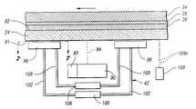
- FIG. 3is a sectional view taken through a glass sheet substrate which has coated layers thereon to be scribed to provide the photovoltaic panel.
- FIG. 4is a sectional view similar to FIG. 3 illustrating the panel after first and second scribes have been made.
- FIG. 5is a sectional view similar to FIG. 4 illustrating the panel at a later stage after a third scribe has been made.
- FIG. 6is a schematic view that illustrates the manner in which the scribing is performed.
- FIG. 7is a view taken in the direction of line 7 — 7 in FIG. 6 to illustrate the construction of positioners utilized to locate the glass sheet substrate during the scribing.
- FIG. 8is a side elevational view illustrating the laser scribing stations, each of which has a right loading end, a center laser scribing module, and a left unloading end.
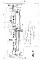
- FIG. 9is a top plan view taken at an enlarged scale along the direction of line 9 — 9 in FIG. 8 to illustrate the laser scribing module.
- FIG. 10is a side elevational view taken along the direction of line 10 — 10 in FIG. 9 to illustrate the laser scribing module at an enlarged scale from that shown in FIG. 8 .
- FIG. 11is a schematic view illustrating the manner in which overlapping ablations through a coating on the substrate perform laser scribing.
- FIG. 12is a view illustrating one way in which the laser scribing proceeds by conveying indexes with the laser scribing performed as the coated glass sheet substrate is held stationary.
- FIG. 13is a view of another way in which the laser scribing proceeds by continuously moving the coated glass sheet substrate and moving the laser beam angularly along the direction of conveyance.
- a system 20includes certain illustrated stations utilized in manufacturing of a photovoltaic panel 22 .
- the panel 22is manufactured using a glass sheet substrate 24 which is shown in FIG. 3 as having one surface coated with a tin oxide layer 26 .
- a cadmium sulfide layer 28about 3000 angstroms thick is deposited at a first station 30 .
- the manufacturingproceeds as the glass sheet substrate is conveyed along a direction of conveyance illustrated by arrow C to a second station 32 where a cadmium telluride layer 34 about 3 microns thick is deposited prior to movement through treating stations 36 and 38 .
- pulsed laser scribing apparatus 42 aAfter subsequent conveyance of the substrate to a first scribing station 40 , pulsed laser scribing apparatus 42 a provides scribing of a first set of scribes 44 , in a manner performed in accordance with the present invention as is hereinafter more fully described, through the tin oxide layer 26 , the cadmium sulfide layer 28 and the cadmium telluride layer 34 .
- the substrateis then conveyed to a station 46 where the first set of scribes 44 are filled with a dielectric material 48 , whereupon the substrate is conveyed to a second scribing station 50 where pulsed laser scribing apparatus 42 b constructed in accordance with the invention operates at a lower power level than the first scribing station to provide scribing of a second set of scribes 52 through the cadmium sulfide layer 28 and the cadmium telluride layer 34 without scribing the tin oxide layer 26 .
- the substrateis then conveyed to a coating station 54 where an electrically conductive back contact layer 56 (FIG.
- scribing apparatus 42 cconstructed in accordance with this invention operates at a lower power level than the second scribing station to provide a third set of scribes 62 through the back contact layer 56 in order to provide separate cells 64 that are electrically connected to each other in series.
- Electrical connectors 65 shown in FIG. 2provide electrical connection of the panel for use.
- the deposition of the cadmium sulfide at station 30 illustrated in FIG. 1 and the deposition of the cadmium telluride at station 32may be performed in accordance with the disclosures of U.S. Pat. No. 5,248,349 Foote et al., U.S. Pat. No. 5,372,646 Foote et al., U.S. Pat. No. 5,470,397 Foote et al., U.S. Pat. No. 5,536,333 Foote et al., U.S. Pat. No. 5,934,163 Powell et al., and U.S. Pat. No. 6,037,241 Powell et al., the entire disclosures of which are hereby incorporated by reference.
- the photovoltaic panel 22 shown in FIG. 2has an elongated shape with a width of about 60 centimeters (600 millimeters) between its opposite sides 66 and a length of about 120 centimeters between its opposite ends 68 . Furthermore, the scribing described above provides 115 of the cells 64 such that the available space for each cell including the associated scribes is just slightly more than one centimeter. Each set of scribes for providing the 115 cells of the panel thus has a total length of about 69,000 millimeters. In order to perform economical manufacturing where the panels can be made in about a minute or so, the laser apparatus must have a scribing speed of about 1000 millimeters per second or greater.
- the scribing apparatus of the inventionas is hereinafter more fully described has a scribe speed of 2000 to 3000 millimeters per second to allow for transfer time between stations. While it is possible to utilize a single laser apparatus to do each set of scribes, provision of the laser scribing apparatus 42 a , 42 b , and 42 c at each of the three scribing stations as illustrated in FIG. 1 provides a higher rate of operation and a consequently more cost efficient product.
- This laser scribing apparatus 42is illustrated in FIGS. 6-10 and as specifically illustrated in FIG. 8 includes a right loading end 70 , a left unloading end 72 , and a central laser scribing module 74 .
- the coated glass sheet substrate to be scribedis conveyed in a vertically extending orientation toward the left from the loading end 70 to the laser scribing module 74 for the laser scribing and is subsequently conveyed toward the left to the unloading end 72 in preparation for delivery to the next station.
- the conveyance from the loading end 70is provided on a loading cart 76 and the glass sheet is received by a laser scribing conveyor 78 best shown in FIG. 10 for accurately controlled conveyance during the laser scribing operation.
- the scribed glass sheet substrateis delivered from the laser scribing conveyor 78 to an unloading cart 80 of the unloading station 72 shown in FIG. 8 .
- the conveyor 78conveys the glass sheet substrate 24 which as illustrated in FIG.
- the scribingis performed by directing a laser beam through the glass sheet substrate 24 from its uncoated surface 81 to its coated surface 82 and through to the different layers for the scribing, with the layers scribed being controlled by the power level of the laser for each of the scribes.
- the laser scribing apparatus 42includes a laser source 83 that provides the pulsed laser beam 84 with a wavelength at a near-infrared fundamental frequency and having a pulse frequency in the range of 50 to 100 kilohertz and a pulse duration in the range of 8 to 70 nanoseconds.
- the specific laser source 83 utilizedis a diode-pumped, Q-switched, neodymium-doped, yttrium vanadate laser source providing a pulsed laser beam with a wavelength at its near-infrared fundamental frequency of 1064 nanometers and operating at a pulse frequency in the range of 50 to 100 kilohertz with the pulse duration in the range of 8 to 70 nanoseconds.
- the pulsed laser beamis reflected by mirrors 86 and 88 to an XYZ galvanometer controlled mirror system collectively indicated by 90 that directs the laser beam to perform the scribing.
- the XYZ galvanometer controlled mirror system 90includes a galvanometer controlled focuser 92 that moves a lens horizontally to control the focal length of the beam in the Z direction and a galvanometer controlled dual mirror assembly 94 that directs the beam in the XY directions so as to thereby collectively provide XYZ control.
- the scribing as shown in FIG. 11is performed with the ablations 95 overlapping each other.
- An overlap of 50%provides a generally uniform scribe width and a fast scribe speed.
- the ablations 95thus provide a scribe such as the first scribe 44 illustrated in FIG. 11, and the second and third scribes are also provided in the same way.
- the laser scribing apparatus 42includes gas pressure and vacuum positioners 96 that maintain the glass sheet substrate planar at its uncoated surface 81 and position the substrate laterally with respect to the direction of conveyance so the focused pulsed laser beam has its focus in the Z direction at the layer or layers being scribed.
- These positioners 96are located in vertically extending sets both upstream and downstream of the location where the laser beam 84 passes through the glass sheet substrate to provide the laser scribing. More specifically as illustrated in FIG. 10, there are five of the positioners 96 upstream of the scribing location and five of the positioners downstream of the scribing location. As illustrated in FIGS.
- each of the positioners 96has a central location 98 to which a vacuum is applied from a vacuum source 100 through an associated conduit 102 .
- An annular porous member 104 of each positioners 96extends around the central location 98 and receives pressurized gas from a gas source 106 through an associated conduit 108 .
- the positioners 96position the uncoated glass sheet surface 81 within about 4-6 microns so as to provide an accurate location for the laser beam focusing and the ablations at the layer or layers being scribed.
- laser detectors 109 located upstream from the scribing locationprovide laser detection beams 109 a (FIG. 6) that are reflected back from the uncoated glass surface 81 to detect the exact position of the glass substrate and through connection to the focuser of the galvanometer mirror system 90 focuses the pulsed scribing laser beam 84 in response to the position detected throughout the range of movement and scribing of the scribing laser beam.
- This detectionaccommodates for any nonplanarity of the glass sheet substrate such as roller waves formed when the glass is manufactured.
- the laser scribing station conveyorprovides a conveying index 110 between each laser scribe 112 during which the coated substrate is held stationary such that the laser beam moves vertically to perform the scribing, after first having been adjusted horizontally to provide the proper spacing between the previously formed adjacent scribe.
- FIG. 12illustrates two different ways in which the laser scribing can be performed.
- the laser scribing station conveyorprovides a conveying index 110 between each laser scribe 112 during which the coated substrate is held stationary such that the laser beam moves vertically to perform the scribing, after first having been adjusted horizontally to provide the proper spacing between the previously formed adjacent scribe.
- the coated glass sheet substrateit is also possible for the coated glass sheet substrate to be continuously conveyed along the direction of conveyance C and the path of the laser scribes 114 is then angular both along the direction of conveyance and with respect to a true vertical direction, and after the completion of each scribe, there is a reset motion 115 of the galvanometer controlled mirror system such that the complete pass as illustrated has a generally bow tie configuration.
- the two upper corners of the coated glass sheet substrateare laser marked with respective fiducials which are detected by a pair of cameras 116 so as to provide a signal for accurate location of the panel and the spacing between the fiducials so that the scribing can be accurately located. This allows adjustment as necessary for thermal expansion or contraction and for different spacings between the fiducials on different substrates.
- each substratecan be provided with a bar code that is sensed by a bar code reader 118 shown in FIG. 9 so as to provide identification of each particular substrate being scribed.
- the apparatusincludes an exhaust hood 120 that receives the exhaust from the coated side of the substrate being scribed. To insure that the scribing is performed at the proper power level, the galvanometer controlled mirror 90 can periodically reflect the laser beam as shown at 84 a to a power meter 122 whose sensed power can then be utilized to provide any necessary adjustment of the power level from the pulsed laser source 83 .
- the average power levels of the lasersare respectively about 20 watts, 8 to 9 watts, and 4 to 5 watts.
Landscapes
- Physics & Mathematics (AREA)
- Optics & Photonics (AREA)
- Engineering & Computer Science (AREA)
- Plasma & Fusion (AREA)
- Mechanical Engineering (AREA)
- Chemical & Material Sciences (AREA)
- Life Sciences & Earth Sciences (AREA)
- Chemical Kinetics & Catalysis (AREA)
- General Chemical & Material Sciences (AREA)
- Geochemistry & Mineralogy (AREA)
- Materials Engineering (AREA)
- Organic Chemistry (AREA)
- Toxicology (AREA)
- Health & Medical Sciences (AREA)
- Laser Beam Processing (AREA)
- Re-Forming, After-Treatment, Cutting And Transporting Of Glass Products (AREA)
- Processing Of Stones Or Stones Resemblance Materials (AREA)
- Manufacturing & Machinery (AREA)
Abstract
Description
Claims (11)
Priority Applications (8)
| Application Number | Priority Date | Filing Date | Title |
|---|---|---|---|
| US09/928,203US6559411B2 (en) | 2001-08-10 | 2001-08-10 | Method and apparatus for laser scribing glass sheet substrate coatings |
| JP2003518767AJP4429013B2 (en) | 2001-08-10 | 2002-08-07 | Method and apparatus for laser scribing a glass sheet substrate coating |
| PCT/US2002/024925WO2003013778A1 (en) | 2001-08-10 | 2002-08-07 | Method and apparatus for laser scribing glass sheet substrate coatings |
| EP02768438.0AEP1423229B1 (en) | 2001-08-10 | 2002-08-07 | Method and apparatus for laser scribing glass sheet substrate coatings |
| TW91117978ATW572804B (en) | 2001-08-10 | 2002-08-09 | Method and apparatus for laser scribing glass sheet substrate coatings |
| US10/425,704US6919530B2 (en) | 2001-08-10 | 2003-04-30 | Method and apparatus for laser scribing glass sheet substrate coatings |
| US10/915,736US9457429B2 (en) | 2001-08-10 | 2004-08-11 | Method and apparatus for laser scribing glass sheet substrate coatings |
| JP2009204219AJP5280978B2 (en) | 2001-08-10 | 2009-09-04 | Method and apparatus for laser scribing a glass sheet substrate coating |
Applications Claiming Priority (1)
| Application Number | Priority Date | Filing Date | Title |
|---|---|---|---|
| US09/928,203US6559411B2 (en) | 2001-08-10 | 2001-08-10 | Method and apparatus for laser scribing glass sheet substrate coatings |
Related Child Applications (1)
| Application Number | Title | Priority Date | Filing Date |
|---|---|---|---|
| US10/425,704ContinuationUS6919530B2 (en) | 2001-08-10 | 2003-04-30 | Method and apparatus for laser scribing glass sheet substrate coatings |
Publications (2)
| Publication Number | Publication Date |
|---|---|
| US20030029848A1 US20030029848A1 (en) | 2003-02-13 |
| US6559411B2true US6559411B2 (en) | 2003-05-06 |
Family
ID=25455878
Family Applications (3)
| Application Number | Title | Priority Date | Filing Date |
|---|---|---|---|
| US09/928,203Expired - LifetimeUS6559411B2 (en) | 2001-08-10 | 2001-08-10 | Method and apparatus for laser scribing glass sheet substrate coatings |
| US10/425,704Expired - LifetimeUS6919530B2 (en) | 2001-08-10 | 2003-04-30 | Method and apparatus for laser scribing glass sheet substrate coatings |
| US10/915,736Expired - LifetimeUS9457429B2 (en) | 2001-08-10 | 2004-08-11 | Method and apparatus for laser scribing glass sheet substrate coatings |
Family Applications After (2)
| Application Number | Title | Priority Date | Filing Date |
|---|---|---|---|
| US10/425,704Expired - LifetimeUS6919530B2 (en) | 2001-08-10 | 2003-04-30 | Method and apparatus for laser scribing glass sheet substrate coatings |
| US10/915,736Expired - LifetimeUS9457429B2 (en) | 2001-08-10 | 2004-08-11 | Method and apparatus for laser scribing glass sheet substrate coatings |
Country Status (5)
| Country | Link |
|---|---|
| US (3) | US6559411B2 (en) |
| EP (1) | EP1423229B1 (en) |
| JP (2) | JP4429013B2 (en) |
| TW (1) | TW572804B (en) |
| WO (1) | WO2003013778A1 (en) |
Cited By (87)
| Publication number | Priority date | Publication date | Assignee | Title |
|---|---|---|---|---|
| US20030180983A1 (en)* | 2002-01-07 | 2003-09-25 | Oswald Robert S. | Method of manufacturing thin film photovoltaic modules |
| US20050224475A1 (en)* | 2004-04-13 | 2005-10-13 | Disco Corporation | Laser beam processing machine |
| US20050255238A1 (en)* | 2004-05-12 | 2005-11-17 | Myer Charles N | Pulsed heating process for curing substrates with near infrared radiation |
| US20070232057A1 (en)* | 2006-03-31 | 2007-10-04 | Applied Materials, Inc. | Method for forming thin film photovoltaic interconnects using self-aligned process |
| US20070227578A1 (en)* | 2006-03-31 | 2007-10-04 | Applied Materials, Inc. | Method for patterning a photovoltaic device comprising CIGS material using an etch process |
| US20070238285A1 (en)* | 2006-03-31 | 2007-10-11 | Applied Materials, Inc. | Method for making an improved thin film solar cell interconnect using etch and deposition process |
| US20070235430A1 (en)* | 2006-04-10 | 2007-10-11 | Disco Corporation | Laser beam processing machine |
| US20080105303A1 (en)* | 2003-01-03 | 2008-05-08 | Bp Corporation North America Inc. | Method and Manufacturing Thin Film Photovoltaic Modules |
| DE102007015767A1 (en)* | 2007-03-30 | 2008-10-02 | Oerlikon Optics UK Ltd., Yarnton | Method for laser scribing of solar cells |
| US20080263877A1 (en)* | 2007-04-24 | 2008-10-30 | Newport Corporation | Laser scribing system and method of use |
| US20100055901A1 (en)* | 2008-08-26 | 2010-03-04 | Applied Materials, Inc. | Laser material removal methods and apparatus |
| WO2010006589A3 (en)* | 2008-07-17 | 2010-03-11 | Feraric Peter | Laser scribing system for structuring substrates for thin-layer solar modules |
| US20100065099A1 (en)* | 2008-09-18 | 2010-03-18 | General Electric Company | Monolithically connected photovoltaic devices on flexible substrates |
| DE102009020365A1 (en) | 2009-05-07 | 2010-11-11 | Jenoptik Automatisierungstechnik Gmbh | Process for the production of thin-film solar cell modules with a predetermined transparency |
| US20100298964A1 (en)* | 2009-05-21 | 2010-11-25 | Electro Scientific Industries, Inc. | Apparatus and method for non-contact sensing of transparent articles |
| DE102009031233A1 (en) | 2009-06-26 | 2010-12-30 | Jenoptik Automatisierungstechnik Gmbh | Device for structuring thin-film solar cell modules by means of laser |
| US20110021008A1 (en)* | 2009-07-22 | 2011-01-27 | Applied Materials, Inc. | Directional Solid Phase Crystallization of Thin Amorphous Silicon for Solar Cell Applications |
| US20110049764A1 (en)* | 2009-09-02 | 2011-03-03 | Lee Hyun-Chul | Substrate cutting apparatus and method for cutting substrate using the same |
| US20110065227A1 (en)* | 2009-09-15 | 2011-03-17 | Applied Materials, Inc. | Common laser module for a photovoltaic production line |
| US20120021536A1 (en)* | 2010-07-23 | 2012-01-26 | Primestar Solar, Inc. | Method and system for application of an insulating dielectric material to photovoltaic module substrates |
| US8164818B2 (en) | 2010-11-08 | 2012-04-24 | Soladigm, Inc. | Electrochromic window fabrication methods |
| CN102554472A (en)* | 2010-10-12 | 2012-07-11 | 上方能源技术(杭州)有限公司 | Lineation method and apparatus for thin-film solar cell |
| US8228592B2 (en) | 2010-04-30 | 2012-07-24 | Soladigm, Inc. | Electrochromic devices |
| US8243357B2 (en) | 2009-03-31 | 2012-08-14 | Soladigm, Inc. | Fabrication of low defectivity electrochromic devices |
| DE102012103243A1 (en)* | 2011-04-19 | 2012-10-25 | Primestar Solar, Inc. | Method for temporally varying the laser intensity during scoring of a photovoltaic device |
| US8300298B2 (en) | 2010-04-30 | 2012-10-30 | Soladigm, Inc. | Electrochromic devices |
| US8418418B2 (en) | 2009-04-29 | 2013-04-16 | 3Form, Inc. | Architectural panels with organic photovoltaic interlayers and methods of forming the same |
| US20130122687A1 (en)* | 2011-11-16 | 2013-05-16 | Applied Materials, Inc. | Laser scribing systems, apparatus, and methods |
| US8643933B2 (en) | 2011-12-14 | 2014-02-04 | View, Inc. | Connectors for smart windows |
| US8677783B2 (en) | 2011-11-28 | 2014-03-25 | Corning Incorporated | Method for low energy separation of a glass ribbon |
| US8711465B2 (en) | 2010-12-08 | 2014-04-29 | View, Inc. | Spacers for insulated glass units |
| US8764950B2 (en) | 2010-04-30 | 2014-07-01 | View, Inc. | Electrochromic devices |
| US8764951B2 (en) | 2010-04-30 | 2014-07-01 | View, Inc. | Electrochromic devices |
| US9261751B2 (en) | 2010-04-30 | 2016-02-16 | View, Inc. | Electrochromic devices |
| US9341909B2 (en) | 2008-06-25 | 2016-05-17 | View, Inc. | Multi-pane dynamic window and method for making same |
| US9341912B2 (en) | 2012-03-13 | 2016-05-17 | View, Inc. | Multi-zone EC windows |
| US9442339B2 (en) | 2010-12-08 | 2016-09-13 | View, Inc. | Spacers and connectors for insulated glass units |
| US9454053B2 (en) | 2011-12-12 | 2016-09-27 | View, Inc. | Thin-film devices and fabrication |
| US9482922B2 (en) | 2011-03-16 | 2016-11-01 | View, Inc. | Multipurpose controller for multistate windows |
| US9703167B2 (en) | 2010-11-08 | 2017-07-11 | View, Inc. | Electrochromic window fabrication methods |
| US9759975B2 (en) | 2010-04-30 | 2017-09-12 | View, Inc. | Electrochromic devices |
| US9782949B2 (en) | 2008-05-30 | 2017-10-10 | Corning Incorporated | Glass laminated articles and layered articles |
| US20170373262A1 (en)* | 2014-12-23 | 2017-12-28 | Stichting Energieonderzoek Centrum Nederland | Method of making a current collecting grid for solar cells |
| US10156762B2 (en) | 2009-03-31 | 2018-12-18 | View, Inc. | Counter electrode for electrochromic devices |
| US10175549B2 (en) | 2011-03-16 | 2019-01-08 | View, Inc. | Connectors for smart windows |
| US10180606B2 (en) | 2010-12-08 | 2019-01-15 | View, Inc. | Connectors for smart windows |
| US10228601B2 (en) | 2014-11-26 | 2019-03-12 | View, Inc. | Counter electrode for electrochromic devices |
| US10261381B2 (en) | 2009-03-31 | 2019-04-16 | View, Inc. | Fabrication of low defectivity electrochromic devices |
| US10288971B2 (en) | 2012-08-23 | 2019-05-14 | View, Inc. | Photonic-powered EC devices |
| US10303035B2 (en) | 2009-12-22 | 2019-05-28 | View, Inc. | Self-contained EC IGU |
| US10345671B2 (en) | 2014-09-05 | 2019-07-09 | View, Inc. | Counter electrode for electrochromic devices |
| US10429712B2 (en) | 2012-04-20 | 2019-10-01 | View, Inc. | Angled bus bar |
| US10481458B2 (en) | 2013-06-18 | 2019-11-19 | View, Inc. | Electrochromic devices on non-rectangular shapes |
| US10591795B2 (en) | 2009-03-31 | 2020-03-17 | View, Inc. | Counter electrode for electrochromic devices |
| US10606142B2 (en) | 2011-12-12 | 2020-03-31 | View, Inc. | Thin-film devices and fabrication |
| US10739658B2 (en) | 2011-12-12 | 2020-08-11 | View, Inc. | Electrochromic laminates |
| US10852613B2 (en) | 2009-03-31 | 2020-12-01 | View, Inc. | Counter electrode material for electrochromic devices |
| US10975612B2 (en) | 2014-12-15 | 2021-04-13 | View, Inc. | Seals for electrochromic windows |
| US11008250B2 (en) | 2014-06-25 | 2021-05-18 | Nkt Photonics A/S | Laser processing |
| US11048137B2 (en) | 2011-12-12 | 2021-06-29 | View, Inc. | Thin-film devices and fabrication |
| WO2021165064A1 (en) | 2020-02-18 | 2021-08-26 | Agc Glass Europe | Apparatus for removing at least one portion of at least one coating system presenting a multi-glazed window and associated method |
| US11187954B2 (en) | 2009-03-31 | 2021-11-30 | View, Inc. | Electrochromic cathode materials |
| WO2021239603A1 (en) | 2020-05-26 | 2021-12-02 | Agc Glass Europe | Apparatus and method for removing at least one portion of at least one coating system present in a multi-glazed window mounted on a stationary or mobile object |
| WO2021239597A1 (en) | 2020-05-26 | 2021-12-02 | Agc Glass Europe | Apparatus and method for removing at least one portion of at least one coating system present in a multi-glazed window mounted on a stationary or mobile object |
| US11255120B2 (en) | 2012-05-25 | 2022-02-22 | View, Inc. | Tester and electrical connectors for insulated glass units |
| US11314139B2 (en) | 2009-12-22 | 2022-04-26 | View, Inc. | Self-contained EC IGU |
| US11320713B2 (en) | 2017-02-16 | 2022-05-03 | View, Inc. | Solar power dynamic glass for heating and cooling buildings |
| WO2022112521A2 (en) | 2020-11-30 | 2022-06-02 | Agc Glass Europe | Laser apparatus comprising a closing means and associated method and use |
| WO2022112529A2 (en) | 2020-11-30 | 2022-06-02 | Agc Glass Europe | Laser apparatus mounted on a window mounted in situ comprising a skirt and associated method and use |
| WO2022112530A2 (en) | 2020-11-30 | 2022-06-02 | Agc Glass Europe | Method of calibrating a focal point of a laser apparatus mounted on a window mounted in situ |
| WO2022112532A2 (en) | 2020-11-30 | 2022-06-02 | Agc Glass Europe | Decoating apparatus and associated method to decoat at least partially a portion of a coating system presents on a surface of a window mounted in situ |
| US11635666B2 (en) | 2012-03-13 | 2023-04-25 | View, Inc | Methods of controlling multi-zone tintable windows |
| US11719039B2 (en) | 2011-12-14 | 2023-08-08 | View, Inc. | Connectors for smart windows |
| US11891327B2 (en) | 2014-05-02 | 2024-02-06 | View, Inc. | Fabrication of low defectivity electrochromic devices |
| WO2024115699A1 (en) | 2022-12-02 | 2024-06-06 | Agc Glass Europe | Apparatus and associated methods for removing at least one portion of at least one coating system present in a multi-glazed window mounted on a stationary or mobile object |
| US12043890B2 (en) | 2009-03-31 | 2024-07-23 | View, Inc. | Electrochromic devices |
| US12153320B2 (en) | 2012-03-13 | 2024-11-26 | View, Inc. | Multi-zone EC windows |
| WO2024251595A1 (en) | 2023-06-08 | 2024-12-12 | Agc Glass Europe | Decoating apparatus and associated methods for decoating a portion of a coating on a window |
| WO2024251621A1 (en) | 2023-06-08 | 2024-12-12 | Agc Glass Europe | Decoating apparatus and associated methods for decoating a portion of a coating on a window |
| WO2024251624A1 (en) | 2023-06-08 | 2024-12-12 | Agc Glass Europe | Decoating apparatus and associated methods for decoating a portion of a coating on a window |
| WO2024251618A1 (en) | 2023-06-08 | 2024-12-12 | Agc Glass Europe | System comprising a decoating apparatus and associated methods for decoating a portion of a coating on a window |
| WO2025046119A1 (en) | 2023-08-30 | 2025-03-06 | Agc Glass Europe | Decoating apparatus and associated methods and use |
| WO2025068129A1 (en) | 2023-09-25 | 2025-04-03 | Agc Glass Europe | System comprising a decoating apparatus and associated methods and use |
| US12321075B2 (en) | 2011-12-12 | 2025-06-03 | View Operating Corporation | Electrochromic laminates |
| US12353109B2 (en) | 2009-12-22 | 2025-07-08 | View Operating Corporation | Electrochromic cathode materials |
| US12429742B2 (en) | 2012-03-13 | 2025-09-30 | View Operating Corporation | Methods of controlling multi-zone tintable windows |
| US12443085B2 (en) | 2024-03-20 | 2025-10-14 | View Operating Corporation | Counter electrode for electrochromic devices |
Families Citing this family (70)
| Publication number | Priority date | Publication date | Assignee | Title |
|---|---|---|---|---|
| RU2254299C1 (en)* | 2003-11-05 | 2005-06-20 | Алексеев Андрей Михайлович | Method of separation of solid transparent laminas with the light-emitting or microelectronic structures |
| KR100626554B1 (en)* | 2004-05-11 | 2006-09-21 | 주식회사 탑 엔지니어링 | Non-metal cutting device and cutting depth control method when cutting |
| US20050272175A1 (en)* | 2004-06-02 | 2005-12-08 | Johannes Meier | Laser structuring for manufacture of thin film silicon solar cells |
| GB2439962B (en)* | 2006-06-14 | 2008-09-24 | Exitech Ltd | Process and apparatus for laser scribing |
| DE102006033296A1 (en)* | 2006-07-17 | 2008-01-31 | Manz Automation Ag | Plant for structuring solar modules |
| CN101134263A (en)* | 2006-09-01 | 2008-03-05 | 富士迈半导体精密工业(上海)有限公司 | Laser processing method and corresponding laser processing device |
| GB0622232D0 (en)* | 2006-11-08 | 2006-12-20 | Rumsby Philip T | Method and apparatus for laser beam alignment for solar panel scribing |
| JP2010518604A (en) | 2007-02-01 | 2010-05-27 | ウィラード アンド ケルシー ソーラー グループ, エルエルシー | Glass sheet semiconductor coating system and method and resulting product |
| US8853527B2 (en) | 2007-02-16 | 2014-10-07 | Nanogram Corporation | Solar cell structures, photovoltaic panels and corresponding processes |
| GB0802289D0 (en)* | 2008-02-07 | 2008-03-12 | Rumsby Philip T | Method and appartus for making a partially transparent solar panel |
| TW201006600A (en)* | 2008-04-10 | 2010-02-16 | Applied Materials Inc | Laser-scribing platform and hybrid writing strategy |
| CN101990481A (en)* | 2008-04-10 | 2011-03-23 | 应用材料股份有限公司 | Laser-scribing platform |
| US20090321399A1 (en)* | 2008-04-11 | 2009-12-31 | Applied Materials, Inc. | Dynamic scribe alignment for laser scribing, welding or any patterning system |
| WO2009126910A2 (en)* | 2008-04-11 | 2009-10-15 | Applied Materials, Inc. | Laser scribe inspection methods and systems |
| US20090314752A1 (en)* | 2008-05-14 | 2009-12-24 | Applied Materials, Inc. | In-situ monitoring for laser ablation |
| DE102008032555B3 (en)* | 2008-07-10 | 2010-01-21 | Innolas Systems Gmbh | Structuring device for the structuring of plate-shaped elements, in particular of thin-film solar modules, corresponding structuring method and use thereof |
| JP2010087041A (en)* | 2008-09-29 | 2010-04-15 | Ulvac Japan Ltd | Method of removing thin film by laser beam, and method of manufacturing thin-film solar cell panel |
| US8450641B2 (en)* | 2008-10-10 | 2013-05-28 | Ipg Microsystems Llc | Laser machining systems and methods with moving laser scanning stage(s) providing force cancellation |
| WO2010059595A2 (en)* | 2008-11-19 | 2010-05-27 | Applied Materials, Inc. | Laser-scribing tool architecture |
| JPWO2010071201A1 (en)* | 2008-12-19 | 2012-05-31 | シャープ株式会社 | Film removal method, photoelectric conversion device manufacturing method, photoelectric conversion device, and film removal device |
| US20100212358A1 (en)* | 2009-02-26 | 2010-08-26 | Applied Materials, Inc. | Glass substrate orientation inspection methods and systems for photo voltaics production |
| US8333843B2 (en)* | 2009-04-16 | 2012-12-18 | Applied Materials, Inc. | Process to remove metal contamination on a glass substrate |
| US20100269853A1 (en)* | 2009-04-27 | 2010-10-28 | Applied Materials, Inc. | Debris-extraction exhaust system |
| US20100294352A1 (en)* | 2009-05-20 | 2010-11-25 | Uma Srinivasan | Metal patterning for electrically conductive structures based on alloy formation |
| US20100294349A1 (en)* | 2009-05-20 | 2010-11-25 | Uma Srinivasan | Back contact solar cells with effective and efficient designs and corresponding patterning processes |
| WO2010144778A2 (en)* | 2009-06-12 | 2010-12-16 | Applied Materials, Inc. | Methods and systems for laser-scribed line alignment |
| US20100330711A1 (en)* | 2009-06-26 | 2010-12-30 | Applied Materials, Inc. | Method and apparatus for inspecting scribes in solar modules |
| US20110005458A1 (en)* | 2009-07-13 | 2011-01-13 | Applied Materials, Inc. | Method and apparatus for improving scribe accuracy in solar cell modules |
| US20110008947A1 (en)* | 2009-07-13 | 2011-01-13 | Applied Materials, Inc. | Apparatus and method for performing multifunction laser processes |
| US20110198322A1 (en)* | 2009-08-06 | 2011-08-18 | Applied Materials, Inc. | In-line metrology methods and systems for solar cell fabrication |
| US8129658B2 (en)* | 2009-08-06 | 2012-03-06 | Applied Materials, Inc. | Systems for thin film laser scribing devices |
| US20110139758A1 (en)* | 2009-08-06 | 2011-06-16 | Applied Materials, Inc. | Latitudinal iso-line scribe, stitching, and simplified laser and scanner controls |
| WO2011017572A2 (en)* | 2009-08-06 | 2011-02-10 | Applied Materials, Inc. | Laser modules and processes for thin film solar panel laser scribing |
| US8932510B2 (en)* | 2009-08-28 | 2015-01-13 | Corning Incorporated | Methods for laser cutting glass substrates |
| EP2480342B1 (en)* | 2009-09-22 | 2021-02-24 | First Solar, Inc | System and method for tracking and removing coating from an edge of a substrate |
| WO2011037922A1 (en)* | 2009-09-22 | 2011-03-31 | First Solar, Inc. | System and method for removing coating from an edge of a substrate |
| KR101144570B1 (en)* | 2009-09-30 | 2012-05-11 | 엘지이노텍 주식회사 | Solar cell and method of fabircating the same |
| WO2011043734A1 (en)* | 2009-10-07 | 2011-04-14 | Manufacturing Integration Technology Ltd | Laser scribing of thin-film solar cell panel |
| US8865569B2 (en) | 2009-10-22 | 2014-10-21 | M-Solv Ltd. | Method and apparatus for dividing thin film device into separate cells |
| GB2474665B (en) | 2009-10-22 | 2011-10-12 | M Solv Ltd | Method and apparatus for dividing thin film device into separate cells |
| US20110139755A1 (en)* | 2009-11-03 | 2011-06-16 | Applied Materials, Inc. | Multi-wavelength laser-scribing tool |
| US8946590B2 (en) | 2009-11-30 | 2015-02-03 | Corning Incorporated | Methods for laser scribing and separating glass substrates |
| US20110155707A1 (en)* | 2009-12-31 | 2011-06-30 | Du Pont Apollo Limited | Laser scribing apparatus and process for solar panel |
| US8928105B2 (en) | 2010-05-28 | 2015-01-06 | Flisom Ag | Method and apparatus for thin film module with dotted interconnects and vias |
| US8247682B2 (en)* | 2010-06-29 | 2012-08-21 | Primestar Solar, Inc. | Metallic gridlines as front contacts of a cadmium telluride based thin film photovoltaic device |
| DE202010013161U1 (en) | 2010-07-08 | 2011-03-31 | Oerlikon Solar Ag, Trübbach | Laser processing with several beams and suitable laser optics head |
| TWI513670B (en) | 2010-08-31 | 2015-12-21 | Corning Inc | Methods of separating strengthened glass substrates |
| GB2483922B (en)* | 2010-09-25 | 2013-11-20 | M Solv Ltd | Method and apparatus for dividing thin film device into separate cells |
| US20120074109A1 (en)* | 2010-09-29 | 2012-03-29 | General Electric Company | Method and system for scribing a multilayer panel |
| US8912083B2 (en) | 2011-01-31 | 2014-12-16 | Nanogram Corporation | Silicon substrates with doped surface contacts formed from doped silicon inks and corresponding processes |
| DE102011000673A1 (en) | 2011-02-11 | 2012-08-16 | Lpkf Laser & Electronics Ag | Device, useful for introducing linear recesses in a substrate by means of a laser beam, comprises at least one deflection unit movable along a tracking axis parallel to a transport axis, for deflecting several laser beams on substrate |
| GB2492971B (en) | 2011-07-15 | 2013-09-18 | M Solv Ltd | Method and apparatus for dividing thin film device into separate cells |
| CN102299209B (en)* | 2011-09-13 | 2013-04-10 | 上海太阳能电池研究与发展中心 | Method for manufacturing integrated film solar cell assembly |
| US8377737B1 (en) | 2011-11-30 | 2013-02-19 | Primestar Solar, Inc. | Methods of short wavelength laser scribing of a thin film photovoltaic device |
| US11060183B2 (en)* | 2012-03-23 | 2021-07-13 | Hzo, Inc. | Apparatuses, systems and methods for applying protective coatings to electronic device assemblies |
| JP2013143563A (en) | 2012-01-10 | 2013-07-22 | Hzo Inc | Systems for assembling electronic devices with internal moisture-resistant coatings |
| US9938180B2 (en) | 2012-06-05 | 2018-04-10 | Corning Incorporated | Methods of cutting glass using a laser |
| US9610653B2 (en) | 2012-09-21 | 2017-04-04 | Electro Scientific Industries, Inc. | Method and apparatus for separation of workpieces and articles produced thereby |
| CN103121365B (en)* | 2012-12-20 | 2014-02-12 | 苏州菱欧自动化设备有限公司 | Laser marking device |
| TWI555599B (en)* | 2013-02-25 | 2016-11-01 | 先進科技新加坡有限公司 | Method for performing beam characterization in a laser scribe device, and laser scribe device capable of performing the same |
| US10096731B2 (en) | 2014-01-31 | 2018-10-09 | Flisom Ag | Method for thin-film via segments in photovoltaic device |
| US9899546B2 (en) | 2014-12-05 | 2018-02-20 | Tesla, Inc. | Photovoltaic cells with electrodes adapted to house conductive paste |
| US20160172243A1 (en)* | 2014-12-11 | 2016-06-16 | Nxp B.V. | Wafer material removal |
| WO2016096435A1 (en)* | 2014-12-18 | 2016-06-23 | Saint-Gobain Glass France | Method for producing a composite pane having a corrosion-protected functional coating |
| ITUB20152328A1 (en)* | 2015-07-20 | 2017-01-20 | Tapematic Spa | METHOD AND MACHINE FOR DECORATING OBJECTS OF SMALL DIMENSIONS AND OBTAINABLE PRODUCT |
| FR3070977B1 (en)* | 2017-09-14 | 2020-05-22 | Dalloz Creations | NEW PROCESS FOR PARTIAL MIRRORING OF GLASSES, AND LENSES OBTAINED THANKS TO THE PROCESS |
| FR3105044B1 (en)* | 2019-12-20 | 2022-08-12 | Saint Gobain | SUBSTRATE TREATMENT DEVICE |
| JP7425966B2 (en)* | 2020-03-12 | 2024-02-01 | 日本電気硝子株式会社 | Glass plate manufacturing method and its manufacturing device |
| CN112768556A (en)* | 2020-12-31 | 2021-05-07 | 中国建材国际工程集团有限公司 | Manufacturing process of CdTe solar cell |
| JP2024510506A (en) | 2021-03-19 | 2024-03-07 | ファースト・ソーラー・インコーポレーテッド | Photovoltaic devices with conductive layer interconnects |
Citations (12)
| Publication number | Priority date | Publication date | Assignee | Title |
|---|---|---|---|---|
| US4292092A (en) | 1980-06-02 | 1981-09-29 | Rca Corporation | Laser processing technique for fabricating series-connected and tandem junction series-connected solar cells into a solar battery |
| US4568409A (en) | 1983-11-17 | 1986-02-04 | Chronar Corp. | Precision marking of layers |
| US4603470A (en) | 1983-07-13 | 1986-08-05 | Semiconductor Energy Lab. Co. | Method of making plurality of series connected solar cells using multiple groove forming processes |
| US4689874A (en) | 1985-05-16 | 1987-09-01 | Fuji Electric Company, Ltd. | Process for fabricating a thin-film solar battery |
| US4854974A (en) | 1987-06-29 | 1989-08-08 | Solarex Corporation | Electrical contacts for a thin-film semiconductor device |
| US4892592A (en) | 1987-03-26 | 1990-01-09 | Solarex Corporation | Thin film semiconductor solar cell array and method of making |
| US5248349A (en) | 1992-05-12 | 1993-09-28 | Solar Cells, Inc. | Process for making photovoltaic devices and resultant product |
| US5296674A (en) | 1991-10-07 | 1994-03-22 | Siemens Aktiengesellschaft | Laser processing method for a thin-film structure |
| US5593901A (en) | 1989-09-08 | 1997-01-14 | Amoco/Enron Solar | Monolithic series and parallel connected photovoltaic module |
| US5934163A (en) | 1997-01-14 | 1999-08-10 | Vorum Research Corporation | Carving blank and mandrel for mounting same in a carving machine |
| US5956572A (en) | 1996-08-26 | 1999-09-21 | Sharp Kabushiki Kaisha | Method of fabricating integrated thin film solar cells |
| US6037241A (en) | 1998-02-19 | 2000-03-14 | First Solar, Llc | Apparatus and method for depositing a semiconductor material |
Family Cites Families (20)
| Publication number | Priority date | Publication date | Assignee | Title |
|---|---|---|---|---|
| US4645547A (en)* | 1982-10-20 | 1987-02-24 | Westinghouse Electric Corp. | Loss ferromagnetic materials and methods of improvement |
| US4535218A (en)* | 1982-10-20 | 1985-08-13 | Westinghouse Electric Corp. | Laser scribing apparatus and process for using |
| JPS59107579A (en)* | 1982-12-11 | 1984-06-21 | Semiconductor Energy Lab Co Ltd | Method for manufacturing photoelectric conversion device |
| JPS6018973A (en)* | 1983-07-13 | 1985-01-31 | Semiconductor Energy Lab Co Ltd | Photoelectric conversion semiconductor device |
| US4598039A (en)* | 1984-07-02 | 1986-07-01 | At&T Bell Laboratories | Formation of features in optical material |
| JPS6240986A (en)* | 1985-08-20 | 1987-02-21 | Fuji Electric Corp Res & Dev Ltd | Laser processing method |
| US4752455A (en)* | 1986-05-27 | 1988-06-21 | Kms Fusion, Inc. | Pulsed laser microfabrication |
| US4705698A (en)* | 1986-10-27 | 1987-11-10 | Chronar Corporation | Isolation of semiconductor contacts |
| US4929092A (en)* | 1987-06-12 | 1990-05-29 | Mitsubishi Jukogyo Kabushiki Kaisha | Resistance temperature detector |
| JP2587972B2 (en)* | 1988-01-06 | 1997-03-05 | 株式会社半導体エネルギー研究所 | Thin film structure |
| EP0454620B1 (en)* | 1990-04-23 | 1993-11-10 | Bystronic Laser AG | Method and device for cutting of flat materials |
| DE4034089A1 (en)* | 1990-10-26 | 1992-04-30 | Pierburg Gmbh | METHOD FOR CONTROLLING AN ELECTROPNEUMATIC ACTUATOR |
| JP3165304B2 (en)* | 1992-12-04 | 2001-05-14 | 株式会社半導体エネルギー研究所 | Semiconductor device manufacturing method and semiconductor processing apparatus |
| CN100367461C (en)* | 1993-11-05 | 2008-02-06 | 株式会社半导体能源研究所 | Method for manufacturing thin film transistor and electronic device |
| US5658474A (en)* | 1994-12-16 | 1997-08-19 | Alza Corporation | Method and apparatus for forming dispenser delivery ports |
| JP2000052071A (en)* | 1998-08-04 | 2000-02-22 | Sumitomo Heavy Ind Ltd | Film removing method using laser lights |
| JP2000208798A (en)* | 1999-01-13 | 2000-07-28 | Kanegafuchi Chem Ind Co Ltd | Processing of thin film constructed body |
| US6420675B1 (en)* | 1999-10-08 | 2002-07-16 | Nanovia, Lp | Control system for ablating high-density array of vias or indentation in surface of object |
| US6300593B1 (en)* | 1999-12-07 | 2001-10-09 | First Solar, Llc | Apparatus and method for laser scribing a coated substrate |
| US7157038B2 (en)* | 2000-09-20 | 2007-01-02 | Electro Scientific Industries, Inc. | Ultraviolet laser ablative patterning of microstructures in semiconductors |
- 2001
- 2001-08-10USUS09/928,203patent/US6559411B2/ennot_activeExpired - Lifetime
- 2002
- 2002-08-07JPJP2003518767Apatent/JP4429013B2/ennot_activeExpired - Lifetime
- 2002-08-07EPEP02768438.0Apatent/EP1423229B1/ennot_activeExpired - Lifetime
- 2002-08-07WOPCT/US2002/024925patent/WO2003013778A1/enactiveApplication Filing
- 2002-08-09TWTW91117978Apatent/TW572804B/ennot_activeIP Right Cessation
- 2003
- 2003-04-30USUS10/425,704patent/US6919530B2/ennot_activeExpired - Lifetime
- 2004
- 2004-08-11USUS10/915,736patent/US9457429B2/ennot_activeExpired - Lifetime
- 2009
- 2009-09-04JPJP2009204219Apatent/JP5280978B2/ennot_activeExpired - Lifetime
Patent Citations (15)
| Publication number | Priority date | Publication date | Assignee | Title |
|---|---|---|---|---|
| US4292092A (en) | 1980-06-02 | 1981-09-29 | Rca Corporation | Laser processing technique for fabricating series-connected and tandem junction series-connected solar cells into a solar battery |
| US4603470A (en) | 1983-07-13 | 1986-08-05 | Semiconductor Energy Lab. Co. | Method of making plurality of series connected solar cells using multiple groove forming processes |
| US4568409A (en) | 1983-11-17 | 1986-02-04 | Chronar Corp. | Precision marking of layers |
| US4689874A (en) | 1985-05-16 | 1987-09-01 | Fuji Electric Company, Ltd. | Process for fabricating a thin-film solar battery |
| US4892592A (en) | 1987-03-26 | 1990-01-09 | Solarex Corporation | Thin film semiconductor solar cell array and method of making |
| US4854974A (en) | 1987-06-29 | 1989-08-08 | Solarex Corporation | Electrical contacts for a thin-film semiconductor device |
| US5593901A (en) | 1989-09-08 | 1997-01-14 | Amoco/Enron Solar | Monolithic series and parallel connected photovoltaic module |
| US5296674A (en) | 1991-10-07 | 1994-03-22 | Siemens Aktiengesellschaft | Laser processing method for a thin-film structure |
| US5248349A (en) | 1992-05-12 | 1993-09-28 | Solar Cells, Inc. | Process for making photovoltaic devices and resultant product |
| US5470397A (en) | 1992-05-12 | 1995-11-28 | Solar Cells, Inc. | Process for making photovoltaic devices and resultant product |
| US5536333A (en) | 1992-05-12 | 1996-07-16 | Solar Cells, Inc. | Process for making photovoltaic devices and resultant product |
| US5372646A (en) | 1992-05-12 | 1994-12-13 | Solar Cells, Inc. | Apparatus for making photovoltaic devices |
| US5956572A (en) | 1996-08-26 | 1999-09-21 | Sharp Kabushiki Kaisha | Method of fabricating integrated thin film solar cells |
| US5934163A (en) | 1997-01-14 | 1999-08-10 | Vorum Research Corporation | Carving blank and mandrel for mounting same in a carving machine |
| US6037241A (en) | 1998-02-19 | 2000-03-14 | First Solar, Llc | Apparatus and method for depositing a semiconductor material |
Non-Patent Citations (1)
| Title |
|---|
| Compaan, A. D., et al., "Laser scribing of polycrystalline thin films", Optics and Lasers in Engineering, 34, pp. 15-45, (2000). |
Cited By (201)
| Publication number | Priority date | Publication date | Assignee | Title |
|---|---|---|---|---|
| US7259321B2 (en)* | 2002-01-07 | 2007-08-21 | Bp Corporation North America Inc. | Method of manufacturing thin film photovoltaic modules |
| US20030180983A1 (en)* | 2002-01-07 | 2003-09-25 | Oswald Robert S. | Method of manufacturing thin film photovoltaic modules |
| US20080105303A1 (en)* | 2003-01-03 | 2008-05-08 | Bp Corporation North America Inc. | Method and Manufacturing Thin Film Photovoltaic Modules |
| US20050224475A1 (en)* | 2004-04-13 | 2005-10-13 | Disco Corporation | Laser beam processing machine |
| US20050255238A1 (en)* | 2004-05-12 | 2005-11-17 | Myer Charles N | Pulsed heating process for curing substrates with near infrared radiation |
| US20070232057A1 (en)* | 2006-03-31 | 2007-10-04 | Applied Materials, Inc. | Method for forming thin film photovoltaic interconnects using self-aligned process |
| US20070238285A1 (en)* | 2006-03-31 | 2007-10-11 | Applied Materials, Inc. | Method for making an improved thin film solar cell interconnect using etch and deposition process |
| US20070227578A1 (en)* | 2006-03-31 | 2007-10-04 | Applied Materials, Inc. | Method for patterning a photovoltaic device comprising CIGS material using an etch process |
| US7547570B2 (en) | 2006-03-31 | 2009-06-16 | Applied Materials, Inc. | Method for forming thin film photovoltaic interconnects using self-aligned process |
| US7718347B2 (en) | 2006-03-31 | 2010-05-18 | Applied Materials, Inc. | Method for making an improved thin film solar cell interconnect using etch and deposition process |
| US20070235430A1 (en)* | 2006-04-10 | 2007-10-11 | Disco Corporation | Laser beam processing machine |
| US8610030B2 (en)* | 2006-04-10 | 2013-12-17 | Disco Corporation | Laser beam processing machine |
| DE102007015767A1 (en)* | 2007-03-30 | 2008-10-02 | Oerlikon Optics UK Ltd., Yarnton | Method for laser scribing of solar cells |
| US20080237189A1 (en)* | 2007-03-30 | 2008-10-02 | Oc Oerlikon Balzers Ag | Method for laser scribing of solar panels |
| US8299396B2 (en) | 2007-03-30 | 2012-10-30 | Oerlikon Solar Ag, Trubbach | Method for laser scribing of solar panels |
| US20080263877A1 (en)* | 2007-04-24 | 2008-10-30 | Newport Corporation | Laser scribing system and method of use |
| US9782949B2 (en) | 2008-05-30 | 2017-10-10 | Corning Incorporated | Glass laminated articles and layered articles |
| US9341909B2 (en) | 2008-06-25 | 2016-05-17 | View, Inc. | Multi-pane dynamic window and method for making same |
| US10437126B2 (en) | 2008-06-25 | 2019-10-08 | View, Inc. | Multi-pane dynamic window and method for making same |
| US9618819B2 (en) | 2008-06-25 | 2017-04-11 | View, Inc. | Multi-pane dynamic window and method for making same |
| DE112009001701B4 (en)* | 2008-07-17 | 2012-06-21 | Johann Peter Feraric' | Laser-scribing system for structuring substrates, method for structuring substrates and use of a laser-scribing system |
| WO2010006589A3 (en)* | 2008-07-17 | 2010-03-11 | Feraric Peter | Laser scribing system for structuring substrates for thin-layer solar modules |
| US20110111576A1 (en)* | 2008-07-17 | 2011-05-12 | Hack Ruediger | Laser-scribing system for structuring substrates for thin layer solar modules |
| US8263902B2 (en) | 2008-07-17 | 2012-09-11 | Hack Ruediger | Laser-scribing system for structuring substrates for thin layer solar modules |
| US8569650B2 (en) | 2008-08-26 | 2013-10-29 | Applied Materials, Inc. | Laser material removal methods and apparatus |
| US20100055901A1 (en)* | 2008-08-26 | 2010-03-04 | Applied Materials, Inc. | Laser material removal methods and apparatus |
| US8258426B2 (en) | 2008-08-26 | 2012-09-04 | Applied Materials, Inc. | Laser material removal methods and apparatus |
| US20100065099A1 (en)* | 2008-09-18 | 2010-03-18 | General Electric Company | Monolithically connected photovoltaic devices on flexible substrates |
| US7994418B2 (en)* | 2008-09-18 | 2011-08-09 | General Electric Company | Monolithically connected photovoltaic devices on flexible substrates |
| US11898233B2 (en) | 2009-03-31 | 2024-02-13 | View, Inc. | Electrochromic devices |
| US10591795B2 (en) | 2009-03-31 | 2020-03-17 | View, Inc. | Counter electrode for electrochromic devices |
| US11370699B2 (en) | 2009-03-31 | 2022-06-28 | View, Inc. | Counter electrode for electrochromic devices |
| US8243357B2 (en) | 2009-03-31 | 2012-08-14 | Soladigm, Inc. | Fabrication of low defectivity electrochromic devices |
| US11187954B2 (en) | 2009-03-31 | 2021-11-30 | View, Inc. | Electrochromic cathode materials |
| US11409177B2 (en) | 2009-03-31 | 2022-08-09 | View, Inc. | Counter electrode for electrochromic devices |
| US11440838B2 (en) | 2009-03-31 | 2022-09-13 | View, Inc. | Fabrication of low defectivity electrochromic devices |
| US11525181B2 (en) | 2009-03-31 | 2022-12-13 | View, Inc. | Electrochromic devices |
| US11635665B2 (en) | 2009-03-31 | 2023-04-25 | View, Inc. | Counter electrode material for electrochromic devices |
| US10852613B2 (en) | 2009-03-31 | 2020-12-01 | View, Inc. | Counter electrode material for electrochromic devices |
| US8432603B2 (en) | 2009-03-31 | 2013-04-30 | View, Inc. | Electrochromic devices |
| US10690987B2 (en) | 2009-03-31 | 2020-06-23 | View, Inc. | Counter electrode for electrochromic devices |
| US10663830B2 (en) | 2009-03-31 | 2020-05-26 | View, Inc. | Fabrication of low defectivity electrochromic devices |
| US10591797B2 (en) | 2009-03-31 | 2020-03-17 | View, Inc. | Electrochromic devices |
| US11947232B2 (en) | 2009-03-31 | 2024-04-02 | View, Inc. | Fabrication of low defectivity electrochromic devices |
| US10261381B2 (en) | 2009-03-31 | 2019-04-16 | View, Inc. | Fabrication of low defectivity electrochromic devices |
| US10254615B2 (en) | 2009-03-31 | 2019-04-09 | View, Inc. | Fabrication of low defectivity electrochromic devices |
| US10156762B2 (en) | 2009-03-31 | 2018-12-18 | View, Inc. | Counter electrode for electrochromic devices |
| US11966140B2 (en) | 2009-03-31 | 2024-04-23 | View, Inc. | Counter electrode for electrochromic devices |
| US10054833B2 (en) | 2009-03-31 | 2018-08-21 | View, Inc. | Fabrication of low defectivity electrochromic devices |
| US9904138B2 (en) | 2009-03-31 | 2018-02-27 | View, Inc. | Fabrication of low defectivity electrochromic devices |
| US12043890B2 (en) | 2009-03-31 | 2024-07-23 | View, Inc. | Electrochromic devices |
| US12209048B2 (en) | 2009-03-31 | 2025-01-28 | View, Inc. | Counter electrode for electrochromic devices |
| US9664974B2 (en) | 2009-03-31 | 2017-05-30 | View, Inc. | Fabrication of low defectivity electrochromic devices |
| US9477129B2 (en) | 2009-03-31 | 2016-10-25 | View, Inc. | Fabrication of low defectivity electrochromic devices |
| US12242163B2 (en) | 2009-03-31 | 2025-03-04 | View, Inc. | Fabrication of low defectivity electrochromic devices |
| US9429809B2 (en) | 2009-03-31 | 2016-08-30 | View, Inc. | Fabrication of low defectivity electrochromic devices |
| US9076731B2 (en) | 2009-04-29 | 2015-07-07 | 3Form, Llc | Architectural panels with organic photovoltaic interlayers and methods of forming the same |
| US8418418B2 (en) | 2009-04-29 | 2013-04-16 | 3Form, Inc. | Architectural panels with organic photovoltaic interlayers and methods of forming the same |
| WO2010127673A1 (en) | 2009-05-07 | 2010-11-11 | Jenoptik Automatisierungstechnik Gmbh | Device for producing thin-layer solar cell modules, comprising a holding and transport device that can be tilted in a vertical direction |
| DE102009020365A1 (en) | 2009-05-07 | 2010-11-11 | Jenoptik Automatisierungstechnik Gmbh | Process for the production of thin-film solar cell modules with a predetermined transparency |
| US20100298964A1 (en)* | 2009-05-21 | 2010-11-25 | Electro Scientific Industries, Inc. | Apparatus and method for non-contact sensing of transparent articles |
| US8706288B2 (en)* | 2009-05-21 | 2014-04-22 | Electro Scientific Industries, Inc. | Apparatus and method for non-contact sensing of transparent articles |
| DE102009031233A1 (en) | 2009-06-26 | 2010-12-30 | Jenoptik Automatisierungstechnik Gmbh | Device for structuring thin-film solar cell modules by means of laser |
| US7981778B2 (en) | 2009-07-22 | 2011-07-19 | Applied Materials, Inc. | Directional solid phase crystallization of thin amorphous silicon for solar cell applications |
| US20110021008A1 (en)* | 2009-07-22 | 2011-01-27 | Applied Materials, Inc. | Directional Solid Phase Crystallization of Thin Amorphous Silicon for Solar Cell Applications |
| US20110049764A1 (en)* | 2009-09-02 | 2011-03-03 | Lee Hyun-Chul | Substrate cutting apparatus and method for cutting substrate using the same |
| US9174307B2 (en) | 2009-09-02 | 2015-11-03 | Samsung Display Co., Ltd. | Substrate cutting apparatus and method for cutting substrate using the same |
| US20110065227A1 (en)* | 2009-09-15 | 2011-03-17 | Applied Materials, Inc. | Common laser module for a photovoltaic production line |
| US12353109B2 (en) | 2009-12-22 | 2025-07-08 | View Operating Corporation | Electrochromic cathode materials |
| US10303035B2 (en) | 2009-12-22 | 2019-05-28 | View, Inc. | Self-contained EC IGU |
| US11314139B2 (en) | 2009-12-22 | 2022-04-26 | View, Inc. | Self-contained EC IGU |
| US11927866B2 (en) | 2009-12-22 | 2024-03-12 | View, Inc. | Self-contained EC IGU |
| US11016357B2 (en) | 2009-12-22 | 2021-05-25 | View, Inc. | Self-contained EC IGU |
| US12366784B2 (en) | 2009-12-22 | 2025-07-22 | View Operating Corporation | Electrochromic cathode materials |
| US11754902B2 (en) | 2009-12-22 | 2023-09-12 | View, Inc. | Self-contained EC IGU |
| US11067869B2 (en) | 2009-12-22 | 2021-07-20 | View, Inc. | Self-contained EC IGU |
| US8300298B2 (en) | 2010-04-30 | 2012-10-30 | Soladigm, Inc. | Electrochromic devices |
| US8228592B2 (en) | 2010-04-30 | 2012-07-24 | Soladigm, Inc. | Electrochromic devices |
| US10599001B2 (en) | 2010-04-30 | 2020-03-24 | View, Inc. | Electrochromic devices |
| US9759975B2 (en) | 2010-04-30 | 2017-09-12 | View, Inc. | Electrochromic devices |
| US8764951B2 (en) | 2010-04-30 | 2014-07-01 | View, Inc. | Electrochromic devices |
| US8764950B2 (en) | 2010-04-30 | 2014-07-01 | View, Inc. | Electrochromic devices |
| US9140951B2 (en) | 2010-04-30 | 2015-09-22 | View, Inc. | Electrochromic devices |
| US8758575B2 (en) | 2010-04-30 | 2014-06-24 | View, Inc. | Electrochromic devices |
| US8582193B2 (en) | 2010-04-30 | 2013-11-12 | View, Inc. | Electrochromic devices |
| US9671664B2 (en) | 2010-04-30 | 2017-06-06 | View, Inc. | Electrochromic devices |
| US8749868B2 (en) | 2010-04-30 | 2014-06-10 | View, Inc. | Electrochromic devices |
| US10088729B2 (en) | 2010-04-30 | 2018-10-02 | View, Inc. | Electrochromic devices |
| US10996533B2 (en) | 2010-04-30 | 2021-05-04 | View, Inc. | Electrochromic devices |
| US9164346B2 (en) | 2010-04-30 | 2015-10-20 | View, Inc. | Electrochromic devices |
| US9261751B2 (en) | 2010-04-30 | 2016-02-16 | View, Inc. | Electrochromic devices |
| US11592722B2 (en) | 2010-04-30 | 2023-02-28 | View, Inc. | Electrochromic devices |
| US9720298B2 (en) | 2010-04-30 | 2017-08-01 | View, Inc. | Electrochromic devices |
| US10185197B2 (en) | 2010-04-30 | 2019-01-22 | View, Inc. | Electrochromic devices |
| US20120021536A1 (en)* | 2010-07-23 | 2012-01-26 | Primestar Solar, Inc. | Method and system for application of an insulating dielectric material to photovoltaic module substrates |
| CN102554472B (en)* | 2010-10-12 | 2015-02-04 | 上方能源技术(杭州)有限公司 | Lineation method and apparatus for thin-film solar cell |
| CN102554472A (en)* | 2010-10-12 | 2012-07-11 | 上方能源技术(杭州)有限公司 | Lineation method and apparatus for thin-film solar cell |
| US11772366B2 (en) | 2010-11-08 | 2023-10-03 | View, Inc. | Electrochromic window fabrication methods |
| US9958750B2 (en) | 2010-11-08 | 2018-05-01 | View, Inc. | Electrochromic window fabrication methods |
| US9102124B2 (en) | 2010-11-08 | 2015-08-11 | View, Inc. | Electrochromic window fabrication methods |
| US8164818B2 (en) | 2010-11-08 | 2012-04-24 | Soladigm, Inc. | Electrochromic window fabrication methods |
| US10684524B2 (en) | 2010-11-08 | 2020-06-16 | View, Inc. | Electrochromic window fabrication methods |
| US9513525B2 (en) | 2010-11-08 | 2016-12-06 | View, Inc. | Electrochromic window fabrication methods |
| US12233625B2 (en) | 2010-11-08 | 2025-02-25 | View Operating Corporation | Electrochromic window fabrication methods |
| US9703167B2 (en) | 2010-11-08 | 2017-07-11 | View, Inc. | Electrochromic window fabrication methods |
| US10241375B2 (en) | 2010-11-08 | 2019-03-26 | View, Inc. | Electrochromic window fabrication methods |
| US9897888B2 (en) | 2010-12-08 | 2018-02-20 | View, Inc. | Spacers for insulated glass units |
| US10678103B2 (en) | 2010-12-08 | 2020-06-09 | View, Inc. | Connectors for smart windows |
| US10901286B2 (en) | 2010-12-08 | 2021-01-26 | View, Inc. | Spacers and connectors for insulated glass units |
| US11740528B2 (en) | 2010-12-08 | 2023-08-29 | View, Inc. | Spacers for insulated glass units |
| US12085818B2 (en) | 2010-12-08 | 2024-09-10 | View, Inc. | Connectors for smart windows |
| US10444589B2 (en) | 2010-12-08 | 2019-10-15 | View, Inc. | Spacers and connectors for insulated glass units |
| US12025900B2 (en) | 2010-12-08 | 2024-07-02 | View, Inc. | Spacers and connectors for insulated glass units |
| US9910336B2 (en) | 2010-12-08 | 2018-03-06 | View, Inc. | Spacers and connectors for insulated glass units |
| US11262626B2 (en) | 2010-12-08 | 2022-03-01 | View, Inc. | Connectors for smart windows |
| US8711465B2 (en) | 2010-12-08 | 2014-04-29 | View, Inc. | Spacers for insulated glass units |
| US10180606B2 (en) | 2010-12-08 | 2019-01-15 | View, Inc. | Connectors for smart windows |
| US9442339B2 (en) | 2010-12-08 | 2016-09-13 | View, Inc. | Spacers and connectors for insulated glass units |
| US10782583B2 (en) | 2010-12-08 | 2020-09-22 | View, Inc. | Spacers for insulated glass units |
| US11960189B2 (en) | 2010-12-08 | 2024-04-16 | View, Inc. | Spacers for insulated glass units |
| US12436438B2 (en) | 2011-03-16 | 2025-10-07 | View Operating Corporation | Multipurpose controller for multistate windows |
| US10175549B2 (en) | 2011-03-16 | 2019-01-08 | View, Inc. | Connectors for smart windows |
| US11181797B2 (en) | 2011-03-16 | 2021-11-23 | View, Inc. | Connectors for smart windows |
| US9482922B2 (en) | 2011-03-16 | 2016-11-01 | View, Inc. | Multipurpose controller for multistate windows |
| US11719992B2 (en) | 2011-03-16 | 2023-08-08 | View, Inc. | Connectors for smart windows |
| DE102012103243A1 (en)* | 2011-04-19 | 2012-10-25 | Primestar Solar, Inc. | Method for temporally varying the laser intensity during scoring of a photovoltaic device |
| DE102012103243B4 (en)* | 2011-04-19 | 2021-04-08 | First Solar Malaysia Sdn.Bhd | Method for changing the laser intensity over time during the scribing of a photovoltaic device |
| US20130122687A1 (en)* | 2011-11-16 | 2013-05-16 | Applied Materials, Inc. | Laser scribing systems, apparatus, and methods |
| US8677783B2 (en) | 2011-11-28 | 2014-03-25 | Corning Incorporated | Method for low energy separation of a glass ribbon |
| US8978417B2 (en) | 2011-11-28 | 2015-03-17 | Corning, Incorporated | Method for low energy separation of a glass ribbon |
| US10606142B2 (en) | 2011-12-12 | 2020-03-31 | View, Inc. | Thin-film devices and fabrication |
| US11953798B2 (en) | 2011-12-12 | 2024-04-09 | View, Inc. | Electrochromic laminates |
| US11048137B2 (en) | 2011-12-12 | 2021-06-29 | View, Inc. | Thin-film devices and fabrication |
| US10739658B2 (en) | 2011-12-12 | 2020-08-11 | View, Inc. | Electrochromic laminates |
| US9454053B2 (en) | 2011-12-12 | 2016-09-27 | View, Inc. | Thin-film devices and fabrication |
| US12321075B2 (en) | 2011-12-12 | 2025-06-03 | View Operating Corporation | Electrochromic laminates |
| US11408223B2 (en) | 2011-12-14 | 2022-08-09 | View, Inc. | Connectors for smart windows |
| US9436054B2 (en) | 2011-12-14 | 2016-09-06 | View, Inc. | Connectors for smart windows |
| US10591799B2 (en) | 2011-12-14 | 2020-03-17 | View, Inc. | Connectors for smart windows |
| US8643933B2 (en) | 2011-12-14 | 2014-02-04 | View, Inc. | Connectors for smart windows |
| US10139696B2 (en) | 2011-12-14 | 2018-11-27 | View, Inc. | Connectors for smart windows |
| US10139697B2 (en) | 2011-12-14 | 2018-11-27 | View, Inc. | Connectors for smart windows |
| US8810889B2 (en) | 2011-12-14 | 2014-08-19 | View, Inc. | Connectors for smart windows |
| US12359501B2 (en) | 2011-12-14 | 2025-07-15 | View Operating Corporation | Connectors for smart windows |
| US9019588B2 (en) | 2011-12-14 | 2015-04-28 | View, Inc. | Connectors for smart windows |
| US9728920B2 (en) | 2011-12-14 | 2017-08-08 | View, Inc. | Connectors for smart windows |
| US9690162B2 (en) | 2011-12-14 | 2017-06-27 | View, Inc. | Connectors for smart windows |
| US11352834B2 (en) | 2011-12-14 | 2022-06-07 | View, Inc. | Connectors for smart windows |
| US9671665B2 (en) | 2011-12-14 | 2017-06-06 | View, Inc. | Connectors for smart windows |
| US11719039B2 (en) | 2011-12-14 | 2023-08-08 | View, Inc. | Connectors for smart windows |
| US12259627B2 (en) | 2012-03-13 | 2025-03-25 | View Operating Corporation | Multi-zone EC windows |
| US9341912B2 (en) | 2012-03-13 | 2016-05-17 | View, Inc. | Multi-zone EC windows |
| US11078721B2 (en) | 2012-03-13 | 2021-08-03 | View, Inc. | Multi-zone EC windows |
| US12153320B2 (en) | 2012-03-13 | 2024-11-26 | View, Inc. | Multi-zone EC windows |
| US12345990B2 (en) | 2012-03-13 | 2025-07-01 | View Operating Corporation | Multi-zone EC windows |
| US12393087B2 (en) | 2012-03-13 | 2025-08-19 | View Operating Corporation | Multi-zone EC windows |
| US12429742B2 (en) | 2012-03-13 | 2025-09-30 | View Operating Corporation | Methods of controlling multi-zone tintable windows |
| US10301871B2 (en) | 2012-03-13 | 2019-05-28 | View, Inc. | Multi-zone EC windows |
| US11635666B2 (en) | 2012-03-13 | 2023-04-25 | View, Inc | Methods of controlling multi-zone tintable windows |
| US10914118B2 (en) | 2012-03-13 | 2021-02-09 | View, Inc. | Multi-zone EC windows |
| US11899330B2 (en) | 2012-03-13 | 2024-02-13 | View, Inc. | Multi-zone EC windows |
| US11306532B2 (en) | 2012-03-13 | 2022-04-19 | View, Inc. | Multi-zone EC windows |
| US11480841B2 (en) | 2012-04-20 | 2022-10-25 | View, Inc. | Angled bus bar |
| US12405504B2 (en) | 2012-04-20 | 2025-09-02 | View Operating Corporation | Angled bus bar |
| US10429712B2 (en) | 2012-04-20 | 2019-10-01 | View, Inc. | Angled bus bar |
| US11255120B2 (en) | 2012-05-25 | 2022-02-22 | View, Inc. | Tester and electrical connectors for insulated glass units |
| US11092868B2 (en) | 2012-08-23 | 2021-08-17 | View, Inc. | Photonic-powered EC devices |
| US11733579B2 (en) | 2012-08-23 | 2023-08-22 | View, Inc. | Photonic-powered EC devices |
| US10288971B2 (en) | 2012-08-23 | 2019-05-14 | View, Inc. | Photonic-powered EC devices |
| US11333948B2 (en) | 2013-06-18 | 2022-05-17 | View, Inc. | Electrochromic devices on non-rectangular shapes |
| US10481458B2 (en) | 2013-06-18 | 2019-11-19 | View, Inc. | Electrochromic devices on non-rectangular shapes |
| US11891327B2 (en) | 2014-05-02 | 2024-02-06 | View, Inc. | Fabrication of low defectivity electrochromic devices |
| US11008250B2 (en) | 2014-06-25 | 2021-05-18 | Nkt Photonics A/S | Laser processing |
| US10345671B2 (en) | 2014-09-05 | 2019-07-09 | View, Inc. | Counter electrode for electrochromic devices |
| US10684523B2 (en) | 2014-09-05 | 2020-06-16 | View, Inc. | Counter electrode for electrochromic devices |
| US11422426B2 (en) | 2014-09-05 | 2022-08-23 | View, Inc. | Counter electrode for electrochromic devices |
| US10585321B2 (en) | 2014-11-26 | 2020-03-10 | View, Inc. | Counter electrode for electrochromic devices |
| US10228601B2 (en) | 2014-11-26 | 2019-03-12 | View, Inc. | Counter electrode for electrochromic devices |
| US11327382B2 (en) | 2014-11-26 | 2022-05-10 | View, Inc. | Counter electrode for electrochromic devices |
| US11960188B2 (en) | 2014-11-26 | 2024-04-16 | View, Inc. | Counter electrode for electrochromic devices |
| US11555346B2 (en) | 2014-12-15 | 2023-01-17 | View, Inc. | Seals for electrochromic windows |
| US10975612B2 (en) | 2014-12-15 | 2021-04-13 | View, Inc. | Seals for electrochromic windows |
| US11581502B2 (en)* | 2014-12-23 | 2023-02-14 | Nederlandse Organisatie Voortoegepast-Natuurwetenschappelijk Onderzoek Tno | Method of making a current collecting grid for solar cells |
| US20170373262A1 (en)* | 2014-12-23 | 2017-12-28 | Stichting Energieonderzoek Centrum Nederland | Method of making a current collecting grid for solar cells |
| US11320713B2 (en) | 2017-02-16 | 2022-05-03 | View, Inc. | Solar power dynamic glass for heating and cooling buildings |
| WO2021165064A1 (en) | 2020-02-18 | 2021-08-26 | Agc Glass Europe | Apparatus for removing at least one portion of at least one coating system presenting a multi-glazed window and associated method |
| US20230173617A1 (en)* | 2020-05-26 | 2023-06-08 | Agc Glass Europe | Apparatus and method for removing at least one portion of at least one coating system present in a multi-glazed window mounted on a stationary or mobile object |
| WO2021239597A1 (en) | 2020-05-26 | 2021-12-02 | Agc Glass Europe | Apparatus and method for removing at least one portion of at least one coating system present in a multi-glazed window mounted on a stationary or mobile object |
| WO2021239603A1 (en) | 2020-05-26 | 2021-12-02 | Agc Glass Europe | Apparatus and method for removing at least one portion of at least one coating system present in a multi-glazed window mounted on a stationary or mobile object |
| WO2022112521A2 (en) | 2020-11-30 | 2022-06-02 | Agc Glass Europe | Laser apparatus comprising a closing means and associated method and use |
| WO2022112532A2 (en) | 2020-11-30 | 2022-06-02 | Agc Glass Europe | Decoating apparatus and associated method to decoat at least partially a portion of a coating system presents on a surface of a window mounted in situ |
| WO2022112530A2 (en) | 2020-11-30 | 2022-06-02 | Agc Glass Europe | Method of calibrating a focal point of a laser apparatus mounted on a window mounted in situ |
| WO2022112529A2 (en) | 2020-11-30 | 2022-06-02 | Agc Glass Europe | Laser apparatus mounted on a window mounted in situ comprising a skirt and associated method and use |
| WO2024115699A1 (en) | 2022-12-02 | 2024-06-06 | Agc Glass Europe | Apparatus and associated methods for removing at least one portion of at least one coating system present in a multi-glazed window mounted on a stationary or mobile object |
| WO2024251595A1 (en) | 2023-06-08 | 2024-12-12 | Agc Glass Europe | Decoating apparatus and associated methods for decoating a portion of a coating on a window |
| WO2024251618A1 (en) | 2023-06-08 | 2024-12-12 | Agc Glass Europe | System comprising a decoating apparatus and associated methods for decoating a portion of a coating on a window |
| WO2024251624A1 (en) | 2023-06-08 | 2024-12-12 | Agc Glass Europe | Decoating apparatus and associated methods for decoating a portion of a coating on a window |
| WO2024251621A1 (en) | 2023-06-08 | 2024-12-12 | Agc Glass Europe | Decoating apparatus and associated methods for decoating a portion of a coating on a window |
| WO2025046119A1 (en) | 2023-08-30 | 2025-03-06 | Agc Glass Europe | Decoating apparatus and associated methods and use |
| WO2025068129A1 (en) | 2023-09-25 | 2025-04-03 | Agc Glass Europe | System comprising a decoating apparatus and associated methods and use |
| US12443085B2 (en) | 2024-03-20 | 2025-10-14 | View Operating Corporation | Counter electrode for electrochromic devices |
Also Published As
| Publication number | Publication date |
|---|---|
| US20050016972A1 (en) | 2005-01-27 |
| US20030209527A1 (en) | 2003-11-13 |
| TW572804B (en) | 2004-01-21 |
| JP4429013B2 (en) | 2010-03-10 |
| US9457429B2 (en) | 2016-10-04 |
| US6919530B2 (en) | 2005-07-19 |
| EP1423229A4 (en) | 2009-11-04 |
| EP1423229B1 (en) | 2016-02-24 |
| WO2003013778A1 (en) | 2003-02-20 |
| JP2005519762A (en) | 2005-07-07 |
| EP1423229A1 (en) | 2004-06-02 |
| JP2010012519A (en) | 2010-01-21 |
| US20030029848A1 (en) | 2003-02-13 |
| JP5280978B2 (en) | 2013-09-04 |
| WO2003013778B1 (en) | 2003-08-14 |
Similar Documents
| Publication | Publication Date | Title |
|---|---|---|
| US6559411B2 (en) | Method and apparatus for laser scribing glass sheet substrate coatings | |
| US6300593B1 (en) | Apparatus and method for laser scribing a coated substrate | |
| CN102245340B (en) | Laser processing system and method with vision correction and/or tracking | |
| EP2480342B1 (en) | System and method for tracking and removing coating from an edge of a substrate | |
| EP2080234B1 (en) | Method and apparatus for laser beam alignment for solar panel scribing | |
| US8021913B2 (en) | Method and apparatus for forming the separating lines of a photovoltaic module with series-connected cells | |
| US8129658B2 (en) | Systems for thin film laser scribing devices | |
| CN102598293A (en) | Method for manufacturing solar cell module, and apparatus for manufacturing solar cell module | |
| US20110139755A1 (en) | Multi-wavelength laser-scribing tool | |
| US20140103580A1 (en) | System and method for removing coating from an edge of a substrate | |
| JP2009076714A (en) | Method for manufacturing thin film solar cell | |
| US20200039004A1 (en) | Cutting device for cutting composite material | |
| CN111032590A (en) | Improved heat treatment equipment |
Legal Events
| Date | Code | Title | Description |
|---|---|---|---|
| AS | Assignment | Owner name:FIRST SOLAR, LLC, OHIO Free format text:ASSIGNMENT OF ASSIGNORS INTEREST;ASSIGNORS:BORGESON, FRANK A.;HANAK, JOSEPH H.;HARJU, RICKY S.;AND OTHERS;REEL/FRAME:012479/0724;SIGNING DATES FROM 20011008 TO 20011031 Owner name:FIRST SOLAR LLC, OHIO Free format text:CONFIRMATORY AND NUNC PRO TUNC DESIGNATION;ASSIGNORS:BORGESON, FRANK A.;HANAK, JOSEPH H.;HARJU, RICKY S.;AND OTHERS;REEL/FRAME:012479/0985 Effective date:20011111 | |
| AS | Assignment | Owner name:FIRST SOLAR, LLC, OHIO Free format text:CONFIRMATORY AND NUNC PRO TUNC DESIGNATION;ASSIGNORS:BORGESON, FRANK A.;HANAK, JOSEPH H.;HARJU, RICKY S.;AND OTHERS;REEL/FRAME:012765/0271 Effective date:20011111 Owner name:FIRST SOLAR, LLC, OHIO Free format text:CORRECTIVE ASSIGNMENT TO CORRECT THE NAME OF CONVEYING PARTY THAT WAS PREVIOUSLY RECORDED 012479, FRAME 0724;ASSIGNORS:BORGESON, FRANK A.;HANAK, JOSEPH H.;HARJU, RICKY S.;AND OTHERS;REEL/FRAME:012765/0339;SIGNING DATES FROM 20011008 TO 20011031 | |
| STCF | Information on status: patent grant | Free format text:PATENTED CASE | |
| AS | Assignment | Owner name:ENERGY, UNITED STATES DEPARTMENT OF, DISTRICT OF C Free format text:CONFIRMATORY LICENSE;ASSIGNOR:FIRST SOLAR, LLC;REEL/FRAME:014845/0769 Effective date:20031209 | |
| FEPP | Fee payment procedure | Free format text:PAYOR NUMBER ASSIGNED (ORIGINAL EVENT CODE: ASPN); ENTITY STATUS OF PATENT OWNER: LARGE ENTITY | |
| AS | Assignment | Owner name:FIRST SOLAR US MANUFACTURING, LLC, OHIO Free format text:CHANGE OF NAME;ASSIGNOR:FIRST SOLAR, LLC;REEL/FRAME:018087/0024 Effective date:20060627 | |
| FPAY | Fee payment | Year of fee payment:4 | |
| FEPP | Fee payment procedure | Free format text:PAT HOLDER NO LONGER CLAIMS SMALL ENTITY STATUS, ENTITY STATUS SET TO UNDISCOUNTED (ORIGINAL EVENT CODE: STOL); ENTITY STATUS OF PATENT OWNER: LARGE ENTITY | |
| AS | Assignment | Owner name:FIRST SOLAR, INC., OHIO Free format text:MERGER;ASSIGNOR:FIRST SOLAR US MANUFACTURING, LLC;REEL/FRAME:019605/0311 Effective date:20070331 Owner name:FIRST SOLAR, INC.,OHIO Free format text:MERGER;ASSIGNOR:FIRST SOLAR US MANUFACTURING, LLC;REEL/FRAME:019605/0311 Effective date:20070331 | |
| REMI | Maintenance fee reminder mailed | ||
| FPAY | Fee payment | Year of fee payment:8 | |
| SULP | Surcharge for late payment | Year of fee payment:7 | |
| AS | Assignment | Owner name:JPMORGAN CHASE BANK, N.A., ILLINOIS Free format text:SECURITY AGREEMENT;ASSIGNOR:FIRST SOLAR, INC.;REEL/FRAME:030832/0088 Effective date:20130715 | |
| AS | Assignment | Owner name:JPMORGAN CHASE BANK, N.A., ILLINOIS Free format text:CORRECTIVE ASSIGNMENT TO CORRECT THE PATENT APPLICATION 13/895113 ERRONEOUSLY ASSIGNED BY FIRST SOLAR, INC. TO JPMORGAN CHASE BANK, N.A. ON JULY 19, 2013 PREVIOUSLY RECORDED ON REEL 030832 FRAME 0088. ASSIGNOR(S) HEREBY CONFIRMS THE CORRECT PATENT APPLICATION TO BE ASSIGNED IS 13/633664;ASSIGNOR:FIRST SOLAR, INC.;REEL/FRAME:033779/0081 Effective date:20130715 | |
| FPAY | Fee payment | Year of fee payment:12 | |
| AS | Assignment | Owner name:JPMORGAN CHASE BANK, N.A., AS ADMINISTRATIVE AGENT, ILLINOIS Free format text:PATENT SECURITY AGREEMENT;ASSIGNOR:FIRST SOLAR, INC.;REEL/FRAME:043177/0581 Effective date:20170710 Owner name:JPMORGAN CHASE BANK, N.A., AS ADMINISTRATIVE AGENT Free format text:PATENT SECURITY AGREEMENT;ASSIGNOR:FIRST SOLAR, INC.;REEL/FRAME:043177/0581 Effective date:20170710 | |
| AS | Assignment | Owner name:FIRST SOLAR, INC., ARIZONA Free format text:TERMINATION AND RELEASE OF SECURITY INTEREST IN PATENT RIGHTS;ASSIGNOR:JPMORGAN CHASE BANK, N.A.;REEL/FRAME:058132/0566 Effective date:20210825 Owner name:FIRST SOLAR, INC., ARIZONA Free format text:TERMINATION AND RELEASE OF SECURITY INTEREST IN PATENT RIGHTS;ASSIGNOR:JPMORGAN CHASE BANK, N.A.;REEL/FRAME:058132/0261 Effective date:20210825 |