US6558774B1 - Multiple-layer backcoating for magnetic tape - Google Patents
Multiple-layer backcoating for magnetic tapeDownload PDFInfo
- Publication number
- US6558774B1 US6558774B1US09/376,118US37611899AUS6558774B1US 6558774 B1US6558774 B1US 6558774B1US 37611899 AUS37611899 AUS 37611899AUS 6558774 B1US6558774 B1US 6558774B1
- Authority
- US
- United States
- Prior art keywords
- layer
- tape
- pattern
- magnetic tape
- magnetic
- Prior art date
- Legal status (The legal status is an assumption and is not a legal conclusion. Google has not performed a legal analysis and makes no representation as to the accuracy of the status listed.)
- Expired - Fee Related
Links
Images


Classifications
- G—PHYSICS
- G11—INFORMATION STORAGE
- G11B—INFORMATION STORAGE BASED ON RELATIVE MOVEMENT BETWEEN RECORD CARRIER AND TRANSDUCER
- G11B5/00—Recording by magnetisation or demagnetisation of a record carrier; Reproducing by magnetic means; Record carriers therefor
- G11B5/74—Record carriers characterised by the form, e.g. sheet shaped to wrap around a drum
- G11B5/743—Patterned record carriers, wherein the magnetic recording layer is patterned into magnetic isolated data islands, e.g. discrete tracks
- B—PERFORMING OPERATIONS; TRANSPORTING
- B82—NANOTECHNOLOGY
- B82Y—SPECIFIC USES OR APPLICATIONS OF NANOSTRUCTURES; MEASUREMENT OR ANALYSIS OF NANOSTRUCTURES; MANUFACTURE OR TREATMENT OF NANOSTRUCTURES
- B82Y10/00—Nanotechnology for information processing, storage or transmission, e.g. quantum computing or single electron logic
- G—PHYSICS
- G11—INFORMATION STORAGE
- G11B—INFORMATION STORAGE BASED ON RELATIVE MOVEMENT BETWEEN RECORD CARRIER AND TRANSDUCER
- G11B5/00—Recording by magnetisation or demagnetisation of a record carrier; Reproducing by magnetic means; Record carriers therefor
- G11B5/62—Record carriers characterised by the selection of the material
- G11B5/73—Base layers, i.e. all non-magnetic layers lying under a lowermost magnetic recording layer, e.g. including any non-magnetic layer in between a first magnetic recording layer and either an underlying substrate or a soft magnetic underlayer
- G11B5/735—Base layers, i.e. all non-magnetic layers lying under a lowermost magnetic recording layer, e.g. including any non-magnetic layer in between a first magnetic recording layer and either an underlying substrate or a soft magnetic underlayer characterised by the back layer
- G11B5/7356—Base layers, i.e. all non-magnetic layers lying under a lowermost magnetic recording layer, e.g. including any non-magnetic layer in between a first magnetic recording layer and either an underlying substrate or a soft magnetic underlayer characterised by the back layer comprising non-magnetic particles in the back layer, e.g. particles of TiO2, ZnO or SiO2
- G11B5/7358—Base layers, i.e. all non-magnetic layers lying under a lowermost magnetic recording layer, e.g. including any non-magnetic layer in between a first magnetic recording layer and either an underlying substrate or a soft magnetic underlayer characterised by the back layer comprising non-magnetic particles in the back layer, e.g. particles of TiO2, ZnO or SiO2 specially adapted for achieving a specific property, e.g. average roughness [Ra]
- G—PHYSICS
- G11—INFORMATION STORAGE
- G11B—INFORMATION STORAGE BASED ON RELATIVE MOVEMENT BETWEEN RECORD CARRIER AND TRANSDUCER
- G11B5/00—Recording by magnetisation or demagnetisation of a record carrier; Reproducing by magnetic means; Record carriers therefor
- G11B5/74—Record carriers characterised by the form, e.g. sheet shaped to wrap around a drum
- G11B5/78—Tape carriers
- G—PHYSICS
- G11—INFORMATION STORAGE
- G11B—INFORMATION STORAGE BASED ON RELATIVE MOVEMENT BETWEEN RECORD CARRIER AND TRANSDUCER
- G11B5/00—Recording by magnetisation or demagnetisation of a record carrier; Reproducing by magnetic means; Record carriers therefor
- G11B5/84—Processes or apparatus specially adapted for manufacturing record carriers
- G11B5/8404—Processes or apparatus specially adapted for manufacturing record carriers manufacturing base layers
- Y—GENERAL TAGGING OF NEW TECHNOLOGICAL DEVELOPMENTS; GENERAL TAGGING OF CROSS-SECTIONAL TECHNOLOGIES SPANNING OVER SEVERAL SECTIONS OF THE IPC; TECHNICAL SUBJECTS COVERED BY FORMER USPC CROSS-REFERENCE ART COLLECTIONS [XRACs] AND DIGESTS
- Y10—TECHNICAL SUBJECTS COVERED BY FORMER USPC
- Y10T—TECHNICAL SUBJECTS COVERED BY FORMER US CLASSIFICATION
- Y10T428/00—Stock material or miscellaneous articles
- Y10T428/24—Structurally defined web or sheet [e.g., overall dimension, etc.]
- Y10T428/24479—Structurally defined web or sheet [e.g., overall dimension, etc.] including variation in thickness
- Y—GENERAL TAGGING OF NEW TECHNOLOGICAL DEVELOPMENTS; GENERAL TAGGING OF CROSS-SECTIONAL TECHNOLOGIES SPANNING OVER SEVERAL SECTIONS OF THE IPC; TECHNICAL SUBJECTS COVERED BY FORMER USPC CROSS-REFERENCE ART COLLECTIONS [XRACs] AND DIGESTS
- Y10—TECHNICAL SUBJECTS COVERED BY FORMER USPC
- Y10T—TECHNICAL SUBJECTS COVERED BY FORMER US CLASSIFICATION
- Y10T428/00—Stock material or miscellaneous articles
- Y10T428/25—Web or sheet containing structurally defined element or component and including a second component containing structurally defined particles
Definitions
- the inventionrelates to magnetic tape capable of optically recording servo signals for tracking. More particularly, it relates to magnetic tape capable of optically recording servo signals for tracking while exhibiting excellent tape runnability and other mechanical properties.
- magnetic tapehas a low recording density due to its low track density.
- Serpentine type magnetic tapein particular typically has a low recording density.
- helical scan type magnetic tapewhich uses a servo tracking system called automatic track finding (ATF), possesses a higher track density than serpentine type magnetic tape.
- ATFautomatic track finding
- Servo tracking systems proposed for serpentine type magnetic tapeinclude an embedded servo system, in which servo signals are written on the same track as the data track on the magnetic recording surface, and a system in which a track exclusively for servo signals is provided on the magnetic recording surface.
- Japanese Patent Publication No. 82626/95discloses a servo control system where the pitch of the data tracks is as small as several tens of microns.
- a dedicated track for servo informationis provided on the magnetic recording surface and a plurality of servo reproduction heads are used for reading the servo signals. According to this technique, however, the number of servo reproduction heads must be increased as the number of tracks increases.
- Magnetic tapesoften have a coating or layer disposed on the side of the tape opposite the recording side. Such coatings are called “backcoating” layers.
- Backcoating layersare designed to improve certain mechanical properties of the tape. For example, the presence of an appropriate backcoating can improve the tape runnability (e.g., the stability of the tape as it “runs” past reading or recording heads) or its durability.
- Backcoating layersoften contain a binder resin and an inorganic pigment, such as carbon black. See, for example, JP 9297914; JP 6139549; KR 9406847 and U.S. 4,578,311. USSN 09/191,321, incorporated by reference above, describes adding a backcoating to the tape in addition to the servo tracking color changing coating.
- the present inventionis a magnetic tape including a recording surface on one side and a non-recording surface on the side opposite the recording surface.
- the recording surfacehas a magnetic layer disposed thereon.
- the non-recording surfacehas disposed thereon a novel, multilayer backcoating system including at least two discrete layers containing inorganic particles in which the particles in the outermost layer are different from (i.e.,larger than) than the particles in the inner layer(s).
- the larger particles in the outer layerare of a size sufficient to provide improved tape runnability and conductivity, and reduced reflectance.
- the smaller particles in the inner layer or layersare of a size sufficient to provide improved servo cutting quality to the tape.
- the backcoating system on the tape of the present inventionhas a regular pattern for servo tracking disposed along the longitudinal direction of the tape.
- the servo tracking patternmay include, for example, a series of discrete marks, such as pits or depressions, in the backcoating.
- the patternalso may comprise continuous depressed lines or grooves.
- the patterncan be formed, for example, by etching, cutting, engraving or burning the backcoating, e.g., mechanically or using a laser.
- the process of forming the servo tracking patternis referred to herein as “servo cutting.”
- the marks thus formedhave optical properties which are different from the non-patterned region of the backcoating, and can be distinguished by an optical tracking device.
- a pattern formed by laser etchingmay comprise a series of pits or depressions in the backcoating.
- the pattern of depressionswill absorb or reflect light differently than the surrounding non-patterned region of the backcoating.
- the present inventionprovides a multilayer backcoat system which has excellent mechanical properties and also permits high quality servo cutting.
- the present inventionaccomplishes both purposes by utilizing a multilayer backcoating system in which the outer layer, which in operation is in contact with the tape rollers, has a surface roughness sufficient to provide good mechanical properties; and an underlying or inner layer or layers having less surface roughness, that is, having a smoother surface, thereby providing better servo pattern cutting.
- the backcoatingpreferably has a uniform smooth surface.
- smooth coatingscan result in deterioration of certain mechanical performance of the tape.
- tapes having a very smooth backcoatingmay exhibit poor lateral tape motion, high friction between the tape and the tape rollers, and poor tape modulation and stacking.
- Rougher backcoating surfacesprovide better electrical conductability, better heat conductability and improved mechanical properties, but the quality of the servo cutting is reduced.
- the outermost backcoating layerincludes a coating or film having larger inorganic particles (e.g., having an average size greater than about 50 nm) and the inner layer comprises a coating or film having smaller inorganic particles (e.g., having an average size less than about 40 nm). There may be more than one inner layer, if desired.
- the present inventionprovides a magnetic tape which furnishes servo information without reducing the data area, a magnetic tape which furnishes information for servo tracking while maintaining a high S/N ratio and excellent tape runnability, a magnetic tape which furnishes servo information without impairing the mechanical properties of the tape provided by the backcoating layer, a magnetic tape having an increased track density, and a magnetic tape having a high recording capacity.
- FIG. 1is a schematic view showing the structure of a first embodiment of the magnetic tape according to the present invention
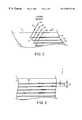
- FIG. 2schematically illustrates a method for forming a servo tracking pattern by irradiating a backcoating layer with a laser beam
- FIG. 3is an enlarged partial view of the backcoating layer having an engraved servo tracking pattern
- FIG. 4 ( a ), FIG. 4 ( b ), FIG. 4 ( c ) and FIG. 4 ( d )schematically illustrate a method for achieving servo control by push-pull method
- FIG. 5shows a discontinuous pattern of servo marks
- FIG. 6 ( a )is a schematic plane view showing a detectable servo track in the form of a series of depressions or pits;
- FIG. 6 ( b )is a schematic cross-sectional view through section a-a 1 showing the structure of the magnetic tape of FIG. 6 ( a ) having a servo track formed of laser engraved marks;
- FIG. 6 ( c )depicts a process for laser engraving an optically detectable servo track onto the non-recording surface of a tape formed as described herein;
- FIG. 7is an enlarged plane view of a single line servo tracking pattern
- FIG. 8is a schematic illustration of light reflected from a rough backcoating surface
- FIG. 9is a schematic illustration of light reflected from a smooth surface
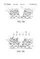
- FIG. 10 ( a )is a schematic view of a dual layer backcoating system of the present invention.
- FIG. 10 ( b )is a schematic illustration of light reflected from the backcoating surface and the servo tracking pattern.
- a magnetic tape 1 shown in FIG. 1comprises a substrate 2 having provided thereon a magnetic layer 4 as a top layer adjoining an optional intermediate layer 3 .
- the magnetic layer 4serves as a recording surface.
- the substrate 2has on its other side a multilayer backcoating system comprising inner layer 5 containing inorganic particles, and outer layer 6 containing inorganic particles which are different from (i.e., larger than) the particles in layer 5 .
- recording surfacemeans a surface used for magnetic recording
- non-recording surfacemeans a surface which does not participate in magnetic recording
- the magnetic tape 1can be for a linear or serpentine recording system, in which the magnetic layer 4 contains a plurality of data tracks in parallel with the tape running direction.
- a head unit having a prescribed number of magnetic headsis moved across the magnetic tape 1 , switching among data tracks, to record or reproduce data on the prescribed data tracks.
- servo trackingis carried out.
- Layer 6is the outermost layer on the non-recording side of the magnetic tape 1 .
- the term “outermost”refers to the layer furthest removed from the substrate 2 .
- Layer 6contains inorganic particles of a size sufficient to provide good mechanical properties, conductivity and heat dissipation to the tape. Mechanical properties include, for example, a tape motion, friction (e.g., between the tape and the tape transport rollers), tape modulation and tape stacking. Inorganic particles of from about 30 nm to about 100 nm in diameter are useful for this purpose. In a currently preferred embodiment, inorganic particles in the size range of from about 50 nm to about 80 nm are used in layer 6 .
- Layer 5is an inner layer on the non-recording surface of magnetic tape 1 .
- Layer 5contains inorganic particles which are smaller than the particles in layer 6 .
- the smaller particlesform a smoother coating (compared to layer 6 ) which allows good servo pattern cutting quality.
- Inorganic particlesof from about 10 nm to about 80 nm in diameter are useful for this purpose. In a currently preferred embodiment, inorganic particles in the range of from about 20 nm to about 35 nm are used in layer 5 .
- the magnetic tape 1may contain additional inner layers, if desired.
- Layers 5 and 6together form what is termed herein the “backcoating system” ( 7 in FIG. 1 ).
- the backcoating system 7may contain additional layers, which may be either clear or pigmented.
- a servo tracking pattern having optical properties which differ from the non-patterned portion of the regioncan be formed on the backcoating system 7 .
- the servo tracking patternpreferably is etched into at least a portion of each of the layers in the backcoating system 7 . While not limiting, the optical properties as referred to herein include properties expressed in terms of the absorbance or reflectance of light.
- FIG. 2illustrates one method by which a servo tracking pattern can be cut, etched or engraved into the backcoating.
- a plurality of laser beams 41emitted in parallel from the respective laser light sources 40 aligned at prescribed intervals across the width direction of the magnetic tape 1 , etch backcoating system 7 running in direction A at a predetermined speed.
- the pattern 10is formed by laser beams 41 .
- the irradiation conditions of the laser beams 41should be controlled so as to produce engraved marks, burn marks or depressions in backcoating system 7 without damaging substrate 2 or layers 3 and 4 on the recording side of the tape.
- the number of lines(shown as four in FIG. 2) may vary.
- the size and depth of the marks in pattern 10are such that when a light or laser beam is shone on the patterned backcoating, the marks can be recognized by measuring the intensity of the light reflected or absorbed by the pattern.
- the pattern 10 shown in the embodiment illustrated in FIG. 3comprises a plurality of continuous lines of prescribed width in parallel to the longitudinal direction of the magnetic tape 1 .
- the width w of each line and variation of the thickness of the pattern 10can be adjusted by controlling the beam diameter and output power of the laser beams 41 .
- the beam diameterpreferably is between about 0.25 to 30 ⁇ m, particularly between about 1 to 25 ⁇ m, and the output power is preferably from about 1 to about 1000 mW, particularly from about 10 to about 100 mW.
- the pattern 10can be formed before use of the magnetic tape 1 or by use of a recording and reproducing drive equipped with an irradiating means.
- the pattern 10is formed over the whole length of backcoating system 7 which corresponds to the length of magnetic layer 4
- the area in which a pattern is to be formedis not limited thereto.
- the pattern 10makes an optical contrast with the non-patterned areas 10 ′ of the backcoating system 7 .
- data tracks of magnetic layer 4can be formed in parallel in the longitudinal direction on the recording side of magnetic tape 1 similarly to pattern 10 , but the relative positional relationship between the data tracks (not shown) and pattern 10 is not limited.
- the optical contrast between pattern 10 and the surrounding non-patterned background 10 ′can be made by irradiating pattern 10 with light of a prescribed wavelength to produce a difference in the intensity of absorbed or reflected light.
- the intensity of the absorbed or reflected lightis detected and processed by an optical servo mechanism, using, for example, a push-pull method or three-beam method, to carry out servo tracking.
- Optical servo mechanismsare commonly employed for achieving optical servo control in various optical disks.
- Servo control based on the contact of reflected light intensity using the push-pull methodcan be carried out as follows.
- a light source 30such as a semiconductor laser, which is placed to face the multilayer backcoating system 7 .
- the light beamthen is condensed through a lens 31 to a prescribed beam diameter, is passed through a half mirror 37 , and impacts on backcoating system 7 and pattern 10 formed in the backcoating system 7 where it is scattered by the rough surface of layer 6 or by depressions 7 ′.
- the beam diameterpreferably should be somewhat smaller than the line width of pattern 10 .
- Some of the lightis reflected by outermost layer 6 and pattern 10 and advances in the direction opposite to the incidence direction.
- the reflected lightis reflected on the half mirror 37 , turning its direction, and enters the light detector 33 , where the intensity of the reflected light is detected.
- the detected reflected lightis converted to electrical signals in the detector 33 and then sent to the servo tracking processor 34 , where the signals are processed by the servo control system.
- the amount and intensity of the light reflected from pattern 10can be distinguished by the detector and/or signal processor from the light reflected from layer 6 .
- the servo tracking processor 34analyzes the intensity of the reflected light. If the beam intensity displays bilateral symmetry, it means that the center of the beam 35 is on the center line of the line width of the pattern 10 as shown in FIG.
- This stateis an “on-track” state, that is, the magnetic head is properly positioned on an aimed data track of the magnetic layer 4 . If the beam intensity lacks bilateral symmetry, it indicates that the beam 35 is deviating from the center line to either left or right as shown in FIG. 4 ( c ) or ( d ).
- This stateis an “off-track” state, that is, the magnetic head is not properly positioned on the aimed data track of the magnetic layer. Then the servo tracking processor 34 gives a drive 35 of the magnetic head 34 instructions to move the magnetic head 36 to a proper position as shown in FIG. 4 ( a ). As a result, the magnetic head 36 is properly positioned by the drive 35 to achieve an “on-track” state.
- the width w (see FIG. 3) of pattern 10preferably is from about 0.25 to about 50 ⁇ m while somewhat varying with the width of the magnetic tape 1 . If the width w is smaller than about 0.25 ⁇ m, optical detection of the pattern 10 may be disturbed because it is difficult to condense the beam to such a small diameter with state-of-the-art techniques. If the width w exceeds about 50 ⁇ m, the density of pattern 10 decreases where the pattern is comprised of a large number of lines as illustrated in FIG. 3. A preferred width w of pattern 10 is from about 0.25 to about 30 ⁇ m, particularly from about 0.8 to about 25 ⁇ m.
- the pitch p of pattern 10i.e., the pitch of the lines or marks (see FIG. 3 ), be not less than the width of the data track formed on the magnetic layer 4 and be an integral multiple of the width of the data track.
- the marks or lines composing pattern 10may be arranged over the whole width of the magnetic tape 1 at prescribed intervals, or a group of marks or lines spaced at prescribed intervals may be localized in, for example, the central portion or either one of side portions of the tape in the width direction. There may be two or more groups of marks or lines localized in two or more positions of the tape in the width direction.
- one or more groups of markswhich may consist of the same or different number of marks, can be arranged on each side portion of the tape; one or more groups of marks, which may consist of the same or different number of marks, can be arranged on the central portion and one of the side portions of the tape; or one or more groups of marks, which may consist of the same or different number of marks, can be arranged on the central portion and each side portion of the tape.
- the total number of the marks (or lines) making up pattern 10preferably is a measure of the number of the data tracks of the magnetic layer.
- the backcoating layertypically serves several essential functions, including: (1) providing satisfactory tape running properties, (2) providing antistatic properties, and (3) detecting the beginning of the tape (BOT) or the end of the tape (EOT).
- the backcoating of the present inventionprovides a medium for carrying servo tracking marks.
- Backcoatingstypically comprise a substantially homogeneous mixture of inorganic particles dispersed in a binder resin.
- the backcoating layers 5 and 6may be formed solely of the inorganic particles but preferably contain a binder in order to improve the running properties and/or durability of magnetic tape 1 .
- the weight percentage of the inorganic particles to the binderwhich is subject to variation according to the size and kind of the particles, is preferably from about 1% to about 90%, still more preferably from about 20% to about 80%.
- thermoplastic resinsthermosetting resins, reactive resins, and mixtures thereof can be used.
- specific examplesinclude vinyl chloride copolymers or modified vinyl chloride copolymers, copolymers comprising acrylic acid, methacrylic acid or esters thereof, polyvinyl alcohol copolymers, acrylonitrile copolymers (rubbery resins), polyester resins, polyurethane resins, epoxy resins, cellulosic resins (e.g. nitrocellulose, cellulose acetate, cellulose acetate butyrate, cellulose acetate propionate, etc.), polyvinyl butyral resins, and polyamide resins.
- vinyl chloride copolymers or modified vinyl chloride copolymerscopolymers comprising acrylic acid, methacrylic acid or esters thereof, polyvinyl alcohol copolymers, acrylonitrile copolymers (rubbery resins), polyester resins, polyurethane resins, epoxy resins, cellulosic resins (e.g. nitro
- binderspreferably have a number average molecular weight of from about 2,000 to about 200,000.
- the binder resincan have a polarizing functional group (so-called polar group), such as a hydroxyl group, a carboxyl group or a salt thereof, a sulfoxyl group or a salt thereof, a phospho group or a salt thereof, a nitro group, a nitric ester group, an acetyl group, a sulfuric ester group or a salt thereof, an epoxy group, a nitrite group, a carbonyl group, an amino group, an alkylamino group, an alkylammonium salt group, a sulfobetaine structure, a carbobetaine structure, and the like, to have improved dispersing properties for particulate additives which could be incorporated into the backcoating (hereinafter described).
- polar groupsuch as a hydroxyl group, a carboxyl group or a salt thereof, a
- the outermost layer 6has a moderate-to-high surface roughness.
- the outermost backcoating layer 6preferably has an arithmetic mean roughness Ra of from about 7 to about 50 nm, more preferably from about 5 to about 30 nm, and most preferably from about 9.0 to about 12.0 mn.
- the outer coating 6also preferably has about a 10 point height parameter Rz of from about 40 to about 250 nm, more preferably from about 50 to about 200 nm, and most preferably from about 80 nm to about 120 nm.
- the inner backcoating layer 5preferably has an arithmetic mean roughness Ra of from about 6 to about 40 nm, more preferably from about 4 to about 20 nm, and most preferably from about 6.0 to about 9.0 nm.
- the inner coatingpreferably has a 10 point Rz of from about 30 to about 200 mn, more preferably from about 40 to about 150 nm, and most preferably from about 50 to about 80 mn.
- the arithmetic mean roughness Radefined by the following equation (1), is measured with a stylus-type profilometer under the following conditions in accordance with JIS-BO601-1994.
- Stylusdiameter 1.5 to 2.5 gm; curvature: 600 Contact pressure: 50 to 300 ⁇ N Cut-off length: 80 ⁇ m Sampling length: 80 ⁇ m Assessment length: 400 ⁇ m
- Ra1 l ⁇ ⁇ l ⁇ ⁇ Y ⁇ ( x ) ⁇ ⁇ ⁇ x ( i )
- Yrepresents profile data
- lrepresents an assessment length
- a sampleis stuck to a slide glass for microscopes which satisfies the requirements specified in JIS-R-3502 (e.g. a slide glass produced by MATSUNAMI GLASS K.K. as used in the present invention) with water or ethanol to prepare a specimen.
- JIS-R-3502e.g. a slide glass produced by MATSUNAMI GLASS K.K. as used in the present invention
- Measurement of the 10 point height parameter Rzcan be made using the same specimen under the same conditions as for the measurement of Ra in accordance with JIS-BO601-1994.
- the sampling length lis 80 ⁇ m, and the assessment length l 0 is 400 ⁇ m.
- Rz⁇ Y p1 + Y p2 + Y p3 + Y p4 ′ + Y p5 ⁇ + Y v1 + Y v2 + Y v3 + Y v4 ′ + Y v5 ( ii )
- Y p1 , Y p2 , Y p3 , Y p4 , and Y p5are heights of the five highest peaks within the assessment length l; and Y v1 , Y v2 , Y v3 , Y v4 , and Y v5 are height of the five lowest valleys within the assessment length l.
- the arithmetic mean roughness Ra and the height parameter Rzare functions of the particle size of the inorganic particles used in the coatings.
- Inorganic powders having an average particle size of from about 1 to about 700 nmcan be used to obtain the desired characteristics.
- the outermost layer 6preferably comprises inorganic particles having a particle size in the range of from about 10 to about 200 nm, more preferably from about 50 nm to about 80 nm.
- the thickness of the outer layer as applied to the magnetic tapepreferably is in the range of from about 0.1 to about 0.5 ⁇ m, more preferably from about 0.1 to about 0.15 ⁇ m.
- the amount of the inorganic particles in the coatingpreferably is from about 5 to about 90% by weight, more preferably from about 42 to about 50% by weight.
- the currently preferred coating as appliedpreferably has the following characteristics:
- Ra9.0 to 12.0 nm
- Rq11.0 to 14.0 nm
- Rz80.0 to 120.0 nm
- the inner layer 5preferably comprises inorganic particles having a particle size in the range of from about 5 to about 100 nm, more preferably from about 20 nm to about 35 nm.
- the thickness of the inner layerpreferably is from about 0.1 to about 0.5 ⁇ m, more preferably from about 0.35 to about 0.40 ⁇ m.
- the amount of inorganic particles in the coatingpreferably is from about 5 to about 80% by weight, more preferably from about 30 to about 40% by weight.
- the resulting coatingpreferably has the following characteristics:
- Ra6.0 to 9.0 nm
- Rq8.0 to 10.0 nm
- Rz50.0 to 80.0 nm
- Inorganic powders which are useful in the present backcoating layersinclude carbon black, metallic powders, metallic oxides, metallic sulfides and mixtures of the aforementioned.
- the powdersare not particularly limited in kind as long as their average particle sizes satisfy the above respective ranges.
- Powders useful in the present inventioninclude, for example, substantially spherical particles of TiO, TiO 2 , ⁇ -Fe 2 O 3 , BaCO 3 , BaSO 4 , Fe 3 O 4 , ⁇ -Al 2 O 3 , y-Al 2 O 3 , CaCO 3 , Cr 2 O 3 , ZnO, ZnSO 4 , ⁇ -FeOOH, Mn-Zn ferrite, Ni-Zn ferrite, ZnS, tin oxide, antimony-doped tin oxide (ATO), indium-doped tin oxide (ITO), indium oxide, carbon black, graphite carbon, SiO 2 , and silicone resins having a three-dimensional network structure made up of siloxane bonds with a methyl group bonded to the silicon atom.
- black powdersuch as carbon black
- Carbon black particlesprovide the additional advantage of being electrically conductive, and thus impart antistatic properties to
- the carbon black contained in the backcoatingmay be any commercially available carbon black having the necessary size and uniformity.
- channel black, furnace black, acetylene black, thermal black, or graphited carbon blackmay be used.
- Carbon black particles in the size ranges required for use in the present inventioncan be obtained from Cabot Corporation (Billerica, Mass.); Asahi Carbon K.K. (Japan); Mitsubishi Kasei Corp. (Japan); Tokai Carbon (Japan): and Akzo N.V. (the Netherlands).
- Non-black inorganic conductive particlesmay be useful in some embodiments of the invention.
- particles of conductive tin oxide, ATO, ITO, and indium oxidemay be advantageous because of their high light transmitting properties in the case where transmitted rather than reflected or absorbed light is utilized for servo signal reading.
- preferred inorganic conductive particlesinclude tin oxide, ATO, ITO, and indium oxide.
- the inorganic conductive particlespreferably are present in an amount of from about 10 to about 800 parts, particularly from about 30 to about 700 parts, especially from about 50 to about 700 parts, by weight per 100 parts by weight of the binder.
- the backcoating layers 5 and 6can contain other additives, such as a lubricant and a hardener.
- a lubricant and a hardenerinclude fatty acids and fatty acid esters.
- fatty acid lubricantsinclude, for example, caproic acid, caprylic acid, capric acid, lauric acid, myristic acid, palmitic acid, stearic acid, isostearic acid, linolenic acid, oleic acid, elaidic acid, behenic acid, malonic acid, succinic acid, maleic acid, glutaric acid, adipic acid, pimelic acid, azelaic acid, sebacic acid, 1,12-dodecanedicarboxylic acid, and octanedicarboxylic acid.
- fatty acid ester lubricantsexamples include alkyl esters of the above-enumerated fatty acids having 16 to 46 carbon atoms in total.
- Inorganic acid esterssuch as phosphoric esters, fluorine-containing compounds, silicone compounds, and the like also are useful as lubricants.
- the lubricantstypically are added in an amount of from about 0.05 to about 15 parts by weight, preferably from about 0.2 to about 10 parts by weight, per about 100 parts by weight of the binder.
- the backcoating layersalso may contain an antioxidant to improve the stability of the coatings.
- the antioxidantpreferably is added in an amount of from about 0.5 to about 20 parts by weight, particularly from about 3 to about 10 parts by weight, per 100 parts by weight of the coloring matter.
- Any antioxidant compatible with backcoating compositionscan be used.
- suitable antioxidantsinclude bis(4-t-butyl-1,2-dithiophenolate) copper-tetra-n-butylammonium and bis(4-t-butyl-1,2-dithiophenolate) nickel-tetra-n-butylammonium.
- the hardenersinclude isocyanate hardeners, exemplified by “CORONATE L” (a trade name, produced by NIPPON POLYURETHANE INDUSTRY Co., Ltd.) and amine hardeners.
- the hardenerscan be added in an amount of from about 5 to about 40 parts by weight, preferably from about 5 to about 30 parts by weight, per 100 parts by weight of the binder.
- the backcoating compositionsfurther may contain stabilizers.
- Backcoating compositions useful for forming the backcoating layerscan be formulated according to art recognized techniques for making these types of coatings.
- the backcoating layersare formed on the tape by coating the substrate 2 with a coating composition having the above-mentioned components dispersed in a solvent.
- suitable solventsinclude ketones, esters, ethers, aromatic hydrocarbons, chlorinated hydrocarbons, and cellosolve solvents.
- the solventpreferably is used in such an amount that the coating composition has a solids content of from about 10 to about 50% by weight, particularly from about 20 to about 40% by weight.
- the present backcoating compositionsmay be formed by any technique appropriate for forming pigmented coatings. Methods of formulating backcoating compositions are well-known, and are described, for example, in co-pending application USSN 09/191,321, and in U.S. Pat. Nos. 5,532,042 and 4,868,046.
- the thickness of the outer layer 6 formed by applying the coating compositionis preferably in the range of from about 0.05 to about 2.0 ⁇ m, more preferably from about 0.1 to about 0.15 ⁇ m.
- the thickness of inner layer 5 , also formed by applying the coating compositionis preferably in the range of from about 0.05 ⁇ m to about 2.0 ⁇ m, more preferably from about 0.35 ⁇ m to about 0.4 ⁇ m.
- the backcoating layersmay consist solely of the inorganic particles.
- Such coatingscan be formed by, for example, one of the following methods (1) to (3):
- CVDchemical vapor deposition
- PVDphysical vapor deposition
- the backcoating layercomprises the inorganic particles and other components
- the other componentsmay include a binder, a lubricant, and the like that could be incorporated into the layers as described above.
- Inorganic powders in addition to the preferred carbon black particlescan be included, for example, to prevent disturbances of the interface between the backcoating layer 5 and the backcoating layer 6 when these two layers are formed by simultaneous coating in a wet-on-wet system, which will be described later in detail.
- the inner backcoating layer 5is formed by coating the substrate with a composition comprising the inorganic particles, a binder and, optionally, one or more of the above-described additional components dispersed in a solvent.
- Outer backcoating layer 6then is formed by applying a coating composition containing inorganic particles and a binder dispersed in a solvent to the substrate coated with inner layers.
- the backcoating compositionscan be applied either by successive coating or simultaneous coating. Noting that the successive coating method may have lower productivity, the preferred coating method is to simultaneously apply both coatings according to a wet-on-wet system, which achieves higher productivity.
- the outer backcoating layer 6 of the magnetic tape 1preferably has a reflectance at 550 to 800 nm of at least about 5%, and preferably in the range of from about 6% to about 10%, before the servo marks are imposed.
- the change in reflectance at the wavelength of incident light used for servo signal reading between the pattern 10 and the non-patterned area of the backcoating surfacei.e. the value represented by equation (2) shown below, be 10% or more, particularly 40% or more.
- Change ⁇ ⁇ in ⁇ ⁇ reflection ⁇ ⁇ ( % )[ Rm - Ro ] Rm ⁇ 100 ( 2 )
- Rorepresents a reflectance (%) of a servo tracking pattern at the wavelength of incident light
- Rinrepresents a reflectance (%) of the area other than the servo tracking pattern at the wavelength of incident light
- the backcoating system 7 of the magnetic tape 1has a pattern 10 of lines along or marks the longitudinal direction of the magnetic tape 1 as shown in FIGS. 3 and 6 ( a ).
- FIG. 3shows four lines, however, a single straight line or a different number of lines along the longitudinal direction of the tape 1 can be used.
- the patternalso may be a single or a plurality of sine curves along the longitudinal direction of the tape 1 .
- pattern 10may comprise discontinuous segments of lines (e.g., discrete marks) along the longitudinal direction of the tape 1 as shown in FIG. 5, or a series of pits or depressions as shown in FIGS. 6 ( a )-( c ).
- the pattern 10 shown in FIG. 5is made up of repeating pairs of pieces 10 a angled at ⁇ °, with the longitudinal direction of magnetic tape 1 and a piece 10 b angled at ⁇ °, the pieces 10 a and 10 b alternating with each other in the longitudinal direction of the tape 1 .
- the angle ⁇has an influence on the precision of positioning by servo tracking.
- a preferred angle ⁇ for securing sufficient precision of positioningis about 5 to about 85°, particularly about 10 to about 30°.
- the lengths of the pieces 10 a and the pieces 10 bmay the same or different, but preferably are the same.
- a preferred length of the pieces 10 a and 10 bis about 5 to 140 mm, particularly about 5 to about 80 mm.
- the spacing g between the piece 10 a and the piece 10 b making each pairis preferably as narrow as possible.
- the servo signals of pattern 10 shown in FIG. 5can be read in the same manner as for the pattern 10 shown in FIG. 3 .
- the pattern 10 representing servo informationpreferably is imposed on the magnetic tape before use.
- the patternis irradiated from the non-recording side of the tape 1 with light having a prescribed wavelength, and the reflected or absorbed light is detected.
- the servo signalsare read as the contrast of reflected light intensity or absorption between the pattern 10 and the non-patterned regions of the backcoating.
- the servo tracking pattern formed in the backcoating system 7can be formed by an engraving process that irradiates the backcoating layers with an energy beam, such as an electron beam, a particle beam, or any laser beam of suitable wavelength, such as for example an ultraviolet laser light beam in the range of about 260-300 nm.
- the depressions so formedextend through the outer layer 6 into backcoating layer 5 , thereby forming optically detectable marks that can be organized into patterns, such as a pattern of dots spaced transversely across the tape.
- the laser engraving processallows formation of marks in the range of from about 1 to about 10 microns. Accordingly, a backcoating layer of a one half inch wide tape can carry many servo tracks.
- laser lightcan be employed for forming a plurality of servo tracks on backcoating layers 6 and 5 , wherein each of the servo tracks comprises a series of linearly spaced sets of dots, each set of dots being arranged transversely across a portion of the backcoating surface.
- the irradiated surface burned or etched by the laser engraving processforms depressions 7 ′ (see FIGS. 6 ( a ) and 6 ( b )) of prescribed depth at regular intervals along the longitudinal direction of the tape.
- the regularly spaced depressionsform the pattern.
- FIG. 6 ( b )shows a cross-sectional view of the depressions 7 ′ in backcoating system 7 .
- the laser beam for pattern formationpreferably has a diameter of from about 0.1 to about 30 ⁇ m, particularly from about 1 to about 10 ⁇ m.
- the output power of the laser beamis selected so as to etch or burn the backcoating layers to form the depressions without damaging the other layers constituting the magnetic tape 1 and the substrate 2 .
- Such an output powerpreferably ranges from about 1 to about 50 mW, particularly about 3 to about 25 mW, per incident beam.
- Short pulses of a high output laser beam of from about 1 to about 100 Wcan also be used.
- the wavelength of the laser beamis preferably about 0.5 to about 1.3 ⁇ m, particularly from about 0.5 to about 0.8 ⁇ m, from the standpoint of the light absorption of the coating.
- the wavelength of the laser beamis preferably from about 0.2 to about 1.3 ⁇ m, particularly from about 0.25 to about 0.8 ⁇ m, from the standpoint of the light absorption of the carbon black.
- FIG. 7depicts an enlarged plane view of a servo tracking pattern.
- the patternis a linear series of depressions or pits located approximately on the centerline of the width direction of the tape 1 .
- the depression 7 ′preferably has a width W of from about 0.1 to about 30 ⁇ m, particularly from about 1 to about 20 ⁇ m for obtaining precise servo control and minimizing the thermal influence on the substrate 2 in pattern formation.
- the length L of each depression 7 ′is preferably from about 1 to about 100 ⁇ m, particularly about 2 to about 20 ⁇ m, to assure servo signal detection.
- the distance P between adjacent depressions 7 ′is preferably from about 2 to about 100 ⁇ m, particularly from about 50 to about 90 ⁇ m, for reading the individual depressions 7 ′ with high sensitivity.
- the distance Pcan be chosen so that the velocity of the tape divided by P is much larger than the bandwidth, or expected bandwidth, of the lateral motion of the tape. This is understood to achieve improved sampling data.
- the depth of each depression 7 ′is preferably at least from about 1 ⁇ 3, more preferably at least 2 ⁇ 3, of the thickness of the inner backcoating layer 5 up to the whole thickness of the inner backcoating layer 5 .
- the tape depicted in FIGS. 6 ( a ) and 6 ( b )may include a reflective layer of a metal or metal alloy having a low melting point, such as aluminum, disposed between backcoating layer 5 and substrate 2 that provides a reflective layer for increasing the reflective characteristic of the servo tracking layer carried on the backcoating.
- the servo tracking patternmay include depressions formed in the metal or metal alloy having a low melting point pattern typically will have a width of from 0.1 ⁇ m to 30 ⁇ m and a depth from one-third the thickness up to the entire thickness of the metal or metal alloy.
- FIG. 2depicts one process for forming a servo layer on the tape.
- a laser engraving processcan be employed that directs a laser beam 41 of selected wavelength toward the surface to be marked, thereby forming a line or a series of pits on the surface that can be detected by an optical servo head, such as described above.
- FIG. 6 ( c )shows an embodiment in which a tape having a plurality of marks 46 formed thereon provide a pattern 45 of three marks that are aligned on an axis that is transverse to an axis perpendicular to the edge of the tape.
- the three mark patterncan be tilted about 7 degrees off axis.
- the laser beam 47(which can be, for example, a UV laser beam in the range of approximately 260 to 330 nm) irradiates the tape to form repeating series of the three dot pattern 45 that can extend along a partial or the full length of the tape.
- the laser beam 47forms pits in the carbon black-containing backcoating layer on the order of about 2 to about 10 microns, with a pitch between marks 46 of about 1 to about 6 microns and a pitch between patterns 45 of about 1 to about 100 microns.
- the mark size and pitchcan be altered according to the specific application.
- the servo trackis “read” by directing a light source, such as a laser beam, onto the backcoating layer 6 .
- the depressions 7 ′reflect light differently than the non-patterned portion of backcoating layer 6 .
- FIG. 8is a schematic illustration showing incident light beams 50 being directed at the rough surface of backcoating 6 . As shown in FIG. 8, reflected light 50 ′ is scattered in several directions by the rough surface of layer 6 . In comparison, FIG. 9 shows that light 50 ′ reflected from smooth layer 5 has less scatter.
- FIG. 10 ( a )is a schematic representation of a backcoating system of the present invention in which pits 7 ′ form part of an optical servo track pattern. In FIG.
- the outer backcoating layer 6contains large carbon particles 6 ′, whereas inner backcoating layer 5 contains smaller carbon particles 5 ′.
- Depressions 7 ′ forming part of an optical servo trackare made through all of layer 6 and at least a portion of layer 5 . As shown in FIG. 10 ( b ), light hitting the depressions is reflected differently than light hitting backcoating 6 .
- This differencecan be detected by an optical detection system such as that depicted in FIG. 4 ( a ).
- light having a wavelength of from about 300 to about 1300 nm, more particularly from about 500 to about 800 nmis preferably used.
- the magnetic layer 4is formed by applying a magnetic coating composition comprising ferromagnetic powder and a binder to a tape substrate.
- the magnetic tape 1is a magnetic tape of coated type.
- magnetic recording coatingsare described in U.S. Pat. No. 4,746,542; U.S. Pat. No. 5,718,964 and U.S. Pat. No. 5,532,042.
- Ferromagnetic powders which can be usedinclude acicular, spindle-shaped or tabular particles.
- Acicular or spindle-shaped ferromagnetic powdersinclude ferromagnetic metal powder consisting mainly of iron and ferromagnetic iron oxide powder, and tabular ferromagnetic powder includes ferromagnetic hexagonal ferrite powder.
- Magnetic recording coatingsare well known and described in the art. Preferred magnetic coatings are described in co-pending co-owned application USSN 09/191,321.
- the tapealso may include an intermediate layer (shown as layer 3 in the FIGS.)
- the intermediate layer 3may be either magnetic or nomnagnetic.
- the magnetic intermediate layer 3is a layer containing magnetic powder, formed by using a magnetic coating composition mainly comprising magnetic powder, nonmagnetic powder, a binder, and a solvent.
- the nonmagnetic intermediate layer 3is a layer formed by using a nonmagnetic coating composition mainly comprising nonmagnetic powder, a binder, and a solvent.
- the coating composition for the intermediate layer 3either magnetic or nonmagnetic, will be inclusively referred to as an intermediate layer coating composition.
- Intermediate layer compositions which can be used in the present inventionare described, for example, on co-pending application 09/191,321.
- the substrate 2can be made of any conventional materials known for magnetic tape, such as those described in Japanese Patent Laid-Open No. 35246/97, column 2, lines 30-42. Of the materials described, nonmagnetic materials such as polyethylene terephthalate (PET), polyethylene naphthalate (PEN), and polyamide are suited.
- PETpolyethylene terephthalate
- PENpolyethylene naphthalate
- the substrate 2preferably has a thickness of about 6 ⁇ m or smaller, particularly about 5 ⁇ m or smaller, for achieving a high recording capacity.
- a layer for easy adhesioncan be provided on the surface of the substrate 2 for improving adhesion to other layer.
- the total thickness of the magnetic tape 1preferably is not greater than about 7 ⁇ m, more preferably from about 4.5 to about 6.8 ⁇ m. That is, the magnetic tape of the aforesaid embodiments is of extremely thin type. In general, stiffness of a magnetic tape decreases with reduction in thickness. It tends to follow that the contact of the magnetic tape with a magnetic head is reduced, which can result in a reduction of output. Where the magnetic tape 1 has a metallic thin layer which has high stiffness, the magnetic tape has high stiffness despite its small thickness. Therefore, the embodiments in which a metallic thin layer is provided are advantageous in that increase in recording capacity by reduction in total thickness can be accomplished without involving the problem of stiffness reduction.
- a preferred method for producing the magnetic tape according to the present inventionis described below.
- a magnetic coating composition for forming the magnetic layer 4 and an intermediate layer coating composition for forming the intermediate layer 3are applied simultaneously to the substrate 2 in a wet-on-wet coating system to form coating layers corresponding to the magnetic layer 4 and the intermediate layer 3 . That is, the magnetic layer 4 is preferably provided while the intermediate layer 3 is wet.
- the coating layersare subjected to magnetic field orientation and dried, and the coated material is wound up. Thereafter, the coated material is calendered, and backcoating compositions are applied onto the back side of the substrate 2 to form the inner backcoating layers 5 and 6 .
- formation of the intermediate layer 3 and the magnetic layer 4may be preceded by formation of the backcoating layers 5 and 6 .
- the coated materialis aged at about 40 to about 80° C. for about 6 to about 100 hours and then slit to a prescribed width to obtain the magnetic tape 1 . Before use of the magnetic tape 1 , a prescribed pattern 10 providing servo signals is formed on the backcoating layers 5 and 6 .
- the magnetic field orientation treatmentis carried out before each coating composition dries.
- the treatmentcan be performed by applying a magnetic field of about 40 kA/m or higher, preferably about 80 to 800 kA/m, in parallel with the side coated with the magnetic coating composition or passing the coated material through a solenoid type magnet of about 80 to 800 kA/m while the magnetic coating composition is wet.
- the ferromagnetic powder in the magnetic layer 4are oriented in the longitudinal direction of the tape 1 .
- the drying of the coating layersis carried out by, for example, supplying gas heated to about 30 to about 120° C.
- the degree of dryingcan be controlled by adjusting the temperature and the feed rate of the gas.
- the calendering of the coated materialis carried out by, for example, supercalendering, comprising passing the coated film between two rolls, such as a combination of a metal roll and a cotton roll or a synthetic resin roll, or a pair of metal rolls.
- the calenderingis preferably carried out, for example, at a temperature of from about 60 to about 140° C. under a linear pressure of from about 1 to about 5 kN/cm.
- the surface of the magnetic layer 4can be subjected to a finishing step, such as burnishing or cleaning. It is possible to apply the magnetic coating composition and the intermediate layer coating composition by a general successive coating technique.
- the magnetic tape 1according to any of the embodiments described herein has a multilayer structure having a magnetic layer 4 and an optional intermediate layer 3 on a substrate 2 , the present invention is also applicable to magnetic tape having no intermediate layer.
- the magnetic tape 1achieves servo control by making use of reflected or absorbed light by selecting the materials constituting the backcoating layers 5 and 6 so as to have a proper reflectance or refractive index, etc.
- the depressions 7 ′ (servo tracking pattern) made in the backcoating layerscan be replaced with a pattern printed on the outer backcoating layer 6 by various printing or coating methods such as gravure coating or ink jet printing.
- servo tracking controlis carried out by utilizing the difference in optical properties between the printed pattern and the other region of the side of the non-recording surface.
- the servo tracking pattern in the foregoing embodimentscan be a combination of (a) one or more than one lines having a prescribed width continuously extending in the longitudinal direction of the magnetic tape 1 and (b) discontinuous lines having a prescribed width arranged along the longitudinal direction of the tape 1 .
- the servo tracking patternmay be composed of dots arranged in a line or a curve or a combination thereof.
- the servo tracking patterncan also be composed of dots (circles, rectangles, triangles, crosses, etc.) or combinations thereof.
- the present magnetic tapecan have a primer layer between the substrate 2 and the intermediate layer 3 or the color-containing layer 5 .
- the magnetic tape according to the present inventionis suitable as audio visual recording tapes such as a DVC tape, an 8-mm video tape, and a DAT tape, and data storage tapes such as a DLT tape, a DDS tape, a 1 ⁇ 4 in data cartridge tape, and a data 8-mm tape.
- audio visual recording tapessuch as a DVC tape, an 8-mm video tape, and a DAT tape
- data storage tapessuch as a DLT tape, a DDS tape, a 1 ⁇ 4 in data cartridge tape, and a data 8-mm tape.
Landscapes
- Engineering & Computer Science (AREA)
- Chemical & Material Sciences (AREA)
- Nanotechnology (AREA)
- Physics & Mathematics (AREA)
- Mathematical Physics (AREA)
- Theoretical Computer Science (AREA)
- Crystallography & Structural Chemistry (AREA)
- Manufacturing & Machinery (AREA)
- Magnetic Record Carriers (AREA)
- Manufacturing Of Magnetic Record Carriers (AREA)
Abstract
Description
| Stylus: | diameter 1.5 to 2.5 gm; curvature: 600 | ||
| Contact pressure: | 50 to 300 μN | ||
| Cut-off length: | 80 μm | ||
| Sampling length: | 80 μm | ||
| Assessment length: | 400 μm | ||


Claims (14)
Priority Applications (3)
| Application Number | Priority Date | Filing Date | Title |
|---|---|---|---|
| US09/376,118US6558774B1 (en) | 1999-08-17 | 1999-08-17 | Multiple-layer backcoating for magnetic tape |
| JP2000246400AJP2001067652A (en) | 1999-08-17 | 2000-08-15 | Manufacture of magnetic tape and recording tape |
| US10/222,420US20030059649A1 (en) | 1999-08-17 | 2002-08-16 | Multiple-layer backcoating for magnetic tape |
Applications Claiming Priority (1)
| Application Number | Priority Date | Filing Date | Title |
|---|---|---|---|
| US09/376,118US6558774B1 (en) | 1999-08-17 | 1999-08-17 | Multiple-layer backcoating for magnetic tape |
Related Child Applications (1)
| Application Number | Title | Priority Date | Filing Date |
|---|---|---|---|
| US10/222,420ContinuationUS20030059649A1 (en) | 1999-08-17 | 2002-08-16 | Multiple-layer backcoating for magnetic tape |
Publications (1)
| Publication Number | Publication Date |
|---|---|
| US6558774B1true US6558774B1 (en) | 2003-05-06 |
Family
ID=23483778
Family Applications (2)
| Application Number | Title | Priority Date | Filing Date |
|---|---|---|---|
| US09/376,118Expired - Fee RelatedUS6558774B1 (en) | 1999-08-17 | 1999-08-17 | Multiple-layer backcoating for magnetic tape |
| US10/222,420AbandonedUS20030059649A1 (en) | 1999-08-17 | 2002-08-16 | Multiple-layer backcoating for magnetic tape |
Family Applications After (1)
| Application Number | Title | Priority Date | Filing Date |
|---|---|---|---|
| US10/222,420AbandonedUS20030059649A1 (en) | 1999-08-17 | 2002-08-16 | Multiple-layer backcoating for magnetic tape |
Country Status (2)
| Country | Link |
|---|---|
| US (2) | US6558774B1 (en) |
| JP (1) | JP2001067652A (en) |
Cited By (19)
| Publication number | Priority date | Publication date | Assignee | Title |
|---|---|---|---|---|
| US20020167751A1 (en)* | 1999-07-27 | 2002-11-14 | Tzuochang Lee | Optical servo track identification on tape storage media |
| US20030035238A1 (en)* | 2001-08-20 | 2003-02-20 | George Bellesis | Optical to magnetic alignment in magnetic tape system |
| US20030161222A1 (en)* | 2002-02-26 | 2003-08-28 | Fuji Photo Film Co., Ltd. | Method of producing master information carrier for magnetic transfer |
| US20030203240A1 (en)* | 2002-04-24 | 2003-10-30 | Daravuth Seng | Dual backout with magnetic servo tracks |
| US6696183B2 (en)* | 2000-09-12 | 2004-02-24 | Sony Corporation | Metallic thin film magnetic recording medium |
| US20050046987A1 (en)* | 2003-08-28 | 2005-03-03 | Quantum Corporation | Correlation receiver for demodulating servo track information |
| US20050057836A1 (en)* | 2003-02-05 | 2005-03-17 | George Saliba | Magnetic media with embedded optical servo tracks |
| US20050057846A1 (en)* | 2003-02-05 | 2005-03-17 | George Saliba | Method and system for tracking magnetic media with embedded optical servo tracks |
| US20050123725A1 (en)* | 2003-12-08 | 2005-06-09 | Imation Corp. | Data storage tape with patterned surface |
| EP1600955A1 (en)* | 2004-05-28 | 2005-11-30 | Fuji Photo Film Co., Ltd. | Information recording tape |
| US7029726B1 (en) | 1999-07-27 | 2006-04-18 | Quantum Corporation | Method for forming a servo pattern on a magnetic tape |
| US7029774B1 (en) | 2005-05-23 | 2006-04-18 | Imation Corp. | Magnetic recording medium with backside to decrease recording surface embossment |
| US7057352B2 (en)* | 2001-04-10 | 2006-06-06 | Samsung Sdi Co., Ltd. | Particle holding sheet, method of manufacturing particle holding sheet and organic electroluminescent display having particle holding sheet |
| US20060199088A1 (en)* | 2005-03-04 | 2006-09-07 | Eastman Kodak Company | Laser etched fiducials in roll-roll display |
| US20060263644A1 (en)* | 2005-05-23 | 2006-11-23 | Greczyna James A | Magnetic recording medium with backside to decrease recording surface embossment |
| US7153366B1 (en)* | 1998-03-24 | 2006-12-26 | Quantum Corporation | Systems and method for forming a servo pattern on a magnetic tape |
| US20080003378A1 (en)* | 2006-06-30 | 2008-01-03 | Imation Corp. | Fluid jet printing recording media layers |
| US7803471B1 (en)* | 2000-12-28 | 2010-09-28 | Hitachi Maxell, Ltd. | Magnetic tape, its cleaning method, and optical servotrack forming/cleaning apparatus |
| US20130255858A1 (en)* | 2012-04-03 | 2013-10-03 | Jun-Chung Hsu | Method of manufacturing a laminate circuit board |
Families Citing this family (98)
| Publication number | Priority date | Publication date | Assignee | Title |
|---|---|---|---|---|
| US6741415B1 (en) | 1999-02-16 | 2004-05-25 | Quantum Corporation | Method of writing servo signal on magnetic tape |
| US6771450B1 (en) | 1999-02-17 | 2004-08-03 | Quantum Corporation | Method of writing servo signal on magnetic tape |
| JP2001148115A (en)* | 1999-11-22 | 2001-05-29 | Hitachi Maxell Ltd | Magnetic recording media |
| US6940676B1 (en) | 2000-06-07 | 2005-09-06 | Quantum Corporation | Triple push-pull optical tracking system |
| US7023650B2 (en) | 2001-11-07 | 2006-04-04 | Quantum Corporation | Optical sensor to recording head alignment |
| ES2395724T3 (en) | 2003-08-20 | 2013-02-14 | Shionogi & Co., Ltd. | New coating composition |
| US20060286768A1 (en)* | 2005-06-16 | 2006-12-21 | Intel Corporation | Method of supporting microelectronic wafer during backside processing |
| JP5569111B2 (en)* | 2009-06-23 | 2014-08-13 | ソニー株式会社 | Magnetic recording medium and method for manufacturing the same |
| US20140123158A1 (en)* | 2011-08-30 | 2014-05-01 | Panasonic Corporation | Mold for tape-shaped optical recording medium, tape-shaped optical recording medium, and cutting device therefor |
| US9493025B2 (en)* | 2015-01-19 | 2016-11-15 | International Business Machines Corporation | Graphene layers for identification of products |
| JP6316248B2 (en) | 2015-08-21 | 2018-04-25 | 富士フイルム株式会社 | Magnetic tape and manufacturing method thereof |
| US10540996B2 (en) | 2015-09-30 | 2020-01-21 | Fujifilm Corporation | Magnetic tape having characterized magnetic layer and magnetic tape device |
| JP6552402B2 (en) | 2015-12-16 | 2019-07-31 | 富士フイルム株式会社 | Magnetic tape, magnetic tape cartridge, magnetic recording / reproducing apparatus, and method of manufacturing magnetic tape |
| US10403319B2 (en) | 2015-12-16 | 2019-09-03 | Fujifilm Corporation | Magnetic tape having characterized magnetic layer, tape cartridge, and recording and reproducing device |
| JP6430927B2 (en) | 2015-12-25 | 2018-11-28 | 富士フイルム株式会社 | Magnetic tape and manufacturing method thereof |
| JP6427127B2 (en) | 2016-02-03 | 2018-11-21 | 富士フイルム株式会社 | Magnetic tape and method of manufacturing the same |
| JP6465823B2 (en) | 2016-02-03 | 2019-02-06 | 富士フイルム株式会社 | Magnetic tape and manufacturing method thereof |
| JP6474748B2 (en) | 2016-02-29 | 2019-02-27 | 富士フイルム株式会社 | Magnetic tape |
| JP6472764B2 (en) | 2016-02-29 | 2019-02-20 | 富士フイルム株式会社 | Magnetic tape |
| JP6467366B2 (en) | 2016-02-29 | 2019-02-13 | 富士フイルム株式会社 | Magnetic tape |
| JP6427132B2 (en)* | 2016-03-23 | 2018-11-21 | 富士フイルム株式会社 | Magnetic tape and magnetic tape device |
| JP6556096B2 (en) | 2016-06-10 | 2019-08-07 | 富士フイルム株式会社 | Magnetic tape and magnetic tape device |
| JP6534637B2 (en) | 2016-06-13 | 2019-06-26 | 富士フイルム株式会社 | Magnetic tape and magnetic tape device |
| JP6556100B2 (en) | 2016-06-22 | 2019-08-07 | 富士フイルム株式会社 | Magnetic tape |
| JP6534969B2 (en) | 2016-06-22 | 2019-06-26 | 富士フイルム株式会社 | Magnetic tape |
| JP6549528B2 (en) | 2016-06-23 | 2019-07-24 | 富士フイルム株式会社 | Magnetic tape and magnetic tape device |
| JP6717684B2 (en) | 2016-06-23 | 2020-07-01 | 富士フイルム株式会社 | Magnetic tape and magnetic tape device |
| JP6556102B2 (en) | 2016-06-23 | 2019-08-07 | 富士フイルム株式会社 | Magnetic tape and magnetic tape device |
| JP6507126B2 (en) | 2016-06-23 | 2019-04-24 | 富士フイルム株式会社 | Magnetic tape and magnetic tape device |
| JP6556101B2 (en) | 2016-06-23 | 2019-08-07 | 富士フイルム株式会社 | Magnetic tape and magnetic tape device |
| JP6496277B2 (en) | 2016-06-23 | 2019-04-03 | 富士フイルム株式会社 | Magnetic tape |
| JP6498154B2 (en) | 2016-06-23 | 2019-04-10 | 富士フイルム株式会社 | Magnetic tape and magnetic tape device |
| JP6549529B2 (en) | 2016-06-23 | 2019-07-24 | 富士フイルム株式会社 | Magnetic tape and magnetic tape device |
| JP6529933B2 (en) | 2016-06-24 | 2019-06-12 | 富士フイルム株式会社 | Magnetic tape |
| JP6556107B2 (en) | 2016-08-31 | 2019-08-07 | 富士フイルム株式会社 | Magnetic tape |
| JP6552467B2 (en) | 2016-08-31 | 2019-07-31 | 富士フイルム株式会社 | Magnetic tape |
| JP6585570B2 (en) | 2016-09-16 | 2019-10-02 | 富士フイルム株式会社 | Magnetic recording medium and method for manufacturing the same |
| JP6701072B2 (en) | 2016-12-27 | 2020-05-27 | 富士フイルム株式会社 | Magnetic tape device and head tracking servo method |
| JP2018106778A (en) | 2016-12-27 | 2018-07-05 | 富士フイルム株式会社 | Magnetic tape device and magnetic reproducing method |
| JP6684203B2 (en) | 2016-12-27 | 2020-04-22 | 富士フイルム株式会社 | Magnetic tape device and magnetic reproducing method |
| JP6588002B2 (en) | 2016-12-27 | 2019-10-09 | 富士フイルム株式会社 | Magnetic tape device and magnetic reproducing method |
| JP6684235B2 (en) | 2017-02-20 | 2020-04-22 | 富士フイルム株式会社 | Magnetic tape device and head tracking servo method |
| JP6684236B2 (en) | 2017-02-20 | 2020-04-22 | 富士フイルム株式会社 | Magnetic tape device and magnetic reproducing method |
| JP6649297B2 (en) | 2017-02-20 | 2020-02-19 | 富士フイルム株式会社 | Magnetic tape device and magnetic reproducing method |
| JP6689223B2 (en) | 2017-02-20 | 2020-04-28 | 富士フイルム株式会社 | Magnetic tape |
| JP6649298B2 (en) | 2017-02-20 | 2020-02-19 | 富士フイルム株式会社 | Magnetic tape device and head tracking servo method |
| JP6684237B2 (en) | 2017-02-20 | 2020-04-22 | 富士フイルム株式会社 | Magnetic tape device and head tracking servo method |
| JP6602806B2 (en) | 2017-02-20 | 2019-11-06 | 富士フイルム株式会社 | Magnetic tape |
| JP6684238B2 (en) | 2017-02-20 | 2020-04-22 | 富士フイルム株式会社 | Magnetic tape |
| JP6684234B2 (en) | 2017-02-20 | 2020-04-22 | 富士フイルム株式会社 | Magnetic tape device and magnetic reproducing method |
| JP6684239B2 (en) | 2017-02-20 | 2020-04-22 | 富士フイルム株式会社 | Magnetic tape |
| JP6685248B2 (en) | 2017-02-20 | 2020-04-22 | 富士フイルム株式会社 | Magnetic tape |
| JP6602805B2 (en) | 2017-02-20 | 2019-11-06 | 富士フイルム株式会社 | Magnetic tape |
| JP6689222B2 (en) | 2017-02-20 | 2020-04-28 | 富士フイルム株式会社 | Magnetic tape |
| JP6637456B2 (en) | 2017-02-20 | 2020-01-29 | 富士フイルム株式会社 | Magnetic tape |
| JP6649313B2 (en) | 2017-03-29 | 2020-02-19 | 富士フイルム株式会社 | Magnetic tape device and magnetic reproducing method |
| JP6626032B2 (en) | 2017-03-29 | 2019-12-25 | 富士フイルム株式会社 | Magnetic tape device and magnetic reproducing method |
| JP6632562B2 (en) | 2017-03-29 | 2020-01-22 | 富士フイルム株式会社 | Magnetic tape |
| JP6649312B2 (en) | 2017-03-29 | 2020-02-19 | 富士フイルム株式会社 | Magnetic tape device and magnetic reproducing method |
| JP6660336B2 (en) | 2017-03-29 | 2020-03-11 | 富士フイルム株式会社 | Magnetic tape device and head tracking servo method |
| JP6649314B2 (en) | 2017-03-29 | 2020-02-19 | 富士フイルム株式会社 | Magnetic tape device and head tracking servo method |
| JP6615814B2 (en) | 2017-03-29 | 2019-12-04 | 富士フイルム株式会社 | Magnetic tape device and head tracking servo method |
| JP6694844B2 (en) | 2017-03-29 | 2020-05-20 | 富士フイルム株式会社 | Magnetic tape device, magnetic reproducing method and head tracking servo method |
| JP6615815B2 (en) | 2017-03-29 | 2019-12-04 | 富士フイルム株式会社 | Magnetic tape device and head tracking servo method |
| JP6626031B2 (en) | 2017-03-29 | 2019-12-25 | 富士フイルム株式会社 | Magnetic tape device and magnetic reproducing method |
| JP6632561B2 (en) | 2017-03-29 | 2020-01-22 | 富士フイルム株式会社 | Magnetic tape device and magnetic reproducing method |
| JP6691512B2 (en) | 2017-06-23 | 2020-04-28 | 富士フイルム株式会社 | Magnetic recording medium |
| JP6723198B2 (en) | 2017-06-23 | 2020-07-15 | 富士フイルム株式会社 | Magnetic tape and magnetic tape device |
| JP6717787B2 (en) | 2017-07-19 | 2020-07-08 | 富士フイルム株式会社 | Magnetic tape and magnetic tape device |
| US10854227B2 (en) | 2017-07-19 | 2020-12-01 | Fujifilm Corporation | Magnetic recording medium having characterized magnetic layer |
| JP6723203B2 (en) | 2017-07-19 | 2020-07-15 | 富士フイルム株式会社 | Magnetic tape |
| JP6723202B2 (en) | 2017-07-19 | 2020-07-15 | 富士フイルム株式会社 | Magnetic tape |
| US10839849B2 (en) | 2017-07-19 | 2020-11-17 | Fujifilm Corporation | Magnetic recording medium having characterized magnetic layer |
| JP6707061B2 (en) | 2017-07-19 | 2020-06-10 | 富士フイルム株式会社 | Magnetic recording medium |
| JP6717786B2 (en) | 2017-07-19 | 2020-07-08 | 富士フイルム株式会社 | Magnetic tape and magnetic tape device |
| JP6707060B2 (en) | 2017-07-19 | 2020-06-10 | 富士フイルム株式会社 | Magnetic tape |
| JP6678135B2 (en) | 2017-07-19 | 2020-04-08 | 富士フイルム株式会社 | Magnetic recording media |
| JP6717785B2 (en) | 2017-07-19 | 2020-07-08 | 富士フイルム株式会社 | Magnetic recording medium |
| JP6714548B2 (en) | 2017-07-19 | 2020-06-24 | 富士フイルム株式会社 | Magnetic tape and magnetic tape device |
| US10854230B2 (en) | 2017-07-19 | 2020-12-01 | Fujifilm Corporation | Magnetic tape having characterized magnetic layer |
| US10978105B2 (en) | 2017-09-29 | 2021-04-13 | Fujifilm Corporation | Magnetic recording medium having characterized magnetic layer and magnetic recording and reproducing device |
| US10515657B2 (en) | 2017-09-29 | 2019-12-24 | Fujifilm Corporation | Magnetic tape having characterized magnetic layer and magnetic recording and reproducing device |
| US10854231B2 (en) | 2017-09-29 | 2020-12-01 | Fujifilm Corporation | Magnetic recording medium having characterized magnetic layer and magnetic recording and reproducing device |
| US10854233B2 (en) | 2017-09-29 | 2020-12-01 | Fujifilm Corporation | Magnetic recording medium having characterized magnetic layer and magnetic recording and reproducing device |
| US10854234B2 (en) | 2017-09-29 | 2020-12-01 | Fujifilm Corporation | Magnetic recording medium having characterized magnetic layer and magnetic recording and reproducing device |
| CN113436653B (en) | 2017-09-29 | 2022-04-26 | 富士胶片株式会社 | Magnetic tape and magnetic recording/reproducing apparatus |
| CN111164686B (en) | 2017-09-29 | 2021-06-08 | 富士胶片株式会社 | Magnetic tape and magnetic recording/reproducing apparatus |
| JP6737415B2 (en)* | 2018-02-16 | 2020-08-12 | ソニー株式会社 | Magnetic recording tape, manufacturing method thereof, and magnetic recording tape cartridge |
| US11514943B2 (en) | 2018-03-23 | 2022-11-29 | Fujifilm Corporation | Magnetic tape and magnetic tape device |
| US11514944B2 (en) | 2018-03-23 | 2022-11-29 | Fujifilm Corporation | Magnetic tape and magnetic tape device |
| US11361792B2 (en) | 2018-03-23 | 2022-06-14 | Fujifilm Corporation | Magnetic tape having characterized magnetic layer and magnetic recording and reproducing device |
| US11361793B2 (en) | 2018-03-23 | 2022-06-14 | Fujifilm Corporation | Magnetic tape having characterized magnetic layer and magnetic recording and reproducing device |
| JP6830931B2 (en) | 2018-07-27 | 2021-02-17 | 富士フイルム株式会社 | Magnetic tapes, magnetic tape cartridges and magnetic tape devices |
| JP6784738B2 (en) | 2018-10-22 | 2020-11-11 | 富士フイルム株式会社 | Magnetic tapes, magnetic tape cartridges and magnetic tape devices |
| JP7042737B2 (en) | 2018-12-28 | 2022-03-28 | 富士フイルム株式会社 | Magnetic tape, magnetic tape cartridge and magnetic tape device |
| JP6830945B2 (en) | 2018-12-28 | 2021-02-17 | 富士フイルム株式会社 | Magnetic tapes, magnetic tape cartridges and magnetic tape devices |
| JP7003073B2 (en) | 2019-01-31 | 2022-01-20 | 富士フイルム株式会社 | Magnetic tapes, magnetic tape cartridges and magnetic tape devices |
| JP6778804B1 (en) | 2019-09-17 | 2020-11-04 | 富士フイルム株式会社 | Magnetic recording medium and magnetic recording / playback device |
Citations (140)
| Publication number | Priority date | Publication date | Assignee | Title |
|---|---|---|---|---|
| US2923781A (en) | 1953-12-10 | 1960-02-02 | Jr Thurlow M Gordon | System for continuously recording sound on film photographically |
| US3404392A (en) | 1962-11-30 | 1968-10-01 | Ibm | Magnetic track following servo system |
| US3426337A (en) | 1964-12-21 | 1969-02-04 | Ibm | Positioning system for random access device |
| US3637991A (en) | 1969-04-14 | 1972-01-25 | Tokyo Shibaura Electric Co | Photoelectric readout apparatus |
| US3662120A (en) | 1968-06-13 | 1972-05-09 | Diffusien De La Culture Europ | Tape recorder useful as an automated teaching apparatus |
| US3768752A (en) | 1971-04-05 | 1973-10-30 | Olivetti & Co Spa | Tape feed and control for character recognition device |
| US3790755A (en) | 1961-12-08 | 1974-02-05 | D Silverman | High density information system using multiple strips |
| US3838291A (en) | 1973-05-17 | 1974-09-24 | Hewlett Packard Co | Detector indicating availability and position of tape |
| DE2406292A1 (en) | 1974-02-09 | 1975-08-14 | Licentia Gmbh | Magnetic tape with optically-read marks on back - corresponding at extremities to smallest and largest number input through keyboard |
| US3914793A (en) | 1974-04-30 | 1975-10-21 | William W Burnham | Tape recorder alignment apparatus |
| US3916039A (en) | 1970-12-15 | 1975-10-28 | Fuji Photo Film Co Ltd | Method of producing magnetic recording tape |
| US3980480A (en) | 1970-09-01 | 1976-09-14 | Urbain Leopold Laridon | Photographic recording and reproduction of information photochromic composition containing polyhalogenated hydrocarbon, spiropyran compound and heterocyclic mercapto compound and the use thereof |
| US4008085A (en) | 1973-12-19 | 1977-02-15 | Agfa-Gevaert N.V. | Photosensitive material containing an organic polyhalogen compound and a dye precursor and the use thereof |
| CH586944A5 (en) | 1975-09-13 | 1977-04-15 | Hardmeyer Raoul | Magnetic data tape carrying additional pulse coded data - has data stored by conductive zones on rear surface tape |
| DE2616362A1 (en) | 1976-04-14 | 1977-11-03 | Philips Patentverwaltung | Magnetic disc servo track production - with servo track produced on disc surface by focussed and modulated laser beam |
| FR2315142B1 (en) | 1975-06-17 | 1977-12-02 | Pyral Soc | |
| US4123788A (en) | 1976-04-10 | 1978-10-31 | U.S. Philips Corporation | Magnetic information carrier with optical servo tracks and apparatus for reading and writing the same |
| US4176381A (en) | 1977-11-11 | 1979-11-27 | U.S. Philips Corporation | Recording and/or reproducing apparatus for a magnetic record carrier in the form of a tape, provided with a control system for the magnetic head position |
| US4275425A (en) | 1978-11-29 | 1981-06-23 | Matsushita Electric Industrial Co., Ltd. | System for automatically transferring information media |
| GB1595136A (en) | 1977-05-10 | 1981-08-05 | Philips Nv | Magnetic tape having optically perceptible markers and method of manufacturing such a tape |
| US4313143A (en) | 1979-09-04 | 1982-01-26 | Minnesota Mining And Manufacturing Co. | Head positioning mechanism for data cartridge recorder |
| US4315283A (en) | 1976-04-08 | 1982-02-09 | Victor Company Of Japan, Ltd. | High density recording system using side-by-side information and servo tracks |
| US4340305A (en) | 1977-05-03 | 1982-07-20 | Massachusetts Institute Of Technology | Plate aligning |
| EP0069548A1 (en) | 1981-07-02 | 1983-01-12 | Irwin International, Inc. | Data record with pre-recorded transducer positioning signals, and system for utilizing same |
| US4371904A (en) | 1980-08-22 | 1983-02-01 | Pertec Computer Corporation | Flexible magnetic disk system |
| US4380032A (en) | 1980-04-25 | 1983-04-12 | Newell Research Corporation | Tape system with optically contrasting data marks |
| GB2121227A (en) | 1982-05-11 | 1983-12-14 | Nigel Geoffrey Ley | Optical memory recording disc |
| US4424111A (en) | 1982-06-01 | 1984-01-03 | Conoco Inc. | Regeneration of ZnC12 |
| SU1137513A1 (en) | 1983-04-25 | 1985-01-30 | Институт Проблем Моделирования В Энергетике Ан Усср | Method of producing optical servo surface of disk-shaped magnetic data medium |
| DE3417426A1 (en) | 1984-05-11 | 1985-11-14 | Silviu 5100 Aachen Carlan | Optical tape length measurement for electronic tape recorders |
| US4558383A (en) | 1983-06-30 | 1985-12-10 | International Business Machines Corporation | Information storage disk transducer position control system using a prerecorded servo pattern requiring no alignment with the storage disk |
| EP0166199A1 (en) | 1984-05-22 | 1986-01-02 | Victor Company Of Japan, Limited | Recording disc and a method for fabricating same |
| EP0097774A3 (en) | 1982-06-30 | 1986-02-05 | International Business Machines Corporation | Transducing system |
| US4570191A (en) | 1984-07-20 | 1986-02-11 | International Business Machines Corporation | Optical sensor for servo position control |
| US4578311A (en) | 1983-05-27 | 1986-03-25 | Fuji Photo Film Co., Ltd. | Magnetic recording medium |
| US4626469A (en) | 1982-06-18 | 1986-12-02 | Fuji Photo Film Co., Ltd. | Magnetic recording material |
| US4633451A (en) | 1982-06-30 | 1986-12-30 | International Business Machines Corporation | Optical servo for magnetic disks |
| US4679104A (en) | 1985-02-08 | 1987-07-07 | Tandberg Data A/S | Method and arrangement for positioning a magnetic head to various tracks of a magnetic tape |
| US4737877A (en) | 1986-05-05 | 1988-04-12 | International Business Machines Corporation | Structure to provide optical and capacitive contrast on magnetic recording disk |
| US4746542A (en) | 1985-11-21 | 1988-05-24 | Fuji Photo Film Co., Ltd. | Coating method for use in the production of magnetic recording medium |
| US4750067A (en) | 1985-07-12 | 1988-06-07 | Minnesota Mining And Manufacturing Company | Head positioning mechanism for data cartridge recorder |
| EP0177737A3 (en) | 1984-08-28 | 1988-07-06 | Fuji Photo Film Co., Ltd. | Optical memory disk and track access therefor |
| US4802030A (en) | 1986-06-25 | 1989-01-31 | Hewlett-Packard Company | Head-tape alignment apparatus with a tape edge find operation |
| EP0119568B1 (en) | 1983-03-19 | 1989-02-08 | GRUNDIG E.M.V. Elektro-Mechanische Versuchsanstalt Max Grundig holländ. Stiftung & Co. KG. | Optoelectronic tape end switching |
| US4816941A (en) | 1987-09-16 | 1989-03-28 | International Business Machines Corporation | Disk file digital servo control system with optimized sampling rate |
| US4816939A (en) | 1986-08-21 | 1989-03-28 | Polaroid Corporation | Magnetic recording media and servo systems using light-transmitting optical gratings |
| EP0311485A1 (en) | 1987-10-05 | 1989-04-12 | Bull S.A. | Servo controlled device for optical reading of and magnetic writing on an information carrier |
| EP0083753B1 (en) | 1982-01-11 | 1989-04-12 | International Business Machines Corporation | Apparatus and method for burnishing magnetic disks |
| EP0108258B1 (en) | 1982-10-08 | 1989-05-10 | Kabushiki Kaisha Toshiba | A master disk for optical disk manufacture, and a method and the system for manufacturing the same |
| DE3201935C2 (en) | 1982-01-22 | 1989-05-24 | Telefunken Fernseh Und Rundfunk Gmbh, 3000 Hannover, De | |
| US4843494A (en) | 1987-10-15 | 1989-06-27 | Polaroid Corporation | Data storage apparatus using optical servo tracks |
| US4848698A (en) | 1988-06-02 | 1989-07-18 | Newell Research Corporation | Method for writing and means for reading position-indicating markers on tape |
| US4868046A (en) | 1986-06-07 | 1989-09-19 | Victor Company Of Japan, Ltd. | Magnetic recording mediums comprising a modified vinyl chloride resin binder in at least a magnetic recording layer |
| US4876886A (en) | 1988-04-04 | 1989-10-31 | Anadrill, Inc. | Method for detecting drilling events from measurement while drilling sensors |
| US4884260A (en) | 1986-04-23 | 1989-11-28 | Drexler Technology Corporation | Data recording system for optical memory tape |
| EP0180258B1 (en) | 1984-10-02 | 1990-02-28 | Océ-Nederland B.V. | Decoder |
| EP0189948B1 (en) | 1985-01-22 | 1990-04-04 | Koninklijke Philips Electronics N.V. | Record-carrier body provided with a relief structure of optically detectable servo-track portions and sector addresses and apparatus for forming said structure |
| EP0353007A3 (en) | 1988-07-27 | 1990-05-23 | Minnesota Mining And Manufacturing Company | Polymethine dyes suitable for optical recording media |
| US4935835A (en) | 1988-11-10 | 1990-06-19 | Insite Peripherals, Inc. | Magnetic media containing reference feature and methods for referencing magnetic head position to the reference feature |
| US4937810A (en) | 1986-04-23 | 1990-06-26 | Drexler Technology Corporation | Optical recording tape with continuous prerecorded tracks |
| US4958245A (en) | 1988-04-07 | 1990-09-18 | Insite Peripherals, Inc. | Apparatus and method for optical servo control with media having information storage and servo control regions of different reflectivities |
| US4961123A (en) | 1988-06-03 | 1990-10-02 | Insite Peripherals | Magnetic information media storage with optical servo tracks |
| US4969058A (en) | 1988-11-10 | 1990-11-06 | Insite Peripherals | CArriage assembly for high track density flexible magnetic disk drive |
| US4983496A (en) | 1988-06-02 | 1991-01-08 | Newell Research Corporation | Method for writing position-indicating markers on magnetic tape |
| EP0351837A3 (en) | 1988-07-21 | 1991-01-09 | Insite Peripherals, Inc. | Read/write head slider with medium access aperture |
| US5008765A (en) | 1989-01-17 | 1991-04-16 | Minnesota Mining And Manufacturing Company | Method and apparatus for reading or writing on tape using a servo positioned multiple channel head |
| US5016240A (en) | 1987-10-07 | 1991-05-14 | The Dow Chemical Company | Optical recording medium |
| EP0244005B1 (en) | 1986-04-21 | 1991-07-24 | Koninklijke Philips Electronics N.V. | Method of scanning a radiation-sensitive recording surface of a rotating disc-shaped carrier by means of a modulated radiation beam and optical write apparatus for carrying out the method |
| US5038030A (en) | 1988-06-03 | 1991-08-06 | Fuji Photo Film Co., Ltd. | Surface identification for back-coated magnetic recording medium |
| EP0155000B1 (en) | 1984-03-16 | 1991-08-14 | Sharp Kabushiki Kaisha | Method of manufacturing optical memory element |
| US5050017A (en) | 1989-08-23 | 1991-09-17 | Eastman Kodak Company | Memory guided magnetic tape tracking |
| US5065387A (en) | 1988-04-07 | 1991-11-12 | Insite Peripherals, Inc. | Method and apparatus for generating tracking error signals by means of an optical servo system |
| US5067039A (en) | 1989-10-20 | 1991-11-19 | Insite Peripherals, Inc. | High track density magnetic media with pitted optical servo tracks and method for stamping the tracks on the media |
| US5105322A (en) | 1990-06-29 | 1992-04-14 | Digital Equipment Corporation | Transverse positioner for read/write head |
| EP0484780A1 (en) | 1990-11-09 | 1992-05-13 | Insite Peripherals, Inc. | Stitched servo pattern and method for positioning an optical-magnetic read/write head |
| US5121371A (en) | 1990-06-18 | 1992-06-09 | Bernoulli Optical Systems Company | Optical servo system for magnetic disk |
| US5120927A (en) | 1988-06-03 | 1992-06-09 | Insite Peripherals, Inc. | High track density media with optical servo tracks and method and apparatus for inscribing the tracks on the media |
| EP0496461A1 (en) | 1991-01-25 | 1992-07-29 | Koninklijke Philips Electronics N.V. | Cassette provided with magnetic tape and method of manufacturing the cassette |
| EP0484779A3 (en) | 1990-11-09 | 1992-09-02 | Insite Peripherals, Inc. | Magnetic media containing a half-checkered reference track for referencing the magnetic head position |
| US5163032A (en) | 1988-06-07 | 1992-11-10 | U.S. Philips Corp. | Magneto-optical recorder with servo control system for a magnetic-field modulation system |
| US5196969A (en) | 1989-03-31 | 1993-03-23 | Sharp Kabushiki Kaisha | Head positioning system for serpentine magnetic recording/reproducing system |
| US5196297A (en) | 1985-12-16 | 1993-03-23 | Polaroid Corporation | Recording material and process of using |
| US5210672A (en) | 1990-11-09 | 1993-05-11 | Insite Peripherals, Inc. | Magnetically indelible media type identification system |
| US5229620A (en) | 1991-12-31 | 1993-07-20 | Tandberg Data A/S | System for integrated tape hole detection by detecting an edge of the tape and/or a pattern on the tape |
| EP0484774A3 (en) | 1990-11-09 | 1993-09-29 | Insite Peripherals, Inc. | Very high-density diskette format method and computer-implemented process |
| US5262908A (en) | 1990-02-20 | 1993-11-16 | Sharp Kabushiki Kaisha | Tracking control device for magnetic recording/reproducing apparatus |
| US5280402A (en) | 1991-08-30 | 1994-01-18 | Minnesota Mining And Manufacturing Company | Combined stepper motor and voice coil head positioning apparatus |
| US5279775A (en) | 1992-06-10 | 1994-01-18 | Iomega Corporation | Acousto-optical intensity control of laser beam during etching of optical servo information of magnetic media |
| US5283773A (en) | 1992-06-10 | 1994-02-01 | Iomega Corporation | Steering laser beam while etching optical servo tracks for magnetic disks |
| US5311378A (en) | 1992-05-05 | 1994-05-10 | Insite Peripherals, Inc. | Dual very-high density magnetic head assembly with optical servo positioning for very high density floppy disk recording and high density format compatability |
| US5319507A (en) | 1991-03-27 | 1994-06-07 | Hitachi Maxell, Ltd. | Recording/reproducing system using a flexible magnetic disk |
| US5322987A (en) | 1992-06-10 | 1994-06-21 | Iomega Corporation | Pneumatic hub locking device for etching optical servo tracks on magnetic disks |
| US5333091A (en) | 1993-01-08 | 1994-07-26 | Arthur D. Little Enterprises, Inc. | Method and apparatus for controlling a videotape player to automatically scan past recorded commercial messages |
| EP0347074B1 (en) | 1988-06-17 | 1994-08-17 | Minnesota Mining And Manufacturing Company | Magnetic tape cartridge identification |
| US5349484A (en) | 1992-12-23 | 1994-09-20 | Eastman Kodak Company | Light pattern detection for film edge following |
| US5369631A (en) | 1991-10-21 | 1994-11-29 | Samsung Electronics Co., Ltd. | Recording/reproducing apparatus for optical tape |
| US5371636A (en) | 1990-03-30 | 1994-12-06 | Archive Corporation | Mechanisms for a closed loop head positioner for streaming tape drives |
| US5379283A (en) | 1993-03-15 | 1995-01-03 | Canon Kabushiki Kaisha | Magneto-optical recording/reproducing method with optical head servo inhibited during magnetic head loading |
| US5379710A (en) | 1993-10-15 | 1995-01-10 | Parnigoni; Johann | Asymmetrical sailing catamaran keels |
| US5414578A (en) | 1993-09-15 | 1995-05-09 | Tandberg Data Storage A/S | Voice coil servo motor for adjusting magnetic head |
| US5414585A (en) | 1993-07-19 | 1995-05-09 | Quantum Corp. | Rotating tape edge guide |
| US5432652A (en) | 1993-06-14 | 1995-07-11 | International Business Machines Corporation | Servo and data format for magnetic tape having plural spaced-apart servo areas interleaved with data track areas having serpentine track scanning using any one of a plurality of number of concurrently accessed tracks |
| US5448430A (en) | 1993-08-05 | 1995-09-05 | International Business Machines Corporation | Track following servo demodulation |
| US5450257A (en) | 1993-03-23 | 1995-09-12 | Minnesota Mining And Manufacturing Company | Head-tape alignment system and method |
| US5452152A (en) | 1990-08-28 | 1995-09-19 | Tandberg Data A/S | Tracking control on longitudinal azimuth tracks using an auxiliary read head |
| US5457586A (en) | 1990-08-14 | 1995-10-10 | Tandberg Data A/S | Method and arrangement for positioning a magnetic head relative to the storage medium of a magnetic layer storage |
| US5462823A (en) | 1992-11-16 | 1995-10-31 | Minnesota Mining And Manufacturing Company | Magnetic recording materials provided with a photosensitive layer |
| EP0564187A3 (en) | 1992-03-26 | 1995-12-06 | Matsushita Electric Industrial Co Ltd | Recording and reproducing apparatus |
| EP0549854B1 (en) | 1991-12-28 | 1996-03-20 | Leybold Aktiengesellschaft | Cathode for coating a substrate |
| US5510140A (en) | 1993-12-01 | 1996-04-23 | Tdk Corporation | Method for preparing magnetic recording medium |
| US5518804A (en) | 1990-12-20 | 1996-05-21 | Fuji Photo Film Co., Ltd. | Magnetic recording medium |
| EP0434230B1 (en) | 1989-11-22 | 1996-05-22 | Sharp Kabushiki Kaisha | Optical recording medium and method of recording and reproducing information thereon |
| US5523904A (en) | 1992-06-24 | 1996-06-04 | Quantum Corporation | Linear tape write servo using embedded azimuth servo blocks |
| US5532042A (en) | 1989-04-05 | 1996-07-02 | Hitachi Maxell, Ltd. | Magnetic recording medium |
| US5563868A (en) | 1990-06-18 | 1996-10-08 | Matsushita-Kotobuki Electronics Industries, Ltd. | Optical servo system for magnetic disk |
| US5566033A (en) | 1992-08-31 | 1996-10-15 | Frame; Gary E. | Method and apparatus for determining the location of information on a magnetic tape |
| US5589247A (en) | 1992-12-22 | 1996-12-31 | Minnesota Mining And Manufacturing Company | Magnetic recording medium having an embossed backcoat layer |
| US5615205A (en) | 1995-06-28 | 1997-03-25 | International Business Machines Corporation | Bi-level optical media having embossed header format |
| US5661616A (en) | 1993-01-12 | 1997-08-26 | Imation Corp. | Track servo control method for data cartridge tape drives |
| US5661823A (en) | 1989-09-29 | 1997-08-26 | Kabushiki Kaisha Toshiba | Image data processing apparatus that automatically sets a data compression rate |
| US5675448A (en) | 1994-12-08 | 1997-10-07 | Imation Corp. | Track pitch error compensation system for data cartridge tape drives |
| EP0606710B1 (en) | 1992-11-16 | 1997-10-08 | Minnesota Mining And Manufacturing Company | Photochemical generation of dyes |
| US5677806A (en) | 1995-06-07 | 1997-10-14 | International Business Machines Corporation | Head locking apparatus in a servo system so that the head can read and write data on a tape without servo trucks |
| US5680278A (en) | 1996-08-08 | 1997-10-21 | Quantum Corporation | Apparatus for combining linear and rotational motion of an azimuth read/write head |
| US5689384A (en) | 1994-06-30 | 1997-11-18 | International Business Machines Corporation | Timing based servo system for magnetic tape systems |
| US5705268A (en) | 1994-12-27 | 1998-01-06 | Kao Corporation | Magnetic recording medium with magnetic powder in lower magnetic layer having protective image diameters |
| US5718964A (en) | 1995-11-02 | 1998-02-17 | Fuji Photo Film Co., Ltd. | Magnetic recording medium |
| US5726834A (en) | 1995-06-07 | 1998-03-10 | International Business Machines Corporation | Actuator for servo actuated tape drive |
| US5774313A (en) | 1994-08-15 | 1998-06-30 | Hitachi Maxell, Ltd. | Magnetic disk which reduces deterioration in regenerated signals due to optical servo grooves |
| EP0645043B1 (en) | 1992-06-10 | 1998-08-12 | Minnesota Mining And Manufacturing Company | Apparatus for and method of verifying etching of optical servo information on magnetic media |
| EP0555511B1 (en) | 1992-02-13 | 1998-11-11 | Tandberg Data Asa | Tape edge tracking apparatus and method compatible with dedicated servo tape formats |
| US5855589A (en) | 1995-08-25 | 1999-01-05 | Mcewen; James A. | Physiologic tourniquet for intravenous regional anesthesia |
| US5858589A (en) | 1995-03-22 | 1999-01-12 | Agfa-Gevaert N.V. | Intensity modulated stochastic screening for preparing a lithographic printing plate |
| US5872675A (en) | 1997-01-21 | 1999-02-16 | Tandberg Data Asa | Tape cartridge with integrated mirror tracking mechanism |
| US5877910A (en) | 1989-10-20 | 1999-03-02 | Insite Peripherals, Inc. | Dual magnetic head and method for writing on very high track density and conventional track density floppy disks |
| JP3094881B2 (en) | 1995-12-20 | 2000-10-03 | マックス株式会社 | Electric stapler |
| JP3141087B2 (en) | 1991-11-21 | 2001-03-05 | ユナイテツド パーセル サービス オブ アメリカ インコーポレイテツド | Equipment for loading and unloading objects |
| JP3201215B2 (en) | 1994-05-25 | 2001-08-20 | 富士ゼロックス株式会社 | Image forming device |
| JP3219432B2 (en) | 1991-09-12 | 2001-10-15 | クローダジャパン株式会社 | External preparation for skin |
| JP3242816B2 (en) | 1995-06-23 | 2001-12-25 | 沖電気工業株式会社 | Information processing device using living tissue |
Family Cites Families (8)
| Publication number | Priority date | Publication date | Assignee | Title |
|---|---|---|---|---|
| JPH01185823A (en)* | 1988-01-20 | 1989-07-25 | Toshiba Corp | Magnetic recording medium |
| JPH01185824A (en)* | 1988-01-20 | 1989-07-25 | Toshiba Corp | magnetic recording medium |
| JPH04170712A (en)* | 1990-11-02 | 1992-06-18 | Hitachi Maxell Ltd | magnetic recording medium |
| JPH06282836A (en)* | 1991-12-26 | 1994-10-07 | Matsushita Electric Ind Co Ltd | Magnetic recording medium |
| JPH06243460A (en)* | 1993-02-15 | 1994-09-02 | Matsushita Electric Ind Co Ltd | Magnetic recording medium |
| JPH1186267A (en)* | 1997-09-03 | 1999-03-30 | Kao Corp | Magnetic recording media |
| JPH11213384A (en)* | 1997-10-22 | 1999-08-06 | Kao Corp | Magnetic tape |
| JP4046397B2 (en)* | 1998-01-27 | 2008-02-13 | クウォンタム・コーポレイション | Magnetic tape |
- 1999
- 1999-08-17USUS09/376,118patent/US6558774B1/ennot_activeExpired - Fee Related
- 2000
- 2000-08-15JPJP2000246400Apatent/JP2001067652A/enactivePending
- 2002
- 2002-08-16USUS10/222,420patent/US20030059649A1/ennot_activeAbandoned
Patent Citations (166)
| Publication number | Priority date | Publication date | Assignee | Title |
|---|---|---|---|---|
| US2923781A (en) | 1953-12-10 | 1960-02-02 | Jr Thurlow M Gordon | System for continuously recording sound on film photographically |
| US3790755A (en) | 1961-12-08 | 1974-02-05 | D Silverman | High density information system using multiple strips |
| US3404392A (en) | 1962-11-30 | 1968-10-01 | Ibm | Magnetic track following servo system |
| US3426337A (en) | 1964-12-21 | 1969-02-04 | Ibm | Positioning system for random access device |
| US3662120A (en) | 1968-06-13 | 1972-05-09 | Diffusien De La Culture Europ | Tape recorder useful as an automated teaching apparatus |
| US3637991A (en) | 1969-04-14 | 1972-01-25 | Tokyo Shibaura Electric Co | Photoelectric readout apparatus |
| US3980480A (en) | 1970-09-01 | 1976-09-14 | Urbain Leopold Laridon | Photographic recording and reproduction of information photochromic composition containing polyhalogenated hydrocarbon, spiropyran compound and heterocyclic mercapto compound and the use thereof |
| US3916039A (en) | 1970-12-15 | 1975-10-28 | Fuji Photo Film Co Ltd | Method of producing magnetic recording tape |
| US3768752A (en) | 1971-04-05 | 1973-10-30 | Olivetti & Co Spa | Tape feed and control for character recognition device |
| US3838291A (en) | 1973-05-17 | 1974-09-24 | Hewlett Packard Co | Detector indicating availability and position of tape |
| US4008085A (en) | 1973-12-19 | 1977-02-15 | Agfa-Gevaert N.V. | Photosensitive material containing an organic polyhalogen compound and a dye precursor and the use thereof |
| DE2406292A1 (en) | 1974-02-09 | 1975-08-14 | Licentia Gmbh | Magnetic tape with optically-read marks on back - corresponding at extremities to smallest and largest number input through keyboard |
| US3914793A (en) | 1974-04-30 | 1975-10-21 | William W Burnham | Tape recorder alignment apparatus |
| FR2315142B1 (en) | 1975-06-17 | 1977-12-02 | Pyral Soc | |
| CH586944A5 (en) | 1975-09-13 | 1977-04-15 | Hardmeyer Raoul | Magnetic data tape carrying additional pulse coded data - has data stored by conductive zones on rear surface tape |
| US4315283A (en) | 1976-04-08 | 1982-02-09 | Victor Company Of Japan, Ltd. | High density recording system using side-by-side information and servo tracks |
| US4123788A (en) | 1976-04-10 | 1978-10-31 | U.S. Philips Corporation | Magnetic information carrier with optical servo tracks and apparatus for reading and writing the same |
| DE2616362A1 (en) | 1976-04-14 | 1977-11-03 | Philips Patentverwaltung | Magnetic disc servo track production - with servo track produced on disc surface by focussed and modulated laser beam |
| US4340305A (en) | 1977-05-03 | 1982-07-20 | Massachusetts Institute Of Technology | Plate aligning |
| GB1595136A (en) | 1977-05-10 | 1981-08-05 | Philips Nv | Magnetic tape having optically perceptible markers and method of manufacturing such a tape |
| US4176381A (en) | 1977-11-11 | 1979-11-27 | U.S. Philips Corporation | Recording and/or reproducing apparatus for a magnetic record carrier in the form of a tape, provided with a control system for the magnetic head position |
| GB2008290B (en) | 1977-11-11 | 1982-03-24 | Philips Nv | Magnetic tape recorder and or reproducer |
| US4275425A (en) | 1978-11-29 | 1981-06-23 | Matsushita Electric Industrial Co., Ltd. | System for automatically transferring information media |
| US4313143A (en) | 1979-09-04 | 1982-01-26 | Minnesota Mining And Manufacturing Co. | Head positioning mechanism for data cartridge recorder |
| US4380032A (en) | 1980-04-25 | 1983-04-12 | Newell Research Corporation | Tape system with optically contrasting data marks |
| US4371904A (en) | 1980-08-22 | 1983-02-01 | Pertec Computer Corporation | Flexible magnetic disk system |
| EP0069548A1 (en) | 1981-07-02 | 1983-01-12 | Irwin International, Inc. | Data record with pre-recorded transducer positioning signals, and system for utilizing same |
| EP0083753B1 (en) | 1982-01-11 | 1989-04-12 | International Business Machines Corporation | Apparatus and method for burnishing magnetic disks |
| DE3201935C2 (en) | 1982-01-22 | 1989-05-24 | Telefunken Fernseh Und Rundfunk Gmbh, 3000 Hannover, De | |
| GB2121227A (en) | 1982-05-11 | 1983-12-14 | Nigel Geoffrey Ley | Optical memory recording disc |
| US4424111A (en) | 1982-06-01 | 1984-01-03 | Conoco Inc. | Regeneration of ZnC12 |
| US4626469A (en) | 1982-06-18 | 1986-12-02 | Fuji Photo Film Co., Ltd. | Magnetic recording material |
| US4633451A (en) | 1982-06-30 | 1986-12-30 | International Business Machines Corporation | Optical servo for magnetic disks |
| EP0097774A3 (en) | 1982-06-30 | 1986-02-05 | International Business Machines Corporation | Transducing system |
| EP0108258B1 (en) | 1982-10-08 | 1989-05-10 | Kabushiki Kaisha Toshiba | A master disk for optical disk manufacture, and a method and the system for manufacturing the same |
| EP0119568B1 (en) | 1983-03-19 | 1989-02-08 | GRUNDIG E.M.V. Elektro-Mechanische Versuchsanstalt Max Grundig holländ. Stiftung & Co. KG. | Optoelectronic tape end switching |
| SU1137513A1 (en) | 1983-04-25 | 1985-01-30 | Институт Проблем Моделирования В Энергетике Ан Усср | Method of producing optical servo surface of disk-shaped magnetic data medium |
| US4578311A (en) | 1983-05-27 | 1986-03-25 | Fuji Photo Film Co., Ltd. | Magnetic recording medium |
| EP0130495B1 (en) | 1983-06-30 | 1988-03-30 | International Business Machines Corporation | A record disk bearing a servo pattern and record disk apparatus comprising such a record disk |
| US4558383A (en) | 1983-06-30 | 1985-12-10 | International Business Machines Corporation | Information storage disk transducer position control system using a prerecorded servo pattern requiring no alignment with the storage disk |
| EP0155000B1 (en) | 1984-03-16 | 1991-08-14 | Sharp Kabushiki Kaisha | Method of manufacturing optical memory element |
| DE3417426A1 (en) | 1984-05-11 | 1985-11-14 | Silviu 5100 Aachen Carlan | Optical tape length measurement for electronic tape recorders |
| EP0166199A1 (en) | 1984-05-22 | 1986-01-02 | Victor Company Of Japan, Limited | Recording disc and a method for fabricating same |
| US4570191A (en) | 1984-07-20 | 1986-02-11 | International Business Machines Corporation | Optical sensor for servo position control |
| EP0177737A3 (en) | 1984-08-28 | 1988-07-06 | Fuji Photo Film Co., Ltd. | Optical memory disk and track access therefor |
| EP0180258B1 (en) | 1984-10-02 | 1990-02-28 | Océ-Nederland B.V. | Decoder |
| EP0189948B1 (en) | 1985-01-22 | 1990-04-04 | Koninklijke Philips Electronics N.V. | Record-carrier body provided with a relief structure of optically detectable servo-track portions and sector addresses and apparatus for forming said structure |
| US4679104A (en) | 1985-02-08 | 1987-07-07 | Tandberg Data A/S | Method and arrangement for positioning a magnetic head to various tracks of a magnetic tape |
| US4750067A (en) | 1985-07-12 | 1988-06-07 | Minnesota Mining And Manufacturing Company | Head positioning mechanism for data cartridge recorder |
| US4746542A (en) | 1985-11-21 | 1988-05-24 | Fuji Photo Film Co., Ltd. | Coating method for use in the production of magnetic recording medium |
| US5196297A (en) | 1985-12-16 | 1993-03-23 | Polaroid Corporation | Recording material and process of using |
| EP0244005B1 (en) | 1986-04-21 | 1991-07-24 | Koninklijke Philips Electronics N.V. | Method of scanning a radiation-sensitive recording surface of a rotating disc-shaped carrier by means of a modulated radiation beam and optical write apparatus for carrying out the method |
| US4884260A (en) | 1986-04-23 | 1989-11-28 | Drexler Technology Corporation | Data recording system for optical memory tape |
| US4937810A (en) | 1986-04-23 | 1990-06-26 | Drexler Technology Corporation | Optical recording tape with continuous prerecorded tracks |
| US4737877A (en) | 1986-05-05 | 1988-04-12 | International Business Machines Corporation | Structure to provide optical and capacitive contrast on magnetic recording disk |
| US4868046A (en) | 1986-06-07 | 1989-09-19 | Victor Company Of Japan, Ltd. | Magnetic recording mediums comprising a modified vinyl chloride resin binder in at least a magnetic recording layer |
| US4802030A (en) | 1986-06-25 | 1989-01-31 | Hewlett-Packard Company | Head-tape alignment apparatus with a tape edge find operation |
| US4816939A (en) | 1986-08-21 | 1989-03-28 | Polaroid Corporation | Magnetic recording media and servo systems using light-transmitting optical gratings |
| EP0257713B1 (en) | 1986-08-21 | 1994-04-20 | Polaroid Corporation | System and method for reading and/or writing data on a magnetic recording medium |
| US4816941A (en) | 1987-09-16 | 1989-03-28 | International Business Machines Corporation | Disk file digital servo control system with optimized sampling rate |
| EP0311485A1 (en) | 1987-10-05 | 1989-04-12 | Bull S.A. | Servo controlled device for optical reading of and magnetic writing on an information carrier |
| US5016240A (en) | 1987-10-07 | 1991-05-14 | The Dow Chemical Company | Optical recording medium |
| US4843494A (en) | 1987-10-15 | 1989-06-27 | Polaroid Corporation | Data storage apparatus using optical servo tracks |
| EP0311859B1 (en) | 1987-10-15 | 1994-04-20 | Polaroid Corporation | Data storage apparatus |
| US4876886A (en) | 1988-04-04 | 1989-10-31 | Anadrill, Inc. | Method for detecting drilling events from measurement while drilling sensors |
| EP0336419B1 (en) | 1988-04-07 | 1994-09-07 | Insite Peripherals, Inc. | Apparatus and method for optical servo control with media having information storage and servo control regions of different reflectivities |
| US4958245A (en) | 1988-04-07 | 1990-09-18 | Insite Peripherals, Inc. | Apparatus and method for optical servo control with media having information storage and servo control regions of different reflectivities |
| US5065387A (en) | 1988-04-07 | 1991-11-12 | Insite Peripherals, Inc. | Method and apparatus for generating tracking error signals by means of an optical servo system |
| US4848698A (en) | 1988-06-02 | 1989-07-18 | Newell Research Corporation | Method for writing and means for reading position-indicating markers on tape |
| US4983496A (en) | 1988-06-02 | 1991-01-08 | Newell Research Corporation | Method for writing position-indicating markers on magnetic tape |
| US5038030A (en) | 1988-06-03 | 1991-08-06 | Fuji Photo Film Co., Ltd. | Surface identification for back-coated magnetic recording medium |
| US4961123A (en) | 1988-06-03 | 1990-10-02 | Insite Peripherals | Magnetic information media storage with optical servo tracks |
| EP0344759B1 (en) | 1988-06-03 | 1994-09-28 | Insite Peripherals, Inc. | High track density media with optical servo tracks and method and apparatus for inscribing the tracks on the media |
| US5120927A (en) | 1988-06-03 | 1992-06-09 | Insite Peripherals, Inc. | High track density media with optical servo tracks and method and apparatus for inscribing the tracks on the media |
| US5163032A (en) | 1988-06-07 | 1992-11-10 | U.S. Philips Corp. | Magneto-optical recorder with servo control system for a magnetic-field modulation system |
| EP0347074B1 (en) | 1988-06-17 | 1994-08-17 | Minnesota Mining And Manufacturing Company | Magnetic tape cartridge identification |
| EP0351837A3 (en) | 1988-07-21 | 1991-01-09 | Insite Peripherals, Inc. | Read/write head slider with medium access aperture |
| EP0353007A3 (en) | 1988-07-27 | 1990-05-23 | Minnesota Mining And Manufacturing Company | Polymethine dyes suitable for optical recording media |
| EP0368269B1 (en) | 1988-11-10 | 1995-01-25 | Insite Peripherals, Inc. | Magnetic media containing reference feature and methods for referencing magnetic head position to the reference feature |
| US4969058A (en) | 1988-11-10 | 1990-11-06 | Insite Peripherals | CArriage assembly for high track density flexible magnetic disk drive |
| US4935835A (en) | 1988-11-10 | 1990-06-19 | Insite Peripherals, Inc. | Magnetic media containing reference feature and methods for referencing magnetic head position to the reference feature |
| EP0368268B1 (en) | 1988-11-10 | 1995-01-25 | Insite Peripherals, Inc. | Carriage assembly for high track density flexible magnetic disk drive |
| US5008765A (en) | 1989-01-17 | 1991-04-16 | Minnesota Mining And Manufacturing Company | Method and apparatus for reading or writing on tape using a servo positioned multiple channel head |
| EP0390555B1 (en) | 1989-03-31 | 1995-05-10 | Sharp Kabushiki Kaisha | Magnetic recording/reproducing apparatus |
| US5196969A (en) | 1989-03-31 | 1993-03-23 | Sharp Kabushiki Kaisha | Head positioning system for serpentine magnetic recording/reproducing system |
| US5532042A (en) | 1989-04-05 | 1996-07-02 | Hitachi Maxell, Ltd. | Magnetic recording medium |
| US5050017A (en) | 1989-08-23 | 1991-09-17 | Eastman Kodak Company | Memory guided magnetic tape tracking |
| US5661823A (en) | 1989-09-29 | 1997-08-26 | Kabushiki Kaisha Toshiba | Image data processing apparatus that automatically sets a data compression rate |
| US5067039A (en) | 1989-10-20 | 1991-11-19 | Insite Peripherals, Inc. | High track density magnetic media with pitted optical servo tracks and method for stamping the tracks on the media |
| US5877910A (en) | 1989-10-20 | 1999-03-02 | Insite Peripherals, Inc. | Dual magnetic head and method for writing on very high track density and conventional track density floppy disks |
| EP0423662B1 (en) | 1989-10-20 | 1996-01-03 | Insite Peripherals, Inc. | High track density magnetic media with pitted optical servo tracks and method for stamping the tracks on the media |
| US5674583A (en) | 1989-11-22 | 1997-10-07 | Sharp Kabushiki Kaisha | Optical recording medium and manufacturing method thereof |
| EP0434230B1 (en) | 1989-11-22 | 1996-05-22 | Sharp Kabushiki Kaisha | Optical recording medium and method of recording and reproducing information thereon |
| US5262908A (en) | 1990-02-20 | 1993-11-16 | Sharp Kabushiki Kaisha | Tracking control device for magnetic recording/reproducing apparatus |
| EP0443810B1 (en) | 1990-02-20 | 1995-06-28 | Sharp Kabushiki Kaisha | Tracking control device for magnetic recording/reproducing apparatus |
| US5371636A (en) | 1990-03-30 | 1994-12-06 | Archive Corporation | Mechanisms for a closed loop head positioner for streaming tape drives |
| EP0535112B1 (en) | 1990-06-18 | 1996-12-11 | Matsushita Kotobuki Electronics Industry Ltd. | Optical servo system for magnetic disk |
| US5563868A (en) | 1990-06-18 | 1996-10-08 | Matsushita-Kotobuki Electronics Industries, Ltd. | Optical servo system for magnetic disk |
| US5121371A (en) | 1990-06-18 | 1992-06-09 | Bernoulli Optical Systems Company | Optical servo system for magnetic disk |
| US5105322A (en) | 1990-06-29 | 1992-04-14 | Digital Equipment Corporation | Transverse positioner for read/write head |
| US5457586A (en) | 1990-08-14 | 1995-10-10 | Tandberg Data A/S | Method and arrangement for positioning a magnetic head relative to the storage medium of a magnetic layer storage |
| US5452152A (en) | 1990-08-28 | 1995-09-19 | Tandberg Data A/S | Tracking control on longitudinal azimuth tracks using an auxiliary read head |
| EP0484774A3 (en) | 1990-11-09 | 1993-09-29 | Insite Peripherals, Inc. | Very high-density diskette format method and computer-implemented process |
| US5210672A (en) | 1990-11-09 | 1993-05-11 | Insite Peripherals, Inc. | Magnetically indelible media type identification system |
| US5363255A (en) | 1990-11-09 | 1994-11-08 | Insite Peripherals, Inc. | Disk drive for communicating with removable media that include media type identification information |
| EP0484780A1 (en) | 1990-11-09 | 1992-05-13 | Insite Peripherals, Inc. | Stitched servo pattern and method for positioning an optical-magnetic read/write head |
| EP0484775A3 (en) | 1990-11-09 | 1995-03-08 | Insite Peripherals | |
| EP0484779A3 (en) | 1990-11-09 | 1992-09-02 | Insite Peripherals, Inc. | Magnetic media containing a half-checkered reference track for referencing the magnetic head position |
| US5535069A (en) | 1990-11-09 | 1996-07-09 | Insite Peripherals, Inc. | Very high-density diskette format method and computer-implemented process |
| US5515212A (en) | 1990-11-09 | 1996-05-07 | Insite Peripherals, Inc. | Very high-density diskette format method and computer implemented process |
| DE4142052C2 (en) | 1990-12-20 | 1999-07-15 | Fuji Photo Film Co Ltd | Magnetic recording medium |
| US5518804A (en) | 1990-12-20 | 1996-05-21 | Fuji Photo Film Co., Ltd. | Magnetic recording medium |
| EP0496461A1 (en) | 1991-01-25 | 1992-07-29 | Koninklijke Philips Electronics N.V. | Cassette provided with magnetic tape and method of manufacturing the cassette |
| US5319507A (en) | 1991-03-27 | 1994-06-07 | Hitachi Maxell, Ltd. | Recording/reproducing system using a flexible magnetic disk |
| US5280402A (en) | 1991-08-30 | 1994-01-18 | Minnesota Mining And Manufacturing Company | Combined stepper motor and voice coil head positioning apparatus |
| JP3219432B2 (en) | 1991-09-12 | 2001-10-15 | クローダジャパン株式会社 | External preparation for skin |
| US5369631A (en) | 1991-10-21 | 1994-11-29 | Samsung Electronics Co., Ltd. | Recording/reproducing apparatus for optical tape |
| JP3141087B2 (en) | 1991-11-21 | 2001-03-05 | ユナイテツド パーセル サービス オブ アメリカ インコーポレイテツド | Equipment for loading and unloading objects |
| EP0549854B1 (en) | 1991-12-28 | 1996-03-20 | Leybold Aktiengesellschaft | Cathode for coating a substrate |
| US5229620A (en) | 1991-12-31 | 1993-07-20 | Tandberg Data A/S | System for integrated tape hole detection by detecting an edge of the tape and/or a pattern on the tape |
| EP0549845B1 (en) | 1991-12-31 | 1998-07-08 | Tandberg Data Asa | System for integrated tape hole detection |
| EP0555511B1 (en) | 1992-02-13 | 1998-11-11 | Tandberg Data Asa | Tape edge tracking apparatus and method compatible with dedicated servo tape formats |
| EP0564187A3 (en) | 1992-03-26 | 1995-12-06 | Matsushita Electric Industrial Co Ltd | Recording and reproducing apparatus |
| US5311378A (en) | 1992-05-05 | 1994-05-10 | Insite Peripherals, Inc. | Dual very-high density magnetic head assembly with optical servo positioning for very high density floppy disk recording and high density format compatability |
| US5279775A (en) | 1992-06-10 | 1994-01-18 | Iomega Corporation | Acousto-optical intensity control of laser beam during etching of optical servo information of magnetic media |
| EP0645043B1 (en) | 1992-06-10 | 1998-08-12 | Minnesota Mining And Manufacturing Company | Apparatus for and method of verifying etching of optical servo information on magnetic media |
| US5283773A (en) | 1992-06-10 | 1994-02-01 | Iomega Corporation | Steering laser beam while etching optical servo tracks for magnetic disks |
| EP0655960B1 (en) | 1992-06-10 | 1998-08-12 | Minnesota Mining And Manufacturing Company | Pneumatic hub locking device for etching optical servo tracks on magnetic disks |
| EP0645044B1 (en) | 1992-06-10 | 1998-08-12 | Minnesota Mining And Manufacturing Company | Steering laser beam while etching optical servo tracks for magnetic disks |
| US5322987A (en) | 1992-06-10 | 1994-06-21 | Iomega Corporation | Pneumatic hub locking device for etching optical servo tracks on magnetic disks |
| US5523904A (en) | 1992-06-24 | 1996-06-04 | Quantum Corporation | Linear tape write servo using embedded azimuth servo blocks |
| US5566033A (en) | 1992-08-31 | 1996-10-15 | Frame; Gary E. | Method and apparatus for determining the location of information on a magnetic tape |
| EP0598503B1 (en) | 1992-11-16 | 1998-12-09 | Minnesota Mining And Manufacturing Company | Magnetic recording materials |
| US5462823A (en) | 1992-11-16 | 1995-10-31 | Minnesota Mining And Manufacturing Company | Magnetic recording materials provided with a photosensitive layer |
| EP0606710B1 (en) | 1992-11-16 | 1997-10-08 | Minnesota Mining And Manufacturing Company | Photochemical generation of dyes |
| US5589247A (en) | 1992-12-22 | 1996-12-31 | Minnesota Mining And Manufacturing Company | Magnetic recording medium having an embossed backcoat layer |
| US5349484A (en) | 1992-12-23 | 1994-09-20 | Eastman Kodak Company | Light pattern detection for film edge following |
| US5333091B2 (en) | 1993-01-08 | 1996-12-17 | Arthur D Little Enterprises | Method and apparatus for controlling a videotape player to automatically scan past recorded commercial messages |
| US5333091A (en) | 1993-01-08 | 1994-07-26 | Arthur D. Little Enterprises, Inc. | Method and apparatus for controlling a videotape player to automatically scan past recorded commercial messages |
| US5333091B1 (en) | 1993-01-08 | 1996-05-07 | Arthur D Little Enterprises | Method and apparatus for controlling a videotape player to automatically scan past recorded commercial messages |
| US5661616A (en) | 1993-01-12 | 1997-08-26 | Imation Corp. | Track servo control method for data cartridge tape drives |
| US5379283A (en) | 1993-03-15 | 1995-01-03 | Canon Kabushiki Kaisha | Magneto-optical recording/reproducing method with optical head servo inhibited during magnetic head loading |
| US5450257A (en) | 1993-03-23 | 1995-09-12 | Minnesota Mining And Manufacturing Company | Head-tape alignment system and method |
| US5432652A (en) | 1993-06-14 | 1995-07-11 | International Business Machines Corporation | Servo and data format for magnetic tape having plural spaced-apart servo areas interleaved with data track areas having serpentine track scanning using any one of a plurality of number of concurrently accessed tracks |
| US5414585A (en) | 1993-07-19 | 1995-05-09 | Quantum Corp. | Rotating tape edge guide |
| US5448430A (en) | 1993-08-05 | 1995-09-05 | International Business Machines Corporation | Track following servo demodulation |
| US5414578A (en) | 1993-09-15 | 1995-05-09 | Tandberg Data Storage A/S | Voice coil servo motor for adjusting magnetic head |
| US5379710A (en) | 1993-10-15 | 1995-01-10 | Parnigoni; Johann | Asymmetrical sailing catamaran keels |
| US5510140A (en) | 1993-12-01 | 1996-04-23 | Tdk Corporation | Method for preparing magnetic recording medium |
| EP0684597A4 (en) | 1993-12-01 | 1996-05-22 | Tdk Corp | Production method of magnetic recording medium. |
| JP3201215B2 (en) | 1994-05-25 | 2001-08-20 | 富士ゼロックス株式会社 | Image forming device |
| US5689384A (en) | 1994-06-30 | 1997-11-18 | International Business Machines Corporation | Timing based servo system for magnetic tape systems |
| US5774313A (en) | 1994-08-15 | 1998-06-30 | Hitachi Maxell, Ltd. | Magnetic disk which reduces deterioration in regenerated signals due to optical servo grooves |
| US5675448A (en) | 1994-12-08 | 1997-10-07 | Imation Corp. | Track pitch error compensation system for data cartridge tape drives |
| US5705268A (en) | 1994-12-27 | 1998-01-06 | Kao Corporation | Magnetic recording medium with magnetic powder in lower magnetic layer having protective image diameters |
| US5858589A (en) | 1995-03-22 | 1999-01-12 | Agfa-Gevaert N.V. | Intensity modulated stochastic screening for preparing a lithographic printing plate |
| US5726834A (en) | 1995-06-07 | 1998-03-10 | International Business Machines Corporation | Actuator for servo actuated tape drive |
| US5677806A (en) | 1995-06-07 | 1997-10-14 | International Business Machines Corporation | Head locking apparatus in a servo system so that the head can read and write data on a tape without servo trucks |
| JP3242816B2 (en) | 1995-06-23 | 2001-12-25 | 沖電気工業株式会社 | Information processing device using living tissue |
| US5615205A (en) | 1995-06-28 | 1997-03-25 | International Business Machines Corporation | Bi-level optical media having embossed header format |
| US5855589A (en) | 1995-08-25 | 1999-01-05 | Mcewen; James A. | Physiologic tourniquet for intravenous regional anesthesia |
| US5718964A (en) | 1995-11-02 | 1998-02-17 | Fuji Photo Film Co., Ltd. | Magnetic recording medium |
| JP3094881B2 (en) | 1995-12-20 | 2000-10-03 | マックス株式会社 | Electric stapler |
| US5680278A (en) | 1996-08-08 | 1997-10-21 | Quantum Corporation | Apparatus for combining linear and rotational motion of an azimuth read/write head |
| EP0854471B1 (en) | 1997-01-21 | 2000-03-08 | Tandberg Data ASA | Tape cartridge with integrated mirror tracking mechanism |
| US5872675A (en) | 1997-01-21 | 1999-02-16 | Tandberg Data Asa | Tape cartridge with integrated mirror tracking mechanism |
Non-Patent Citations (1)
| Title |
|---|
| English Translation of JP 04-252417 A.* |
Cited By (28)
| Publication number | Priority date | Publication date | Assignee | Title |
|---|---|---|---|---|
| US7153366B1 (en)* | 1998-03-24 | 2006-12-26 | Quantum Corporation | Systems and method for forming a servo pattern on a magnetic tape |
| US7029726B1 (en) | 1999-07-27 | 2006-04-18 | Quantum Corporation | Method for forming a servo pattern on a magnetic tape |
| US6961200B2 (en)* | 1999-07-27 | 2005-11-01 | Quantum Corporation | Optical servo track identification on tape storage media |
| US20020167751A1 (en)* | 1999-07-27 | 2002-11-14 | Tzuochang Lee | Optical servo track identification on tape storage media |
| US6696183B2 (en)* | 2000-09-12 | 2004-02-24 | Sony Corporation | Metallic thin film magnetic recording medium |
| US20150056474A1 (en)* | 2000-12-28 | 2015-02-26 | Hitachi Maxell, Ltd. | Magnetic tape, its cleaning method, and optical servotrack forming/cleaning apparatus |
| US20100319728A1 (en)* | 2000-12-28 | 2010-12-23 | Hiroyuki Ota | Magnetic tape, method of cleaning the same, and apparatus for forming and cleaning optical servo tracks |
| US7803471B1 (en)* | 2000-12-28 | 2010-09-28 | Hitachi Maxell, Ltd. | Magnetic tape, its cleaning method, and optical servotrack forming/cleaning apparatus |
| US7057352B2 (en)* | 2001-04-10 | 2006-06-06 | Samsung Sdi Co., Ltd. | Particle holding sheet, method of manufacturing particle holding sheet and organic electroluminescent display having particle holding sheet |
| US6940681B2 (en)* | 2001-08-20 | 2005-09-06 | Quantum Corporation | Optical to magnetic alignment in magnetic tape system |
| US20030035238A1 (en)* | 2001-08-20 | 2003-02-20 | George Bellesis | Optical to magnetic alignment in magnetic tape system |
| US20030161222A1 (en)* | 2002-02-26 | 2003-08-28 | Fuji Photo Film Co., Ltd. | Method of producing master information carrier for magnetic transfer |
| US20030203240A1 (en)* | 2002-04-24 | 2003-10-30 | Daravuth Seng | Dual backout with magnetic servo tracks |
| US20050057846A1 (en)* | 2003-02-05 | 2005-03-17 | George Saliba | Method and system for tracking magnetic media with embedded optical servo tracks |
| US6980390B2 (en)* | 2003-02-05 | 2005-12-27 | Quantum Corporation | Magnetic media with embedded optical servo tracks |
| US20050057836A1 (en)* | 2003-02-05 | 2005-03-17 | George Saliba | Magnetic media with embedded optical servo tracks |
| US7187515B2 (en)* | 2003-02-05 | 2007-03-06 | Quantum Corporation | Method and system for tracking magnetic media with embedded optical servo tracks |
| US20050046987A1 (en)* | 2003-08-28 | 2005-03-03 | Quantum Corporation | Correlation receiver for demodulating servo track information |
| US7230782B2 (en)* | 2003-08-28 | 2007-06-12 | Quantum Corporation | Correlation receiver for demodulating servo track information |
| US20050123725A1 (en)* | 2003-12-08 | 2005-06-09 | Imation Corp. | Data storage tape with patterned surface |
| US7018730B2 (en)* | 2003-12-08 | 2006-03-28 | Imation Corp. | Data storage tape with patterned surface |
| EP1600955A1 (en)* | 2004-05-28 | 2005-11-30 | Fuji Photo Film Co., Ltd. | Information recording tape |
| US20060199088A1 (en)* | 2005-03-04 | 2006-09-07 | Eastman Kodak Company | Laser etched fiducials in roll-roll display |
| US7583834B2 (en)* | 2005-03-04 | 2009-09-01 | Eastman Kodak Company | Laser etched fiducials in roll-roll display |
| US20060263644A1 (en)* | 2005-05-23 | 2006-11-23 | Greczyna James A | Magnetic recording medium with backside to decrease recording surface embossment |
| US7029774B1 (en) | 2005-05-23 | 2006-04-18 | Imation Corp. | Magnetic recording medium with backside to decrease recording surface embossment |
| US20080003378A1 (en)* | 2006-06-30 | 2008-01-03 | Imation Corp. | Fluid jet printing recording media layers |
| US20130255858A1 (en)* | 2012-04-03 | 2013-10-03 | Jun-Chung Hsu | Method of manufacturing a laminate circuit board |
Also Published As
| Publication number | Publication date |
|---|---|
| JP2001067652A (en) | 2001-03-16 |
| US20030059649A1 (en) | 2003-03-27 |
Similar Documents
| Publication | Publication Date | Title |
|---|---|---|
| US6558774B1 (en) | Multiple-layer backcoating for magnetic tape | |
| US7255908B2 (en) | Magnetic tape | |
| US9779772B1 (en) | Magnetic tape and magnetic tape device | |
| US6319595B1 (en) | Magnetic tape | |
| US5680285A (en) | Magnetic disk having improved surface configuration and magnetic disk unit including same | |
| US8035929B2 (en) | Magnetic head assembly and magnetic tape driving apparatus | |
| EP1026665A1 (en) | Magnetic tape | |
| US7551380B2 (en) | Method for writing a servo pattern in tape | |
| JP2003323710A (en) | Magnetic recording medium | |
| JPH11213384A (en) | Magnetic tape | |
| US7276302B2 (en) | Magnetic tape | |
| EP1026667A1 (en) | Magnetic tape | |
| JP4046400B2 (en) | Magnetic tape | |
| KR20050003427A (en) | Dual-surface flexible magnetic tape | |
| EP1032936B1 (en) | Magnetic tape | |
| US5604013A (en) | Magnetic recording medium and recording/reproducing method | |
| EP1494214B1 (en) | Magnetic recording medium | |
| JP4046397B2 (en) | Magnetic tape | |
| US5430594A (en) | Magnetic recording medium | |
| US5789062A (en) | Magnetic recording medium | |
| JP2002074649A (en) | Magnetic disk and recording and reproducing device | |
| JPH07272243A (en) | Magnetic recording medium and recording / reproducing method | |
| JPH07272245A (en) | Magnetic recording medium and recording / reproducing method | |
| JP2000331328A (en) | Magnetic recording medium and method of manufacturing the same | |
| JP2004047102A (en) | Magnetic head tracking control method |
Legal Events
| Date | Code | Title | Description |
|---|---|---|---|
| AS | Assignment | Owner name:QUANTUM CORPORATION, CALIFORNIA Free format text:ASSIGNMENT OF ASSIGNORS INTEREST;ASSIGNORS:SALIBA, GEORGE A.;MALLICK, SATYA;SENG, DARAVUTH;AND OTHERS;REEL/FRAME:010291/0636;SIGNING DATES FROM 19990726 TO 19990803 | |
| AS | Assignment | Owner name:KEYBANK NATIONAL ASSOCIATION, AS ADMINISTRATIVE AG Free format text:INTELLECTUAL PROPERTY SECURITY AGREEMENT (SECOND LIEN);ASSIGNOR:QUANTUM CORPORATION;REEL/FRAME:018268/0475 Effective date:20060822 | |
| AS | Assignment | Owner name:KEYBANK NATIONAL ASSOCIATION, AS ADMINISTRATIVE AG Free format text:INTELLECTUAL PROPERTY SECURITY AGREEMENT (FIRST LIEN);ASSIGNOR:QUANTUM CORPORATION;REEL/FRAME:018303/0282 Effective date:20060822 | |
| FPAY | Fee payment | Year of fee payment:4 | |
| AS | Assignment | Owner name:QUANTUM CORPORATION, CALIFORNIA Free format text:TERMINATION OF SECURITY INTEREST IN PATENTS REEL 018269 FRAME 0005 AND REEL 018268 FRAME 0475;ASSIGNOR:KEY BANK, NATIONAL ASSOCIATION;REEL/FRAME:019550/0659 Effective date:20070712 Owner name:QUANTUM CORPORATION,CALIFORNIA Free format text:TERMINATION OF SECURITY INTEREST IN PATENTS REEL 018269 FRAME 0005 AND REEL 018268 FRAME 0475;ASSIGNOR:KEY BANK, NATIONAL ASSOCIATION;REEL/FRAME:019550/0659 Effective date:20070712 | |
| AS | Assignment | Owner name:QUANTUM CORPORATION, CALIFORNIA Free format text:RELEASE OF INTELLECTUAL PROPERTY SECURITY AGREEMENT AT REEL 018303 FRAME 0282;ASSIGNOR:KEYBANK NATIONAL ASSOCIATION;REEL/FRAME:019573/0001 Effective date:20070712 | |
| AS | Assignment | Owner name:CREDIT SUISSE, NEW YORK Free format text:SECURITY AGREEMENT;ASSIGNORS:QUANTUM CORPORATION;ADVANCED DIGITAL INFORMATION CORPORATION;CERTANCE HOLDINGS CORPORATION;AND OTHERS;REEL/FRAME:019605/0159 Effective date:20070712 Owner name:CREDIT SUISSE,NEW YORK Free format text:SECURITY AGREEMENT;ASSIGNORS:QUANTUM CORPORATION;ADVANCED DIGITAL INFORMATION CORPORATION;CERTANCE HOLDINGS CORPORATION;AND OTHERS;REEL/FRAME:019605/0159 Effective date:20070712 | |
| FPAY | Fee payment | Year of fee payment:8 | |
| AS | Assignment | Owner name:CERTANCE HOLDINGS CORPORATION, WASHINGTON Free format text:RELEASE BY SECURED PARTY;ASSIGNOR:CREDIT SUISSE, CAYMAN ISLANDS BRANCH (FORMERLY KNOWN AS CREDIT SUISSE), AS COLLATERAL AGENT;REEL/FRAME:027968/0007 Effective date:20120329 Owner name:WELLS FARGO CAPITAL FINANCE, LLC, AS AGENT, CALIFO Free format text:SECURITY AGREEMENT;ASSIGNOR:QUANTUM CORPORATION;REEL/FRAME:027967/0914 Effective date:20120329 Owner name:QUANTUM INTERNATIONAL, INC., WASHINGTON Free format text:RELEASE BY SECURED PARTY;ASSIGNOR:CREDIT SUISSE, CAYMAN ISLANDS BRANCH (FORMERLY KNOWN AS CREDIT SUISSE), AS COLLATERAL AGENT;REEL/FRAME:027968/0007 Effective date:20120329 Owner name:CERTANCE, LLC, WASHINGTON Free format text:RELEASE BY SECURED PARTY;ASSIGNOR:CREDIT SUISSE, CAYMAN ISLANDS BRANCH (FORMERLY KNOWN AS CREDIT SUISSE), AS COLLATERAL AGENT;REEL/FRAME:027968/0007 Effective date:20120329 Owner name:CERTANCE (US) HOLDINGS, INC., WASHINGTON Free format text:RELEASE BY SECURED PARTY;ASSIGNOR:CREDIT SUISSE, CAYMAN ISLANDS BRANCH (FORMERLY KNOWN AS CREDIT SUISSE), AS COLLATERAL AGENT;REEL/FRAME:027968/0007 Effective date:20120329 Owner name:QUANTUM CORPORATION, WASHINGTON Free format text:RELEASE BY SECURED PARTY;ASSIGNOR:CREDIT SUISSE, CAYMAN ISLANDS BRANCH (FORMERLY KNOWN AS CREDIT SUISSE), AS COLLATERAL AGENT;REEL/FRAME:027968/0007 Effective date:20120329 Owner name:ADVANCED DIGITAL INFORMATION CORPORATION, WASHINGT Free format text:RELEASE BY SECURED PARTY;ASSIGNOR:CREDIT SUISSE, CAYMAN ISLANDS BRANCH (FORMERLY KNOWN AS CREDIT SUISSE), AS COLLATERAL AGENT;REEL/FRAME:027968/0007 Effective date:20120329 | |
| REMI | Maintenance fee reminder mailed | ||
| LAPS | Lapse for failure to pay maintenance fees | ||
| STCH | Information on status: patent discontinuation | Free format text:PATENT EXPIRED DUE TO NONPAYMENT OF MAINTENANCE FEES UNDER 37 CFR 1.362 | |
| FP | Lapsed due to failure to pay maintenance fee | Effective date:20150506 | |
| AS | Assignment | Owner name:QUANTUM CORPORATION, CALIFORNIA Free format text:RELEASE BY SECURED PARTY;ASSIGNOR:WELLS FARGO CAPITAL FINANCE, LLC, AS AGENT;REEL/FRAME:040474/0079 Effective date:20161021 |