US6558423B1 - Interbody spinal fusion implants with multi-lock for locking opposed screws - Google Patents
Interbody spinal fusion implants with multi-lock for locking opposed screwsDownload PDFInfo
- Publication number
- US6558423B1 US6558423B1US09/565,392US56539200AUS6558423B1US 6558423 B1US6558423 B1US 6558423B1US 56539200 AUS56539200 AUS 56539200AUS 6558423 B1US6558423 B1US 6558423B1
- Authority
- US
- United States
- Prior art keywords
- implant
- bone
- screw
- lock
- screws
- Prior art date
- Legal status (The legal status is an assumption and is not a legal conclusion. Google has not performed a legal analysis and makes no representation as to the accuracy of the status listed.)
- Expired - Lifetime
Links
Images


Classifications
- A—HUMAN NECESSITIES
- A61—MEDICAL OR VETERINARY SCIENCE; HYGIENE
- A61F—FILTERS IMPLANTABLE INTO BLOOD VESSELS; PROSTHESES; DEVICES PROVIDING PATENCY TO, OR PREVENTING COLLAPSING OF, TUBULAR STRUCTURES OF THE BODY, e.g. STENTS; ORTHOPAEDIC, NURSING OR CONTRACEPTIVE DEVICES; FOMENTATION; TREATMENT OR PROTECTION OF EYES OR EARS; BANDAGES, DRESSINGS OR ABSORBENT PADS; FIRST-AID KITS
- A61F2/00—Filters implantable into blood vessels; Prostheses, i.e. artificial substitutes or replacements for parts of the body; Appliances for connecting them with the body; Devices providing patency to, or preventing collapsing of, tubular structures of the body, e.g. stents
- A61F2/02—Prostheses implantable into the body
- A61F2/30—Joints
- A61F2/44—Joints for the spine, e.g. vertebrae, spinal discs
- A61F2/4455—Joints for the spine, e.g. vertebrae, spinal discs for the fusion of spinal bodies, e.g. intervertebral fusion of adjacent spinal bodies, e.g. fusion cages
- A61F2/446—Joints for the spine, e.g. vertebrae, spinal discs for the fusion of spinal bodies, e.g. intervertebral fusion of adjacent spinal bodies, e.g. fusion cages having a circular or elliptical cross-section substantially parallel to the axis of the spine, e.g. cylinders or frustocones
- A—HUMAN NECESSITIES
- A61—MEDICAL OR VETERINARY SCIENCE; HYGIENE
- A61B—DIAGNOSIS; SURGERY; IDENTIFICATION
- A61B17/00—Surgical instruments, devices or methods
- A61B17/56—Surgical instruments or methods for treatment of bones or joints; Devices specially adapted therefor
- A61B17/58—Surgical instruments or methods for treatment of bones or joints; Devices specially adapted therefor for osteosynthesis, e.g. bone plates, screws or setting implements
- A61B17/68—Internal fixation devices, including fasteners and spinal fixators, even if a part thereof projects from the skin
- A61B17/70—Spinal positioners or stabilisers, e.g. stabilisers comprising fluid filler in an implant
- A61B17/7059—Cortical plates
- A—HUMAN NECESSITIES
- A61—MEDICAL OR VETERINARY SCIENCE; HYGIENE
- A61B—DIAGNOSIS; SURGERY; IDENTIFICATION
- A61B17/00—Surgical instruments, devices or methods
- A61B17/56—Surgical instruments or methods for treatment of bones or joints; Devices specially adapted therefor
- A61B17/58—Surgical instruments or methods for treatment of bones or joints; Devices specially adapted therefor for osteosynthesis, e.g. bone plates, screws or setting implements
- A61B17/68—Internal fixation devices, including fasteners and spinal fixators, even if a part thereof projects from the skin
- A61B17/84—Fasteners therefor or fasteners being internal fixation devices
- A61B17/86—Pins or screws or threaded wires; nuts therefor
- A61B17/8605—Heads, i.e. proximal ends projecting from bone
- A61B17/861—Heads, i.e. proximal ends projecting from bone specially shaped for gripping driver
- A—HUMAN NECESSITIES
- A61—MEDICAL OR VETERINARY SCIENCE; HYGIENE
- A61B—DIAGNOSIS; SURGERY; IDENTIFICATION
- A61B17/00—Surgical instruments, devices or methods
- A61B17/56—Surgical instruments or methods for treatment of bones or joints; Devices specially adapted therefor
- A61B17/58—Surgical instruments or methods for treatment of bones or joints; Devices specially adapted therefor for osteosynthesis, e.g. bone plates, screws or setting implements
- A61B17/88—Osteosynthesis instruments; Methods or means for implanting or extracting internal or external fixation devices
- A61B17/8875—Screwdrivers, spanners or wrenches
- A—HUMAN NECESSITIES
- A61—MEDICAL OR VETERINARY SCIENCE; HYGIENE
- A61F—FILTERS IMPLANTABLE INTO BLOOD VESSELS; PROSTHESES; DEVICES PROVIDING PATENCY TO, OR PREVENTING COLLAPSING OF, TUBULAR STRUCTURES OF THE BODY, e.g. STENTS; ORTHOPAEDIC, NURSING OR CONTRACEPTIVE DEVICES; FOMENTATION; TREATMENT OR PROTECTION OF EYES OR EARS; BANDAGES, DRESSINGS OR ABSORBENT PADS; FIRST-AID KITS
- A61F2/00—Filters implantable into blood vessels; Prostheses, i.e. artificial substitutes or replacements for parts of the body; Appliances for connecting them with the body; Devices providing patency to, or preventing collapsing of, tubular structures of the body, e.g. stents
- A61F2/02—Prostheses implantable into the body
- A61F2/30—Joints
- A61F2/44—Joints for the spine, e.g. vertebrae, spinal discs
- A61F2/4455—Joints for the spine, e.g. vertebrae, spinal discs for the fusion of spinal bodies, e.g. intervertebral fusion of adjacent spinal bodies, e.g. fusion cages
- A61F2/4465—Joints for the spine, e.g. vertebrae, spinal discs for the fusion of spinal bodies, e.g. intervertebral fusion of adjacent spinal bodies, e.g. fusion cages having a circular or kidney shaped cross-section substantially perpendicular to the axis of the spine
- A—HUMAN NECESSITIES
- A61—MEDICAL OR VETERINARY SCIENCE; HYGIENE
- A61F—FILTERS IMPLANTABLE INTO BLOOD VESSELS; PROSTHESES; DEVICES PROVIDING PATENCY TO, OR PREVENTING COLLAPSING OF, TUBULAR STRUCTURES OF THE BODY, e.g. STENTS; ORTHOPAEDIC, NURSING OR CONTRACEPTIVE DEVICES; FOMENTATION; TREATMENT OR PROTECTION OF EYES OR EARS; BANDAGES, DRESSINGS OR ABSORBENT PADS; FIRST-AID KITS
- A61F2/00—Filters implantable into blood vessels; Prostheses, i.e. artificial substitutes or replacements for parts of the body; Appliances for connecting them with the body; Devices providing patency to, or preventing collapsing of, tubular structures of the body, e.g. stents
- A61F2/02—Prostheses implantable into the body
- A61F2/30—Joints
- A61F2/44—Joints for the spine, e.g. vertebrae, spinal discs
- A61F2/4455—Joints for the spine, e.g. vertebrae, spinal discs for the fusion of spinal bodies, e.g. intervertebral fusion of adjacent spinal bodies, e.g. fusion cages
- A61F2/447—Joints for the spine, e.g. vertebrae, spinal discs for the fusion of spinal bodies, e.g. intervertebral fusion of adjacent spinal bodies, e.g. fusion cages substantially parallelepipedal, e.g. having a rectangular or trapezoidal cross-section
- A—HUMAN NECESSITIES
- A61—MEDICAL OR VETERINARY SCIENCE; HYGIENE
- A61F—FILTERS IMPLANTABLE INTO BLOOD VESSELS; PROSTHESES; DEVICES PROVIDING PATENCY TO, OR PREVENTING COLLAPSING OF, TUBULAR STRUCTURES OF THE BODY, e.g. STENTS; ORTHOPAEDIC, NURSING OR CONTRACEPTIVE DEVICES; FOMENTATION; TREATMENT OR PROTECTION OF EYES OR EARS; BANDAGES, DRESSINGS OR ABSORBENT PADS; FIRST-AID KITS
- A61F2/00—Filters implantable into blood vessels; Prostheses, i.e. artificial substitutes or replacements for parts of the body; Appliances for connecting them with the body; Devices providing patency to, or preventing collapsing of, tubular structures of the body, e.g. stents
- A61F2/02—Prostheses implantable into the body
- A61F2/30—Joints
- A61F2/46—Special tools for implanting artificial joints
- A—HUMAN NECESSITIES
- A61—MEDICAL OR VETERINARY SCIENCE; HYGIENE
- A61B—DIAGNOSIS; SURGERY; IDENTIFICATION
- A61B17/00—Surgical instruments, devices or methods
- A61B17/56—Surgical instruments or methods for treatment of bones or joints; Devices specially adapted therefor
- A61B17/58—Surgical instruments or methods for treatment of bones or joints; Devices specially adapted therefor for osteosynthesis, e.g. bone plates, screws or setting implements
- A61B17/68—Internal fixation devices, including fasteners and spinal fixators, even if a part thereof projects from the skin
- A61B17/686—Plugs, i.e. elements forming interface between bone hole and implant or fastener, e.g. screw
- A—HUMAN NECESSITIES
- A61—MEDICAL OR VETERINARY SCIENCE; HYGIENE
- A61B—DIAGNOSIS; SURGERY; IDENTIFICATION
- A61B17/00—Surgical instruments, devices or methods
- A61B17/56—Surgical instruments or methods for treatment of bones or joints; Devices specially adapted therefor
- A61B17/58—Surgical instruments or methods for treatment of bones or joints; Devices specially adapted therefor for osteosynthesis, e.g. bone plates, screws or setting implements
- A61B17/68—Internal fixation devices, including fasteners and spinal fixators, even if a part thereof projects from the skin
- A61B17/80—Cortical plates, i.e. bone plates; Instruments for holding or positioning cortical plates, or for compressing bones attached to cortical plates
- A61B17/8033—Cortical plates, i.e. bone plates; Instruments for holding or positioning cortical plates, or for compressing bones attached to cortical plates having indirect contact with screw heads, or having contact with screw heads maintained with the aid of additional components, e.g. nuts, wedges or head covers
- A61B17/8038—Cortical plates, i.e. bone plates; Instruments for holding or positioning cortical plates, or for compressing bones attached to cortical plates having indirect contact with screw heads, or having contact with screw heads maintained with the aid of additional components, e.g. nuts, wedges or head covers the additional component being inserted in the screw head
- A—HUMAN NECESSITIES
- A61—MEDICAL OR VETERINARY SCIENCE; HYGIENE
- A61B—DIAGNOSIS; SURGERY; IDENTIFICATION
- A61B17/00—Surgical instruments, devices or methods
- A61B17/56—Surgical instruments or methods for treatment of bones or joints; Devices specially adapted therefor
- A61B17/58—Surgical instruments or methods for treatment of bones or joints; Devices specially adapted therefor for osteosynthesis, e.g. bone plates, screws or setting implements
- A61B17/68—Internal fixation devices, including fasteners and spinal fixators, even if a part thereof projects from the skin
- A61B17/80—Cortical plates, i.e. bone plates; Instruments for holding or positioning cortical plates, or for compressing bones attached to cortical plates
- A61B17/8033—Cortical plates, i.e. bone plates; Instruments for holding or positioning cortical plates, or for compressing bones attached to cortical plates having indirect contact with screw heads, or having contact with screw heads maintained with the aid of additional components, e.g. nuts, wedges or head covers
- A61B17/8042—Cortical plates, i.e. bone plates; Instruments for holding or positioning cortical plates, or for compressing bones attached to cortical plates having indirect contact with screw heads, or having contact with screw heads maintained with the aid of additional components, e.g. nuts, wedges or head covers the additional component being a cover over the screw head
- A—HUMAN NECESSITIES
- A61—MEDICAL OR VETERINARY SCIENCE; HYGIENE
- A61B—DIAGNOSIS; SURGERY; IDENTIFICATION
- A61B17/00—Surgical instruments, devices or methods
- A61B17/56—Surgical instruments or methods for treatment of bones or joints; Devices specially adapted therefor
- A61B17/58—Surgical instruments or methods for treatment of bones or joints; Devices specially adapted therefor for osteosynthesis, e.g. bone plates, screws or setting implements
- A61B17/68—Internal fixation devices, including fasteners and spinal fixators, even if a part thereof projects from the skin
- A61B17/80—Cortical plates, i.e. bone plates; Instruments for holding or positioning cortical plates, or for compressing bones attached to cortical plates
- A61B17/8052—Cortical plates, i.e. bone plates; Instruments for holding or positioning cortical plates, or for compressing bones attached to cortical plates immobilised relative to screws by interlocking form of the heads and plate holes, e.g. conical or threaded
- A61B17/8057—Cortical plates, i.e. bone plates; Instruments for holding or positioning cortical plates, or for compressing bones attached to cortical plates immobilised relative to screws by interlocking form of the heads and plate holes, e.g. conical or threaded the interlocking form comprising a thread
- A—HUMAN NECESSITIES
- A61—MEDICAL OR VETERINARY SCIENCE; HYGIENE
- A61B—DIAGNOSIS; SURGERY; IDENTIFICATION
- A61B17/00—Surgical instruments, devices or methods
- A61B17/56—Surgical instruments or methods for treatment of bones or joints; Devices specially adapted therefor
- A61B17/58—Surgical instruments or methods for treatment of bones or joints; Devices specially adapted therefor for osteosynthesis, e.g. bone plates, screws or setting implements
- A61B17/88—Osteosynthesis instruments; Methods or means for implanting or extracting internal or external fixation devices
- A61B17/8875—Screwdrivers, spanners or wrenches
- A61B17/8894—Screwdrivers, spanners or wrenches holding the implant into or through which the screw is to be inserted
- A—HUMAN NECESSITIES
- A61—MEDICAL OR VETERINARY SCIENCE; HYGIENE
- A61B—DIAGNOSIS; SURGERY; IDENTIFICATION
- A61B17/00—Surgical instruments, devices or methods
- A61B17/56—Surgical instruments or methods for treatment of bones or joints; Devices specially adapted therefor
- A61B17/58—Surgical instruments or methods for treatment of bones or joints; Devices specially adapted therefor for osteosynthesis, e.g. bone plates, screws or setting implements
- A61B17/68—Internal fixation devices, including fasteners and spinal fixators, even if a part thereof projects from the skin
- A61B17/84—Fasteners therefor or fasteners being internal fixation devices
- A61B17/86—Pins or screws or threaded wires; nuts therefor
- A61B2017/8655—Pins or screws or threaded wires; nuts therefor with special features for locking in the bone
- A—HUMAN NECESSITIES
- A61—MEDICAL OR VETERINARY SCIENCE; HYGIENE
- A61F—FILTERS IMPLANTABLE INTO BLOOD VESSELS; PROSTHESES; DEVICES PROVIDING PATENCY TO, OR PREVENTING COLLAPSING OF, TUBULAR STRUCTURES OF THE BODY, e.g. STENTS; ORTHOPAEDIC, NURSING OR CONTRACEPTIVE DEVICES; FOMENTATION; TREATMENT OR PROTECTION OF EYES OR EARS; BANDAGES, DRESSINGS OR ABSORBENT PADS; FIRST-AID KITS
- A61F2/00—Filters implantable into blood vessels; Prostheses, i.e. artificial substitutes or replacements for parts of the body; Appliances for connecting them with the body; Devices providing patency to, or preventing collapsing of, tubular structures of the body, e.g. stents
- A61F2/02—Prostheses implantable into the body
- A61F2/28—Bones
- A—HUMAN NECESSITIES
- A61—MEDICAL OR VETERINARY SCIENCE; HYGIENE
- A61F—FILTERS IMPLANTABLE INTO BLOOD VESSELS; PROSTHESES; DEVICES PROVIDING PATENCY TO, OR PREVENTING COLLAPSING OF, TUBULAR STRUCTURES OF THE BODY, e.g. STENTS; ORTHOPAEDIC, NURSING OR CONTRACEPTIVE DEVICES; FOMENTATION; TREATMENT OR PROTECTION OF EYES OR EARS; BANDAGES, DRESSINGS OR ABSORBENT PADS; FIRST-AID KITS
- A61F2/00—Filters implantable into blood vessels; Prostheses, i.e. artificial substitutes or replacements for parts of the body; Appliances for connecting them with the body; Devices providing patency to, or preventing collapsing of, tubular structures of the body, e.g. stents
- A61F2/02—Prostheses implantable into the body
- A61F2/30—Joints
- A61F2/30721—Accessories
- A61F2/30744—End caps, e.g. for closing an endoprosthetic cavity
- A—HUMAN NECESSITIES
- A61—MEDICAL OR VETERINARY SCIENCE; HYGIENE
- A61F—FILTERS IMPLANTABLE INTO BLOOD VESSELS; PROSTHESES; DEVICES PROVIDING PATENCY TO, OR PREVENTING COLLAPSING OF, TUBULAR STRUCTURES OF THE BODY, e.g. STENTS; ORTHOPAEDIC, NURSING OR CONTRACEPTIVE DEVICES; FOMENTATION; TREATMENT OR PROTECTION OF EYES OR EARS; BANDAGES, DRESSINGS OR ABSORBENT PADS; FIRST-AID KITS
- A61F2/00—Filters implantable into blood vessels; Prostheses, i.e. artificial substitutes or replacements for parts of the body; Appliances for connecting them with the body; Devices providing patency to, or preventing collapsing of, tubular structures of the body, e.g. stents
- A61F2/02—Prostheses implantable into the body
- A61F2/30—Joints
- A61F2/30767—Special external or bone-contacting surface, e.g. coating for improving bone ingrowth
- A—HUMAN NECESSITIES
- A61—MEDICAL OR VETERINARY SCIENCE; HYGIENE
- A61F—FILTERS IMPLANTABLE INTO BLOOD VESSELS; PROSTHESES; DEVICES PROVIDING PATENCY TO, OR PREVENTING COLLAPSING OF, TUBULAR STRUCTURES OF THE BODY, e.g. STENTS; ORTHOPAEDIC, NURSING OR CONTRACEPTIVE DEVICES; FOMENTATION; TREATMENT OR PROTECTION OF EYES OR EARS; BANDAGES, DRESSINGS OR ABSORBENT PADS; FIRST-AID KITS
- A61F2/00—Filters implantable into blood vessels; Prostheses, i.e. artificial substitutes or replacements for parts of the body; Appliances for connecting them with the body; Devices providing patency to, or preventing collapsing of, tubular structures of the body, e.g. stents
- A61F2/02—Prostheses implantable into the body
- A61F2/30—Joints
- A61F2/44—Joints for the spine, e.g. vertebrae, spinal discs
- A61F2/442—Intervertebral or spinal discs, e.g. resilient
- A—HUMAN NECESSITIES
- A61—MEDICAL OR VETERINARY SCIENCE; HYGIENE
- A61F—FILTERS IMPLANTABLE INTO BLOOD VESSELS; PROSTHESES; DEVICES PROVIDING PATENCY TO, OR PREVENTING COLLAPSING OF, TUBULAR STRUCTURES OF THE BODY, e.g. STENTS; ORTHOPAEDIC, NURSING OR CONTRACEPTIVE DEVICES; FOMENTATION; TREATMENT OR PROTECTION OF EYES OR EARS; BANDAGES, DRESSINGS OR ABSORBENT PADS; FIRST-AID KITS
- A61F2/00—Filters implantable into blood vessels; Prostheses, i.e. artificial substitutes or replacements for parts of the body; Appliances for connecting them with the body; Devices providing patency to, or preventing collapsing of, tubular structures of the body, e.g. stents
- A61F2/02—Prostheses implantable into the body
- A61F2/30—Joints
- A61F2/46—Special tools for implanting artificial joints
- A61F2/4603—Special tools for implanting artificial joints for insertion or extraction of endoprosthetic joints or of accessories thereof
- A61F2/4611—Special tools for implanting artificial joints for insertion or extraction of endoprosthetic joints or of accessories thereof of spinal prostheses
- A—HUMAN NECESSITIES
- A61—MEDICAL OR VETERINARY SCIENCE; HYGIENE
- A61F—FILTERS IMPLANTABLE INTO BLOOD VESSELS; PROSTHESES; DEVICES PROVIDING PATENCY TO, OR PREVENTING COLLAPSING OF, TUBULAR STRUCTURES OF THE BODY, e.g. STENTS; ORTHOPAEDIC, NURSING OR CONTRACEPTIVE DEVICES; FOMENTATION; TREATMENT OR PROTECTION OF EYES OR EARS; BANDAGES, DRESSINGS OR ABSORBENT PADS; FIRST-AID KITS
- A61F2/00—Filters implantable into blood vessels; Prostheses, i.e. artificial substitutes or replacements for parts of the body; Appliances for connecting them with the body; Devices providing patency to, or preventing collapsing of, tubular structures of the body, e.g. stents
- A61F2/02—Prostheses implantable into the body
- A61F2/30—Joints
- A61F2/46—Special tools for implanting artificial joints
- A61F2/4637—Special tools for implanting artificial joints for connecting or disconnecting two parts of a prosthesis
- A—HUMAN NECESSITIES
- A61—MEDICAL OR VETERINARY SCIENCE; HYGIENE
- A61F—FILTERS IMPLANTABLE INTO BLOOD VESSELS; PROSTHESES; DEVICES PROVIDING PATENCY TO, OR PREVENTING COLLAPSING OF, TUBULAR STRUCTURES OF THE BODY, e.g. STENTS; ORTHOPAEDIC, NURSING OR CONTRACEPTIVE DEVICES; FOMENTATION; TREATMENT OR PROTECTION OF EYES OR EARS; BANDAGES, DRESSINGS OR ABSORBENT PADS; FIRST-AID KITS
- A61F2/00—Filters implantable into blood vessels; Prostheses, i.e. artificial substitutes or replacements for parts of the body; Appliances for connecting them with the body; Devices providing patency to, or preventing collapsing of, tubular structures of the body, e.g. stents
- A61F2/02—Prostheses implantable into the body
- A61F2/28—Bones
- A61F2002/2817—Bone stimulation by chemical reactions or by osteogenic or biological products for enhancing ossification, e.g. by bone morphogenetic or morphogenic proteins [BMP] or by transforming growth factors [TGF]
- A—HUMAN NECESSITIES
- A61—MEDICAL OR VETERINARY SCIENCE; HYGIENE
- A61F—FILTERS IMPLANTABLE INTO BLOOD VESSELS; PROSTHESES; DEVICES PROVIDING PATENCY TO, OR PREVENTING COLLAPSING OF, TUBULAR STRUCTURES OF THE BODY, e.g. STENTS; ORTHOPAEDIC, NURSING OR CONTRACEPTIVE DEVICES; FOMENTATION; TREATMENT OR PROTECTION OF EYES OR EARS; BANDAGES, DRESSINGS OR ABSORBENT PADS; FIRST-AID KITS
- A61F2/00—Filters implantable into blood vessels; Prostheses, i.e. artificial substitutes or replacements for parts of the body; Appliances for connecting them with the body; Devices providing patency to, or preventing collapsing of, tubular structures of the body, e.g. stents
- A61F2/02—Prostheses implantable into the body
- A61F2/28—Bones
- A61F2002/2835—Bone graft implants for filling a bony defect or an endoprosthesis cavity, e.g. by synthetic material or biological material
- A—HUMAN NECESSITIES
- A61—MEDICAL OR VETERINARY SCIENCE; HYGIENE
- A61F—FILTERS IMPLANTABLE INTO BLOOD VESSELS; PROSTHESES; DEVICES PROVIDING PATENCY TO, OR PREVENTING COLLAPSING OF, TUBULAR STRUCTURES OF THE BODY, e.g. STENTS; ORTHOPAEDIC, NURSING OR CONTRACEPTIVE DEVICES; FOMENTATION; TREATMENT OR PROTECTION OF EYES OR EARS; BANDAGES, DRESSINGS OR ABSORBENT PADS; FIRST-AID KITS
- A61F2/00—Filters implantable into blood vessels; Prostheses, i.e. artificial substitutes or replacements for parts of the body; Appliances for connecting them with the body; Devices providing patency to, or preventing collapsing of, tubular structures of the body, e.g. stents
- A61F2/02—Prostheses implantable into the body
- A61F2/30—Joints
- A61F2002/30001—Additional features of subject-matter classified in A61F2/28, A61F2/30 and subgroups thereof
- A61F2002/30003—Material related properties of the prosthesis or of a coating on the prosthesis
- A61F2002/3006—Properties of materials and coating materials
- A61F2002/30062—(bio)absorbable, biodegradable, bioerodable, (bio)resorbable, resorptive
- A—HUMAN NECESSITIES
- A61—MEDICAL OR VETERINARY SCIENCE; HYGIENE
- A61F—FILTERS IMPLANTABLE INTO BLOOD VESSELS; PROSTHESES; DEVICES PROVIDING PATENCY TO, OR PREVENTING COLLAPSING OF, TUBULAR STRUCTURES OF THE BODY, e.g. STENTS; ORTHOPAEDIC, NURSING OR CONTRACEPTIVE DEVICES; FOMENTATION; TREATMENT OR PROTECTION OF EYES OR EARS; BANDAGES, DRESSINGS OR ABSORBENT PADS; FIRST-AID KITS
- A61F2/00—Filters implantable into blood vessels; Prostheses, i.e. artificial substitutes or replacements for parts of the body; Appliances for connecting them with the body; Devices providing patency to, or preventing collapsing of, tubular structures of the body, e.g. stents
- A61F2/02—Prostheses implantable into the body
- A61F2/30—Joints
- A61F2002/30001—Additional features of subject-matter classified in A61F2/28, A61F2/30 and subgroups thereof
- A61F2002/30108—Shapes
- A61F2002/3011—Cross-sections or two-dimensional shapes
- A61F2002/30112—Rounded shapes, e.g. with rounded corners
- A61F2002/30131—Rounded shapes, e.g. with rounded corners horseshoe- or crescent- or C-shaped or U-shaped
- A—HUMAN NECESSITIES
- A61—MEDICAL OR VETERINARY SCIENCE; HYGIENE
- A61F—FILTERS IMPLANTABLE INTO BLOOD VESSELS; PROSTHESES; DEVICES PROVIDING PATENCY TO, OR PREVENTING COLLAPSING OF, TUBULAR STRUCTURES OF THE BODY, e.g. STENTS; ORTHOPAEDIC, NURSING OR CONTRACEPTIVE DEVICES; FOMENTATION; TREATMENT OR PROTECTION OF EYES OR EARS; BANDAGES, DRESSINGS OR ABSORBENT PADS; FIRST-AID KITS
- A61F2/00—Filters implantable into blood vessels; Prostheses, i.e. artificial substitutes or replacements for parts of the body; Appliances for connecting them with the body; Devices providing patency to, or preventing collapsing of, tubular structures of the body, e.g. stents
- A61F2/02—Prostheses implantable into the body
- A61F2/30—Joints
- A61F2002/30001—Additional features of subject-matter classified in A61F2/28, A61F2/30 and subgroups thereof
- A61F2002/30108—Shapes
- A61F2002/3011—Cross-sections or two-dimensional shapes
- A61F2002/30138—Convex polygonal shapes
- A61F2002/30143—Convex polygonal shapes hexagonal
- A—HUMAN NECESSITIES
- A61—MEDICAL OR VETERINARY SCIENCE; HYGIENE
- A61F—FILTERS IMPLANTABLE INTO BLOOD VESSELS; PROSTHESES; DEVICES PROVIDING PATENCY TO, OR PREVENTING COLLAPSING OF, TUBULAR STRUCTURES OF THE BODY, e.g. STENTS; ORTHOPAEDIC, NURSING OR CONTRACEPTIVE DEVICES; FOMENTATION; TREATMENT OR PROTECTION OF EYES OR EARS; BANDAGES, DRESSINGS OR ABSORBENT PADS; FIRST-AID KITS
- A61F2/00—Filters implantable into blood vessels; Prostheses, i.e. artificial substitutes or replacements for parts of the body; Appliances for connecting them with the body; Devices providing patency to, or preventing collapsing of, tubular structures of the body, e.g. stents
- A61F2/02—Prostheses implantable into the body
- A61F2/30—Joints
- A61F2002/30001—Additional features of subject-matter classified in A61F2/28, A61F2/30 and subgroups thereof
- A61F2002/30108—Shapes
- A61F2002/3011—Cross-sections or two-dimensional shapes
- A61F2002/30138—Convex polygonal shapes
- A61F2002/30153—Convex polygonal shapes rectangular
- A—HUMAN NECESSITIES
- A61—MEDICAL OR VETERINARY SCIENCE; HYGIENE
- A61F—FILTERS IMPLANTABLE INTO BLOOD VESSELS; PROSTHESES; DEVICES PROVIDING PATENCY TO, OR PREVENTING COLLAPSING OF, TUBULAR STRUCTURES OF THE BODY, e.g. STENTS; ORTHOPAEDIC, NURSING OR CONTRACEPTIVE DEVICES; FOMENTATION; TREATMENT OR PROTECTION OF EYES OR EARS; BANDAGES, DRESSINGS OR ABSORBENT PADS; FIRST-AID KITS
- A61F2/00—Filters implantable into blood vessels; Prostheses, i.e. artificial substitutes or replacements for parts of the body; Appliances for connecting them with the body; Devices providing patency to, or preventing collapsing of, tubular structures of the body, e.g. stents
- A61F2/02—Prostheses implantable into the body
- A61F2/30—Joints
- A61F2002/30001—Additional features of subject-matter classified in A61F2/28, A61F2/30 and subgroups thereof
- A61F2002/30108—Shapes
- A61F2002/3011—Cross-sections or two-dimensional shapes
- A61F2002/30138—Convex polygonal shapes
- A61F2002/30158—Convex polygonal shapes trapezoidal
- A—HUMAN NECESSITIES
- A61—MEDICAL OR VETERINARY SCIENCE; HYGIENE
- A61F—FILTERS IMPLANTABLE INTO BLOOD VESSELS; PROSTHESES; DEVICES PROVIDING PATENCY TO, OR PREVENTING COLLAPSING OF, TUBULAR STRUCTURES OF THE BODY, e.g. STENTS; ORTHOPAEDIC, NURSING OR CONTRACEPTIVE DEVICES; FOMENTATION; TREATMENT OR PROTECTION OF EYES OR EARS; BANDAGES, DRESSINGS OR ABSORBENT PADS; FIRST-AID KITS
- A61F2/00—Filters implantable into blood vessels; Prostheses, i.e. artificial substitutes or replacements for parts of the body; Appliances for connecting them with the body; Devices providing patency to, or preventing collapsing of, tubular structures of the body, e.g. stents
- A61F2/02—Prostheses implantable into the body
- A61F2/30—Joints
- A61F2002/30001—Additional features of subject-matter classified in A61F2/28, A61F2/30 and subgroups thereof
- A61F2002/30108—Shapes
- A61F2002/3011—Cross-sections or two-dimensional shapes
- A61F2002/30182—Other shapes
- A61F2002/30187—D-shaped or half-disc-shaped
- A—HUMAN NECESSITIES
- A61—MEDICAL OR VETERINARY SCIENCE; HYGIENE
- A61F—FILTERS IMPLANTABLE INTO BLOOD VESSELS; PROSTHESES; DEVICES PROVIDING PATENCY TO, OR PREVENTING COLLAPSING OF, TUBULAR STRUCTURES OF THE BODY, e.g. STENTS; ORTHOPAEDIC, NURSING OR CONTRACEPTIVE DEVICES; FOMENTATION; TREATMENT OR PROTECTION OF EYES OR EARS; BANDAGES, DRESSINGS OR ABSORBENT PADS; FIRST-AID KITS
- A61F2/00—Filters implantable into blood vessels; Prostheses, i.e. artificial substitutes or replacements for parts of the body; Appliances for connecting them with the body; Devices providing patency to, or preventing collapsing of, tubular structures of the body, e.g. stents
- A61F2/02—Prostheses implantable into the body
- A61F2/30—Joints
- A61F2002/30001—Additional features of subject-matter classified in A61F2/28, A61F2/30 and subgroups thereof
- A61F2002/30108—Shapes
- A61F2002/30199—Three-dimensional shapes
- A61F2002/30205—Three-dimensional shapes conical
- A61F2002/3021—Three-dimensional shapes conical frustoconical
- A—HUMAN NECESSITIES
- A61—MEDICAL OR VETERINARY SCIENCE; HYGIENE
- A61F—FILTERS IMPLANTABLE INTO BLOOD VESSELS; PROSTHESES; DEVICES PROVIDING PATENCY TO, OR PREVENTING COLLAPSING OF, TUBULAR STRUCTURES OF THE BODY, e.g. STENTS; ORTHOPAEDIC, NURSING OR CONTRACEPTIVE DEVICES; FOMENTATION; TREATMENT OR PROTECTION OF EYES OR EARS; BANDAGES, DRESSINGS OR ABSORBENT PADS; FIRST-AID KITS
- A61F2/00—Filters implantable into blood vessels; Prostheses, i.e. artificial substitutes or replacements for parts of the body; Appliances for connecting them with the body; Devices providing patency to, or preventing collapsing of, tubular structures of the body, e.g. stents
- A61F2/02—Prostheses implantable into the body
- A61F2/30—Joints
- A61F2002/30001—Additional features of subject-matter classified in A61F2/28, A61F2/30 and subgroups thereof
- A61F2002/30108—Shapes
- A61F2002/30199—Three-dimensional shapes
- A61F2002/30205—Three-dimensional shapes conical
- A61F2002/30217—Three-dimensional shapes conical hollow cones, e.g. tubular-like cones
- A—HUMAN NECESSITIES
- A61—MEDICAL OR VETERINARY SCIENCE; HYGIENE
- A61F—FILTERS IMPLANTABLE INTO BLOOD VESSELS; PROSTHESES; DEVICES PROVIDING PATENCY TO, OR PREVENTING COLLAPSING OF, TUBULAR STRUCTURES OF THE BODY, e.g. STENTS; ORTHOPAEDIC, NURSING OR CONTRACEPTIVE DEVICES; FOMENTATION; TREATMENT OR PROTECTION OF EYES OR EARS; BANDAGES, DRESSINGS OR ABSORBENT PADS; FIRST-AID KITS
- A61F2/00—Filters implantable into blood vessels; Prostheses, i.e. artificial substitutes or replacements for parts of the body; Appliances for connecting them with the body; Devices providing patency to, or preventing collapsing of, tubular structures of the body, e.g. stents
- A61F2/02—Prostheses implantable into the body
- A61F2/30—Joints
- A61F2002/30001—Additional features of subject-matter classified in A61F2/28, A61F2/30 and subgroups thereof
- A61F2002/30108—Shapes
- A61F2002/30199—Three-dimensional shapes
- A61F2002/30224—Three-dimensional shapes cylindrical
- A61F2002/30235—Three-dimensional shapes cylindrical tubular, e.g. sleeves
- A61F2002/30237—Three-dimensional shapes cylindrical tubular, e.g. sleeves partial tubes
- A—HUMAN NECESSITIES
- A61—MEDICAL OR VETERINARY SCIENCE; HYGIENE
- A61F—FILTERS IMPLANTABLE INTO BLOOD VESSELS; PROSTHESES; DEVICES PROVIDING PATENCY TO, OR PREVENTING COLLAPSING OF, TUBULAR STRUCTURES OF THE BODY, e.g. STENTS; ORTHOPAEDIC, NURSING OR CONTRACEPTIVE DEVICES; FOMENTATION; TREATMENT OR PROTECTION OF EYES OR EARS; BANDAGES, DRESSINGS OR ABSORBENT PADS; FIRST-AID KITS
- A61F2/00—Filters implantable into blood vessels; Prostheses, i.e. artificial substitutes or replacements for parts of the body; Appliances for connecting them with the body; Devices providing patency to, or preventing collapsing of, tubular structures of the body, e.g. stents
- A61F2/02—Prostheses implantable into the body
- A61F2/30—Joints
- A61F2002/30001—Additional features of subject-matter classified in A61F2/28, A61F2/30 and subgroups thereof
- A61F2002/30108—Shapes
- A61F2002/30199—Three-dimensional shapes
- A61F2002/30261—Three-dimensional shapes parallelepipedal
- A61F2002/30266—Three-dimensional shapes parallelepipedal wedge-shaped parallelepipeds
- A—HUMAN NECESSITIES
- A61—MEDICAL OR VETERINARY SCIENCE; HYGIENE
- A61F—FILTERS IMPLANTABLE INTO BLOOD VESSELS; PROSTHESES; DEVICES PROVIDING PATENCY TO, OR PREVENTING COLLAPSING OF, TUBULAR STRUCTURES OF THE BODY, e.g. STENTS; ORTHOPAEDIC, NURSING OR CONTRACEPTIVE DEVICES; FOMENTATION; TREATMENT OR PROTECTION OF EYES OR EARS; BANDAGES, DRESSINGS OR ABSORBENT PADS; FIRST-AID KITS
- A61F2/00—Filters implantable into blood vessels; Prostheses, i.e. artificial substitutes or replacements for parts of the body; Appliances for connecting them with the body; Devices providing patency to, or preventing collapsing of, tubular structures of the body, e.g. stents
- A61F2/02—Prostheses implantable into the body
- A61F2/30—Joints
- A61F2002/30001—Additional features of subject-matter classified in A61F2/28, A61F2/30 and subgroups thereof
- A61F2002/30316—The prosthesis having different structural features at different locations within the same prosthesis; Connections between prosthetic parts; Special structural features of bone or joint prostheses not otherwise provided for
- A61F2002/30329—Connections or couplings between prosthetic parts, e.g. between modular parts; Connecting elements
- A61F2002/30405—Connections or couplings between prosthetic parts, e.g. between modular parts; Connecting elements made by screwing complementary threads machined on the parts themselves
- A—HUMAN NECESSITIES
- A61—MEDICAL OR VETERINARY SCIENCE; HYGIENE
- A61F—FILTERS IMPLANTABLE INTO BLOOD VESSELS; PROSTHESES; DEVICES PROVIDING PATENCY TO, OR PREVENTING COLLAPSING OF, TUBULAR STRUCTURES OF THE BODY, e.g. STENTS; ORTHOPAEDIC, NURSING OR CONTRACEPTIVE DEVICES; FOMENTATION; TREATMENT OR PROTECTION OF EYES OR EARS; BANDAGES, DRESSINGS OR ABSORBENT PADS; FIRST-AID KITS
- A61F2/00—Filters implantable into blood vessels; Prostheses, i.e. artificial substitutes or replacements for parts of the body; Appliances for connecting them with the body; Devices providing patency to, or preventing collapsing of, tubular structures of the body, e.g. stents
- A61F2/02—Prostheses implantable into the body
- A61F2/30—Joints
- A61F2002/30001—Additional features of subject-matter classified in A61F2/28, A61F2/30 and subgroups thereof
- A61F2002/30316—The prosthesis having different structural features at different locations within the same prosthesis; Connections between prosthetic parts; Special structural features of bone or joint prostheses not otherwise provided for
- A61F2002/30535—Special structural features of bone or joint prostheses not otherwise provided for
- A61F2002/30593—Special structural features of bone or joint prostheses not otherwise provided for hollow
- A—HUMAN NECESSITIES
- A61—MEDICAL OR VETERINARY SCIENCE; HYGIENE
- A61F—FILTERS IMPLANTABLE INTO BLOOD VESSELS; PROSTHESES; DEVICES PROVIDING PATENCY TO, OR PREVENTING COLLAPSING OF, TUBULAR STRUCTURES OF THE BODY, e.g. STENTS; ORTHOPAEDIC, NURSING OR CONTRACEPTIVE DEVICES; FOMENTATION; TREATMENT OR PROTECTION OF EYES OR EARS; BANDAGES, DRESSINGS OR ABSORBENT PADS; FIRST-AID KITS
- A61F2/00—Filters implantable into blood vessels; Prostheses, i.e. artificial substitutes or replacements for parts of the body; Appliances for connecting them with the body; Devices providing patency to, or preventing collapsing of, tubular structures of the body, e.g. stents
- A61F2/02—Prostheses implantable into the body
- A61F2/30—Joints
- A61F2002/30001—Additional features of subject-matter classified in A61F2/28, A61F2/30 and subgroups thereof
- A61F2002/30316—The prosthesis having different structural features at different locations within the same prosthesis; Connections between prosthetic parts; Special structural features of bone or joint prostheses not otherwise provided for
- A61F2002/30535—Special structural features of bone or joint prostheses not otherwise provided for
- A61F2002/30604—Special structural features of bone or joint prostheses not otherwise provided for modular
- A—HUMAN NECESSITIES
- A61—MEDICAL OR VETERINARY SCIENCE; HYGIENE
- A61F—FILTERS IMPLANTABLE INTO BLOOD VESSELS; PROSTHESES; DEVICES PROVIDING PATENCY TO, OR PREVENTING COLLAPSING OF, TUBULAR STRUCTURES OF THE BODY, e.g. STENTS; ORTHOPAEDIC, NURSING OR CONTRACEPTIVE DEVICES; FOMENTATION; TREATMENT OR PROTECTION OF EYES OR EARS; BANDAGES, DRESSINGS OR ABSORBENT PADS; FIRST-AID KITS
- A61F2/00—Filters implantable into blood vessels; Prostheses, i.e. artificial substitutes or replacements for parts of the body; Appliances for connecting them with the body; Devices providing patency to, or preventing collapsing of, tubular structures of the body, e.g. stents
- A61F2/02—Prostheses implantable into the body
- A61F2/30—Joints
- A61F2/30767—Special external or bone-contacting surface, e.g. coating for improving bone ingrowth
- A61F2/30771—Special external or bone-contacting surface, e.g. coating for improving bone ingrowth applied in original prostheses, e.g. holes or grooves
- A61F2002/30772—Apertures or holes, e.g. of circular cross section
- A61F2002/30774—Apertures or holes, e.g. of circular cross section internally-threaded
- A—HUMAN NECESSITIES
- A61—MEDICAL OR VETERINARY SCIENCE; HYGIENE
- A61F—FILTERS IMPLANTABLE INTO BLOOD VESSELS; PROSTHESES; DEVICES PROVIDING PATENCY TO, OR PREVENTING COLLAPSING OF, TUBULAR STRUCTURES OF THE BODY, e.g. STENTS; ORTHOPAEDIC, NURSING OR CONTRACEPTIVE DEVICES; FOMENTATION; TREATMENT OR PROTECTION OF EYES OR EARS; BANDAGES, DRESSINGS OR ABSORBENT PADS; FIRST-AID KITS
- A61F2/00—Filters implantable into blood vessels; Prostheses, i.e. artificial substitutes or replacements for parts of the body; Appliances for connecting them with the body; Devices providing patency to, or preventing collapsing of, tubular structures of the body, e.g. stents
- A61F2/02—Prostheses implantable into the body
- A61F2/30—Joints
- A61F2/30767—Special external or bone-contacting surface, e.g. coating for improving bone ingrowth
- A61F2/30771—Special external or bone-contacting surface, e.g. coating for improving bone ingrowth applied in original prostheses, e.g. holes or grooves
- A61F2002/30772—Apertures or holes, e.g. of circular cross section
- A61F2002/30777—Oblong apertures
- A—HUMAN NECESSITIES
- A61—MEDICAL OR VETERINARY SCIENCE; HYGIENE
- A61F—FILTERS IMPLANTABLE INTO BLOOD VESSELS; PROSTHESES; DEVICES PROVIDING PATENCY TO, OR PREVENTING COLLAPSING OF, TUBULAR STRUCTURES OF THE BODY, e.g. STENTS; ORTHOPAEDIC, NURSING OR CONTRACEPTIVE DEVICES; FOMENTATION; TREATMENT OR PROTECTION OF EYES OR EARS; BANDAGES, DRESSINGS OR ABSORBENT PADS; FIRST-AID KITS
- A61F2/00—Filters implantable into blood vessels; Prostheses, i.e. artificial substitutes or replacements for parts of the body; Appliances for connecting them with the body; Devices providing patency to, or preventing collapsing of, tubular structures of the body, e.g. stents
- A61F2/02—Prostheses implantable into the body
- A61F2/30—Joints
- A61F2/30767—Special external or bone-contacting surface, e.g. coating for improving bone ingrowth
- A61F2/30771—Special external or bone-contacting surface, e.g. coating for improving bone ingrowth applied in original prostheses, e.g. holes or grooves
- A61F2002/30772—Apertures or holes, e.g. of circular cross section
- A61F2002/30784—Plurality of holes
- A61F2002/30785—Plurality of holes parallel
- A—HUMAN NECESSITIES
- A61—MEDICAL OR VETERINARY SCIENCE; HYGIENE
- A61F—FILTERS IMPLANTABLE INTO BLOOD VESSELS; PROSTHESES; DEVICES PROVIDING PATENCY TO, OR PREVENTING COLLAPSING OF, TUBULAR STRUCTURES OF THE BODY, e.g. STENTS; ORTHOPAEDIC, NURSING OR CONTRACEPTIVE DEVICES; FOMENTATION; TREATMENT OR PROTECTION OF EYES OR EARS; BANDAGES, DRESSINGS OR ABSORBENT PADS; FIRST-AID KITS
- A61F2/00—Filters implantable into blood vessels; Prostheses, i.e. artificial substitutes or replacements for parts of the body; Appliances for connecting them with the body; Devices providing patency to, or preventing collapsing of, tubular structures of the body, e.g. stents
- A61F2/02—Prostheses implantable into the body
- A61F2/30—Joints
- A61F2/30767—Special external or bone-contacting surface, e.g. coating for improving bone ingrowth
- A61F2/30771—Special external or bone-contacting surface, e.g. coating for improving bone ingrowth applied in original prostheses, e.g. holes or grooves
- A61F2002/30772—Apertures or holes, e.g. of circular cross section
- A61F2002/30784—Plurality of holes
- A61F2002/30787—Plurality of holes inclined obliquely with respect to each other
- A—HUMAN NECESSITIES
- A61—MEDICAL OR VETERINARY SCIENCE; HYGIENE
- A61F—FILTERS IMPLANTABLE INTO BLOOD VESSELS; PROSTHESES; DEVICES PROVIDING PATENCY TO, OR PREVENTING COLLAPSING OF, TUBULAR STRUCTURES OF THE BODY, e.g. STENTS; ORTHOPAEDIC, NURSING OR CONTRACEPTIVE DEVICES; FOMENTATION; TREATMENT OR PROTECTION OF EYES OR EARS; BANDAGES, DRESSINGS OR ABSORBENT PADS; FIRST-AID KITS
- A61F2/00—Filters implantable into blood vessels; Prostheses, i.e. artificial substitutes or replacements for parts of the body; Appliances for connecting them with the body; Devices providing patency to, or preventing collapsing of, tubular structures of the body, e.g. stents
- A61F2/02—Prostheses implantable into the body
- A61F2/30—Joints
- A61F2/30767—Special external or bone-contacting surface, e.g. coating for improving bone ingrowth
- A61F2/30771—Special external or bone-contacting surface, e.g. coating for improving bone ingrowth applied in original prostheses, e.g. holes or grooves
- A61F2002/30772—Apertures or holes, e.g. of circular cross section
- A61F2002/30784—Plurality of holes
- A61F2002/30789—Plurality of holes perpendicular with respect to each other
- A—HUMAN NECESSITIES
- A61—MEDICAL OR VETERINARY SCIENCE; HYGIENE
- A61F—FILTERS IMPLANTABLE INTO BLOOD VESSELS; PROSTHESES; DEVICES PROVIDING PATENCY TO, OR PREVENTING COLLAPSING OF, TUBULAR STRUCTURES OF THE BODY, e.g. STENTS; ORTHOPAEDIC, NURSING OR CONTRACEPTIVE DEVICES; FOMENTATION; TREATMENT OR PROTECTION OF EYES OR EARS; BANDAGES, DRESSINGS OR ABSORBENT PADS; FIRST-AID KITS
- A61F2/00—Filters implantable into blood vessels; Prostheses, i.e. artificial substitutes or replacements for parts of the body; Appliances for connecting them with the body; Devices providing patency to, or preventing collapsing of, tubular structures of the body, e.g. stents
- A61F2/02—Prostheses implantable into the body
- A61F2/30—Joints
- A61F2/30767—Special external or bone-contacting surface, e.g. coating for improving bone ingrowth
- A61F2/30771—Special external or bone-contacting surface, e.g. coating for improving bone ingrowth applied in original prostheses, e.g. holes or grooves
- A61F2002/30772—Apertures or holes, e.g. of circular cross section
- A61F2002/3079—Stepped or enlarged apertures, e.g. having discrete diameter changes
- A—HUMAN NECESSITIES
- A61—MEDICAL OR VETERINARY SCIENCE; HYGIENE
- A61F—FILTERS IMPLANTABLE INTO BLOOD VESSELS; PROSTHESES; DEVICES PROVIDING PATENCY TO, OR PREVENTING COLLAPSING OF, TUBULAR STRUCTURES OF THE BODY, e.g. STENTS; ORTHOPAEDIC, NURSING OR CONTRACEPTIVE DEVICES; FOMENTATION; TREATMENT OR PROTECTION OF EYES OR EARS; BANDAGES, DRESSINGS OR ABSORBENT PADS; FIRST-AID KITS
- A61F2/00—Filters implantable into blood vessels; Prostheses, i.e. artificial substitutes or replacements for parts of the body; Appliances for connecting them with the body; Devices providing patency to, or preventing collapsing of, tubular structures of the body, e.g. stents
- A61F2/02—Prostheses implantable into the body
- A61F2/30—Joints
- A61F2/30767—Special external or bone-contacting surface, e.g. coating for improving bone ingrowth
- A61F2/30771—Special external or bone-contacting surface, e.g. coating for improving bone ingrowth applied in original prostheses, e.g. holes or grooves
- A61F2002/30795—Blind bores, e.g. of circular cross-section
- A—HUMAN NECESSITIES
- A61—MEDICAL OR VETERINARY SCIENCE; HYGIENE
- A61F—FILTERS IMPLANTABLE INTO BLOOD VESSELS; PROSTHESES; DEVICES PROVIDING PATENCY TO, OR PREVENTING COLLAPSING OF, TUBULAR STRUCTURES OF THE BODY, e.g. STENTS; ORTHOPAEDIC, NURSING OR CONTRACEPTIVE DEVICES; FOMENTATION; TREATMENT OR PROTECTION OF EYES OR EARS; BANDAGES, DRESSINGS OR ABSORBENT PADS; FIRST-AID KITS
- A61F2/00—Filters implantable into blood vessels; Prostheses, i.e. artificial substitutes or replacements for parts of the body; Appliances for connecting them with the body; Devices providing patency to, or preventing collapsing of, tubular structures of the body, e.g. stents
- A61F2/02—Prostheses implantable into the body
- A61F2/30—Joints
- A61F2/30767—Special external or bone-contacting surface, e.g. coating for improving bone ingrowth
- A61F2/30771—Special external or bone-contacting surface, e.g. coating for improving bone ingrowth applied in original prostheses, e.g. holes or grooves
- A61F2002/3085—Special external or bone-contacting surface, e.g. coating for improving bone ingrowth applied in original prostheses, e.g. holes or grooves with a threaded, e.g. self-tapping, bone-engaging surface, e.g. external surface
- A61F2002/30858—Threads interrupted by grooves or sidewalls, e.g. flat sidewalls
- A—HUMAN NECESSITIES
- A61—MEDICAL OR VETERINARY SCIENCE; HYGIENE
- A61F—FILTERS IMPLANTABLE INTO BLOOD VESSELS; PROSTHESES; DEVICES PROVIDING PATENCY TO, OR PREVENTING COLLAPSING OF, TUBULAR STRUCTURES OF THE BODY, e.g. STENTS; ORTHOPAEDIC, NURSING OR CONTRACEPTIVE DEVICES; FOMENTATION; TREATMENT OR PROTECTION OF EYES OR EARS; BANDAGES, DRESSINGS OR ABSORBENT PADS; FIRST-AID KITS
- A61F2/00—Filters implantable into blood vessels; Prostheses, i.e. artificial substitutes or replacements for parts of the body; Appliances for connecting them with the body; Devices providing patency to, or preventing collapsing of, tubular structures of the body, e.g. stents
- A61F2/02—Prostheses implantable into the body
- A61F2/30—Joints
- A61F2/30767—Special external or bone-contacting surface, e.g. coating for improving bone ingrowth
- A61F2/30771—Special external or bone-contacting surface, e.g. coating for improving bone ingrowth applied in original prostheses, e.g. holes or grooves
- A61F2002/3085—Special external or bone-contacting surface, e.g. coating for improving bone ingrowth applied in original prostheses, e.g. holes or grooves with a threaded, e.g. self-tapping, bone-engaging surface, e.g. external surface
- A61F2002/30861—Special external or bone-contacting surface, e.g. coating for improving bone ingrowth applied in original prostheses, e.g. holes or grooves with a threaded, e.g. self-tapping, bone-engaging surface, e.g. external surface having threads of increasing or decreasing height
- A—HUMAN NECESSITIES
- A61—MEDICAL OR VETERINARY SCIENCE; HYGIENE
- A61F—FILTERS IMPLANTABLE INTO BLOOD VESSELS; PROSTHESES; DEVICES PROVIDING PATENCY TO, OR PREVENTING COLLAPSING OF, TUBULAR STRUCTURES OF THE BODY, e.g. STENTS; ORTHOPAEDIC, NURSING OR CONTRACEPTIVE DEVICES; FOMENTATION; TREATMENT OR PROTECTION OF EYES OR EARS; BANDAGES, DRESSINGS OR ABSORBENT PADS; FIRST-AID KITS
- A61F2/00—Filters implantable into blood vessels; Prostheses, i.e. artificial substitutes or replacements for parts of the body; Appliances for connecting them with the body; Devices providing patency to, or preventing collapsing of, tubular structures of the body, e.g. stents
- A61F2/02—Prostheses implantable into the body
- A61F2/30—Joints
- A61F2/30767—Special external or bone-contacting surface, e.g. coating for improving bone ingrowth
- A61F2/30771—Special external or bone-contacting surface, e.g. coating for improving bone ingrowth applied in original prostheses, e.g. holes or grooves
- A61F2002/3085—Special external or bone-contacting surface, e.g. coating for improving bone ingrowth applied in original prostheses, e.g. holes or grooves with a threaded, e.g. self-tapping, bone-engaging surface, e.g. external surface
- A61F2002/30871—Trapezoidal threads
- A—HUMAN NECESSITIES
- A61—MEDICAL OR VETERINARY SCIENCE; HYGIENE
- A61F—FILTERS IMPLANTABLE INTO BLOOD VESSELS; PROSTHESES; DEVICES PROVIDING PATENCY TO, OR PREVENTING COLLAPSING OF, TUBULAR STRUCTURES OF THE BODY, e.g. STENTS; ORTHOPAEDIC, NURSING OR CONTRACEPTIVE DEVICES; FOMENTATION; TREATMENT OR PROTECTION OF EYES OR EARS; BANDAGES, DRESSINGS OR ABSORBENT PADS; FIRST-AID KITS
- A61F2/00—Filters implantable into blood vessels; Prostheses, i.e. artificial substitutes or replacements for parts of the body; Appliances for connecting them with the body; Devices providing patency to, or preventing collapsing of, tubular structures of the body, e.g. stents
- A61F2/02—Prostheses implantable into the body
- A61F2/30—Joints
- A61F2/30767—Special external or bone-contacting surface, e.g. coating for improving bone ingrowth
- A61F2/30771—Special external or bone-contacting surface, e.g. coating for improving bone ingrowth applied in original prostheses, e.g. holes or grooves
- A61F2002/30878—Special external or bone-contacting surface, e.g. coating for improving bone ingrowth applied in original prostheses, e.g. holes or grooves with non-sharp protrusions, for instance contacting the bone for anchoring, e.g. keels, pegs, pins, posts, shanks, stems, struts
- A—HUMAN NECESSITIES
- A61—MEDICAL OR VETERINARY SCIENCE; HYGIENE
- A61F—FILTERS IMPLANTABLE INTO BLOOD VESSELS; PROSTHESES; DEVICES PROVIDING PATENCY TO, OR PREVENTING COLLAPSING OF, TUBULAR STRUCTURES OF THE BODY, e.g. STENTS; ORTHOPAEDIC, NURSING OR CONTRACEPTIVE DEVICES; FOMENTATION; TREATMENT OR PROTECTION OF EYES OR EARS; BANDAGES, DRESSINGS OR ABSORBENT PADS; FIRST-AID KITS
- A61F2/00—Filters implantable into blood vessels; Prostheses, i.e. artificial substitutes or replacements for parts of the body; Appliances for connecting them with the body; Devices providing patency to, or preventing collapsing of, tubular structures of the body, e.g. stents
- A61F2/02—Prostheses implantable into the body
- A61F2/30—Joints
- A61F2/30767—Special external or bone-contacting surface, e.g. coating for improving bone ingrowth
- A61F2/30771—Special external or bone-contacting surface, e.g. coating for improving bone ingrowth applied in original prostheses, e.g. holes or grooves
- A61F2002/30904—Special external or bone-contacting surface, e.g. coating for improving bone ingrowth applied in original prostheses, e.g. holes or grooves serrated profile, i.e. saw-toothed
- A—HUMAN NECESSITIES
- A61—MEDICAL OR VETERINARY SCIENCE; HYGIENE
- A61F—FILTERS IMPLANTABLE INTO BLOOD VESSELS; PROSTHESES; DEVICES PROVIDING PATENCY TO, OR PREVENTING COLLAPSING OF, TUBULAR STRUCTURES OF THE BODY, e.g. STENTS; ORTHOPAEDIC, NURSING OR CONTRACEPTIVE DEVICES; FOMENTATION; TREATMENT OR PROTECTION OF EYES OR EARS; BANDAGES, DRESSINGS OR ABSORBENT PADS; FIRST-AID KITS
- A61F2/00—Filters implantable into blood vessels; Prostheses, i.e. artificial substitutes or replacements for parts of the body; Appliances for connecting them with the body; Devices providing patency to, or preventing collapsing of, tubular structures of the body, e.g. stents
- A61F2/02—Prostheses implantable into the body
- A61F2/30—Joints
- A61F2/44—Joints for the spine, e.g. vertebrae, spinal discs
- A61F2002/448—Joints for the spine, e.g. vertebrae, spinal discs comprising multiple adjacent spinal implants within the same intervertebral space or within the same vertebra, e.g. comprising two adjacent spinal implants
- A—HUMAN NECESSITIES
- A61—MEDICAL OR VETERINARY SCIENCE; HYGIENE
- A61F—FILTERS IMPLANTABLE INTO BLOOD VESSELS; PROSTHESES; DEVICES PROVIDING PATENCY TO, OR PREVENTING COLLAPSING OF, TUBULAR STRUCTURES OF THE BODY, e.g. STENTS; ORTHOPAEDIC, NURSING OR CONTRACEPTIVE DEVICES; FOMENTATION; TREATMENT OR PROTECTION OF EYES OR EARS; BANDAGES, DRESSINGS OR ABSORBENT PADS; FIRST-AID KITS
- A61F2/00—Filters implantable into blood vessels; Prostheses, i.e. artificial substitutes or replacements for parts of the body; Appliances for connecting them with the body; Devices providing patency to, or preventing collapsing of, tubular structures of the body, e.g. stents
- A61F2/02—Prostheses implantable into the body
- A61F2/30—Joints
- A61F2/46—Special tools for implanting artificial joints
- A61F2/4637—Special tools for implanting artificial joints for connecting or disconnecting two parts of a prosthesis
- A61F2002/4638—Tools for performing screwing, e.g. nut or screwdrivers, or particular adaptations therefor
- A—HUMAN NECESSITIES
- A61—MEDICAL OR VETERINARY SCIENCE; HYGIENE
- A61F—FILTERS IMPLANTABLE INTO BLOOD VESSELS; PROSTHESES; DEVICES PROVIDING PATENCY TO, OR PREVENTING COLLAPSING OF, TUBULAR STRUCTURES OF THE BODY, e.g. STENTS; ORTHOPAEDIC, NURSING OR CONTRACEPTIVE DEVICES; FOMENTATION; TREATMENT OR PROTECTION OF EYES OR EARS; BANDAGES, DRESSINGS OR ABSORBENT PADS; FIRST-AID KITS
- A61F2210/00—Particular material properties of prostheses classified in groups A61F2/00 - A61F2/26 or A61F2/82 or A61F9/00 or A61F11/00 or subgroups thereof
- A61F2210/0004—Particular material properties of prostheses classified in groups A61F2/00 - A61F2/26 or A61F2/82 or A61F9/00 or A61F11/00 or subgroups thereof bioabsorbable
- A—HUMAN NECESSITIES
- A61—MEDICAL OR VETERINARY SCIENCE; HYGIENE
- A61F—FILTERS IMPLANTABLE INTO BLOOD VESSELS; PROSTHESES; DEVICES PROVIDING PATENCY TO, OR PREVENTING COLLAPSING OF, TUBULAR STRUCTURES OF THE BODY, e.g. STENTS; ORTHOPAEDIC, NURSING OR CONTRACEPTIVE DEVICES; FOMENTATION; TREATMENT OR PROTECTION OF EYES OR EARS; BANDAGES, DRESSINGS OR ABSORBENT PADS; FIRST-AID KITS
- A61F2220/00—Fixations or connections for prostheses classified in groups A61F2/00 - A61F2/26 or A61F2/82 or A61F9/00 or A61F11/00 or subgroups thereof
- A61F2220/0025—Connections or couplings between prosthetic parts, e.g. between modular parts; Connecting elements
- A—HUMAN NECESSITIES
- A61—MEDICAL OR VETERINARY SCIENCE; HYGIENE
- A61F—FILTERS IMPLANTABLE INTO BLOOD VESSELS; PROSTHESES; DEVICES PROVIDING PATENCY TO, OR PREVENTING COLLAPSING OF, TUBULAR STRUCTURES OF THE BODY, e.g. STENTS; ORTHOPAEDIC, NURSING OR CONTRACEPTIVE DEVICES; FOMENTATION; TREATMENT OR PROTECTION OF EYES OR EARS; BANDAGES, DRESSINGS OR ABSORBENT PADS; FIRST-AID KITS
- A61F2230/00—Geometry of prostheses classified in groups A61F2/00 - A61F2/26 or A61F2/82 or A61F9/00 or A61F11/00 or subgroups thereof
- A61F2230/0002—Two-dimensional shapes, e.g. cross-sections
- A61F2230/0004—Rounded shapes, e.g. with rounded corners
- A61F2230/0013—Horseshoe-shaped, e.g. crescent-shaped, C-shaped, U-shaped
- A—HUMAN NECESSITIES
- A61—MEDICAL OR VETERINARY SCIENCE; HYGIENE
- A61F—FILTERS IMPLANTABLE INTO BLOOD VESSELS; PROSTHESES; DEVICES PROVIDING PATENCY TO, OR PREVENTING COLLAPSING OF, TUBULAR STRUCTURES OF THE BODY, e.g. STENTS; ORTHOPAEDIC, NURSING OR CONTRACEPTIVE DEVICES; FOMENTATION; TREATMENT OR PROTECTION OF EYES OR EARS; BANDAGES, DRESSINGS OR ABSORBENT PADS; FIRST-AID KITS
- A61F2230/00—Geometry of prostheses classified in groups A61F2/00 - A61F2/26 or A61F2/82 or A61F9/00 or A61F11/00 or subgroups thereof
- A61F2230/0002—Two-dimensional shapes, e.g. cross-sections
- A61F2230/0017—Angular shapes
- A61F2230/0019—Angular shapes rectangular
- A—HUMAN NECESSITIES
- A61—MEDICAL OR VETERINARY SCIENCE; HYGIENE
- A61F—FILTERS IMPLANTABLE INTO BLOOD VESSELS; PROSTHESES; DEVICES PROVIDING PATENCY TO, OR PREVENTING COLLAPSING OF, TUBULAR STRUCTURES OF THE BODY, e.g. STENTS; ORTHOPAEDIC, NURSING OR CONTRACEPTIVE DEVICES; FOMENTATION; TREATMENT OR PROTECTION OF EYES OR EARS; BANDAGES, DRESSINGS OR ABSORBENT PADS; FIRST-AID KITS
- A61F2230/00—Geometry of prostheses classified in groups A61F2/00 - A61F2/26 or A61F2/82 or A61F9/00 or A61F11/00 or subgroups thereof
- A61F2230/0002—Two-dimensional shapes, e.g. cross-sections
- A61F2230/0017—Angular shapes
- A61F2230/0026—Angular shapes trapezoidal
- A—HUMAN NECESSITIES
- A61—MEDICAL OR VETERINARY SCIENCE; HYGIENE
- A61F—FILTERS IMPLANTABLE INTO BLOOD VESSELS; PROSTHESES; DEVICES PROVIDING PATENCY TO, OR PREVENTING COLLAPSING OF, TUBULAR STRUCTURES OF THE BODY, e.g. STENTS; ORTHOPAEDIC, NURSING OR CONTRACEPTIVE DEVICES; FOMENTATION; TREATMENT OR PROTECTION OF EYES OR EARS; BANDAGES, DRESSINGS OR ABSORBENT PADS; FIRST-AID KITS
- A61F2230/00—Geometry of prostheses classified in groups A61F2/00 - A61F2/26 or A61F2/82 or A61F9/00 or A61F11/00 or subgroups thereof
- A61F2230/0002—Two-dimensional shapes, e.g. cross-sections
- A61F2230/0028—Shapes in the form of latin or greek characters
- A61F2230/0034—D-shaped
- A—HUMAN NECESSITIES
- A61—MEDICAL OR VETERINARY SCIENCE; HYGIENE
- A61F—FILTERS IMPLANTABLE INTO BLOOD VESSELS; PROSTHESES; DEVICES PROVIDING PATENCY TO, OR PREVENTING COLLAPSING OF, TUBULAR STRUCTURES OF THE BODY, e.g. STENTS; ORTHOPAEDIC, NURSING OR CONTRACEPTIVE DEVICES; FOMENTATION; TREATMENT OR PROTECTION OF EYES OR EARS; BANDAGES, DRESSINGS OR ABSORBENT PADS; FIRST-AID KITS
- A61F2230/00—Geometry of prostheses classified in groups A61F2/00 - A61F2/26 or A61F2/82 or A61F9/00 or A61F11/00 or subgroups thereof
- A61F2230/0063—Three-dimensional shapes
- A61F2230/0067—Three-dimensional shapes conical
- A—HUMAN NECESSITIES
- A61—MEDICAL OR VETERINARY SCIENCE; HYGIENE
- A61F—FILTERS IMPLANTABLE INTO BLOOD VESSELS; PROSTHESES; DEVICES PROVIDING PATENCY TO, OR PREVENTING COLLAPSING OF, TUBULAR STRUCTURES OF THE BODY, e.g. STENTS; ORTHOPAEDIC, NURSING OR CONTRACEPTIVE DEVICES; FOMENTATION; TREATMENT OR PROTECTION OF EYES OR EARS; BANDAGES, DRESSINGS OR ABSORBENT PADS; FIRST-AID KITS
- A61F2230/00—Geometry of prostheses classified in groups A61F2/00 - A61F2/26 or A61F2/82 or A61F9/00 or A61F11/00 or subgroups thereof
- A61F2230/0063—Three-dimensional shapes
- A61F2230/0069—Three-dimensional shapes cylindrical
- A—HUMAN NECESSITIES
- A61—MEDICAL OR VETERINARY SCIENCE; HYGIENE
- A61F—FILTERS IMPLANTABLE INTO BLOOD VESSELS; PROSTHESES; DEVICES PROVIDING PATENCY TO, OR PREVENTING COLLAPSING OF, TUBULAR STRUCTURES OF THE BODY, e.g. STENTS; ORTHOPAEDIC, NURSING OR CONTRACEPTIVE DEVICES; FOMENTATION; TREATMENT OR PROTECTION OF EYES OR EARS; BANDAGES, DRESSINGS OR ABSORBENT PADS; FIRST-AID KITS
- A61F2230/00—Geometry of prostheses classified in groups A61F2/00 - A61F2/26 or A61F2/82 or A61F9/00 or A61F11/00 or subgroups thereof
- A61F2230/0063—Three-dimensional shapes
- A61F2230/0082—Three-dimensional shapes parallelepipedal
- A—HUMAN NECESSITIES
- A61—MEDICAL OR VETERINARY SCIENCE; HYGIENE
- A61F—FILTERS IMPLANTABLE INTO BLOOD VESSELS; PROSTHESES; DEVICES PROVIDING PATENCY TO, OR PREVENTING COLLAPSING OF, TUBULAR STRUCTURES OF THE BODY, e.g. STENTS; ORTHOPAEDIC, NURSING OR CONTRACEPTIVE DEVICES; FOMENTATION; TREATMENT OR PROTECTION OF EYES OR EARS; BANDAGES, DRESSINGS OR ABSORBENT PADS; FIRST-AID KITS
- A61F2250/00—Special features of prostheses classified in groups A61F2/00 - A61F2/26 or A61F2/82 or A61F9/00 or A61F11/00 or subgroups thereof
- A61F2250/0058—Additional features; Implant or prostheses properties not otherwise provided for
- A61F2250/006—Additional features; Implant or prostheses properties not otherwise provided for modular
- A61F2250/0063—Nested prosthetic parts
- A—HUMAN NECESSITIES
- A61—MEDICAL OR VETERINARY SCIENCE; HYGIENE
- A61F—FILTERS IMPLANTABLE INTO BLOOD VESSELS; PROSTHESES; DEVICES PROVIDING PATENCY TO, OR PREVENTING COLLAPSING OF, TUBULAR STRUCTURES OF THE BODY, e.g. STENTS; ORTHOPAEDIC, NURSING OR CONTRACEPTIVE DEVICES; FOMENTATION; TREATMENT OR PROTECTION OF EYES OR EARS; BANDAGES, DRESSINGS OR ABSORBENT PADS; FIRST-AID KITS
- A61F2310/00—Prostheses classified in A61F2/28 or A61F2/30 - A61F2/44 being constructed from or coated with a particular material
- A61F2310/00005—The prosthesis being constructed from a particular material
- A61F2310/00011—Metals or alloys
- A61F2310/00023—Titanium or titanium-based alloys, e.g. Ti-Ni alloys
- A—HUMAN NECESSITIES
- A61—MEDICAL OR VETERINARY SCIENCE; HYGIENE
- A61F—FILTERS IMPLANTABLE INTO BLOOD VESSELS; PROSTHESES; DEVICES PROVIDING PATENCY TO, OR PREVENTING COLLAPSING OF, TUBULAR STRUCTURES OF THE BODY, e.g. STENTS; ORTHOPAEDIC, NURSING OR CONTRACEPTIVE DEVICES; FOMENTATION; TREATMENT OR PROTECTION OF EYES OR EARS; BANDAGES, DRESSINGS OR ABSORBENT PADS; FIRST-AID KITS
- A61F2310/00—Prostheses classified in A61F2/28 or A61F2/30 - A61F2/44 being constructed from or coated with a particular material
- A61F2310/00005—The prosthesis being constructed from a particular material
- A61F2310/00011—Metals or alloys
- A61F2310/00029—Cobalt-based alloys, e.g. Co-Cr alloys or Vitallium
- A—HUMAN NECESSITIES
- A61—MEDICAL OR VETERINARY SCIENCE; HYGIENE
- A61F—FILTERS IMPLANTABLE INTO BLOOD VESSELS; PROSTHESES; DEVICES PROVIDING PATENCY TO, OR PREVENTING COLLAPSING OF, TUBULAR STRUCTURES OF THE BODY, e.g. STENTS; ORTHOPAEDIC, NURSING OR CONTRACEPTIVE DEVICES; FOMENTATION; TREATMENT OR PROTECTION OF EYES OR EARS; BANDAGES, DRESSINGS OR ABSORBENT PADS; FIRST-AID KITS
- A61F2310/00—Prostheses classified in A61F2/28 or A61F2/30 - A61F2/44 being constructed from or coated with a particular material
- A61F2310/00005—The prosthesis being constructed from a particular material
- A61F2310/00011—Metals or alloys
- A61F2310/00035—Other metals or alloys
- A61F2310/00131—Tantalum or Ta-based alloys
- A—HUMAN NECESSITIES
- A61—MEDICAL OR VETERINARY SCIENCE; HYGIENE
- A61F—FILTERS IMPLANTABLE INTO BLOOD VESSELS; PROSTHESES; DEVICES PROVIDING PATENCY TO, OR PREVENTING COLLAPSING OF, TUBULAR STRUCTURES OF THE BODY, e.g. STENTS; ORTHOPAEDIC, NURSING OR CONTRACEPTIVE DEVICES; FOMENTATION; TREATMENT OR PROTECTION OF EYES OR EARS; BANDAGES, DRESSINGS OR ABSORBENT PADS; FIRST-AID KITS
- A61F2310/00—Prostheses classified in A61F2/28 or A61F2/30 - A61F2/44 being constructed from or coated with a particular material
- A61F2310/00005—The prosthesis being constructed from a particular material
- A61F2310/00179—Ceramics or ceramic-like structures
- A61F2310/00293—Ceramics or ceramic-like structures containing a phosphorus-containing compound, e.g. apatite
- A—HUMAN NECESSITIES
- A61—MEDICAL OR VETERINARY SCIENCE; HYGIENE
- A61F—FILTERS IMPLANTABLE INTO BLOOD VESSELS; PROSTHESES; DEVICES PROVIDING PATENCY TO, OR PREVENTING COLLAPSING OF, TUBULAR STRUCTURES OF THE BODY, e.g. STENTS; ORTHOPAEDIC, NURSING OR CONTRACEPTIVE DEVICES; FOMENTATION; TREATMENT OR PROTECTION OF EYES OR EARS; BANDAGES, DRESSINGS OR ABSORBENT PADS; FIRST-AID KITS
- A61F2310/00—Prostheses classified in A61F2/28 or A61F2/30 - A61F2/44 being constructed from or coated with a particular material
- A61F2310/00005—The prosthesis being constructed from a particular material
- A61F2310/00359—Bone or bony tissue
- A—HUMAN NECESSITIES
- A61—MEDICAL OR VETERINARY SCIENCE; HYGIENE
- A61F—FILTERS IMPLANTABLE INTO BLOOD VESSELS; PROSTHESES; DEVICES PROVIDING PATENCY TO, OR PREVENTING COLLAPSING OF, TUBULAR STRUCTURES OF THE BODY, e.g. STENTS; ORTHOPAEDIC, NURSING OR CONTRACEPTIVE DEVICES; FOMENTATION; TREATMENT OR PROTECTION OF EYES OR EARS; BANDAGES, DRESSINGS OR ABSORBENT PADS; FIRST-AID KITS
- A61F2310/00—Prostheses classified in A61F2/28 or A61F2/30 - A61F2/44 being constructed from or coated with a particular material
- A61F2310/00389—The prosthesis being coated or covered with a particular material
- A61F2310/00592—Coating or prosthesis-covering structure made of ceramics or of ceramic-like compounds
- A61F2310/00796—Coating or prosthesis-covering structure made of a phosphorus-containing compound, e.g. hydroxy(l)apatite
- A—HUMAN NECESSITIES
- A61—MEDICAL OR VETERINARY SCIENCE; HYGIENE
- A61F—FILTERS IMPLANTABLE INTO BLOOD VESSELS; PROSTHESES; DEVICES PROVIDING PATENCY TO, OR PREVENTING COLLAPSING OF, TUBULAR STRUCTURES OF THE BODY, e.g. STENTS; ORTHOPAEDIC, NURSING OR CONTRACEPTIVE DEVICES; FOMENTATION; TREATMENT OR PROTECTION OF EYES OR EARS; BANDAGES, DRESSINGS OR ABSORBENT PADS; FIRST-AID KITS
- A61F2310/00—Prostheses classified in A61F2/28 or A61F2/30 - A61F2/44 being constructed from or coated with a particular material
- A61F2310/00389—The prosthesis being coated or covered with a particular material
- A61F2310/00976—Coating or prosthesis-covering structure made of proteins or of polypeptides, e.g. of bone morphogenic proteins BMP or of transforming growth factors TGF
Definitions
- the present inventionrelates generally to interbody spinal fusion implants.
- Implantsartificial or natural, are placed at least in part within a disc space and in contact with each of the vertebral bodies adjacent that disc space for spacing apart and aligning those vertebral bodies and for allowing for the growth of bone in continuity from vertebral body to adjacent vertebral body through said implant.
- Some of the degenerative conditions that affect the spinemay be so severe as to require surgical intervention.
- a disc herniationmay compress the spinal cord and/or nerve roots and cause pain, loss of function, and even complete paralysis of the legs with loss of bowel and bladder control.
- the correct treatment for such conditionsis the removal of the offending discal tissue.
- the spinemay become unstable (too much motion) at any given level.
- thishas been treated by fusion, the joining together permanently of the unstable vertebrae via a bridge of bone so as to eliminate all motion along that portion of the spine.
- interbody fusionresults.
- the shared bone in the area previously occupied by an intervertebral discis referred to as an interbody fusion.
- the spineWhen a spinal surgeon seeks to perform an interbody fusion, the spine may be accessed from a variety of directions. If the surgeon elects to approach the spine anteriorly, this generally requires severing and/or removing substantial portions of the anterior longitudinal ligament over the operated area.
- the anterior longitudinal ligamentis positioned along the anterior spinal surface and prevents hyperextension of the spine as an individual bends backward. Because the anterior longitudinal ligament covers the anterior spinal surface, the surgeon must cut through this tough ligament to access the disc space therebelow, compromising the stability of the spine.
- the anterior longitudinal ligamentis generally lax, except when an individual leans backward, then the ligament acts as a tension band resisting elongation. If the anterior longitudinal ligament is damaged, there is no check on that spinal movement and the vertebral bodies may detrimentally angulate.
- the patientmay damage an implant(s) placed into a disc space to facilitate interbody fusion of the adjacent vertebral bodies.
- the implantmay crush into or erode into, the adjacent vertebral bodies as the disc space opens anteriorly and crushes down posteriorly when the patient bends backwards.
- the vertebraemay rock together posteriorly and open anteriorly, thus dislodging the implant.
- an implantwhich generally includes bone or bone in combination with a reinforcing structure, such as an artificial (other than bone) interbody spinal fusion implant. Because of the forces and motions occurring through the spine, it is not uncommon for such implants to dislodge, thereby causing a failure of surgery and possibly warranting further surgery to correct the problem and to again attempt interbody fusion.
- Metal hardware outside the disc space affixed anteriorly to the vertebral bodies adjacent the disc space to be fusedis useful to ensure the stability of the spine during the fusion period.
- Those skilled in the arthave shown great reluctance to utilize such hardware because of the potential for the hardware to impinge on vital body structures, such as the aorta, vena cava, or great iliac vessels.
- vital body structuressuch as the aorta, vena cava, or great iliac vessels.
- the rupture of any of these body structurescould cause sudden death.
- a rupturemay occur late after surgery due to the pulsing of an artery against the metal hardware resulting in the eventual erosion and rupture of the artery.
- metal applied to the outer surfaces of the vertebral bodiesmay become loose. For example, a screw may back out from repeated bodily movements, leading to the above-described situation.
- an improved interbody spinal fusion implanthas structure that functionally substitutes for a damaged anterior longitudinal ligament following an anterior implant procedure.
- the present inventionis not limited to functionally reconstructing the anterior longitudinal ligament, however, and also is useful for increasing the stability of the implant, decreasing the mobility of the adjacent vertebrae to be fused together, increasing and more evenly distributing the compressive loads across the fusion site, and mitigating the generation of undesirable localized excessive peak loads; and thus is of great benefit for implants inserted into the disc space posteriorly or laterally as well as anteriorly.
- Implantsthat may be modified to incorporate the present teaching are those interbody implants adapted for placement within a disc space of the human spine between adjacent vertebral bodies, which implants have surfaces for contacting each of the adjacent vertebral bodies and structure therethrough, such as opening(s), to allow for the growth of bone from vertebra to vertebra through the implant.
- Such implantsinclude generally rectangular implants such as disclosed in U.S. Pat. No. 5,776,199 to Michelson; lordotic interbody spinal fusion implants such as disclosed in U.S. Pat. No. 5,609,635 to Michelson; threaded cylindrical spinal implants such as disclosed in U.S. Pat. No.
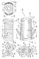
- FIG. 1is a top plan view of a first embodiment of the implant of the present invention.
- FIG. 2is a trailing end view of the implant of FIG. 1 .
- FIG. 3is a leading end view of the implant of FIG. 1 .
- FIG. 4is a side elevational view of the implant of FIG. 1, including opposed bone screws.
- FIG. 5is a trailing end view of the implant of FIG. 4 with screws and screw locks installed.
- FIG. 6Ais a side elevational view in partial cross section of a screw-lock driver.
- FIG. 6Bis a side elevational view in partial cross section of the distal end of the driver of FIG. 6A in accordance with its method of use with an implant shown as a portion in cross section, bone screw, and lock in cross section.
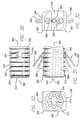
- FIG. 7is a top plan view of a second embodiment of an implant in accordance with the present invention.
- FIG. 8is a leading end view of the implant of FIG. 7 .
- FIG. 9is a trailing end view of the implant of FIG. 7 .
- FIG. 10is a side elevational view of the implant of FIG. 7, including opposed bone screws.
- FIG. 11is a trailing end view of the implant of FIG. 10 with the screws locked.
- FIG. 12is a cross sectional side view of an implant rear wall, with opposed bone screws, and a preinstallable lock in the open position.
- FIG. 13is a cross sectional side view of an implant rear wall, opposed bone screws, and with the locking element of FIG. 12 in the locked position.
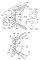
- FIG. 14is a top plan view of a third embodiment of an implant in accordance with the present invention.
- FIG. 15is a side elevation view of the implant of FIG. 14 with opposed bone engaging screws and screw lock.
- FIG. 16is a leading end view of the implant of FIG. 14 .
- FIG. 17is a trailing end view of the implant of FIG. 14 .
- FIG. 18is a trailing end view of the implant of FIG. 15 with opposed bone engaging screws and screw lock.
- FIG. 19is a side elevation view of a bone screw lock.
- FIG. 20is a side elevation view in partial cross section through the rear wall of the third embodiment implant with the bone screws and screw lock in place.
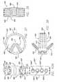
- FIG. 21is a top plan view of the fourth embodiment of an implant in accordance with the present invention.
- FIG. 22is a leading end view of the implant of FIG. 21 .
- FIG. 23is a trailing end view of the implant of FIG. 21 .
- FIG. 24is a side elevation view of the fourth embodiment implant with opposed bone engaging screws.
- FIG. 25is a trailing end view of the implant of FIG. 24 with screws and screw locks in place.
- FIG. 26is a top plan view of the screw lock of FIG. 25 .
- FIG. 27is a side elevation view in partial cross section through a portion of the rear wall of the fourth embodiment implant, with opposed bone screws, and lock.
- FIG. 28is a top plan view of an alternative lock.
- FIG. 29is a side elevation view and partial cross section through the rear wall of the fourth embodiment implant with the bone screws and alternative lock of FIG. 28 in place.
- FIG. 30is a top plan view of a fifth embodiment implant in accordance with the present invention.
- FIG. 31is a side elevation view of the implant of FIG. 30, with opposed locked bone screws and locks in place.
- FIG. 32is a trailing end view of the implant with screws and locks of FIG. 31 .
- FIG. 33is a leading end view of the fifth embodiment implant.
- FIG. 34is a side perspective view of the fifth embodiment implant.
- FIG. 35Ais a side elevation view and partial cross section through the rear wall of the fifth embodiment implant, with bone screws, and a lock positioned for engagement with a bone screw.
- FIG. 35Bis a top plan view of a bone screw.
- FIG. 35Cis a side elevation view of a bone screw head.
- FIG. 35Dis a top plan view of a screw lock.
- FIG. 36is a side elevation view and partial cross section through the rear wall of the fifth embodiment implant with locks engaged with the bone screws.
- FIG. 37is a top plan view of a sixth embodiment of an implant in accordance with the present invention, with bone screws.
- FIG. 38is a side elevation view of the sixth embodiment implant with screws of FIG. 37 .
- FIG. 39is a leading end view of the sixth embodiment implant.
- FIG. 40Ais a trailing end view of the sixth embodiment implant.
- FIG. 40Bis a trailing end view of an alternative sixth embodiment implant.
- FIG. 41is a detailed side elevation view in partial cross section of a portion of the rear of the sixth embodiment implant and the bone screw.
- FIG. 42is a detailed side elevation view in partial cross section of the rear wall of the sixth embodiment implant and an alternative screw.
- FIGS. 43, 44 , and 45are side elevation views in partial cross section showing a portion of the rear wall of one of the embodiments of the implants of the present invention and an alternative screw and lock mechanism.
- FIG. 46Ais a side perspective side view of an eighth embodiment of an implant of the present invention.
- FIG. 46Bis a side perspective view of a ninth embodiment of an implant of the present invention.
- FIG. 46Cis a side elevation view of the implant of FIG. 46 A.
- FIG. 46Dis a trailing end view of the implants of FIGS. 46A and 46B, properly inserted within a spine.
- FIG. 46Eis a side elevation view in partial cross section, showing the formation of a generally cylindrical bore across a disc space in a spine.
- FIG. 46Fis a top plan view along line 46 F— 46 F of FIG. 46 D.
- FIG. 47Ais a side elevation view in partial ghost of a screwdriver for use with the self-locking screw of FIGS. 48 and 49.
- FIG. 47Bis a bottom end view of the distal portion of the driver of FIG. 47 A.
- FIG. 48is a top plan view of the head portion of a self-locking screw of FIG. 49 .
- FIG. 49is a side elevation view of the self-locking screw of FIG. 48 .
- FIGS. 50, 51 , 52 , and 53are side elevation views in partial cutaway illustrating the method of use of the driver of FIGS. 47A and 47B and the self-locking screw of FIG. 49 in relation to the ninth embodiment of the present invention properly inserted in a spine.
- the present inventionrelates first to implants to be placed within a human spine, at least in part, within a disc space between adjacent vertebral bodies, for the purpose of fusing together those two adjacent vertebral bodies across the intermediate disc space.
- these implantsallow for the growth of bone from vertebra to adjacent vertebra through the implants themselves.
- each implantwhen inserted, will have an upper implant surface for engaging the upper of the adjacent vertebral bodies and an opposed lower implant surface for engaging the adjacent lower vertebral body. It is desirable that each of these opposed surfaces has at least one opening, and possibly a plurality of openings, sufficient in size, and in continuity with each other, to allow for the growth of bone from vertebral body to adjacent vertebral body through said implant. While not requisite, it is also desirable that these implants further be hollow to facilitate such bone growth through the implant.
- the implants of the present inventiondiffer from all prior art implants in that they are adapted to receive through their trailing ends at least a pair of appropriately sized opposed bone screws that can be directed at an appropriate angle, at least one each, into each of the adjacent vertebral bodies adjacent the disc space to be fused.
- these implants adapted to receive the opposed bone screwsare further adapted also to receive bone screw locks, or in the alternative the screws are adapted to receive locks to lock the screws to the implants to prevent the backing out of the bone screws from the implants.
- those openings and those hollowscan preferably be filled with fusion promoting substances, including substances that are osteogenic, osteo-inductive, or osteo-conductive, whether naturally occurring, or artificially produced.
- fusion promoting substancesincluding substances that are osteogenic, osteo-inductive, or osteo-conductive, whether naturally occurring, or artificially produced.
- Such substancescould include, but are not limited to, bone in any of its forms, whether naturally occurring or processed, hydroxyapatite, calcium phosphate compounds, bone morphogenetic proteins, and genetic materials coding for the production of bone.
- Various embodiments of the present inventionshow implants having a large hollow therein. While not requisite, it may be advantageous to have a large access-way to the implant hollow. By way of example, a cap may be used for closing all or part of the access-way.
- the present invention implant including the screws and locksmay be formed of any material suitable for their intended purpose. To that end, they can be made of a surgical quality metal such as titanium or one of its alloys, cobalt chrome, or any other surgical quality metal suitable for the intended purpose.
- the implantcan be made of an appropriate ceramic, be it naturally occurring or artificially produced.
- the implantalso can be formed of or include cortical bone.
- the implantcan be formed of plastics or composites, for example, a carbon fiber plastic material or bioresorbable material.
- the implantcan further comprise or be filled with, treated with, coated with, or used in combination with various fusion promoting substances, including but not limited to hydroxyapatite, calcium phosphate compounds, bone morphogenetic proteins, genetic materials coding for the production of bone, and a chemical substance to inhibit scar formation.
- various fusion promoting substancesincluding but not limited to hydroxyapatite, calcium phosphate compounds, bone morphogenetic proteins, genetic materials coding for the production of bone, and a chemical substance to inhibit scar formation.
- FIGS. 1 through 5Shown in FIGS. 1 through 5 is a first embodiment of the present invention.
- Generally cylindrical, highly perforated, hollow interbody spinal fusion implant 100has a leading end 102 and a trailing end 104 .
- Leading end 102has a threadable cap 112 having a drive aperture 114 , and holes 110 for the through growth of bone and vascular access.
- At trailing end 104is a box-like recess 118 for receiving an implant driver (not shown).
- Trailing end 104 of implant 100also has a plurality of bone holes 110 and two more specialized openings 120 which are threaded for receiving a complimentary threaded member from a driver so as to allow the driver to rigidly affix to trailing end 104 of implant 100 .
- Trailing end 104also has bone screw receiving holes 130 , which additionally could be used to receive an implant driver. It can readily be appreciated that the trailing end of this implant or any implant embodiment of the present invention in general can be adapted in a multitude of ways for cooperatively receiving an implant driver to make possible the insertion of the implant into a spine.
- Implant 100has an upper surface 106 and an opposed lower surface 108 , each being adapted for placement into contact with one of the two adjacent vertebral bodies adjacent a disc space to be fused.
- Upper and lower surfaces 106 and 108each have a plurality of openings 110 for the through growth of bone.
- the present inventionincludes any number or arrangement of openings so long as sufficient to work for the intended purpose.
- Upper and lower surfaces 106 and 108also have an opening 134 and 136 , respectively, for allowing the passage therethrough of a bone screw for further attaching implant 100 to each of the adjacent vertebral bodies.
- Openings 134 , 136are preferably shaped and formed so as to facilitate the insertion of bone screws 142 through the rear or trailing end 104 of implant 100 and in part through openings 134 , 136 .
- the heads 156 of screws 142do not pass completely through openings 134 , 136 .
- Screws 142pass out of implant 100 preferably at an angle of between 25° and 75° to the long axis of implant 100 .
- Opposed vertebral body engaging screws 142are illustrated as having the preferred, but not requisite, cancellous-type thread 148 and a pointed tip 144 with cutting flutes 146 so as to allow screws 142 to be self-tapping. While any screw useful for the intended purpose is contemplated to be within the scope of the present invention, a self-tapping screw with a cancellous-type thread pattern over a significant portion of the shaft, with a smooth shaft proximally corresponding to the portion within the implant, and a head that can be lagged against the implant is particularly preferred for its advantages.
- the screw head 156has a drive recess 154 , here shown as a hexagon.
- FIGS. 6A and 6Bshow a driver 176 for use with the first embodiment of the present invention.
- Driver 176comprises a handle 178 , having an upper handle portion 179 and a lower handle portion 181 .
- Upper handle portion 179is attached to a central shaft 180 which terminates in a hex drive tip 184 .
- Shaft 180passes coaxially through handle 178 which extends downward to form a second shaft 182 that houses shaft 180 and terminates distally in a second hexagonal tip 183 .
- An annular groove 175 in shaft 180receives a ball and spring detent 177 to hold handle 181 and contiguous shaft 182 in selective position relative to handle 179 and contiguous shaft 180 .
- hexagonal driver tip 184 of shaft 180is utilized to insert through the trailing end 104 of implant 100 bone screw 142 by means of a hex depression 154 in bone screw head 156 .
- screw 142is fully inserted through the opening 130 in trailing end 104
- the enlarged portion of the head 156is blocked from passing fully through implant 100 by a retaining flange 138 of the implant.
- it is possible to cause the vertebral body into which the threads of screw 142 are implantedto be lagged towards, that is to be compressed to, the implant surface and particularly towards trailing end 104 of implant 100 by further rotating screw 142 .
- Lock 162is circumferentially threaded with threads 172 .
- lock 162contacts trailing wall 104 of implant 100 , such that threads 172 of lock 162 can be threaded into the receiving threads 140 of implant 100 .
- opening 130is not fully threaded for its entire depth, but only sufficient to allow lock 162 to become generally flush with trailing wall 104 , at which point lock 162 can be quite rigidly tightened against the unthreaded portion of opening 130 , which acts as a stop, preventing any further movement of lock 162 into opening 130 .
- FIGS. 7 through 13show a second embodiment of the present invention.
- Implant 200though similar to implant 100 , differs from implant 100 in that the sides have been tangentially removed and the remaining upper and lower arcuate portions have been wedged apart, such that trailing end 204 is taller than the leading end 202 .
- the tangential truncation of the sidesallows two implants 200 to be placed side-by-side, such that the combined width of the two implants is significantly less than the combined height of the implants.
- upper and lower surfaces 206 , 208 from trailing end 204 to leading end 202is beneficial for inducing lordosis when implant 200 is inserted across the disc space between two adjacent vertebrae from anterior to posterior.
- the implants shown herein by way of example onlycan be modified for posterior insertion, in which case the upper and lower surfaces may be generally convergent from the leading end to the trailing end.
- Implant 200has a leading end 202 , having a plurality of holes 210 therethrough for the through growth of bone and vascular access. Implant 200 does not have a removable cap as did implant 100 , relying rather on large opening 224 which may be present on each side, or one side only to provide access to the hollow interior 226 of implant 200 for the purpose of loading implant 200 with fusion promoting substances.
- the implant upper and lower surfaces 206 and 208respectively, each have at least one and preferably a plurality of bone holes 210 , and similar to implant 100 , a series of forward facing annular ratchets for engaging the vertebral bone. Upper surface 206 and lower surface 208 have openings 234 and 236 , respectively, for conducting therethrough bone engaging screws 242 .
- Trailing end 204has a pair of opposed bone screw receiving holes 230 angled so as to direct screw 242 introduced through trailing end 204 of implant 200 .
- Holes 230receive screw 242 , which passes therethrough and into each of the adjacent vertebral bodies.
- Screw 242preferably is at an angle to the longitudinal axis of implant 200 and more preferably at an angle of from 25° to 75°.
- Implant 200has a plurality of bone holes 210 .
- a lock 262Situated intermediate to opposed bone screw receiving holes 230 is a lock 262 having a head portion 256 with a hex well 264 therein, and opposed concave portions 272 . It should be understood that various driver engaging structures useful for the intended purpose are anticipated and within the scope of the present invention.
- openings 230are fully open for receiving opposed bone screws 242 .
- lock 262can be further tightened by turning it 90 degrees until head 264 bottoms out against implant trailing end 204 , thereby allowing the locking screw to be solidly tightened to implant 200 .
- FIGS. 9 through 13it can be seen that a pair of bone screws 242 can be inserted through openings 230 in trailing end 204 of implant 200 , such that heads 256 of screws 242 are restrained within implant 200 by the contact of the enlarged head 256 against flange portion 238 of implant 200 .
- Threaded shaft 268 of lock 262threads into the rear of implant 200 .
- implant 200can be so constructed to prevent any angular freedom of screw 242 relative to implant 200 . Further, implant 200 and lock 262 can be configured to cooperate to prevent any backward motion of screw head 256 .
- FIGS. 14 through 20show a third embodiment of the present invention.
- Implant 300is generally cylindrical and hollow with a thin outer wall that is highly perforated and carries a helical thread.
- This particular thread configurationis offered by way of example only, and the invention anticipates and includes any thread suitable for the intended purpose. Further it is understood that a thread can be so formed that it becomes difficult to define the thread from the outer wall, such that the outer surface of the implant is, in essence, the peaks and valleys of the thread. It is further understood that while the thread shown here is generally continuous and helical, the thread also could be interrupted.
- Implant 300has a leading end 302 having a threadable cap 312 with a plurality of bone holes 310 and a central hex aperture 314 for receiving a driver.
- Alternative embodiment implantsmay be open at their leading ends, trailing ends, or both, or may be closeable or partially closeable with other than a threaded cap.
- Implant 300has an upper bone engaging surface 306 and an opposed lower bone engaging surface 308 .
- Intermediate upper and lower surfaces 306 and 308implant 300 has side surfaces identical to surfaces 306 and 308 . Each of these four surfaces have an opening such as 334 and 336 , allowing for the passage of bone screw 342 therethrough.
- implant 300This arrangement allows for implant 300 to be inserted into the implantation site by being threaded into the spine until fully inserted and then properly aligned by quarter-turn increments. As implant 300 is advanced with every one-quarter turn, there is the opportunity to properly align a pair of opposed bone screws 242 through upper and lower surfaces 306 and 308 . It can be appreciated that implant 300 is highly perforated with a multitude of holes 310 , situated over each of the implant surfaces, though as few as one adequately sized hole per surface could suffice.
- trailing end 304 of implant 300has a threaded central aperture 320 located within a partially rectangular recess 318 for threadably engaging an implant driver adapted to interdigit and to threadably connect thereto for rotating the implant, both clockwise and counterclockwise while simultaneously either pushing or pulling as desired by the surgeon.
- Trailing end 304has four symmetrically disposed bone screw receiving holes 330 .
- FIG. 19shows the structure of lock 362 having an enlarged head portion 366 , a threaded shaft 368 , and a shoulder 372 to allow lock 362 to be tightened against implant 300 .
- FIG. 20shows lock 362 in use, where it can be appreciated that head portion 352 of screw 342 is prevented from passing through implant 300 by retaining flange 338 at the base of hole 330 . It can also be appreciated that when lock 362 is fully tightened, portion 372 of head 366 can be tightened against implant 300 itself so as to, as previously described, allow for some convergent motion of the bone screws in the event of vertebral settling.
- FIGS. 21 through 29show a fourth embodiment of the present invention.
- Implant 400has a convex leading end 402 and an opposite trailing end 404 , here shown as having a generally straight mid-portion with radiused junctions to the side walls of implant 400 .
- trailing end 402 of implant 400could be generally convex and, still further, could be curved so as to generally conform to the contour of the anterior vertebral body in order to sit in close approximation thereto, without the need to be significantly recessed.
- trailing end 402could be curved so as to extend significantly beyond the anterior cortical margins of the vertebral bodies to be fused.
- Implant 400has opposed upper and lower vertebral body engaging surfaces 406 and 408 , respectively, which preferably have surface irregularities serving to both increase the surface area of the implant and the ability of the implant to engage the adjacent vertebral bodies, thereby enhancing their stability.
- Implant upper and lower surfaces 406 and 408have large windows or slots 424 therethrough, each in communication with the central hollow chamber 426 of the implant and each forming a direct path to its counterpart on the opposite surface through implant 400 .
- trailing end 404 of implant 400has, in addition to the plurality of bone holes 410 , two specialized common holes 428 , each containing two further holes 430 .
- Each of holes 430is adapted to receive a bone screw 442 through trailing end 404 of implant 400 at an angle such that the bone screw would be directed first through trailing end 404 , then through either one of upper or lower vertebral bone engaging surfaces 406 and 408 of implant 400 , and finally into the vertebral body itself at an angle preferably between 250 and 750 .
- Holes 430 and common hole 428are angled apart so as to assure that a pair of bone screws 442 inserted therethrough will be directed one each into each of the vertebral bodies adjacent the disc space containing implant 400 .
- Trailing end 404also has a central threaded aperture 420 for receiving a threaded member for cooperatively engaging an implant driver.
- Other ways of coupling the implant and implant drivercan be readily anticipated and are within the scope of the present invention.
- trailing end 404 of implant 400is adapted to receive a total of four bone screws 442 deployed in upwardly and downwardly projecting opposed pairs, and further to receive into common holes 440 threaded lock members 462 , preventing screws 442 from backing out.
- implant 400has a height greater at its trailing end 404 than at its leading end 402 , such that the implant itself is lordotic, or capable of inducing a lordotic angulation between adjacent vertebral bodies when inserted into the spine from an anterior to posterior approach.
- the present inventionalso includes such implants where the upper and lower surfaces 406 and 408 are parallel rather than convergent and, still further, where the upper and lower surfaces 406 and 408 are divergent from the trailing end to the leading end, for use from a posterior to anterior approach.
- Bone screws 442further serve to pull the vertebral bodies to upper and lower implant surfaces 406 and 408 so as to increase the compressive load thereon and mitigate against a loss of that compressive load or a distraction anteriorly which might otherwise occur if a patient were to bend back and forth or otherwise extend.
- the side walls of the implantalso have holes 424 therethrough to allow for vascular access and the through growth of bone.
- FIGS. 26 and 27show details of holes 430 through trailing end 404 of implant 400 in relation to lock 462 and a pair of opposed bone screw 442 .
- bone screws heads 452are sufficiently large that they are not able to pass through flange 438 and are thereby retained within the rear portion of implant 400 .
- a smooth shaft portion 450 of a lesser cross sectional dimension than hole 430which, in combination with the available space within common hole 428 between screw head 452 and lock 462 , allows for bone screw 442 to operate as a lag screw, but, nevertheless, be capable of some variability in its positioning and ability to move closer to implant 400 in the event of subsequent settling of the vertebral bodies towards implant 400 .
- lock 462takes the form of a disc with a threaded side wall 472 , capable of threadably engaging threads 472 within common hole 428 .
- Lock 462comprises a hex receiving opening 464 for rotationally driving lock 462 .
- hex opening 464 or other equivalent driver receiving configurationis the same as that of head 452 of screw 442 .
- FIGS. 28 and 29an alternative implant screw and lock arrangement is demonstrated for use with implant 400 , or as with the lock and screw configuration of FIG. 27 with any of the other embodiments of the present invention as may be appropriate.
- the implants shown hereinare by way of example only and without limitation to the various combinations and permutations of the various screw, lock, and implant configurations shown, as well as the substantial equivalent thereof which are anticipated and claimed to be within the scope of the present invention.
- Lock 461differs from lock 462 in that extending from head portion 463 is a threaded shaft 468 for threading into a threaded hole between opposed holes 430 within common hole 428 of implant 400 . Unlike the mechanism illustrated in FIG. 27 where cap 462 tightens against the internal implant wall rather than locking against the screw heads themselves, thereby permitting motion, head 463 of lock 461 tightens against heads 452 ′ of screws 442 ′. Screws 442 ′ differ from screws 442 in that the smooth proximal shaft portions 450 ′ are adapted to form an interference fit with the passageway through the rear portion of implant 400 and thereby allow the screws to have a precise trajectory while being rigidly locked to the implant. It should be appreciated then that FIGS.
- 27 and 29each teach a structure by which an implant of the present invention can be constructed so as to either cause the screws passing therethrough to have a fixed trajectory or a variable angle placement. Further taught is structure for permitting implants to either allow for, or to prevent post-deployment angular motion of the bone screws relative to the implant after the screws have been locked therein; or to allow for but one degree of freedom of the locked screws for the settling or the coming closer together of the adjacent vertebrae.
- Various ways of achieving such structuresare shown herein and may be combined in various ways with various embodiments of the implants shown or their substantial equivalents without departing from the scope of the present invention.
- FIGS. 30 through 36show a fifth embodiment of the present invention.
- Implant 500is an improvement upon the implants described in pending Michelson U.S. application Ser. No. 09/106,216 incorporated herein by reference. These implants have been adapted to have bone screw receiving holes 530 in posterior walls of trailing end 504 and, in each of the opposed upper and lower surfaces 506 and 508 , respectively, holes 534 and 536 for transmitting bone screws therethrough, respectively.
- Trailing end 504also comprises a rectangular slot 518 for engaging a rectangular member of an implant driver insertable therein.
- a threaded hole 520 located within slot 518allows the implant driver to further be secured to the implant by threadably engaging the implant therethrough. This allows the implant, when properly engaged to the driver, to be rotated either clockwise or counterclockwise and simultaneously be pushed or pulled at the discretion of the surgeon.
- implant 500is highly perforate and has holes 510 for vascular access and bone through growth through its leading end 502 , side walls, and upper and lower surfaces 506 and 508 . While trailing end 504 is herein shown lacking additional bone holes, this has been done to emphasize that such openings are only preferred, not requisite. As herein before stated, the particular shape, number, and arrangement of the holes are all within the scope of the present invention so long as they are appropriate for their intended purposes.
- Leading end 502 of implant 500is herein shown with a cap 512 , which is threaded and removable, and can be operated by a driver engaging hex opening 514 .
- Cap 512can be removed so that the hollow interior 526 of implant 500 can be compressibly loaded with bone.
- Cap 512can then be screwed to the leading end 502 so as to prevent the gross extrusion of the osteogenic materials loaded under pressure within the implant while, nevertheless, providing for vascular access to the interior of the implant and bone growth therethrough.
- cap 512may provide structural reinforcement to the implant so as to provide enhanced strength.
- Implant 500as is described in co-pending U.S. application Ser. No. 09/106,216 is adapted to be inserted on its side and then, only after being fully inserted, rotated 90 degrees so that upper and lower surfaces 506 and 508 engage each of the adjacent vertebral bodies adjacent the disc space in which the implant has been implanted for fusion.
- bone screws 542are inserted through opposed holes 530 in trailing end 504 and through holes 534 and 536 in upper and lower surfaces 506 and 508 , respectively, with one each passing into each of the vertebral bodies.
- the trailing ends of said implantsneed not have a trailing wall, but rather a generalized opening without departing from the scope of the present invention.
- bone screws 542have a head 552 and at least a partially, cancellously threaded shaft which is longitudinally cleaved to form an expansion slit 560 .
- Screws 542may be self-tapping. It may be alternatively beneficial to pre-drill an appropriate opening with a drill placed through the implant and into the vertebral body for receiving screw 542 .
- head 552is prevented from further motion forward by retaining flange 538 , and it is then possible to generate a compressive lag of the vertebral body against implant 500 with screw 542 .
- a locking member 562having a smooth shaft 568 terminating distally in tip 572 is then inserted through the drive opening in head 552 of screw 542 until portion 566 of lock 562 threadably engages within head 552 . Then as lock 562 is threaded more deeply into head 552 of screw 542 , point 572 wedges apart a conically tapered recess in the shaft of screw 542 , thereby wedging apart the two portions of the shaft.
- FIG. 35Bis a top view of bone screw 542 of FIG. 35 C.
- FIG. 35shows the crossed or Phillips type driver receiving structure of one preferred embodiment of the present invention.
- a central opening in screw 542is adapted to receive lock 562 .
- FIG. 35Dis a top view of lock 562 and shows a hex configuration of one preferred embodiment of the present invention for receiving a driver.
- Screw 542may be constructed so as to take advantage of a proximal thread portion or other enlargement beyond the root diameter of the proximal shaft which can be utilized to form a lock against rearward migration of the screw as it contacts retaining flange 538 . With or without such a feature, screw 542 can also rely on its spreadable nature to prevent backward migration of the screw.
- FIGS. 37 through 42show a sixth embodiment of the present invention.
- Implant 600may generally be round or oblong or comprised in the top view of both arcuate and linear portions, or arcuate portions of differing arcs of radii.
- upper and lower vertebrae engaging surfaces 606 and 608are but the end surfaces of the perimeter wall of the implant itself. While upper and lower surfaces 606 and 608 could be generally parallel from leading end 602 to trailing end 604 .
- trailing end 604 of implant 600is taller than leading end 602 of implant 600 , such that the opposed upper and lower surfaces 606 and 608 are converging from the trailing end to the leading end.
- implant 600which is adapted for insertion from anterior to posterior or from a position anterolaterally, is inserted, the end of the implant that will face posteriorly will be of a reduced height. This makes the insertion of the implant into the space from anterior to posterior much easier as less initial distraction of the disc space between the adjacent vertebrae is required. Further, having opposed upper and lower surfaces 606 and 608 diverge from leading end 602 to trailing end 604 allows for further restoration of the normal lordotic angulation through the disc space between the adjacent vertebrae to be fused.
- Implant 600has a plurality of holes 610 located through its perimeter wall to allow for the growth of bone and vascular access therethrough.
- Implant 600has a large central hollow 626 for containing fusion promoting substances such as bone and for allowing the fusion of vertebrae to adjacent vertebrae through the implant through area 626 and through the disc space.
- Implant 600is adapted to receive opposed bone screws 642 for engaging each of the vertebral bodies adjacent the disc space into which the implant is implanted.
- trailing end 604 of implant 600has common holes 628 having opposed bone screw receiving holes 630 .
- Holes 630are not only angled away from each other so as to face at an angle to the opposed upper and lower implant surfaces, but are further angled towards the midline of the implant as shown in FIG. 37 .
- FIG. 40Bshows trailing end 604 ′ of implant 600 ′, which is a bone ring, such as a femoral ring of cortical bone.
- Trailing end 604 ′has bone screw receiving holes 630 a - 630 d for receiving bone screws 642 therein.
- Bone screw receiving holes 630 a ′ and 630 d ′are oriented toward lower surface 608 ′ for engaging a vertebral body above implant 600 ′.
- Opposed bone screw receiving openings 630 b ′ and 630 c ′are oriented toward upper surface 606 ′ for engaging a vertebral body below implant 600 ′.
- the term “opposed”is not limited to being diametrically opposed, but includes opposite facing screw holes that are offset from one another.
- a lock or locksare provided to retain the screws when passing at least in part, and retained at least part through the openings.
- holes 630 in a preferred embodimenthave threaded walls 640 .
- bone screw 642has a head portion 652 having a threaded portion 658 for threadably engaging the threaded wall 640 in hole 630 of implant trailing end 604 .
- Screw head 652also has an enlarged head portion 654 incapable of passing through the threaded portion of hole 630 and further allowing for bone screw 642 to be securely tightened down to and against the implant, thereby locking it to the implant.
- FIG. 42illustrates an alternative design for a self-locking screw as a variation to that shown in FIG. 41 .
- Screw 642 ′has a hex drive 654 similar to screw 642 .
- screw 642 ′has a threaded shaft 648 and a threaded head portion 658 ′.
- screw 642 ′does not have an additional enlarged head portion such as portion 654 of screw 642 , but rather relies on flange portion 638 of opening 630 to stop the further progression of the screw head 652 ′ through the implant and allow for head 652 ′ to be securely tightened to the implant trailing end 604 .
- the trailing end of the implantincludes a rotatable bearing having a threaded passageway therethrough and externally, at least in part, a curved profile allowing for the bearing to be trapped within rear wall 604 of the implant while still leaving it free to rotate within a complimentary socket formed therein. Because the screw threadably engages within the bearing, which is trapped within the rear wall of the implant it can be securely tightened to the bearing while yet still being free to move.
- the bearinghas slits and the screwhead, upon final tightening, expands the bearing so that it presses against the bearing retaining socket of the rear wall, locking the screw-bearing complex to the back of the implant to the extent desired.
- the headmay slightly flare outward from distal to proximal with expansion/compression slots therethrough allowing the head to be self locking within the threaded opening of the implant or a bearing as described above.
- FIGS. 43 through 45show an alternative embodiment of a locking screw mechanism which can be adapted for use with various of the other shown and/or described implant embodiments of the present invention.
- Trailing end 704 of an implant 700has a hole 730 for accepting a bone screw 742 .
- Bone screw 742has a head portion 752 having at least a part about its perimeter a convex surface 756 having a maximum diameter.
- Bone screw receiving hole 730has a circumferential concavity portion 748 for receiving convexity portion 756 of the bone screw head.
- Bone screw head 752has internal threads 758 and a plurality of slots 760 , preferably four.
- Slots 760allow screw 742 to be driven with a cruciate type driver and allow for head 752 to sufficiently compress to be fully received within hole 730 of the implant. It can be appreciated from FIGS. 43 through 45 that screw 742 can be placed at an angle to the implant 700 . Further, once the bone screw has been fully engaged into the adjacent vertebral body, the screw can be further rotated, allowing the vertebral body to be lagged to the implant, increasing the compressive load. Once a screw has been properly placed and tightened to the extent desired by the surgeon, a locking screw 762 having a head 766 and a threaded shaft 768 may be threaded into the threaded interior of the head 752 of bone screw 742 .
- the system 43 through 45can be manufactured such that while the locking screw 762 may be lockably tightened to the bone screw 742 , and thus the backward migration of 742 from the implant prevented, the system can be designed so as to either allow for angular motion after the locking screw 762 is locked to the bone screw 742 or to prevent it.
- the function of the head in its ability to rotate and angulate within the implantis not dissimilar to the above described variation of the self locking screw and rounded bearing combination.
- FIGS. 46A through 53show an eight and ninth embodiment of the present invention. Implants 800 and 900 , which are shown in FIGS. 46A-46C can be used by themselves, or with a second of their kind, or as a complimentary pair as well shown in FIGS. 46D and 46F.
- FIGS. 46A-53show implants 800 and 900 and a series of steps useful for discussing a method of use of the present invention implants.
- Methods for inserting spinal implantsare discussed in part in issued and pending patent applications to Michelson U.S. Pat. Nos. 5,593,409, 5,741,253, 5,484,437, Ser. Nos. 08/396,414, and 08/480,904, incorporated herein by reference.
- the disc space to be usedis preferably, but not necessarily, distracted to optimal height and the vertebral bodies preferably, but not necessarily, properly aligned.
- a pair of overlapping bores, as best illustrated in FIG. 46D,are then formed across the disc space with a bone removal device, as shown in FIG. 46 E.
- the bone removal deviceis preferably a drill having a diameter greater than the height of a distracted disc space such that arc-shaped portions of bone are removed from each of the vertebral bodies adjacent the disc space to be fused.
- the overlapping boresare generally oriented from anterior to posterior and preferably stop short of the spinal canal.
- a bone removal devicesuch as a drill or mill that may be conical can be utilized to complement the tapered configuration of the implant body.
- a generally cylindrical drill DR or end millis utilized to create a generally cylindrical bore “B” for receiving the implants.
- a pair of generally cylindrical overlapping borespreferably but not necessarily, having a diameter generally corresponding to that of the root diameter of the implant proximate the leading end are formed as per.
- the implantswill come to be positioned such that the combined width of the implants at their leading ends will be less than the combined width of implants at their trailing end. That is, the implants will be angled in towards each other from anterior to posterior.
- the disc spacemay be distracted in any number of ways and held distracted during the bore formation portion of the procedure.
- Some of the preferred waysinclude the use of long distractors, short distractors, and extended outer sleeves having distractor members for placement within the disc space and between the adjacent vertebral bodies as described by Michelson in the above described applications and patents incorporated by reference herein.
- Other distractorssuch as those which attach to the vertebral bodies as by pins or screws might also be useful for the present intended purpose.
- both boresare created in overlapping fashion prior to the insertion of the first implant which in this example is implant 800 .
- Implant 800is affixed to an implant driver, which preferably engages the implant at trailing wall 804 by interdigitating with implant 800 and further binding to implant 800 by a thread such that it is possible both to rotate implant 800 in either direction and to push or pull simultaneously. While that may be achieved by having a driver which interdigitates with any of the openings into or through rear wall 804 and having a rotatable portion for threading into threaded opening 820 the present invention is not so limited and may include any driver useful for the intended purpose.
- a complementary implant 900is inserted by allowing it to rotate within the maximum circumference of implant 800 .
- Pre-tapping the bores formed across the disc space prior to the insertion of the implantsdoes not deviate from the present teaching. In a preferred embodiment, pre-tapping is not required as certain preferred embodiments of the present implants are tapered from their trailing to their leading ends and the leading ends have particularly significant thread heights making their ability to thread themselves into the bone particularly effective.
- FIGS. 46A, 46 B and 46 Dshow openings at the trailing end of the implant for receiving opposed screws that may be oriented from the implant into each of the adjacent vertebral bodies. These screws enter the implant through the trailing end and the threaded shafts of the screws pass through openings in the opposite upper and lower vertebral body engaging surfaces of the implants.
- Shown in FIGS. 50-53is a cut away through implant 900 of FIG. 46 B. This is a cross section through the mid-longitudinal axis of implant 900 and the adjacent vertebral bodies.
- FIGS. 47A and 47Bshow a screw driver 880 and FIG. 51 shows driver 880 driving a bone screw 842 through bone screw receiving hole 930 and out 842 through lower vertebrae engaging surface 908 into adjacent vertebral body V 2 .
- the present inventionincludes the use of any bone screws for this described purpose.
- structureis provided to block the bone screws from disengaging from the implant or backing out.
- the screwsmay be rigidly locked to the implant or may be prevented from backing out in a manner that still allows for some relative motion between the screws and the implant. The latter may be beneficial for anticipating and allowing for some settling of the vertebral bodies towards the disc space.
- the driver 880is assembled to the screw 842 thereby compressing the head portion of the screw.
- the screwis then introduced through the trailing end of the implant and directed into the body of one of the adjacent vertebrae passing out of an opening adapted for that purpose in one of the opposite vertebrae engaging surfaces of the implant.
- the head of the screw 842is too large to pass through the opening in the implant, and yet is free to spin against the implant itself making it possible to lag the screw, or that is to draw the body of the vertebra to the implant and to generate compressive load between the implant and the vertebral body.
- FIGS. 46A and 46Cshow a preferred embodiment of implant 800 .
- the lateral side wall and medial side wallhave a distance therebetween defining an implant width transverse to the implant height.
- the width of implant 800is less than its height along at least a portion of its length.
- the medial side wallis preferably configured to be positioned in close proximity to at least implant 900 such that the combined width of implants 800 , 900 is less than the combined height of those implants.
- Implant 800is similar to implant 900 , but differs from implant 900 in that while the lateral sides of implants 800 and 900 , respectively, are the same and in this example convex, the medial side of implant 800 has been relieved so as to allow for the convex medial side of implant 900 to protrude therein. Alternatively, the medial side of implant 800 can be relieved, in part absent, and/or concave.
- Implant 800also has at the medial side a convexity as shown by the contour of trailing support wall 804 .
- leading support wall 802may similarly be concave.
- a portion of the medial side wallis absent so as to allow for the protrusion of implant 900 therein.
- thread 922 of implant 900may have a generally constant outer diameter.
- the body of implant 900is generally conical such that it tapers from the larger trailing end 904 to the smaller leading end 902 , the height of thread 922 relative to the body increases from trailing end 904 to leading end 902 .
- the outer diameter of the threadsremains generally constant, the height of the thread increases from trailing end 904 to leading end 902 . This is similarly true for implant 800 .
- the start of the external thread about the perimeter of the implantis precisely indexed such that if the surgeon knows the depth of the bore created, he may select an implant of the desired length being less than or equal to the depth of the bore created and by starting the insertion of the implant in a preferred rotational alignment such as the desired final rotational alignment the implant when threaded in fully will come to rest such that trailing end 804 , 904 will be correctly rotationally aligned so that the screw receiving holes 834 , 836 , 934 , 936 will be oriented correctly towards the adjacent vertebral bodies while the profile of trailing ends 804 , 904 will correspond to the contour of the anterior vertebral body.
- the start of the thread at the implant leading endcould be indexed such that the implant could be introduced rotationally oriented exactly as desired for the final positioning. Then, by making ten complete revolutions of three millimeters each the implant would assuredly come to rest with trailing wall 804 appropriately oriented and either be flush with the anterior vertebral cortices, or minimally counter-sunk to exactly the extent to which the surgeon caused the implant to enter the bore prior to initiating rotation.
- trailing end 804 of implant 800could be rotationally asymmetrical, but nevertheless be symmetrical from side-to-side, such that each of the sides of the implant would be less protuberant posteriorly than a point along the mid-longitudinal axis such that the implant could be correctly inserted in increments of less than or equal to 180 degrees of rotation.
- screw 842has a threaded shaft 848 having a leading end 844 , a tip 846 , and an opposite trailing end 852 .
- Shaft 848has a thread form for engaging bone.
- Trailing end 852has a screw head having an enlarged portion 856 having a diameter greater than the outer diameter of the threaded portion of shaft 848 .
- the screw headhas a cruciate recess 861 for receiving the end 890 of screw driver 880 .
- FIG. 46Bshows a front view of an embodiment of the present invention with implants 800 , 900 properly implanted across the disc space between adjacent vertebral bodies V 1 and V 2 .
- Openings 820 , 920also are adapted to receive a screw device to link the implant to other implants, to a staple, or to receive a locking screw to lock bone engaging screws to the implant as disclosed in Michelson U.S. patent application Ser. No. 08/926,334 incorporated herein by reference.
- trailing ends 804 and 904 of implants 800 and 900respectively, preferably are rotationally asymmetrical about the longitudinal axes of the implants such that the designated medial side of each of the implants has a length greater than the lateral sides of the same implants.
- Trailing ends 804 , 904preferably are structured to have a lesser length along their lateral sides than through the mid-longitudinal axis and are preferably contoured so as to sit on the anterior rims of the vertebral bodies without protruding dangerously therefrom as set forth in pending Michelson application Ser. No. 09/263,266 incorporated herein by reference.
- the trailing ends of the implantscan have a maximum length along the mid-longitudinal axis greater than the length along either of the medial and lateral sidewalls so that the bone screw receiving holes can be oriented towards the adjacent vertebral bodies in half rotation increments rather than requiring a full rotation. While for implant 900 this would require no other modification than as described for the trailing end, in regard to implant 800 each of the lateral and medial side walls would have to be relieved to allow for the receipt of the perimeter of implant 900 within the maximum perimeter of implant 800 .
- the screws of the present inventionhave the following preferred size.
- the screwsWhen for use in the lumbar spine, the screws have at least partially threaded shafts having outer diameters (major diameter) not less than 4.8 mm and not greater than 10 mm with 6 mm to 8 mm generally preferred.
- a preferred root diameteris at least 1.5 mm less than the outer diameter and most preferably 2.5 mm to 5 mm.
- a length of from 10 mm to 40 mmis preferred with 20 mm to 30 mm being more preferred.
- a length of from 10-50 mmis preferred with 25-35 mm being more preferred.
- the screwspreferably have head portions having an outside dimension generally equal to or greater than the outer diameter of the thread of the threaded shaft.
- headhas an outwardly facing machine thread and the shaft has a cancellous thread with the turns or pitch of the thread being spaced apart to exceed the wall thickness of that portion of the implant adapted to retain the screw head.
- the screwspreferably have pointed leading ends and are self tapping with cutting flutes and have an interrupted thread at their leading end.
- the screwspreferably have a smooth shaft portion proximally near the head. All screws preferably have at their trailing ends adapted for cooperatively engaging a screw driver.
- Screws used in the cervical spinevary from screws used in the lumbar spine in that a preferred major diameter is 3.5-5.5 mm with 4.0 mm to 5.0 mm being more preferred. A preferred length is from 8-20 mm with 12-16 mm being more preferred.
- Preferred screws for use in the thoracic spinevary from screws used in the lumbar and cervical spine in that a preferred thread has an outer diameter from 4-8 mm with 5-7 mm being more preferred.
- the screwshaving a length of from 10 mm to 30 mm with a length of approximately 20 mm plus or minus 5 mm being more preferred.
Landscapes
- Health & Medical Sciences (AREA)
- Orthopedic Medicine & Surgery (AREA)
- Engineering & Computer Science (AREA)
- Biomedical Technology (AREA)
- Neurology (AREA)
- Life Sciences & Earth Sciences (AREA)
- Public Health (AREA)
- Heart & Thoracic Surgery (AREA)
- Veterinary Medicine (AREA)
- Animal Behavior & Ethology (AREA)
- General Health & Medical Sciences (AREA)
- Surgery (AREA)
- Transplantation (AREA)
- Cardiology (AREA)
- Oral & Maxillofacial Surgery (AREA)
- Vascular Medicine (AREA)
- Molecular Biology (AREA)
- Medical Informatics (AREA)
- Nuclear Medicine, Radiotherapy & Molecular Imaging (AREA)
- Physical Education & Sports Medicine (AREA)
- Prostheses (AREA)
Abstract
Description
This application claims priority to application Serial No. 60/132,665 filed May 5, 1999 and application Serial No. 60/133,214 filed May 7, 1999, both of which are incorporated by reference herein.
1. Field of the Invention
The present invention relates generally to interbody spinal fusion implants. Implants, artificial or natural, are placed at least in part within a disc space and in contact with each of the vertebral bodies adjacent that disc space for spacing apart and aligning those vertebral bodies and for allowing for the growth of bone in continuity from vertebral body to adjacent vertebral body through said implant.
2. Description of the Related Art
Some of the degenerative conditions that affect the spine may be so severe as to require surgical intervention. For example, a disc herniation may compress the spinal cord and/or nerve roots and cause pain, loss of function, and even complete paralysis of the legs with loss of bowel and bladder control. The correct treatment for such conditions is the removal of the offending discal tissue.
Sometimes, for a variety of reasons including the removal of disc material, the spine may become unstable (too much motion) at any given level. Historically, this has been treated by fusion, the joining together permanently of the unstable vertebrae via a bridge of bone so as to eliminate all motion along that portion of the spine.
To achieve fusion, bone or bone like substances are applied between two (or more) separate and distinct bones to induce bony bridging therebetween. When such procedures are successfully performed between vertebral bodies, an interbody fusion results. The shared bone in the area previously occupied by an intervertebral disc is referred to as an interbody fusion.
When a spinal surgeon seeks to perform an interbody fusion, the spine may be accessed from a variety of directions. If the surgeon elects to approach the spine anteriorly, this generally requires severing and/or removing substantial portions of the anterior longitudinal ligament over the operated area. The anterior longitudinal ligament is positioned along the anterior spinal surface and prevents hyperextension of the spine as an individual bends backward. Because the anterior longitudinal ligament covers the anterior spinal surface, the surgeon must cut through this tough ligament to access the disc space therebelow, compromising the stability of the spine. Specifically, the anterior longitudinal ligament is generally lax, except when an individual leans backward, then the ligament acts as a tension band resisting elongation. If the anterior longitudinal ligament is damaged, there is no check on that spinal movement and the vertebral bodies may detrimentally angulate.
Without a functional anterior longitudinal ligament, the patient may damage an implant(s) placed into a disc space to facilitate interbody fusion of the adjacent vertebral bodies. The implant may crush into or erode into, the adjacent vertebral bodies as the disc space opens anteriorly and crushes down posteriorly when the patient bends backwards. The vertebrae may rock together posteriorly and open anteriorly, thus dislodging the implant. Accordingly, in at least any spinal surgery requiring access to the disc space through the anterior longitudinal ligament, there is a need to functionally reconstruct the anterior longitudinal ligament to preserve stability about the disc space to be fused. Stability of the spine across the disc space to be fused is beneficial for achieving fusion.
In order to perform anterior interbody spinal fusion, a significant amount of disc material is removed from the interspace to be fused. After removing the disc material, the disc space is filled with an implant, which generally includes bone or bone in combination with a reinforcing structure, such as an artificial (other than bone) interbody spinal fusion implant. Because of the forces and motions occurring through the spine, it is not uncommon for such implants to dislodge, thereby causing a failure of surgery and possibly warranting further surgery to correct the problem and to again attempt interbody fusion.
Metal hardware outside the disc space affixed anteriorly to the vertebral bodies adjacent the disc space to be fused is useful to ensure the stability of the spine during the fusion period. Those skilled in the art have shown great reluctance to utilize such hardware because of the potential for the hardware to impinge on vital body structures, such as the aorta, vena cava, or great iliac vessels. The rupture of any of these body structures could cause sudden death. A rupture may occur late after surgery due to the pulsing of an artery against the metal hardware resulting in the eventual erosion and rupture of the artery. Further, metal applied to the outer surfaces of the vertebral bodies may become loose. For example, a screw may back out from repeated bodily movements, leading to the above-described situation.
Therefore, there is a need for an implant that is resistant to dislodgment and functionally substitutes for the anterior longitudinal ligament at the level to be fused, without protruding from the spine.
According to the present invention, an improved interbody spinal fusion implant is provided. The implant has structure that functionally substitutes for a damaged anterior longitudinal ligament following an anterior implant procedure. The present invention is not limited to functionally reconstructing the anterior longitudinal ligament, however, and also is useful for increasing the stability of the implant, decreasing the mobility of the adjacent vertebrae to be fused together, increasing and more evenly distributing the compressive loads across the fusion site, and mitigating the generation of undesirable localized excessive peak loads; and thus is of great benefit for implants inserted into the disc space posteriorly or laterally as well as anteriorly.
Existing interbody spinal fusion implants do not adequately addresses the above described broad needs or the need to functionally reconstruct the anterior longitudinal ligament, which to be useful must be done in a way that can assure the safety of the great blood vessels. The present teachings provide the structure by which implants may be constructed or existing implants may be modified to take advantage of the improvements of the present invention.
Implants that may be modified to incorporate the present teaching are those interbody implants adapted for placement within a disc space of the human spine between adjacent vertebral bodies, which implants have surfaces for contacting each of the adjacent vertebral bodies and structure therethrough, such as opening(s), to allow for the growth of bone from vertebra to vertebra through the implant. Such implants, inter alia, include generally rectangular implants such as disclosed in U.S. Pat. No. 5,776,199 to Michelson; lordotic interbody spinal fusion implants such as disclosed in U.S. Pat. No. 5,609,635 to Michelson; threaded cylindrical spinal implants such as disclosed in U.S. Pat. No. 5,860,973 to Michelson; thin-walled, perforated, threaded, hollow cylindrical implants such as disclosed in U.S. Pat. No. 5,015,247 to Michelson; and thin-walled, multiperforated partially cylindrical and cylindrical implants such as disclosed in U.S. Pat. No. 5,785,710 to Michelson. U.S. Pat. Nos. 5,776,199; 5,609,635; 5,860,973; 5,015,247; and 5,785,710 are incorporated herein by reference. The present invention and any or all of its parts may be constructed out of any material appropriate for the described purpose including, but not limited to, cortical bone, surgical quality metals, ceramics, bioresorbable and non-resorbable plastics and composites.
FIG. 1 is a top plan view of a first embodiment of the implant of the present invention.
FIG. 2 is a trailing end view of the implant of FIG.1.
FIG. 3 is a leading end view of the implant of FIG.1.
FIG. 4 is a side elevational view of the implant of FIG. 1, including opposed bone screws.
FIG. 5 is a trailing end view of the implant of FIG. 4 with screws and screw locks installed.
FIG. 6A is a side elevational view in partial cross section of a screw-lock driver.
FIG. 6B is a side elevational view in partial cross section of the distal end of the driver of FIG. 6A in accordance with its method of use with an implant shown as a portion in cross section, bone screw, and lock in cross section.
FIG. 7 is a top plan view of a second embodiment of an implant in accordance with the present invention.
FIG. 8 is a leading end view of the implant of FIG.7.
FIG. 9 is a trailing end view of the implant of FIG.7.
FIG. 10 is a side elevational view of the implant of FIG. 7, including opposed bone screws.
FIG. 11 is a trailing end view of the implant of FIG. 10 with the screws locked.
FIG. 12 is a cross sectional side view of an implant rear wall, with opposed bone screws, and a preinstallable lock in the open position.
FIG. 13 is a cross sectional side view of an implant rear wall, opposed bone screws, and with the locking element of FIG. 12 in the locked position.
FIG. 14 is a top plan view of a third embodiment of an implant in accordance with the present invention.
FIG. 15 is a side elevation view of the implant of FIG. 14 with opposed bone engaging screws and screw lock.
FIG. 16 is a leading end view of the implant of FIG.14.
FIG. 17 is a trailing end view of the implant of FIG.14.
FIG. 18 is a trailing end view of the implant of FIG. 15 with opposed bone engaging screws and screw lock.
FIG. 19 is a side elevation view of a bone screw lock.
FIG. 20 is a side elevation view in partial cross section through the rear wall of the third embodiment implant with the bone screws and screw lock in place.
FIG. 21 is a top plan view of the fourth embodiment of an implant in accordance with the present invention.
FIG. 22 is a leading end view of the implant of FIG.21.
FIG. 23 is a trailing end view of the implant of FIG.21.
FIG. 24 is a side elevation view of the fourth embodiment implant with opposed bone engaging screws.
FIG. 25 is a trailing end view of the implant of FIG. 24 with screws and screw locks in place.
FIG. 26 is a top plan view of the screw lock of FIG.25.
FIG. 27 is a side elevation view in partial cross section through a portion of the rear wall of the fourth embodiment implant, with opposed bone screws, and lock.
FIG. 28 is a top plan view of an alternative lock.
FIG. 29 is a side elevation view and partial cross section through the rear wall of the fourth embodiment implant with the bone screws and alternative lock of FIG. 28 in place.
FIG. 30 is a top plan view of a fifth embodiment implant in accordance with the present invention.
FIG. 31 is a side elevation view of the implant of FIG. 30, with opposed locked bone screws and locks in place.
FIG. 32 is a trailing end view of the implant with screws and locks of FIG.31.
FIG. 33 is a leading end view of the fifth embodiment implant.
FIG. 34 is a side perspective view of the fifth embodiment implant.
FIG. 35A is a side elevation view and partial cross section through the rear wall of the fifth embodiment implant, with bone screws, and a lock positioned for engagement with a bone screw.
FIG. 35B is a top plan view of a bone screw.
FIG. 35C is a side elevation view of a bone screw head.
FIG. 35D is a top plan view of a screw lock.
FIG. 36 is a side elevation view and partial cross section through the rear wall of the fifth embodiment implant with locks engaged with the bone screws.
FIG. 37 is a top plan view of a sixth embodiment of an implant in accordance with the present invention, with bone screws.
FIG. 38 is a side elevation view of the sixth embodiment implant with screws of FIG.37.
FIG. 39 is a leading end view of the sixth embodiment implant.
FIG. 40A is a trailing end view of the sixth embodiment implant.
FIG. 40B is a trailing end view of an alternative sixth embodiment implant.
FIG. 41 is a detailed side elevation view in partial cross section of a portion of the rear of the sixth embodiment implant and the bone screw.
FIG. 42 is a detailed side elevation view in partial cross section of the rear wall of the sixth embodiment implant and an alternative screw.
FIGS. 43,44, and45 are side elevation views in partial cross section showing a portion of the rear wall of one of the embodiments of the implants of the present invention and an alternative screw and lock mechanism.
FIG. 46A is a side perspective side view of an eighth embodiment of an implant of the present invention.
FIG. 46B is a side perspective view of a ninth embodiment of an implant of the present invention.
FIG. 46C is a side elevation view of the implant of FIG.46A.
FIG. 46D is a trailing end view of the implants of FIGS. 46A and 46B, properly inserted within a spine.
FIG. 46E is a side elevation view in partial cross section, showing the formation of a generally cylindrical bore across a disc space in a spine.
FIG. 46F is a top plan view alongline 46F—46F of FIG.46D.
FIG. 47A is a side elevation view in partial ghost of a screwdriver for use with the self-locking screw of FIGS. 48 and 49.
FIG. 47B is a bottom end view of the distal portion of the driver of FIG.47A.
FIG. 48 is a top plan view of the head portion of a self-locking screw of FIG.49.
FIG. 49 is a side elevation view of the self-locking screw of FIG.48.
FIGS. 50,51,52, and53 are side elevation views in partial cutaway illustrating the method of use of the driver of FIGS. 47A and 47B and the self-locking screw of FIG. 49 in relation to the ninth embodiment of the present invention properly inserted in a spine.
The present invention relates first to implants to be placed within a human spine, at least in part, within a disc space between adjacent vertebral bodies, for the purpose of fusing together those two adjacent vertebral bodies across the intermediate disc space. Though not so limited, it is desirable that these implants allow for the growth of bone from vertebra to adjacent vertebra through the implants themselves. To this end, each implant, when inserted, will have an upper implant surface for engaging the upper of the adjacent vertebral bodies and an opposed lower implant surface for engaging the adjacent lower vertebral body. It is desirable that each of these opposed surfaces has at least one opening, and possibly a plurality of openings, sufficient in size, and in continuity with each other, to allow for the growth of bone from vertebral body to adjacent vertebral body through said implant. While not requisite, it is also desirable that these implants further be hollow to facilitate such bone growth through the implant.
The implants of the present invention differ from all prior art implants in that they are adapted to receive through their trailing ends at least a pair of appropriately sized opposed bone screws that can be directed at an appropriate angle, at least one each, into each of the adjacent vertebral bodies adjacent the disc space to be fused. In a further novel teaching of the present invention, these implants adapted to receive the opposed bone screws are further adapted also to receive bone screw locks, or in the alternative the screws are adapted to receive locks to lock the screws to the implants to prevent the backing out of the bone screws from the implants.
To the extent that such implants are hollow and have openings through the surfaces, those openings and those hollows can preferably be filled with fusion promoting substances, including substances that are osteogenic, osteo-inductive, or osteo-conductive, whether naturally occurring, or artificially produced. Such substances could include, but are not limited to, bone in any of its forms, whether naturally occurring or processed, hydroxyapatite, calcium phosphate compounds, bone morphogenetic proteins, and genetic materials coding for the production of bone. Various embodiments of the present invention show implants having a large hollow therein. While not requisite, it may be advantageous to have a large access-way to the implant hollow. By way of example, a cap may be used for closing all or part of the access-way.
The present invention implant including the screws and locks may be formed of any material suitable for their intended purpose. To that end, they can be made of a surgical quality metal such as titanium or one of its alloys, cobalt chrome, or any other surgical quality metal suitable for the intended purpose. The implant can be made of an appropriate ceramic, be it naturally occurring or artificially produced. The implant also can be formed of or include cortical bone. The implant can be formed of plastics or composites, for example, a carbon fiber plastic material or bioresorbable material. The implant can further comprise or be filled with, treated with, coated with, or used in combination with various fusion promoting substances, including but not limited to hydroxyapatite, calcium phosphate compounds, bone morphogenetic proteins, genetic materials coding for the production of bone, and a chemical substance to inhibit scar formation.
Shown in FIGS. 1 through 5 is a first embodiment of the present invention. Generally cylindrical, highly perforated, hollow interbodyspinal fusion implant 100 has aleading end 102 and a trailingend 104. Leadingend 102 has athreadable cap 112 having adrive aperture 114, and holes110 for the through growth of bone and vascular access. At trailingend 104 is a box-like recess 118 for receiving an implant driver (not shown). Trailingend 104 ofimplant 100 also has a plurality of bone holes110 and two morespecialized openings 120 which are threaded for receiving a complimentary threaded member from a driver so as to allow the driver to rigidly affix to trailingend 104 ofimplant 100. Trailingend 104 also has bonescrew receiving holes 130, which additionally could be used to receive an implant driver. It can readily be appreciated that the trailing end of this implant or any implant embodiment of the present invention in general can be adapted in a multitude of ways for cooperatively receiving an implant driver to make possible the insertion of the implant into a spine.
Opposed vertebralbody engaging screws 142 are illustrated as having the preferred, but not requisite, cancellous-type thread 148 and apointed tip 144 with cuttingflutes 146 so as to allowscrews 142 to be self-tapping. While any screw useful for the intended purpose is contemplated to be within the scope of the present invention, a self-tapping screw with a cancellous-type thread pattern over a significant portion of the shaft, with a smooth shaft proximally corresponding to the portion within the implant, and a head that can be lagged against the implant is particularly preferred for its advantages. Thescrew head 156 has adrive recess 154, here shown as a hexagon.
FIGS. 6A and 6B show adriver 176 for use with the first embodiment of the present invention.Driver 176 comprises ahandle 178, having anupper handle portion 179 and alower handle portion 181.Upper handle portion 179 is attached to acentral shaft 180 which terminates in ahex drive tip 184.Shaft 180 passes coaxially throughhandle 178 which extends downward to form asecond shaft 182 that housesshaft 180 and terminates distally in a secondhexagonal tip 183. Anannular groove 175 inshaft 180 receives a ball andspring detent 177 to holdhandle 181 andcontiguous shaft 182 in selective position relative to handle179 andcontiguous shaft 180.
As can be appreciated from FIG. 6B, in usehexagonal driver tip 184 ofshaft 180 is utilized to insert through the trailingend 104 ofimplant 100bone screw 142 by means of ahex depression 154 inbone screw head 156. Oncescrew 142 is fully inserted through theopening 130 in trailingend 104, the enlarged portion of thehead 156 is blocked from passing fully throughimplant 100 by a retainingflange 138 of the implant. At this point, it is possible to cause the vertebral body into which the threads ofscrew 142 are implanted to be lagged towards, that is to be compressed to, the implant surface and particularly towards trailingend 104 ofimplant 100 by further rotatingscrew 142. Once the optimal compression has been obtained as determined by the surgeon at the time of surgery, withtip 184 ofshaft 180 still engaged withscrew head 156 withindepression 154, the surgeon then utilizesshaft 180 as a centering post and separates handleportion 181 fromhandle portion 179 by pressing downward. This downward pressure causes the detent ball andspring 177 to be forced out ofannular groove 175 and allowssecond shaft 182 to move downward, taking with it lock162 which was engaged todriver 176 prior to engagingdriver 176 tobone screw 142.
Alternatively, by any number of structural configurations, such as by way of an example an interference fit betweenscrew head 156 andimplant opening 130, or by way of more deeply threading theopening 130, or by flattening the top of the screws and making the circumferential perimeter flush to the lock, or by allowing the lock to contact the screw head, later motion of the screw can be prevented. Said differently, while the present example shows how to allow for variability in the screw's placement and provides for later movement of the screw as might occur with settling, in the alternative, the path of the screw through the implant can be rather narrowly defined, and any angular motion of the screw relative to the implant can be prevented.
FIGS. 7 through 13 show a second embodiment of the present invention.Implant 200, though similar toimplant 100, differs fromimplant 100 in that the sides have been tangentially removed and the remaining upper and lower arcuate portions have been wedged apart, such that trailingend 204 is taller than theleading end 202. The tangential truncation of the sides allows twoimplants 200 to be placed side-by-side, such that the combined width of the two implants is significantly less than the combined height of the implants.
The convergence of upper andlower surfaces end 204 to leadingend 202 is beneficial for inducing lordosis whenimplant 200 is inserted across the disc space between two adjacent vertebrae from anterior to posterior. Without in anyway departing from the present invention, the implants shown herein by way of example only, can be modified for posterior insertion, in which case the upper and lower surfaces may be generally convergent from the leading end to the trailing end.
As shown in FIGS. 9 and 12, whenlock 262 is one-quarter turn short of being fully tightened,openings 230 are fully open for receiving opposed bone screws242.
As shown in FIGS. 11 and 13, once opposed bone screws242 have been installed, lock262 can be further tightened by turning it 90 degrees untilhead 264 bottoms out againstimplant trailing end 204, thereby allowing the locking screw to be solidly tightened toimplant 200.
In FIGS. 9 through 13, it can be seen that a pair of bone screws242 can be inserted throughopenings 230 in trailingend 204 ofimplant 200, such that heads256 ofscrews 242 are restrained withinimplant 200 by the contact of the enlarged head256 againstflange portion 238 ofimplant 200. Threadedshaft 268 oflock 262 threads into the rear ofimplant 200.
It can be noted in FIGS. 11 and 13 that whilescrews 242 have freedom to move closer together to allow for settling,screws 242 cannot back out ofimplant 200 withlock 262 in place. As previously discussed, while this is considered preferable,implant 200 can be so constructed to prevent any angular freedom ofscrew 242 relative to implant200. Further,implant 200 and lock262 can be configured to cooperate to prevent any backward motion of screw head256.
FIGS. 14 through 20 show a third embodiment of the present invention.Implant 300 is generally cylindrical and hollow with a thin outer wall that is highly perforated and carries a helical thread. This particular thread configuration is offered by way of example only, and the invention anticipates and includes any thread suitable for the intended purpose. Further it is understood that a thread can be so formed that it becomes difficult to define the thread from the outer wall, such that the outer surface of the implant is, in essence, the peaks and valleys of the thread. It is further understood that while the thread shown here is generally continuous and helical, the thread also could be interrupted.
With attention to FIGS. 17 and 18, it can be appreciated that trailingend 304 ofimplant 300 has a threadedcentral aperture 320 located within a partiallyrectangular recess 318 for threadably engaging an implant driver adapted to interdigit and to threadably connect thereto for rotating the implant, both clockwise and counterclockwise while simultaneously either pushing or pulling as desired by the surgeon. Trailingend 304 has four symmetrically disposed bonescrew receiving holes 330. Once a pair of opposed bone screws342 have been inserted through trailingend 304 ofimplant 300 and into the adjacent vertebral bodies and sufficiently tightened,lock 362 is inserted into threadedaperture 320 by means of a driver placed into hex well364 and then tightened down to the back ofimplant 300. A pair of unused bone screw holes are then available as bone holes similar to310. FIG.19 shows the structure oflock 362 having anenlarged head portion 366, a threadedshaft 368, and ashoulder 372 to allowlock 362 to be tightened againstimplant 300.
FIG. 20 shows lock362 in use, where it can be appreciated thathead portion 352 ofscrew 342 is prevented from passing throughimplant 300 by retainingflange 338 at the base ofhole 330. It can also be appreciated that whenlock 362 is fully tightened,portion 372 ofhead 366 can be tightened againstimplant 300 itself so as to, as previously described, allow for some convergent motion of the bone screws in the event of vertebral settling.
FIGS. 21 through 29 show a fourth embodiment of the present invention.Implant 400 has a convexleading end 402 and an opposite trailingend 404, here shown as having a generally straight mid-portion with radiused junctions to the side walls ofimplant 400. In the alternative, trailingend 402 ofimplant 400 could be generally convex and, still further, could be curved so as to generally conform to the contour of the anterior vertebral body in order to sit in close approximation thereto, without the need to be significantly recessed. In another alternative, trailingend 402 could be curved so as to extend significantly beyond the anterior cortical margins of the vertebral bodies to be fused.
Both leadingend 402 and trailingend 404 ofimplant 400 are highly perforate to allow for vascular access tohollow interior 426 ofimplant 400, and to allow for the growth of bone therethrough. While the present invention does not require the presence of such openings, these openings are considered highly desirable. Any variation in particular configuration of such openings, or their arrangement, and number, so long as useful for the intended purpose, are also within the scope of the present invention.Implant 400 has opposed upper and lower vertebralbody engaging surfaces lower surfaces slots 424 therethrough, each in communication with the centralhollow chamber 426 of the implant and each forming a direct path to its counterpart on the opposite surface throughimplant 400.
As shown in FIGS. 23 and 25, trailingend 404 ofimplant 400 has, in addition to the plurality of bone holes410, two specializedcommon holes 428, each containing twofurther holes 430. Each ofholes 430 is adapted to receive abone screw 442 through trailingend 404 ofimplant 400 at an angle such that the bone screw would be directed first through trailingend 404, then through either one of upper or lower vertebralbone engaging surfaces implant 400, and finally into the vertebral body itself at an angle preferably between250 and750.Holes 430 andcommon hole 428 are angled apart so as to assure that a pair of bone screws442 inserted therethrough will be directed one each into each of the vertebral bodies adjacent the discspace containing implant 400. Trailingend 404 also has a central threadedaperture 420 for receiving a threaded member for cooperatively engaging an implant driver. Other ways of coupling the implant and implant driver can be readily anticipated and are within the scope of the present invention.
As can be appreciated from FIG. 25, trailingend 404 ofimplant 400 is adapted to receive a total of fourbone screws 442 deployed in upwardly and downwardly projecting opposed pairs, and further to receive intocommon holes 440 threadedlock members 462, preventingscrews 442 from backing out.
As can be appreciated from FIG. 24,implant 400 has a height greater at its trailingend 404 than at itsleading end 402, such that the implant itself is lordotic, or capable of inducing a lordotic angulation between adjacent vertebral bodies when inserted into the spine from an anterior to posterior approach. The present invention also includes such implants where the upper andlower surfaces lower surfaces
When the implant as shown in FIG. 24 is inserted from anterior to posterior between the adjacent vertebral bodies, any tendency forimplant 400 to back out of the implantation site created across the disc space due to the wedge-shaped contour of the implant is resisted by both theforward facing ratchetings 422 and the trajectory ofscrews 442. Bone screws442 further serve to pull the vertebral bodies to upper and lower implant surfaces406 and408 so as to increase the compressive load thereon and mitigate against a loss of that compressive load or a distraction anteriorly which might otherwise occur if a patient were to bend back and forth or otherwise extend. Consistent with the preferred, highly perforate nature ofimplant 400, the side walls of the implant also haveholes 424 therethrough to allow for vascular access and the through growth of bone.
FIGS. 26 and 27 show details ofholes 430 through trailingend 404 ofimplant 400 in relation to lock462 and a pair ofopposed bone screw 442. In this example, bone screws heads452 are sufficiently large that they are not able to pass throughflange 438 and are thereby retained within the rear portion ofimplant 400. Immediately distal toheads 452 ofscrews 442 is asmooth shaft portion 450 of a lesser cross sectional dimension thanhole 430 which, in combination with the available space withincommon hole 428 betweenscrew head 452 and lock462, allows forbone screw 442 to operate as a lag screw, but, nevertheless, be capable of some variability in its positioning and ability to move closer to implant400 in the event of subsequent settling of the vertebral bodies towardsimplant 400. In this embodiment,lock 462 takes the form of a disc with a threadedside wall 472, capable of threadably engagingthreads 472 withincommon hole 428.Lock 462 comprises ahex receiving opening 464 for rotationally drivinglock 462. In a preferred variation, hex opening464 or other equivalent driver receiving configuration, is the same as that ofhead 452 ofscrew 442.
Turning now to FIGS. 28 and 29, an alternative implant screw and lock arrangement is demonstrated for use withimplant 400, or as with the lock and screw configuration of FIG. 27 with any of the other embodiments of the present invention as may be appropriate. To that end, it should be appreciated that the implants shown herein are by way of example only and without limitation to the various combinations and permutations of the various screw, lock, and implant configurations shown, as well as the substantial equivalent thereof which are anticipated and claimed to be within the scope of the present invention.
FIGS. 30 through 36 show a fifth embodiment of the present invention.Implant 500 is an improvement upon the implants described in pending Michelson U.S. application Ser. No. 09/106,216 incorporated herein by reference. These implants have been adapted to have bonescrew receiving holes 530 in posterior walls of trailingend 504 and, in each of the opposed upper andlower surfaces end 504 also comprises arectangular slot 518 for engaging a rectangular member of an implant driver insertable therein. A threadedhole 520 located withinslot 518 allows the implant driver to further be secured to the implant by threadably engaging the implant therethrough. This allows the implant, when properly engaged to the driver, to be rotated either clockwise or counterclockwise and simultaneously be pushed or pulled at the discretion of the surgeon.
While not requisite, in a preferred embodiment,implant 500 is highly perforate and hasholes 510 for vascular access and bone through growth through itsleading end 502, side walls, and upper andlower surfaces end 504 is herein shown lacking additional bone holes, this has been done to emphasize that such openings are only preferred, not requisite. As herein before stated, the particular shape, number, and arrangement of the holes are all within the scope of the present invention so long as they are appropriate for their intended purposes.
Leadingend 502 ofimplant 500 is herein shown with acap 512, which is threaded and removable, and can be operated by a driver engaginghex opening 514.Cap 512 can be removed so that thehollow interior 526 ofimplant 500 can be compressibly loaded with bone.Cap 512 can then be screwed to theleading end 502 so as to prevent the gross extrusion of the osteogenic materials loaded under pressure within the implant while, nevertheless, providing for vascular access to the interior of the implant and bone growth therethrough. Further,cap 512 may provide structural reinforcement to the implant so as to provide enhanced strength.
Upper andlower surfaces implant 500 have a series oftransverse fins 522 and interposed therebetween a plurality of bone slots andbone holes 510 for the growth of bone therethrough.Implant 500 as is described in co-pending U.S. application Ser. No. 09/106,216 is adapted to be inserted on its side and then, only after being fully inserted, rotated90 degrees so that upper andlower surfaces implant 500 has been properly inserted, bone screws542 are inserted through opposedholes 530 in trailingend 504 and throughholes lower surfaces
As shown in FIGS. 35A-36, bone screws542 have ahead 552 and at least a partially, cancellously threaded shaft which is longitudinally cleaved to form anexpansion slit 560.Screws 542 may be self-tapping. It may be alternatively beneficial to pre-drill an appropriate opening with a drill placed through the implant and into the vertebral body for receivingscrew 542. Whenscrew 542 has been fully inserted,head 552 is prevented from further motion forward by retainingflange 538, and it is then possible to generate a compressive lag of the vertebral body againstimplant 500 withscrew 542. A lockingmember 562, having asmooth shaft 568 terminating distally intip 572 is then inserted through the drive opening inhead 552 ofscrew 542 untilportion 566 oflock 562 threadably engages withinhead 552. Then aslock 562 is threaded more deeply intohead 552 ofscrew 542,point 572 wedges apart a conically tapered recess in the shaft ofscrew 542, thereby wedging apart the two portions of the shaft.
FIG. 35B is a top view ofbone screw 542 of FIG.35C. FIG. 35 shows the crossed or Phillips type driver receiving structure of one preferred embodiment of the present invention. A central opening inscrew 542 is adapted to receivelock 562. FIG. 35D is a top view oflock 562 and shows a hex configuration of one preferred embodiment of the present invention for receiving a driver.
In FIG. 36, the opening ofslot 560 is exaggerated to be more useful in demonstrating the function of this particular embodiment.Screw 542 may be constructed so as to take advantage of a proximal thread portion or other enlargement beyond the root diameter of the proximal shaft which can be utilized to form a lock against rearward migration of the screw as itcontacts retaining flange 538. With or without such a feature, screw542 can also rely on its spreadable nature to prevent backward migration of the screw. Other variations on this theme, such as the use of a screw with an expandable casing, or any type of expandable screw are clearly within the scope of the present invention, as are screws having a hollow head and shank portion for transmitting therethrough a second element which is designed to protrude from the screw at an angle and therefore lock the screw in place.
FIGS. 37 through 42 show a sixth embodiment of the present invention.Implant 600 may generally be round or oblong or comprised in the top view of both arcuate and linear portions, or arcuate portions of differing arcs of radii. In one variation ofimplant 600, upper and lowervertebrae engaging surfaces lower surfaces end 602 to trailingend 604. In a preferred embodiment, trailingend 604 ofimplant 600 is taller than leadingend 602 ofimplant 600, such that the opposed upper andlower surfaces implant 600, which is adapted for insertion from anterior to posterior or from a position anterolaterally, is inserted, the end of the implant that will face posteriorly will be of a reduced height. This makes the insertion of the implant into the space from anterior to posterior much easier as less initial distraction of the disc space between the adjacent vertebrae is required. Further, having opposed upper andlower surfaces end 602 to trailingend 604 allows for further restoration of the normal lordotic angulation through the disc space between the adjacent vertebrae to be fused.
As shown in FIG. 40A, trailingend 604 ofimplant 600 hascommon holes 628 having opposed bonescrew receiving holes 630.Holes 630 are not only angled away from each other so as to face at an angle to the opposed upper and lower implant surfaces, but are further angled towards the midline of the implant as shown in FIG.37.
FIG. 40B shows trailingend 604′ ofimplant 600′, which is a bone ring, such as a femoral ring of cortical bone. Trailingend 604′ has bonescrew receiving holes 630a-630dfor receivingbone screws 642 therein. Bonescrew receiving holes 630a′ and630d′ are oriented towardlower surface 608′ for engaging a vertebral body aboveimplant 600′. Opposed bonescrew receiving openings 630b′ and630c′ are oriented towardupper surface 606′ for engaging a vertebral body belowimplant 600′. Accordingly, it is appreciated that as used herein the term “opposed” is not limited to being diametrically opposed, but includes opposite facing screw holes that are offset from one another. Preferably as described herein a lock or locks are provided to retain the screws when passing at least in part, and retained at least part through the openings.
As shown in FIGS. 41 and 42,holes 630 in a preferred embodiment have threadedwalls 640. In a first example as shown in FIG. 41,bone screw 642 has ahead portion 652 having a threadedportion 658 for threadably engaging the threadedwall 640 inhole 630 ofimplant trailing end 604.Screw head 652 also has anenlarged head portion 654 incapable of passing through the threaded portion ofhole 630 and further allowing forbone screw 642 to be securely tightened down to and against the implant, thereby locking it to the implant.
FIG. 42 illustrates an alternative design for a self-locking screw as a variation to that shown in FIG.41.Screw 642′ has ahex drive 654 similar to screw642. Also likescrew 642, screw642′ has a threadedshaft 648 and a threadedhead portion 658′. However, unlikescrew 642, screw642′ does not have an additional enlarged head portion such asportion 654 ofscrew 642, but rather relies onflange portion 638 of opening630 to stop the further progression of thescrew head 652′ through the implant and allow forhead 652′ to be securely tightened to theimplant trailing end 604.
As a further alternative to bothscrews rear wall 604 of the implant while still leaving it free to rotate within a complimentary socket formed therein. Because the screw threadably engages within the bearing, which is trapped within the rear wall of the implant it can be securely tightened to the bearing while yet still being free to move. In an alternative design, the bearing has slits and the screwhead, upon final tightening, expands the bearing so that it presses against the bearing retaining socket of the rear wall, locking the screw-bearing complex to the back of the implant to the extent desired. In a further variation of the642 type screw the head may slightly flare outward from distal to proximal with expansion/compression slots therethrough allowing the head to be self locking within the threaded opening of the implant or a bearing as described above.
FIGS. 43 through 45 show an alternative embodiment of a locking screw mechanism which can be adapted for use with various of the other shown and/or described implant embodiments of the present invention. Trailingend 704 of animplant 700 has ahole 730 for accepting abone screw 742.Bone screw 742 has ahead portion 752 having at least a part about its perimeter aconvex surface 756 having a maximum diameter. Bonescrew receiving hole 730 has acircumferential concavity portion 748 for receivingconvexity portion 756 of the bone screw head.Bone screw head 752 hasinternal threads 758 and a plurality ofslots 760, preferably four.Slots 760 allowscrew 742 to be driven with a cruciate type driver and allow forhead 752 to sufficiently compress to be fully received withinhole 730 of the implant. It can be appreciated from FIGS. 43 through 45 that screw742 can be placed at an angle to theimplant 700. Further, once the bone screw has been fully engaged into the adjacent vertebral body, the screw can be further rotated, allowing the vertebral body to be lagged to the implant, increasing the compressive load. Once a screw has been properly placed and tightened to the extent desired by the surgeon, a lockingscrew 762 having ahead 766 and a threadedshaft 768 may be threaded into the threaded interior of thehead 752 ofbone screw 742. The implant screw locking system of FIGS. 43 through 45 can be manufactured such that while the lockingscrew 762 may be lockably tightened to thebone screw 742, and thus the backward migration of742 from the implant prevented, the system can be designed so as to either allow for angular motion after the lockingscrew 762 is locked to thebone screw 742 or to prevent it. The function of the head in its ability to rotate and angulate within the implant is not dissimilar to the above described variation of the self locking screw and rounded bearing combination.
FIGS. 46A through 53 show an eight and ninth embodiment of the present invention.Implants
FIGS. 46A-53show implants
A bone removal device such as a drill or mill that may be conical can be utilized to complement the tapered configuration of the implant body. As shown in FIG. 46E, however, in a preferred method a generally cylindrical drill DR or end mill is utilized to create a generally cylindrical bore “B” for receiving the implants. When a pair of generally cylindrical overlapping bores, preferably but not necessarily, having a diameter generally corresponding to that of the root diameter of the implant proximate the leading end are formed as per. FIG. 46D, the implants will come to be positioned such that the combined width of the implants at their leading ends will be less than the combined width of implants at their trailing end. That is, the implants will be angled in towards each other from anterior to posterior. This has the further benefit of swinging the junction of the lateral side walls and trailing ends further inward and away from escaping the anterior vertebral cortex, thereby avoiding protrusion of the lateral side wall to trailing end junctions and allowing for the installation of larger and longer implants than might otherwise be possible.
As has been taught by Michelson in the above identified applications and patents incorporated by reference herein, the disc space may be distracted in any number of ways and held distracted during the bore formation portion of the procedure. Some of the preferred ways include the use of long distractors, short distractors, and extended outer sleeves having distractor members for placement within the disc space and between the adjacent vertebral bodies as described by Michelson in the above described applications and patents incorporated by reference herein. Other distractors such as those which attach to the vertebral bodies as by pins or screws might also be useful for the present intended purpose.
While surgery may be performed through a single bore first, in a preferred embodiment both bores are created in overlapping fashion prior to the insertion of the first implant which in this example isimplant 800.Implant 800 is affixed to an implant driver, which preferably engages the implant at trailingwall 804 by interdigitating withimplant 800 and further binding to implant800 by a thread such that it is possible both to rotateimplant 800 in either direction and to push or pull simultaneously. While that may be achieved by having a driver which interdigitates with any of the openings into or throughrear wall 804 and having a rotatable portion for threading into threadedopening 820 the present invention is not so limited and may include any driver useful for the intended purpose.
Afterimplant 800 is fully seated with the medial side wall oriented immediately toward the disc space, acomplementary implant 900 is inserted by allowing it to rotate within the maximum circumference ofimplant 800. Pre-tapping the bores formed across the disc space prior to the insertion of the implants does not deviate from the present teaching. In a preferred embodiment, pre-tapping is not required as certain preferred embodiments of the present implants are tapered from their trailing to their leading ends and the leading ends have particularly significant thread heights making their ability to thread themselves into the bone particularly effective.
FIGS. 46A,46B and46D, show openings at the trailing end of the implant for receiving opposed screws that may be oriented from the implant into each of the adjacent vertebral bodies. These screws enter the implant through the trailing end and the threaded shafts of the screws pass through openings in the opposite upper and lower vertebral body engaging surfaces of the implants. Shown in FIGS. 50-53 is a cut away throughimplant 900 of FIG.46B. This is a cross section through the mid-longitudinal axis ofimplant 900 and the adjacent vertebral bodies. FIGS. 47A and 47B show ascrew driver 880 and FIG. 51 showsdriver 880 driving abone screw 842 through bonescrew receiving hole 930 and out842 through lowervertebrae engaging surface 908 into adjacent vertebral body V2.
The present invention includes the use of any bone screws for this described purpose. In preferred embodiments, structure is provided to block the bone screws from disengaging from the implant or backing out. The screws may be rigidly locked to the implant or may be prevented from backing out in a manner that still allows for some relative motion between the screws and the implant. The latter may be beneficial for anticipating and allowing for some settling of the vertebral bodies towards the disc space. In use, as shown in FIG. 51, thedriver 880 is assembled to thescrew 842 thereby compressing the head portion of the screw. The screw is then introduced through the trailing end of the implant and directed into the body of one of the adjacent vertebrae passing out of an opening adapted for that purpose in one of the opposite vertebrae engaging surfaces of the implant. The head of thescrew 842 is too large to pass through the opening in the implant, and yet is free to spin against the implant itself making it possible to lag the screw, or that is to draw the body of the vertebra to the implant and to generate compressive load between the implant and the vertebral body.
FIGS. 46A and 46C show a preferred embodiment of implant800. The lateral side wall and medial side wall have a distance therebetween defining an implant width transverse to the implant height. The width ofimplant 800 is less than its height along at least a portion of its length. The medial side wall is preferably configured to be positioned in close proximity to atleast implant 900 such that the combined width ofimplants
As shown in FIG. 46B,thread 922 ofimplant 900 may have a generally constant outer diameter. Inasmuch as the body ofimplant 900 is generally conical such that it tapers from the larger trailingend 904 to the smallerleading end 902, the height ofthread 922 relative to the body increases from trailingend 904 to leadingend 902. Thus, while the outer diameter of the threads remains generally constant, the height of the thread increases from trailingend 904 to leadingend 902. This is similarly true forimplant 800.
In a preferred embodiment ofimplants end screw receiving holes
By way of example, for a bore measured to receive a 30 millimeter maximum length implant having a pitch of three millimeters as an example, the start of the thread at the implant leading end could be indexed such that the implant could be introduced rotationally oriented exactly as desired for the final positioning. Then, by making ten complete revolutions of three millimeters each the implant would assuredly come to rest with trailingwall 804 appropriately oriented and either be flush with the anterior vertebral cortices, or minimally counter-sunk to exactly the extent to which the surgeon caused the implant to enter the bore prior to initiating rotation. As previously mentioned, trailingend 804 ofimplant 800 could be rotationally asymmetrical, but nevertheless be symmetrical from side-to-side, such that each of the sides of the implant would be less protuberant posteriorly than a point along the mid-longitudinal axis such that the implant could be correctly inserted in increments of less than or equal to 180 degrees of rotation.
As shown in FIGS. 48 and 49,screw 842 has a threadedshaft 848 having aleading end 844, atip 846, and an opposite trailingend 852.Shaft 848 has a thread form for engaging bone. Trailingend 852 has a screw head having anenlarged portion 856 having a diameter greater than the outer diameter of the threaded portion ofshaft 848. The screw head has acruciate recess 861 for receiving theend 890 ofscrew driver 880.
FIG. 46B shows a front view of an embodiment of the present invention withimplants implants implant 900 this would require no other modification than as described for the trailing end, in regard to implant800 each of the lateral and medial side walls would have to be relieved to allow for the receipt of the perimeter ofimplant 900 within the maximum perimeter ofimplant 800.
In each of the examples of the present invention as offered, it is understood that the invention is limited to screws that are appropriate for their intended purpose and thus related to the overall size of the implant as it relates to the region of the spine for which it is configured for implantation.
Specifically, the screws of the present invention have the following preferred size. When for use in the lumbar spine, the screws have at least partially threaded shafts having outer diameters (major diameter) not less than 4.8 mm and not greater than 10 mm with 6 mm to 8 mm generally preferred. A preferred root diameter is at least 1.5 mm less than the outer diameter and most preferably 2.5 mm to 5 mm. When the screw is used from anterior to posterior, a length of from 10 mm to 40 mm is preferred with 20 mm to 30 mm being more preferred. When the screw is used in a lateral approach, a length of from 10-50 mm is preferred with 25-35 mm being more preferred.
The screws preferably have head portions having an outside dimension generally equal to or greater than the outer diameter of the thread of the threaded shaft. An exception is where the head has an outwardly facing machine thread and the shaft has a cancellous thread with the turns or pitch of the thread being spaced apart to exceed the wall thickness of that portion of the implant adapted to retain the screw head.
Further, the screws preferably have pointed leading ends and are self tapping with cutting flutes and have an interrupted thread at their leading end. The screws preferably have a smooth shaft portion proximally near the head. All screws preferably have at their trailing ends adapted for cooperatively engaging a screw driver.
Screws used in the cervical spine vary from screws used in the lumbar spine in that a preferred major diameter is 3.5-5.5 mm with 4.0 mm to 5.0 mm being more preferred. A preferred length is from 8-20 mm with 12-16 mm being more preferred.
Preferred screws for use in the thoracic spine vary from screws used in the lumbar and cervical spine in that a preferred thread has an outer diameter from 4-8 mm with 5-7 mm being more preferred. The screws having a length of from 10 mm to 30 mm with a length of approximately 20 mm plus or minus 5 mm being more preferred.
It is believed that the operation and construction of the present invention will be apparent from the foregoing description and, while the invention shown and described herein has been characterized as particular embodiments, changes and modifications may be made therein without departing from the spirit and scope of the invention, which is limited only by the scope of the claims.
Claims (95)
1. An apparatus comprising:
an interbody spinal fusion implant for surgical implantation at least in part within a disc space between two adjacent vertebral bodies in a segment of a human spine, said implant comprising a leading end for entry into the spine, a trailing end opposite said leading end, and a length therebetween; and upper and lower portions for contacting each of the adjacent vertebral bodies when positioned therein, each of said upper and lower portions having at least one opening adapted to communicate with one of the adjacent vertebral bodies, said openings of said upper and lower portions being in communication with one another and adapted for permitting for the growth of bone from adjacent vertebral body to adjacent vertebral body through said implant, each of said upper and lower portions having at least one screw hole passing therethrough proximate said trailing end;
bone screws adapted for placement through said screw holes of said upper and lower portions and into each of the adjacent vertebral bodies adjacent the disc space to be fused and into which said implant is adapted to be positioned; and
a lock adapted to cooperatively engage said implant, said lock capable of being pre-installed to said implant prior to insertion of at least one of said bone screws into said at least one of said screw holes, said lock being movable from a first position to a second position, said lock being configured so as to permit insertion of at least one of said bone screws into at least one of said screw holes, when in said first position and so as to cover at least a portion of at least one of said bone screws inserted in at least one of said screw holes when said lock is in said second position.
2. The apparatus ofclaim 1 , wherein said implant further comprises a hollow interior for holding bone growth promoting material, said hollow interior being in communication with said at least one opening in each of said upper and lower portions.
3. The apparatus ofclaim 1 , wherein said implant has means for retaining a portion of said bone screw to prevent said bone screw from passing entirely through said screw hole into which it is adapted to be inserted.
4. The apparatus ofclaim 1 , wherein said screw holes are opposed and divergently angled to one another.
5. The apparatus ofclaim 1 , wherein said screw holes are angled between 25 and 75 degrees from a mid-longitudinal axis of said implant.
6. The apparatus ofclaim 1 , wherein said screw holes include retaining seats peripheral to said screw holes adapted to receive and to block the passage of at least a portion of said bone screws to be inserted therethrough.
7. The apparatus ofclaim 1 , wherein said screw holes are opposed and divergently angled and extend from said trailing end and through said upper and lower portions.
8. The apparatus ofclaim 7 , wherein said screw holes extending from said trailing end are configured so as to be adapted to be oriented towards the adjacent vertebral bodies in half rotation increments of said implant.
9. The apparatus ofclaim 1 , wherein said bone screws and said screw holes cooperate to allow for angular motion of said bone screws relative to the implant.
10. The apparatus ofclaim 1 , wherein each screw hole has a longitudinal axis and is formed to retain a respective bone screw in a position in which the longitudinal axis of said respective bone screw is aligned with the longitudinal axis of said screw hole.
11. The apparatus ofclaim 1 , wherein at least one of said screw holes has an upper diameter portion and a smaller lower diameter portion to prevent a bone screw being placed in said one of said screw holes from passing entirely through said at least one of said screw holes.
12. The apparatus ofclaim 1 , wherein at least a portion of said bone screws are adapted to pass from said interior of said implant through said screw holes and into the adjacent vertebral body to anchor said implant to the adjacent vertebral body.
13. The apparatus ofclaim 1 , wherein said bone screws are lag screws.
14. The apparatus ofclaim 1 , wherein said bone screws are appropriately sized and configured to function for their intended purpose.
15. The apparatus ofclaim 1 , wherein said bone screws are sized and configured for use in the cervical spine.
16. The apparatus ofclaim 1 , wherein said bone screws are sized and configured for use in the lumbar spine.
17. The apparatus ofclaim 1 , wherein said bone screws are sized and configured for use in the anterior aspect of the spine.
18. The apparatus ofclaim 1 , Wherein said bone screws have a sharp distal end.
19. The apparatus ofclaim 1 , wherein said bone screws have a distal end and a head opposite said distal end, said head being adapted to engage a driving instrument.
20. The apparatus ofclaim 1 , wherein said bone screws are selected from a series of screws having different lengths.
21. The apparatus ofclaim 1 , wherein said bone screws have a head, a shaft attached to said head and terminating at a tip, said shaft having a thread, said head having a transverse cross sectional dimension greater than the transverse cross sectional dimension of said shaft, said head being configured to cooperatively engage a driver instrument.
22. The apparatus ofclaim 21 , wherein said head of at least one of said bone screws has a first upper diameter section and a smaller lower diameter section.
23. The apparatus ofclaim 21 , wherein said head of at least one of said bone screws has engagement means for engagement with a screw-driving tool.
24. The apparatus ofclaim 23 , wherein said engagement means is an irregular recess.
25. The apparatus ofclaim 1 , wherein said bone screws are within the length between said leading and trailing ends when positioned through said screw holes.
26. The apparatus ofclaim 1 , wherein said bone screw is at least in part made of a resorbable material.
27. The apparatus ofclaim 1 , wherein said bone screw comprises a metal suitable for human implantation.
28. The apparatus ofclaim 1 , wherein at least one of said bone screws has a head dimensioned to achieve an interference fit with a respective one of said screw holes.
29. The apparatus ofclaim 1 , wherein at least one of said bone screws has a shaft dimensioned to achieve an interference fit with a respective one of said screw holes.
30. The apparatus ofclaim 1 , wherein said bone screws are self-tapping.
31. The apparatus ofclaim 30 , wherein fluting interrupts at least two thread turns proximate a bone screw tip.
32. The apparatus ofclaim 1 , wherein said trailing end of said implant is adapted to receive bone screws and to transmit at least a portion of the screws through said upper and lower portions so as to engage at least one each into each of the vertebral bodies adjacent the disc space.
33. The apparatus ofclaim 1 , wherein said trailing end of said implant includes retaining seats peripheral to said screw holes adapted to receive and to block the passage of at least a portion of said screws to be inserted therethrough.
34. The apparatus ofclaim 1 , wherein said trailing end of said implant is configured to cooperatively engage an implant driver.
35. The apparatus ofclaim 1 , wherein said lock has a bearing surface for bearing against a portion of at least one of said bone screws when said lock is in said second position.
36. The apparatus ofclaim 1 , further comprising a recess for receiving said lock for locking at least one of said bone screws to said implant.
37. The apparatus ofclaim 36 , wherein said recess has a threaded portion.
38. The apparatus ofclaim 1 , wherein said lock comprises a threaded member.
39. The apparatus ofclaim 38 , wherein said lock comprises a screw having a head portion and a threaded shaft.
40. The apparatus ofclaim 1 , wherein said lock covers at least a portion of said bone screw receiving hole.
41. The apparatus ofclaim 1 , wherein said lock allows for angular motion of said bone screws relative to the implant.
42. The apparatus ofclaim 1 , wherein said lock is a set screw.
43. The apparatus ofclaim 1 , wherein said lock is a screw.
44. The apparatus ofclaim 1 , wherein said lock is a rivet.
45. The apparatus ofclaim 1 , wherein said bone screws and said lock do not project beyond said trailing end of said implant when said implant is installed.
46. The apparatus ofclaim 1 , wherein at least one of said screw holes has a reduced diameter lower portion and an increased diameter upper portion, and said lock engages said increased diameter upper portion of one of said screw holes to lock one of said bone screws to said implant, said lock being adapted to bear against one of said bone screws when in one of said screw holes.
47. The apparatus ofclaim 1 , wherein said lock is adapted to lock a plurality of said bone screws to said implant.
48. The apparatus ofclaim 1 , wherein said lock has at least two segments removed therefrom, each of said at least two segments corresponding to a different screw hole whereby movement of said lock from said first position to said second position causes said lock to bear against at least a portion of the bone screws in said two screw holes.
49. The apparatus ofclaim 1 , wherein said bone screw has a head with an irregular depression in the top of said head for engagement with a screwdriver; and said lock has a head with an irregular depression in said head for engagement with a screwdriver, whereby both said heads of said bone screw and said lock may be engaged by the same screwdriver.
50. The apparatus ofclaim 1 , wherein said upper and lower portions are parallel to one another.
51. The apparatus ofclaim 1 , wherein said upper and lower portions are convergent to one another.
52. The apparatus ofclaim 1 , wherein said upper and lower portions are generally planar surfaces.
53. The apparatus ofclaim 1 , wherein said upper and lower portions are opposed arcuate portions.
54. The apparatus ofclaim 1 , wherein at least a portion of said upper and lower portions are arcuate along at least a portion of their length.
55. The apparatus ofclaim 54 , wherein said opposed arcuate portions form at least a portion of a cylinder along the length of said implant.
56. The apparatus ofclaim 54 , wherein said opposed arcuate portions form an angular orientation relative to one another.
57. The apparatus ofclaim 54 , wherein said opposed arcuate portions form a cylindrical shape.
58. The apparatus ofclaim 54 , wherein said opposed arcuate portions form a frusto-conical shape.
59. The apparatus ofclaim 54 , wherein each of said opposed arcuate portions have at least a portion of a thread thereon.
60. The apparatus ofclaim 59 , wherein said thread has peaks and said peaks are relatively constant along the length of said implant so that the outer diameter of said implant is generally constant.
61. The apparatus ofclaim 59 , wherein said thread has a constant height as measured from said opposed arcuate portions.
62. The apparatus ofclaim 59 , wherein said thread of said implant is interrupted.
63. The apparatus ofclaim 59 , wherein said thread of said implant has a sharp pointed profile at said leading end and progresses to a thicker and more squared profile at said trailing end.
64. The apparatus ofclaim 59 , wherein said thread of said implant is a projection generally oriented perpendicular to a mid-longitudinal axis.
65. The apparatus ofclaim 59 , wherein said thread of said implant forms a single helix.
66. The apparatus ofclaim 1 , wherein each of said upper and lower portions have at least one bone engaging projection thereon.
67. The apparatus ofclaim 66 , wherein said projection is a fin.
68. The apparatus ofclaim 66 , wherein said projection a ridge.
69. The apparatus ofclaim 1 , wherein at least one of said leading and trailing ends is open to allow access to said hollow interior.
70. The apparatus ofclaim 69 , further comprising a cap for closing at least one of said ends of said implant, said cap having an exterior surface and an interior surface.
71. The apparatus ofclaim 70 , wherein said cap includes a threaded portion for threadably engaging said leading end of said implant.
72. The apparatus ofclaim 70 , wherein said cap is perforated.
73. The apparatus ofclaim 1 , wherein said implant comprises an artificial material other than bone.
74. The apparatus ofclaim 1 , wherein said implant is made of an artificial material that is stronger than bone.
75. The apparatus ofclaim 1 , wherein said implant is made of an artificial material that is harder than bone.
76. The apparatus ofclaim 1 , wherein said implant comprises bone.
77. The apparatus ofclaim 76 , wherein said bone includes cortical bone.
78. The apparatus ofclaim 76 , wherein bone promoting material is compressively loaded into said implant.
79. The apparatus ofclaim 1 , wherein said implant comprises bone growth promoting material.
80. The apparatus ofclaim 79 , wherein said bone growth promoting material is selected from one of bone morphogenetic protein, hydroxyapatite, and genes coding for the production of bone.
81. The apparatus ofclaim 1 , wherein said implant is treated with a bone growth promoting substance.
82. The apparatus ofclaim 1 , wherein said implant is a source of osteogenesis.
83. The apparatus ofclaim 1 , wherein said implant is at least in part bioabsorbable.
84. The apparatus ofclaim 1 , wherein said implant comprises a plastic material.
85. The apparatus ofclaim 1 , wherein said implant comprises a ceramic material.
86. The apparatus ofclaim 1 , wherein said implant is formed of a porous material.
87. The apparatus ofclaim 1 , wherein said implant is formed of a material that intrinsically participates in the growth of bone from adjacent vertebral body to adjacent vertebral body through said implant.
88. The apparatus ofclaim 1 , in combination with a chemical substance to inhibit scar formation.
89. The apparatus ofclaim 1 , in combination with a fusion promoting substance.
90. The apparatus ofclaim 89 , wherein said fusion promoting substance includes at least one of bone, bone morphogenetic protein, hydroxyapatite, and genetic materials coding for the production of bone.
91. The apparatus ofclaim 1 , in combination with an orthopedic device for use in spinal surgery.
92. The apparatus ofclaim 91 , wherein said orthopedic device is a bone removal device for preparing a space between and at least in part into the adjacent vertebral bodies.
93. The apparatus ofclaim 92 , wherein said bone removal device is one of a drill and a mill.
94. The apparatus ofclaim 91 , wherein said orthopedic device is a screw driver for inserting bone screws.
95. The apparatus ofclaim 91 , wherein said orthopedic device is an implant driver for inserting said spinal implant.
Priority Applications (6)
| Application Number | Priority Date | Filing Date | Title |
|---|---|---|---|
| US09/565,392US6558423B1 (en) | 1999-05-05 | 2000-05-05 | Interbody spinal fusion implants with multi-lock for locking opposed screws |
| US10/310,522US7041135B2 (en) | 1999-05-05 | 2002-12-05 | Interbody spinal fusion implants with single-lock for locking opposed screws |
| US10/444,216US7033394B2 (en) | 1999-05-05 | 2003-05-23 | Interbody spinal fusion implants with end cap for locking vertebral body penetrating members |
| US11/430,432US8403986B2 (en) | 1999-05-05 | 2006-05-09 | Push-in interbody spinal fusion implant with multi-lock for locking opposed screws and method for use thereof |
| US13/453,110US8353959B2 (en) | 1999-05-05 | 2012-04-23 | Push-in interbody spinal fusion implants for use with self-locking screws |
| US13/850,830US20130218279A1 (en) | 1999-05-05 | 2013-03-26 | Push-in interbody spinal fusion implants for use with self-locking screws |
Applications Claiming Priority (3)
| Application Number | Priority Date | Filing Date | Title |
|---|---|---|---|
| US13266599P | 1999-05-05 | 1999-05-05 | |
| US13321499P | 1999-05-07 | 1999-05-07 | |
| US09/565,392US6558423B1 (en) | 1999-05-05 | 2000-05-05 | Interbody spinal fusion implants with multi-lock for locking opposed screws |
Related Child Applications (1)
| Application Number | Title | Priority Date | Filing Date |
|---|---|---|---|
| US10/310,522DivisionUS7041135B2 (en) | 1999-05-05 | 2002-12-05 | Interbody spinal fusion implants with single-lock for locking opposed screws |
Publications (1)
| Publication Number | Publication Date |
|---|---|
| US6558423B1true US6558423B1 (en) | 2003-05-06 |
Family
ID=26830605
Family Applications (6)
| Application Number | Title | Priority Date | Filing Date |
|---|---|---|---|
| US09/565,392Expired - LifetimeUS6558423B1 (en) | 1999-05-05 | 2000-05-05 | Interbody spinal fusion implants with multi-lock for locking opposed screws |
| US10/310,522Expired - LifetimeUS7041135B2 (en) | 1999-05-05 | 2002-12-05 | Interbody spinal fusion implants with single-lock for locking opposed screws |
| US10/444,216Expired - LifetimeUS7033394B2 (en) | 1999-05-05 | 2003-05-23 | Interbody spinal fusion implants with end cap for locking vertebral body penetrating members |
| US11/430,432Expired - Fee RelatedUS8403986B2 (en) | 1999-05-05 | 2006-05-09 | Push-in interbody spinal fusion implant with multi-lock for locking opposed screws and method for use thereof |
| US13/453,110Expired - Fee RelatedUS8353959B2 (en) | 1999-05-05 | 2012-04-23 | Push-in interbody spinal fusion implants for use with self-locking screws |
| US13/850,830AbandonedUS20130218279A1 (en) | 1999-05-05 | 2013-03-26 | Push-in interbody spinal fusion implants for use with self-locking screws |
Family Applications After (5)
| Application Number | Title | Priority Date | Filing Date |
|---|---|---|---|
| US10/310,522Expired - LifetimeUS7041135B2 (en) | 1999-05-05 | 2002-12-05 | Interbody spinal fusion implants with single-lock for locking opposed screws |
| US10/444,216Expired - LifetimeUS7033394B2 (en) | 1999-05-05 | 2003-05-23 | Interbody spinal fusion implants with end cap for locking vertebral body penetrating members |
| US11/430,432Expired - Fee RelatedUS8403986B2 (en) | 1999-05-05 | 2006-05-09 | Push-in interbody spinal fusion implant with multi-lock for locking opposed screws and method for use thereof |
| US13/453,110Expired - Fee RelatedUS8353959B2 (en) | 1999-05-05 | 2012-04-23 | Push-in interbody spinal fusion implants for use with self-locking screws |
| US13/850,830AbandonedUS20130218279A1 (en) | 1999-05-05 | 2013-03-26 | Push-in interbody spinal fusion implants for use with self-locking screws |
Country Status (3)
| Country | Link |
|---|---|
| US (6) | US6558423B1 (en) |
| AU (1) | AU4988700A (en) |
| WO (1) | WO2000066045A1 (en) |
Cited By (359)
| Publication number | Priority date | Publication date | Assignee | Title |
|---|---|---|---|---|
| WO2002058593A2 (en) | 2001-01-23 | 2002-08-01 | Michelson Gary K | Interbody spinal fusion implant with trailing end adapted to receive bone screws |
| US20020138142A1 (en)* | 2001-03-23 | 2002-09-26 | Michael Castro | Modular implant for fusing adjacent bone structure |
| US20030028249A1 (en)* | 1999-10-18 | 2003-02-06 | Stryker Spine | Intervertebral implant with toothed faces |
| US20030040798A1 (en)* | 1995-06-07 | 2003-02-27 | Michelson Gary Karlin | Lordotic interbody spinal fusion implants |
| US20030153975A1 (en)* | 2002-02-12 | 2003-08-14 | Byrd John Abbott | Vertebral Interbody cage with translatable locking screw |
| US20040024459A1 (en)* | 2002-04-24 | 2004-02-05 | Ferree Bret A. | Methods and apparatus for placing intradiscal devices |
| US6716245B2 (en)* | 2000-07-12 | 2004-04-06 | Spine Next | Intersomatic implant |
| US20040078080A1 (en)* | 2002-08-19 | 2004-04-22 | Jeffrey Thramann | Shaped memory artificial disc and methods of engrafting the same |
| US20040122424A1 (en)* | 2000-01-15 | 2004-06-24 | Ferree Bret A. | Enhanced surface area spinal fusion devices and alignment apparatus therefor |
| US20040127904A1 (en)* | 2002-12-31 | 2004-07-01 | Konieczynski David D. | Bone plate and resilient screw system allowing bi-directional assembly |
| US20040127900A1 (en)* | 2002-12-31 | 2004-07-01 | Konieczynski David D. | Resilient bone plate and screw system allowing bi-directional assembly |
| US20040143270A1 (en)* | 2002-10-29 | 2004-07-22 | St. Francis Medical Technologies, Inc. | Tools for implanting artificial vertebral disk and method |
| US20040153078A1 (en)* | 2003-01-30 | 2004-08-05 | Grinberg Alexander D | Anterior buttress staple |
| US20040210218A1 (en)* | 2001-10-15 | 2004-10-21 | Dixon Robert A. | Vertebral implant for bone fixation or interbody use |
| US20050033432A1 (en)* | 2003-08-05 | 2005-02-10 | Charles Gordon | Artificial spinal unit assemblies |
| US20050033439A1 (en)* | 2003-08-05 | 2005-02-10 | Charles Gordon | Artificial functional spinal unit assemblies |
| US20050071006A1 (en)* | 2003-09-30 | 2005-03-31 | Kirschman David Louis | Spinal fusion system and method for fusing spinal bones |
| US20050071008A1 (en)* | 2003-09-30 | 2005-03-31 | Kirschman David Louis | Spinal fusion system and method for fusing spinal bones |
| US20050209698A1 (en)* | 2003-08-05 | 2005-09-22 | Gordon Charles R | Expandable intervertebral implant |
| US20050216082A1 (en)* | 2004-03-25 | 2005-09-29 | Zimmer Spine, Inc. | Threaded intervertebral implant |
| US20050240182A1 (en)* | 1997-01-02 | 2005-10-27 | St. Francis Medical Technologies, Inc. | Supplemental spine fixation device and method |
| US20050256582A1 (en)* | 1999-10-08 | 2005-11-17 | Ferree Bret A | Spinal implants, including devices that reduce pressure on the annulus fibrosis |
| US6966929B2 (en) | 2002-10-29 | 2005-11-22 | St. Francis Medical Technologies, Inc. | Artificial vertebral disk replacement implant with a spacer |
| US20050278028A1 (en)* | 2004-06-09 | 2005-12-15 | Mujwid James R | Expandable helical cage |
| US20050277940A1 (en)* | 2004-06-15 | 2005-12-15 | Neff James R | Dynamic compression device and driving tool |
| US20060074490A1 (en)* | 2004-10-01 | 2006-04-06 | Sweeney Patrick J | Vertebral prosthesis and spinal fixation system |
| US20060167549A1 (en)* | 2001-01-30 | 2006-07-27 | Synthes Ag Chur And Synthes (Usa) | Bone implant, in particular, an inter-vertebral implant |
| US7083649B2 (en) | 2002-10-29 | 2006-08-01 | St. Francis Medical Technologies, Inc. | Artificial vertebral disk replacement implant with translating pivot point |
| US20060179979A1 (en)* | 2005-02-01 | 2006-08-17 | Dees Roger R Jr | Lockable orientation stylus |
| US20060195100A1 (en)* | 2003-09-30 | 2006-08-31 | X-Spine Systems, Inc. | Spinal fusion system utilizing an implant plate having at least one integral lock |
| US20060212120A1 (en)* | 2000-02-22 | 2006-09-21 | Mcgahan Thomas V | Anterior impacted bone graft and driver instruments |
| US7182781B1 (en)* | 2000-03-02 | 2007-02-27 | Regeneration Technologies, Inc. | Cervical tapered dowel |
| US20070088439A1 (en)* | 2005-10-13 | 2007-04-19 | Jeffery Thramann | Artificial disc with endplates having cages to promote bone fusion |
| US20070106385A1 (en)* | 2002-10-29 | 2007-05-10 | St. Francis Medical Technologies, Inc. | Interspinous process apparatus and method with a selectably expandable spacer |
| US7273496B2 (en) | 2002-10-29 | 2007-09-25 | St. Francis Medical Technologies, Inc. | Artificial vertebral disk replacement implant with crossbar spacer and method |
| US7309340B2 (en) | 2003-06-20 | 2007-12-18 | Medicinelodge, Inc. | Method and apparatus for bone plating |
| US7316714B2 (en) | 2003-08-05 | 2008-01-08 | Flexuspine, Inc. | Artificial functional spinal unit assemblies |
| US7320707B2 (en) | 2003-11-05 | 2008-01-22 | St. Francis Medical Technologies, Inc. | Method of laterally inserting an artificial vertebral disk replacement implant with crossbar spacer |
| US20080091206A1 (en)* | 2006-10-13 | 2008-04-17 | Jeffrey Johnson | Bone Plate |
| US20080102721A1 (en)* | 2006-10-31 | 2008-05-01 | Holland John E | Puncture and abrasion resistant, air and water impervious laminated fabric |
| US20080154374A1 (en)* | 2006-12-20 | 2008-06-26 | Robert David Labrom | Joint implant and a surgical method associated therewith |
| US20080177307A1 (en)* | 2005-04-12 | 2008-07-24 | Moskowitz Ahmnon D | Bi-directional fixating/locking transvertebral body screw/intervertebral cage stand-alone constructs and posterior cervical and lumbar interarticulating joint stapling guns and devices for spinal fusion |
| USD581538S1 (en)* | 2007-12-14 | 2008-11-25 | Horton Kenneth L | Surgical implant |
| US20080312699A1 (en)* | 2007-04-11 | 2008-12-18 | Jeffrey Johnson | Recessed plate system |
| US20090024170A1 (en)* | 2007-07-16 | 2009-01-22 | X-Spine Systems, Inc. | Implant plate screw locking system and screw having a locking member |
| US7481840B2 (en) | 2004-09-29 | 2009-01-27 | Kyphon Sarl | Multi-piece artificial spinal disk replacement device with selectably positioning articulating element |
| US7481839B2 (en) | 2003-12-02 | 2009-01-27 | Kyphon Sarl | Bioresorbable interspinous process implant for use with intervertebral disk remediation or replacement implants and procedures |
| EP2018827A1 (en)* | 2007-07-26 | 2009-01-28 | BIEDERMANN MOTECH GmbH | Fixation device for bones |
| US20090062928A1 (en)* | 2007-09-05 | 2009-03-05 | Mark Pitkin | In-bone implantable shaft for prosthetic joints or for direct skeletal attachment of external limb prostheses and method of its installation |
| US20090062916A1 (en)* | 2007-08-27 | 2009-03-05 | Biomedical Enterprises, Inc. | Method and apparatus for an osteotomy fixation or arthrodesis cage |
| US7503935B2 (en) | 2003-12-02 | 2009-03-17 | Kyphon Sarl | Method of laterally inserting an artificial vertebral disk replacement with translating pivot point |
| US7524324B2 (en) | 2004-04-28 | 2009-04-28 | Kyphon Sarl | System and method for an interspinous process implant as a supplement to a spine stabilization implant |
| USD592946S1 (en) | 2007-07-25 | 2009-05-26 | Spinal U.S.A. | Locking rivet head |
| US7549999B2 (en) | 2003-05-22 | 2009-06-23 | Kyphon Sarl | Interspinous process distraction implant and method of implantation |
| US20090177237A1 (en)* | 2008-01-04 | 2009-07-09 | Spartek Medical, Inc. | Cervical spine implant system and method |
| US20090177239A1 (en)* | 2007-08-06 | 2009-07-09 | Michael Castro | Cervical plate instrument kit |
| US7575600B2 (en) | 2004-09-29 | 2009-08-18 | Kyphon Sarl | Artificial vertebral disk replacement implant with translating articulation contact surface and method |
| US20090210064A1 (en)* | 2003-02-06 | 2009-08-20 | Beat Lechmann | Intervertebral implant |
| GB2457673A (en)* | 2008-02-20 | 2009-08-26 | Surgicraft Ltd | Spinal implant |
| US7591851B2 (en) | 2004-12-13 | 2009-09-22 | Kyphon Sarl | Inter-cervical facet implant and method |
| WO2010010522A1 (en)* | 2008-07-24 | 2010-01-28 | Medicrea International | Vertebral osteosynthesis material |
| US7670377B2 (en) | 2003-11-21 | 2010-03-02 | Kyphon Sarl | Laterally insertable artifical vertebral disk replacement implant with curved spacer |
| US20100057206A1 (en)* | 2008-09-02 | 2010-03-04 | Duffield William E | Intervertebral fusion implant |
| US20100087925A1 (en)* | 2008-10-08 | 2010-04-08 | K2M, Inc. | Spinal interbody spacer |
| US20100137916A1 (en)* | 2008-12-03 | 2010-06-03 | Warsaw Orthopedic, Inc., An Indiana Corporation | Spinal plates for stabilizing segments |
| US20100145460A1 (en)* | 2008-11-07 | 2010-06-10 | Mcdonough William P | Zero-profile interbody spacer and coupled plate assembly |
| US7736380B2 (en) | 2004-12-21 | 2010-06-15 | Rhausler, Inc. | Cervical plate system |
| US20100161057A1 (en)* | 2008-12-19 | 2010-06-24 | Amicus, Llc | Interbody Vertebral Prosthetic Device With Self-Deploying Screws |
| US7749252B2 (en) | 2005-03-21 | 2010-07-06 | Kyphon Sarl | Interspinous process implant having deployable wing and method of implantation |
| US7758619B2 (en) | 1997-01-02 | 2010-07-20 | Kyphon SÀRL | Spinous process implant with tethers |
| US20100185289A1 (en)* | 2009-01-20 | 2010-07-22 | Incite Innovation Llc | Interbody fusion device and method of operation |
| US7763050B2 (en) | 2004-12-13 | 2010-07-27 | Warsaw Orthopedic, Inc. | Inter-cervical facet implant with locking screw and method |
| US20100217393A1 (en)* | 2009-02-20 | 2010-08-26 | Theofilos Charles S | Interbody fusion system with intervertebral implant retention assembly |
| US7785351B2 (en) | 2003-08-05 | 2010-08-31 | Flexuspine, Inc. | Artificial functional spinal implant unit system and method for use |
| US20100228296A1 (en)* | 2009-03-04 | 2010-09-09 | Robert Tod Vraney | Implant for mammalian bony segment stabilization |
| US20100234850A1 (en)* | 2005-02-01 | 2010-09-16 | Smith And Nephew, Inc. | Lockable Orientation Instrument Assembly |
| US20100249935A1 (en)* | 2009-03-30 | 2010-09-30 | Slivka Michael A | Zero Profile Spinal Fusion Cage |
| US7833246B2 (en) | 2002-10-29 | 2010-11-16 | Kyphon SÀRL | Interspinous process and sacrum implant and method |
| US7837735B2 (en) | 2000-12-14 | 2010-11-23 | Depuy Spine, Inc. | Devices and methods for facilitating controlled bone growth or repair |
| US20100312345A1 (en)* | 2009-06-04 | 2010-12-09 | Duffield William E | Intervertebral fusion implant |
| US7887595B1 (en) | 2005-12-05 | 2011-02-15 | Nuvasive, Inc. | Methods and apparatus for spinal fusion |
| US7909853B2 (en) | 2004-09-23 | 2011-03-22 | Kyphon Sarl | Interspinous process implant including a binder and method of implantation |
| US20110106172A1 (en)* | 2009-11-05 | 2011-05-05 | K2M, Inc. | Semi-constrained bone screw |
| US20110118840A1 (en)* | 2009-11-18 | 2011-05-19 | Innovasis, Inc. | Spinal implant with staples |
| US20110137349A1 (en)* | 2005-04-12 | 2011-06-09 | Moskowitz Nathan C | Horizontal-transvertebral curvilinear nail-screws with inter-locking rigid or jointed flexible rods for spinal fusion |
| US7959652B2 (en) | 2005-04-18 | 2011-06-14 | Kyphon Sarl | Interspinous process implant having deployable wings and method of implantation |
| US7959677B2 (en) | 2007-01-19 | 2011-06-14 | Flexuspine, Inc. | Artificial functional spinal unit system and method for use |
| US20110166657A1 (en)* | 2009-11-09 | 2011-07-07 | Centinel Spine, Inc. | Spinal implant configured for lateral insertion |
| US7981142B2 (en) | 2002-12-31 | 2011-07-19 | Depuy Spine, Inc. | Bone plate and screw system allowing bi-directional assembly |
| US20110178599A1 (en)* | 2009-09-17 | 2011-07-21 | Brett Darrell C | Intervertebral implant having extendable bone fixation members |
| US8012209B2 (en) | 2004-09-23 | 2011-09-06 | Kyphon Sarl | Interspinous process implant including a binder, binder aligner and method of implantation |
| US20110230971A1 (en)* | 2009-04-15 | 2011-09-22 | Synthes Usa, Llc | Arcuate fixation member |
| US20110238184A1 (en)* | 1995-03-27 | 2011-09-29 | Thomas Zdeblick | Methods and instruments for interbody fusion |
| US8048117B2 (en) | 2003-05-22 | 2011-11-01 | Kyphon Sarl | Interspinous process implant and method of implantation |
| US8062367B2 (en) | 2003-09-30 | 2011-11-22 | X-Spine Systems, Inc. | Screw locking mechanism and method |
| US20110295371A1 (en)* | 2005-04-12 | 2011-12-01 | Moskowitz Ahmnon D | Bi-directional fixating transvertebral body screws and posterior cervical and lumbar interarticulating joint calibrated stapling devices for spinal fusion |
| US8070778B2 (en) | 2003-05-22 | 2011-12-06 | Kyphon Sarl | Interspinous process implant with slide-in distraction piece and method of implantation |
| US8114162B1 (en) | 2006-08-09 | 2012-02-14 | Nuvasive, Inc. | Spinal fusion implant and related methods |
| US8118869B2 (en) | 2006-03-08 | 2012-02-21 | Flexuspine, Inc. | Dynamic interbody device |
| WO2012040863A1 (en)* | 2010-09-30 | 2012-04-05 | Spinewelding Ag | Anterior cervical plate |
| US8157844B2 (en) | 2007-10-22 | 2012-04-17 | Flexuspine, Inc. | Dampener system for a posterior stabilization system with a variable length elongated member |
| US8162994B2 (en) | 2007-10-22 | 2012-04-24 | Flexuspine, Inc. | Posterior stabilization system with isolated, dual dampener systems |
| US8182514B2 (en) | 2007-10-22 | 2012-05-22 | Flexuspine, Inc. | Dampener system for a posterior stabilization system with a fixed length elongated member |
| US8187330B2 (en) | 2007-10-22 | 2012-05-29 | Flexuspine, Inc. | Dampener system for a posterior stabilization system with a variable length elongated member |
| US8257439B2 (en) | 2004-12-22 | 2012-09-04 | Ldr Medical | Intervertebral disc prosthesis |
| US8267999B2 (en) | 2002-11-05 | 2012-09-18 | Ldr Medical | Intervertebral disc prosthesis |
| US8267965B2 (en) | 2007-10-22 | 2012-09-18 | Flexuspine, Inc. | Spinal stabilization systems with dynamic interbody devices |
| US8287597B1 (en)* | 2009-04-16 | 2012-10-16 | Nuvasive, Inc. | Method and apparatus for performing spine surgery |
| US8313528B1 (en)* | 2008-03-27 | 2012-11-20 | Spinelogik, Inc. | Intervertebral fusion device and method of use |
| US8333804B1 (en) | 2008-03-27 | 2012-12-18 | Spinelogik, Inc. | Intervertebral fusion device and method of use |
| US8343219B2 (en) | 2007-06-08 | 2013-01-01 | Ldr Medical | Intersomatic cage, intervertebral prosthesis, anchoring device and implantation instruments |
| US8353959B2 (en) | 1999-05-05 | 2013-01-15 | Warsaw Orthopedic, Inc. | Push-in interbody spinal fusion implants for use with self-locking screws |
| US8372152B2 (en) | 2003-09-30 | 2013-02-12 | X-Spine Systems, Inc. | Spinal fusion system utilizing an implant plate having at least one integral lock and ratchet lock |
| US8425530B2 (en) | 2004-12-13 | 2013-04-23 | Warsaw Orthopedic, Inc. | Apparatus for sizing a facet joint |
| US8454694B2 (en) | 2011-03-03 | 2013-06-04 | Warsaw Orthopedic, Inc. | Interbody device and plate for spinal stabilization and instruments for positioning same |
| US8460388B2 (en) | 2011-10-28 | 2013-06-11 | Incite Innovation Llc | Spinal interbody device |
| US8465546B2 (en) | 2007-02-16 | 2013-06-18 | Ldr Medical | Intervertebral disc prosthesis insertion assemblies |
| US8480747B2 (en) | 2010-08-11 | 2013-07-09 | Warsaw Orthopedic, Inc. | Interbody spinal implants with extravertebral support plates |
| US8506636B2 (en) | 2006-09-08 | 2013-08-13 | Theken Spine, Llc | Offset radius lordosis |
| US8523912B2 (en) | 2007-10-22 | 2013-09-03 | Flexuspine, Inc. | Posterior stabilization systems with shared, dual dampener systems |
| US8623088B1 (en) | 2005-07-15 | 2014-01-07 | Nuvasive, Inc. | Spinal fusion implant and related methods |
| US20140088707A1 (en)* | 2010-01-13 | 2014-03-27 | Jcbd, Llc | Systems and methods of fusing a sacroiliac joint |
| US8685104B2 (en) | 2012-03-19 | 2014-04-01 | Amicus Design Group, Llc | Interbody vertebral prosthetic and orthopedic fusion device with self-deploying anchors |
| US8740983B1 (en) | 2009-11-11 | 2014-06-03 | Nuvasive, Inc. | Spinal fusion implants and related methods |
| US8753396B1 (en) | 2010-09-13 | 2014-06-17 | Theken Spine, Llc | Intervertebral implant having back-out prevention feature |
| WO2014093430A1 (en)* | 2012-12-11 | 2014-06-19 | Globus Medical, Inc. | Expandable vertebral implant |
| USD708747S1 (en) | 2006-09-25 | 2014-07-08 | Nuvasive, Inc. | Spinal fusion implant |
| US8771284B2 (en) | 2005-11-30 | 2014-07-08 | Ldr Medical | Intervertebral disc prosthesis and instrumentation for insertion of the prosthesis between the vertebrae |
| US8808294B2 (en) | 2008-09-09 | 2014-08-19 | William Casey Fox | Method and apparatus for a multiple transition temperature implant |
| US8814912B2 (en) | 2012-07-27 | 2014-08-26 | Zimmer Spine, Inc. | Bone stabilization member with bone screw retention mechanism |
| US20140277513A1 (en)* | 2011-09-01 | 2014-09-18 | In Queue Innovations, Llc | Disc replacement device and method of use |
| US8840668B1 (en) | 2009-11-11 | 2014-09-23 | Nuvasive, Inc. | Spinal implants, instruments and related methods |
| US8858635B2 (en) | 2004-02-04 | 2014-10-14 | Ldr Medical | Intervertebral disc prosthesis |
| US8940051B2 (en) | 2011-03-25 | 2015-01-27 | Flexuspine, Inc. | Interbody device insertion systems and methods |
| US8940030B1 (en) | 2011-01-28 | 2015-01-27 | Nuvasive, Inc. | Spinal fixation system and related methods |
| US8974532B2 (en) | 2004-04-28 | 2015-03-10 | Ldr Medical | Intervertebral disc prosthesis |
| US8979932B2 (en) | 2005-09-23 | 2015-03-17 | Ldr Medical | Intervertebral disc prosthesis |
| US9005295B2 (en) | 2007-11-16 | 2015-04-14 | DePuy Synthes Products, LLC | Low profile intervertebral implant |
| US9017409B2 (en) | 2011-04-22 | 2015-04-28 | K2M, Inc. | Spinal interbody spacer with semi-constrained screws |
| US9039774B2 (en) | 2012-02-24 | 2015-05-26 | Ldr Medical | Anchoring device and system for an intervertebral implant, intervertebral implant and implantation instrument |
| US9039775B2 (en) | 2003-03-31 | 2015-05-26 | DePuy Synthes Products, Inc. | Spinal fixation plates |
| USD731063S1 (en) | 2009-10-13 | 2015-06-02 | Nuvasive, Inc. | Spinal fusion implant |
| US9044337B2 (en) | 2009-12-31 | 2015-06-02 | Ldr Medical | Anchoring device and system for an intervertebral implant, intervertebral implant and implantation instrument |
| US9078706B2 (en) | 2003-09-30 | 2015-07-14 | X-Spine Systems, Inc. | Intervertebral fusion device utilizing multiple mobile uniaxial and bidirectional screw interface plates |
| US9078765B2 (en) | 2001-07-13 | 2015-07-14 | Ldr Medical | Vertebral cage device with modular fixation |
| US9089343B2 (en) | 2005-10-03 | 2015-07-28 | Smith & Nephew, Inc. | Locking instrument assembly |
| US9095444B2 (en) | 2009-07-24 | 2015-08-04 | Warsaw Orthopedic, Inc. | Implant with an interference fit fastener |
| US9119730B2 (en) | 2009-10-15 | 2015-09-01 | Globus Medical, Inc. | Expandable fusion device and method of installation thereof |
| US9125757B2 (en) | 2010-09-03 | 2015-09-08 | Globus Medical, Inc. | Expandable fusion device and method of installation thereof |
| US9149365B2 (en) | 2013-03-05 | 2015-10-06 | Globus Medical, Inc. | Low profile plate |
| US9155628B2 (en) | 2009-10-15 | 2015-10-13 | Globus Medical, Inc. | Expandable fusion device and method of installation thereof |
| US9155631B2 (en) | 2010-04-08 | 2015-10-13 | Globus Medical Inc. | Intervertbral implant |
| USD741488S1 (en) | 2006-07-17 | 2015-10-20 | Nuvasive, Inc. | Spinal fusion implant |
| US9198772B2 (en) | 2013-03-01 | 2015-12-01 | Globus Medical, Inc. | Articulating expandable intervertebral implant |
| USD745159S1 (en) | 2013-10-10 | 2015-12-08 | Nuvasive, Inc. | Intervertebral implant |
| US9204972B2 (en) | 2013-03-01 | 2015-12-08 | Globus Medical, Inc. | Articulating expandable intervertebral implant |
| US9204974B2 (en) | 2009-10-15 | 2015-12-08 | Globus Medical, Inc. | Expandable fusion device and method of installation thereof |
| US9216095B2 (en) | 2009-10-15 | 2015-12-22 | Globus Medical, Inc. | Expandable fusion device and method of installation thereof |
| US9220604B2 (en) | 2010-12-21 | 2015-12-29 | DePuy Synthes Products, Inc. | Intervertebral implants, systems, and methods of use |
| US9226836B2 (en) | 2009-10-15 | 2016-01-05 | Globus Medical, Inc. | Expandable fusion device and method of installation thereof |
| US9233009B2 (en) | 2013-03-15 | 2016-01-12 | Globus Medical, Inc. | Expandable intervertebral implant |
| US9237957B2 (en) | 2011-09-16 | 2016-01-19 | Globus Medical, Inc. | Low profile plate |
| US9241809B2 (en) | 2010-12-21 | 2016-01-26 | DePuy Synthes Products, Inc. | Intervertebral implants, systems, and methods of use |
| US9248028B2 (en) | 2011-09-16 | 2016-02-02 | DePuy Synthes Products, Inc. | Removable, bone-securing cover plate for intervertebral fusion cage |
| US9254130B2 (en) | 2011-11-01 | 2016-02-09 | Hyun Bae | Blade anchor systems for bone fusion |
| US9326861B2 (en) | 2012-08-03 | 2016-05-03 | Globus Medical, Inc. | Stabilizing joints |
| US9333090B2 (en) | 2010-01-13 | 2016-05-10 | Jcbd, Llc | Systems for and methods of fusing a sacroiliac joint |
| US9333095B2 (en) | 2001-05-04 | 2016-05-10 | Ldr Medical | Intervertebral disc prosthesis, surgical methods, and fitting tools |
| US9351845B1 (en) | 2009-04-16 | 2016-05-31 | Nuvasive, Inc. | Method and apparatus for performing spine surgery |
| US9351848B2 (en) | 2010-09-03 | 2016-05-31 | Globus Medical, Inc. | Expandable fusion device and method of installation thereof |
| US9358122B2 (en) | 2011-01-07 | 2016-06-07 | K2M, Inc. | Interbody spacer |
| US9358129B2 (en) | 2010-09-03 | 2016-06-07 | Globus Medical, Inc. | Expandable fusion device and method of installation thereof |
| US9370434B2 (en) | 2010-09-03 | 2016-06-21 | Globus Medical, Inc. | Expandable fusion device and method of installation thereof |
| US9381045B2 (en) | 2010-01-13 | 2016-07-05 | Jcbd, Llc | Sacroiliac joint implant and sacroiliac joint instrument for fusing a sacroiliac joint |
| US9408715B2 (en) | 2009-04-15 | 2016-08-09 | DePuy Synthes Products, Inc. | Arcuate fixation member |
| US9427324B1 (en) | 2010-02-22 | 2016-08-30 | Spinelogik, Inc. | Intervertebral fusion device and method of use |
| US9451986B2 (en) | 2013-01-24 | 2016-09-27 | Michael R. Stoffman | Percutaneous sacroiliac joint implant and method for surgically inserting and securing the implant into the sacroiliac joint |
| US9456903B2 (en) | 2010-06-25 | 2016-10-04 | Globus Medical Inc. | Expandable fusion device and method of installation thereof |
| US9456906B2 (en) | 2013-03-15 | 2016-10-04 | Globus Medical, Inc. | Expandable intervertebral implant |
| US9468535B2 (en) | 2010-12-17 | 2016-10-18 | K2M, Inc. | Interbody spacer |
| US9474622B2 (en) | 2013-03-15 | 2016-10-25 | Globus Medical, Inc | Expandable intervertebral implant |
| US9474625B2 (en) | 2010-09-03 | 2016-10-25 | Globus Medical, Inc | Expandable fusion device and method of installation thereof |
| US9480511B2 (en) | 2009-12-17 | 2016-11-01 | Engage Medical Holdings, Llc | Blade fixation for ankle fusion and arthroplasty |
| US9486327B2 (en) | 2014-05-15 | 2016-11-08 | Globus Medical, Inc. | Standalone interbody implants |
| US9486325B2 (en) | 2013-03-15 | 2016-11-08 | Globus Medical, Inc. | Expandable intervertebral implant |
| US9492289B2 (en) | 2013-03-15 | 2016-11-15 | Globus Medical, Inc. | Expandable intervertebral implant |
| US9492288B2 (en) | 2013-02-20 | 2016-11-15 | Flexuspine, Inc. | Expandable fusion device for positioning between adjacent vertebral bodies |
| US9517144B2 (en) | 2014-04-24 | 2016-12-13 | Exactech, Inc. | Limited profile intervertebral implant with incorporated fastening mechanism |
| US9526627B2 (en) | 2011-11-17 | 2016-12-27 | Exactech, Inc. | Expandable interbody device system and method |
| US9532821B2 (en) | 2005-04-12 | 2017-01-03 | Nathan C. Moskowitz | Bi-directional fixating/locking transvertebral body screw/intervertebral cage stand-alone constructs with vertical hemi-bracket screw locking mechanism |
| US9539108B2 (en) | 2011-09-30 | 2017-01-10 | Globus Medical, Inc. | Expandable fusion device and method of installation thereof |
| US9539109B2 (en) | 2011-09-16 | 2017-01-10 | Globus Medical, Inc. | Low profile plate |
| US9539103B2 (en) | 2013-03-15 | 2017-01-10 | Globus Medical, Inc. | Expandable intervertebral implant |
| US9545320B2 (en) | 2014-05-15 | 2017-01-17 | Globus Medical, Inc. | Standalone interbody implants |
| US9554909B2 (en) | 2012-07-20 | 2017-01-31 | Jcbd, Llc | Orthopedic anchoring system and methods |
| US9566165B2 (en) | 2012-03-19 | 2017-02-14 | Amicus Design Group, Llc | Interbody vertebral prosthetic and orthopedic fusion device with self-deploying anchors |
| US9566168B2 (en) | 2010-09-03 | 2017-02-14 | Globus Medical, Inc. | Expandable fusion device and method of installation thereof |
| USD779065S1 (en) | 2014-10-08 | 2017-02-14 | Nuvasive, Inc. | Anterior cervical bone plate |
| US9572681B2 (en) | 2002-02-19 | 2017-02-21 | DePuy Synthes Products, Inc. | Intervertebral implant |
| US9572680B2 (en) | 2013-01-25 | 2017-02-21 | K2M, Inc. | Spinal implants, spinal implant kits, and surgical methods |
| WO2017031234A1 (en)* | 2015-08-17 | 2017-02-23 | Spinal Usa, Inc. | Spinal screws and methods of using the same |
| US9585765B2 (en) | 2013-02-14 | 2017-03-07 | Globus Medical, Inc | Devices and methods for correcting vertebral misalignment |
| US9597200B2 (en) | 2010-06-25 | 2017-03-21 | Globus Medical, Inc | Expandable fusion device and method of installation thereof |
| US9662225B2 (en) | 2012-03-06 | 2017-05-30 | DePuy Synthes Products, Inc. | Nubbed plate |
| US9675385B2 (en) | 2005-04-12 | 2017-06-13 | Nathan C. Moskowitz | Spinous process staple with interdigitating-interlocking hemi-spacers for adjacent spinous process separation and distraction |
| US9675389B2 (en) | 2009-12-07 | 2017-06-13 | Samy Abdou | Devices and methods for minimally invasive spinal stabilization and instrumentation |
| US9675465B2 (en) | 2014-05-15 | 2017-06-13 | Globus Medical, Inc. | Standalone interbody implants |
| US9681959B2 (en) | 2011-09-16 | 2017-06-20 | Globus Medical, Inc. | Low profile plate |
| US9687354B2 (en) | 2008-03-26 | 2017-06-27 | DePuy Synthes Products, Inc. | Posterior intervertebral disc inserter and expansion techniques |
| US9700356B2 (en) | 2013-07-30 | 2017-07-11 | Jcbd, Llc | Systems for and methods of fusing a sacroiliac joint |
| US9707092B2 (en) | 2013-03-15 | 2017-07-18 | Globus Medical, Inc. | Expandable intervertebral implant |
| US9707096B2 (en) | 2013-03-14 | 2017-07-18 | K2M, Inc. | Spinal fixation device |
| US9713535B2 (en) | 2006-02-15 | 2017-07-25 | Ldr Medical | Transforaminal intersomatic cage for an intervertebral fusion graft and an instrument for implanting the cage |
| US9717539B2 (en) | 2013-07-30 | 2017-08-01 | Jcbd, Llc | Implants, systems, and methods for fusing a sacroiliac joint |
| US9730802B1 (en) | 2014-01-14 | 2017-08-15 | Nuvasive, Inc. | Spinal fusion implant and related methods |
| US9744052B2 (en) | 2005-04-12 | 2017-08-29 | Nathan C. Moskowitz | Bi-directional fixating/locking transvertebral body screw/intervertebral cage stand-alone constructs |
| US9757154B2 (en) | 2010-01-13 | 2017-09-12 | Jcbd, Llc | Systems and methods for fusing a sacroiliac joint and anchoring an orthopedic appliance |
| US9782265B2 (en) | 2013-02-15 | 2017-10-10 | Globus Medical, Inc | Articulating and expandable vertebral implant |
| US9788961B2 (en) | 2010-01-13 | 2017-10-17 | Jcbd, Llc | Sacroiliac joint implant system |
| US9795396B2 (en) | 2010-01-13 | 2017-10-24 | Jcbd, Llc | Methods of fusing a sacroiliac joint |
| US9801546B2 (en) | 2014-05-27 | 2017-10-31 | Jcbd, Llc | Systems for and methods of diagnosing and treating a sacroiliac joint disorder |
| US9814601B2 (en) | 2005-04-12 | 2017-11-14 | Nathan C. Moskowitz | Bi-directional fixating/locking transvertebral body screw/intervertebral cage stand-alone constructs |
| US9826986B2 (en) | 2013-07-30 | 2017-11-28 | Jcbd, Llc | Systems for and methods of preparing a sacroiliac joint for fusion |
| US9848994B2 (en) | 2011-09-16 | 2017-12-26 | Globus Medical, Inc. | Low profile plate |
| US9848993B2 (en) | 2005-04-12 | 2017-12-26 | Nathan C. Moskowitz | Zero-profile expandable intervertebral spacer devices for distraction and spinal fusion and a universal tool for their placement and expansion |
| US9855151B2 (en) | 2010-09-03 | 2018-01-02 | Globus Medical, Inc | Expandable fusion device and method of installation thereof |
| US9867718B2 (en) | 2014-10-22 | 2018-01-16 | DePuy Synthes Products, Inc. | Intervertebral implants, systems, and methods of use |
| US9877842B2 (en) | 2014-01-30 | 2018-01-30 | Ldr Medical | Anchoring device for a spinal implant, spinal implant and implantation instrumentation |
| US9907673B2 (en) | 2010-09-03 | 2018-03-06 | Globus Medical, Inc. | Expandable fusion device and method of installation thereof |
| US9925051B2 (en) | 2010-12-16 | 2018-03-27 | Engage Medical Holdings, Llc | Arthroplasty systems and methods |
| US9937055B1 (en) | 2016-11-28 | 2018-04-10 | Spine Wave, Inc. | Scoring implant trial and implant inserter for spinal fusion system |
| US9937050B2 (en) | 2013-05-16 | 2018-04-10 | Ldr Medical | Vertebral implant, vertebral fastening device of the implant and implant instrumentation |
| US9943418B2 (en) | 2013-03-15 | 2018-04-17 | Globus Medical, Inc. | Expandable intervertebral implant |
| US9968464B2 (en) | 2014-01-17 | 2018-05-15 | Spine Wave, Inc. | Spinal fusion system |
| US9968461B2 (en) | 2014-05-15 | 2018-05-15 | Globus Medical, Inc. | Standalone interbody implants |
| US9974662B2 (en) | 2016-06-29 | 2018-05-22 | Globus Medical, Inc. | Expandable fusion device and method of installation thereof |
| US9987052B2 (en) | 2015-02-24 | 2018-06-05 | X-Spine Systems, Inc. | Modular interspinous fixation system with threaded component |
| US10016225B2 (en) | 2005-04-12 | 2018-07-10 | Moskowitz Family Llc | Bi-directional fixating transvertebral body screws, zero-profile horizontal intervertebral miniplates, total intervertebral body fusion devices, and posterior motion-calibrating interarticulating joint stapling device for spinal fusion |
| US10034768B2 (en) | 2015-09-02 | 2018-07-31 | Globus Medical, Inc. | Implantable systems, devices and related methods |
| US10039648B2 (en) | 2015-05-06 | 2018-08-07 | Choice Spine, Lp | Intervertebral implant device |
| US10052215B2 (en) | 2016-06-29 | 2018-08-21 | Globus Medical, Inc. | Expandable fusion device and method of installation thereof |
| US10085849B2 (en) | 2010-09-03 | 2018-10-02 | Globus Medical, Inc. | Expandable fusion device and method of installation thereof |
| US10098758B2 (en) | 2009-10-15 | 2018-10-16 | Globus Medical, Inc. | Expandable fusion device and method of installation thereof |
| US10105239B2 (en) | 2013-02-14 | 2018-10-23 | Globus Medical, Inc. | Devices and methods for correcting vertebral misalignment |
| US10117754B2 (en) | 2013-02-25 | 2018-11-06 | Globus Medical, Inc. | Expandable intervertebral implant |
| US10137001B2 (en) | 2010-09-03 | 2018-11-27 | Globus Medical, Inc. | Expandable fusion device and method of installation thereof |
| US10182921B2 (en) | 2012-11-09 | 2019-01-22 | DePuy Synthes Products, Inc. | Interbody device with opening to allow packing graft and other biologics |
| US10206787B2 (en) | 2006-12-22 | 2019-02-19 | Medos International Sarl | Composite vertebral spacers and instrument |
| US10219914B2 (en) | 2015-11-10 | 2019-03-05 | Globus Medical, Inc. | Stabilized expandable intervertebral spacer |
| US10238382B2 (en) | 2012-03-26 | 2019-03-26 | Engage Medical Holdings, Llc | Blade anchor for foot and ankle |
| US10245155B2 (en) | 2011-09-16 | 2019-04-02 | Globus Medical, Inc. | Low profile plate |
| US10245087B2 (en) | 2013-03-15 | 2019-04-02 | Jcbd, Llc | Systems and methods for fusing a sacroiliac joint and anchoring an orthopedic appliance |
| US10271960B2 (en) | 2017-04-05 | 2019-04-30 | Globus Medical, Inc. | Decoupled spacer and plate and method of installing the same |
| US20190133778A1 (en)* | 2017-11-03 | 2019-05-09 | Terry Johnston | Spinal lateral implant |
| US10292832B2 (en) | 2013-03-14 | 2019-05-21 | Ohio State Innovation Foundation | Spinal fixation device |
| US10327908B2 (en) | 2015-09-18 | 2019-06-25 | K2M, Inc. | Corpectomy device and methods of use thereof |
| US10327917B2 (en) | 2009-10-15 | 2019-06-25 | Globus Medical, Inc. | Expandable fusion device and method of installation thereof |
| US10335289B2 (en) | 2010-09-23 | 2019-07-02 | DePuy Synthes Products, Inc. | Stand alone intervertebral fusion device |
| US10369015B2 (en) | 2010-09-23 | 2019-08-06 | DePuy Synthes Products, Inc. | Implant inserter having a laterally-extending dovetail engagement feature |
| US10376385B2 (en) | 2017-04-05 | 2019-08-13 | Globus Medical, Inc. | Decoupled spacer and plate and method of installing the same |
| US10390955B2 (en) | 2016-09-22 | 2019-08-27 | Engage Medical Holdings, Llc | Bone implants |
| US10398565B2 (en) | 2014-04-24 | 2019-09-03 | Choice Spine, Llc | Limited profile intervertebral implant with incorporated fastening and locking mechanism |
| USD858769S1 (en) | 2014-11-20 | 2019-09-03 | Nuvasive, Inc. | Intervertebral implant |
| US10456272B2 (en) | 2017-03-03 | 2019-10-29 | Engage Uni Llc | Unicompartmental knee arthroplasty |
| US10478310B2 (en) | 2014-05-06 | 2019-11-19 | Ldr Medical, S.A.S. | Vertebral implant, device for vertebral attachment of the implant and instrumentation for implantation thereof |
| US10478313B1 (en) | 2014-01-10 | 2019-11-19 | Nuvasive, Inc. | Spinal fusion implant and related methods |
| US10492912B2 (en) | 2017-08-18 | 2019-12-03 | Innovasis, Inc. | Interbody spinal fusion implant having locking elements with lateral displacement |
| US10500062B2 (en) | 2009-12-10 | 2019-12-10 | DePuy Synthes Products, Inc. | Bellows-like expandable interbody fusion cage |
| US10512550B2 (en) | 2010-09-03 | 2019-12-24 | Globus Medical, Inc. | Expandable interspinous process fixation device |
| US10512548B2 (en) | 2006-02-27 | 2019-12-24 | DePuy Synthes Products, Inc. | Intervertebral implant with fixation geometry |
| US10543101B1 (en)* | 2015-12-01 | 2020-01-28 | Ctl Medical Corporation | Intervertebral implants and related systems and methods |
| US10548740B1 (en) | 2016-10-25 | 2020-02-04 | Samy Abdou | Devices and methods for vertebral bone realignment |
| US10555764B2 (en) | 2017-08-22 | 2020-02-11 | Innovasis, Inc. | Interbody spinal fusion implant having locking elements that outwardly displace for locking |
| US10575961B1 (en) | 2011-09-23 | 2020-03-03 | Samy Abdou | Spinal fixation devices and methods of use |
| US10603055B2 (en) | 2017-09-15 | 2020-03-31 | Jcbd, Llc | Systems for and methods of preparing and fusing a sacroiliac joint |
| US10603185B2 (en) | 2004-02-04 | 2020-03-31 | Ldr Medical | Intervertebral disc prosthesis |
| US10695105B2 (en) | 2012-08-28 | 2020-06-30 | Samy Abdou | Spinal fixation devices and methods of use |
| US10709573B2 (en) | 2010-09-03 | 2020-07-14 | Globus Medical Inc. | Expandable fusion device and method of installation thereof |
| US10758367B2 (en) | 2010-09-03 | 2020-09-01 | Globus Medical Inc. | Expandable fusion device and method of installation thereof |
| US10779957B2 (en) | 2010-09-03 | 2020-09-22 | Globus Medical, Inc. | Expandable fusion device and method of installation thereof |
| US10806596B2 (en) | 2009-10-15 | 2020-10-20 | Globus Medical, Inc. | Expandable fusion device and method installation thereof |
| US10835387B2 (en) | 2010-09-03 | 2020-11-17 | Globus Medical Inc. | Expandable fusion device and method of installation thereof |
| US10842644B2 (en) | 2010-09-03 | 2020-11-24 | Globus Medical, Inc. | Expandable fusion device and method of installation thereof |
| US10857003B1 (en) | 2015-10-14 | 2020-12-08 | Samy Abdou | Devices and methods for vertebral stabilization |
| US10869768B2 (en) | 2010-09-03 | 2020-12-22 | Globus Medical Inc. | Expandable fusion device and method of installation thereof |
| US10888434B2 (en) | 2017-10-05 | 2021-01-12 | Spine Wave, Inc. | Modular scoring trial for anterior cervical cage |
| US10918498B2 (en) | 2004-11-24 | 2021-02-16 | Samy Abdou | Devices and methods for inter-vertebral orthopedic device placement |
| US10940016B2 (en) | 2017-07-05 | 2021-03-09 | Medos International Sarl | Expandable intervertebral fusion cage |
| US10945858B2 (en) | 2010-09-03 | 2021-03-16 | Globus Medical, Inc. | Expandable interspinous process fixation device |
| US10973648B1 (en) | 2016-10-25 | 2021-04-13 | Samy Abdou | Devices and methods for vertebral bone realignment |
| US11006982B2 (en) | 2012-02-22 | 2021-05-18 | Samy Abdou | Spinous process fixation devices and methods of use |
| US11026802B2 (en) | 2003-04-21 | 2021-06-08 | Rsb Spine Llc | Bone plate stabilization system and method for its use |
| US11103366B2 (en) | 2009-10-15 | 2021-08-31 | Globus Medical, Inc. | Expandable fusion device and method of installation thereof |
| US11160666B2 (en) | 2014-05-15 | 2021-11-02 | Globus Medical, Inc. | Laterally insertable intervertebral spinal implant |
| US11173040B2 (en) | 2012-10-22 | 2021-11-16 | Cogent Spine, LLC | Devices and methods for spinal stabilization and instrumentation |
| US11179248B2 (en) | 2018-10-02 | 2021-11-23 | Samy Abdou | Devices and methods for spinal implantation |
| US11191650B2 (en) | 2020-02-03 | 2021-12-07 | Globus Medical Inc. | Expandable fusions devices, instruments, and methods thereof |
| US11298244B2 (en) | 2019-01-31 | 2022-04-12 | K2M, Inc. | Interbody implants and instrumentation |
| US11298240B2 (en) | 2020-06-16 | 2022-04-12 | Globus Medical, Inc. | Expanding intervertebral implants |
| US11357640B2 (en) | 2020-07-08 | 2022-06-14 | Globus Medical Inc. | Expandable interbody fusions devices |
| US11446162B2 (en) | 2010-09-03 | 2022-09-20 | Globus Medical, Inc. | Expandable fusion device and method of installation thereof |
| US11446157B2 (en) | 2009-04-16 | 2022-09-20 | Nuvasive, Inc. | Methods and apparatus of performing spine surgery |
| US11491020B2 (en) | 2020-07-09 | 2022-11-08 | Globus Medical, Inc. | Articulating and expandable interbody fusions devices |
| US11497609B2 (en) | 2019-04-26 | 2022-11-15 | Warsaw Orthopedic, Inc. | Retention system and method |
| US11529241B2 (en) | 2010-09-23 | 2022-12-20 | DePuy Synthes Products, Inc. | Fusion cage with in-line single piece fixation |
| US11534307B2 (en) | 2019-09-16 | 2022-12-27 | K2M, Inc. | 3D printed cervical standalone implant |
| US11540928B2 (en) | 2017-03-03 | 2023-01-03 | Engage Uni Llc | Unicompartmental knee arthroplasty |
| US11564807B2 (en) | 2009-10-15 | 2023-01-31 | Globus Medical, Inc. | Expandable fusion device and method of installation thereof |
| US20230157738A1 (en)* | 2021-11-22 | 2023-05-25 | Dynamic Spine Technology, Llc | Fixation assemblies for medical implants |
| US11717417B2 (en) | 2011-09-16 | 2023-08-08 | Globus Medical Inc. | Low profile plate |
| US11723780B2 (en) | 2015-07-17 | 2023-08-15 | Globus Medical, Inc. | Intervertebral spacer and plate |
| US11730528B2 (en) | 2012-05-30 | 2023-08-22 | Globus Medical, Inc. | Aligning vertebral bodies |
| US11744714B2 (en) | 2015-05-21 | 2023-09-05 | Globus Medical Inc. | Device and method for deployment of an anchoring device for intervertebral spinal fusion |
| US11759328B2 (en) | 2019-09-06 | 2023-09-19 | Globus Medical Inc. | Expandable motion preservation spacer |
| US11766340B2 (en) | 2013-03-01 | 2023-09-26 | Globus Medical, Inc. | Articulating expandable intervertebral implant |
| US11793654B2 (en) | 2010-09-03 | 2023-10-24 | Globus Medical, Inc. | Expandable fusion device and method of installation thereof |
| US11793652B2 (en) | 2017-11-21 | 2023-10-24 | Institute for Musculoskeletal Science and Education, Ltd. | Implant with improved bone contact |
| US11813175B2 (en) | 2012-12-31 | 2023-11-14 | Globus Medical, Inc. | Spinous process fixation system and methods thereof |
| US11819419B2 (en) | 2015-04-29 | 2023-11-21 | Institute for Musculoskeletal Science and Education, Ltd. | Implant with curved bone contacting elements |
| US11826261B2 (en) | 2015-04-29 | 2023-11-28 | Institute for Musculoskeletal Science and Education, Ltd. | Coiled implants and systems and methods of use thereof |
| US11883080B1 (en) | 2022-07-13 | 2024-01-30 | Globus Medical, Inc | Reverse dynamization implants |
| US11890203B2 (en) | 2009-10-15 | 2024-02-06 | Globus Medical, Inc | Expandable fusion device and method of installation thereof |
| US11896493B2 (en) | 2015-12-16 | 2024-02-13 | Globus Medical, Inc | Expandable intervertebral spacer |
| US11896499B2 (en) | 2021-12-02 | 2024-02-13 | Globus Medical, Inc | Expandable fusion device with integrated deployable retention spikes |
| US11896496B2 (en) | 2015-05-21 | 2024-02-13 | Globus Medical, Inc. | Device and method for deployment of an anchoring device for intervertebral spinal fusion |
| US11903844B2 (en) | 2015-05-21 | 2024-02-20 | Globus Medical, Inc. | Device and method for deployment of an anchoring device for intervertebral spinal fusion |
| US11903849B2 (en) | 2005-04-12 | 2024-02-20 | Moskowitz Family Llc | Intervertebral implant and tool assembly |
| US11925565B2 (en) | 2014-02-07 | 2024-03-12 | Globus Medical Inc. | Variable lordosis spacer and related methods of use |
| US11938039B2 (en) | 2017-03-13 | 2024-03-26 | Institute for Musculoskeletal Science and Education, Ltd. | Implant with structural members arranged around a ring |
| US11944551B2 (en) | 2012-12-11 | 2024-04-02 | Globus Medical, Inc. | Expandable vertebral implant |
| US11951018B2 (en) | 2017-11-21 | 2024-04-09 | Institute for Musculoskeletal Science and Education, Ltd. | Implant with improved flow characteristics |
| US11998455B2 (en) | 2016-09-14 | 2024-06-04 | Globus Medical, Inc. | Systems and methods for expandable corpectomy spacer implantation |
| US12011364B2 (en) | 2022-06-15 | 2024-06-18 | Globus Medical, Inc | Expandable footprint implant |
| US12011368B2 (en) | 2015-05-14 | 2024-06-18 | Globus Medical, Inc | Expandable inter vertebral implants and methods of installation thereof |
| US12016785B2 (en) | 2015-09-02 | 2024-06-25 | Globus Medical Inc | Expandable intervertebral fusion devices and methods of installation thereof |
| US12029658B2 (en) | 2020-07-09 | 2024-07-09 | Globus Medical, Inc. | Intradiscal fixation systems |
| US12029659B2 (en) | 2015-12-15 | 2024-07-09 | Globus Medical, Inc. | Stabilized intervertebral spacer |
| US12042399B2 (en) | 2016-10-25 | 2024-07-23 | Institute for Musculoskeletal Science and Education, Ltd. | Implant with protected fusion zones |
| US12053212B2 (en) | 2020-05-01 | 2024-08-06 | FloSpine, LLC | Implant assembly including screw locking mechanism |
| US12059179B2 (en) | 2016-02-02 | 2024-08-13 | Globus Medical, Inc. | Expandable spinal fixation system |
| US12059359B2 (en) | 2010-09-03 | 2024-08-13 | Globus Medical Inc. | Expandable fusion device and method of installation thereof |
| US12097123B2 (en) | 2015-04-29 | 2024-09-24 | Institute for Musculoskeletal Science and Education, Ltd. | Implant with arched bone contacting elements |
| US12138177B2 (en) | 2017-11-09 | 2024-11-12 | Globus Medical Inc. | Expandable intervertebral implant |
| US12161563B2 (en) | 2016-09-14 | 2024-12-10 | Globus Medical, Inc. | Systems and methods for expandable corpectomy spacer implantation |
| US12178715B2 (en) | 2014-12-16 | 2024-12-31 | Globus Medical, Inc. | Expandable fusion devices and methods of installation thereof |
| US12208011B2 (en) | 2016-10-25 | 2025-01-28 | Institute for Musculoskeletal Science and Education, Ltd. | Implant with multi-layer bone interfacing lattice |
| US12213890B2 (en) | 2015-07-17 | 2025-02-04 | Globus Medical, Inc. | Intervertebral spacer and plate |
| US12220323B2 (en) | 2019-07-18 | 2025-02-11 | Globus Medical, Inc. | Expanding intervertebral implants |
| US12251317B2 (en) | 2010-09-03 | 2025-03-18 | Globus Medical, Inc. | Expandable fusion device and method of installation thereof |
| US12263092B2 (en) | 2019-12-20 | 2025-04-01 | Globus Medical Inc. | Stabilizing vertebrae with articulating implants |
| US12279971B2 (en) | 2010-04-12 | 2025-04-22 | Globus Medical, Inc. | Angling inserter tool for expandable vertebral implant |
| US12324748B2 (en) | 2021-12-02 | 2025-06-10 | Globus Medical, Inc. | Expandable fusion device with integrated deployable retention spikes |
| US12324745B2 (en) | 2020-01-23 | 2025-06-10 | Globus Medical Inc. | Articulating expandable interbody fusions devices |
| US12390341B2 (en) | 2014-02-07 | 2025-08-19 | Globus Medical, Inc. | Variable lordosis spacer and related methods of use |
| US12390339B2 (en) | 2012-05-30 | 2025-08-19 | Globus Medical Inc. | Expandable interbody spacer |
| US12396867B2 (en) | 2023-03-21 | 2025-08-26 | Globus Medical, Inc. | Expandable footprint implant |
| US12396866B2 (en) | 2023-09-27 | 2025-08-26 | Globus Medical, Inc. | Expandable anterior lumbar implants |
| US12427038B2 (en) | 2023-06-27 | 2025-09-30 | Globus Medical Inc. | Expandable intervertebral interbody implants |
| US12440348B2 (en) | 2024-05-10 | 2025-10-14 | Globus Medical Inc. | Expandable fusion device and method of installation thereof |
Families Citing this family (253)
| Publication number | Priority date | Publication date | Assignee | Title |
|---|---|---|---|---|
| AU770359B2 (en)* | 1999-02-26 | 2004-02-19 | Shell Internationale Research Maatschappij B.V. | Liner hanger |
| CA2366824C (en) | 1999-04-07 | 2008-03-18 | Surgical Dynamics, Inc. | Low profile fusion cage and insertion set |
| US7641657B2 (en)* | 2003-06-10 | 2010-01-05 | Trans1, Inc. | Method and apparatus for providing posterior or anterior trans-sacral access to spinal vertebrae |
| ATE293940T1 (en)* | 2000-02-04 | 2005-05-15 | Michelson Gary K | EXPANDABLE INTERSPINAL FUSION IMPLANT |
| EP1645248B8 (en) | 2000-02-04 | 2010-06-16 | Warsaw Orthopedic, Inc. | Expandable interbody spinal fusion implant having pivotally attached blocker |
| US6709458B2 (en) | 2000-02-04 | 2004-03-23 | Gary Karlin Michelson | Expandable push-in arcuate interbody spinal fusion implant with tapered configuration during insertion |
| US6814756B1 (en) | 2000-02-04 | 2004-11-09 | Gary K. Michelson | Expandable threaded arcuate interbody spinal fusion implant with lordotic configuration during insertion |
| US6500205B1 (en) | 2000-04-19 | 2002-12-31 | Gary K. Michelson | Expandable threaded arcuate interbody spinal fusion implant with cylindrical configuration during insertion |
| US6716247B2 (en) | 2000-02-04 | 2004-04-06 | Gary K. Michelson | Expandable push-in interbody spinal fusion implant |
| US6558390B2 (en) | 2000-02-16 | 2003-05-06 | Axiamed, Inc. | Methods and apparatus for performing therapeutic procedures in the spine |
| US7014633B2 (en) | 2000-02-16 | 2006-03-21 | Trans1, Inc. | Methods of performing procedures in the spine |
| US6558386B1 (en)* | 2000-02-16 | 2003-05-06 | Trans1 Inc. | Axial spinal implant and method and apparatus for implanting an axial spinal implant within the vertebrae of the spine |
| DK1578315T3 (en)* | 2000-02-16 | 2008-10-06 | Trans1 Inc | Device for vertebral column distribution and fusion |
| US7744599B2 (en)* | 2000-02-16 | 2010-06-29 | Trans1 Inc. | Articulating spinal implant |
| US6740090B1 (en)* | 2000-02-16 | 2004-05-25 | Trans1 Inc. | Methods and apparatus for forming shaped axial bores through spinal vertebrae |
| US6436141B2 (en)* | 2000-04-07 | 2002-08-20 | Surgical Dynamics, Inc. | Apparatus for fusing adjacent bone structures |
| US20050119694A1 (en)* | 2000-05-19 | 2005-06-02 | Jacobs Daniel I. | Remotely anchored tissue fixation device and method |
| US7510566B2 (en)* | 2000-05-19 | 2009-03-31 | Coapt Systems, Inc. | Multi-point tissue tension distribution device and method, a chin lift variation |
| US6485503B2 (en)* | 2000-05-19 | 2002-11-26 | Coapt Systems, Inc. | Multi-point tissue tension distribution device, a brow and face lift variation, and a method of tissue approximation using the device |
| US6808537B2 (en) | 2000-07-07 | 2004-10-26 | Gary Karlin Michelson | Expandable implant with interlocking walls |
| US7833250B2 (en) | 2004-11-10 | 2010-11-16 | Jackson Roger P | Polyaxial bone screw with helically wound capture connection |
| US6673113B2 (en) | 2001-10-18 | 2004-01-06 | Spinecore, Inc. | Intervertebral spacer device having arch shaped spring elements |
| US7169182B2 (en) | 2001-07-16 | 2007-01-30 | Spinecore, Inc. | Implanting an artificial intervertebral disc |
| US20020116064A1 (en)* | 2001-02-21 | 2002-08-22 | Lance Middleton | Apparatus for fusing adjacent bone structures |
| US20020138147A1 (en)* | 2001-03-22 | 2002-09-26 | Surgical Dynamics, Inc. | Apparatus for fusing adjacent bone structures |
| US7862587B2 (en) | 2004-02-27 | 2011-01-04 | Jackson Roger P | Dynamic stabilization assemblies, tool set and method |
| US6471725B1 (en)* | 2001-07-16 | 2002-10-29 | Third Millenium Engineering, Llc | Porous intervertebral distraction spacers |
| DE50109353D1 (en)* | 2001-08-03 | 2006-05-18 | Brainlab Ag | fastening device |
| US7713302B2 (en)* | 2001-10-01 | 2010-05-11 | Spinecore, Inc. | Intervertebral spacer device utilizing a spirally slotted belleville washer having radially spaced concentric grooves |
| US7771477B2 (en) | 2001-10-01 | 2010-08-10 | Spinecore, Inc. | Intervertebral spacer device utilizing a belleville washer having radially spaced concentric grooves |
| US20030142676A1 (en)* | 2002-01-25 | 2003-07-31 | Raymond Zeisz | Method and apparauts for admission control in packet switch |
| DE20205016U1 (en)* | 2002-03-30 | 2003-08-14 | Mathys Medizinaltechnik Ag, Bettlach | Surgical implant |
| US8038713B2 (en) | 2002-04-23 | 2011-10-18 | Spinecore, Inc. | Two-component artificial disc replacements |
| US20080027548A9 (en) | 2002-04-12 | 2008-01-31 | Ferree Bret A | Spacerless artificial disc replacements |
| US6706068B2 (en) | 2002-04-23 | 2004-03-16 | Bret A. Ferree | Artificial disc replacements with natural kinematics |
| US8876868B2 (en) | 2002-09-06 | 2014-11-04 | Roger P. Jackson | Helical guide and advancement flange with radially loaded lip |
| US6908484B2 (en)* | 2003-03-06 | 2005-06-21 | Spinecore, Inc. | Cervical disc replacement |
| AU2004220634B2 (en)* | 2003-03-06 | 2009-09-17 | Spinecore, Inc. | Instrumentation and methods for use in implanting a cervical disc replacement device |
| WO2004084742A1 (en) | 2003-03-24 | 2004-10-07 | Theken Surgical Llc | Spinal implant adjustment device |
| US7326251B2 (en)* | 2003-04-01 | 2008-02-05 | Sdgi Holdings, Inc. | Interbody fusion device |
| US7621918B2 (en) | 2004-11-23 | 2009-11-24 | Jackson Roger P | Spinal fixation tool set and method |
| US8613772B2 (en) | 2003-04-21 | 2013-12-24 | Rsb Spine Llc | Lateral mount implant device |
| US7985255B2 (en) | 2003-04-21 | 2011-07-26 | Rsb Spine Llc | Implant subsidence control |
| US8100976B2 (en) | 2003-04-21 | 2012-01-24 | Rsb Spine Llc | Implant subsidence control |
| US9278009B2 (en) | 2003-04-21 | 2016-03-08 | Rsb Spine Llc | Spine implants |
| US7377923B2 (en) | 2003-05-22 | 2008-05-27 | Alphatec Spine, Inc. | Variable angle spinal screw assembly |
| US7766915B2 (en) | 2004-02-27 | 2010-08-03 | Jackson Roger P | Dynamic fixation assemblies with inner core and outer coil-like member |
| US7776067B2 (en) | 2005-05-27 | 2010-08-17 | Jackson Roger P | Polyaxial bone screw with shank articulation pressure insert and method |
| US8926670B2 (en) | 2003-06-18 | 2015-01-06 | Roger P. Jackson | Polyaxial bone screw assembly |
| US8366753B2 (en) | 2003-06-18 | 2013-02-05 | Jackson Roger P | Polyaxial bone screw assembly with fixed retaining structure |
| US7967850B2 (en) | 2003-06-18 | 2011-06-28 | Jackson Roger P | Polyaxial bone anchor with helical capture connection, insert and dual locking assembly |
| WO2005037150A1 (en)* | 2003-10-16 | 2005-04-28 | Osteotech, Inc. | System and method for flexible correction of bony motion segment |
| AU2004283727A1 (en)* | 2003-10-23 | 2005-05-06 | Trans1 Inc. | Tools and tool kits for performing minimally invasive procedures on the spine |
| WO2005058134A2 (en)* | 2003-12-12 | 2005-06-30 | Kinetikos Medical Incorporated | Apparatuses, systems and methods for bone fixation |
| US11419642B2 (en) | 2003-12-16 | 2022-08-23 | Medos International Sarl | Percutaneous access devices and bone anchor assemblies |
| US7527638B2 (en) | 2003-12-16 | 2009-05-05 | Depuy Spine, Inc. | Methods and devices for minimally invasive spinal fixation element placement |
| US7179261B2 (en) | 2003-12-16 | 2007-02-20 | Depuy Spine, Inc. | Percutaneous access devices and bone anchor assemblies |
| GB2409813B (en)* | 2004-01-07 | 2005-11-23 | Kung-Chia Li | Body augmenter for vertebral body reconstruction |
| US20050197699A1 (en)* | 2004-02-10 | 2005-09-08 | Jacobs Daniel I. | Tissue repair apparatus and method |
| JP2007525274A (en) | 2004-02-27 | 2007-09-06 | ロジャー・ピー・ジャクソン | Orthopedic implant rod reduction instrument set and method |
| US11241261B2 (en) | 2005-09-30 | 2022-02-08 | Roger P Jackson | Apparatus and method for soft spinal stabilization using a tensionable cord and releasable end structure |
| US7160300B2 (en) | 2004-02-27 | 2007-01-09 | Jackson Roger P | Orthopedic implant rod reduction tool set and method |
| US8152810B2 (en) | 2004-11-23 | 2012-04-10 | Jackson Roger P | Spinal fixation tool set and method |
| US20050209542A1 (en)* | 2004-03-16 | 2005-09-22 | Jacobs Daniel I | Tissue approximation sling and method |
| US7544208B1 (en) | 2004-05-03 | 2009-06-09 | Theken Spine, Llc | Adjustable corpectomy apparatus |
| US20060036258A1 (en)* | 2004-06-08 | 2006-02-16 | St. Francis Medical Technologies, Inc. | Sizing distractor and method for implanting an interspinous implant between adjacent spinous processes |
| US20070156241A1 (en) | 2004-08-09 | 2007-07-05 | Reiley Mark A | Systems and methods for the fixation or fusion of bone |
| US9949843B2 (en) | 2004-08-09 | 2018-04-24 | Si-Bone Inc. | Apparatus, systems, and methods for the fixation or fusion of bone |
| US8444693B2 (en) | 2004-08-09 | 2013-05-21 | Si-Bone Inc. | Apparatus, systems, and methods for achieving lumbar facet fusion |
| US8388667B2 (en) | 2004-08-09 | 2013-03-05 | Si-Bone, Inc. | Systems and methods for the fixation or fusion of bone using compressive implants |
| US20180228621A1 (en) | 2004-08-09 | 2018-08-16 | Mark A. Reiley | Apparatus, systems, and methods for the fixation or fusion of bone |
| US8470004B2 (en) | 2004-08-09 | 2013-06-25 | Si-Bone Inc. | Apparatus, systems, and methods for stabilizing a spondylolisthesis |
| US20060036251A1 (en) | 2004-08-09 | 2006-02-16 | Reiley Mark A | Systems and methods for the fixation or fusion of bone |
| US8425570B2 (en) | 2004-08-09 | 2013-04-23 | Si-Bone Inc. | Apparatus, systems, and methods for achieving anterior lumbar interbody fusion |
| US8414648B2 (en) | 2004-08-09 | 2013-04-09 | Si-Bone Inc. | Apparatus, systems, and methods for achieving trans-iliac lumbar fusion |
| US9662158B2 (en) | 2004-08-09 | 2017-05-30 | Si-Bone Inc. | Systems and methods for the fixation or fusion of bone at or near a sacroiliac joint |
| US7651502B2 (en) | 2004-09-24 | 2010-01-26 | Jackson Roger P | Spinal fixation tool set and method for rod reduction and fastener insertion |
| WO2006050493A2 (en)* | 2004-11-03 | 2006-05-11 | The Regents Of The University Of Michigan | Biodegradable implant for intertransverse process fusion |
| US8926672B2 (en) | 2004-11-10 | 2015-01-06 | Roger P. Jackson | Splay control closure for open bone anchor |
| US8444681B2 (en) | 2009-06-15 | 2013-05-21 | Roger P. Jackson | Polyaxial bone anchor with pop-on shank, friction fit retainer and winged insert |
| WO2006057837A1 (en) | 2004-11-23 | 2006-06-01 | Jackson Roger P | Spinal fixation tool attachment structure |
| US9168069B2 (en) | 2009-06-15 | 2015-10-27 | Roger P. Jackson | Polyaxial bone anchor with pop-on shank and winged insert with lower skirt for engaging a friction fit retainer |
| US20060241611A1 (en)* | 2005-04-12 | 2006-10-26 | Frank Castro | Modular spinal implant system to assist with cervical stabilization |
| US8128670B2 (en)* | 2005-04-15 | 2012-03-06 | Biodynamics Llc | Surgical expansion fasteners |
| US8092528B2 (en)* | 2005-05-27 | 2012-01-10 | Depuy Spine, Inc. | Intervertebral ligament having a helical bone fastener |
| US8777959B2 (en)* | 2005-05-27 | 2014-07-15 | Spinecore, Inc. | Intervertebral disc and insertion methods therefor |
| DE112006002765A5 (en)* | 2005-09-01 | 2008-09-04 | Merete Medical Gmbh | Bone plate with at least one screw for angular stable fixation |
| US7988695B2 (en) | 2005-12-21 | 2011-08-02 | Theken Spine, Llc | Articulated delivery instrument |
| US7935148B2 (en)* | 2006-01-09 | 2011-05-03 | Warsaw Orthopedic, Inc. | Adjustable insertion device for a vertebral implant |
| US7976549B2 (en) | 2006-03-23 | 2011-07-12 | Theken Spine, Llc | Instruments for delivering spinal implants |
| US7766967B2 (en)* | 2006-04-06 | 2010-08-03 | Warsaw Orthopedic Inc. | Intervertebral disc nucleus replacement implants and methods |
| US8353962B2 (en)* | 2006-04-28 | 2013-01-15 | Concept Matrix, Llc | Dual composition vertebral defect device |
| WO2008022318A2 (en) | 2006-08-17 | 2008-02-21 | Synthes (U.S.A) | Push-off driver and method for inserting bone screws |
| US20080077150A1 (en)* | 2006-09-22 | 2008-03-27 | Linh Nguyen | Steerable rasp/trial member inserter and method of use |
| DE102006047674A1 (en)* | 2006-09-28 | 2008-04-03 | Karl Storz Gmbh & Co. Kg | Screwdriver for handling a screw in the human or animal body |
| US8092533B2 (en)* | 2006-10-03 | 2012-01-10 | Warsaw Orthopedic, Inc. | Dynamic devices and methods for stabilizing vertebral members |
| CA2670988C (en) | 2006-12-08 | 2014-03-25 | Roger P. Jackson | Tool system for dynamic spinal implants |
| US20110009909A1 (en)* | 2006-12-27 | 2011-01-13 | D.L.P. | Osteosynthesis device comprising a support with a tapped orifice associated with a bearing surface for receiving an anchoring rod |
| FR2910803B1 (en)* | 2006-12-27 | 2009-07-10 | D L P Sarl | OSTEOSYNTHESIS DEVICE COMPRISING A SUPPORT WITH TAPPED ORIFICE ASSOCIATED WITH A PLANAR SUPPORT FOR THE RECEPTION OF AN ANCHORING ROD |
| US20080161929A1 (en) | 2006-12-29 | 2008-07-03 | Mccormack Bruce | Cervical distraction device |
| US8475498B2 (en)* | 2007-01-18 | 2013-07-02 | Roger P. Jackson | Dynamic stabilization connecting member with cord connection |
| US9358121B2 (en)* | 2007-03-10 | 2016-06-07 | Spinesmith Partners, L.P. | Artificial disc with unique articulating geometry and associated methods |
| US9289310B2 (en) | 2007-03-10 | 2016-03-22 | Spinesmith Partners, L.P. | Artificial disc with post and modular collar |
| US10335288B2 (en)* | 2007-03-10 | 2019-07-02 | Spinesmith Partners, L.P. | Surgical implant secured by pegs and associated methods |
| JP5631597B2 (en)* | 2007-03-12 | 2014-11-26 | スタウト メディカル グループ,エル.ピー. | Expandable mounting device and method |
| US20080243135A1 (en)* | 2007-03-30 | 2008-10-02 | Robinson Randolph C | Driver-Fixator System, Method, and Apparatus |
| US20080249569A1 (en)* | 2007-04-03 | 2008-10-09 | Warsaw Orthopedic, Inc. | Implant Face Plates |
| US8425607B2 (en)* | 2007-04-03 | 2013-04-23 | Warsaw Orthopedic, Inc. | Anchor member locking features |
| US8142479B2 (en)* | 2007-05-01 | 2012-03-27 | Spinal Simplicity Llc | Interspinous process implants having deployable engagement arms |
| EP2142146A4 (en)* | 2007-05-01 | 2010-12-01 | Spinal Simplicity Llc | Interspinous implants and methods for implanting same |
| US8979904B2 (en) | 2007-05-01 | 2015-03-17 | Roger P Jackson | Connecting member with tensioned cord, low profile rigid sleeve and spacer with torsion control |
| CN101854887B (en) | 2007-05-01 | 2013-09-25 | 斯百诺辛普利斯提有限责任公司 | Interspinous implants and methods for implanting same |
| US8882813B2 (en)* | 2007-10-19 | 2014-11-11 | Spinesmith Partners, L.P. | Locking mechanisms and associated methods |
| US8273127B2 (en) | 2007-06-06 | 2012-09-25 | Spinesmith Partners, L.P. | Interbody fusion device and associated methods |
| US12186201B2 (en) | 2007-07-02 | 2025-01-07 | Theken Spine, Llc | Spinal cage having deployable member |
| US10342674B2 (en) | 2007-07-02 | 2019-07-09 | Theken Spine, Llc | Spinal cage having deployable member |
| US8864829B1 (en) | 2007-07-02 | 2014-10-21 | Theken Spine, Llc | Spinal cage having deployable member |
| US8545562B1 (en) | 2007-07-02 | 2013-10-01 | Theken Spine, Llc | Deployable member for use with an intervertebral cage |
| US8292958B1 (en) | 2007-07-02 | 2012-10-23 | Theken Spine, Llc | Spinal cage having deployable member |
| US8142508B1 (en) | 2007-07-02 | 2012-03-27 | Theken Spine, Llc | Spinal cage having deployable member which is removable |
| US20090024174A1 (en)* | 2007-07-17 | 2009-01-22 | Stark John G | Bone screws and particular applications to sacroiliac joint fusion |
| EP2208481B1 (en) | 2007-07-27 | 2016-12-28 | R Tree Innovations, LLC | Inter-Body Implantation System |
| US20090105834A1 (en)* | 2007-10-22 | 2009-04-23 | Spinalmotion, Inc. | Dynamic Spacer Device and Method for Spanning a Space Formed upon Removal of an Intervertebral Disc |
| US9101410B1 (en) | 2007-10-24 | 2015-08-11 | Robert E. Urrea | Facet joint fusion device and method for using same |
| US8728165B2 (en)* | 2007-11-12 | 2014-05-20 | Centinel Spine, Inc. | Orthopaedic implants and protheses |
| US8267997B2 (en)* | 2007-11-12 | 2012-09-18 | Theken Spine, Llc | Vertebral interbody compression implant |
| WO2009089367A2 (en) | 2008-01-09 | 2009-07-16 | Providence Medical Technology, Inc. | Methods and apparatus for accessing and treating the facet joint |
| US8377132B2 (en)* | 2008-01-16 | 2013-02-19 | Aesculap Implant Systems, Llc | Standalone dynamic interbody |
| US8414651B2 (en)* | 2008-01-16 | 2013-04-09 | Aesculap Implant Systems, Llc | Dynamic interbody |
| AU2009205679B2 (en) | 2008-01-18 | 2013-12-05 | Spinecore, Inc. | Instruments and methods for inserting artificial intervertebral implants |
| US20090187247A1 (en)* | 2008-01-23 | 2009-07-23 | Metcalf Jr Newton H | Spinal implant having a resorbable anchor device for temporarily securing an interbody device to adjacent upper and lower vertebrae |
| US8470040B2 (en)* | 2008-04-02 | 2013-06-25 | Pioneer Surgical Technology, Inc. | Intervertebral implant devices for supporting vertebrae and devices and methods for insertion thereof |
| CA2725811A1 (en) | 2008-06-06 | 2009-12-10 | Providence Medical Technology, Inc. | Facet joint implants and delivery tools |
| EP2361046B1 (en) | 2008-06-06 | 2019-04-24 | Providence Medical Technology, Inc. | Cervical distraction/implant delivery device |
| US9333086B2 (en) | 2008-06-06 | 2016-05-10 | Providence Medical Technology, Inc. | Spinal facet cage implant |
| US9381049B2 (en) | 2008-06-06 | 2016-07-05 | Providence Medical Technology, Inc. | Composite spinal facet implant with textured surfaces |
| US8361152B2 (en) | 2008-06-06 | 2013-01-29 | Providence Medical Technology, Inc. | Facet joint implants and delivery tools |
| US11224521B2 (en) | 2008-06-06 | 2022-01-18 | Providence Medical Technology, Inc. | Cervical distraction/implant delivery device |
| US8267966B2 (en) | 2008-06-06 | 2012-09-18 | Providence Medical Technology, Inc. | Facet joint implants and delivery tools |
| AU2010260521C1 (en) | 2008-08-01 | 2013-08-01 | Roger P. Jackson | Longitudinal connecting member with sleeved tensioned cords |
| US8182539B2 (en)* | 2008-10-23 | 2012-05-22 | Aesculap Implant Systems, Llc | Dynamic interbody with motion control mechanisms |
| US20100241231A1 (en)* | 2009-02-20 | 2010-09-23 | Marino James F | Intervertebral fixation device |
| EP2400931B1 (en)* | 2009-02-25 | 2015-10-28 | Spinewelding AG | Spine stabilization device and kit for its implantation |
| US8945184B2 (en)* | 2009-03-13 | 2015-02-03 | Spinal Simplicity Llc. | Interspinous process implant and fusion cage spacer |
| US9757164B2 (en) | 2013-01-07 | 2017-09-12 | Spinal Simplicity Llc | Interspinous process implant having deployable anchor blades |
| US9861399B2 (en) | 2009-03-13 | 2018-01-09 | Spinal Simplicity, Llc | Interspinous process implant having a body with a removable end portion |
| US20100256687A1 (en)* | 2009-04-01 | 2010-10-07 | Merete Medical Gmbh | Fixation Device and Method of Use for a Ludloff Osteotomy Procedure |
| DE102009016394B4 (en) | 2009-04-07 | 2016-02-11 | Merete Medical Gmbh | Device for stable-angle fixation and compression of a fracture site or osteotomy on a bone |
| FR2944692B1 (en)* | 2009-04-27 | 2011-04-15 | Medicrea International | MATERIAL OF VERTEBRAL OSTEOSYNTHESIS |
| EP2434971A2 (en)* | 2009-05-26 | 2012-04-04 | Synthes GmbH | Variable angle screw plate systems |
| US8998959B2 (en) | 2009-06-15 | 2015-04-07 | Roger P Jackson | Polyaxial bone anchors with pop-on shank, fully constrained friction fit retainer and lock and release insert |
| US11229457B2 (en) | 2009-06-15 | 2022-01-25 | Roger P. Jackson | Pivotal bone anchor assembly with insert tool deployment |
| CN103826560A (en) | 2009-06-15 | 2014-05-28 | 罗杰.P.杰克逊 | Polyaxial Bone Anchor with Socket Stem and Winged Inserts with Friction Fit Compression Collars |
| ES2563172T3 (en) | 2009-07-09 | 2016-03-11 | R Tree Innovations, Llc | Flexible intersomatic implant |
| WO2011028306A1 (en) | 2009-09-06 | 2011-03-10 | Cowan Jr John A | Locking spinal fusion device |
| US9078701B2 (en)* | 2009-11-09 | 2015-07-14 | Centinel Spine, Inc. | System and method for stabilizing a posterior fusion over motion segments |
| EP2515779B1 (en) | 2009-12-22 | 2016-03-02 | Merete Medical GmbH | Bone plate system for osteosynthesis |
| WO2011111301A1 (en)* | 2010-03-09 | 2011-09-15 | 国立大学法人神戸大学 | Inter-spinous process implant |
| FR2964858B1 (en)* | 2010-09-17 | 2013-07-05 | Marc Duport | VIS-CAGE FOR ATTACHING A SHOULDER PROSTHESIS CUP |
| US20120116457A1 (en)* | 2010-11-06 | 2012-05-10 | Limited Liability Company; | Stabilizer for assisting stabilization of a spinal implant and method of using the stabilizer |
| US8672978B2 (en)* | 2011-03-04 | 2014-03-18 | Zimmer Spine, Inc. | Transverse connector |
| US9017412B2 (en) | 2011-04-29 | 2015-04-28 | Life Spine, Inc. | Spinal interbody implant with bone screw retention |
| US9173683B2 (en)* | 2011-08-31 | 2015-11-03 | DePuy Synthes Products, Inc. | Revisable orthopedic anchor and methods of use |
| DE202011051165U1 (en) | 2011-08-31 | 2011-11-14 | Merete Medical Gmbh | Anatomically adapted, plantar bone plate and bone plate system |
| US9724132B2 (en) | 2011-08-31 | 2017-08-08 | DePuy Synthes Products, Inc. | Devices and methods for cervical lateral fixation |
| US10603049B2 (en) | 2011-09-02 | 2020-03-31 | Episurf Ip-Management Ab | Implant specific drill bit in surgical kit for cartilage repair |
| US11000387B2 (en)* | 2011-09-02 | 2021-05-11 | Episurf Ip-Management Ab | Implant for cartilage repair |
| WO2013040323A2 (en) | 2011-09-14 | 2013-03-21 | Anthony Martinez | Providing oxidation to a gas turbine engine |
| US9615856B2 (en) | 2011-11-01 | 2017-04-11 | Imds Llc | Sacroiliac fusion cage |
| US8911479B2 (en) | 2012-01-10 | 2014-12-16 | Roger P. Jackson | Multi-start closures for open implants |
| US9044321B2 (en) | 2012-03-09 | 2015-06-02 | Si-Bone Inc. | Integrated implant |
| US10363140B2 (en) | 2012-03-09 | 2019-07-30 | Si-Bone Inc. | Systems, device, and methods for joint fusion |
| US8778026B2 (en) | 2012-03-09 | 2014-07-15 | Si-Bone Inc. | Artificial SI joint |
| US9693876B1 (en)* | 2012-03-30 | 2017-07-04 | Ali H. MESIWALA | Spinal fusion implant and related methods |
| US8900310B2 (en)* | 2012-04-05 | 2014-12-02 | Zimmer Spine, Inc. | Interbody spacer |
| DE102012103894B4 (en) | 2012-05-03 | 2016-10-27 | Merete Medical Gmbh | Bone plate system for osteosynthesis |
| EP3818947B1 (en) | 2012-05-04 | 2023-08-30 | SI-Bone, Inc. | Fenestrated implant |
| EP2846716B8 (en)* | 2012-05-08 | 2018-01-10 | TriMed, Inc. | Implant for fixation of first and second bones |
| FR2990845B1 (en)* | 2012-05-25 | 2015-04-24 | Spirits | VERTEBRAL IMPLANT HAVING AUTONOMOUS LOCKING AND UNLOCKING MEANS |
| AU2013282268A1 (en) | 2012-06-29 | 2015-01-22 | DePuy Synthes Products, LLC | Lateral insertion spinal implant |
| US9387021B2 (en)* | 2012-08-20 | 2016-07-12 | Ebi, Llc | Implant with semi-enclosed screws |
| USD745156S1 (en) | 2012-10-23 | 2015-12-08 | Providence Medical Technology, Inc. | Spinal implant |
| USD732667S1 (en) | 2012-10-23 | 2015-06-23 | Providence Medical Technology, Inc. | Cage spinal implant |
| US8911478B2 (en) | 2012-11-21 | 2014-12-16 | Roger P. Jackson | Splay control closure for open bone anchor |
| US10058354B2 (en) | 2013-01-28 | 2018-08-28 | Roger P. Jackson | Pivotal bone anchor assembly with frictional shank head seating surfaces |
| US8852239B2 (en) | 2013-02-15 | 2014-10-07 | Roger P Jackson | Sagittal angle screw with integral shank and receiver |
| WO2014159225A2 (en) | 2013-03-14 | 2014-10-02 | Baxano Surgical, Inc. | Spinal implants and implantation system |
| US9545276B2 (en) | 2013-03-15 | 2017-01-17 | Aristotech Industries Gmbh | Fixation device and method of use for a lapidus-type plantar hallux valgus procedure |
| WO2014145527A2 (en) | 2013-03-15 | 2014-09-18 | Lifenet Health | Medical implant for fixation and integration with hard tissue |
| WO2014145902A1 (en) | 2013-03-15 | 2014-09-18 | Si-Bone Inc. | Implants for spinal fixation or fusion |
| WO2015051080A1 (en)* | 2013-10-02 | 2015-04-09 | Renovis Surgical Technologies, Inc. | Surgical implant devices incorporating porous surfaces and a locking plate |
| AU2017219021B2 (en)* | 2013-10-02 | 2018-11-15 | KYOCERA Medical Technologies, Inc. | Surgical Implant Devices Incorporating Porous Surfaces And A Locking Plate |
| US9839448B2 (en) | 2013-10-15 | 2017-12-12 | Si-Bone Inc. | Implant placement |
| US11147688B2 (en) | 2013-10-15 | 2021-10-19 | Si-Bone Inc. | Implant placement |
| US9566092B2 (en) | 2013-10-29 | 2017-02-14 | Roger P. Jackson | Cervical bone anchor with collet retainer and outer locking sleeve |
| US9717533B2 (en) | 2013-12-12 | 2017-08-01 | Roger P. Jackson | Bone anchor closure pivot-splay control flange form guide and advancement structure |
| US9451993B2 (en) | 2014-01-09 | 2016-09-27 | Roger P. Jackson | Bi-radial pop-on cervical bone anchor |
| USD745162S1 (en) | 2014-01-27 | 2015-12-08 | Merete Medical Gmbh | Bone plate |
| US9889014B2 (en) | 2014-02-06 | 2018-02-13 | Life Spine, Inc. | Implant for bone fixation |
| US9877759B2 (en) | 2014-02-06 | 2018-01-30 | Life Spine, Inc. | Foot implant for bone fixation |
| US10426630B2 (en) | 2014-02-12 | 2019-10-01 | K2M, Inc. | Spinal implant |
| EP2932927B1 (en)* | 2014-04-17 | 2017-09-20 | Biedermann Technologies GmbH & Co. KG | Bone plate with enlarged angle of inclination for a bone anchor to a favored side |
| AU2015267055B2 (en) | 2014-05-27 | 2020-04-02 | Christopher U. Phan | Lateral mass fixation implant |
| JP2017520357A (en) | 2014-05-28 | 2017-07-27 | プロビデンス メディカル テクノロジー インコーポレイテッド | Outer mass fixing system |
| US10064658B2 (en) | 2014-06-04 | 2018-09-04 | Roger P. Jackson | Polyaxial bone anchor with insert guides |
| US9597119B2 (en) | 2014-06-04 | 2017-03-21 | Roger P. Jackson | Polyaxial bone anchor with polymer sleeve |
| US20170172744A1 (en) | 2014-07-09 | 2017-06-22 | Episurf Ip-Management Ab | Surgical joint implant and a bone-mountable rig |
| WO2016004991A1 (en) | 2014-07-09 | 2016-01-14 | Episurf Ip-Management Ab | Customized implant for cartilage repair and corresponding method of design |
| US10166033B2 (en) | 2014-09-18 | 2019-01-01 | Si-Bone Inc. | Implants for bone fixation or fusion |
| JP6542362B2 (en) | 2014-09-18 | 2019-07-10 | エスアイ−ボーン・インコーポレイテッドSi−Bone, Inc. | Matrix implant |
| GB201416867D0 (en)* | 2014-09-24 | 2014-11-05 | Fitzbionics Ltd | A prosthetic intervertebral disc joint assembly |
| US10751185B2 (en)* | 2014-10-23 | 2020-08-25 | Spinesmith Partners, L.P. | Treatment of skeletal voids with implantable substrate hydrated with bone marrow concentrate |
| US20160213405A1 (en) | 2015-01-27 | 2016-07-28 | K2M, Inc. | Vertebral plate systems and methods of use |
| US10028841B2 (en) | 2015-01-27 | 2018-07-24 | K2M, Inc. | Interbody spacer |
| US10376206B2 (en) | 2015-04-01 | 2019-08-13 | Si-Bone Inc. | Neuromonitoring systems and methods for bone fixation or fusion procedures |
| US9839524B2 (en)* | 2015-06-22 | 2017-12-12 | Theodore Malinin | Modified, pliable, and compressible cortical bone for spinal fusions and other skeletal transplants |
| CN108289689A (en) | 2015-10-13 | 2018-07-17 | 普罗维登斯医疗技术公司 | Joint of vertebral column implantation material conveying device and system |
| USD841165S1 (en) | 2015-10-13 | 2019-02-19 | Providence Medical Technology, Inc. | Cervical cage |
| US10549011B2 (en) | 2015-10-26 | 2020-02-04 | Osteolife Biomedical, Llc | Bone putty and gel systems and methods |
| US20170128633A1 (en) | 2015-11-10 | 2017-05-11 | Theodore Malinin | Bioactive Implants and Methods of Making and Using |
| TW201806562A (en) | 2016-06-28 | 2018-03-01 | 普羅維登斯醫療科技公司 | Spinal implant and methods of using the same |
| USD887552S1 (en) | 2016-07-01 | 2020-06-16 | Providence Medical Technology, Inc. | Cervical cage |
| US11871968B2 (en) | 2017-05-19 | 2024-01-16 | Providence Medical Technology, Inc. | Spinal fixation access and delivery system |
| EP3415108B1 (en) | 2017-05-25 | 2024-09-04 | Stryker European Operations Holdings LLC | Fusion cage with integrated fixation and insertion features |
| US11006981B2 (en) | 2017-07-07 | 2021-05-18 | K2M, Inc. | Surgical implant and methods of additive manufacturing |
| WO2019051260A1 (en) | 2017-09-08 | 2019-03-14 | Pioneer Surgical Technology, Inc. | Intervertebral implants, instruments, and methods |
| US11116519B2 (en) | 2017-09-26 | 2021-09-14 | Si-Bone Inc. | Systems and methods for decorticating the sacroiliac joint |
| USD907771S1 (en) | 2017-10-09 | 2021-01-12 | Pioneer Surgical Technology, Inc. | Intervertebral implant |
| US11766339B1 (en) | 2017-10-24 | 2023-09-26 | Omnia Medical, LLC | Multi-material multi-component spinal implant |
| US10888363B2 (en) | 2017-12-06 | 2021-01-12 | Stout Medical Group, L.P. | Attachment device and method for use |
| US11648128B2 (en) | 2018-01-04 | 2023-05-16 | Providence Medical Technology, Inc. | Facet screw and delivery device |
| ES3011907T3 (en) | 2018-03-28 | 2025-04-08 | Si Bone Inc | Threaded implants for use across bone segments |
| US10828076B2 (en) | 2018-05-17 | 2020-11-10 | Biedermann Technologies Gmbh & Co. Kg | Bone fixation assembly with enlarged angle of inclination for a bone anchor to a favored side |
| CN108577911A (en)* | 2018-05-22 | 2018-09-28 | 黄建明 | A kind of riveting device for fixing high intensity suture |
| WO2020061464A1 (en) | 2018-09-21 | 2020-03-26 | Providence Medical Technology, Inc. | Vertebral joint access and decortication devices and methods of using |
| EP4613244A2 (en) | 2019-02-14 | 2025-09-10 | SI-Bone Inc. | Implants for spinal fixation and or fusion |
| US11369419B2 (en) | 2019-02-14 | 2022-06-28 | Si-Bone Inc. | Implants for spinal fixation and or fusion |
| CN109758271B (en)* | 2019-02-20 | 2024-05-14 | 江苏百易得医疗科技有限公司 | Fusion device |
| AU2020241370A1 (en)* | 2019-03-19 | 2021-10-14 | Crossroads Extremity Systems, Llc | Modular bone implant devices and means of insertion |
| USD933230S1 (en) | 2019-04-15 | 2021-10-12 | Providence Medical Technology, Inc. | Cervical cage |
| USD911525S1 (en) | 2019-06-21 | 2021-02-23 | Providence Medical Technology, Inc. | Spinal cage |
| CN110613536B (en)* | 2019-09-09 | 2024-12-20 | 上海长征医院 | One-piece anatomical cervical titanium mesh system |
| EP4034050A4 (en) | 2019-09-24 | 2024-02-07 | Corelink, LLC | INTERBODY SPACER FOR SPINAL COLUMN FUSION |
| CN110538014B (en)* | 2019-10-08 | 2024-05-14 | 宋兴华 | Fusion device and fusion device assembly for minimally invasive surgery |
| JP7646654B2 (en) | 2019-11-21 | 2025-03-17 | エスアイ-ボーン・インコーポレイテッド | Rod coupling assembly for bone stabilization construct - Patent application |
| AU2020392121B2 (en) | 2019-11-27 | 2025-05-22 | Si-Bone, Inc. | Bone stabilizing implants and methods of placement across SI joints |
| EP4072452A4 (en) | 2019-12-09 | 2023-12-20 | SI-Bone, Inc. | Sacro-iliac joint stabilizing implants and methods of implantation |
| USD945621S1 (en) | 2020-02-27 | 2022-03-08 | Providence Medical Technology, Inc. | Spinal cage |
| EP4259015A4 (en) | 2020-12-09 | 2024-09-11 | SI-Bone, Inc. | SACROILIAC JOINT STABILIZATION IMPLANTS AND METHODS OF IMPLANTATION |
| CN215937819U (en)* | 2021-02-02 | 2022-03-04 | 浙江德康医疗器械有限公司 | A self-stabilizing interbody cage with interlocking screws |
| CN114767244B (en)* | 2022-04-24 | 2024-10-29 | 苏州瑞华骨科医院有限公司 | Femoral head hollow screw |
| US12133664B2 (en) | 2022-12-13 | 2024-11-05 | Spinal Simplicity, Llc | Medical implant |
| WO2025038769A1 (en) | 2023-08-15 | 2025-02-20 | Si-Bone Inc. | Pelvic stabilization implants, methods of use and manufacture |
Citations (48)
| Publication number | Priority date | Publication date | Assignee | Title |
|---|---|---|---|---|
| US3426364A (en) | 1966-08-25 | 1969-02-11 | Colorado State Univ Research F | Prosthetic appliance for replacing one or more natural vertebrae |
| US3875595A (en) | 1974-04-15 | 1975-04-08 | Edward C Froning | Intervertebral disc prosthesis and instruments for locating same |
| US4349921A (en) | 1980-06-13 | 1982-09-21 | Kuntz J David | Intervertebral disc prosthesis |
| US4501269A (en) | 1981-12-11 | 1985-02-26 | Washington State University Research Foundation, Inc. | Process for fusing bone joints |
| USRE31865E (en) | 1978-06-21 | 1985-04-16 | Artificial joints, in particular coxo-femoral joints | |
| EP0179695A1 (en) | 1984-09-26 | 1986-04-30 | Pierre Kehr | Vertebral prosthesis, in particular for cervical vertebrae |
| DE3505567A1 (en) | 1984-11-30 | 1986-06-05 | José Manuel Otero Dr. Vigo Pontevedra Vich | Screw-type surgical implant for cervical bones |
| US4599086A (en) | 1985-06-07 | 1986-07-08 | Doty James R | Spine stabilization device and method |
| US4636217A (en) | 1985-04-23 | 1987-01-13 | Regents Of The University Of Minnesota | Anterior spinal implant |
| US4714469A (en) | 1987-02-26 | 1987-12-22 | Pfizer Hospital Products Group, Inc. | Spinal implant |
| US4743256A (en) | 1985-10-04 | 1988-05-10 | Brantigan John W | Surgical prosthetic implant facilitating vertebral interbody fusion and method |
| US4759769A (en) | 1987-02-12 | 1988-07-26 | Health & Research Services Inc. | Artificial spinal disc |
| US4820305A (en) | 1986-11-03 | 1989-04-11 | Harms Juergen | Place holder, in particular for a vertebra body |
| US4877020A (en) | 1984-11-30 | 1989-10-31 | Vich Jose M O | Apparatus for bone graft |
| US4878915A (en) | 1987-01-22 | 1989-11-07 | Brantigan John W | Surgical prosthetic implant facilitating vertebral interbody fusion |
| US4904261A (en) | 1987-08-06 | 1990-02-27 | A. W. Showell (Surgicraft) Limited | Spinal implants |
| US4955908A (en) | 1987-07-09 | 1990-09-11 | Sulzer Brothers Limited | Metallic intervertebral prosthesis |
| US4961740A (en) | 1988-10-17 | 1990-10-09 | Surgical Dynamics, Inc. | V-thread fusion cage and method of fusing a bone joint |
| US5015247A (en) | 1988-06-13 | 1991-05-14 | Michelson Gary K | Threaded spinal implant |
| US5055104A (en) | 1989-11-06 | 1991-10-08 | Surgical Dynamics, Inc. | Surgically implanting threaded fusion cages between adjacent low-back vertebrae by an anterior approach |
| US5258031A (en) | 1992-01-06 | 1993-11-02 | Danek Medical | Intervertebral disk arthroplasty |
| EP0599419A2 (en) | 1992-11-26 | 1994-06-01 | ESKA Implants GmbH & Co. | Disk-shaped implant for reinforcing adjacent vertebrae |
| EP0637440A1 (en) | 1993-08-06 | 1995-02-08 | Advanced Technical Fabrication | Interbody implant for the spine |
| US5397364A (en) | 1993-10-12 | 1995-03-14 | Danek Medical, Inc. | Anterior interbody fusion device |
| US5425772A (en) | 1993-09-20 | 1995-06-20 | Brantigan; John W. | Prosthetic implant for intervertebral spinal fusion |
| WO1995026164A1 (en) | 1994-03-28 | 1995-10-05 | Michelson Gary K | Apparatus, instrumentation and method for spinal fixation |
| US5458638A (en) | 1989-07-06 | 1995-10-17 | Spine-Tech, Inc. | Non-threaded spinal implant |
| US5489307A (en) | 1993-02-10 | 1996-02-06 | Spine-Tech, Inc. | Spinal stabilization surgical method |
| FR2727003A1 (en) | 1994-11-18 | 1996-05-24 | Euros Sa | Lumbar-sacral vertebrae anterior stabiliser |
| US5571109A (en) | 1993-08-26 | 1996-11-05 | Man Ceramics Gmbh | System for the immobilization of vertebrae |
| US5593409A (en) | 1988-06-13 | 1997-01-14 | Sofamor Danek Group, Inc. | Interbody spinal fusion implants |
| US5609636A (en) | 1994-05-23 | 1997-03-11 | Spine-Tech, Inc. | Spinal implant |
| US5645598A (en) | 1996-01-16 | 1997-07-08 | Smith & Nephew, Inc. | Spinal fusion device with porous material |
| US5669909A (en) | 1995-03-27 | 1997-09-23 | Danek Medical, Inc. | Interbody fusion device and method for restoration of normal spinal anatomy |
| US5766252A (en) | 1995-01-24 | 1998-06-16 | Osteonics Corp. | Interbody spinal prosthetic implant and method |
| US5776196A (en) | 1992-01-28 | 1998-07-07 | Asahi Kogaku Kogyo Kabushiki Kaisha | Prosthesis for spanning a space formed upon removal of an intervertebral disk |
| USD397439S (en) | 1994-07-22 | 1998-08-25 | Tibor Koros | Spinal implant |
| US5800547A (en) | 1994-08-20 | 1998-09-01 | Schafer Micomed Gmbh | Ventral intervertebral implant |
| US5800550A (en) | 1996-03-13 | 1998-09-01 | Sertich; Mario M. | Interbody fusion cage |
| US5814084A (en) | 1996-01-16 | 1998-09-29 | University Of Florida Tissue Bank, Inc. | Diaphysial cortical dowel |
| US5861041A (en) | 1997-04-07 | 1999-01-19 | Arthit Sitiso | Intervertebral disk prosthesis and method of making the same |
| US5888223A (en) | 1995-12-08 | 1999-03-30 | Bray, Jr.; Robert S. | Anterior stabilization device |
| US5904719A (en) | 1997-07-24 | 1999-05-18 | Techsys Medical, Llc | Interbody fusion device having partial circular section cross-sectional segments |
| US6033438A (en) | 1997-06-03 | 2000-03-07 | Sdgi Holdings, Inc. | Open intervertebral spacer |
| US6066175A (en)* | 1993-02-16 | 2000-05-23 | Henderson; Fraser C. | Fusion stabilization chamber |
| US6206922B1 (en) | 1995-03-27 | 2001-03-27 | Sdgi Holdings, Inc. | Methods and instruments for interbody fusion |
| US6342074B1 (en) | 1999-04-30 | 2002-01-29 | Nathan S. Simpson | Anterior lumbar interbody fusion implant and method for fusing adjacent vertebrae |
| US6342055B1 (en) | 1999-04-29 | 2002-01-29 | Theken Surgical Llc | Bone fixation system |
Family Cites Families (30)
| Publication number | Priority date | Publication date | Assignee | Title |
|---|---|---|---|---|
| US31865A (en)* | 1861-04-02 | Improvement in harrow-frames | ||
| DE2546824C2 (en) | 1975-10-18 | 1986-05-07 | Ernst Leitz Wetzlar Gmbh, 6330 Wetzlar | Coated endoprosthesis and process for their manufacture |
| US4463753A (en) | 1980-01-04 | 1984-08-07 | Gustilo Ramon B | Compression bone screw |
| DE3708638A1 (en) | 1987-03-17 | 1988-09-29 | Grafelmann Hans L | SELF-CUTTING SCREW-IN BONE IMPLANT FOR DENTAL PURPOSES |
| US6210412B1 (en) | 1988-06-13 | 2001-04-03 | Gary Karlin Michelson | Method for inserting frusto-conical interbody spinal fusion implants |
| US5484437A (en) | 1988-06-13 | 1996-01-16 | Michelson; Gary K. | Apparatus and method of inserting spinal implants |
| EP0703757B1 (en) | 1988-06-13 | 2003-08-27 | Karlin Technology, Inc. | Apparatus for inserting spinal implants |
| CA1333209C (en) | 1988-06-28 | 1994-11-29 | Gary Karlin Michelson | Artificial spinal fusion implants |
| US5609635A (en) | 1988-06-28 | 1997-03-11 | Michelson; Gary K. | Lordotic interbody spinal fusion implants |
| US5062850A (en) | 1990-01-16 | 1991-11-05 | University Of Florida | Axially-fixed vertebral body prosthesis and method of fixation |
| JPH04114644A (en) | 1990-09-05 | 1992-04-15 | Natsuo Yasui | Artificial centrum |
| CA2060635A1 (en) | 1991-02-12 | 1992-08-13 | Keith D'alessio | Bioabsorbable medical implants |
| US5290312A (en) | 1991-09-03 | 1994-03-01 | Alphatec | Artificial vertebral body |
| US5275601A (en) | 1991-09-03 | 1994-01-04 | Synthes (U.S.A) | Self-locking resorbable screws and plates for internal fixation of bone fractures and tendon-to-bone attachment |
| DE69320593T2 (en) | 1992-11-25 | 1999-03-04 | Codman & Shurtleff, Inc., Randolph, Mass. | Bone plate system |
| CA2114290C (en) | 1993-01-27 | 2006-01-10 | Nagabushanam Totakura | Post-surgical anti-adhesion device |
| US5364399A (en) | 1993-02-05 | 1994-11-15 | Danek Medical, Inc. | Anterior cervical plating system |
| SE501265C2 (en)* | 1993-05-07 | 1994-12-19 | Elos Ind Ab | Device for fixing vertebrae |
| CA2551185C (en) | 1994-03-28 | 2007-10-30 | Sdgi Holdings, Inc. | Apparatus and method for anterior spinal stabilization |
| US5766196A (en)* | 1994-06-06 | 1998-06-16 | Tnco, Inc. | Surgical instrument with steerable distal end |
| US5860973A (en) | 1995-02-27 | 1999-01-19 | Michelson; Gary Karlin | Translateral spinal implant |
| US5989289A (en) | 1995-10-16 | 1999-11-23 | Sdgi Holdings, Inc. | Bone grafts |
| ES2297092T3 (en) | 1997-02-11 | 2008-05-01 | Warsaw Orthopedic, Inc. | PREVIOUS CERVICAL PLATE OF UNIQUE BLOCK. |
| US5897319A (en) | 1997-09-12 | 1999-04-27 | Sulzer Calcitek Inc. | Self-tapping implant with helical flutes |
| FR2784570B1 (en) | 1998-10-19 | 2001-02-16 | Scient X | INTERVERTEBRAL CONNECTION DEVICE HAVING ANTI-EXTRACTION MEANS FOR ANCHORAGE SCREWS |
| US6241770B1 (en) | 1999-03-05 | 2001-06-05 | Gary K. Michelson | Interbody spinal fusion implant having an anatomically conformed trailing end |
| US6120334A (en)* | 1999-04-09 | 2000-09-19 | Timsit; Roland Sion | Electrical connector for piercing the insulation of an insulated cable |
| AU4988700A (en) | 1999-05-05 | 2000-11-17 | Gary K. Michelson | Spinal fusion implants with opposed locking screws |
| US6730127B2 (en) | 2000-07-10 | 2004-05-04 | Gary K. Michelson | Flanged interbody spinal fusion implants |
| US6849093B2 (en) | 2001-03-09 | 2005-02-01 | Gary K. Michelson | Expansion constraining member adapted for use with an expandable interbody spinal fusion implant and method for use thereof |
- 2000
- 2000-05-05AUAU49887/00Apatent/AU4988700A/ennot_activeAbandoned
- 2000-05-05WOPCT/US2000/012365patent/WO2000066045A1/enactiveApplication Filing
- 2000-05-05USUS09/565,392patent/US6558423B1/ennot_activeExpired - Lifetime
- 2002
- 2002-12-05USUS10/310,522patent/US7041135B2/ennot_activeExpired - Lifetime
- 2003
- 2003-05-23USUS10/444,216patent/US7033394B2/ennot_activeExpired - Lifetime
- 2006
- 2006-05-09USUS11/430,432patent/US8403986B2/ennot_activeExpired - Fee Related
- 2012
- 2012-04-23USUS13/453,110patent/US8353959B2/ennot_activeExpired - Fee Related
- 2013
- 2013-03-26USUS13/850,830patent/US20130218279A1/ennot_activeAbandoned
Patent Citations (54)
| Publication number | Priority date | Publication date | Assignee | Title |
|---|---|---|---|---|
| US3426364A (en) | 1966-08-25 | 1969-02-11 | Colorado State Univ Research F | Prosthetic appliance for replacing one or more natural vertebrae |
| US3875595A (en) | 1974-04-15 | 1975-04-08 | Edward C Froning | Intervertebral disc prosthesis and instruments for locating same |
| USRE31865E (en) | 1978-06-21 | 1985-04-16 | Artificial joints, in particular coxo-femoral joints | |
| US4349921A (en) | 1980-06-13 | 1982-09-21 | Kuntz J David | Intervertebral disc prosthesis |
| US4501269A (en) | 1981-12-11 | 1985-02-26 | Washington State University Research Foundation, Inc. | Process for fusing bone joints |
| EP0179695A1 (en) | 1984-09-26 | 1986-04-30 | Pierre Kehr | Vertebral prosthesis, in particular for cervical vertebrae |
| DE3505567A1 (en) | 1984-11-30 | 1986-06-05 | José Manuel Otero Dr. Vigo Pontevedra Vich | Screw-type surgical implant for cervical bones |
| US4877020A (en) | 1984-11-30 | 1989-10-31 | Vich Jose M O | Apparatus for bone graft |
| US4636217A (en) | 1985-04-23 | 1987-01-13 | Regents Of The University Of Minnesota | Anterior spinal implant |
| US4599086A (en) | 1985-06-07 | 1986-07-08 | Doty James R | Spine stabilization device and method |
| US4743256A (en) | 1985-10-04 | 1988-05-10 | Brantigan John W | Surgical prosthetic implant facilitating vertebral interbody fusion and method |
| US4820305A (en) | 1986-11-03 | 1989-04-11 | Harms Juergen | Place holder, in particular for a vertebra body |
| US4878915A (en) | 1987-01-22 | 1989-11-07 | Brantigan John W | Surgical prosthetic implant facilitating vertebral interbody fusion |
| US4759769A (en) | 1987-02-12 | 1988-07-26 | Health & Research Services Inc. | Artificial spinal disc |
| US4714469A (en) | 1987-02-26 | 1987-12-22 | Pfizer Hospital Products Group, Inc. | Spinal implant |
| US4955908A (en) | 1987-07-09 | 1990-09-11 | Sulzer Brothers Limited | Metallic intervertebral prosthesis |
| US4904261A (en) | 1987-08-06 | 1990-02-27 | A. W. Showell (Surgicraft) Limited | Spinal implants |
| US5593409A (en) | 1988-06-13 | 1997-01-14 | Sofamor Danek Group, Inc. | Interbody spinal fusion implants |
| US5015247A (en) | 1988-06-13 | 1991-05-14 | Michelson Gary K | Threaded spinal implant |
| US4961740A (en) | 1988-10-17 | 1990-10-09 | Surgical Dynamics, Inc. | V-thread fusion cage and method of fusing a bone joint |
| US5026373A (en) | 1988-10-17 | 1991-06-25 | Surgical Dynamics, Inc. | Surgical method and apparatus for fusing adjacent bone structures |
| US4961740B1 (en) | 1988-10-17 | 1997-01-14 | Surgical Dynamics Inc | V-thread fusion cage and method of fusing a bone joint |
| US5458638A (en) | 1989-07-06 | 1995-10-17 | Spine-Tech, Inc. | Non-threaded spinal implant |
| US5489308A (en) | 1989-07-06 | 1996-02-06 | Spine-Tech, Inc. | Spinal implant |
| US5055104A (en) | 1989-11-06 | 1991-10-08 | Surgical Dynamics, Inc. | Surgically implanting threaded fusion cages between adjacent low-back vertebrae by an anterior approach |
| US5258031A (en) | 1992-01-06 | 1993-11-02 | Danek Medical | Intervertebral disk arthroplasty |
| US5776196A (en) | 1992-01-28 | 1998-07-07 | Asahi Kogaku Kogyo Kabushiki Kaisha | Prosthesis for spanning a space formed upon removal of an intervertebral disk |
| EP0599419A2 (en) | 1992-11-26 | 1994-06-01 | ESKA Implants GmbH & Co. | Disk-shaped implant for reinforcing adjacent vertebrae |
| US5489307A (en) | 1993-02-10 | 1996-02-06 | Spine-Tech, Inc. | Spinal stabilization surgical method |
| US6066175A (en)* | 1993-02-16 | 2000-05-23 | Henderson; Fraser C. | Fusion stabilization chamber |
| US5683463A (en) | 1993-08-06 | 1997-11-04 | Advanced Technical Fabrication | Intersomatic vertebral column implant |
| EP0637440A1 (en) | 1993-08-06 | 1995-02-08 | Advanced Technical Fabrication | Interbody implant for the spine |
| US5571109A (en) | 1993-08-26 | 1996-11-05 | Man Ceramics Gmbh | System for the immobilization of vertebrae |
| US5425772A (en) | 1993-09-20 | 1995-06-20 | Brantigan; John W. | Prosthetic implant for intervertebral spinal fusion |
| US5397364A (en) | 1993-10-12 | 1995-03-14 | Danek Medical, Inc. | Anterior interbody fusion device |
| WO1995026164A1 (en) | 1994-03-28 | 1995-10-05 | Michelson Gary K | Apparatus, instrumentation and method for spinal fixation |
| US5609636A (en) | 1994-05-23 | 1997-03-11 | Spine-Tech, Inc. | Spinal implant |
| US5658337A (en) | 1994-05-23 | 1997-08-19 | Spine-Tech, Inc. | Intervertebral fusion implant |
| USD397439S (en) | 1994-07-22 | 1998-08-25 | Tibor Koros | Spinal implant |
| US5800547A (en) | 1994-08-20 | 1998-09-01 | Schafer Micomed Gmbh | Ventral intervertebral implant |
| FR2727003A1 (en) | 1994-11-18 | 1996-05-24 | Euros Sa | Lumbar-sacral vertebrae anterior stabiliser |
| US5766252A (en) | 1995-01-24 | 1998-06-16 | Osteonics Corp. | Interbody spinal prosthetic implant and method |
| US5782919A (en) | 1995-03-27 | 1998-07-21 | Sdgi Holdings, Inc. | Interbody fusion device and method for restoration of normal spinal anatomy |
| US5669909A (en) | 1995-03-27 | 1997-09-23 | Danek Medical, Inc. | Interbody fusion device and method for restoration of normal spinal anatomy |
| US6206922B1 (en) | 1995-03-27 | 2001-03-27 | Sdgi Holdings, Inc. | Methods and instruments for interbody fusion |
| US5888223A (en) | 1995-12-08 | 1999-03-30 | Bray, Jr.; Robert S. | Anterior stabilization device |
| US5814084A (en) | 1996-01-16 | 1998-09-29 | University Of Florida Tissue Bank, Inc. | Diaphysial cortical dowel |
| US5645598A (en) | 1996-01-16 | 1997-07-08 | Smith & Nephew, Inc. | Spinal fusion device with porous material |
| US5800550A (en) | 1996-03-13 | 1998-09-01 | Sertich; Mario M. | Interbody fusion cage |
| US5861041A (en) | 1997-04-07 | 1999-01-19 | Arthit Sitiso | Intervertebral disk prosthesis and method of making the same |
| US6033438A (en) | 1997-06-03 | 2000-03-07 | Sdgi Holdings, Inc. | Open intervertebral spacer |
| US5904719A (en) | 1997-07-24 | 1999-05-18 | Techsys Medical, Llc | Interbody fusion device having partial circular section cross-sectional segments |
| US6342055B1 (en) | 1999-04-29 | 2002-01-29 | Theken Surgical Llc | Bone fixation system |
| US6342074B1 (en) | 1999-04-30 | 2002-01-29 | Nathan S. Simpson | Anterior lumbar interbody fusion implant and method for fusing adjacent vertebrae |
Non-Patent Citations (8)
| Title |
|---|
| A picture of a Medtronic, Sofamor Danek Display; titled "Evolving With Your Needs" (Apr. 6, 2000). |
| Bagby, G.W.; Arthrodesis by the Distraction-Compression Method Using a Stainless Steel Implant; Orthopedics, vol. II, No. 6, pp. 931-934 (Jun. 1987). |
| Brochure of University of Florida Tissue Bank; MD-I and MD-II Custom Machine Cortical Dowels; (Circa 1996). |
| Brochure of University of Florida Tissue Bank; MD-III Threaded Cortical Dowel; (Circa 1996). |
| Crock, H.V.; Practice of Spinal Surgery; Springer-Verlag/Wien, New York (1983), pp. 74-85. |
| Glazer, P.A., et al.; Biomechanical Analysis of Multilevel Fixation Methods in the Lumbar Spine; Spine, vol. 22, No. 2, pp. 171-182 (1997). |
| Laparoscopic Bone Dowel Surgical Technique; Brochure of Sofamor Danek (1995). |
| Ray, C.D.; Spinal Interbody Fusions: A Review, Featuring New Generation Techniques; Neurosurgery Quarterly, 7(2):135-156 (1997). |
Cited By (845)
| Publication number | Priority date | Publication date | Assignee | Title |
|---|---|---|---|---|
| US20110238184A1 (en)* | 1995-03-27 | 2011-09-29 | Thomas Zdeblick | Methods and instruments for interbody fusion |
| US7789914B2 (en) | 1995-06-07 | 2010-09-07 | Warsaw Orthopedic, Inc. | Implant having arcuate upper and lower bearing surfaces along a longitudinal axis |
| US7503933B2 (en)* | 1995-06-07 | 2009-03-17 | Warsaw Orthopedic, Inc. | Lordotic interbody spinal fusion implants |
| US20050038512A1 (en)* | 1995-06-07 | 2005-02-17 | Michelson Gary Karlin | Implant having arcuate upper and lower bearing surfaces along a longitudinal axis |
| US20030040798A1 (en)* | 1995-06-07 | 2003-02-27 | Michelson Gary Karlin | Lordotic interbody spinal fusion implants |
| US8021430B2 (en) | 1995-06-07 | 2011-09-20 | Warsaw Orthopedic, Inc. | Anatomic spinal implant having anatomic bearing surfaces |
| US8858638B2 (en) | 1995-06-07 | 2014-10-14 | Warsaw Orthopedic, Inc. | Spinal implant |
| US8444696B2 (en) | 1995-06-07 | 2013-05-21 | Warsaw Orthopedic, Inc. | Anatomic spinal implant having anatomic bearing surfaces |
| US7621939B2 (en) | 1997-01-02 | 2009-11-24 | Kyphon Sarl | Supplemental spine fixation device and method |
| US7828822B2 (en) | 1997-01-02 | 2010-11-09 | Kyphon SÀRL | Spinous process implant |
| US7918877B2 (en) | 1997-01-02 | 2011-04-05 | Kyphon Sarl | Lateral insertion method for spinous process spacer with deployable member |
| US7955356B2 (en) | 1997-01-02 | 2011-06-07 | Kyphon Sarl | Laterally insertable interspinous process implant |
| US7758619B2 (en) | 1997-01-02 | 2010-07-20 | Kyphon SÀRL | Spinous process implant with tethers |
| US20050240182A1 (en)* | 1997-01-02 | 2005-10-27 | St. Francis Medical Technologies, Inc. | Supplemental spine fixation device and method |
| US8353959B2 (en) | 1999-05-05 | 2013-01-15 | Warsaw Orthopedic, Inc. | Push-in interbody spinal fusion implants for use with self-locking screws |
| US20050256582A1 (en)* | 1999-10-08 | 2005-11-17 | Ferree Bret A | Spinal implants, including devices that reduce pressure on the annulus fibrosis |
| US7637950B2 (en)* | 1999-10-18 | 2009-12-29 | Stryker Spine | Intervertebral implant with toothed faces |
| US20030028249A1 (en)* | 1999-10-18 | 2003-02-06 | Stryker Spine | Intervertebral implant with toothed faces |
| US20040122424A1 (en)* | 2000-01-15 | 2004-06-24 | Ferree Bret A. | Enhanced surface area spinal fusion devices and alignment apparatus therefor |
| US8092537B2 (en) | 2000-02-22 | 2012-01-10 | Warsaw Orthopedic, Inc. | Anterior impacted bone graft and driver instruments |
| US20060212120A1 (en)* | 2000-02-22 | 2006-09-21 | Mcgahan Thomas V | Anterior impacted bone graft and driver instruments |
| US7635371B2 (en)* | 2000-02-22 | 2009-12-22 | Warsaw Orthopedic, Inc. | Anterior impacted bone graft and driver instruments |
| US20100087875A1 (en)* | 2000-02-22 | 2010-04-08 | Mcgahan Thomas V | Anterior impacted bone graft and driver instruments |
| US7182781B1 (en)* | 2000-03-02 | 2007-02-27 | Regeneration Technologies, Inc. | Cervical tapered dowel |
| US6716245B2 (en)* | 2000-07-12 | 2004-04-06 | Spine Next | Intersomatic implant |
| US8906093B2 (en) | 2000-12-14 | 2014-12-09 | DePuy Synthes Products, LLC | Devices and methods for facilitating controlled bone growth or repair |
| US20110029081A1 (en)* | 2000-12-14 | 2011-02-03 | Depuy Spine, Inc. | Devices and methods for facilitating controlled bone growth or repair |
| US8617246B2 (en)* | 2000-12-14 | 2013-12-31 | Depuy Spine, Inc. | Devices and methods for facilitating controlled bone growth or repair |
| US8142503B2 (en) | 2000-12-14 | 2012-03-27 | Depuy Spine, Inc. | Devices and methods for facilitating controlled bone growth or repair |
| US8523908B2 (en) | 2000-12-14 | 2013-09-03 | Depuy Synthes Products Llc | Devices and methods for facilitating controlled bone growth or repair |
| US7837735B2 (en) | 2000-12-14 | 2010-11-23 | Depuy Spine, Inc. | Devices and methods for facilitating controlled bone growth or repair |
| US8167946B2 (en) | 2001-01-23 | 2012-05-01 | Warsaw Orthopedic, Inc. | Implant with openings adapted to receive bone screws |
| WO2002058593A2 (en) | 2001-01-23 | 2002-08-01 | Michelson Gary K | Interbody spinal fusion implant with trailing end adapted to receive bone screws |
| US7794502B2 (en) | 2001-01-23 | 2010-09-14 | Warsaw Orthopedic, Inc. | Implant with openings adapted to receive bone screws |
| US20090062921A1 (en)* | 2001-01-23 | 2009-03-05 | Michelson Gary K | Implant with openings adapted to receive bone screws |
| US8668741B2 (en) | 2001-01-23 | 2014-03-11 | Warsaw Orthopedic, Inc. | Implant with openings adapted to receive bone screws |
| US20110009966A1 (en)* | 2001-01-23 | 2011-01-13 | Michelson Gary K | Implant with openings adapted to receive bone screws |
| US20060167549A1 (en)* | 2001-01-30 | 2006-07-27 | Synthes Ag Chur And Synthes (Usa) | Bone implant, in particular, an inter-vertebral implant |
| US20020138142A1 (en)* | 2001-03-23 | 2002-09-26 | Michael Castro | Modular implant for fusing adjacent bone structure |
| US6899734B2 (en)* | 2001-03-23 | 2005-05-31 | Howmedica Osteonics Corp. | Modular implant for fusing adjacent bone structure |
| US7303584B2 (en) | 2001-03-23 | 2007-12-04 | Howmedica Osteonics Corp. | Modular implant for fusing adjacent bone structure |
| US9333095B2 (en) | 2001-05-04 | 2016-05-10 | Ldr Medical | Intervertebral disc prosthesis, surgical methods, and fitting tools |
| US9078765B2 (en) | 2001-07-13 | 2015-07-14 | Ldr Medical | Vertebral cage device with modular fixation |
| US20040210218A1 (en)* | 2001-10-15 | 2004-10-21 | Dixon Robert A. | Vertebral implant for bone fixation or interbody use |
| US20060142765A9 (en)* | 2001-10-15 | 2006-06-29 | Dixon Robert A | Vertebral implant for bone fixation or interbody use |
| US7077864B2 (en)* | 2002-02-12 | 2006-07-18 | Cross Medical Products, Inc. | Vertebral interbody cage with translatable locking screw |
| US20030153975A1 (en)* | 2002-02-12 | 2003-08-14 | Byrd John Abbott | Vertebral Interbody cage with translatable locking screw |
| US10492922B2 (en) | 2002-02-19 | 2019-12-03 | DePuy Synthes Products, Inc. | Intervertebral implant |
| US9572681B2 (en) | 2002-02-19 | 2017-02-21 | DePuy Synthes Products, Inc. | Intervertebral implant |
| US6878167B2 (en)* | 2002-04-24 | 2005-04-12 | Bret A. Ferree | Methods and apparatus for placing intradiscal devices |
| US20040024459A1 (en)* | 2002-04-24 | 2004-02-05 | Ferree Bret A. | Methods and apparatus for placing intradiscal devices |
| WO2003090603A3 (en)* | 2002-04-24 | 2004-06-24 | Bret A Ferree | Methods and apparatus for placing intradiscal devices |
| US20050159817A1 (en)* | 2002-04-24 | 2005-07-21 | Ferree Bret A. | Annulus preserving methods and apparatus for placement of intradiscal devices |
| US20050124992A1 (en)* | 2002-04-24 | 2005-06-09 | Ferree Bret A. | Methods and apparatus for placing intradiscal devices |
| US20040078080A1 (en)* | 2002-08-19 | 2004-04-22 | Jeffrey Thramann | Shaped memory artificial disc and methods of engrafting the same |
| US7101400B2 (en) | 2002-08-19 | 2006-09-05 | Jeffery Thramann | Shaped memory artificial disc and methods of engrafting the same |
| WO2004016069A3 (en)* | 2002-08-19 | 2004-05-21 | Jeffrey M D Thramann | Shaped memory artificial disc and methods of engrafting the same |
| US20070106385A1 (en)* | 2002-10-29 | 2007-05-10 | St. Francis Medical Technologies, Inc. | Interspinous process apparatus and method with a selectably expandable spacer |
| US6966929B2 (en) | 2002-10-29 | 2005-11-22 | St. Francis Medical Technologies, Inc. | Artificial vertebral disk replacement implant with a spacer |
| US7273496B2 (en) | 2002-10-29 | 2007-09-25 | St. Francis Medical Technologies, Inc. | Artificial vertebral disk replacement implant with crossbar spacer and method |
| US7497859B2 (en) | 2002-10-29 | 2009-03-03 | Kyphon Sarl | Tools for implanting an artificial vertebral disk |
| US7833246B2 (en) | 2002-10-29 | 2010-11-16 | Kyphon SÀRL | Interspinous process and sacrum implant and method |
| US7803190B2 (en) | 2002-10-29 | 2010-09-28 | Kyphon SÀRL | Interspinous process apparatus and method with a selectably expandable spacer |
| US7452379B2 (en) | 2002-10-29 | 2008-11-18 | Kyphon Sarl | Artificial vertebral disk replacement implant with crossbar spacer and method |
| US7083649B2 (en) | 2002-10-29 | 2006-08-01 | St. Francis Medical Technologies, Inc. | Artificial vertebral disk replacement implant with translating pivot point |
| US7476251B2 (en) | 2002-10-29 | 2009-01-13 | Kyphon Sarl | Interspinous process apparatus and method with a selectably expandable spacer |
| US20040143270A1 (en)* | 2002-10-29 | 2004-07-22 | St. Francis Medical Technologies, Inc. | Tools for implanting artificial vertebral disk and method |
| US8267999B2 (en) | 2002-11-05 | 2012-09-18 | Ldr Medical | Intervertebral disc prosthesis |
| US7914561B2 (en) | 2002-12-31 | 2011-03-29 | Depuy Spine, Inc. | Resilient bone plate and screw system allowing bi-directional assembly |
| US7651517B2 (en) | 2002-12-31 | 2010-01-26 | Depuy Acromed, Inc. | Bone plate and resilient screw system allowing bi-directional assembly |
| US9351774B2 (en) | 2002-12-31 | 2016-05-31 | DePuy Synthes Products, Inc. | Resilient bone plate and screw system allowing bi-directional assembly |
| US7048739B2 (en)* | 2002-12-31 | 2006-05-23 | Depuy Spine, Inc. | Bone plate and resilient screw system allowing bi-directional assembly |
| US8747441B2 (en) | 2002-12-31 | 2014-06-10 | Depuy Spine, Inc. | Resilient bone plate and screw system allowing bi-directional assembly |
| US20060241616A1 (en)* | 2002-12-31 | 2006-10-26 | Depuy Spine, Inc. | Bone Plate and Resilient Screw System Allowing Bi-Directional Assembly |
| US20040127904A1 (en)* | 2002-12-31 | 2004-07-01 | Konieczynski David D. | Bone plate and resilient screw system allowing bi-directional assembly |
| US20040127900A1 (en)* | 2002-12-31 | 2004-07-01 | Konieczynski David D. | Resilient bone plate and screw system allowing bi-directional assembly |
| US7981142B2 (en) | 2002-12-31 | 2011-07-19 | Depuy Spine, Inc. | Bone plate and screw system allowing bi-directional assembly |
| US7341591B2 (en) | 2003-01-30 | 2008-03-11 | Depuy Spine, Inc. | Anterior buttress staple |
| US20040153078A1 (en)* | 2003-01-30 | 2004-08-05 | Grinberg Alexander D | Anterior buttress staple |
| US7862616B2 (en)* | 2003-02-06 | 2011-01-04 | Synthes Usa, Llc | Intervertebral implant |
| US20110087327A1 (en)* | 2003-02-06 | 2011-04-14 | Beat Lechmann | Intervertebral implant |
| US8764831B2 (en)* | 2003-02-06 | 2014-07-01 | DePuy Synthes Products, LLC | Intervertebral implant |
| US20120109308A1 (en)* | 2003-02-06 | 2012-05-03 | Beat Lechmann | Intervertebral Implant |
| US20120101580A1 (en)* | 2003-02-06 | 2012-04-26 | Beat Lechmann | Intervertebral Implant |
| US8715354B2 (en)* | 2003-02-06 | 2014-05-06 | DePuy Synthes Products, LLC | Intervertebral implant |
| US8709085B2 (en)* | 2003-02-06 | 2014-04-29 | DePuy Synthes Products, LLC | Intervertebral implant |
| US10064740B2 (en) | 2003-02-06 | 2018-09-04 | DePuy Synthes Products, LLC | Intervertebral implant |
| US20090210064A1 (en)* | 2003-02-06 | 2009-08-20 | Beat Lechmann | Intervertebral implant |
| US10660765B2 (en) | 2003-02-06 | 2020-05-26 | DePuy Synthes Products, Inc. | Intervertebral implant |
| US9463097B2 (en) | 2003-02-06 | 2016-10-11 | DePuy Synthes Products, Inc. | Intervertebral implant |
| US9039775B2 (en) | 2003-03-31 | 2015-05-26 | DePuy Synthes Products, Inc. | Spinal fixation plates |
| US9320549B2 (en) | 2003-03-31 | 2016-04-26 | DePuy Synthes Products, Inc. | Spinal fixation plates |
| US11026802B2 (en) | 2003-04-21 | 2021-06-08 | Rsb Spine Llc | Bone plate stabilization system and method for its use |
| US7695513B2 (en) | 2003-05-22 | 2010-04-13 | Kyphon Sarl | Distractible interspinous process implant and method of implantation |
| US7549999B2 (en) | 2003-05-22 | 2009-06-23 | Kyphon Sarl | Interspinous process distraction implant and method of implantation |
| US8070778B2 (en) | 2003-05-22 | 2011-12-06 | Kyphon Sarl | Interspinous process implant with slide-in distraction piece and method of implantation |
| US8048117B2 (en) | 2003-05-22 | 2011-11-01 | Kyphon Sarl | Interspinous process implant and method of implantation |
| US7309340B2 (en) | 2003-06-20 | 2007-12-18 | Medicinelodge, Inc. | Method and apparatus for bone plating |
| US8647386B2 (en) | 2003-08-05 | 2014-02-11 | Charles R. Gordon | Expandable intervertebral implant system and method |
| US8118871B2 (en) | 2003-08-05 | 2012-02-21 | Flexuspine, Inc. | Expandable articulating intervertebral implant |
| US20050273174A1 (en)* | 2003-08-05 | 2005-12-08 | Gordon Charles R | Expandable articulating intervertebral implant with spacer |
| US20050273175A1 (en)* | 2003-08-05 | 2005-12-08 | Gordon Charles R | Expandable articulating intervertebral implant |
| US20050273171A1 (en)* | 2003-08-05 | 2005-12-08 | Gordon Charles R | Method of inserting an expandable intervertebral implant without overdistraction |
| US8052723B2 (en) | 2003-08-05 | 2011-11-08 | Flexuspine Inc. | Dynamic posterior stabilization systems and methods of use |
| US7316714B2 (en) | 2003-08-05 | 2008-01-08 | Flexuspine, Inc. | Artificial functional spinal unit assemblies |
| US20050273173A1 (en)* | 2003-08-05 | 2005-12-08 | Gordon Charles R | Expandable articulating intervertebral implant with cam |
| US8603168B2 (en) | 2003-08-05 | 2013-12-10 | Flexuspine, Inc. | Artificial functional spinal unit system and method for use |
| US8172903B2 (en) | 2003-08-05 | 2012-05-08 | Gordon Charles R | Expandable intervertebral implant with spacer |
| US8123810B2 (en) | 2003-08-05 | 2012-02-28 | Gordon Charles R | Expandable intervertebral implant with wedged expansion member |
| US20050278026A1 (en)* | 2003-08-05 | 2005-12-15 | Gordon Charles R | Expandable intervertebral implant with wedged expansion member |
| US8118870B2 (en) | 2003-08-05 | 2012-02-21 | Flexuspine, Inc. | Expandable articulating intervertebral implant with spacer |
| US8257440B2 (en) | 2003-08-05 | 2012-09-04 | Gordon Charles R | Method of insertion of an expandable intervertebral implant |
| US20050033439A1 (en)* | 2003-08-05 | 2005-02-10 | Charles Gordon | Artificial functional spinal unit assemblies |
| US20050209698A1 (en)* | 2003-08-05 | 2005-09-22 | Gordon Charles R | Expandable intervertebral implant |
| US7708778B2 (en) | 2003-08-05 | 2010-05-04 | Flexuspine, Inc. | Expandable articulating intervertebral implant with cam |
| US8147550B2 (en) | 2003-08-05 | 2012-04-03 | Flexuspine, Inc. | Expandable articulating intervertebral implant with limited articulation |
| US20070073406A1 (en)* | 2003-08-05 | 2007-03-29 | Charles Gordon | Artificial functional spinal unit assemblies |
| US20050283247A1 (en)* | 2003-08-05 | 2005-12-22 | Gordon Charles R | Expandable articulating intervertebral implant with limited articulation |
| US20050283245A1 (en)* | 2003-08-05 | 2005-12-22 | Gordon Charles R | Method of insertion of an expandable intervertebral implant using a tool |
| US7909869B2 (en) | 2003-08-05 | 2011-03-22 | Flexuspine, Inc. | Artificial spinal unit assemblies |
| US7753958B2 (en) | 2003-08-05 | 2010-07-13 | Gordon Charles R | Expandable intervertebral implant |
| US20050283244A1 (en)* | 2003-08-05 | 2005-12-22 | Gordon Charles R | Method of insertion of an expandable intervertebral implant |
| US9579124B2 (en) | 2003-08-05 | 2017-02-28 | Flexuspine, Inc. | Expandable articulating intervertebral implant with limited articulation |
| US8753398B2 (en) | 2003-08-05 | 2014-06-17 | Charles R. Gordon | Method of inserting an expandable intervertebral implant without overdistraction |
| US20060195192A1 (en)* | 2003-08-05 | 2006-08-31 | Flexuspine, Inc. | Artificial functional spinal unit assemblies |
| US20050033432A1 (en)* | 2003-08-05 | 2005-02-10 | Charles Gordon | Artificial spinal unit assemblies |
| US7785351B2 (en) | 2003-08-05 | 2010-08-31 | Flexuspine, Inc. | Artificial functional spinal implant unit system and method for use |
| US7204853B2 (en) | 2003-08-05 | 2007-04-17 | Flexuspine, Inc. | Artificial functional spinal unit assemblies |
| US7799082B2 (en) | 2003-08-05 | 2010-09-21 | Flexuspine, Inc. | Artificial functional spinal unit system and method for use |
| US7794480B2 (en) | 2003-08-05 | 2010-09-14 | Flexuspine, Inc. | Artificial functional spinal unit system and method for use |
| US9078706B2 (en) | 2003-09-30 | 2015-07-14 | X-Spine Systems, Inc. | Intervertebral fusion device utilizing multiple mobile uniaxial and bidirectional screw interface plates |
| US20050071006A1 (en)* | 2003-09-30 | 2005-03-31 | Kirschman David Louis | Spinal fusion system and method for fusing spinal bones |
| US8795370B2 (en) | 2003-09-30 | 2014-08-05 | X-Spine Systems, Inc. | Fusion system and method for fusing spinal bones |
| US7182782B2 (en) | 2003-09-30 | 2007-02-27 | X-Spine Systems, Inc. | Spinal fusion system and method for fusing spinal bones |
| US8821553B2 (en) | 2003-09-30 | 2014-09-02 | X-Spine Systems, Inc. | Spinal fusion system utilizing an implant plate having at least one integral lock |
| US8734493B2 (en) | 2003-09-30 | 2014-05-27 | X-Spine Systems, Inc. | Screw locking mechanism and method |
| US20060195100A1 (en)* | 2003-09-30 | 2006-08-31 | X-Spine Systems, Inc. | Spinal fusion system utilizing an implant plate having at least one integral lock |
| US20070179504A1 (en)* | 2003-09-30 | 2007-08-02 | X-Spine Systems, Inc. | Spinal fusion system and method for fusing spinal bones |
| US20050071008A1 (en)* | 2003-09-30 | 2005-03-31 | Kirschman David Louis | Spinal fusion system and method for fusing spinal bones |
| US8282682B2 (en) | 2003-09-30 | 2012-10-09 | X-Spine Systems, Inc. | Fusion system and method for fusing spinal bones |
| US8062367B2 (en) | 2003-09-30 | 2011-11-22 | X-Spine Systems, Inc. | Screw locking mechanism and method |
| US8372152B2 (en) | 2003-09-30 | 2013-02-12 | X-Spine Systems, Inc. | Spinal fusion system utilizing an implant plate having at least one integral lock and ratchet lock |
| US7641701B2 (en) | 2003-09-30 | 2010-01-05 | X-Spine Systems, Inc. | Spinal fusion system and method for fusing spinal bones |
| US7655028B2 (en) | 2003-09-30 | 2010-02-02 | X-Spine Systems, Inc. | Spinal fusion system and method for fusing spinal bones |
| US7320707B2 (en) | 2003-11-05 | 2008-01-22 | St. Francis Medical Technologies, Inc. | Method of laterally inserting an artificial vertebral disk replacement implant with crossbar spacer |
| US7520899B2 (en) | 2003-11-05 | 2009-04-21 | Kyphon Sarl | Laterally insertable artificial vertebral disk replacement implant with crossbar spacer |
| US7670377B2 (en) | 2003-11-21 | 2010-03-02 | Kyphon Sarl | Laterally insertable artifical vertebral disk replacement implant with curved spacer |
| US7691146B2 (en) | 2003-11-21 | 2010-04-06 | Kyphon Sarl | Method of laterally inserting an artificial vertebral disk replacement implant with curved spacer |
| US7481839B2 (en) | 2003-12-02 | 2009-01-27 | Kyphon Sarl | Bioresorbable interspinous process implant for use with intervertebral disk remediation or replacement implants and procedures |
| US7503935B2 (en) | 2003-12-02 | 2009-03-17 | Kyphon Sarl | Method of laterally inserting an artificial vertebral disk replacement with translating pivot point |
| US11957598B2 (en) | 2004-02-04 | 2024-04-16 | Ldr Medical | Intervertebral disc prosthesis |
| US8858635B2 (en) | 2004-02-04 | 2014-10-14 | Ldr Medical | Intervertebral disc prosthesis |
| US10603185B2 (en) | 2004-02-04 | 2020-03-31 | Ldr Medical | Intervertebral disc prosthesis |
| US20050216082A1 (en)* | 2004-03-25 | 2005-09-29 | Zimmer Spine, Inc. | Threaded intervertebral implant |
| US8974532B2 (en) | 2004-04-28 | 2015-03-10 | Ldr Medical | Intervertebral disc prosthesis |
| US7524324B2 (en) | 2004-04-28 | 2009-04-28 | Kyphon Sarl | System and method for an interspinous process implant as a supplement to a spine stabilization implant |
| US20050278028A1 (en)* | 2004-06-09 | 2005-12-15 | Mujwid James R | Expandable helical cage |
| US7297162B2 (en)* | 2004-06-09 | 2007-11-20 | Zimmer Spine, Inc. | Expandable helical cage |
| US7175626B2 (en) | 2004-06-15 | 2007-02-13 | Board Of Regents Of The University Of Nebraska | Dynamic compression device and driving tool |
| US20050277940A1 (en)* | 2004-06-15 | 2005-12-15 | Neff James R | Dynamic compression device and driving tool |
| US8012209B2 (en) | 2004-09-23 | 2011-09-06 | Kyphon Sarl | Interspinous process implant including a binder, binder aligner and method of implantation |
| US7909853B2 (en) | 2004-09-23 | 2011-03-22 | Kyphon Sarl | Interspinous process implant including a binder and method of implantation |
| US7481840B2 (en) | 2004-09-29 | 2009-01-27 | Kyphon Sarl | Multi-piece artificial spinal disk replacement device with selectably positioning articulating element |
| US7575600B2 (en) | 2004-09-29 | 2009-08-18 | Kyphon Sarl | Artificial vertebral disk replacement implant with translating articulation contact surface and method |
| US9980820B2 (en) | 2004-10-01 | 2018-05-29 | Spinal Generations, Llc | Vertebral prosthesis and spinal fixation system |
| US20110035009A1 (en)* | 2004-10-01 | 2011-02-10 | Spinal Generations, Llc | Vertebral prosthesis and spinal fixation system |
| US7883543B2 (en) | 2004-10-01 | 2011-02-08 | Spinal Generations, Llc | Vertebral prosthesis and spinal fixation system |
| US20060074490A1 (en)* | 2004-10-01 | 2006-04-06 | Sweeney Patrick J | Vertebral prosthesis and spinal fixation system |
| US11992423B2 (en) | 2004-11-24 | 2024-05-28 | Samy Abdou | Devices and methods for inter-vertebral orthopedic device placement |
| US10918498B2 (en) | 2004-11-24 | 2021-02-16 | Samy Abdou | Devices and methods for inter-vertebral orthopedic device placement |
| US11096799B2 (en) | 2004-11-24 | 2021-08-24 | Samy Abdou | Devices and methods for inter-vertebral orthopedic device placement |
| US7763050B2 (en) | 2004-12-13 | 2010-07-27 | Warsaw Orthopedic, Inc. | Inter-cervical facet implant with locking screw and method |
| US7601170B2 (en) | 2004-12-13 | 2009-10-13 | Kyphon Sarl | Inter-cervical facet implant and method |
| US7591851B2 (en) | 2004-12-13 | 2009-09-22 | Kyphon Sarl | Inter-cervical facet implant and method |
| US7776090B2 (en) | 2004-12-13 | 2010-08-17 | Warsaw Orthopedic, Inc. | Inter-cervical facet implant and method |
| US8100944B2 (en) | 2004-12-13 | 2012-01-24 | Kyphon Sarl | Inter-cervical facet implant and method for preserving the tissues surrounding the facet joint |
| US8425530B2 (en) | 2004-12-13 | 2013-04-23 | Warsaw Orthopedic, Inc. | Apparatus for sizing a facet joint |
| US7736380B2 (en) | 2004-12-21 | 2010-06-15 | Rhausler, Inc. | Cervical plate system |
| US8257439B2 (en) | 2004-12-22 | 2012-09-04 | Ldr Medical | Intervertebral disc prosthesis |
| US10226355B2 (en) | 2004-12-22 | 2019-03-12 | Ldr Medical | Intervertebral disc prosthesis |
| US20060179979A1 (en)* | 2005-02-01 | 2006-08-17 | Dees Roger R Jr | Lockable orientation stylus |
| US8834473B2 (en) | 2005-02-01 | 2014-09-16 | Smith & Nephew, Inc. | Lockable orientation instrument assembly |
| US20100234850A1 (en)* | 2005-02-01 | 2010-09-16 | Smith And Nephew, Inc. | Lockable Orientation Instrument Assembly |
| US7682362B2 (en) | 2005-02-01 | 2010-03-23 | Smith & Nephew, Inc. | Lockable orientation stylus |
| US7749252B2 (en) | 2005-03-21 | 2010-07-06 | Kyphon Sarl | Interspinous process implant having deployable wing and method of implantation |
| US7931674B2 (en) | 2005-03-21 | 2011-04-26 | Kyphon Sarl | Interspinous process implant having deployable wing and method of implantation |
| US11096797B2 (en) | 2005-04-12 | 2021-08-24 | Moskowitz Family Llc | Zero-profile expandable intervertebral spacer devices for distraction and spinal fusion and a universal tool for their placement and expansion |
| US9867719B2 (en)* | 2005-04-12 | 2018-01-16 | Nathan C. Moskowitz | Bi-directional fixating transvertebral body screws and posterior cervical and lumbar interarticulating joint calibrated stapling devices for spinal fusion |
| US12011367B2 (en) | 2005-04-12 | 2024-06-18 | Moskowitz Family Llc | Expandable intervertebral device |
| US10603183B2 (en) | 2005-04-12 | 2020-03-31 | Moskowitz Family Llc | Bi-directional fixating/locking transvertebral body screw/intervertebral cage stand-alone constructs having a central screw locking lever, and pliers and devices for spinal fusion |
| US9532821B2 (en) | 2005-04-12 | 2017-01-03 | Nathan C. Moskowitz | Bi-directional fixating/locking transvertebral body screw/intervertebral cage stand-alone constructs with vertical hemi-bracket screw locking mechanism |
| US11918207B2 (en) | 2005-04-12 | 2024-03-05 | Moskowitz Family Llc | Spinal fusion implant |
| US12144743B2 (en) | 2005-04-12 | 2024-11-19 | Moskowitz Family Llc | Intervertebral implant |
| US11903849B2 (en) | 2005-04-12 | 2024-02-20 | Moskowitz Family Llc | Intervertebral implant and tool assembly |
| US9603713B2 (en)* | 2005-04-12 | 2017-03-28 | Nathan C. Moskowitz | Bi-directional fixating/locking transvertebral body screw/intervertebral cage stand-alone constructs and posterior cervical and lumbar interarticulating joint stapling guns and devices for spinal fusion |
| US9622875B2 (en) | 2005-04-12 | 2017-04-18 | Nathan C. Moskowitz | Bi-directional fixating/locking transvertebral body screw/intervertebral cage stand-alone constructs having a central screw locking lever, and pliers and devices for spinal fusion |
| US9675385B2 (en) | 2005-04-12 | 2017-06-13 | Nathan C. Moskowitz | Spinous process staple with interdigitating-interlocking hemi-spacers for adjacent spinous process separation and distraction |
| US20120010714A1 (en)* | 2005-04-12 | 2012-01-12 | Ahmnon D Moskowitz | Bi-directional fixating/locking transvertebral body screw/intervertebral cage stand-alone constructs and posterior cervical and lumbar interarticulating joint stapling guns and devices for spinal fusion |
| US9301854B2 (en) | 2005-04-12 | 2016-04-05 | Ahmnon D. Moskowitz | Bi-directional fixating transvertebral body screws and posterior cervical and lumbar interarticulating joint calibrated stapling devices for spinal fusion |
| US20110295371A1 (en)* | 2005-04-12 | 2011-12-01 | Moskowitz Ahmnon D | Bi-directional fixating transvertebral body screws and posterior cervical and lumbar interarticulating joint calibrated stapling devices for spinal fusion |
| US10537442B2 (en) | 2005-04-12 | 2020-01-21 | Moskowitz Family Llc | Bidirectional fixating intervertebral implant system |
| US11759243B2 (en) | 2005-04-12 | 2023-09-19 | Moskowitz Family Llc | Spinal bone fusion system |
| US12232973B2 (en) | 2005-04-12 | 2025-02-25 | Moskowitz Family Llc | Intervertebral internal screw guide and fixation apparatus including screw lock |
| US9744052B2 (en) | 2005-04-12 | 2017-08-29 | Nathan C. Moskowitz | Bi-directional fixating/locking transvertebral body screw/intervertebral cage stand-alone constructs |
| US9814601B2 (en) | 2005-04-12 | 2017-11-14 | Nathan C. Moskowitz | Bi-directional fixating/locking transvertebral body screw/intervertebral cage stand-alone constructs |
| US10537367B2 (en) | 2005-04-12 | 2020-01-21 | Moskowitz Family Llc | Bidirectional fixating intervertebral implant system |
| US20130018468A1 (en)* | 2005-04-12 | 2013-01-17 | Moskowitz Ahmnon D | Bi-directional fixating transvertebral body screws and posterior cervical and lumbar interarticulating joint calibrated stapling devices for spinal fusion |
| US9848993B2 (en) | 2005-04-12 | 2017-12-26 | Nathan C. Moskowitz | Zero-profile expandable intervertebral spacer devices for distraction and spinal fusion and a universal tool for their placement and expansion |
| US9848998B2 (en) | 2005-04-12 | 2017-12-26 | Nathan C. Moskowitz | Bi-directional fixating transvertebral body screws and posterior cervical and lumbar interarticulating joint calibrated stapling devices for spinal fusion |
| US9888918B2 (en) | 2005-04-12 | 2018-02-13 | Nathan C. Moskowitz | Horizontal-transvertebral curvilinear nail-screws with inter-locking rigid or jointed flexible rods for spinal fusion |
| US20130053962A1 (en)* | 2005-04-12 | 2013-02-28 | Ahmnon D. Moskowitz | Bi-directional fixating transvertebral body screws and posterior cervical and lumbar interarticulating joint calibrated stapling devices for spinal fusion |
| US9889022B2 (en)* | 2005-04-12 | 2018-02-13 | Nathan C. Moskowitz | Bi-directional fixating transvertebral body screws and posterior cervical and lumbar interarticulating joint calibrated stapling devices for spinal fusion |
| US9895238B2 (en)* | 2005-04-12 | 2018-02-20 | Nathan C. Moskowitz | Bi-directional fixating transvertebral body screws and posterior cervical and lumbar interarticulating joint calibrated stapling devices for spinal fusion |
| US9907674B2 (en)* | 2005-04-12 | 2018-03-06 | Nathan C. Moskowitz | Bi-directional fixating transvertebral body screws and posterior cervical and lumbar interarticulating joint calibrated stapling devices for spinal fusion |
| US11376136B2 (en) | 2005-04-12 | 2022-07-05 | Moskowitz Family Llc | Expandable spinal implant and tool system |
| US11357551B2 (en) | 2005-04-12 | 2022-06-14 | Moskowitz Family Llc | Bi-directional fixating transvertebral body screws, zero-profile horizontal intervertebral miniplates, total intervertebral body fusion devices, and posterior motion-calibrating interarticulating joint stapling device for spinal fusion |
| US10016225B2 (en) | 2005-04-12 | 2018-07-10 | Moskowitz Family Llc | Bi-directional fixating transvertebral body screws, zero-profile horizontal intervertebral miniplates, total intervertebral body fusion devices, and posterior motion-calibrating interarticulating joint stapling device for spinal fusion |
| US10016284B2 (en) | 2005-04-12 | 2018-07-10 | Moskowitz Family Llc | Zero-profile expandable intervertebral spacer devices for distraction and spinal fusion and a universal tool for their placement and expansion |
| US10028740B2 (en) | 2005-04-12 | 2018-07-24 | Moskowitz Family Llc | Spinal fusion implant with curvilinear nail-screws |
| US10722274B2 (en) | 2005-04-12 | 2020-07-28 | Moskowitz Family Llc | Cervical spinous process staple |
| US11229525B2 (en) | 2005-04-12 | 2022-01-25 | Moskowitz Family Llc | Bi-directional fixating/locking transvertebral body screw/intervertebral cage stand-alone constructs having a central screw locking lever, and pliers and devices for spinal fusion |
| US9005293B2 (en)* | 2005-04-12 | 2015-04-14 | Ahmnon D. Moskowitz | Bi-directional fixating transvertebral body screws and posterior cervical and lumbar interarticulating joint calibrated stapling devices for spinal fusion |
| US10478319B2 (en) | 2005-04-12 | 2019-11-19 | Moskowitz Family Llc | System with tool assembly and expandable spinal implant |
| US10064738B2 (en) | 2005-04-12 | 2018-09-04 | Moskowitz Family Llc | Bi-directional fixating/locking transvertebral body screw/intervertebral cage stand-alone constructs having a central screw locking lever, and pliers and devices for spinal fusion |
| US7972363B2 (en)* | 2005-04-12 | 2011-07-05 | Moskowitz Ahmnon D | Bi-directional fixating/locking transvertebral body screw/intervertebral cage stand-alone constructs and posterior cervical and lumbar interarticulating joint stapling guns and devices for spinal fusion |
| US10076367B2 (en) | 2005-04-12 | 2018-09-18 | Moskowitz Family Llc | Bi-directional fixating transvertebral body screws, zero-profile horizontal intervertebral miniplates, total intervertebral body fusion devices, and posterior motion-calibrating interarticulating joint stapling device for spinal fusion |
| US10098678B2 (en) | 2005-04-12 | 2018-10-16 | Moskowitz Family Llc | Bi-directional fixating/locking transvertebral body screw/intervertebral cage stand-alone constructs with vertical hemi-bracket screw locking mechanism |
| US10098672B2 (en) | 2005-04-12 | 2018-10-16 | Moskowitz Family Llc | Cervical spinous process staple |
| US11141288B2 (en) | 2005-04-12 | 2021-10-12 | Moskowitz Family Llc | Bi-directional fixating/locking transvertebral body screw/intervertebral cage stand-alone constructs |
| US10149703B2 (en) | 2005-04-12 | 2018-12-11 | Moskowitz Family Llc | Cervical spinous process staple |
| US20080177307A1 (en)* | 2005-04-12 | 2008-07-24 | Moskowitz Ahmnon D | Bi-directional fixating/locking transvertebral body screw/intervertebral cage stand-alone constructs and posterior cervical and lumbar interarticulating joint stapling guns and devices for spinal fusion |
| US10238505B2 (en) | 2005-04-12 | 2019-03-26 | Moskowitz Family Llc | Bi-directional fixating/locking transvertebral body screw/intervertebral cage stand-alone constructs |
| US10925753B2 (en) | 2005-04-12 | 2021-02-23 | Moskowitz Family Llc | Bi-directional fixating/locking transvertebral body screw/intervertebral cage stand-alone constructs |
| US10258329B2 (en) | 2005-04-12 | 2019-04-16 | Moskowitz Family Llc | Spinal fusion implant with curvilinear nail-screws |
| US20110137349A1 (en)* | 2005-04-12 | 2011-06-09 | Moskowitz Nathan C | Horizontal-transvertebral curvilinear nail-screws with inter-locking rigid or jointed flexible rods for spinal fusion |
| US10426633B2 (en) | 2005-04-12 | 2019-10-01 | Moskowitz Family Llc | Zero-profile expandable intervertebral spacer devices for distraction and spinal fusion and a universal tool for their placement and expansion |
| US10307268B2 (en) | 2005-04-12 | 2019-06-04 | Moskowitz Family Llc | Intervertebral expandable implant |
| US10842542B2 (en) | 2005-04-12 | 2020-11-24 | Moskowitz Family Llc | Spinal bone fusion system |
| US10390969B2 (en) | 2005-04-12 | 2019-08-27 | Moskowitz Family Llc | Bi-directional fixating transvertebral body screws and posterior cervical and lumbar interarticulating joint calibrated stapling devices for spinal fusion |
| US10376386B2 (en) | 2005-04-12 | 2019-08-13 | Moskowitz Family Llc | Spinal staple |
| US10376383B2 (en) | 2005-04-12 | 2019-08-13 | Moskowitz Family Llc | Bi-directional fixating/locking transvertebral body screw/intervertebral cage stand-alone constructs |
| US7959652B2 (en) | 2005-04-18 | 2011-06-14 | Kyphon Sarl | Interspinous process implant having deployable wings and method of implantation |
| US8623088B1 (en) | 2005-07-15 | 2014-01-07 | Nuvasive, Inc. | Spinal fusion implant and related methods |
| US8979932B2 (en) | 2005-09-23 | 2015-03-17 | Ldr Medical | Intervertebral disc prosthesis |
| US10492919B2 (en) | 2005-09-23 | 2019-12-03 | Ldr Medical | Intervertebral disc prosthesis |
| US11872138B2 (en) | 2005-09-23 | 2024-01-16 | Ldr Medical | Intervertebral disc prosthesis |
| US9089343B2 (en) | 2005-10-03 | 2015-07-28 | Smith & Nephew, Inc. | Locking instrument assembly |
| US20070088439A1 (en)* | 2005-10-13 | 2007-04-19 | Jeffery Thramann | Artificial disc with endplates having cages to promote bone fusion |
| US8771284B2 (en) | 2005-11-30 | 2014-07-08 | Ldr Medical | Intervertebral disc prosthesis and instrumentation for insertion of the prosthesis between the vertebrae |
| US7887595B1 (en) | 2005-12-05 | 2011-02-15 | Nuvasive, Inc. | Methods and apparatus for spinal fusion |
| US9713535B2 (en) | 2006-02-15 | 2017-07-25 | Ldr Medical | Transforaminal intersomatic cage for an intervertebral fusion graft and an instrument for implanting the cage |
| US10758363B2 (en) | 2006-02-15 | 2020-09-01 | Ldr Medical | Transforaminal intersomatic cage for an intervertebral fusion graft and an instrument for implanting the cage |
| US10512548B2 (en) | 2006-02-27 | 2019-12-24 | DePuy Synthes Products, Inc. | Intervertebral implant with fixation geometry |
| US11696837B2 (en) | 2006-02-27 | 2023-07-11 | DePuy Synthes Products, Inc. | Intervertebral implant with fixation geometry |
| US8118869B2 (en) | 2006-03-08 | 2012-02-21 | Flexuspine, Inc. | Dynamic interbody device |
| USD741488S1 (en) | 2006-07-17 | 2015-10-20 | Nuvasive, Inc. | Spinal fusion implant |
| US8114162B1 (en) | 2006-08-09 | 2012-02-14 | Nuvasive, Inc. | Spinal fusion implant and related methods |
| US8506636B2 (en) | 2006-09-08 | 2013-08-13 | Theken Spine, Llc | Offset radius lordosis |
| USD708747S1 (en) | 2006-09-25 | 2014-07-08 | Nuvasive, Inc. | Spinal fusion implant |
| US7674279B2 (en) | 2006-10-13 | 2010-03-09 | Spinal U.S.A. | Bone plate |
| US20080091206A1 (en)* | 2006-10-13 | 2008-04-17 | Jeffrey Johnson | Bone Plate |
| US20080102721A1 (en)* | 2006-10-31 | 2008-05-01 | Holland John E | Puncture and abrasion resistant, air and water impervious laminated fabric |
| US20080154374A1 (en)* | 2006-12-20 | 2008-06-26 | Robert David Labrom | Joint implant and a surgical method associated therewith |
| US10206787B2 (en) | 2006-12-22 | 2019-02-19 | Medos International Sarl | Composite vertebral spacers and instrument |
| US11020237B2 (en) | 2006-12-22 | 2021-06-01 | Medos International Sarl | Composite vertebral spacers and instrument |
| US8597358B2 (en) | 2007-01-19 | 2013-12-03 | Flexuspine, Inc. | Dynamic interbody devices |
| US8940022B2 (en) | 2007-01-19 | 2015-01-27 | Flexuspine, Inc. | Artificial functional spinal unit system and method for use |
| US7959677B2 (en) | 2007-01-19 | 2011-06-14 | Flexuspine, Inc. | Artificial functional spinal unit system and method for use |
| US9066811B2 (en) | 2007-01-19 | 2015-06-30 | Flexuspine, Inc. | Artificial functional spinal unit system and method for use |
| US8377098B2 (en) | 2007-01-19 | 2013-02-19 | Flexuspine, Inc. | Artificial functional spinal unit system and method for use |
| US8465546B2 (en) | 2007-02-16 | 2013-06-18 | Ldr Medical | Intervertebral disc prosthesis insertion assemblies |
| US10188528B2 (en) | 2007-02-16 | 2019-01-29 | Ldr Medical | Interveterbral disc prosthesis insertion assemblies |
| US10398574B2 (en) | 2007-02-16 | 2019-09-03 | Ldr Medical | Intervertebral disc prosthesis insertion assemblies |
| US20080312699A1 (en)* | 2007-04-11 | 2008-12-18 | Jeffrey Johnson | Recessed plate system |
| US10751187B2 (en)* | 2007-06-08 | 2020-08-25 | Ldr Medical | Intersomatic cage, intervertebral prosthesis, anchoring device and implantation instruments |
| US8343219B2 (en) | 2007-06-08 | 2013-01-01 | Ldr Medical | Intersomatic cage, intervertebral prosthesis, anchoring device and implantation instruments |
| US20180104061A1 (en)* | 2007-06-08 | 2018-04-19 | Ldr Medical | Intersomatic cage, intervertebral prosthesis, anchoring device and implantation instruments |
| US7963982B2 (en) | 2007-07-16 | 2011-06-21 | X-Spine Systems, Inc. | Implant plate screw locking system and screw having a locking member |
| US8728130B2 (en) | 2007-07-16 | 2014-05-20 | X-Spine Systems, Inc. | Implant plate screw locking system and screw having a locking member |
| US20090024170A1 (en)* | 2007-07-16 | 2009-01-22 | X-Spine Systems, Inc. | Implant plate screw locking system and screw having a locking member |
| USD592946S1 (en) | 2007-07-25 | 2009-05-26 | Spinal U.S.A. | Locking rivet head |
| US20090030520A1 (en)* | 2007-07-26 | 2009-01-29 | Lutz Biedermann | Fixation device for bones |
| CN101352367B (en)* | 2007-07-26 | 2014-08-27 | 比德尔曼技术有限责任两合公司 | bone fixation device |
| JP2009028537A (en)* | 2007-07-26 | 2009-02-12 | Biedermann Motech Gmbh | Fixation device for bone and method of implanting intervertebral implant device |
| EP2340776A1 (en)* | 2007-07-26 | 2011-07-06 | Biedermann Motech GmbH | Fixation device for bones |
| EP2018827A1 (en)* | 2007-07-26 | 2009-01-28 | BIEDERMANN MOTECH GmbH | Fixation device for bones |
| CN103860248B (en)* | 2007-07-26 | 2016-03-23 | 比德尔曼技术有限责任两合公司 | Bone anchoring device |
| US8834570B2 (en) | 2007-07-26 | 2014-09-16 | Biedermann Technologies Gmbh & Co. Kg | Fixation device for bones |
| US8790405B2 (en) | 2007-07-26 | 2014-07-29 | Biedermann Technologies Gmbh & Co. Kg | Fixation device for bones |
| US20090177239A1 (en)* | 2007-08-06 | 2009-07-09 | Michael Castro | Cervical plate instrument kit |
| US20090062916A1 (en)* | 2007-08-27 | 2009-03-05 | Biomedical Enterprises, Inc. | Method and apparatus for an osteotomy fixation or arthrodesis cage |
| US8808380B2 (en) | 2007-08-27 | 2014-08-19 | William Casey Fox | Method and apparatus for an osteotomy fixation or arthrodesis cage |
| US8992615B2 (en) | 2007-09-05 | 2015-03-31 | Mark Pitkin | In-bone implantable shaft for prosthetic joints or for direct skeletal attachment of external limb prostheses and method of its installation |
| US20090062928A1 (en)* | 2007-09-05 | 2009-03-05 | Mark Pitkin | In-bone implantable shaft for prosthetic joints or for direct skeletal attachment of external limb prostheses and method of its installation |
| US8523912B2 (en) | 2007-10-22 | 2013-09-03 | Flexuspine, Inc. | Posterior stabilization systems with shared, dual dampener systems |
| US8157844B2 (en) | 2007-10-22 | 2012-04-17 | Flexuspine, Inc. | Dampener system for a posterior stabilization system with a variable length elongated member |
| US8182514B2 (en) | 2007-10-22 | 2012-05-22 | Flexuspine, Inc. | Dampener system for a posterior stabilization system with a fixed length elongated member |
| US8267965B2 (en) | 2007-10-22 | 2012-09-18 | Flexuspine, Inc. | Spinal stabilization systems with dynamic interbody devices |
| US8162994B2 (en) | 2007-10-22 | 2012-04-24 | Flexuspine, Inc. | Posterior stabilization system with isolated, dual dampener systems |
| US8187330B2 (en) | 2007-10-22 | 2012-05-29 | Flexuspine, Inc. | Dampener system for a posterior stabilization system with a variable length elongated member |
| US10137003B2 (en) | 2007-11-16 | 2018-11-27 | DePuy Synthes Products, Inc. | Low profile intervertebral implant |
| US10543102B2 (en) | 2007-11-16 | 2020-01-28 | DePuy Synthes Products, Inc. | Low profile intervertebral implant |
| US9744049B2 (en) | 2007-11-16 | 2017-08-29 | DePuy Synthes Products, Inc. | Low profile intervertebral implant |
| US9005295B2 (en) | 2007-11-16 | 2015-04-14 | DePuy Synthes Products, LLC | Low profile intervertebral implant |
| USD581538S1 (en)* | 2007-12-14 | 2008-11-25 | Horton Kenneth L | Surgical implant |
| US20090177237A1 (en)* | 2008-01-04 | 2009-07-09 | Spartek Medical, Inc. | Cervical spine implant system and method |
| GB2457673A (en)* | 2008-02-20 | 2009-08-26 | Surgicraft Ltd | Spinal implant |
| US10206784B2 (en) | 2008-03-26 | 2019-02-19 | DePuy Synthes Products, Inc. | Posterior intervertebral disc inserter and expansion techniques |
| US9687354B2 (en) | 2008-03-26 | 2017-06-27 | DePuy Synthes Products, Inc. | Posterior intervertebral disc inserter and expansion techniques |
| US9730805B1 (en) | 2008-03-27 | 2017-08-15 | Spinelogik, Inc. | Intervertebral fusion device and method or use |
| US8523945B1 (en) | 2008-03-27 | 2013-09-03 | Spinelogik, Inc. | Method and apparatus for affixing a fusion member to vertebral bodies |
| US8551175B1 (en) | 2008-03-27 | 2013-10-08 | Spinelogik, Inc. | Method and apparatus for retaining a fusion member while delivering the fusion member between two vertebral bodies |
| US9028549B1 (en)* | 2008-03-27 | 2015-05-12 | Spinelogik, Inc. | Intervertebral fusion device and method of use |
| US8333804B1 (en) | 2008-03-27 | 2012-12-18 | Spinelogik, Inc. | Intervertebral fusion device and method of use |
| US8460385B1 (en) | 2008-03-27 | 2013-06-11 | Spinelogik, Inc. | Fusion member for insertion between vertebral bodies |
| US8313528B1 (en)* | 2008-03-27 | 2012-11-20 | Spinelogik, Inc. | Intervertebral fusion device and method of use |
| US8382839B1 (en) | 2008-03-27 | 2013-02-26 | Spinelogik, Inc. | Intervertebral fusion device and method of use |
| US9717600B1 (en) | 2008-03-27 | 2017-08-01 | Spinelogik, Inc. | Bioabsorbable anchoring member for insertion into a vertebral body |
| FR2934147A1 (en)* | 2008-07-24 | 2010-01-29 | Medicrea International | IMPLANT OF VERTEBRAL OSTEOSYNTHESIS |
| US8801786B2 (en)* | 2008-07-24 | 2014-08-12 | Medicrea International | Vertebral osteosynthesis material |
| US20110118842A1 (en)* | 2008-07-24 | 2011-05-19 | Medicrea International | Vertebral osteosynthesis material |
| WO2010010522A1 (en)* | 2008-07-24 | 2010-01-28 | Medicrea International | Vertebral osteosynthesis material |
| US8328872B2 (en) | 2008-09-02 | 2012-12-11 | Globus Medical, Inc. | Intervertebral fusion implant |
| US9675467B2 (en) | 2008-09-02 | 2017-06-13 | Globus Medical, Inc. | Intervertebral fusion implant |
| US20100057206A1 (en)* | 2008-09-02 | 2010-03-04 | Duffield William E | Intervertebral fusion implant |
| US9833333B2 (en) | 2008-09-02 | 2017-12-05 | Globus Medical, Inc. | Intervertebral fusion implant |
| US8641768B2 (en) | 2008-09-02 | 2014-02-04 | Globus Medical, Inc. | Intervertebral fusion implant |
| US9364343B2 (en) | 2008-09-02 | 2016-06-14 | Globus Medical, Inc. | Intervertebral fusion implant |
| US9358127B2 (en) | 2008-09-02 | 2016-06-07 | Globus Medical, Inc. | Intervertebral fusion implant |
| US8808294B2 (en) | 2008-09-09 | 2014-08-19 | William Casey Fox | Method and apparatus for a multiple transition temperature implant |
| US8137405B2 (en)* | 2008-10-08 | 2012-03-20 | K2M, Inc. | Spinal interbody spacer |
| US20120158149A1 (en)* | 2008-10-08 | 2012-06-21 | John Kostuik | Spinal interbody spacer |
| US20100087925A1 (en)* | 2008-10-08 | 2010-04-08 | K2M, Inc. | Spinal interbody spacer |
| US8439977B2 (en)* | 2008-10-08 | 2013-05-14 | K2M, Inc. | Spinal interbody spacer |
| US9192419B2 (en) | 2008-11-07 | 2015-11-24 | DePuy Synthes Products, Inc. | Zero-profile interbody spacer and coupled plate assembly |
| US10433976B2 (en) | 2008-11-07 | 2019-10-08 | DePuy Synthes Products, Inc. | Zero-profile interbody spacer and coupled plate assembly |
| US20100145460A1 (en)* | 2008-11-07 | 2010-06-10 | Mcdonough William P | Zero-profile interbody spacer and coupled plate assembly |
| US11517444B2 (en) | 2008-11-07 | 2022-12-06 | DePuy Synthes Products, Inc. | Zero-profile interbody spacer and coupled plate assembly |
| US12263096B2 (en) | 2008-11-07 | 2025-04-01 | DePuy Synthes Products, Inc. | Zero-profile interbody spacer and coupled plate assembly |
| US9402735B2 (en) | 2008-11-07 | 2016-08-02 | DePuy Synthes Products, Inc. | Zero-profile interbody spacer and coupled plate assembly |
| US11612492B2 (en) | 2008-11-07 | 2023-03-28 | DePuy Synthes Products, Inc. | Zero-profile interbody spacer and coupled plate assembly |
| US10531960B2 (en) | 2008-11-07 | 2020-01-14 | DePuy Synthes Products, Inc. | Zero-profile interbody spacer and coupled plate assembly |
| US9414935B2 (en) | 2008-11-07 | 2016-08-16 | DePuy Synthes Products, Inc. | Zero-profile interbody spacer and coupled plate assembly |
| US20100137916A1 (en)* | 2008-12-03 | 2010-06-03 | Warsaw Orthopedic, Inc., An Indiana Corporation | Spinal plates for stabilizing segments |
| US10045860B2 (en) | 2008-12-19 | 2018-08-14 | Amicus Design Group, Llc | Interbody vertebral prosthetic device with self-deploying screws |
| US20100161057A1 (en)* | 2008-12-19 | 2010-06-24 | Amicus, Llc | Interbody Vertebral Prosthetic Device With Self-Deploying Screws |
| US20100185289A1 (en)* | 2009-01-20 | 2010-07-22 | Incite Innovation Llc | Interbody fusion device and method of operation |
| US8968405B2 (en) | 2009-01-20 | 2015-03-03 | Incite Innovation Llc | Interbody fusion device and method of operation |
| US20100217393A1 (en)* | 2009-02-20 | 2010-08-26 | Theofilos Charles S | Interbody fusion system with intervertebral implant retention assembly |
| US8187329B2 (en) | 2009-02-20 | 2012-05-29 | Spartan Cage Holding, Llc | Interbody fusion system with intervertebral implant retention assembly |
| US8523947B2 (en) | 2009-02-20 | 2013-09-03 | Spartan Cage Holding, Llc | Interbody fusion system with intervertebral implant retention assembly |
| US20100228296A1 (en)* | 2009-03-04 | 2010-09-09 | Robert Tod Vraney | Implant for mammalian bony segment stabilization |
| US8870957B2 (en) | 2009-03-04 | 2014-10-28 | Amendia, Inc. | Implant for mammalian bony segment stabilization |
| US20100249935A1 (en)* | 2009-03-30 | 2010-09-30 | Slivka Michael A | Zero Profile Spinal Fusion Cage |
| US12097124B2 (en) | 2009-03-30 | 2024-09-24 | DePuy Synthes Products, Inc. | Zero profile spinal fusion cage |
| US9592129B2 (en) | 2009-03-30 | 2017-03-14 | DePuy Synthes Products, Inc. | Zero profile spinal fusion cage |
| US11612491B2 (en) | 2009-03-30 | 2023-03-28 | DePuy Synthes Products, Inc. | Zero profile spinal fusion cage |
| US10624758B2 (en) | 2009-03-30 | 2020-04-21 | DePuy Synthes Products, Inc. | Zero profile spinal fusion cage |
| US9526620B2 (en) | 2009-03-30 | 2016-12-27 | DePuy Synthes Products, Inc. | Zero profile spinal fusion cage |
| US12357467B2 (en) | 2009-04-15 | 2025-07-15 | DePuy Synthes Products, Inc. | Arcuate fixation member |
| US11617654B2 (en) | 2009-04-15 | 2023-04-04 | DePuy Synthes Products, Inc. | Arcuate fixation member |
| US10806592B2 (en) | 2009-04-15 | 2020-10-20 | DePuy Synthes Products, Inc. | Arcuate fixation member |
| US12121452B2 (en) | 2009-04-15 | 2024-10-22 | DePuy Synthes Products, Inc. | Arcuate fixation member |
| US9445913B2 (en) | 2009-04-15 | 2016-09-20 | DePuy Synthes Products, Inc. | Arcuate fixation member |
| US10105236B2 (en) | 2009-04-15 | 2018-10-23 | DePuy Synthes Products, Inc. | Arcuate fixation member |
| US8641766B2 (en) | 2009-04-15 | 2014-02-04 | DePuy Synthes Products, LLC | Arcuate fixation member |
| US9408715B2 (en) | 2009-04-15 | 2016-08-09 | DePuy Synthes Products, Inc. | Arcuate fixation member |
| US9925056B2 (en) | 2009-04-15 | 2018-03-27 | DePuy Synthes Products, Inc. | Arcuate fixation member |
| US10716680B2 (en) | 2009-04-15 | 2020-07-21 | DePuy Synthes Products, Inc. | Arcuate fixation member |
| US20110230971A1 (en)* | 2009-04-15 | 2011-09-22 | Synthes Usa, Llc | Arcuate fixation member |
| US11647999B1 (en) | 2009-04-16 | 2023-05-16 | Nuvasive, Inc. | Method and apparatus for performing spine surgery |
| US11446157B2 (en) | 2009-04-16 | 2022-09-20 | Nuvasive, Inc. | Methods and apparatus of performing spine surgery |
| US10327750B1 (en) | 2009-04-16 | 2019-06-25 | Nuvasive, Inc. | Method and apparatus for performing spine surgery |
| US9351845B1 (en) | 2009-04-16 | 2016-05-31 | Nuvasive, Inc. | Method and apparatus for performing spine surgery |
| US12016782B2 (en) | 2009-04-16 | 2024-06-25 | Nuvasive Inc. | Methods and apparatus of performing spine surgery |
| US9757246B1 (en) | 2009-04-16 | 2017-09-12 | Nuvasive, Inc. | Methods and apparatus for performing spine surgery |
| US11246713B2 (en) | 2009-04-16 | 2022-02-15 | Nuvasive, Inc. | Methods and apparatus for performing spine surgery |
| US9192482B1 (en) | 2009-04-16 | 2015-11-24 | Nuvasive, Inc. | Methods and apparatus for performing spine surgery |
| US12396863B2 (en) | 2009-04-16 | 2025-08-26 | Globus Medical Inc. | Methods and apparatus for performing spine surgery |
| US8920500B1 (en) | 2009-04-16 | 2014-12-30 | Nuvasive, Inc. | Methods and apparatus for performing spine surgery |
| US10426627B2 (en) | 2009-04-16 | 2019-10-01 | Nuvasive, Inc. | Methods and apparatus for performing spine surgery |
| US8287597B1 (en)* | 2009-04-16 | 2012-10-16 | Nuvasive, Inc. | Method and apparatus for performing spine surgery |
| US8709083B2 (en) | 2009-06-04 | 2014-04-29 | William E. Duffield | Intervertebral fusion implant |
| US20100312345A1 (en)* | 2009-06-04 | 2010-12-09 | Duffield William E | Intervertebral fusion implant |
| US9615936B2 (en) | 2009-06-04 | 2017-04-11 | Globus Medical, Inc. | Intervertebral fusion implant |
| US9095444B2 (en) | 2009-07-24 | 2015-08-04 | Warsaw Orthopedic, Inc. | Implant with an interference fit fastener |
| US9433453B2 (en) | 2009-07-24 | 2016-09-06 | Warsaw Orthopedic, Inc. | Implant with an interference fit fastener |
| US20110178599A1 (en)* | 2009-09-17 | 2011-07-21 | Brett Darrell C | Intervertebral implant having extendable bone fixation members |
| US8617245B2 (en) | 2009-09-17 | 2013-12-31 | DePuy Synthes Products, LLC | Intervertebral implant having extendable bone fixation members |
| US8932359B2 (en) | 2009-09-17 | 2015-01-13 | Expanding Concepts, Llc | Intervertebral implant having extendable bone fixation members |
| USD731063S1 (en) | 2009-10-13 | 2015-06-02 | Nuvasive, Inc. | Spinal fusion implant |
| US10744002B2 (en) | 2009-10-15 | 2020-08-18 | Globus Medical, Inc. | Expandable fusion device and method of installation thereof |
| US10154912B2 (en) | 2009-10-15 | 2018-12-18 | Globus Medical, Inc. | Expandable fusion device and method of installation thereof |
| US10806596B2 (en) | 2009-10-15 | 2020-10-20 | Globus Medical, Inc. | Expandable fusion device and method installation thereof |
| US10327917B2 (en) | 2009-10-15 | 2019-06-25 | Globus Medical, Inc. | Expandable fusion device and method of installation thereof |
| US12310860B2 (en) | 2009-10-15 | 2025-05-27 | Globus Medical, Inc. | Expandable fusion device and method of installation thereof |
| US9452063B2 (en) | 2009-10-15 | 2016-09-27 | Globus Medical, Inc. | Expandable fusion device and method of installation thereof |
| US9949841B2 (en) | 2009-10-15 | 2018-04-24 | Globus Medical, Inc. | Expandable fusion device and method of installation thereof |
| US10617533B2 (en) | 2009-10-15 | 2020-04-14 | Globus Medical, Inc. | Expandable fusion device and method of installation thereof |
| US11191649B2 (en) | 2009-10-15 | 2021-12-07 | Globus Medical Inc. | Expandable fusion device and method of installation thereof |
| US10098758B2 (en) | 2009-10-15 | 2018-10-16 | Globus Medical, Inc. | Expandable fusion device and method of installation thereof |
| US9155628B2 (en) | 2009-10-15 | 2015-10-13 | Globus Medical, Inc. | Expandable fusion device and method of installation thereof |
| US9358126B2 (en) | 2009-10-15 | 2016-06-07 | Globus Medical, Inc. | Expandable fusion device and method of installation thereof |
| US11890203B2 (en) | 2009-10-15 | 2024-02-06 | Globus Medical, Inc | Expandable fusion device and method of installation thereof |
| US12023260B2 (en) | 2009-10-15 | 2024-07-02 | Globus Medical, Inc | Expandable fusion device and method of installation thereof |
| US9492287B2 (en) | 2009-10-15 | 2016-11-15 | Globus Medical, Inc. | Expandable fusion device and method of installation thereof |
| US9358128B2 (en) | 2009-10-15 | 2016-06-07 | Globus Medical, Inc. | Expandable fusion device and method of installation thereof |
| US10219913B2 (en) | 2009-10-15 | 2019-03-05 | Globus Medical, Inc. | Expandable fusion device and method of installation thereof |
| US11690733B2 (en) | 2009-10-15 | 2023-07-04 | Globus Medical Inc. | Expandable fusion device and method of installation thereof |
| US11564807B2 (en) | 2009-10-15 | 2023-01-31 | Globus Medical, Inc. | Expandable fusion device and method of installation thereof |
| US9510954B2 (en) | 2009-10-15 | 2016-12-06 | Globus Medical, Inc. | Expandable fusion device and method of installation thereof |
| US9226836B2 (en) | 2009-10-15 | 2016-01-05 | Globus Medical, Inc. | Expandable fusion device and method of installation thereof |
| US11103366B2 (en) | 2009-10-15 | 2021-08-31 | Globus Medical, Inc. | Expandable fusion device and method of installation thereof |
| US9204974B2 (en) | 2009-10-15 | 2015-12-08 | Globus Medical, Inc. | Expandable fusion device and method of installation thereof |
| US9211196B2 (en) | 2009-10-15 | 2015-12-15 | Globus Medical, Inc. | Expandable fusion device and method of installation thereof |
| US9655747B2 (en) | 2009-10-15 | 2017-05-23 | Globus Medical, Inc. | Expandable fusion device and method of installation thereof |
| US11666457B2 (en) | 2009-10-15 | 2023-06-06 | Globus Medical Inc. | Expandable fusion device and method of installation thereof |
| US11957603B2 (en) | 2009-10-15 | 2024-04-16 | Globus Medical Inc. | Expandable fusion device and method of installation thereof |
| US9216095B2 (en) | 2009-10-15 | 2015-12-22 | Globus Medical, Inc. | Expandable fusion device and method of installation thereof |
| US9119730B2 (en) | 2009-10-15 | 2015-09-01 | Globus Medical, Inc. | Expandable fusion device and method of installation thereof |
| US8449585B2 (en) | 2009-11-05 | 2013-05-28 | K2M, Inc. | Semi-constrained bone screw |
| US9095390B2 (en) | 2009-11-05 | 2015-08-04 | K2M, Inc. | Semi-constrained bone screw |
| US20110106172A1 (en)* | 2009-11-05 | 2011-05-05 | K2M, Inc. | Semi-constrained bone screw |
| US20110166657A1 (en)* | 2009-11-09 | 2011-07-07 | Centinel Spine, Inc. | Spinal implant configured for lateral insertion |
| US9233010B2 (en) | 2009-11-09 | 2016-01-12 | Centinel Spine, Inc. | Spinal implant configured for lateral insertion |
| US8894708B2 (en)* | 2009-11-09 | 2014-11-25 | Centinal Spine, Inc. | Spinal implant configured for lateral insertion |
| US10206786B2 (en) | 2009-11-09 | 2019-02-19 | Centinel Spine, Llc | Spinal implant configured for lateral insertion |
| US8740983B1 (en) | 2009-11-11 | 2014-06-03 | Nuvasive, Inc. | Spinal fusion implants and related methods |
| US8840668B1 (en) | 2009-11-11 | 2014-09-23 | Nuvasive, Inc. | Spinal implants, instruments and related methods |
| US8979927B2 (en)* | 2009-11-18 | 2015-03-17 | Innovasis, Inc. | Spinal implant with staples |
| US20110118840A1 (en)* | 2009-11-18 | 2011-05-19 | Innovasis, Inc. | Spinal implant with staples |
| US11918486B2 (en) | 2009-12-07 | 2024-03-05 | Samy Abdou | Devices and methods for minimally invasive spinal stabilization and instrumentation |
| US10945861B2 (en) | 2009-12-07 | 2021-03-16 | Samy Abdou | Devices and methods for minimally invasive spinal stabilization and instrumentation |
| US10610380B2 (en) | 2009-12-07 | 2020-04-07 | Samy Abdou | Devices and methods for minimally invasive spinal stabilization and instrumentation |
| US9675389B2 (en) | 2009-12-07 | 2017-06-13 | Samy Abdou | Devices and methods for minimally invasive spinal stabilization and instrumentation |
| US10543107B2 (en) | 2009-12-07 | 2020-01-28 | Samy Abdou | Devices and methods for minimally invasive spinal stabilization and instrumentation |
| US10857004B2 (en) | 2009-12-07 | 2020-12-08 | Samy Abdou | Devices and methods for minimally invasive spinal stabilization and instrumentation |
| US11607321B2 (en) | 2009-12-10 | 2023-03-21 | DePuy Synthes Products, Inc. | Bellows-like expandable interbody fusion cage |
| US10500062B2 (en) | 2009-12-10 | 2019-12-10 | DePuy Synthes Products, Inc. | Bellows-like expandable interbody fusion cage |
| US10238426B2 (en) | 2009-12-17 | 2019-03-26 | Engage Medical Holdings, Llc | Blade fixation for ankle fusion and arthroplasty |
| US9480511B2 (en) | 2009-12-17 | 2016-11-01 | Engage Medical Holdings, Llc | Blade fixation for ankle fusion and arthroplasty |
| US9044337B2 (en) | 2009-12-31 | 2015-06-02 | Ldr Medical | Anchoring device and system for an intervertebral implant, intervertebral implant and implantation instrument |
| US11246715B2 (en) | 2009-12-31 | 2022-02-15 | Ldr Medical | Anchoring device and system for an intervertebral implant, intervertebral implant and implantation instrument |
| US10195046B2 (en) | 2009-12-31 | 2019-02-05 | Ldr Medical | Instruments and methods for removing fixation devices from intervertebral implants |
| US9833331B2 (en) | 2009-12-31 | 2017-12-05 | Ldr Medical | Anchoring device and system for an intervertebral implant, intervertebral implant and implantation instrument |
| US10531961B2 (en) | 2009-12-31 | 2020-01-14 | Ldr Medical | Anchoring device and system for an intervertebral implant, intervertebral implant and implantation instrument |
| US9381045B2 (en) | 2010-01-13 | 2016-07-05 | Jcbd, Llc | Sacroiliac joint implant and sacroiliac joint instrument for fusing a sacroiliac joint |
| US9795396B2 (en) | 2010-01-13 | 2017-10-24 | Jcbd, Llc | Methods of fusing a sacroiliac joint |
| US9333090B2 (en) | 2010-01-13 | 2016-05-10 | Jcbd, Llc | Systems for and methods of fusing a sacroiliac joint |
| US9421109B2 (en)* | 2010-01-13 | 2016-08-23 | Jcbd, Llc | Systems and methods of fusing a sacroiliac joint |
| US9788961B2 (en) | 2010-01-13 | 2017-10-17 | Jcbd, Llc | Sacroiliac joint implant system |
| US10034676B2 (en) | 2010-01-13 | 2018-07-31 | Jcbd, Llc | Systems for and methods of fusing a sacroiliac joint |
| US9757154B2 (en) | 2010-01-13 | 2017-09-12 | Jcbd, Llc | Systems and methods for fusing a sacroiliac joint and anchoring an orthopedic appliance |
| US20140088707A1 (en)* | 2010-01-13 | 2014-03-27 | Jcbd, Llc | Systems and methods of fusing a sacroiliac joint |
| US9427324B1 (en) | 2010-02-22 | 2016-08-30 | Spinelogik, Inc. | Intervertebral fusion device and method of use |
| US11179246B2 (en) | 2010-04-08 | 2021-11-23 | Globus Medical, Inc. | Intervertebral implant |
| US9155631B2 (en) | 2010-04-08 | 2015-10-13 | Globus Medical Inc. | Intervertbral implant |
| US9895237B2 (en) | 2010-04-08 | 2018-02-20 | Globus Medical, Inc. | Intervertebral implant |
| US10456269B2 (en) | 2010-04-08 | 2019-10-29 | Globus Medical, Inc. | Intervertebral implant |
| US12279971B2 (en) | 2010-04-12 | 2025-04-22 | Globus Medical, Inc. | Angling inserter tool for expandable vertebral implant |
| US11399958B2 (en) | 2010-06-25 | 2022-08-02 | Globus Medical Inc. | Expandable fusion device and method of installation thereof |
| US11234836B2 (en) | 2010-06-25 | 2022-02-01 | Globus Medical, Inc. | Expandable fusion device and method of installation thereof |
| US9456903B2 (en) | 2010-06-25 | 2016-10-04 | Globus Medical Inc. | Expandable fusion device and method of installation thereof |
| US12070396B2 (en) | 2010-06-25 | 2024-08-27 | Globus Medical Inc. | Expandable fusion device and method of installation thereof |
| US9597200B2 (en) | 2010-06-25 | 2017-03-21 | Globus Medical, Inc | Expandable fusion device and method of installation thereof |
| US11844703B2 (en) | 2010-06-25 | 2023-12-19 | Globus Medical Inc. | Expandable fusion device and method of installation thereof |
| US10350085B2 (en) | 2010-06-25 | 2019-07-16 | Globus Medical, Inc | Expandable fusion device and method of installation thereof |
| US11801148B2 (en) | 2010-06-25 | 2023-10-31 | Globus Medical, Inc. | Expandable fusion device and method of installation thereof |
| US9848997B2 (en) | 2010-06-25 | 2017-12-26 | Globus Medical, Inc. | Expandable fusion device and method of installation thereof |
| US8480747B2 (en) | 2010-08-11 | 2013-07-09 | Warsaw Orthopedic, Inc. | Interbody spinal implants with extravertebral support plates |
| US8845737B2 (en) | 2010-08-11 | 2014-09-30 | Warsaw Orthopedic, Inc. | Interbody spinal implants with extravertebral support plates |
| US11793654B2 (en) | 2010-09-03 | 2023-10-24 | Globus Medical, Inc. | Expandable fusion device and method of installation thereof |
| US10137001B2 (en) | 2010-09-03 | 2018-11-27 | Globus Medical, Inc. | Expandable fusion device and method of installation thereof |
| US9351848B2 (en) | 2010-09-03 | 2016-05-31 | Globus Medical, Inc. | Expandable fusion device and method of installation thereof |
| US12343265B2 (en) | 2010-09-03 | 2025-07-01 | Globus Medical, Inc. | Expandable fusion device and method of installation thereof |
| US11857437B2 (en) | 2010-09-03 | 2024-01-02 | Globus Medical, Inc. | Expandable fusion device and method of installation thereof |
| US9125757B2 (en) | 2010-09-03 | 2015-09-08 | Globus Medical, Inc. | Expandable fusion device and method of installation thereof |
| US9925062B2 (en) | 2010-09-03 | 2018-03-27 | Globus Medical, Inc. | Expandable fusion device and method of installation thereof |
| US11446162B2 (en) | 2010-09-03 | 2022-09-20 | Globus Medical, Inc. | Expandable fusion device and method of installation thereof |
| US10779957B2 (en) | 2010-09-03 | 2020-09-22 | Globus Medical, Inc. | Expandable fusion device and method of installation thereof |
| US10390962B2 (en) | 2010-09-03 | 2019-08-27 | Globus Medical, Inc. | Expandable fusion device and method of installation thereof |
| US10085849B2 (en) | 2010-09-03 | 2018-10-02 | Globus Medical, Inc. | Expandable fusion device and method of installation thereof |
| US11826263B2 (en) | 2010-09-03 | 2023-11-28 | Globus Medical, Inc. | Expandable fusion device and method of installation thereof |
| US10835387B2 (en) | 2010-09-03 | 2020-11-17 | Globus Medical Inc. | Expandable fusion device and method of installation thereof |
| US10842644B2 (en) | 2010-09-03 | 2020-11-24 | Globus Medical, Inc. | Expandable fusion device and method of installation thereof |
| US9907673B2 (en) | 2010-09-03 | 2018-03-06 | Globus Medical, Inc. | Expandable fusion device and method of installation thereof |
| US12059358B2 (en) | 2010-09-03 | 2024-08-13 | Globus Medical Inc. | Expandable fusion device and method of installation thereof |
| US12251317B2 (en) | 2010-09-03 | 2025-03-18 | Globus Medical, Inc. | Expandable fusion device and method of installation thereof |
| US9855151B2 (en) | 2010-09-03 | 2018-01-02 | Globus Medical, Inc | Expandable fusion device and method of installation thereof |
| US11273052B2 (en) | 2010-09-03 | 2022-03-15 | Globus Medical, Inc. | Expandable fusion device and method of installation thereof |
| US12427037B2 (en) | 2010-09-03 | 2025-09-30 | Globus Medical, Inc. | Expandable fusion device and method of installation thereof |
| US9474625B2 (en) | 2010-09-03 | 2016-10-25 | Globus Medical, Inc | Expandable fusion device and method of installation thereof |
| US12376967B2 (en) | 2010-09-03 | 2025-08-05 | Globus Medical, Inc. | Expandable fusion device and method of installation thereof |
| US12059359B2 (en) | 2010-09-03 | 2024-08-13 | Globus Medical Inc. | Expandable fusion device and method of installation thereof |
| US9370434B2 (en) | 2010-09-03 | 2016-06-21 | Globus Medical, Inc. | Expandable fusion device and method of installation thereof |
| US12011369B2 (en) | 2010-09-03 | 2024-06-18 | Globus Medical Inc. | Expandable interspinous process fixation device |
| US10758367B2 (en) | 2010-09-03 | 2020-09-01 | Globus Medical Inc. | Expandable fusion device and method of installation thereof |
| US10869768B2 (en) | 2010-09-03 | 2020-12-22 | Globus Medical Inc. | Expandable fusion device and method of installation thereof |
| US9566168B2 (en) | 2010-09-03 | 2017-02-14 | Globus Medical, Inc. | Expandable fusion device and method of installation thereof |
| US12370057B2 (en) | 2010-09-03 | 2025-07-29 | Globus Medical, Inc. | Expandable fusion device and method of installation thereof |
| US10682241B2 (en) | 2010-09-03 | 2020-06-16 | Globus Medical, Inc. | Expandable fusion device and method of installation thereof |
| US11642230B2 (en) | 2010-09-03 | 2023-05-09 | Globus Medical, Inc. | Expandable interspinous process fixation device |
| US12232976B2 (en) | 2010-09-03 | 2025-02-25 | Globus Medical, Inc. | Expandable fusion device and method of installation thereof |
| US10512550B2 (en) | 2010-09-03 | 2019-12-24 | Globus Medical, Inc. | Expandable interspinous process fixation device |
| US9358129B2 (en) | 2010-09-03 | 2016-06-07 | Globus Medical, Inc. | Expandable fusion device and method of installation thereof |
| US11446160B2 (en) | 2010-09-03 | 2022-09-20 | Globus Medical, Inc. | Expandable fusion device and method of installation thereof |
| US10709573B2 (en) | 2010-09-03 | 2020-07-14 | Globus Medical Inc. | Expandable fusion device and method of installation thereof |
| US9561116B2 (en) | 2010-09-03 | 2017-02-07 | Globus Medical, Inc. | Expandable fusion device and method of installation thereof |
| US10973649B2 (en) | 2010-09-03 | 2021-04-13 | Globus Medical, Inc. | Expandable fusion device and method of installation thereof |
| US10010430B2 (en) | 2010-09-03 | 2018-07-03 | Globus Medical, Inc. | Expandable fusion device and method of installation thereof |
| US10945858B2 (en) | 2010-09-03 | 2021-03-16 | Globus Medical, Inc. | Expandable interspinous process fixation device |
| US8753396B1 (en) | 2010-09-13 | 2014-06-17 | Theken Spine, Llc | Intervertebral implant having back-out prevention feature |
| EP3744292A1 (en) | 2010-09-23 | 2020-12-02 | DePuy Synthes Products, LLC | Stand alone intervertebral fusion device |
| US10335289B2 (en) | 2010-09-23 | 2019-07-02 | DePuy Synthes Products, Inc. | Stand alone intervertebral fusion device |
| US11529241B2 (en) | 2010-09-23 | 2022-12-20 | DePuy Synthes Products, Inc. | Fusion cage with in-line single piece fixation |
| US10369015B2 (en) | 2010-09-23 | 2019-08-06 | DePuy Synthes Products, Inc. | Implant inserter having a laterally-extending dovetail engagement feature |
| US11678996B2 (en) | 2010-09-23 | 2023-06-20 | DePuy Synthes Products, Inc. | Stand alone intervertebral fusion device |
| US11382768B2 (en) | 2010-09-23 | 2022-07-12 | DePuy Synthes Products, Inc. | Implant inserter having a laterally-extending dovetail engagement feature |
| US12109127B2 (en) | 2010-09-23 | 2024-10-08 | DePuy Synthes Products, Inc. | Implant inserter having a laterally-extending dovetail engagement feature |
| CN107095696B (en)* | 2010-09-30 | 2019-04-16 | 斯伯威丁股份公司 | Anterior cervical plates |
| EP3045129A1 (en) | 2010-09-30 | 2016-07-20 | Spinewelding AG | Surgical stabilizer plate |
| US9241740B2 (en) | 2010-09-30 | 2016-01-26 | Spinewelding Ag | Anterior cervical plate |
| WO2012040863A1 (en)* | 2010-09-30 | 2012-04-05 | Spinewelding Ag | Anterior cervical plate |
| CN107095696A (en)* | 2010-09-30 | 2017-08-29 | 斯伯威丁股份公司 | Anterior cervical plates |
| US9844402B2 (en) | 2010-09-30 | 2017-12-19 | Spinewelding Ag | Anterior cervical plate |
| US10342667B2 (en) | 2010-12-16 | 2019-07-09 | Engage Medical Holdings, Llc | Arthroplasty systems and methods |
| US9925051B2 (en) | 2010-12-16 | 2018-03-27 | Engage Medical Holdings, Llc | Arthroplasty systems and methods |
| US11197763B2 (en) | 2010-12-16 | 2021-12-14 | Engage Medical Holdings, Llc | Arthroplasty systems and methods |
| US9468535B2 (en) | 2010-12-17 | 2016-10-18 | K2M, Inc. | Interbody spacer |
| US9848992B2 (en) | 2010-12-21 | 2017-12-26 | DePuy Synthes Products, Inc. | Intervertebral implants, systems, and methods of use |
| US9241809B2 (en) | 2010-12-21 | 2016-01-26 | DePuy Synthes Products, Inc. | Intervertebral implants, systems, and methods of use |
| US11458027B2 (en) | 2010-12-21 | 2022-10-04 | DePuy Synthes Products, Inc. | Intervertebral implants, systems, and methods of use |
| US10507117B2 (en) | 2010-12-21 | 2019-12-17 | DePuy Synthes Products, Inc. | Intervertebral implants, systems, and methods of use |
| US9220604B2 (en) | 2010-12-21 | 2015-12-29 | DePuy Synthes Products, Inc. | Intervertebral implants, systems, and methods of use |
| US9358122B2 (en) | 2011-01-07 | 2016-06-07 | K2M, Inc. | Interbody spacer |
| US9913730B1 (en) | 2011-01-28 | 2018-03-13 | Nuvasive, Inc. | Spinal fixation system and related methods |
| US9504584B1 (en) | 2011-01-28 | 2016-11-29 | Nuvasive, Inc. | Spinal fusion implant and related methods |
| US8940030B1 (en) | 2011-01-28 | 2015-01-27 | Nuvasive, Inc. | Spinal fixation system and related methods |
| US9526532B2 (en) | 2011-03-03 | 2016-12-27 | Warsaw Orthopedic, Inc. | Interbody device and plate for spinal stabilization and instruments for positioning same |
| US9925063B2 (en) | 2011-03-03 | 2018-03-27 | Warsaw Orthopedic, Inc. | Interbody device and plate for spinal stabilization and instruments for positioning same |
| US9615940B2 (en) | 2011-03-03 | 2017-04-11 | Warsaw Orthopedic, Inc. | Interbody device and plate for spinal stabilization and instruments for positioning same |
| US9180019B2 (en) | 2011-03-03 | 2015-11-10 | Warsaw Orthopedic, Inc. | Interbody device and plate for spinal stabilization and instruments for positioning same |
| US8690948B2 (en) | 2011-03-03 | 2014-04-08 | Warsaw Orthopedic, Inc. | Interbody device and plate for spinal stabilization and instruments for positioning same |
| US8454694B2 (en) | 2011-03-03 | 2013-06-04 | Warsaw Orthopedic, Inc. | Interbody device and plate for spinal stabilization and instruments for positioning same |
| US8940051B2 (en) | 2011-03-25 | 2015-01-27 | Flexuspine, Inc. | Interbody device insertion systems and methods |
| US9017409B2 (en) | 2011-04-22 | 2015-04-28 | K2M, Inc. | Spinal interbody spacer with semi-constrained screws |
| US20180140430A1 (en)* | 2011-09-01 | 2018-05-24 | In Queue Innovations, Llc | Disc replacement device and method of use |
| US11903842B2 (en)* | 2011-09-01 | 2024-02-20 | In Queue Innovations, Llc | Disc replacement device and method of use |
| US20140277513A1 (en)* | 2011-09-01 | 2014-09-18 | In Queue Innovations, Llc | Disc replacement device and method of use |
| US10856996B2 (en)* | 2011-09-01 | 2020-12-08 | In Queue Innovations, Llc | Disc replacement device and method of use |
| US20210113347A1 (en)* | 2011-09-01 | 2021-04-22 | In Queue Innovations, Llc | Disc replacement device and method of use |
| US9820864B2 (en)* | 2011-09-01 | 2017-11-21 | In Queue Innovations, Llc | Disc replacement device and method of use |
| US9539109B2 (en) | 2011-09-16 | 2017-01-10 | Globus Medical, Inc. | Low profile plate |
| US9248028B2 (en) | 2011-09-16 | 2016-02-02 | DePuy Synthes Products, Inc. | Removable, bone-securing cover plate for intervertebral fusion cage |
| US9848994B2 (en) | 2011-09-16 | 2017-12-26 | Globus Medical, Inc. | Low profile plate |
| US10245155B2 (en) | 2011-09-16 | 2019-04-02 | Globus Medical, Inc. | Low profile plate |
| US10143568B2 (en) | 2011-09-16 | 2018-12-04 | Globus Medical, Inc. | Low profile plate |
| US9681959B2 (en) | 2011-09-16 | 2017-06-20 | Globus Medical, Inc. | Low profile plate |
| US9237957B2 (en) | 2011-09-16 | 2016-01-19 | Globus Medical, Inc. | Low profile plate |
| US11717417B2 (en) | 2011-09-16 | 2023-08-08 | Globus Medical Inc. | Low profile plate |
| US9526630B2 (en) | 2011-09-16 | 2016-12-27 | Globus Medical, Inc. | Low profile plate |
| US10813773B2 (en) | 2011-09-16 | 2020-10-27 | DePuy Synthes Products, Inc. | Removable, bone-securing cover plate for intervertebral fusion cage |
| US10159582B2 (en) | 2011-09-16 | 2018-12-25 | DePuy Synthes Products, Inc. | Removable, bone-securing cover plate for intervertebral fusion cage |
| US12303398B2 (en) | 2011-09-16 | 2025-05-20 | Globus Medical Inc. | Low profile plate |
| US11517449B2 (en) | 2011-09-23 | 2022-12-06 | Samy Abdou | Spinal fixation devices and methods of use |
| US12167973B2 (en) | 2011-09-23 | 2024-12-17 | Samy Abdou | Spinal fixation devices and methods of use |
| US11324608B2 (en) | 2011-09-23 | 2022-05-10 | Samy Abdou | Spinal fixation devices and methods of use |
| US10575961B1 (en) | 2011-09-23 | 2020-03-03 | Samy Abdou | Spinal fixation devices and methods of use |
| US10980642B2 (en) | 2011-09-30 | 2021-04-20 | Globus Medical, Inc. | Expandable fusion device and method of installation thereof |
| US9539108B2 (en) | 2011-09-30 | 2017-01-10 | Globus Medical, Inc. | Expandable fusion device and method of installation thereof |
| US11717420B2 (en) | 2011-09-30 | 2023-08-08 | Globus Medical, Inc. | Expandable fusion device and method of installation thereof |
| US12171671B2 (en) | 2011-09-30 | 2024-12-24 | Globus Medical Inc. | Expandable fusion device and method of installation thereof |
| US10034772B2 (en) | 2011-09-30 | 2018-07-31 | Globus Medical, Inc | Expandable fusion device and method of installation thereof |
| US8460388B2 (en) | 2011-10-28 | 2013-06-11 | Incite Innovation Llc | Spinal interbody device |
| US10245090B2 (en) | 2011-11-01 | 2019-04-02 | Engage Medical Holdings, Llc | Blade anchor systems for bone fusion |
| US9254130B2 (en) | 2011-11-01 | 2016-02-09 | Hyun Bae | Blade anchor systems for bone fusion |
| US9526627B2 (en) | 2011-11-17 | 2016-12-27 | Exactech, Inc. | Expandable interbody device system and method |
| US11006982B2 (en) | 2012-02-22 | 2021-05-18 | Samy Abdou | Spinous process fixation devices and methods of use |
| US11839413B2 (en) | 2012-02-22 | 2023-12-12 | Samy Abdou | Spinous process fixation devices and methods of use |
| US10350083B2 (en) | 2012-02-24 | 2019-07-16 | Ldr Medical | Anchoring device and system for an intervertebral implant, intervertebral implant and implantation instrument |
| US11273056B2 (en) | 2012-02-24 | 2022-03-15 | Ldr Medical | Anchoring device and system for an intervertebral implant, intervertebral implant and implantation instrument |
| US10245156B2 (en) | 2012-02-24 | 2019-04-02 | Ldr Medical | Anchoring device and system for an intervertebral implant, intervertebral implant and implantation instrument |
| US9039774B2 (en) | 2012-02-24 | 2015-05-26 | Ldr Medical | Anchoring device and system for an intervertebral implant, intervertebral implant and implantation instrument |
| US11071634B2 (en) | 2012-03-06 | 2021-07-27 | DePuy Synthes Products, Inc. | Nubbed plate |
| US9662225B2 (en) | 2012-03-06 | 2017-05-30 | DePuy Synthes Products, Inc. | Nubbed plate |
| US9872781B2 (en) | 2012-03-06 | 2018-01-23 | DePuy Synthes Products, Inc. | Nubbed plate |
| US10327915B2 (en) | 2012-03-06 | 2019-06-25 | DePuy Synthes Products, Inc. | Nubbed plate |
| US9668877B2 (en) | 2012-03-06 | 2017-06-06 | DePuy Synthes Products, Inc. | Nubbed plate |
| US11844702B2 (en) | 2012-03-06 | 2023-12-19 | DePuy Synthes Products, Inc. | Nubbed plate |
| US9107761B2 (en) | 2012-03-19 | 2015-08-18 | Amicus Design Group, Llc | Interbody vertebral prosthetic and orthopedic fusion device with self-deploying anchors |
| US10058435B2 (en) | 2012-03-19 | 2018-08-28 | Amicus Design Group, Llc | Interbody vertebral prosthetic and orthopedic fusion device with self-deploying anchors |
| US9757252B2 (en) | 2012-03-19 | 2017-09-12 | Amicus Design Group, Llc | Interbody vertebral prosthetic and orthopedic fusion device with self-deploying anchors |
| US8685104B2 (en) | 2012-03-19 | 2014-04-01 | Amicus Design Group, Llc | Interbody vertebral prosthetic and orthopedic fusion device with self-deploying anchors |
| US9566165B2 (en) | 2012-03-19 | 2017-02-14 | Amicus Design Group, Llc | Interbody vertebral prosthetic and orthopedic fusion device with self-deploying anchors |
| US8906101B2 (en) | 2012-03-19 | 2014-12-09 | Amicus Design Group, Llc | Interbody vertebral prosthetic and orthopedic fusion device with self-deploying anchors |
| US9283087B2 (en) | 2012-03-19 | 2016-03-15 | Amicus Design Group, Llc | Interbody vertebral prosthetic and orthopedic fusion device with self-deploying anchors |
| US10238382B2 (en) | 2012-03-26 | 2019-03-26 | Engage Medical Holdings, Llc | Blade anchor for foot and ankle |
| US11730528B2 (en) | 2012-05-30 | 2023-08-22 | Globus Medical, Inc. | Aligning vertebral bodies |
| US12390339B2 (en) | 2012-05-30 | 2025-08-19 | Globus Medical Inc. | Expandable interbody spacer |
| US12310643B2 (en) | 2012-05-30 | 2025-05-27 | Globus Medical, Inc. | Aligning vertebral bodies |
| US9554909B2 (en) | 2012-07-20 | 2017-01-31 | Jcbd, Llc | Orthopedic anchoring system and methods |
| US8814912B2 (en) | 2012-07-27 | 2014-08-26 | Zimmer Spine, Inc. | Bone stabilization member with bone screw retention mechanism |
| US9414937B2 (en) | 2012-07-27 | 2016-08-16 | Zimmer Spine, Inc. | Bone stabilization member with bone screw retention mechanism |
| US9937056B2 (en) | 2012-07-27 | 2018-04-10 | Zimmer Spine, Inc. | Bone stabilization member with bone screw retention mechanism |
| US10973653B2 (en) | 2012-08-03 | 2021-04-13 | Globus Medical, Inc. | Intervertebral implant |
| US9326861B2 (en) | 2012-08-03 | 2016-05-03 | Globus Medical, Inc. | Stabilizing joints |
| US12239547B2 (en) | 2012-08-03 | 2025-03-04 | Globus Medical, Inc. | Intervertebral implant |
| US11559336B2 (en) | 2012-08-28 | 2023-01-24 | Samy Abdou | Spinal fixation devices and methods of use |
| US10695105B2 (en) | 2012-08-28 | 2020-06-30 | Samy Abdou | Spinal fixation devices and methods of use |
| US11173040B2 (en) | 2012-10-22 | 2021-11-16 | Cogent Spine, LLC | Devices and methods for spinal stabilization and instrumentation |
| US11918483B2 (en) | 2012-10-22 | 2024-03-05 | Cogent Spine Llc | Devices and methods for spinal stabilization and instrumentation |
| US11497616B2 (en) | 2012-11-09 | 2022-11-15 | DePuy Synthes Products, Inc. | Interbody device with opening to allow packing graft and other biologics |
| US10182921B2 (en) | 2012-11-09 | 2019-01-22 | DePuy Synthes Products, Inc. | Interbody device with opening to allow packing graft and other biologics |
| US10299934B2 (en) | 2012-12-11 | 2019-05-28 | Globus Medical, Inc | Expandable vertebral implant |
| WO2014093430A1 (en)* | 2012-12-11 | 2014-06-19 | Globus Medical, Inc. | Expandable vertebral implant |
| WO2014151165A1 (en)* | 2012-12-11 | 2014-09-25 | Globus Medical, Inc. | Expandable vertebral implant |
| US11944551B2 (en) | 2012-12-11 | 2024-04-02 | Globus Medical, Inc. | Expandable vertebral implant |
| US11813175B2 (en) | 2012-12-31 | 2023-11-14 | Globus Medical, Inc. | Spinous process fixation system and methods thereof |
| US9451986B2 (en) | 2013-01-24 | 2016-09-27 | Michael R. Stoffman | Percutaneous sacroiliac joint implant and method for surgically inserting and securing the implant into the sacroiliac joint |
| US9572680B2 (en) | 2013-01-25 | 2017-02-21 | K2M, Inc. | Spinal implants, spinal implant kits, and surgical methods |
| US10143500B2 (en) | 2013-02-14 | 2018-12-04 | Globus Medical, Inc. | Devices and methods for correcting vertebral misalignment |
| US12127953B2 (en) | 2013-02-14 | 2024-10-29 | Globus Medical, Inc. | Devices and methods for correcting vertebral misalignment |
| US9585765B2 (en) | 2013-02-14 | 2017-03-07 | Globus Medical, Inc | Devices and methods for correcting vertebral misalignment |
| US10105239B2 (en) | 2013-02-14 | 2018-10-23 | Globus Medical, Inc. | Devices and methods for correcting vertebral misalignment |
| US11547577B2 (en) | 2013-02-14 | 2023-01-10 | Globus Medical Inc. | Devices and methods for correcting vertebral misalignment |
| US9782265B2 (en) | 2013-02-15 | 2017-10-10 | Globus Medical, Inc | Articulating and expandable vertebral implant |
| US11771564B2 (en) | 2013-02-15 | 2023-10-03 | Globus Medical Inc. | Articulating and expandable vertebral implant |
| US11766341B2 (en) | 2013-02-20 | 2023-09-26 | Tyler Fusion Technologies, Llc | Expandable fusion device for positioning between adjacent vertebral bodies |
| US12433764B2 (en) | 2013-02-20 | 2025-10-07 | Tyler Fusion Technologies, Llc | Expandable fusion device for positioning between adjacent vertebral bodies |
| US9492288B2 (en) | 2013-02-20 | 2016-11-15 | Flexuspine, Inc. | Expandable fusion device for positioning between adjacent vertebral bodies |
| US11369484B2 (en) | 2013-02-20 | 2022-06-28 | Flexuspine Inc. | Expandable fusion device for positioning between adjacent vertebral bodies |
| US10786364B2 (en) | 2013-02-25 | 2020-09-29 | Globus Medical, Inc. | Expandable intervertebral implant |
| US11612495B2 (en) | 2013-02-25 | 2023-03-28 | Globus Medical Inc. | Expandable intervertebral implant |
| US10117754B2 (en) | 2013-02-25 | 2018-11-06 | Globus Medical, Inc. | Expandable intervertebral implant |
| US12251321B2 (en) | 2013-02-25 | 2025-03-18 | Globus Medical, Inc. | Expandable intervertebral implant |
| US11701236B2 (en) | 2013-03-01 | 2023-07-18 | Globus Medical, Inc. | Articulating expandable intervertebral implant |
| US9198772B2 (en) | 2013-03-01 | 2015-12-01 | Globus Medical, Inc. | Articulating expandable intervertebral implant |
| US11766340B2 (en) | 2013-03-01 | 2023-09-26 | Globus Medical, Inc. | Articulating expandable intervertebral implant |
| US9204972B2 (en) | 2013-03-01 | 2015-12-08 | Globus Medical, Inc. | Articulating expandable intervertebral implant |
| US9364340B2 (en) | 2013-03-05 | 2016-06-14 | Globus Medical, Inc. | Low profile plate |
| US9149365B2 (en) | 2013-03-05 | 2015-10-06 | Globus Medical, Inc. | Low profile plate |
| US12220325B2 (en) | 2013-03-14 | 2025-02-11 | K2M, Inc. | Spinal fixation device |
| US10292832B2 (en) | 2013-03-14 | 2019-05-21 | Ohio State Innovation Foundation | Spinal fixation device |
| US9707096B2 (en) | 2013-03-14 | 2017-07-18 | K2M, Inc. | Spinal fixation device |
| US11173041B2 (en) | 2013-03-14 | 2021-11-16 | Ohio State Innovation Foundation | Spinal fixation device |
| US10028842B2 (en) | 2013-03-15 | 2018-07-24 | Globus Medical, Inc. | Expandable intervertebral implant |
| US12167970B2 (en) | 2013-03-15 | 2024-12-17 | Globus Medical, Inc. | Expandable inter vertebral implant |
| US9539103B2 (en) | 2013-03-15 | 2017-01-10 | Globus Medical, Inc. | Expandable intervertebral implant |
| US9233009B2 (en) | 2013-03-15 | 2016-01-12 | Globus Medical, Inc. | Expandable intervertebral implant |
| US10080669B2 (en) | 2013-03-15 | 2018-09-25 | Globus Medical, Inc. | Expandable intervertebral implant |
| US9456906B2 (en) | 2013-03-15 | 2016-10-04 | Globus Medical, Inc. | Expandable intervertebral implant |
| US11896492B2 (en) | 2013-03-15 | 2024-02-13 | Globus Medical, Inc. | Expandable intervertebral implant |
| US12268612B2 (en) | 2013-03-15 | 2025-04-08 | Globus Medical Inc. | Expandable intervertebral implant |
| US10034773B2 (en) | 2013-03-15 | 2018-07-31 | Globus Medical, Inc. | Expandable intervertebral implant |
| US9707092B2 (en) | 2013-03-15 | 2017-07-18 | Globus Medical, Inc. | Expandable intervertebral implant |
| US11285012B2 (en) | 2013-03-15 | 2022-03-29 | Globus Medical Inc. | Expandable intervertebral implant |
| US9474622B2 (en) | 2013-03-15 | 2016-10-25 | Globus Medical, Inc | Expandable intervertebral implant |
| US12178718B2 (en) | 2013-03-15 | 2024-12-31 | Globus Medical, Inc. | Expandable inter vertebral implant |
| US9943418B2 (en) | 2013-03-15 | 2018-04-17 | Globus Medical, Inc. | Expandable intervertebral implant |
| US9480579B2 (en) | 2013-03-15 | 2016-11-01 | Globus Medical, Inc. | Expandable intervertebral implant |
| US10245087B2 (en) | 2013-03-15 | 2019-04-02 | Jcbd, Llc | Systems and methods for fusing a sacroiliac joint and anchoring an orthopedic appliance |
| US12350170B2 (en) | 2013-03-15 | 2025-07-08 | Globus Medical, Inc. | Expandable intervertebral implant |
| US10624761B2 (en) | 2013-03-15 | 2020-04-21 | Globus Medical, Inc. | Expandable intervertebral implant |
| US11628068B2 (en) | 2013-03-15 | 2023-04-18 | Globus Medical, Inc. | Expandable intervertebral implant |
| US9486325B2 (en) | 2013-03-15 | 2016-11-08 | Globus Medical, Inc. | Expandable intervertebral implant |
| US9492289B2 (en) | 2013-03-15 | 2016-11-15 | Globus Medical, Inc. | Expandable intervertebral implant |
| US9833336B2 (en) | 2013-03-15 | 2017-12-05 | Globus Medical, Inc. | Expandable intervertebral implant |
| US10702393B2 (en) | 2013-03-15 | 2020-07-07 | Globus Medical Inc. | Expandable intervertebral implant |
| US11399957B2 (en) | 2013-03-15 | 2022-08-02 | Globus Medical Inc. | Expandable intervertebral implant |
| US10524924B2 (en) | 2013-03-15 | 2020-01-07 | Globus Medical, Inc. | Expandable intervertebral implant |
| US11554023B2 (en) | 2013-03-15 | 2023-01-17 | Globus Medical, Inc. | Expandable intervertebral implant |
| US9974661B2 (en) | 2013-05-16 | 2018-05-22 | Ldr Medical | Vertebral implant, vertebral fastening device of the implant and implant instrumentation |
| US11633288B2 (en) | 2013-05-16 | 2023-04-25 | Ldr Medical | Vertebral implant, vertebral fastening device of the implant and implant instrumentation |
| US9937050B2 (en) | 2013-05-16 | 2018-04-10 | Ldr Medical | Vertebral implant, vertebral fastening device of the implant and implant instrumentation |
| US10154909B2 (en) | 2013-05-16 | 2018-12-18 | Ldr Medical | Vertebral implant, vertebral fastening device of the implant and implant instrumentation |
| US10779953B2 (en) | 2013-05-16 | 2020-09-22 | Ldr Medical | Vertebral implant, vertebral fastening device of the implant and implant instrumentation |
| US9717539B2 (en) | 2013-07-30 | 2017-08-01 | Jcbd, Llc | Implants, systems, and methods for fusing a sacroiliac joint |
| US9700356B2 (en) | 2013-07-30 | 2017-07-11 | Jcbd, Llc | Systems for and methods of fusing a sacroiliac joint |
| US9826986B2 (en) | 2013-07-30 | 2017-11-28 | Jcbd, Llc | Systems for and methods of preparing a sacroiliac joint for fusion |
| USD767137S1 (en) | 2013-10-10 | 2016-09-20 | Nuvasive, Inc. | Intervertebral implant |
| USD794796S1 (en) | 2013-10-10 | 2017-08-15 | Nuvasive, Inc. | Intervertebral implant |
| USD745159S1 (en) | 2013-10-10 | 2015-12-08 | Nuvasive, Inc. | Intervertebral implant |
| US10478313B1 (en) | 2014-01-10 | 2019-11-19 | Nuvasive, Inc. | Spinal fusion implant and related methods |
| US9730802B1 (en) | 2014-01-14 | 2017-08-15 | Nuvasive, Inc. | Spinal fusion implant and related methods |
| US10335287B2 (en) | 2014-01-14 | 2019-07-02 | Nuvasive, Inc. | Spinal fusion implant and related methods |
| US12127948B2 (en) | 2014-01-14 | 2024-10-29 | Globus Medical Inc. | System for implanting a spinal fusion implant and related methods |
| US11497621B2 (en) | 2014-01-14 | 2022-11-15 | Nuvasive, Inc. | Inserter for implanting a spinal implant |
| US9968464B2 (en) | 2014-01-17 | 2018-05-15 | Spine Wave, Inc. | Spinal fusion system |
| US11051952B2 (en) | 2014-01-17 | 2021-07-06 | Spine Wave, Inc. | Spinal implant system |
| US10219916B2 (en) | 2014-01-17 | 2019-03-05 | Spine Wave, Inc. | Method for fusing spinal vertebrae |
| US9877842B2 (en) | 2014-01-30 | 2018-01-30 | Ldr Medical | Anchoring device for a spinal implant, spinal implant and implantation instrumentation |
| US10245157B2 (en) | 2014-01-30 | 2019-04-02 | Ldr Medical | Anchoring device for a spinal implant, spinal implant and implantation instrumentation |
| US11925565B2 (en) | 2014-02-07 | 2024-03-12 | Globus Medical Inc. | Variable lordosis spacer and related methods of use |
| US12350171B2 (en) | 2014-02-07 | 2025-07-08 | Globus Medical, Inc. | Variable lordosis spacer and related methods of use |
| US12390341B2 (en) | 2014-02-07 | 2025-08-19 | Globus Medical, Inc. | Variable lordosis spacer and related methods of use |
| US10398565B2 (en) | 2014-04-24 | 2019-09-03 | Choice Spine, Llc | Limited profile intervertebral implant with incorporated fastening and locking mechanism |
| US9517144B2 (en) | 2014-04-24 | 2016-12-13 | Exactech, Inc. | Limited profile intervertebral implant with incorporated fastening mechanism |
| US11253373B2 (en) | 2014-04-24 | 2022-02-22 | Choice Spine, Llc | Limited profile intervertebral implant with incorporated fastening and locking mechanism |
| US10702391B2 (en) | 2014-05-06 | 2020-07-07 | Ldr Medical, S.A.S. | Vertebral implant, device for vertebral attachment of the implant and instrumentation for implantation thereof |
| US10478310B2 (en) | 2014-05-06 | 2019-11-19 | Ldr Medical, S.A.S. | Vertebral implant, device for vertebral attachment of the implant and instrumentation for implantation thereof |
| US10137002B2 (en) | 2014-05-15 | 2018-11-27 | Globus Medical, Inc. | Standalone interbody implants |
| US12156817B2 (en) | 2014-05-15 | 2024-12-03 | Globus Medical Inc. | Standalone interbody implants |
| US9486327B2 (en) | 2014-05-15 | 2016-11-08 | Globus Medical, Inc. | Standalone interbody implants |
| US11096795B2 (en) | 2014-05-15 | 2021-08-24 | Globus Medical, Inc. | Standalone interbody implants |
| US11160666B2 (en) | 2014-05-15 | 2021-11-02 | Globus Medical, Inc. | Laterally insertable intervertebral spinal implant |
| US11684480B2 (en) | 2014-05-15 | 2023-06-27 | Globus Medical, Inc. | Standalone interbody implants |
| US10537438B2 (en) | 2014-05-15 | 2020-01-21 | Globus Medical, Inc. | Standalone interbody implants |
| US10179053B2 (en) | 2014-05-15 | 2019-01-15 | Globus Medical, Inc. | Standalone interbody implants |
| US11331201B2 (en) | 2014-05-15 | 2022-05-17 | Globus Medical, Inc. | Standalone interbody implants |
| US12070393B2 (en) | 2014-05-15 | 2024-08-27 | Globus Medical, Inc | Standalone interbody implants |
| US11833060B2 (en) | 2014-05-15 | 2023-12-05 | Globus Medical, Inc. | Laterally insertable intervertebral spinal implant |
| US12245951B2 (en) | 2014-05-15 | 2025-03-11 | Globus Medical, Inc. | Laterally insertable intervertebral spinal implant |
| US9675465B2 (en) | 2014-05-15 | 2017-06-13 | Globus Medical, Inc. | Standalone interbody implants |
| US9545320B2 (en) | 2014-05-15 | 2017-01-17 | Globus Medical, Inc. | Standalone interbody implants |
| US9980826B2 (en) | 2014-05-15 | 2018-05-29 | Globus Medical, Inc. | Standalone interbody implants |
| US10925750B2 (en) | 2014-05-15 | 2021-02-23 | Globus Medical Inc. | Standalone interbody implants |
| US9968461B2 (en) | 2014-05-15 | 2018-05-15 | Globus Medical, Inc. | Standalone interbody implants |
| US9801546B2 (en) | 2014-05-27 | 2017-10-31 | Jcbd, Llc | Systems for and methods of diagnosing and treating a sacroiliac joint disorder |
| USD779065S1 (en) | 2014-10-08 | 2017-02-14 | Nuvasive, Inc. | Anterior cervical bone plate |
| USD798455S1 (en) | 2014-10-08 | 2017-09-26 | Nuvasive, Inc. | Anterior cervical bone plate |
| US10702394B2 (en) | 2014-10-22 | 2020-07-07 | DePuy Synthes Products, Inc. | Intervertebral implants, systems, and methods of use |
| US11540927B2 (en) | 2014-10-22 | 2023-01-03 | DePuy Synthes Products, Inc. | Intervertebral implants, systems, and methods of use |
| US9867718B2 (en) | 2014-10-22 | 2018-01-16 | DePuy Synthes Products, Inc. | Intervertebral implants, systems, and methods of use |
| US10010432B2 (en) | 2014-10-22 | 2018-07-03 | DePuy Synthes Products, Inc. | Intervertebral implants, systems, and methods of use |
| US10130492B2 (en) | 2014-10-22 | 2018-11-20 | DePuy Synthes Products, Inc. | Intervertebral implants, systems, and methods of use |
| USD858769S1 (en) | 2014-11-20 | 2019-09-03 | Nuvasive, Inc. | Intervertebral implant |
| US12178715B2 (en) | 2014-12-16 | 2024-12-31 | Globus Medical, Inc. | Expandable fusion devices and methods of installation thereof |
| US9987052B2 (en) | 2015-02-24 | 2018-06-05 | X-Spine Systems, Inc. | Modular interspinous fixation system with threaded component |
| US11826261B2 (en) | 2015-04-29 | 2023-11-28 | Institute for Musculoskeletal Science and Education, Ltd. | Coiled implants and systems and methods of use thereof |
| US11819419B2 (en) | 2015-04-29 | 2023-11-21 | Institute for Musculoskeletal Science and Education, Ltd. | Implant with curved bone contacting elements |
| US12097123B2 (en) | 2015-04-29 | 2024-09-24 | Institute for Musculoskeletal Science and Education, Ltd. | Implant with arched bone contacting elements |
| US10039648B2 (en) | 2015-05-06 | 2018-08-07 | Choice Spine, Lp | Intervertebral implant device |
| US12011368B2 (en) | 2015-05-14 | 2024-06-18 | Globus Medical, Inc | Expandable inter vertebral implants and methods of installation thereof |
| US11903844B2 (en) | 2015-05-21 | 2024-02-20 | Globus Medical, Inc. | Device and method for deployment of an anchoring device for intervertebral spinal fusion |
| US12004965B2 (en) | 2015-05-21 | 2024-06-11 | Globus Medical, Inc | Device and method for deployment of an anchoring device for intervertebral spinal fusion |
| US11744714B2 (en) | 2015-05-21 | 2023-09-05 | Globus Medical Inc. | Device and method for deployment of an anchoring device for intervertebral spinal fusion |
| US11896496B2 (en) | 2015-05-21 | 2024-02-13 | Globus Medical, Inc. | Device and method for deployment of an anchoring device for intervertebral spinal fusion |
| US11723780B2 (en) | 2015-07-17 | 2023-08-15 | Globus Medical, Inc. | Intervertebral spacer and plate |
| US12213890B2 (en) | 2015-07-17 | 2025-02-04 | Globus Medical, Inc. | Intervertebral spacer and plate |
| US12295863B2 (en) | 2015-07-17 | 2025-05-13 | Globus Medical, Inc. | Intervertebral spacer and plate |
| US12232977B2 (en) | 2015-07-17 | 2025-02-25 | Globus Medical, Inc. | Intervertebral spacer and plate |
| WO2017031234A1 (en)* | 2015-08-17 | 2017-02-23 | Spinal Usa, Inc. | Spinal screws and methods of using the same |
| US11571314B2 (en) | 2015-09-02 | 2023-02-07 | Globus Medical, Inc. | Implantable systems, devices and related methods |
| US10940017B2 (en) | 2015-09-02 | 2021-03-09 | Globus Medical Inc. | Implantable systems, devices and related methods |
| US12016785B2 (en) | 2015-09-02 | 2024-06-25 | Globus Medical Inc | Expandable intervertebral fusion devices and methods of installation thereof |
| US12357468B2 (en) | 2015-09-02 | 2025-07-15 | Globus Medical, Inc. | Implantable systems, devices and related methods |
| US11911291B2 (en) | 2015-09-02 | 2024-02-27 | Globus Medical, Inc. | Implantable systems, devices and related methods |
| US10034768B2 (en) | 2015-09-02 | 2018-07-31 | Globus Medical, Inc. | Implantable systems, devices and related methods |
| US10716681B2 (en) | 2015-09-02 | 2020-07-21 | Globus Medical Inc. | Implantable systems, devices and related methods |
| US10092413B2 (en) | 2015-09-02 | 2018-10-09 | Globus Medical Inc | Implantable systems, devices and related methods |
| US11344426B2 (en) | 2015-09-18 | 2022-05-31 | K2M, Inc. | Corpectomy device and methods of use thereof |
| US10327908B2 (en) | 2015-09-18 | 2019-06-25 | K2M, Inc. | Corpectomy device and methods of use thereof |
| US10857003B1 (en) | 2015-10-14 | 2020-12-08 | Samy Abdou | Devices and methods for vertebral stabilization |
| US11246718B2 (en) | 2015-10-14 | 2022-02-15 | Samy Abdou | Devices and methods for vertebral stabilization |
| US11759331B2 (en) | 2015-11-10 | 2023-09-19 | Globus Medical, Inc. | Stabilized expandable intervertebral spacer |
| US10219914B2 (en) | 2015-11-10 | 2019-03-05 | Globus Medical, Inc. | Stabilized expandable intervertebral spacer |
| US20230240856A1 (en)* | 2015-12-01 | 2023-08-03 | Ctl Medical Corporation | Intervertebral implants and related systems and methods |
| US10543101B1 (en)* | 2015-12-01 | 2020-01-28 | Ctl Medical Corporation | Intervertebral implants and related systems and methods |
| US12029659B2 (en) | 2015-12-15 | 2024-07-09 | Globus Medical, Inc. | Stabilized intervertebral spacer |
| US12433759B2 (en) | 2015-12-16 | 2025-10-07 | Globus Medical Inc. | Expandable intervertebral spacer |
| US11896493B2 (en) | 2015-12-16 | 2024-02-13 | Globus Medical, Inc | Expandable intervertebral spacer |
| US12059179B2 (en) | 2016-02-02 | 2024-08-13 | Globus Medical, Inc. | Expandable spinal fixation system |
| US10758371B2 (en) | 2016-06-29 | 2020-09-01 | Globus Medical, Inc. | Expandable fusion device and method of installation thereof |
| US10314719B2 (en) | 2016-06-29 | 2019-06-11 | Globus Medical Inc. | Expandable fusion device and method of installation thereof |
| US10052215B2 (en) | 2016-06-29 | 2018-08-21 | Globus Medical, Inc. | Expandable fusion device and method of installation thereof |
| US9974662B2 (en) | 2016-06-29 | 2018-05-22 | Globus Medical, Inc. | Expandable fusion device and method of installation thereof |
| US11998455B2 (en) | 2016-09-14 | 2024-06-04 | Globus Medical, Inc. | Systems and methods for expandable corpectomy spacer implantation |
| US12161563B2 (en) | 2016-09-14 | 2024-12-10 | Globus Medical, Inc. | Systems and methods for expandable corpectomy spacer implantation |
| US10390955B2 (en) | 2016-09-22 | 2019-08-27 | Engage Medical Holdings, Llc | Bone implants |
| US11259935B1 (en) | 2016-10-25 | 2022-03-01 | Samy Abdou | Devices and methods for vertebral bone realignment |
| US11058548B1 (en) | 2016-10-25 | 2021-07-13 | Samy Abdou | Devices and methods for vertebral bone realignment |
| US10744000B1 (en) | 2016-10-25 | 2020-08-18 | Samy Abdou | Devices and methods for vertebral bone realignment |
| US12042399B2 (en) | 2016-10-25 | 2024-07-23 | Institute for Musculoskeletal Science and Education, Ltd. | Implant with protected fusion zones |
| US12208011B2 (en) | 2016-10-25 | 2025-01-28 | Institute for Musculoskeletal Science and Education, Ltd. | Implant with multi-layer bone interfacing lattice |
| US10973648B1 (en) | 2016-10-25 | 2021-04-13 | Samy Abdou | Devices and methods for vertebral bone realignment |
| US10548740B1 (en) | 2016-10-25 | 2020-02-04 | Samy Abdou | Devices and methods for vertebral bone realignment |
| US11752008B1 (en) | 2016-10-25 | 2023-09-12 | Samy Abdou | Devices and methods for vertebral bone realignment |
| US10603186B2 (en) | 2016-11-28 | 2020-03-31 | Spine Wave, Inc. | Spinal implant inserter assembly for use in spinal fusion |
| US9937055B1 (en) | 2016-11-28 | 2018-04-10 | Spine Wave, Inc. | Scoring implant trial and implant inserter for spinal fusion system |
| US10500060B2 (en) | 2016-11-28 | 2019-12-10 | Spine Wave, Inc. | Disc preparation instrument for use in spinal fusion |
| US10524925B2 (en) | 2016-11-28 | 2020-01-07 | Spine Wave, Inc. | Method for spinal fusion |
| US11369488B2 (en) | 2017-03-03 | 2022-06-28 | Engage Uni Llc | Unicompartmental knee arthroplasty |
| US10456272B2 (en) | 2017-03-03 | 2019-10-29 | Engage Uni Llc | Unicompartmental knee arthroplasty |
| US11540928B2 (en) | 2017-03-03 | 2023-01-03 | Engage Uni Llc | Unicompartmental knee arthroplasty |
| US11938039B2 (en) | 2017-03-13 | 2024-03-26 | Institute for Musculoskeletal Science and Education, Ltd. | Implant with structural members arranged around a ring |
| US12303400B2 (en) | 2017-03-13 | 2025-05-20 | Institute for Musculoskeletal Science and Education, Ltd. | Implant with structural members arranged around a ring |
| US10376385B2 (en) | 2017-04-05 | 2019-08-13 | Globus Medical, Inc. | Decoupled spacer and plate and method of installing the same |
| US11369489B2 (en) | 2017-04-05 | 2022-06-28 | Globus Medical, Inc. | Decoupled spacer and plate and method of installing the same |
| US10271960B2 (en) | 2017-04-05 | 2019-04-30 | Globus Medical, Inc. | Decoupled spacer and plate and method of installing the same |
| US11452608B2 (en) | 2017-04-05 | 2022-09-27 | Globus Medical, Inc. | Decoupled spacer and plate and method of installing the same |
| US11678998B2 (en) | 2017-04-05 | 2023-06-20 | Globus Medical Inc. | Decoupled spacer and plate and method of installing the same |
| US11285015B2 (en) | 2017-04-05 | 2022-03-29 | Globus Medical, Inc. | Decoupled spacer and plate and method of installing the same |
| US10940016B2 (en) | 2017-07-05 | 2021-03-09 | Medos International Sarl | Expandable intervertebral fusion cage |
| US10492912B2 (en) | 2017-08-18 | 2019-12-03 | Innovasis, Inc. | Interbody spinal fusion implant having locking elements with lateral displacement |
| US10555764B2 (en) | 2017-08-22 | 2020-02-11 | Innovasis, Inc. | Interbody spinal fusion implant having locking elements that outwardly displace for locking |
| US10603055B2 (en) | 2017-09-15 | 2020-03-31 | Jcbd, Llc | Systems for and methods of preparing and fusing a sacroiliac joint |
| US11819222B2 (en) | 2017-10-05 | 2023-11-21 | Spine Wave, Inc. | Depth stop instrument for use in spinal surgery |
| US11813177B2 (en) | 2017-10-05 | 2023-11-14 | Spine Wave, Inc. | Spinal surgery kit comprising a plurality of modular inserter tips |
| US10888435B2 (en) | 2017-10-05 | 2021-01-12 | Spine Wave, Inc. | Modular inserter for anterior cervical cage |
| US10888434B2 (en) | 2017-10-05 | 2021-01-12 | Spine Wave, Inc. | Modular scoring trial for anterior cervical cage |
| US20190133778A1 (en)* | 2017-11-03 | 2019-05-09 | Terry Johnston | Spinal lateral implant |
| US12138177B2 (en) | 2017-11-09 | 2024-11-12 | Globus Medical Inc. | Expandable intervertebral implant |
| US11951018B2 (en) | 2017-11-21 | 2024-04-09 | Institute for Musculoskeletal Science and Education, Ltd. | Implant with improved flow characteristics |
| US11793652B2 (en) | 2017-11-21 | 2023-10-24 | Institute for Musculoskeletal Science and Education, Ltd. | Implant with improved bone contact |
| US12186200B2 (en) | 2017-11-21 | 2025-01-07 | Institute for Musculoskeletal Science and Education, Ltd. | Implant with improved bone contact |
| US11179248B2 (en) | 2018-10-02 | 2021-11-23 | Samy Abdou | Devices and methods for spinal implantation |
| US12226320B2 (en) | 2019-01-31 | 2025-02-18 | K2M, Inc. | Tritanium AL implants and instrumentation |
| US11617659B2 (en) | 2019-01-31 | 2023-04-04 | K2M, Inc. | Tritanium Al implants and instrumentation |
| US11298244B2 (en) | 2019-01-31 | 2022-04-12 | K2M, Inc. | Interbody implants and instrumentation |
| US11969357B2 (en) | 2019-01-31 | 2024-04-30 | K2M, Inc. | Tritanium AL implants and instrumentation |
| US12303401B2 (en) | 2019-01-31 | 2025-05-20 | K2M, Inc. | Tritanium AL implants and instrumentation |
| US11918487B2 (en) | 2019-01-31 | 2024-03-05 | K2M, Inc. | Interbody implants and instrumentation |
| US11497609B2 (en) | 2019-04-26 | 2022-11-15 | Warsaw Orthopedic, Inc. | Retention system and method |
| US12156814B2 (en) | 2019-04-26 | 2024-12-03 | Warsaw Orthopedic, Inc. | Retention system and method |
| US12220323B2 (en) | 2019-07-18 | 2025-02-11 | Globus Medical, Inc. | Expanding intervertebral implants |
| US12144740B2 (en) | 2019-09-06 | 2024-11-19 | Globus Medical Inc. | Expandable motion preservation spacer |
| US11759328B2 (en) | 2019-09-06 | 2023-09-19 | Globus Medical Inc. | Expandable motion preservation spacer |
| US20230103107A1 (en)* | 2019-09-16 | 2023-03-30 | K2M, Inc. | 3D Printed Cervical Standalone Implant |
| US12409045B2 (en)* | 2019-09-16 | 2025-09-09 | Vb Spine Us Opco Llc | 3D printed cervical standalone implant |
| US11534307B2 (en) | 2019-09-16 | 2022-12-27 | K2M, Inc. | 3D printed cervical standalone implant |
| US12263092B2 (en) | 2019-12-20 | 2025-04-01 | Globus Medical Inc. | Stabilizing vertebrae with articulating implants |
| US12324745B2 (en) | 2020-01-23 | 2025-06-10 | Globus Medical Inc. | Articulating expandable interbody fusions devices |
| US11191650B2 (en) | 2020-02-03 | 2021-12-07 | Globus Medical Inc. | Expandable fusions devices, instruments, and methods thereof |
| US11737891B2 (en) | 2020-02-03 | 2023-08-29 | Globus Medical, Inc. | Expandable fusions devices, instruments, and methods thereof |
| US12295862B2 (en) | 2020-02-03 | 2025-05-13 | Globus Medical Inc. | Expandable fusions devices, instruments, and methods thereof |
| US12053212B2 (en) | 2020-05-01 | 2024-08-06 | FloSpine, LLC | Implant assembly including screw locking mechanism |
| US11298240B2 (en) | 2020-06-16 | 2022-04-12 | Globus Medical, Inc. | Expanding intervertebral implants |
| US11850161B2 (en) | 2020-06-16 | 2023-12-26 | Globus Medical, Inc. | Expanding intervertebral implants |
| US12076250B2 (en) | 2020-06-16 | 2024-09-03 | Globus Medical, Inc. | Expanding intervertebral implants |
| US12178713B2 (en) | 2020-07-08 | 2024-12-31 | Globus Medical, Inc. | Expandable interbody fusions devices |
| US11357640B2 (en) | 2020-07-08 | 2022-06-14 | Globus Medical Inc. | Expandable interbody fusions devices |
| US12083022B2 (en) | 2020-07-08 | 2024-09-10 | Globus Medical Inc. | Expandable interbody fusions devices |
| US12343263B2 (en) | 2020-07-09 | 2025-07-01 | Globus Medical, Inc. | Articulating and expandable interbody fusions devices |
| US12029658B2 (en) | 2020-07-09 | 2024-07-09 | Globus Medical, Inc. | Intradiscal fixation systems |
| US11491020B2 (en) | 2020-07-09 | 2022-11-08 | Globus Medical, Inc. | Articulating and expandable interbody fusions devices |
| US20230157738A1 (en)* | 2021-11-22 | 2023-05-25 | Dynamic Spine Technology, Llc | Fixation assemblies for medical implants |
| US12324748B2 (en) | 2021-12-02 | 2025-06-10 | Globus Medical, Inc. | Expandable fusion device with integrated deployable retention spikes |
| US11896499B2 (en) | 2021-12-02 | 2024-02-13 | Globus Medical, Inc | Expandable fusion device with integrated deployable retention spikes |
| US12011364B2 (en) | 2022-06-15 | 2024-06-18 | Globus Medical, Inc | Expandable footprint implant |
| US11883080B1 (en) | 2022-07-13 | 2024-01-30 | Globus Medical, Inc | Reverse dynamization implants |
| US12403017B2 (en) | 2023-03-21 | 2025-09-02 | Globus Medical, Inc. | Expandable footprint implant |
| US12396867B2 (en) | 2023-03-21 | 2025-08-26 | Globus Medical, Inc. | Expandable footprint implant |
| US12427038B2 (en) | 2023-06-27 | 2025-09-30 | Globus Medical Inc. | Expandable intervertebral interbody implants |
| US12396866B2 (en) | 2023-09-27 | 2025-08-26 | Globus Medical, Inc. | Expandable anterior lumbar implants |
| US12440348B2 (en) | 2024-05-10 | 2025-10-14 | Globus Medical Inc. | Expandable fusion device and method of installation thereof |
Also Published As
| Publication number | Publication date |
|---|---|
| US20060206208A1 (en) | 2006-09-14 |
| US20030199983A1 (en) | 2003-10-23 |
| WO2000066045A1 (en) | 2000-11-09 |
| US8353959B2 (en) | 2013-01-15 |
| US7033394B2 (en) | 2006-04-25 |
| US7041135B2 (en) | 2006-05-09 |
| US20030078668A1 (en) | 2003-04-24 |
| US8403986B2 (en) | 2013-03-26 |
| US20130218279A1 (en) | 2013-08-22 |
| US20120203348A1 (en) | 2012-08-09 |
| AU4988700A (en) | 2000-11-17 |
Similar Documents
| Publication | Publication Date | Title |
|---|---|---|
| US6558423B1 (en) | Interbody spinal fusion implants with multi-lock for locking opposed screws | |
| CA2363562C (en) | Nested interbody spinal fusion implants | |
| US6364880B1 (en) | Spinal implant with bone screws | |
| US6551319B2 (en) | Apparatus for implantation into bone | |
| CA2186749C (en) | Apparatus, instrumentation and method for spinal fixation | |
| AU2008202022B2 (en) | Interbody spinal fusion implants | |
| AU767469B2 (en) | Apparatus, instrumentation and method for spinal fixation |
Legal Events
| Date | Code | Title | Description |
|---|---|---|---|
| STCF | Information on status: patent grant | Free format text:PATENTED CASE | |
| AS | Assignment | Owner name:SDGI HOLDINGS, INC.,DELAWARE Free format text:ASSIGNMENT OF ASSIGNORS INTEREST;ASSIGNORS:MICHELSON, GARY KARLIN;KARLIN TECHNOLOGY, INC.;REEL/FRAME:016195/0282 Effective date:20050517 Owner name:SDGI HOLDINGS, INC., DELAWARE Free format text:ASSIGNMENT OF ASSIGNORS INTEREST;ASSIGNORS:MICHELSON, GARY KARLIN;KARLIN TECHNOLOGY, INC.;REEL/FRAME:016195/0282 Effective date:20050517 | |
| FPAY | Fee payment | Year of fee payment:4 | |
| AS | Assignment | Owner name:WARSAW ORTHOPEDIC, INC., INDIANA Free format text:MERGER;ASSIGNOR:SDGI HOLDINGS, INC.;REEL/FRAME:018654/0480 Effective date:20050517 | |
| FPAY | Fee payment | Year of fee payment:8 | |
| RR | Request for reexamination filed | Effective date:20120914 | |
| B1 | Reexamination certificate first reexamination | Free format text:CLAIMS 1-8, 10-40 AND 42-95 ARE CANCELLED.CLAIMS 9 AND 41 WERE NOT REEXAMINED. | |
| FPAY | Fee payment | Year of fee payment:12 |