US6558386B1 - Axial spinal implant and method and apparatus for implanting an axial spinal implant within the vertebrae of the spine - Google Patents
Axial spinal implant and method and apparatus for implanting an axial spinal implant within the vertebrae of the spineDownload PDFInfo
- Publication number
- US6558386B1 US6558386B1US09/684,820US68482000AUS6558386B1US 6558386 B1US6558386 B1US 6558386B1US 68482000 AUS68482000 AUS 68482000AUS 6558386 B1US6558386 B1US 6558386B1
- Authority
- US
- United States
- Prior art keywords
- spinal implant
- axial bore
- anterior
- implant body
- bone
- Prior art date
- Legal status (The legal status is an assumption and is not a legal conclusion. Google has not performed a legal analysis and makes no representation as to the accuracy of the status listed.)
- Expired - Lifetime, expires
Links
- 239000007943implantSubstances0.000titleclaimsabstractdescription237
- 238000000034methodMethods0.000titleclaimsabstractdescription88
- 210000000988bone and boneAnatomy0.000claimsabstractdescription76
- 230000004927fusionEffects0.000claimsabstractdescription28
- 238000002513implantationMethods0.000claimsabstractdescription16
- 230000008468bone growthEffects0.000claimsabstractdescription15
- 238000003780insertionMethods0.000claimsdescription35
- 230000037431insertionEffects0.000claimsdescription35
- 230000036760body temperatureEffects0.000claimsdescription14
- 239000011148porous materialSubstances0.000claimsdescription6
- 239000000560biocompatible materialSubstances0.000claimsdescription3
- 239000012781shape memory materialSubstances0.000claimsdescription2
- 230000000694effectsEffects0.000claims2
- 229910001285shape-memory alloyInorganic materials0.000claims2
- 230000002401inhibitory effectEffects0.000claims1
- 230000007246mechanismEffects0.000abstractdescription28
- 208000014674injuryDiseases0.000abstractdescription5
- 230000008733traumaEffects0.000abstractdescription4
- 230000000087stabilizing effectEffects0.000abstractdescription3
- 239000000463materialSubstances0.000description32
- 230000003416augmentationEffects0.000description27
- 238000013459approachMethods0.000description25
- 238000001356surgical procedureMethods0.000description13
- 238000005553drillingMethods0.000description11
- 230000037361pathwayEffects0.000description11
- 208000008035Back PainDiseases0.000description10
- 239000012634fragmentSubstances0.000description10
- 238000002684laminectomyMethods0.000description10
- 239000004568cementSubstances0.000description9
- 230000008569processEffects0.000description9
- 208000002193PainDiseases0.000description8
- 239000002639bone cementSubstances0.000description8
- 208000008930Low Back PainDiseases0.000description7
- 239000007787solidSubstances0.000description7
- 208000007103SpondylolisthesisDiseases0.000description6
- 229910045601alloyInorganic materials0.000description6
- 239000000956alloySubstances0.000description6
- 210000000115thoracic cavityAnatomy0.000description6
- 230000015572biosynthetic processEffects0.000description5
- 210000004705lumbosacral regionAnatomy0.000description5
- 230000014759maintenance of locationEffects0.000description5
- 230000000717retained effectEffects0.000description5
- 210000000278spinal cordAnatomy0.000description5
- 210000001519tissueAnatomy0.000description5
- 238000011282treatmentMethods0.000description5
- RTAQQCXQSZGOHL-UHFFFAOYSA-NTitaniumChemical compound[Ti]RTAQQCXQSZGOHL-UHFFFAOYSA-N0.000description4
- 238000006073displacement reactionMethods0.000description4
- 210000005036nerveAnatomy0.000description4
- 229920003229poly(methyl methacrylate)Polymers0.000description4
- 239000004926polymethyl methacrylateSubstances0.000description4
- 238000002360preparation methodMethods0.000description4
- 238000007788rougheningMethods0.000description4
- 239000010936titaniumSubstances0.000description4
- 229910052719titaniumInorganic materials0.000description4
- HEMHJVSKTPXQMS-UHFFFAOYSA-MSodium hydroxideChemical compound[OH-].[Na+]HEMHJVSKTPXQMS-UHFFFAOYSA-M0.000description3
- 230000002159abnormal effectEffects0.000description3
- 230000008901benefitEffects0.000description3
- 230000006378damageEffects0.000description3
- 208000037265diseases, disorders, signs and symptomsDiseases0.000description3
- 208000035475disorderDiseases0.000description3
- 230000012010growthEffects0.000description3
- 238000011065in-situ storageMethods0.000description3
- 239000000203mixtureSubstances0.000description3
- 238000004381surface treatmentMethods0.000description3
- XLYOFNOQVPJJNP-UHFFFAOYSA-NwaterSubstancesOXLYOFNOQVPJJNP-UHFFFAOYSA-N0.000description3
- VTYYLEPIZMXCLO-UHFFFAOYSA-LCalcium carbonateChemical compound[Ca+2].[O-]C([O-])=OVTYYLEPIZMXCLO-UHFFFAOYSA-L0.000description2
- 208000007623LordosisDiseases0.000description2
- NBIIXXVUZAFLBC-UHFFFAOYSA-NPhosphoric acidChemical compoundOP(O)(O)=ONBIIXXVUZAFLBC-UHFFFAOYSA-N0.000description2
- 230000000712assemblyEffects0.000description2
- 238000000429assemblyMethods0.000description2
- 230000000875corresponding effectEffects0.000description2
- 230000007850degenerationEffects0.000description2
- CGMRCMMOCQYHAD-UHFFFAOYSA-Jdicalcium hydroxide phosphateChemical compound[OH-].[Ca++].[Ca++].[O-]P([O-])([O-])=OCGMRCMMOCQYHAD-UHFFFAOYSA-J0.000description2
- -1e.g.Substances0.000description2
- 239000012530fluidSubstances0.000description2
- 238000003384imaging methodMethods0.000description2
- 238000007689inspectionMethods0.000description2
- 210000003041ligamentAnatomy0.000description2
- 230000000921morphogenic effectEffects0.000description2
- 210000003205muscleAnatomy0.000description2
- 230000003387muscularEffects0.000description2
- 229910001000nickel titaniumInorganic materials0.000description2
- 102000004169proteins and genesHuman genes0.000description2
- 108090000623proteins and genesProteins0.000description2
- 230000009467reductionEffects0.000description2
- 230000002787reinforcementEffects0.000description2
- 210000001032spinal nerveAnatomy0.000description2
- 230000003746surface roughnessEffects0.000description2
- 208000024891symptomDiseases0.000description2
- 230000001225therapeutic effectEffects0.000description2
- 238000002560therapeutic procedureMethods0.000description2
- 210000000689upper legAnatomy0.000description2
- 238000012800visualizationMethods0.000description2
- 210000002517zygapophyseal jointAnatomy0.000description2
- 208000010392Bone FracturesDiseases0.000description1
- 208000034657ConvalescenceDiseases0.000description1
- 208000003618Intervertebral Disc DisplacementDiseases0.000description1
- 206010061246Intervertebral disc degenerationDiseases0.000description1
- 206010023509KyphosisDiseases0.000description1
- 208000006670Multiple fracturesDiseases0.000description1
- WHNWPMSKXPGLAX-UHFFFAOYSA-NN-Vinyl-2-pyrrolidoneChemical compoundC=CN1CCCC1=OWHNWPMSKXPGLAX-UHFFFAOYSA-N0.000description1
- 208000008457Neurologic ManifestationsDiseases0.000description1
- 229920000954PolyglycolidePolymers0.000description1
- 208000020339Spinal injuryDiseases0.000description1
- 229910001069Ti alloyInorganic materials0.000description1
- 208000027418Wounds and injuryDiseases0.000description1
- 210000001015abdomenAnatomy0.000description1
- 238000010521absorption reactionMethods0.000description1
- 239000000853adhesiveSubstances0.000description1
- 230000001070adhesive effectEffects0.000description1
- 239000012670alkaline solutionSubstances0.000description1
- 230000004075alterationEffects0.000description1
- 210000000436anusAnatomy0.000description1
- 230000003190augmentative effectEffects0.000description1
- 238000005452bendingMethods0.000description1
- 210000004204blood vesselAnatomy0.000description1
- 210000001124body fluidAnatomy0.000description1
- 239000010839body fluidSubstances0.000description1
- 150000001669calciumChemical class0.000description1
- 229910000019calcium carbonateInorganic materials0.000description1
- AXCZMVOFGPJBDE-UHFFFAOYSA-Lcalcium dihydroxideChemical compound[OH-].[OH-].[Ca+2]AXCZMVOFGPJBDE-UHFFFAOYSA-L0.000description1
- 239000000920calcium hydroxideSubstances0.000description1
- 229910001861calcium hydroxideInorganic materials0.000description1
- 239000001506calcium phosphateSubstances0.000description1
- 235000011010calcium phosphatesNutrition0.000description1
- 159000000007calcium saltsChemical class0.000description1
- 210000000845cartilageAnatomy0.000description1
- 239000002131composite materialSubstances0.000description1
- 238000002591computed tomographyMethods0.000description1
- 230000002596correlated effectEffects0.000description1
- QTCANKDTWWSCMR-UHFFFAOYSA-Ncostic aldehydeNatural productsC1CCC(=C)C2CC(C(=C)C=O)CCC21CQTCANKDTWWSCMR-UHFFFAOYSA-N0.000description1
- 230000007423decreaseEffects0.000description1
- 230000007547defectEffects0.000description1
- 208000018180degenerative disc diseaseDiseases0.000description1
- 238000011161developmentMethods0.000description1
- 238000002059diagnostic imagingMethods0.000description1
- 230000010339dilationEffects0.000description1
- 230000002500effect on skinEffects0.000description1
- 230000002708enhancing effectEffects0.000description1
- 238000005530etchingMethods0.000description1
- 210000002082fibulaAnatomy0.000description1
- 239000000945fillerSubstances0.000description1
- 210000001145finger jointAnatomy0.000description1
- 238000002594fluoroscopyMethods0.000description1
- 238000011010flushing procedureMethods0.000description1
- 230000006870functionEffects0.000description1
- 230000035876healingEffects0.000description1
- 210000004394hip jointAnatomy0.000description1
- 229910052588hydroxylapatiteInorganic materials0.000description1
- KHYBPSFKEHXSLX-UHFFFAOYSA-NiminotitaniumChemical compound[Ti]=NKHYBPSFKEHXSLX-UHFFFAOYSA-N0.000description1
- 239000003999initiatorSubstances0.000description1
- 238000002347injectionMethods0.000description1
- 239000007924injectionSubstances0.000description1
- 208000021600intervertebral disc degenerative diseaseDiseases0.000description1
- ISTFUJWTQAMRGA-UHFFFAOYSA-Niso-beta-costalNatural productsC1C(C(=C)C=O)CCC2(C)CCCC(C)=C21ISTFUJWTQAMRGA-UHFFFAOYSA-N0.000description1
- 210000000281joint capsuleAnatomy0.000description1
- 210000000629knee jointAnatomy0.000description1
- 230000003902lesionEffects0.000description1
- 239000007788liquidSubstances0.000description1
- 229910052751metalInorganic materials0.000description1
- 239000002184metalSubstances0.000description1
- 238000012986modificationMethods0.000description1
- 230000004048modificationEffects0.000description1
- 230000001537neural effectEffects0.000description1
- 230000007971neurological deficitEffects0.000description1
- HLXZNVUGXRDIFK-UHFFFAOYSA-Nnickel titaniumChemical compound[Ti].[Ti].[Ti].[Ti].[Ti].[Ti].[Ti].[Ti].[Ti].[Ti].[Ti].[Ni].[Ni].[Ni].[Ni].[Ni].[Ni].[Ni].[Ni].[Ni].[Ni].[Ni].[Ni].[Ni].[Ni]HLXZNVUGXRDIFK-UHFFFAOYSA-N0.000description1
- 230000000399orthopedic effectEffects0.000description1
- 230000002188osteogenic effectEffects0.000description1
- 206010033675panniculitisDiseases0.000description1
- 239000002245particleSubstances0.000description1
- 239000011236particulate materialSubstances0.000description1
- 210000004197pelvisAnatomy0.000description1
- 230000035515penetrationEffects0.000description1
- XYJRXVWERLGGKC-UHFFFAOYSA-Dpentacalcium;hydroxide;triphosphateChemical compound[OH-].[Ca+2].[Ca+2].[Ca+2].[Ca+2].[Ca+2].[O-]P([O-])([O-])=O.[O-]P([O-])([O-])=O.[O-]P([O-])([O-])=OXYJRXVWERLGGKC-UHFFFAOYSA-D0.000description1
- 150000002978peroxidesChemical class0.000description1
- 230000002085persistent effectEffects0.000description1
- 235000011007phosphoric acidNutrition0.000description1
- 239000004633polyglycolic acidSubstances0.000description1
- 229920000642polymerPolymers0.000description1
- 229920001299polypropylene fumaratePolymers0.000description1
- 230000002028prematureEffects0.000description1
- 230000002035prolonged effectEffects0.000description1
- 150000003254radicalsChemical class0.000description1
- 210000000664rectumAnatomy0.000description1
- 239000012779reinforcing materialSubstances0.000description1
- 230000002441reversible effectEffects0.000description1
- 206010039722scoliosisDiseases0.000description1
- 238000000926separation methodMethods0.000description1
- 238000005245sinteringMethods0.000description1
- 125000006850spacer groupChemical group0.000description1
- 206010041569spinal fractureDiseases0.000description1
- 230000006641stabilisationEffects0.000description1
- 238000011105stabilizationMethods0.000description1
- 210000004304subcutaneous tissueAnatomy0.000description1
- 239000000126substanceSubstances0.000description1
- 238000006467substitution reactionMethods0.000description1
- 230000003319supportive effectEffects0.000description1
- 238000011477surgical interventionMethods0.000description1
- 208000011580syndromic diseaseDiseases0.000description1
- 208000037816tissue injuryDiseases0.000description1
- 230000007704transitionEffects0.000description1
- 230000000472traumatic effectEffects0.000description1
- QORWJWZARLRLPR-UHFFFAOYSA-Htricalcium bis(phosphate)Chemical class[Ca+2].[Ca+2].[Ca+2].[O-]P([O-])([O-])=O.[O-]P([O-])([O-])=OQORWJWZARLRLPR-UHFFFAOYSA-H0.000description1
- 210000001835visceraAnatomy0.000description1
- 238000011179visual inspectionMethods0.000description1
Images


Classifications
- A—HUMAN NECESSITIES
- A61—MEDICAL OR VETERINARY SCIENCE; HYGIENE
- A61B—DIAGNOSIS; SURGERY; IDENTIFICATION
- A61B17/00—Surgical instruments, devices or methods
- A61B17/56—Surgical instruments or methods for treatment of bones or joints; Devices specially adapted therefor
- A61B17/58—Surgical instruments or methods for treatment of bones or joints; Devices specially adapted therefor for osteosynthesis, e.g. bone plates, screws or setting implements
- A61B17/88—Osteosynthesis instruments; Methods or means for implanting or extracting internal or external fixation devices
- A61B17/8802—Equipment for handling bone cement or other fluid fillers
- A61B17/8805—Equipment for handling bone cement or other fluid fillers for introducing fluid filler into bone or extracting it
- A61B17/8811—Equipment for handling bone cement or other fluid fillers for introducing fluid filler into bone or extracting it characterised by the introducer tip, i.e. the part inserted into or onto the bone
- A—HUMAN NECESSITIES
- A61—MEDICAL OR VETERINARY SCIENCE; HYGIENE
- A61B—DIAGNOSIS; SURGERY; IDENTIFICATION
- A61B17/00—Surgical instruments, devices or methods
- A61B17/16—Instruments for performing osteoclasis; Drills or chisels for bones; Trepans
- A61B17/1642—Instruments for performing osteoclasis; Drills or chisels for bones; Trepans for producing a curved bore
- A—HUMAN NECESSITIES
- A61—MEDICAL OR VETERINARY SCIENCE; HYGIENE
- A61B—DIAGNOSIS; SURGERY; IDENTIFICATION
- A61B17/00—Surgical instruments, devices or methods
- A61B17/16—Instruments for performing osteoclasis; Drills or chisels for bones; Trepans
- A61B17/1662—Instruments for performing osteoclasis; Drills or chisels for bones; Trepans for particular parts of the body
- A61B17/1671—Instruments for performing osteoclasis; Drills or chisels for bones; Trepans for particular parts of the body for the spine
- A—HUMAN NECESSITIES
- A61—MEDICAL OR VETERINARY SCIENCE; HYGIENE
- A61B—DIAGNOSIS; SURGERY; IDENTIFICATION
- A61B17/00—Surgical instruments, devices or methods
- A61B17/16—Instruments for performing osteoclasis; Drills or chisels for bones; Trepans
- A61B17/17—Guides or aligning means for drills, mills, pins or wires
- A61B17/1739—Guides or aligning means for drills, mills, pins or wires specially adapted for particular parts of the body
- A61B17/1757—Guides or aligning means for drills, mills, pins or wires specially adapted for particular parts of the body for the spine
- A—HUMAN NECESSITIES
- A61—MEDICAL OR VETERINARY SCIENCE; HYGIENE
- A61B—DIAGNOSIS; SURGERY; IDENTIFICATION
- A61B17/00—Surgical instruments, devices or methods
- A61B17/32—Surgical cutting instruments
- A61B17/320016—Endoscopic cutting instruments, e.g. arthroscopes, resectoscopes
- A61B17/32002—Endoscopic cutting instruments, e.g. arthroscopes, resectoscopes with continuously rotating, oscillating or reciprocating cutting instruments
- A—HUMAN NECESSITIES
- A61—MEDICAL OR VETERINARY SCIENCE; HYGIENE
- A61B—DIAGNOSIS; SURGERY; IDENTIFICATION
- A61B17/00—Surgical instruments, devices or methods
- A61B17/56—Surgical instruments or methods for treatment of bones or joints; Devices specially adapted therefor
- A61B17/58—Surgical instruments or methods for treatment of bones or joints; Devices specially adapted therefor for osteosynthesis, e.g. bone plates, screws or setting implements
- A61B17/68—Internal fixation devices, including fasteners and spinal fixators, even if a part thereof projects from the skin
- A61B17/70—Spinal positioners or stabilisers, e.g. stabilisers comprising fluid filler in an implant
- A—HUMAN NECESSITIES
- A61—MEDICAL OR VETERINARY SCIENCE; HYGIENE
- A61F—FILTERS IMPLANTABLE INTO BLOOD VESSELS; PROSTHESES; DEVICES PROVIDING PATENCY TO, OR PREVENTING COLLAPSING OF, TUBULAR STRUCTURES OF THE BODY, e.g. STENTS; ORTHOPAEDIC, NURSING OR CONTRACEPTIVE DEVICES; FOMENTATION; TREATMENT OR PROTECTION OF EYES OR EARS; BANDAGES, DRESSINGS OR ABSORBENT PADS; FIRST-AID KITS
- A61F2/00—Filters implantable into blood vessels; Prostheses, i.e. artificial substitutes or replacements for parts of the body; Appliances for connecting them with the body; Devices providing patency to, or preventing collapsing of, tubular structures of the body, e.g. stents
- A61F2/02—Prostheses implantable into the body
- A61F2/30—Joints
- A61F2/44—Joints for the spine, e.g. vertebrae, spinal discs
- A61F2/441—Joints for the spine, e.g. vertebrae, spinal discs made of inflatable pockets or chambers filled with fluid, e.g. with hydrogel
- A—HUMAN NECESSITIES
- A61—MEDICAL OR VETERINARY SCIENCE; HYGIENE
- A61F—FILTERS IMPLANTABLE INTO BLOOD VESSELS; PROSTHESES; DEVICES PROVIDING PATENCY TO, OR PREVENTING COLLAPSING OF, TUBULAR STRUCTURES OF THE BODY, e.g. STENTS; ORTHOPAEDIC, NURSING OR CONTRACEPTIVE DEVICES; FOMENTATION; TREATMENT OR PROTECTION OF EYES OR EARS; BANDAGES, DRESSINGS OR ABSORBENT PADS; FIRST-AID KITS
- A61F2/00—Filters implantable into blood vessels; Prostheses, i.e. artificial substitutes or replacements for parts of the body; Appliances for connecting them with the body; Devices providing patency to, or preventing collapsing of, tubular structures of the body, e.g. stents
- A61F2/02—Prostheses implantable into the body
- A61F2/30—Joints
- A61F2/44—Joints for the spine, e.g. vertebrae, spinal discs
- A61F2/4455—Joints for the spine, e.g. vertebrae, spinal discs for the fusion of spinal bodies, e.g. intervertebral fusion of adjacent spinal bodies, e.g. fusion cages
- A61F2/4465—Joints for the spine, e.g. vertebrae, spinal discs for the fusion of spinal bodies, e.g. intervertebral fusion of adjacent spinal bodies, e.g. fusion cages having a circular or kidney shaped cross-section substantially perpendicular to the axis of the spine
- A—HUMAN NECESSITIES
- A61—MEDICAL OR VETERINARY SCIENCE; HYGIENE
- A61F—FILTERS IMPLANTABLE INTO BLOOD VESSELS; PROSTHESES; DEVICES PROVIDING PATENCY TO, OR PREVENTING COLLAPSING OF, TUBULAR STRUCTURES OF THE BODY, e.g. STENTS; ORTHOPAEDIC, NURSING OR CONTRACEPTIVE DEVICES; FOMENTATION; TREATMENT OR PROTECTION OF EYES OR EARS; BANDAGES, DRESSINGS OR ABSORBENT PADS; FIRST-AID KITS
- A61F2/00—Filters implantable into blood vessels; Prostheses, i.e. artificial substitutes or replacements for parts of the body; Appliances for connecting them with the body; Devices providing patency to, or preventing collapsing of, tubular structures of the body, e.g. stents
- A61F2/02—Prostheses implantable into the body
- A61F2/30—Joints
- A61F2/46—Special tools for implanting artificial joints
- A61F2/4601—Special tools for implanting artificial joints for introducing bone substitute, for implanting bone graft implants or for compacting them in the bone cavity
- A—HUMAN NECESSITIES
- A61—MEDICAL OR VETERINARY SCIENCE; HYGIENE
- A61F—FILTERS IMPLANTABLE INTO BLOOD VESSELS; PROSTHESES; DEVICES PROVIDING PATENCY TO, OR PREVENTING COLLAPSING OF, TUBULAR STRUCTURES OF THE BODY, e.g. STENTS; ORTHOPAEDIC, NURSING OR CONTRACEPTIVE DEVICES; FOMENTATION; TREATMENT OR PROTECTION OF EYES OR EARS; BANDAGES, DRESSINGS OR ABSORBENT PADS; FIRST-AID KITS
- A61F2/00—Filters implantable into blood vessels; Prostheses, i.e. artificial substitutes or replacements for parts of the body; Appliances for connecting them with the body; Devices providing patency to, or preventing collapsing of, tubular structures of the body, e.g. stents
- A61F2/02—Prostheses implantable into the body
- A61F2/30—Joints
- A61F2/46—Special tools for implanting artificial joints
- A61F2/4603—Special tools for implanting artificial joints for insertion or extraction of endoprosthetic joints or of accessories thereof
- A61F2/4611—Special tools for implanting artificial joints for insertion or extraction of endoprosthetic joints or of accessories thereof of spinal prostheses
- A—HUMAN NECESSITIES
- A61—MEDICAL OR VETERINARY SCIENCE; HYGIENE
- A61B—DIAGNOSIS; SURGERY; IDENTIFICATION
- A61B17/00—Surgical instruments, devices or methods
- A61B17/32—Surgical cutting instruments
- A61B17/3205—Excision instruments
- A61B17/3207—Atherectomy devices working by cutting or abrading; Similar devices specially adapted for non-vascular obstructions
- A61B17/320725—Atherectomy devices working by cutting or abrading; Similar devices specially adapted for non-vascular obstructions with radially expandable cutting or abrading elements
- A—HUMAN NECESSITIES
- A61—MEDICAL OR VETERINARY SCIENCE; HYGIENE
- A61B—DIAGNOSIS; SURGERY; IDENTIFICATION
- A61B17/00—Surgical instruments, devices or methods
- A61B17/56—Surgical instruments or methods for treatment of bones or joints; Devices specially adapted therefor
- A61B17/58—Surgical instruments or methods for treatment of bones or joints; Devices specially adapted therefor for osteosynthesis, e.g. bone plates, screws or setting implements
- A61B17/60—Surgical instruments or methods for treatment of bones or joints; Devices specially adapted therefor for osteosynthesis, e.g. bone plates, screws or setting implements for external osteosynthesis, e.g. distractors, contractors
- A61B17/66—Alignment, compression or distraction mechanisms
- A—HUMAN NECESSITIES
- A61—MEDICAL OR VETERINARY SCIENCE; HYGIENE
- A61B—DIAGNOSIS; SURGERY; IDENTIFICATION
- A61B17/00—Surgical instruments, devices or methods
- A61B17/56—Surgical instruments or methods for treatment of bones or joints; Devices specially adapted therefor
- A61B17/58—Surgical instruments or methods for treatment of bones or joints; Devices specially adapted therefor for osteosynthesis, e.g. bone plates, screws or setting implements
- A61B17/68—Internal fixation devices, including fasteners and spinal fixators, even if a part thereof projects from the skin
- A61B17/70—Spinal positioners or stabilisers, e.g. stabilisers comprising fluid filler in an implant
- A61B17/7055—Spinal positioners or stabilisers, e.g. stabilisers comprising fluid filler in an implant connected to sacrum, pelvis or skull
- A—HUMAN NECESSITIES
- A61—MEDICAL OR VETERINARY SCIENCE; HYGIENE
- A61B—DIAGNOSIS; SURGERY; IDENTIFICATION
- A61B17/00—Surgical instruments, devices or methods
- A61B17/56—Surgical instruments or methods for treatment of bones or joints; Devices specially adapted therefor
- A61B17/58—Surgical instruments or methods for treatment of bones or joints; Devices specially adapted therefor for osteosynthesis, e.g. bone plates, screws or setting implements
- A61B17/68—Internal fixation devices, including fasteners and spinal fixators, even if a part thereof projects from the skin
- A61B17/70—Spinal positioners or stabilisers, e.g. stabilisers comprising fluid filler in an implant
- A61B17/7097—Stabilisers comprising fluid filler in an implant, e.g. balloon; devices for inserting or filling such implants
- A—HUMAN NECESSITIES
- A61—MEDICAL OR VETERINARY SCIENCE; HYGIENE
- A61B—DIAGNOSIS; SURGERY; IDENTIFICATION
- A61B17/00—Surgical instruments, devices or methods
- A61B17/00234—Surgical instruments, devices or methods for minimally invasive surgery
- A61B2017/00238—Type of minimally invasive operation
- A61B2017/00261—Discectomy
- A—HUMAN NECESSITIES
- A61—MEDICAL OR VETERINARY SCIENCE; HYGIENE
- A61B—DIAGNOSIS; SURGERY; IDENTIFICATION
- A61B17/00—Surgical instruments, devices or methods
- A61B2017/00681—Aspects not otherwise provided for
- A61B2017/00734—Aspects not otherwise provided for battery operated
- A—HUMAN NECESSITIES
- A61—MEDICAL OR VETERINARY SCIENCE; HYGIENE
- A61B—DIAGNOSIS; SURGERY; IDENTIFICATION
- A61B17/00—Surgical instruments, devices or methods
- A61B2017/00831—Material properties
- A61B2017/00867—Material properties shape memory effect
- A—HUMAN NECESSITIES
- A61—MEDICAL OR VETERINARY SCIENCE; HYGIENE
- A61B—DIAGNOSIS; SURGERY; IDENTIFICATION
- A61B17/00—Surgical instruments, devices or methods
- A61B17/28—Surgical forceps
- A61B17/29—Forceps for use in minimally invasive surgery
- A61B2017/2901—Details of shaft
- A61B2017/2905—Details of shaft flexible
- A—HUMAN NECESSITIES
- A61—MEDICAL OR VETERINARY SCIENCE; HYGIENE
- A61B—DIAGNOSIS; SURGERY; IDENTIFICATION
- A61B17/00—Surgical instruments, devices or methods
- A61B17/32—Surgical cutting instruments
- A61B17/3205—Excision instruments
- A61B17/3207—Atherectomy devices working by cutting or abrading; Similar devices specially adapted for non-vascular obstructions
- A61B2017/320733—Atherectomy devices working by cutting or abrading; Similar devices specially adapted for non-vascular obstructions with a flexible cutting or scraping element, e.g. with a whip-like distal filament member
- A—HUMAN NECESSITIES
- A61—MEDICAL OR VETERINARY SCIENCE; HYGIENE
- A61F—FILTERS IMPLANTABLE INTO BLOOD VESSELS; PROSTHESES; DEVICES PROVIDING PATENCY TO, OR PREVENTING COLLAPSING OF, TUBULAR STRUCTURES OF THE BODY, e.g. STENTS; ORTHOPAEDIC, NURSING OR CONTRACEPTIVE DEVICES; FOMENTATION; TREATMENT OR PROTECTION OF EYES OR EARS; BANDAGES, DRESSINGS OR ABSORBENT PADS; FIRST-AID KITS
- A61F2/00—Filters implantable into blood vessels; Prostheses, i.e. artificial substitutes or replacements for parts of the body; Appliances for connecting them with the body; Devices providing patency to, or preventing collapsing of, tubular structures of the body, e.g. stents
- A61F2/02—Prostheses implantable into the body
- A61F2/30—Joints
- A61F2/44—Joints for the spine, e.g. vertebrae, spinal discs
- A61F2/442—Intervertebral or spinal discs, e.g. resilient
- A—HUMAN NECESSITIES
- A61—MEDICAL OR VETERINARY SCIENCE; HYGIENE
- A61F—FILTERS IMPLANTABLE INTO BLOOD VESSELS; PROSTHESES; DEVICES PROVIDING PATENCY TO, OR PREVENTING COLLAPSING OF, TUBULAR STRUCTURES OF THE BODY, e.g. STENTS; ORTHOPAEDIC, NURSING OR CONTRACEPTIVE DEVICES; FOMENTATION; TREATMENT OR PROTECTION OF EYES OR EARS; BANDAGES, DRESSINGS OR ABSORBENT PADS; FIRST-AID KITS
- A61F2/00—Filters implantable into blood vessels; Prostheses, i.e. artificial substitutes or replacements for parts of the body; Appliances for connecting them with the body; Devices providing patency to, or preventing collapsing of, tubular structures of the body, e.g. stents
- A61F2/02—Prostheses implantable into the body
- A61F2/30—Joints
- A61F2/44—Joints for the spine, e.g. vertebrae, spinal discs
- A61F2/4455—Joints for the spine, e.g. vertebrae, spinal discs for the fusion of spinal bodies, e.g. intervertebral fusion of adjacent spinal bodies, e.g. fusion cages
- A—HUMAN NECESSITIES
- A61—MEDICAL OR VETERINARY SCIENCE; HYGIENE
- A61F—FILTERS IMPLANTABLE INTO BLOOD VESSELS; PROSTHESES; DEVICES PROVIDING PATENCY TO, OR PREVENTING COLLAPSING OF, TUBULAR STRUCTURES OF THE BODY, e.g. STENTS; ORTHOPAEDIC, NURSING OR CONTRACEPTIVE DEVICES; FOMENTATION; TREATMENT OR PROTECTION OF EYES OR EARS; BANDAGES, DRESSINGS OR ABSORBENT PADS; FIRST-AID KITS
- A61F2/00—Filters implantable into blood vessels; Prostheses, i.e. artificial substitutes or replacements for parts of the body; Appliances for connecting them with the body; Devices providing patency to, or preventing collapsing of, tubular structures of the body, e.g. stents
- A61F2/02—Prostheses implantable into the body
- A61F2/28—Bones
- A61F2002/2821—Bone stimulation by electromagnetic fields or electric current for enhancing ossification
- A—HUMAN NECESSITIES
- A61—MEDICAL OR VETERINARY SCIENCE; HYGIENE
- A61F—FILTERS IMPLANTABLE INTO BLOOD VESSELS; PROSTHESES; DEVICES PROVIDING PATENCY TO, OR PREVENTING COLLAPSING OF, TUBULAR STRUCTURES OF THE BODY, e.g. STENTS; ORTHOPAEDIC, NURSING OR CONTRACEPTIVE DEVICES; FOMENTATION; TREATMENT OR PROTECTION OF EYES OR EARS; BANDAGES, DRESSINGS OR ABSORBENT PADS; FIRST-AID KITS
- A61F2/00—Filters implantable into blood vessels; Prostheses, i.e. artificial substitutes or replacements for parts of the body; Appliances for connecting them with the body; Devices providing patency to, or preventing collapsing of, tubular structures of the body, e.g. stents
- A61F2/02—Prostheses implantable into the body
- A61F2/28—Bones
- A61F2002/2835—Bone graft implants for filling a bony defect or an endoprosthesis cavity, e.g. by synthetic material or biological material
- A—HUMAN NECESSITIES
- A61—MEDICAL OR VETERINARY SCIENCE; HYGIENE
- A61F—FILTERS IMPLANTABLE INTO BLOOD VESSELS; PROSTHESES; DEVICES PROVIDING PATENCY TO, OR PREVENTING COLLAPSING OF, TUBULAR STRUCTURES OF THE BODY, e.g. STENTS; ORTHOPAEDIC, NURSING OR CONTRACEPTIVE DEVICES; FOMENTATION; TREATMENT OR PROTECTION OF EYES OR EARS; BANDAGES, DRESSINGS OR ABSORBENT PADS; FIRST-AID KITS
- A61F2/00—Filters implantable into blood vessels; Prostheses, i.e. artificial substitutes or replacements for parts of the body; Appliances for connecting them with the body; Devices providing patency to, or preventing collapsing of, tubular structures of the body, e.g. stents
- A61F2/02—Prostheses implantable into the body
- A61F2/30—Joints
- A61F2002/30001—Additional features of subject-matter classified in A61F2/28, A61F2/30 and subgroups thereof
- A61F2002/30003—Material related properties of the prosthesis or of a coating on the prosthesis
- A61F2002/3006—Properties of materials and coating materials
- A61F2002/30092—Properties of materials and coating materials using shape memory or superelastic materials, e.g. nitinol
- A—HUMAN NECESSITIES
- A61—MEDICAL OR VETERINARY SCIENCE; HYGIENE
- A61F—FILTERS IMPLANTABLE INTO BLOOD VESSELS; PROSTHESES; DEVICES PROVIDING PATENCY TO, OR PREVENTING COLLAPSING OF, TUBULAR STRUCTURES OF THE BODY, e.g. STENTS; ORTHOPAEDIC, NURSING OR CONTRACEPTIVE DEVICES; FOMENTATION; TREATMENT OR PROTECTION OF EYES OR EARS; BANDAGES, DRESSINGS OR ABSORBENT PADS; FIRST-AID KITS
- A61F2/00—Filters implantable into blood vessels; Prostheses, i.e. artificial substitutes or replacements for parts of the body; Appliances for connecting them with the body; Devices providing patency to, or preventing collapsing of, tubular structures of the body, e.g. stents
- A61F2/02—Prostheses implantable into the body
- A61F2/30—Joints
- A61F2002/30001—Additional features of subject-matter classified in A61F2/28, A61F2/30 and subgroups thereof
- A61F2002/30108—Shapes
- A61F2002/30199—Three-dimensional shapes
- A61F2002/30291—Three-dimensional shapes spirally-coiled, i.e. having a 2D spiral cross-section
- A—HUMAN NECESSITIES
- A61—MEDICAL OR VETERINARY SCIENCE; HYGIENE
- A61F—FILTERS IMPLANTABLE INTO BLOOD VESSELS; PROSTHESES; DEVICES PROVIDING PATENCY TO, OR PREVENTING COLLAPSING OF, TUBULAR STRUCTURES OF THE BODY, e.g. STENTS; ORTHOPAEDIC, NURSING OR CONTRACEPTIVE DEVICES; FOMENTATION; TREATMENT OR PROTECTION OF EYES OR EARS; BANDAGES, DRESSINGS OR ABSORBENT PADS; FIRST-AID KITS
- A61F2/00—Filters implantable into blood vessels; Prostheses, i.e. artificial substitutes or replacements for parts of the body; Appliances for connecting them with the body; Devices providing patency to, or preventing collapsing of, tubular structures of the body, e.g. stents
- A61F2/02—Prostheses implantable into the body
- A61F2/30—Joints
- A61F2002/30001—Additional features of subject-matter classified in A61F2/28, A61F2/30 and subgroups thereof
- A61F2002/30316—The prosthesis having different structural features at different locations within the same prosthesis; Connections between prosthetic parts; Special structural features of bone or joint prostheses not otherwise provided for
- A61F2002/30535—Special structural features of bone or joint prostheses not otherwise provided for
- A61F2002/30537—Special structural features of bone or joint prostheses not otherwise provided for adjustable
- A61F2002/3055—Special structural features of bone or joint prostheses not otherwise provided for adjustable for adjusting length
- A—HUMAN NECESSITIES
- A61—MEDICAL OR VETERINARY SCIENCE; HYGIENE
- A61F—FILTERS IMPLANTABLE INTO BLOOD VESSELS; PROSTHESES; DEVICES PROVIDING PATENCY TO, OR PREVENTING COLLAPSING OF, TUBULAR STRUCTURES OF THE BODY, e.g. STENTS; ORTHOPAEDIC, NURSING OR CONTRACEPTIVE DEVICES; FOMENTATION; TREATMENT OR PROTECTION OF EYES OR EARS; BANDAGES, DRESSINGS OR ABSORBENT PADS; FIRST-AID KITS
- A61F2/00—Filters implantable into blood vessels; Prostheses, i.e. artificial substitutes or replacements for parts of the body; Appliances for connecting them with the body; Devices providing patency to, or preventing collapsing of, tubular structures of the body, e.g. stents
- A61F2/02—Prostheses implantable into the body
- A61F2/30—Joints
- A61F2002/30001—Additional features of subject-matter classified in A61F2/28, A61F2/30 and subgroups thereof
- A61F2002/30316—The prosthesis having different structural features at different locations within the same prosthesis; Connections between prosthetic parts; Special structural features of bone or joint prostheses not otherwise provided for
- A61F2002/30535—Special structural features of bone or joint prostheses not otherwise provided for
- A61F2002/30563—Special structural features of bone or joint prostheses not otherwise provided for having elastic means or damping means, different from springs, e.g. including an elastomeric core or shock absorbers
- A—HUMAN NECESSITIES
- A61—MEDICAL OR VETERINARY SCIENCE; HYGIENE
- A61F—FILTERS IMPLANTABLE INTO BLOOD VESSELS; PROSTHESES; DEVICES PROVIDING PATENCY TO, OR PREVENTING COLLAPSING OF, TUBULAR STRUCTURES OF THE BODY, e.g. STENTS; ORTHOPAEDIC, NURSING OR CONTRACEPTIVE DEVICES; FOMENTATION; TREATMENT OR PROTECTION OF EYES OR EARS; BANDAGES, DRESSINGS OR ABSORBENT PADS; FIRST-AID KITS
- A61F2/00—Filters implantable into blood vessels; Prostheses, i.e. artificial substitutes or replacements for parts of the body; Appliances for connecting them with the body; Devices providing patency to, or preventing collapsing of, tubular structures of the body, e.g. stents
- A61F2/02—Prostheses implantable into the body
- A61F2/30—Joints
- A61F2002/30001—Additional features of subject-matter classified in A61F2/28, A61F2/30 and subgroups thereof
- A61F2002/30316—The prosthesis having different structural features at different locations within the same prosthesis; Connections between prosthetic parts; Special structural features of bone or joint prostheses not otherwise provided for
- A61F2002/30535—Special structural features of bone or joint prostheses not otherwise provided for
- A61F2002/30565—Special structural features of bone or joint prostheses not otherwise provided for having spring elements
- A61F2002/30566—Helical springs
- A—HUMAN NECESSITIES
- A61—MEDICAL OR VETERINARY SCIENCE; HYGIENE
- A61F—FILTERS IMPLANTABLE INTO BLOOD VESSELS; PROSTHESES; DEVICES PROVIDING PATENCY TO, OR PREVENTING COLLAPSING OF, TUBULAR STRUCTURES OF THE BODY, e.g. STENTS; ORTHOPAEDIC, NURSING OR CONTRACEPTIVE DEVICES; FOMENTATION; TREATMENT OR PROTECTION OF EYES OR EARS; BANDAGES, DRESSINGS OR ABSORBENT PADS; FIRST-AID KITS
- A61F2/00—Filters implantable into blood vessels; Prostheses, i.e. artificial substitutes or replacements for parts of the body; Appliances for connecting them with the body; Devices providing patency to, or preventing collapsing of, tubular structures of the body, e.g. stents
- A61F2/02—Prostheses implantable into the body
- A61F2/30—Joints
- A61F2002/30001—Additional features of subject-matter classified in A61F2/28, A61F2/30 and subgroups thereof
- A61F2002/30316—The prosthesis having different structural features at different locations within the same prosthesis; Connections between prosthetic parts; Special structural features of bone or joint prostheses not otherwise provided for
- A61F2002/30535—Special structural features of bone or joint prostheses not otherwise provided for
- A61F2002/30593—Special structural features of bone or joint prostheses not otherwise provided for hollow
- A—HUMAN NECESSITIES
- A61—MEDICAL OR VETERINARY SCIENCE; HYGIENE
- A61F—FILTERS IMPLANTABLE INTO BLOOD VESSELS; PROSTHESES; DEVICES PROVIDING PATENCY TO, OR PREVENTING COLLAPSING OF, TUBULAR STRUCTURES OF THE BODY, e.g. STENTS; ORTHOPAEDIC, NURSING OR CONTRACEPTIVE DEVICES; FOMENTATION; TREATMENT OR PROTECTION OF EYES OR EARS; BANDAGES, DRESSINGS OR ABSORBENT PADS; FIRST-AID KITS
- A61F2/00—Filters implantable into blood vessels; Prostheses, i.e. artificial substitutes or replacements for parts of the body; Appliances for connecting them with the body; Devices providing patency to, or preventing collapsing of, tubular structures of the body, e.g. stents
- A61F2/02—Prostheses implantable into the body
- A61F2/30—Joints
- A61F2002/30001—Additional features of subject-matter classified in A61F2/28, A61F2/30 and subgroups thereof
- A61F2002/30667—Features concerning an interaction with the environment or a particular use of the prosthesis
- A61F2002/30677—Means for introducing or releasing pharmaceutical products, e.g. antibiotics, into the body
- A—HUMAN NECESSITIES
- A61—MEDICAL OR VETERINARY SCIENCE; HYGIENE
- A61F—FILTERS IMPLANTABLE INTO BLOOD VESSELS; PROSTHESES; DEVICES PROVIDING PATENCY TO, OR PREVENTING COLLAPSING OF, TUBULAR STRUCTURES OF THE BODY, e.g. STENTS; ORTHOPAEDIC, NURSING OR CONTRACEPTIVE DEVICES; FOMENTATION; TREATMENT OR PROTECTION OF EYES OR EARS; BANDAGES, DRESSINGS OR ABSORBENT PADS; FIRST-AID KITS
- A61F2/00—Filters implantable into blood vessels; Prostheses, i.e. artificial substitutes or replacements for parts of the body; Appliances for connecting them with the body; Devices providing patency to, or preventing collapsing of, tubular structures of the body, e.g. stents
- A61F2/02—Prostheses implantable into the body
- A61F2/30—Joints
- A61F2/30767—Special external or bone-contacting surface, e.g. coating for improving bone ingrowth
- A61F2/30771—Special external or bone-contacting surface, e.g. coating for improving bone ingrowth applied in original prostheses, e.g. holes or grooves
- A61F2002/30772—Apertures or holes, e.g. of circular cross section
- A61F2002/30774—Apertures or holes, e.g. of circular cross section internally-threaded
- A—HUMAN NECESSITIES
- A61—MEDICAL OR VETERINARY SCIENCE; HYGIENE
- A61F—FILTERS IMPLANTABLE INTO BLOOD VESSELS; PROSTHESES; DEVICES PROVIDING PATENCY TO, OR PREVENTING COLLAPSING OF, TUBULAR STRUCTURES OF THE BODY, e.g. STENTS; ORTHOPAEDIC, NURSING OR CONTRACEPTIVE DEVICES; FOMENTATION; TREATMENT OR PROTECTION OF EYES OR EARS; BANDAGES, DRESSINGS OR ABSORBENT PADS; FIRST-AID KITS
- A61F2/00—Filters implantable into blood vessels; Prostheses, i.e. artificial substitutes or replacements for parts of the body; Appliances for connecting them with the body; Devices providing patency to, or preventing collapsing of, tubular structures of the body, e.g. stents
- A61F2/02—Prostheses implantable into the body
- A61F2/30—Joints
- A61F2/30767—Special external or bone-contacting surface, e.g. coating for improving bone ingrowth
- A61F2/30771—Special external or bone-contacting surface, e.g. coating for improving bone ingrowth applied in original prostheses, e.g. holes or grooves
- A61F2002/30841—Sharp anchoring protrusions for impaction into the bone, e.g. sharp pins, spikes
- A—HUMAN NECESSITIES
- A61—MEDICAL OR VETERINARY SCIENCE; HYGIENE
- A61F—FILTERS IMPLANTABLE INTO BLOOD VESSELS; PROSTHESES; DEVICES PROVIDING PATENCY TO, OR PREVENTING COLLAPSING OF, TUBULAR STRUCTURES OF THE BODY, e.g. STENTS; ORTHOPAEDIC, NURSING OR CONTRACEPTIVE DEVICES; FOMENTATION; TREATMENT OR PROTECTION OF EYES OR EARS; BANDAGES, DRESSINGS OR ABSORBENT PADS; FIRST-AID KITS
- A61F2/00—Filters implantable into blood vessels; Prostheses, i.e. artificial substitutes or replacements for parts of the body; Appliances for connecting them with the body; Devices providing patency to, or preventing collapsing of, tubular structures of the body, e.g. stents
- A61F2/02—Prostheses implantable into the body
- A61F2/30—Joints
- A61F2/30767—Special external or bone-contacting surface, e.g. coating for improving bone ingrowth
- A61F2/30771—Special external or bone-contacting surface, e.g. coating for improving bone ingrowth applied in original prostheses, e.g. holes or grooves
- A61F2002/3085—Special external or bone-contacting surface, e.g. coating for improving bone ingrowth applied in original prostheses, e.g. holes or grooves with a threaded, e.g. self-tapping, bone-engaging surface, e.g. external surface
- A—HUMAN NECESSITIES
- A61—MEDICAL OR VETERINARY SCIENCE; HYGIENE
- A61F—FILTERS IMPLANTABLE INTO BLOOD VESSELS; PROSTHESES; DEVICES PROVIDING PATENCY TO, OR PREVENTING COLLAPSING OF, TUBULAR STRUCTURES OF THE BODY, e.g. STENTS; ORTHOPAEDIC, NURSING OR CONTRACEPTIVE DEVICES; FOMENTATION; TREATMENT OR PROTECTION OF EYES OR EARS; BANDAGES, DRESSINGS OR ABSORBENT PADS; FIRST-AID KITS
- A61F2/00—Filters implantable into blood vessels; Prostheses, i.e. artificial substitutes or replacements for parts of the body; Appliances for connecting them with the body; Devices providing patency to, or preventing collapsing of, tubular structures of the body, e.g. stents
- A61F2/02—Prostheses implantable into the body
- A61F2/30—Joints
- A61F2/30767—Special external or bone-contacting surface, e.g. coating for improving bone ingrowth
- A61F2/30771—Special external or bone-contacting surface, e.g. coating for improving bone ingrowth applied in original prostheses, e.g. holes or grooves
- A61F2002/30878—Special external or bone-contacting surface, e.g. coating for improving bone ingrowth applied in original prostheses, e.g. holes or grooves with non-sharp protrusions, for instance contacting the bone for anchoring, e.g. keels, pegs, pins, posts, shanks, stems, struts
- A61F2002/30879—Ribs
- A—HUMAN NECESSITIES
- A61—MEDICAL OR VETERINARY SCIENCE; HYGIENE
- A61F—FILTERS IMPLANTABLE INTO BLOOD VESSELS; PROSTHESES; DEVICES PROVIDING PATENCY TO, OR PREVENTING COLLAPSING OF, TUBULAR STRUCTURES OF THE BODY, e.g. STENTS; ORTHOPAEDIC, NURSING OR CONTRACEPTIVE DEVICES; FOMENTATION; TREATMENT OR PROTECTION OF EYES OR EARS; BANDAGES, DRESSINGS OR ABSORBENT PADS; FIRST-AID KITS
- A61F2/00—Filters implantable into blood vessels; Prostheses, i.e. artificial substitutes or replacements for parts of the body; Appliances for connecting them with the body; Devices providing patency to, or preventing collapsing of, tubular structures of the body, e.g. stents
- A61F2/02—Prostheses implantable into the body
- A61F2/30—Joints
- A61F2/30767—Special external or bone-contacting surface, e.g. coating for improving bone ingrowth
- A61F2/30771—Special external or bone-contacting surface, e.g. coating for improving bone ingrowth applied in original prostheses, e.g. holes or grooves
- A61F2002/30878—Special external or bone-contacting surface, e.g. coating for improving bone ingrowth applied in original prostheses, e.g. holes or grooves with non-sharp protrusions, for instance contacting the bone for anchoring, e.g. keels, pegs, pins, posts, shanks, stems, struts
- A61F2002/30884—Fins or wings, e.g. longitudinal wings for preventing rotation within the bone cavity
- A—HUMAN NECESSITIES
- A61—MEDICAL OR VETERINARY SCIENCE; HYGIENE
- A61F—FILTERS IMPLANTABLE INTO BLOOD VESSELS; PROSTHESES; DEVICES PROVIDING PATENCY TO, OR PREVENTING COLLAPSING OF, TUBULAR STRUCTURES OF THE BODY, e.g. STENTS; ORTHOPAEDIC, NURSING OR CONTRACEPTIVE DEVICES; FOMENTATION; TREATMENT OR PROTECTION OF EYES OR EARS; BANDAGES, DRESSINGS OR ABSORBENT PADS; FIRST-AID KITS
- A61F2/00—Filters implantable into blood vessels; Prostheses, i.e. artificial substitutes or replacements for parts of the body; Appliances for connecting them with the body; Devices providing patency to, or preventing collapsing of, tubular structures of the body, e.g. stents
- A61F2/02—Prostheses implantable into the body
- A61F2/30—Joints
- A61F2/30767—Special external or bone-contacting surface, e.g. coating for improving bone ingrowth
- A61F2/30771—Special external or bone-contacting surface, e.g. coating for improving bone ingrowth applied in original prostheses, e.g. holes or grooves
- A61F2002/30878—Special external or bone-contacting surface, e.g. coating for improving bone ingrowth applied in original prostheses, e.g. holes or grooves with non-sharp protrusions, for instance contacting the bone for anchoring, e.g. keels, pegs, pins, posts, shanks, stems, struts
- A61F2002/30891—Plurality of protrusions
- A61F2002/30892—Plurality of protrusions parallel
- A—HUMAN NECESSITIES
- A61—MEDICAL OR VETERINARY SCIENCE; HYGIENE
- A61F—FILTERS IMPLANTABLE INTO BLOOD VESSELS; PROSTHESES; DEVICES PROVIDING PATENCY TO, OR PREVENTING COLLAPSING OF, TUBULAR STRUCTURES OF THE BODY, e.g. STENTS; ORTHOPAEDIC, NURSING OR CONTRACEPTIVE DEVICES; FOMENTATION; TREATMENT OR PROTECTION OF EYES OR EARS; BANDAGES, DRESSINGS OR ABSORBENT PADS; FIRST-AID KITS
- A61F2/00—Filters implantable into blood vessels; Prostheses, i.e. artificial substitutes or replacements for parts of the body; Appliances for connecting them with the body; Devices providing patency to, or preventing collapsing of, tubular structures of the body, e.g. stents
- A61F2/02—Prostheses implantable into the body
- A61F2/30—Joints
- A61F2/30767—Special external or bone-contacting surface, e.g. coating for improving bone ingrowth
- A61F2002/30925—Special external or bone-contacting surface, e.g. coating for improving bone ingrowth etched
- A—HUMAN NECESSITIES
- A61—MEDICAL OR VETERINARY SCIENCE; HYGIENE
- A61F—FILTERS IMPLANTABLE INTO BLOOD VESSELS; PROSTHESES; DEVICES PROVIDING PATENCY TO, OR PREVENTING COLLAPSING OF, TUBULAR STRUCTURES OF THE BODY, e.g. STENTS; ORTHOPAEDIC, NURSING OR CONTRACEPTIVE DEVICES; FOMENTATION; TREATMENT OR PROTECTION OF EYES OR EARS; BANDAGES, DRESSINGS OR ABSORBENT PADS; FIRST-AID KITS
- A61F2/00—Filters implantable into blood vessels; Prostheses, i.e. artificial substitutes or replacements for parts of the body; Appliances for connecting them with the body; Devices providing patency to, or preventing collapsing of, tubular structures of the body, e.g. stents
- A61F2/02—Prostheses implantable into the body
- A61F2/30—Joints
- A61F2/3094—Designing or manufacturing processes
- A61F2002/3097—Designing or manufacturing processes using laser
- A—HUMAN NECESSITIES
- A61—MEDICAL OR VETERINARY SCIENCE; HYGIENE
- A61F—FILTERS IMPLANTABLE INTO BLOOD VESSELS; PROSTHESES; DEVICES PROVIDING PATENCY TO, OR PREVENTING COLLAPSING OF, TUBULAR STRUCTURES OF THE BODY, e.g. STENTS; ORTHOPAEDIC, NURSING OR CONTRACEPTIVE DEVICES; FOMENTATION; TREATMENT OR PROTECTION OF EYES OR EARS; BANDAGES, DRESSINGS OR ABSORBENT PADS; FIRST-AID KITS
- A61F2/00—Filters implantable into blood vessels; Prostheses, i.e. artificial substitutes or replacements for parts of the body; Appliances for connecting them with the body; Devices providing patency to, or preventing collapsing of, tubular structures of the body, e.g. stents
- A61F2/02—Prostheses implantable into the body
- A61F2/30—Joints
- A61F2/44—Joints for the spine, e.g. vertebrae, spinal discs
- A61F2002/448—Joints for the spine, e.g. vertebrae, spinal discs comprising multiple adjacent spinal implants within the same intervertebral space or within the same vertebra, e.g. comprising two adjacent spinal implants
- A—HUMAN NECESSITIES
- A61—MEDICAL OR VETERINARY SCIENCE; HYGIENE
- A61F—FILTERS IMPLANTABLE INTO BLOOD VESSELS; PROSTHESES; DEVICES PROVIDING PATENCY TO, OR PREVENTING COLLAPSING OF, TUBULAR STRUCTURES OF THE BODY, e.g. STENTS; ORTHOPAEDIC, NURSING OR CONTRACEPTIVE DEVICES; FOMENTATION; TREATMENT OR PROTECTION OF EYES OR EARS; BANDAGES, DRESSINGS OR ABSORBENT PADS; FIRST-AID KITS
- A61F2210/00—Particular material properties of prostheses classified in groups A61F2/00 - A61F2/26 or A61F2/82 or A61F9/00 or A61F11/00 or subgroups thereof
- A61F2210/0014—Particular material properties of prostheses classified in groups A61F2/00 - A61F2/26 or A61F2/82 or A61F9/00 or A61F11/00 or subgroups thereof using shape memory or superelastic materials, e.g. nitinol
- A—HUMAN NECESSITIES
- A61—MEDICAL OR VETERINARY SCIENCE; HYGIENE
- A61F—FILTERS IMPLANTABLE INTO BLOOD VESSELS; PROSTHESES; DEVICES PROVIDING PATENCY TO, OR PREVENTING COLLAPSING OF, TUBULAR STRUCTURES OF THE BODY, e.g. STENTS; ORTHOPAEDIC, NURSING OR CONTRACEPTIVE DEVICES; FOMENTATION; TREATMENT OR PROTECTION OF EYES OR EARS; BANDAGES, DRESSINGS OR ABSORBENT PADS; FIRST-AID KITS
- A61F2230/00—Geometry of prostheses classified in groups A61F2/00 - A61F2/26 or A61F2/82 or A61F9/00 or A61F11/00 or subgroups thereof
- A61F2230/0063—Three-dimensional shapes
- A61F2230/0091—Three-dimensional shapes helically-coiled or spirally-coiled, i.e. having a 2-D spiral cross-section
- A—HUMAN NECESSITIES
- A61—MEDICAL OR VETERINARY SCIENCE; HYGIENE
- A61F—FILTERS IMPLANTABLE INTO BLOOD VESSELS; PROSTHESES; DEVICES PROVIDING PATENCY TO, OR PREVENTING COLLAPSING OF, TUBULAR STRUCTURES OF THE BODY, e.g. STENTS; ORTHOPAEDIC, NURSING OR CONTRACEPTIVE DEVICES; FOMENTATION; TREATMENT OR PROTECTION OF EYES OR EARS; BANDAGES, DRESSINGS OR ABSORBENT PADS; FIRST-AID KITS
- A61F2310/00—Prostheses classified in A61F2/28 or A61F2/30 - A61F2/44 being constructed from or coated with a particular material
- A61F2310/00005—The prosthesis being constructed from a particular material
- A61F2310/00353—Bone cement, e.g. polymethylmethacrylate or PMMA
- A—HUMAN NECESSITIES
- A61—MEDICAL OR VETERINARY SCIENCE; HYGIENE
- A61F—FILTERS IMPLANTABLE INTO BLOOD VESSELS; PROSTHESES; DEVICES PROVIDING PATENCY TO, OR PREVENTING COLLAPSING OF, TUBULAR STRUCTURES OF THE BODY, e.g. STENTS; ORTHOPAEDIC, NURSING OR CONTRACEPTIVE DEVICES; FOMENTATION; TREATMENT OR PROTECTION OF EYES OR EARS; BANDAGES, DRESSINGS OR ABSORBENT PADS; FIRST-AID KITS
- A61F2310/00—Prostheses classified in A61F2/28 or A61F2/30 - A61F2/44 being constructed from or coated with a particular material
- A61F2310/00389—The prosthesis being coated or covered with a particular material
- A61F2310/00592—Coating or prosthesis-covering structure made of ceramics or of ceramic-like compounds
- A61F2310/00796—Coating or prosthesis-covering structure made of a phosphorus-containing compound, e.g. hydroxy(l)apatite
- A—HUMAN NECESSITIES
- A61—MEDICAL OR VETERINARY SCIENCE; HYGIENE
- A61F—FILTERS IMPLANTABLE INTO BLOOD VESSELS; PROSTHESES; DEVICES PROVIDING PATENCY TO, OR PREVENTING COLLAPSING OF, TUBULAR STRUCTURES OF THE BODY, e.g. STENTS; ORTHOPAEDIC, NURSING OR CONTRACEPTIVE DEVICES; FOMENTATION; TREATMENT OR PROTECTION OF EYES OR EARS; BANDAGES, DRESSINGS OR ABSORBENT PADS; FIRST-AID KITS
- A61F2310/00—Prostheses classified in A61F2/28 or A61F2/30 - A61F2/44 being constructed from or coated with a particular material
- A61F2310/00389—The prosthesis being coated or covered with a particular material
- A61F2310/00976—Coating or prosthesis-covering structure made of proteins or of polypeptides, e.g. of bone morphogenic proteins BMP or of transforming growth factors TGF
- A—HUMAN NECESSITIES
- A61—MEDICAL OR VETERINARY SCIENCE; HYGIENE
- A61N—ELECTROTHERAPY; MAGNETOTHERAPY; RADIATION THERAPY; ULTRASOUND THERAPY
- A61N5/00—Radiation therapy
- A61N5/10—X-ray therapy; Gamma-ray therapy; Particle-irradiation therapy
- A61N5/1001—X-ray therapy; Gamma-ray therapy; Particle-irradiation therapy using radiation sources introduced into or applied onto the body; brachytherapy
- A61N5/1027—Interstitial radiation therapy
Definitions
- the present inventionrelates generally to spinal implants for fusing and/or stabilizing spinal vertebrae and methods and apparatus for implanting one or more of such spinal implants axially within one or more axial bore within vertebral bodies in alignment with a visualized, trans-sacral axial instrumentation/fusion (TASIF) line in a minimally invasive, low trauma, manner.
- TASIFtrans-sacral axial instrumentation/fusion
- the spinal column or back boneencloses the spinal cord and consists of 33 vertebrae superimposed upon one another in a series which provides a flexible supporting column for the trunk and head.
- the vertebrae cephalad (i.e., toward the head or superior) to the sacral vertebraeare separated by fibrocartilaginous intervertebral discs and are united by articular capsules and by ligaments.
- the uppermost seven vertebraeare referred to as the cervical vertebrae, and the next lower twelve vertebrae are referred to as the thoracic, or dorsal, vertebrae.
- the next lower succeeding five vertebrae below the thoracic vertebraeare referred to as the lumbar vertebrae and are designated L 1 -L 5 in descending order.
- the next lower succeeding five vertebrae below the lumbar vertebraeare referred to as the sacral vertebrae and are numbered S 1 -S 5 in descending order.
- the final four vertebrae below the sacral vertebraeare referred to as the coccygeal vertebrae.
- the five sacral vertebraefuse to form a single bone referred to as the sacrum, and the four rudimentary coccyx vertebrae fuse to form another bone called the coccyx or commonly the “tail bone”.
- the number of vertebraeis sometimes increased by an additional vertebra in one region, and sometimes one may be absent in another region.
- Typical lumbar, thoracic and cervical vertebraeconsist of a ventral or vertebral body and a dorsal or neural arch.
- the ventral bodybears two costal pits for reception of the head of a rib on each side.
- the arch which encloses the vertebral foramenis formed of two pedicles and two lamina.
- a pedicleis the bony process which projects backward or anteriorly from the body of a vertebra connecting with the lamina on each side.
- the pedicleforms the root of the vertebral arch.
- the vertebral archbears seven processes: a dorsal spinous process, two lateral transverse processes, and four articular processes (two superior and two inferior).
- a deep concavity, inferior vertebral notch, on the inferior border of the archprovides a passageway or spinal canal for the delicate spinal cord and nerves.
- the successive vertebral foraminasurround the spinal cord. Articulating processes of the vertebrae extend posteriorly of the spinal canal.
- the bodies of successive lumbar, thoracic and cervical vertebraearticulate with one another and are separated by intervertebral discs formed of fibrous cartilage enclosing a central mass, the nucleus pulposus that provides for cushioning and dampening of compressive forces to the spinal column.
- the intervertebral discsare anterior to the vertebral canal.
- the inferior articular processesarticulate with the superior articular processes of the next succeeding vertebra in the caudal (i.e., toward the feet or inferior) direction.
- Several ligamentssupraspinous, interspinous, anterior and posterior longitudinal, and the ligamenta flava hold the vertebrae in position yet permit a limited degree of movement.
- the relatively large vertebral bodies located in the anterior portion of the spine and the intervertebral discsprovide the majority of the weight bearing support of the vertebral column.
- Each vertebral bodyhas relatively strong bone comprising the outside surface of the body and weak bone comprising the center of the vertebral body.
- spinal column disordersinclude scoliosis (abnormal lateral curvature of the spine), kyphosis (abnormal forward curvature of the spine, usually in the thoracic spine), excess lordosis (abnormal backward curvature of the spine, usually in the lumbar spine), spondylolisthesis (forward displacement of one vertebra over another, usually in the lumbar or cervical spine) and other disorders, such as ruptured or slipped discs, degenerative disc disease, fractured vertebra, and the like. Patients who suffer from such conditions usually experience extreme and debilitating pain and often neurologic deficit in nerve function.
- L 4the fourth lumbar vertebra
- L 5the fifth lumbar vertebra
- S 1the first sacral vertebra
- Persistent low back painis attributed primarily to degeneration of the disc connecting L 5 and S 1 .
- the first theoryproposes that the intervertebral disc itself produces pain through trauma or degeneration and becomes the primary source of low back pain. Proponents of this theory advocate removal of the painful disc to relieve the low back pain.
- the second procedureis the anterior lumbar fusion which avoids the morbidity of posterior muscle stripping by approaching the spine through the abdomen. Surgeons experienced with this technique also report good to excellent patient results in 90% of cases performed. However, when generally used by practicing surgeons, the procedure was found to have a high failure rate of fusion. Attempts to increase the fusion rate by performing a posterior stabilization procedure have been successful, but the second incision increases the morbidity and decreases the advantages of the technique. Thus, the present surgical techniques available to remove and fuse painful lumbar discs are extensive operative procedures with potentially significant complications.
- the other proposed mechanism for the intervertebral disc to cause low back painconcerns its affect on associated supportive tissues.
- the theorystates that disc narrowing leads to stress on all of the intervertebral structures. These include the vertebral bodies, ligamentous supports, and facet joints.
- Surgeries designed to fuse and stabilize the intervertebral segmentcan be performed through the posterior approach. This is the original surgical procedure which was used to treat low back pain, and it also entails extensive muscular stripping and bone preparation.
- One technique for spinal fixationincludes the immobilization of the spine by the use of spine rods of many different configurations that run generally parallel to the spine.
- the posterior surface of the spineis isolated and bone screws are first fastened to the pedicles of the appropriate vertebrae or to the sacrum and act as anchor points for the spine rods.
- the bone screwsare generally placed two per vertebra, one at each pedicle on either side of the spinous process.
- Clamp assembliesjoin the spine rods to the screws.
- the spine rodsare generally bent to achieve the desired curvature of the spinal column. Wires may also be employed to stabilize rods to vertebrae.
- rod systemscan be effective, but require a posterior approach and implanting screws into or clamps to each vertebra over the area to be treated.
- one vertebra above and one vertebra below the area to be treatedare often used for implanting pedicle screws. Since the pedicles of vertebrae above the second lumbar vertebra (L 2 ) are very small, only small bone screws can be used which sometimes do not give the needed support to stabilize the spine.
- L 2second lumbar vertebra
- These rods and screws and clamps or wiresare surgically fixed to the spine from a posterior approach, and the procedure is difficult. A large bending moment is applied to such rod assemblies, and because the rods are located outside the spinal column, they depend on the holding power of the associated components which can pull out of or away from the vertebral bone.
- anterior plate systemsA wide variety of anterior, extraosseous fixation implants, primarily anterior plate systems, have also been proposed or surgically used.
- One type of anterior plate systeminvolves a titanium plate with unicortical titanium bone screws that lock to the plate and are placed over the anterior surface of a vertebral body.
- Another type of anterior plate systeminvolves the use of bicortical screws that do not lock to the plate.
- the bone screwshave to be long enough to bite into both sides of the vertebral body to gain enough strength to obtain the needed stability. These devices are difficult to place due to the length of the screws, and damage occurs when the screws are placed improperly.
- a number of disc shaped replacements or artificial disc implants and methods of insertionhave been proposed as disclosed, for example, in U.S. Pat. Nos. 5,514,180 and 5,888,223, for example.
- a further type of disc reinforcement or augmentation implant that has been clinically employed for spinal fusioncomprises a hollow cylindrical titanium cage that is externally threaded and is screwed laterally into place in a bore formed in the disc between two adjacent vertebrae. Bone grafts from cadavers or the pelvis or substances that promote bone growth are then packed into the hollow center of the cage to encourage bone growth (or ingrowth) through the cage pores to achieve fusion of the two adjacent vertebrae. Two such cage implants and the surgical tools employed to place them are disclosed in U.S. Pat. Nos.
- the cage implants and the associated surgical tools and approachesrequire precise drilling of a relatively large hole for each such cage laterally between two adjacent vertebral bodies and then threading a cage into each prepared hole.
- the large hole or holescan compromise the integrity of the vertebral bodies, and if drilled too posteriorly, can injure the spinal cord.
- the end plates of the vertebral bodieswhich comprise very hard bone and help to give the vertebral bodies needed strength, are usually destroyed during the drilling.
- the cylindrical cage or cagesare now harder than the remaining bone of the vertebral bodies, and the vertebral bodies tend to collapse or “telescope,” together.
- the telescopingcauses the length of the vertebral column to shorten and can cause damage to the spinal cord and nerves that pass between the two adjacent vertebrae.
- Lumbosacral and Spinopelvic FixationA compilation of the above described surgical techniques and spinal implants and others that have been used clinically is set forth in certain chapters of the book entitled Lumbosacral and Spinopelvic Fixation , edited by Joseph Y. Margolies et al. (Lippincott-Raven Publishers, Philadelphia., 1996). Attention is directed particularly to Chapters 1 , 2 , 16 , 18 , 38 , 42 and 44 . In Lumbopelyic Fusion” (Chapter 38, by Prof. Rene P. Louis, Md.) techniques for repairing a spondylolisthesis, in this case, a severe displacement of L 5 with respect to S 1 and the intervening disc, are described and depicted.
- a fibula graft or metal Judet screwis inserted as a dowel through a bore formed extending caudally through L 5 and into S 1 .
- bone growth materiale.g., bone harvested from the patient
- the disc spaceis filled with bone sutured to the screw to keep it in place between the vertebral surfaces to act as a spacer implant occupying the extracted disc between L 5 and S 1 .
- External bridge plates or rodsare also optionally installed.
- the posterolateral or anterior lateral approachis necessitated to correct the severe spondylolisthesis displacement using the reduction tool and results in tissue injury. Because of this approach and need, the caudal bore and inserted the Judet screw can only traverse L 5 and S 1 .
- the above-described spinal implantapproaches involye highly invasive surgery that laterally exposes the anterior or posterior portions of the vertebrae to be supported or fused. Extensive muscular stripping and bone preparation can be necessary. As a result, the spinal column can be further weakened and/or result in surgery induced pain syndromes.
- presently used or proposed surgical fixation and fusion techniques involving the lower lumbar vertebraesuffer from numerous disadvantages. It is preferable to avoid the lateral exposure to correct less severe spondylolisthesis and other spinal injuries or defects affecting the lumbar and sacral vertebrae and discs.
- a less intrusive posterior approach for treating spondylolisthesisis disclosed in U.S. Pat. No. 6,086,589, wherein a straight bore is formed through the sacrum from the exposed posterior sacral surface and in a slightly cephalad direction into the L 5 vertebral body, preferably after realigning the vertebrae.
- a straight, hollow, threaded shaft with side wall holes restricted to the end portions thereof and bone growth materialare inserted into the bore.
- a discectomy of the disc between L 5 and S 1is preferably performed and bone ingrowth material is also preferably inserted into the space between the cephalad and caudal vertebral bodies. Only a limited access to and alignment of S 1 and L 5 can be achieved by this approach because the distal ends of the straight bore and shaft approach and threaten to perforate the anterior surface of the L 5 vertebral body.
- a wide variety of orthopedic implantshave also been proposed or clinically employed to stabilize broken bones or secure artificial hip, knee and finger joints.
- rods or joint supportsare placed longitudinally within longitudinal bores made in elongated bones, e.g., the femur.
- a surgical methodis disclosed in U.S. Pat. No. 5,514,137 for stabilizing a broken femur or other long bones using an elongated rod and resorbable cement. To accomplish a placement of a rod into any single bone, an end of a bone is exposed and a channel is drilled from the exposed end to the other end.
- a hollow rodis inserted, and resorbable cement is injected through the hollow rod, so as to provide fixation between the distal end of the rod and the cancellous tissue that surrounds the rod.
- a cement introducer devicecan also be used for the injection of cement.
- the present inventionhas at least one objective of providing practical and advantageous spinal implants and implantation systems, methods and tools for accessing the spinal vertebrae to insert spinal implants in various manners that overcome the above described disadvantages of posterior and anterior lateral approaches thereto and minimize surgical trauma to the patient.
- the preferred embodiments of the inventioninvolye methods and apparatus for inserting longitudinal TASIF spinal prostheses or implants axially through a series of vertebral bodies and intervening discs, unless they are removed or missing, and various forms of the spinal implants, referred to at times as rods or prostheses herein.
- TASIF spinal implantscan be inserted into TASIF axial bore or bores or pilot holes that are formed in a variety of manners preferably through a posterior or anterior trans-sacral approach.
- the spinal implantstherapeutically align or strengthen or fuse or maintain separation (traction) between the adjacent vertebrae particularly in the lumbar region of the spinal column.
- a wide variety of pre-formed spinal implants fabricated from bio-compatible implant materialscan be inserted into the TASIF axial bore or bores or pilot holes.
- attachment mechanismsare provided that attach or affix or force the pre-formed spinal implants or rods to or against the vertebral bone along the full length of the TASIF axial bore or bores or pilot holes or at the cephalad end and/or caudal end of the TASIF axial bore or bores or pilot holes.
- the attachment mechanismcan be an external surface configuration of the spinal implant body that is adapted to engage the vertebral body along at least a portion of the length of the spinal implant body.
- the engagement of the vertebral bodyis either an active engagement upon implantation of the spinal implant into the TASIF axial bore or a passive engagement of the external surface configuration with the vertebral bone caused by bone growth about the external surface configuration.
- a plurality of such spinal implantscan be inserted axially in the same TASIF axial bore or pilot hole or separately in a plurality of TASIF axial bores or pilot holes that extend axially and in a side-by-side relation through the vertebrae and discs, if present, between the vertebrae.
- Discectomies and/or vertebroblastycan be performed through the TASIF axial bore or bores or pilot holes prior to insertion of the spinal implants.
- Vertebroblastyis a procedure for augmentation of collapsed vertebral bodies by pumped-in materials, e.g., bone cement or bone growth materials. Materials or devices can also be delivered into the disc space to separate the adjoining vertebrae and/or into damaged vertebral bodies or to strengthen them.
- the axially extending TASIF spinal implantsreinforce the relatively strong anterior vertebral bodies and should prevent potentially damaging telescoping of adjacent vertebrae.
- the TASIF spinal implantscan be implanted in accordance with the present invention in a less traumatic manner than conventional lateral exposure and placement of conventional vertebral prostheses, and the need to implant screws or extend wires laterally through the vertebral bodies and a rod or rods is eliminated.
- the TASIF spinal implantsinherently possess a low profile and would usually not be felt by the patient after healing.
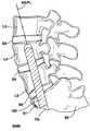
- FIGS. 1-3are lateral, posterior and anterior views of the lumbar and sacral portion of the spinal column depicting the visualized PAIFL and AAIFL extending cephalad and axially from the posterior laminectomy site and the anterior target point, respectively;
- FIG. 4is a sagittal caudal view of lumbar vertebrae depicting a TASIF spinal implant or rod within a TASIF axial bore formed following the visualized PAIFL or AAIFL of FIGS. 1-3;
- FIG. 5is a sagittal caudal view of lumbar vertebrae depicting a plurality, e.g., 2 , TASIF spinal implants or rods within a like plurality of TASIF axial bores formed in parallel with the visualized PAIFL or AAIFL of FIGS. 1-3;
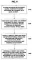
- FIG. 6is a simplified flow chart showing the principal surgical preparation steps of percutaneously accessing a posterior or anterior target point of the sacrum and forming a percutaneous tract following the visualized PAIFL or AAIFL of FIGS. 1-3, as well as subsequent steps of forming the TASIF bore(s) for treatment of accessed vertebral bodies and intervening discs and of implanting spinal implants therein;
- FIG. 7illustrates one exemplary method of step S 100 of FIG. 6 for providing a posterior percutaneous pathway to the posterior target point of the posterior sacrum that the curved PAIFL commences from;
- FIG. 8illustrates one manner of forming the posterior TASIF axial bore through sacral and lumbar vertebrae and intervening discs axially aligned with the visualized PAIFL of FIGS. 1 and 2 in accordance with step S 200 of FIG. 6;
- FIGS. 9 and 10are views of alternate embodiments of a motor driven, canted tip, drill for drilling the posterior or anterior TASIF axial bores following the visualized PAIFL or AAIFL FIGS. 1-5;
- FIG. 11illustrates the location of a curved posterior TASIF spinal implant of any of the types envisaged by the invention inserted into a curved posterior TASIF axial bore following the curvature of the spine and the visualized, curved PAIFL;
- FIGS. 12 and 13illustrate embodiments of posterior and anterior TASIF spinal implants formed of shape memory or superelastic alloy adapted to assume differing curvatures at implantation and body temperatures and insertion tools for inserting the same into posterior and anterior TASIF axial bores;
- FIG. 14illustrates one exemplary method of steps S 100 and S 200 of FIG. 6 for providing an anterior percutaneous tract to the anterior target point of the anterior sacrum aligned with the AAIFL and one manner of forming an anterior TASIF axial bore through sacral and lumbar vertebrae and intervening discs axially aligned with the visualized AAIFL of FIGS. 1 and 2;
- FIG. 15illustrates one manner of performing a discectomy through the TASIF axial bore and anterior tract in accordance with step S 300 of FIG. 6;
- FIG. 16illustrates one manner of performing a disc augmentation through the TASIF axial bore and anterior tract in accordance with step S 300 of FIG. 6;
- FIG. 17illustrates the insertion of a relatively straight anterior TASIF spinal implant of any of the types envisaged by the invention into a relatively straight anterior TASIF axial bore in accordance with step S 400 of FIG. 6;
- FIG. 18illustrates the location of the relatively straight anterior TASIF spinal implant of any of the types envisaged by the invention inserted into a relatively straight anterior TASIF axial bore;
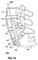
- FIG. 19illustrates the location of a curved anterior TASIF spinal implant of any of the types envisaged by the invention inserted into a curved anterior TASIF axial bore following the curvature of the spine;
- FIG. 20illustrates a further embodiment of a straight anterior or curved posterior or anterior TASIF spinal implant having a plurality of elongated flutes extending along its outer surface through the full length or one or more portion of the length of the spinal implant body and an insertion tool for inserting the same into a curved anterior or posterior TASIF axial bore;
- FIG. 21illustrates a further embodiment of a straight anterior or curved posterior or anterior TASIF spinal implant having a plurality of outwardly extending barbs arranged along its outer surface through the full length or one or more portion of the length of the spinal implant body and an insertion tool for inserting the same into a curved anterior or posterior TASIF axial bore;
- FIG. 22illustrates a further embodiment of a straight anterior or curved posterior or anterior TASIF spinal implant having a plurality of outwardly extending flanges arranged along its outer surface through the full length or one or more portion of the length of the spinal implant body and an insertion tool for inserting the same into a curved anterior or posterior TASIF axial bore;
- FIG. 23illustrates a further embodiment of a straight anterior TASIF is spinal implant having a spiral screw thread around the spinal implant body surface and an insertion tool for inserting the same into a relatively straight anterior TASIF axial bore;
- FIG. 24illustrates a further embodiment of a straight anterior or curved posterior or anterior TASIF spinal implant having a hollow lumen and porous side wall and an insertion tool for inserting the same into a curved anterior or posterior TASIF axial bore;
- FIG. 25illustrates a further embodiment of a straight anterior or curved posterior or anterior TASIF spinal implant having a hollow lumen and a surface roughening treatment in caudal and cephalad portions of the spinal implant body and an insertion tool for inserting the same into a curved anterior or posterior TASIF axial bore.
- Certain of the toolsare selectively employed to form a percutaneous (i.e., through the skin) pathway from an anterior or posterior skin incision to a respective anterior or posterior position, e.g., a target point of a sacral surface or the cephalad end of a pilot hole bored through the sacrum and one or more lumbar vertebrae.
- the percutaneous pathwayis generally axially aligned with an anterior axial instrumentation/fusion line (AAIFL) or a posterior axial instrumentation/fusion line (PAIFL) extending from the respective anterior or posterior target point through at least one sacral vertebral body and one or more lumbar vertebral body in the cephalad direction and visualized by radiographic or fluoroscopic equipment.
- the AAIFL and PAIFLfollow the curvature of the vertebral bodies, although the AAIFL can be straight or relatively straight, depending on the number of vertebrae that the AAIFL is extended through.
- the preferred embodiments of the present inventioninvolye methods and apparatus including surgical tool sets for forming anterior and posterior TASIF axial bores in alignment with the visualized AAIFL and PAIFL and the insertion of spinal implants therein.
- pilot holesmay be bored in the cephalad direction through one or more sacral and lumbar vertebral bodies in alignment with the visualized AAIFL and PAIFL and used as part of the anterior and posterior percutaneous tracts used to form the TASIF axial bores which are also referred to as TASF bores in the above-referenced parent provisional application No. 60/182,748.
- the pilot holes of the anterior and posterior percutaneous tractscan be used to introduce instruments to inspect and/or perform therapies upon the vertebral bodies or intervening discs.
- the posterior or anterior pilot holemay optionally be used as the posterior or anterior TASIF axial bore, respectively, axially aligned with the PAIFL or AAIFL, respectively, to receive spinal implants of various types.
- FIGS. 1-6The following description of FIGS. 1-6 is taken from the above-referenced parent provisional application No. 60/182,748.
- the acronyms TASF, AAFL, and PAFLare changed to TASIF, AAIFL and PAIFL in this application to explicitly acknowledge that instruments can be introduced for inspection or treatments in addition to the fusion and fixation provided by spinal implants that may be inserted into the axial bores or pilot holes.
- FIGS. 1-3schematically illustrate the anterior and posterior TASIF surgical approaches in relation to the lumbar region of the spinal column
- FIGS. 4-5illustrate the location of the TASIF implant or pair of TASIF implants within a corresponding posterior or anterior TASIF axial bore 22 or 152 or pair of TASIF axial bores 22 1 , 22 2 or 152 1 , 152 2
- Preferred TASIF surgical approaches for providing anterior and posterior trans-sacral access depicted in FIGS. 1-3 and preparing the TASIF axial bores 22 or 152 or 22 1 , 22 2 , or 152 1 , 152 2 shown in FIGS. 4 and 5are illustrated in further drawings.
- TASIF pilot hole preparation toolsare depicted in further drawings.
- Two TASIF axial bores and spinal implants or rodsare shown in FIG. 5 to illustrate that a plurality, that is two or more, of the same may be formed and/or employed in side by side relation parallel with the AAIFL or PAIFL.
- FIG. 1The lower regions of the spinal column comprising the coccyx, fused sacral vertebrae S 1 -S 5 forming the sacrum, and the lumbar vertebrae L 1 -L 5 described above are depicted in a lateral view in FIG. 1 .
- the series of adjacent vertebrae located within the human lumbar and sacral spinehave an anterior aspect, a posterior aspect and an axial aspect, and the lumbar vertebrae are separated by intact or damaged spinal discs labeled D-D 5 in FIG. 1 .
- FIGS. 2 and 3depict the posterior and anterior view of the sacrum and coccyx.
- the method and apparatus for inserting one or more spinal implant or rod axially through at least L 4 and L 5 and optionally performing a discectomy of D 5 and/or D 4involves accessing an anterior sacral position, e.g. an anterior target point at the junction of S 1 and S 2 depicted in FIGS. 1 and 3, or a posterior sacral position, e.g. a posterior laminectomy site of S 2 depicted in FIGS. 1 and 2.
- One (or more) visualized, imaginary, axial instrumentation/fusion lineextends cephalad and axially in the axial aspect through the series of adjacent vertebral bodies to be fused, L 4 and L 5 in this illustrated example.
- the visualized AAIFL through L 4 , D 4 , L 5 and D 5extends relatively straight from the anterior target point along S 1 depicted in FIGS. 1 and 3, but may be curved as to follow the curvature of the spinal column in the cephalad direction.
- the visualized PAIFLextends in the cephalad direction with more pronounced curvature from the posterior laminectomy site of S 2 depicted in FIGS. 1 and 2.
- FIG. 6depicts, in general terms, the surgical steps of accessing the anterior or posterior sacral positions illustrated in FIGS. 1-3 (S 100 ) forming posterior and anterior TASIF axial bores (S 200 ), optionally inspecting the discs and vertebral bodies, performing disc removal, disc augmentation, and vertebral bone reinforcement (S 300 ), and implanting posterior and anterior spinal implants and rods (S 400 ) in a simplified manner.
- step S 100access to the anterior or posterior sacral position, that is the anterior target point of FIG. 3 or the posterior laminectomy site of FIG. 2 is obtained, and the anterior or posterior sacral position is penetrated to provide a starting point for each axial bore that is to be created.
- an axial boreis bored from each point of penetration extending along either the PAIFL or AAIFL cephalad and axially through the vertebral bodies of the series of adjacent vertebrae and any intervening spinal discs (S 200 ).
- the axial boremay be visually inspected using an endoscope to determine if the procedures of step S 300 should be performed.
- Discoscopy or discectomy or disc augmentation of an intervening disc or discs or vertebroblasty of a vertebral bodymay be performed through the axial bore (S 300 ).
- an elongated TASIF spinal implant or rodis inserted into each axial bore to extend cephalad and axially through the vertebral bodies of the series of adjacent vertebrae and any intervening spinal discs (S 400 ).
- Other types of spinal implants for delivering therapies or alleviating pain as described abovemay be implanted in substitution for step S 400 .
- step S 100 in the anterior and/or posterior TASIF proceduresmay involye drilling a pilot hole, smaller in diameter than the TASIF axial bore, that tracks the AAIFL and/or PAIFL in order to complete the formation of the anterior and/or posterior percutaneous tracts.
- Step S 300may optionally be completed through the AAIFL/PAIFL pilot hole following step S 100 , rather than following the enlargement of the pilot hole to form the TASIF axial bore in step S 200 .
- Step S 100preferably involves creation an anterior or posterior percutaneous pathway that enables introduction of further tools and instruments for forming an anterior or posterior percutaneous tract extending from the skin incision to the respective anterior or posterior target point of the sacral surface or, in some embodiments, the cephalad end of a pilot hole over which or through which further instruments are introduced as described in the above-referenced 222 application.
- An “anterior, presacral, percutaneous tract”extends through the “presacral space” anterior to the sacrum.
- the posterior percutaneous tract or the anterior, presacral, percutaneous tractis preferably used to bore one or more respective posterior or anterior TASIF bore in the cephalad direction through one or more lumbar vertebral bodies and intervening discs, if present.
- a single anterior or posterior TASIF boreis preferably aligned axially with the respective visualized MIFL or PAIFL, and plural anterior or posterior TASIF bores are preferably aligned in parallel with the respective visualized AAIFL or PAIFL.
- Introduction of spinal implants and instruments for performing discectomies and/or disc and/or vertebral body augmentationis enabled by the provision of the percutaneous pathway and formation of the anterior or posterior TASIF bore(s).
- Step S 100 of FIG. 6 performed in the posterior TASIF procedureinvolves forming a posterior percutaneous tract that preferably extends from a posterior skin incision into the posterior sacrum to a posterior target point exposed by a laminectomy.
- This posterior percutaneous tracthas a tract axis aligned with the visualized PAIFL to provide working space, exposure of the sacrum, and alignment of the boring tool with the visualized PAIFL.
- the posterior percutaneous tractcan take the form of a lumen of a tract sheath introduced through the percutaneous pathway or a guidewire whereby the guidewire provides a percutaneous tract for over the wire passage extending from the skin incision to the posterior target point and aligned with the visualized PAIFL.
- Either or both of the tract sheath or guidewirecan comprise distal fixation mechanisms that enable fixation to the sacral vertebral surface at the posterior target point for through the sheath or over the wire introduction of boring tools or other instruments.
- a pilot hole for each such posterior TASIF boreis optionally bored along or parallel with the visualized PAIFL, and the guidewire distal end is affixed to vertebral bone at the cephalad end of the pilot hole to provide the percutaneous tract for guiding a drill or other instrument to form the posterior TASIF bore or conduct discectomies or disc or vertebral bone augmentation.
- FIG. 7it is expected that the patient 10 , depicted in FIG. 7 in a partial side cross-section view, will lie prone on a surgical table having reverse lordosis support.
- An imaging system(not shown), which may be a CT scanner or bi-plane fluoroscopy machine, is employed first to show the spinal structure and adjacent tissues, vessels and nerves for visualizing the PAIFL through the visible landmarks of the sacrum and lumbar vertebrae. Then, the imaging system is employed during the surgical creation of the posterior TASIF axial bore to ensure that it remains within the vertebral bodies and intervening discs following the PAIFL and does not stray anteriorly, posteriorly or laterally therefrom.
- step S 100depicted in FIG. 7, an incision is made in the patient's skin 12 over the posterior sacral surface of S 2 and a posterior tract 18 is formed through the subcutaneous tissue to expose the posteriorly extending, bony ridge of the posterior sacral surface.
- a small laminectomy 14is performed through the posterior ridge of the sacrum inferior. The thecal sac and nerve roots that are exposed by the laminectomy are gently retracted, and the terminal portion of the spinal canal is exposed.
- a drill guide for receiving a drill bit and shaft for drilling or boring a TASIF axial bore from S 2 along the visualized PAIFL 20may optionally be attached to S 2 and extended posteriorly through the exposed spinal canal and skin incision.
- FIG. 8illustrates the formation of the posterior TASIF axial bore 22 in step S 200 through the centers of two or more vertebral bodies L 4 , L 5 and intervening discs anterior to and extending in parallel with the thecal sac (also shown in FIG. 4, for example).
- the posterior TASIF procedure illustrated in FIG. 8requires a drill capable of drilling or another bore forming mechanism capable of forming the curved TASIF axial bore 22 and a curved TASIF spinal implant or rod 58 capable of being advanced through the curved posterior TASIF axial bore 22 .
- the curved axial boreis made upwardly through S 2 , S 1 and into at least L 5 and optionally extended and curved to follow the curvature of the vertebrae L 4 , L 3 , et seq. in the cephalad direction.
- a curved TASIF implant or rod 58can be inserted into the curved posterior TASIF axial bore 22 to bridge the vertebrae and the intervening discs, if present.
- the optional drill guide 30 having a drill guide sheath lumen 32may be provided and extended through the posterior tract 18 and optionally attached at its distal end to a fixation hole 16 and is aligned axially with the PAIFL 20 .
- a drill bit 44 at the distal end of a directional drill sheath 42 of a drill 40 or 40 ′is carefully advanced using biplane fluoroscopic visualization through the drill guide sheath lumen 32 or directly through the posterior tract 18 if the drill guide sheath 30 is not used.
- the drill drive shaft 46 , 46 ′ within the drill sheath 42is rotated by the drill motor to rotate the drill bit 44 , 44 ′ as it is advanced under fluoroscopic observation along the visualized PAIFL 20 and form the curved posterior TASIF axial bore 22 .
- Suitable exemplary directional drills 40 and 40 ′are schematically depicted in FIGS. 9 and 10.
- the drill 40 of FIG. 9comprises a drill motor housing 50 coupled with drill sheath 42 enclosing the drill drive shaft 46 .
- the drill motor housing 50includes a motor 48 powered by a battery 54 .
- the drill motor 48is coupled to the battery 54 by manipulation of a power switch 52 to rotate the drive shaft 46 and drill bit 44 of drill 40 .
- the drill sheath 42 and drive shaft 46are flexible and can follow the curved posterior TASIF axial bore 22 .
- a pull wire 45extends through a pull wire lumen 49 extending along one side of the sheath 42 between its distal end and a tip curvature control 47 on drill motor housing 50 .
- the distal end portion of drill sheath 42is flexible, and retraction of pull wire 45 by manipulation of tip curvature control 47 causes the distal end portion of drill sheath 42 to assume a curvature from the straight configuration as shown in phantom lines in FIG. 9 .
- the surgeoncan manipulate tip curvature control 47 to control the curvature of the distal end portion of drill sheath 42 and the TASIF axial bore 22 .
- the flexible drill sheath 42 and drive shaft 46can follow the curved posterior TASIF axial bore 22 .
- the drill 40 ′ of FIG. 10comprises a drill motor housing 50 ′ coupled with drill sheath 42 ′ enclosing the drill drive shaft 46 ′.
- the drill motor housing 50 ′includes a battery 54 ′ and motor 48 ′ that is turned on by manipulation of a power switch 52 ′ to rotate the drive shaft 46 ′ and drill bit 44 ′ of drill 40 ′.
- the distal end portion 56 of drill sheath 42 ′is pre-curved or canted at about 20°, for example, providing an eccentric drill bit 44 ′.
- the drill sheath 42 ′ and drive shaft 46 ′are flexible and can follow the curved posterior TASIF axial bore 22 as it is formed.
- the eccentric drill bit 44 ′has an inherent tendency to “veer” in the direction of rotation of the drill bit. Rotating the drill sheath 42 ′ during advancement along the visualized axial fusion line 20 causes it to form the TASIF axial bore 22 that follows the curved PAIFL of FIGS. 1 and 8.
- the flexible drill sheath 42 ′ and drive shaft 46 ′can follow the curved posterior TASIF axial bore 22 .
- the drilling of the posterior TASIF axial bore 22may alternatively be undertaken in sequential steps of first drilling a small diameter pilot hole along the PAIFL 20 using the drill 40 or 40 ′, inserting a guidewire through the pilot hole, and then enlarging the pilot hole to form the curved posterior TASIF axial bore.
- the posterior TASIF axial bore forming tool setmay be similar to the anterior TASIF axial bore forming steps and tools described below.
- a small diameter drill bit and drill shafte.g. 3.0 mm diameter
- the drill bit and shaftare removed, and a guidewire having a threaded distal screw-in tip is advanced through the pilot hole and screwed into to the caudal end of the pilot hole and into cephalad portion of the L 4 body.
- An over-the-wire bore enlarging toolis fitted over the proximal end of the guidewire and manually or mechanically rotated and advanced along it in the manner described below with regard to the formation of the larger diameter, e.g. a 10.0 mm diameter, anterior TASIF axial bore 22 .
- the pilot hole diameteris enlarged to form the anterior TASIF axial bore 22 , and the enlarging tool is then removed.
- the longitudinal, curved, posterior TASIF axial bore 22that is formed in step S 200 of FIG. 6 as described above in reference to FIGS. 7-10 starts in the sacrum at the posterior laminectomy site or target point and extends upwardly or cephalad through the vertebral body of S 1 or S 2 and through the cephalad vertebral bodies including L 5 and L 4 and the intervening discs denoted D 4 and D 5 in FIG. 1 .
- Discs D 4 and D 5are usually damaged or have degenerated between lumbar spine vertebrae and cause the pain experienced by patients requiring intervention and fusion of the vertebrae.
- An inspection of the vertebral bodies and discs along the sides of the TASIF axial bore 22can be made using an elongated endoscope inserted through the TASIF axial bore 22 or the pilot hole if one is formed.
- a discectomy or disc augmentation and/or vertebroblastymay be performed pursuant to step S 300 of FIG. 6 through the posterior TASIF axial bore 22 or pilot hole and laminectomy site to relieve the patient's symptoms and aid in the fusion achieved by the posterior spinal implant or rod 22 .
- the discectomy and disc augmentation proceduresthat can be performed via either the anterior or posterior TASIF axial bore is described further below in reference to FIGS. 15 and 16.
- the posterior TASIF spinal implant or rod that is implanted into the posterior TASIF axial bore 22 formed in step S 200 and depicted in FIG. 8is provided in a number of diameters, lengths and curvatures so that a suitable one may be selected for insertion into a particular TASIF axial bore 22 and may include a variety of fixation mechanisms.
- the curved TASIF spinal implant or rod 58may be formed of autologous bone material or of a bio-compatible material customarily used for bone implants, e.g. titanium, a titanium alloy, e.g., Ti6AI-4Va alloy, or a shape memory or superelastic material, e.g. Nitinol Ni—Ti alloy.
- step S 400 for implanting a curved TASIF spinal implant or rod 58 using an assembly of a spinal implant and a mechanism for implanting or inserting the same in the curved posterior TASIF axial boreis completed as depicted in FIG. 11.
- a preformed curved TASIF spinal implant or rod 58can be formed with a spinal implant or rod body having an axial curvature and diameter that is correlated to the diameter and curvature of the curved, posterior TASIF axial bore 22 to provide for a tight fit.
- the rod bodycan be hollow, having a rod lumen extending between rod body proximal and distal ends enabling advancement of the rod body over a previously placed guidewire extending into the TASIF axial bore 22 , or it can solid and be placed without a guidewire. If present, the rod lumen can be filled with bone fragments retained from drilling posterior TASIF axial bore 22 .
- the curved TASIF spinal implant or rod 58is attached at its threaded proximal end 106 to rod 104 and advanced cephalad into the posterior TASIF axial bore 22 until the distal end of rod 58 is fully seated at the cephalad end of the TASIF axial bore 22 .
- the handle 104is unscrewed from the threads 106 and the remaining insertion tools are withdrawn.
- the proximal end of the posterior TASIF axial bore 22is then preferably plugged with bone fragments retained from drilling the posterior TASIF axial bore 22 and bone cement.
- the laminectomy 14is repaired, and the posterior tract 18 and skin incision are closed.
- a shape memory or superelastic alloyis employed to form the curved TASIF spinal implant or rod 58 as shown in FIG. 12, it may be inserted with a curved shape corresponding to the TASIF axial bore curvature following the PAIFL.
- a curved shape shown in broken linesis assumed or can be imparted in a more malleable state when the curved TASIF spinal implant or rod 58 is cooled below or heated above a shape transition temperature lower or higher than body temperature.
- the curved TASIF spinal implant or rod 58 implanted in the posterior TASIF axial bore 22can be designed to curve or straighten within the posterior TASIF axial bore 22 as it reaches body temperature from cooler room temperature.
- the curved TASIF spinal implant or rod 58is implanted in the posterior TASIF axial bore 22 (using a spinal implant insertion handle 104 in FIGS. 12 and 13 or a pushing tool), it straightens in the direction of arrow 154 or curves even more in the direction of arrow 156 within the posterior TASIF axial bore as it warms or cools to body temperature.
- the body temperature shapeexerts lateral forces against the bore side wall that causes the curved TASIF spinal implant or rod 58 to be retained therein.
- the body temperature curvaturemay also be selected to urge the L 4 and L 5 vertebrae into a more physiologic or therapeutic alignment.
- the curved TASIF spinal implant or rod 58 implanted in the posterior TASIF axial bore 22can be designed to curve even more in the direction of arrow 156 within the posterior TASIF axial bore as it reaches body temperature. In all cases, the curved TASIF spinal implant or rod 58 becomes more rigid at body temperature than when it is at the implantation temperature.
- the curved TASIF spinal implant or rod 58can also be provided with retention mechanisms including surface roughness, hooks, barbs, screw threads, porous side walls, and the like, alone or in combination, to engage the TASIF axial bore 22 along its length and to encourage bone growth that aids in fixation.
- retention mechanismsincluding surface roughness, hooks, barbs, screw threads, porous side walls, and the like, alone or in combination, to engage the TASIF axial bore 22 along its length and to encourage bone growth that aids in fixation.
- retention mechanismsare described further below in reference to FIGS. 20-25.
- bone growth encouraging materialsincluding bone fragments harvested from the patient, hydroxylapatite, or bone morphogenic protein (BMP) or the like can be implanted with the spinal implant 58 .
- a bone cemente.g. polymethylmethacrylate (PMMA) can also be employed to cement the curved TASIF spinal implant or rod 58 into place in the posterior TASIF axial bore 22 along its length.
- PMMA
- the anterior TASIF axial bore spinal implantcan be curved as shown in FIG. 12 to be inserted into a curved anterior TASIF axial bore or can be straighter as shown by the anterior TASIF axial bore spinal implant 102 of FIG. 13 .
- the implantation of a relatively straight anterior TASIF spinal implant 102 in a straight anterior TASIF axial bore 152 of the type depicted in the assembly 100 of FIG. 13is described as follows in relation to exemplary procedure steps S 200 -S 400 of FIG. 6 and the tools depicted in FIGS. 14-18.
- FIG. 19depicts a curved TASIF spinal implant or rod 58 implanted into a curved anterior axial bore 152 ′ tracking a curved AAIFL.
- the anterior percutaneous pathway formed in step S 100is preferably accomplished employing an elongated guide member that is introduced through the skin incision and advanced against the anterior sacrum through the presacral space until the guide member distal end is located at the anterior target point.
- the posterior visceraare pushed aside as the guide member is advanced through presacral space and axially aligned with the AAIFL at the anterior target point of the anterior sacral surface.
- the guide membermay take a variety of forms including a blunt tip rod or a guide assembly of an inner occluder and an outer tubular member fitted together having a tubular member lumen receiving the occluder.
- the occludermay take the form of a solid body member, e.g., an obdurator, a stylet, a guidewire or the like, and the tubular member may take the form of a needle, a trocar, a catheter or the like.
- Either or both of the inner occluder and outer tubular membermay comprise distal fixation mechanisms that enable fixation to the sacral vertebral surface at the anterior target point and/or at the cephalad end of a pilot hole for each such anterior TASIF bore optionally bored along or parallel with the visualized AAIFL.
- the occludercan be employed to blunt the tip of the outer tubular member during introduction to the anterior target point, if the outer tubular member comprises a distal tip fixation mechanism that would otherwise prematurely engage the sacral bone.
- the occludercan have a distal tip fixation mechanism and be retracted within the outer tubular member to prevent its premature attachment to sacral bone during introduction to the anterior target point.
- the anterior, presacral, percutaneous tract formed in step S 100can take the form of the lumen of the outer tubular member upon removal of the occluder or a tube inserted alongside the guide member.
- the anterior percutaneous pathwaycan be expanded to form the anterior, presacral, percutaneous tract through the patient's anterior presacral space having a tract axis aligned with the visualized AAIFL to provide working space and exposure of the sacrum.
- a guidewire having a distal fixation mechanism(which may comprise the occluder) provides the anterior, presacral, percutaneous tract for over-the-wire passage extending from the skin incision to the targe act and aligned with the visualized AAIFL.
- the lumen of a further tract sheath introduced through the percutaneous pathwaye.g., over the guidewire or after removal of the guidewire, provides a percutaneous tract for over the wire passage extending from the skin incision to the target point and aligned with the visualized AAIFL.
- the further tract sheathpreferably has a distal tract sheath fixation mechanism and configuration that enables alignment and attachment to the anterior sacral bone at the anterior target point to maintain the tract sheath lumen aligned axially with a the visualized AAIFL.
- tissue surrounding the skin incision and the anterior, presacral, percutaneous pathway through the presacral spacemay optionally be dilated to form an enlarged diameter presacral, percutaneous tract surrounding a guidewire or tubular member and or to accommodate the insertion of a tract sheath over the guidewire. Dilation can be accomplished manually or by use of one or more dilator or dilatation balloon catheter or any tubular device fitted over a previously extended tubular member or guidewire.
- a pilot holecan be bored in axial alignment or parallel with the visualized AAIFL by a boring tool introduced through the outer tubular member lumen for each such anterior TASIF bore bored along or parallel with the visualized AAIFL.
- the guidewire distal end fixation mechanismis then affixed to vertebral bone at the cephalad end of the pilot hole to provide the percutaneous tract for guiding a drill or other instrument to form the anterior TASIF bore or conduct discectomies or disc or vertebral bone augmentation.
- FIG. 14is an exemplary illustration of certain of the above-described techniques for forming the anterior percutaneous tract 26 and inserting a percutaneous tract sheath 96 and guidewire 80 therethrough.
- One or more relatively straight anterior TASIF axial bore 152 into at least L 5can then be formed in the vertebral column accessed via the anterior, presacral, percutaneous tract to receive a TASIF spinal implant and/or interventional tools inserted through the anterior, presacral, percutaneous tract.
- a curved anterior TASIF axial bore 152 ′ following a visualized, curved, AAIFL extending therethrough as depicted in FIG. 19can be formed to follow the curvature of the vertebrae L 4 , L 3 , et seq. in the cephalad direction using the drill 40 of FIG. 9 or drill 40 ′ of FIG. 10 .
- FIG. 14also depicts further steps of forming a pilot hole 150 and use of the guidewire 80 and a drill bit 140 attached to a drill motor (not shown) to form an anterior TASIF axial bore 152 falling within step S 200 .
- the pilot hole 150is formed using a smaller diameter drill bit (not shown) extended through a further smaller diameter tract sheath attached at its distal end to the anterior sacrum at the anterior target point (not shown).
- a hollow lumen pilot hole drill bitcan be advanced over the guidewire 80 attached at its distal end screw-in tip 82 to the anterior sacrum at the anterior target point and rotated to drill or bore the pilot hole 150 .
- the guidewire 80is attached at its distal end screw-in tip 82 to the cephalad end of the pilot hole 150 , and, optionally, the enlarged diameter tract sheath 96 is placed as shown with its beveled distal end 97 abutting the angled surface of the anterior sacrum.
- the tract sheath 96 and/or guidewire 80are aligned axially with the AAIFL, and the enlarging tool 140 is used to enlarge the pilot hole diameter and form the larger diameter anterior TASIF axial bore 152 .
- the larger diameter enlarging tool 140e.g., a drill bit, ranguer or tap, used in step S 200 and shown in FIG.
- enlarging tool lumen 146extends between the proximal and distal ends of the enlarging tool 140 and enables the enlarging tool 140 to be advanced over the guidewire 80 to position the distal head 142 at the caudal end of the pilot hole 150 .
- a hand operable knob or handlemay be provided at the proximal end of the enlarging tool shaft 144 so that shaft 144 and distal head 142 can be rotated manually to bore or ream or tap out a larger diameter anterior TASIF axial bore 152 as shown in FIG. 20 .
- the enlarging tool shaft proximal endmay be coupled to a drill motor to rotate distal head 142 in the manner of a drill bit.
- the enlarging tool 140is then withdrawn through the anterior TASIF axial bore 152 and the anterior tract 26 over the guidewire 80 .
- the guidewire screw-in tip 82can then be unscrewed from the vertebral bone at the cephalad end of the anterior TASIF axial bore 152 as described above, if it is not needed to perform steps S 300 and S 400 .
- the above-described proceduremay be repeated to form two or more parallel anterior TASIF axial bores 152 .
- the anterior TASIF axial bore(s) 152can be formed in a simpler manner in a single step without first forming a pilot hole 150 or using the above-described guidewire 80 or tract sheathes.
- the longitudinal, anterior TASIF axial bore(s) 152 or 152 ′ that is formed in steps S 100 and S 200 of FIG. 6 as described above in reference to FIG. 14starts in the sacrum at the anterior target point and extends upwardly or cephalad through the vertebral body of S 1 or S 2 and through the cephalad vertebral bodies including L 5 and L 4 and the intervening discs denoted D 4 and D 5 in FIG. 1 .
- Discs D 4 and D 5are usually damaged or have degenerated between lumbar spine vertebrae and cause the pain experienced by patients requiring intervention and fusion of the vertebrae.
- a visual inspection, discectomy and/or disc augmentation and/or vertebroblastymay be performed pursuant to step S 300 of FIG. 6 through the axially aligned anterior TASIF axial bore 152 and anterior tract 26 to relieve the patient's symptoms and aid in the fusion achieved by the spinal implant or rod 152 .
- FIG. 15depicts a insertion of a motor driven discectomy tool 130 through the axially aligned anterior tract 26 and anterior TASIF axial bore 152 or 152 ′ and then laterally into D 4 to mechanically fragment and remove the disc material pursuant to step S 300 of FIG. 6 .
- this illustrated discectomy procedurecan also be practiced through the posterior TASIF bore 22 .
- the illustrated discectomy proceduremay be performed through the pilot hole formed in step S 100 of FIG. 6 and illustrated in FIG. 15 both in the anterior and the posterior TASIF procedure.
- the discectomy tool 130is formed like a flexible atherectomy catheter for fragmenting and removing obstructions in blood vessels using a cutting head 134 to fragment the disc material and aspiration or water flushing to remove the fragments from the disc space.
- the cutting mechanism 134is mounted into a deflectable or steerable distal end section 132 that may be angularly deflected using a pull wire within a pull wire lumen of the elongated, flexible, discectomy tool body 131 and a proximal pull wire control of a proximal guiding and cutting mechanism 134 coupled thereto as described above in reference to deflection mechanism of the drill 40 of FIG. 9 .
- the cutting mechanism 134may comprise any of the known types, e.g., rotating wires, cutting blades, screws, bits, or the like, or using laser energy or ultrasonic energy or water jets or the like.
- the cutting mechanism 134is powered by an energy source within energy source and direction control 136 e.g., a drive motor for rotating a mechanical cutting head, or a source of energy for operating the ultrasonic generator or laser or pressurized fluid.
- the cutting mechanism 134is controlled by a deflection control within energy source and deflection control 136 for operating the pull wire or the like.
- an aspiration lumenis included within the discectomy sheath body 131 with a distal opening adjacent to the cutting head 134 and terminating proximally at a side suction port 138 adapted to be coupled to a source of suction to aspirate the fragments of the disc.
- FIG. 16depicts a disc augmentation tool 160 having a proximal source of augmentation materials 162 coupled to an augmentation tool shaft 164 for delivering augmentation materials to distal exit port 166 in a deflectable distal section 168 of the augmentation tool shaft 164 .
- the augmentation procedureis illustrated in FIG. 22 in the context of employing the anterior TASIF axial bore 152 or pilot hole 150 , but FIG. 16 is intended to convey how the same procedure would be employed using augmentation tool 160 to augment discs accessed via the posterior TASIF axial bore or pilot hole.
- the disc augmentation procedureemploys augmentation materials 170 , e.g., a solid particulate material or a polymer or gel introduced in a fluid form to solidify in situ to provide support between the opposed vertebral bodies.
- augmentation materials 170e.g., a solid particulate material or a polymer or gel introduced in a fluid form to solidify in situ to provide support between the opposed vertebral bodies.
- One or more self-contained inflatable sacmay be delivered into each disc space created in a preceding discectomy or discoscopy and then filled with the disc augmentation materials through the distal exit port 166 .
- the disc augmentation materialscan be pumped or otherwise delivered directly into each disc space through the distal exit port 166 .
- the disc augmentation materialscan be pumped or otherwise delivered directly into the pilot hole 150 of FIG. 14 to fill the disc spaces through it if the disc augmentation procedure employs the pilot hole 150 .
- the excess disc augmentation materialscan be removed form the pilot hole when it is enlarged by the enlarging tool 140 as shown in FIG. 14 .
- pilot hole 150may be drilled in the cephalad direction to access disc D 5 , whereupon a discectomy and disc augmentation procedure may be performed as described above. Then, the pilot hole 150 may be advanced to access disc D 4 , and the discectomy and disc augmentation procedure may be performed as described above.
- the vertebroblasty procedure of step S 300may also be performed via the posterior and anterior pilot holes or TASIF axial bores using an elongated catheter having a deflectable distal end portion and exit port.
- the distal end portioncan be aimed at the side wall of the posterior and anterior pilot holes or TASIF axial bores at selected points and pushed into fractured regions of the vertebral bodies since the vertebral bodies of L 4 and L 5 , for example, are already penetrated by the posterior and anterior pilot holes or TASIF axial bores. It is possible to then pump or otherwise deliver reinforcing materials therein to solidify therein in situ.
- FIG. 17illustrates the performance of step S 400 using the spinal implant assembly 100 ′ of FIG. 13 including an anterior TASIF spinal implant or rod 102 being inserted into the relatively straight anterior TASIF axial bore 152 .
- the anterior spinal implant assembly 100 ′ of FIG. 13comprises the anterior TASIF spinal implant or rod 102 coupled to a spinal implant insertion handle 104 through an attachment and detachment screw thread 106 .
- the anterior TASIF spinal implant or rod 58 and the insertion handle 104can be formed with a rod lumen 103 and handle lumen 105 , respectively, to allow advancement of the spinal implant assembly over the previously placed guidewire 80 as shown in FIG. 17 .
- the spinal assembly 100can be formed without such lumens and can be placed without the guidewire 80 after the guidewire is withdrawn from the anterior TASIF axial bore 152 .
- the spinal implant or rod 102have a surface treatment or retention mechanism of one of the types described below in reference to FIGS. 20-25 and equivalents thereof alone or in combination.
- the anterior TASIF spinal implant or rod 102is advanced cephalad over the guidewire 80 or after the guidewire 80 is withdrawn until its distal end is fully seated at the cephalad end of the anterior TASIF axial bore 152 .
- the handle 104is detached and the remaining insertion tools and the anterior tract sheath 96 are withdrawn.
- the proximal end of the anterior TASIF axial bore 152is plugged with bone fragments retained from drilling the anterior pilot hole 150 and anterior TASIF axial bore 152 and bone cement, and the skin incision 28 are closed.
- FIG. 18depicts the final disposition of a generic form of the relatively straight anterior TASIF spinal implant or rod 102 , including the embodiments described above in reference to FIG. 13 and in the following description of further alternative embodiments.
- a shape memory or superelastic alloyis employed to form the anterior TASIF spinal implant or rod 102 , its initial shape upon insertion is relatively straight as shown in solid lines in FIG. 13 so that it can be inserted in the anterior TASIF axial bore 152 .
- the rod bodycurves in the direction of arrow 154 within the anterior TASIF axial bore 152 and becomes more rigid as it reaches body temperature as shown by the broken line position of FIG. 13 .
- FIG. 19depicts the final disposition of a generic form of the curved anterior TASIF spinal implant or rod 52 , including the embodiments described above and in the following description of further alternative embodiments. If a shape memory or superelastic alloy is employed to form the curved TASIF spinal implant or rod 58 , its initial shape upon insertion is curved as shown in solid lines in FIG. 12 so that it can be inserted into the curved anterior TASIF axial bore 152 ′.
- body temperature shapesexert lateral forces against the TASIF axial bore side wall that causes the curved and anterior spinal implants or rods 58 and 102 to be retained therein.
- the body temperature rod curvaturemay also be selected to impart a physiologic or therapeutic biasing curvature to the vertebrae that they pass through.
- corrective forcescan be applied laterally to maintain a corrected curvature of the spine in the case of above listed types of spinal column disorders.
- the curved TASIF spinal implant or rod 58 or relatively straight anterior TASIF spinal implant or rod 102can also be provided with retention mechanisms including surface roughness, hooks, barbs, screw threads, porous side walls, and the like, alone or in combination, to engage the anterior TASIF axial bore 152 along its length and to encourage bone growth that aids in fixation.
- retention mechanismsincluding surface roughness, hooks, barbs, screw threads, porous side walls, and the like, alone or in combination, to engage the anterior TASIF axial bore 152 along its length and to encourage bone growth that aids in fixation.
- retention mechanismsare described further below in reference to FIGS. 20-26.
- bone growth encouraging materialsincluding bone fragments harvested from the patient, hydroxylapatite, or bone morphogenic protein (BMP) or the like can be implanted with the spinal implant 58 or 102 .
- a bone cemente.g. polymethylmethacrylate (PMMA), can also be employed to cement the curved TASIF spinal implant or rod
- FIGS. 21-26Further embodiments of posterior and anterior spinal implants or rods of the present invention adapted to be fitted into the posterior and anterior TASIF axial bores 22 and 152 , 152 ′ and having specific fixation mechanisms are depicted in FIGS. 21-26. Certain of the illustrated types of posterior and anterior spinal implants of FIGS. 21-26 can be curved or straight. The illustrated fixation mechanisms can be used alone or in combination and can extend the length of the spinal implant body or be restricted to caudal or cephalad portions of the spinal implant body that engage the caudal or cephalad vertebral bodies that the axial bore extends through. Two or more such spinal implants of FIGS. 21-26 can be implanted in the two or more posterior or anterior TASIF axial bores 22 1 , 152 1 / 22 2 , 152 2 of FIG. 5, for example.
- FIG. 20illustrates a further embodiment of a straight anterior or curved posterior or anterior TASIF spinal implant 310 having a plurality of elongated flutes 312 extending along the outer surface of the spinal implant body 314 through the full length or one or more portion of the length of the spinal implant body 314 .
- the implant system 300also includes an insertion tool 320 optionally having a distal end 322 releasably engaging the proximal end opening 316 of the spinal implant body 314 for pushing the same into the anterior or posterior TASIF axial bore.
- the outer diameter of the spinal implant body 314 measured between diametrically opposed flutes 312is greater than the diameter of the axial bore 22 or 152 (or parallel axial bores 22 1 , 152 1 / 22 2 , 152 2 depicted in FIG. 5 ), then the flutes 312 bite into the vertebral bone traversed by the axial bore 22 , 152 .
- the outer diameter measured across the diametrically opposed flutes 312can be equal to or smaller than the diameter of the axial bore 22 or 152 (or parallel axial bores 22 1 , 152 1 / 22 2 , 152 2 depicted in FIG.
- a hollow lumen 318 extending through the spinal implant body 314is depicted, but the spinal implant body 314 can be solid and can include a pointed distal end as in FIG. 22 .
- elongated continuous flutes 312are depicted in this embodiment, it will be understood that they may be interrupted periodically. Moreover, the interruptions can be so closely spaced as to form a knurled outer surface pattern for bone ingrowth.
- FIG. 21illustrates a further embodiment of a straight anterior or curved posterior or anterior TASIF spinal implant 410 having a plurality of barbs 412 distributed along the outer surface of the spinal implant body 414 through the full length or one or more portion of the length of the spinal implant body 414 .
- the implant system 400also includes an insertion tool 420 optionally having a distal end 422 releasably engaging the proximal end opening 416 of the spinal implant body 414 for pushing the same into the anterior or posterior TASIF axial bore.
- the outer diameter of the spinal implant body measured between diametrically opposed barb tips of the barbs 412is greater than the diameter of the axial bore 22 or 152 (or parallel axial bores 22 1 , 152 1 / 22 2 , 152 2 depicted in FIG. 5 ), then the he barbs 412 bite into the vertebral bone traversed by the axial bore 22 , 152 .
- the outer diameter measured across the barb tipscan be equal to or smaller than the diameter of the axial bore 22 or 152 (or parallel axial bores 221 , 152 1 / 22 2 , 152 2 depicted in FIG.
- a hollow lumen 418 extending through the spinal implant body 414is depicted, but the spinal implant body 414 can be solid and can include a pointed distal end.
- FIG. 22illustrates a further embodiment of a straight anterior or curved posterior or anterior TASIF spinal implant 510 having a plurality of flanges 512 distributed along the outer surface of the spinal implant body 514 through the full length or one or more portion of the length of the spinal implant body 514 .
- the implant system 500also includes an insertion tool 520 optionally having a distal end 522 releasably engaging the proximal end opening 516 of the spinal implant body 514 for pushing the same into the anterior or posterior TASIF axial bore.
- the outer diameter of the spinal implant body 514 measured across the flange edgescan be equal to or smaller than the diameter of the axial bore 22 or 152 (or parallel axial bores 22 1 , 152 1 / 22 2 , 152 2 depicted in FIG. 5 ), so that bone cement or bone growth material can be inserted into the bore and distributed about the flanges during the implantation of the TASIF spinal implant 410 into the bore.
- the spinal implant body 514is illustrated as solid and including a pointed distal end 530 , but the spinal implant body can be formed with a hollow lumen extending the length of the spinal implant body 514 .
- FIG. 23illustrates a further embodiment of a TASIF spinal implant 602 having a spiral screw thread 612 around the surface or the spinal implant body 614 and an insertion tool 620 for inserting the same into a relatively straight anterior TASIF axial bore 152 .
- the insertion tool 620has a distal end 622 having a hexagonal wrench configuration, for example, for releasably engaging the proximal end opening 616 of the spinal implant body 614 for rotating the same to advance it into the straight anterior TASIF axial bore.
- the screw thread 612bites into the vertebral bone traversed by the axial bore 152 or bores 152 1 , 152 2 as the or through bone fragments inserted into a bore having a diameter exceeding the diameter of the spinal implant body.
- the spinal implant body 614is illustrated as solid and including a pointed distal end 630 , but the spinal implant body 614 can be formed with a hollow lumen extending the length of the spinal implant body 614 .
- the screw thread 612can be provided on a curved anterior or posterior TASIF spinal implant that has an outer diameter that is smaller than the bore of the respective curved anterior or posterior TASIF axial bore to allow insertion of the curved spinal implant body into the bore. Then, bone growth about the screw thread 612 provides fixation by engagement with the vertebral bone.
- the spinal implant 602is formed of a shape memory material that is superelastic at the implantation temperature, it can be screwed into a curved axial bore.
- the superelastic implant bodycan conform with the curvature of a curved axial bore as the implant body is rotated from its proximal end to enable the screw threads to track a spiral cut into the bore wall of the curved axial bore.
- FIG. 24illustrates a further embodiment of a straight anterior or curved posterior or anterior TASIF spinal implant 702 having a hollow lumen 718 and a porous side wall 728 .
- the implant system 700also includes an insertion tool 720 having a distal end 722 releasably engaging the proximal end opening 716 of the spinal implant body 714 for pushing the same into the anterior or posterior TASIF axial bore.
- the openings or pores 712can be formed as etched or machined or laser drilled through-holes to the lumen 718 in a tubular pipe-like spinal implant body 714 .
- the spinal implant body 714can be formed of a tubular mesh or lattice.
- Materials of the type described above for enabling fixation and/or enhancing bone growthcan be inserted into the lumen 718 and passed through the pores 718 .
- An open distal end to the hollow lumen 718 extending through the spinal implant body 714is depicted, but the distal end of the spinal implant body 714 can be closed and can include a pointed distal end.
- Any of the above-described spinal implantscan be modified to include the hollow lumen 718 and the openings or pores 712 .
- FIG. 25illustrates a further embodiment of a straight anterior or curved posterior or anterior TASIF spinal implant 802 having a hollow lumen 818 and surface roughening treatments 826 and 828 in caudal and cephalad portions of the spinal implant body 814 .
- the implant system 800also includes an insertion tool 820 having a distal end 822 releasably engaging the proximal end opening 816 of the spinal implant body 814 for pushing the same into the anterior or posterior TASIF axial bore.
- the surface roughening treatments 826 and 828can be formed by scribing, sintering particles to, partially through etching, or otherwise roughening the surface to make it more receptive to bone in-growth in situ.
- the roughened surface treatmentcan extend the full length of the surface of the spinal implant body 814 , and any of the above-described spinal implants can be modified to include the roughened surface treatment.
- a spinal implant of one of the above-described typesin the cephalad section of the TASIF axial bore to bridge the space labeled D 4 between vertebrae L 4 and L 5 normally occupied by a disc.
- a second TASIF spinal implantis installed in the caudal section of the same axial bore to bridge the space labeled D 5 between vertebrae L 5 and sacrum S 1 normally occupied by a disc.
- the discs at D 4 and/or D 5may have been removed and/or augmented.
- the caudal ends of the posterior and anterior TASIF boreswould be filled with a material or autologous bone after implantation of any of the above-described spinal implants to close the anterior or posterior sacral surface opening.
- resorbable cement materialis a calcium derivative generally composed of hydroxyapatite, orthophosphoric acid, calcium carbonate, and calcium hydroxide formed into a semi-liquid paste with an alkaline solution of sodium hydroxide and water
- resorbable cement materialis a composition comprising polypropylene fumarate
- compositions further comprising calcium salt filler, N-vinyl-2-pyrrolidone, and a peroxide or free radical initiatorand (4) resorbable cement material comprising a mixture of calcium phosphates.
- Such materials placed in the TASIF axial bores with the TASIF spinal implantscure therein such that fixation occurs between the spinal implants and adjacent vertebral bone of sufficient strength to withstand physiological loads until fixation occurs by osteogenic growth between the bone and the TASIF spinal implants.
Landscapes
- Health & Medical Sciences (AREA)
- Orthopedic Medicine & Surgery (AREA)
- Life Sciences & Earth Sciences (AREA)
- Engineering & Computer Science (AREA)
- Biomedical Technology (AREA)
- Surgery (AREA)
- Animal Behavior & Ethology (AREA)
- Veterinary Medicine (AREA)
- Public Health (AREA)
- Heart & Thoracic Surgery (AREA)
- General Health & Medical Sciences (AREA)
- Oral & Maxillofacial Surgery (AREA)
- Transplantation (AREA)
- Molecular Biology (AREA)
- Medical Informatics (AREA)
- Neurology (AREA)
- Nuclear Medicine, Radiotherapy & Molecular Imaging (AREA)
- Cardiology (AREA)
- Vascular Medicine (AREA)
- Dentistry (AREA)
- Physical Education & Sports Medicine (AREA)
- Chemical & Material Sciences (AREA)
- Dispersion Chemistry (AREA)
- Prostheses (AREA)
- Surgical Instruments (AREA)
- Materials For Medical Uses (AREA)
- Medicines That Contain Protein Lipid Enzymes And Other Medicines (AREA)
Abstract
Description
Claims (17)
Priority Applications (10)
| Application Number | Priority Date | Filing Date | Title |
|---|---|---|---|
| US09/684,820US6558386B1 (en) | 2000-02-16 | 2000-10-10 | Axial spinal implant and method and apparatus for implanting an axial spinal implant within the vertebrae of the spine |
| ES01910614TES2316435T3 (en) | 2000-02-16 | 2001-02-14 | AXIAL SPINAL IMPLANT. |
| AT01910614TATE415132T1 (en) | 2000-02-16 | 2001-02-14 | AXIAL VERTEBRATE IMPLANT |
| AU2001238205AAU2001238205A1 (en) | 2000-02-16 | 2001-02-14 | Axial spinal implant and apparatus for implanting an axial spinal implant within the vertebrae of the spine |
| PCT/US2001/004610WO2001060270A1 (en) | 2000-02-16 | 2001-02-14 | Axial spinal implant and apparatus for implanting an axial spinal implant within the vertebrae of the spine |
| DK01910614TDK1265541T3 (en) | 2000-02-16 | 2001-02-14 | Axial spinal implant |
| DE60136690TDE60136690D1 (en) | 2000-02-16 | 2001-02-14 | Axiales wirbelimplantat |
| JP2001559369AJP4385242B2 (en) | 2000-02-16 | 2001-02-14 | Axial spinal implant and device for implanting an axial spinal implant in the vertebra of the spinal column |
| EP01910614AEP1265541B1 (en) | 2000-02-16 | 2001-02-14 | Axial spinal implant |
| US10/430,751US20030204189A1 (en) | 2000-02-16 | 2003-05-08 | Axial spinal implant and method and apparatus for implanting an axial spinal implant within the vertebrae of the spine |
Applications Claiming Priority (2)
| Application Number | Priority Date | Filing Date | Title |
|---|---|---|---|
| US18274800P | 2000-02-16 | 2000-02-16 | |
| US09/684,820US6558386B1 (en) | 2000-02-16 | 2000-10-10 | Axial spinal implant and method and apparatus for implanting an axial spinal implant within the vertebrae of the spine |
Related Child Applications (1)
| Application Number | Title | Priority Date | Filing Date |
|---|---|---|---|
| US10/430,751ContinuationUS20030204189A1 (en) | 2000-02-16 | 2003-05-08 | Axial spinal implant and method and apparatus for implanting an axial spinal implant within the vertebrae of the spine |
Publications (1)
| Publication Number | Publication Date |
|---|---|
| US6558386B1true US6558386B1 (en) | 2003-05-06 |
Family
ID=26878381
Family Applications (2)
| Application Number | Title | Priority Date | Filing Date |
|---|---|---|---|
| US09/684,820Expired - LifetimeUS6558386B1 (en) | 2000-02-16 | 2000-10-10 | Axial spinal implant and method and apparatus for implanting an axial spinal implant within the vertebrae of the spine |
| US10/430,751AbandonedUS20030204189A1 (en) | 2000-02-16 | 2003-05-08 | Axial spinal implant and method and apparatus for implanting an axial spinal implant within the vertebrae of the spine |
Family Applications After (1)
| Application Number | Title | Priority Date | Filing Date |
|---|---|---|---|
| US10/430,751AbandonedUS20030204189A1 (en) | 2000-02-16 | 2003-05-08 | Axial spinal implant and method and apparatus for implanting an axial spinal implant within the vertebrae of the spine |
Country Status (9)
| Country | Link |
|---|---|
| US (2) | US6558386B1 (en) |
| EP (1) | EP1265541B1 (en) |
| JP (1) | JP4385242B2 (en) |
| AT (1) | ATE415132T1 (en) |
| AU (1) | AU2001238205A1 (en) |
| DE (1) | DE60136690D1 (en) |
| DK (1) | DK1265541T3 (en) |
| ES (1) | ES2316435T3 (en) |
| WO (1) | WO2001060270A1 (en) |
Cited By (189)
| Publication number | Priority date | Publication date | Assignee | Title |
|---|---|---|---|---|
| US20020082600A1 (en)* | 2000-06-23 | 2002-06-27 | Shaolian Samuel M. | Formable orthopedic fixation system |
| US20020198526A1 (en)* | 2000-06-23 | 2002-12-26 | Shaolian Samuel M. | Formed in place fixation system with thermal acceleration |
| US20030083662A1 (en)* | 2001-11-01 | 2003-05-01 | Middleton Lance M. | Orthopaedic implant fixation using an in-situ formed anchor |
| US20030195518A1 (en)* | 2000-02-16 | 2003-10-16 | Cragg Andrew H. | Methods and apparatus for performing therapeutic procedures in the spine |
| US20040002707A1 (en)* | 2002-06-28 | 2004-01-01 | Chunfeng Zhao | Spinal fixation support device and methods of using |
| WO2003105673A3 (en)* | 2002-06-17 | 2004-03-25 | Trimedyne Inc | Devices and methods for minimally invasive treatment of degenerated spinal discs |
| US20040082961A1 (en)* | 2000-06-23 | 2004-04-29 | Teitelbaum George P. | Percutaneous vertebral fusion system |
| US20040092943A1 (en)* | 2002-01-14 | 2004-05-13 | Buttermann Glenn Robin | Apparatus and method for performing spinal surgery |
| US6749614B2 (en) | 2000-06-23 | 2004-06-15 | Vertelink Corporation | Formable orthopedic fixation system with cross linking |
| US20040117409A1 (en)* | 2001-03-03 | 2004-06-17 | Scahill Francis J | Application synchronisation |
| US20040143270A1 (en)* | 2002-10-29 | 2004-07-22 | St. Francis Medical Technologies, Inc. | Tools for implanting artificial vertebral disk and method |
| US20040215190A1 (en)* | 2003-04-25 | 2004-10-28 | Nguyen Thanh V. | System and method for minimally invasive posterior fixation |
| US20040220577A1 (en)* | 2000-02-16 | 2004-11-04 | Cragg Andrew H. | Methods and apparatus for forming shaped axial bores through spinal vertebrae |
| US20040255910A1 (en)* | 2003-01-30 | 2004-12-23 | Klaus Joos | Method, computer program, memory medium, and control and/or regulating device for operating an internal combustion engine, and an internal combustion engine in particular for a motor vehicle |
| US20050004593A1 (en)* | 2001-10-30 | 2005-01-06 | Depuy Spine, Inc. | Non cannulated dilators |
| US20050065517A1 (en)* | 2003-09-24 | 2005-03-24 | Chin Kingsley Richard | Methods and devices for improving percutaneous access in minimally invasive surgeries |
| US20050070908A1 (en)* | 2000-02-16 | 2005-03-31 | Cragg Andrew H. | Articulating spinal implant |
| US20050080418A1 (en)* | 2001-10-30 | 2005-04-14 | Simonson Robert E. | Instruments and methods for minimally invasive spine surgery |
| WO2005039651A2 (en) | 2003-10-23 | 2005-05-06 | Trans1 Inc. | Tools and tool kits for performing minimally invasive procedures on the spine |
| US20050113924A1 (en)* | 2003-08-07 | 2005-05-26 | Dynamic Spine, Inc. | Apparatus and method for performing spinal surgery |
| US20050113928A1 (en)* | 2000-02-16 | 2005-05-26 | Cragg Andrew H. | Dual anchor prosthetic nucleus apparatus |
| US20050113629A1 (en)* | 2003-11-20 | 2005-05-26 | Proxima Therapeutics | Brachytherapy method and applicator for treatment of metastatic lesions in a load bearing region |
| US20050137704A1 (en)* | 2002-04-12 | 2005-06-23 | Steenlage Eric S. | Method and apparatus for reconstructing a ligament |
| US20050149022A1 (en)* | 2000-06-23 | 2005-07-07 | Shaolian Samuel M. | Curable media for implantable medical device |
| US20050165405A1 (en)* | 2001-11-30 | 2005-07-28 | Tsou Paul M. | Minimal access apparatus for endoscopic spinal surgery |
| US20050216002A1 (en)* | 2001-10-30 | 2005-09-29 | Depuy Spine, Inc. | Configured and sized cannula |
| US20050216018A1 (en)* | 2004-03-29 | 2005-09-29 | Sennett Andrew R | Orthopedic surgery access devices |
| US20050244499A1 (en)* | 2004-05-03 | 2005-11-03 | Robert Diaz | Method and device for reducing susceptibility to fractures in long bones |
| US6966929B2 (en) | 2002-10-29 | 2005-11-22 | St. Francis Medical Technologies, Inc. | Artificial vertebral disk replacement implant with a spacer |
| US20050267577A1 (en)* | 2004-05-26 | 2005-12-01 | Trieu Hai H | Methods for treating the spine |
| US20060036241A1 (en)* | 2004-08-11 | 2006-02-16 | Tzony Siegal | Spinal surgery system and method |
| US20060058800A1 (en)* | 2002-12-03 | 2006-03-16 | Trans1 Inc. | Methods and apparatus for provision of therapy to adjacent motion segments |
| WO2006020531A3 (en)* | 2004-08-09 | 2006-04-06 | Trans1 Inc | Prosthetic nucleus apparatus and methods |
| US20060085073A1 (en)* | 2004-10-18 | 2006-04-20 | Kamshad Raiszadeh | Medical device systems for the spine |
| US20060089642A1 (en)* | 2004-10-27 | 2006-04-27 | Diaz Robert L | Prefracture spinal implant for osteoporotic unfractured bone |
| US20060149278A1 (en)* | 2004-11-24 | 2006-07-06 | Abdou Amy M | Devices and methods for inter-vertebral orthopedic device placement |
| US7083649B2 (en) | 2002-10-29 | 2006-08-01 | St. Francis Medical Technologies, Inc. | Artificial vertebral disk replacement implant with translating pivot point |
| US20060184186A1 (en)* | 2005-02-16 | 2006-08-17 | Medtronic Vascular, Inc. | Drilling guidewire for treating chronic total occlusion |
| US20060195094A1 (en)* | 2005-02-15 | 2006-08-31 | Mcgraw J K | Percutaneous spinal stabilization device and method |
| US20060195107A1 (en)* | 2005-02-02 | 2006-08-31 | Jones Bryan S | Ultrasonic cutting device |
| US20060264962A1 (en)* | 2003-09-24 | 2006-11-23 | Chin Kingsley R | System and method for spinal implant placement |
| US20060293750A1 (en)* | 2005-06-03 | 2006-12-28 | Sherman Michael C | Formed in place corpectomy device |
| US20070001981A1 (en)* | 2005-06-29 | 2007-01-04 | Nec Electronics Corporation | Driver unit including common level shifter circuit for display panel and nonvolatile memory |
| US20070010717A1 (en)* | 2000-02-16 | 2007-01-11 | Cragg Andrew H | Methods of performing procedures in the spine |
| US7189235B2 (en) | 1999-10-20 | 2007-03-13 | Anulex Technologies, Inc. | Spinal disc annulus reconstruction method and spinal disc annulus stent |
| US20070093828A1 (en)* | 2005-10-07 | 2007-04-26 | Abdou M S | Devices and methods for inter-vertebral orthopedic device placement |
| US20070106383A1 (en)* | 2005-10-03 | 2007-05-10 | Abdou M S | Devices and methods for inter-vertebral orthopedic device placement |
| US20070112429A1 (en)* | 2004-01-28 | 2007-05-17 | F3 Technologies, Llc | Artificial intervertebral disc |
| US20070162007A1 (en)* | 2004-08-13 | 2007-07-12 | Mazor Surgical Technologies, Ltd. | Minimally invasive spinal fusion |
| US20070213718A1 (en)* | 2006-02-14 | 2007-09-13 | Sdgi Holdings, Inc. | Treatment of the vertebral column |
| US20070213717A1 (en)* | 2006-02-14 | 2007-09-13 | Sdgi Holdings, Inc. | Biological fusion in the vertebral column |
| US20070213823A1 (en)* | 2006-02-14 | 2007-09-13 | Sdgi Holdings, Inc. | Treatment of the vertebral column |
| US7273496B2 (en) | 2002-10-29 | 2007-09-25 | St. Francis Medical Technologies, Inc. | Artificial vertebral disk replacement implant with crossbar spacer and method |
| US20070227547A1 (en)* | 2006-02-14 | 2007-10-04 | Sdgi Holdings, Inc. | Treatment of the vertebral column |
| US7320707B2 (en) | 2003-11-05 | 2008-01-22 | St. Francis Medical Technologies, Inc. | Method of laterally inserting an artificial vertebral disk replacement implant with crossbar spacer |
| US20080027438A1 (en)* | 2006-07-27 | 2008-01-31 | Abdou M S | Devices and methods for the minimally invasive treatment of spinal stenosis |
| US20080051800A1 (en)* | 2004-05-03 | 2008-02-28 | Robert Diaz | Method and device for reducing susceptibility to fractures in vertebral bodies |
| US20080114364A1 (en)* | 2006-11-15 | 2008-05-15 | Aoi Medical, Inc. | Tissue cavitation device and method |
| US20080154367A1 (en)* | 2006-12-21 | 2008-06-26 | Warsaw Orthopedic, Inc. | Methods for positioning a load-bearing component of an orthopedic implant device by inserting a malleable device that hardens in vivo |
| US20080154266A1 (en)* | 2006-12-21 | 2008-06-26 | Warsaw Orthopedic, Inc. | Methods for positioning a load-bearing orthopedic implant device in vivo |
| US20080154373A1 (en)* | 2006-12-21 | 2008-06-26 | Warsaw Orthopedic, Inc. | Curable orthopedic implant devices configured to be hardened after placement in vivo |
| US20080208196A1 (en)* | 2007-02-26 | 2008-08-28 | Team-At-Work, Inc. | Method and device for restoring spinal disc function |
| US7419505B2 (en) | 2003-04-22 | 2008-09-02 | Fleischmann Lewis W | Collapsible, rotatable, and tiltable hydraulic spinal disc prosthesis system with selectable modular components |
| US20080234759A1 (en)* | 2005-04-27 | 2008-09-25 | Trinity Orthopedics, Llc | Mono-Planar Pedicle Screw Method, System and Kit |
| US20080294166A1 (en)* | 2007-05-21 | 2008-11-27 | Mark Goldin | Extendable cutting member |
| US20090005816A1 (en)* | 2007-06-26 | 2009-01-01 | Denardo Andrew J | Spinal rod, insertion device, and method of using |
| US7481840B2 (en) | 2004-09-29 | 2009-01-27 | Kyphon Sarl | Multi-piece artificial spinal disk replacement device with selectably positioning articulating element |
| US7481839B2 (en) | 2003-12-02 | 2009-01-27 | Kyphon Sarl | Bioresorbable interspinous process implant for use with intervertebral disk remediation or replacement implants and procedures |
| US20090030399A1 (en)* | 2007-07-23 | 2009-01-29 | Kamshad Raiszadeh | Drug Delivery Device and Method |
| US20090062916A1 (en)* | 2007-08-27 | 2009-03-05 | Biomedical Enterprises, Inc. | Method and apparatus for an osteotomy fixation or arthrodesis cage |
| US7503935B2 (en) | 2003-12-02 | 2009-03-17 | Kyphon Sarl | Method of laterally inserting an artificial vertebral disk replacement with translating pivot point |
| US20090112267A1 (en)* | 2000-04-04 | 2009-04-30 | Anulex Technologies, Inc. | Devices and methods for the treatment of spinal disorders |
| US20090149890A1 (en)* | 2007-12-05 | 2009-06-11 | Martin Daniel L | Flexible bone screw |
| US7575600B2 (en) | 2004-09-29 | 2009-08-18 | Kyphon Sarl | Artificial vertebral disk replacement implant with translating articulation contact surface and method |
| US7608077B2 (en) | 2000-02-16 | 2009-10-27 | Trans1 Inc. | Method and apparatus for spinal distraction and fusion |
| US7615076B2 (en) | 1999-10-20 | 2009-11-10 | Anulex Technologies, Inc. | Method and apparatus for the treatment of the intervertebral disc annulus |
| US7641657B2 (en) | 2003-06-10 | 2010-01-05 | Trans1, Inc. | Method and apparatus for providing posterior or anterior trans-sacral access to spinal vertebrae |
| US20100016906A1 (en)* | 2008-07-21 | 2010-01-21 | Abdou M Samy | Device and method to access the anterior column of the spine |
| US20100036495A1 (en)* | 2008-08-07 | 2010-02-11 | PX Spine Corporation | Device and method for treating spine |
| US7670377B2 (en) | 2003-11-21 | 2010-03-02 | Kyphon Sarl | Laterally insertable artifical vertebral disk replacement implant with curved spacer |
| US20100069929A1 (en)* | 2004-05-03 | 2010-03-18 | Abdou M S | Devices and methods for the preservation of spinal prosthesis function |
| US20100106250A1 (en)* | 2004-08-23 | 2010-04-29 | Abdou M Samy | Bone fixation and fusion device |
| US7727263B2 (en)* | 2000-02-16 | 2010-06-01 | Trans1, Inc. | Articulating spinal implant |
| US20100161060A1 (en)* | 2008-12-23 | 2010-06-24 | Benvenue Medical, Inc. | Tissue Removal Tools And Methods Of Use |
| US7749251B2 (en) | 2003-06-13 | 2010-07-06 | Aeolin, Llc | Method and apparatus for stabilization of facet joint |
| US20100198262A1 (en)* | 2009-01-30 | 2010-08-05 | Mckinley Laurence M | Axial offset bone fastener system |
| US7771476B2 (en) | 2006-12-21 | 2010-08-10 | Warsaw Orthopedic Inc. | Curable orthopedic implant devices configured to harden after placement in vivo by application of a cure-initiating energy before insertion |
| US20100211177A1 (en)* | 2004-10-05 | 2010-08-19 | Abdou M Samy | Devices and methods for inter-vertebral orthopedic device placement |
| US7799081B2 (en) | 2004-09-14 | 2010-09-21 | Aeolin, Llc | System and method for spinal fusion |
| US7828850B2 (en) | 1999-10-20 | 2010-11-09 | Anulex Technologies, Inc. | Methods and devices for spinal disc annulus reconstruction and repair |
| US20110040329A1 (en)* | 2009-08-14 | 2011-02-17 | Ainsworth Stephen D | Spinal therapy device with fixated distraction distance |
| US20110054535A1 (en)* | 2009-08-28 | 2011-03-03 | Gephart Matthew P | Size Transition Spinal Rod |
| US7909873B2 (en) | 2006-12-15 | 2011-03-22 | Soteira, Inc. | Delivery apparatus and methods for vertebrostenting |
| US20110082424A1 (en)* | 2009-10-02 | 2011-04-07 | Barnhouse Michael P | Method and apparatus for bone graft insertion |
| US7922768B2 (en) | 1999-10-20 | 2011-04-12 | Anulex Technologies, Inc. | Spinal disc annulus reconstruction method and deformable spinal disc annulus stent |
| US7931689B2 (en) | 2000-02-28 | 2011-04-26 | Spineology Inc. | Method and apparatus for treating a vertebral body |
| US7935147B2 (en) | 1999-10-20 | 2011-05-03 | Anulex Technologies, Inc. | Method and apparatus for enhanced delivery of treatment device to the intervertebral disc annulus |
| US7938836B2 (en) | 2003-10-23 | 2011-05-10 | Trans1, Inc. | Driver assembly for simultaneous axial delivery of spinal implants |
| US7951201B2 (en) | 1999-10-20 | 2011-05-31 | Anulex Technologies, Inc. | Method and apparatus for the treatment of the intervertebral disc annulus |
| US20110137349A1 (en)* | 2005-04-12 | 2011-06-09 | Moskowitz Nathan C | Horizontal-transvertebral curvilinear nail-screws with inter-locking rigid or jointed flexible rods for spinal fusion |
| USRE42525E1 (en) | 1999-03-12 | 2011-07-05 | Depuy Spine, Inc. | Cannula and sizing insertion method |
| US8128698B2 (en) | 1999-10-20 | 2012-03-06 | Anulex Technologies, Inc. | Method and apparatus for the treatment of the intervertebral disc annulus |
| US8142462B2 (en) | 2004-05-28 | 2012-03-27 | Cavitech, Llc | Instruments and methods for reducing and stabilizing bone fractures |
| US8163022B2 (en) | 2008-10-14 | 2012-04-24 | Anulex Technologies, Inc. | Method and apparatus for the treatment of the intervertebral disc annulus |
| US8221420B2 (en) | 2009-02-16 | 2012-07-17 | Aoi Medical, Inc. | Trauma nail accumulator |
| US8439947B2 (en) | 2009-07-16 | 2013-05-14 | Howmedica Osteonics Corp. | Suture anchor implantation instrumentation system |
| US8460319B2 (en) | 2010-01-11 | 2013-06-11 | Anulex Technologies, Inc. | Intervertebral disc annulus repair system and method |
| US8556977B2 (en) | 1999-10-20 | 2013-10-15 | Anulex Technologies, Inc. | Tissue anchoring system and method |
| US20140039504A1 (en)* | 2003-10-17 | 2014-02-06 | K2M, Inc. | Systems, Devices and Apparatuses for Bony Fixation and Disk Repair and Replacement and Methods Related Thereto |
| US20140213999A1 (en)* | 2013-01-28 | 2014-07-31 | Olympus Biotech Corporation | Biological Chamber Interbody Spinal Fusion |
| US8795335B1 (en) | 2009-11-06 | 2014-08-05 | Samy Abdou | Spinal fixation devices and methods of use |
| US20140222150A1 (en)* | 2004-08-09 | 2014-08-07 | Mark A. Reiley | Systems and methods for the fixation or fusion of bone |
| US8808294B2 (en) | 2008-09-09 | 2014-08-19 | William Casey Fox | Method and apparatus for a multiple transition temperature implant |
| US8821494B2 (en) | 2012-08-03 | 2014-09-02 | Howmedica Osteonics Corp. | Surgical instruments and methods of use |
| US8906094B2 (en) | 2008-12-31 | 2014-12-09 | Spineology, Inc. | System and method for performing percutaneous spinal interbody fusion |
| US8986348B2 (en) | 2004-08-09 | 2015-03-24 | Si-Bone Inc. | Systems and methods for the fusion of the sacral-iliac joint |
| US9044321B2 (en) | 2012-03-09 | 2015-06-02 | Si-Bone Inc. | Integrated implant |
| US9078740B2 (en) | 2013-01-21 | 2015-07-14 | Howmedica Osteonics Corp. | Instrumentation and method for positioning and securing a graft |
| US9161773B2 (en) | 2008-12-23 | 2015-10-20 | Benvenue Medical, Inc. | Tissue removal tools and methods of use |
| US9192397B2 (en) | 2006-12-15 | 2015-11-24 | Gmedelaware 2 Llc | Devices and methods for fracture reduction |
| US9232954B2 (en) | 2009-08-20 | 2016-01-12 | Howmedica Osteonics Corp. | Flexible ACL instrumentation, kit and method |
| US20160045240A1 (en)* | 2007-09-28 | 2016-02-18 | DePuy Synthes Products, Inc. | Balloon With Shape Control For Spinal Procedures |
| US20160081724A1 (en)* | 2010-10-26 | 2016-03-24 | Christian Röbling | Process for introducing a stabilizing element into a vertebral element |
| US9375323B2 (en) | 2004-08-09 | 2016-06-28 | Si-Bone Inc. | Apparatus, systems, and methods for achieving trans-iliac lumbar fusion |
| US9402620B2 (en) | 2013-03-04 | 2016-08-02 | Howmedica Osteonics Corp. | Knotless filamentary fixation devices, assemblies and systems and methods of assembly and use |
| US9408716B1 (en) | 2013-12-06 | 2016-08-09 | Stryker European Holdings I, Llc | Percutaneous posterior spinal fusion implant construction and method |
| US9463013B2 (en) | 2013-03-13 | 2016-10-11 | Stryker Corporation | Adjustable continuous filament structure and method of manufacture and use |
| FR3034977A1 (en)* | 2015-04-16 | 2016-10-21 | Clariance | PERCUTANEOUS TRANSPEDICULAR FUSION DEVICE |
| US9480485B2 (en) | 2006-12-15 | 2016-11-01 | Globus Medical, Inc. | Devices and methods for vertebrostenting |
| US9492201B2 (en) | 2004-08-09 | 2016-11-15 | Si-Bone Inc. | Apparatus, systems and methods for achieving anterior lumbar interbody fusion |
| WO2016181078A1 (en)* | 2015-05-11 | 2016-11-17 | Fischer Lokou David François | Implant for the fixation of bone elements |
| US9510875B2 (en) | 2013-03-14 | 2016-12-06 | Stryker European Holdings I, Llc | Systems and methods for percutaneous spinal fusion |
| US20170065290A1 (en)* | 2015-09-04 | 2017-03-09 | Jeffrey Scott Smith | Posterior to Lateral Interbody Fusion Approach with Associated Instrumentation and Implants |
| US9622783B2 (en) | 2004-08-09 | 2017-04-18 | Si-Bone Inc. | Systems and methods for the fixation or fusion of bone |
| US9662158B2 (en) | 2004-08-09 | 2017-05-30 | Si-Bone Inc. | Systems and methods for the fixation or fusion of bone at or near a sacroiliac joint |
| US9662157B2 (en) | 2014-09-18 | 2017-05-30 | Si-Bone Inc. | Matrix implant |
| US9737294B2 (en) | 2013-01-28 | 2017-08-22 | Cartiva, Inc. | Method and system for orthopedic repair |
| US9744050B1 (en) | 2013-12-06 | 2017-08-29 | Stryker European Holdings I, Llc | Compression and distraction system for percutaneous posterior spinal fusion |
| US9788826B2 (en) | 2013-03-11 | 2017-10-17 | Howmedica Osteonics Corp. | Filamentary fixation device and assembly and method of assembly, manufacture and use |
| US9795398B2 (en) | 2011-04-13 | 2017-10-24 | Howmedica Osteonics Corp. | Flexible ACL instrumentation, kit and method |
| US9814598B2 (en) | 2013-03-14 | 2017-11-14 | Quandary Medical, Llc | Spinal implants and implantation system |
| US9827020B2 (en) | 2013-03-14 | 2017-11-28 | Stryker European Holdings I, Llc | Percutaneous spinal cross link system and method |
| US9839448B2 (en) | 2013-10-15 | 2017-12-12 | Si-Bone Inc. | Implant placement |
| WO2018019962A1 (en)* | 2016-07-29 | 2018-02-01 | Spine Arch Brevet | Helicoidal implant for the fixation of bone elements |
| US9936983B2 (en) | 2013-03-15 | 2018-04-10 | Si-Bone Inc. | Implants for spinal fixation or fusion |
| US9949843B2 (en) | 2004-08-09 | 2018-04-24 | Si-Bone Inc. | Apparatus, systems, and methods for the fixation or fusion of bone |
| US9986992B2 (en) | 2014-10-28 | 2018-06-05 | Stryker Corporation | Suture anchor and associated methods of use |
| US10034768B2 (en)* | 2015-09-02 | 2018-07-31 | Globus Medical, Inc. | Implantable systems, devices and related methods |
| US20180271575A1 (en)* | 2014-08-20 | 2018-09-27 | ZynFusion, LLC | Minimally invasive spinal fusion system and method |
| US10159579B1 (en) | 2013-12-06 | 2018-12-25 | Stryker European Holdings I, Llc | Tubular instruments for percutaneous posterior spinal fusion systems and methods |
| US10166033B2 (en) | 2014-09-18 | 2019-01-01 | Si-Bone Inc. | Implants for bone fixation or fusion |
| US10179012B2 (en) | 2013-01-28 | 2019-01-15 | Cartiva, Inc. | Systems and methods for orthopedic repair |
| US10314605B2 (en) | 2014-07-08 | 2019-06-11 | Benvenue Medical, Inc. | Apparatus and methods for disrupting intervertebral disc tissue |
| US10363140B2 (en) | 2012-03-09 | 2019-07-30 | Si-Bone Inc. | Systems, device, and methods for joint fusion |
| US10376206B2 (en) | 2015-04-01 | 2019-08-13 | Si-Bone Inc. | Neuromonitoring systems and methods for bone fixation or fusion procedures |
| US10426533B2 (en) | 2012-05-04 | 2019-10-01 | Si-Bone Inc. | Fenestrated implant |
| US10448944B2 (en) | 2011-11-23 | 2019-10-22 | Howmedica Osteonics Corp. | Filamentary fixation device |
| US10543107B2 (en) | 2009-12-07 | 2020-01-28 | Samy Abdou | Devices and methods for minimally invasive spinal stabilization and instrumentation |
| US10548740B1 (en) | 2016-10-25 | 2020-02-04 | Samy Abdou | Devices and methods for vertebral bone realignment |
| US10568616B2 (en) | 2014-12-17 | 2020-02-25 | Howmedica Osteonics Corp. | Instruments and methods of soft tissue fixation |
| US10575961B1 (en) | 2011-09-23 | 2020-03-03 | Samy Abdou | Spinal fixation devices and methods of use |
| US10610211B2 (en) | 2013-12-12 | 2020-04-07 | Howmedica Osteonics Corp. | Filament engagement system and methods of use |
| US10695105B2 (en) | 2012-08-28 | 2020-06-30 | Samy Abdou | Spinal fixation devices and methods of use |
| USD902405S1 (en) | 2018-02-22 | 2020-11-17 | Stryker Corporation | Self-punching bone anchor inserter |
| US10857003B1 (en) | 2015-10-14 | 2020-12-08 | Samy Abdou | Devices and methods for vertebral stabilization |
| US10888432B2 (en) | 2017-07-27 | 2021-01-12 | Quandary Medical Llc | Lordotic rod-washer implant for lumbo-sacral fusion |
| US10973648B1 (en) | 2016-10-25 | 2021-04-13 | Samy Abdou | Devices and methods for vertebral bone realignment |
| US11006982B2 (en) | 2012-02-22 | 2021-05-18 | Samy Abdou | Spinous process fixation devices and methods of use |
| US11116519B2 (en) | 2017-09-26 | 2021-09-14 | Si-Bone Inc. | Systems and methods for decorticating the sacroiliac joint |
| US11147688B2 (en) | 2013-10-15 | 2021-10-19 | Si-Bone Inc. | Implant placement |
| US11173040B2 (en) | 2012-10-22 | 2021-11-16 | Cogent Spine, LLC | Devices and methods for spinal stabilization and instrumentation |
| US11179248B2 (en) | 2018-10-02 | 2021-11-23 | Samy Abdou | Devices and methods for spinal implantation |
| US11234830B2 (en) | 2019-02-14 | 2022-02-01 | Si-Bone Inc. | Implants for spinal fixation and or fusion |
| US11331094B2 (en) | 2013-04-22 | 2022-05-17 | Stryker Corporation | Method and apparatus for attaching tissue to bone |
| US11369419B2 (en) | 2019-02-14 | 2022-06-28 | Si-Bone Inc. | Implants for spinal fixation and or fusion |
| CN115153827A (en)* | 2022-08-03 | 2022-10-11 | 武汉零壹医疗科技有限公司 | Laser gun device for biological bone tissue drilling curved hole |
| US11471145B2 (en) | 2018-03-16 | 2022-10-18 | Spinal Elements, Inc. | Articulated instrumentation and methods of using the same |
| US11564811B2 (en) | 2015-02-06 | 2023-01-31 | Spinal Elements, Inc. | Graft material injector system and method |
| US11571245B2 (en) | 2019-11-27 | 2023-02-07 | Si-Bone Inc. | Bone stabilizing implants and methods of placement across SI joints |
| US11583327B2 (en) | 2018-01-29 | 2023-02-21 | Spinal Elements, Inc. | Minimally invasive interbody fusion |
| US11602368B2 (en) | 2015-09-04 | 2023-03-14 | Jeffrey Scott Smith | Posterior to lateral interbody fusion approach with associated instrumentation and implants |
| US11633292B2 (en) | 2005-05-24 | 2023-04-25 | Si-Bone Inc. | Apparatus, systems, and methods for the fixation or fusion of bone |
| US11752011B2 (en) | 2020-12-09 | 2023-09-12 | Si-Bone Inc. | Sacro-iliac joint stabilizing implants and methods of implantation |
| US11771483B2 (en) | 2017-03-22 | 2023-10-03 | Spinal Elements, Inc. | Minimal impact access system to disc space |
| USRE49994E1 (en) | 2013-03-14 | 2024-06-04 | Spinal Elements, Inc. | Spinal fusion implants and devices and methods for deploying such implants |
| US12083026B2 (en) | 2019-12-09 | 2024-09-10 | Si-Bone Inc. | Sacro-iliac joint stabilizing implants and methods of implantation |
| US12419668B2 (en) | 2019-11-21 | 2025-09-23 | Si-Bone Inc. | Rod coupling assemblies for bone stabilization constructs |
| US12427028B2 (en) | 2018-03-28 | 2025-09-30 | Si-Bone Inc. | Threaded implants and methods of use across bone segments |
| US12433733B2 (en) | 2023-08-15 | 2025-10-07 | Si-Bone Inc. | Pelvic stabilization implants, methods of use and manufacture |
Families Citing this family (58)
| Publication number | Priority date | Publication date | Assignee | Title |
|---|---|---|---|---|
| EP0873145A2 (en) | 1996-11-15 | 1998-10-28 | Advanced Bio Surfaces, Inc. | Biomaterial system for in situ tissue repair |
| US7621950B1 (en) | 1999-01-27 | 2009-11-24 | Kyphon Sarl | Expandable intervertebral spacer |
| US6293949B1 (en)* | 2000-03-01 | 2001-09-25 | Sdgi Holdings, Inc. | Superelastic spinal stabilization system and method |
| ES2545328T3 (en) | 2003-03-14 | 2015-09-10 | Depuy Spine, Inc. | Bone cement hydraulic injection device in percutaneous vertebroplasty |
| TWI315010B (en)* | 2003-03-31 | 2009-09-21 | Sharp Corporatio | Liquid crystal display device and method of manufacturing the same |
| US8066713B2 (en) | 2003-03-31 | 2011-11-29 | Depuy Spine, Inc. | Remotely-activated vertebroplasty injection device |
| US8415407B2 (en) | 2004-03-21 | 2013-04-09 | Depuy Spine, Inc. | Methods, materials, and apparatus for treating bone and other tissue |
| US8579908B2 (en) | 2003-09-26 | 2013-11-12 | DePuy Synthes Products, LLC. | Device for delivering viscous material |
| US7799053B2 (en)* | 2004-03-08 | 2010-09-21 | Warsaw Orthopedic, Inc. | Occipital and cervical stabilization systems and methods |
| US7637927B2 (en)* | 2004-03-25 | 2009-12-29 | Hyde Jr Edward R | Transosseous spine core approach method implant and instrumentation |
| JP2008503275A (en)* | 2004-06-16 | 2008-02-07 | ウォーソー・オーソペディック・インコーポレーテッド | Surgical instruments and methods for treatment of spinal structures |
| CN101065080B (en) | 2004-07-30 | 2021-10-29 | 德普伊新特斯产品有限责任公司 | Materials and Instruments for Manipulating Bone and Other Tissues |
| WO2006034436A2 (en) | 2004-09-21 | 2006-03-30 | Stout Medical Group, L.P. | Expandable support device and method of use |
| WO2006090379A2 (en)* | 2005-02-22 | 2006-08-31 | Disc-O-Tech Medical Technologies, Ltd. | Methods, materials and apparatus for treating bone and other tissue |
| US20060235386A1 (en)* | 2005-04-14 | 2006-10-19 | Sdgi Holdings, Inc. | Magnetic manipulation of a cable in blind approach |
| EP1903949A2 (en) | 2005-07-14 | 2008-04-02 | Stout Medical Group, L.P. | Expandable support device and method of use |
| US9381024B2 (en) | 2005-07-31 | 2016-07-05 | DePuy Synthes Products, Inc. | Marked tools |
| US9918767B2 (en) | 2005-08-01 | 2018-03-20 | DePuy Synthes Products, Inc. | Temperature control system |
| US7611537B2 (en)* | 2005-08-01 | 2009-11-03 | Warsaw Orthopedic, Inc. | System, device, and method for percutaneous interbody device and nucleus removal system |
| US20090112321A1 (en)* | 2005-08-04 | 2009-04-30 | Kitchen Michael S | Spinal stabilization device and method |
| US20100070043A1 (en)* | 2005-08-04 | 2010-03-18 | Kitchen Michael S | Shape memory orthopedic joint |
| US8360629B2 (en) | 2005-11-22 | 2013-01-29 | Depuy Spine, Inc. | Mixing apparatus having central and planetary mixing elements |
| EP1981422B1 (en) | 2006-02-06 | 2018-10-24 | Stryker European Holdings I, LLC | Rod contouring apparatus for percutaneous pedicle screw extension |
| EP2023864B1 (en) | 2006-05-01 | 2019-07-10 | Stout Medical Group, L.P. | Expandable support device |
| US8109957B2 (en) | 2006-06-30 | 2012-02-07 | Depuy Spine, Inc. | Disc nucleus removal devices and methods |
| US8298264B2 (en)* | 2006-09-07 | 2012-10-30 | Warsaw Orthopedic, Inc | Systems and methods for use in spinal support |
| AU2007297097A1 (en) | 2006-09-14 | 2008-03-20 | Depuy Spine, Inc. | Bone cement and methods of use thereof |
| US8950929B2 (en) | 2006-10-19 | 2015-02-10 | DePuy Synthes Products, LLC | Fluid delivery system |
| US7931651B2 (en)* | 2006-11-17 | 2011-04-26 | Wake Lake University Health Sciences | External fixation assembly and method of use |
| US8974496B2 (en) | 2007-08-30 | 2015-03-10 | Jeffrey Chun Wang | Interspinous implant, tools and methods of implanting |
| US20080255615A1 (en)* | 2007-03-27 | 2008-10-16 | Warsaw Orthopedic, Inc. | Treatments for Correcting Spinal Deformities |
| WO2009051779A1 (en)* | 2007-10-17 | 2009-04-23 | Kitchen Michael S | Spinal stabilization device and method |
| US20090198243A1 (en)* | 2008-02-06 | 2009-08-06 | Melsheimer Jeffry S | Device and method for stabilizing a damaged bone with a bone cement mixture |
| US8202299B2 (en) | 2008-03-19 | 2012-06-19 | Collabcom II, LLC | Interspinous implant, tools and methods of implanting |
| WO2009131955A1 (en)* | 2008-04-21 | 2009-10-29 | Total Connect Spine, Llc | Posterior spinal fastener and method for using same |
| EP2285312A4 (en) | 2008-05-01 | 2014-03-12 | Columna Pty Ltd | Systems methods and apparatuses for formation and insertion of tissue prostheses |
| US9357985B2 (en)* | 2008-05-15 | 2016-06-07 | Spinal Elements, Inc. | Method for accessing a spinal facet joint |
| EP2278931A1 (en)* | 2008-05-30 | 2011-02-02 | Synthes GmbH | Balloon-assisted annulus repair |
| US8951289B2 (en) | 2008-10-09 | 2015-02-10 | Total Connect Spine, Llc | Spinal connection assembly |
| WO2010056895A1 (en) | 2008-11-12 | 2010-05-20 | Stout Medical Group, L.P. | Fixation device and method |
| US20100211176A1 (en) | 2008-11-12 | 2010-08-19 | Stout Medical Group, L.P. | Fixation device and method |
| EP2459082A4 (en)* | 2009-07-30 | 2015-07-08 | Smith & Nephew Inc | Instrument for creating microfractures in a bone |
| EP2467099B1 (en) | 2009-08-19 | 2019-05-15 | Synthes GmbH | Apparatus for augmenting bone |
| US20110264098A1 (en)* | 2010-02-26 | 2011-10-27 | Cobbs Charles S | Minimally invasive systems, devices, and surgical methods for performing arthrodesis in the spine |
| EP2608747A4 (en) | 2010-08-24 | 2015-02-11 | Flexmedex Llc | Support device and method for use |
| WO2013079753A1 (en)* | 2011-12-01 | 2013-06-06 | Alonso Abajo Antonio-Magin | Device for the treatment of vertebral column disorders |
| FR3010628B1 (en) | 2013-09-18 | 2015-10-16 | Medicrea International | METHOD FOR REALIZING THE IDEAL CURVATURE OF A ROD OF A VERTEBRAL OSTEOSYNTHESIS EQUIPMENT FOR STRENGTHENING THE VERTEBRAL COLUMN OF A PATIENT |
| FR3012030B1 (en) | 2013-10-18 | 2015-12-25 | Medicrea International | METHOD FOR REALIZING THE IDEAL CURVATURE OF A ROD OF A VERTEBRAL OSTEOSYNTHESIS EQUIPMENT FOR STRENGTHENING THE VERTEBRAL COLUMN OF A PATIENT |
| CA3008161C (en) | 2014-12-09 | 2023-09-26 | John A. Heflin | Spine alignment system |
| WO2018109556A1 (en) | 2016-12-12 | 2018-06-21 | Medicrea International | Systems and methods for patient-specific spinal implants |
| EP3612122B1 (en) | 2017-04-21 | 2023-12-20 | Medicrea International | A system for developing one or more patient-specific spinal implants |
| US10918422B2 (en) | 2017-12-01 | 2021-02-16 | Medicrea International | Method and apparatus for inhibiting proximal junctional failure |
| US11712272B2 (en)* | 2018-12-18 | 2023-08-01 | Frank J. Schwab | Technologies for lines coupled to spines |
| US11925417B2 (en) | 2019-04-02 | 2024-03-12 | Medicrea International | Systems, methods, and devices for developing patient-specific spinal implants, treatments, operations, and/or procedures |
| US11877801B2 (en) | 2019-04-02 | 2024-01-23 | Medicrea International | Systems, methods, and devices for developing patient-specific spinal implants, treatments, operations, and/or procedures |
| US11944385B2 (en) | 2019-04-02 | 2024-04-02 | Medicrea International | Systems and methods for medical image analysis |
| US11769251B2 (en) | 2019-12-26 | 2023-09-26 | Medicrea International | Systems and methods for medical image analysis |
| US12318144B2 (en) | 2021-06-23 | 2025-06-03 | Medicrea International SA | Systems and methods for planning a patient-specific spinal correction |
Citations (116)
| Publication number | Priority date | Publication date | Assignee | Title |
|---|---|---|---|---|
| US1630239A (en) | 1924-05-09 | 1927-05-24 | Roy S Binkley | Antrum burr |
| US3367326A (en) | 1965-06-15 | 1968-02-06 | Calvin H. Frazier | Intra spinal fixation rod |
| US3554192A (en) | 1967-07-24 | 1971-01-12 | Orthopedic Equipment Co | Medullary space drill |
| US3892232A (en) | 1973-09-24 | 1975-07-01 | Alonzo J Neufeld | Method and apparatus for performing percutaneous bone surgery |
| US4135506A (en) | 1976-03-16 | 1979-01-23 | Ulrich Max B | Method of and device for pinning a fractured vertebra |
| US4170990A (en) | 1977-01-28 | 1979-10-16 | Fried. Krupp Gesellschaft Mit Beschrankter Haftung | Method for implanting and subsequently removing mechanical connecting elements from living tissue |
| US4265231A (en) | 1979-04-30 | 1981-05-05 | Scheller Jr Arnold D | Curved drill attachment for bone drilling uses |
| US4401112A (en) | 1980-09-15 | 1983-08-30 | Rezaian Seyed M | Spinal fixator |
| US4453539A (en) | 1982-03-01 | 1984-06-12 | The University Of Toledo | Expandable intramedullary nail for the fixation of bone fractures |
| US4541423A (en) | 1983-01-17 | 1985-09-17 | Barber Forest C | Drilling a curved hole |
| US4553273A (en) | 1983-11-23 | 1985-11-19 | Henry Ford Hospital | Vertebral body prosthesis and spine stabilizing method |
| US4554914A (en) | 1983-10-04 | 1985-11-26 | Kapp John P | Prosthetic vertebral body |
| US4573448A (en) | 1983-10-05 | 1986-03-04 | Pilling Co. | Method for decompressing herniated intervertebral discs |
| US4636217A (en) | 1985-04-23 | 1987-01-13 | Regents Of The University Of Minnesota | Anterior spinal implant |
| US4756649A (en) | 1986-01-29 | 1988-07-12 | Heinrich Heule | Counterbore for the bilateral attachment of plane surfaces to bolt holes |
| US4844088A (en) | 1987-12-11 | 1989-07-04 | Parviz Kambin | Surgical cutting device with reciprocating cutting member |
| US4862891A (en) | 1988-03-14 | 1989-09-05 | Canyon Medical Products | Device for sequential percutaneous dilation |
| USRE33258E (en) | 1984-07-23 | 1990-07-10 | Surgical Dynamics Inc. | Irrigating, cutting and aspirating system for percutaneous surgery |
| US4966604A (en) | 1989-01-23 | 1990-10-30 | Interventional Technologies Inc. | Expandable atherectomy cutter with flexibly bowed blades |
| US4969888A (en) | 1989-02-09 | 1990-11-13 | Arie Scholten | Surgical protocol for fixation of osteoporotic bone using inflatable device |
| US5002546A (en) | 1987-04-13 | 1991-03-26 | Romano Jack W | Curved bore drilling apparatus |
| US5015255A (en) | 1989-05-10 | 1991-05-14 | Spine-Tech, Inc. | Spinal stabilization method |
| US5030201A (en) | 1989-11-24 | 1991-07-09 | Aubrey Palestrant | Expandable atherectomy catheter device |
| US5059193A (en) | 1989-11-20 | 1991-10-22 | Spine-Tech, Inc. | Expandable spinal implant and surgical method |
| US5062850A (en) | 1990-01-16 | 1991-11-05 | University Of Florida | Axially-fixed vertebral body prosthesis and method of fixation |
| US5071437A (en) | 1989-02-15 | 1991-12-10 | Acromed Corporation | Artificial disc |
| US5171279A (en) | 1992-03-17 | 1992-12-15 | Danek Medical | Method for subcutaneous suprafascial pedicular internal fixation |
| US5190546A (en) | 1983-10-14 | 1993-03-02 | Raychem Corporation | Medical devices incorporating SIM alloy elements |
| US5192326A (en) | 1990-12-21 | 1993-03-09 | Pfizer Hospital Products Group, Inc. | Hydrogel bead intervertebral disc nucleus |
| US5195968A (en) | 1990-02-02 | 1993-03-23 | Ingemar Lundquist | Catheter steering mechanism |
| US5242443A (en) | 1991-08-15 | 1993-09-07 | Smith & Nephew Dyonics, Inc. | Percutaneous fixation of vertebrae |
| US5242461A (en) | 1991-07-22 | 1993-09-07 | Dow Corning Wright | Variable diameter rotating recanalization catheter and surgical method |
| US5242444A (en) | 1991-11-04 | 1993-09-07 | University Of Florida | Lumbosacral fixation and fusion method and device |
| US5258031A (en) | 1992-01-06 | 1993-11-02 | Danek Medical | Intervertebral disk arthroplasty |
| US5269785A (en) | 1990-06-28 | 1993-12-14 | Bonutti Peter M | Apparatus and method for tissue removal |
| US5285795A (en) | 1991-09-12 | 1994-02-15 | Surgical Dynamics, Inc. | Percutaneous discectomy system having a bendable discectomy probe and a steerable cannula |
| US5290289A (en) | 1990-05-22 | 1994-03-01 | Sanders Albert E | Nitinol spinal instrumentation and method for surgically treating scoliosis |
| US5313962A (en) | 1991-10-18 | 1994-05-24 | Obenchain Theodore G | Method of performing laparoscopic lumbar discectomy |
| US5336223A (en) | 1993-02-04 | 1994-08-09 | Rogers Charles L | Telescoping spinal fixator |
| US5366457A (en) | 1991-12-13 | 1994-11-22 | David A. McGuire | Method and apparatus for preparing a bone and tendon graft |
| US5383884A (en) | 1992-12-04 | 1995-01-24 | American Biomed, Inc. | Spinal disc surgical instrument |
| US5395188A (en) | 1993-12-23 | 1995-03-07 | Roy E. Bowling | Guide for angled and curved drilling |
| US5395317A (en) | 1991-10-30 | 1995-03-07 | Smith & Nephew Dyonics, Inc. | Unilateral biportal percutaneous surgical procedure |
| US5396880A (en) | 1992-04-08 | 1995-03-14 | Danek Medical, Inc. | Endoscope for direct visualization of the spine and epidural space |
| US5403276A (en) | 1993-02-16 | 1995-04-04 | Danek Medical, Inc. | Apparatus for minimally invasive tissue removal |
| US5415661A (en) | 1993-03-24 | 1995-05-16 | University Of Miami | Implantable spinal assist device |
| US5433739A (en) | 1993-11-02 | 1995-07-18 | Sluijter; Menno E. | Method and apparatus for heating an intervertebral disc for relief of back pain |
| US5480440A (en) | 1991-08-15 | 1996-01-02 | Smith & Nephew Richards, Inc. | Open surgical technique for vertebral fixation with subcutaneous fixators positioned between the skin and the lumbar fascia of a patient |
| US5505732A (en) | 1988-06-13 | 1996-04-09 | Michelson; Gary K. | Apparatus and method of inserting spinal implants |
| US5514180A (en) | 1994-01-14 | 1996-05-07 | Heggeness; Michael H. | Prosthetic intervertebral devices |
| US5514137A (en) | 1993-12-06 | 1996-05-07 | Coutts; Richard D. | Fixation of orthopedic devices |
| EP0611116B1 (en) | 1993-02-11 | 1996-07-17 | SMITH & NEPHEW RICHARDS, INC. | Spinal column retaining apparatus |
| US5549679A (en) | 1994-05-20 | 1996-08-27 | Kuslich; Stephen D. | Expandable fabric implant for stabilizing the spinal motion segment |
| US5554163A (en) | 1995-04-27 | 1996-09-10 | Shturman Cardiology Systems, Inc. | Atherectomy device |
| US5558674A (en) | 1993-12-17 | 1996-09-24 | Smith & Nephew Richards, Inc. | Devices and methods for posterior spinal fixation |
| US5562736A (en) | 1994-10-17 | 1996-10-08 | Raymedica, Inc. | Method for surgical implantation of a prosthetic spinal disc nucleus |
| US5571190A (en) | 1993-08-20 | 1996-11-05 | Heinrich Ulrich | Implant for the replacement of vertebrae and/or stabilization and fixing of the spinal column |
| US5584887A (en) | 1991-08-15 | 1996-12-17 | Smith & Nephew Richards, Inc. | Percutaneous screw adapter |
| US5630816A (en) | 1995-05-01 | 1997-05-20 | Kambin; Parviz | Double barrel spinal fixation system and method |
| US5653708A (en) | 1992-12-28 | 1997-08-05 | Advanced Spine Fixation Systems, Inc. | Cervical spine rod fixation system |
| US5665122A (en) | 1995-01-31 | 1997-09-09 | Kambin; Parviz | Expandable intervertebral cage and surgical method |
| US5669909A (en) | 1995-03-27 | 1997-09-23 | Danek Medical, Inc. | Interbody fusion device and method for restoration of normal spinal anatomy |
| US5700291A (en) | 1993-02-10 | 1997-12-23 | Spine-Tech, Inc. | Laparoscopic spinal stabilization method |
| US5702454A (en) | 1993-04-21 | 1997-12-30 | Sulzer Orthopadie Ag | Process for implanting an invertebral prosthesis |
| US5702455A (en) | 1996-07-03 | 1997-12-30 | Saggar; Rahul | Expandable prosthesis for spinal fusion |
| US5713904A (en) | 1997-02-12 | 1998-02-03 | Third Millennium Engineering, Llc | Selectively expandable sacral fixation screw-sleeve device |
| US5735899A (en) | 1994-12-08 | 1998-04-07 | Vanderbilt University | Low profile intraosseous anterior spinal fusion system and method |
| US5741253A (en) | 1988-06-13 | 1998-04-21 | Michelson; Gary Karlin | Method for inserting spinal implants |
| US5741261A (en) | 1996-06-25 | 1998-04-21 | Sdgi Holdings, Inc. | Minimally invasive spinal surgical methods and instruments |
| US5762629A (en) | 1991-10-30 | 1998-06-09 | Smith & Nephew, Inc. | Oval cannula assembly and method of use |
| US5785709A (en) | 1993-05-10 | 1998-07-28 | Hospital For Joint Diseases Orthopaedic Institute | Apparatus and method for performing a surgical procedure on bone lesions |
| US5792044A (en) | 1996-03-22 | 1998-08-11 | Danek Medical, Inc. | Devices and methods for percutaneous surgery |
| US5827328A (en) | 1996-11-22 | 1998-10-27 | Buttermann; Glenn R. | Intervertebral prosthetic device |
| US5888220A (en) | 1994-05-06 | 1999-03-30 | Advanced Bio Surfaces, Inc. | Articulating joint repair |
| US5888223A (en) | 1995-12-08 | 1999-03-30 | Bray, Jr.; Robert S. | Anterior stabilization device |
| US5906616A (en) | 1994-09-15 | 1999-05-25 | Surgical Dynamics, Inc. | Conically shaped anterior fusion cage and method of implantation |
| US5964761A (en) | 1997-07-15 | 1999-10-12 | Kambin; Parviz | Method and instruments for percutaneous arthroscopic disc removal, bone biopsy and fixation of vertebrae |
| US5968062A (en) | 1996-04-12 | 1999-10-19 | Surgical Dynamics, Inc. | Surgical cutting device removeably connected to a rotarty drive element |
| US5972015A (en) | 1997-08-15 | 1999-10-26 | Kyphon Inc. | Expandable, asymetric structures for deployment in interior body regions |
| US5976146A (en) | 1997-07-11 | 1999-11-02 | Olympus Optical Co., Ltd. | Surgical operation system and method of securing working space for surgical operation in body |
| US5976187A (en) | 1997-01-21 | 1999-11-02 | Spinal Innovations, L.L.C. | Fusion implant |
| US5980604A (en) | 1996-06-13 | 1999-11-09 | The Regents Of The University Of California | Spray formed multifunctional materials |
| US5989256A (en) | 1999-01-19 | 1999-11-23 | Spineology, Inc. | Bone fixation cable ferrule |
| US6010502A (en) | 1995-12-19 | 2000-01-04 | Spine-Tech, Inc. | Method and apparatus for conjoining bone bodies |
| US6019792A (en) | 1998-04-23 | 2000-02-01 | Cauthen Research Group, Inc. | Articulating spinal implant |
| US6022362A (en) | 1998-09-03 | 2000-02-08 | Rubicor Medical, Inc. | Excisional biopsy devices and methods |
| US6030162A (en) | 1998-12-18 | 2000-02-29 | Acumed, Inc. | Axial tension screw |
| US6053916A (en) | 1999-02-17 | 2000-04-25 | Moore; Michael R. | Sacroiliac implant |
| US6056749A (en) | 1999-03-15 | 2000-05-02 | Spineology, Inc. | Method and device for fixing and correcting spondylolisthesis anteriorly |
| US6066152A (en) | 1998-12-16 | 2000-05-23 | Micro Therapeutics, Inc. | Rotatable attachment mechanism for attaching a medical obstruction treatment device sub-assembly to a drive motor unit |
| US6066154A (en) | 1994-01-26 | 2000-05-23 | Kyphon Inc. | Inflatable device for use in surgical protocol relating to fixation of bone |
| US6080099A (en) | 1998-08-12 | 2000-06-27 | Syntheon, Llc | Radioactive therapeutic seeds |
| US6086589A (en) | 1999-02-02 | 2000-07-11 | Spineology, Inc. | Method and device for fixing spondylolisthesis posteriorly |
| US6093207A (en) | 1994-03-18 | 2000-07-25 | Pisharodi; Madhavan | Middle expanded, removable intervertebral disk stabilizer disk |
| US6095149A (en) | 1996-08-13 | 2000-08-01 | Oratec Interventions, Inc. | Method for treating intervertebral disc degeneration |
| US6120502A (en) | 1988-06-13 | 2000-09-19 | Michelson; Gary Karlin | Apparatus and method for the delivery of electrical current for interbody spinal arthrodesis |
| US6123705A (en) | 1988-06-13 | 2000-09-26 | Sdgi Holdings, Inc. | Interbody spinal fusion implants |
| US6127597A (en) | 1997-03-07 | 2000-10-03 | Discotech N.V. | Systems for percutaneous bone and spinal stabilization, fixation and repair |
| US6152871A (en) | 1996-03-22 | 2000-11-28 | Sdgi Holdings, Inc. | Apparatus for percutaneous surgery |
| US6162170A (en) | 1996-03-22 | 2000-12-19 | Sdgi Holdings, Inc. | Devices and methods for percutaneous surgery |
| US6175758B1 (en) | 1997-07-15 | 2001-01-16 | Parviz Kambin | Method for percutaneous arthroscopic disc removal, bone biopsy and fixation of the vertebrae |
| US6206826B1 (en) | 1997-12-18 | 2001-03-27 | Sdgi Holdings, Inc. | Devices and methods for percutaneous surgery |
| US6210412B1 (en) | 1988-06-13 | 2001-04-03 | Gary Karlin Michelson | Method for inserting frusto-conical interbody spinal fusion implants |
| US6264656B1 (en) | 1988-06-13 | 2001-07-24 | Gary Karlin Michelson | Threaded spinal implant |
| US6315795B1 (en) | 1996-09-06 | 2001-11-13 | Osteotech, Inc. | Fusion implant device and method of use |
| US20020022888A1 (en) | 1997-10-17 | 2002-02-21 | Hassan Serhan | Spinal disc |
| US20020032444A1 (en) | 1999-12-09 | 2002-03-14 | Mische Hans A. | Methods and devices for treatment of bone fractures |
| US20020038123A1 (en) | 2000-09-20 | 2002-03-28 | Visotsky Jeffrey L. | Osteotomy implant |
| US6371990B1 (en) | 1999-10-08 | 2002-04-16 | Bret A. Ferree | Annulus fibrosis augmentation methods and apparatus |
| US6379334B1 (en) | 1997-02-10 | 2002-04-30 | Essex Technology, Inc. | Rotate advance catheterization system |
| US6387130B1 (en) | 1999-04-16 | 2002-05-14 | Nuvasive, Inc. | Segmented linked intervertebral implant systems |
| US6395007B1 (en) | 1999-03-16 | 2002-05-28 | American Osteomedix, Inc. | Apparatus and method for fixation of osteoporotic bone |
| US6402750B1 (en) | 2000-04-04 | 2002-06-11 | Spinlabs, Llc | Devices and methods for the treatment of spinal disorders |
| US20020107573A1 (en) | 1999-03-07 | 2002-08-08 | Discure Ltd. | Method and apparatus for computerized surgery |
| US6447514B1 (en) | 2000-03-07 | 2002-09-10 | Zimmer | Polymer filled hip fracture fixation device |
| US6447518B1 (en) | 1995-07-18 | 2002-09-10 | William R. Krause | Flexible shaft components |
Family Cites Families (33)
| Publication number | Priority date | Publication date | Assignee | Title |
|---|---|---|---|---|
| US3788320A (en)* | 1972-02-25 | 1974-01-29 | Kendall & Co | Spinal needle |
| FR2575059B1 (en)* | 1984-12-21 | 1988-11-10 | Daher Youssef | SHORING DEVICE FOR USE IN A VERTEBRAL PROSTHESIS |
| US4650466A (en)* | 1985-11-01 | 1987-03-17 | Angiobrade Partners | Angioplasty device |
| US4640271A (en)* | 1985-11-07 | 1987-02-03 | Zimmer, Inc. | Bone screw |
| US5458638A (en)* | 1989-07-06 | 1995-10-17 | Spine-Tech, Inc. | Non-threaded spinal implant |
| US5009659A (en)* | 1989-10-30 | 1991-04-23 | Schneider (Usa) Inc. | Fiber tip atherectomy catheter |
| US5019079A (en)* | 1989-11-20 | 1991-05-28 | Zimmer, Inc. | Bone screw |
| US6241734B1 (en)* | 1998-08-14 | 2001-06-05 | Kyphon, Inc. | Systems and methods for placing materials into bone |
| US5520688A (en)* | 1994-07-20 | 1996-05-28 | Lin; Chih-I | Vertebral auxiliary fixation device |
| US5591170A (en)* | 1994-10-14 | 1997-01-07 | Genesis Orthopedics | Intramedullary bone cutting saw |
| US6010495A (en)* | 1995-03-17 | 2000-01-04 | Tilton, Jr.; Eugene B. | Instrumentation for endoscopic surgical insertion and application of liquid, gel and like material |
| FR2737968B1 (en)* | 1995-08-23 | 1997-12-05 | Biomat | IMPLANT FOR OSTEOSYNTHESIS OF SUPERIOR FEMALE EPIPHYSIS |
| US5735097A (en)* | 1996-12-16 | 1998-04-07 | Cheyne; Donald C. | Platform assembly system |
| DE19750382A1 (en)* | 1997-11-13 | 1999-05-20 | Augustin Prof Dr Med Betz | Operative correction equipment for displaced vertebrae used in minimally invasive surgery |
| US6036696A (en)* | 1997-12-19 | 2000-03-14 | Stryker Technologies Corporation | Guide-pin placement device and method of use |
| US6187000B1 (en)* | 1998-08-20 | 2001-02-13 | Endius Incorporated | Cannula for receiving surgical instruments |
| JP4167398B2 (en)* | 1998-12-23 | 2008-10-15 | ネナド セシック, | Metaphyseal direction intramedullary screw for osteosynthesis of long bones |
| US20030045881A1 (en)* | 1998-12-30 | 2003-03-06 | Depuy France | Self-compressing osteosynthesis screw for surgery of small bones |
| US6478805B1 (en)* | 1999-04-16 | 2002-11-12 | Nuvasive, Inc. | System for removing cut tissue from the inner bore of a surgical instrument |
| AU4988700A (en)* | 1999-05-05 | 2000-11-17 | Gary K. Michelson | Spinal fusion implants with opposed locking screws |
| US7641657B2 (en)* | 2003-06-10 | 2010-01-05 | Trans1, Inc. | Method and apparatus for providing posterior or anterior trans-sacral access to spinal vertebrae |
| US6899716B2 (en)* | 2000-02-16 | 2005-05-31 | Trans1, Inc. | Method and apparatus for spinal augmentation |
| US7601171B2 (en)* | 2003-10-23 | 2009-10-13 | Trans1 Inc. | Spinal motion preservation assemblies |
| US7014633B2 (en)* | 2000-02-16 | 2006-03-21 | Trans1, Inc. | Methods of performing procedures in the spine |
| CA2390912C (en)* | 2001-07-05 | 2008-01-29 | Depuy France | Self-tapping screw for small-bone surgery |
| US6875215B2 (en)* | 2002-02-15 | 2005-04-05 | John Stanley Taras | Distraction pin for fracture fixation |
| US6991653B2 (en)* | 2002-03-21 | 2006-01-31 | Sdgi Holdings, Inc. | Vertebral body and disc space replacement devices |
| US7776042B2 (en)* | 2002-12-03 | 2010-08-17 | Trans1 Inc. | Methods and apparatus for provision of therapy to adjacent motion segments |
| US7708766B2 (en)* | 2003-08-11 | 2010-05-04 | Depuy Spine, Inc. | Distraction screw |
| GB0320375D0 (en)* | 2003-08-30 | 2003-10-01 | Grampian Univ Hospitals | Apparatus and method |
| AU2004283727A1 (en)* | 2003-10-23 | 2005-05-06 | Trans1 Inc. | Tools and tool kits for performing minimally invasive procedures on the spine |
| JP2008508980A (en)* | 2004-08-09 | 2008-03-27 | トランス1,インク. | Nucleus nucleus prosthesis device and method |
| WO2007021772A2 (en)* | 2005-08-09 | 2007-02-22 | Trans1, Inc. | Exchange system for axial spinal procedures |
- 2000
- 2000-10-10USUS09/684,820patent/US6558386B1/ennot_activeExpired - Lifetime
- 2001
- 2001-02-14AUAU2001238205Apatent/AU2001238205A1/ennot_activeAbandoned
- 2001-02-14DKDK01910614Tpatent/DK1265541T3/enactive
- 2001-02-14ESES01910614Tpatent/ES2316435T3/ennot_activeExpired - Lifetime
- 2001-02-14WOPCT/US2001/004610patent/WO2001060270A1/enactiveApplication Filing
- 2001-02-14DEDE60136690Tpatent/DE60136690D1/ennot_activeExpired - Lifetime
- 2001-02-14ATAT01910614Tpatent/ATE415132T1/enactive
- 2001-02-14EPEP01910614Apatent/EP1265541B1/ennot_activeExpired - Lifetime
- 2001-02-14JPJP2001559369Apatent/JP4385242B2/ennot_activeExpired - Fee Related
- 2003
- 2003-05-08USUS10/430,751patent/US20030204189A1/ennot_activeAbandoned
Patent Citations (131)
| Publication number | Priority date | Publication date | Assignee | Title |
|---|---|---|---|---|
| US1630239A (en) | 1924-05-09 | 1927-05-24 | Roy S Binkley | Antrum burr |
| US3367326A (en) | 1965-06-15 | 1968-02-06 | Calvin H. Frazier | Intra spinal fixation rod |
| US3554192A (en) | 1967-07-24 | 1971-01-12 | Orthopedic Equipment Co | Medullary space drill |
| US3892232A (en) | 1973-09-24 | 1975-07-01 | Alonzo J Neufeld | Method and apparatus for performing percutaneous bone surgery |
| US4135506A (en) | 1976-03-16 | 1979-01-23 | Ulrich Max B | Method of and device for pinning a fractured vertebra |
| US4170990A (en) | 1977-01-28 | 1979-10-16 | Fried. Krupp Gesellschaft Mit Beschrankter Haftung | Method for implanting and subsequently removing mechanical connecting elements from living tissue |
| US4265231A (en) | 1979-04-30 | 1981-05-05 | Scheller Jr Arnold D | Curved drill attachment for bone drilling uses |
| US4401112A (en) | 1980-09-15 | 1983-08-30 | Rezaian Seyed M | Spinal fixator |
| US4453539A (en) | 1982-03-01 | 1984-06-12 | The University Of Toledo | Expandable intramedullary nail for the fixation of bone fractures |
| US4541423A (en) | 1983-01-17 | 1985-09-17 | Barber Forest C | Drilling a curved hole |
| US4554914A (en) | 1983-10-04 | 1985-11-26 | Kapp John P | Prosthetic vertebral body |
| US4573448A (en) | 1983-10-05 | 1986-03-04 | Pilling Co. | Method for decompressing herniated intervertebral discs |
| US5190546A (en) | 1983-10-14 | 1993-03-02 | Raychem Corporation | Medical devices incorporating SIM alloy elements |
| US4553273A (en) | 1983-11-23 | 1985-11-19 | Henry Ford Hospital | Vertebral body prosthesis and spine stabilizing method |
| USRE33258E (en) | 1984-07-23 | 1990-07-10 | Surgical Dynamics Inc. | Irrigating, cutting and aspirating system for percutaneous surgery |
| US4636217A (en) | 1985-04-23 | 1987-01-13 | Regents Of The University Of Minnesota | Anterior spinal implant |
| US4756649A (en) | 1986-01-29 | 1988-07-12 | Heinrich Heule | Counterbore for the bilateral attachment of plane surfaces to bolt holes |
| US5002546A (en) | 1987-04-13 | 1991-03-26 | Romano Jack W | Curved bore drilling apparatus |
| US4844088A (en) | 1987-12-11 | 1989-07-04 | Parviz Kambin | Surgical cutting device with reciprocating cutting member |
| US4862891A (en) | 1988-03-14 | 1989-09-05 | Canyon Medical Products | Device for sequential percutaneous dilation |
| US5505732A (en) | 1988-06-13 | 1996-04-09 | Michelson; Gary K. | Apparatus and method of inserting spinal implants |
| US6264656B1 (en) | 1988-06-13 | 2001-07-24 | Gary Karlin Michelson | Threaded spinal implant |
| US6210412B1 (en) | 1988-06-13 | 2001-04-03 | Gary Karlin Michelson | Method for inserting frusto-conical interbody spinal fusion implants |
| US5741253A (en) | 1988-06-13 | 1998-04-21 | Michelson; Gary Karlin | Method for inserting spinal implants |
| US6123705A (en) | 1988-06-13 | 2000-09-26 | Sdgi Holdings, Inc. | Interbody spinal fusion implants |
| US6120502A (en) | 1988-06-13 | 2000-09-19 | Michelson; Gary Karlin | Apparatus and method for the delivery of electrical current for interbody spinal arthrodesis |
| US4966604A (en) | 1989-01-23 | 1990-10-30 | Interventional Technologies Inc. | Expandable atherectomy cutter with flexibly bowed blades |
| US4969888A (en) | 1989-02-09 | 1990-11-13 | Arie Scholten | Surgical protocol for fixation of osteoporotic bone using inflatable device |
| US5071437A (en) | 1989-02-15 | 1991-12-10 | Acromed Corporation | Artificial disc |
| US5015255A (en) | 1989-05-10 | 1991-05-14 | Spine-Tech, Inc. | Spinal stabilization method |
| US5059193A (en) | 1989-11-20 | 1991-10-22 | Spine-Tech, Inc. | Expandable spinal implant and surgical method |
| US5030201A (en) | 1989-11-24 | 1991-07-09 | Aubrey Palestrant | Expandable atherectomy catheter device |
| US5062850A (en) | 1990-01-16 | 1991-11-05 | University Of Florida | Axially-fixed vertebral body prosthesis and method of fixation |
| US5195968A (en) | 1990-02-02 | 1993-03-23 | Ingemar Lundquist | Catheter steering mechanism |
| US5290289A (en) | 1990-05-22 | 1994-03-01 | Sanders Albert E | Nitinol spinal instrumentation and method for surgically treating scoliosis |
| US5269785A (en) | 1990-06-28 | 1993-12-14 | Bonutti Peter M | Apparatus and method for tissue removal |
| US5192326A (en) | 1990-12-21 | 1993-03-09 | Pfizer Hospital Products Group, Inc. | Hydrogel bead intervertebral disc nucleus |
| US5242461A (en) | 1991-07-22 | 1993-09-07 | Dow Corning Wright | Variable diameter rotating recanalization catheter and surgical method |
| US5584887A (en) | 1991-08-15 | 1996-12-17 | Smith & Nephew Richards, Inc. | Percutaneous screw adapter |
| US5242443A (en) | 1991-08-15 | 1993-09-07 | Smith & Nephew Dyonics, Inc. | Percutaneous fixation of vertebrae |
| US5545228A (en) | 1991-08-15 | 1996-08-13 | Smith & Nephew Richards Inc. | Offset bone bolt |
| US5480440A (en) | 1991-08-15 | 1996-01-02 | Smith & Nephew Richards, Inc. | Open surgical technique for vertebral fixation with subcutaneous fixators positioned between the skin and the lumbar fascia of a patient |
| US5285795A (en) | 1991-09-12 | 1994-02-15 | Surgical Dynamics, Inc. | Percutaneous discectomy system having a bendable discectomy probe and a steerable cannula |
| US5313962A (en) | 1991-10-18 | 1994-05-24 | Obenchain Theodore G | Method of performing laparoscopic lumbar discectomy |
| US5395317A (en) | 1991-10-30 | 1995-03-07 | Smith & Nephew Dyonics, Inc. | Unilateral biportal percutaneous surgical procedure |
| US5762629A (en) | 1991-10-30 | 1998-06-09 | Smith & Nephew, Inc. | Oval cannula assembly and method of use |
| US5242444A (en) | 1991-11-04 | 1993-09-07 | University Of Florida | Lumbosacral fixation and fusion method and device |
| US5366457A (en) | 1991-12-13 | 1994-11-22 | David A. McGuire | Method and apparatus for preparing a bone and tendon graft |
| US5258031A (en) | 1992-01-06 | 1993-11-02 | Danek Medical | Intervertebral disk arthroplasty |
| US5357983A (en) | 1992-03-17 | 1994-10-25 | Danek Medical, Inc. | Method for subcutaneous suprafascial pedicular internal fixation |
| US5569248A (en) | 1992-03-17 | 1996-10-29 | Danek Medical, Inc. | Apparatus for subcutaneous suprafascial pedicular internal fixation |
| US6033406A (en) | 1992-03-17 | 2000-03-07 | Sdgi Holdings, Inc. | Method for subcutaneous suprafascial pedicular internal fixation |
| US5171279A (en) | 1992-03-17 | 1992-12-15 | Danek Medical | Method for subcutaneous suprafascial pedicular internal fixation |
| US5728097A (en) | 1992-03-17 | 1998-03-17 | Sdgi Holding, Inc. | Method for subcutaneous suprafascial internal fixation |
| US5496322A (en) | 1992-03-17 | 1996-03-05 | Danek Medical Inc. | Method for subcutaneous suprafascial pedicular internal fixation |
| US5396880A (en) | 1992-04-08 | 1995-03-14 | Danek Medical, Inc. | Endoscope for direct visualization of the spine and epidural space |
| US5383884A (en) | 1992-12-04 | 1995-01-24 | American Biomed, Inc. | Spinal disc surgical instrument |
| US5653708A (en) | 1992-12-28 | 1997-08-05 | Advanced Spine Fixation Systems, Inc. | Cervical spine rod fixation system |
| US5336223A (en) | 1993-02-04 | 1994-08-09 | Rogers Charles L | Telescoping spinal fixator |
| US5700291A (en) | 1993-02-10 | 1997-12-23 | Spine-Tech, Inc. | Laparoscopic spinal stabilization method |
| EP0611116B1 (en) | 1993-02-11 | 1996-07-17 | SMITH & NEPHEW RICHARDS, INC. | Spinal column retaining apparatus |
| US5403276A (en) | 1993-02-16 | 1995-04-04 | Danek Medical, Inc. | Apparatus for minimally invasive tissue removal |
| US5415661A (en) | 1993-03-24 | 1995-05-16 | University Of Miami | Implantable spinal assist device |
| US5702454A (en) | 1993-04-21 | 1997-12-30 | Sulzer Orthopadie Ag | Process for implanting an invertebral prosthesis |
| US5785709A (en) | 1993-05-10 | 1998-07-28 | Hospital For Joint Diseases Orthopaedic Institute | Apparatus and method for performing a surgical procedure on bone lesions |
| US5571190A (en) | 1993-08-20 | 1996-11-05 | Heinrich Ulrich | Implant for the replacement of vertebrae and/or stabilization and fixing of the spinal column |
| US5433739A (en) | 1993-11-02 | 1995-07-18 | Sluijter; Menno E. | Method and apparatus for heating an intervertebral disc for relief of back pain |
| US5514137A (en) | 1993-12-06 | 1996-05-07 | Coutts; Richard D. | Fixation of orthopedic devices |
| US5558674A (en) | 1993-12-17 | 1996-09-24 | Smith & Nephew Richards, Inc. | Devices and methods for posterior spinal fixation |
| US5395188A (en) | 1993-12-23 | 1995-03-07 | Roy E. Bowling | Guide for angled and curved drilling |
| US5514180A (en) | 1994-01-14 | 1996-05-07 | Heggeness; Michael H. | Prosthetic intervertebral devices |
| US6066154A (en) | 1994-01-26 | 2000-05-23 | Kyphon Inc. | Inflatable device for use in surgical protocol relating to fixation of bone |
| US6093207A (en) | 1994-03-18 | 2000-07-25 | Pisharodi; Madhavan | Middle expanded, removable intervertebral disk stabilizer disk |
| US5888220A (en) | 1994-05-06 | 1999-03-30 | Advanced Bio Surfaces, Inc. | Articulating joint repair |
| US5571189A (en) | 1994-05-20 | 1996-11-05 | Kuslich; Stephen D. | Expandable fabric implant for stabilizing the spinal motion segment |
| US5549679A (en) | 1994-05-20 | 1996-08-27 | Kuslich; Stephen D. | Expandable fabric implant for stabilizing the spinal motion segment |
| US5906616A (en) | 1994-09-15 | 1999-05-25 | Surgical Dynamics, Inc. | Conically shaped anterior fusion cage and method of implantation |
| US5562736A (en) | 1994-10-17 | 1996-10-08 | Raymedica, Inc. | Method for surgical implantation of a prosthetic spinal disc nucleus |
| US5735899A (en) | 1994-12-08 | 1998-04-07 | Vanderbilt University | Low profile intraosseous anterior spinal fusion system and method |
| US5665122A (en) | 1995-01-31 | 1997-09-09 | Kambin; Parviz | Expandable intervertebral cage and surgical method |
| US5669909A (en) | 1995-03-27 | 1997-09-23 | Danek Medical, Inc. | Interbody fusion device and method for restoration of normal spinal anatomy |
| US5554163A (en) | 1995-04-27 | 1996-09-10 | Shturman Cardiology Systems, Inc. | Atherectomy device |
| US5630816A (en) | 1995-05-01 | 1997-05-20 | Kambin; Parviz | Double barrel spinal fixation system and method |
| US6447518B1 (en) | 1995-07-18 | 2002-09-10 | William R. Krause | Flexible shaft components |
| US5888223A (en) | 1995-12-08 | 1999-03-30 | Bray, Jr.; Robert S. | Anterior stabilization device |
| US6010502A (en) | 1995-12-19 | 2000-01-04 | Spine-Tech, Inc. | Method and apparatus for conjoining bone bodies |
| US6206822B1 (en) | 1996-03-22 | 2001-03-27 | Sdgi Holdings, Inc. | Devices and methods for percutaneous surgery |
| US5792044A (en) | 1996-03-22 | 1998-08-11 | Danek Medical, Inc. | Devices and methods for percutaneous surgery |
| US5902231A (en) | 1996-03-22 | 1999-05-11 | Sdgi Holdings, Inc. | Devices and methods for percutaneous surgery |
| US6176823B1 (en) | 1996-03-22 | 2001-01-23 | Sdgi Holdings, Inc. | Fixture for supporting a viewing element within a cannula |
| US6162170A (en) | 1996-03-22 | 2000-12-19 | Sdgi Holdings, Inc. | Devices and methods for percutaneous surgery |
| US6152871A (en) | 1996-03-22 | 2000-11-28 | Sdgi Holdings, Inc. | Apparatus for percutaneous surgery |
| US6007487A (en) | 1996-03-22 | 1999-12-28 | Sdgi Holdings, Inc. | Tissue retractor for use through a cannula |
| US6217509B1 (en) | 1996-03-22 | 2001-04-17 | Sdgi Holdings, Inc. | Devices and methods for percutaneous surgery |
| US5954635A (en) | 1996-03-22 | 1999-09-21 | Sdgi Holdings Inc. | Devices and methods for percutaneous surgery |
| US5968062A (en) | 1996-04-12 | 1999-10-19 | Surgical Dynamics, Inc. | Surgical cutting device removeably connected to a rotarty drive element |
| US5980604A (en) | 1996-06-13 | 1999-11-09 | The Regents Of The University Of California | Spray formed multifunctional materials |
| US5891147A (en) | 1996-06-25 | 1999-04-06 | Sdgi Holdings, Inc. | Minimally invasive spinal surgical methods & instruments |
| US5741261A (en) | 1996-06-25 | 1998-04-21 | Sdgi Holdings, Inc. | Minimally invasive spinal surgical methods and instruments |
| US5885292A (en) | 1996-06-25 | 1999-03-23 | Sdgi Holdings, Inc. | Minimally invasive spinal surgical methods and instruments |
| US5702455A (en) | 1996-07-03 | 1997-12-30 | Saggar; Rahul | Expandable prosthesis for spinal fusion |
| US6095149A (en) | 1996-08-13 | 2000-08-01 | Oratec Interventions, Inc. | Method for treating intervertebral disc degeneration |
| US6315795B1 (en) | 1996-09-06 | 2001-11-13 | Osteotech, Inc. | Fusion implant device and method of use |
| US5827328A (en) | 1996-11-22 | 1998-10-27 | Buttermann; Glenn R. | Intervertebral prosthetic device |
| US5976187A (en) | 1997-01-21 | 1999-11-02 | Spinal Innovations, L.L.C. | Fusion implant |
| US6379334B1 (en) | 1997-02-10 | 2002-04-30 | Essex Technology, Inc. | Rotate advance catheterization system |
| US5713904A (en) | 1997-02-12 | 1998-02-03 | Third Millennium Engineering, Llc | Selectively expandable sacral fixation screw-sleeve device |
| US6127597A (en) | 1997-03-07 | 2000-10-03 | Discotech N.V. | Systems for percutaneous bone and spinal stabilization, fixation and repair |
| US5976146A (en) | 1997-07-11 | 1999-11-02 | Olympus Optical Co., Ltd. | Surgical operation system and method of securing working space for surgical operation in body |
| US6175758B1 (en) | 1997-07-15 | 2001-01-16 | Parviz Kambin | Method for percutaneous arthroscopic disc removal, bone biopsy and fixation of the vertebrae |
| US5964761A (en) | 1997-07-15 | 1999-10-12 | Kambin; Parviz | Method and instruments for percutaneous arthroscopic disc removal, bone biopsy and fixation of vertebrae |
| US5972015A (en) | 1997-08-15 | 1999-10-26 | Kyphon Inc. | Expandable, asymetric structures for deployment in interior body regions |
| US20020022888A1 (en) | 1997-10-17 | 2002-02-21 | Hassan Serhan | Spinal disc |
| US6206826B1 (en) | 1997-12-18 | 2001-03-27 | Sdgi Holdings, Inc. | Devices and methods for percutaneous surgery |
| US6019792A (en) | 1998-04-23 | 2000-02-01 | Cauthen Research Group, Inc. | Articulating spinal implant |
| US6080099A (en) | 1998-08-12 | 2000-06-27 | Syntheon, Llc | Radioactive therapeutic seeds |
| US6022362A (en) | 1998-09-03 | 2000-02-08 | Rubicor Medical, Inc. | Excisional biopsy devices and methods |
| US6066152A (en) | 1998-12-16 | 2000-05-23 | Micro Therapeutics, Inc. | Rotatable attachment mechanism for attaching a medical obstruction treatment device sub-assembly to a drive motor unit |
| US6030162A (en) | 1998-12-18 | 2000-02-29 | Acumed, Inc. | Axial tension screw |
| US5989256A (en) | 1999-01-19 | 1999-11-23 | Spineology, Inc. | Bone fixation cable ferrule |
| US6086589A (en) | 1999-02-02 | 2000-07-11 | Spineology, Inc. | Method and device for fixing spondylolisthesis posteriorly |
| US6053916A (en) | 1999-02-17 | 2000-04-25 | Moore; Michael R. | Sacroiliac implant |
| US20020107573A1 (en) | 1999-03-07 | 2002-08-08 | Discure Ltd. | Method and apparatus for computerized surgery |
| US6056749A (en) | 1999-03-15 | 2000-05-02 | Spineology, Inc. | Method and device for fixing and correcting spondylolisthesis anteriorly |
| US6395007B1 (en) | 1999-03-16 | 2002-05-28 | American Osteomedix, Inc. | Apparatus and method for fixation of osteoporotic bone |
| US6387130B1 (en) | 1999-04-16 | 2002-05-14 | Nuvasive, Inc. | Segmented linked intervertebral implant systems |
| US6371990B1 (en) | 1999-10-08 | 2002-04-16 | Bret A. Ferree | Annulus fibrosis augmentation methods and apparatus |
| US20020032444A1 (en) | 1999-12-09 | 2002-03-14 | Mische Hans A. | Methods and devices for treatment of bone fractures |
| US6447514B1 (en) | 2000-03-07 | 2002-09-10 | Zimmer | Polymer filled hip fracture fixation device |
| US6402750B1 (en) | 2000-04-04 | 2002-06-11 | Spinlabs, Llc | Devices and methods for the treatment of spinal disorders |
| US20020038123A1 (en) | 2000-09-20 | 2002-03-28 | Visotsky Jeffrey L. | Osteotomy implant |
Non-Patent Citations (26)
| Title |
|---|
| B. Jeanneret, et al., "Posterior Stabilization L5-S1 Isthmic Spondylolisthesis with Paralaminar Screw Fixation: Anatomical and Clinical Results," Journal of Spinal Disorders, vol. 9, No. 3, pp. 223-233 (1996) Lippincott-Raven Publishers, Philadelphia. |
| Curtis A. Dickman, M.D., et al., "Transpedicular screw-rod fixation of the lumbar spine: operative technique and outcome in 104 cases," J. Neurosurg, Dec., 1992, vol. 77, pp. 860-870. |
| Hallett H. Mathews, M.D., "Minimally Invasive Fusion Techniques, Percutaneous Interbody Fusions," Orthopedic Clinics of North America, Oct. 1998, vol. 29, No. 4. |
| Hallett H. Mathews, M.D., et al., "Perspectives on Modern Orthopaedics, Minimally Invasive Techniques for the Treatment of Intervertebral Disk Herniation," Journal of the American Academy of Orthopaedic Surgeons, Mar./Apr. 2002, vol. 10, No. 2. |
| J. Dove, FRCS, "The Hartshill System for the Front of the Lumbosacral Spine", Lumbosacral and Spinopelvic Fusion, Chapter 42 (pp. 539-543) Lippincott-Raven Pub. (1996). |
| J. J. Trambert, MD, "Percutaneous Interventions in the Presacral Space: CT-guided Precoccygeal Approach-Early Experience", Radiology 1999; 213:901-904. |
| J. J. Trambert, MD, "Percutaneous Interventions in the Presacral Space: CT-guided Precoccygeal Approach—Early Experience", Radiology 1999; 213:901-904. |
| J. W. Olgilvie, MD et al., "Overview of Fixation to the Sacrum & Pelvis in Spinal Surgery", Lumbosacral and Spinopelvic Fusion, Chapter 17 (pp. 191-198) Lippincott-Raven Pub. (1996). |
| Jason A. Smith, MD, et al., "Clinical Outcome of Trans-Sacral Interbody Fusion After Partial Reduction for High-Grade L5-S1 Spondylolisthesis," Spine, 2001, vol. 26, No. 20, pp. 2227-2234. |
| John L. Emmett, M.D., M.S. (Urology), David M. Witten, M.D., M.S. (Radiology)-vol. 1, Third Edition-Clinical Urography-An Atlas and Textbook of Roentgenologic Diagnosis-1971-Phneumography (Retroperitoneal Gas [Air] Insufflation; Perirenal Insufflation; Presacral Insufflation). |
| John L. Emmett, M.D., M.S. (Urology), David M. Witten, M.D., M.S. (Radiology)—vol. 1, Third Edition—Clinical Urography—An Atlas and Textbook of Roentgenologic Diagnosis—1971—Phneumography (Retroperitoneal Gas [Air] Insufflation; Perirenal Insufflation; Presacral Insufflation). |
| M. R. Zindrick, MD et al., "Clinical Anatomy of the Lumbrosacral Junction and Pelvis" Lumbosacral and Spinopelvic Fusion, Chapt. 2 (pp. 13-25) Lippincott-Raven Pub. (1996). |
| Michael MacMillan, et al., "Biomechanical Analysis of a New Anterior Spine Implant for Post-Corpectomy Instability," Journal of Spinal Disorders, 1995, vol. 8, No. 1, pp. 56-61. |
| Michael MacMilland, MD, et al., "Percutaneous Lumbosacral Fixation and Fusion," Percutaneous Spine Techniques, Jan. 1996, vol. 7, No. 1, pp. 99-106. |
| P. Kambin, MD et al., "Arthroscopic Fusion of the Lumbosacral Spine", Lumbosacral and Spinopelvic Fusion, Chapter 44 (pp. 565-577) Lippincott-Raven Pub. (1996). |
| Parviz Kambin, M.D., "Percutaneous Spine Techniques, Diagnostic and Therapeutic Spinal Arthroscopy," Neurosurgery Clinics of North America, Jan. 1996, vol. 7, No. 1. |
| Parviz Kambin, M.D., et al., "Arthroscopic Discectomy of the Lumbar Spine," Clinical Orthopaedics and Related Research, Apr. 1997, No. 337. |
| Parviz Kambin, M.D., et al., "Arthroscopic Microdiscectomy: An Alternative to Open Disc Surgery," The Mount Sinai Journal of Medicine, Sep. 2000, vol. 67, No. 4. |
| R. Johnsson et al., "Posterolateral lumbar fusion using facet joint fixation with biodegradable rods: a pilot study", Eur Spine J., (1997) 6:144-148. |
| R. P. Louis, MD, "Anatomy, Physiology, and Biomechanics of the Lumbopelvic Junction", Lumbosacral and Spinopelvic Fusion, Chapter 1 (pp. 1-11) Lippincott-Raven Pub. (1996). |
| R. P. Louis, MD, "Lumbopelvic Fusion", Lumbosacral and Spinopelvic Fusion, Chapter 38 (pp. 479-492) Lippincott-Raven Pub. (1996). |
| Richard M. Slone, MD, et al., "Spinal Fixation, Part 1, Basic Hardware, and Fixation Techniques for the Cervical Spine," RadioGraphics, 1993, vol. 13, No. 2, pp. 341-356. |
| Richard M. Slone, MD, et al., "Spinal Fixation, Part 2, Fixation Techniques and Hardware for the Thoracic and Lumbosacral Spine," RadioGraphics, 1993, vol. 13, No. 3, pp. 521-543. |
| S. A. Caruso, ME et al., "Instrumented Fusions of the Lumbosacral Spine: A Technical Overview", Lumbosacral and Spinopelvic Fusion, Chapter 18 (pp. 199-210) Lippincott-Raven Pub. (1996). |
| U.S. patent application Publication No. 2002/0068939 A1, Expandable Orthopedic Device, published Jun. 6, 2002. |
| U.S. patent application Publication No. 2002/0082598 A1, Percutaneous Vertebral Fusion System, published Jun. 27, 2002. |
Cited By (459)
| Publication number | Priority date | Publication date | Assignee | Title |
|---|---|---|---|---|
| USRE46978E1 (en) | 1999-03-12 | 2018-08-07 | DePuy Synthes Products, Inc. | Cannula and sizing insertion method |
| USRE42525E1 (en) | 1999-03-12 | 2011-07-05 | Depuy Spine, Inc. | Cannula and sizing insertion method |
| USRE45571E1 (en) | 1999-03-12 | 2015-06-23 | DePuy Synthes Products, Inc. | Cannula and sizing insertion method |
| US8048160B2 (en) | 1999-10-20 | 2011-11-01 | Anulex Technologies, Inc. | Intervertebral disc annulus stent |
| US8034112B2 (en) | 1999-10-20 | 2011-10-11 | Anulex Technologies, Inc. | Spinal disc annulus reconstruction method and spinal disc annulus stent |
| US7749273B2 (en) | 1999-10-20 | 2010-07-06 | Anulex Technologies, Inc. | Method and apparatus for the treatment of the intervertebral disc annulus |
| US7670379B2 (en) | 1999-10-20 | 2010-03-02 | Anulex Technologies, Inc. | Spinal disc annulus reconstruction method |
| US8128698B2 (en) | 1999-10-20 | 2012-03-06 | Anulex Technologies, Inc. | Method and apparatus for the treatment of the intervertebral disc annulus |
| US7993405B2 (en) | 1999-10-20 | 2011-08-09 | Anulex Technologies, Inc. | Spinal disc annulus repair system and methods |
| US7615076B2 (en) | 1999-10-20 | 2009-11-10 | Anulex Technologies, Inc. | Method and apparatus for the treatment of the intervertebral disc annulus |
| US7189235B2 (en) | 1999-10-20 | 2007-03-13 | Anulex Technologies, Inc. | Spinal disc annulus reconstruction method and spinal disc annulus stent |
| US7985257B2 (en) | 1999-10-20 | 2011-07-26 | Anulex Technologies, Inc. | Methods and devices for spinal disc annulus reconstruction and repair |
| US7909879B2 (en) | 1999-10-20 | 2011-03-22 | Anulex Technologies, Inc. | Intervertebral disc annulus stent |
| US8088165B2 (en) | 1999-10-20 | 2012-01-03 | Anulex Technologies, Inc. | Spinal disc annulus reconstruction method and deformable spinal disc annulus stent |
| US7922768B2 (en) | 1999-10-20 | 2011-04-12 | Anulex Technologies, Inc. | Spinal disc annulus reconstruction method and deformable spinal disc annulus stent |
| US7963992B2 (en) | 1999-10-20 | 2011-06-21 | Anulex Technologies, Inc. | Method and apparatus for the treatment of the intervertebral disc annulus |
| US9675347B2 (en) | 1999-10-20 | 2017-06-13 | Krt Investors, Inc. | Apparatus for the treatment of tissue |
| US8632590B2 (en) | 1999-10-20 | 2014-01-21 | Anulex Technologies, Inc. | Apparatus and methods for the treatment of the intervertebral disc |
| US9095442B2 (en) | 1999-10-20 | 2015-08-04 | Krt Investors, Inc. | Method and apparatus for the treatment of the intervertebral disc annulus |
| US7951201B2 (en) | 1999-10-20 | 2011-05-31 | Anulex Technologies, Inc. | Method and apparatus for the treatment of the intervertebral disc annulus |
| US9114025B2 (en) | 1999-10-20 | 2015-08-25 | Krt Investors, Inc. | Methods and devices for spinal disc annulus reconstruction and repair |
| US7935147B2 (en) | 1999-10-20 | 2011-05-03 | Anulex Technologies, Inc. | Method and apparatus for enhanced delivery of treatment device to the intervertebral disc annulus |
| US7828850B2 (en) | 1999-10-20 | 2010-11-09 | Anulex Technologies, Inc. | Methods and devices for spinal disc annulus reconstruction and repair |
| US8556977B2 (en) | 1999-10-20 | 2013-10-15 | Anulex Technologies, Inc. | Tissue anchoring system and method |
| US8034055B2 (en) | 1999-12-13 | 2011-10-11 | Trans1 Inc. | Method and apparatus for providing access to a presacral space |
| US7547324B2 (en) | 2000-02-16 | 2009-06-16 | Trans1, Inc. | Spinal mobility preservation apparatus having an expandable membrane |
| US7491236B2 (en) | 2000-02-16 | 2009-02-17 | Trans1, Inc. | Dual anchor prosthetic nucleus apparatus |
| US8292928B2 (en) | 2000-02-16 | 2012-10-23 | Trans1 Inc. | Method and apparatus for spinal distraction and fusion |
| US20050113919A1 (en)* | 2000-02-16 | 2005-05-26 | Cragg Andrew H. | Prosthetic nucleus apparatus |
| US7905908B2 (en) | 2000-02-16 | 2011-03-15 | Trans1, Inc. | Spinal mobility preservation method |
| US20050113928A1 (en)* | 2000-02-16 | 2005-05-26 | Cragg Andrew H. | Dual anchor prosthetic nucleus apparatus |
| US8317867B2 (en) | 2000-02-16 | 2012-11-27 | Trans1 Inc. | Methods and apparatus for performing therapeutic procedures in the spine |
| US7329259B2 (en) | 2000-02-16 | 2008-02-12 | Transl Inc. | Articulating spinal implant |
| US7905905B2 (en) | 2000-02-16 | 2011-03-15 | Trans1, Inc. | Spinal mobility preservation apparatus |
| US20050149191A1 (en)* | 2000-02-16 | 2005-07-07 | Cragg Andrew H. | Spinal mobility preservation apparatus having an expandable membrane |
| US7727263B2 (en)* | 2000-02-16 | 2010-06-01 | Trans1, Inc. | Articulating spinal implant |
| US20050070908A1 (en)* | 2000-02-16 | 2005-03-31 | Cragg Andrew H. | Articulating spinal implant |
| US7309338B2 (en)* | 2000-02-16 | 2007-12-18 | Trans1 Inc. | Methods and apparatus for performing therapeutic procedures in the spine |
| US20050113929A1 (en)* | 2000-02-16 | 2005-05-26 | Cragg Andrew H. | Spinal mobility preservation apparatus |
| US7794463B2 (en) | 2000-02-16 | 2010-09-14 | Trans1 Inc. | Methods and apparatus for performing therapeutic procedures in the spine |
| US20040220577A1 (en)* | 2000-02-16 | 2004-11-04 | Cragg Andrew H. | Methods and apparatus for forming shaped axial bores through spinal vertebrae |
| US7717958B2 (en) | 2000-02-16 | 2010-05-18 | Trans1, Inc. | Prosthetic nucleus apparatus |
| US7569056B2 (en) | 2000-02-16 | 2009-08-04 | Trans1 Inc. | Methods and apparatus for forming shaped axial bores through spinal vertebrae |
| US7608077B2 (en) | 2000-02-16 | 2009-10-27 | Trans1 Inc. | Method and apparatus for spinal distraction and fusion |
| US20070010717A1 (en)* | 2000-02-16 | 2007-01-11 | Cragg Andrew H | Methods of performing procedures in the spine |
| US8709087B2 (en) | 2000-02-16 | 2014-04-29 | Baxano Surgical, Inc. | Methods and apparatus for performing therapeutic procedures in the spine |
| US7662173B2 (en) | 2000-02-16 | 2010-02-16 | Transl, Inc. | Spinal mobility preservation apparatus |
| US7744599B2 (en) | 2000-02-16 | 2010-06-29 | Trans1 Inc. | Articulating spinal implant |
| US20030195518A1 (en)* | 2000-02-16 | 2003-10-16 | Cragg Andrew H. | Methods and apparatus for performing therapeutic procedures in the spine |
| US8105365B2 (en) | 2000-02-16 | 2012-01-31 | Trans1 Inc. | Methods and apparatus for performing therapeutic procedures in the spine |
| US7931689B2 (en) | 2000-02-28 | 2011-04-26 | Spineology Inc. | Method and apparatus for treating a vertebral body |
| US20090112267A1 (en)* | 2000-04-04 | 2009-04-30 | Anulex Technologies, Inc. | Devices and methods for the treatment of spinal disorders |
| US20050149022A1 (en)* | 2000-06-23 | 2005-07-07 | Shaolian Samuel M. | Curable media for implantable medical device |
| US6964667B2 (en) | 2000-06-23 | 2005-11-15 | Sdgi Holdings, Inc. | Formed in place fixation system with thermal acceleration |
| US7780705B2 (en) | 2000-06-23 | 2010-08-24 | Warsaw Orthopedic, Inc. | Formed in place fixation system with thermal acceleration |
| US7727262B2 (en) | 2000-06-23 | 2010-06-01 | Warsaw Orthopedic, Inc. | Formed in place fixation system with thermal acceleration |
| US20020198526A1 (en)* | 2000-06-23 | 2002-12-26 | Shaolian Samuel M. | Formed in place fixation system with thermal acceleration |
| US6821277B2 (en) | 2000-06-23 | 2004-11-23 | University Of Southern California Patent And Copyright Administration | Percutaneous vertebral fusion system |
| US20050234453A1 (en)* | 2000-06-23 | 2005-10-20 | Shaolian Samuel M | Formed in place fixation system with thermal acceleration |
| US8083774B2 (en) | 2000-06-23 | 2011-12-27 | Warsaw Orthopedic, Inc. | Percutaneous vertebral fusion system |
| US7582106B2 (en) | 2000-06-23 | 2009-09-01 | Warsaw Orthopedic, Inc. | Formable orthopedic fixation system with cross linking |
| US7008424B2 (en) | 2000-06-23 | 2006-03-07 | University Of Southern California | Percutaneous vertebral fusion system |
| US7833249B2 (en) | 2000-06-23 | 2010-11-16 | Warsaw Orthopedic, Inc. | Formable orthopedic fixation system |
| US6749614B2 (en) | 2000-06-23 | 2004-06-15 | Vertelink Corporation | Formable orthopedic fixation system with cross linking |
| US20020082600A1 (en)* | 2000-06-23 | 2002-06-27 | Shaolian Samuel M. | Formable orthopedic fixation system |
| US8337556B2 (en) | 2000-06-23 | 2012-12-25 | Sdgi Holdings, Inc. | Curable media for implantable medical device |
| US6899713B2 (en)* | 2000-06-23 | 2005-05-31 | Vertelink Corporation | Formable orthopedic fixation system |
| US20040215193A1 (en)* | 2000-06-23 | 2004-10-28 | Shaolian Samuel M. | Formable orthopedic fixation system |
| US20040082961A1 (en)* | 2000-06-23 | 2004-04-29 | Teitelbaum George P. | Percutaneous vertebral fusion system |
| US20050251140A1 (en)* | 2000-06-23 | 2005-11-10 | Shaolian Samuel M | Formed in place fixation system with thermal acceleration |
| US20040087950A1 (en)* | 2000-06-23 | 2004-05-06 | Teitelbaum George P. | Percutaneous vertebral fusion system |
| US20040082954A1 (en)* | 2000-06-23 | 2004-04-29 | Teitelbaum George P. | Formable orthopedic fixation system with cross linking |
| US20040117409A1 (en)* | 2001-03-03 | 2004-06-17 | Scahill Francis J | Application synchronisation |
| US8852244B2 (en) | 2001-10-30 | 2014-10-07 | DePuy Synthes Products, LLC | Configured and sized cannula |
| US20050216002A1 (en)* | 2001-10-30 | 2005-09-29 | Depuy Spine, Inc. | Configured and sized cannula |
| US9226782B2 (en) | 2001-10-30 | 2016-01-05 | DePuy Synthes Products, Inc. | Instruments and methods for minimally invasive spine surgery |
| US7824410B2 (en) | 2001-10-30 | 2010-11-02 | Depuy Spine, Inc. | Instruments and methods for minimally invasive spine surgery |
| US20050004593A1 (en)* | 2001-10-30 | 2005-01-06 | Depuy Spine, Inc. | Non cannulated dilators |
| US8192437B2 (en)* | 2001-10-30 | 2012-06-05 | Depuy Spine, Inc. | Configured and sized cannula |
| US10004488B2 (en) | 2001-10-30 | 2018-06-26 | DePuy Synthes Products, Inc. | Configured and sized cannula |
| US8235999B2 (en) | 2001-10-30 | 2012-08-07 | Depuy Spine, Inc. | Configured and sized cannula |
| US9532774B2 (en) | 2001-10-30 | 2017-01-03 | DePuy Synthes Products, Inc. | Configured and sized cannula |
| US9028551B2 (en) | 2001-10-30 | 2015-05-12 | DePuy Synthes Products, Inc. | Configured and sized cannula |
| US8361151B2 (en) | 2001-10-30 | 2013-01-29 | Depuy Spine, Inc. | Configured and sized cannula |
| US8444678B2 (en) | 2001-10-30 | 2013-05-21 | Depuy Spine, Inc. | Instruments and methods for minimally invasive spine surgery |
| US8556905B2 (en) | 2001-10-30 | 2013-10-15 | Depuy Spine, Inc. | Configured and sized cannula |
| US20050080418A1 (en)* | 2001-10-30 | 2005-04-14 | Simonson Robert E. | Instruments and methods for minimally invasive spine surgery |
| US20090204117A1 (en)* | 2001-11-01 | 2009-08-13 | Middleton Lance M | Orthopaedic Implant Fixation Using an In-situ Formed Anchor |
| US20030083662A1 (en)* | 2001-11-01 | 2003-05-01 | Middleton Lance M. | Orthopaedic implant fixation using an in-situ formed anchor |
| US7488320B2 (en) | 2001-11-01 | 2009-02-10 | Renova Orthopedics, Llc | Orthopaedic implant fixation using an in-situ formed anchor |
| US20050165405A1 (en)* | 2001-11-30 | 2005-07-28 | Tsou Paul M. | Minimal access apparatus for endoscopic spinal surgery |
| US20040092943A1 (en)* | 2002-01-14 | 2004-05-13 | Buttermann Glenn Robin | Apparatus and method for performing spinal surgery |
| US7303565B2 (en) | 2002-01-14 | 2007-12-04 | Dynamic Spine, Inc. | Apparatus and method for performing spinal surgery |
| US20100185204A1 (en)* | 2002-01-14 | 2010-07-22 | Dynamic Spine, Inc. | Apparatus and method for performing spinal surgery |
| US20050137704A1 (en)* | 2002-04-12 | 2005-06-23 | Steenlage Eric S. | Method and apparatus for reconstructing a ligament |
| WO2003105673A3 (en)* | 2002-06-17 | 2004-03-25 | Trimedyne Inc | Devices and methods for minimally invasive treatment of degenerated spinal discs |
| US8043341B2 (en) | 2002-06-28 | 2011-10-25 | Mayo Foundation For Medical Education And Research | Spinal fixation support device and methods of using |
| US7060066B2 (en)* | 2002-06-28 | 2006-06-13 | Mayo Foundation For Medical Education And Research | Spinal fixation support device and methods of using |
| US20060122598A1 (en)* | 2002-06-28 | 2006-06-08 | Mayo Foundation For Medical Education And Research, A Minnesota Corporation | Spinal fixation support device and methods of using |
| US20040002707A1 (en)* | 2002-06-28 | 2004-01-01 | Chunfeng Zhao | Spinal fixation support device and methods of using |
| US7497859B2 (en) | 2002-10-29 | 2009-03-03 | Kyphon Sarl | Tools for implanting an artificial vertebral disk |
| US7083649B2 (en) | 2002-10-29 | 2006-08-01 | St. Francis Medical Technologies, Inc. | Artificial vertebral disk replacement implant with translating pivot point |
| US6966929B2 (en) | 2002-10-29 | 2005-11-22 | St. Francis Medical Technologies, Inc. | Artificial vertebral disk replacement implant with a spacer |
| US7273496B2 (en) | 2002-10-29 | 2007-09-25 | St. Francis Medical Technologies, Inc. | Artificial vertebral disk replacement implant with crossbar spacer and method |
| US7452379B2 (en) | 2002-10-29 | 2008-11-18 | Kyphon Sarl | Artificial vertebral disk replacement implant with crossbar spacer and method |
| US20040143270A1 (en)* | 2002-10-29 | 2004-07-22 | St. Francis Medical Technologies, Inc. | Tools for implanting artificial vertebral disk and method |
| US8167947B2 (en) | 2002-12-03 | 2012-05-01 | Trans1 Inc. | Methods for push distraction and for provision of therapy to adjacent motion segments |
| US20110035005A1 (en)* | 2002-12-03 | 2011-02-10 | Trans1 Inc. | Methods for push distraction and for provision of therapy to adjacent motion segments |
| US8523918B2 (en) | 2002-12-03 | 2013-09-03 | Baxano Surgical, Inc. | Therapy to adjacent motion segments |
| US8328847B2 (en) | 2002-12-03 | 2012-12-11 | Trans1 Inc. | Assemblies for provision of therapy to motion segments |
| US20060058800A1 (en)* | 2002-12-03 | 2006-03-16 | Trans1 Inc. | Methods and apparatus for provision of therapy to adjacent motion segments |
| US7776042B2 (en) | 2002-12-03 | 2010-08-17 | Trans1 Inc. | Methods and apparatus for provision of therapy to adjacent motion segments |
| US20040255910A1 (en)* | 2003-01-30 | 2004-12-23 | Klaus Joos | Method, computer program, memory medium, and control and/or regulating device for operating an internal combustion engine, and an internal combustion engine in particular for a motor vehicle |
| US7419505B2 (en) | 2003-04-22 | 2008-09-02 | Fleischmann Lewis W | Collapsible, rotatable, and tiltable hydraulic spinal disc prosthesis system with selectable modular components |
| US8211153B2 (en) | 2003-04-25 | 2012-07-03 | Warsaw Orthopedic, Inc. | Articulating spinal fixation rod and system |
| US20040215190A1 (en)* | 2003-04-25 | 2004-10-28 | Nguyen Thanh V. | System and method for minimally invasive posterior fixation |
| US20050038432A1 (en)* | 2003-04-25 | 2005-02-17 | Shaolian Samuel M. | Articulating spinal fixation rod and system |
| US7083621B2 (en) | 2003-04-25 | 2006-08-01 | Sdgi Holdings, Inc. | Articulating spinal fixation rod and system |
| US7473267B2 (en) | 2003-04-25 | 2009-01-06 | Warsaw Orthopedic, Inc. | System and method for minimally invasive posterior fixation |
| US20070016194A1 (en)* | 2003-04-25 | 2007-01-18 | Shaolian Samuel M | Articulating spinal fixation rod and system |
| US8317838B2 (en) | 2003-04-25 | 2012-11-27 | Warsaw Orthopedic | System and method for minimally invasive posterior fixation |
| US7641657B2 (en) | 2003-06-10 | 2010-01-05 | Trans1, Inc. | Method and apparatus for providing posterior or anterior trans-sacral access to spinal vertebrae |
| US7749251B2 (en) | 2003-06-13 | 2010-07-06 | Aeolin, Llc | Method and apparatus for stabilization of facet joint |
| US8057549B2 (en) | 2003-08-07 | 2011-11-15 | Dynamic Spine, Inc. | Apparatus and method for performing spinal surgery |
| US20080215153A1 (en)* | 2003-08-07 | 2008-09-04 | Buttermann Glenn Robin | Apparatus and method for performing spinal surgery |
| US20050113924A1 (en)* | 2003-08-07 | 2005-05-26 | Dynamic Spine, Inc. | Apparatus and method for performing spinal surgery |
| US8685063B2 (en) | 2003-09-24 | 2014-04-01 | Stryker Spine | Methods and devices for improving percutaneous access in minimally invasive surgeries |
| USRE45338E1 (en) | 2003-09-24 | 2015-01-13 | Stryker Spine | System and method for spinal implant placement |
| US7955355B2 (en) | 2003-09-24 | 2011-06-07 | Stryker Spine | Methods and devices for improving percutaneous access in minimally invasive surgeries |
| USRE46432E1 (en) | 2003-09-24 | 2017-06-13 | Stryker European Holdings I, Llc | System and method for spinal implant placement |
| US9700357B2 (en) | 2003-09-24 | 2017-07-11 | Stryker European Holdings I, Llc | Methods and devices for improving percutaneous access in minimally invasive surgeries |
| US8002798B2 (en) | 2003-09-24 | 2011-08-23 | Stryker Spine | System and method for spinal implant placement |
| US20060264962A1 (en)* | 2003-09-24 | 2006-11-23 | Chin Kingsley R | System and method for spinal implant placement |
| USRE45676E1 (en) | 2003-09-24 | 2015-09-29 | Stryker Spine | System and method for spinal implant placement |
| US20050065517A1 (en)* | 2003-09-24 | 2005-03-24 | Chin Kingsley Richard | Methods and devices for improving percutaneous access in minimally invasive surgeries |
| US9277929B2 (en)* | 2003-10-17 | 2016-03-08 | K2M, Inc. | Systems, devices and apparatuses for bony fixation and disk repair and replacement and methods related thereto |
| US20140039504A1 (en)* | 2003-10-17 | 2014-02-06 | K2M, Inc. | Systems, Devices and Apparatuses for Bony Fixation and Disk Repair and Replacement and Methods Related Thereto |
| US7799032B2 (en) | 2003-10-23 | 2010-09-21 | Trans1 Inc. | Guide pin introducer for guiding instrumentation through soft tissue to a point on the spine |
| US7473256B2 (en) | 2003-10-23 | 2009-01-06 | Trans1 Inc. | Method and apparatus for spinal distraction |
| WO2005039651A2 (en) | 2003-10-23 | 2005-05-06 | Trans1 Inc. | Tools and tool kits for performing minimally invasive procedures on the spine |
| US20050137601A1 (en)* | 2003-10-23 | 2005-06-23 | Assell Robert L. | Spinal nucleus extraction tool |
| US20050137607A1 (en)* | 2003-10-23 | 2005-06-23 | Assell Robert L. | Bone dilator system |
| US20050165406A1 (en)* | 2003-10-23 | 2005-07-28 | Assell Robert L. | Kits for enabling axial access and procedures in the spine |
| US8052613B2 (en) | 2003-10-23 | 2011-11-08 | Trans1 Inc. | Spinal nucleus extraction tool |
| US7763025B2 (en) | 2003-10-23 | 2010-07-27 | Trans1 Inc. | Spinal fusion kit for guiding instrumentation through soft tissue to a point on the spine |
| US7938836B2 (en) | 2003-10-23 | 2011-05-10 | Trans1, Inc. | Driver assembly for simultaneous axial delivery of spinal implants |
| US20080004707A1 (en)* | 2003-10-23 | 2008-01-03 | Cragg Andrew H | Prosthetic nucleus apparatus and method |
| US7588574B2 (en) | 2003-10-23 | 2009-09-15 | Trans1 Inc. | Kits for enabling axial access and procedures in the spine |
| US7740633B2 (en) | 2003-10-23 | 2010-06-22 | Trans1 Inc. | Guide pin for guiding instrumentation along a soft tissue tract to a point on the spine |
| US7530993B2 (en) | 2003-10-23 | 2009-05-12 | Trans1 Inc. | Method of spinal fixation |
| EP2305155A2 (en) | 2003-10-23 | 2011-04-06 | TRANS1, Inc. | Tools and tool kits for performing minimally invasive procedures on the spine |
| US7914535B2 (en) | 2003-10-23 | 2011-03-29 | Trans1 Inc. | Method and apparatus for manipulating material in the spine |
| US8308777B2 (en) | 2003-10-23 | 2012-11-13 | Trans1 Inc. | Method and apparatus for removable spinal implant extending between at least two adjacent vertebral bodies |
| US20080065080A1 (en)* | 2003-10-23 | 2008-03-13 | Trans1 Inc. | Mobility kits for enabling axial access and procedures in the spine |
| US7799033B2 (en) | 2003-10-23 | 2010-09-21 | Trans1 Inc. | Access kits for enabling axial access and procedures in the spine |
| US7500977B2 (en) | 2003-10-23 | 2009-03-10 | Trans1 Inc. | Method and apparatus for manipulating material in the spine |
| US20080065092A1 (en)* | 2003-10-23 | 2008-03-13 | Trans1 Inc. | Access assembly for guiding instrumentation through soft tissue to a point on the spine |
| US7320707B2 (en) | 2003-11-05 | 2008-01-22 | St. Francis Medical Technologies, Inc. | Method of laterally inserting an artificial vertebral disk replacement implant with crossbar spacer |
| US7520899B2 (en) | 2003-11-05 | 2009-04-21 | Kyphon Sarl | Laterally insertable artificial vertebral disk replacement implant with crossbar spacer |
| USRE49432E1 (en) | 2003-11-08 | 2023-02-28 | Stryker European Operations Holdings Llc | System and method for spinal implant placement |
| US10993747B2 (en) | 2003-11-08 | 2021-05-04 | Stryker European Operations Holdings Llc | Methods and devices for improving percutaneous access in minimally invasive surgeries |
| USRE48376E1 (en) | 2003-11-08 | 2021-01-05 | Stryker European Operations Holdings Llc | System and method for spinal implant placement |
| USRE47348E1 (en) | 2003-11-08 | 2019-04-16 | Stryker European Holdings I, Llc | System and method for spinal implant placement |
| US10143502B2 (en) | 2003-11-08 | 2018-12-04 | Stryker European Holdings I, Llc | Methods and devices for improving percutaneous access in minimally invasive surgeries |
| WO2005051459A3 (en)* | 2003-11-20 | 2005-10-27 | Proxima Therapeutics Inc | Brachytherapy method and applicator for treatment of metastatic lesions in a load bearing region |
| US7905822B2 (en) | 2003-11-20 | 2011-03-15 | Cytyc Corporation | Brachytherapy method and applicator for treatment of metastatic lesions in a load bearing region |
| US20050113629A1 (en)* | 2003-11-20 | 2005-05-26 | Proxima Therapeutics | Brachytherapy method and applicator for treatment of metastatic lesions in a load bearing region |
| US7670377B2 (en) | 2003-11-21 | 2010-03-02 | Kyphon Sarl | Laterally insertable artifical vertebral disk replacement implant with curved spacer |
| US7691146B2 (en) | 2003-11-21 | 2010-04-06 | Kyphon Sarl | Method of laterally inserting an artificial vertebral disk replacement implant with curved spacer |
| US7503935B2 (en) | 2003-12-02 | 2009-03-17 | Kyphon Sarl | Method of laterally inserting an artificial vertebral disk replacement with translating pivot point |
| US7481839B2 (en) | 2003-12-02 | 2009-01-27 | Kyphon Sarl | Bioresorbable interspinous process implant for use with intervertebral disk remediation or replacement implants and procedures |
| US20070112429A1 (en)* | 2004-01-28 | 2007-05-17 | F3 Technologies, Llc | Artificial intervertebral disc |
| US8066773B2 (en) | 2004-01-28 | 2011-11-29 | F3 Technologies, Llc | Artificial intervertebral disc |
| US7959634B2 (en) | 2004-03-29 | 2011-06-14 | Soteira Inc. | Orthopedic surgery access devices |
| US20050216018A1 (en)* | 2004-03-29 | 2005-09-29 | Sennett Andrew R | Orthopedic surgery access devices |
| US20050244499A1 (en)* | 2004-05-03 | 2005-11-03 | Robert Diaz | Method and device for reducing susceptibility to fractures in long bones |
| US20100069929A1 (en)* | 2004-05-03 | 2010-03-18 | Abdou M S | Devices and methods for the preservation of spinal prosthesis function |
| US20080051800A1 (en)* | 2004-05-03 | 2008-02-28 | Robert Diaz | Method and device for reducing susceptibility to fractures in vertebral bodies |
| US7749268B2 (en)* | 2004-05-26 | 2010-07-06 | Warsaw Orthopedic, Inc. | Methods for treating the spine |
| US8343221B2 (en) | 2004-05-26 | 2013-01-01 | Warsaw Orthopedic, Inc. | Methods for treating the spine |
| US20050267577A1 (en)* | 2004-05-26 | 2005-12-01 | Trieu Hai H | Methods for treating the spine |
| US8562634B2 (en) | 2004-05-28 | 2013-10-22 | Cavitech, Llc | Instruments and methods for reducing and stabilizing bone fractures |
| US8142462B2 (en) | 2004-05-28 | 2012-03-27 | Cavitech, Llc | Instruments and methods for reducing and stabilizing bone fractures |
| US10004547B2 (en) | 2004-08-09 | 2018-06-26 | Si-Bone Inc. | Systems and methods for the fixation or fusion of bone at or near a sacroiliac joint |
| US9486264B2 (en) | 2004-08-09 | 2016-11-08 | Si-Bone Inc. | Systems and methods for the fixation or fusion of bone using compressive implants |
| US9949843B2 (en) | 2004-08-09 | 2018-04-24 | Si-Bone Inc. | Apparatus, systems, and methods for the fixation or fusion of bone |
| US9622783B2 (en) | 2004-08-09 | 2017-04-18 | Si-Bone Inc. | Systems and methods for the fixation or fusion of bone |
| US9820789B2 (en) | 2004-08-09 | 2017-11-21 | Si-Bone Inc. | Systems and methods for the fixation or fusion of bone |
| US9743969B2 (en)* | 2004-08-09 | 2017-08-29 | Si-Bone Inc. | Systems and methods for the fixation or fusion of bone |
| US9561063B2 (en) | 2004-08-09 | 2017-02-07 | Si-Bone Inc. | Systems and methods for the fixation or fusion of bone |
| US9675394B2 (en) | 2004-08-09 | 2017-06-13 | Si-Bone Inc. | Systems and methods for the fixation or fusion of bone at or near a sacroiliac joint |
| US9492201B2 (en) | 2004-08-09 | 2016-11-15 | Si-Bone Inc. | Apparatus, systems and methods for achieving anterior lumbar interbody fusion |
| US9956013B2 (en) | 2004-08-09 | 2018-05-01 | Si-Bone Inc. | Systems and methods for the fixation or fusion of bone |
| WO2006020531A3 (en)* | 2004-08-09 | 2006-04-06 | Trans1 Inc | Prosthetic nucleus apparatus and methods |
| US9662158B2 (en) | 2004-08-09 | 2017-05-30 | Si-Bone Inc. | Systems and methods for the fixation or fusion of bone at or near a sacroiliac joint |
| US20140222150A1 (en)* | 2004-08-09 | 2014-08-07 | Mark A. Reiley | Systems and methods for the fixation or fusion of bone |
| US8986348B2 (en) | 2004-08-09 | 2015-03-24 | Si-Bone Inc. | Systems and methods for the fusion of the sacral-iliac joint |
| US9039743B2 (en) | 2004-08-09 | 2015-05-26 | Si-Bone Inc. | Systems and methods for the fusion of the sacral-iliac joint |
| US9662128B2 (en) | 2004-08-09 | 2017-05-30 | Si-Bone Inc. | Systems and methods for the fusion of the sacral-iliac joint |
| US9375323B2 (en) | 2004-08-09 | 2016-06-28 | Si-Bone Inc. | Apparatus, systems, and methods for achieving trans-iliac lumbar fusion |
| US20060036241A1 (en)* | 2004-08-11 | 2006-02-16 | Tzony Siegal | Spinal surgery system and method |
| US20070162007A1 (en)* | 2004-08-13 | 2007-07-12 | Mazor Surgical Technologies, Ltd. | Minimally invasive spinal fusion |
| US9655649B2 (en)* | 2004-08-13 | 2017-05-23 | Mazor Robotics Ltd. | Spinal fusion using rods of shape memory material |
| US10470892B2 (en) | 2004-08-23 | 2019-11-12 | Samy Abdou | Bone fixation and fusion device |
| US9060873B2 (en) | 2004-08-23 | 2015-06-23 | M. Samy Abdou | Bone fixation and fusion device |
| US20100106250A1 (en)* | 2004-08-23 | 2010-04-29 | Abdou M Samy | Bone fixation and fusion device |
| US8562683B2 (en) | 2004-09-14 | 2013-10-22 | Aeolin Llc | System and method for spinal fusion |
| US7799081B2 (en) | 2004-09-14 | 2010-09-21 | Aeolin, Llc | System and method for spinal fusion |
| US7481840B2 (en) | 2004-09-29 | 2009-01-27 | Kyphon Sarl | Multi-piece artificial spinal disk replacement device with selectably positioning articulating element |
| US7575600B2 (en) | 2004-09-29 | 2009-08-18 | Kyphon Sarl | Artificial vertebral disk replacement implant with translating articulation contact surface and method |
| US8292896B2 (en) | 2004-10-05 | 2012-10-23 | Abdou M Samy | Devices and methods for inter-vertebral orthopedic device placement |
| US8673013B2 (en) | 2004-10-05 | 2014-03-18 | Samy Abdou | Devices and methods for inter-vertebral orthopedic device placement |
| US20100211177A1 (en)* | 2004-10-05 | 2010-08-19 | Abdou M Samy | Devices and methods for inter-vertebral orthopedic device placement |
| US20060085073A1 (en)* | 2004-10-18 | 2006-04-20 | Kamshad Raiszadeh | Medical device systems for the spine |
| US20060085074A1 (en)* | 2004-10-18 | 2006-04-20 | Kamshad Raiszadeh | Medical device systems for the spine |
| US20060089642A1 (en)* | 2004-10-27 | 2006-04-27 | Diaz Robert L | Prefracture spinal implant for osteoporotic unfractured bone |
| US8172855B2 (en) | 2004-11-24 | 2012-05-08 | Abdou M S | Devices and methods for inter-vertebral orthopedic device placement |
| US20060149278A1 (en)* | 2004-11-24 | 2006-07-06 | Abdou Amy M | Devices and methods for inter-vertebral orthopedic device placement |
| US11096799B2 (en) | 2004-11-24 | 2021-08-24 | Samy Abdou | Devices and methods for inter-vertebral orthopedic device placement |
| US11992423B2 (en) | 2004-11-24 | 2024-05-28 | Samy Abdou | Devices and methods for inter-vertebral orthopedic device placement |
| US10918498B2 (en) | 2004-11-24 | 2021-02-16 | Samy Abdou | Devices and methods for inter-vertebral orthopedic device placement |
| US10188529B2 (en) | 2004-11-24 | 2019-01-29 | Samy Abdou | Devices and methods for inter-vertebral orthopedic device placement |
| US8974461B2 (en) | 2004-11-24 | 2015-03-10 | M. Samy Abdou | Devices and methods for inter-vertebral orthopedic device placement |
| US20060195106A1 (en)* | 2005-02-02 | 2006-08-31 | Jones Bryan S | Ultrasonic cutting device |
| US20060195107A1 (en)* | 2005-02-02 | 2006-08-31 | Jones Bryan S | Ultrasonic cutting device |
| US8628534B2 (en)* | 2005-02-02 | 2014-01-14 | DePuy Synthes Products, LLC | Ultrasonic cutting device |
| US8357198B2 (en) | 2005-02-15 | 2013-01-22 | Hatch Medical, L.L.C. | Percutaneous spinal stabilization device and method |
| US8357197B2 (en) | 2005-02-15 | 2013-01-22 | Hatch Medical, L.L.C. | Percutaneous spinal stabilization device and method |
| US20080033432A1 (en)* | 2005-02-15 | 2008-02-07 | Hatch Medical, L.L.C. | Percutaneous spinal stabilization device and method |
| US20060195091A1 (en)* | 2005-02-15 | 2006-08-31 | Mcgraw J K | Percutaneous spinal stabilization device and method |
| US20060195094A1 (en)* | 2005-02-15 | 2006-08-31 | Mcgraw J K | Percutaneous spinal stabilization device and method |
| US20060184186A1 (en)* | 2005-02-16 | 2006-08-17 | Medtronic Vascular, Inc. | Drilling guidewire for treating chronic total occlusion |
| US10028740B2 (en) | 2005-04-12 | 2018-07-24 | Moskowitz Family Llc | Spinal fusion implant with curvilinear nail-screws |
| US10258329B2 (en) | 2005-04-12 | 2019-04-16 | Moskowitz Family Llc | Spinal fusion implant with curvilinear nail-screws |
| US20110137349A1 (en)* | 2005-04-12 | 2011-06-09 | Moskowitz Nathan C | Horizontal-transvertebral curvilinear nail-screws with inter-locking rigid or jointed flexible rods for spinal fusion |
| US11918207B2 (en) | 2005-04-12 | 2024-03-05 | Moskowitz Family Llc | Spinal fusion implant |
| US9888918B2 (en)* | 2005-04-12 | 2018-02-13 | Nathan C. Moskowitz | Horizontal-transvertebral curvilinear nail-screws with inter-locking rigid or jointed flexible rods for spinal fusion |
| US20080234759A1 (en)* | 2005-04-27 | 2008-09-25 | Trinity Orthopedics, Llc | Mono-Planar Pedicle Screw Method, System and Kit |
| US7780706B2 (en) | 2005-04-27 | 2010-08-24 | Trinity Orthopedics, Llc | Mono-planar pedicle screw method, system and kit |
| US20100298890A1 (en)* | 2005-04-27 | 2010-11-25 | James Marino | Mono-planar pedicle screw method, system and kit |
| US8298268B2 (en) | 2005-04-27 | 2012-10-30 | Trinty Orthopedics, LLC. | Mono-planar pedicle screw method, system and kit |
| US11633292B2 (en) | 2005-05-24 | 2023-04-25 | Si-Bone Inc. | Apparatus, systems, and methods for the fixation or fusion of bone |
| US11986397B2 (en) | 2005-05-24 | 2024-05-21 | Si-Bone Inc. | Apparatus, systems, and methods for the fixation or fusion of bone |
| US12004961B2 (en) | 2005-05-24 | 2024-06-11 | Si-Bone Inc. | Apparatus, systems, and methods for the fixation or fusion of bone |
| US7628800B2 (en) | 2005-06-03 | 2009-12-08 | Warsaw Orthopedic, Inc. | Formed in place corpectomy device |
| US20060293750A1 (en)* | 2005-06-03 | 2006-12-28 | Sherman Michael C | Formed in place corpectomy device |
| US20070001981A1 (en)* | 2005-06-29 | 2007-01-04 | Nec Electronics Corporation | Driver unit including common level shifter circuit for display panel and nonvolatile memory |
| US20070106383A1 (en)* | 2005-10-03 | 2007-05-10 | Abdou M S | Devices and methods for inter-vertebral orthopedic device placement |
| US7909871B2 (en) | 2005-10-03 | 2011-03-22 | Samy Abdou | Devices and methods for inter-vertebral orthopedic device placement |
| US20070093828A1 (en)* | 2005-10-07 | 2007-04-26 | Abdou M S | Devices and methods for inter-vertebral orthopedic device placement |
| US8870920B2 (en) | 2005-10-07 | 2014-10-28 | M. Samy Abdou | Devices and methods for inter-vertebral orthopedic device placement |
| US20070213823A1 (en)* | 2006-02-14 | 2007-09-13 | Sdgi Holdings, Inc. | Treatment of the vertebral column |
| US8163018B2 (en) | 2006-02-14 | 2012-04-24 | Warsaw Orthopedic, Inc. | Treatment of the vertebral column |
| US20070213718A1 (en)* | 2006-02-14 | 2007-09-13 | Sdgi Holdings, Inc. | Treatment of the vertebral column |
| US7520888B2 (en) | 2006-02-14 | 2009-04-21 | Warsaw Orthopedic, Inc. | Treatment of the vertebral column |
| US20070213824A1 (en)* | 2006-02-14 | 2007-09-13 | Sdgi Holdings, Inc. | Treatment of the vertebral column |
| US20070227547A1 (en)* | 2006-02-14 | 2007-10-04 | Sdgi Holdings, Inc. | Treatment of the vertebral column |
| US20070213717A1 (en)* | 2006-02-14 | 2007-09-13 | Sdgi Holdings, Inc. | Biological fusion in the vertebral column |
| US8303630B2 (en) | 2006-07-27 | 2012-11-06 | Samy Abdou | Devices and methods for the minimally invasive treatment of spinal stenosis |
| US20080027438A1 (en)* | 2006-07-27 | 2008-01-31 | Abdou M S | Devices and methods for the minimally invasive treatment of spinal stenosis |
| US20080114364A1 (en)* | 2006-11-15 | 2008-05-15 | Aoi Medical, Inc. | Tissue cavitation device and method |
| US9192397B2 (en) | 2006-12-15 | 2015-11-24 | Gmedelaware 2 Llc | Devices and methods for fracture reduction |
| US9480485B2 (en) | 2006-12-15 | 2016-11-01 | Globus Medical, Inc. | Devices and methods for vertebrostenting |
| US7909873B2 (en) | 2006-12-15 | 2011-03-22 | Soteira, Inc. | Delivery apparatus and methods for vertebrostenting |
| US9237916B2 (en) | 2006-12-15 | 2016-01-19 | Gmedeleware 2 Llc | Devices and methods for vertebrostenting |
| US8623025B2 (en) | 2006-12-15 | 2014-01-07 | Gmedelaware 2 Llc | Delivery apparatus and methods for vertebrostenting |
| US8480718B2 (en) | 2006-12-21 | 2013-07-09 | Warsaw Orthopedic, Inc. | Curable orthopedic implant devices configured to be hardened after placement in vivo |
| US20080154373A1 (en)* | 2006-12-21 | 2008-06-26 | Warsaw Orthopedic, Inc. | Curable orthopedic implant devices configured to be hardened after placement in vivo |
| US7771476B2 (en) | 2006-12-21 | 2010-08-10 | Warsaw Orthopedic Inc. | Curable orthopedic implant devices configured to harden after placement in vivo by application of a cure-initiating energy before insertion |
| US20080154367A1 (en)* | 2006-12-21 | 2008-06-26 | Warsaw Orthopedic, Inc. | Methods for positioning a load-bearing component of an orthopedic implant device by inserting a malleable device that hardens in vivo |
| US8663328B2 (en) | 2006-12-21 | 2014-03-04 | Warsaw Orthopedic, Inc. | Methods for positioning a load-bearing component of an orthopedic implant device by inserting a malleable device that hardens in vivo |
| US20080154266A1 (en)* | 2006-12-21 | 2008-06-26 | Warsaw Orthopedic, Inc. | Methods for positioning a load-bearing orthopedic implant device in vivo |
| US8758407B2 (en) | 2006-12-21 | 2014-06-24 | Warsaw Orthopedic, Inc. | Methods for positioning a load-bearing orthopedic implant device in vivo |
| US20080208196A1 (en)* | 2007-02-26 | 2008-08-28 | Team-At-Work, Inc. | Method and device for restoring spinal disc function |
| US20080294166A1 (en)* | 2007-05-21 | 2008-11-27 | Mark Goldin | Extendable cutting member |
| US8353911B2 (en) | 2007-05-21 | 2013-01-15 | Aoi Medical, Inc. | Extendable cutting member |
| US20090005816A1 (en)* | 2007-06-26 | 2009-01-01 | Denardo Andrew J | Spinal rod, insertion device, and method of using |
| US20090030399A1 (en)* | 2007-07-23 | 2009-01-29 | Kamshad Raiszadeh | Drug Delivery Device and Method |
| US20090062916A1 (en)* | 2007-08-27 | 2009-03-05 | Biomedical Enterprises, Inc. | Method and apparatus for an osteotomy fixation or arthrodesis cage |
| US8808380B2 (en) | 2007-08-27 | 2014-08-19 | William Casey Fox | Method and apparatus for an osteotomy fixation or arthrodesis cage |
| US12426868B2 (en) | 2007-09-28 | 2025-09-30 | DePuy Synthes Products, Inc. | Balloon with shape control for spinal procedures |
| US9421056B2 (en)* | 2007-09-28 | 2016-08-23 | DePuy Synthes Products, Inc. | Balloon with shape control for spinal procedures |
| US10786231B2 (en) | 2007-09-28 | 2020-09-29 | DePuy Synthes Products, Inc. | Balloon with shape control for spinal procedures |
| US20160331362A1 (en)* | 2007-09-28 | 2016-11-17 | DePuy Synthes Products, Inc. | Balloon With Shape Control For Spinal Procedures |
| US9936938B2 (en)* | 2007-09-28 | 2018-04-10 | DePuy Synthes Products, Inc. | Balloon with shape control for spinal procedures |
| US20160045240A1 (en)* | 2007-09-28 | 2016-02-18 | DePuy Synthes Products, Inc. | Balloon With Shape Control For Spinal Procedures |
| US9468477B2 (en) | 2007-12-05 | 2016-10-18 | Syntorr, Inc. | Flexible bone screw |
| US9931144B2 (en) | 2007-12-05 | 2018-04-03 | Syntorr, Inc. | Flexible bone screw |
| US20090149890A1 (en)* | 2007-12-05 | 2009-06-11 | Martin Daniel L | Flexible bone screw |
| US9931145B2 (en) | 2007-12-05 | 2018-04-03 | Syntorr, Inc. | Flexible bone screw |
| US8808338B2 (en)* | 2007-12-05 | 2014-08-19 | Syntorr, Inc. | Flexible bone screw |
| US10588646B2 (en) | 2008-06-17 | 2020-03-17 | Globus Medical, Inc. | Devices and methods for fracture reduction |
| US9687255B2 (en) | 2008-06-17 | 2017-06-27 | Globus Medical, Inc. | Device and methods for fracture reduction |
| US20100016906A1 (en)* | 2008-07-21 | 2010-01-21 | Abdou M Samy | Device and method to access the anterior column of the spine |
| US20100036495A1 (en)* | 2008-08-07 | 2010-02-11 | PX Spine Corporation | Device and method for treating spine |
| US8808294B2 (en) | 2008-09-09 | 2014-08-19 | William Casey Fox | Method and apparatus for a multiple transition temperature implant |
| US8454697B2 (en) | 2008-10-14 | 2013-06-04 | Anulex Technologies, Inc. | Method and apparatus for the treatment of tissue |
| US8163022B2 (en) | 2008-10-14 | 2012-04-24 | Anulex Technologies, Inc. | Method and apparatus for the treatment of the intervertebral disc annulus |
| US9192372B2 (en) | 2008-10-14 | 2015-11-24 | Krt Investors, Inc. | Method for the treatment of tissue |
| US8470043B2 (en) | 2008-12-23 | 2013-06-25 | Benvenue Medical, Inc. | Tissue removal tools and methods of use |
| US20100161060A1 (en)* | 2008-12-23 | 2010-06-24 | Benvenue Medical, Inc. | Tissue Removal Tools And Methods Of Use |
| US9161773B2 (en) | 2008-12-23 | 2015-10-20 | Benvenue Medical, Inc. | Tissue removal tools and methods of use |
| US8906094B2 (en) | 2008-12-31 | 2014-12-09 | Spineology, Inc. | System and method for performing percutaneous spinal interbody fusion |
| US20100198262A1 (en)* | 2009-01-30 | 2010-08-05 | Mckinley Laurence M | Axial offset bone fastener system |
| US8221420B2 (en) | 2009-02-16 | 2012-07-17 | Aoi Medical, Inc. | Trauma nail accumulator |
| US10159478B2 (en) | 2009-07-16 | 2018-12-25 | Howmedica Osteonics Corp. | Suture anchor implantation instrumentation system |
| US8439947B2 (en) | 2009-07-16 | 2013-05-14 | Howmedica Osteonics Corp. | Suture anchor implantation instrumentation system |
| US8911474B2 (en) | 2009-07-16 | 2014-12-16 | Howmedica Osteonics Corp. | Suture anchor implantation instrumentation system |
| US12016548B2 (en)* | 2009-07-16 | 2024-06-25 | Howmedica Osteonics Corp. | Suture anchor implantation instrumentation system |
| US9545252B2 (en) | 2009-07-16 | 2017-01-17 | Howmedica Osteonics Corp. | Suture anchor implantation instrumentation system |
| US20220202411A1 (en)* | 2009-07-16 | 2022-06-30 | Howmedica Osteonics Corp. | Suture Anchor Implantation Instrumentation System |
| US11304690B2 (en) | 2009-07-16 | 2022-04-19 | Howmedica Osteonics Corp. | Suture anchor implantation instrumentation system |
| US8747472B2 (en) | 2009-08-14 | 2014-06-10 | Baxano Surgical, Inc. | Spinal therapy device with fixated distraction distance |
| US20110040329A1 (en)* | 2009-08-14 | 2011-02-17 | Ainsworth Stephen D | Spinal therapy device with fixated distraction distance |
| US10231744B2 (en) | 2009-08-20 | 2019-03-19 | Howmedica Osteonics Corp. | Flexible ACL instrumentation, kit and method |
| US12419655B2 (en) | 2009-08-20 | 2025-09-23 | Howmedica Osteonics Corp. | Flexible ACL instrumentation, kit and method |
| US11364041B2 (en) | 2009-08-20 | 2022-06-21 | Howmedica Osteonics Corp. | Flexible ACL instrumentation, kit and method |
| US9232954B2 (en) | 2009-08-20 | 2016-01-12 | Howmedica Osteonics Corp. | Flexible ACL instrumentation, kit and method |
| US10238404B2 (en) | 2009-08-20 | 2019-03-26 | Howmedica Osteonics Corp. | Flexible ACL instrumentation, kit and method |
| US20110054535A1 (en)* | 2009-08-28 | 2011-03-03 | Gephart Matthew P | Size Transition Spinal Rod |
| US8657856B2 (en) | 2009-08-28 | 2014-02-25 | Pioneer Surgical Technology, Inc. | Size transition spinal rod |
| US20110082424A1 (en)* | 2009-10-02 | 2011-04-07 | Barnhouse Michael P | Method and apparatus for bone graft insertion |
| US8795335B1 (en) | 2009-11-06 | 2014-08-05 | Samy Abdou | Spinal fixation devices and methods of use |
| US9375239B2 (en) | 2009-11-06 | 2016-06-28 | Samy Abdou | Spinal fixation devices and methods of use |
| US10857004B2 (en) | 2009-12-07 | 2020-12-08 | Samy Abdou | Devices and methods for minimally invasive spinal stabilization and instrumentation |
| US10610380B2 (en) | 2009-12-07 | 2020-04-07 | Samy Abdou | Devices and methods for minimally invasive spinal stabilization and instrumentation |
| US11918486B2 (en) | 2009-12-07 | 2024-03-05 | Samy Abdou | Devices and methods for minimally invasive spinal stabilization and instrumentation |
| US10543107B2 (en) | 2009-12-07 | 2020-01-28 | Samy Abdou | Devices and methods for minimally invasive spinal stabilization and instrumentation |
| US10945861B2 (en) | 2009-12-07 | 2021-03-16 | Samy Abdou | Devices and methods for minimally invasive spinal stabilization and instrumentation |
| US8460319B2 (en) | 2010-01-11 | 2013-06-11 | Anulex Technologies, Inc. | Intervertebral disc annulus repair system and method |
| US8652153B2 (en) | 2010-01-11 | 2014-02-18 | Anulex Technologies, Inc. | Intervertebral disc annulus repair system and bone anchor delivery tool |
| US9795372B2 (en) | 2010-01-11 | 2017-10-24 | Krt Investors, Inc. | Intervertebral disc annulus repair system and bone anchor delivery tool |
| US20160081724A1 (en)* | 2010-10-26 | 2016-03-24 | Christian Röbling | Process for introducing a stabilizing element into a vertebral element |
| US10835298B2 (en)* | 2010-10-26 | 2020-11-17 | Evospine Gmbh | Process for introducing a stabilizing element into a vertebral element |
| US9795398B2 (en) | 2011-04-13 | 2017-10-24 | Howmedica Osteonics Corp. | Flexible ACL instrumentation, kit and method |
| US11517449B2 (en) | 2011-09-23 | 2022-12-06 | Samy Abdou | Spinal fixation devices and methods of use |
| US12167973B2 (en) | 2011-09-23 | 2024-12-17 | Samy Abdou | Spinal fixation devices and methods of use |
| US10575961B1 (en) | 2011-09-23 | 2020-03-03 | Samy Abdou | Spinal fixation devices and methods of use |
| US11324608B2 (en) | 2011-09-23 | 2022-05-10 | Samy Abdou | Spinal fixation devices and methods of use |
| US11844508B2 (en) | 2011-11-23 | 2023-12-19 | Howmedica Osteonics Corp. | Filamentary fixation device |
| US10448944B2 (en) | 2011-11-23 | 2019-10-22 | Howmedica Osteonics Corp. | Filamentary fixation device |
| US11839413B2 (en) | 2012-02-22 | 2023-12-12 | Samy Abdou | Spinous process fixation devices and methods of use |
| US11006982B2 (en) | 2012-02-22 | 2021-05-18 | Samy Abdou | Spinous process fixation devices and methods of use |
| US9044321B2 (en) | 2012-03-09 | 2015-06-02 | Si-Bone Inc. | Integrated implant |
| US11672664B2 (en) | 2012-03-09 | 2023-06-13 | Si-Bone Inc. | Systems, devices, and methods for joint fusion |
| US10363140B2 (en) | 2012-03-09 | 2019-07-30 | Si-Bone Inc. | Systems, device, and methods for joint fusion |
| US11471286B2 (en) | 2012-03-09 | 2022-10-18 | Si-Bone Inc. | Systems, devices, and methods for joint fusion |
| US11337821B2 (en) | 2012-03-09 | 2022-05-24 | Si-Bone Inc. | Integrated implant |
| US12213886B2 (en) | 2012-03-09 | 2025-02-04 | Si-Bone Inc. | Systems, devices, and methods for joint fusion |
| US10201427B2 (en) | 2012-03-09 | 2019-02-12 | Si-Bone Inc. | Integrated implant |
| US11446069B2 (en) | 2012-05-04 | 2022-09-20 | Si-Bone Inc. | Fenestrated implant |
| US10426533B2 (en) | 2012-05-04 | 2019-10-01 | Si-Bone Inc. | Fenestrated implant |
| US11291485B2 (en) | 2012-05-04 | 2022-04-05 | Si-Bone Inc. | Fenestrated implant |
| US12023079B2 (en) | 2012-05-04 | 2024-07-02 | Si-Bone Inc. | Fenestrated implant |
| US11478287B2 (en) | 2012-05-04 | 2022-10-25 | Si-Bone Inc. | Fenestrated implant |
| US9226744B2 (en) | 2012-08-03 | 2016-01-05 | Howmedica Osteonics Corp. | Surgical instruments and methods of use |
| US12171422B2 (en) | 2012-08-03 | 2024-12-24 | Howmedica Osteonics Corp. | Soft tissue fixation device and methods |
| US8821494B2 (en) | 2012-08-03 | 2014-09-02 | Howmedica Osteonics Corp. | Surgical instruments and methods of use |
| US10653410B2 (en) | 2012-08-03 | 2020-05-19 | Howmedica Osteonics Corp. | Soft tissue fixation devices and methods |
| US10123792B2 (en) | 2012-08-03 | 2018-11-13 | Howmedica Osteonics Corp. | Soft tissue fixation devices and methods |
| US11559336B2 (en) | 2012-08-28 | 2023-01-24 | Samy Abdou | Spinal fixation devices and methods of use |
| US10695105B2 (en) | 2012-08-28 | 2020-06-30 | Samy Abdou | Spinal fixation devices and methods of use |
| US11918483B2 (en) | 2012-10-22 | 2024-03-05 | Cogent Spine Llc | Devices and methods for spinal stabilization and instrumentation |
| US11173040B2 (en) | 2012-10-22 | 2021-11-16 | Cogent Spine, LLC | Devices and methods for spinal stabilization and instrumentation |
| US9078740B2 (en) | 2013-01-21 | 2015-07-14 | Howmedica Osteonics Corp. | Instrumentation and method for positioning and securing a graft |
| US20140213999A1 (en)* | 2013-01-28 | 2014-07-31 | Olympus Biotech Corporation | Biological Chamber Interbody Spinal Fusion |
| US10179012B2 (en) | 2013-01-28 | 2019-01-15 | Cartiva, Inc. | Systems and methods for orthopedic repair |
| US9737294B2 (en) | 2013-01-28 | 2017-08-22 | Cartiva, Inc. | Method and system for orthopedic repair |
| US11471199B2 (en) | 2013-01-28 | 2022-10-18 | Cartiva, Inc. | Systems and methods for orthopedic repair |
| US9402620B2 (en) | 2013-03-04 | 2016-08-02 | Howmedica Osteonics Corp. | Knotless filamentary fixation devices, assemblies and systems and methods of assembly and use |
| US10285685B2 (en) | 2013-03-04 | 2019-05-14 | Howmedica Osteonics Corp. | Knotless filamentary fixation devices, assemblies and systems and methods of assembly and use |
| US9788826B2 (en) | 2013-03-11 | 2017-10-17 | Howmedica Osteonics Corp. | Filamentary fixation device and assembly and method of assembly, manufacture and use |
| US9463013B2 (en) | 2013-03-13 | 2016-10-11 | Stryker Corporation | Adjustable continuous filament structure and method of manufacture and use |
| US9814598B2 (en) | 2013-03-14 | 2017-11-14 | Quandary Medical, Llc | Spinal implants and implantation system |
| US10912590B2 (en) | 2013-03-14 | 2021-02-09 | Stryker European Operations Holdings Llc | Percutaneous spinal cross link system and method |
| USRE49994E1 (en) | 2013-03-14 | 2024-06-04 | Spinal Elements, Inc. | Spinal fusion implants and devices and methods for deploying such implants |
| US10568669B2 (en) | 2013-03-14 | 2020-02-25 | Stryker European Holdings I, Llc | Systems and methods for percutaneous spinal fusion |
| US9827020B2 (en) | 2013-03-14 | 2017-11-28 | Stryker European Holdings I, Llc | Percutaneous spinal cross link system and method |
| US11779377B2 (en) | 2013-03-14 | 2023-10-10 | Stryker European Operations Holdings Llc | Systems and methods for percutaneous spinal fusion |
| US9913728B2 (en) | 2013-03-14 | 2018-03-13 | Quandary Medical, Llc | Spinal implants and implantation system |
| US9510875B2 (en) | 2013-03-14 | 2016-12-06 | Stryker European Holdings I, Llc | Systems and methods for percutaneous spinal fusion |
| US12059178B2 (en) | 2013-03-14 | 2024-08-13 | Stryker European Operations Holdings Llc | Percutaneous spinal cross link system and method |
| US9936983B2 (en) | 2013-03-15 | 2018-04-10 | Si-Bone Inc. | Implants for spinal fixation or fusion |
| US11980399B2 (en) | 2013-03-15 | 2024-05-14 | Si-Bone Inc. | Implants for spinal fixation or fusion |
| US10959758B2 (en) | 2013-03-15 | 2021-03-30 | Si-Bone Inc. | Implants for spinal fixation or fusion |
| US11331094B2 (en) | 2013-04-22 | 2022-05-17 | Stryker Corporation | Method and apparatus for attaching tissue to bone |
| US12048427B2 (en) | 2013-04-22 | 2024-07-30 | Stryker Corporation | Method and apparatus for attaching tissue to bone |
| US11147688B2 (en) | 2013-10-15 | 2021-10-19 | Si-Bone Inc. | Implant placement |
| US9839448B2 (en) | 2013-10-15 | 2017-12-12 | Si-Bone Inc. | Implant placement |
| US12220326B2 (en) | 2013-10-15 | 2025-02-11 | Si-Bone Inc. | Implant placement |
| US9744050B1 (en) | 2013-12-06 | 2017-08-29 | Stryker European Holdings I, Llc | Compression and distraction system for percutaneous posterior spinal fusion |
| US9408716B1 (en) | 2013-12-06 | 2016-08-09 | Stryker European Holdings I, Llc | Percutaneous posterior spinal fusion implant construction and method |
| US12127949B1 (en) | 2013-12-06 | 2024-10-29 | Stryker European Operations Holdings Llc | Percutaneous posterior spinal fusion implant construction and method |
| US10159579B1 (en) | 2013-12-06 | 2018-12-25 | Stryker European Holdings I, Llc | Tubular instruments for percutaneous posterior spinal fusion systems and methods |
| US10610211B2 (en) | 2013-12-12 | 2020-04-07 | Howmedica Osteonics Corp. | Filament engagement system and methods of use |
| US11224453B2 (en) | 2014-07-08 | 2022-01-18 | Spinal Elements, Inc. | Apparatus and methods for disrupting intervertebral disc tissue |
| US10314605B2 (en) | 2014-07-08 | 2019-06-11 | Benvenue Medical, Inc. | Apparatus and methods for disrupting intervertebral disc tissue |
| US12053196B2 (en) | 2014-07-08 | 2024-08-06 | Spinal Elements, Inc. | Apparatus and methods for disrupting inter vertebral disc tissue |
| US20210169540A1 (en)* | 2014-08-20 | 2021-06-10 | ZynFusion, LLC | Minimally invasive spinal fusion system and method |
| US20180271575A1 (en)* | 2014-08-20 | 2018-09-27 | ZynFusion, LLC | Minimally invasive spinal fusion system and method |
| US11071573B2 (en) | 2014-09-18 | 2021-07-27 | Si-Bone Inc. | Matrix implant |
| US9662157B2 (en) | 2014-09-18 | 2017-05-30 | Si-Bone Inc. | Matrix implant |
| US10194962B2 (en) | 2014-09-18 | 2019-02-05 | Si-Bone Inc. | Matrix implant |
| US11684378B2 (en) | 2014-09-18 | 2023-06-27 | Si-Bone Inc. | Implants for bone fixation or fusion |
| US10166033B2 (en) | 2014-09-18 | 2019-01-01 | Si-Bone Inc. | Implants for bone fixation or fusion |
| US12161374B2 (en) | 2014-09-18 | 2024-12-10 | Si-Bone Inc. | Matrix implant |
| US11006945B2 (en) | 2014-10-28 | 2021-05-18 | Stryker Corporation | Suture anchor and associated methods of use |
| US9986992B2 (en) | 2014-10-28 | 2018-06-05 | Stryker Corporation | Suture anchor and associated methods of use |
| US10568616B2 (en) | 2014-12-17 | 2020-02-25 | Howmedica Osteonics Corp. | Instruments and methods of soft tissue fixation |
| US12121456B2 (en) | 2015-02-06 | 2024-10-22 | Spinal Elements, Inc. | Graft material injector system and method |
| US11564811B2 (en) | 2015-02-06 | 2023-01-31 | Spinal Elements, Inc. | Graft material injector system and method |
| US10376206B2 (en) | 2015-04-01 | 2019-08-13 | Si-Bone Inc. | Neuromonitoring systems and methods for bone fixation or fusion procedures |
| WO2016207501A1 (en)* | 2015-04-16 | 2016-12-29 | Clariance | Device for percutaneous transpedicular fusion |
| FR3034977A1 (en)* | 2015-04-16 | 2016-10-21 | Clariance | PERCUTANEOUS TRANSPEDICULAR FUSION DEVICE |
| WO2016181078A1 (en)* | 2015-05-11 | 2016-11-17 | Fischer Lokou David François | Implant for the fixation of bone elements |
| FR3036031A1 (en)* | 2015-05-11 | 2016-11-18 | Lokou David Francois Fischer | IMPLANT FOR FIXING BONE ELEMENTS |
| US10687878B2 (en) | 2015-05-11 | 2020-06-23 | Spine Arch Brevet | Implant for the fixation of bone elements |
| US10034768B2 (en)* | 2015-09-02 | 2018-07-31 | Globus Medical, Inc. | Implantable systems, devices and related methods |
| US11602368B2 (en) | 2015-09-04 | 2023-03-14 | Jeffrey Scott Smith | Posterior to lateral interbody fusion approach with associated instrumentation and implants |
| US20170065290A1 (en)* | 2015-09-04 | 2017-03-09 | Jeffrey Scott Smith | Posterior to Lateral Interbody Fusion Approach with Associated Instrumentation and Implants |
| US10524819B2 (en)* | 2015-09-04 | 2020-01-07 | Jeffrey Scott Smith | Posterior to lateral interbody fusion approach with associated instrumentation and implants |
| US10857003B1 (en) | 2015-10-14 | 2020-12-08 | Samy Abdou | Devices and methods for vertebral stabilization |
| US11246718B2 (en) | 2015-10-14 | 2022-02-15 | Samy Abdou | Devices and methods for vertebral stabilization |
| FR3054427A1 (en)* | 2016-07-29 | 2018-02-02 | Spine Arch Brevet | HELICOIDAL IMPLANT FOR FIXING BONE ELEMENTS |
| WO2018019962A1 (en)* | 2016-07-29 | 2018-02-01 | Spine Arch Brevet | Helicoidal implant for the fixation of bone elements |
| US10744000B1 (en) | 2016-10-25 | 2020-08-18 | Samy Abdou | Devices and methods for vertebral bone realignment |
| US11259935B1 (en) | 2016-10-25 | 2022-03-01 | Samy Abdou | Devices and methods for vertebral bone realignment |
| US11058548B1 (en) | 2016-10-25 | 2021-07-13 | Samy Abdou | Devices and methods for vertebral bone realignment |
| US11752008B1 (en) | 2016-10-25 | 2023-09-12 | Samy Abdou | Devices and methods for vertebral bone realignment |
| US10548740B1 (en) | 2016-10-25 | 2020-02-04 | Samy Abdou | Devices and methods for vertebral bone realignment |
| US10973648B1 (en) | 2016-10-25 | 2021-04-13 | Samy Abdou | Devices and methods for vertebral bone realignment |
| US11771483B2 (en) | 2017-03-22 | 2023-10-03 | Spinal Elements, Inc. | Minimal impact access system to disc space |
| US11744712B2 (en) | 2017-07-27 | 2023-09-05 | Gary Fleischer | Lordotic rod-washer implant for lumbo-sacral fusion |
| US10888432B2 (en) | 2017-07-27 | 2021-01-12 | Quandary Medical Llc | Lordotic rod-washer implant for lumbo-sacral fusion |
| US11877756B2 (en) | 2017-09-26 | 2024-01-23 | Si-Bone Inc. | Systems and methods for decorticating the sacroiliac joint |
| US11116519B2 (en) | 2017-09-26 | 2021-09-14 | Si-Bone Inc. | Systems and methods for decorticating the sacroiliac joint |
| US11583327B2 (en) | 2018-01-29 | 2023-02-21 | Spinal Elements, Inc. | Minimally invasive interbody fusion |
| US12207856B2 (en) | 2018-01-29 | 2025-01-28 | Spinal Elements, Inc. | Minimally invasive interbody fusion |
| USD902405S1 (en) | 2018-02-22 | 2020-11-17 | Stryker Corporation | Self-punching bone anchor inserter |
| USD958989S1 (en) | 2018-02-22 | 2022-07-26 | Stryker Corporation | Self-punching bone anchor inserter |
| USD976405S1 (en) | 2018-02-22 | 2023-01-24 | Stryker Corporation | Self-punching bone anchor inserter |
| US11471145B2 (en) | 2018-03-16 | 2022-10-18 | Spinal Elements, Inc. | Articulated instrumentation and methods of using the same |
| US12357291B2 (en) | 2018-03-16 | 2025-07-15 | Spinal Elements, Inc. | Articulated instrumentation and methods of using the same |
| US12427028B2 (en) | 2018-03-28 | 2025-09-30 | Si-Bone Inc. | Threaded implants and methods of use across bone segments |
| US11179248B2 (en) | 2018-10-02 | 2021-11-23 | Samy Abdou | Devices and methods for spinal implantation |
| US11678997B2 (en) | 2019-02-14 | 2023-06-20 | Si-Bone Inc. | Implants for spinal fixation and or fusion |
| US11234830B2 (en) | 2019-02-14 | 2022-02-01 | Si-Bone Inc. | Implants for spinal fixation and or fusion |
| US12076251B2 (en) | 2019-02-14 | 2024-09-03 | Si-Bone Inc. | Implants for spinal fixation and or fusion |
| US11369419B2 (en) | 2019-02-14 | 2022-06-28 | Si-Bone Inc. | Implants for spinal fixation and or fusion |
| US12427034B2 (en) | 2019-02-14 | 2025-09-30 | Si-Bone Inc. | Implants for spinal fixation and or fusion |
| US12419668B2 (en) | 2019-11-21 | 2025-09-23 | Si-Bone Inc. | Rod coupling assemblies for bone stabilization constructs |
| US11672570B2 (en) | 2019-11-27 | 2023-06-13 | Si-Bone Inc. | Bone stabilizing implants and methods of placement across SI Joints |
| US12201330B2 (en) | 2019-11-27 | 2025-01-21 | Si-Bone Inc. | Bone stabilizing implants and methods of placement across si joints |
| US11571245B2 (en) | 2019-11-27 | 2023-02-07 | Si-Bone Inc. | Bone stabilizing implants and methods of placement across SI joints |
| US12083026B2 (en) | 2019-12-09 | 2024-09-10 | Si-Bone Inc. | Sacro-iliac joint stabilizing implants and methods of implantation |
| US12042402B2 (en) | 2020-12-09 | 2024-07-23 | Si-Bone Inc. | Sacro-iliac joint stabilizing implants and methods of implantation |
| US11752011B2 (en) | 2020-12-09 | 2023-09-12 | Si-Bone Inc. | Sacro-iliac joint stabilizing implants and methods of implantation |
| CN115153827A (en)* | 2022-08-03 | 2022-10-11 | 武汉零壹医疗科技有限公司 | Laser gun device for biological bone tissue drilling curved hole |
| US12433733B2 (en) | 2023-08-15 | 2025-10-07 | Si-Bone Inc. | Pelvic stabilization implants, methods of use and manufacture |
Also Published As
| Publication number | Publication date |
|---|---|
| EP1265541B1 (en) | 2008-11-26 |
| EP1265541A4 (en) | 2006-05-10 |
| ATE415132T1 (en) | 2008-12-15 |
| DE60136690D1 (en) | 2009-01-08 |
| JP2003522588A (en) | 2003-07-29 |
| WO2001060270A9 (en) | 2002-11-07 |
| WO2001060270A1 (en) | 2001-08-23 |
| JP4385242B2 (en) | 2009-12-16 |
| EP1265541A1 (en) | 2002-12-18 |
| DK1265541T3 (en) | 2009-03-16 |
| ES2316435T3 (en) | 2009-04-16 |
| US20030204189A1 (en) | 2003-10-30 |
| AU2001238205A1 (en) | 2001-08-27 |
Similar Documents
| Publication | Publication Date | Title |
|---|---|---|
| US6558386B1 (en) | Axial spinal implant and method and apparatus for implanting an axial spinal implant within the vertebrae of the spine | |
| US7641657B2 (en) | Method and apparatus for providing posterior or anterior trans-sacral access to spinal vertebrae | |
| US6575979B1 (en) | Method and apparatus for providing posterior or anterior trans-sacral access to spinal vertebrae | |
| US6790210B1 (en) | Methods and apparatus for forming curved axial bores through spinal vertebrae | |
| US6921403B2 (en) | Method and apparatus for spinal distraction and fusion | |
| US7608077B2 (en) | Method and apparatus for spinal distraction and fusion | |
| US8317867B2 (en) | Methods and apparatus for performing therapeutic procedures in the spine |
Legal Events
| Date | Code | Title | Description |
|---|---|---|---|
| AS | Assignment | Owner name:AXIAMED, INC., CALIFORNIA Free format text:ASSIGNMENT OF ASSIGNORS INTEREST;ASSIGNOR:CRAGG, ANDREW H.;REEL/FRAME:011512/0980 Effective date:20001003 | |
| AS | Assignment | Owner name:TRANSI INC., NORTH CAROLINA Free format text:CHANGE OF NAME;ASSIGNOR:AXIAMED, INC.;REEL/FRAME:013791/0143 Effective date:20030328 | |
| FPAY | Fee payment | Year of fee payment:4 | |
| AS | Assignment | Owner name:TRANS1 INC, NORTH CAROLINA Free format text:CORRECTION TO NAME OF RECEIVING PARTY PREVIOUSLY RECORDED ON REEL 013791 FRAME 0143.;ASSIGNOR:AXIAMD, INC.;REEL/FRAME:019193/0303 Effective date:20030328 | |
| FPAY | Fee payment | Year of fee payment:8 | |
| AS | Assignment | Owner name:BAXANO SURGICAL, INC., NORTH CAROLINA Free format text:CHANGE OF NAME;ASSIGNOR:TRANS1 INC.;REEL/FRAME:031624/0304 Effective date:20130531 | |
| FEPP | Fee payment procedure | Free format text:PETITION RELATED TO MAINTENANCE FEES FILED (ORIGINAL EVENT CODE: PMFP); ENTITY STATUS OF PATENT OWNER: SMALL ENTITY Free format text:PETITION RELATED TO MAINTENANCE FEES GRANTED (ORIGINAL EVENT CODE: PMFG); ENTITY STATUS OF PATENT OWNER: SMALL ENTITY | |
| REMI | Maintenance fee reminder mailed | ||
| AS | Assignment | Owner name:QUANDARY MEDICAL, LLC, COLORADO Free format text:ASSIGNMENT OF ASSIGNORS INTEREST;ASSIGNOR:BAXANO SURGICAL, INC;REEL/FRAME:034954/0526 Effective date:20150120 | |
| AS | Assignment | Owner name:FORDHAM CAPITAL PARTNERS, LLC, ILLINOIS Free format text:SECURITY INTEREST;ASSIGNOR:QUANDRY MEDICAL LLC;REEL/FRAME:035207/0812 Effective date:20150216 | |
| LAPS | Lapse for failure to pay maintenance fees | ||
| REIN | Reinstatement after maintenance fee payment confirmed | ||
| PRDP | Patent reinstated due to the acceptance of a late maintenance fee | Effective date:20150610 | |
| FPAY | Fee payment | Year of fee payment:12 | |
| STCF | Information on status: patent grant | Free format text:PATENTED CASE | |
| FP | Lapsed due to failure to pay maintenance fee | Effective date:20150506 | |
| AS | Assignment | Owner name:MIS IP HOLDINGS LLC, COLORADO Free format text:ASSIGNMENT OF ASSIGNORS INTEREST;ASSIGNOR:QUANDARY MEDICAL LLC;REEL/FRAME:044343/0094 Effective date:20170817 |