US6556704B1 - Method for forming a depth image from digital image data - Google Patents
Method for forming a depth image from digital image dataDownload PDFInfo
- Publication number
- US6556704B1 US6556704B1US09/382,451US38245199AUS6556704B1US 6556704 B1US6556704 B1US 6556704B1US 38245199 AUS38245199 AUS 38245199AUS 6556704 B1US6556704 B1US 6556704B1
- Authority
- US
- United States
- Prior art keywords
- image
- intensity
- pairs
- depth
- match
- Prior art date
- Legal status (The legal status is an assumption and is not a legal conclusion. Google has not performed a legal analysis and makes no representation as to the accuracy of the status listed.)
- Expired - Lifetime
Links
Images


Classifications
- G—PHYSICS
- G06—COMPUTING OR CALCULATING; COUNTING
- G06T—IMAGE DATA PROCESSING OR GENERATION, IN GENERAL
- G06T7/00—Image analysis
- G06T7/50—Depth or shape recovery
- G06T7/55—Depth or shape recovery from multiple images
- G06T7/593—Depth or shape recovery from multiple images from stereo images
- G—PHYSICS
- G06—COMPUTING OR CALCULATING; COUNTING
- G06T—IMAGE DATA PROCESSING OR GENERATION, IN GENERAL
- G06T7/00—Image analysis
- G06T7/10—Segmentation; Edge detection
- G06T7/12—Edge-based segmentation
- G—PHYSICS
- G06—COMPUTING OR CALCULATING; COUNTING
- G06T—IMAGE DATA PROCESSING OR GENERATION, IN GENERAL
- G06T7/00—Image analysis
- G06T7/10—Segmentation; Edge detection
- G06T7/194—Segmentation; Edge detection involving foreground-background segmentation
- G—PHYSICS
- G06—COMPUTING OR CALCULATING; COUNTING
- G06V—IMAGE OR VIDEO RECOGNITION OR UNDERSTANDING
- G06V10/00—Arrangements for image or video recognition or understanding
- G06V10/10—Image acquisition
- G—PHYSICS
- G06—COMPUTING OR CALCULATING; COUNTING
- G06V—IMAGE OR VIDEO RECOGNITION OR UNDERSTANDING
- G06V10/00—Arrangements for image or video recognition or understanding
- G06V10/20—Image preprocessing
- G06V10/24—Aligning, centring, orientation detection or correction of the image
- G—PHYSICS
- G06—COMPUTING OR CALCULATING; COUNTING
- G06T—IMAGE DATA PROCESSING OR GENERATION, IN GENERAL
- G06T2207/00—Indexing scheme for image analysis or image enhancement
- G06T2207/10—Image acquisition modality
- G06T2207/10004—Still image; Photographic image
- G06T2207/10012—Stereo images
- G—PHYSICS
- G06—COMPUTING OR CALCULATING; COUNTING
- G06V—IMAGE OR VIDEO RECOGNITION OR UNDERSTANDING
- G06V2201/00—Indexing scheme relating to image or video recognition or understanding
- G06V2201/12—Acquisition of 3D measurements of objects
Definitions
- the inventionrelates to processing of image data and, more particularly to a method for the processing of a plurality of images associated with a scene imaging system that is capable of producing depth information of the scene. Still more specifically, the invention pertains to a method of distinguishing foreground and background of the scene in a depth space for extracting the foreground that is to be inserted into other images.
- the final composite red, blue and green video output signalstherefore contain picture elements from both cameras, combined in a manner such that the specific saturated color from the first camera is completely eliminated and replaced by picture elements derived from the second camera.
- One of the limitations of this systemis that a uniformly colored (blue, green, or any constant backing color) background is required in order to extract the region of interest (human figure, for instance, in a newscast). This requirement in turn demands a constrained, structured environment that would limit the usage of this technology to very controlled situations.
- Many variations of blue screen methodhave been developed over the years (see, e.g., U.S. Pat. Nos. 5,812,214; 5,251,016; 4,629,298) but they all have the same limitations mentioned hereinabove.
- Tsai et al.Segmenting focused objects in complex visual images,” Pattern Recognition Letters, 19, pp. 929-940, 1998) the measurement of defocus of object edges in an image is used to separate complex foreground and background objects.
- Tsai et alintroduces the notion of spatial separation by looking at the degree of defocusing of the image objects. It is known that a two-dimensional planar intensity image is a perspective projection of a three-dimensional scene.
- This lost spatial informationis physically the distance (depth) from the scene to the sensing device, that is, the camera.
- the depth informationis embedded in the original image pixel locations in that their locations are tightly related to the depth of the corresponding 3D scene.
- This spatial informationwhich is lost in the 2D projection, can be recovered by searching corresponding points (pixel locations) in a plurality of displaced intensity images of the scene.
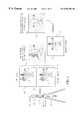
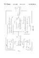
- FIG. 1illustrates an exemplary background suppression system equipped with a pair of cameras 11 a and 11 b that capture two color images: top image 13 b and bottom image 13 a .
- the contents in the two imagese.g., the respective person images 14 a and 14 b and computer images 15 a and 15 b , have a vertical dislocation if the edges of the image frames are aligned.
- This dislocationis called global disparity, and it is a function of the average distance of the scene from the camera.
- the systemneeds to find individual disparity corresponding to each visible surface point in the scene so that a depth image can be produced.
- the value of each pixel in the depth imagewill represent the distance from the corresponding scene point being projected to that pixel location.
- the depth imageis usually displayed as a gray scale image 10 as shown in FIG. 1 although it could also be displayed as a color image if the gray scale is color-coded.
- the depth image 10 in FIG. 1reveals that a person 17 is in the foreground with a higher gray scale and a computer 16 is in the background with a lower gray scale.
- the foregroundcan be separated from the background based on such depth values.
- the separation of foreground and backgroundcan lead to the formation of a foreground mask image 18 showing a depth mask 19 .
- the mask 19is then used to select the corresponding person region 21 of the bottom intensity image 13 a , and thereby produce a foreground image.
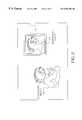
- the same maskis also used in compositing images as shown in FIG. 2 where the person 21 is added to the scene of a door 31 .
- the foreground mask image 18with the person depth mask 33 , is used to suppress a portion of the background in the door image 31 , thereby generating an intermediate image 34 in which a portion 35 of the door 36 is blocked out so that a person region 21 may be substituted in its place in the resultant composite image 41 .
- the suppressed backgroundis not a constant backing color scene.
- FIG. 3presents a scene with a person 63 in the foreground and a face picture 62 in the background.
- a face modelwould be used to single out the person in the image. If so, the face picture in the background will still be classified as part of the foreground and be selected as well.
- background suppressionfor this kind of scene would be possible. Accordingly, using the depth information of a scene is an effective way to extract foreground or suppress background of the scene image.
- Conventional depth recovery algorithmssee S B Marianne and M.
- What is therefore neededis a way to provide clear depth boundaries so that an accurate depth image, or map, can be formed.
- One useis to provide an image composite system wherein a foreground depth mask is formed by the means of analyzing the depth map of a scene. While this depth image, or map, would be used in the preferred embodiment in connection with an image composite system, it should be clearly recognized that such a depth image would be useful in a variety of situations, such as in the formation of virtual images. Consequently, the basic object is to provide a scene depth imaging system in which a scene depth map produced from a plurality of images provides more accurate depth data.
- a method and a computer program product for forming a depth image of a scenecomprises the steps of: (a) generating intensity parameters corresponding to image features in each of two intensity images of a scene, the intensity parameters in one image pairing with intensity parameters in the other image to form pairs of intensity parameters indicative of potential correspondence between features in the two intensity images; (b) eliminating one or more pairs of intensity parameters based on one or more constraints related to the feasibility of a valid match between the pairs of intensity parameters; (c) calculating a match score for each of the remaining pairs of intensity parameters; (d) processing the match scores of the remaining pairs of intensity parameters through a processing algorithm in order to find matched pairs of intensity parameters indicative of correspondence between the same features in the two intensity images; and (e) generating a depth image from the matched pairs of intensity parameters.
- a feature-point (edge point) guided matching methodis used to find corresponding pixels in at least two different images presenting a scene so that an initial feature-point depth map of the scene can be computed.
- a consistency testing procedureis employed after each of the images has produced an initial feature-point depth map of the scene.
- a less noisy, but sparse, feature-point depth mapis generated after the consistency testing procedure.
- the present inventionprovides a color property assisted depth propagation method to establish a complete feature-point depth map after the sparse feature-point depth map is obtained. This includes setting up a size adjustable window at each feature point that does not have a depth value; searching within the window for qualified feature points that have depth values and pass a color property checking; and computing depth for the feature point that does not have a depth value using the depth values of the qualified feature points.
- a method of separating the foreground and the background of the scene and suppressing the background based on the depth map of the sceneincludes sorting the depth values in the depth map in a descending or ascending order; eliminating depth values at some feature points based on an order statistics obtained from the ordered depth values; computing a histogram of the number of the feature points that still have depth values in a column-wise fashion, therefore to further deprive the depth values at feature points that do not belong to the majority of the remaining feature points that have depth values.
- a foreground depth maskis generated using the depth map containing the foreground feature points. For every pixel that does not have a depth value within the foreground region that is determined by the foreground feature points, a length extendable eight-nearest-neighbor search is conducted to collect a sufficient amount of feature points that have depth values and also satisfy a color criterion. An LMS (least median squared) estimation is then performed using the collected feature points to compute a depth value for that pixel.
- LMSleast median squared
- the current inventionpresents a method of forming a foreground depth mask, which in turn provides an alternative approach to the foreground extraction problem in the blue screen technology so that the need of a specially arranged environment with a constant backing color can be eliminated.
- This inventionutilizes a plurality of images associated with a scene imaging system to produce a depth map of the scene for which the foreground is to be separated from the background.
- This inventionenables the use of an arbitrary background rather than a uniformly colored one to extract the foreground object of interest.
- the image composite operation after the extractioncan be conducted in either 2D space or 3D space.
- FIG. 1is a schematic flow chart illustrating the successive stages of a foreground depth mask formation process in which a foreground depth mask (and the masked foreground intensity image) is produced by using a pair of intensity images captured by a pair of vertically displaced cameras;
- FIG. 2is a schematic flow chart illustrating the successive stages of an image composite process in which a composite image is produced by using a background image and the foreground depth mask (and the masked foreground intensity image) generated in the process illustrated in FIG. 1;
- FIG. 3is a pictorial view of a foreground object and a background object that has almost the same characteristics as the foreground;
- FIG. 4is a representation of the optical geometry associated with two images of a scene
- FIG. 5is a pictorial view of a pair of images in a process of searching corresponding points on a particular vertical scan line;
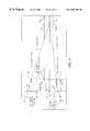
- FIG. 6is the flow chart for the major algorithmic steps which are performed to effect formation of a foreground depth mask in accordance with the method of the present invention
- FIGS. 7 a , 7 b , and 7 care score-matrices in a corresponding points search process for two images
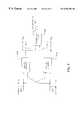
- FIG. 8is a more detailed flow chart for the first step in FIG. 6;
- FIG. 9is a more detailed flow chart for the second step in FIG. 6;
- FIG. 10is a more detailed flow chart for the third step in FIG. 6;
- FIG. 11is a diagrammatic illustration depicting a region that is to be interpolated to form the foreground depth mask
- FIG. 12is a perspective diagram of a computer system for implementing the present invention.
- FIG. 13is an example of a bipartite match network.
- the software programmay be stored in a computer readable storage medium, which may comprise, for example; magnetic storage media such as a magnetic disk (such as a floppy disk) or magnetic tape; optical storage media such as an optical disc, optical tape, or machine readable bar code; solid state electronic storage devices such as random access memory (RAM), or read only memory (ROM); or any other physical device or medium employed to store a computer program.
- a computer readable storage mediummay comprise, for example; magnetic storage media such as a magnetic disk (such as a floppy disk) or magnetic tape; optical storage media such as an optical disc, optical tape, or machine readable bar code; solid state electronic storage devices such as random access memory (RAM), or read only memory (ROM); or any other physical device or medium employed to store a computer program.
- the present inventionis preferably utilized on any well-known computer system, such a personal computer. Consequently, the computer system will not be discussed in detail herein. It is also instructive to note that the images are either directly input into the computer system (for example by a digital camera) or digitized before input into the computer system (for example by scanning an original, such as a silver halide film).
- the computer system 110includes a microprocessor-based unit 112 for receiving and processing software programs and for performing other processing functions.
- a display 114is electrically connected to the microprocessor-based unit 112 for displaying user-related information associated with the software.
- a keyboard 116is also connected to the microprocessor based unit 112 for permitting a user to input information to the software.
- a mouse 118may be used for moving a selector 120 on the display 114 and for selecting an item on which the selector 120 overlays, as is well known in the art.
- a compact disk-read only memory (CD-ROM) 122is connected to the microprocessor based unit 112 for receiving software programs and for providing a means of inputting the software programs and other information to the microprocessor based unit 112 via a compact disk 124 , which typically includes a software program.
- a floppy disk 126may also include a software program, and is inserted into the microprocessor-based unit 112 for inputting the software program.
- the microprocessor-based unit 112may be programmed, as is well known in the art, for storing the software program internally.
- the microprocessor-based unit 112may also have a network connection 127 , such as a telephone line, to an external network, such as a local area network or the Internet.
- a printer 128is connected to the microprocessor-based unit 112 for printing a hardcopy of the output of the computer system 110 .
- Imagesmay also be displayed on the display 114 via a personal computer card (PC card) 130 , such as, as it was formerly known, a PCMCIA card (based on the specifications of the Personal Computer Memory Card International Association) which contains digitized images electronically embodied in the card 130 .
- the PC card 130is ultimately inserted into the microprocessor based unit 112 for permitting visual display of an image on the display 114 .
- Imagesmay also be input via the compact disk 124 , the floppy disk 126 , or the network connection 127 .
- Any images stored in the PC card 130 , the floppy disk 126 or the computer disk 134 , or input through the network connection 127may have been obtained from a variety of sources, such as a digital camera (not shown) or a scanner (not shown).
- the imagesare obtained and processed in accordance with the following techniques and methods.
- FIG. 4shows the relationship between the camera 2D image coordinate system ( 73 a and 73 b ), for the two images 13 a and 13 b , and a 3D world coordinate system 79 . More specifically, the origin of the three-dimensional world coordinate system 79 is defined at the center of the line between a bottom camera nodal point 74 a and a top camera nodal point 74 b .
- the perspective projection of a 3D point 75(also shown as point p and represented by (x p , y p , z p ), which, without loss of generality, is in an XZ plane 78 ), is denoted by points (u 0p , v 0p ) 72 a and (u 1p , v 1p ) 72 b for the bottom image and the top image, respectively.
- the disparities associated with the point pare defined as
- the camerasare arranged in such a way that the value of one of the disparities is always considered to be zero.
- d u p0.
- the cameras 11 a , 11 bare assumed to be identical and share in the same optical specifications, e.g., focal length 81 and field of view.
- the baseline 82(i.e., the distance between the top and bottom images) of the two cameras 11 a , 11 b directly influences the resolution of depth estimates for each point in the captured image.
- the length of the baseline 82is a function of the expected distance from the camera to the objects of interest; i.e., a longer baseline is more useful than a short baseline for distant subjects.
- the camera systemhas an adjustable vertical baseline mechanism, such as an adjustable rack and pinion on a camera support.
- the amount of vertical baseline 82is displayed on a vernier gauge on the support.
- the baseline distance 82may be read from the vernier gauge and then employed, together with the focal length and the found disparity, in accurately determining the distance z p from the cameras 11 a , 11 b to the point 75 .
- the search for corresponding points in two imagesis conducted along a vertical scan line 95 as illustrated in FIG. 5 .
- the search dimensionsare thus reduced from 2 to 1.
- An algorithm with this arrangement for generating a depth map of the scene to suppress the backgroundis outlined in FIG. 6 . It comprises several key stages including feature points matching 216 , disparity propagation in feature space 217 , and foreground depth mask formation 218 .
- corresponding pointsmatching points
- the search of corresponding pointsis not conducted at every pixel of the image, but rather at the pixels that are feature points (edge points) of the intensity image, for instance, at the locations of vertical indices 91 a and 91 b (v 0i and v 1j ) in FIG. 5 .
- These feature pointscan be obtained in a conventional manner in a variety of ways, for example, by applying a gradient operator to each column (vertical scan-line) of the two images.
- the feature point mapcan be expressed as
- ⁇ k[ ⁇ 0 k , . . . , ⁇ n k , . . . , ⁇ N ⁇ 1 k ] Eq. (3)
- ⁇ n k[ ⁇ 0n k , . . . , ⁇ mn k , . . . , ⁇ (M ⁇ 1)n k ]′ Eq. (4)
- ⁇ mn k⁇ 1 if ⁇ ⁇ there ⁇ ⁇ is ⁇ ⁇ a ⁇ ⁇ feature ⁇ ⁇ point ⁇ ⁇ at ⁇ ⁇ location ⁇ ⁇ ( m , n ) 0 otherwise Eq. (5)
- N kis the number of feature points.
- the example feature points 92 a and 92 bare shown as F 0m and F 1n , respectively.
- the index for a specific columnis omitted, since the search of matching points is conducted one column at a time.
- the value of a feature point F kwis the vertical coordinate where the feature point resides. For instance:
- the origin of the image coordinate systemis at the center of the image as shown in FIG. 4 .
- the feature pointsare indexed from the top of the image towards the bottom, so there is an ordering property associated with the feature points:
- an intensity parameterhereinafter referred to as an intensity segment, starting from a feature point F ki to the subsequent feature point F k(i+1) by
- intensity segments 93 a and 93 bare shown as S 0m and S 1n , respectively.
- the general match procedureis explained below.
- N 0is the number of feature points on a specific column in the bottom image. Notice that S 0i starts at a feature point F 0i ; ends at a subsequent feature point F 0(i+1) . Every S 0i in the bottom image seeks a best match in the top image.
- the candidate segment in the top imageis constructed differently as
- S 1jstarts at a feature point F 1j ; ends at a pixel that is not necessarily the subsequent feature point F 1(j+1) .
- S 1jhas the same length as S 0i , which is required by the following score computing process. It should be pointed out that there are other methods to construct two equal length segments, such as decimation for the longer one to take out some elements, or interpolation for the shorter one to add some elements.
- N 0 ⁇ N 1 pairs of feature point guided segmentsto compare in order to get at most min(N 0 , N 1 ) pairs of best matches.
- Thiscan be represented by an N 0 ⁇ N 1 matrix 252 as shown in FIG. 7 ( a ), which represents pairs of intensity values indicative of potential correspondence between features in the two intensity images.
- Every pair of S 0i and S 1jis associated with a match score 255 as the matrix element (i.e., a match score value P ij for each matrix location as represented by a filled in circle in the matrix 252 ).
- the scoreis computed as
- SSDSum of Squared Difference
- ⁇is a parameter within the range [0,1]
- ⁇ (ij)denotes the support function for the true match of segments S 0i and S ij .
- ⁇ (ij)denotes the support function for the true match of segments S 0i and S ij .
- the termination time Tcan be determined either by a fixed iteration value or by checking if the score change is less than a preset.
- FIG. 7 ( b )shows the initial score matrix 253 after applying the disparity limit constraint.
- the bipartite match networktakes scores in FIG. 7 ( b ) as the initial values in blocks 182 and 184 (FIG. 13 ), and the iteration process ignores those pairs having zero score value. This modification not only reduces the computational complexity, but also reduces the false positive rate.
- the match processuses two match networks 302 a and 302 b followed by a consistency test block 308 as shown in FIG. 8 .
- Each match networktakes one image as the reference and the other image as the candidate, and produces a N 0 ⁇ N 1 match map 304 b or 304 a (i.e., either match map M 01 or match map M 10 ), an element of which will be set to 1 if there is a match claimed, otherwise the element is set to 0.
- the final match map 312 (M)is the result of an AND, ⁇ , operation being applied to the two individual match maps which are usually not identical. That is,
- bis the baseline 82
- fis a focal length 81 of the imaging system.
- the depth map or depth image Dhas validated (through consistency testing) depth values d mn at pixels that are feature points.
- the obtained depth imagehas very low spatial density, that is, a large amount of pixels including those pixels within the feature point set have not been assigned with depth values. In many cases a denser or a more completely defined depth field is desirable.
- a common practice in the machine vision community to tackle this problemis to fit surface patches to depth measurements that are available.
- a simple surface fitting approachmost likely will blur the depth boundaries (depth discontinuity) that are represented by depth values at those feature points.
- color properties of the original intensity imageare incorporated in depth surface fitting to preserve clear depth boundaries.
- the processsplits into two steps: propagation and interpolation.
- the propagation stepwill be explained below.
- the interpolation stepwill be discussed along with the depth mask formation procedure.
- an M ⁇ N hue map Han M ⁇ N purity map P for the original color (R,G,B) image.
- the propagation processstarts at an input terminal 408 .
- kis initialized as zero and adjustable from 1 to a predefined integer T K (see blocks 428 and 478 ).
- ⁇ k ⁇ i,j ⁇ k;i,j ⁇ 0 that have similar color property as d mn(block 428 ).
- the color property similarity measureis a simple distance testing in the color space by checking if the difference between d mn ⁇ D′′ and d (m+i)(n+j) ⁇ D′ is less than a predetermined threshold T H in hue domain and T p in purity domain (see block 428 ).
- T Ha predetermined threshold
- T pa predetermined threshold
- the foreground differentiation processis summarized in FIG. 10 .
- the generated depth map Dprovides sufficient spatial information to locate the foreground objects three dimensionally.
- the foreground objectscan be readily differentiated based on the depth values of the depth map D.
- ⁇be a vector containing the elements d mn ⁇ D′ that are assigned with depth values. Sort the vector ⁇ in a descending order (or ascending order) and then collect the top (or bottom) x% (between 10% to 30%) of its sorted elements (see blocks 558 and 568 ). Denote the collected elements by ⁇ overscore ( ⁇ ) ⁇ . Examine the elements d mn ⁇ D′.
- the result of the above processis a reduced set of D′ that contains essentially the foreground elements.
- D′contains essentially the foreground elements.
- uninterested objectsthat also belong to the foreground of the scene. These uninterested objects have to be removed before the formation of the foreground depth mask.
- the following stepsare carried out to correct this problem. Compute the histogram of the elements d mn ⁇ D′ column-wise after the foreground differentiation process is done. Find the valley(s) of the envelope of the computed histogram. Use the detected valley as a spatial indicator to delete unwanted foreground points.
- the resultis a further reduced set of D′ that contains the foreground points of interest.
- the color property assisted depth interpolationis carried out to form a foreground depth mask.
- the region 812where the remaining elements of D′ reside within the map 814 (D), (see FIG. 11 ).
- This region 812 ()has unconnected boundary points 802 (d ij ⁇ D′) as well as interior points 806 (d st ⁇ D′) that are all edge points of the foreground object of interest.
- This regionalso contains elements 804 (d mn ⁇ D′′).
- the goalis to estimate depth values for those points 804 (d mn ⁇ D′′) in the region 812 () based on the points 802 (d ij ⁇ D′) or 806 (d st ⁇ D′) through a color property assisted eight-nearest-neighbor LMS (least median squared) interpolation process.
- LMSleast median squared
- Nthe number of collected elements
- Mis a user selected number, 3 ⁇ M ⁇ 5
- Mthe number of collected elements
- ⁇ minmin ⁇ c ⁇ ⁇ ⁇ weighted ⁇ ⁇ median ⁇ q , p [ ( d qp ⁇ D ′ - ⁇ ⁇ ⁇ ( q , p ; ⁇ c ) ) 2 ⁇ residual ] ⁇ Eq. (21)
- ⁇ (q,p, ⁇ c )⁇ c1 +q ⁇ c2 +p ⁇ c3 +qp ⁇ c4
- d qpis one of the N elements including d ij and d st .
- the computer program product bearing the inventive algorithmswould either be provided directly to a user, who would use it in connection with the processing of images, or it would be used in a shared setting, where a customer would bring pictures and/or negatives to the shared computer for scanning and enhancement, or would directly enter digital scan data into the shared computer.
- the algorithmscould be made available in a web-based version of the product, where either the algorithms are downloaded via the network connection to the user or the algorithm computation is done on a server in a web-based environment.
Landscapes
- Engineering & Computer Science (AREA)
- Physics & Mathematics (AREA)
- General Physics & Mathematics (AREA)
- Theoretical Computer Science (AREA)
- Computer Vision & Pattern Recognition (AREA)
- Multimedia (AREA)
- Image Analysis (AREA)
- Image Processing (AREA)
Abstract
Description


| 10 | ||||
| 11a, | cameras | |||
| 13a, | images | |||
| 14a, | person images | |||
| 15a, 15b | computer images | |||
| 17 | person | |||
| 16 | ||||
| 18 | foreground mask image | |||
| 19 | ||||
| 20 | composited | |||
| 21 | ||||
| 31 | ||||
| 34 | ||||
| 35 | ||||
| 36 | ||||
| 41 | ||||
| 62 | ||||
| 63 | ||||
| 72a, 72b | ||||
| 73a, 73b | 2D image coordinate system | |||
| 73 | 3D world coordinate | |||
| 74a, 74b | ||||
| 75 | 3D point | |||
| 76 | ||||
| 78 | XZ plane | |||
| 81 | ||||
| 82 | baseline | |||
| 91 | ||||
| 92a, | feature points | |||
| 93a, | intensity segments | |||
| 95 | ||||
| 98a | ||||
| 98b | ||||
| 110 | ||||
| 112 | ||||
| 114 | ||||
| 116 | ||||
| 118 | ||||
| 120 | ||||
| 122 | CD- | |||
| 124 | ||||
| 126 | ||||
| 127 | ||||
| 128 | ||||
| 130 | ||||
| 216 | feature points matching | |||
| 217 | ||||
| 218 | foreground mask formats | |||
| 252 | ||||
| 253 | ||||
| 255 | ||||
| 302a, 302b | ||||
| 304a, 304b | ||||
| 308 | ||||
| 312 | ||||
| 408 | ||||
| 418 | ||||
| 428 | ||||
| 438 | ||||
| 458 | ||||
| 468 | ||||
| 478 | ||||
| 558 | ||||
| 568 | ||||
| 588 | ||||
| 802 | ||||
| 804 | element | |||
| 806 | ||||
| 812 | ||||
| 814 | depth map | |||
Claims (40)
Priority Applications (3)
| Application Number | Priority Date | Filing Date | Title |
|---|---|---|---|
| US09/382,451US6556704B1 (en) | 1999-08-25 | 1999-08-25 | Method for forming a depth image from digital image data |
| US10/337,505US6891966B2 (en) | 1999-08-25 | 2003-01-07 | Method for forming a depth image from digital image data |
| US11/048,166US7236622B2 (en) | 1999-08-25 | 2005-02-01 | Method for forming a depth image |
Applications Claiming Priority (1)
| Application Number | Priority Date | Filing Date | Title |
|---|---|---|---|
| US09/382,451US6556704B1 (en) | 1999-08-25 | 1999-08-25 | Method for forming a depth image from digital image data |
Related Child Applications (1)
| Application Number | Title | Priority Date | Filing Date |
|---|---|---|---|
| US10/337,505DivisionUS6891966B2 (en) | 1999-08-25 | 2003-01-07 | Method for forming a depth image from digital image data |
Publications (1)
| Publication Number | Publication Date |
|---|---|
| US6556704B1true US6556704B1 (en) | 2003-04-29 |
Family
ID=23509007
Family Applications (2)
| Application Number | Title | Priority Date | Filing Date |
|---|---|---|---|
| US09/382,451Expired - LifetimeUS6556704B1 (en) | 1999-08-25 | 1999-08-25 | Method for forming a depth image from digital image data |
| US10/337,505Expired - LifetimeUS6891966B2 (en) | 1999-08-25 | 2003-01-07 | Method for forming a depth image from digital image data |
Family Applications After (1)
| Application Number | Title | Priority Date | Filing Date |
|---|---|---|---|
| US10/337,505Expired - LifetimeUS6891966B2 (en) | 1999-08-25 | 2003-01-07 | Method for forming a depth image from digital image data |
Country Status (1)
| Country | Link |
|---|---|
| US (2) | US6556704B1 (en) |
Cited By (118)
| Publication number | Priority date | Publication date | Assignee | Title |
|---|---|---|---|---|
| US20010036319A1 (en)* | 2000-03-21 | 2001-11-01 | Shinichi Sakaida | Coding and decoding of moving pictures based on sprite coding |
| US20020071125A1 (en)* | 2000-10-13 | 2002-06-13 | Frank Sieckmann | Method and apparatus for optical measurement of a surface profile of a specimen |
| US20020118875A1 (en)* | 2000-12-21 | 2002-08-29 | Wilensky Gregg D. | Image extraction from complex scenes in digital video |
| US20020159101A1 (en)* | 2001-04-25 | 2002-10-31 | Timothy Alderson | Scene-based non-uniformity correction for detector arrays |
| US20020159651A1 (en)* | 2001-04-25 | 2002-10-31 | Tener Gene D. | Extended range image processing for electro-optical systems |
| US20020159648A1 (en)* | 2001-04-25 | 2002-10-31 | Timothy Alderson | Dynamic range compression |
| US20020175921A1 (en)* | 1999-12-10 | 2002-11-28 | Li-Qun Xu | Image processing |
| US20030012277A1 (en)* | 2001-07-04 | 2003-01-16 | Matsushita Electric Industrial Co., Ltd. | Image signal coding method, image signal coding apparatus and storage medium |
| US20030204384A1 (en)* | 2002-04-24 | 2003-10-30 | Yuri Owechko | High-performance sensor fusion architecture |
| US20040062439A1 (en)* | 2002-09-27 | 2004-04-01 | Eastman Kodak Company | Method and system for generating a foreground mask for a composite image |
| US20040095999A1 (en)* | 2001-01-24 | 2004-05-20 | Erick Piehl | Method for compressing video information |
| US20040104997A1 (en)* | 2002-05-13 | 2004-06-03 | Jo Versavel | Method and device for detecting the presence of an object on a runway |
| KR100442542B1 (en)* | 2002-04-12 | 2004-07-30 | 학교법인 한양학원 | Method for Identifying Biological Information Using Bipartite Matching |
| US6771818B1 (en)* | 2000-04-04 | 2004-08-03 | Microsoft Corporation | System and process for identifying and locating people or objects in a scene by selectively clustering three-dimensional regions |
| US20040155962A1 (en)* | 2003-02-11 | 2004-08-12 | Marks Richard L. | Method and apparatus for real time motion capture |
| US20040179739A1 (en)* | 2001-05-23 | 2004-09-16 | Piotr Wilinski | Depth map computation |
| US6813377B1 (en)* | 1999-08-06 | 2004-11-02 | Cognex Corporation | Methods and apparatuses for generating a model of an object from an image of the object |
| US20040257360A1 (en)* | 2001-10-22 | 2004-12-23 | Frank Sieckmann | Method and device for producing light-microscopy, three-dimensional images |
| US20050068544A1 (en)* | 2003-09-25 | 2005-03-31 | Gunter Doemens | Panoramic scanner |
| US20050076012A1 (en)* | 2003-09-23 | 2005-04-07 | Udi Manber | Personalized searchable library with highlighting capabilities |
| US20050078865A1 (en)* | 2003-10-08 | 2005-04-14 | Antonio Criminisi | Gaze manipulation |
| US6891966B2 (en)* | 1999-08-25 | 2005-05-10 | Eastman Kodak Company | Method for forming a depth image from digital image data |
| US6898333B1 (en) | 1999-08-06 | 2005-05-24 | Cognex Corporation | Methods and apparatus for determining the orientation of an object in an image |
| US20050110801A1 (en)* | 2003-11-20 | 2005-05-26 | I-Jong Lin | Methods and systems for processing displayed images |
| US20050157204A1 (en)* | 2004-01-16 | 2005-07-21 | Sony Computer Entertainment Inc. | Method and apparatus for optimizing capture device settings through depth information |
| US20050219391A1 (en)* | 2004-04-01 | 2005-10-06 | Microsoft Corporation | Digital cameras with luminance correction |
| US20050220359A1 (en)* | 2004-04-01 | 2005-10-06 | Microsoft Corporation | Luminance correction |
| US20060038833A1 (en)* | 2004-08-19 | 2006-02-23 | Mallinson Dominic S | Portable augmented reality device and method |
| US20060072022A1 (en)* | 2004-10-06 | 2006-04-06 | Yoshiaki Iwai | Image processing method and image processing device |
| US20060153450A1 (en)* | 2004-11-03 | 2006-07-13 | Tyzx, Inc. | Integrated image processor |
| US20060210148A1 (en)* | 2005-03-07 | 2006-09-21 | Kabushiki Kaisha Toshiba | Three-dimensional model generating apparatus, method and program |
| US20060212435A1 (en)* | 2003-09-23 | 2006-09-21 | Williams Brian R | Automated monitoring and control of access to content from a source |
| WO2006100623A1 (en)* | 2005-03-24 | 2006-09-28 | Koninklijke Philips Electronics N.V. | System and method for combining two or more digital images |
| US20060230358A1 (en)* | 2003-05-02 | 2006-10-12 | Jorn Sacher | System for inspecting a printed image |
| US20060252541A1 (en)* | 2002-07-27 | 2006-11-09 | Sony Computer Entertainment Inc. | Method and system for applying gearing effects to visual tracking |
| US20060277571A1 (en)* | 2002-07-27 | 2006-12-07 | Sony Computer Entertainment Inc. | Computer image and audio processing of intensity and input devices for interfacing with a computer program |
| US20070047840A1 (en)* | 2005-08-24 | 2007-03-01 | Siemens Corporate Research Inc | System and method for salient region feature based 3d multi modality registration of medical images |
| US20070075966A1 (en)* | 2002-07-18 | 2007-04-05 | Sony Computer Entertainment Inc. | Hand-held computer interactive device |
| US20070183679A1 (en)* | 2004-02-05 | 2007-08-09 | Vodafone K.K. | Image processing method, image processing device and mobile communication terminal |
| US20070286476A1 (en)* | 2006-06-07 | 2007-12-13 | Samsung Electronics Co., Ltd. | Method and device for generating a disparity map from stereo images and stereo matching method and device therefor |
| US20070298882A1 (en)* | 2003-09-15 | 2007-12-27 | Sony Computer Entertainment Inc. | Methods and systems for enabling direction detection when interfacing with a computer program |
| US20080009348A1 (en)* | 2002-07-31 | 2008-01-10 | Sony Computer Entertainment Inc. | Combiner method for altering game gearing |
| WO2008009981A1 (en)* | 2006-07-21 | 2008-01-24 | Snell & Wilcox Limited | Picture attribute allocation |
| US20080037862A1 (en)* | 2006-06-29 | 2008-02-14 | Sungkyunkwan University Foundation For Corporate Collaboration | Extensible system and method for stereo matching in real-time |
| US20080056578A1 (en)* | 2006-09-05 | 2008-03-06 | Michael Shilman | Constraint-based correction of handwriting recognition errors |
| US20080088718A1 (en)* | 2006-10-17 | 2008-04-17 | Cazier Robert P | Template Creator For Digital Cameras |
| US20080094353A1 (en)* | 2002-07-27 | 2008-04-24 | Sony Computer Entertainment Inc. | Methods for interfacing with a program using a light input device |
| US20080100720A1 (en)* | 2006-10-30 | 2008-05-01 | Brokish Kevin M | Cutout Effect For Digital Photographs |
| US20080180533A1 (en)* | 2007-01-31 | 2008-07-31 | Murray Dean Craig | Systems And Methods Of Customizing A Color Palette On A Digital Camera |
| US20080212895A1 (en)* | 2007-01-09 | 2008-09-04 | Lockheed Martin Corporation | Image data processing techniques for highly undersampled images |
| US20080253617A1 (en)* | 2005-09-29 | 2008-10-16 | Koninklijke Philips Electronics, N.V. | Method and Apparatus for Determining the Shot Type of an Image |
| US20080261693A1 (en)* | 2008-05-30 | 2008-10-23 | Sony Computer Entertainment America Inc. | Determination of controller three-dimensional location using image analysis and ultrasonic communication |
| US20090046895A1 (en)* | 2007-08-10 | 2009-02-19 | Leica Geosystems Ag | Method and measurement system for contactless coordinate measurement on an object surface |
| CN100468457C (en)* | 2007-02-08 | 2009-03-11 | 深圳大学 | Method for matching depth image |
| US20090158220A1 (en)* | 2007-12-17 | 2009-06-18 | Sony Computer Entertainment America | Dynamic three-dimensional object mapping for user-defined control device |
| US20090168027A1 (en)* | 2007-12-28 | 2009-07-02 | Motorola, Inc. | Projector system employing depth perception to detect speaker position and gestures |
| US20090179998A1 (en)* | 2003-06-26 | 2009-07-16 | Fotonation Vision Limited | Modification of Post-Viewing Parameters for Digital Images Using Image Region or Feature Information |
| US20090201384A1 (en)* | 2008-02-13 | 2009-08-13 | Samsung Electronics Co., Ltd. | Method and apparatus for matching color image and depth image |
| US20090215533A1 (en)* | 2008-02-27 | 2009-08-27 | Gary Zalewski | Methods for capturing depth data of a scene and applying computer actions |
| US20090244309A1 (en)* | 2006-08-03 | 2009-10-01 | Benoit Maison | Method and Device for Identifying and Extracting Images of multiple Users, and for Recognizing User Gestures |
| US20090298590A1 (en)* | 2005-10-26 | 2009-12-03 | Sony Computer Entertainment Inc. | Expandable Control Device Via Hardware Attachment |
| US20100119142A1 (en)* | 2008-11-11 | 2010-05-13 | Sean Miceli | Monitoring Multiple Similar Objects Using Image Templates |
| US20100119114A1 (en)* | 2008-11-12 | 2010-05-13 | Paul Ardis | Determining relative depth of points in multiple videos |
| US20100165150A1 (en)* | 2003-06-26 | 2010-07-01 | Fotonation Vision Limited | Detecting orientation of digital images using face detection information |
| US7760248B2 (en) | 2002-07-27 | 2010-07-20 | Sony Computer Entertainment Inc. | Selective sound source listening in conjunction with computer interactive processing |
| US20100241692A1 (en)* | 2009-03-20 | 2010-09-23 | Sony Computer Entertainment America Inc., a Delaware Corporation | Methods and systems for dynamically adjusting update rates in multi-player network gaming |
| US20100245609A1 (en)* | 2009-03-26 | 2010-09-30 | Texas Instruments Incorporated | Digital Image Segmentation Using Flash |
| US20100261527A1 (en)* | 2009-04-10 | 2010-10-14 | Sony Computer Entertainment America Inc., a Delaware Corporation | Methods and systems for enabling control of artificial intelligence game characters |
| US20100304868A1 (en)* | 2009-05-29 | 2010-12-02 | Sony Computer Entertainment America Inc. | Multi-positional three-dimensional controller |
| US20110002506A1 (en)* | 2008-07-30 | 2011-01-06 | Tessera Technologies Ireland Limited | Eye Beautification |
| US20110002541A1 (en)* | 2007-12-20 | 2011-01-06 | Koninklijke Philips Electronics N.V. | Segmentation of image data |
| US7874917B2 (en) | 2003-09-15 | 2011-01-25 | Sony Computer Entertainment Inc. | Methods and systems for enabling depth and direction detection when interfacing with a computer program |
| US20110025830A1 (en)* | 2009-07-31 | 2011-02-03 | 3Dmedia Corporation | Methods, systems, and computer-readable storage media for generating stereoscopic content via depth map creation |
| US20110025825A1 (en)* | 2009-07-31 | 2011-02-03 | 3Dmedia Corporation | Methods, systems, and computer-readable storage media for creating three-dimensional (3d) images of a scene |
| US7883415B2 (en) | 2003-09-15 | 2011-02-08 | Sony Computer Entertainment Inc. | Method and apparatus for adjusting a view of a scene being displayed according to tracked head motion |
| US20110044531A1 (en)* | 2007-11-09 | 2011-02-24 | Thomson Licensing | System and method for depth map extraction using region-based filtering |
| US20110081042A1 (en)* | 2009-10-07 | 2011-04-07 | Samsung Electronics Co., Ltd. | Apparatus and method for adjusting depth |
| WO2011096892A1 (en)* | 2010-02-05 | 2011-08-11 | Creative Technology Ltd | Device and method for scanning an object on a working surface |
| US20110227914A1 (en)* | 2008-12-02 | 2011-09-22 | Koninklijke Philips Electronics N.V. | Generation of a depth map |
| US8072470B2 (en) | 2003-05-29 | 2011-12-06 | Sony Computer Entertainment Inc. | System and method for providing a real-time three-dimensional interactive environment |
| US8142288B2 (en) | 2009-05-08 | 2012-03-27 | Sony Computer Entertainment America Llc | Base station movement detection and compensation |
| US20120163672A1 (en)* | 2010-12-22 | 2012-06-28 | David Mckinnon | Depth Estimate Determination, Systems and Methods |
| US8274552B2 (en) | 2010-12-27 | 2012-09-25 | 3Dmedia Corporation | Primary and auxiliary image capture devices for image processing and related methods |
| US8287373B2 (en) | 2008-12-05 | 2012-10-16 | Sony Computer Entertainment Inc. | Control device for communicating visual information |
| US8310656B2 (en) | 2006-09-28 | 2012-11-13 | Sony Computer Entertainment America Llc | Mapping movements of a hand-held controller to the two-dimensional image plane of a display screen |
| US8313380B2 (en) | 2002-07-27 | 2012-11-20 | Sony Computer Entertainment America Llc | Scheme for translating movements of a hand-held controller into inputs for a system |
| US8368753B2 (en) | 2008-03-17 | 2013-02-05 | Sony Computer Entertainment America Llc | Controller with an integrated depth camera |
| US8393964B2 (en) | 2009-05-08 | 2013-03-12 | Sony Computer Entertainment America Llc | Base station for position location |
| US8570378B2 (en) | 2002-07-27 | 2013-10-29 | Sony Computer Entertainment Inc. | Method and apparatus for tracking three-dimensional movements of an object using a depth sensing camera |
| US8686939B2 (en) | 2002-07-27 | 2014-04-01 | Sony Computer Entertainment Inc. | System, method, and apparatus for three-dimensional input control |
| WO2012005947A3 (en)* | 2010-07-07 | 2014-06-26 | Spinella Ip Holdings, Inc. | System and method for transmission, processing, and rendering of stereoscopic and multi-view images |
| US8781151B2 (en) | 2006-09-28 | 2014-07-15 | Sony Computer Entertainment Inc. | Object detection using video input combined with tilt angle information |
| US8797260B2 (en) | 2002-07-27 | 2014-08-05 | Sony Computer Entertainment Inc. | Inertially trackable hand-held controller |
| US20140219559A1 (en)* | 2010-09-02 | 2014-08-07 | Edge 3 Technologies, Inc. | Apparatus and Method for Segmenting an Image |
| US9020240B2 (en) | 2007-08-10 | 2015-04-28 | Leica Geosystems Ag | Method and surveying system for noncontact coordinate measurement on an object surface |
| EP2778603A4 (en)* | 2011-11-11 | 2015-06-03 | Hitachi Automotive Systems Ltd | IMAGE PROCESSING APPARATUS AND IMAGE PROCESSING METHOD |
| US20150248775A1 (en)* | 2012-10-03 | 2015-09-03 | Holition Limited | Image processing |
| US9185388B2 (en) | 2010-11-03 | 2015-11-10 | 3Dmedia Corporation | Methods, systems, and computer program products for creating three-dimensional video sequences |
| US20150379720A1 (en)* | 2013-01-31 | 2015-12-31 | Threevolution Llc | Methods for converting two-dimensional images into three-dimensional images |
| US9344701B2 (en) | 2010-07-23 | 2016-05-17 | 3Dmedia Corporation | Methods, systems, and computer-readable storage media for identifying a rough depth map in a scene and for determining a stereo-base distance for three-dimensional (3D) content creation |
| US9380292B2 (en) | 2009-07-31 | 2016-06-28 | 3Dmedia Corporation | Methods, systems, and computer-readable storage media for generating three-dimensional (3D) images of a scene |
| US9393487B2 (en) | 2002-07-27 | 2016-07-19 | Sony Interactive Entertainment Inc. | Method for mapping movements of a hand-held controller to game commands |
| WO2017007048A1 (en)* | 2015-07-08 | 2017-01-12 | 재단법인 다차원 스마트 아이티 융합시스템 연구단 | Method and apparatus for determining depth in image using depth propagation direction of edge |
| WO2017007047A1 (en)* | 2015-07-08 | 2017-01-12 | 재단법인 다차원 스마트 아이티 융합시스템 연구단 | Spatial depth non-uniformity compensation method and device using jittered comparison |
| US9699434B2 (en) | 2009-10-07 | 2017-07-04 | Samsung Electronics Co., Ltd. | Apparatus and method for adjusting depth |
| US9832454B2 (en)* | 2014-11-20 | 2017-11-28 | Samsung Electronics Co., Ltd. | Method and apparatus for matching stereo images |
| US20170353670A1 (en)* | 2016-06-07 | 2017-12-07 | Disney Enterprises, Inc. | Video segmentation from an uncalibrated camera array |
| US9842400B2 (en) | 2015-01-27 | 2017-12-12 | Samsung Electronics Co., Ltd. | Method and apparatus for determining disparity |
| CN108460737A (en)* | 2018-02-08 | 2018-08-28 | 上海爱优威软件开发有限公司 | A kind of intelligent filter method and system of CNN-LMS picture noises |
| US10200671B2 (en) | 2010-12-27 | 2019-02-05 | 3Dmedia Corporation | Primary and auxiliary image capture devices for image processing and related methods |
| US10279254B2 (en) | 2005-10-26 | 2019-05-07 | Sony Interactive Entertainment Inc. | Controller having visually trackable object for interfacing with a gaming system |
| CN110999276A (en)* | 2017-09-08 | 2020-04-10 | 苹果公司 | Augmented reality self-camera |
| USRE48417E1 (en) | 2006-09-28 | 2021-02-02 | Sony Interactive Entertainment Inc. | Object direction using video input combined with tilt angle information |
| US11057604B2 (en)* | 2017-09-27 | 2021-07-06 | SZ DJI Technology Co., Ltd. | Image processing method and device |
| US11120280B2 (en)* | 2019-11-15 | 2021-09-14 | Argo AI, LLC | Geometry-aware instance segmentation in stereo image capture processes |
| US11164326B2 (en)* | 2018-12-18 | 2021-11-02 | Samsung Electronics Co., Ltd. | Method and apparatus for calculating depth map |
| US11200690B2 (en)* | 2018-12-03 | 2021-12-14 | Canon Kabushiki Kaisha | Image processing apparatus, three-dimensional shape data generation method, and non-transitory computer readable storage medium |
| CN114491318A (en)* | 2021-12-16 | 2022-05-13 | 北京百度网讯科技有限公司 | Determination method, device, device and storage medium of target information |
Families Citing this family (83)
| Publication number | Priority date | Publication date | Assignee | Title |
|---|---|---|---|---|
| JP4531897B2 (en)* | 1999-12-27 | 2010-08-25 | パナソニック株式会社 | Person tracking device, person tracking method, and recording medium recording the program |
| US7342489B1 (en) | 2001-09-06 | 2008-03-11 | Siemens Schweiz Ag | Surveillance system control unit |
| US7639889B2 (en)* | 2004-11-10 | 2009-12-29 | Fotonation Ireland Ltd. | Method of notifying users regarding motion artifacts based on image analysis |
| US7606417B2 (en) | 2004-08-16 | 2009-10-20 | Fotonation Vision Limited | Foreground/background segmentation in digital images with differential exposure calculations |
| US8989516B2 (en)* | 2007-09-18 | 2015-03-24 | Fotonation Limited | Image processing method and apparatus |
| US7680342B2 (en) | 2004-08-16 | 2010-03-16 | Fotonation Vision Limited | Indoor/outdoor classification in digital images |
| US7636486B2 (en)* | 2004-11-10 | 2009-12-22 | Fotonation Ireland Ltd. | Method of determining PSF using multiple instances of a nominally similar scene |
| US8180173B2 (en) | 2007-09-21 | 2012-05-15 | DigitalOptics Corporation Europe Limited | Flash artifact eye defect correction in blurred images using anisotropic blurring |
| US8264576B2 (en)* | 2007-03-05 | 2012-09-11 | DigitalOptics Corporation Europe Limited | RGBW sensor array |
| US8199222B2 (en)* | 2007-03-05 | 2012-06-12 | DigitalOptics Corporation Europe Limited | Low-light video frame enhancement |
| US8417055B2 (en)* | 2007-03-05 | 2013-04-09 | DigitalOptics Corporation Europe Limited | Image processing method and apparatus |
| US9160897B2 (en)* | 2007-06-14 | 2015-10-13 | Fotonation Limited | Fast motion estimation method |
| KR101168384B1 (en)* | 2004-03-12 | 2012-07-25 | 코닌클리케 필립스 일렉트로닉스 엔.브이. | Method of generating a depth map, depth map generating unit, image processing apparatus and computer program product |
| ATE404950T1 (en)* | 2004-06-11 | 2008-08-15 | Saab Ab | COMPUTER MODELING OF PHYSICAL SCENES |
| US7333652B2 (en)* | 2004-08-03 | 2008-02-19 | Sony Corporation | System and method for efficiently performing a depth map recovery procedure |
| US7639888B2 (en)* | 2004-11-10 | 2009-12-29 | Fotonation Ireland Ltd. | Method and apparatus for initiating subsequent exposures based on determination of motion blurring artifacts |
| WO2006058292A2 (en)* | 2004-11-29 | 2006-06-01 | Purdue Research Foundation | Methods for retrieving shapes and drawings |
| JP4283785B2 (en)* | 2005-05-10 | 2009-06-24 | 株式会社マーキュリーシステム | Stereoscopic image generation apparatus and program |
| US7822000B2 (en)* | 2005-06-30 | 2010-10-26 | Symbol Technologies, Inc. | Time division multiplexing for access ports in a wireless network |
| US7720282B2 (en)* | 2005-08-02 | 2010-05-18 | Microsoft Corporation | Stereo image segmentation |
| US7929801B2 (en)* | 2005-08-15 | 2011-04-19 | Sony Corporation | Depth information for auto focus using two pictures and two-dimensional Gaussian scale space theory |
| JP4757008B2 (en)* | 2005-12-13 | 2011-08-24 | キヤノン株式会社 | Document management method and apparatus |
| US7692696B2 (en)* | 2005-12-27 | 2010-04-06 | Fotonation Vision Limited | Digital image acquisition system with portrait mode |
| WO2007095477A2 (en)* | 2006-02-14 | 2007-08-23 | Fotonation Vision Limited | Image blurring |
| IES20060558A2 (en) | 2006-02-14 | 2006-11-01 | Fotonation Vision Ltd | Image blurring |
| US20070189750A1 (en)* | 2006-02-16 | 2007-08-16 | Sony Corporation | Method of and apparatus for simultaneously capturing and generating multiple blurred images |
| US7616254B2 (en)* | 2006-03-16 | 2009-11-10 | Sony Corporation | Simple method for calculating camera defocus from an image scene |
| IES20060564A2 (en)* | 2006-05-03 | 2006-11-01 | Fotonation Vision Ltd | Improved foreground / background separation |
| IES20070229A2 (en)* | 2006-06-05 | 2007-10-03 | Fotonation Vision Ltd | Image acquisition method and apparatus |
| US7711201B2 (en)* | 2006-06-22 | 2010-05-04 | Sony Corporation | Method of and apparatus for generating a depth map utilized in autofocusing |
| CN101523436A (en)* | 2006-10-02 | 2009-09-02 | 皇家飞利浦电子股份有限公司 | Method and filter for recovery of disparities in a video stream |
| US8077964B2 (en)* | 2007-03-19 | 2011-12-13 | Sony Corporation | Two dimensional/three dimensional digital information acquisition and display device |
| US7773118B2 (en)* | 2007-03-25 | 2010-08-10 | Fotonation Vision Limited | Handheld article with movement discrimination |
| US20080309770A1 (en)* | 2007-06-18 | 2008-12-18 | Fotonation Vision Limited | Method and apparatus for simulating a camera panning effect |
| US8854425B2 (en)* | 2007-07-26 | 2014-10-07 | Koninklijke Philips N.V. | Method and apparatus for depth-related information propagation |
| DE102007045834B4 (en) | 2007-09-25 | 2012-01-26 | Metaio Gmbh | Method and device for displaying a virtual object in a real environment |
| DE102007045835B4 (en) | 2007-09-25 | 2012-12-20 | Metaio Gmbh | Method and device for displaying a virtual object in a real environment |
| US20090148823A1 (en)* | 2007-12-05 | 2009-06-11 | Wall Street Institute, Kft | System, method, and computer program product for providing distributed learning content |
| TWI362628B (en)* | 2007-12-28 | 2012-04-21 | Ind Tech Res Inst | Methof for producing an image with depth by using 2d image |
| JP4956452B2 (en)* | 2008-01-25 | 2012-06-20 | 富士重工業株式会社 | Vehicle environment recognition device |
| JP4876080B2 (en)* | 2008-01-25 | 2012-02-15 | 富士重工業株式会社 | Environment recognition device |
| US8300975B2 (en)* | 2008-01-30 | 2012-10-30 | Siemens Corporation | Piecewise smooth Mumford-Shah on an arbitrary graph |
| US8280194B2 (en) | 2008-04-29 | 2012-10-02 | Sony Corporation | Reduced hardware implementation for a two-picture depth map algorithm |
| US8073243B2 (en)* | 2008-05-30 | 2011-12-06 | General Instrument Corporation | Replacing image information in a captured image |
| TW201005673A (en)* | 2008-07-18 | 2010-02-01 | Ind Tech Res Inst | Example-based two-dimensional to three-dimensional image conversion method, computer readable medium therefor, and system |
| US8265380B1 (en)* | 2008-08-14 | 2012-09-11 | Adobe Systems Incorporated | Reuse of image processing information |
| US9025043B2 (en)* | 2008-09-24 | 2015-05-05 | Nikon Corporation | Image segmentation from focus varied images using graph cuts |
| US20100079448A1 (en)* | 2008-09-30 | 2010-04-01 | Liang-Gee Chen | 3D Depth Generation by Block-based Texel Density Analysis |
| US8194995B2 (en)* | 2008-09-30 | 2012-06-05 | Sony Corporation | Fast camera auto-focus |
| US8553093B2 (en)* | 2008-09-30 | 2013-10-08 | Sony Corporation | Method and apparatus for super-resolution imaging using digital imaging devices |
| KR101502597B1 (en)* | 2008-11-13 | 2015-03-13 | 삼성전자주식회사 | Wide depth of field 3d display apparatus and method |
| US8294767B2 (en)* | 2009-01-30 | 2012-10-23 | Microsoft Corporation | Body scan |
| TWI457853B (en)* | 2009-03-24 | 2014-10-21 | Ind Tech Res Inst | Image processing method for providing depth information and image processing system using the same |
| CA2772607A1 (en)* | 2009-09-01 | 2011-03-10 | Prime Focus Vfx Services Ii Inc. | System and process for transforming two-dimensional images into three-dimensional images |
| US8355565B1 (en)* | 2009-10-29 | 2013-01-15 | Hewlett-Packard Development Company, L.P. | Producing high quality depth maps |
| CN101840574B (en)* | 2010-04-16 | 2012-05-23 | 西安电子科技大学 | Depth estimation method based on edge pixel characteristics |
| US9485495B2 (en)* | 2010-08-09 | 2016-11-01 | Qualcomm Incorporated | Autofocus for stereo images |
| US8917941B2 (en)* | 2010-09-28 | 2014-12-23 | Siemens Aktiengesellschaft | System and method for shape measurements on thick MPR images |
| US8578299B2 (en)* | 2010-10-08 | 2013-11-05 | Industrial Technology Research Institute | Method and computing device in a system for motion detection |
| US20120105581A1 (en)* | 2010-10-29 | 2012-05-03 | Sony Corporation | 2d to 3d image and video conversion using gps and dsm |
| US8666191B2 (en)* | 2011-03-02 | 2014-03-04 | Canon Kabushiki Kaisha | Systems and methods for image capturing |
| US8977629B2 (en)* | 2011-05-24 | 2015-03-10 | Ebay Inc. | Image-based popularity prediction |
| TWI493505B (en)* | 2011-06-20 | 2015-07-21 | Mstar Semiconductor Inc | Image processing method and image processing apparatus thereof |
| CN102510506B (en)* | 2011-09-30 | 2014-04-16 | 北京航空航天大学 | Virtual and real occlusion handling method based on binocular image and range information |
| US20130169760A1 (en)* | 2012-01-04 | 2013-07-04 | Lloyd Watts | Image Enhancement Methods And Systems |
| US20130329985A1 (en)* | 2012-06-07 | 2013-12-12 | Microsoft Corporation | Generating a three-dimensional image |
| KR20140137738A (en)* | 2013-05-23 | 2014-12-03 | 삼성전자주식회사 | Image display method, image display apparatus and recordable media |
| US10021366B2 (en) | 2014-05-02 | 2018-07-10 | Eys3D Microelectronics, Co. | Image process apparatus |
| US9679387B2 (en)* | 2015-02-12 | 2017-06-13 | Mitsubishi Electric Research Laboratories, Inc. | Depth-weighted group-wise principal component analysis for video foreground/background separation |
| CN105844616B (en)* | 2016-03-17 | 2019-06-11 | 湖南优象科技有限公司 | Binocular Stereo Matching Algorithm and device under laser light scattering spot auxiliary |
| CN105894503B (en)* | 2016-03-30 | 2019-10-01 | 江苏大学 | A kind of restorative procedure of pair of Kinect plant colour and depth detection image |
| JP7013578B2 (en)* | 2017-11-03 | 2022-01-31 | グーグル エルエルシー | Aperture monitoring for single-view depth prediction |
| US10896492B2 (en) | 2018-11-09 | 2021-01-19 | Qwake Technologies, Llc | Cognitive load reducing platform having image edge enhancement |
| US10417497B1 (en) | 2018-11-09 | 2019-09-17 | Qwake Technologies | Cognitive load reducing platform for first responders |
| US11890494B2 (en) | 2018-11-09 | 2024-02-06 | Qwake Technologies, Inc. | Retrofittable mask mount system for cognitive load reducing platform |
| CN109823306A (en)* | 2019-02-22 | 2019-05-31 | 广东远峰汽车电子有限公司 | Vehicle door unlocking method, device and system and readable storage medium |
| CN113939852A (en)* | 2019-06-12 | 2022-01-14 | 欧姆龙株式会社 | Object recognition device and object recognition method |
| CN110415339B (en)* | 2019-07-19 | 2021-07-13 | 清华大学 | Method and device for calculating matching relationship between input three-dimensional bodies |
| US11915376B2 (en) | 2019-08-28 | 2024-02-27 | Qwake Technologies, Inc. | Wearable assisted perception module for navigation and communication in hazardous environments |
| EP3832596A1 (en)* | 2019-12-06 | 2021-06-09 | Microsoft Technology Licensing, LLC | 3d image segmentation |
| US11688073B2 (en) | 2020-04-14 | 2023-06-27 | Samsung Electronics Co., Ltd. | Method and system for depth map reconstruction |
| US11615594B2 (en) | 2021-01-21 | 2023-03-28 | Samsung Electronics Co., Ltd. | Systems and methods for reconstruction of dense depth maps |
| US11481871B2 (en)* | 2021-03-12 | 2022-10-25 | Samsung Electronics Co., Ltd. | Image-guided depth propagation for space-warping images |
Citations (12)
| Publication number | Priority date | Publication date | Assignee | Title |
|---|---|---|---|---|
| US3778542A (en) | 1970-11-30 | 1973-12-11 | Technicolor | Blue screen travelling matte system |
| US4573191A (en)* | 1983-03-31 | 1986-02-25 | Tokyo Shibaura Denki Kabushiki Kaisha | Stereoscopic vision system |
| US4629298A (en) | 1984-08-03 | 1986-12-16 | Apogee, Inc. | Flux projector for use with composite photography |
| US4858157A (en)* | 1985-03-13 | 1989-08-15 | Tokyo Kogaku Kikai Kabushiki Kaisha | Apparatus and method for determining the coordinates of a three-dimensional object |
| US5202928A (en)* | 1988-09-09 | 1993-04-13 | Agency Of Industrial Science And Technology | Surface generation method from boundaries of stereo images |
| US5251016A (en) | 1992-05-11 | 1993-10-05 | The Grass Valley Group, Inc. | Chroma keyer with secondary hue selector |
| US5383013A (en)* | 1992-09-18 | 1995-01-17 | Nec Research Institute, Inc. | Stereoscopic computer vision system |
| US5812214A (en) | 1996-03-14 | 1998-09-22 | Sierra Video Systems, Inc. | Apparatus and method for compositing video images |
| US5825915A (en)* | 1995-09-12 | 1998-10-20 | Matsushita Electric Industrial Co., Ltd. | Object detecting apparatus in which the position of a planar object is estimated by using hough transform |
| US5917937A (en)* | 1997-04-15 | 1999-06-29 | Microsoft Corporation | Method for performing stereo matching to recover depths, colors and opacities of surface elements |
| US5930383A (en)* | 1996-09-24 | 1999-07-27 | Netzer; Yishay | Depth sensing camera systems and methods |
| US6205260B1 (en)* | 1996-12-30 | 2001-03-20 | Sharp Laboratories Of America, Inc. | Sprite-based video coding system with automatic segmentation integrated into coding and sprite building processes |
Family Cites Families (2)
| Publication number | Priority date | Publication date | Assignee | Title |
|---|---|---|---|---|
| US6393142B1 (en)* | 1998-04-22 | 2002-05-21 | At&T Corp. | Method and apparatus for adaptive stripe based patch matching for depth estimation |
| US6556704B1 (en)* | 1999-08-25 | 2003-04-29 | Eastman Kodak Company | Method for forming a depth image from digital image data |
- 1999
- 1999-08-25USUS09/382,451patent/US6556704B1/ennot_activeExpired - Lifetime
- 2003
- 2003-01-07USUS10/337,505patent/US6891966B2/ennot_activeExpired - Lifetime
Patent Citations (12)
| Publication number | Priority date | Publication date | Assignee | Title |
|---|---|---|---|---|
| US3778542A (en) | 1970-11-30 | 1973-12-11 | Technicolor | Blue screen travelling matte system |
| US4573191A (en)* | 1983-03-31 | 1986-02-25 | Tokyo Shibaura Denki Kabushiki Kaisha | Stereoscopic vision system |
| US4629298A (en) | 1984-08-03 | 1986-12-16 | Apogee, Inc. | Flux projector for use with composite photography |
| US4858157A (en)* | 1985-03-13 | 1989-08-15 | Tokyo Kogaku Kikai Kabushiki Kaisha | Apparatus and method for determining the coordinates of a three-dimensional object |
| US5202928A (en)* | 1988-09-09 | 1993-04-13 | Agency Of Industrial Science And Technology | Surface generation method from boundaries of stereo images |
| US5251016A (en) | 1992-05-11 | 1993-10-05 | The Grass Valley Group, Inc. | Chroma keyer with secondary hue selector |
| US5383013A (en)* | 1992-09-18 | 1995-01-17 | Nec Research Institute, Inc. | Stereoscopic computer vision system |
| US5825915A (en)* | 1995-09-12 | 1998-10-20 | Matsushita Electric Industrial Co., Ltd. | Object detecting apparatus in which the position of a planar object is estimated by using hough transform |
| US5812214A (en) | 1996-03-14 | 1998-09-22 | Sierra Video Systems, Inc. | Apparatus and method for compositing video images |
| US5930383A (en)* | 1996-09-24 | 1999-07-27 | Netzer; Yishay | Depth sensing camera systems and methods |
| US6205260B1 (en)* | 1996-12-30 | 2001-03-20 | Sharp Laboratories Of America, Inc. | Sprite-based video coding system with automatic segmentation integrated into coding and sprite building processes |
| US5917937A (en)* | 1997-04-15 | 1999-06-29 | Microsoft Corporation | Method for performing stereo matching to recover depths, colors and opacities of surface elements |
Non-Patent Citations (6)
| Title |
|---|
| "A parallel stereo algorithm that produces dense depth maps and preserves image features" by Pascal Fuo. Machine Vision and Applications (1993) 6, pp. 35-49. |
| "Edge Segment Based Stereo Analysis" by Suresh b. Marapane and Mohan M. Trivedi. SPIE vol. 1293, Applications of Artificial Intelligence VIII, pp. 140-151, 1990. |
| "Region-Based Stereo Analysis for Robotic Applications" by Suresh B. Marapane and Mohan M. Trivedi. IEEE Trans. Systems, Man, and Cybernetics, 19(6): 1447-1464, 1989. |
| "Segmenting focused objects in complex visual images" by Du-Ming Tsai and Hu-Jong Wang, Pattern Recognition Letters, 19, pp. 929-940, 1998. |
| "Stereo by Intra- and Inter-Scanline Search Using Dynamic Programming" by Yuichi Ohta and Takeo Kanade. IEEE Transactions on Pattern Analysis and Machine Intelligence, vol. PAMI-7, No. 2, Mar. 1985. |
| Eastman Kodak Docket 79239DMW, Nathan D. Cahill et al., Aug. 25, 1999. |
Cited By (220)
| Publication number | Priority date | Publication date | Assignee | Title |
|---|---|---|---|---|
| US6813377B1 (en)* | 1999-08-06 | 2004-11-02 | Cognex Corporation | Methods and apparatuses for generating a model of an object from an image of the object |
| US6898333B1 (en) | 1999-08-06 | 2005-05-24 | Cognex Corporation | Methods and apparatus for determining the orientation of an object in an image |
| US6891966B2 (en)* | 1999-08-25 | 2005-05-10 | Eastman Kodak Company | Method for forming a depth image from digital image data |
| US7050646B2 (en)* | 1999-12-10 | 2006-05-23 | British Telecommunications Public Limited Company | Image processing system and method for image segmentation using intensity contrast and depth contrast values |
| US20020175921A1 (en)* | 1999-12-10 | 2002-11-28 | Li-Qun Xu | Image processing |
| US6771823B2 (en)* | 2000-03-21 | 2004-08-03 | Nippon Hoso Kyokai | Coding and decoding of moving pictures based on sprite coding |
| US20010036319A1 (en)* | 2000-03-21 | 2001-11-01 | Shinichi Sakaida | Coding and decoding of moving pictures based on sprite coding |
| US6771818B1 (en)* | 2000-04-04 | 2004-08-03 | Microsoft Corporation | System and process for identifying and locating people or objects in a scene by selectively clustering three-dimensional regions |
| US6693716B2 (en)* | 2000-10-13 | 2004-02-17 | Leica Microsystems Imaging Solutions | Method and apparatus for optical measurement of a surface profile of a specimen |
| US20020071125A1 (en)* | 2000-10-13 | 2002-06-13 | Frank Sieckmann | Method and apparatus for optical measurement of a surface profile of a specimen |
| US7729422B2 (en)* | 2000-12-21 | 2010-06-01 | Adobe Systems Incorporated | Image extraction from complex scenes in digital video |
| US7003061B2 (en)* | 2000-12-21 | 2006-02-21 | Adobe Systems Incorporated | Image extraction from complex scenes in digital video |
| US20060126719A1 (en)* | 2000-12-21 | 2006-06-15 | Adobe Systems Incorporated, A Delaware Corporation | Image extraction from complex scenes in digital video |
| US20020118875A1 (en)* | 2000-12-21 | 2002-08-29 | Wilensky Gregg D. | Image extraction from complex scenes in digital video |
| US7894525B2 (en)* | 2001-01-24 | 2011-02-22 | Oy Gamecluster Ltd. | Method for compressing video information |
| US20040095999A1 (en)* | 2001-01-24 | 2004-05-20 | Erick Piehl | Method for compressing video information |
| US7760965B2 (en) | 2001-04-25 | 2010-07-20 | Lockheed Martin Corporation | Extended range image processing for electro-optical systems |
| US20020159101A1 (en)* | 2001-04-25 | 2002-10-31 | Timothy Alderson | Scene-based non-uniformity correction for detector arrays |
| US7103235B2 (en)* | 2001-04-25 | 2006-09-05 | Lockheed Martin Corporation | Extended range image processing for electro-optical systems |
| US20060188169A1 (en)* | 2001-04-25 | 2006-08-24 | Lockheed Martin Corporation | Extended range image processing for electro-optical systems |
| US20020159648A1 (en)* | 2001-04-25 | 2002-10-31 | Timothy Alderson | Dynamic range compression |
| US6901173B2 (en) | 2001-04-25 | 2005-05-31 | Lockheed Martin Corporation | Scene-based non-uniformity correction for detector arrays |
| US20020159651A1 (en)* | 2001-04-25 | 2002-10-31 | Tener Gene D. | Extended range image processing for electro-optical systems |
| US6973218B2 (en) | 2001-04-25 | 2005-12-06 | Lockheed Martin Corporation | Dynamic range compression |
| US20040179739A1 (en)* | 2001-05-23 | 2004-09-16 | Piotr Wilinski | Depth map computation |
| US7016411B2 (en)* | 2001-07-04 | 2006-03-21 | Matsushita Electric Industrial Co. Ltd. | Image signal coding method, image signal coding apparatus and storage medium |
| US20030012277A1 (en)* | 2001-07-04 | 2003-01-16 | Matsushita Electric Industrial Co., Ltd. | Image signal coding method, image signal coding apparatus and storage medium |
| US20040257360A1 (en)* | 2001-10-22 | 2004-12-23 | Frank Sieckmann | Method and device for producing light-microscopy, three-dimensional images |
| KR100442542B1 (en)* | 2002-04-12 | 2004-07-30 | 학교법인 한양학원 | Method for Identifying Biological Information Using Bipartite Matching |
| US7715591B2 (en)* | 2002-04-24 | 2010-05-11 | Hrl Laboratories, Llc | High-performance sensor fusion architecture |
| US20030204384A1 (en)* | 2002-04-24 | 2003-10-30 | Yuri Owechko | High-performance sensor fusion architecture |
| US20040104997A1 (en)* | 2002-05-13 | 2004-06-03 | Jo Versavel | Method and device for detecting the presence of an object on a runway |
| US20070075966A1 (en)* | 2002-07-18 | 2007-04-05 | Sony Computer Entertainment Inc. | Hand-held computer interactive device |
| US8035629B2 (en) | 2002-07-18 | 2011-10-11 | Sony Computer Entertainment Inc. | Hand-held computer interactive device |
| US9682320B2 (en) | 2002-07-22 | 2017-06-20 | Sony Interactive Entertainment Inc. | Inertially trackable hand-held controller |
| US9381424B2 (en) | 2002-07-27 | 2016-07-05 | Sony Interactive Entertainment America Llc | Scheme for translating movements of a hand-held controller into inputs for a system |
| US7627139B2 (en) | 2002-07-27 | 2009-12-01 | Sony Computer Entertainment Inc. | Computer image and audio processing of intensity and input devices for interfacing with a computer program |
| US8313380B2 (en) | 2002-07-27 | 2012-11-20 | Sony Computer Entertainment America Llc | Scheme for translating movements of a hand-held controller into inputs for a system |
| US10220302B2 (en) | 2002-07-27 | 2019-03-05 | Sony Interactive Entertainment Inc. | Method and apparatus for tracking three-dimensional movements of an object using a depth sensing camera |
| US9474968B2 (en) | 2002-07-27 | 2016-10-25 | Sony Interactive Entertainment America Llc | Method and system for applying gearing effects to visual tracking |
| US8686939B2 (en) | 2002-07-27 | 2014-04-01 | Sony Computer Entertainment Inc. | System, method, and apparatus for three-dimensional input control |
| US9393487B2 (en) | 2002-07-27 | 2016-07-19 | Sony Interactive Entertainment Inc. | Method for mapping movements of a hand-held controller to game commands |
| US8797260B2 (en) | 2002-07-27 | 2014-08-05 | Sony Computer Entertainment Inc. | Inertially trackable hand-held controller |
| US8976265B2 (en) | 2002-07-27 | 2015-03-10 | Sony Computer Entertainment Inc. | Apparatus for image and sound capture in a game environment |
| US10099130B2 (en) | 2002-07-27 | 2018-10-16 | Sony Interactive Entertainment America Llc | Method and system for applying gearing effects to visual tracking |
| US20060252541A1 (en)* | 2002-07-27 | 2006-11-09 | Sony Computer Entertainment Inc. | Method and system for applying gearing effects to visual tracking |
| US20060277571A1 (en)* | 2002-07-27 | 2006-12-07 | Sony Computer Entertainment Inc. | Computer image and audio processing of intensity and input devices for interfacing with a computer program |
| US7760248B2 (en) | 2002-07-27 | 2010-07-20 | Sony Computer Entertainment Inc. | Selective sound source listening in conjunction with computer interactive processing |
| US10406433B2 (en) | 2002-07-27 | 2019-09-10 | Sony Interactive Entertainment America Llc | Method and system for applying gearing effects to visual tracking |
| US8570378B2 (en) | 2002-07-27 | 2013-10-29 | Sony Computer Entertainment Inc. | Method and apparatus for tracking three-dimensional movements of an object using a depth sensing camera |
| US20080094353A1 (en)* | 2002-07-27 | 2008-04-24 | Sony Computer Entertainment Inc. | Methods for interfacing with a program using a light input device |
| US8188968B2 (en) | 2002-07-27 | 2012-05-29 | Sony Computer Entertainment Inc. | Methods for interfacing with a program using a light input device |
| US7623115B2 (en) | 2002-07-27 | 2009-11-24 | Sony Computer Entertainment Inc. | Method and apparatus for light input device |
| US9682319B2 (en) | 2002-07-31 | 2017-06-20 | Sony Interactive Entertainment Inc. | Combiner method for altering game gearing |
| US20080009348A1 (en)* | 2002-07-31 | 2008-01-10 | Sony Computer Entertainment Inc. | Combiner method for altering game gearing |
| US20040062439A1 (en)* | 2002-09-27 | 2004-04-01 | Eastman Kodak Company | Method and system for generating a foreground mask for a composite image |
| US7024054B2 (en)* | 2002-09-27 | 2006-04-04 | Eastman Kodak Company | Method and system for generating a foreground mask for a composite image |
| US9177387B2 (en) | 2003-02-11 | 2015-11-03 | Sony Computer Entertainment Inc. | Method and apparatus for real time motion capture |
| US20040155962A1 (en)* | 2003-02-11 | 2004-08-12 | Marks Richard L. | Method and apparatus for real time motion capture |
| US7664294B2 (en)* | 2003-05-02 | 2010-02-16 | Koenig & Bauer Aktiengesellschaft | System for automatic quality inspection of a printed image, comprising an image sensor, evaluation unit and display |
| US20060230358A1 (en)* | 2003-05-02 | 2006-10-12 | Jorn Sacher | System for inspecting a printed image |
| US8072470B2 (en) | 2003-05-29 | 2011-12-06 | Sony Computer Entertainment Inc. | System and method for providing a real-time three-dimensional interactive environment |
| US11010971B2 (en) | 2003-05-29 | 2021-05-18 | Sony Interactive Entertainment Inc. | User-driven three-dimensional interactive gaming environment |
| US20090179998A1 (en)* | 2003-06-26 | 2009-07-16 | Fotonation Vision Limited | Modification of Post-Viewing Parameters for Digital Images Using Image Region or Feature Information |
| US8265399B2 (en) | 2003-06-26 | 2012-09-11 | DigitalOptics Corporation Europe Limited | Detecting orientation of digital images using face detection information |
| US20100165150A1 (en)* | 2003-06-26 | 2010-07-01 | Fotonation Vision Limited | Detecting orientation of digital images using face detection information |
| US8675991B2 (en)* | 2003-06-26 | 2014-03-18 | DigitalOptics Corporation Europe Limited | Modification of post-viewing parameters for digital images using region or feature information |
| US20110034244A1 (en)* | 2003-09-15 | 2011-02-10 | Sony Computer Entertainment Inc. | Methods and systems for enabling depth and direction detection when interfacing with a computer program |
| US8303411B2 (en) | 2003-09-15 | 2012-11-06 | Sony Computer Entertainment Inc. | Methods and systems for enabling depth and direction detection when interfacing with a computer program |
| US7646372B2 (en) | 2003-09-15 | 2010-01-12 | Sony Computer Entertainment Inc. | Methods and systems for enabling direction detection when interfacing with a computer program |
| US20070298882A1 (en)* | 2003-09-15 | 2007-12-27 | Sony Computer Entertainment Inc. | Methods and systems for enabling direction detection when interfacing with a computer program |
| US8251820B2 (en) | 2003-09-15 | 2012-08-28 | Sony Computer Entertainment Inc. | Methods and systems for enabling depth and direction detection when interfacing with a computer program |
| US7883415B2 (en) | 2003-09-15 | 2011-02-08 | Sony Computer Entertainment Inc. | Method and apparatus for adjusting a view of a scene being displayed according to tracked head motion |
| US8758132B2 (en) | 2003-09-15 | 2014-06-24 | Sony Computer Entertainment Inc. | Methods and systems for enabling depth and direction detection when interfacing with a computer program |
| US7874917B2 (en) | 2003-09-15 | 2011-01-25 | Sony Computer Entertainment Inc. | Methods and systems for enabling depth and direction detection when interfacing with a computer program |
| US7542625B2 (en) | 2003-09-23 | 2009-06-02 | Amazon Technologies, Inc. | Method and system for access to electronic version of a physical work based on user ownership of the physical work |
| US8150864B2 (en) | 2003-09-23 | 2012-04-03 | Amazon Technologies, Inc. | Automated monitoring and control of access to content from a source |
| US20090171918A1 (en)* | 2003-09-23 | 2009-07-02 | Udi Manber | Personalized searchable library with highlighting capabilities |
| US20060212435A1 (en)* | 2003-09-23 | 2006-09-21 | Williams Brian R | Automated monitoring and control of access to content from a source |
| US20050076012A1 (en)* | 2003-09-23 | 2005-04-07 | Udi Manber | Personalized searchable library with highlighting capabilities |
| US8380728B2 (en) | 2003-09-23 | 2013-02-19 | Amazon Technologies, Inc. | Personalized searchable library with highlighting capabilities |
| US7496560B2 (en)* | 2003-09-23 | 2009-02-24 | Amazon Technologies, Inc. | Personalized searchable library with highlighting capabilities |
| US20070106794A1 (en)* | 2003-09-23 | 2007-05-10 | Udi Manber | Method and system for access to electronic version of a physical work based on user ownership of the physical work |
| US20050068544A1 (en)* | 2003-09-25 | 2005-03-31 | Gunter Doemens | Panoramic scanner |
| US20050078865A1 (en)* | 2003-10-08 | 2005-04-14 | Antonio Criminisi | Gaze manipulation |
| US20050110801A1 (en)* | 2003-11-20 | 2005-05-26 | I-Jong Lin | Methods and systems for processing displayed images |
| US7663689B2 (en)* | 2004-01-16 | 2010-02-16 | Sony Computer Entertainment Inc. | Method and apparatus for optimizing capture device settings through depth information |
| US20050157204A1 (en)* | 2004-01-16 | 2005-07-21 | Sony Computer Entertainment Inc. | Method and apparatus for optimizing capture device settings through depth information |
| US7864198B2 (en)* | 2004-02-05 | 2011-01-04 | Vodafone Group Plc. | Image processing method, image processing device and mobile communication terminal |
| US20070183679A1 (en)* | 2004-02-05 | 2007-08-09 | Vodafone K.K. | Image processing method, image processing device and mobile communication terminal |
| US7317843B2 (en)* | 2004-04-01 | 2008-01-08 | Microsoft Corporation | Luminance correction |
| CN1677442B (en)* | 2004-04-01 | 2010-04-28 | 微软公司 | brightness correction |
| US20050220359A1 (en)* | 2004-04-01 | 2005-10-06 | Microsoft Corporation | Luminance correction |
| US7463296B2 (en)* | 2004-04-01 | 2008-12-09 | Microsoft Corporation | Digital cameras with luminance correction |
| US20050219391A1 (en)* | 2004-04-01 | 2005-10-06 | Microsoft Corporation | Digital cameras with luminance correction |
| US8547401B2 (en) | 2004-08-19 | 2013-10-01 | Sony Computer Entertainment Inc. | Portable augmented reality device and method |
| US20060038833A1 (en)* | 2004-08-19 | 2006-02-23 | Mallinson Dominic S | Portable augmented reality device and method |
| US10099147B2 (en) | 2004-08-19 | 2018-10-16 | Sony Interactive Entertainment Inc. | Using a portable device to interface with a video game rendered on a main display |
| US7965885B2 (en)* | 2004-10-06 | 2011-06-21 | Sony Corporation | Image processing method and image processing device for separating the background area of an image |
| US20060072022A1 (en)* | 2004-10-06 | 2006-04-06 | Yoshiaki Iwai | Image processing method and image processing device |
| JP2008519371A (en)* | 2004-11-03 | 2008-06-05 | ティジックス インコーポレイテッド | Integrated image processor |
| WO2006052508A3 (en)* | 2004-11-03 | 2007-04-26 | Tyzx Inc | An integrated image processor |
| US20100104175A1 (en)* | 2004-11-03 | 2010-04-29 | Tyzx Inc. | Integrated image processor |
| US8724885B2 (en)* | 2004-11-03 | 2014-05-13 | Intel Corporation | Integrated image processor |
| US7664315B2 (en) | 2004-11-03 | 2010-02-16 | Tyzx, Inc. | Integrated image processor |
| EP1810220A4 (en)* | 2004-11-03 | 2008-04-30 | Tyzx Inc | An integrated image processor |
| US20060153450A1 (en)* | 2004-11-03 | 2006-07-13 | Tyzx, Inc. | Integrated image processor |
| US20060210148A1 (en)* | 2005-03-07 | 2006-09-21 | Kabushiki Kaisha Toshiba | Three-dimensional model generating apparatus, method and program |
| US7706602B2 (en)* | 2005-03-07 | 2010-04-27 | Kabushiki Kaisha Toshiba | Generating a three-dimensional model from a standard model and multiple two-dimensional images |
| WO2006100623A1 (en)* | 2005-03-24 | 2006-09-28 | Koninklijke Philips Electronics N.V. | System and method for combining two or more digital images |
| US7583857B2 (en)* | 2005-08-24 | 2009-09-01 | Siemens Medical Solutions Usa, Inc. | System and method for salient region feature based 3D multi modality registration of medical images |
| US20070047840A1 (en)* | 2005-08-24 | 2007-03-01 | Siemens Corporate Research Inc | System and method for salient region feature based 3d multi modality registration of medical images |
| US20080253617A1 (en)* | 2005-09-29 | 2008-10-16 | Koninklijke Philips Electronics, N.V. | Method and Apparatus for Determining the Shot Type of an Image |
| US9573056B2 (en) | 2005-10-26 | 2017-02-21 | Sony Interactive Entertainment Inc. | Expandable control device via hardware attachment |
| US20090298590A1 (en)* | 2005-10-26 | 2009-12-03 | Sony Computer Entertainment Inc. | Expandable Control Device Via Hardware Attachment |
| US10279254B2 (en) | 2005-10-26 | 2019-05-07 | Sony Interactive Entertainment Inc. | Controller having visually trackable object for interfacing with a gaming system |
| US20070286476A1 (en)* | 2006-06-07 | 2007-12-13 | Samsung Electronics Co., Ltd. | Method and device for generating a disparity map from stereo images and stereo matching method and device therefor |
| US7876954B2 (en)* | 2006-06-07 | 2011-01-25 | Samsung Electronics Co., Ltd | Method and device for generating a disparity map from stereo images and stereo matching method and device therefor |
| US20080037862A1 (en)* | 2006-06-29 | 2008-02-14 | Sungkyunkwan University Foundation For Corporate Collaboration | Extensible system and method for stereo matching in real-time |
| US8340397B2 (en)* | 2006-06-29 | 2012-12-25 | Sungkyunkwan University Foundation For Corporate Collaboration | Extensible system and method for stereo matching in real-time |
| US8462170B2 (en) | 2006-07-21 | 2013-06-11 | Snell Limited | Picture attribute allocation |
| WO2008009981A1 (en)* | 2006-07-21 | 2008-01-24 | Snell & Wilcox Limited | Picture attribute allocation |
| US20100045693A1 (en)* | 2006-07-21 | 2010-02-25 | Snell & Wilcox Limited | Picture attribute allocation |
| US20090244309A1 (en)* | 2006-08-03 | 2009-10-01 | Benoit Maison | Method and Device for Identifying and Extracting Images of multiple Users, and for Recognizing User Gestures |
| US8411149B2 (en)* | 2006-08-03 | 2013-04-02 | Alterface S.A. | Method and device for identifying and extracting images of multiple users, and for recognizing user gestures |
| US20080056578A1 (en)* | 2006-09-05 | 2008-03-06 | Michael Shilman | Constraint-based correction of handwriting recognition errors |
| US7720316B2 (en)* | 2006-09-05 | 2010-05-18 | Microsoft Corporation | Constraint-based correction of handwriting recognition errors |
| US8781151B2 (en) | 2006-09-28 | 2014-07-15 | Sony Computer Entertainment Inc. | Object detection using video input combined with tilt angle information |
| USRE48417E1 (en) | 2006-09-28 | 2021-02-02 | Sony Interactive Entertainment Inc. | Object direction using video input combined with tilt angle information |
| US8310656B2 (en) | 2006-09-28 | 2012-11-13 | Sony Computer Entertainment America Llc | Mapping movements of a hand-held controller to the two-dimensional image plane of a display screen |
| US20080088718A1 (en)* | 2006-10-17 | 2008-04-17 | Cazier Robert P | Template Creator For Digital Cameras |
| US20080100720A1 (en)* | 2006-10-30 | 2008-05-01 | Brokish Kevin M | Cutout Effect For Digital Photographs |
| US20080212895A1 (en)* | 2007-01-09 | 2008-09-04 | Lockheed Martin Corporation | Image data processing techniques for highly undersampled images |
| US20080180533A1 (en)* | 2007-01-31 | 2008-07-31 | Murray Dean Craig | Systems And Methods Of Customizing A Color Palette On A Digital Camera |
| US7920168B2 (en) | 2007-01-31 | 2011-04-05 | Hewlett-Packard Development Company, L.P. | Systems and methods of customizing a color palette on a digital camera |
| CN100468457C (en)* | 2007-02-08 | 2009-03-11 | 深圳大学 | Method for matching depth image |
| US9020240B2 (en) | 2007-08-10 | 2015-04-28 | Leica Geosystems Ag | Method and surveying system for noncontact coordinate measurement on an object surface |
| US8244030B2 (en) | 2007-08-10 | 2012-08-14 | Leica Geosystems Ag | Method and measurement system for contactless coordinate measurement of an object surface |
| US8036452B2 (en)* | 2007-08-10 | 2011-10-11 | Leica Geosystems Ag | Method and measurement system for contactless coordinate measurement on an object surface |
| US20090046895A1 (en)* | 2007-08-10 | 2009-02-19 | Leica Geosystems Ag | Method and measurement system for contactless coordinate measurement on an object surface |
| US8411934B2 (en)* | 2007-11-09 | 2013-04-02 | Thomson Licensing | System and method for depth map extraction using region-based filtering |
| US20110044531A1 (en)* | 2007-11-09 | 2011-02-24 | Thomson Licensing | System and method for depth map extraction using region-based filtering |
| US20090158220A1 (en)* | 2007-12-17 | 2009-06-18 | Sony Computer Entertainment America | Dynamic three-dimensional object mapping for user-defined control device |
| US8542907B2 (en) | 2007-12-17 | 2013-09-24 | Sony Computer Entertainment America Llc | Dynamic three-dimensional object mapping for user-defined control device |
| US20110002541A1 (en)* | 2007-12-20 | 2011-01-06 | Koninklijke Philips Electronics N.V. | Segmentation of image data |
| US8515172B2 (en)* | 2007-12-20 | 2013-08-20 | Koninklijke Philips N.V. | Segmentation of image data |
| US20090168027A1 (en)* | 2007-12-28 | 2009-07-02 | Motorola, Inc. | Projector system employing depth perception to detect speaker position and gestures |
| US8007110B2 (en) | 2007-12-28 | 2011-08-30 | Motorola Mobility, Inc. | Projector system employing depth perception to detect speaker position and gestures |
| US20090201384A1 (en)* | 2008-02-13 | 2009-08-13 | Samsung Electronics Co., Ltd. | Method and apparatus for matching color image and depth image |
| US8717414B2 (en)* | 2008-02-13 | 2014-05-06 | Samsung Electronics Co., Ltd. | Method and apparatus for matching color image and depth image |
| US20090215533A1 (en)* | 2008-02-27 | 2009-08-27 | Gary Zalewski | Methods for capturing depth data of a scene and applying computer actions |
| US8840470B2 (en) | 2008-02-27 | 2014-09-23 | Sony Computer Entertainment America Llc | Methods for capturing depth data of a scene and applying computer actions |
| US8368753B2 (en) | 2008-03-17 | 2013-02-05 | Sony Computer Entertainment America Llc | Controller with an integrated depth camera |
| US20080261693A1 (en)* | 2008-05-30 | 2008-10-23 | Sony Computer Entertainment America Inc. | Determination of controller three-dimensional location using image analysis and ultrasonic communication |
| US8323106B2 (en) | 2008-05-30 | 2012-12-04 | Sony Computer Entertainment America Llc | Determination of controller three-dimensional location using image analysis and ultrasonic communication |
| US20110002506A1 (en)* | 2008-07-30 | 2011-01-06 | Tessera Technologies Ireland Limited | Eye Beautification |
| US8520089B2 (en) | 2008-07-30 | 2013-08-27 | DigitalOptics Corporation Europe Limited | Eye beautification |
| US20100119142A1 (en)* | 2008-11-11 | 2010-05-13 | Sean Miceli | Monitoring Multiple Similar Objects Using Image Templates |
| US20100119114A1 (en)* | 2008-11-12 | 2010-05-13 | Paul Ardis | Determining relative depth of points in multiple videos |
| US8233664B2 (en) | 2008-11-12 | 2012-07-31 | Eastman Kodak Company | Determining relative depth of points in multiple videos |
| US20110227914A1 (en)* | 2008-12-02 | 2011-09-22 | Koninklijke Philips Electronics N.V. | Generation of a depth map |
| US8287373B2 (en) | 2008-12-05 | 2012-10-16 | Sony Computer Entertainment Inc. | Control device for communicating visual information |
| US20100241692A1 (en)* | 2009-03-20 | 2010-09-23 | Sony Computer Entertainment America Inc., a Delaware Corporation | Methods and systems for dynamically adjusting update rates in multi-player network gaming |
| US8527657B2 (en) | 2009-03-20 | 2013-09-03 | Sony Computer Entertainment America Llc | Methods and systems for dynamically adjusting update rates in multi-player network gaming |
| US8174611B2 (en)* | 2009-03-26 | 2012-05-08 | Texas Instruments Incorporated | Digital image segmentation using flash |
| US20100245609A1 (en)* | 2009-03-26 | 2010-09-30 | Texas Instruments Incorporated | Digital Image Segmentation Using Flash |
| US8342963B2 (en) | 2009-04-10 | 2013-01-01 | Sony Computer Entertainment America Inc. | Methods and systems for enabling control of artificial intelligence game characters |
| US20100261527A1 (en)* | 2009-04-10 | 2010-10-14 | Sony Computer Entertainment America Inc., a Delaware Corporation | Methods and systems for enabling control of artificial intelligence game characters |
| US8142288B2 (en) | 2009-05-08 | 2012-03-27 | Sony Computer Entertainment America Llc | Base station movement detection and compensation |
| US8393964B2 (en) | 2009-05-08 | 2013-03-12 | Sony Computer Entertainment America Llc | Base station for position location |
| US20100304868A1 (en)* | 2009-05-29 | 2010-12-02 | Sony Computer Entertainment America Inc. | Multi-positional three-dimensional controller |
| US8961313B2 (en) | 2009-05-29 | 2015-02-24 | Sony Computer Entertainment America Llc | Multi-positional three-dimensional controller |
| US12034906B2 (en) | 2009-07-31 | 2024-07-09 | 3Dmedia Corporation | Methods, systems, and computer-readable storage media for generating three-dimensional (3D) images of a scene |
| US8436893B2 (en) | 2009-07-31 | 2013-05-07 | 3Dmedia Corporation | Methods, systems, and computer-readable storage media for selecting image capture positions to generate three-dimensional (3D) images |
| US8810635B2 (en) | 2009-07-31 | 2014-08-19 | 3Dmedia Corporation | Methods, systems, and computer-readable storage media for selecting image capture positions to generate three-dimensional images |
| US11044458B2 (en) | 2009-07-31 | 2021-06-22 | 3Dmedia Corporation | Methods, systems, and computer-readable storage media for generating three-dimensional (3D) images of a scene |
| US20110025829A1 (en)* | 2009-07-31 | 2011-02-03 | 3Dmedia Corporation | Methods, systems, and computer-readable storage media for selecting image capture positions to generate three-dimensional (3d) images |
| US20110025825A1 (en)* | 2009-07-31 | 2011-02-03 | 3Dmedia Corporation | Methods, systems, and computer-readable storage media for creating three-dimensional (3d) images of a scene |
| US8508580B2 (en) | 2009-07-31 | 2013-08-13 | 3Dmedia Corporation | Methods, systems, and computer-readable storage media for creating three-dimensional (3D) images of a scene |
| US9380292B2 (en) | 2009-07-31 | 2016-06-28 | 3Dmedia Corporation | Methods, systems, and computer-readable storage media for generating three-dimensional (3D) images of a scene |
| US20110025830A1 (en)* | 2009-07-31 | 2011-02-03 | 3Dmedia Corporation | Methods, systems, and computer-readable storage media for generating stereoscopic content via depth map creation |
| US9699434B2 (en) | 2009-10-07 | 2017-07-04 | Samsung Electronics Co., Ltd. | Apparatus and method for adjusting depth |
| US20110081042A1 (en)* | 2009-10-07 | 2011-04-07 | Samsung Electronics Co., Ltd. | Apparatus and method for adjusting depth |
| US8923604B2 (en)* | 2009-10-07 | 2014-12-30 | Samsung Electronics Co., Ltd. | Apparatus and method for adjusting depth of a three-dimensional image |
| CN102754108B (en)* | 2010-02-05 | 2016-08-31 | 创新科技有限公司 | The apparatus and method of the object on scanning work surface |
| CN102754108A (en)* | 2010-02-05 | 2012-10-24 | 创新科技有限公司 | Device and method for scanning an object on a working surface |
| WO2011096892A1 (en)* | 2010-02-05 | 2011-08-11 | Creative Technology Ltd | Device and method for scanning an object on a working surface |
| WO2012005947A3 (en)* | 2010-07-07 | 2014-06-26 | Spinella Ip Holdings, Inc. | System and method for transmission, processing, and rendering of stereoscopic and multi-view images |
| US9344701B2 (en) | 2010-07-23 | 2016-05-17 | 3Dmedia Corporation | Methods, systems, and computer-readable storage media for identifying a rough depth map in a scene and for determining a stereo-base distance for three-dimensional (3D) content creation |
| US10586334B2 (en)* | 2010-09-02 | 2020-03-10 | Edge 3 Technologies, Inc. | Apparatus and method for segmenting an image |
| US20140219559A1 (en)* | 2010-09-02 | 2014-08-07 | Edge 3 Technologies, Inc. | Apparatus and Method for Segmenting an Image |
| US9185388B2 (en) | 2010-11-03 | 2015-11-10 | 3Dmedia Corporation | Methods, systems, and computer program products for creating three-dimensional video sequences |
| US9177381B2 (en)* | 2010-12-22 | 2015-11-03 | Nani Holdings IP, LLC | Depth estimate determination, systems and methods |
| US20120163672A1 (en)* | 2010-12-22 | 2012-06-28 | David Mckinnon | Depth Estimate Determination, Systems and Methods |
| US10911737B2 (en) | 2010-12-27 | 2021-02-02 | 3Dmedia Corporation | Primary and auxiliary image capture devices for image processing and related methods |
| US8441520B2 (en) | 2010-12-27 | 2013-05-14 | 3Dmedia Corporation | Primary and auxiliary image capture devcies for image processing and related methods |
| US11388385B2 (en) | 2010-12-27 | 2022-07-12 | 3Dmedia Corporation | Primary and auxiliary image capture devices for image processing and related methods |
| US10200671B2 (en) | 2010-12-27 | 2019-02-05 | 3Dmedia Corporation | Primary and auxiliary image capture devices for image processing and related methods |
| US8274552B2 (en) | 2010-12-27 | 2012-09-25 | 3Dmedia Corporation | Primary and auxiliary image capture devices for image processing and related methods |
| EP2778603A4 (en)* | 2011-11-11 | 2015-06-03 | Hitachi Automotive Systems Ltd | IMAGE PROCESSING APPARATUS AND IMAGE PROCESSING METHOD |
| US9552655B2 (en)* | 2012-10-03 | 2017-01-24 | Holition Limited | Image processing via color replacement |
| US20150248775A1 (en)* | 2012-10-03 | 2015-09-03 | Holition Limited | Image processing |
| US20150379720A1 (en)* | 2013-01-31 | 2015-12-31 | Threevolution Llc | Methods for converting two-dimensional images into three-dimensional images |
| US9832454B2 (en)* | 2014-11-20 | 2017-11-28 | Samsung Electronics Co., Ltd. | Method and apparatus for matching stereo images |
| US9842400B2 (en) | 2015-01-27 | 2017-12-12 | Samsung Electronics Co., Ltd. | Method and apparatus for determining disparity |
| WO2017007048A1 (en)* | 2015-07-08 | 2017-01-12 | 재단법인 다차원 스마트 아이티 융합시스템 연구단 | Method and apparatus for determining depth in image using depth propagation direction of edge |
| WO2017007047A1 (en)* | 2015-07-08 | 2017-01-12 | 재단법인 다차원 스마트 아이티 융합시스템 연구단 | Spatial depth non-uniformity compensation method and device using jittered comparison |
| US10091435B2 (en)* | 2016-06-07 | 2018-10-02 | Disney Enterprises, Inc. | Video segmentation from an uncalibrated camera array |
| US20170353670A1 (en)* | 2016-06-07 | 2017-12-07 | Disney Enterprises, Inc. | Video segmentation from an uncalibrated camera array |
| CN110999276A (en)* | 2017-09-08 | 2020-04-10 | 苹果公司 | Augmented reality self-camera |
| CN110999276B (en)* | 2017-09-08 | 2022-07-08 | 苹果公司 | Method and system for displaying composite image data |
| US11394898B2 (en) | 2017-09-08 | 2022-07-19 | Apple Inc. | Augmented reality self-portraits |
| US11057604B2 (en)* | 2017-09-27 | 2021-07-06 | SZ DJI Technology Co., Ltd. | Image processing method and device |
| CN108460737A (en)* | 2018-02-08 | 2018-08-28 | 上海爱优威软件开发有限公司 | A kind of intelligent filter method and system of CNN-LMS picture noises |
| US11200690B2 (en)* | 2018-12-03 | 2021-12-14 | Canon Kabushiki Kaisha | Image processing apparatus, three-dimensional shape data generation method, and non-transitory computer readable storage medium |
| US11164326B2 (en)* | 2018-12-18 | 2021-11-02 | Samsung Electronics Co., Ltd. | Method and apparatus for calculating depth map |
| US11120280B2 (en)* | 2019-11-15 | 2021-09-14 | Argo AI, LLC | Geometry-aware instance segmentation in stereo image capture processes |
| US11669972B2 (en) | 2019-11-15 | 2023-06-06 | Argo AI, LLC | Geometry-aware instance segmentation in stereo image capture processes |
| CN114491318A (en)* | 2021-12-16 | 2022-05-13 | 北京百度网讯科技有限公司 | Determination method, device, device and storage medium of target information |
| CN114491318B (en)* | 2021-12-16 | 2023-09-01 | 北京百度网讯科技有限公司 | Determination method, device, equipment and storage medium of target information |
Also Published As
| Publication number | Publication date |
|---|---|
| US20030091225A1 (en) | 2003-05-15 |
| US6891966B2 (en) | 2005-05-10 |
Similar Documents
| Publication | Publication Date | Title |
|---|---|---|
| US6556704B1 (en) | Method for forming a depth image from digital image data | |
| US7236622B2 (en) | Method for forming a depth image | |
| CN109360235B (en) | Hybrid depth estimation method based on light field data | |
| US10334168B2 (en) | Threshold determination in a RANSAC algorithm | |
| US7260274B2 (en) | Techniques and systems for developing high-resolution imagery | |
| EP1958149B1 (en) | Stereoscopic image display method and apparatus, method for generating 3d image data from a 2d image data input and an apparatus for generating 3d image data from a 2d image data input | |
| Irani et al. | About direct methods | |
| Hirschmuller | Stereo processing by semiglobal matching and mutual information | |
| US7046840B2 (en) | 3-D reconstruction engine | |
| EP2064675B1 (en) | Method for determining a depth map from images, device for determining a depth map | |
| Sawhney et al. | Independent motion detection in 3D scenes | |
| US7164790B2 (en) | System and method for progressive stereo matching of digital images | |
| US6507665B1 (en) | Method for creating environment map containing information extracted from stereo image pairs | |
| EP1588327B1 (en) | Full depth map acquisition | |
| JP2891159B2 (en) | Object detection method from multi-view images | |
| Wang et al. | Automatic natural video matting with depth | |
| JP3080141B2 (en) | 3D image evaluation method | |
| EP1042919B1 (en) | Static image generation method and device | |
| Yao et al. | 3D modeling and rendering from multiple wide-baseline images by match propagation | |
| JP2807137B2 (en) | 3D shape detection method | |
| JP2013164789A (en) | Similar image area retrieval device, similar image area retrieval method and similar image area retrieval program | |
| Smirnov et al. | Layered approach for improving the quality of free-viewpoint depth-image-based rendering images | |
| Lee et al. | Removing foreground objects by using depth information from multi-view images | |
| CN120526442B (en) | OCR recognition method based on XR glasses, OCR recognition device and XR glasses | |
| CN119693991B (en) | Face recognition method and system based on light field camera |
Legal Events
| Date | Code | Title | Description |
|---|---|---|---|
| AS | Assignment | Owner name:EASTMAN KODAK COMPANY, NEW YORK Free format text:ASSIGNMENT OF ASSIGNORS INTEREST;ASSIGNOR:CHEN, SHOUPU;REEL/FRAME:010200/0873 Effective date:19990825 | |
| FEPP | Fee payment procedure | Free format text:PAYOR NUMBER ASSIGNED (ORIGINAL EVENT CODE: ASPN); ENTITY STATUS OF PATENT OWNER: LARGE ENTITY | |
| STCF | Information on status: patent grant | Free format text:PATENTED CASE | |
| FPAY | Fee payment | Year of fee payment:4 | |
| FPAY | Fee payment | Year of fee payment:8 | |
| AS | Assignment | Owner name:CITICORP NORTH AMERICA, INC., AS AGENT, NEW YORK Free format text:SECURITY INTEREST;ASSIGNORS:EASTMAN KODAK COMPANY;PAKON, INC.;REEL/FRAME:028201/0420 Effective date:20120215 | |
| FEPP | Fee payment procedure | Free format text:PAYER NUMBER DE-ASSIGNED (ORIGINAL EVENT CODE: RMPN); ENTITY STATUS OF PATENT OWNER: LARGE ENTITY Free format text:PAYOR NUMBER ASSIGNED (ORIGINAL EVENT CODE: ASPN); ENTITY STATUS OF PATENT OWNER: LARGE ENTITY | |
| AS | Assignment | Owner name:FPC INC., CALIFORNIA Free format text:PATENT RELEASE;ASSIGNORS:CITICORP NORTH AMERICA, INC.;WILMINGTON TRUST, NATIONAL ASSOCIATION;REEL/FRAME:029913/0001 Effective date:20130201 Owner name:KODAK PORTUGUESA LIMITED, NEW YORK Free format text:PATENT RELEASE;ASSIGNORS:CITICORP NORTH AMERICA, INC.;WILMINGTON TRUST, NATIONAL ASSOCIATION;REEL/FRAME:029913/0001 Effective date:20130201 Owner name:EASTMAN KODAK INTERNATIONAL CAPITAL COMPANY, INC., Free format text:PATENT RELEASE;ASSIGNORS:CITICORP NORTH AMERICA, INC.;WILMINGTON TRUST, NATIONAL ASSOCIATION;REEL/FRAME:029913/0001 Effective date:20130201 Owner name:QUALEX INC., NORTH CAROLINA Free format text:PATENT RELEASE;ASSIGNORS:CITICORP NORTH AMERICA, INC.;WILMINGTON TRUST, NATIONAL ASSOCIATION;REEL/FRAME:029913/0001 Effective date:20130201 Owner name:KODAK PHILIPPINES, LTD., NEW YORK Free format text:PATENT RELEASE;ASSIGNORS:CITICORP NORTH AMERICA, INC.;WILMINGTON TRUST, NATIONAL ASSOCIATION;REEL/FRAME:029913/0001 Effective date:20130201 Owner name:KODAK (NEAR EAST), INC., NEW YORK Free format text:PATENT RELEASE;ASSIGNORS:CITICORP NORTH AMERICA, INC.;WILMINGTON TRUST, NATIONAL ASSOCIATION;REEL/FRAME:029913/0001 Effective date:20130201 Owner name:CREO MANUFACTURING AMERICA LLC, WYOMING Free format text:PATENT RELEASE;ASSIGNORS:CITICORP NORTH AMERICA, INC.;WILMINGTON TRUST, NATIONAL ASSOCIATION;REEL/FRAME:029913/0001 Effective date:20130201 Owner name:EASTMAN KODAK COMPANY, NEW YORK Free format text:PATENT RELEASE;ASSIGNORS:CITICORP NORTH AMERICA, INC.;WILMINGTON TRUST, NATIONAL ASSOCIATION;REEL/FRAME:029913/0001 Effective date:20130201 Owner name:NPEC INC., NEW YORK Free format text:PATENT RELEASE;ASSIGNORS:CITICORP NORTH AMERICA, INC.;WILMINGTON TRUST, NATIONAL ASSOCIATION;REEL/FRAME:029913/0001 Effective date:20130201 Owner name:KODAK REALTY, INC., NEW YORK Free format text:PATENT RELEASE;ASSIGNORS:CITICORP NORTH AMERICA, INC.;WILMINGTON TRUST, NATIONAL ASSOCIATION;REEL/FRAME:029913/0001 Effective date:20130201 Owner name:KODAK IMAGING NETWORK, INC., CALIFORNIA Free format text:PATENT RELEASE;ASSIGNORS:CITICORP NORTH AMERICA, INC.;WILMINGTON TRUST, NATIONAL ASSOCIATION;REEL/FRAME:029913/0001 Effective date:20130201 Owner name:FAR EAST DEVELOPMENT LTD., NEW YORK Free format text:PATENT RELEASE;ASSIGNORS:CITICORP NORTH AMERICA, INC.;WILMINGTON TRUST, NATIONAL ASSOCIATION;REEL/FRAME:029913/0001 Effective date:20130201 Owner name:LASER-PACIFIC MEDIA CORPORATION, NEW YORK Free format text:PATENT RELEASE;ASSIGNORS:CITICORP NORTH AMERICA, INC.;WILMINGTON TRUST, NATIONAL ASSOCIATION;REEL/FRAME:029913/0001 Effective date:20130201 Owner name:KODAK AMERICAS, LTD., NEW YORK Free format text:PATENT RELEASE;ASSIGNORS:CITICORP NORTH AMERICA, INC.;WILMINGTON TRUST, NATIONAL ASSOCIATION;REEL/FRAME:029913/0001 Effective date:20130201 Owner name:KODAK AVIATION LEASING LLC, NEW YORK Free format text:PATENT RELEASE;ASSIGNORS:CITICORP NORTH AMERICA, INC.;WILMINGTON TRUST, NATIONAL ASSOCIATION;REEL/FRAME:029913/0001 Effective date:20130201 Owner name:PAKON, INC., INDIANA Free format text:PATENT RELEASE;ASSIGNORS:CITICORP NORTH AMERICA, INC.;WILMINGTON TRUST, NATIONAL ASSOCIATION;REEL/FRAME:029913/0001 Effective date:20130201 | |
| AS | Assignment | Owner name:INTELLECTUAL VENTURES FUND 83 LLC, NEVADA Free format text:ASSIGNMENT OF ASSIGNORS INTEREST;ASSIGNOR:EASTMAN KODAK COMPANY;REEL/FRAME:030170/0717 Effective date:20130201 | |
| FPAY | Fee payment | Year of fee payment:12 | |
| AS | Assignment | Owner name:MONUMENT PEAK VENTURES, LLC, TEXAS Free format text:ASSIGNMENT OF ASSIGNORS INTEREST;ASSIGNOR:INTELLECTUAL VENTURES FUND 83 LLC;REEL/FRAME:041941/0079 Effective date:20170215 | |
| AS | Assignment | Owner name:MONUMENT PEAK VENTURES, LLC, TEXAS Free format text:RELEASE BY SECURED PARTY;ASSIGNOR:INTELLECTUAL VENTURES FUND 83 LLC;REEL/FRAME:064599/0304 Effective date:20230728 |