US6556564B2 - Scheduled internet protocol telephone instrument system - Google Patents
Scheduled internet protocol telephone instrument systemDownload PDFInfo
- Publication number
- US6556564B2 US6556564B2US09/780,685US78068501AUS6556564B2US 6556564 B2US6556564 B2US 6556564B2US 78068501 AUS78068501 AUS 78068501AUS 6556564 B2US6556564 B2US 6556564B2
- Authority
- US
- United States
- Prior art keywords
- lan
- telephone
- communications instrument
- instrument
- data packet
- Prior art date
- Legal status (The legal status is an assumption and is not a legal conclusion. Google has not performed a legal analysis and makes no representation as to the accuracy of the status listed.)
- Expired - Lifetime, expires
Links
Images


Classifications
- H—ELECTRICITY
- H04—ELECTRIC COMMUNICATION TECHNIQUE
- H04L—TRANSMISSION OF DIGITAL INFORMATION, e.g. TELEGRAPHIC COMMUNICATION
- H04L65/00—Network arrangements, protocols or services for supporting real-time applications in data packet communication
- H04L65/10—Architectures or entities
- H04L65/102—Gateways
- H04L65/1023—Media gateways
- H04L65/1026—Media gateways at the edge
- H—ELECTRICITY
- H04—ELECTRIC COMMUNICATION TECHNIQUE
- H04L—TRANSMISSION OF DIGITAL INFORMATION, e.g. TELEGRAPHIC COMMUNICATION
- H04L12/00—Data switching networks
- H04L12/64—Hybrid switching systems
- H04L12/6418—Hybrid transport
- H—ELECTRICITY
- H04—ELECTRIC COMMUNICATION TECHNIQUE
- H04L—TRANSMISSION OF DIGITAL INFORMATION, e.g. TELEGRAPHIC COMMUNICATION
- H04L65/00—Network arrangements, protocols or services for supporting real-time applications in data packet communication
- H04L65/10—Architectures or entities
- H04L65/102—Gateways
- H04L65/1033—Signalling gateways
- H04L65/1036—Signalling gateways at the edge
- H—ELECTRICITY
- H04—ELECTRIC COMMUNICATION TECHNIQUE
- H04L—TRANSMISSION OF DIGITAL INFORMATION, e.g. TELEGRAPHIC COMMUNICATION
- H04L65/00—Network arrangements, protocols or services for supporting real-time applications in data packet communication
- H04L65/1066—Session management
- H04L65/1101—Session protocols
- H—ELECTRICITY
- H04—ELECTRIC COMMUNICATION TECHNIQUE
- H04M—TELEPHONIC COMMUNICATION
- H04M1/00—Substation equipment, e.g. for use by subscribers
- H04M1/253—Telephone sets using digital voice transmission
- H04M1/2535—Telephone sets using digital voice transmission adapted for voice communication over an Internet Protocol [IP] network
- H—ELECTRICITY
- H04—ELECTRIC COMMUNICATION TECHNIQUE
- H04M—TELEPHONIC COMMUNICATION
- H04M1/00—Substation equipment, e.g. for use by subscribers
- H04M1/60—Substation equipment, e.g. for use by subscribers including speech amplifiers
- H04M1/6033—Substation equipment, e.g. for use by subscribers including speech amplifiers for providing handsfree use or a loudspeaker mode in telephone sets
- H—ELECTRICITY
- H04—ELECTRIC COMMUNICATION TECHNIQUE
- H04M—TELEPHONIC COMMUNICATION
- H04M19/00—Current supply arrangements for telephone systems
- H04M19/08—Current supply arrangements for telephone systems with current supply sources at the substations
- H—ELECTRICITY
- H04—ELECTRIC COMMUNICATION TECHNIQUE
- H04M—TELEPHONIC COMMUNICATION
- H04M7/00—Arrangements for interconnection between switching centres
- H04M7/006—Networks other than PSTN/ISDN providing telephone service, e.g. Voice over Internet Protocol (VoIP), including next generation networks with a packet-switched transport layer
- H—ELECTRICITY
- H04—ELECTRIC COMMUNICATION TECHNIQUE
- H04M—TELEPHONIC COMMUNICATION
- H04M9/00—Arrangements for interconnection not involving centralised switching
- H04M9/08—Two-way loud-speaking telephone systems with means for conditioning the signal, e.g. for suppressing echoes for one or both directions of traffic
- H—ELECTRICITY
- H04—ELECTRIC COMMUNICATION TECHNIQUE
- H04L—TRANSMISSION OF DIGITAL INFORMATION, e.g. TELEGRAPHIC COMMUNICATION
- H04L12/00—Data switching networks
- H04L12/64—Hybrid switching systems
- H04L12/6418—Hybrid transport
- H04L2012/6475—N-ISDN, Public Switched Telephone Network [PSTN]
- H—ELECTRICITY
- H04—ELECTRIC COMMUNICATION TECHNIQUE
- H04L—TRANSMISSION OF DIGITAL INFORMATION, e.g. TELEGRAPHIC COMMUNICATION
- H04L12/00—Data switching networks
- H04L12/64—Hybrid switching systems
- H04L12/6418—Hybrid transport
- H04L2012/6489—Buffer Management, Threshold setting, Scheduling, Shaping
- H—ELECTRICITY
- H04—ELECTRIC COMMUNICATION TECHNIQUE
- H04L—TRANSMISSION OF DIGITAL INFORMATION, e.g. TELEGRAPHIC COMMUNICATION
- H04L61/00—Network arrangements, protocols or services for addressing or naming
- H04L61/50—Address allocation
- H—ELECTRICITY
- H04—ELECTRIC COMMUNICATION TECHNIQUE
- H04Q—SELECTING
- H04Q2213/00—Indexing scheme relating to selecting arrangements in general and for multiplex systems
- H04Q2213/13034—A/D conversion, code compression/expansion
- H—ELECTRICITY
- H04—ELECTRIC COMMUNICATION TECHNIQUE
- H04Q—SELECTING
- H04Q2213/00—Indexing scheme relating to selecting arrangements in general and for multiplex systems
- H04Q2213/13056—Routines, finite state machines
- H—ELECTRICITY
- H04—ELECTRIC COMMUNICATION TECHNIQUE
- H04Q—SELECTING
- H04Q2213/00—Indexing scheme relating to selecting arrangements in general and for multiplex systems
- H04Q2213/13096—Digital apparatus individually associated with a subscriber line, digital line circuits
- H—ELECTRICITY
- H04—ELECTRIC COMMUNICATION TECHNIQUE
- H04Q—SELECTING
- H04Q2213/00—Indexing scheme relating to selecting arrangements in general and for multiplex systems
- H04Q2213/13103—Memory
- H—ELECTRICITY
- H04—ELECTRIC COMMUNICATION TECHNIQUE
- H04Q—SELECTING
- H04Q2213/00—Indexing scheme relating to selecting arrangements in general and for multiplex systems
- H04Q2213/13106—Microprocessor, CPU
- H—ELECTRICITY
- H04—ELECTRIC COMMUNICATION TECHNIQUE
- H04Q—SELECTING
- H04Q2213/00—Indexing scheme relating to selecting arrangements in general and for multiplex systems
- H04Q2213/13107—Control equipment for a part of the connection, distributed control, co-processing
- H—ELECTRICITY
- H04—ELECTRIC COMMUNICATION TECHNIQUE
- H04Q—SELECTING
- H04Q2213/00—Indexing scheme relating to selecting arrangements in general and for multiplex systems
- H04Q2213/13174—Data transmission, file transfer
- H—ELECTRICITY
- H04—ELECTRIC COMMUNICATION TECHNIQUE
- H04Q—SELECTING
- H04Q2213/00—Indexing scheme relating to selecting arrangements in general and for multiplex systems
- H04Q2213/1319—Amplifier, attenuation circuit, echo suppressor
- H—ELECTRICITY
- H04—ELECTRIC COMMUNICATION TECHNIQUE
- H04Q—SELECTING
- H04Q2213/00—Indexing scheme relating to selecting arrangements in general and for multiplex systems
- H04Q2213/13204—Protocols
- H—ELECTRICITY
- H04—ELECTRIC COMMUNICATION TECHNIQUE
- H04Q—SELECTING
- H04Q2213/00—Indexing scheme relating to selecting arrangements in general and for multiplex systems
- H04Q2213/13215—Code checking, CRC
- H—ELECTRICITY
- H04—ELECTRIC COMMUNICATION TECHNIQUE
- H04Q—SELECTING
- H04Q2213/00—Indexing scheme relating to selecting arrangements in general and for multiplex systems
- H04Q2213/13299—Bus
- H—ELECTRICITY
- H04—ELECTRIC COMMUNICATION TECHNIQUE
- H04Q—SELECTING
- H04Q2213/00—Indexing scheme relating to selecting arrangements in general and for multiplex systems
- H04Q2213/13305—Transistors, semiconductors in general
- H—ELECTRICITY
- H04—ELECTRIC COMMUNICATION TECHNIQUE
- H04Q—SELECTING
- H04Q2213/00—Indexing scheme relating to selecting arrangements in general and for multiplex systems
- H04Q2213/1332—Logic circuits
- H—ELECTRICITY
- H04—ELECTRIC COMMUNICATION TECHNIQUE
- H04Q—SELECTING
- H04Q2213/00—Indexing scheme relating to selecting arrangements in general and for multiplex systems
- H04Q2213/13389—LAN, internet
- H—ELECTRICITY
- H04—ELECTRIC COMMUNICATION TECHNIQUE
- H04Q—SELECTING
- H04Q2213/00—Indexing scheme relating to selecting arrangements in general and for multiplex systems
- H04Q2213/13396—Signaling in general, in-band signalling
Definitions
- the present inventionrelates generally to telephone instruments, and more specifically to telephone instruments that are directly connected to a data LAN (Local Area Network).
- LANLocal Area Network
- PBX 16Private Branch exchange
- FIG. 2An example of such a system configuration is depicted in FIG. 2 .
- the PBX 16will use a single twisted pair cable 14 to connect with the telephone instrument 13 .
- the PBX 16sends signals to and receives signals from the telephone instruments 10 and 13 via a frequency translated modem system.
- PBX systemstypically use dedicated wiring, shown as multi-pair cables 15 in FIG. 2, connected to the PBX 16 .
- the multi-pair cables 15are connected to punch-down blocks 12 .
- the punch-down blocks 12are normally placed in a closet on the floor of the office building, near the telephone instruments 10 and 13 .
- the individual station cables 14are also connected to the punch-down blocks 12 .
- the station cables 14lead to the wall jacks 11 .
- the telephone instruments 10 and 13are connected to the system via instrument cables 18 to the wall jack 11 .
- the telephones 10 and 13are powered via a DC current that is carried by the same pair as that used for signaling.
- Telephone callsare made outside the premises via a Wide Area Network (WAN) link 17 connected to the PBX unit 16 .
- the WAN link 17is often a multi-channel circuit, such as what are commonly referred to as “T1” or “PRI” links.
- the typical existing PBX systemrequires dedicated wiring. It does not share wiring with the data LAN that is common in most businesses. Thus, two wiring networks are normally required within an office building, one for data and one for telephones.
- LAN-PBXa technique for creating a “virtual” PBX
- the telephone instrumentuses a common Ethernet LAN cable, instead of a single twisted pair cable, to communicate with the PBX.
- An illustrative LAN-PBX systemis shown in FIG. 3 .
- the PBXis actually a telephony server 27 with switch control software that is connected to the LAN.
- the telephones 21 , 23 and 25are Ethernet LAN devices that also communicate over the LAN.
- the telephony applicationconsisting of telephones 21 , 23 , and 25 , and a telephony server 27 , attached to a WAN interface 28 , can utilize the same switch 22 as the computers 24 and network data servers 26 .
- the advantage of the LAN-PBX architecture shown in FIG. 3is that the telephones 21 , 23 and 25 can use the same wiring and data switches as are used to convey LAN data, thus resulting in increased flexibility and overall lower cost.
- Telephony datahas different delivery requirements than normal computer and server data. Telephony data must be delivered on-time (within a few milliseconds), and without delay, on a continuous basis. Normal computer data can usually suffer delays of a few hundred milliseconds without difficulty. Delays of this magnitude (a few hundred milliseconds) are common in computer networks. They occur because computer data is transmitted at a variable and unpredictable rate. As a result, there can be momentary blockages and congestion, even though the network has adequate bandwidth for the average data load.
- Ethernet cables and switchesmake no provision for providing power.
- poweris provided by a separate telephone power supply 29 at each station or instrument.
- the usermust provide backup power at each instrument, instead of centrally, as is possible with a typical PBX system.
- PBX and LAN-PBX systemshave difficulty supporting multiple types of instruments, in a flexible manner. Some instruments need many features, while others need only basic capabilities. There is no convenient way to extend or modify an instrument's behavior without complete replacement. That is, accessories to instruments are rarely supported.
- Typical existing PBX systemssuffer from another problem.
- the telephone number of a particular handsetis determined by the circuit jack to which it is attached. This is inconvenient, as users may need to move a handset from one jack to another, while maintaining the same telephone number. Under such circumstances, the typical PBX user must reconfigure the switch.
- a LAN telephone instrument systemwhich uses the same wiring system as is used to convey data transmission, and which operates without the delays that may occur in existing systems. It would further be desirable to have a LAN telephone instrument system which a) operates using power supplied over Ethernet cables, b) provides for accessory attachments, c) can maintain a phone number even when moved to a new jack, and d) enables convenient downloading of software.
- a LAN telephone instrumentuses a Time-based Routing (TBR) technique to schedule packets of voice-telephony data.
- TBRTime-based Routing
- the disclosed LAN telephoneoperates in connection with a system for providing power to the LAN telephone instrument through an attached LAN cable. This allows multiple LAN telephone instruments to be centrally powered.
- the disclosed LAN telephonefurther includes a technique for automatically providing a remote switch with location of the LAN telephone instrument, thus enabling automatic direction of calls thereto. Additionally, a system for remote configuration of the control program of a LAN telephone instrument is also disclosed, which employs the LAN itself to provide the data connection over which the control program is downloaded.
- the present disclosurefurther includes a system for attachment of telephone instrument accessories, which may be used to extend the functional capability of the LAN telephone instrument.
- An illustrative accessory, an operator console,is described in detail.
- FIG. 1shows a physical depiction of the LAN telephone, with an operator console accessory unit, and an internal speakerphone unit;
- FIG. 2depicts a typical Private Branch Exchange (PBX);
- PBXPrivate Branch Exchange
- FIG. 3depicts a typical LAN-PBX system
- FIGS. 4 a - 4 dshow schedule assignment for two of the disclosed LAN phones sharing the same circuit path
- FIG. 5depicts an illustrative internal block diagram for an embodiment of the disclosed LAN telephone
- FIG. 6depicts an illustrative schematic diagram showing an external power system for an embodiment of the disclosed LAN telephone
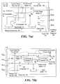
- FIGS. 7 ( a ) and 7 ( b )show an illustrative schematic diagram for an accessory power system and interface system
- FIG. 8shows an illustrative block diagram of an operator console accessory unit
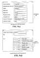
- FIGS. 9 ( a ), 9 ( b ), 9 ( c ) and 9 ( d )show software flowcharts and entry fields of an automatic identification system for the disclosed LAN telephone;
- FIG. 10shows a software flowchart of the disclosed control program change system
- FIG. 11shows a physical depiction of the disclosed external speakerphone accessory
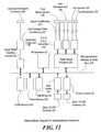
- FIG. 12shows a block diagram of the disclosed speakerphone accessory
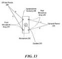
- FIG. 13illustrates the beam-steering technique of the disclosed speakerphone accessory.
- FIG. 1shows a physical representation of an embodiment of the disclosed LAN telephone.
- the embodiment of the LAN telephone shown in FIG. 1includes a base unit 6 containing electronics circuitry necessary to provide the functions associated with the base unit 6 as described herein.
- the base unit 6supports a handset 2 , an internal speaker 5 for speakerphone functions, and a status display 3 for displaying user status information.
- the base unit 6may be connected to a data switch via a LAN cable 1 , for example by way of a conventional data cable infrastructure, such as that shown in FIG. 3 .
- An accessory connectoris provided on each side of the base unit 6 , as illustrated by left accessory connector 4 . Using the accessory connectors, it is possible to add a variety of accessory devices, including an operator console 7 as shown in FIG. 1, and/or an external speakerphone.
- FIG. 5The internal circuitry of an illustrative embodiment of the base unit 6 is shown in FIG. 5 .
- the embodiment of the disclosed LAN telephone shown in FIG. 5is implemented as a microprocessor based system.
- a microprocessor 74is shown attached to a parallel microprocessor bus 76 , which provides an interface to various components via its address and data lines.
- the microprocessor 74may, for example, be a Reduced Instruction Set Computer (RISC) processor, using a 16 bit wide data bus.
- the bus 76is also connected to a Read Only Memory (ROM) 56 , Flash Memory 57 , and a Read And write Memory (RAM) 58 .
- ROMRead Only Memory
- RAMRead And write Memory
- the bus 76further connects to USB interface circuits 55 , as well as input latches 60 and output latches 62 .
- the bus 76additionally connects to a LAN Media Access Controller 64 , a text display 63 and a Digital Signal Processor (DSP) 75 .
- DSPDigital Signal Processor
- the microprocessor 74may use three types of memory to store such control software: ROM 56 , Flash 57 and RAM 58 .
- the ROM 56may be used to store the microprocessor's basic initialization program.
- the microprocessor 74first executes a portion of its control code that is stored in the ROM 56 .
- the control code program stored in the ROM 56causes the microprocessor 74 to initialize all hardware peripherals of the LAN telephone, such as the MAC 64 and the output latches 62 .
- the control code program stored in the ROM 56further performs a self-test of the LAN telephone.
- the self testincludes checking the microprocessor itself, testing the RAM 58 and performing a checksum verification of the contents of ROM 56 and the Flash memory 57 .
- the ROM 56also contains program code operable to load the Flash memory from the MAC 64 .
- One of the indicators 61for example a light emitting diode (LED), is placed on the bottom of the LAN telephone, near the LAN connector.
- This LED indicatoris attached to a flip-flop register that automatically resets itself on each power up, thus causing the LED indicator to turn on.
- the microprocessor 74finishes its self-test, it toggles the “set” line on the flip-flop register by activating a one bit port on the output latches 62 . This action causes the LED indicator to turn off. In this way, the LAN telephone's main electronics module can indicate if it is functioning properly.
- the control code instructions stored in the ROM 56may, in addition, also display an “OK” message in the text display 63 . However, in the event that the text display 63 malfunctions, the LED indicator will still operate.
- the microprocessor 74When the microprocessor 74 finishes executing the control program code stored in the ROM 56 , it then executes control program code stored in the flash memory 57 .
- the main body of the LAN telephone control program functionalityis stored in the flash memory 57 .
- Flash memory 57is advantageously capable of having its contents updated or replaced. Through use of this capability of the flash memory 57 , the LAN telephone can be loaded with new program code providing additional or modified functionality. Similarly, a fault or bug in the control program can be repaired, by storing a new program into the flash memory 57 . If no program code is loaded in the flash memory 57 , or if the program in the flash memory 57 does not yield a proper error check, then the microprocessor will enter an idle state. In this idle state, the microprocessor awaits a new control program to be downloaded into the LAN phone, for example from a LAN switch.
- the RAM memory 58is used for the storage of program variables and state information.
- the RAM 58may have part or all of its memory protected via a “battery backup”. In this way variable values can be maintained across a power failure.
- the disclosed LAN telephonemay communicate with other LAN telephones via the LAN to which it is attached.
- the LAN telephoneuses the LAN MAC 64 to send and receive packets of data in Ethernet format.
- the LAN MAC 64is connected to the LAN cable using a PHYsical interface (PHY) 65 .
- PHY 65provides level and impedance translation, as well as other signal conditioning needed to send packets over a twisted pair wire.
- the PHY 65is connected to the LAN Connector 67 .
- the LAN Connector 67may, for example, be a conventional “RJ” style connector (e.g. RJ-45).
- the PHY 65uses two twisted pair wires within the cable bundle attached to the LAN Connector 67 , one for transmit data and one for receive data.
- the disclosed LAN telephoneobtains its operating power from the LAN cable 1 shown in FIG. 1, through the LAN Connector 67 .
- This embodimentmakes use of another, normally unused wire pair in the cable bundle to receive power, for example from a LAN switch.
- the received poweris conditioned and voltage translated via the power circuit 66 .
- This power circuit 66is further described herein with reference to FIGS. 6 and 7.
- the LAN telephone base unit 6includes a number of user buttons, shown for purposes of illustration as key switches 59 in FIG. 5 .
- the key switches 59may be operated by a user, in order to dial calls, and/or to access various features of the LAN telephone.
- the states of the key switches 59are determined by the microprocessor 74 as it reads the contents of the input latches 60 .
- the input latches 60are connected to the key switches 59 . In this way, more key switches can be accommodated, for a given number of input latch ports.
- the microprocessor 74reads the key switches 59 periodically, for example, at times determined by an internal interrupt.
- the microprocessor 74rejects spurious key transitions, only accepting those that are active for at least a minimum time.
- LED indicators on the disclosed LAN telephonemay be used to display call status.
- the microprocessor 74may control the state of such indicators, as needed, via commands to the output latches 62 .
- the text display 63 in the embodiment of FIG. 5may, for example, be a two-line Liquid Crystal Display (LCD).
- the text display 63may receive power from a circuit card within the LAN telephone.
- the microprocessor 74writes messages to the text display 63 to provide assistance to the user.
- USBUniversal Serial Bus
- the microprocessor 74may send and receive messages and commands to accessories via this modified USB interface.
- the USB Controllers 55are connected to the left 53 and right 52 accessory connectors via a power conditioning circuit 54 .
- the DSP 75is an integrated processor that is optimized for manipulating analog signals that are translated into digital form.
- the DSP 75is connected to the bus 76 .
- the DSP 75includes an internal dual-port RAM, which is connected to a DSP core processor and to the bus 76 . In this way, the DSP 75 may be issued commands and its control program loaded by the microprocessor 74 , out of the flash memory 57 , over the bus 76 .
- the DSP 75also includes an internal ROM, which can contain a basic “Boot” program for the DSP.
- the DSP 75After initialization, the DSP 75 provides a message, via its dual-port memory, to the microprocessor 74 , indicating that the DSP 75 is ready to accept its control program.
- the control program of the DSP 75is loaded into DSP memory, by the microprocessor 74 , prior to the LAN telephone entering a “Ready” state. In the Ready state, the LAN telephone is ready to accept and place telephone calls.
- the DSP 75is further shown connected to the analog inputs and outputs via Analog to Digital (A to D) and Digital to Analog (D to A) converters 73 .
- the converters 73translate the analog, voltage-based signal into a digital signal.
- the A to D and D to A converters 73are combined into one package, providing two-way translation.
- the handset 2 (FIG. 1 ), and a headset (not shown),are connected to the base unit via the handset connector 71 and headset connector 70 shown in FIG. 5 .
- the internal speaker 69 and internal microphone 68 shown in FIG. 5are directly connected to the DSP 75 via a signal conditioning element 72 .
- the signal conditioning element 72also provides an interface to the handset connector 71 and the headset connectors 70 .
- the signal conditioning element 72provides signal limiting, gain or attenuation, filtering, and power, as needed.
- the LAN telephonereceives control messages from a switch or telephone server, via the LAN to which it is connected. These messages and associated responses are used to initiate telephony sessions. For example, when a call is in progress, speech audio is received by the microphone of the handset 2 , and conveyed through signal conditioning element 72 and converter 73 to the DSP 75 . The speech audio is thus sampled and converted into a stream of digital numbers (“samples”) by the A-D functionality of the converters 73 . Each such number represents the voltage of the received microphone speech signal. The DSP 75 then places these samples in its internal RAM and signals the microprocessor 74 when an appropriate number of samples are ready for processing.
- the microprocessor 74reads the samples, places them into a packet format consistent with a LAN protocol and the IP (Internet Protocol) protocol, and sends this resulting packet to the LAN switch, via the MAC 64 .
- the resulting packetmay, for example, be what is referred to as an “IP over Ethernet” format packet.
- the DSP 75may also employ a “compression” algorithm, whereby the number of speech signal samples conveyed to the switch may be reduced. In such an embodiment, as a result of the compression, the microprocessor 74 will have a smaller set of data items to transmit to the distant telephone.
- Various specific conventional compression algorithmsmay be employed in this regard.
- the effectiveness of a given compression algorithmis usually inversely proportional to the quality of the resulting speech, after it is “de-compressed” by the distant telephone.
- the microprocessor 74While the microprocessor 74 is accepting speech sample data from the DSP 75 and sending it to the distant telephone via the MAC 64 and LAN switch, it simultaneously must perform the receive function. That is, the microprocessor 74 simultaneously processes received data packets, from the distant telephone, via the LAN switch and the MAC 64 . These received packets contain voice data from the distant telephone. The microprocessor 74 accepts these packets, extracts the voice data contained therein, and then transfers the extracted voice data to the DSP 75 .
- the DSP 75then takes the voice samples, decompresses them if necessary, and provides them to the converter 73 , for output to the handset 2 through the handset connector 71 .
- the receive process and transmit process provided through the microprocessor 74must operate simultaneously, so that voice samples are accepted from and delivered to the A-to-D and D-to-A functions of the converters 73 on time.
- Normal, uncompressed telephony voiceuses a sample rate of 8 kilo-hertz.
- the DSP 75must receive one sample and output one sample every 125 microseconds, in order to support normal telephone speech.
- Packet contentionmay result when packets from other LAN users can be transmitted simultaneously with voice packets, potentially causing interference with the voice packets. Under such circumstances, voice packets may even be lost, causing an audible break in the received speech.
- voice packetsmay even be lost, causing an audible break in the received speech.
- the disclosed LAN telephoneincorporates a system for transmitting speech data packets such that they will not interfere with packets from other real-time devices on the network.
- the disclosed systemincludes what is referred to herein as “packet scheduling”, and the technology upon which it is based is referred to as “Time Based Routing” or “TBR.”
- packet schedulingthe technology upon which it is based is referred to as “Time Based Routing” or “TBR.”
- TBRTime Based Routing
- the LAN switchmaintains time synchronization with the LAN telephone via the transmission of a framing message referred to as a “heartbeat packet”.
- the heartbeat packetis used to “lock” the LAN telephone's internal clock to an internal clock of the switch. In this way all LAN telephones in the system (as well as other real-time devices) are able to maintain synchronization with one another.
- the LAN telephonescan operate in connection with schedules which define the reception and transmission of real-time packets.
- FIGS. 4 a - 4 dillustrate schedule assignment for two of the disclosed LAN telephones, which may also be referred to as “IP phones”, and which share the same circuit path.
- the disclosed scheduling systemis based on the occurrence of schedules. Schedules are expected time periods during which packet transmissions and/or receptions for one or more packet flows. Schedules occur independently at each switch within the network. A given schedule may apply to the transmit and receive functions of all ports within a switch, or to a subset of the transmit and/or receive functions of one or more ports within a switch. Accordingly, a given switch may operate based on a single schedule, or on multiple schedules Schedules may be repeated continuously. Alternatively, each schedule may be triggered explicitly in response to a trigger event, as further described below.
- FIG. 4 ( a )An illustrative schedule interval 40 is shown in FIG. 4 ( a ).
- packet flow offsetsdefine the beginnings of packets or packet groups associated with packet flows.
- Packet flowsdefine sets of packets associated with real-time applications, such as would be used to establish a telephone call or session. Accordingly, a packet flow associated with a telephone call or session may be identified by some set of packet header field values that are common to all packets within that packet flow.
- Packet flowsare typically unidirectional, and accordingly may be associated with either the transmit or receive function of a switch or telephone instrument.
- a packet flow offsetis associated with a transmit function
- that packet flow offsetdefines a time within a schedule interval at which transmission of one or more packets for the associated packet flow may be initiated.
- a packet flow offsetis associated with a receive function
- that packet flow offsetdefines a point in time within a schedule interval at which reception of one or more packets for the associated packet flow may be expected.
- a packet flow scheduleFor a given packet flow, different packet flow offsets are established for each switch along the path between a first telephone instrument and a second telephone instrument.
- the set of offset values associated with a packet flow for all switches along such a pathdefines a schedule for that packet flow (also referred to as a “packet flow schedule”).
- a packet flow schedulemay also include a schedule interval duration and packet length.
- a time period within the schedule interval associated with a given packet flow scheduleis referred to as the packet flow schedule period.
- the beginning and/or the end of the schedule interval 40is defined by the heartbeat packet 41 .
- the LAN switchmay transmit a heartbeat 41 to all of its ports.
- the heartbeat packet 41is timed to conclude just as the next schedule interval commences.
- the heartbeat packet 41when received, allows the disclosed LAN telephone to synchronize its internal clock and schedule interval with the LAN switch.
- the LAN telephoneWhen the LAN telephone establishes a telephone session, it obtains schedule information from a call agent, which is implemented as software executing on a server system, for example attached to or co-existing with the LAN switch.
- the call agentis operable to communicate with the switch and negotiate schedules for real-time packet traffic.
- the call agentAfter a schedule is established, the call agent sends the relevant schedule information to the LAN telephone.
- the LAN telephoneis then permitted to send telephone voice packets, one or more together in each burst, at regular intervals. These packets are transmitted in accordance with the schedule information given to the LAN Telephone by the call agent. By transmitting the packets only in accordance with the schedule information provided by the call agent, contention between LAN telephones is eliminated. The call agent thus assigns different schedules for each LAN telephone session traversing a common circuit path.
- FIG. 4 ( b )shows a schedule assignment for a first LAN telephone session with respect to a schedule interval within a first LAN telephone.
- the call agenthas assigned a first packet flow offset for the first LAN telephone that defines the voice packet data transmission 42 , as well as a second packet flow offset defining the voice packet data transmission 43 .
- the voice data packets from a first LAN telephone “A”are actually transmitted in accordance with the first packet flow offset and second packet flow offset, as shown by the voice packet(s) data “A 1 ” 42 and “A 2 ” 43 in FIG. 4 ( b ).
- the first LAN telephone “A”is transmitting telephone voice data in an uncompressed format, that is, at 8 thousand samples per second.
- FIG. 4 ( c )a schedule interval for transmission of data is shown for a second LAN Telephone “B”.
- the call agenthas assigned LAN telephone “B” different packet flow offsets within the schedule interval from those assigned to LAN telephone “A”. It is not necessary for the LAN switch, or call agent to always assign different packet flow offsets to different LAN telephones. This is only necessary when multiple LAN telephones require a session which must traverse a common circuit.
- LAN telephones “A” and “B”both communicate with the WAN link. Thus, different packet flow offsets are needed.
- the call agenthas assigned LAN Telephone “B” packet flow offsets resulting in transmission of voice packet(s) data B 1 44 and voice packet(s) data B 2 . Because schedule intervals are defined on a per port basis with respect to the LAN switch, and the LAN telephone “A” and LAN telephone “B” are connected to the LAN switch via different ports, LAN telephone “A” 's packet data is not seen on LAN Telephone “B”'s schedule interval, and vice versa.
- FIG. 4 ( d )shows the transmission schedule interval for the LAN switch port connected to the WAN interface. Because the sessions for LAN telephone “A” and the LAN telephone “B” pass through the WAN interface, the LAN switch must provide voice data from both LAN telephone “A” and LAN telephone “B” to the WAN Server. Because LAN telephone “A” and LAN telephone “B” have individually assigned packet flow offsets that do not conflict, there is never a situation when the voice packet traffic from one LAN telephone interferes with that from another LAN telephone.
- the handling of LAN trafficis absolute. This means that for a given packet flow offset within a given schedule interval, the switch can “set” the connection. All other traffic destined for a port, at the time of the packet flow offset, must be queued and sent after the scheduled packet flow has concluded.
- the switchWhen the predetermined amount of data that is to be transmitted at a given packet flow offset has been completely transmitted, if there is no other scheduled data to be transmitted, other unscheduled traffic may be transmitted. For example, if the amount of data to be transmitted at a given packet flow offset is defined in terms of a number of packets, then the switch will count such packets as they are transmitted. When the last packet has traversed the switch, the LAN switch opens the relevant circuit for any other packet traffic that may be queued for the particular destination port. The switch may also allow new packets to enter the switch and be routed in the normal fashion, if such actions would not interfere with other scheduled traffic.
- the disclosed LAN telephonereceives it power from the LAN cabling to which it is attached.
- LAN cablestypically have four, individual twisted pair wires per station cable. One pair is used for transmit data, received by the LAN telephone from the LAN switch. Another pair is used for receive data, transmitted from the LAN telephone to the LAN Switch. Two other pairs are often unused or reserved for future expansion.
- the unused pairsare doubled up, and used to send power to the LAN telephone instrument, from the switch, or from a power source co-located with the switch. In this way, the disclosed LAN telephone does not need to have an additional power supply, with inconvenient cords.
- multiple LAN telephonesmay be operated by a single supply, which can have battery-backup and thus provide power in the event of a power failure.
- FIG. 6An illustrative embodiment of the disclosed LAN telephone power supply system is shown in FIG. 6 .
- the data signals and powercome into the telephone circuit card 81 via the LAN Connector 80 .
- twisted pairs 1 and 2are used for data, leaving pairs 3 and 4 free for power.
- the poweris delivered as 48 VDC.
- the delivered powercould be other voltages, or even AC.
- 48 VDCis most convenient.
- Typical LAN cableis 24 gauge (AWG) which has a limited current handling capability.
- such conventional cablecould deliver a maximum of 24 watts at 500 milliamps of current. Since the power cable is doubled up, it is actually possible to double the power delivered, to 48 Watts. This is more than enough to operate the LAN telephone and attached accessories.
- the powerAs the power enters the LAN telephone circuit card 81 , it connects first to a surge arrestor 82 . This device, or combination of devices, is used to prevent stray surges from damaging the LAN telephone or propagating to the accessories. The power is then buffered via a low-pass filter network 83 . The network 83 is commonly used to filter out any signals, such as data signals, which may have coupled to the power lines. Finally, the power is connected to a 48 VDC to 5 VDC power supply 84 , of the DC—DC converter type. The power supply 84 is used to provide the proper supply voltages to the LAN telephone. These voltages include, for example, 5 VDC and 3.3 VDC, and may include others as well. The DC—DC converter 84 is a switching device, which may transfer nearly all of the input power for use by the LAN Telephone. Further in an illustrative embodiment, the input 48 VDC may also be provided to the accessory power system, after suppression of any surges.
- the disclosed LAN telephoneunlike most other telephones, is capable of supporting a variety of accessories. These accessories include an operator console and an external speakerphone unit.
- the accessory systemis designed for future expansion.
- USBUniversal Serial Bus
- USBis a relatively simple, fast (1.5 to 480 megabits per second), and standardized bus used for computer devices.
- the disclosed LAN telephoneuses a modified USB for interconnection of telephone accessories to the disclosed LAN telephone.
- One difficulty with the existing USBis that it has only a limited capability to provide power to a connected device. As it is generally known, USB has two wires in the cable, which supply 5 VDC. Current is limited to 0.5 Amp. Additionally, any given device can only use 0.1 Amp.
- USBallows devices to be chained, so all chained devices must share the same power. This means that the maximum power available is 2.5 Watts, with 0.5 Watt for each device. This is too little for many potential devices. For instance, a typical LED indicator uses 20 milli-Amps. Accordingly, an accessory using the existing USB could have five LEDs, and nothing else. The operator console 7 of FIG. 1, could easily have 20 or even 100 such LEDs, and require other power as well. Moreover, a speaker phone unit could easily exceed the 2.5 Watt maximum, even if it used all of the USB power. For this reason the disclosed LAN telephone provides a unique, dual-voltage accessory power system. The disclosed dual-voltage accessory power system allows the LAN telephone to alternatively supply power at 48 VDC, instead of 5 VDC, thus increasing the power consumption by a factor of 10.
- FIG. 7 ( a ) and FIG. 7 ( b )An embodiment of the disclosed LAN telephone accessory power system is depicted in FIG. 7 ( a ) and FIG. 7 ( b ).
- FIG. 7 ( a )is shown a source power system.
- the source power system of FIG. 7 ( a )is used to provide power to the accessory.
- FIG. 7 ( b )depicts an illustrative embodiment of the accessory internal power system.
- the accessory internal power systemreceives and converts the power from the source power system, which, for example, is contained within the LAN telephone.
- the source poweris provided by the base unit 6 to the accessory unit via an accessory connector 104 , which is shown for purposes of illustration as a USB “A” connector.
- the connector 104includes four wires.
- Two wiresare used for power, specifically power pin 1 100 and ground pin 4 103 .
- Two other pinsare used for data transfers, specifically pin 2 101 and pin 3 102 .
- Poweris supplied on pin 1 100 of the connector 104 at either 5 VDC or at 48 VDC.
- the selection of supply voltageis made by the base unit microprocessor 74 .
- the microprocessor 74sets an appropriate bit in the output latch 96 to select the proper power supply voltage.
- the necessary power switch or switchesmay be implemented as a Double Pole Single Throw or a Double Pole Double Throw with MOSFET (Metal Oxide Semiconductor Field Effect Transistor).
- default power settingis normally 5 VDC.
- the accessoryis queried by the base unit microprocessor 74 , via the USB interface 55 , to determine if the accessory uses 48 VDC. Such a query may, for example, be provided to the accessory over the data lines of the modified USB interface. A 48 VDC-capable accessory will respond to such a query in the affirmative. If the microprocessor 74 determines that the accessory uses 48 VDC, then the microprocessor 74 switches the voltage to 48 VDC. The 48 VDC is available from the station input power 86 . The 5 VDC power is available from the base unit's power converter 84 .
- the base unit microprocessor 74monitors the power usage by accessories connected to the base unit. It accomplishes this via a monitoring system.
- Low value, current sense resistors 98are connected in series with the 48 VDC and the 5 VDC power lines. A voltage differential is formed across the resistors 98 , as current passes through. When an accessory is connected, a minimum current is passed, causing a small but measureable voltage to be present at the input of the HV and LV comparators 92 and 93 .
- the purpose of this circuitis to determine if the USB device is connected. In the illustrative embodiment of FIG. 7 ( a ), the current threshold is 10 milli-amps.
- the output of the two comparatorsis connected to the input buffer 94 .
- the microprocessor 74reads the input buffer 94 periodically, to determine if the accessory device is still connected. If the microprocessor 74 determines that the accessory device has been disconnected, then the microprocessor automatically resets the power switch 97 to 5 VDC operation. This action will prevent damage to a non-48 VDC capable USB device. Two comparators and two current sense resistors are required because the minimum currents will be different through each.
- FIG. 7 ( b )An illustrative embodiment of the disclosed accessory power system is shown in FIG. 7 ( b ).
- the system of FIG. 7 ( b )allows the accessory to automatically switch from the low-power to high-power modes.
- Powerenters the accessory via a standard USB “B” connector 105 .
- the plus 5 VDCis present on pin 1 118
- the Power ground returnis on Pin 4 109 .
- the current limit 110 and voltage level 108 resistorsare connected across the power 118 and ground 109 lines.
- the voltage developed across the voltage level resistor 108is connected to the 48 VDC comparator 111 .
- the comparator 111senses that the voltage has exceeded the 5.5 VDC limit for USB, then it provides a control signal to the power select switch 113 and the 48 VDC to 5V DC DC—DC Converter 112 .
- Accessory Poweris 3.3 VDC, normally provided by the 5 VDC to 3.3 VDC Power Converter 114 .
- the converter 114can also be implemented as a shunt converter, if the power drain is low. This converter 114 derives its input power from either the input power bus 118 or the 48 VDC to 5 VDC converter 112 .
- the power select switch 113may be implemented as a Double Pole Single Throw (DPST) switch, similar the power switch in the source power system 97 .
- DPSTDouble Pole Single Throw
- the 5 VDC to 3.3 VDC Converter 114receives its power from the Input Power Bus 118 . If the power voltage is higher than 5 VDC, then the converter 114 receives its input power from the 48 VDC to 5 VDC Power Converter 112 .
- the accessory microprocessor 124monitors the input buffer 119 to determine if 48 VDC is available. If 48 VDC is present, then the accessory microprocessor 124 can enable functions that require higher power. Power is provided to the accessory downstream power circuit.
- the accessory downstream power circuitincludes 48 VDC, if available or 5 VDC. The accessory downstream power circuit can then provide power to another accessory, “daisy-chained” from the first accessory.
- FIG. 8An embodiment of the LAN Telephone Operator Console is illustrated in FIG. 8 .
- the console of FIG. 8includes, for example, 100 small buttons and 100 LED indicators.
- the console of FIG. 8allows the user (usually an operator) to monitor the status of up to 100 extensions.
- a smaller, alternative accessory console embodimentmay, for example, support up to 20 extensions. LEDs are individually associated with each button and each extension. An “on” LED indicates that the line is busy. The operator may transfer a call directly by pressing the button associated with the extension, while a current call is connected. The calling party will then be connected to the extension.
- the console accessory of FIG. 8is an example of a device that generally needs more power than 0.5 Watts.
- FIG. 8shows an internal block diagram of an operator console accessory.
- the console of FIG. 8is controlled via a microprocessor 124 .
- the microprocessor 124is connected to a data and address bus 134 , which is used to control and access all of the keys and switches.
- the microprocessor 124connects with the USB Interfaces 123 .
- One of the USB Interfaces 123is used for “Upstream” communications, to the base unit, and another one is used for “Downstream” communications, to additional accessories.
- Both USB interfaceshave power conditioning circuits 122 , whose operation has been described above in connection with FIG. 7 ( b ).
- the circuits 122allow the accessory to derive additional power over the USB interface, with no additional cables or connectors.
- the microprocessor 124also connects to output latches 128 and input latches 129 to enable the unit to read the status of all the buttons.
- the key switch matrix 130is read by enabling rows of switches, via output latches 126 , and reading the rows with the input latches 129 .
- the indicators 131are operated by setting the corresponding bits in the output latches 132 . For the operator console, there is one bit for each LED indicator.
- An optional text display 133is also connected to the data and address Bus 134 . The text display 133 is used to present operator-specific messages to an operator.
- FIG. 8is further illustrative of other possible accessory designs.
- FIG. 9illustrates the disclosed LAN telephone's system for automatic registration with a LAN switch and a call agent.
- the disclosed systemallows the LAN telephone to be moved from one LAN circuit cable or switch port to another, without changing the switch configuration.
- the disclosed systemworks by recognizing the specific LAN telephone's serial number, using that serial number to link to a database, and then “learning” the path to the LAN telephone. This process is performed in the call agent and in the LAN Telephone itself.
- FIG. 9 ( a )is shown the set-up process to ready the LAN Telephone for regular use.
- the process shown in FIG. 9 ( a )may be initiated at any time by a “hard” reset of the device.
- FIG. 9 ( a )shows a software flow-chart of the telephone configuration procedure.
- the telephoneenters the procedure via a hard reset 140 .
- the telephoneexecutes an initialization and self-test program at step 141 .
- all of the latches and interfaces of the deviceare reset and properly configured.
- the microprocessor 74 , and memories 56 , 57 and 58are tested, along with the DSP 75 .
- the LAN telephonewill display the current revision level of the control program, stored in flash memory 57 , along with an “OK” message, as shown in the power init display 143 of FIG. 9 ( a ). If the program executed at step 141 does not complete successfully, then the display will show “Fail” message, along with some indication as to the nature of the failure, as shown by the fail display 146 of FIG. 9 ( a ). A fail determination at step 145 will also cause the telephone to enter an idle state 144 .
- DHCPDynamic Host Configuration Protocol
- DHCPDynamic Host Configuration Protocol
- An input of “Y”will cause the telephone to prompt the user for DHCP information (not shown).
- An “N” responsewill cause the telephone to prompt the user to enter the assigned IP number for the LAN telephone at step 150 , and as illustrated in the instrument IP entry display 151 .
- the telephonewill prompt the user for the Server IP number, as illustrated by the server IP entry display 153 .
- This numberis the IP address of the call agent server, to which the LAN telephone will direct and accept call requests.
- the server IP numberis entered, then the “Hard Initialization” phase is ended at step 154 .
- FIG. 9 ( b )shows the series of steps, and associated displays, by which the disclosed LAN telephone identifies itself to a call agent.
- the process of FIG. 9 ( b )is entered either via the successful completion of a hard init 160 , or via a power-on reset 161 .
- a power-on reset 161the LAN telephone has just been connected to the LAN network, or the system power has just been restored, after a complete power failure.
- the power-on reset 161is activated.
- the first stepis to complete an initialization and self-test at step 162 , which is essentially the same as performed at step 141 of FIG. 9 ( a ) for the hard reset 140 .
- An initial displayis provided at step 163 , as illustrated by init display 164 . This has the same result as before. If the LAN telephone does not fail initialization and self test, as determined at step 166 , then the network registration process begins. Otherwise, if the LAN telephone does fail initialization and self test, then an idle state 165 is entered.
- the LAN telephonechecks to see if it is configured for DHCP operation at step 168 .
- DHCPDynamic Host Configuration Protocol
- IPInternet Protocol
- a logon messageis sent to the call agent at step 170 , at the call agent's assigned IP address.
- the telephonedetermines at step 174 whether a positive response is received from the call agent. If the telephone does not receive a positive response, then it waits a delay of random length at step 169 , and returns to step 170 . This process will repeat for a limited number of times, in this case, ten times.
- the telephonedetermines whether the logon has been attempted the maximum number of times permitted before a failure is reported. If the logon attempt is unsuccessful then the telephone displays a logon failure display 175 and enters an idle state. If the logon attempt succeeds, then the telephone enters the “Ready” state at step 176 , and displays the normal ready display 177 , which typically contains the date and time. The telephone is now ready to make and receive calls.
- the call agent programmaintains a database, which contains a number of user records, each of which is keyed to the serial number of a LAN telephone.
- One of the user records in the databaseis keyed to the serial number of the illustrative LAN telephone whose operation is described in connection with the steps shown in FIG. 9 ( b ).
- the serial number of the LAN telephoneis included in the request, and allows the call agent to determine a user name that is associated with the serial number in the database, accordingly identify the telephone user and call parameters.
- Such call parametersmay, for example, include an associated telephone number, user name, Ethernet MAC (Media Access Control) address, serial number, and/or IP (Internet Protocol) address.
- an entry field programautomatically assists a system administrator in configuring the LAN telephone.
- the administratorruns an initialization program.
- the contents of an administrator record from the database, for that telephoneis displayed on the screen.
- An illustrative administrator record 180is shown in FIG. 9 ( c ).
- the contents of database fields for name and extension numbercan then be modified or reentered. Subsequently, the new or modified record, for that telephone instrument, is ready for use.
- a specific LAN telephone's physical locationmay be traced, to the office and wall jack, via a location record, such as the illustrative location record 181 of FIG. 9 ( d ).
- the Location Record 181displays the location of every LAN telephone, within a network served by a call agent.
- the disclosed LAN Telephonemay include the ability to accept a new control program. This capability is import to allow for future upgrades to the telephone instrument's functions. The upgrade is accomplished by sending a new object program code image to each telephone instrument. Such a change in program code must be accomplished with a trusted procedure. Otherwise, the telephone could loose its ability to receive new code, and could further be rendered inoperable.
- the disclosed LAN telephonemay accomplish such a code change by segregating the code into three pieces. For example, a first piece including modules referred to as Init and Com Load may be stored in the ROM 56 . These modules are highly tested, designed to support the hardware initialization, and to reliably down load a new control program a call agent.
- the actual control program for the LAN telephonemay be temporarily stored, one segment at a time, within the RAM 58 , as it is received. Each segment is then loaded into the Flash Memory 57 . The control program is then entered, after the initialization sequence is completed, as described above in connection with FIG. 9 ( b ).
- the Init and Com Load modulesin ROM 56 , and placing only the control program in Flash Memory 57 , no failure of the program load process can prevent the LAN Telephone from retrying the program load. In this way, no failure will permanently disable the LAN Telephone.
- FIG. 10A flow chart of steps performed by an illustrative embodiment of the disclosed LAN Telephone during a control program update is illustrated in FIG. 10 .
- the process of FIG. 10is entered from a ready state 190 .
- the processis initiated by receipt of an update command at step 191 .
- the update commandis sent by the call agent, which may reside on a network telephony server.
- the control program object code to be provided to the LAN telephone during the updatemay be stored on the network telephony server.
- the operatorWhen an operator desires to update the LAN telephones on the network, the operator initiates an update command from a network administration program.
- the call agentthen sends an update command at step 191 to each LAN telephone within the network in turn.
- the call agentmay complete the update process for each individual LAN telephone before moving on to the next LAN telephone. In this way all of the LAN telephones in the network can be updated, automatically.
- the update processcan be scheduled, so that the update is performed in an off hour.
- the LAN Telephonethen authenticates the update command at step 192 .
- the LAN telephonemay use an encrypted signature system to provide authentication of both the update command and subsequent data messages. Such authentication may be performed using a conventional authentication technique.
- the LAN Telephonesend a response 192 indicating its readiness to receive the new code image.
- the call agentin conjunction with the network administration program, then begins transmitting the update image, which is received at step 193 .
- the entire load processis conducted under the control of control code located in the LAN telephone ROM 56 .
- the loadmay be performed using IP TCP packet checking, and with a final, complete error check, using a standard CRC (Cyclic Redundancy Check) error checking system at step 195 .
- CRCCyclic Redundancy Check
- the new control programwill complete its load of the flash memory 57 at step 197 . Otherwise, an update fail message is transmitted at step 194 .
- the LAN telephonereturns an update acknowledge message at step 198 , and returns to the ready state at step 200 . As the LAN telephone enters the Ready state at step 200 , it will be using the new control program.
- the system administratorlogs the updated LAN Telephone as including its new control program revision, and then moves on to updating the next LAN Telephone scheduled for updating.
- the LAN telephonemay then retry the update process. Successful completion of the update process will result in an “OK” revision message in the instrument display, as shown by the update OK display 199 . While the LAN Telephone is undergoing an update, the update program display 201 is displayed on the instrument's status display 3 .
- the disclosed LAN Telephoneis also capable of supporting a variety of audio accessories. Such accessories may be connected to the LAN Telephone base unit 6 via the enhanced USB system, as disclosed herein.
- One useful audio accessoryis an external speakerphone.
- Many office telephonesfeature a “hands-free” built-in speakerphone.
- the disclosed LAN Telephonemay include such a feature as well.
- the effectiveness of built-in speakerphonesmay be limited.
- a user's telephoneis located behind, or to the side of their work surface. As a result, the ability of an internal speakerphone to pickup voices from the other side of the desk is limited.
- the external speakerphone described hereinsolves this problem.
- FIG. 11An illustrative embodiment of the disclosed external speakerphone 210 is shown in FIG. 11 .
- the speakerphone 210is shown as a pod connected to the base unit 6 (FIG. 1 ), via an accessory cable 217 , through an accessory connector 4 (FIG. 1 ).
- the external speakerphone 210can derive all of its power, audio, and control signals from the LAN Telephone base unit 6 (FIG. 1 ).
- the external speakerphone 210may be placed on the main portion of a user's desk, even between the user and any visitors that may be sitting on the other side of the user's desk.
- the external speakerphone 210Through its connection to the LAN Telephone, the external speakerphone 210 is able to operate in connection with any call that is active on the LAN Telephone.
- the external speakerphone 210includes two microphone arrays 211 and 214 , located on each side of the pod.
- the microphone arrays 211 and 214are used to receive voice audio from the primary telephone user, as well as from visitors to the primary telephone user's office.
- the microphone arrays 211 and 214as well as the top microphones 212 , enable to the LAN Telephone to discriminate and reject voices and noise from other locations in the office.
- the external speakerphone 210also includes a speaker 212 , which is used to output voice audio received from the distant party of the telephone connection.
- Also provided in the speakerphone 210are a mute button 213 , mute indicator 215 , on-off button 218 , and on-off indicator 219 , which aid in operating the device.
- FIG. 12An internal block diagram of an illustrative embodiment of the external speakerphone 210 is shown in FIG. 12 .
- the system of FIG. 12is shown including a microprocessor 232 , which controls an address and data bus 238 . Attached to the microprocessor 232 , via the bus 238 , are a number of serial “USB” interface circuits 223 .
- the circuit(s) 223is used to communicate digital audio along with command and status information to the microprocessor 232 .
- two or more USB interfacesmay be employed, for the attachment of other accessories.
- the microprocessor 232also makes use of ROM 224 , flash memory 225 , and RAM 226 .
- initialization and update routinesmay be stored in ROM 224
- the control program for the microprocessor and DSP 231may be stored in the flash memory 225
- the variables and buffersmay be stored in the RAM 226 .
- the microprocessor 232also controls the indicators 230 via output latches 229 , and receives input from buttons 227 via the input latch 228 .
- the microprocessor 232controls the DSP 231 via a dual-port RAM that is internal to the DSP 231 . In this way, the microprocessor 232 is able to load the DSP 231 prior to the beginning of operation.
- the DSP 231provides the interface for the microphones 235 , 236 , and 238 , as well as to the speaker 237 .
- Analog to Digital (A to D) and Digital to Analog (D to A) converters 233provide the transition between the buffered analog signals and the digital samples of those signals needed by the DSP 231 .
- the signal conditioners 234adapt the analog signals to and from the transducers 235 , 236 and 238 , in order to provide levels appropriate for the converters 233 .
- the DSP 231executes a program that performs acoustic echo cancellation, as needed by the telephone network.
- the DSP 231supports audio input and output.
- the DSP 231performs two mathematical functions. First, the DSP 231 performs a directional algorithm, referred to as “beam-steering”, for noise reduction and isolation, which operates to suppress any “off-axis” acoustic signals. Second, the DSP 231 performs a subtraction of received audio.
- the received audio that is subtractedconsists of the audio received by the accessory that is output of the speakers of the accessory.
- the received audiois subtracted from the input signal obtained from the microphones 235 , 236 and 238 .
- the object of this acoustic echo canceling algorithmis to eliminate acoustic coupling, coming through the air from the speaker, from the audio signal that is transmitted to the distant end.
- FIG. 13illustrates the disclosed technique, which operates to accentuate audio within the audio signal received through the various microphones of the device that is received from predetermined “on-axis” sources.
- the disclosed technique for suppressing off-axis audio signals received from the microphones of the devicefurther operates to assist in beam-nulling with respect to attenuating the audio signal output from the speaker of the device, based on the directionality of the output of the speaker.
- the digital sample signalsare processed by the DSP 231 such that the delays between the two paths to the microphone arrays are used to subtract out signals that originate from off-axis sources. This is the case with paths “a” and “b” from the off-axis person 240 in FIG. 12 . Such a delay does not exist between paths “c” and “d” from the centered person 244 .
- the delays for paths “a” and “b”may, for example, be in the range of fractions of milliseconds in length.
- the top microphone 242can also be used to help center the “beam” of greatest microphone sensitivity, so that the height of the audio sources is also considered. In this way, the top microphone 242 can be used to suppress audio signals that are not centered around a predetermined source height. In this way, two zones of maximum sensitivity are centered on either side of the speakerphone accessory 246 . As further shown in FIG. 13, off-axis voice signals may be detected by either of the front microphone array 241 or the rear microphone array 245 . Audio components determined to be “on-axis” may further be added to the received audio signal in order to emphasize audio from on-axis sources. Also in FIG. 13, a speaker 243 is shown for outputting audio signals from the speakerphone 246 .
- the subtraction of the audio signal output through the speakers from the input audio signal received through the various microphones of the speakerphone accessorymay be performed via an algorithm that includes an adaptation aspect which factors in the physical layout of the room or operating environment in which the speakerphone accessory located.
- Such an adaptation processmay operate to output a known signal in order to determine all necessary parameters related to the physical characteristics of the room or other operating environment.
- This audio adaptationmay, for example, include dividing up the received audio from the distant phone into frequency bands and then each octave is processed separately. The objective is to select a subtraction factor that minimizes the presence of known input audio in the transmitted signal.
- Conventional algorithms of this typeare well known, for example making use of Fourier transforms to characterize the office and user acoustic environment.
- the disclosed speakerphone accessoryWhile the illustrative embodiments of the disclosed speakerphone accessory shown in FIGS. 11 and 13 have two opposing sides at which users are expected to be positioned, the disclosed speakerphone accessory is not limited to such a configuration. Accordingly, those skilled in the art will recognize that the beam-nulling and beam-steering aspects of the disclosed system may be applied to one or more sides of a speakerphone accessory, and that the speakerphone accessory itself may be embodied in a variety of specific shapes.
Landscapes
- Engineering & Computer Science (AREA)
- Signal Processing (AREA)
- Computer Networks & Wireless Communication (AREA)
- Multimedia (AREA)
- Business, Economics & Management (AREA)
- General Business, Economics & Management (AREA)
- Small-Scale Networks (AREA)
- Telephonic Communication Services (AREA)
Abstract
Description
Claims (21)
Priority Applications (1)
| Application Number | Priority Date | Filing Date | Title |
|---|---|---|---|
| US09/780,685US6556564B2 (en) | 2000-02-08 | 2001-02-08 | Scheduled internet protocol telephone instrument system |
Applications Claiming Priority (2)
| Application Number | Priority Date | Filing Date | Title |
|---|---|---|---|
| US18109900P | 2000-02-08 | 2000-02-08 | |
| US09/780,685US6556564B2 (en) | 2000-02-08 | 2001-02-08 | Scheduled internet protocol telephone instrument system |
Publications (2)
| Publication Number | Publication Date |
|---|---|
| US20010033565A1 US20010033565A1 (en) | 2001-10-25 |
| US6556564B2true US6556564B2 (en) | 2003-04-29 |
Family
ID=22662898
Family Applications (2)
| Application Number | Title | Priority Date | Filing Date |
|---|---|---|---|
| US09/780,685Expired - LifetimeUS6556564B2 (en) | 2000-02-08 | 2001-02-08 | Scheduled internet protocol telephone instrument system |
| US09/779,328AbandonedUS20010033649A1 (en) | 2000-02-08 | 2001-02-08 | Speakerphone accessory for a telephone instrument |
Family Applications After (1)
| Application Number | Title | Priority Date | Filing Date |
|---|---|---|---|
| US09/779,328AbandonedUS20010033649A1 (en) | 2000-02-08 | 2001-02-08 | Speakerphone accessory for a telephone instrument |
Country Status (2)
| Country | Link |
|---|---|
| US (2) | US6556564B2 (en) |
| WO (2) | WO2001060029A1 (en) |
Cited By (23)
| Publication number | Priority date | Publication date | Assignee | Title |
|---|---|---|---|---|
| US20030146765A1 (en)* | 2002-02-01 | 2003-08-07 | Powerdsine Ltd. | Detecting network power connection status using AC signals |
| US20030189922A1 (en)* | 1998-08-19 | 2003-10-09 | Howe Wayne R. | Layer one switching in a packet, cell, or frame-based network |
| US20050058083A1 (en)* | 2003-09-17 | 2005-03-17 | Rivulet Communications, Inc. | Empirical scheduling of network packets using coarse and fine testing periods |
| US20050086362A1 (en)* | 2003-09-17 | 2005-04-21 | Rogers Steven A. | Empirical scheduling of network packets |
| US20050094642A1 (en)* | 2003-10-31 | 2005-05-05 | Rogers Steven A. | Endpoint packet scheduling system |
| US20050111357A1 (en)* | 2003-11-25 | 2005-05-26 | Rogers Steven A. | Internet endpoint system |
| US20050129069A1 (en)* | 2003-03-13 | 2005-06-16 | Yehuda Binder | Private telephone network connected to more than one public network |
| US6912206B1 (en)* | 2000-04-07 | 2005-06-28 | 3Com Corporation | Discovery of phones on a network, such as a LAN |
| US20050190770A1 (en)* | 2004-02-27 | 2005-09-01 | Iraj Saniee | Method of burst scheduling in a communication network |
| US20050254494A1 (en)* | 2000-09-21 | 2005-11-17 | Serconet, Ltd. | Telephone communication system and method over local area network wiring |
| US20060056444A1 (en)* | 1998-07-28 | 2006-03-16 | Serconet, Ltd | Local area network of serial intelligent cells |
| US20060077981A1 (en)* | 2004-10-13 | 2006-04-13 | Rivulet Communications, Inc. | Network connection device |
| US7054127B1 (en) | 2003-06-18 | 2006-05-30 | Cisco Technology, Inc. | Methods and apparatus to protect against voltage surges |
| US20060209847A1 (en)* | 1999-07-07 | 2006-09-21 | Serconet, Ltd. | Local area network for distributing data communication, sensing and control signals |
| US20070071026A1 (en)* | 2005-09-23 | 2007-03-29 | Rivulet Communications, Inc. | Compressed video packet scheduling system |
| US7274688B2 (en) | 2000-04-18 | 2007-09-25 | Serconet Ltd. | Telephone communication system over a single telephone line |
| US7436842B2 (en) | 2001-10-11 | 2008-10-14 | Serconet Ltd. | Outlet with analog signal adapter, a method for use thereof and a network using said outlet |
| US7522714B2 (en) | 2000-03-20 | 2009-04-21 | Serconet Ltd. | Telephone outlet for implementing a local area network over telephone lines and a local area network using such outlets |
| US7522615B2 (en) | 2002-11-13 | 2009-04-21 | Serconet, Ltd. | Addressable outlet, and a network using same |
| US7542554B2 (en) | 2001-07-05 | 2009-06-02 | Serconet, Ltd | Telephone outlet with packet telephony adapter, and a network using same |
| US7873058B2 (en) | 2004-11-08 | 2011-01-18 | Mosaid Technologies Incorporated | Outlet with analog signal adapter, a method for use thereof and a network using said outlet |
| US7936745B1 (en)* | 2006-06-23 | 2011-05-03 | Shoretel, Inc. | Multiple extension and line appearance for IP telephony |
| US10986164B2 (en) | 2004-01-13 | 2021-04-20 | May Patents Ltd. | Information device |
Families Citing this family (16)
| Publication number | Priority date | Publication date | Assignee | Title |
|---|---|---|---|---|
| JP2002271329A (en)* | 2001-03-08 | 2002-09-20 | Nec Corp | System data sharing management system in lan telephone system |
| US20030100350A1 (en)* | 2001-11-27 | 2003-05-29 | Kevin Dotzler | Speakerphone mute indicator |
| TWI220616B (en)* | 2002-08-19 | 2004-08-21 | Heng-Jian Chen | Digital private network composed of PBX/KTS and signal transmission method thereof |
| US7536560B2 (en)* | 2003-04-18 | 2009-05-19 | Via Technologies, Inc. | Microprocessor apparatus and method for providing configurable cryptographic key size |
| US7697827B2 (en) | 2005-10-17 | 2010-04-13 | Konicek Jeffrey C | User-friendlier interfaces for a camera |
| US8135143B2 (en)* | 2005-11-15 | 2012-03-13 | Yamaha Corporation | Remote conference apparatus and sound emitting/collecting apparatus |
| US20070274074A1 (en)* | 2006-02-01 | 2007-11-29 | Smires Daniel T | Method and apparatus for communicating a status of a device in a packet-based communication network |
| JP4816221B2 (en)* | 2006-04-21 | 2011-11-16 | ヤマハ株式会社 | Sound pickup device and audio conference device |
| EP2090895B1 (en)* | 2006-11-09 | 2011-01-05 | Panasonic Corporation | Sound source position detector |
| US20080192304A1 (en)* | 2007-02-14 | 2008-08-14 | Robertus Hartono | Method And System For Facsimile Transmission |
| US9032079B2 (en) | 2007-06-26 | 2015-05-12 | Microsoft Technology Licensing, Llc | Management and diagnosis of telephonic devices |
| WO2009019748A1 (en)* | 2007-08-03 | 2009-02-12 | Fujitsu Limited | Sound receiving device, directional characteristic deriving method, directional characteristic deriving apparatus and computer program |
| US20090097473A1 (en)* | 2007-10-11 | 2009-04-16 | Inventec Multimedia & Telecom Corporation | Functional extended system of network communication device and its method |
| WO2012167262A1 (en)* | 2011-06-02 | 2012-12-06 | Anthony Castellano | Voice-activated, off-hook, actuated auto-answering speakerphone with timed disconnect |
| CN106341556B (en)* | 2016-09-18 | 2019-03-01 | 深圳震有科技股份有限公司 | It is a kind of to realize the method and system being scheduled to public network user based on relaying |
| WO2023158664A1 (en) | 2022-02-16 | 2023-08-24 | Cantaloupe, Inc. | Method and system to generate an event when a serial interface is disconnected |
Citations (5)
| Publication number | Priority date | Publication date | Assignee | Title |
|---|---|---|---|---|
| US5526353A (en) | 1994-12-20 | 1996-06-11 | Henley; Arthur | System and method for communication of audio data over a packet-based network |
| US5610920A (en) | 1996-03-20 | 1997-03-11 | Lockheed Martin Corporation | Coupling of voice and computer resources over networks |
| US5825873A (en) | 1995-12-27 | 1998-10-20 | Siemens Business Communication Systems, Inc. | Interface for providing call control for a headset attached to a telephone providing call control for a headset attached to a telephone |
| US5832275A (en) | 1994-12-13 | 1998-11-03 | Novell, Inc. | System for dynamically replacing operating software which provides distributed directory service after verifying that versions of new software and the operating software are compatible |
| US6185184B1 (en) | 1995-09-25 | 2001-02-06 | Netspeak Corporation | Directory server for providing dynamically assigned network protocol addresses |
Family Cites Families (6)
| Publication number | Priority date | Publication date | Assignee | Title |
|---|---|---|---|---|
| US4658425A (en)* | 1985-04-19 | 1987-04-14 | Shure Brothers, Inc. | Microphone actuation control system suitable for teleconference systems |
| US5121426A (en)* | 1989-12-22 | 1992-06-09 | At&T Bell Laboratories | Loudspeaking telephone station including directional microphone |
| US5664021A (en)* | 1993-10-05 | 1997-09-02 | Picturetel Corporation | Microphone system for teleconferencing system |
| US5323458A (en)* | 1993-10-25 | 1994-06-21 | Motorola Inc. | Echo cancellation in a full-duplex speakerphone |
| US5796819A (en)* | 1996-07-24 | 1998-08-18 | Ericsson Inc. | Echo canceller for non-linear circuits |
| US6173059B1 (en)* | 1998-04-24 | 2001-01-09 | Gentner Communications Corporation | Teleconferencing system with visual feedback |
- 2001
- 2001-02-08USUS09/780,685patent/US6556564B2/ennot_activeExpired - Lifetime
- 2001-02-08WOPCT/US2001/004099patent/WO2001060029A1/enactiveApplication Filing
- 2001-02-08WOPCT/US2001/004090patent/WO2001059994A1/enactiveApplication Filing
- 2001-02-08USUS09/779,328patent/US20010033649A1/ennot_activeAbandoned
Patent Citations (5)
| Publication number | Priority date | Publication date | Assignee | Title |
|---|---|---|---|---|
| US5832275A (en) | 1994-12-13 | 1998-11-03 | Novell, Inc. | System for dynamically replacing operating software which provides distributed directory service after verifying that versions of new software and the operating software are compatible |
| US5526353A (en) | 1994-12-20 | 1996-06-11 | Henley; Arthur | System and method for communication of audio data over a packet-based network |
| US6185184B1 (en) | 1995-09-25 | 2001-02-06 | Netspeak Corporation | Directory server for providing dynamically assigned network protocol addresses |
| US5825873A (en) | 1995-12-27 | 1998-10-20 | Siemens Business Communication Systems, Inc. | Interface for providing call control for a headset attached to a telephone providing call control for a headset attached to a telephone |
| US5610920A (en) | 1996-03-20 | 1997-03-11 | Lockheed Martin Corporation | Coupling of voice and computer resources over networks |
Cited By (87)
| Publication number | Priority date | Publication date | Assignee | Title |
|---|---|---|---|---|
| US20100154022A1 (en)* | 1998-07-28 | 2010-06-17 | Mosaid Technologies Incorporated | Local area network of serial intelligent cells |
| US8325636B2 (en) | 1998-07-28 | 2012-12-04 | Mosaid Technologies Incorporated | Local area network of serial intelligent cells |
| US8908673B2 (en) | 1998-07-28 | 2014-12-09 | Conversant Intellectual Property Management Incorporated | Local area network of serial intelligent cells |
| US8885659B2 (en) | 1998-07-28 | 2014-11-11 | Conversant Intellectual Property Management Incorporated | Local area network of serial intelligent cells |
| US8885660B2 (en) | 1998-07-28 | 2014-11-11 | Conversant Intellectual Property Management Incorporated | Local area network of serial intelligent cells |
| US8867523B2 (en) | 1998-07-28 | 2014-10-21 | Conversant Intellectual Property Management Incorporated | Local area network of serial intelligent cells |
| US7852874B2 (en) | 1998-07-28 | 2010-12-14 | Mosaid Technologies Incorporated | Local area network of serial intelligent cells |
| US7986708B2 (en) | 1998-07-28 | 2011-07-26 | Mosaid Technologies Incorporated | Local area network of serial intelligent cells |
| US7830858B2 (en) | 1998-07-28 | 2010-11-09 | Mosaid Technologies Incorporated | Local area network of serial intelligent cells |
| US7965735B2 (en) | 1998-07-28 | 2011-06-21 | Mosaid Technologies Incorporated | Local area network of serial intelligent cells |
| US7969917B2 (en) | 1998-07-28 | 2011-06-28 | Mosaid Technologies Incorporated | Local area network of serial intelligent cells |
| US20060056444A1 (en)* | 1998-07-28 | 2006-03-16 | Serconet, Ltd | Local area network of serial intelligent cells |
| US20030189922A1 (en)* | 1998-08-19 | 2003-10-09 | Howe Wayne R. | Layer one switching in a packet, cell, or frame-based network |
| US7324510B2 (en) | 1998-08-19 | 2008-01-29 | Swxtch The Rules, Llc | Layer one switching in a packet, cell, or frame-based network |
| US20060209847A1 (en)* | 1999-07-07 | 2006-09-21 | Serconet, Ltd. | Local area network for distributing data communication, sensing and control signals |
| US8121132B2 (en) | 1999-07-07 | 2012-02-21 | Mosaid Technologies Incorporated | Local area network for distributing data communication, sensing and control signals |
| US7835386B2 (en) | 1999-07-07 | 2010-11-16 | Mosaid Technologies Incorporated | Local area network for distributing data communication, sensing and control signals |
| US8582598B2 (en) | 1999-07-07 | 2013-11-12 | Mosaid Technologies Incorporated | Local area network for distributing data communication, sensing and control signals |
| US7522714B2 (en) | 2000-03-20 | 2009-04-21 | Serconet Ltd. | Telephone outlet for implementing a local area network over telephone lines and a local area network using such outlets |
| US8363797B2 (en) | 2000-03-20 | 2013-01-29 | Mosaid Technologies Incorporated | Telephone outlet for implementing a local area network over telephone lines and a local area network using such outlets |
| US8855277B2 (en) | 2000-03-20 | 2014-10-07 | Conversant Intellectual Property Managment Incorporated | Telephone outlet for implementing a local area network over telephone lines and a local area network using such outlets |
| US7715534B2 (en) | 2000-03-20 | 2010-05-11 | Mosaid Technologies Incorporated | Telephone outlet for implementing a local area network over telephone lines and a local area network using such outlets |
| US6912206B1 (en)* | 2000-04-07 | 2005-06-28 | 3Com Corporation | Discovery of phones on a network, such as a LAN |
| US8223800B2 (en) | 2000-04-18 | 2012-07-17 | Mosaid Technologies Incorporated | Telephone communication system over a single telephone line |
| US7397791B2 (en) | 2000-04-18 | 2008-07-08 | Serconet, Ltd. | Telephone communication system over a single telephone line |
| US8559422B2 (en) | 2000-04-18 | 2013-10-15 | Mosaid Technologies Incorporated | Telephone communication system over a single telephone line |
| US7274688B2 (en) | 2000-04-18 | 2007-09-25 | Serconet Ltd. | Telephone communication system over a single telephone line |
| US8000349B2 (en) | 2000-04-18 | 2011-08-16 | Mosaid Technologies Incorporated | Telephone communication system over a single telephone line |
| US7466722B2 (en) | 2000-04-18 | 2008-12-16 | Serconet Ltd | Telephone communication system over a single telephone line |
| US7593394B2 (en) | 2000-04-18 | 2009-09-22 | Mosaid Technologies Incorporated | Telephone communication system over a single telephone line |
| US7447144B2 (en) | 2000-09-21 | 2008-11-04 | Serconet, Ltd. | Telephone communication system and method over local area network wiring |
| US7489709B2 (en) | 2000-09-21 | 2009-02-10 | Serconet Ltd. | Telephone communication system and method over local area network wiring |
| US8817779B2 (en) | 2000-09-21 | 2014-08-26 | Conversant Intellectual Property Management Incorporated | Telephone communication system and method over local area network wiring |
| US8619538B2 (en) | 2000-09-21 | 2013-12-31 | Mosaid Technologies Incorporated | Communication system and method over local area network wiring |
| US20050254494A1 (en)* | 2000-09-21 | 2005-11-17 | Serconet, Ltd. | Telephone communication system and method over local area network wiring |
| US20110038368A1 (en)* | 2000-09-21 | 2011-02-17 | Mosaid Technologies Incorporated | Telephone communication system and method over local area network wiring |
| US7843799B2 (en) | 2000-09-21 | 2010-11-30 | Mosaid Technologies Incorporated | Telephone communication system and method over local area network wiring |
| US7480233B2 (en) | 2000-09-21 | 2009-01-20 | Serconet Ltd. | Telephone communication system and method over local area network wiring |
| US7769030B2 (en) | 2001-07-05 | 2010-08-03 | Mosaid Technologies Incorporated | Telephone outlet with packet telephony adapter, and a network using same |
| US8472593B2 (en) | 2001-07-05 | 2013-06-25 | Mosaid Technologies Incorporated | Telephone outlet with packet telephony adaptor, and a network using same |
| US7680255B2 (en) | 2001-07-05 | 2010-03-16 | Mosaid Technologies Incorporated | Telephone outlet with packet telephony adaptor, and a network using same |
| US8761186B2 (en) | 2001-07-05 | 2014-06-24 | Conversant Intellectual Property Management Incorporated | Telephone outlet with packet telephony adapter, and a network using same |
| US7542554B2 (en) | 2001-07-05 | 2009-06-02 | Serconet, Ltd | Telephone outlet with packet telephony adapter, and a network using same |
| US7860084B2 (en) | 2001-10-11 | 2010-12-28 | Mosaid Technologies Incorporated | Outlet with analog signal adapter, a method for use thereof and a network using said outlet |
| US7453895B2 (en) | 2001-10-11 | 2008-11-18 | Serconet Ltd | Outlet with analog signal adapter, a method for use thereof and a network using said outlet |
| US7953071B2 (en) | 2001-10-11 | 2011-05-31 | Mosaid Technologies Incorporated | Outlet with analog signal adapter, a method for use thereof and a network using said outlet |
| US7889720B2 (en) | 2001-10-11 | 2011-02-15 | Mosaid Technologies Incorporated | Outlet with analog signal adapter, a method for use thereof and a network using said outlet |
| US7436842B2 (en) | 2001-10-11 | 2008-10-14 | Serconet Ltd. | Outlet with analog signal adapter, a method for use thereof and a network using said outlet |
| US20030146765A1 (en)* | 2002-02-01 | 2003-08-07 | Powerdsine Ltd. | Detecting network power connection status using AC signals |
| US6986071B2 (en)* | 2002-02-01 | 2006-01-10 | Powerdsine, Ltd. | Detecting network power connection status using AC signals |
| US7990908B2 (en) | 2002-11-13 | 2011-08-02 | Mosaid Technologies Incorporated | Addressable outlet, and a network using the same |
| US8295185B2 (en) | 2002-11-13 | 2012-10-23 | Mosaid Technologies Inc. | Addressable outlet for use in wired local area network |
| US7522615B2 (en) | 2002-11-13 | 2009-04-21 | Serconet, Ltd. | Addressable outlet, and a network using same |
| US7911992B2 (en) | 2002-11-13 | 2011-03-22 | Mosaid Technologies Incorporated | Addressable outlet, and a network using the same |
| US7656904B2 (en) | 2003-03-13 | 2010-02-02 | Mosaid Technologies Incorporated | Telephone system having multiple distinct sources and accessories therefor |
| US7738453B2 (en) | 2003-03-13 | 2010-06-15 | Mosaid Technologies Incorporated | Telephone system having multiple sources and accessories therefor |
| US8238328B2 (en) | 2003-03-13 | 2012-08-07 | Mosaid Technologies Incorporated | Telephone system having multiple distinct sources and accessories therefor |
| US20070147369A1 (en)* | 2003-03-13 | 2007-06-28 | Serconet Ltd. | Telephone system having multiple sources and accessories therefor |
| US20050129069A1 (en)* | 2003-03-13 | 2005-06-16 | Yehuda Binder | Private telephone network connected to more than one public network |
| US7746905B2 (en) | 2003-03-13 | 2010-06-29 | Mosaid Technologies Incorporated | Private telephone network connected to more than one public network |
| US7054127B1 (en) | 2003-06-18 | 2006-05-30 | Cisco Technology, Inc. | Methods and apparatus to protect against voltage surges |
| US7529247B2 (en) | 2003-09-17 | 2009-05-05 | Rivulet Communications, Inc. | Empirical scheduling of network packets |
| US20050086362A1 (en)* | 2003-09-17 | 2005-04-21 | Rogers Steven A. | Empirical scheduling of network packets |
| US20050058083A1 (en)* | 2003-09-17 | 2005-03-17 | Rivulet Communications, Inc. | Empirical scheduling of network packets using coarse and fine testing periods |
| US7468948B2 (en) | 2003-09-17 | 2008-12-23 | Steven A Rogers | Empirical scheduling of network packets using coarse and fine testing periods |
| US20090207732A1 (en)* | 2003-09-17 | 2009-08-20 | Rivulet Communications Inc. | Empirical scheduling of network packets |
| US7911963B2 (en) | 2003-09-17 | 2011-03-22 | Nds Imaging Holdings, Llc | Empirical scheduling of network packets |
| US20090141626A1 (en)* | 2003-09-17 | 2009-06-04 | Rivulet Communications, Inc. | Empirical scheduling of network packets using a plurality of test packets |
| US7876692B2 (en) | 2003-09-17 | 2011-01-25 | NDS Imaging Holdings, LLC. | Empirical scheduling of network packets using a plurality of test packets |
| US7339923B2 (en) | 2003-10-31 | 2008-03-04 | Rivulet Communications, Inc. | Endpoint packet scheduling system |
| US20050094642A1 (en)* | 2003-10-31 | 2005-05-05 | Rogers Steven A. | Endpoint packet scheduling system |
| US7508813B2 (en) | 2003-11-25 | 2009-03-24 | Rivulet Communications | Local area network contention avoidance |
| US20050111357A1 (en)* | 2003-11-25 | 2005-05-26 | Rogers Steven A. | Internet endpoint system |
| US11095708B2 (en) | 2004-01-13 | 2021-08-17 | May Patents Ltd. | Information device |
| US11032353B2 (en) | 2004-01-13 | 2021-06-08 | May Patents Ltd. | Information device |
| US10986165B2 (en) | 2004-01-13 | 2021-04-20 | May Patents Ltd. | Information device |
| US10986164B2 (en) | 2004-01-13 | 2021-04-20 | May Patents Ltd. | Information device |
| US20050190770A1 (en)* | 2004-02-27 | 2005-09-01 | Iraj Saniee | Method of burst scheduling in a communication network |
| US7653042B2 (en)* | 2004-02-27 | 2010-01-26 | Alcatel-Lucent Usa Inc. | Method of burst scheduling in a communication network |
| US9100347B2 (en)* | 2004-02-27 | 2015-08-04 | Alcatel Lucent | Method of burst scheduling in a communication network |
| US20100129080A1 (en)* | 2004-02-27 | 2010-05-27 | Iraj Saniee | Method Of Burst Scheduling In A Communication Network |
| US20090073985A1 (en)* | 2004-10-13 | 2009-03-19 | Rivulet Communications, Inc. | Network connection device |
| US7453885B2 (en) | 2004-10-13 | 2008-11-18 | Rivulet Communications, Inc. | Network connection device |
| US20060077981A1 (en)* | 2004-10-13 | 2006-04-13 | Rivulet Communications, Inc. | Network connection device |
| US7873058B2 (en) | 2004-11-08 | 2011-01-18 | Mosaid Technologies Incorporated | Outlet with analog signal adapter, a method for use thereof and a network using said outlet |
| US20070071026A1 (en)* | 2005-09-23 | 2007-03-29 | Rivulet Communications, Inc. | Compressed video packet scheduling system |
| US7936745B1 (en)* | 2006-06-23 | 2011-05-03 | Shoretel, Inc. | Multiple extension and line appearance for IP telephony |
Also Published As
| Publication number | Publication date |
|---|---|
| WO2001060029A1 (en) | 2001-08-16 |
| US20010033649A1 (en) | 2001-10-25 |
| WO2001059994A1 (en) | 2001-08-16 |
| US20010033565A1 (en) | 2001-10-25 |
Similar Documents
| Publication | Publication Date | Title |
|---|---|---|
| US6556564B2 (en) | Scheduled internet protocol telephone instrument system | |
| US6925167B2 (en) | Service observing in a voice over IP telephone system | |
| US5862134A (en) | Single-wiring network for integrated voice and data communications | |
| US6366578B1 (en) | Systems and methods for multiple mode voice and data communications using intelligently bridged TDM and packet buses and methods for implementing language capabilities using the same | |
| US6633848B1 (en) | Prompt management method supporting multiple languages in a system having a multi-bus structure and controlled by remotely generated commands | |
| US7039205B1 (en) | Techniques for audio transducer switching under programmatic and off hook interrupt control | |
| US20070239429A1 (en) | Systems and methods for multiple mode voice and data communications using intelligently bridged TDM and packet buses and methods for implementing language capabilities using the same | |
| US6842505B1 (en) | Communications system enhanced with human presence sensing capabilities | |
| US6418203B1 (en) | System and method for communicating audio information between a computer and a duplex speakerphone modem | |
| WO2004008695A3 (en) | System and method for providing to multiple user computers concurrent telephonic access to multiple remote devices | |
| JP3584278B2 (en) | Personal computer with handset for sending and receiving | |
| US6480122B1 (en) | Power supply for ethernet LAN connected telephone | |
| US5666407A (en) | Software-based bridging system for full duplex audio telephone conferencing | |
| US6594344B2 (en) | Auto latency test tool | |
| US6917676B2 (en) | Telephone set, repeating device and recording medium | |
| US7684386B2 (en) | Apparatus and method for communications control | |
| US6940962B1 (en) | Dial on-hold | |
| US20040267936A1 (en) | System and method for voice/audio input/output and remote telephone conversation | |
| GB2361590A (en) | Adapter for connecting multiple telephones using a single eight-wire cable | |
| JP2002271420A (en) | Network telephone system, gateway device used therefor and use of network telephone system | |
| US20050185637A1 (en) | Integrated IP-capable telephonic communications system, IP terminal information management method, IP terminal information management program, and protocol control device | |
| JP2012060249A (en) | Ip telephone | |
| KR100428682B1 (en) | Apparatus for link in keyphone system | |
| JP4362468B2 (en) | Voice path connection method, exchange, telephone terminal, communication system, and computer program | |
| JP2005252504A (en) | Ip phone system, information processing terminal device, and ip phone connection method used for them |
Legal Events
| Date | Code | Title | Description |
|---|---|---|---|
| AS | Assignment | Owner name:CETACEAN NETWORKS, INC., NEW HAMPSHIRE Free format text:ASSIGNMENT OF ASSIGNORS INTEREST;ASSIGNOR:ROGERS, STEVEN A.;REEL/FRAME:011676/0653 Effective date:20010220 | |
| STCF | Information on status: patent grant | Free format text:PATENTED CASE | |
| CC | Certificate of correction | ||
| AS | Assignment | Owner name:AVAYA INC.,NEW JERSEY Free format text:ASSIGNMENT OF ASSIGNORS INTEREST;ASSIGNOR:CETACEAN NETWORKS, INC.;REEL/FRAME:016105/0436 Effective date:20040730 Owner name:AVAYA INC., NEW JERSEY Free format text:ASSIGNMENT OF ASSIGNORS INTEREST;ASSIGNOR:CETACEAN NETWORKS, INC.;REEL/FRAME:016105/0436 Effective date:20040730 | |
| AS | Assignment | Owner name:AVAYA TECHNOLOGY CORP., NEW JERSEY Free format text:CORRECTIVE ASSIGNMENT TO CORRECT THE ASSIGNEE NAME FROM AVAYA INC. TO AVAYA TECHNOLOGY CORP. PREVIOUSLY RECORDED ON REEL 016105 FRAME 0436;ASSIGNOR:CETACEAN NETWORKS, INC.;REEL/FRAME:016135/0242 Effective date:20040730 Owner name:AVAYA TECHNOLOGY CORP.,NEW JERSEY Free format text:CORRECTIVE ASSIGNMENT TO CORRECT THE ASSIGNEE NAME FROM AVAYA INC. TO AVAYA TECHNOLOGY CORP. PREVIOUSLY RECORDED ON REEL 016105 FRAME 0436. ASSIGNOR(S) HEREBY CONFIRMS THE CORRECT ASSIGNEE IS AVAYA TECHNOLOGY CORP.;ASSIGNOR:CETACEAN NETWORKS, INC.;REEL/FRAME:016135/0242 Effective date:20040730 Owner name:AVAYA TECHNOLOGY CORP., NEW JERSEY Free format text:CORRECTIVE ASSIGNMENT TO CORRECT THE ASSIGNEE NAME FROM AVAYA INC. TO AVAYA TECHNOLOGY CORP. PREVIOUSLY RECORDED ON REEL 016105 FRAME 0436. ASSIGNOR(S) HEREBY CONFIRMS THE CORRECT ASSIGNEE IS AVAYA TECHNOLOGY CORP.;ASSIGNOR:CETACEAN NETWORKS, INC.;REEL/FRAME:016135/0242 Effective date:20040730 | |
| FEPP | Fee payment procedure | Free format text:PAT HOLDER NO LONGER CLAIMS SMALL ENTITY STATUS, ENTITY STATUS SET TO UNDISCOUNTED (ORIGINAL EVENT CODE: STOL); ENTITY STATUS OF PATENT OWNER: LARGE ENTITY | |
| REFU | Refund | Free format text:REFUND - SURCHARGE, PETITION TO ACCEPT PYMT AFTER EXP, UNINTENTIONAL (ORIGINAL EVENT CODE: R2551); ENTITY STATUS OF PATENT OWNER: LARGE ENTITY | |
| FPAY | Fee payment | Year of fee payment:4 | |
| SULP | Surcharge for late payment | ||
| AS | Assignment | Owner name:CITIBANK, N.A., AS ADMINISTRATIVE AGENT, NEW YORK Free format text:SECURITY AGREEMENT;ASSIGNORS:AVAYA, INC.;AVAYA TECHNOLOGY LLC;OCTEL COMMUNICATIONS LLC;AND OTHERS;REEL/FRAME:020156/0149 Effective date:20071026 Owner name:CITIBANK, N.A., AS ADMINISTRATIVE AGENT,NEW YORK Free format text:SECURITY AGREEMENT;ASSIGNORS:AVAYA, INC.;AVAYA TECHNOLOGY LLC;OCTEL COMMUNICATIONS LLC;AND OTHERS;REEL/FRAME:020156/0149 Effective date:20071026 | |
| AS | Assignment | Owner name:CITICORP USA, INC., AS ADMINISTRATIVE AGENT, NEW Y Free format text:SECURITY AGREEMENT;ASSIGNORS:AVAYA, INC.;AVAYA TECHNOLOGY LLC;OCTEL COMMUNICATIONS LLC;AND OTHERS;REEL/FRAME:020166/0705 Effective date:20071026 Owner name:CITICORP USA, INC., AS ADMINISTRATIVE AGENT, NEW YORK Free format text:SECURITY AGREEMENT;ASSIGNORS:AVAYA, INC.;AVAYA TECHNOLOGY LLC;OCTEL COMMUNICATIONS LLC;AND OTHERS;REEL/FRAME:020166/0705 Effective date:20071026 Owner name:CITICORP USA, INC., AS ADMINISTRATIVE AGENT,NEW YO Free format text:SECURITY AGREEMENT;ASSIGNORS:AVAYA, INC.;AVAYA TECHNOLOGY LLC;OCTEL COMMUNICATIONS LLC;AND OTHERS;REEL/FRAME:020166/0705 Effective date:20071026 | |
| AS | Assignment | Owner name:AVAYA INC, NEW JERSEY Free format text:REASSIGNMENT;ASSIGNOR:AVAYA TECHNOLOGY LLC;REEL/FRAME:021158/0310 Effective date:20080625 | |
| AS | Assignment | Owner name:AVAYA TECHNOLOGY LLC, NEW JERSEY Free format text:CONVERSION FROM CORP TO LLC;ASSIGNOR:AVAYA TECHNOLOGY CORP.;REEL/FRAME:022071/0420 Effective date:20051004 | |
| FEPP | Fee payment procedure | Free format text:PAYOR NUMBER ASSIGNED (ORIGINAL EVENT CODE: ASPN); ENTITY STATUS OF PATENT OWNER: LARGE ENTITY | |
| FPAY | Fee payment | Year of fee payment:8 | |
| AS | Assignment | Owner name:BANK OF NEW YORK MELLON TRUST, NA, AS NOTES COLLATERAL AGENT, THE, PENNSYLVANIA Free format text:SECURITY AGREEMENT;ASSIGNOR:AVAYA INC., A DELAWARE CORPORATION;REEL/FRAME:025863/0535 Effective date:20110211 Owner name:BANK OF NEW YORK MELLON TRUST, NA, AS NOTES COLLAT Free format text:SECURITY AGREEMENT;ASSIGNOR:AVAYA INC., A DELAWARE CORPORATION;REEL/FRAME:025863/0535 Effective date:20110211 | |
| AS | Assignment | Owner name:BANK OF NEW YORK MELLON TRUST COMPANY, N.A., THE, PENNSYLVANIA Free format text:SECURITY AGREEMENT;ASSIGNOR:AVAYA, INC.;REEL/FRAME:030083/0639 Effective date:20130307 Owner name:BANK OF NEW YORK MELLON TRUST COMPANY, N.A., THE, Free format text:SECURITY AGREEMENT;ASSIGNOR:AVAYA, INC.;REEL/FRAME:030083/0639 Effective date:20130307 | |
| FPAY | Fee payment | Year of fee payment:12 | |
| AS | Assignment | Owner name:CITIBANK, N.A., AS ADMINISTRATIVE AGENT, NEW YORK Free format text:SECURITY INTEREST;ASSIGNORS:AVAYA INC.;AVAYA INTEGRATED CABINET SOLUTIONS INC.;OCTEL COMMUNICATIONS CORPORATION;AND OTHERS;REEL/FRAME:041576/0001 Effective date:20170124 | |
| AS | Assignment | Owner name:AVAYA INTEGRATED CABINET SOLUTIONS INC., CALIFORNIA Free format text:BANKRUPTCY COURT ORDER RELEASING ALL LIENS INCLUDING THE SECURITY INTEREST RECORDED AT REEL/FRAME 041576/0001;ASSIGNOR:CITIBANK, N.A.;REEL/FRAME:044893/0531 Effective date:20171128 Owner name:OCTEL COMMUNICATIONS LLC (FORMERLY KNOWN AS OCTEL COMMUNICATIONS CORPORATION), CALIFORNIA Free format text:BANKRUPTCY COURT ORDER RELEASING ALL LIENS INCLUDING THE SECURITY INTEREST RECORDED AT REEL/FRAME 041576/0001;ASSIGNOR:CITIBANK, N.A.;REEL/FRAME:044893/0531 Effective date:20171128 Owner name:AVAYA INC., CALIFORNIA Free format text:BANKRUPTCY COURT ORDER RELEASING ALL LIENS INCLUDING THE SECURITY INTEREST RECORDED AT REEL/FRAME 025863/0535;ASSIGNOR:THE BANK OF NEW YORK MELLON TRUST, NA;REEL/FRAME:044892/0001 Effective date:20171128 Owner name:AVAYA INC., CALIFORNIA Free format text:BANKRUPTCY COURT ORDER RELEASING ALL LIENS INCLUDING THE SECURITY INTEREST RECORDED AT REEL/FRAME 041576/0001;ASSIGNOR:CITIBANK, N.A.;REEL/FRAME:044893/0531 Effective date:20171128 Owner name:AVAYA INTEGRATED CABINET SOLUTIONS INC., CALIFORNI Free format text:BANKRUPTCY COURT ORDER RELEASING ALL LIENS INCLUDING THE SECURITY INTEREST RECORDED AT REEL/FRAME 041576/0001;ASSIGNOR:CITIBANK, N.A.;REEL/FRAME:044893/0531 Effective date:20171128 Owner name:VPNET TECHNOLOGIES, INC., CALIFORNIA Free format text:BANKRUPTCY COURT ORDER RELEASING ALL LIENS INCLUDING THE SECURITY INTEREST RECORDED AT REEL/FRAME 041576/0001;ASSIGNOR:CITIBANK, N.A.;REEL/FRAME:044893/0531 Effective date:20171128 Owner name:OCTEL COMMUNICATIONS LLC (FORMERLY KNOWN AS OCTEL Free format text:BANKRUPTCY COURT ORDER RELEASING ALL LIENS INCLUDING THE SECURITY INTEREST RECORDED AT REEL/FRAME 041576/0001;ASSIGNOR:CITIBANK, N.A.;REEL/FRAME:044893/0531 Effective date:20171128 Owner name:AVAYA INC., CALIFORNIA Free format text:BANKRUPTCY COURT ORDER RELEASING ALL LIENS INCLUDING THE SECURITY INTEREST RECORDED AT REEL/FRAME 030083/0639;ASSIGNOR:THE BANK OF NEW YORK MELLON TRUST COMPANY, N.A.;REEL/FRAME:045012/0666 Effective date:20171128 | |
| AS | Assignment | Owner name:AVAYA, INC., CALIFORNIA Free format text:RELEASE BY SECURED PARTY;ASSIGNOR:CITICORP USA, INC.;REEL/FRAME:045032/0213 Effective date:20171215 Owner name:AVAYA TECHNOLOGY, LLC, NEW JERSEY Free format text:RELEASE BY SECURED PARTY;ASSIGNOR:CITICORP USA, INC.;REEL/FRAME:045032/0213 Effective date:20171215 Owner name:OCTEL COMMUNICATIONS LLC, CALIFORNIA Free format text:RELEASE BY SECURED PARTY;ASSIGNOR:CITICORP USA, INC.;REEL/FRAME:045032/0213 Effective date:20171215 Owner name:SIERRA HOLDINGS CORP., NEW JERSEY Free format text:RELEASE BY SECURED PARTY;ASSIGNOR:CITICORP USA, INC.;REEL/FRAME:045032/0213 Effective date:20171215 Owner name:VPNET TECHNOLOGIES, INC., NEW JERSEY Free format text:RELEASE BY SECURED PARTY;ASSIGNOR:CITICORP USA, INC.;REEL/FRAME:045032/0213 Effective date:20171215 | |
| AS | Assignment | Owner name:GOLDMAN SACHS BANK USA, AS COLLATERAL AGENT, NEW YORK Free format text:SECURITY INTEREST;ASSIGNORS:AVAYA INC.;AVAYA INTEGRATED CABINET SOLUTIONS LLC;OCTEL COMMUNICATIONS LLC;AND OTHERS;REEL/FRAME:045034/0001 Effective date:20171215 Owner name:GOLDMAN SACHS BANK USA, AS COLLATERAL AGENT, NEW Y Free format text:SECURITY INTEREST;ASSIGNORS:AVAYA INC.;AVAYA INTEGRATED CABINET SOLUTIONS LLC;OCTEL COMMUNICATIONS LLC;AND OTHERS;REEL/FRAME:045034/0001 Effective date:20171215 | |
| AS | Assignment | Owner name:CITIBANK, N.A., AS COLLATERAL AGENT, NEW YORK Free format text:SECURITY INTEREST;ASSIGNORS:AVAYA INC.;AVAYA INTEGRATED CABINET SOLUTIONS LLC;OCTEL COMMUNICATIONS LLC;AND OTHERS;REEL/FRAME:045124/0026 Effective date:20171215 | |
| AS | Assignment | Owner name:WILMINGTON TRUST, NATIONAL ASSOCIATION, MINNESOTA Free format text:SECURITY INTEREST;ASSIGNORS:AVAYA INC.;AVAYA MANAGEMENT L.P.;INTELLISIST, INC.;AND OTHERS;REEL/FRAME:053955/0436 Effective date:20200925 | |
| AS | Assignment | Owner name:AVAYA INTEGRATED CABINET SOLUTIONS LLC, NEW JERSEY Free format text:RELEASE OF SECURITY INTEREST IN PATENTS AT REEL 45124/FRAME 0026;ASSIGNOR:CITIBANK, N.A., AS COLLATERAL AGENT;REEL/FRAME:063457/0001 Effective date:20230403 Owner name:AVAYA MANAGEMENT L.P., NEW JERSEY Free format text:RELEASE OF SECURITY INTEREST IN PATENTS AT REEL 45124/FRAME 0026;ASSIGNOR:CITIBANK, N.A., AS COLLATERAL AGENT;REEL/FRAME:063457/0001 Effective date:20230403 Owner name:AVAYA INC., NEW JERSEY Free format text:RELEASE OF SECURITY INTEREST IN PATENTS AT REEL 45124/FRAME 0026;ASSIGNOR:CITIBANK, N.A., AS COLLATERAL AGENT;REEL/FRAME:063457/0001 Effective date:20230403 Owner name:AVAYA HOLDINGS CORP., NEW JERSEY Free format text:RELEASE OF SECURITY INTEREST IN PATENTS AT REEL 45124/FRAME 0026;ASSIGNOR:CITIBANK, N.A., AS COLLATERAL AGENT;REEL/FRAME:063457/0001 Effective date:20230403 | |
| AS | Assignment | Owner name:AVAYA MANAGEMENT L.P., NEW JERSEY Free format text:RELEASE OF SECURITY INTEREST IN PATENTS (REEL/FRAME 045034/0001);ASSIGNOR:GOLDMAN SACHS BANK USA., AS COLLATERAL AGENT;REEL/FRAME:063779/0622 Effective date:20230501 Owner name:CAAS TECHNOLOGIES, LLC, NEW JERSEY Free format text:RELEASE OF SECURITY INTEREST IN PATENTS (REEL/FRAME 045034/0001);ASSIGNOR:GOLDMAN SACHS BANK USA., AS COLLATERAL AGENT;REEL/FRAME:063779/0622 Effective date:20230501 Owner name:HYPERQUALITY II, LLC, NEW JERSEY Free format text:RELEASE OF SECURITY INTEREST IN PATENTS (REEL/FRAME 045034/0001);ASSIGNOR:GOLDMAN SACHS BANK USA., AS COLLATERAL AGENT;REEL/FRAME:063779/0622 Effective date:20230501 Owner name:HYPERQUALITY, INC., NEW JERSEY Free format text:RELEASE OF SECURITY INTEREST IN PATENTS (REEL/FRAME 045034/0001);ASSIGNOR:GOLDMAN SACHS BANK USA., AS COLLATERAL AGENT;REEL/FRAME:063779/0622 Effective date:20230501 Owner name:ZANG, INC. (FORMER NAME OF AVAYA CLOUD INC.), NEW JERSEY Free format text:RELEASE OF SECURITY INTEREST IN PATENTS (REEL/FRAME 045034/0001);ASSIGNOR:GOLDMAN SACHS BANK USA., AS COLLATERAL AGENT;REEL/FRAME:063779/0622 Effective date:20230501 Owner name:VPNET TECHNOLOGIES, INC., NEW JERSEY Free format text:RELEASE OF SECURITY INTEREST IN PATENTS (REEL/FRAME 045034/0001);ASSIGNOR:GOLDMAN SACHS BANK USA., AS COLLATERAL AGENT;REEL/FRAME:063779/0622 Effective date:20230501 Owner name:OCTEL COMMUNICATIONS LLC, NEW JERSEY Free format text:RELEASE OF SECURITY INTEREST IN PATENTS (REEL/FRAME 045034/0001);ASSIGNOR:GOLDMAN SACHS BANK USA., AS COLLATERAL AGENT;REEL/FRAME:063779/0622 Effective date:20230501 Owner name:AVAYA INTEGRATED CABINET SOLUTIONS LLC, NEW JERSEY Free format text:RELEASE OF SECURITY INTEREST IN PATENTS (REEL/FRAME 045034/0001);ASSIGNOR:GOLDMAN SACHS BANK USA., AS COLLATERAL AGENT;REEL/FRAME:063779/0622 Effective date:20230501 Owner name:INTELLISIST, INC., NEW JERSEY Free format text:RELEASE OF SECURITY INTEREST IN PATENTS (REEL/FRAME 045034/0001);ASSIGNOR:GOLDMAN SACHS BANK USA., AS COLLATERAL AGENT;REEL/FRAME:063779/0622 Effective date:20230501 Owner name:AVAYA INC., NEW JERSEY Free format text:RELEASE OF SECURITY INTEREST IN PATENTS (REEL/FRAME 045034/0001);ASSIGNOR:GOLDMAN SACHS BANK USA., AS COLLATERAL AGENT;REEL/FRAME:063779/0622 Effective date:20230501 Owner name:AVAYA INTEGRATED CABINET SOLUTIONS LLC, NEW JERSEY Free format text:RELEASE OF SECURITY INTEREST IN PATENTS (REEL/FRAME 53955/0436);ASSIGNOR:WILMINGTON TRUST, NATIONAL ASSOCIATION, AS NOTES COLLATERAL AGENT;REEL/FRAME:063705/0023 Effective date:20230501 Owner name:INTELLISIST, INC., NEW JERSEY Free format text:RELEASE OF SECURITY INTEREST IN PATENTS (REEL/FRAME 53955/0436);ASSIGNOR:WILMINGTON TRUST, NATIONAL ASSOCIATION, AS NOTES COLLATERAL AGENT;REEL/FRAME:063705/0023 Effective date:20230501 Owner name:AVAYA INC., NEW JERSEY Free format text:RELEASE OF SECURITY INTEREST IN PATENTS (REEL/FRAME 53955/0436);ASSIGNOR:WILMINGTON TRUST, NATIONAL ASSOCIATION, AS NOTES COLLATERAL AGENT;REEL/FRAME:063705/0023 Effective date:20230501 Owner name:AVAYA MANAGEMENT L.P., NEW JERSEY Free format text:RELEASE OF SECURITY INTEREST IN PATENTS (REEL/FRAME 53955/0436);ASSIGNOR:WILMINGTON TRUST, NATIONAL ASSOCIATION, AS NOTES COLLATERAL AGENT;REEL/FRAME:063705/0023 Effective date:20230501 |