US6554746B1 - Inspiratory muscle training device with variable loading - Google Patents
Inspiratory muscle training device with variable loadingDownload PDFInfo
- Publication number
- US6554746B1 US6554746B1US09/830,006US83000601AUS6554746B1US 6554746 B1US6554746 B1US 6554746B1US 83000601 AUS83000601 AUS 83000601AUS 6554746 B1US6554746 B1US 6554746B1
- Authority
- US
- United States
- Prior art keywords
- air
- valve
- training device
- muscle training
- inspiratory
- Prior art date
- Legal status (The legal status is an assumption and is not a legal conclusion. Google has not performed a legal analysis and makes no representation as to the accuracy of the status listed.)
- Expired - Fee Related
Links
- 230000003434inspiratory effectEffects0.000titleclaimsabstractdescription43
- 210000003205muscleAnatomy0.000titleclaimsabstractdescription36
- 230000006835compressionEffects0.000description11
- 238000007906compressionMethods0.000description11
- 210000004072lungAnatomy0.000description5
- 230000008901benefitEffects0.000description4
- 230000000694effectsEffects0.000description3
- 230000007246mechanismEffects0.000description2
- 230000009467reductionEffects0.000description2
- 241000282472Canis lupus familiarisSpecies0.000description1
- 208000019693Lung diseaseDiseases0.000description1
- 241001465754MetazoaSpecies0.000description1
- 230000002860competitive effectEffects0.000description1
- 230000003247decreasing effectEffects0.000description1
- 230000001419dependent effectEffects0.000description1
- 230000029058respiratory gaseous exchangeEffects0.000description1
- 230000004044responseEffects0.000description1
Images


Classifications
- A—HUMAN NECESSITIES
- A63—SPORTS; GAMES; AMUSEMENTS
- A63B—APPARATUS FOR PHYSICAL TRAINING, GYMNASTICS, SWIMMING, CLIMBING, OR FENCING; BALL GAMES; TRAINING EQUIPMENT
- A63B23/00—Exercising apparatus specially adapted for particular parts of the body
- A63B23/18—Exercising apparatus specially adapted for particular parts of the body for improving respiratory function
Definitions
- This inventionrelates to an inspiratory muscle training device with variable loading.
- Inspiratory muscle training devicesare well known, for example from UK Patent Specification No. 2 278 545 and U.S. Pat. No. 4,854,574. These known devices each incorporate a chamber having an opening in the form of a mouthpiece for the passage of air to be inhaled and exhaled, an inlet permitting air to be inhaled to enter the chamber and to pass to the opening, a one-way exhaust valve permitting exhaled air entering through the opening to escape from the chamber, and a valve to resist the entry of air to be inhaled into the chamber, which valve is designed to open at a constant threshold pressure.
- the threshold pressurecan be varied by the user from breath to breath or session to session, the known devices effectively present a preselected constant load to inspiration. That is, the load is constant in that it is independent of flow and does not vary with time or lung volume.
- an inspiratory muscle training device with variable loadingwhich device comprises a chamber having an opening for the passage of air to be inhaled and exhaled, an inlet permitting air to be inhaled to enter the chamber and to pass to the opening, a one-way exhaust valve permitting exhaled air entering through the opening to escape from the chamber, and means to resist the entry of air to be inhaled into the chamber, wherein the means to resist the entry of air includes means to vary the degree of resistance in dependence upon the volume of air that has passed through the inlet.
- the resistancemay decrease as the volume of air that has passed through the inlet increases.
- the means to resist the entry of air into the chambermay comprise a valve provided in the opening, the valve being urged by biasing means to a closed position in such a manner that the pressure differential across the valve required to open the same varies in dependence on the volume of air that has passed through the valve for a given inspiratory cycle.
- Meansmay be provided to vary the initial pressure differential required to open the valve.
- the means to vary the pressure differential in dependence upon the volume of air that has passed through the valvemay comprise a lever acting between the biasing means and the valve, the lever having a movable fulcrum.
- the fulcrummay be movable relative to the volume of air that has passed through the valve. Movement of the fulcrum may be relatively slow initially, increasing with the volume of air that has passed through the valve.
- the fulcrummay be movable by way of a diaphragm, the amount of movement of the diaphragm being in relation to the volume of air that has passed through the valve.
- the first-mentioned valvemay be mechanically linked to a further valve which passes air at a flow rate proportional to the flow rate of air through the first-mentioned valve. Air passing through the further valve may be employed directly or indirectly to move the diaphragm.
- the means to vary the pressure differential in dependence upon the volume of air that has passed through the valvemay comprise cam means.
- the cam meansmay be movable by a rotary impeller positioned in the path of air entering the chamber.
- Meansmay be provided to vary the rate at which the pressure differential required to open the valve changes, for example by varying the proportion of air flowing through the further valve relative to the volume of air flowing through the first-mentioned valve.
- FIG. 1is a diagrammatic representation of part of one embodiment of an inspiratory muscle training device according to the present invention
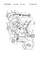
- FIG. 2is a diagrammatic perspective view of another embodiment of an inspiratory muscle training device according to the present invention.
- FIG. 3is a further diagrammatic perspective view of the inspiratory muscle training device shown in FIG. 2;
- FIG. 4is an exploded perspective view of a further embodiment of an inspiratory muscle training device according to the present invention.
- FIG. 5is a diagrammatic illustration of the manner of operation of a further embodiment of part of an inspiratory muscle training device according to the present invention.
- FIG. 1shows diagrammatically one embodiment of that part of an inspiratory muscle training device which applies variable loading to the inspiratory muscles of the user.
- FIG. 1shows a primary valve member 1 which is biased towards a closed position by a compression spring 3 .
- the primary valveis opened at a predetermined variable threshold pressure as a result of inspiration by the user as will be explained in more detail hereinafter.
- the initial threshold pressure at which the valve member 1 opensis determined by a threaded adjusting member 5 for increasing and decreasing the closure force and therefore the pressure at which the valve member 1 opens, the greater the degree of compression of the spring 3 , the greater the initial threshold pressure.
- the spring 3acts on the valve member 1 by way of a lever 7 which is pivotable about a fulcrum 9 .
- Fulcrum 9is provided on a rod 11 which is movable in the longitudinal direction of the lever 7 so as to vary the location of the fulcrum 9 along the lever.
- the mechanical advantagewhen the fulcrum is in a position relatively close to the valve member 1 (for example, generally mid-way along the lever 7 at the commencement of inspiration) the mechanical advantage is such that the compression spring 3 causes the threshold pressure at which the valve opens to be relatively high and when the fulcrum is in a position relatively close to the compression spring 3 the mechanical advantage is such that the compression spring causes the threshold pressure at which the valve opens to be relatively low or even substantially zero, with the threshold pressure varying according to the location of the fulcrum 9 intermediate these positions.
- the rod 11is connected to a diaphragm 13 provided in an evacuable chamber 15 .
- the chamber 15is also provided with a one-way exhaust valve 17 which allows the diaphragm to be compressed (by means not shown) into the chamber 15 prior to the user taking a breath and for air in the chamber to be exhausted through the valve 17 . An initial partial vacuum is therefore created in the chamber 15 .
- Biasing means 19acts on the rod 11 to bias the same in a direction such that the fulcrum is in a position relatively close to the compression spring 3 and the mechanical advantage is such that the compression spring 3 causes the threshold pressure at which the valve member 1 opens to be relatively low.
- the biasing means 19alone cannot cause the rod 11 to move against the partial vacuum in the chamber 15 .
- the chamber 15is additionally provided with a secondary valve 21 , the opening area of which is adjustable by way of a threaded adjusting member 23 .
- the secondary valve 21is mechanically linked (shown diagrammatically at 25 ) to the primary valve member 1 such that air is allowed to flow through the secondary valve and into the chamber 15 at a rate which is proportional to the flow of air past the valve member 1 . Additionally, the closure force of the secondary valve 21 varies according to the closure force of the primary valve member 1 .
- the volume of air passing through the secondary valve 21 as a proportion of the volume of air passing the primary valve member 1can be varied, for example by providing a plurality of openings in a fixed member and in a movable member such that the degree of overlap of the openings in the two members can be varied, such as by relative rotation.
- the flow of air into the chamber 15reduces the effect of the partial vacuum and allows the diaphragm 13 to move and consequently allows the biasing member 19 to move the rod 11 , and therefore the diaphragm, to restore the partial vacuum and consequently to move the fulcrum 9 closer to the compression spring 3 .
- the effect of thisis to reduce the threshold pressure at which the primary valve member 1 opens from an initial value to a progressively lower value as a function of the volume of air passing through the valve member.
- the adjusting member 5can be used to adjust the initial threshold pressure at which the primary valve member opens, while the adjusting member 23 can be used to adjust the rate at which the fulcrum moves, and thus the rate at which the threshold pressure reduces, in response to the passage of a predetermined volume of air through the primary valve (that is by varying the flow rate through the secondary valve relative to the flow rate through the primary valve).
- FIGS. 2 and 3has a mouthpiece 27 for drawing air through the primary valve member (not shown) in a valve chamber 29 , the valve member being operated by way of a valve stem 31 (FIG. 2 ).
- the valve stemis pivotably mounted on lever 7 and is additionally connected to a secondary valve provided with a valve chamber 33 .
- Valve chamber 33communicates with the interior of the diaphragm chamber 15 by way of a passage 34 to allow air from the secondary valve to flow into the diaphragm chamber.
- the compression springalso acts on lever 7 by way of a pivotably mounted pin or the like 35 (FIG. 2 ), part of the threaded adjusting member 5 being shown in FIG. 3 .
- Rod 11is shown in FIG. 2 and extends out of the chamber 15 by way of a seal which is not shown in detail and the free end of the rod acts on a pivot pin 37 by way of a pair of parallel levers 41 .
- the pivot pin 37forms the fulcrum either directly or by way of a roller provided on the pivot pin 37 and engages against a contoured surface 39 formed on the lever 7 .
- the pivot pin 37is mounted towards the end of the pair of parallel levers 41 which are pivotably mounted at the other ends thereof (not shown) for receiving the free end of the rod 11 .
- Biasing means 19 in the form of a torsion springis shown in FIG. 3, the torsion spring conveniently being positioned around an exhaust port for the diaphragm chamber.
- the rod 11(which in the embodiment of FIGS. 2 and 3 passes through the wall of the diaphragm chamber and therefore operates in the opposite sense to that shown in FIG. 1) is biased to move to the right as shown in FIG. 3 and moves the fulcrum progressively towards the point at which the compression spring acts on the lever 7 thereby reducing the threshold pressure at which the primary valve opens.
- the fulcrumcould be mounted on a lever which rotates about a remote centre.
- the manner in which the opening pressure of the primary valve variesis additionally influenced by the contour provided on the lever 7 , the contour determining the degree of compression of the spring in a manner which can be varied according to need as will readily be understood by the skilled person.
- exhaled airis used to reset the diaphragm and to urge the rod 11 towards the left as shown in FIG. 2 and to restore the partial vacuum in the chamber by expelling air through the one-way exhaust valve.
- FIG. 4differs from that shown in FIGS. 2 and 3 in that the exhaust port for the diaphragm chamber 15 is on the opposite side of the chamber.
- FIG. 4shows a number of aspects of the device according to the invention in more detail.
- the diaphragm chamber 15forms part of a chassis 45 for mounting the remaining components of the device, the adjusting member 5 , for example, being received in the chassis in a manner which permits the application of a variable pressure on the underside (as shown in FIG. 4) of the lever 7 an arrow showing the actual location of a pivot member 35 attached to a sleeve 47 for the spring 3 .
- the valve stem 31 , lever 7 and components for adjusting the fulcrumare concealed in use by a cover 49 .
- FIG. 4shows more clearly how the diaphragm 13 may be reset.
- Exhaled airpasses through a one-way valve 51 to the duct 43 and encounters a baffle 53 which is slidably mounted on pins 55 provided on a support 57 for the diaphragm.
- the baffle 53is a relatively close fit to the walls of a closure member 59 and is therefore urged by the exhaled air towards the diaphragm 13 and, in turn, urges the diaphragm and the rod 11 to the left as shown in FIG. 4 .
- This movement of the diaphragmcompresses the air in the chamber 15 and urges the same through the one-way exhaust valve 17 so as to restore the partial vacuum within the chamber.
- Further movement of the baffle 53reveals openings in the closure member 59 which allow the exhaled air to escape to atmosphere.
- FIG. 5is a partial illustration showing the manner of operation of a further embodiment of an inspiratory muscle training device according to the present invention.
- a paddle wheel impeller 101is positioned in an inlet (not shown) of the device such that the amount of rotation of the impeller is dependent on the volume of air which passes through a downstream valve 103 .
- Rotation of the impeller 101is passed through reduction gearing including, for example, a worm gear 105 and toothed gears 107 , 109 .
- Out put from the reduction gearingis by way of a rotating shaft 111 which rotates a face cam 113 relative to a further non-rotatable face cam 115 .
- Face cam 115is biased towards face can 113 by means of a coil spring 117 or the like, while biasing means such as coil spring 119 acts between the face cam 115 and a pivotable lever mechanism 121 to determine a threshold pressure at which the valve 103 opens in dependence on the degree of rotation of the cams 113 , 115 .
- the initial threshold pressurecan be adjusted as indicated by arrows by moving a fulcrum point 123 about which the lever mechanism 121 pivots.
- the impeller 101is arranged such that a variable proportion of the air passing through the valve 103 by-passes the impeller and therefore does not give rise to rotation thereof.
- the amount of air by-passing the impellercan be adjusted for each user by simple experiments such that the cam 113 rotates substantially 360 degrees for each inspiratory (inhalation) cycle.
- the inspiratory muscle training devicepermits ambulatory use. That is, it enables the user to use the device while exercising.
- the inspiratory muscle training deviceimposes a load which varies according to lung volume and hence muscle strength to provide a resistance that is a constant fraction of maximal strength during inspiration.
- the inspiratory muscle training devicealso has medical applications.
- the ability to control the variable pressure/volume loading profile achieved with variable pressure decay and initial opening pressureis more appropriate for patients with lung disease than the current threshold devices. This is primarily due to the fact that fixed loading is unsympathetic to the diverse and complex nature of breathing patterns observed in such patients.
- inspiratory muscle training deviceis not restricted to use by humans and can be used for training the inspiratory muscles of other animals, particularly horses and dogs.
Landscapes
- Health & Medical Sciences (AREA)
- Pulmonology (AREA)
- General Health & Medical Sciences (AREA)
- Physical Education & Sports Medicine (AREA)
- Measurement Of The Respiration, Hearing Ability, Form, And Blood Characteristics Of Living Organisms (AREA)
- Orthopedics, Nursing, And Contraception (AREA)
- Massaging Devices (AREA)
- Respiratory Apparatuses And Protective Means (AREA)
- Percussion Or Vibration Massage (AREA)
- Rehabilitation Tools (AREA)
Abstract
Description
Claims (15)
Applications Claiming Priority (3)
| Application Number | Priority Date | Filing Date | Title |
|---|---|---|---|
| EP98308706AEP0997168A1 (en) | 1998-10-23 | 1998-10-23 | Inspiratory muscle training device with variable loading |
| EP98308706 | 1998-10-23 | ||
| PCT/EP1999/008146WO2000024476A1 (en) | 1998-10-23 | 1999-10-21 | Inspiratory muscle training device with variable loading |
Publications (1)
| Publication Number | Publication Date |
|---|---|
| US6554746B1true US6554746B1 (en) | 2003-04-29 |
Family
ID=8235122
Family Applications (1)
| Application Number | Title | Priority Date | Filing Date |
|---|---|---|---|
| US09/830,006Expired - Fee RelatedUS6554746B1 (en) | 1998-10-23 | 1999-10-21 | Inspiratory muscle training device with variable loading |
Country Status (9)
| Country | Link |
|---|---|
| US (1) | US6554746B1 (en) |
| EP (2) | EP0997168A1 (en) |
| JP (1) | JP2002528197A (en) |
| AT (1) | ATE291469T1 (en) |
| AU (1) | AU1044100A (en) |
| CA (1) | CA2347751C (en) |
| DE (1) | DE69924399T2 (en) |
| ES (1) | ES2241333T3 (en) |
| WO (1) | WO2000024476A1 (en) |
Cited By (24)
| Publication number | Priority date | Publication date | Assignee | Title |
|---|---|---|---|---|
| US20090264255A1 (en)* | 2008-04-16 | 2009-10-22 | Christian Tutsch | System and method for improving endurance of inspiratory muscles |
| US8251876B2 (en) | 2008-04-22 | 2012-08-28 | Hill-Rom Services, Inc. | Breathing exercise apparatus |
| US20130276787A1 (en)* | 2008-03-10 | 2013-10-24 | University of Florida Research Founation, Inc. | Automated inspiratory muscle training for patients receiving mechanical ventilation |
| US8590533B2 (en) | 2010-10-14 | 2013-11-26 | Casey Danford | Adjustable inhalation resistence exercise device |
| US9067086B2 (en) | 2011-06-07 | 2015-06-30 | Casey J. Danford | High performance ventilatory training mask incorporating multiple and adjustable air admittance valves for replicating various encountered altitude resistances |
| US9180271B2 (en) | 2012-03-05 | 2015-11-10 | Hill-Rom Services Pte. Ltd. | Respiratory therapy device having standard and oscillatory PEP with nebulizer |
| USD765237S1 (en) | 2015-11-04 | 2016-08-30 | Trainingmask, Llc | Resistance breathing device |
| USD767754S1 (en) | 2015-11-02 | 2016-09-27 | Trainingmask, Llc | Resistance and filtration breathing device |
| US9579540B1 (en) | 2016-01-06 | 2017-02-28 | Trainingmask, L.L.C. | Resistance breathing device |
| US9643048B1 (en) | 2016-09-09 | 2017-05-09 | TrainingMask L.L.C. | Resistance breathing device |
| US9707444B1 (en) | 2016-03-22 | 2017-07-18 | Trainingmask Llc | Resistance breathing device |
| USD811581S1 (en) | 2016-03-03 | 2018-02-27 | Trainingmask Llc | Resistance breathing device |
| US9914017B2 (en) | 2016-05-17 | 2018-03-13 | Patrick McKeown | Sports mask system |
| US9956439B2 (en) | 2014-09-30 | 2018-05-01 | Blast Mask, LLC | Breathing equipment training |
| USD820974S1 (en) | 2016-09-30 | 2018-06-19 | TrainingMask L.L.C. | Resistance breathing device |
| US20180280758A1 (en)* | 2017-03-28 | 2018-10-04 | Bo Tao | Infinitely adjustable training mask with an air filter and a drinking device |
| US10322312B1 (en) | 2018-06-01 | 2019-06-18 | TrainingMask L.L.C. | Resistance and filtration breathing device |
| US10328293B2 (en) | 2014-09-30 | 2019-06-25 | Blast Mask, LLC | Breathing equipment training |
| US10905836B2 (en) | 2015-04-02 | 2021-02-02 | Hill-Rom Services Pte. Ltd. | Manifold for respiratory device |
| US11040243B2 (en) | 2018-03-23 | 2021-06-22 | Breathe With B, Inc. | Breathing device |
| US11071882B2 (en)* | 2014-09-30 | 2021-07-27 | Blast Mask, LLC | Breathing equipment training |
| USD952130S1 (en) | 2019-09-30 | 2022-05-17 | TrainingMask L.L.C. | Mask insert |
| WO2023012626A1 (en)* | 2021-08-01 | 2023-02-09 | Reuvers Eduard Johannis Adrianus | Automated breath resistance training apparatus |
| USD1004767S1 (en) | 2020-05-29 | 2023-11-14 | Trainingmask L.L.C | Filtration mask |
Families Citing this family (8)
| Publication number | Priority date | Publication date | Assignee | Title |
|---|---|---|---|---|
| EP1191977A1 (en)* | 1999-06-18 | 2002-04-03 | Powerlung Inc | Pulmonary exercise device |
| JP4625161B2 (en)* | 2000-07-19 | 2011-02-02 | 有限会社エース | Breathing exercise equipment |
| GB2451593B (en)* | 2005-04-14 | 2009-09-30 | Ramer Ltd | Exercise device |
| GB0507547D0 (en)* | 2005-04-14 | 2005-05-18 | Ramer Ltd | Exercise device and methods of exercising |
| GB0811981D0 (en)* | 2008-07-01 | 2008-07-30 | Hab Internat Ltd | Respiratory muscle training device |
| ES2422529B1 (en)* | 2012-03-07 | 2014-07-22 | Jose Luis Gonzalez Montesinos | RESPIRATORY MUSCULATURE STRENGTHENING DEVICE |
| BR212016024092Y1 (en)* | 2014-04-15 | 2020-08-11 | Fundación Valle Del Lili | DEVICE TO BE USED AS INSTRUMENTAL PULMONARY RE-EXPANSION TECHNIQUE |
| RU2688796C1 (en)* | 2018-05-07 | 2019-05-22 | Общество с ограниченной ответственностью "БФСофт" (ООО "БФСофт") | Breathing trainer |
Citations (8)
| Publication number | Priority date | Publication date | Assignee | Title |
|---|---|---|---|---|
| US793177A (en)* | 1905-01-23 | 1905-06-27 | Henry G Cady | Lung-tester and toy. |
| US1988221A (en)* | 1931-04-27 | 1935-01-15 | Michael Reese Hospital Of Chic | Metabolism machine |
| US2121311A (en)* | 1934-04-05 | 1938-06-21 | Gasaccumulator Svenska Ab | Respiration apparatus |
| US3319624A (en)* | 1964-01-15 | 1967-05-16 | Univ Iowa State Res Found Inc | Apparatus for measuring breath volume |
| US3395699A (en)* | 1965-04-28 | 1968-08-06 | Puritan Compressed Gas Corp | Spirometer |
| US3467078A (en)* | 1965-05-10 | 1969-09-16 | Bird F M | Spirometer |
| US3669097A (en)* | 1969-06-19 | 1972-06-13 | Edward Fitz | Lung exercising apparatus and method |
| US4854574A (en)* | 1988-03-15 | 1989-08-08 | 501 Healthscan, Inc. | Inspirator muscle trainer |
Family Cites Families (3)
| Publication number | Priority date | Publication date | Assignee | Title |
|---|---|---|---|---|
| FR459463A (en)* | 1913-06-19 | 1913-11-06 | Rene Marie Louis Boureau | Dynamometer and pulmonary exerciser |
| FR2379291A1 (en)* | 1977-02-04 | 1978-09-01 | Cahen Claude | Unit for treating bronchial ailment - has tube into which patient breathes to move piston against spring and magnetic pressure to uncover ports |
| GB2278545B (en) | 1993-04-21 | 1997-02-19 | Univ Loughborough | Inspiratory muscle training device |
- 1998
- 1998-10-23EPEP98308706Apatent/EP0997168A1/ennot_activeWithdrawn
- 1999
- 1999-10-21JPJP2000578077Apatent/JP2002528197A/ennot_activeCeased
- 1999-10-21AUAU10441/00Apatent/AU1044100A/ennot_activeAbandoned
- 1999-10-21EPEP99953950Apatent/EP1123142B1/ennot_activeExpired - Lifetime
- 1999-10-21CACA002347751Apatent/CA2347751C/ennot_activeExpired - Fee Related
- 1999-10-21ESES99953950Tpatent/ES2241333T3/ennot_activeExpired - Lifetime
- 1999-10-21WOPCT/EP1999/008146patent/WO2000024476A1/enactiveIP Right Grant
- 1999-10-21ATAT99953950Tpatent/ATE291469T1/ennot_activeIP Right Cessation
- 1999-10-21USUS09/830,006patent/US6554746B1/ennot_activeExpired - Fee Related
- 1999-10-21DEDE69924399Tpatent/DE69924399T2/ennot_activeExpired - Fee Related
Patent Citations (8)
| Publication number | Priority date | Publication date | Assignee | Title |
|---|---|---|---|---|
| US793177A (en)* | 1905-01-23 | 1905-06-27 | Henry G Cady | Lung-tester and toy. |
| US1988221A (en)* | 1931-04-27 | 1935-01-15 | Michael Reese Hospital Of Chic | Metabolism machine |
| US2121311A (en)* | 1934-04-05 | 1938-06-21 | Gasaccumulator Svenska Ab | Respiration apparatus |
| US3319624A (en)* | 1964-01-15 | 1967-05-16 | Univ Iowa State Res Found Inc | Apparatus for measuring breath volume |
| US3395699A (en)* | 1965-04-28 | 1968-08-06 | Puritan Compressed Gas Corp | Spirometer |
| US3467078A (en)* | 1965-05-10 | 1969-09-16 | Bird F M | Spirometer |
| US3669097A (en)* | 1969-06-19 | 1972-06-13 | Edward Fitz | Lung exercising apparatus and method |
| US4854574A (en)* | 1988-03-15 | 1989-08-08 | 501 Healthscan, Inc. | Inspirator muscle trainer |
Non-Patent Citations (1)
| Title |
|---|
| International Search Report Feb. 9, 2000. |
Cited By (32)
| Publication number | Priority date | Publication date | Assignee | Title |
|---|---|---|---|---|
| US20130276787A1 (en)* | 2008-03-10 | 2013-10-24 | University of Florida Research Founation, Inc. | Automated inspiratory muscle training for patients receiving mechanical ventilation |
| US10245399B2 (en)* | 2008-03-10 | 2019-04-02 | University Of Florida Research Foundation, Inc. | Automated inspiratory muscle training for patients receiving mechanical ventilation |
| US20090264255A1 (en)* | 2008-04-16 | 2009-10-22 | Christian Tutsch | System and method for improving endurance of inspiratory muscles |
| US8272378B2 (en) | 2008-04-16 | 2012-09-25 | Eumedics Medlzintechnik Und Marketing Gmbh | System and method for improving endurance of inspiratory muscles |
| US8251876B2 (en) | 2008-04-22 | 2012-08-28 | Hill-Rom Services, Inc. | Breathing exercise apparatus |
| US8590533B2 (en) | 2010-10-14 | 2013-11-26 | Casey Danford | Adjustable inhalation resistence exercise device |
| US9067086B2 (en) | 2011-06-07 | 2015-06-30 | Casey J. Danford | High performance ventilatory training mask incorporating multiple and adjustable air admittance valves for replicating various encountered altitude resistances |
| US9180271B2 (en) | 2012-03-05 | 2015-11-10 | Hill-Rom Services Pte. Ltd. | Respiratory therapy device having standard and oscillatory PEP with nebulizer |
| US9956439B2 (en) | 2014-09-30 | 2018-05-01 | Blast Mask, LLC | Breathing equipment training |
| US10328293B2 (en) | 2014-09-30 | 2019-06-25 | Blast Mask, LLC | Breathing equipment training |
| US11071882B2 (en)* | 2014-09-30 | 2021-07-27 | Blast Mask, LLC | Breathing equipment training |
| US10905836B2 (en) | 2015-04-02 | 2021-02-02 | Hill-Rom Services Pte. Ltd. | Manifold for respiratory device |
| US10905837B2 (en) | 2015-04-02 | 2021-02-02 | Hill-Rom Services Pte. Ltd. | Respiratory therapy cycle control and feedback |
| US11992611B2 (en) | 2015-04-02 | 2024-05-28 | Hill-Rom Services Pte. Ltd. | Respiratory therapy apparatus control |
| USD767754S1 (en) | 2015-11-02 | 2016-09-27 | Trainingmask, Llc | Resistance and filtration breathing device |
| USD765237S1 (en) | 2015-11-04 | 2016-08-30 | Trainingmask, Llc | Resistance breathing device |
| US9579540B1 (en) | 2016-01-06 | 2017-02-28 | Trainingmask, L.L.C. | Resistance breathing device |
| USD811581S1 (en) | 2016-03-03 | 2018-02-27 | Trainingmask Llc | Resistance breathing device |
| US9707444B1 (en) | 2016-03-22 | 2017-07-18 | Trainingmask Llc | Resistance breathing device |
| US9914017B2 (en) | 2016-05-17 | 2018-03-13 | Patrick McKeown | Sports mask system |
| US9802079B1 (en) | 2016-09-09 | 2017-10-31 | TrainingMask L.L.C. | Resistance breathing device |
| US9643048B1 (en) | 2016-09-09 | 2017-05-09 | TrainingMask L.L.C. | Resistance breathing device |
| USD820974S1 (en) | 2016-09-30 | 2018-06-19 | TrainingMask L.L.C. | Resistance breathing device |
| US10478667B2 (en)* | 2017-03-28 | 2019-11-19 | Bo Tao | Infinitely adjustable training mask with an air filter and a drinking device |
| US20180280758A1 (en)* | 2017-03-28 | 2018-10-04 | Bo Tao | Infinitely adjustable training mask with an air filter and a drinking device |
| US11040243B2 (en) | 2018-03-23 | 2021-06-22 | Breathe With B, Inc. | Breathing device |
| US11040242B2 (en) | 2018-03-23 | 2021-06-22 | Breathe With B, Inc. | Breathing device |
| US11571605B2 (en) | 2018-03-23 | 2023-02-07 | Breathe With B, Inc. | Breathing app |
| US10322312B1 (en) | 2018-06-01 | 2019-06-18 | TrainingMask L.L.C. | Resistance and filtration breathing device |
| USD952130S1 (en) | 2019-09-30 | 2022-05-17 | TrainingMask L.L.C. | Mask insert |
| USD1004767S1 (en) | 2020-05-29 | 2023-11-14 | Trainingmask L.L.C | Filtration mask |
| WO2023012626A1 (en)* | 2021-08-01 | 2023-02-09 | Reuvers Eduard Johannis Adrianus | Automated breath resistance training apparatus |
Also Published As
| Publication number | Publication date |
|---|---|
| JP2002528197A (en) | 2002-09-03 |
| AU1044100A (en) | 2000-05-15 |
| DE69924399T2 (en) | 2006-03-09 |
| CA2347751C (en) | 2008-04-29 |
| EP1123142A1 (en) | 2001-08-16 |
| EP1123142B1 (en) | 2005-03-23 |
| CA2347751A1 (en) | 2000-05-04 |
| ATE291469T1 (en) | 2005-04-15 |
| WO2000024476A1 (en) | 2000-05-04 |
| EP0997168A1 (en) | 2000-05-03 |
| DE69924399D1 (en) | 2005-04-28 |
| ES2241333T3 (en) | 2005-10-16 |
Similar Documents
| Publication | Publication Date | Title |
|---|---|---|
| US6554746B1 (en) | Inspiratory muscle training device with variable loading | |
| US4854574A (en) | Inspirator muscle trainer | |
| US4143872A (en) | Lung volume exerciser | |
| AU2009266078B2 (en) | Respiratory muscle training device | |
| US6083141A (en) | Portable respiratory exercise apparatus and method for using the same | |
| US5937857A (en) | Backpressure-modulating cartridge for breathing mask | |
| US20150031506A1 (en) | Respiratory muscle endurance training device and method for the use thereof | |
| EP2491987B1 (en) | Device for evaluating and training respiratory function, on both inspiration and expiration | |
| CA2212642A1 (en) | A portable, personal breathing apparatus | |
| US9233274B2 (en) | Combination spirometer and PEP breathing exerciser | |
| GB2070432A (en) | Ventilatory muscle training apparatus | |
| US3511228A (en) | Bronchial dilator for patients suffering from emphysema and asthma or the like | |
| JP2002345963A (en) | Device and method for enhancing remained air quantity by respiratory muscle activity | |
| EP1397993A1 (en) | A rotary variable orifice valve | |
| EP0984820B1 (en) | Respiratory muscle training device | |
| KR102613921B1 (en) | Respiration analysis and training apparatus | |
| KR102617848B1 (en) | Respiration Rehabilitation Apparatus for Measuring Lung Capacity and Breathing Pressure, and Training Respiratory Resistance | |
| US2483722A (en) | Oxygen valve | |
| US5511544A (en) | Non-resistant respiratory exerciser | |
| RU1801469C (en) | Device for training respiratory muscle | |
| US20040063544A1 (en) | Apparatus for measuring the strength of a person's respiratory muscles | |
| RU2033137C1 (en) | Device for curing respiratory insufficiency | |
| RU1793913C (en) | Apparatus for breathing exercises | |
| Robinson et al. | A pressure-cycled ventilator with multiple functional behaviour | |
| DE2141579C3 (en) | Circulatory breathing apparatus |
Legal Events
| Date | Code | Title | Description |
|---|---|---|---|
| AS | Assignment | Owner name:IMT TECHNOLOGIES LIMITED, UNITED KINGDOM Free format text:ASSIGNMENT OF ASSIGNORS INTEREST;ASSIGNOR:MCCONNELL, ALISON KAY;REEL/FRAME:012046/0119 Effective date:20010622 Owner name:IMT TECHNOLOGIES, LIMITED, UNITED KINGDOM Free format text:ASSIGNMENT OF ASSIGNORS INTEREST;ASSIGNOR:CAINE, MICHAEL PETER;REEL/FRAME:012046/0215 Effective date:20010706 Owner name:IMT TECHNOLOGIES, LIMITED, UNITED KINGDOM Free format text:ASSIGNMENT OF ASSIGNORS INTEREST;ASSIGNOR:LACY, GRAHAM KEITH;REEL/FRAME:012046/0217 Effective date:20010621 | |
| AS | Assignment | Owner name:LEISURE SYSTEMS INTERNATIONAL LTD., UNITED KINGDOM Free format text:ASSIGNMENT OF ASSIGNORS INTEREST;ASSIGNOR:BIRMINGHAM RESEARCH AND DEVELOPMENT LTD.;REEL/FRAME:016135/0978 Effective date:20010314 Owner name:BIRMINGHAM RESEARCH AND DEVELOPMENT LTD., UNITED K Free format text:MEMORANDUM OF SALE;ASSIGNOR:IMT TECHNOLOGIES LTD.;REEL/FRAME:016145/0664 Effective date:20000929 | |
| AS | Assignment | Owner name:GAIAM LIMITED, UNITED KINGDOM Free format text:CHANGE OF NAME;ASSIGNOR:LEISURE SYSTEMS INTERNATIONAL LIMITED;REEL/FRAME:016945/0799 Effective date:20050308 | |
| FEPP | Fee payment procedure | Free format text:PAT HOLDER CLAIMS SMALL ENTITY STATUS, ENTITY STATUS SET TO SMALL (ORIGINAL EVENT CODE: LTOS); ENTITY STATUS OF PATENT OWNER: SMALL ENTITY | |
| FPAY | Fee payment | Year of fee payment:4 | |
| REMI | Maintenance fee reminder mailed | ||
| LAPS | Lapse for failure to pay maintenance fees | ||
| STCH | Information on status: patent discontinuation | Free format text:PATENT EXPIRED DUE TO NONPAYMENT OF MAINTENANCE FEES UNDER 37 CFR 1.362 | |
| FP | Lapsed due to failure to pay maintenance fee | Effective date:20110429 |