US6554091B2 - Engine output controller - Google Patents
Engine output controllerDownload PDFInfo
- Publication number
- US6554091B2 US6554091B2US10/034,685US3468501AUS6554091B2US 6554091 B2US6554091 B2US 6554091B2US 3468501 AUS3468501 AUS 3468501AUS 6554091 B2US6554091 B2US 6554091B2
- Authority
- US
- United States
- Prior art keywords
- value
- engine
- speed
- engine speed
- control system
- Prior art date
- Legal status (The legal status is an assumption and is not a legal conclusion. Google has not performed a legal analysis and makes no representation as to the accuracy of the status listed.)
- Expired - Fee Related
Links
Images


Classifications
- B—PERFORMING OPERATIONS; TRANSPORTING
- B60—VEHICLES IN GENERAL
- B60K—ARRANGEMENT OR MOUNTING OF PROPULSION UNITS OR OF TRANSMISSIONS IN VEHICLES; ARRANGEMENT OR MOUNTING OF PLURAL DIVERSE PRIME-MOVERS IN VEHICLES; AUXILIARY DRIVES FOR VEHICLES; INSTRUMENTATION OR DASHBOARDS FOR VEHICLES; ARRANGEMENTS IN CONNECTION WITH COOLING, AIR INTAKE, GAS EXHAUST OR FUEL SUPPLY OF PROPULSION UNITS IN VEHICLES
- B60K28/00—Safety devices for propulsion-unit control, specially adapted for, or arranged in, vehicles, e.g. preventing fuel supply or ignition in the event of potentially dangerous conditions
- B60K28/10—Safety devices for propulsion-unit control, specially adapted for, or arranged in, vehicles, e.g. preventing fuel supply or ignition in the event of potentially dangerous conditions responsive to conditions relating to the vehicle
- B60K28/16—Safety devices for propulsion-unit control, specially adapted for, or arranged in, vehicles, e.g. preventing fuel supply or ignition in the event of potentially dangerous conditions responsive to conditions relating to the vehicle responsive to, or preventing, spinning or skidding of wheels
- B—PERFORMING OPERATIONS; TRANSPORTING
- B60—VEHICLES IN GENERAL
- B60K—ARRANGEMENT OR MOUNTING OF PROPULSION UNITS OR OF TRANSMISSIONS IN VEHICLES; ARRANGEMENT OR MOUNTING OF PLURAL DIVERSE PRIME-MOVERS IN VEHICLES; AUXILIARY DRIVES FOR VEHICLES; INSTRUMENTATION OR DASHBOARDS FOR VEHICLES; ARRANGEMENTS IN CONNECTION WITH COOLING, AIR INTAKE, GAS EXHAUST OR FUEL SUPPLY OF PROPULSION UNITS IN VEHICLES
- B60K31/00—Vehicle fittings, acting on a single sub-unit only, for automatically controlling vehicle speed, i.e. preventing speed from exceeding an arbitrarily established velocity or maintaining speed at a particular velocity, as selected by the vehicle operator
- B60K31/02—Vehicle fittings, acting on a single sub-unit only, for automatically controlling vehicle speed, i.e. preventing speed from exceeding an arbitrarily established velocity or maintaining speed at a particular velocity, as selected by the vehicle operator including electrically actuated servomechanism
- B60K31/04—Vehicle fittings, acting on a single sub-unit only, for automatically controlling vehicle speed, i.e. preventing speed from exceeding an arbitrarily established velocity or maintaining speed at a particular velocity, as selected by the vehicle operator including electrically actuated servomechanism and means for comparing one electrical quantity, e.g. voltage, pulse, waveform, flux, or the like, with another quantity of a like kind, which comparison means is involved in the development of an electrical signal which is fed into the controlling means
- F—MECHANICAL ENGINEERING; LIGHTING; HEATING; WEAPONS; BLASTING
- F02—COMBUSTION ENGINES; HOT-GAS OR COMBUSTION-PRODUCT ENGINE PLANTS
- F02D—CONTROLLING COMBUSTION ENGINES
- F02D31/00—Use of speed-sensing governors to control combustion engines, not otherwise provided for
- F02D31/001—Electric control of rotation speed
- F02D31/002—Electric control of rotation speed controlling air supply
- F—MECHANICAL ENGINEERING; LIGHTING; HEATING; WEAPONS; BLASTING
- F02—COMBUSTION ENGINES; HOT-GAS OR COMBUSTION-PRODUCT ENGINE PLANTS
- F02D—CONTROLLING COMBUSTION ENGINES
- F02D41/00—Electrical control of supply of combustible mixture or its constituents
- F02D41/02—Circuit arrangements for generating control signals
- F02D41/021—Introducing corrections for particular conditions exterior to the engine
- B—PERFORMING OPERATIONS; TRANSPORTING
- B60—VEHICLES IN GENERAL
- B60W—CONJOINT CONTROL OF VEHICLE SUB-UNITS OF DIFFERENT TYPE OR DIFFERENT FUNCTION; CONTROL SYSTEMS SPECIALLY ADAPTED FOR HYBRID VEHICLES; ROAD VEHICLE DRIVE CONTROL SYSTEMS FOR PURPOSES NOT RELATED TO THE CONTROL OF A PARTICULAR SUB-UNIT
- B60W2710/00—Output or target parameters relating to a particular sub-units
- B60W2710/06—Combustion engines, Gas turbines
- B60W2710/0644—Engine speed
- B60W2710/0661—Speed change rate
- B—PERFORMING OPERATIONS; TRANSPORTING
- B60—VEHICLES IN GENERAL
- B60W—CONJOINT CONTROL OF VEHICLE SUB-UNITS OF DIFFERENT TYPE OR DIFFERENT FUNCTION; CONTROL SYSTEMS SPECIALLY ADAPTED FOR HYBRID VEHICLES; ROAD VEHICLE DRIVE CONTROL SYSTEMS FOR PURPOSES NOT RELATED TO THE CONTROL OF A PARTICULAR SUB-UNIT
- B60W2710/00—Output or target parameters relating to a particular sub-units
- B60W2710/06—Combustion engines, Gas turbines
- B60W2710/0666—Engine torque
- B—PERFORMING OPERATIONS; TRANSPORTING
- B60—VEHICLES IN GENERAL
- B60W—CONJOINT CONTROL OF VEHICLE SUB-UNITS OF DIFFERENT TYPE OR DIFFERENT FUNCTION; CONTROL SYSTEMS SPECIALLY ADAPTED FOR HYBRID VEHICLES; ROAD VEHICLE DRIVE CONTROL SYSTEMS FOR PURPOSES NOT RELATED TO THE CONTROL OF A PARTICULAR SUB-UNIT
- B60W2710/00—Output or target parameters relating to a particular sub-units
- B60W2710/10—Change speed gearings
- B60W2710/1011—Input shaft speed, e.g. turbine speed
- B—PERFORMING OPERATIONS; TRANSPORTING
- B60—VEHICLES IN GENERAL
- B60W—CONJOINT CONTROL OF VEHICLE SUB-UNITS OF DIFFERENT TYPE OR DIFFERENT FUNCTION; CONTROL SYSTEMS SPECIALLY ADAPTED FOR HYBRID VEHICLES; ROAD VEHICLE DRIVE CONTROL SYSTEMS FOR PURPOSES NOT RELATED TO THE CONTROL OF A PARTICULAR SUB-UNIT
- B60W2720/00—Output or target parameters relating to overall vehicle dynamics
- B60W2720/10—Longitudinal speed
- B60W2720/106—Longitudinal acceleration
- F—MECHANICAL ENGINEERING; LIGHTING; HEATING; WEAPONS; BLASTING
- F02—COMBUSTION ENGINES; HOT-GAS OR COMBUSTION-PRODUCT ENGINE PLANTS
- F02D—CONTROLLING COMBUSTION ENGINES
- F02D11/00—Arrangements for, or adaptations to, non-automatic engine control initiation means, e.g. operator initiated
- F02D11/06—Arrangements for, or adaptations to, non-automatic engine control initiation means, e.g. operator initiated characterised by non-mechanical control linkages, e.g. fluid control linkages or by control linkages with power drive or assistance
- F02D11/10—Arrangements for, or adaptations to, non-automatic engine control initiation means, e.g. operator initiated characterised by non-mechanical control linkages, e.g. fluid control linkages or by control linkages with power drive or assistance of the electric type
- F02D2011/101—Arrangements for, or adaptations to, non-automatic engine control initiation means, e.g. operator initiated characterised by non-mechanical control linkages, e.g. fluid control linkages or by control linkages with power drive or assistance of the electric type characterised by the means for actuating the throttles
- F02D2011/103—Arrangements for, or adaptations to, non-automatic engine control initiation means, e.g. operator initiated characterised by non-mechanical control linkages, e.g. fluid control linkages or by control linkages with power drive or assistance of the electric type characterised by the means for actuating the throttles at least one throttle being alternatively mechanically linked to the pedal or moved by an electric actuator
- F—MECHANICAL ENGINEERING; LIGHTING; HEATING; WEAPONS; BLASTING
- F02—COMBUSTION ENGINES; HOT-GAS OR COMBUSTION-PRODUCT ENGINE PLANTS
- F02D—CONTROLLING COMBUSTION ENGINES
- F02D2200/00—Input parameters for engine control
- F02D2200/02—Input parameters for engine control the parameters being related to the engine
- F02D2200/04—Engine intake system parameters
- F02D2200/0404—Throttle position
- F—MECHANICAL ENGINEERING; LIGHTING; HEATING; WEAPONS; BLASTING
- F02—COMBUSTION ENGINES; HOT-GAS OR COMBUSTION-PRODUCT ENGINE PLANTS
- F02D—CONTROLLING COMBUSTION ENGINES
- F02D2200/00—Input parameters for engine control
- F02D2200/02—Input parameters for engine control the parameters being related to the engine
- F02D2200/04—Engine intake system parameters
- F02D2200/0406—Intake manifold pressure
- F—MECHANICAL ENGINEERING; LIGHTING; HEATING; WEAPONS; BLASTING
- F02—COMBUSTION ENGINES; HOT-GAS OR COMBUSTION-PRODUCT ENGINE PLANTS
- F02D—CONTROLLING COMBUSTION ENGINES
- F02D2200/00—Input parameters for engine control
- F02D2200/50—Input parameters for engine control said parameters being related to the vehicle or its components
- F02D2200/501—Vehicle speed
- F—MECHANICAL ENGINEERING; LIGHTING; HEATING; WEAPONS; BLASTING
- F02—COMBUSTION ENGINES; HOT-GAS OR COMBUSTION-PRODUCT ENGINE PLANTS
- F02D—CONTROLLING COMBUSTION ENGINES
- F02D2200/00—Input parameters for engine control
- F02D2200/70—Input parameters for engine control said parameters being related to the vehicle exterior
- F02D2200/703—Atmospheric pressure
- F—MECHANICAL ENGINEERING; LIGHTING; HEATING; WEAPONS; BLASTING
- F02—COMBUSTION ENGINES; HOT-GAS OR COMBUSTION-PRODUCT ENGINE PLANTS
- F02D—CONTROLLING COMBUSTION ENGINES
- F02D41/00—Electrical control of supply of combustible mixture or its constituents
- F02D41/02—Circuit arrangements for generating control signals
- F02D41/021—Introducing corrections for particular conditions exterior to the engine
- F02D41/0215—Introducing corrections for particular conditions exterior to the engine in relation with elements of the transmission
- F02D41/0225—Introducing corrections for particular conditions exterior to the engine in relation with elements of the transmission in relation with the gear ratio or shift lever position
- F—MECHANICAL ENGINEERING; LIGHTING; HEATING; WEAPONS; BLASTING
- F02—COMBUSTION ENGINES; HOT-GAS OR COMBUSTION-PRODUCT ENGINE PLANTS
- F02D—CONTROLLING COMBUSTION ENGINES
- F02D41/00—Electrical control of supply of combustible mixture or its constituents
- F02D41/02—Circuit arrangements for generating control signals
- F02D41/18—Circuit arrangements for generating control signals by measuring intake air flow
- F02D41/187—Circuit arrangements for generating control signals by measuring intake air flow using a hot wire flow sensor
- F—MECHANICAL ENGINEERING; LIGHTING; HEATING; WEAPONS; BLASTING
- F16—ENGINEERING ELEMENTS AND UNITS; GENERAL MEASURES FOR PRODUCING AND MAINTAINING EFFECTIVE FUNCTIONING OF MACHINES OR INSTALLATIONS; THERMAL INSULATION IN GENERAL
- F16H—GEARING
- F16H63/00—Control outputs from the control unit to change-speed- or reversing-gearings for conveying rotary motion or to other devices than the final output mechanism
- F16H63/40—Control outputs from the control unit to change-speed- or reversing-gearings for conveying rotary motion or to other devices than the final output mechanism comprising signals other than signals for actuating the final output mechanisms
- F16H63/50—Signals to an engine or motor
Definitions
- the inventionrelates generally to control systems for internal combustion engines, and more particularly, concerns a powertrain controller for a throttleless engine.
- SI enginesspark ignited (SI) engines and compression ignition (CI) engines.
- SI engine's poweris controlled through a process called throttling. Throttling controls the density of air that enters an engine's combustion chambers.
- the throttle systemis typically comprised of one or more throttle blades which are within the intake air stream. During engine idle or a closed throttle condition, the throttle blade closes off the air inlet creating a large pressure drop and density decrease. When the throttle is wide open, the throttle blade is generally parallel to the air stream and presents a minimal air restriction to inducted airflow. Under most engine operating conditions, the throttle blade is somewhere between fully open and fully closed thus presenting a controlled restriction of the intake airflow.
- Fuel in an SI engineis generally introduced into the inlet air stream to provide a combustible air fuel mixture.
- Fuel injectorsare often located in a common plenum feeding all of the cylinders on a multi-cylinder engine. When injected at this location, the engine is said to be throttle-body injected. Injectors can alternatively be located in the intake runners feeding the individual cylinder intake ports. This type of injection is referred to as port injection. Alternatively, fuel injectors can be located directly within each cylinder. This type of injection is referred to as a direct injection engine.
- Power output of an internal combustion enginecan also be controlled entirely by the amount of fuel introduced into the combustion chamber just prior to ignition.
- the enginetypically does not have a throttle. Air entering the engine is restricted only by the intake manifold design. Fuel is injected directly into the cylinder of the CI engine just prior to ignition, and ignition is caused by the high temperature generated during the piston compression stroke.
- the present inventionprovides an engine output control method and system for a vehicle having a throttleless engine system responsive to a desired engine speed signal.
- An engine output control method for a vehicle having a throttleless internal combustion engine system responsive to a desired engine speed signalincludes generating a driver demanded engine speed value corresponding to an operator input and generating a speed control system engine speed value corresponding to a predetermined speed value to permit vehicle operation at a constant speed by a speed control system.
- the methodarbitrates between the driver demanded engine speed value and the speed control system engine speed value to derive a first desired engine speed value. This value is limited by a vehicle speed limit value, engine speed limit value, and transmission speed limit value to generate a second desired engine speed value.
- the engineis then controlled as a function of the second desired engine speed value and an actual engine speed value.
- Control of the engine outputis accomplished by way of variable valve timing, fueling rate and/or fuel flow, and spark advance.
- a traction control value and transmission limiting valueare generated in the torque domain and arbitrated against the speed domain-based second desired engine speed value to control the engine output.
- valuesare generated in the acceleration domain to control the engine output. Specifically, values are generated for a driver demanded vehicle acceleration value corresponding to an accelerator pedal position; a speed control system vehicle acceleration value corresponding to a predetermined speed value to permit vehicle operation at a constant speed by a speed control system; a vehicle speed limit acceleration value corresponding to a maximum vehicle acceleration value to achieve a predetermined vehicle speed limit; and a traction control vehicle acceleration value corresponding to a maximum vehicle acceleration value to prevent wheel slip. These values are then arbitrated to derive a first desired vehicle acceleration value. The first desired vehicle acceleration value is limited by an engine speed limit value and transmission speed limit value to generate a second desired vehicle acceleration value. The resulting value can be used to control the engine output directly or converted to a desired engine acceleration value to control the engine output. Again, engine output is controlled by way of variable valve timing, fueling rate and/or fuel flow, and spark advance.
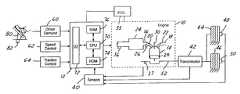
- FIG. 1is a schematic diagram of an internal combustion engine and associated control system according to one embodiment of the present invention.
- FIG. 2is a block diagram of one embodiment of the controller of FIG. 1 .
- FIG. 3is a block diagram of another embodiment of the controller of FIG. 1 .
- FIG. 4is a block diagram of another embodiment of the controller of FIG. 1 .
- FIG. 5is a block diagram of another embodiment of the controller of FIG. 1 .
- FIG. 1there is shown a schematic diagram of an internal combustion engine 10 and associated engine controller 12 in accordance with one embodiment of the present invention.
- the engine 10includes a plurality of combustion chambers 14 , one of which is shown.
- Each combustion chamber 14has an associated intake 16 and exhaust 18 operated by a respective valves 20 , 22 .
- Valves 20 , 22allow variable valve timing and are controlled electronically using electromagnetic actuators rather than a conventional cam arrangement.
- Combustionoccurs as a result of the intake of air and fuel from the intake manifold 24 and fuel injector 26 respectively, compression by the piston 28 and ignition by the spark plug 30 .
- Engine 10may also operate in a compression ignition mode wherein combustion occurs as a result of the intake of air and fuel and compression by the piston 28 without ignition by the spark plug 30 .
- Combustion gasestravel through the exhaust manifold 18 to the downstream catalytic converter (not shown) and are emitted out of the tailpipe. A portion of the exhaust gases may also be recirculated back through the intake manifold 24 to the engine cylinders 14 by way of an EGR valve (not shown).
- the engine 10is preferably a gaseous-fueled engine wherein gaseous fuel such as hydrogen is supplied to the engine 10 from a fuel supply 35 by way of the fuel injector 26 .
- gaseous fuelsuch as hydrogen
- the injector 26may be located adjacent the spark plug 30 for direct injection of fuel into the cylinder. Direct injection may also be preferable in the case of liquid fuels such as in a direct-injected diesel engine.
- the engine 10is a throttleless engine, thus, the airflow through the intake manifold 24 is controlled by valve timing.
- a mass airflow (MAF) sensor 36measures the amount of air flowing into the engine 10 .
- An engine speed sensor 37provides a value indicative of the rotational speed of the engine 10 .
- additional sensorsare represented by block 40 which provide feedback to the engine controller 12 relating to the status of the engine 10 transmission 42 and wheels 44 , 46 .
- Controller 12receives various signals such as a first measurement of vehicle speed of wheel 44 from sensor 48 , a second measurement of vehicle speed of wheel 46 from sensor 50 , measurement of vehicle acceleration from an accelerometer (not shown) as well as various other signals from sensors such as engine coolant temperature (ECT), barometric pressure (BP), air charge temperature (ACT), and manifold pressure (MAP).
- ECTengine coolant temperature
- BPbarometric pressure
- ACTair charge temperature
- MAPmanifold pressure
- output in the form of torque, speed or accelerationis controlled by airflow via valves 20 , 22 , fuel via injector 26 , and spark timing via spark plug 30 .
- Transmission 42is coupled to the crankshaft 52 of engine 10 and a first set of drive wheels 46 .
- transmission 42can also be coupled to a second set of drive wheels 44 .
- Transmission 42can be a combined gear set and torque converter, a manual transmission, automatic transmission, a continuously variable transmission, or any other power transfer unit known to those skilled in the art and suggested by this disclosure.
- controller 12in addition to receiving various signals from sensors, controller 12 also receives inputs from the driver demand system 60 , speed control system 62 and the traction control system 64 .
- Controller 12is a conventional microcomputer including a microprocessor unit 70 in communication with various computer readable storage media.
- the computer readable storage mediapreferably includes read-only memory (ROM) 74 , random access memory (RAM) 76 , and keep-alive memory.
- the computer readable storage mediamay be implemented using any of a number of known memory devices such as PROMs, EPROMs, EEPROMs, flash memory, or any other electric, magnetic, optical, or combination-memory device capable of storing data, some of which represents executable instructions, used by microprocessor 70 in controlling the engine.
- Microprocessor 70communicates with the various sensors and actuators via an input/output (I/O) interface 72 .
- I/Oinput/output
- the driver demand system 60interprets the operator's requested engine output by monitoring the position of the accelerator 80 by pedal position sensor 82 .
- the pedal position value as measured by the sensor 82is communicated to the controller 12 wherein a desired engine output is determined by known methods.
- the driver demandcould also be determined from operator inputs other than the accelerator pedal such as push button.
- the speed control system 62communicates a desired speed set by the vehicle operator to the controller 12 to maintain the vehicle speed at that desired by the operator.
- Traction control system 64monitors wheel slip and/or vehicle acceleration to limit the engine output power accordingly.
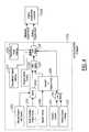
- FIG. 2shows a block diagram of one embodiment of the controller 12 of FIG. 1 .
- FIG. 2shows a manual transmission application wherein arbitration takes place between at least two different control variables. Specifically, driver demand and speed control are arbitrated in the engine speed domain, and the resulting desired engine speed is then arbitrated with traction control requirements in either the torque, acceleration, or speed domain.
- the driver demanded engine accelerationis determined by known methods such as the pedal position input.
- the conversion from driver demand to engine accelerationwill typically be a function of engine speed and inferred or measured driveline ratio in addition to the pedal position.
- the desired engine accelerationis integrated with respect to time to generate a desired engine speed value.
- a desired engine idle speedis also determined in block 104 which represents a minimum engine speed for the engine operating conditions.
- the selection mechanism 106a new target engine speed is determined based on the idle speed request from block 104 and the driver demand from block 100 .
- selection mechanism 106will select the maximum engine speed as between the desired idle speed and the driver demand.
- the selection mechanismis formed such that no “dead pedal” feel exists and any driver demand from an idle condition results in an increase in scheduled engine speed and resulting change in actual engine speed.
- a desired vehicle speed from the speed control system 108will also be generated.
- a desired vehicle speedis translated into a desired engine speed in block 110 by way of the measured or inferred transmission gear ratio.
- the resulting engine speedis then arbitrated with the engine speed in the selection arbitration block 112 with the engine speed resulting from the selection mechanism 106 .
- the greater of the engine speed requests from the driver demand and speed control systemwill be selected in block 112 .
- the resulting engine speed value from arbitration block 112is then constrained by vehicle engine and transmission speed limits.
- Vehicle speed limitingis determined in block 114 and is again converted to an engine speed limit associated therewith in block 110 . This value is then passed along to the arbitration block 116 .
- an engine speed limit value from block 118is also used to constrain the desired engine speed value resulting from the driver demand or speed control systems.
- the systemmay also include integrated transmission speed protection in block 120 , in which case, the transmission speed limit is applied as a clip to the engine speed limit request 118 .
- Engine speed controller 122can be PID controller which receives as an input a measured engine speed and outputs a desired airflow, fueling rate, valve timing and spark timing in the case of a gasoline engine to achieve the desired engine speed. In the case of gaseous-fueled engine, fuel flow and timing can also be controlled to modify the engine output.
- the controller 122also accommodates other system constraints as received from the torque domain 124 .
- the controller 122determines the valve timing, fuel and spark control target values which result in the desired engine output speed. These values are generated by known methods during engine mapping and calibration for the particular engine configuration under consideration.
- the desired spark advance (SA)can be determined.
- the corresponding valve timing commandis determined as a function of the relative fuel-air ratio (AFR), the manifold absolute pressure (MAP), and intake mass airflow (MAF).
- AFRrelative fuel-air ratio
- MAPmanifold absolute pressure
- MAFintake mass airflow
- a fuel commandis generated to achieve the desired engine output torque or speed as a function of the fuel rail temperature and pressure.
- the determined valve, fuel and spark control target valuesare arbitrated to optimize the engine operation for the current running conditions.
- the desired engine output speed or torquemay be realized by operating the engine as a CI engine with throttleless airflow whereby the engine torque is regulated with only the fuel command and spark angle.
- the wide flammability range of hydrogen fuelcan be more fully utilized allowing the engine to run extremely lean during low torque demand situations.
- the throttleless airflow compression in a CI engine operationhas the advantages of improved fuel economy, minimized engine output emissions and minimized engine pumping losses.
- Torque domain restraints on the engine speedinclude a maximum torque value to prevent wheel slip as determined by the traction control system 126 , and any torque-based transmission requirements in control block 128 . These torque-based constraints are then clipped in block 130 and communicated to the engine speed controller 122 . The engine speed controller 122 , in turn, limits the engine output according to the torque-based constraints.
- the traction control system and transmission limitingcan be derived in terms of an engine speed or engine acceleration and the resulting constraint arbitrated against the desired engine speed to control the engine accordingly.
- FIG. 3shows a block diagram of another embodiment of the controller 12 of FIG. 1 .
- FIG. 3shows an automatic transmission application wherein arbitration takes place between at least two different control variables. Specifically, driver demand and speed control are arbitrated in the engine speed domain, and the resulting desired engine speed is then arbitrated with traction control requirements in either the torque, acceleration, or speed domain.
- the driver demanded vehicle accelerationis determined by known methods such as a pedal position input. This is applicable when the transmission is engaged in gear.
- the conversion from driver demand to vehicle accelerationwill typically be a function of vehicle speed and inferred or measured driveline ratio in addition to the accelerator pedal position.
- the desired vehicle accelerationis integrated with respect to time to generate a desired road speed value. If active, a desired vehicle speed from the speed control system 154 will also be generated.
- the systemalso includes vehicle speed limiting in block 156 which acts as a clip to ensure that the requested vehicle speed does not exceed a maximum allowable value.
- These valuesare arbitrated in block 158 and a selection is made of the most appropriate value of desired road speed from among the in-gear driver demand, speed control system, and speed limiting system.
- the desired road speed or accelerationcan be used as a measure of driver demand as shown in block 160 .
- the desired vehicle speedis then converted in block 162 to an equivalent engine speed based on the measured or inferred transmission ratio.
- a corresponding in-neutral driver demand engine speed accelerationis determined in block 164 and is translated in block 166 to an equivalent in neutral engine speed demand.
- the selection mechanism 168selects a new value of target engine speed based upon the idle engine speed request from block 170 , the converted vehicle speed request from block 162 , and the in-neutral driver request from block 166 .
- the selection mechanism 168is formed such that no “dead pedal” feel exists in any driver demand from an idle condition results in an increase in scheduled engine speed and resulting change in actual engine speed.
- the resulting engine speed value from arbitration block 168is then constrained by an engine speed limit value from block 172 .
- the systemmay also include integrated transmission speed protection in block 174 , in which case, the transmission speed limit value is also applied as a clip to the engine speed limit request 172 .
- Arbitration block 176acts to constrain the desired engine speed value from the driver demand and speed control systems by the engine speed limit and transmission speed limit values.
- Engine speed controller 182can be PID controller which receives as an input in measured engine speed and outputs a desired valve timing, fueling rate, and spark timing in the case of a gasoline engine to achieve the desired engine speed. Fuel flow in the case of a gaseous-fueled engine may also be controlled to modify the engine output.
- the controller 122determines the valve timing, fuel and spark control target values which result in the desired engine output speed. These values are generated by known methods during engine mapping and calibration for the particular engine configuration under consideration.
- the controller 182also accommodates other system constraints as received from the torque domain 184 .
- Torque domain restraints on the engine speedinclude a maximum torque value to prevent wheel slip as determined by the traction control system 186 , and any torque-based transmission requirements in control block 188 . These torque-based constraints are then clipped in block 190 and communicated to the engine speed controller 182 . The engine speed controller 182 , in turn, limits the engine output according to the torque-based constraints.
- the traction control system and transmission limitingcan be derived in terms of an engine speed or engine acceleration, and the resulting constraint arbitrated against the desired engine speed to control the engine accordingly.
- FIG. 4shows a block diagram of another embodiment of the controller 12 of FIG. 1 .
- FIG. 4shows a manual transmission application wherein arbitration takes place between the driver demand, speed control, and traction control systems in the engine acceleration domain.
- the driver demanded engine speed accelerationis determined by, for example, the pedal position input.
- the conversion from pedal position input to desired engine speed accelerationwill typically be a function of engine speed and inferred or measured driveline ratio in addition to the pedal position input.
- a desired engine acceleration request to maintain the engine idle at its predetermined valueis also determined in block 202 .
- a new target engine speed accelerationis determined based upon the idle engine speed acceleration request from block 202 and the driver demanded engine speed acceleration request from block 200 .
- the selection mechanism 204will select the maximum engine speed acceleration as between the idle speed request and driver demand.
- the selection mechanism 204is formed such that no “dead pedal” feel exists and any driver demand from an idle condition results in an increase in scheduled engine speed acceleration and resulting change in actual engine speed.
- a desired vehicle speed acceleration from the speed control system 206will also be generated.
- the desired vehicle speed accelerationis translated to a desired engine speed acceleration in block 208 by way of the measured or inferred transmission gear ratio.
- the resulting desired engine accelerationis then arbitrated in block 210 with the engine acceleration request from selection block 204 .
- This systemalso includes vehicle speed limiting in block 212 and traction control system 214 both of which generate vehicle speed acceleration limits, the lowest one of which is selected in block 216 .
- the resulting valueis again converted from a vehicle acceleration value to an engine acceleration value in block 208 and communicated to arbitration block 218 .
- the systemalso includes engine acceleration speed limiting 220 , and integrated transmission speed protection 222 as well as acceleration-based transmission torque truncation 224 . All of these values which act to limit the engine acceleration are also communicated to the arbitration block 218 , wherein the received values are arbitrated with the driver demand and speed control resulting engine acceleration value to produce a final desired engine acceleration value.
- the desired engine acceleration value as derived from the acceleration domain 226is then communicated to the engine acceleration controller 228 .
- the engine acceleration controller 228is preferably a PID controller which receives as an input a measured engine acceleration value and outputs a desired airflow, fueling rate, and spark timing in the case of a gasoline engine to achieve the desired acceleration value.
- FIG. 5shows a block diagram of another embodiment of the controller 12 of FIG. 1 .
- FIG. 5shows an automatic transmission application wherein arbitration takes place in the acceleration domain 240 .
- the driver demanded vehicle accelerationis determined when the transmission is engaged.
- the conversion from the driver demand to a desired vehicle accelerationwill typically be a function of vehicle speed and the inferred or measured driveline ratio in addition to the accelerator pedal position.
- a desired vehicle speed acceleration from the speed control system 244will also be generated.
- this systemalso includes vehicle speed limiting 246 and traction control system 248 which each generate vehicle acceleration limit values.
- the resulting vehicle acceleration valuesare arbitrated in block 250 .
- the desired vehicle acceleration from arbitration block 250can be used as a measure of driver demand in block 252 .
- the desired vehicle acceleration value from arbitration block 250is then converted to an equivalent engine acceleration value in block 254 based on the measured or inferred transmission ratio. If the transmission is not in gear, an in-neutral driver demand engine acceleration request is determined in block 256 .
- a new value of target engine accelerationis determined based upon the idle engine acceleration request 260 , the converted vehicle acceleration request 254 , and the in-neutral driver demand 256 .
- the selection mechanism 258is formed such that no “dead pedal” feel exists and any driver demand from an idle condition results in an increase in scheduled engine speed acceleration and a resulting change in actual engine speed.
- the system of FIG. 5also includes engine speed limiting 262 , transmission speed limiting 264 , and acceleration-based transmission torque truncation 266 . These clips are then applied in arbitration block 268 so as to ensure that the requested engine acceleration does not exceed any maximum allowable values.
- the resulting desired engine accelerationis communicated to the engine acceleration controller 270 .
- Engine acceleration controller 270can be PID controller which receives as an input a measured engine acceleration and outputs a desired valve timing, fueling rate, and spark timing in the case of a gasoline engine to achieve the desired engine acceleration. Fuel flow and timing in the case of a gaseous-fueled engine can also be controlled to modify the engine output.
- the final desired engine acceleration valuecan also be integrated to be put in the speed domain and a controller 270 can use feedback on the measured engine speed to achieve the desired engine speed.
Landscapes
- Engineering & Computer Science (AREA)
- Chemical & Material Sciences (AREA)
- Combustion & Propulsion (AREA)
- Mechanical Engineering (AREA)
- Transportation (AREA)
- General Engineering & Computer Science (AREA)
- Control Of Vehicle Engines Or Engines For Specific Uses (AREA)
- Electrical Control Of Air Or Fuel Supplied To Internal-Combustion Engine (AREA)
Abstract
Description
Claims (16)
Priority Applications (1)
| Application Number | Priority Date | Filing Date | Title |
|---|---|---|---|
| US10/034,685US6554091B2 (en) | 2000-09-08 | 2001-12-28 | Engine output controller |
Applications Claiming Priority (2)
| Application Number | Priority Date | Filing Date | Title |
|---|---|---|---|
| US09/657,877US6347680B1 (en) | 2000-09-08 | 2000-09-08 | Engine output controller |
| US10/034,685US6554091B2 (en) | 2000-09-08 | 2001-12-28 | Engine output controller |
Related Parent Applications (1)
| Application Number | Title | Priority Date | Filing Date |
|---|---|---|---|
| US09/657,877Continuation-In-PartUS6347680B1 (en) | 2000-09-08 | 2000-09-08 | Engine output controller |
Publications (2)
| Publication Number | Publication Date |
|---|---|
| US20020056581A1 US20020056581A1 (en) | 2002-05-16 |
| US6554091B2true US6554091B2 (en) | 2003-04-29 |
Family
ID=46278631
Family Applications (1)
| Application Number | Title | Priority Date | Filing Date |
|---|---|---|---|
| US10/034,685Expired - Fee RelatedUS6554091B2 (en) | 2000-09-08 | 2001-12-28 | Engine output controller |
Country Status (1)
| Country | Link |
|---|---|
| US (1) | US6554091B2 (en) |
Cited By (8)
| Publication number | Priority date | Publication date | Assignee | Title |
|---|---|---|---|---|
| US20040107925A1 (en)* | 2002-11-21 | 2004-06-10 | Goichi Katayama | Control system for outboard motor |
| US7520263B1 (en)* | 2007-11-07 | 2009-04-21 | Hyundai Motor Company | Engine torque control apparatus and engine torque control method |
| US20110066344A1 (en)* | 2009-09-16 | 2011-03-17 | Denso Corporation | Apparatus for arbitrating plurality of control requests relating to automatic control of vehicle motion |
| US8370042B2 (en)* | 2007-07-11 | 2013-02-05 | Denso Corporation | Vehicle speed control device and method |
| US20130046454A1 (en)* | 2011-08-15 | 2013-02-21 | GM Global Technology Operations LLC | System and method for adjusting fuel mass for minimum fuel injector pulse widths in multiple fuel system engines |
| US9097224B2 (en) | 2011-08-15 | 2015-08-04 | GM Global Technology Operations LLC | Multi-fuel vehicle fuel control systems and methods |
| US9598067B2 (en) | 2012-08-24 | 2017-03-21 | Eaton Corporation | Control strategy for AWD connection and disconnection |
| US10203034B2 (en)* | 2015-10-07 | 2019-02-12 | Kawasaki Jukogyo Kabushiki Kaisha | Output control system |
Families Citing this family (7)
| Publication number | Priority date | Publication date | Assignee | Title |
|---|---|---|---|---|
| CA2572595C (en)* | 2006-01-26 | 2011-03-29 | Honda Motor Co., Ltd | Engine-driven work machine |
| US7707977B2 (en)* | 2006-10-18 | 2010-05-04 | Caterpillar Inc. | Variable valve performance detection strategy for internal combustion engine |
| US7877183B2 (en)* | 2007-11-30 | 2011-01-25 | Caterpillar Inc. | Power train control system with engine speed override |
| DE102008062210A1 (en)* | 2008-12-13 | 2010-06-17 | Man Nutzfahrzeuge Ag | Method for controlling an acceleration device for motor vehicles |
| FR3062833B1 (en)* | 2017-02-10 | 2019-04-05 | Peugeot Citroen Automobiles Sa | METHOD OF AUTONOMOUS DRIVING A MOTOR VEHICLE |
| DE102018207079A1 (en)* | 2018-05-07 | 2019-11-07 | Audi Ag | Method for controlling a drive motor in a motor vehicle |
| US11912135B2 (en) | 2021-03-24 | 2024-02-27 | Fca Us Llc | Battery electric vehicle accelerator pedal control based on user-selectable deceleration limit and driver intent |
Citations (25)
| Publication number | Priority date | Publication date | Assignee | Title |
|---|---|---|---|---|
| US4651684A (en) | 1982-09-10 | 1987-03-24 | Mazda Motor Corporation | Valve timing control system for internal combustion engine |
| US4714864A (en) | 1985-05-27 | 1987-12-22 | Nippondenso Co., Ltd. | Throttle control device for vehicles |
| US4984167A (en) | 1988-02-05 | 1991-01-08 | Hitachi, Ltd. | Control apparatus and method for an internal combustion engine |
| US5022357A (en) | 1988-12-28 | 1991-06-11 | Isuzu Motors Limited | Control system for internal combustion engine |
| US5078109A (en) | 1989-01-31 | 1992-01-07 | Mitsubishi Jidosha Kogyo Kabushiki Kaisha | Engine output controlling method |
| US5088043A (en) | 1988-11-14 | 1992-02-11 | Mitsubishi Jidosha Kogyo Kabushiki Kaisha | Engine controlling system for vehicle |
| US5197008A (en) | 1990-01-25 | 1993-03-23 | Mitsubishi Jidosha Kokyo Kabushiki Kaisha | System for controlling the output power of a motor vehicle |
| US5243526A (en) | 1990-05-18 | 1993-09-07 | Mitsubishi Jidosha Kogyo Kabushiki Kaisha | Output control apparatus for vehicle |
| US5284116A (en) | 1988-07-29 | 1994-02-08 | North American Philips Corporation | Vehicle management computer |
| US5297048A (en) | 1992-09-21 | 1994-03-22 | Automotive Integrated Electronics Co., Inc. | Angular position extrapolation of a rotating crankshaft corrected for crankshaft acceleration and deceleration |
| US5400865A (en) | 1989-01-31 | 1995-03-28 | Mitsubishi Jidosha Kogyo Kabushiki Kaisha | Engine output control apparatus |
| US5541843A (en) | 1992-12-25 | 1996-07-30 | Zexel Corporation | Engine output control device for vehicles |
| US5588411A (en) | 1995-01-18 | 1996-12-31 | Meta Motoren- Und Energie-Technik Gmbh | Method for controlling an internal combustion engine with external ignition system and with a fuel injection system |
| US5615655A (en)* | 1994-06-29 | 1997-04-01 | Honda Giken Kogyo K.K. | Control system for internal combustion engines |
| US5623412A (en) | 1993-10-12 | 1997-04-22 | Institut Francais Du Petrole | Instantaneous data acquisition and processing system for internal-combustion engine control |
| US5625558A (en) | 1990-11-29 | 1997-04-29 | Mitsubishi Jidosha Kogyo Kabushiki Kaisha | Drive-by-wire vehicle engine output control system |
| US5668727A (en) | 1995-04-28 | 1997-09-16 | General Motors Corporations | Powertrain torque control method |
| US5996560A (en) | 1992-03-23 | 1999-12-07 | Ford Motor Company | Unthrottled engine operation with a heated air cycle |
| US6155217A (en) | 1997-05-30 | 2000-12-05 | Hitachi, Ltd. | Control method of an internal combustion engine |
| US6199006B1 (en)* | 1998-04-29 | 2001-03-06 | Deere & Company | Control system for internal combustion engines |
| US6278933B1 (en) | 2000-04-28 | 2001-08-21 | Ford Global Technologies, Inc. | Rapid transient torque management in DISI engines |
| US6286482B1 (en) | 1996-08-23 | 2001-09-11 | Cummins Engine Company, Inc. | Premixed charge compression ignition engine with optimal combustion control |
| US6304809B1 (en) | 2000-03-21 | 2001-10-16 | Ford Global Technologies, Inc. | Engine control monitor for vehicle equipped with engine and transmission |
| US6330873B1 (en)* | 1993-08-27 | 2001-12-18 | Detroit Diesel Corporation | Method for engine control |
| US6379281B1 (en)* | 2000-09-08 | 2002-04-30 | Visteon Global Technologies, Inc. | Engine output controller |
- 2001
- 2001-12-28USUS10/034,685patent/US6554091B2/ennot_activeExpired - Fee Related
Patent Citations (25)
| Publication number | Priority date | Publication date | Assignee | Title |
|---|---|---|---|---|
| US4651684A (en) | 1982-09-10 | 1987-03-24 | Mazda Motor Corporation | Valve timing control system for internal combustion engine |
| US4714864A (en) | 1985-05-27 | 1987-12-22 | Nippondenso Co., Ltd. | Throttle control device for vehicles |
| US4984167A (en) | 1988-02-05 | 1991-01-08 | Hitachi, Ltd. | Control apparatus and method for an internal combustion engine |
| US5284116A (en) | 1988-07-29 | 1994-02-08 | North American Philips Corporation | Vehicle management computer |
| US5088043A (en) | 1988-11-14 | 1992-02-11 | Mitsubishi Jidosha Kogyo Kabushiki Kaisha | Engine controlling system for vehicle |
| US5022357A (en) | 1988-12-28 | 1991-06-11 | Isuzu Motors Limited | Control system for internal combustion engine |
| US5400865A (en) | 1989-01-31 | 1995-03-28 | Mitsubishi Jidosha Kogyo Kabushiki Kaisha | Engine output control apparatus |
| US5078109A (en) | 1989-01-31 | 1992-01-07 | Mitsubishi Jidosha Kogyo Kabushiki Kaisha | Engine output controlling method |
| US5197008A (en) | 1990-01-25 | 1993-03-23 | Mitsubishi Jidosha Kokyo Kabushiki Kaisha | System for controlling the output power of a motor vehicle |
| US5243526A (en) | 1990-05-18 | 1993-09-07 | Mitsubishi Jidosha Kogyo Kabushiki Kaisha | Output control apparatus for vehicle |
| US5625558A (en) | 1990-11-29 | 1997-04-29 | Mitsubishi Jidosha Kogyo Kabushiki Kaisha | Drive-by-wire vehicle engine output control system |
| US5996560A (en) | 1992-03-23 | 1999-12-07 | Ford Motor Company | Unthrottled engine operation with a heated air cycle |
| US5297048A (en) | 1992-09-21 | 1994-03-22 | Automotive Integrated Electronics Co., Inc. | Angular position extrapolation of a rotating crankshaft corrected for crankshaft acceleration and deceleration |
| US5541843A (en) | 1992-12-25 | 1996-07-30 | Zexel Corporation | Engine output control device for vehicles |
| US6330873B1 (en)* | 1993-08-27 | 2001-12-18 | Detroit Diesel Corporation | Method for engine control |
| US5623412A (en) | 1993-10-12 | 1997-04-22 | Institut Francais Du Petrole | Instantaneous data acquisition and processing system for internal-combustion engine control |
| US5615655A (en)* | 1994-06-29 | 1997-04-01 | Honda Giken Kogyo K.K. | Control system for internal combustion engines |
| US5588411A (en) | 1995-01-18 | 1996-12-31 | Meta Motoren- Und Energie-Technik Gmbh | Method for controlling an internal combustion engine with external ignition system and with a fuel injection system |
| US5668727A (en) | 1995-04-28 | 1997-09-16 | General Motors Corporations | Powertrain torque control method |
| US6286482B1 (en) | 1996-08-23 | 2001-09-11 | Cummins Engine Company, Inc. | Premixed charge compression ignition engine with optimal combustion control |
| US6155217A (en) | 1997-05-30 | 2000-12-05 | Hitachi, Ltd. | Control method of an internal combustion engine |
| US6199006B1 (en)* | 1998-04-29 | 2001-03-06 | Deere & Company | Control system for internal combustion engines |
| US6304809B1 (en) | 2000-03-21 | 2001-10-16 | Ford Global Technologies, Inc. | Engine control monitor for vehicle equipped with engine and transmission |
| US6278933B1 (en) | 2000-04-28 | 2001-08-21 | Ford Global Technologies, Inc. | Rapid transient torque management in DISI engines |
| US6379281B1 (en)* | 2000-09-08 | 2002-04-30 | Visteon Global Technologies, Inc. | Engine output controller |
Cited By (12)
| Publication number | Priority date | Publication date | Assignee | Title |
|---|---|---|---|---|
| US20040107925A1 (en)* | 2002-11-21 | 2004-06-10 | Goichi Katayama | Control system for outboard motor |
| US7055473B2 (en)* | 2002-11-21 | 2006-06-06 | Yamaha Marine Kabushiki Kaisha | Control system for outboard motor |
| US8370042B2 (en)* | 2007-07-11 | 2013-02-05 | Denso Corporation | Vehicle speed control device and method |
| US7520263B1 (en)* | 2007-11-07 | 2009-04-21 | Hyundai Motor Company | Engine torque control apparatus and engine torque control method |
| US20090114187A1 (en)* | 2007-11-07 | 2009-05-07 | Hyung Kee Kim | Engine torque control apparatus and engine torque control method |
| US20110066344A1 (en)* | 2009-09-16 | 2011-03-17 | Denso Corporation | Apparatus for arbitrating plurality of control requests relating to automatic control of vehicle motion |
| US8332118B2 (en)* | 2009-09-16 | 2012-12-11 | Denso Corporation | Apparatus for arbitrating plurality of control requests relating to automatic control of vehicle motion |
| US20130046454A1 (en)* | 2011-08-15 | 2013-02-21 | GM Global Technology Operations LLC | System and method for adjusting fuel mass for minimum fuel injector pulse widths in multiple fuel system engines |
| US9097224B2 (en) | 2011-08-15 | 2015-08-04 | GM Global Technology Operations LLC | Multi-fuel vehicle fuel control systems and methods |
| US9169789B2 (en)* | 2011-08-15 | 2015-10-27 | GM Global Technology Operations LLC | System and method for adjusting fuel mass for minimum fuel injector pulse widths in multiple fuel system engines |
| US9598067B2 (en) | 2012-08-24 | 2017-03-21 | Eaton Corporation | Control strategy for AWD connection and disconnection |
| US10203034B2 (en)* | 2015-10-07 | 2019-02-12 | Kawasaki Jukogyo Kabushiki Kaisha | Output control system |
Also Published As
| Publication number | Publication date |
|---|---|
| US20020056581A1 (en) | 2002-05-16 |
Similar Documents
| Publication | Publication Date | Title |
|---|---|---|
| US6347680B1 (en) | Engine output controller | |
| US6668804B2 (en) | Control system and method for a bi-fuel engine | |
| US6554091B2 (en) | Engine output controller | |
| US20020185086A1 (en) | Method of and system for fuel supply for an internal combustion engine | |
| US6990947B2 (en) | Homogeneous charge compression ignition engine and method for operating homogeneous charge compression ignition engine | |
| CA2295300C (en) | Controlling the injection in a fuel injection system selectively operable with gasoline or fuel gas | |
| KR100284463B1 (en) | Engine throttle control | |
| EP1024275A2 (en) | Fuel limiting method in diesel engines having exhaust gas recirculation | |
| US20050235952A1 (en) | Homogeneous charge compression ignition engine and method for operating homogeneous charge compression ignition engine | |
| US6237329B1 (en) | Combustion controller for lean burn engines | |
| JP2003513191A (en) | Method of controlling cooling water temperature of an automobile having an internal combustion engine | |
| CN105074182B (en) | The control of internal combustion engine | |
| US5720266A (en) | Control system for a gaseous fuel internal combustion engine utilizing PID gain scheduling parameters | |
| US6512983B1 (en) | Method for determining the controller output for controlling fuel injection engines | |
| US6305347B1 (en) | Monitor for lean capable engine | |
| EP1643110B1 (en) | Internal combustion engine | |
| US6386174B1 (en) | Method for operating an internal combustion engine | |
| US6263856B1 (en) | Powertrain output monitor | |
| GB2328294A (en) | Controlling exhaust gas return rate in an internal combustion engine | |
| US6295967B1 (en) | Powertrain output monitor | |
| US6625974B1 (en) | Method for operating an internal combustion engine | |
| US6805091B2 (en) | Method for determining the fuel content of the regeneration gas in an internal combustion engine comprising direct fuel-injection with shift operation | |
| US6508227B2 (en) | Method of operating an internal combustion engine | |
| US6286305B1 (en) | Model based enrichment for exhaust temperature protection | |
| JP2002221037A (en) | In-cylinder injection gas-fueled internal combustion engine |
Legal Events
| Date | Code | Title | Description |
|---|---|---|---|
| REMI | Maintenance fee reminder mailed | ||
| LAPS | Lapse for failure to pay maintenance fees | ||
| STCH | Information on status: patent discontinuation | Free format text:PATENT EXPIRED DUE TO NONPAYMENT OF MAINTENANCE FEES UNDER 37 CFR 1.362 | |
| FP | Expired due to failure to pay maintenance fee | Effective date:20070429 | |
| AS | Assignment | Owner name:JPMORGAN CHASE BANK, N.A., AS ADMINISTRATIVE AGENT Free format text:SECURITY AGREEMENT;ASSIGNOR:VISTEON GLOBAL TECHNOLOGIES, INC.;REEL/FRAME:020497/0733 Effective date:20060613 | |
| AS | Assignment | Owner name:JPMORGAN CHASE BANK, TEXAS Free format text:SECURITY INTEREST;ASSIGNOR:VISTEON GLOBAL TECHNOLOGIES, INC.;REEL/FRAME:022368/0001 Effective date:20060814 Owner name:JPMORGAN CHASE BANK,TEXAS Free format text:SECURITY INTEREST;ASSIGNOR:VISTEON GLOBAL TECHNOLOGIES, INC.;REEL/FRAME:022368/0001 Effective date:20060814 | |
| AS | Assignment | Owner name:WILMINGTON TRUST FSB, AS ADMINISTRATIVE AGENT, MIN Free format text:ASSIGNMENT OF SECURITY INTEREST IN PATENTS;ASSIGNOR:JPMORGAN CHASE BANK, N.A., AS ADMINISTRATIVE AGENT;REEL/FRAME:022575/0186 Effective date:20090415 Owner name:WILMINGTON TRUST FSB, AS ADMINISTRATIVE AGENT,MINN Free format text:ASSIGNMENT OF SECURITY INTEREST IN PATENTS;ASSIGNOR:JPMORGAN CHASE BANK, N.A., AS ADMINISTRATIVE AGENT;REEL/FRAME:022575/0186 Effective date:20090415 | |
| AS | Assignment | Owner name:VISTEON GLOBAL TECHNOLOGIES, INC., MICHIGAN Free format text:RELEASE BY SECURED PARTY AGAINST SECURITY INTEREST IN PATENTS RECORDED AT REEL 022575 FRAME 0186;ASSIGNOR:WILMINGTON TRUST FSB, AS ADMINISTRATIVE AGENT;REEL/FRAME:025105/0201 Effective date:20101001 |