US6552888B2 - Safety electrical outlet with logic control circuit - Google Patents
Safety electrical outlet with logic control circuitDownload PDFInfo
- Publication number
- US6552888B2 US6552888B2US09/767,067US76706701AUS6552888B2US 6552888 B2US6552888 B2US 6552888B2US 76706701 AUS76706701 AUS 76706701AUS 6552888 B2US6552888 B2US 6552888B2
- Authority
- US
- United States
- Prior art keywords
- outlet
- sensor
- source
- contact friction
- radiation
- Prior art date
- Legal status (The legal status is an assumption and is not a legal conclusion. Google has not performed a legal analysis and makes no representation as to the accuracy of the status listed.)
- Expired - Lifetime, expires
Links
- 238000003780insertionMethods0.000claimsabstractdescription37
- 230000037431insertionEffects0.000claimsabstractdescription37
- 230000005855radiationEffects0.000claimsdescription64
- 238000012544monitoring processMethods0.000claimsdescription33
- 239000000463materialSubstances0.000claimsdescription13
- 238000000034methodMethods0.000claimsdescription8
- 239000000835fiberSubstances0.000claimsdescription5
- CJOBVZJTOIVNNF-UHFFFAOYSA-Ncadmium sulfideChemical compound[Cd]=SCJOBVZJTOIVNNF-UHFFFAOYSA-N0.000claimsdescription4
- 229910052980cadmium sulfideInorganic materials0.000claimsdescription4
- 238000001514detection methodMethods0.000claimsdescription4
- 230000007935neutral effectEffects0.000description11
- 238000012360testing methodMethods0.000description10
- 238000013021overheatingMethods0.000description6
- 230000035939shockEffects0.000description3
- 230000011664signalingEffects0.000description3
- 230000004397blinkingEffects0.000description2
- 230000006378damageEffects0.000description2
- 238000010586diagramMethods0.000description2
- 238000005286illuminationMethods0.000description2
- 238000006467substitution reactionMethods0.000description2
- 239000003990capacitorSubstances0.000description1
- 230000005465channelingEffects0.000description1
- 238000002485combustion reactionMethods0.000description1
- 230000007797corrosionEffects0.000description1
- 238000005260corrosionMethods0.000description1
- 230000002950deficientEffects0.000description1
- 230000009977dual effectEffects0.000description1
- 230000005611electricityEffects0.000description1
- 238000009413insulationMethods0.000description1
- JEIPFZHSYJVQDO-UHFFFAOYSA-Niron(III) oxideInorganic materialsO=[Fe]O[Fe]=OJEIPFZHSYJVQDO-UHFFFAOYSA-N0.000description1
- 239000002184metalSubstances0.000description1
- 230000001681protective effectEffects0.000description1
- 230000001960triggered effectEffects0.000description1
Images


Classifications
- H—ELECTRICITY
- H02—GENERATION; CONVERSION OR DISTRIBUTION OF ELECTRIC POWER
- H02H—EMERGENCY PROTECTIVE CIRCUIT ARRANGEMENTS
- H02H3/00—Emergency protective circuit arrangements for automatic disconnection directly responsive to an undesired change from normal electric working condition with or without subsequent reconnection ; integrated protection
- H02H3/12—Emergency protective circuit arrangements for automatic disconnection directly responsive to an undesired change from normal electric working condition with or without subsequent reconnection ; integrated protection responsive to underload or no-load
- H—ELECTRICITY
- H01—ELECTRIC ELEMENTS
- H01R—ELECTRICALLY-CONDUCTIVE CONNECTIONS; STRUCTURAL ASSOCIATIONS OF A PLURALITY OF MUTUALLY-INSULATED ELECTRICAL CONNECTING ELEMENTS; COUPLING DEVICES; CURRENT COLLECTORS
- H01R13/00—Details of coupling devices of the kinds covered by groups H01R12/70 or H01R24/00 - H01R33/00
- H01R13/66—Structural association with built-in electrical component
- H01R13/70—Structural association with built-in electrical component with built-in switch
- H01R13/713—Structural association with built-in electrical component with built-in switch the switch being a safety switch
- H—ELECTRICITY
- H01—ELECTRIC ELEMENTS
- H01R—ELECTRICALLY-CONDUCTIVE CONNECTIONS; STRUCTURAL ASSOCIATIONS OF A PLURALITY OF MUTUALLY-INSULATED ELECTRICAL CONNECTING ELEMENTS; COUPLING DEVICES; CURRENT COLLECTORS
- H01R13/00—Details of coupling devices of the kinds covered by groups H01R12/70 or H01R24/00 - H01R33/00
- H01R13/648—Protective earth or shield arrangements on coupling devices, e.g. anti-static shielding
- H01R13/652—Protective earth or shield arrangements on coupling devices, e.g. anti-static shielding with earth pin, blade or socket
- H—ELECTRICITY
- H01—ELECTRIC ELEMENTS
- H01R—ELECTRICALLY-CONDUCTIVE CONNECTIONS; STRUCTURAL ASSOCIATIONS OF A PLURALITY OF MUTUALLY-INSULATED ELECTRICAL CONNECTING ELEMENTS; COUPLING DEVICES; CURRENT COLLECTORS
- H01R2103/00—Two poles
- H—ELECTRICITY
- H01—ELECTRIC ELEMENTS
- H01R—ELECTRICALLY-CONDUCTIVE CONNECTIONS; STRUCTURAL ASSOCIATIONS OF A PLURALITY OF MUTUALLY-INSULATED ELECTRICAL CONNECTING ELEMENTS; COUPLING DEVICES; CURRENT COLLECTORS
- H01R24/00—Two-part coupling devices, or either of their cooperating parts, characterised by their overall structure
- H01R24/76—Two-part coupling devices, or either of their cooperating parts, characterised by their overall structure with sockets, clips or analogous contacts and secured to apparatus or structure, e.g. to a wall
- H01R24/78—Two-part coupling devices, or either of their cooperating parts, characterised by their overall structure with sockets, clips or analogous contacts and secured to apparatus or structure, e.g. to a wall with additional earth or shield contacts
- H—ELECTRICITY
- H02—GENERATION; CONVERSION OR DISTRIBUTION OF ELECTRIC POWER
- H02H—EMERGENCY PROTECTIVE CIRCUIT ARRANGEMENTS
- H02H5/00—Emergency protective circuit arrangements for automatic disconnection directly responsive to an undesired change from normal non-electric working conditions with or without subsequent reconnection
- H02H5/04—Emergency protective circuit arrangements for automatic disconnection directly responsive to an undesired change from normal non-electric working conditions with or without subsequent reconnection responsive to abnormal temperature
- H02H5/042—Emergency protective circuit arrangements for automatic disconnection directly responsive to an undesired change from normal non-electric working conditions with or without subsequent reconnection responsive to abnormal temperature using temperature dependent resistors
Definitions
- the present inventionrelates to a logic control device that can be integrated into any double or single household or commercial electrical outlet. It controls the outlet and transforms it into a safe and “smart” outlet.
- the devicecan also be integrated into an extension cord, adapter or placed over an outlet as a cover plate.
- the logic circuit in the smart outletinstantly senses the state and condition of itself and the physical and electrical changes that occur.
- ground fault circuitry interrupterseither interrupt the power until the electric circuit is restored to normal, for example, by manually resetting an electro-mechanical breaker. Some circuits automatically power-up when normal power resumes. Conveniently, such ground fault circuit interrupters are wired, for example directly into the tool, device or appliance, or it is molded into the cord designated for the tool or device line. Ground fault interrupters are developed to sense minute imbalances in a circuit by current leakage to ground.
- Standard electrical built-in outlets either in the home or in an industrial settingmay be also equipped with a ground fault circuit interrupter, a GFCI.
- GFCI devicesprovide a test and reset function which both work together so that a tripped GFCI cannot be reset if the GFCI circuit no longer provides ground fault protection.
- the test buttoncan still be operated in the event of an open neutral condition even though the GFCI circuit is no longer powered.
- a built-in line load reversal featurealso prevents the GFCI from resetting if the load and the conditions are mistakenly reversed.
- the GFCI receptacle facewill be live, but there will be no power delivered to devices downstream, indicating a load reversal.
- An intelligent circuit interrupt systemis disclosed, for example, in U.S. Pat. No. 6,111,733 in which an intelligent circuit is electrically connected between an AC source and a load for interrupting a flow of AC from the source to the load upon detection of an interrupt condition.
- a circuit interrupter electrically connected to phase and neutral terminals of the AC sourcedefines the interrupt condition.
- a relay switch with a relay coil and phase and neutral contactsis included such that line and load ends of the phase contact are electrically connected, respectively, between the interrupt means load side phase port and a phase terminal of the load. Line and load ends of the neutral contact are electrically connected, respectively, between the interrupt neutral port and a neutral terminal of the load.
- the relay coilis electrically coupled between load sides of said phase and neutral contacts for controlling the contacts in response to the interrupt signal.
- An open-contact miswiring detectoris electrically connected to one of the phase and neutral contacts for detecting a miswiring condition when the contacts are in an open state
- a closed-contact miswiring detectoris electrically connected to the OCMD and to one of the neutral and phase contacts for detecting a miswiring condition when the contacts are in a closed state.
- a timing signal generatorgenerates system timing signals.
- a test circuitelectrically coupled to the interrupt means and the timing signal generator tests the interrupt means operability.
- An alarm circuitis electrically responsive to the test circuit, the timing signal generator, the OCMD and the CCMD for communicating an open-contact miswiring condition, a closed-contact miswiring condition, an operational failure condition, and a need for external testing condition.
- a power supplyis electrically connected between the load ends of the phase and neutral contacts, and to the timing signal generator.
- the intelligent circuitis mounted inside or alongside a standard electrical code-approved outlet box, such that the outlet itself can be installed in the same or similar manner as any outlet is installed.
- the outlet with the intelligent circuitis preferably a wall mount single or double outlet box and creates thereby a “smart outlet.”
- the smart outletdoes not alter normal operation of any appliance or device, and does not change or modify the normal flow of electricity or any of its characteristic. It operates at the rated voltage, amperage and frequency, for example, at 120Vac and 10Amp for residential use, or at 240Vac, 15 Amp for commercial use, either at 50 or 60 Hz.
- the smart outlet of the present inventionallows normal operation of any device or appliance plugged to the outlet directly or through an extension cord. It can be used with any standard on/off, a remote control unit or any other switching device.
- power supplies from household or industrial outletsdeliver power as soon as the device or appliance is plugged in or, power is always present and uninterrupted at the outlet, power or extension cord and appliance or device, except for an interruption within or at this device, yet in general all devices and appliances remain fully or partially powered, in particular power and extension cords.
- a smart outletWhen a smart outlet is used and the electrical plug of an electrical device or appliance is properly inserted, the device is initially always turned off. The logic circuit will sense this condition and the power will remain off, i.e., the smart outlet will not provide any power to the device or appliance. Only when the power switch of the device or appliance is turned on and the circuit is electrically completed, can the device or the appliance draw power and operate.
- the smart outletis designed such that it will shut off the power, when the circuit is interrupted (for example, the bulb is unscrewed or has burned out). The power will remain off until the electrical circuit is re-established, and the electrical device or appliance is turned on again.
- the smart outletis designed to continually monitors any or all of the designed functions, such as it monitors proper and full plug insertion, load presence, current load on the outlet and it senses the outlet temperature.
- a radiation sourcesuch as a light source, for example, an LED
- the light conducting means channelmay extend through the outlet perpendicularly to the slotted plug openings for the outlet contacts.
- a photo sensoris positioned at each end of the light conducting channel.
- the photo sensorsmay be cadmium-sulphide photo cells, photo diodes or photo transistors. When the blades of the plug are fully inserted into the slotted openings of the socket, the blades interrupt the radiation stream in the radiation conducting channels and the illumination of the photo sensors is interrupted.
- the photo sensorsare connected to a logic circuit that controls power to the outlet.
- the circuitryincludes logic means, such as an “AND” gate and/or appropriate software in a micro controller to sense that both photosensor are simultaneously substantially light blocked or un-illuminated which indicates a correct insertion. This insures that both blades are fully inserted into the outlet contacts.
- the softwarewill permit a relay in the circuit to close. Power can only reach the outlet contacts when the relay is closed. Thus, a broken plug, or a single wire, clip or other invalid object will not cause electric power to be applied to the outlet.
- the inventionalso contemplates to utilize as a radiation source a non-visible light LED i.e., ultra-violet radiation.
- This featureaddresses the problems of overloading outlets with too many appliances or devices, which causes overheating and potential fire.
- the load currentis measured by the voltage drop across a resistor positioned in the current path.
- This voltage dropis then amplified by a gain block, typically an op amp, integrated by a network, and then tested for magnitude by a comparator. If a current overload occurs, the output of the comparator will go high, thus signaling that event to the micro controller. This will engage a software routine to turn off a relay, and thus removing the line voltage from the socket.
- An indicator lightwill be turned on at this point, such as a red LED, showing that an overload has occurred.
- Another aspect of the inventionis to provide sensing the load presence and current load on the outlet.
- the monitoring of the load presencemakes it possible to only allow power to be present when a load is drawing a specified minimum amount of current. That is, a device or appliance which is turned off, will not draw current and thus, no voltage will be applied. This will also eliminate a major cause for electric shocks.
- the inventionmakes it possible to detect even a very small load, such as the load of an electric clock which draws only a few milliamperes.
- This featureis also particularly important as a child safety feature, because, as discussed above in conjunction with the monitoring of proper plug insertion, a child might insert a proper plug, having cut, open or raw wires extending from the plug, that is, the plug is not attached to any device. In such instance, the circuitry will not allow power to go to the outlet and, thus, the plug will not be under power.
- the inventionprovides for monitoring the temperature in the outlet. Changes in the temperature are observed. If the temperature deviates or exceeds a safe operating temperature, no power is provided to the outlet.
- This featurealone eliminates one of the major causes of electrical fires, since overheating of electrical outlets is one of a major fire hazards. Overheating is often caused by a defective plug, that is, a plug which is either physically damaged, rusty, or corroded. Rust, corrosion or dirt on the plug blades causes a high electrical resistance to exist between the blades of the plug and the outlet contacts. This high resistance causes a power loss and will raise the temperature of the outlet structure. Ultimately, the combustion temperature of the wall material or the insulation on the wiring may be reached, and a fire will occur.
- the present inventionprovides a temperature sensing means which interrupts the power supply to the device or appliance if the sensed temperature raises above a set temperature.
- a temperature sensing meanswhich interrupts the power supply to the device or appliance if the sensed temperature raises above a set temperature.
- Good electrical practicedictates that the outlet temperature should not rise higher than about 70° C. to 80° C., depending on the local code. However, this threshold can be set for any code mandated, or safe operating temperature.
- One embodiment for monitoring the outlet temperatureutilizes a thermistor, but any other device for sensing temperature may be used.
- the thermistoris preferably placed in close physical contact with the plastic body of the outlet structure, so that the thermistor temperature is approximately equal to the outlet temperature.
- the electrical resistance of a thermistorvaries inversely as a function of its temperature.
- electronic circuitrypreferably a comparator or a Schmitt trigger, the electrical resistance of the thermistor and hence its temperature, can be compared with an accurate internal reference.
- the outletprovides power to the appliances or devices connected to the outlet, either directly of via an extension cord. All monitoring is continuous, regardless of the appliance's state, and can work with almost any electrical appliance, device, machine or electrical motor.
- FIG. 1illustrates an overall block diagram of the invention
- FIG. 2illustrates a wall outlet and a plug, the wall outlet includes a board containing the logic circuit according to the invention
- FIG. 3illustrates an embodiment for temperature sensing and full and proper plug insertion
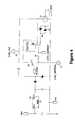
- FIG. 4illustrates a power line interface circuitry
- FIG. 5illustrates a temperature testing circuit
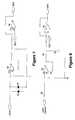
- FIG. 6illustrates the circuitry for testing proper plug insertion
- FIG. 7illustrates a circuitry for monitoring of load presence.
- FIG. 8illustrates a current load circuitry
- FIG. 9illustrates the circuitry including a microprocessor and indicator lights.
- FIG. 1illustrates an overall block diagram of the invention.
- the wall outlet 15represents a standard wall mounted outlet and may be a dual outlet, as shown in FIG. 2 .
- the outletmay include all functions of a ground fault interrupter, as is known in the prior art and which is not further described here.
- Physically associated with the wall outlet 15is a board 20 , for example a PCB board containing the circuitry for monitoring at least four conditions that need to conform in order for the outlet to provide power to any connected device or apparatus.
- the four monitored functionsare proper plug insertion 50 ; load presence monitoring 54 and current load monitoring 56 , as well as temperature sensing 52 in the outlet.
- Signals inputs from these four sensing or monitoring circuitsare analyzed by the micro processor 100 which in turn triggers an electrically controlled switch 40 , such as a relay, to provide or not provide power to the outlet 15 .
- the inputs of signals from these four sensing or monitoring circuitsare analyzed by the micro processor 100 , which in turn triggers the electrically controlled switch, relay 40 , to provide or not provide power to the outlet 15 .
- the microprocessormay also support an I/O port 110 for remote control addressing devices, such as computers and real time monitoring, networks or Internet. Accordingly, the electrically controlled switch may be triggered remotely, for example, in the event of a fire, not caused by electrical overheating of the circuit, the outlet may be turned off from a remote device. It is understood that the data for remote control have to be in digital format.
- FIG. 2illustrates a wall outlet 15 and a plug 30 with blades 32 and 34 .
- the wall outlet 15includes a board 20 containing the logic circuit according to the invention and two plug insertion openings 16 and 17 to receive the blades 32 and 34 from the plug.
- FIG. 3illustrates a top view of the outlet 15 with a temperature sensing and fall and proper plug insertion arrangement.
- the outlet 15shows the contact friction apertures 74 and 75 for receiving the blades of plug 30 .
- the radiation source 60is positioned substantially centrally between the contact friction apertures 74 and 75 and emits radiation which is detected by sensors 66 and 68 .
- the radiation source 60may be a light source, such as an LED and the sensors 66 and 68 may be photo sensors.
- the lighttravels through light channels 62 and 64 .
- the sensors 66 and 68are located on the outside wall of the contact friction apertures 74 and 75 .
- the friction apertureshave an opening adjacent to the sensors, Upon full and proper plug insertion, the channels are blocked off.
- the circuitryis designed to provide power to the outlet.
- a radiation source and radiation transmitting rodsas 62 and 64 , such as fiber optics rods.
- the radiation sourcemay be ultra violet or infrared radiation.
- Such embodimentwill deter potential errors that might occur when sun light would penetrate the plug openings 16 and 17 , as well as 74 and 75 .
- Such sunlightnight be misread by sensors as light from the light source 60 .
- a radiation source 60need not be on constantly, the circuitry may provide for a pulsating or blinking source.
- a radiation source 60is disposes in the wall outlet 15 , for example, in the center the outlet plug 15 and the center of two radiation shafts 62 and 64 which are channeling the emitting radiation from the source 60 outward through the channels 62 and 64 .
- the radiation source 60may be, for example, a light emitting diode.
- the radiation or light conducting channels 62 and 64communicate with the light source and conduct the light to photo sensors 66 and 68 .
- the photo sensors 66 and 68are arranged at both ends of the light conducting channel 64 and 66 .
- the senors 66 and 68may be cadmium-sulphide photo cells, photo diodes or photo transistors. It can easily be ascertained from FIG.
- each the photo sensor 66 or 68is connected to a circuitry which determines whether each photo sensor is illuminated.
- logic meanssuch as an “AND” gate and/or appropriate software in the micro controller is provided to insure that both photo sensors 66 and 68 are simultaneously un-illuminated before sensing a valid plug insertion. Until this condition is fulfilled, the software will not permit relay 40 of FIG. 4 to close. This will insure that a broken plug, a wire, or a paper clip or other invalid object will not allow electric power to be applied to the socket.
- an emitting diodemay be used as a radiation source. Any sensors known in the art, appropriate for the radiation source is contemplated, for example, photo sensors, such as cadmium-sulphide photo cells, photo diodes, or photo transistors.
- FIG. 3also shows a temperature sensor 41 , such as a thermistor.
- the thermistor 41is disposed in the outlet 15 , preferably in the center of the outlet 15 , so that the thermistor's temperature is approximately equal to the outlet temperature.
- the temperature sensorfor example, monitors a temperature electrical resistance of a thermistor 41 varies inversely as a function of its temperature.
- FIG. 5shows the temperature testing circuit and thermistor 41 and the connection node Vdd, a positive supply voltage for controlling the circuitry (about 5 volts) and the node GP 1 as the input/output node to the microprocessor shown in FIG. 9 .
- a software routineis engaged which will turn off relay 40 , shown in FIG. 1 and in detail in FIG. 4 .
- Turning off relay 40removes power from the socket, and turns on an indicator LED light 102 so that the user can be alerted when the circuitry indicates a fault in the temperature sensing circuit, most likely, when the outlet temperature exceeds its set limit.
- the LED 102may also be utilized to indicate a duty cycle by blinking at a high rate.
- FIG. 4illustrates the power line interface circuitry, showing the circuitry between the wall outlet 15 and the power lines 70 , 71 and how the circuit related to the other monitoring circuits shown in FIGS. 5-9.
- the power linesare indicated as 70 (hot) and 71 (neutral). Further, it shows the circuitry connecting the regulator 73 , preferably a 5 Volt voltage regulator, connected between the Vdd and the Vss node. It also shows the use of a TR_GATE as a connection point for a triac control electrode (preferably a bi-directional thyristor).
- a relay 40also shown in FIG. 1 either provides or not provides power to the outlet 15 , depending on the monitored conditions of the functions discussed.
- FIG. 6is the circuitry for testing proper plug insertion, as already discussed int the context of FIG. 3 .
- the radiation source 60provides radiation which is detected by sensors 66 and 68 .
- the signal providedis connected via an Op amp section 69 of a quad op amp package to a node GP 4 which is connected to the microprocessor.
- Positive supply voltage for the control circuitis provides by Vdd; REF 1 indicates a reference voltage node.
- FIG. 7illustrates a circuitry for monitoring the load presence.
- Node LSNScommunicates with the input of amplifier 80 , whose output in turn communicates with comparator 82 .
- comparator 82When a minimum load is detected, the output of comparator 82 will go high and thus signaling that event to micro controller 100 . This will engage a software routine, which, after a suitable time delay, preferably about 0.5 second, will close relay 40 , and, thus, applying power to the load.
- the input of the comparator 82is protected by Schottky diodes 48 and 49 .
- FIG. 8shows a circuitry directed at sensing whether the current load of the outlet has been exceeded.
- the load currentis measured by the voltage drop across a resistor 89 which is inserted into the current path.
- the voltage drop across the resistor 89is typically about 100 millivolts at full rated load.
- This voltageis then amplified by gain block 90 shown, typically an Op amp section of a quad op amp package, and integrated by the resistor/capacitor network 92 and 94 and then tested for magnitude by comparator 96 . If a current overload occurs, the output of comparator 96 will go high, thus signaling that event to the micro controller 100 shown in FIG. 9 . This will engage a software routine to turn off the relay 40 of FIGS. 1 and 4, thus removing line voltage from the socket. An indicator light 102 , as seen in FIG. 9 will turn on at this point, indicating that an overload has occurred.
- the circuitrythat does not apply power to the outlet unless a load is present that is drawing current. Accordingly, it is within the invention to detect a load which draws only a few milliamperes, for instance the load of an electric clock.
- diodes 46 and 47for example, Schottky diodes, which are connected in parallel with reversed polarity. Node LSNS will be at the same potential as node Vss when no current is drawn from outlet 15 (note relay 40 is open at this time). When a load of some predetermined minimum magnitude is connected to outlet 15 , node LSNS will be pulled positive by an amount limited by the forward voltage drop of a Schottky diode, typically 0.4 volts.
- FIG. 9illustrates the circuitry of the microprocessor 100 and indicator lights 102 , as also demonstrated in FIG. 1 . Accordingly, the four monitored/sensed functions of full and proper plug insertion, load presence, current load and temperature sensing are processed. The inputs of signals from these four sensing or monitoring circuits are analyzed by the micro processor 100 , which in turn triggers the electrically controlled switch, relay 40 , to provide or not provide power to the outlet 15 . However, it should be noted that power is only provided after a brief delay of about 0.5 seconds, allowing the device or appliance connected to the outlet to established a stabilized electric flow. Similarly, when a device connected to the outlet 15 is turned off, a similar lag time is provided, in which the device stays on for about 0.5 minutes.
Landscapes
- Details Of Connecting Devices For Male And Female Coupling (AREA)
- Cookers (AREA)
- Electrodes For Cathode-Ray Tubes (AREA)
- Knitting Machines (AREA)
- Air Bags (AREA)
- External Artificial Organs (AREA)
Abstract
Description
Claims (36)
Priority Applications (11)
| Application Number | Priority Date | Filing Date | Title |
|---|---|---|---|
| US09/767,067US6552888B2 (en) | 2001-01-22 | 2001-01-22 | Safety electrical outlet with logic control circuit |
| EP02720825AEP1354330B1 (en) | 2001-01-22 | 2002-01-22 | Safety electrical outlet with logic control circuit |
| MYPI20020240AMY124835A (en) | 2001-01-22 | 2002-01-22 | Color picture tube having a low expansion tension mask attached to a higher expansion frame. |
| MXPA03006527AMXPA03006527A (en) | 2001-01-22 | 2002-01-22 | Safety electrical outlet with logic control circuit. |
| DE60236066TDE60236066D1 (en) | 2001-01-22 | 2002-01-22 | SAFETY SOCKET WITH LOGIC CONTROLLER |
| AU2002251799AAU2002251799B2 (en) | 2001-01-22 | 2002-01-22 | Safety electrical outlet with logic control circuit |
| HK04102824.4AHK1062076B (en) | 2001-01-22 | 2002-01-22 | Safety electrical outlet with logic control circuit |
| CA002441463ACA2441463C (en) | 2001-01-22 | 2002-01-22 | Safety electrical outlet with logic control circuit |
| PCT/US2002/001609WO2002063648A1 (en) | 2001-01-22 | 2002-01-22 | Safety electrical outlet with logic control circuit |
| ES02720825TES2344630T3 (en) | 2001-01-22 | 2002-01-22 | ELECTRICAL SAFETY PLUG WITH LOGIC CONTROL CIRCUIT. |
| AT02720825TATE465504T1 (en) | 2001-01-22 | 2002-01-22 | SAFETY SOCKET WITH LOGICAL CONTROL CIRCUIT |
Applications Claiming Priority (1)
| Application Number | Priority Date | Filing Date | Title |
|---|---|---|---|
| US09/767,067US6552888B2 (en) | 2001-01-22 | 2001-01-22 | Safety electrical outlet with logic control circuit |
Publications (2)
| Publication Number | Publication Date |
|---|---|
| US20020097546A1 US20020097546A1 (en) | 2002-07-25 |
| US6552888B2true US6552888B2 (en) | 2003-04-22 |
Family
ID=25078374
Family Applications (1)
| Application Number | Title | Priority Date | Filing Date |
|---|---|---|---|
| US09/767,067Expired - LifetimeUS6552888B2 (en) | 2001-01-22 | 2001-01-22 | Safety electrical outlet with logic control circuit |
Country Status (10)
| Country | Link |
|---|---|
| US (1) | US6552888B2 (en) |
| EP (1) | EP1354330B1 (en) |
| AT (1) | ATE465504T1 (en) |
| AU (1) | AU2002251799B2 (en) |
| CA (1) | CA2441463C (en) |
| DE (1) | DE60236066D1 (en) |
| ES (1) | ES2344630T3 (en) |
| MX (1) | MXPA03006527A (en) |
| MY (1) | MY124835A (en) |
| WO (1) | WO2002063648A1 (en) |
Cited By (83)
| Publication number | Priority date | Publication date | Assignee | Title |
|---|---|---|---|---|
| US20020105235A1 (en)* | 2001-02-06 | 2002-08-08 | Peter Becker | Apparatus and method for controlling an electrical power supply |
| US20030025605A1 (en)* | 2001-07-31 | 2003-02-06 | Prins Jacob Edward | Vigilant dwelling |
| US20040257102A1 (en)* | 2003-06-20 | 2004-12-23 | Wong Hong W. | Secure content protection for board connections |
| US20050216131A1 (en)* | 2004-03-24 | 2005-09-29 | Sodemann Wesley C | Residential load power management system |
| US20050264242A1 (en)* | 2003-04-28 | 2005-12-01 | Adamson Hugh P | Load control system and method |
| US20050280969A1 (en)* | 2004-06-16 | 2005-12-22 | Cyber Switching, Inc. | Current protection apparatus and method |
| US20050280970A1 (en)* | 2004-06-16 | 2005-12-22 | Cyber Switching, Inc. | Current protection apparatus and method |
| US20060120008A1 (en)* | 2004-12-02 | 2006-06-08 | Bellsouth Intellectual Property Corporation | Intelligent control devices |
| US20070086126A1 (en)* | 2005-10-05 | 2007-04-19 | Michael Baxter | Electrical Safety Outlet |
| US20070141869A1 (en)* | 2003-08-21 | 2007-06-21 | Hill-Rom Services, Inc. | Plug and receptacle having wired and wireless coupling |
| US20080055811A1 (en)* | 2006-08-10 | 2008-03-06 | O'rourke Kevin | Extension cord having a tempature indicator |
| US20080086680A1 (en)* | 2006-05-27 | 2008-04-10 | Beckman Christopher V | Techniques of document annotation according to subsequent citation |
| US20080088293A1 (en)* | 2006-05-27 | 2008-04-17 | Beckman Christopher V | Electronic leakage reduction techniques |
| US20080092219A1 (en)* | 2006-05-27 | 2008-04-17 | Beckman Christopher V | Data storage and access facilitating techniques |
| US20080094769A1 (en)* | 2006-10-03 | 2008-04-24 | Paul Cruz | Shock-proof electrical outlet |
| US20080140565A1 (en)* | 2006-12-07 | 2008-06-12 | Debenedetti Vittorio G | Intelligent power port |
| DE202007006049U1 (en)* | 2007-04-25 | 2008-08-28 | Metabowerke Gmbh | Machining table for hand tools and machine switches |
| US20080274638A1 (en)* | 2007-05-03 | 2008-11-06 | Kainan High School Of Commerce And Industry | Secure socket apparatus |
| US20090045676A1 (en)* | 2007-08-13 | 2009-02-19 | Glenn Rosendahl | Controlling Power Supply to Vehicles Through a Series of Electrical Outlets |
| US20090102294A1 (en)* | 2007-10-18 | 2009-04-23 | Hammerhead International, Llc | System and Method for Load Control |
| US20090167537A1 (en)* | 2007-12-28 | 2009-07-02 | Feliss Norbert A | Minimizing electrical outlet safety failures due to over temperature condition |
| US20090192927A1 (en)* | 2006-09-13 | 2009-07-30 | Berg Michel J | Enhanced power outlet system incorporating a smart receptacle |
| US7575467B2 (en) | 2006-12-27 | 2009-08-18 | Thomas Wilmer Ferguson | Electrically safe receptacle |
| US20090251839A1 (en)* | 2008-04-02 | 2009-10-08 | Paul Cruz | Shock proof devices and methods |
| US20090284385A1 (en)* | 2008-05-15 | 2009-11-19 | Lex Products Corp. | Apparatus and method of illuminating indicator lights |
| US20100033997A1 (en)* | 2008-08-07 | 2010-02-11 | Crucs Holdings, Llc | Timed electrical outlet and a method of operation thereof |
| US20100073839A1 (en)* | 2008-09-23 | 2010-03-25 | Michael Baxter | Systems and Methods for Detecting Unsafe Thermal Conditions in Wiring Devices |
| US20100073829A1 (en)* | 2008-09-23 | 2010-03-25 | Michael Baxter | Systems and Methods for Reducing Electrically-caused Fires in Wiring Devices |
| US20100141040A1 (en)* | 2007-03-14 | 2010-06-10 | Zonit Structured Solutions, Llc | Auto-switching duplex module |
| US20100141038A1 (en)* | 2007-03-14 | 2010-06-10 | Zonit Structured Solutions, Llc | Automatic transfer switch module |
| US20100148591A1 (en)* | 2007-06-27 | 2010-06-17 | Seong-Kyu Lim | Plug device |
| US20100295376A1 (en)* | 2009-05-22 | 2010-11-25 | True Sol Innovations, Inc. | Systems and methods for dynamic power allocation |
| US20110012580A1 (en)* | 2007-05-29 | 2011-01-20 | Christopher Vance Beckman | Electronic Leakage Reduction Techniques |
| US20110134578A1 (en)* | 2009-12-07 | 2011-06-09 | Ward Michael J | Heat actuated interrupter receptacle |
| US20110134575A1 (en)* | 2009-12-07 | 2011-06-09 | Ward Michael J | Heat sensor responsive to electrical overloads |
| US20110177706A1 (en)* | 2010-01-18 | 2011-07-21 | University Of Delaware | Safety connection electrical systems and methods |
| US20120109398A1 (en)* | 2005-07-11 | 2012-05-03 | Minesh Bhakta | Power Monitoring and Control System and Method |
| US8258973B2 (en) | 2005-02-11 | 2012-09-04 | Hill-Rom Services, Inc. | Transferable patient care equipment support |
| US8558710B1 (en)* | 2009-11-25 | 2013-10-15 | Steven M. Nitz | Duplex outlet with current indicator |
| US8670224B2 (en) | 2011-11-04 | 2014-03-11 | Kohler Co. | Power management system that includes a membrane |
| US8716887B2 (en) | 2010-06-03 | 2014-05-06 | General Electric Company | Systems and apparatus for monitoring and selectively controlling a load in a power system |
| US20140175904A1 (en)* | 2012-12-22 | 2014-06-26 | Hon Hai Precision Industry Co., Ltd. | Wireless switching circuit |
| US8773271B1 (en) | 2013-01-08 | 2014-07-08 | Hzo, Inc. | Apparatuses, systems, and methods for detecting and reacting to exposure of an electronic device to moisture |
| US8834198B2 (en) | 2006-08-10 | 2014-09-16 | Kevin O'Rourke | Electrical adaptor having a temperature indicator |
| US8942854B2 (en) | 2011-11-28 | 2015-01-27 | Kohler Co. | System and method for identifying electrical devices in a power management system |
| US8957551B1 (en)* | 2014-01-24 | 2015-02-17 | Green Edge Technologies, Inc. | Apparatuses and methods for configuring a building automation system |
| USRE45422E1 (en) | 2006-05-27 | 2015-03-17 | Loughton Technology, L.L.C. | Organizational viewing techniques |
| US20150138677A1 (en)* | 2013-11-19 | 2015-05-21 | International Business Machines Corporation | Method to provide a more robust gfci circuit breaker |
| US9071046B2 (en) | 2012-01-10 | 2015-06-30 | Hzo, Inc. | Methods, apparatuses and systems for monitoring for exposure of electronic devices to moisture and reacting to exposure of electronic devices to moisture |
| US9281716B2 (en) | 2011-12-20 | 2016-03-08 | Kohler Co. | Generator controller configured for preventing automatic transfer switch from supplying power to the selected load |
| US9293914B2 (en) | 2011-11-04 | 2016-03-22 | Kohler Co | Power management system that includes a generator controller |
| US20160137083A1 (en)* | 2014-11-19 | 2016-05-19 | Hyundai Motor Company | Power outlet device |
| US20160226198A1 (en)* | 2015-01-30 | 2016-08-04 | Powertech Industrial Co., Ltd. | Power socket |
| US20160294125A1 (en)* | 2015-04-01 | 2016-10-06 | Elifeconnection Co., Ltd. | Sparkless socket |
| US20160294126A1 (en)* | 2015-04-01 | 2016-10-06 | Cheng-Tsuen Hsu | Sparkless socket |
| CN106058592A (en)* | 2015-04-01 | 2016-10-26 | 徐政村 | Sparkless socket |
| US9564718B2 (en)* | 2014-11-17 | 2017-02-07 | Chengli Li | Power plug and power receptacle with over-temperature protection function |
| US9563244B2 (en)* | 2013-01-08 | 2017-02-07 | Hzo, Inc. | Apparatuses, systems, and methods for reducing power to ports of electronic devices |
| US9577389B2 (en) | 2014-03-07 | 2017-02-21 | International Safety Holdings, LLC | Systems and methods for modular shock proof electrical outlets |
| US9652014B2 (en) | 2012-03-12 | 2017-05-16 | Norman R. Byrne | Electrical energy management and monitoring system, and method |
| US9678162B2 (en) | 2011-11-04 | 2017-06-13 | Kohler Co. | Load control module that permits testing of power switching devices that are part of the load control module |
| US9705270B2 (en)* | 2015-03-20 | 2017-07-11 | Lenovo Enterprise Solutions (Singagapore) Pte. Ltd. | Universal socket solution |
| US20170207049A1 (en)* | 2016-01-19 | 2017-07-20 | Prolific Technology Inc. | System for actively detecting alternating current load |
| US9841799B2 (en) | 2011-12-20 | 2017-12-12 | Kohler Co. | System and method for using a network to control a power management system |
| US9991709B2 (en) | 2011-11-04 | 2018-06-05 | Kohler Co. | Adding and shedding loads using load levels to determine timing |
| US10161806B2 (en) | 2015-09-10 | 2018-12-25 | Firesmart Technology, Inc. | Outlet heat detector |
| US10395769B2 (en) | 2015-12-16 | 2019-08-27 | Hill-Rom Services, Inc. | Patient care devices with local indication of correspondence and power line interconnectivity |
| US10516347B1 (en)* | 2019-03-27 | 2019-12-24 | Omron Automotive Electronics Co., Ltd. | Load detection method and apparatus |
| US10541529B2 (en) | 2012-01-10 | 2020-01-21 | Hzo, Inc. | Methods, apparatuses and systems for sensing exposure of electronic devices to moisture |
| US10541557B2 (en) | 2016-10-07 | 2020-01-21 | Norman R. Byrne | Electrical power cord with intelligent switching |
| US10734769B2 (en) | 2017-07-19 | 2020-08-04 | Western Technology, Inc. | Safety electrical power connector |
| US10775839B2 (en) | 2017-07-19 | 2020-09-15 | Exemplis Llc | Monitor stand base with integrated outlets |
| USD898671S1 (en) | 2017-07-19 | 2020-10-13 | Exemplis Llc | Power base for desk mount arm |
| US10855070B2 (en) | 2018-09-19 | 2020-12-01 | Ford Global Technologies, Llc | Vehicle and method of delivering electrical current to an outlet on the vehicle |
| USD911970S1 (en) | 2017-07-19 | 2021-03-02 | Exemplis Llc | Power base for desk mount arm |
| US11271384B2 (en) | 2017-07-27 | 2022-03-08 | Western Technology, Inc. | Power supply interlock |
| US11424561B2 (en) | 2019-07-03 | 2022-08-23 | Norman R. Byrne | Outlet-level electrical energy management system |
| US11431137B2 (en) | 2021-01-08 | 2022-08-30 | II Stephen Saxon Fuller | Electrical outlet with safety feature |
| US11504560B1 (en)* | 2016-12-01 | 2022-11-22 | United Services Automobile Association (Usaa) | Systems and methods for electric outlet fire detection and prevention |
| US11600958B2 (en)* | 2019-01-21 | 2023-03-07 | Xindongzhen (Suzhou) Intelligent Technology Co., Ltd. | Sensing component and intelligent socket |
| US12136789B2 (en) | 2021-01-08 | 2024-11-05 | II Stephen Saxon Fuller | Electrical outlet with safety feature |
| US12186241B2 (en) | 2021-01-22 | 2025-01-07 | Hill-Rom Services, Inc. | Time-based wireless pairing between a medical device and a wall unit |
| US12279999B2 (en) | 2021-01-22 | 2025-04-22 | Hill-Rom Services, Inc. | Wireless configuration and authorization of a wall unit that pairs with a medical device |
Families Citing this family (85)
| Publication number | Priority date | Publication date | Assignee | Title |
|---|---|---|---|---|
| US7400477B2 (en) | 1998-08-24 | 2008-07-15 | Leviton Manufacturing Co., Inc. | Method of distribution of a circuit interrupting device with reset lockout and reverse wiring protection |
| US6949994B2 (en) | 2002-12-30 | 2005-09-27 | Leviton Manufacturing Co., Inc. | GFCI without bridge contacts and having means for automatically blocking a face opening of a protected receptacle when tripped |
| ITBG20030032A1 (en)* | 2003-05-09 | 2004-11-10 | Armando Iaquinangelo | DEVICE FOR THE MANAGEMENT OF ELECTRIC SOCKETS. |
| US7340051B2 (en)* | 2003-05-30 | 2008-03-04 | Adc Dsl Systems, Inc. | Power ramp-up in a line-powered network element system |
| SE0302726L (en)* | 2003-10-15 | 2005-04-16 | Leif Norlen | Electrical installation |
| FI117526B3 (en)* | 2005-03-17 | 2016-07-05 | Innohome Oy | Accessory that controls and monitors the operation of home appliances and entertainment equipment |
| ITMI20050521A1 (en)* | 2005-03-30 | 2006-09-30 | Arti & Mestieri S N C I Legni | CONNECTING DEVICE FOR DOMESTIC ELECTRICAL EQUIPMENT WITH AN ELECTRICITY DISTRIBUTION NETWORK |
| WO2006109330A1 (en)* | 2005-04-13 | 2006-10-19 | Kem-O-Tek Italia Srl | Electronic connector protecting method |
| US7820909B2 (en)* | 2005-09-08 | 2010-10-26 | Leviton Manufacturing Co., Inc. | Tamper-resistant electrical wiring device system |
| US7651347B2 (en)* | 2005-10-31 | 2010-01-26 | Leviton Manufacturing Co., Inc. | Tamper resistant mechanism with circuit interrupter |
| NO324346B1 (en)* | 2006-01-05 | 2007-09-24 | Anders Sande | Temperature warnings for use in electrical installations |
| US7868719B2 (en)* | 2006-02-10 | 2011-01-11 | Leviton Manufacturing Co., Inc. | Tamper resistant interrupter receptacle having a detachable metal skin |
| US7551047B2 (en)* | 2006-02-10 | 2009-06-23 | Leviton Manufacturing Co., Inc. | Tamper resistant ground fault circuit interrupter receptacle having dual function shutters |
| US7433165B2 (en)* | 2006-03-17 | 2008-10-07 | Adc Dsl Systems, Inc. | Auto-resetting span-power protection |
| US7528507B2 (en)* | 2006-08-24 | 2009-05-05 | Anthony Carson | Current sensing load demand apparatus and methods |
| FR2909228A1 (en)* | 2006-11-29 | 2008-05-30 | Procedes Marechal Sepm Sa Soc | Electrical connecting device, has luminous element to visualize power supply or non-power supply of connection element based on states of electromechanical unit and to visualize connection position and connection elements under tension |
| WO2009126247A1 (en)* | 2008-04-07 | 2009-10-15 | Technology Research Corporation | Over heating detection and interrupter circuit |
| US20100038218A1 (en)* | 2008-08-13 | 2010-02-18 | F3 Group, LTD | Switchable electrical power outlet adapter and associated methods |
| WO2010049775A2 (en)* | 2008-10-28 | 2010-05-06 | Panasonic Electric Works Co., Ltd. | Charging cable, charging cable unit, and charging system for electric vehicle |
| FR2943468B1 (en)* | 2009-03-23 | 2011-04-15 | Schneider Electric Ind Sas | ELECTRICAL SOCKET AND NON-INTERRUPTED POWER SUPPLY EQUIPPED WITH SUCH A SOCKET |
| US7938676B1 (en)* | 2009-10-30 | 2011-05-10 | Leviton Mfg. Co. | Receptacle with antenna |
| US8729856B2 (en)* | 2011-02-23 | 2014-05-20 | Lear Corporation | Thermal wall plug sensing and control |
| FR2973959B1 (en) | 2011-04-07 | 2015-07-24 | Hager Electro Sas | DEVICE FOR TRANSMITTING ELECTRIC ENERGY AND ASSOCIATED MONITORING METHOD |
| DE102011102548A1 (en)* | 2011-05-26 | 2012-11-29 | Wacker Neuson Produktion GmbH & Co. KG | Residual current protection for power tools |
| FR2977402B1 (en)* | 2011-06-30 | 2014-12-19 | Ier Systems | LOAD TERMINAL FOR ELECTRIC VEHICLE, STATION AND SYSTEM IMPLEMENTING SUCH A TERMINAL. |
| GB2531963B (en)* | 2011-09-09 | 2016-12-21 | Ifpl Group Ltd | Electrical socket |
| US20140191573A1 (en)* | 2011-09-24 | 2014-07-10 | Kool Koncepts Limited | Energy management system |
| US8435055B1 (en) | 2011-10-26 | 2013-05-07 | Leviton Manufacturing Co., Inc. | Tamper resistant electrical wiring device system |
| DE102012008489A1 (en)* | 2011-12-15 | 2013-06-20 | Diehl Ako Stiftung & Co. Kg | Switched socket for electrical load, has control device that is connected to temperature sensor which detects temperature of socket, to drive switching device in dependence on detected temperature value |
| US20140327995A1 (en)* | 2011-12-19 | 2014-11-06 | Husky Injection Molding Systems Ltd. | System for disconnecting electrical power upon regulation failure |
| US9304500B2 (en)* | 2012-01-06 | 2016-04-05 | Cortland Research Llc | System for building management of electricity via network control of point-of-use devices |
| WO2013113954A1 (en)* | 2012-02-03 | 2013-08-08 | Inael Electrical Systems, S.A. | Integrated sensor-equipped connector and method for measurement and correction with said connector |
| JP6362630B2 (en)* | 2013-03-14 | 2018-07-25 | クール コンセプツ リミテッド | Energy management equipment |
| CN103218892B (en)* | 2013-04-01 | 2015-09-02 | 深圳市广安消防装饰工程有限公司 | Video capable monitor record fire and carry out the fire detecting system of public safety monitoring |
| CN103218900B (en)* | 2013-04-01 | 2016-04-20 | 深圳市广安消防装饰工程有限公司 | The autoluminescence manual fire alarm call point of video data acquiring can be carried out |
| US20150022340A1 (en) | 2013-07-16 | 2015-01-22 | Leeo, Inc. | Electronic device with environmental monitoring |
| US9116137B1 (en) | 2014-07-15 | 2015-08-25 | Leeo, Inc. | Selective electrical coupling based on environmental conditions |
| GB2520318B (en)* | 2013-11-18 | 2015-11-11 | Tana Leonardus Wondergem | Automatic Supply Devices |
| CN103730785B (en)* | 2014-01-24 | 2016-08-17 | 黄屏 | Control plate |
| US9728908B1 (en)* | 2014-04-25 | 2017-08-08 | Jeffrey Baldwin | Rotating electrical device |
| US11011878B1 (en) | 2014-04-25 | 2021-05-18 | Jeffrey P. Baldwin | Electrical receptacle with prong receptacles within a front plate thickness |
| US9170625B1 (en) | 2014-07-15 | 2015-10-27 | Leeo, Inc. | Selective electrical coupling based on environmental conditions |
| US9372477B2 (en) | 2014-07-15 | 2016-06-21 | Leeo, Inc. | Selective electrical coupling based on environmental conditions |
| US9213327B1 (en)* | 2014-07-15 | 2015-12-15 | Leeo, Inc. | Selective electrical coupling based on environmental conditions |
| US9092060B1 (en) | 2014-08-27 | 2015-07-28 | Leeo, Inc. | Intuitive thermal user interface |
| US20160071219A1 (en) | 2014-09-08 | 2016-03-10 | Leeo, Inc. | Dynamic insurance based on environmental monitoring |
| US9445451B2 (en) | 2014-10-20 | 2016-09-13 | Leeo, Inc. | Communicating arbitrary attributes using a predefined characteristic |
| US10026304B2 (en) | 2014-10-20 | 2018-07-17 | Leeo, Inc. | Calibrating an environmental monitoring device |
| CN105591253A (en)* | 2014-11-17 | 2016-05-18 | 益而益(集团)有限公司 | Plug and socket having fireproof protection apparatus |
| WO2016081636A1 (en) | 2014-11-18 | 2016-05-26 | Branch Media Labs, Inc. | Seamless setup and control for home entertainment devices and content |
| US20160141810A1 (en)* | 2014-11-18 | 2016-05-19 | Branch Media Labs, Inc. | Automatic detection of a power status of an electronic device and control schemes based thereon |
| WO2016105486A1 (en) | 2014-12-23 | 2016-06-30 | Cooper Technologies Company | Testing and monitoring of an electrical connection |
| CN104993322B (en)* | 2015-07-08 | 2017-09-05 | 杭州木梢科技有限公司 | A kind of Intelligent safety socket and the safe power utilization method realized with it |
| GB2540972A (en)* | 2015-07-31 | 2017-02-08 | Imagination Tech Ltd | Electrical socket adapter |
| EP3329289A1 (en)* | 2015-07-31 | 2018-06-06 | Pure International Limited | Electrical appliance fault state notification |
| US10673225B2 (en)* | 2015-09-24 | 2020-06-02 | Brainwave Research Corporation | Electrical receptacle fault protection |
| US11956503B2 (en) | 2015-10-06 | 2024-04-09 | Comcast Cable Communications, Llc | Controlling a device based on an audio input |
| US10057642B2 (en)* | 2015-10-06 | 2018-08-21 | Comcast Cable Communications, Llc | Controlling the provision of power to one or more devices |
| CN105375208A (en)* | 2015-11-06 | 2016-03-02 | 杭州鸿雁电器有限公司 | Intelligent socket capable of displaying operation state |
| US10805775B2 (en) | 2015-11-06 | 2020-10-13 | Jon Castor | Electronic-device detection and activity association |
| US9801013B2 (en) | 2015-11-06 | 2017-10-24 | Leeo, Inc. | Electronic-device association based on location duration |
| DE102015121684A1 (en)* | 2015-12-14 | 2017-06-14 | Schulte-Elektrotechnik Gmbh & Co. Kg | Socket with child safety lock |
| US10704827B2 (en) | 2015-12-28 | 2020-07-07 | Eaton Intelligent Power Limited | Systems and methods for testing electrical connectors |
| US10109996B2 (en) | 2016-03-07 | 2018-10-23 | Whirlpool Corporation | Method and system for detecting miswiring of a power supply for a domestic appliance |
| US10520529B2 (en) | 2016-03-23 | 2019-12-31 | Cooper Technologies Company | Adapters for testing electrical equipment |
| AU2016407566B2 (en)* | 2016-05-20 | 2020-03-05 | Argangle Technology Co., Ltd | Intelligent power connecting method and intelligent connector |
| WO2018148439A1 (en) | 2017-02-10 | 2018-08-16 | Caavo Inc | Determining state signatures for consumer electronic devices coupled to an audio/video switch |
| DE102017206094A1 (en)* | 2017-04-10 | 2018-10-11 | BSH Hausgeräte GmbH | Device with a temperature-controlled connector |
| CN107070543B (en)* | 2017-04-13 | 2019-07-05 | 国家电网公司 | A kind of intelligent substation does not have a power failure the method for carrying out optical-fibre channel inspection |
| CN107561316B (en)* | 2017-08-11 | 2020-01-14 | 中国人民解放军63686部队 | Test adapter of partition plate type wire holder |
| CA3076909A1 (en)* | 2017-09-28 | 2019-04-04 | Hubbell Incorporated | System and method for sensing temperature of a receptacle |
| US11003231B2 (en)* | 2017-12-12 | 2021-05-11 | International Business Machines Corporation | Selective power distribution to individual outlets |
| DE102017130599A1 (en)* | 2017-12-19 | 2019-06-19 | iHaus AG | connector system |
| CN108170048B (en)* | 2017-12-19 | 2023-07-04 | 嘉兴市恒创电力设备有限公司 | Intelligent switch and intelligent control method |
| JP7012253B2 (en)* | 2018-03-30 | 2022-01-28 | パナソニックIpマネジメント株式会社 | Outlet system |
| JP2019179721A (en)* | 2018-03-30 | 2019-10-17 | パナソニックIpマネジメント株式会社 | Outlet system |
| GB201811648D0 (en)* | 2018-07-16 | 2018-08-29 | Parfitt Anthony D | Electrical safety device and system |
| JP7213461B2 (en)* | 2018-11-29 | 2023-01-27 | パナソニックIpマネジメント株式会社 | Wiring device and control method |
| EP3675290B1 (en)* | 2018-12-28 | 2022-01-26 | Vestel Elektronik Sanayi ve Ticaret A.S. | Electrical outlet and method |
| IL266055B2 (en)* | 2019-04-15 | 2025-03-01 | S B I D Solutions Enterprise And Invest Ltd | Smart electric sockets |
| JP7336666B2 (en)* | 2019-08-29 | 2023-09-01 | パナソニックIpマネジメント株式会社 | Heating jig and inspection method |
| CN111883984A (en)* | 2020-08-05 | 2020-11-03 | 陈雷 | Temperature control type safety socket and power strip |
| GB2598728A (en)* | 2020-09-08 | 2022-03-16 | Measurable Ltd | Power socket for reducing wastage of electrical energy and related aspects |
| DE202021003976U1 (en) | 2021-02-03 | 2022-03-10 | Goodville Gmbh | Switchable socket and system with a switchable socket |
| US12418144B1 (en) | 2021-12-29 | 2025-09-16 | Titan3 Technology LLC | Gripping electrical receptacle |
Citations (10)
| Publication number | Priority date | Publication date | Assignee | Title |
|---|---|---|---|---|
| US4310837A (en)* | 1980-10-14 | 1982-01-12 | General Electric Company | Electrical device termination high temperature indicator |
| US4378579A (en) | 1980-11-07 | 1983-03-29 | Sprague Electric Company | Alternately low and high input-impedance detector for use in a GFI |
| US4970349A (en) | 1989-02-21 | 1990-11-13 | Jones Marcus C | Safety outlet cover assembly |
| US4995017A (en) | 1987-12-21 | 1991-02-19 | Tec Products, Inc. | Safety power receptacle |
| US5095182A (en) | 1990-12-31 | 1992-03-10 | Thompson Carl M | Shockproof safety outlet |
| US5590010A (en)* | 1994-07-12 | 1996-12-31 | Ceola; Giacomo | Heat responsive power interrupting device |
| US5600306A (en)* | 1994-10-17 | 1997-02-04 | Nisso Industry Co., Ltd. | Receptacle unit and extension cord |
| US5708551A (en)* | 1992-07-14 | 1998-01-13 | Gewiss S.P.A. | Electrical distribution device with preventive checking of the state of the load, particularly for civil and industrial users |
| US5715125A (en) | 1995-05-04 | 1998-02-03 | Leviton Manufacturing Co., Inc. | Intelligent ground fault circuit interrupter |
| US5999384A (en)* | 1997-08-25 | 1999-12-07 | Square D Company | Circuit interrupter with arcing fault protection and PTC (positive temperature coefficient resistivity) elements for short circuit and overload protection |
- 2001
- 2001-01-22USUS09/767,067patent/US6552888B2/ennot_activeExpired - Lifetime
- 2002
- 2002-01-22WOPCT/US2002/001609patent/WO2002063648A1/ennot_activeApplication Discontinuation
- 2002-01-22ATAT02720825Tpatent/ATE465504T1/ennot_activeIP Right Cessation
- 2002-01-22CACA002441463Apatent/CA2441463C/ennot_activeExpired - Fee Related
- 2002-01-22EPEP02720825Apatent/EP1354330B1/ennot_activeExpired - Lifetime
- 2002-01-22ESES02720825Tpatent/ES2344630T3/ennot_activeExpired - Lifetime
- 2002-01-22MYMYPI20020240Apatent/MY124835A/enunknown
- 2002-01-22MXMXPA03006527Apatent/MXPA03006527A/enactiveIP Right Grant
- 2002-01-22DEDE60236066Tpatent/DE60236066D1/ennot_activeExpired - Lifetime
- 2002-01-22AUAU2002251799Apatent/AU2002251799B2/ennot_activeCeased
Patent Citations (11)
| Publication number | Priority date | Publication date | Assignee | Title |
|---|---|---|---|---|
| US4310837A (en)* | 1980-10-14 | 1982-01-12 | General Electric Company | Electrical device termination high temperature indicator |
| US4378579A (en) | 1980-11-07 | 1983-03-29 | Sprague Electric Company | Alternately low and high input-impedance detector for use in a GFI |
| US4995017A (en) | 1987-12-21 | 1991-02-19 | Tec Products, Inc. | Safety power receptacle |
| US4970349A (en) | 1989-02-21 | 1990-11-13 | Jones Marcus C | Safety outlet cover assembly |
| US5095182A (en) | 1990-12-31 | 1992-03-10 | Thompson Carl M | Shockproof safety outlet |
| US5708551A (en)* | 1992-07-14 | 1998-01-13 | Gewiss S.P.A. | Electrical distribution device with preventive checking of the state of the load, particularly for civil and industrial users |
| US5590010A (en)* | 1994-07-12 | 1996-12-31 | Ceola; Giacomo | Heat responsive power interrupting device |
| US5600306A (en)* | 1994-10-17 | 1997-02-04 | Nisso Industry Co., Ltd. | Receptacle unit and extension cord |
| US5715125A (en) | 1995-05-04 | 1998-02-03 | Leviton Manufacturing Co., Inc. | Intelligent ground fault circuit interrupter |
| US6111733A (en) | 1995-05-04 | 2000-08-29 | Leviton Manufacturing Co., Inc. | Intelligent ground fault circuit interrupter |
| US5999384A (en)* | 1997-08-25 | 1999-12-07 | Square D Company | Circuit interrupter with arcing fault protection and PTC (positive temperature coefficient resistivity) elements for short circuit and overload protection |
Cited By (134)
| Publication number | Priority date | Publication date | Assignee | Title |
|---|---|---|---|---|
| US20020105235A1 (en)* | 2001-02-06 | 2002-08-08 | Peter Becker | Apparatus and method for controlling an electrical power supply |
| US20030025605A1 (en)* | 2001-07-31 | 2003-02-06 | Prins Jacob Edward | Vigilant dwelling |
| US7417384B2 (en)* | 2003-04-28 | 2008-08-26 | Colorado Vnet, Llc | Load control system and method |
| US20050264242A1 (en)* | 2003-04-28 | 2005-12-01 | Adamson Hugh P | Load control system and method |
| US20040257102A1 (en)* | 2003-06-20 | 2004-12-23 | Wong Hong W. | Secure content protection for board connections |
| US7399205B2 (en) | 2003-08-21 | 2008-07-15 | Hill-Rom Services, Inc. | Plug and receptacle having wired and wireless coupling |
| US8727804B2 (en) | 2003-08-21 | 2014-05-20 | Hill-Rom Services, Inc. | Combined power and data cord and receptacle |
| US9142923B2 (en) | 2003-08-21 | 2015-09-22 | Hill-Rom Services, Inc. | Hospital bed having wireless data and locating capability |
| US20070141869A1 (en)* | 2003-08-21 | 2007-06-21 | Hill-Rom Services, Inc. | Plug and receptacle having wired and wireless coupling |
| US20110210833A1 (en)* | 2003-08-21 | 2011-09-01 | Mcneely Craig A | Combined power and data cord and receptacle |
| US9572737B2 (en) | 2003-08-21 | 2017-02-21 | Hill-Rom Services, Inc. | Hospital bed having communication modules |
| US9925104B2 (en) | 2003-08-21 | 2018-03-27 | Hill-Rom Services, Inc. | Hospital bed and room communication modules |
| US10206837B2 (en) | 2003-08-21 | 2019-02-19 | Hill-Rom Services, Inc. | Hospital bed and room communication modules |
| US20050216131A1 (en)* | 2004-03-24 | 2005-09-29 | Sodemann Wesley C | Residential load power management system |
| US20050280969A1 (en)* | 2004-06-16 | 2005-12-22 | Cyber Switching, Inc. | Current protection apparatus and method |
| US20050280970A1 (en)* | 2004-06-16 | 2005-12-22 | Cyber Switching, Inc. | Current protection apparatus and method |
| US7257466B2 (en)* | 2004-12-02 | 2007-08-14 | At&T Intellectual Property, Inc. | Intelligent control devices |
| US20060120008A1 (en)* | 2004-12-02 | 2006-06-08 | Bellsouth Intellectual Property Corporation | Intelligent control devices |
| US8258973B2 (en) | 2005-02-11 | 2012-09-04 | Hill-Rom Services, Inc. | Transferable patient care equipment support |
| US20120109398A1 (en)* | 2005-07-11 | 2012-05-03 | Minesh Bhakta | Power Monitoring and Control System and Method |
| US9172275B2 (en)* | 2005-07-11 | 2015-10-27 | Minesh Bhakta | Power monitoring and control system and method |
| US20090225480A1 (en)* | 2005-10-05 | 2009-09-10 | Michael Baxter | Electrical Safety Outlet |
| US20070086126A1 (en)* | 2005-10-05 | 2007-04-19 | Michael Baxter | Electrical Safety Outlet |
| US7978447B2 (en) | 2005-10-05 | 2011-07-12 | Energy Safe Technologies, Inc. | Electrical safety outlet |
| US7505237B2 (en) | 2005-10-05 | 2009-03-17 | Energy Safe Technologies, Inc. | Electrical safety outlet |
| US20080092219A1 (en)* | 2006-05-27 | 2008-04-17 | Beckman Christopher V | Data storage and access facilitating techniques |
| US20080088293A1 (en)* | 2006-05-27 | 2008-04-17 | Beckman Christopher V | Electronic leakage reduction techniques |
| US8914865B2 (en) | 2006-05-27 | 2014-12-16 | Loughton Technology, L.L.C. | Data storage and access facilitating techniques |
| US7821161B2 (en)* | 2006-05-27 | 2010-10-26 | Christopher Vance Beckman | Electronic leakage reduction techniques |
| US20080086680A1 (en)* | 2006-05-27 | 2008-04-10 | Beckman Christopher V | Techniques of document annotation according to subsequent citation |
| USRE45422E1 (en) | 2006-05-27 | 2015-03-17 | Loughton Technology, L.L.C. | Organizational viewing techniques |
| US9401254B2 (en) | 2006-05-27 | 2016-07-26 | Gula Consulting Limited Liability Company | Electronic leakage reduction techniques |
| US8410639B2 (en) | 2006-05-27 | 2013-04-02 | Loughton Technology, L.L.C. | Electronic leakage reduction techniques |
| US10777375B2 (en) | 2006-05-27 | 2020-09-15 | Gula Consulting Limited Liability Company | Electronic leakage reduction techniques |
| US9450348B2 (en) | 2006-08-10 | 2016-09-20 | Kevin O'Rourke | Electrical adaptor having a temperature indicator |
| US7808761B2 (en)* | 2006-08-10 | 2010-10-05 | O'rourke Kevin | Extension cord having a temperature indicator |
| US8834198B2 (en) | 2006-08-10 | 2014-09-16 | Kevin O'Rourke | Electrical adaptor having a temperature indicator |
| US20080055811A1 (en)* | 2006-08-10 | 2008-03-06 | O'rourke Kevin | Extension cord having a tempature indicator |
| US20090192927A1 (en)* | 2006-09-13 | 2009-07-30 | Berg Michel J | Enhanced power outlet system incorporating a smart receptacle |
| US20080122296A1 (en)* | 2006-10-03 | 2008-05-29 | Paul Cruz | Shock-proof electrical outlet devices |
| US20080094769A1 (en)* | 2006-10-03 | 2008-04-24 | Paul Cruz | Shock-proof electrical outlet |
| US8129868B2 (en) | 2006-10-03 | 2012-03-06 | International Safety & Development, Llc | Shock-proof electrical outlet devices |
| US7928609B2 (en)* | 2006-10-03 | 2011-04-19 | International Safety & Development, Llc | Shock-proof electrical outlet |
| US20080140565A1 (en)* | 2006-12-07 | 2008-06-12 | Debenedetti Vittorio G | Intelligent power port |
| US7575467B2 (en) | 2006-12-27 | 2009-08-18 | Thomas Wilmer Ferguson | Electrically safe receptacle |
| US8174149B2 (en) | 2007-03-14 | 2012-05-08 | Zonit Structured Solutions, Llc | Auto-switching duplex module |
| US20100141040A1 (en)* | 2007-03-14 | 2010-06-10 | Zonit Structured Solutions, Llc | Auto-switching duplex module |
| US8004115B2 (en) | 2007-03-14 | 2011-08-23 | Zonit Structured Solutions, Llc | Automatic transfer switch module |
| US20100141038A1 (en)* | 2007-03-14 | 2010-06-10 | Zonit Structured Solutions, Llc | Automatic transfer switch module |
| DE202007006049U1 (en)* | 2007-04-25 | 2008-08-28 | Metabowerke Gmbh | Machining table for hand tools and machine switches |
| EP1986211A3 (en)* | 2007-04-25 | 2009-07-22 | Metabowerke Gmbh | Work table for hand tools and machine switches |
| US20080274638A1 (en)* | 2007-05-03 | 2008-11-06 | Kainan High School Of Commerce And Industry | Secure socket apparatus |
| US7534121B2 (en)* | 2007-05-03 | 2009-05-19 | Chin-Rong Chen | Secure socket apparatus |
| US7999415B2 (en) | 2007-05-29 | 2011-08-16 | Christopher Vance Beckman | Electronic leakage reduction techniques |
| US20110012580A1 (en)* | 2007-05-29 | 2011-01-20 | Christopher Vance Beckman | Electronic Leakage Reduction Techniques |
| CN101335411B (en)* | 2007-06-27 | 2012-11-21 | 林成珪 | Plug device |
| US8531061B2 (en)* | 2007-06-27 | 2013-09-10 | Seong Kyu Lim | Plug device for controlling connection with power source |
| US20100148591A1 (en)* | 2007-06-27 | 2010-06-17 | Seong-Kyu Lim | Plug device |
| US20090045676A1 (en)* | 2007-08-13 | 2009-02-19 | Glenn Rosendahl | Controlling Power Supply to Vehicles Through a Series of Electrical Outlets |
| US7642670B2 (en)* | 2007-08-13 | 2010-01-05 | Glenn Rosendahl | Controlling power supply to vehicles through a series of electrical outlets |
| US7800251B2 (en) | 2007-10-18 | 2010-09-21 | Hammerhead International, Llc | System and method for load control |
| US20090102294A1 (en)* | 2007-10-18 | 2009-04-23 | Hammerhead International, Llc | System and Method for Load Control |
| US8004123B2 (en) | 2007-10-18 | 2011-08-23 | Hodges Joseph W | System and method for load control |
| US20110031950A1 (en)* | 2007-10-18 | 2011-02-10 | Hammerhead International, Llc | System and Method for Load Control |
| US20090167537A1 (en)* | 2007-12-28 | 2009-07-02 | Feliss Norbert A | Minimizing electrical outlet safety failures due to over temperature condition |
| US20090251839A1 (en)* | 2008-04-02 | 2009-10-08 | Paul Cruz | Shock proof devices and methods |
| US8136890B2 (en) | 2008-04-02 | 2012-03-20 | International Safety & Development, Llc | Shock proof devices and methods |
| US20090284385A1 (en)* | 2008-05-15 | 2009-11-19 | Lex Products Corp. | Apparatus and method of illuminating indicator lights |
| US7936279B2 (en)* | 2008-05-15 | 2011-05-03 | Lex Products Corp. | Apparatus and method of illuminating indicator lights |
| US20100033997A1 (en)* | 2008-08-07 | 2010-02-11 | Crucs Holdings, Llc | Timed electrical outlet and a method of operation thereof |
| US8050001B2 (en)* | 2008-08-07 | 2011-11-01 | Crucs Holdings, Llc | Timed electrical outlet and a method of operation thereof |
| US20100073839A1 (en)* | 2008-09-23 | 2010-03-25 | Michael Baxter | Systems and Methods for Detecting Unsafe Thermal Conditions in Wiring Devices |
| US8139337B2 (en) | 2008-09-23 | 2012-03-20 | Energy Safe Technologies, Inc. | Systems and methods for reducing electrically-caused fires in wiring devices |
| US20100073829A1 (en)* | 2008-09-23 | 2010-03-25 | Michael Baxter | Systems and Methods for Reducing Electrically-caused Fires in Wiring Devices |
| US20100295376A1 (en)* | 2009-05-22 | 2010-11-25 | True Sol Innovations, Inc. | Systems and methods for dynamic power allocation |
| US8558710B1 (en)* | 2009-11-25 | 2013-10-15 | Steven M. Nitz | Duplex outlet with current indicator |
| US8605402B2 (en) | 2009-12-07 | 2013-12-10 | Michael J. Ward | Heat sensor responsive to electrical overloads |
| US20110134578A1 (en)* | 2009-12-07 | 2011-06-09 | Ward Michael J | Heat actuated interrupter receptacle |
| US8159803B2 (en) | 2009-12-07 | 2012-04-17 | Ward Michael J | Heat actuated interrupter receptacle |
| US20110134575A1 (en)* | 2009-12-07 | 2011-06-09 | Ward Michael J | Heat sensor responsive to electrical overloads |
| US8770998B2 (en)* | 2010-01-18 | 2014-07-08 | University Of Delaware | Safety connection electrical systems and methods |
| US20110177706A1 (en)* | 2010-01-18 | 2011-07-21 | University Of Delaware | Safety connection electrical systems and methods |
| US8716887B2 (en) | 2010-06-03 | 2014-05-06 | General Electric Company | Systems and apparatus for monitoring and selectively controlling a load in a power system |
| US9678162B2 (en) | 2011-11-04 | 2017-06-13 | Kohler Co. | Load control module that permits testing of power switching devices that are part of the load control module |
| US9991709B2 (en) | 2011-11-04 | 2018-06-05 | Kohler Co. | Adding and shedding loads using load levels to determine timing |
| US8670224B2 (en) | 2011-11-04 | 2014-03-11 | Kohler Co. | Power management system that includes a membrane |
| US9293914B2 (en) | 2011-11-04 | 2016-03-22 | Kohler Co | Power management system that includes a generator controller |
| US10790664B2 (en) | 2011-11-04 | 2020-09-29 | Kohler Co. | Adding and shedding loads using load levels to determine timing |
| US8942854B2 (en) | 2011-11-28 | 2015-01-27 | Kohler Co. | System and method for identifying electrical devices in a power management system |
| US9841799B2 (en) | 2011-12-20 | 2017-12-12 | Kohler Co. | System and method for using a network to control a power management system |
| US9281716B2 (en) | 2011-12-20 | 2016-03-08 | Kohler Co. | Generator controller configured for preventing automatic transfer switch from supplying power to the selected load |
| US9559514B2 (en) | 2012-01-10 | 2017-01-31 | Hzo, Inc. | Methods, apparatuses and systems for monitoring for exposure of electronic devices to moisture and reacting to exposure of electronic devices to moisture |
| US9071046B2 (en) | 2012-01-10 | 2015-06-30 | Hzo, Inc. | Methods, apparatuses and systems for monitoring for exposure of electronic devices to moisture and reacting to exposure of electronic devices to moisture |
| US10541529B2 (en) | 2012-01-10 | 2020-01-21 | Hzo, Inc. | Methods, apparatuses and systems for sensing exposure of electronic devices to moisture |
| US9652014B2 (en) | 2012-03-12 | 2017-05-16 | Norman R. Byrne | Electrical energy management and monitoring system, and method |
| US9577632B2 (en)* | 2012-12-22 | 2017-02-21 | Hong Fu Jin Precision Industry (Shenzhen) Co., Ltd. | Wireless switching circuit |
| US20140175904A1 (en)* | 2012-12-22 | 2014-06-26 | Hon Hai Precision Industry Co., Ltd. | Wireless switching circuit |
| US9563244B2 (en)* | 2013-01-08 | 2017-02-07 | Hzo, Inc. | Apparatuses, systems, and methods for reducing power to ports of electronic devices |
| US8773271B1 (en) | 2013-01-08 | 2014-07-08 | Hzo, Inc. | Apparatuses, systems, and methods for detecting and reacting to exposure of an electronic device to moisture |
| US9157880B2 (en) | 2013-01-08 | 2015-10-13 | Hzo, Inc. | Apparatuses, systems, and methods for detecting and reacting to exposure of an electronic device to moisture |
| US9300128B2 (en)* | 2013-11-19 | 2016-03-29 | International Business Machines Corporation | Method to provide a more robust GFCI circuit breaker |
| US20150138677A1 (en)* | 2013-11-19 | 2015-05-21 | International Business Machines Corporation | Method to provide a more robust gfci circuit breaker |
| US8957551B1 (en)* | 2014-01-24 | 2015-02-17 | Green Edge Technologies, Inc. | Apparatuses and methods for configuring a building automation system |
| US9577389B2 (en) | 2014-03-07 | 2017-02-21 | International Safety Holdings, LLC | Systems and methods for modular shock proof electrical outlets |
| US9564718B2 (en)* | 2014-11-17 | 2017-02-07 | Chengli Li | Power plug and power receptacle with over-temperature protection function |
| US10290981B2 (en)* | 2014-11-19 | 2019-05-14 | Hyundai Motor Company | Power outlet device |
| US20160137083A1 (en)* | 2014-11-19 | 2016-05-19 | Hyundai Motor Company | Power outlet device |
| US20160226198A1 (en)* | 2015-01-30 | 2016-08-04 | Powertech Industrial Co., Ltd. | Power socket |
| US9548574B2 (en)* | 2015-01-30 | 2017-01-17 | Powertech Industrial Co., Ltd. | Power socket with photo-interrupter |
| US9705270B2 (en)* | 2015-03-20 | 2017-07-11 | Lenovo Enterprise Solutions (Singagapore) Pte. Ltd. | Universal socket solution |
| US20160294126A1 (en)* | 2015-04-01 | 2016-10-06 | Cheng-Tsuen Hsu | Sparkless socket |
| CN106058592B (en)* | 2015-04-01 | 2019-05-21 | 徐政村 | Sparkless socket |
| CN106058592A (en)* | 2015-04-01 | 2016-10-26 | 徐政村 | Sparkless socket |
| US20160294125A1 (en)* | 2015-04-01 | 2016-10-06 | Elifeconnection Co., Ltd. | Sparkless socket |
| US10693262B2 (en)* | 2015-04-01 | 2020-06-23 | Elifeconnection Co., Ltd. | Sparkless socket |
| US10161806B2 (en) | 2015-09-10 | 2018-12-25 | Firesmart Technology, Inc. | Outlet heat detector |
| US10395769B2 (en) | 2015-12-16 | 2019-08-27 | Hill-Rom Services, Inc. | Patient care devices with local indication of correspondence and power line interconnectivity |
| US20170207049A1 (en)* | 2016-01-19 | 2017-07-20 | Prolific Technology Inc. | System for actively detecting alternating current load |
| US10541557B2 (en) | 2016-10-07 | 2020-01-21 | Norman R. Byrne | Electrical power cord with intelligent switching |
| US11839783B1 (en) | 2016-12-01 | 2023-12-12 | United Services Automobile Association (Usaa) | Systems and methods for electric outlet fire detection and prevention |
| US11504560B1 (en)* | 2016-12-01 | 2022-11-22 | United Services Automobile Association (Usaa) | Systems and methods for electric outlet fire detection and prevention |
| US10734769B2 (en) | 2017-07-19 | 2020-08-04 | Western Technology, Inc. | Safety electrical power connector |
| US10775839B2 (en) | 2017-07-19 | 2020-09-15 | Exemplis Llc | Monitor stand base with integrated outlets |
| USD898671S1 (en) | 2017-07-19 | 2020-10-13 | Exemplis Llc | Power base for desk mount arm |
| USD911970S1 (en) | 2017-07-19 | 2021-03-02 | Exemplis Llc | Power base for desk mount arm |
| US11271384B2 (en) | 2017-07-27 | 2022-03-08 | Western Technology, Inc. | Power supply interlock |
| US10855070B2 (en) | 2018-09-19 | 2020-12-01 | Ford Global Technologies, Llc | Vehicle and method of delivering electrical current to an outlet on the vehicle |
| US11600958B2 (en)* | 2019-01-21 | 2023-03-07 | Xindongzhen (Suzhou) Intelligent Technology Co., Ltd. | Sensing component and intelligent socket |
| US10516347B1 (en)* | 2019-03-27 | 2019-12-24 | Omron Automotive Electronics Co., Ltd. | Load detection method and apparatus |
| US11424561B2 (en) | 2019-07-03 | 2022-08-23 | Norman R. Byrne | Outlet-level electrical energy management system |
| US11431137B2 (en) | 2021-01-08 | 2022-08-30 | II Stephen Saxon Fuller | Electrical outlet with safety feature |
| US12136789B2 (en) | 2021-01-08 | 2024-11-05 | II Stephen Saxon Fuller | Electrical outlet with safety feature |
| US12186241B2 (en) | 2021-01-22 | 2025-01-07 | Hill-Rom Services, Inc. | Time-based wireless pairing between a medical device and a wall unit |
| US12279999B2 (en) | 2021-01-22 | 2025-04-22 | Hill-Rom Services, Inc. | Wireless configuration and authorization of a wall unit that pairs with a medical device |
Also Published As
| Publication number | Publication date |
|---|---|
| ATE465504T1 (en) | 2010-05-15 |
| US20020097546A1 (en) | 2002-07-25 |
| MXPA03006527A (en) | 2003-09-22 |
| CA2441463A1 (en) | 2002-08-15 |
| EP1354330A1 (en) | 2003-10-22 |
| ES2344630T3 (en) | 2010-09-02 |
| MY124835A (en) | 2006-07-31 |
| EP1354330A4 (en) | 2006-08-16 |
| CA2441463C (en) | 2007-07-03 |
| AU2002251799B2 (en) | 2005-08-18 |
| HK1062076A1 (en) | 2004-10-15 |
| EP1354330B1 (en) | 2010-04-21 |
| WO2002063648A1 (en) | 2002-08-15 |
| DE60236066D1 (en) | 2010-06-02 |
Similar Documents
| Publication | Publication Date | Title |
|---|---|---|
| US6552888B2 (en) | Safety electrical outlet with logic control circuit | |
| AU2002251799A1 (en) | Safety electrical outlet with logic control circuit | |
| US7136266B2 (en) | Leakage current detection interrupter extension cord with cord diagnostics | |
| US11552464B2 (en) | GFCI test monitor circuit | |
| US6611406B2 (en) | Ground fault circuit interrupter incorporating miswiring prevention circuitry | |
| US7528507B2 (en) | Current sensing load demand apparatus and methods | |
| US5600306A (en) | Receptacle unit and extension cord | |
| US7154402B2 (en) | Power strip with smoke detection auto-shutoff | |
| US7312964B2 (en) | Ground-fault monitor for multiple circuits | |
| US20160126682A1 (en) | Safety socket | |
| US20040070895A1 (en) | Leakage current detection interrupter extension cord with cord diagnostics and/or inadvertent ground-to-neutral detection | |
| JPH06237533A (en) | Power distribution device with preventive check function of state of load | |
| US20090160663A1 (en) | Electrical ground protection device, circuit tester and method of circuit condition detection | |
| US20090201145A1 (en) | Safety socket | |
| US20050280961A1 (en) | Leakage current detection interrupter with sensor module for detecting abnormal non-electrical conditions | |
| HK1062076B (en) | Safety electrical outlet with logic control circuit | |
| CN111525506B (en) | Delay circuit for circuit interrupting device | |
| KR100373452B1 (en) | Power supply cutoff apparatus | |
| US12379426B2 (en) | Leakage current detection and interruption device and related electrical connectors and electrical appliances | |
| WO1997014975A1 (en) | Electric current supply monitor |
Legal Events
| Date | Code | Title | Description |
|---|---|---|---|
| STCF | Information on status: patent grant | Free format text:PATENTED CASE | |
| CC | Certificate of correction | ||
| FPAY | Fee payment | Year of fee payment:4 | |
| AS | Assignment | Owner name:SAFETLOGIC INC., NEW YORK Free format text:ASSIGNMENT OF ASSIGNORS INTEREST;ASSIGNOR:WEINBERGER, PEDRO J.;REEL/FRAME:022773/0654 Effective date:20090602 | |
| AS | Assignment | Owner name:WEINBERGER, PEDRO J, NEW YORK Free format text:ASSIGNMENT OF ASSIGNORS INTEREST;ASSIGNOR:SAFETLOGIC INC.;REEL/FRAME:023538/0585 Effective date:20091117 | |
| FPAY | Fee payment | Year of fee payment:8 | |
| REMI | Maintenance fee reminder mailed | ||
| FEPP | Fee payment procedure | Free format text:PAYER NUMBER DE-ASSIGNED (ORIGINAL EVENT CODE: RMPN); ENTITY STATUS OF PATENT OWNER: SMALL ENTITY Free format text:PAYOR NUMBER ASSIGNED (ORIGINAL EVENT CODE: ASPN); ENTITY STATUS OF PATENT OWNER: SMALL ENTITY | |
| FPAY | Fee payment | Year of fee payment:12 | |
| SULP | Surcharge for late payment | Year of fee payment:11 | |
| AS | Assignment | Owner name:BLACKBIRD TECH LLC, MASSACHUSETTS Free format text:ASSIGNMENT OF ASSIGNORS INTEREST;ASSIGNOR:WEINBERGER, PEDRO J;REEL/FRAME:036270/0313 Effective date:20150806 | |
| AS | Assignment | Owner name:SECURITY FINANCE LLC, DELAWARE Free format text:SECURITY INTEREST;ASSIGNOR:BLACKBIRD TECH LLC;REEL/FRAME:037004/0544 Effective date:20151106 | |
| AS | Assignment | Owner name:BLACKBIRD TECH LLC, MASSACHUSETTS Free format text:PARTIAL RELEASE OF SECURITY INTEREST UNDER PATENT SECURITY AGREEMENT;ASSIGNOR:SECURITY FINANCE LLC, AS COLLATERAL AGENT;REEL/FRAME:044719/0267 Effective date:20171204 |