US6552693B1 - Antenna - Google Patents
AntennaDownload PDFInfo
- Publication number
- US6552693B1 US6552693B1US09/450,850US45085099AUS6552693B1US 6552693 B1US6552693 B1US 6552693B1US 45085099 AUS45085099 AUS 45085099AUS 6552693 B1US6552693 B1US 6552693B1
- Authority
- US
- United States
- Prior art keywords
- cavity
- antenna
- operating frequency
- frequency
- mhz
- Prior art date
- Legal status (The legal status is an assumption and is not a legal conclusion. Google has not performed a legal analysis and makes no representation as to the accuracy of the status listed.)
- Expired - Fee Related
Links
- 230000005855radiationEffects0.000claimsabstractdescription29
- 239000004020conductorSubstances0.000claimsabstractdescription16
- 239000011343solid materialSubstances0.000claimsdescription17
- 230000005540biological transmissionEffects0.000claimsdescription9
- 230000008878couplingEffects0.000claimsdescription8
- 238000010168coupling processMethods0.000claimsdescription8
- 238000005859coupling reactionMethods0.000claimsdescription8
- 239000000463materialSubstances0.000claimsdescription5
- 239000003989dielectric materialSubstances0.000claimsdescription4
- 238000009987spinningMethods0.000claimsdescription3
- 238000000034methodMethods0.000claims3
- 230000001747exhibiting effectEffects0.000claims2
- 230000001737promoting effectEffects0.000claims1
- 239000007787solidSubstances0.000abstractdescription2
- 229910010293ceramic materialInorganic materials0.000abstract1
- 239000011162core materialSubstances0.000description24
- 238000010586diagramMethods0.000description5
- 230000000694effectsEffects0.000description5
- 239000000919ceramicSubstances0.000description3
- 230000005284excitationEffects0.000description3
- 230000001413cellular effectEffects0.000description2
- 229910052741iridiumInorganic materials0.000description2
- GKOZUEZYRPOHIO-UHFFFAOYSA-Niridium atomChemical compound[Ir]GKOZUEZYRPOHIO-UHFFFAOYSA-N0.000description2
- 238000005259measurementMethods0.000description2
- IRLPACMLTUPBCL-KQYNXXCUSA-N5'-adenylyl sulfateChemical compoundC1=NC=2C(N)=NC=NC=2N1[C@@H]1O[C@H](COP(O)(=O)OS(O)(=O)=O)[C@@H](O)[C@H]1OIRLPACMLTUPBCL-KQYNXXCUSA-N0.000description1
- RTAQQCXQSZGOHL-UHFFFAOYSA-NTitaniumChemical compound[Ti]RTAQQCXQSZGOHL-UHFFFAOYSA-N0.000description1
- 230000004323axial lengthEffects0.000description1
- JRPBQTZRNDNNOP-UHFFFAOYSA-Nbarium titanateChemical compound[Ba+2].[Ba+2].[O-][Ti]([O-])([O-])[O-]JRPBQTZRNDNNOP-UHFFFAOYSA-N0.000description1
- 229910002113barium titanateInorganic materials0.000description1
- 238000005094computer simulationMethods0.000description1
- 230000001419dependent effectEffects0.000description1
- 230000009977dual effectEffects0.000description1
- 238000004519manufacturing processMethods0.000description1
- 230000010363phase shiftEffects0.000description1
- 238000004088simulationMethods0.000description1
- 230000007704transitionEffects0.000description1
Images


Classifications
- H—ELECTRICITY
- H01—ELECTRIC ELEMENTS
- H01Q—ANTENNAS, i.e. RADIO AERIALS
- H01Q1/00—Details of, or arrangements associated with, antennas
- H01Q1/36—Structural form of radiating elements, e.g. cone, spiral, umbrella; Particular materials used therewith
- H—ELECTRICITY
- H01—ELECTRIC ELEMENTS
- H01Q—ANTENNAS, i.e. RADIO AERIALS
- H01Q11/00—Electrically-long antennas having dimensions more than twice the shortest operating wavelength and consisting of conductive active radiating elements
- H01Q11/02—Non-resonant antennas, e.g. travelling-wave antenna
- H01Q11/08—Helical antennas
- H—ELECTRICITY
- H01—ELECTRIC ELEMENTS
- H01Q—ANTENNAS, i.e. RADIO AERIALS
- H01Q1/00—Details of, or arrangements associated with, antennas
- H01Q1/12—Supports; Mounting means
- H01Q1/22—Supports; Mounting means by structural association with other equipment or articles
- H01Q1/24—Supports; Mounting means by structural association with other equipment or articles with receiving set
- H01Q1/241—Supports; Mounting means by structural association with other equipment or articles with receiving set used in mobile communications, e.g. GSM
- H01Q1/242—Supports; Mounting means by structural association with other equipment or articles with receiving set used in mobile communications, e.g. GSM specially adapted for hand-held use
Definitions
- This inventionrelates to an antenna for operation at frequencies in excess of 200 MHz, and to a radio communication system including the antenna.
- the applicanthas disclosed a family of dielectrically-loaded antennas in a number of co-pending patent applications.
- Common features of the disclosed antennasinclude a solid cylindrical ceramic core of high relative dielectric constant, a coaxial feeder passing through the core on its axis to a termination at a distal end, a conductive balun sleeve plated on a proximal portion of the core to create an at least approximately balanced feeder termination at the distal end, and a plurality of elongate helical conductor elements plated on the cylindrical surface of the core and extending between, on the one hand, radial connections with the feeder termination on the distal end face, and, on the other hand, the rim of the sleeve.
- GB-A-2292638there is disclosed a quadrifilar backfire antenna having four co-extensive helical elements formed as two pairs, the electrical length of the elements of one pair being different from the electrical lengths of the elements of the other pair.
- This structurehas the effect of creating orthogonally phased currents at an operating frequency of, for example, 1575 MHz with the result that the antenna has a cardioid radiation pattern for circularly polarised signals such as those transmitted by the satellites in the GPS (global positional system) satellite constellation.
- the antennahas a single pair of diametrically opposed helical elements forming a twisted loop yielding a radiation pattern which is ommnidirectional with the exception of a null centred on a null axis extending perpendicularly to the cylinder axis of the antenna.
- This antennais particularly suitable for use in a portable telephone, and can be dimensioned to have loop resonances at frequencies respectively within the European GSM band (890 to 960 MHz) and the DCS band (1710 to 1880 MHz), for example.
- Other relevant bandsinclude the American AMPS (842 to 894 MHz) and PCN (1850 to 1990 MHz) bands.
- GB-A-2311675discloses the use of an antenna having the same general structure as that disclosed in GB-A-2292638 in a dual service system such as a combined GPS and mobile telephone system, the antenna being used for GPS reception when resonant in a quadrifilar (circularly polarised) mode, and for telephone signals when resonant in a single-ended (linearly polarised) mode.
- ring resonanceis effectively a resonance associated with a circular guide mode or ring mode.
- an antenna having an operating frequency in excess of 200 MHzcomprising a cylindrical insulative body having a central axis and formed of a solid material which has a relative dielectric constant greater than 5, the outer surface of the body defining a volume the major part of which is occupied by the solid material, a conductive sleeve on the cylindrical surface of the insulative body, a conductive layer on a surface of the body which extends transversely of the axis, the conductive sleeve and layer together forming an open-ended cavity substantially filled with the solid material, and a feeder structure associated with the cavity, wherein the said relative dielectric constant and the dimensions of the cavity are adapted such that the electrical length of its circumference at the open end is substantially equal to a whole number (1, 2, 3, . . . ) of guide wavelengths around the said circumference corresponding to the said operating frequency.
- the bandwidth of the antenna for circularly polarised signalsis relatively narrow. This means that manufacturing tolerances tend to be tight, and the antenna may need to be individually tuned to a required frequency.
- the feeder structureit is possible to arrange for the feeder structure to excite a rotary standing wave around the rim of the cavity at its open end, so as to produce an antenna which is resonant for circularly polarised waves and which has an associated cardioid radiation pattern suitable for receiving signals from satellites when used with its axis vertical.
- the applicantshave found that the bandwidth associated with such a resonance is much wider than the bandwidth of the quadrifilar antenna.
- references to elements or parts which “radiate” when used in the context of an antenna for receiving signalsshould be construed to include elements or parts which absorb energy from the surrounding space but which, by virtue of the reciprocity rule, would radiate if the antenna were to be used for transmission.
- One way of exciting circular standing waves in the sleeveis to employ elongate helical or spiral elements on the surface of the insulative body.
- the helical elementsimpart a tangential component of excitation at the sleeve or sleeve rim so that they may be regarded as tangential excitation or feed means.
- the antennacan be made to operate as a dual-mode antenna, with a circular polarisation mode associated with the ring resonance, i.e. a standing wave around the rim of the cavity, and a linear mode associated with the loop resonance referred to above in connection with the twisted loop configuration.
- the helical elementseach have an electrical length equal to n ⁇ g /4 wherein n is a whole number (1, 2, 3, . . . ) and ⁇ g is the guide wavelength along the elements at the frequency of the ring resonance.
- guide wavelengthmeans the distance represented by a complete wave cycle at the frequency in question along the path used for measurement, i.e. the path along which the wave is guided.
- the measurement pathis the respective helical element or the sleeve rim
- the guide wavelengthis less than the corresponding wavelength in space by a factor which is governed by the dielectric constant of the core material and by the geometry of the antenna structure.
- the guide wavelength ⁇ g around the rim of the sleeve or along the helical elementsis much less than the wavelength in free space, but generally not the same in each case.
- the current pathis very strongly affected by the dielectric material because the associated fields are largely within the material, whereas the current paths of the helical elements are less strongly affected, being at the boundary between dielectric material and air.
- a multiple-mode antennasuitable particularly, but not exclusively, for circularly polarised signals without using the narrow band quadrifilar structure referred to above. Consequently, a preferred use of the antenna is for portable or mobile equipment such as multiple-band portable or mobile telephones, particularly cellular telephones, or, more particularly, portable or mobile telephones for the Globalstar and Iridium satellite telephone systems, as well as portable telephones or other units having a GPS or GLONASS positioning function, these satellite services being services which employ circularly polarised signals.
- a radio signal receiving and/or transmitting systemcomprising a radio frequency front end stage constructed to operate at a first signal receiving or transmitting frequency and, coupled to the front end stage, an antenna which comprises: a cylindrical insulative body having a central axis and formed of a solid material with a dielectric constant greater than 5, the outer surface of the body defining a volume the major part of which is occupied by the solid material, a conductive layer on a surface of the body which extends transversely of the axis, the conductive sleeve and layer together forming an open-ended cavity substantially filled with the solid material, and a feeder structure associated with the cavity, wherein the said relative dielectric constant and the dimensions of the cavity are adapted such that the electrical length of the rim of the cavity at its open ends is substantially equal to a whole number (1, 2, 3, . . . ) of guide wavelengths corresponding to the first signal frequency.
- the inventionalso includes, according to a third aspect, a dielectrically-loaded cavity-backed antenna for circularly polarised waves at a required operating frequency in excess of 200 MHz, comprising a cavity with a conductive cylindrical side wall and a conductive bottom wall joined to the side wall, the side wall having a rim defining a cavity opening opposite the bottom wall, a dielectric core substantially filling the cavity and formed of a solid material having a relative dielectric constant greater than 5, and a rotational feed system, characterised in that the said dielectric constant and the dimensions of the cavity are such that the circumference of the rim is substantially equal to a whole number (1, 2, 3, . . .
- the feed systemis adapted to excite a waveguide resonance at the rim of the cavity at the required operating frequency, which resonance is characterised by at least one voltage dipole oriented diametrically across the cavity opening and spinning about the central axis of the cavity thereby to produce a circular polarisation radiation pattern which is directed axially outwardly from the opening of the cavity and has a null in the opposite axial direction.
- FIG. 1is a perspective view of a portable telephone including an antenna in accordance with the invention
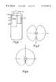
- FIG. 2is a perspective view of the antenna appearing in FIG. 1;
- FIG. 3is a diagram illustrating the horizontal polarisation radiation pattern produced when the antenna is resonant in a loop mode
- FIGS. 4A and 4Bare diagrams illustrating a ring mode resonance in the sleeve forming part of the antenna of FIG. 2;
- FIG. 5is a diagram illustrating the circular polarisation radiation pattern produced when the antenna is resonant in the ring mode
- FIG. 6is a block diagram of the telephone in FIG. 1;
- FIG. 7is a diagram showing a coupler for the telephone shown in FIGS. 1 and 6;
- FIG. 8is a perspective view of a second antenna in accordance with the invention.
- a handheld communication unitin this case, a portable telephone has a telephone body 10 with an inner face 101 , at least part of which is normally placed against the head of the user when used to make a call, so that the earphone 10 E is adjacent the user's ear.
- the telephone 10has an antenna 12 mounted at the end of the telephone body 10 with its central axis 12 A running longitudinally of the body 10 as shown.
- the antenna 12is shown in more detail in FIG. 2 .
- the antennahas two longitudinally extending elements 14 A, 14 B formed as metallic conductor tracks on the cylindrical outer surface of a ceramic core 16 .
- the core 16has an axial passage 18 with an inner metallic lining 20 , and the passage houses an axial inner feed conductor 22 .
- the inner conductor 22 and the lining 20in this case form a coaxial transmission line through the core for coupling a feed line 23 to the antenna elements 14 A, 14 B at a feed position on the distal end face 16 D of the core.
- the conductors on the corealso include corresponding connecting radial antenna elements 14 AR, 14 BR formed as metallic tracks on the distal end face 16 D, connecting diametrically opposed .ends 14 AE, 14 BE of the respective longitudinally extending elements 14 A, 14 B to the feed line.
- the junction of these radial elements and the axial transmission lineconstitutes a balanced feed termination.
- the other ends 14 AF, 14 BF of the antenna elements 14 A, 14 Bare also diametrically opposed and are linked by a cylindrical conductor 24 in the form of a plated sleeve surrounding a proximal end portion of the core 16 .
- This sleeveis, in turn, connected to the lining 22 of the axial passage 18 by a transversely extending conductive layer 26 on the proximal end face 16 P of the core 16 .
- the sleeve 24 and the conductive layer 26together form a open-ended cavity filled with the dielectric material of the core, the open end of the cavity being defined by a rim 24 R lying substantially in a plane perpendicular to the central axis 12 A of the core and the antenna as a whole.
- the sleeve 24covers a proximal portion of the antenna core 16 , thereby surrounding the coaxial transmission line formed by the lining 20 and the inner conductor 22 , the material of the core 16 filing the whole of the space between the sleeve 24 and the lining 20 .
- the sleeve 24 and the transverse layer 26together form a balun so that signals in the feed line are converted between an unbalanced state at the proximal end of the antenna to an at least approximately balanced state at the distal face 16 D.
- a further effect of the sleeve 24is that the rim 24 R of the sleeve 24 can effectively constitute an annular current path isolated from the ground represented by the outer conductor of the feed line which means that, in this isolating condition, currents circulating in the elongate helical elements 14 A, 14 B are confined to the rim 24 R so that these elements, the rim, and the radial elements 14 AR, 14 BR together form an isolated loop.
- the longitudinally extending helical elements 14 A, 14 Bare of equal length, each being in the form of simple helix executing a half turn around the axis 12 A of the core 16 with the distal and proximal ends of the helical elements respectively located in a common plane, as indicated by the chain lines 28 in FIG. 2 .
- the balanced termination of the transmission linealso, clearly, lies in this plane.
- This radiation patternis, therefore, approximally of a figure-of-8 shape in both the horizontal and vertical planes transverse to the axis 12 A, as shown by FIG. 3 .
- Orientation of the radiation pattern with respect to the antenna as shown in FIG. 2is shown by the axis system comprising axes x, y, z shown in FIGS. 1, 2 and 3 .
- the radiation patternhas two notches, one on each side of the antenna.
- the antennais mounted such that its central axis 12 A and the plane 28 are parallel to the inner face 10 I of the handset 10 , as shown in FIG. 1 .
- the relative orientations of the antenna, its radiation pattern, and the telephone body 10are evident by comparing the axis system x, y, z as it is shown in FIG. 2 with the representations of the axis system appearing in FIGS. 1 and 3.
- the antenna shown in FIG. 2also has resonances due to the sleeve acting as a waveguide.
- a ring mode resonanceis set up, characterised by at least one voltage dipole oriented diametrically across the cavity opening.
- the helical elements 14 A, 14 Bwhich, together with the radial connections 14 AR, 14 BR and the transmission line 20 , 22 , act as a feed system, impart a rotational component to the dipole such that it spins about the central axis 12 A. This effect is shown diagrammatically in the plan view of FIG.
- 4A and 4Bcorrespond to a ring resonance occurring when the circumference of the rim 24 R is substantially equal to the wavelengths ⁇ g at the required alternative operating frequency. Further ring resonances exist when the guide wavelength is an integer sub-multiple of the rim circumference so that, for instance, two or three opposed pairs of current and voltage maxima are present, spaced around the rim 24 R and the inner surface of the sleeve 24 . Thus, in the general case, one or more pairs diametrically opposed current maxima like the pair shown in FIG. 4B may exist at the operating frequency or frequencies.
- the ring resonanceyields a cardioid radiation pattern for circularly polarised radiation at the respective frequencies, as shown in FIG. 5 .
- the antennais particularly suitable for receiving circularly polarised signals when the antenna is oriented with the open end of the cavity pointing upwards. In this way, satellites in view fall within the upper dome of the cardioid response, substantially irrespective of bearing.
- the sleeve 24which is used as a balun, also to form a waveguide which is excited in a circular guide mode of resonance.
- Thisis achieved without orthogonal phasing antenna element structures such as in the prior quadrifilar antenna disclosed in GB-A-2292638, such a structure being characterised by two orthogonally related pairs of diametrically opposed helical elements arranged such that the elements of one pair form part of a conductive path which is longer than the path containing the elements of the other pair.
- each series combination of helical element 14 A, 14 B and connection element 14 AR, 14 BRhas an electrical length equal to a whole number of guide quarter-wavelengths.
- the preferred embodiment, as illustrated in FIG. 2has helical and radial element combinations each having an electrical length which is one half of the guide wavelength along those elements, so that current maximum at the balanced feed termination on the distal face 16 D is translated to current maxima at the junctions 14 AF, 14 BF of the helical elements 14 A, 14 B with the rim 24 R.
- Balance at the termination on the distal end face 16 Dis achieved by virtue of the sleeve 24 acting as a balun at the frequency of ring resonance.
- the antenna described above with reference to FIG. 2is configured and dimensioned to exhibit a ring resonance in the Globalstar uplink (user to satellite) transmit band of 1610 to 1626.5 MHz and a loop resonance in the European GSM cellular telephone band of 890 to 960 MHz.
- the first of these bandsis also the uplink band for the Iridium satellite telephone system.
- the electrical length of the sleeve rim 24 Ris at least approximately equal to the guide wavelength ⁇ g (i.e. each semicircle between the junctions of the helical elements 14 A, 14 B and the rim 24 R yields a phase shift of about 180° at a frequency within the band.
- Each helical element 14 A, 14 B and its associated radial connection element 14 AR, 14 BRhave an electrical length ⁇ g /2. Although each helical and radial element combination is considerably longer than the rim semicircle beneath, it has a similar electrical length because the effective value for the relative dielectric constant experienced by the two current paths is different such that ⁇ g along the rim is shorter than ⁇ g along the helical and radial elements at the same frequency.
- the loop resonanceoccurs when the looped conductive path represented by the radial and helical elements 14 AR, 14 A, one or other of the semicircles of the rim 24 R, and the other helical and radial elements 14 B, 14 BR, has an electrical length of one wavelength (i.e. a phase transition of 360°).
- the antenna structureis as described in the above prior published patent applications, the disclosure is which is incorporated in this specification by reference.
- the particular material used for the core 16 in the preferred embodiment in the present applicationis barium titanate or barium-neobidium titanate.
- Alternative antennas giving different combinations of resonances to suit different servicescan be designed by, for instance, first establishing suitable dimensions for the twisted loop as described in the above-mentioned GB-A-2309592 to suit one of the required operating frequencies, and then manipulating the diameter of the sleeve to produce the required whole number of guide wavelengths to suit the other of the required operating frequencies.
- the above-mentioned simulation packagecan be used to view current and field densities in a software model of the antenna or parts of the antenna.
- the ring resonancehas particular recognisable characteristics as described above with reference to FIG. 4B.
- a variety of frequency combinationsare available not only by choosing different dielectric constants and dimensions, but also by allowing the electrical lengths of the rim, the helical elements and their radial connections and the depth of the balun to be equivalent to integral multiples of the guide wavelengths or quarter guide wavelengths as appropriate.
- the depth of the balun together with the radius of the transverse conductive layer or bottom wall of the cavityare typically in the region of ⁇ g /4 to achieve balance at the distal face 16 D of the core. Odd number multiples of ⁇ g or ⁇ g /4 may be used instead.
- the ring resonancemay be combined with other resonances of the structure described in the above-mentioned prior published applications, including a quasi-monopole resonance characterised by a single-ended mode in which the radial connections 14 AR, 14 BR, the helical elements 14 A, 14 B, and the sleeve 24 combine to form linear paths from the feed termination of the distal face 16 D through to the junction of the transverse conductive layer 26 with the outer screen 20 of the transmission line.
- each helical element 14 A, 14 Bis a quarter-turn element (as opposed to a half-turn element in the embodiment of FIG. 2 ), the electrical length of each helical element and its associated radial connection 14 AR, 14 BR being generally equal to ⁇ g /4, yielding a complete 360° electrical loop at the frequency of ring resonance (each semicircle of the rim 24 R having an electrical length of ⁇ g /2).
- signalsmay pass between the antenna and the respective portions of a radio frequency (RF) front end stage of the connected radio communication equipment via a coupling stage as shown in FIG. 6 .
- the equipmentmay be a handheld telephone unit 10 having an antenna 12 as described above with reference to FIG. 2, and RF front end stage portions 30 A, 30 B forming separate RF channels constructed to receive and/or transmit signals in respective operating frequency bands.
- These front end portions 30 A, 30 Bare connected to the antenna 12 by a coupling stage 32 having a common signal line 32 A for the antenna feed line and two signal lines 32 B, 32 C for the respective front end portions 30 A, 30 B.
- the above-mentioned prior-published GB-A-2311675discloses a coupling stage in the form of a diplexer, the principle of which may be used where simultaneous use of the antenna 12 in different frequency bands is required.
- the simple combination of an impedance matching section 34 and a two-way RF switch 36(typically a p.i.n. diode device) may be used.
- the common line 32 Ais coupled to one or other of the two further signals lines or ports 32 B, 32 C, to which the different front end portions may be connected.
- the antenna 12may be used with communication equipment which is split between separate physical units rather than in a single unit 10 as shown in FIG. 6 .
Landscapes
- Engineering & Computer Science (AREA)
- Computer Networks & Wireless Communication (AREA)
- Variable-Direction Aerials And Aerial Arrays (AREA)
- Details Of Aerials (AREA)
- Support Of Aerials (AREA)
- Waveguide Aerials (AREA)
- Burglar Alarm Systems (AREA)
Abstract
Description
Claims (36)
Applications Claiming Priority (2)
| Application Number | Priority Date | Filing Date | Title |
|---|---|---|---|
| GB9828768 | 1998-12-29 | ||
| GBGB9828768.3AGB9828768D0 (en) | 1998-12-29 | 1998-12-29 | An antenna |
Publications (1)
| Publication Number | Publication Date |
|---|---|
| US6552693B1true US6552693B1 (en) | 2003-04-22 |
Family
ID=10845124
Family Applications (1)
| Application Number | Title | Priority Date | Filing Date |
|---|---|---|---|
| US09/450,850Expired - Fee RelatedUS6552693B1 (en) | 1998-12-29 | 1999-11-29 | Antenna |
Country Status (10)
| Country | Link |
|---|---|
| US (1) | US6552693B1 (en) |
| EP (1) | EP1147571B1 (en) |
| JP (1) | JP3946955B2 (en) |
| KR (1) | KR100663873B1 (en) |
| CN (1) | CN1210842C (en) |
| AT (1) | ATE320664T1 (en) |
| CA (1) | CA2357041C (en) |
| DE (1) | DE69930407T2 (en) |
| GB (2) | GB9828768D0 (en) |
| WO (1) | WO2000039887A1 (en) |
Cited By (215)
| Publication number | Priority date | Publication date | Assignee | Title |
|---|---|---|---|---|
| US20060092079A1 (en)* | 2004-10-01 | 2006-05-04 | De Rochemont L P | Ceramic antenna module and methods of manufacture thereof |
| WO2006136809A1 (en)* | 2005-06-21 | 2006-12-28 | Sarantel Limited | An antenna and an antenna feed structure |
| US20070013606A1 (en)* | 2005-07-13 | 2007-01-18 | Jabil Circuit Taiwan Limited | Coaxial cable free quadri-filar helical antenna structure |
| US20070021162A1 (en)* | 2005-07-21 | 2007-01-25 | Samsung Electronics Co., Ltd. | Antenna device for portable terminal, portable terminal, and method for providing antenna in portable terminal |
| US20070139976A1 (en)* | 2005-06-30 | 2007-06-21 | Derochemont L P | Power management module and method of manufacture |
| US20080036689A1 (en)* | 2006-05-12 | 2008-02-14 | Leisten Oliver P | Antenna system |
| US20080062064A1 (en)* | 2006-06-21 | 2008-03-13 | Christie Andrew R | Antenna and an antenna feed structure |
| US20080136738A1 (en)* | 2006-11-28 | 2008-06-12 | Oliver Paul Leisten | Dielectrically loaded antenna and an antenna assembly |
| US20080136724A1 (en)* | 2006-12-08 | 2008-06-12 | X-Ether, Inc. | Slot antenna |
| US20080174512A1 (en)* | 2006-12-20 | 2008-07-24 | Oliver Paul Leisten | Dielectrically-loaded antenna |
| US20080218430A1 (en)* | 2006-10-20 | 2008-09-11 | Oliver Paul Leisten | Dielectrically-loaded antenna |
| US20080291818A1 (en)* | 2006-12-14 | 2008-11-27 | Oliver Paul Leisten | Radio communication system |
| US20090153408A1 (en)* | 2007-12-17 | 2009-06-18 | Kazanchian Armen E | Antenna with integrated rf module |
| US20090192761A1 (en)* | 2008-01-30 | 2009-07-30 | Intuit Inc. | Performance-testing a system with functional-test software and a transformation-accelerator |
| US20100066636A1 (en)* | 2009-02-13 | 2010-03-18 | Carr William N | Multiple-Cavity Antenna |
| US20100066625A1 (en)* | 2007-12-17 | 2010-03-18 | Kazanchian Armen E | Antenna with Integrated RF Module |
| US20100207841A1 (en)* | 2009-02-13 | 2010-08-19 | Carr William N | Multiple-Resonator Antenna |
| US20100207840A1 (en)* | 2009-02-13 | 2010-08-19 | Carr William N | Multiple-Cavity Antenna |
| US20100277389A1 (en)* | 2009-05-01 | 2010-11-04 | Applied Wireless Identification Group, Inc. | Compact circular polarized antenna |
| US20110018774A1 (en)* | 2009-07-21 | 2011-01-27 | Applied Wireless Identification Group, Inc. | Compact circular polarized antenna with cavity for additional devices |
| US20110025580A1 (en)* | 2009-07-30 | 2011-02-03 | Gray Jimmie D | Antenna system and connector for antenna |
| US8134506B2 (en) | 2006-12-14 | 2012-03-13 | Sarantel Limited | Antenna arrangement |
| US8354294B2 (en) | 2006-01-24 | 2013-01-15 | De Rochemont L Pierre | Liquid chemical deposition apparatus and process and products therefrom |
| US8552708B2 (en) | 2010-06-02 | 2013-10-08 | L. Pierre de Rochemont | Monolithic DC/DC power management module with surface FET |
| US20140009353A1 (en)* | 2012-07-05 | 2014-01-09 | Dassault Aviation | Antenna unit |
| US8715839B2 (en) | 2005-06-30 | 2014-05-06 | L. Pierre de Rochemont | Electrical components and method of manufacture |
| US8749054B2 (en) | 2010-06-24 | 2014-06-10 | L. Pierre de Rochemont | Semiconductor carrier with vertical power FET module |
| US8779489B2 (en) | 2010-08-23 | 2014-07-15 | L. Pierre de Rochemont | Power FET with a resonant transistor gate |
| US8922347B1 (en) | 2009-06-17 | 2014-12-30 | L. Pierre de Rochemont | R.F. energy collection circuit for wireless devices |
| US8952858B2 (en) | 2009-06-17 | 2015-02-10 | L. Pierre de Rochemont | Frequency-selective dipole antennas |
| US9023493B2 (en) | 2010-07-13 | 2015-05-05 | L. Pierre de Rochemont | Chemically complex ablative max-phase material and method of manufacture |
| US9123768B2 (en) | 2010-11-03 | 2015-09-01 | L. Pierre de Rochemont | Semiconductor chip carriers with monolithically integrated quantum dot devices and method of manufacture thereof |
| US20160112092A1 (en)* | 2014-10-21 | 2016-04-21 | At&T Intellectual Property I, Lp | Method and apparatus for transmitting electromagnetic waves |
| US9461706B1 (en) | 2015-07-31 | 2016-10-04 | At&T Intellectual Property I, Lp | Method and apparatus for exchanging communication signals |
| US9467870B2 (en) | 2013-11-06 | 2016-10-11 | At&T Intellectual Property I, L.P. | Surface-wave communications and methods thereof |
| US9479266B2 (en) | 2013-12-10 | 2016-10-25 | At&T Intellectual Property I, L.P. | Quasi-optical coupler |
| US9490869B1 (en) | 2015-05-14 | 2016-11-08 | At&T Intellectual Property I, L.P. | Transmission medium having multiple cores and methods for use therewith |
| US9503189B2 (en) | 2014-10-10 | 2016-11-22 | At&T Intellectual Property I, L.P. | Method and apparatus for arranging communication sessions in a communication system |
| US9509415B1 (en) | 2015-06-25 | 2016-11-29 | At&T Intellectual Property I, L.P. | Methods and apparatus for inducing a fundamental wave mode on a transmission medium |
| US9520945B2 (en) | 2014-10-21 | 2016-12-13 | At&T Intellectual Property I, L.P. | Apparatus for providing communication services and methods thereof |
| US9525524B2 (en) | 2013-05-31 | 2016-12-20 | At&T Intellectual Property I, L.P. | Remote distributed antenna system |
| US9525210B2 (en) | 2014-10-21 | 2016-12-20 | At&T Intellectual Property I, L.P. | Guided-wave transmission device with non-fundamental mode propagation and methods for use therewith |
| US9531427B2 (en) | 2014-11-20 | 2016-12-27 | At&T Intellectual Property I, L.P. | Transmission device with mode division multiplexing and methods for use therewith |
| US9564947B2 (en) | 2014-10-21 | 2017-02-07 | At&T Intellectual Property I, L.P. | Guided-wave transmission device with diversity and methods for use therewith |
| US9571209B2 (en) | 2014-10-21 | 2017-02-14 | At&T Intellectual Property I, L.P. | Transmission device with impairment compensation and methods for use therewith |
| US9577306B2 (en) | 2014-10-21 | 2017-02-21 | At&T Intellectual Property I, L.P. | Guided-wave transmission device and methods for use therewith |
| US9608692B2 (en) | 2015-06-11 | 2017-03-28 | At&T Intellectual Property I, L.P. | Repeater and methods for use therewith |
| US9608740B2 (en) | 2015-07-15 | 2017-03-28 | At&T Intellectual Property I, L.P. | Method and apparatus for launching a wave mode that mitigates interference |
| US9615269B2 (en) | 2014-10-02 | 2017-04-04 | At&T Intellectual Property I, L.P. | Method and apparatus that provides fault tolerance in a communication network |
| US9628116B2 (en) | 2015-07-14 | 2017-04-18 | At&T Intellectual Property I, L.P. | Apparatus and methods for transmitting wireless signals |
| US9628854B2 (en) | 2014-09-29 | 2017-04-18 | At&T Intellectual Property I, L.P. | Method and apparatus for distributing content in a communication network |
| US9640850B2 (en) | 2015-06-25 | 2017-05-02 | At&T Intellectual Property I, L.P. | Methods and apparatus for inducing a non-fundamental wave mode on a transmission medium |
| US9654173B2 (en) | 2014-11-20 | 2017-05-16 | At&T Intellectual Property I, L.P. | Apparatus for powering a communication device and methods thereof |
| US9653770B2 (en) | 2014-10-21 | 2017-05-16 | At&T Intellectual Property I, L.P. | Guided wave coupler, coupling module and methods for use therewith |
| US9649509B2 (en) | 2011-03-31 | 2017-05-16 | Reflexion Medical, Inc. | Systems and methods for use in emission guided radiation therapy |
| US9667317B2 (en) | 2015-06-15 | 2017-05-30 | At&T Intellectual Property I, L.P. | Method and apparatus for providing security using network traffic adjustments |
| US9680670B2 (en) | 2014-11-20 | 2017-06-13 | At&T Intellectual Property I, L.P. | Transmission device with channel equalization and control and methods for use therewith |
| US9685992B2 (en) | 2014-10-03 | 2017-06-20 | At&T Intellectual Property I, L.P. | Circuit panel network and methods thereof |
| US9692101B2 (en) | 2014-08-26 | 2017-06-27 | At&T Intellectual Property I, L.P. | Guided wave couplers for coupling electromagnetic waves between a waveguide surface and a surface of a wire |
| US9699785B2 (en) | 2012-12-05 | 2017-07-04 | At&T Intellectual Property I, L.P. | Backhaul link for distributed antenna system |
| US9705561B2 (en) | 2015-04-24 | 2017-07-11 | At&T Intellectual Property I, L.P. | Directional coupling device and methods for use therewith |
| US9705571B2 (en) | 2015-09-16 | 2017-07-11 | At&T Intellectual Property I, L.P. | Method and apparatus for use with a radio distributed antenna system |
| US9722318B2 (en) | 2015-07-14 | 2017-08-01 | At&T Intellectual Property I, L.P. | Method and apparatus for coupling an antenna to a device |
| US9729197B2 (en) | 2015-10-01 | 2017-08-08 | At&T Intellectual Property I, L.P. | Method and apparatus for communicating network management traffic over a network |
| US9735833B2 (en) | 2015-07-31 | 2017-08-15 | At&T Intellectual Property I, L.P. | Method and apparatus for communications management in a neighborhood network |
| US9742462B2 (en) | 2014-12-04 | 2017-08-22 | At&T Intellectual Property I, L.P. | Transmission medium and communication interfaces and methods for use therewith |
| US9749013B2 (en) | 2015-03-17 | 2017-08-29 | At&T Intellectual Property I, L.P. | Method and apparatus for reducing attenuation of electromagnetic waves guided by a transmission medium |
| US9748626B2 (en) | 2015-05-14 | 2017-08-29 | At&T Intellectual Property I, L.P. | Plurality of cables having different cross-sectional shapes which are bundled together to form a transmission medium |
| US9749053B2 (en) | 2015-07-23 | 2017-08-29 | At&T Intellectual Property I, L.P. | Node device, repeater and methods for use therewith |
| US9755697B2 (en) | 2014-09-15 | 2017-09-05 | At&T Intellectual Property I, L.P. | Method and apparatus for sensing a condition in a transmission medium of electromagnetic waves |
| US9762289B2 (en) | 2014-10-14 | 2017-09-12 | At&T Intellectual Property I, L.P. | Method and apparatus for transmitting or receiving signals in a transportation system |
| US9769128B2 (en) | 2015-09-28 | 2017-09-19 | At&T Intellectual Property I, L.P. | Method and apparatus for encryption of communications over a network |
| US9769020B2 (en) | 2014-10-21 | 2017-09-19 | At&T Intellectual Property I, L.P. | Method and apparatus for responding to events affecting communications in a communication network |
| US9793954B2 (en) | 2015-04-28 | 2017-10-17 | At&T Intellectual Property I, L.P. | Magnetic coupling device and methods for use therewith |
| US9793951B2 (en) | 2015-07-15 | 2017-10-17 | At&T Intellectual Property I, L.P. | Method and apparatus for launching a wave mode that mitigates interference |
| US9793955B2 (en) | 2015-04-24 | 2017-10-17 | At&T Intellectual Property I, Lp | Passive electrical coupling device and methods for use therewith |
| US9800327B2 (en) | 2014-11-20 | 2017-10-24 | At&T Intellectual Property I, L.P. | Apparatus for controlling operations of a communication device and methods thereof |
| US9820146B2 (en) | 2015-06-12 | 2017-11-14 | At&T Intellectual Property I, L.P. | Method and apparatus for authentication and identity management of communicating devices |
| US9838896B1 (en) | 2016-12-09 | 2017-12-05 | At&T Intellectual Property I, L.P. | Method and apparatus for assessing network coverage |
| US9836957B2 (en) | 2015-07-14 | 2017-12-05 | At&T Intellectual Property I, L.P. | Method and apparatus for communicating with premises equipment |
| US9847850B2 (en) | 2014-10-14 | 2017-12-19 | At&T Intellectual Property I, L.P. | Method and apparatus for adjusting a mode of communication in a communication network |
| US9847566B2 (en) | 2015-07-14 | 2017-12-19 | At&T Intellectual Property I, L.P. | Method and apparatus for adjusting a field of a signal to mitigate interference |
| US9853342B2 (en) | 2015-07-14 | 2017-12-26 | At&T Intellectual Property I, L.P. | Dielectric transmission medium connector and methods for use therewith |
| US9860075B1 (en) | 2016-08-26 | 2018-01-02 | At&T Intellectual Property I, L.P. | Method and communication node for broadband distribution |
| US9866309B2 (en) | 2015-06-03 | 2018-01-09 | At&T Intellectual Property I, Lp | Host node device and methods for use therewith |
| US9865911B2 (en) | 2015-06-25 | 2018-01-09 | At&T Intellectual Property I, L.P. | Waveguide system for slot radiating first electromagnetic waves that are combined into a non-fundamental wave mode second electromagnetic wave on a transmission medium |
| US9871282B2 (en) | 2015-05-14 | 2018-01-16 | At&T Intellectual Property I, L.P. | At least one transmission medium having a dielectric surface that is covered at least in part by a second dielectric |
| US9871283B2 (en) | 2015-07-23 | 2018-01-16 | At&T Intellectual Property I, Lp | Transmission medium having a dielectric core comprised of plural members connected by a ball and socket configuration |
| US9876264B2 (en) | 2015-10-02 | 2018-01-23 | At&T Intellectual Property I, Lp | Communication system, guided wave switch and methods for use therewith |
| US9876571B2 (en) | 2015-02-20 | 2018-01-23 | At&T Intellectual Property I, Lp | Guided-wave transmission device with non-fundamental mode propagation and methods for use therewith |
| US9876605B1 (en) | 2016-10-21 | 2018-01-23 | At&T Intellectual Property I, L.P. | Launcher and coupling system to support desired guided wave mode |
| US9882257B2 (en) | 2015-07-14 | 2018-01-30 | At&T Intellectual Property I, L.P. | Method and apparatus for launching a wave mode that mitigates interference |
| US9882277B2 (en) | 2015-10-02 | 2018-01-30 | At&T Intellectual Property I, Lp | Communication device and antenna assembly with actuated gimbal mount |
| US9893795B1 (en) | 2016-12-07 | 2018-02-13 | At&T Intellectual Property I, Lp | Method and repeater for broadband distribution |
| US9906269B2 (en) | 2014-09-17 | 2018-02-27 | At&T Intellectual Property I, L.P. | Monitoring and mitigating conditions in a communication network |
| US9904535B2 (en) | 2015-09-14 | 2018-02-27 | At&T Intellectual Property I, L.P. | Method and apparatus for distributing software |
| US9912419B1 (en) | 2016-08-24 | 2018-03-06 | At&T Intellectual Property I, L.P. | Method and apparatus for managing a fault in a distributed antenna system |
| US9912027B2 (en) | 2015-07-23 | 2018-03-06 | At&T Intellectual Property I, L.P. | Method and apparatus for exchanging communication signals |
| US9913139B2 (en) | 2015-06-09 | 2018-03-06 | At&T Intellectual Property I, L.P. | Signal fingerprinting for authentication of communicating devices |
| US9912382B2 (en) | 2015-06-03 | 2018-03-06 | At&T Intellectual Property I, Lp | Network termination and methods for use therewith |
| US9911020B1 (en) | 2016-12-08 | 2018-03-06 | At&T Intellectual Property I, L.P. | Method and apparatus for tracking via a radio frequency identification device |
| US9917341B2 (en) | 2015-05-27 | 2018-03-13 | At&T Intellectual Property I, L.P. | Apparatus and method for launching electromagnetic waves and for modifying radial dimensions of the propagating electromagnetic waves |
| US9927517B1 (en) | 2016-12-06 | 2018-03-27 | At&T Intellectual Property I, L.P. | Apparatus and methods for sensing rainfall |
| US9948333B2 (en) | 2015-07-23 | 2018-04-17 | At&T Intellectual Property I, L.P. | Method and apparatus for wireless communications to mitigate interference |
| US9948354B2 (en) | 2015-04-28 | 2018-04-17 | At&T Intellectual Property I, L.P. | Magnetic coupling device with reflective plate and methods for use therewith |
| US9954287B2 (en) | 2014-11-20 | 2018-04-24 | At&T Intellectual Property I, L.P. | Apparatus for converting wireless signals and electromagnetic waves and methods thereof |
| US9967173B2 (en) | 2015-07-31 | 2018-05-08 | At&T Intellectual Property I, L.P. | Method and apparatus for authentication and identity management of communicating devices |
| US9973940B1 (en) | 2017-02-27 | 2018-05-15 | At&T Intellectual Property I, L.P. | Apparatus and methods for dynamic impedance matching of a guided wave launcher |
| US9991580B2 (en) | 2016-10-21 | 2018-06-05 | At&T Intellectual Property I, L.P. | Launcher and coupling system for guided wave mode cancellation |
| US9997819B2 (en) | 2015-06-09 | 2018-06-12 | At&T Intellectual Property I, L.P. | Transmission medium and method for facilitating propagation of electromagnetic waves via a core |
| US9998870B1 (en) | 2016-12-08 | 2018-06-12 | At&T Intellectual Property I, L.P. | Method and apparatus for proximity sensing |
| US9999038B2 (en) | 2013-05-31 | 2018-06-12 | At&T Intellectual Property I, L.P. | Remote distributed antenna system |
| US10009901B2 (en) | 2015-09-16 | 2018-06-26 | At&T Intellectual Property I, L.P. | Method, apparatus, and computer-readable storage medium for managing utilization of wireless resources between base stations |
| US10009067B2 (en) | 2014-12-04 | 2018-06-26 | At&T Intellectual Property I, L.P. | Method and apparatus for configuring a communication interface |
| US10009065B2 (en) | 2012-12-05 | 2018-06-26 | At&T Intellectual Property I, L.P. | Backhaul link for distributed antenna system |
| US10009063B2 (en) | 2015-09-16 | 2018-06-26 | At&T Intellectual Property I, L.P. | Method and apparatus for use with a radio distributed antenna system having an out-of-band reference signal |
| US10020844B2 (en) | 2016-12-06 | 2018-07-10 | T&T Intellectual Property I, L.P. | Method and apparatus for broadcast communication via guided waves |
| US10020587B2 (en) | 2015-07-31 | 2018-07-10 | At&T Intellectual Property I, L.P. | Radial antenna and methods for use therewith |
| US10027397B2 (en) | 2016-12-07 | 2018-07-17 | At&T Intellectual Property I, L.P. | Distributed antenna system and methods for use therewith |
| US10033108B2 (en) | 2015-07-14 | 2018-07-24 | At&T Intellectual Property I, L.P. | Apparatus and methods for generating an electromagnetic wave having a wave mode that mitigates interference |
| US10033107B2 (en) | 2015-07-14 | 2018-07-24 | At&T Intellectual Property I, L.P. | Method and apparatus for coupling an antenna to a device |
| US10044409B2 (en) | 2015-07-14 | 2018-08-07 | At&T Intellectual Property I, L.P. | Transmission medium and methods for use therewith |
| US10051629B2 (en) | 2015-09-16 | 2018-08-14 | At&T Intellectual Property I, L.P. | Method and apparatus for use with a radio distributed antenna system having an in-band reference signal |
| US10051483B2 (en) | 2015-10-16 | 2018-08-14 | At&T Intellectual Property I, L.P. | Method and apparatus for directing wireless signals |
| US10069535B2 (en) | 2016-12-08 | 2018-09-04 | At&T Intellectual Property I, L.P. | Apparatus and methods for launching electromagnetic waves having a certain electric field structure |
| US10074890B2 (en) | 2015-10-02 | 2018-09-11 | At&T Intellectual Property I, L.P. | Communication device and antenna with integrated light assembly |
| US10079661B2 (en) | 2015-09-16 | 2018-09-18 | At&T Intellectual Property I, L.P. | Method and apparatus for use with a radio distributed antenna system having a clock reference |
| US10090594B2 (en) | 2016-11-23 | 2018-10-02 | At&T Intellectual Property I, L.P. | Antenna system having structural configurations for assembly |
| US10090606B2 (en) | 2015-07-15 | 2018-10-02 | At&T Intellectual Property I, L.P. | Antenna system with dielectric array and methods for use therewith |
| US10103422B2 (en) | 2016-12-08 | 2018-10-16 | At&T Intellectual Property I, L.P. | Method and apparatus for mounting network devices |
| US10103801B2 (en) | 2015-06-03 | 2018-10-16 | At&T Intellectual Property I, L.P. | Host node device and methods for use therewith |
| US10136434B2 (en) | 2015-09-16 | 2018-11-20 | At&T Intellectual Property I, L.P. | Method and apparatus for use with a radio distributed antenna system having an ultra-wideband control channel |
| US10135147B2 (en) | 2016-10-18 | 2018-11-20 | At&T Intellectual Property I, L.P. | Apparatus and methods for launching guided waves via an antenna |
| US10135145B2 (en) | 2016-12-06 | 2018-11-20 | At&T Intellectual Property I, L.P. | Apparatus and methods for generating an electromagnetic wave along a transmission medium |
| US10135146B2 (en) | 2016-10-18 | 2018-11-20 | At&T Intellectual Property I, L.P. | Apparatus and methods for launching guided waves via circuits |
| US10139820B2 (en) | 2016-12-07 | 2018-11-27 | At&T Intellectual Property I, L.P. | Method and apparatus for deploying equipment of a communication system |
| US10142086B2 (en) | 2015-06-11 | 2018-11-27 | At&T Intellectual Property I, L.P. | Repeater and methods for use therewith |
| US10144036B2 (en) | 2015-01-30 | 2018-12-04 | At&T Intellectual Property I, L.P. | Method and apparatus for mitigating interference affecting a propagation of electromagnetic waves guided by a transmission medium |
| US10148016B2 (en) | 2015-07-14 | 2018-12-04 | At&T Intellectual Property I, L.P. | Apparatus and methods for communicating utilizing an antenna array |
| US10154493B2 (en) | 2015-06-03 | 2018-12-11 | At&T Intellectual Property I, L.P. | Network termination and methods for use therewith |
| US10170840B2 (en) | 2015-07-14 | 2019-01-01 | At&T Intellectual Property I, L.P. | Apparatus and methods for sending or receiving electromagnetic signals |
| US10168695B2 (en) | 2016-12-07 | 2019-01-01 | At&T Intellectual Property I, L.P. | Method and apparatus for controlling an unmanned aircraft |
| US10178445B2 (en) | 2016-11-23 | 2019-01-08 | At&T Intellectual Property I, L.P. | Methods, devices, and systems for load balancing between a plurality of waveguides |
| US10205655B2 (en) | 2015-07-14 | 2019-02-12 | At&T Intellectual Property I, L.P. | Apparatus and methods for communicating utilizing an antenna array and multiple communication paths |
| US10225025B2 (en) | 2016-11-03 | 2019-03-05 | At&T Intellectual Property I, L.P. | Method and apparatus for detecting a fault in a communication system |
| US10224634B2 (en) | 2016-11-03 | 2019-03-05 | At&T Intellectual Property I, L.P. | Methods and apparatus for adjusting an operational characteristic of an antenna |
| US10243784B2 (en) | 2014-11-20 | 2019-03-26 | At&T Intellectual Property I, L.P. | System for generating topology information and methods thereof |
| US10243270B2 (en) | 2016-12-07 | 2019-03-26 | At&T Intellectual Property I, L.P. | Beam adaptive multi-feed dielectric antenna system and methods for use therewith |
| US10264586B2 (en) | 2016-12-09 | 2019-04-16 | At&T Mobility Ii Llc | Cloud-based packet controller and methods for use therewith |
| US10291334B2 (en) | 2016-11-03 | 2019-05-14 | At&T Intellectual Property I, L.P. | System for detecting a fault in a communication system |
| US10291311B2 (en) | 2016-09-09 | 2019-05-14 | At&T Intellectual Property I, L.P. | Method and apparatus for mitigating a fault in a distributed antenna system |
| US10298293B2 (en) | 2017-03-13 | 2019-05-21 | At&T Intellectual Property I, L.P. | Apparatus of communication utilizing wireless network devices |
| US10305190B2 (en) | 2016-12-01 | 2019-05-28 | At&T Intellectual Property I, L.P. | Reflecting dielectric antenna system and methods for use therewith |
| US10312567B2 (en) | 2016-10-26 | 2019-06-04 | At&T Intellectual Property I, L.P. | Launcher with planar strip antenna and methods for use therewith |
| US10320586B2 (en) | 2015-07-14 | 2019-06-11 | At&T Intellectual Property I, L.P. | Apparatus and methods for generating non-interfering electromagnetic waves on an insulated transmission medium |
| US10326494B2 (en) | 2016-12-06 | 2019-06-18 | At&T Intellectual Property I, L.P. | Apparatus for measurement de-embedding and methods for use therewith |
| US10326689B2 (en) | 2016-12-08 | 2019-06-18 | At&T Intellectual Property I, L.P. | Method and system for providing alternative communication paths |
| US10340603B2 (en) | 2016-11-23 | 2019-07-02 | At&T Intellectual Property I, L.P. | Antenna system having shielded structural configurations for assembly |
| US10340983B2 (en) | 2016-12-09 | 2019-07-02 | At&T Intellectual Property I, L.P. | Method and apparatus for surveying remote sites via guided wave communications |
| US10341142B2 (en) | 2015-07-14 | 2019-07-02 | At&T Intellectual Property I, L.P. | Apparatus and methods for generating non-interfering electromagnetic waves on an uninsulated conductor |
| US10340601B2 (en) | 2016-11-23 | 2019-07-02 | At&T Intellectual Property I, L.P. | Multi-antenna system and methods for use therewith |
| US10340600B2 (en) | 2016-10-18 | 2019-07-02 | At&T Intellectual Property I, L.P. | Apparatus and methods for launching guided waves via plural waveguide systems |
| US10340573B2 (en) | 2016-10-26 | 2019-07-02 | At&T Intellectual Property I, L.P. | Launcher with cylindrical coupling device and methods for use therewith |
| US10348391B2 (en) | 2015-06-03 | 2019-07-09 | At&T Intellectual Property I, L.P. | Client node device with frequency conversion and methods for use therewith |
| US10355367B2 (en) | 2015-10-16 | 2019-07-16 | At&T Intellectual Property I, L.P. | Antenna structure for exchanging wireless signals |
| US10359749B2 (en) | 2016-12-07 | 2019-07-23 | At&T Intellectual Property I, L.P. | Method and apparatus for utilities management via guided wave communication |
| US10361489B2 (en) | 2016-12-01 | 2019-07-23 | At&T Intellectual Property I, L.P. | Dielectric dish antenna system and methods for use therewith |
| US10374316B2 (en) | 2016-10-21 | 2019-08-06 | At&T Intellectual Property I, L.P. | System and dielectric antenna with non-uniform dielectric |
| US10382976B2 (en) | 2016-12-06 | 2019-08-13 | At&T Intellectual Property I, L.P. | Method and apparatus for managing wireless communications based on communication paths and network device positions |
| US10389037B2 (en) | 2016-12-08 | 2019-08-20 | At&T Intellectual Property I, L.P. | Apparatus and methods for selecting sections of an antenna array and use therewith |
| US10389029B2 (en) | 2016-12-07 | 2019-08-20 | At&T Intellectual Property I, L.P. | Multi-feed dielectric antenna system with core selection and methods for use therewith |
| US10396887B2 (en) | 2015-06-03 | 2019-08-27 | At&T Intellectual Property I, L.P. | Client node device and methods for use therewith |
| US10411356B2 (en) | 2016-12-08 | 2019-09-10 | At&T Intellectual Property I, L.P. | Apparatus and methods for selectively targeting communication devices with an antenna array |
| US10439675B2 (en) | 2016-12-06 | 2019-10-08 | At&T Intellectual Property I, L.P. | Method and apparatus for repeating guided wave communication signals |
| US10446936B2 (en) | 2016-12-07 | 2019-10-15 | At&T Intellectual Property I, L.P. | Multi-feed dielectric antenna system and methods for use therewith |
| US10498044B2 (en) | 2016-11-03 | 2019-12-03 | At&T Intellectual Property I, L.P. | Apparatus for configuring a surface of an antenna |
| US10530505B2 (en) | 2016-12-08 | 2020-01-07 | At&T Intellectual Property I, L.P. | Apparatus and methods for launching electromagnetic waves along a transmission medium |
| US10535928B2 (en) | 2016-11-23 | 2020-01-14 | At&T Intellectual Property I, L.P. | Antenna system and methods for use therewith |
| US10547348B2 (en) | 2016-12-07 | 2020-01-28 | At&T Intellectual Property I, L.P. | Method and apparatus for switching transmission mediums in a communication system |
| US10601494B2 (en) | 2016-12-08 | 2020-03-24 | At&T Intellectual Property I, L.P. | Dual-band communication device and method for use therewith |
| US10637149B2 (en) | 2016-12-06 | 2020-04-28 | At&T Intellectual Property I, L.P. | Injection molded dielectric antenna and methods for use therewith |
| US10650940B2 (en) | 2015-05-15 | 2020-05-12 | At&T Intellectual Property I, L.P. | Transmission medium having a conductive material and methods for use therewith |
| US10665942B2 (en) | 2015-10-16 | 2020-05-26 | At&T Intellectual Property I, L.P. | Method and apparatus for adjusting wireless communications |
| US10679767B2 (en) | 2015-05-15 | 2020-06-09 | At&T Intellectual Property I, L.P. | Transmission medium having a conductive material and methods for use therewith |
| US10694379B2 (en) | 2016-12-06 | 2020-06-23 | At&T Intellectual Property I, L.P. | Waveguide system with device-based authentication and methods for use therewith |
| US10727599B2 (en) | 2016-12-06 | 2020-07-28 | At&T Intellectual Property I, L.P. | Launcher with slot antenna and methods for use therewith |
| US10755542B2 (en) | 2016-12-06 | 2020-08-25 | At&T Intellectual Property I, L.P. | Method and apparatus for surveillance via guided wave communication |
| US10777873B2 (en) | 2016-12-08 | 2020-09-15 | At&T Intellectual Property I, L.P. | Method and apparatus for mounting network devices |
| US10784670B2 (en) | 2015-07-23 | 2020-09-22 | At&T Intellectual Property I, L.P. | Antenna support for aligning an antenna |
| US10811767B2 (en) | 2016-10-21 | 2020-10-20 | At&T Intellectual Property I, L.P. | System and dielectric antenna with convex dielectric radome |
| US10819035B2 (en) | 2016-12-06 | 2020-10-27 | At&T Intellectual Property I, L.P. | Launcher with helical antenna and methods for use therewith |
| US10916969B2 (en) | 2016-12-08 | 2021-02-09 | At&T Intellectual Property I, L.P. | Method and apparatus for providing power using an inductive coupling |
| US10918884B2 (en) | 2016-03-09 | 2021-02-16 | Reflexion Medical, Inc. | Fluence map generation methods for radiotherapy |
| US10938108B2 (en) | 2016-12-08 | 2021-03-02 | At&T Intellectual Property I, L.P. | Frequency selective multi-feed dielectric antenna system and methods for use therewith |
| US10950928B2 (en)* | 2017-03-24 | 2021-03-16 | Mitsubishi Electric Corporation | Antenna device |
| US11032819B2 (en) | 2016-09-15 | 2021-06-08 | At&T Intellectual Property I, L.P. | Method and apparatus for use with a radio distributed antenna system having a control channel reference signal |
| US20210376482A1 (en)* | 2020-05-29 | 2021-12-02 | City University | On-chip antenna and on-chip antenna array |
| USD940149S1 (en) | 2017-06-08 | 2022-01-04 | Insulet Corporation | Display screen with a graphical user interface |
| US11406846B2 (en) | 2016-11-15 | 2022-08-09 | Reflexion Medical, Inc. | Methods for radiation delivery in emission-guided radiotherapy |
| USD977502S1 (en) | 2020-06-09 | 2023-02-07 | Insulet Corporation | Display screen with graphical user interface |
| US11857763B2 (en) | 2016-01-14 | 2024-01-02 | Insulet Corporation | Adjusting insulin delivery rates |
| US11865299B2 (en) | 2008-08-20 | 2024-01-09 | Insulet Corporation | Infusion pump systems and methods |
| US11929158B2 (en) | 2016-01-13 | 2024-03-12 | Insulet Corporation | User interface for diabetes management system |
| USD1020794S1 (en) | 2018-04-02 | 2024-04-02 | Bigfoot Biomedical, Inc. | Medication delivery device with icons |
| USD1024090S1 (en) | 2019-01-09 | 2024-04-23 | Bigfoot Biomedical, Inc. | Display screen or portion thereof with graphical user interface associated with insulin delivery |
| US11969579B2 (en) | 2017-01-13 | 2024-04-30 | Insulet Corporation | Insulin delivery methods, systems and devices |
| US12042630B2 (en) | 2017-01-13 | 2024-07-23 | Insulet Corporation | System and method for adjusting insulin delivery |
| US12064591B2 (en) | 2013-07-19 | 2024-08-20 | Insulet Corporation | Infusion pump system and method |
| US12076160B2 (en) | 2016-12-12 | 2024-09-03 | Insulet Corporation | Alarms and alerts for medication delivery devices and systems |
| US12097355B2 (en) | 2023-01-06 | 2024-09-24 | Insulet Corporation | Automatically or manually initiated meal bolus delivery with subsequent automatic safety constraint relaxation |
| US12106837B2 (en) | 2016-01-14 | 2024-10-01 | Insulet Corporation | Occlusion resolution in medication delivery devices, systems, and methods |
| US12318594B2 (en) | 2016-05-26 | 2025-06-03 | Insulet Corporation | On-body interlock for drug delivery device |
| US12318577B2 (en) | 2017-01-13 | 2025-06-03 | Insulet Corporation | System and method for adjusting insulin delivery |
| US12343502B2 (en) | 2017-01-13 | 2025-07-01 | Insulet Corporation | System and method for adjusting insulin delivery |
| US12383166B2 (en) | 2016-05-23 | 2025-08-12 | Insulet Corporation | Insulin delivery system and methods with risk-based set points |
Families Citing this family (18)
| Publication number | Priority date | Publication date | Assignee | Title |
|---|---|---|---|---|
| GB0700276D0 (en)* | 2007-01-08 | 2007-02-14 | Sarantel Ltd | A dielectrically-loaded antenna |
| GB0808661D0 (en)* | 2008-05-13 | 2008-06-18 | Sarantel Ltd | A dielectrically-loaded antenna |
| US8089421B2 (en) | 2008-01-08 | 2012-01-03 | Sarantel Limited | Dielectrically loaded antenna |
| GB0904307D0 (en) | 2009-03-12 | 2009-04-22 | Sarantel Ltd | A dielectrically-loaded antenna |
| BRPI1009330A2 (en)* | 2009-03-12 | 2016-03-08 | Sarantel Ltd | dielectrically charged antenna |
| GB0911635D0 (en)* | 2009-07-03 | 2009-08-12 | Sarantel Ltd | A dielectrically-loaded antenna |
| US8456375B2 (en) | 2009-05-05 | 2013-06-04 | Sarantel Limited | Multifilar antenna |
| GB2477289B (en)* | 2010-01-27 | 2014-08-13 | Harris Corp | A radio communication apparatus having improved resistance to common mode noise |
| GB2491282B (en)* | 2010-01-27 | 2014-12-03 | Harris Corp | A dielectrically loaded antenna and a method of manufacture thereof |
| US8599101B2 (en) | 2010-01-27 | 2013-12-03 | Sarantel Limited | Dielectrically loaded antenna and radio communication apparatus |
| GB201012923D0 (en)* | 2010-07-30 | 2010-09-15 | Sarantel Ltd | An antenna |
| GB201108016D0 (en) | 2011-05-13 | 2011-06-29 | Sarantel Ltd | An antenna and a method of manufacture thereof |
| GB201109000D0 (en) | 2011-05-24 | 2011-07-13 | Sarantel Ltd | A dielectricaly loaded antenna |
| CN107968249B (en)* | 2016-10-20 | 2019-08-30 | 香港城市大学深圳研究院 | A circularly polarized reconfigurable quadrifilar helical antenna |
| US10014573B2 (en) | 2016-11-03 | 2018-07-03 | Nidec Motor Corporation | Directional antenna for wireless motor connection |
| CN107785653B (en)* | 2017-11-29 | 2024-02-06 | 中国电子科技集团公司第五十四研究所 | A spiral vibrator antenna |
| CN110308336B (en)* | 2019-07-04 | 2021-05-07 | 中国人民解放军63660部队 | Dielectric loaded D-dot electric field measuring sensor |
| DE102020210511A1 (en)* | 2020-08-19 | 2022-02-24 | Hagenuk Marinekommunikation Gmbh | Antenna with a first and a second feed point |
Citations (89)
| Publication number | Priority date | Publication date | Assignee | Title |
|---|---|---|---|---|
| US2575377A (en) | 1945-11-13 | 1951-11-20 | Robert J Wohl | Short wave antenna |
| US2763003A (en) | 1953-07-01 | 1956-09-11 | Edward F Harris | Helical antenna construction |
| GB762415A (en) | 1954-06-17 | 1956-11-28 | Emi Ltd | Improvements in or relating to aerials |
| GB840850A (en) | 1955-07-19 | 1960-07-13 | Telefunken Gmbh | Improvements relating to high frequency aerial-arrangements |
| GB1198410A (en) | 1967-12-15 | 1970-07-15 | Onera (Off Nat Aerospatiale) | Antennae |
| US3611198A (en) | 1970-05-04 | 1971-10-05 | Zenith Radio Corp | Frequency-selective coupling circuit for all-channel television antenna having uhf/vhf crossover network within uhf tuner |
| US3633210A (en) | 1967-05-26 | 1972-01-04 | Philco Ford Corp | Unbalanced conical spiral antenna |
| US3906509A (en) | 1974-03-11 | 1975-09-16 | Raymond H Duhamel | Circularly polarized helix and spiral antennas |
| US3940772A (en) | 1974-11-08 | 1976-02-24 | Rca Corporation | Circularly polarized, broadside firing tetrahelical antenna |
| US4008479A (en) | 1975-11-03 | 1977-02-15 | Chu Associates, Inc. | Dual-frequency circularly polarized spiral antenna for satellite navigation |
| US4008478A (en) | 1975-12-31 | 1977-02-15 | The United States Of America As Represented By The Secretary Of The Army | Rifle barrel serving as radio antenna |
| US4114164A (en) | 1976-12-17 | 1978-09-12 | Transco Products, Inc. | Broadband spiral antenna |
| US4148030A (en) | 1977-06-13 | 1979-04-03 | Rca Corporation | Helical antennas |
| US4160979A (en) | 1976-06-21 | 1979-07-10 | National Research Development Corporation | Helical radio antennae |
| US4168479A (en) | 1977-10-25 | 1979-09-18 | The United States Of America As Represented By The Secretary Of The Navy | Millimeter wave MIC diplexer |
| US4204212A (en) | 1978-12-06 | 1980-05-20 | The United States Of America As Represented By The Secretary Of The Army | Conformal spiral antenna |
| US4323900A (en) | 1979-10-01 | 1982-04-06 | The United States Of America As Represented By The Secretary Of The Navy | Omnidirectional microstrip antenna |
| EP0051018A1 (en) | 1980-10-17 | 1982-05-05 | Schlumberger Limited | Method and apparatus for electromagnetic borehole logging |
| US4329689A (en) | 1978-10-10 | 1982-05-11 | The Boeing Company | Microstrip antenna structure having stacked microstrip elements |
| US4349824A (en) | 1980-10-01 | 1982-09-14 | The United States Of America As Represented By The Secretary Of The Navy | Around-a-mast quadrifilar microstrip antenna |
| DE3217437A1 (en) | 1982-03-25 | 1983-11-10 | Licentia Patent-Verwaltungs-Gmbh, 6000 Frankfurt | MICROWAVE DIRECTIONAL ANTENNA FROM A DIELECTRIC LINE |
| US4442438A (en) | 1982-03-29 | 1984-04-10 | Motorola, Inc. | Helical antenna structure capable of resonating at two different frequencies |
| FR2570546A1 (en) | 1984-09-17 | 1986-03-21 | Europ Agence Spatiale | Helicoid multiwire antenna for simultaneous transmission of a plurality of VHF/UHF transmission and reception signals |
| US4608572A (en) | 1982-12-10 | 1986-08-26 | The Boeing Company | Broad-band antenna structure having frequency-independent, low-loss ground plane |
| US4608574A (en) | 1984-05-16 | 1986-08-26 | The United States Of America As Represented By The Secretary Of The Air Force | Backfire bifilar helix antenna |
| EP0198578A1 (en) | 1985-02-19 | 1986-10-22 | Raymond Horace Du Hamel | Dual polarised sinuous antennas |
| US4697192A (en) | 1985-04-16 | 1987-09-29 | Texas Instruments Incorporated | Two arm planar/conical/helix antenna |
| EP0241921A1 (en) | 1986-04-15 | 1987-10-21 | Alcatel Espace | High-efficiency antenna |
| US4706049A (en) | 1985-10-03 | 1987-11-10 | Motorola, Inc. | Dual adjacent directional filters/combiners |
| FR2603743A1 (en) | 1986-09-10 | 1988-03-11 | Aisin Seiki | AXIAL MODE HELICOID ANTENNA |
| GB2196483A (en) | 1986-10-16 | 1988-04-27 | C S Antennas Ltd | Antenna |
| GB2202380A (en) | 1987-03-20 | 1988-09-21 | Philips Electronic Associated | Helical antenna |
| SU1483511A1 (en) | 1986-12-30 | 1989-05-30 | Организация П/Я В-8942 | Helical aerial |
| EP0320404A1 (en) | 1987-12-10 | 1989-06-14 | Centre National D'etudes Spatiales | Helix-type antenna and its manufacturing process |
| US4862184A (en) | 1987-02-06 | 1989-08-29 | George Ploussios | Method and construction of helical antenna |
| EP0332139A2 (en) | 1988-03-10 | 1989-09-13 | Kabushiki Kaisha Toyota Chuo Kenkyusho | Wide band antenna for mobile communications |
| US4902992A (en) | 1988-03-29 | 1990-02-20 | The United States Of America As Represented By The Secretary Of The Navy | Millimeter-wave multiplexers |
| US4910481A (en) | 1988-03-07 | 1990-03-20 | Kokusai Denki Kabushiki Kaisha | Branching filter |
| US4940992A (en) | 1988-04-11 | 1990-07-10 | Nguyen Tuan K | Balanced low profile hybrid antenna |
| US4980694A (en) | 1989-04-14 | 1990-12-25 | Goldstar Products Company, Limited | Portable communication apparatus with folded-slot edge-congruent antenna |
| US5019829A (en) | 1989-02-08 | 1991-05-28 | Heckman Douglas E | Plug-in package for microwave integrated circuit having cover-mounted antenna |
| EP0429255A2 (en) | 1989-11-17 | 1991-05-29 | Harada Industry Co., Ltd. | Three-wave shared antenna (radio, AM and FM) for automobile |
| US5023866A (en) | 1987-02-27 | 1991-06-11 | Motorola, Inc. | Duplexer filter having harmonic rejection to control flyback |
| WO1991011038A1 (en) | 1990-01-08 | 1991-07-25 | Toyo Communication Equipment Co., Ltd. | Four-wire fractional winding helical antenna and manufacturing method thereof |
| US5055852A (en) | 1989-06-20 | 1991-10-08 | Alcatel Espace | Diplexing radiating element |
| GB2243724A (en) | 1990-02-27 | 1991-11-06 | Kokusai Denshin Denwa Co Ltd | Quadrifilar helix antenna |
| JPH03274904A (en) | 1990-03-26 | 1991-12-05 | Nippon Telegr & Teleph Corp <Ntt> | Helical antenna |
| US5081469A (en) | 1987-07-16 | 1992-01-14 | Sensormatic Electronics Corporation | Enhanced bandwidth helical antenna |
| EP0469741A1 (en) | 1990-08-02 | 1992-02-05 | Symmetricom, Inc. | Radio frequency apparatus |
| US5099249A (en) | 1987-10-13 | 1992-03-24 | Seavey Engineering Associates, Inc. | Microstrip antenna for vehicular satellite communications |
| GB2248344A (en) | 1990-09-25 | 1992-04-01 | Secr Defence | Three-dimensional patch antenna array |
| WO1992005602A1 (en) | 1990-09-26 | 1992-04-02 | Garmin International, Inc. | Personal positioning satellite navigator with printed quadrifilar helical antenna |
| WO1992017915A1 (en) | 1991-03-29 | 1992-10-15 | Centre Regional D'innovation Et De Transfert De Technologie En Electronique Et Communications (Critt) Loi 1901 | Omnidirectionnal printed cylindrical antenna and marine radar transponder using such antennas |
| US5170493A (en) | 1988-07-25 | 1992-12-08 | Iimorrow, Inc. | Combined low frequency receive and high frequency transceive antenna system and method |
| EP0521511A2 (en) | 1991-07-05 | 1993-01-07 | Sharp Kabushiki Kaisha | Back fire helical antenna |
| US5255005A (en) | 1989-11-10 | 1993-10-19 | L'etat Francais Represente Par Leministre Des Pastes Telecommunications Et De L'espace | Dual layer resonant quadrifilar helix antenna |
| US5258728A (en) | 1987-09-30 | 1993-11-02 | Fujitsu Ten Limited | Antenna circuit for a multi-band antenna |
| US5281934A (en) | 1992-04-09 | 1994-01-25 | Trw Inc. | Common input junction, multioctave printed microwave multiplexer |
| EP0588271A1 (en) | 1992-09-18 | 1994-03-23 | ALCATEL ITALIA S.p.A. | Portable transceiver apparatus with low irradiation of the user, employing an antenna having an asymmetric radiation pattern |
| EP0588465A1 (en) | 1992-09-11 | 1994-03-23 | Ngk Insulators, Ltd. | Ceramic dielectric for antennas |
| US5298910A (en) | 1991-03-18 | 1994-03-29 | Hitachi, Ltd. | Antenna for radio apparatus |
| EP0590534A1 (en) | 1992-09-28 | 1994-04-06 | Ntt Mobile Communications Network Inc. | Portable radio unit |
| US5329287A (en) | 1992-02-24 | 1994-07-12 | Cal Corporation | End loaded helix antenna |
| US5341149A (en) | 1991-03-25 | 1994-08-23 | Nokia Mobile Phones Ltd. | Antenna rod and procedure for manufacturing same |
| US5345248A (en) | 1992-07-22 | 1994-09-06 | Space Systems/Loral, Inc. | Staggered helical array antenna |
| US5349365A (en) | 1991-10-21 | 1994-09-20 | Ow Steven G | Quadrifilar helix antenna |
| US5349361A (en) | 1989-10-05 | 1994-09-20 | Harada Kogyo Kabushiki Kaisha | Three-wave antenna for vehicles |
| US5406296A (en) | 1992-05-11 | 1995-04-11 | Harada Kogyo Kabushiki Kaisha | Three-wave antenna for vehicles |
| US5406693A (en) | 1992-07-06 | 1995-04-18 | Harada Kogyo Kabushiki Kaisha | Method of manufacturing a helical antenna for satellite communication |
| EP0652645A1 (en) | 1993-10-09 | 1995-05-10 | Philips Patentverwaltung GmbH | Portable radio device with means for protecting its user from electromagnetic radiation |
| US5450093A (en) | 1994-04-20 | 1995-09-12 | The United States Of America As Represented By The Secretary Of The Navy | Center-fed multifilar helix antenna |
| JPH07249973A (en) | 1994-03-14 | 1995-09-26 | Toshiba Corp | Electronics |
| US5479180A (en) | 1994-03-23 | 1995-12-26 | The United States Of America As Represented By The Secretary Of The Army | High power ultra broadband antenna |
| JPH088408A (en) | 1994-01-18 | 1996-01-12 | Rohm Co Ltd | Nonvolatile memory |
| GB2292257A (en) | 1994-06-22 | 1996-02-14 | Sidney John Branson | Radio frequency antenna |
| GB2292638A (en) | 1994-08-25 | 1996-02-28 | Symmetricom Inc | Three-dimensional antenna structure |
| US5541613A (en) | 1994-11-03 | 1996-07-30 | Hughes Aircraft Company, Hughes Electronics | Efficient broadband antenna system using photonic bandgap crystals |
| US5548255A (en) | 1995-06-23 | 1996-08-20 | Microphase Corporation | Compact diplexer connection circuit |
| US5612707A (en) | 1992-04-24 | 1997-03-18 | Industrial Research Limited | Steerable beam helix antenna |
| EP0777293A1 (en) | 1995-12-06 | 1997-06-04 | Murata Manufacturing Co., Ltd. | Chip antenna having multiple resonance frequencies |
| GB2309592A (en) | 1996-01-23 | 1997-07-30 | Symmetricom Inc | Miniature antenna |
| US5661494A (en)* | 1995-03-24 | 1997-08-26 | The United States Of America As Represented By The Administrator Of The National Aeronautics And Space Administration | High performance circularly polarized microstrip antenna |
| GB2310543A (en) | 1996-02-23 | 1997-08-27 | Symmetricom Inc | An antenna |
| GB2311675A (en) | 1996-03-29 | 1997-10-01 | Symmetricom Inc | Dual frequency helical aerial with diplexer to separate the bands |
| GB2317057A (en) | 1996-11-01 | 1998-03-11 | Symmetricom Inc | Dielectric-loaded antenna |
| US5748154A (en) | 1992-09-30 | 1998-05-05 | Fujitsu Limited | Miniature antenna for portable radio communication equipment |
| GB2321785A (en) | 1996-11-27 | 1998-08-05 | Symmetricom Inc | A dielectric-loaded antenna |
| GB2326532A (en) | 1994-08-25 | 1998-12-23 | Symmetricom Inc | Antenna |
| JP3274904B2 (en) | 1993-03-31 | 2002-04-15 | 株式会社東芝 | Reactor power measurement device |
Family Cites Families (2)
| Publication number | Priority date | Publication date | Assignee | Title |
|---|---|---|---|---|
| AU720873B2 (en)* | 1996-01-23 | 2000-06-15 | Sarantel Limited | An antenna |
| GB9813002D0 (en)* | 1998-06-16 | 1998-08-12 | Symmetricom Inc | An antenna |
- 1998
- 1998-12-29GBGBGB9828768.3Apatent/GB9828768D0/ennot_activeCeased
- 1999
- 1999-11-19JPJP2000591694Apatent/JP3946955B2/ennot_activeExpired - Fee Related
- 1999-11-19WOPCT/GB1999/003885patent/WO2000039887A1/enactiveIP Right Grant
- 1999-11-19CNCNB998163872Apatent/CN1210842C/ennot_activeExpired - Fee Related
- 1999-11-19KRKR1020017008736Apatent/KR100663873B1/ennot_activeExpired - Fee Related
- 1999-11-19DEDE69930407Tpatent/DE69930407T2/ennot_activeExpired - Lifetime
- 1999-11-19ATAT99956177Tpatent/ATE320664T1/ennot_activeIP Right Cessation
- 1999-11-19CACA002357041Apatent/CA2357041C/ennot_activeExpired - Fee Related
- 1999-11-19GBGB9927490Apatent/GB2346014B/ennot_activeExpired - Fee Related
- 1999-11-19EPEP99956177Apatent/EP1147571B1/ennot_activeExpired - Lifetime
- 1999-11-29USUS09/450,850patent/US6552693B1/ennot_activeExpired - Fee Related
Patent Citations (101)
| Publication number | Priority date | Publication date | Assignee | Title |
|---|---|---|---|---|
| US2575377A (en) | 1945-11-13 | 1951-11-20 | Robert J Wohl | Short wave antenna |
| US2763003A (en) | 1953-07-01 | 1956-09-11 | Edward F Harris | Helical antenna construction |
| GB762415A (en) | 1954-06-17 | 1956-11-28 | Emi Ltd | Improvements in or relating to aerials |
| GB840850A (en) | 1955-07-19 | 1960-07-13 | Telefunken Gmbh | Improvements relating to high frequency aerial-arrangements |
| US3633210A (en) | 1967-05-26 | 1972-01-04 | Philco Ford Corp | Unbalanced conical spiral antenna |
| GB1198410A (en) | 1967-12-15 | 1970-07-15 | Onera (Off Nat Aerospatiale) | Antennae |
| US3611198A (en) | 1970-05-04 | 1971-10-05 | Zenith Radio Corp | Frequency-selective coupling circuit for all-channel television antenna having uhf/vhf crossover network within uhf tuner |
| US3906509A (en) | 1974-03-11 | 1975-09-16 | Raymond H Duhamel | Circularly polarized helix and spiral antennas |
| US3940772A (en) | 1974-11-08 | 1976-02-24 | Rca Corporation | Circularly polarized, broadside firing tetrahelical antenna |
| US4008479A (en) | 1975-11-03 | 1977-02-15 | Chu Associates, Inc. | Dual-frequency circularly polarized spiral antenna for satellite navigation |
| US4008478A (en) | 1975-12-31 | 1977-02-15 | The United States Of America As Represented By The Secretary Of The Army | Rifle barrel serving as radio antenna |
| US4160979A (en) | 1976-06-21 | 1979-07-10 | National Research Development Corporation | Helical radio antennae |
| US4270128A (en) | 1976-06-21 | 1981-05-26 | National Research Development Corporation | Radio antennae |
| GB1568436A (en) | 1976-12-17 | 1980-05-29 | Transco Prod Inc | Broadband spiral antenna |
| US4114164A (en) | 1976-12-17 | 1978-09-12 | Transco Products, Inc. | Broadband spiral antenna |
| US4148030A (en) | 1977-06-13 | 1979-04-03 | Rca Corporation | Helical antennas |
| US4168479A (en) | 1977-10-25 | 1979-09-18 | The United States Of America As Represented By The Secretary Of The Navy | Millimeter wave MIC diplexer |
| US4329689A (en) | 1978-10-10 | 1982-05-11 | The Boeing Company | Microstrip antenna structure having stacked microstrip elements |
| US4204212A (en) | 1978-12-06 | 1980-05-20 | The United States Of America As Represented By The Secretary Of The Army | Conformal spiral antenna |
| US4323900A (en) | 1979-10-01 | 1982-04-06 | The United States Of America As Represented By The Secretary Of The Navy | Omnidirectional microstrip antenna |
| US4349824A (en) | 1980-10-01 | 1982-09-14 | The United States Of America As Represented By The Secretary Of The Navy | Around-a-mast quadrifilar microstrip antenna |
| EP0051018A1 (en) | 1980-10-17 | 1982-05-05 | Schlumberger Limited | Method and apparatus for electromagnetic borehole logging |
| DE3217437A1 (en) | 1982-03-25 | 1983-11-10 | Licentia Patent-Verwaltungs-Gmbh, 6000 Frankfurt | MICROWAVE DIRECTIONAL ANTENNA FROM A DIELECTRIC LINE |
| US4442438A (en) | 1982-03-29 | 1984-04-10 | Motorola, Inc. | Helical antenna structure capable of resonating at two different frequencies |
| US4608572A (en) | 1982-12-10 | 1986-08-26 | The Boeing Company | Broad-band antenna structure having frequency-independent, low-loss ground plane |
| US4608574A (en) | 1984-05-16 | 1986-08-26 | The United States Of America As Represented By The Secretary Of The Air Force | Backfire bifilar helix antenna |
| FR2570546A1 (en) | 1984-09-17 | 1986-03-21 | Europ Agence Spatiale | Helicoid multiwire antenna for simultaneous transmission of a plurality of VHF/UHF transmission and reception signals |
| EP0198578A1 (en) | 1985-02-19 | 1986-10-22 | Raymond Horace Du Hamel | Dual polarised sinuous antennas |
| US4697192A (en) | 1985-04-16 | 1987-09-29 | Texas Instruments Incorporated | Two arm planar/conical/helix antenna |
| US4706049A (en) | 1985-10-03 | 1987-11-10 | Motorola, Inc. | Dual adjacent directional filters/combiners |
| EP0241921A1 (en) | 1986-04-15 | 1987-10-21 | Alcatel Espace | High-efficiency antenna |
| FR2603743A1 (en) | 1986-09-10 | 1988-03-11 | Aisin Seiki | AXIAL MODE HELICOID ANTENNA |
| GB2196483A (en) | 1986-10-16 | 1988-04-27 | C S Antennas Ltd | Antenna |
| SU1483511A1 (en) | 1986-12-30 | 1989-05-30 | Организация П/Я В-8942 | Helical aerial |
| US4862184A (en) | 1987-02-06 | 1989-08-29 | George Ploussios | Method and construction of helical antenna |
| US5023866A (en) | 1987-02-27 | 1991-06-11 | Motorola, Inc. | Duplexer filter having harmonic rejection to control flyback |
| GB2202380A (en) | 1987-03-20 | 1988-09-21 | Philips Electronic Associated | Helical antenna |
| US5081469A (en) | 1987-07-16 | 1992-01-14 | Sensormatic Electronics Corporation | Enhanced bandwidth helical antenna |
| US5258728A (en) | 1987-09-30 | 1993-11-02 | Fujitsu Ten Limited | Antenna circuit for a multi-band antenna |
| US5099249A (en) | 1987-10-13 | 1992-03-24 | Seavey Engineering Associates, Inc. | Microstrip antenna for vehicular satellite communications |
| EP0320404A1 (en) | 1987-12-10 | 1989-06-14 | Centre National D'etudes Spatiales | Helix-type antenna and its manufacturing process |
| US5134422A (en) | 1987-12-10 | 1992-07-28 | Centre National D'etudes Spatiales | Helical type antenna and manufacturing method thereof |
| US4910481A (en) | 1988-03-07 | 1990-03-20 | Kokusai Denki Kabushiki Kaisha | Branching filter |
| EP0332139A2 (en) | 1988-03-10 | 1989-09-13 | Kabushiki Kaisha Toyota Chuo Kenkyusho | Wide band antenna for mobile communications |
| US4902992A (en) | 1988-03-29 | 1990-02-20 | The United States Of America As Represented By The Secretary Of The Navy | Millimeter-wave multiplexers |
| US4940992A (en) | 1988-04-11 | 1990-07-10 | Nguyen Tuan K | Balanced low profile hybrid antenna |
| US5170493A (en) | 1988-07-25 | 1992-12-08 | Iimorrow, Inc. | Combined low frequency receive and high frequency transceive antenna system and method |
| US5019829A (en) | 1989-02-08 | 1991-05-28 | Heckman Douglas E | Plug-in package for microwave integrated circuit having cover-mounted antenna |
| US4980694A (en) | 1989-04-14 | 1990-12-25 | Goldstar Products Company, Limited | Portable communication apparatus with folded-slot edge-congruent antenna |
| US5055852A (en) | 1989-06-20 | 1991-10-08 | Alcatel Espace | Diplexing radiating element |
| US5349361A (en) | 1989-10-05 | 1994-09-20 | Harada Kogyo Kabushiki Kaisha | Three-wave antenna for vehicles |
| US5255005A (en) | 1989-11-10 | 1993-10-19 | L'etat Francais Represente Par Leministre Des Pastes Telecommunications Et De L'espace | Dual layer resonant quadrifilar helix antenna |
| EP0429255A2 (en) | 1989-11-17 | 1991-05-29 | Harada Industry Co., Ltd. | Three-wave shared antenna (radio, AM and FM) for automobile |
| EP0465658A1 (en) | 1990-01-08 | 1992-01-15 | Toyo Communication Equipment Co. Ltd. | Four-wire fractional winding helical antenna and manufacturing method thereof |
| WO1991011038A1 (en) | 1990-01-08 | 1991-07-25 | Toyo Communication Equipment Co., Ltd. | Four-wire fractional winding helical antenna and manufacturing method thereof |
| US5170176A (en) | 1990-02-27 | 1992-12-08 | Kokusai Denshin Denwa Co., Ltd. | Quadrifilar helix antenna |
| GB2243724A (en) | 1990-02-27 | 1991-11-06 | Kokusai Denshin Denwa Co Ltd | Quadrifilar helix antenna |
| JPH03274904A (en) | 1990-03-26 | 1991-12-05 | Nippon Telegr & Teleph Corp <Ntt> | Helical antenna |
| GB2246910A (en) | 1990-08-02 | 1992-02-12 | Polytechnic Electronics Plc | Antenna |
| EP0469741A1 (en) | 1990-08-02 | 1992-02-05 | Symmetricom, Inc. | Radio frequency apparatus |
| GB2248344A (en) | 1990-09-25 | 1992-04-01 | Secr Defence | Three-dimensional patch antenna array |
| WO1992005602A1 (en) | 1990-09-26 | 1992-04-02 | Garmin International, Inc. | Personal positioning satellite navigator with printed quadrifilar helical antenna |
| US5298910A (en) | 1991-03-18 | 1994-03-29 | Hitachi, Ltd. | Antenna for radio apparatus |
| US5341149A (en) | 1991-03-25 | 1994-08-23 | Nokia Mobile Phones Ltd. | Antenna rod and procedure for manufacturing same |
| WO1992017915A1 (en) | 1991-03-29 | 1992-10-15 | Centre Regional D'innovation Et De Transfert De Technologie En Electronique Et Communications (Critt) Loi 1901 | Omnidirectionnal printed cylindrical antenna and marine radar transponder using such antennas |
| EP0521511A2 (en) | 1991-07-05 | 1993-01-07 | Sharp Kabushiki Kaisha | Back fire helical antenna |
| US5346300A (en) | 1991-07-05 | 1994-09-13 | Sharp Kabushiki Kaisha | Back fire helical antenna |
| US5349365A (en) | 1991-10-21 | 1994-09-20 | Ow Steven G | Quadrifilar helix antenna |
| US5329287A (en) | 1992-02-24 | 1994-07-12 | Cal Corporation | End loaded helix antenna |
| US5281934A (en) | 1992-04-09 | 1994-01-25 | Trw Inc. | Common input junction, multioctave printed microwave multiplexer |
| US5612707A (en) | 1992-04-24 | 1997-03-18 | Industrial Research Limited | Steerable beam helix antenna |
| US5406296A (en) | 1992-05-11 | 1995-04-11 | Harada Kogyo Kabushiki Kaisha | Three-wave antenna for vehicles |
| US5406693A (en) | 1992-07-06 | 1995-04-18 | Harada Kogyo Kabushiki Kaisha | Method of manufacturing a helical antenna for satellite communication |
| US5345248A (en) | 1992-07-22 | 1994-09-06 | Space Systems/Loral, Inc. | Staggered helical array antenna |
| EP0588465A1 (en) | 1992-09-11 | 1994-03-23 | Ngk Insulators, Ltd. | Ceramic dielectric for antennas |
| EP0588271A1 (en) | 1992-09-18 | 1994-03-23 | ALCATEL ITALIA S.p.A. | Portable transceiver apparatus with low irradiation of the user, employing an antenna having an asymmetric radiation pattern |
| EP0590534A1 (en) | 1992-09-28 | 1994-04-06 | Ntt Mobile Communications Network Inc. | Portable radio unit |
| US5748154A (en) | 1992-09-30 | 1998-05-05 | Fujitsu Limited | Miniature antenna for portable radio communication equipment |
| JP3274904B2 (en) | 1993-03-31 | 2002-04-15 | 株式会社東芝 | Reactor power measurement device |
| EP0652645A1 (en) | 1993-10-09 | 1995-05-10 | Philips Patentverwaltung GmbH | Portable radio device with means for protecting its user from electromagnetic radiation |
| JPH088408A (en) | 1994-01-18 | 1996-01-12 | Rohm Co Ltd | Nonvolatile memory |
| JPH07249973A (en) | 1994-03-14 | 1995-09-26 | Toshiba Corp | Electronics |
| US5479180A (en) | 1994-03-23 | 1995-12-26 | The United States Of America As Represented By The Secretary Of The Army | High power ultra broadband antenna |
| US5450093A (en) | 1994-04-20 | 1995-09-12 | The United States Of America As Represented By The Secretary Of The Navy | Center-fed multifilar helix antenna |
| GB2292257A (en) | 1994-06-22 | 1996-02-14 | Sidney John Branson | Radio frequency antenna |
| GB2326532A (en) | 1994-08-25 | 1998-12-23 | Symmetricom Inc | Antenna |
| GB2292638A (en) | 1994-08-25 | 1996-02-28 | Symmetricom Inc | Three-dimensional antenna structure |
| US5854608A (en) | 1994-08-25 | 1998-12-29 | Symetri Com, Inc. | Helical antenna having a solid dielectric core |
| US5541613A (en) | 1994-11-03 | 1996-07-30 | Hughes Aircraft Company, Hughes Electronics | Efficient broadband antenna system using photonic bandgap crystals |
| US5661494A (en)* | 1995-03-24 | 1997-08-26 | The United States Of America As Represented By The Administrator Of The National Aeronautics And Space Administration | High performance circularly polarized microstrip antenna |
| US5548255A (en) | 1995-06-23 | 1996-08-20 | Microphase Corporation | Compact diplexer connection circuit |
| EP0777293A1 (en) | 1995-12-06 | 1997-06-04 | Murata Manufacturing Co., Ltd. | Chip antenna having multiple resonance frequencies |
| GB2309592A (en) | 1996-01-23 | 1997-07-30 | Symmetricom Inc | Miniature antenna |
| US5945963A (en) | 1996-01-23 | 1999-08-31 | Symmetricom, Inc. | Dielectrically loaded antenna and a handheld radio communication unit including such an antenna |
| GB2310543A (en) | 1996-02-23 | 1997-08-27 | Symmetricom Inc | An antenna |
| US5859621A (en) | 1996-02-23 | 1999-01-12 | Symmetricom, Inc. | Antenna |
| EP0791978A2 (en) | 1996-02-23 | 1997-08-27 | Symmetricom, Inc. | An antenna |
| GB2311675A (en) | 1996-03-29 | 1997-10-01 | Symmetricom Inc | Dual frequency helical aerial with diplexer to separate the bands |
| US5963180A (en) | 1996-03-29 | 1999-10-05 | Symmetricom, Inc. | Antenna system for radio signals in at least two spaced-apart frequency bands |
| GB2317057A (en) | 1996-11-01 | 1998-03-11 | Symmetricom Inc | Dielectric-loaded antenna |
| GB2321785A (en) | 1996-11-27 | 1998-08-05 | Symmetricom Inc | A dielectric-loaded antenna |
Non-Patent Citations (5)
| Title |
|---|
| Casey, J. et al., "Square Helical Antenna with a Dielectric Core", IEEE Transactions on Electromagnetic Compatibility, vol. 30, No. 4, Nov. 1988, pp. 429-436. |
| Espaignol, J. et al., "Duplexeur A Resonateurs Dielectriques En Bande K", 6es Journees Nationales Microondes, Montpellier, Jun. 21-23, 1989, Centre D'Electronique De Montpellier, pp. 321-322. |
| Krall et al., IEEE Transactions on Antennas and Propagation, vol. AP-27, No. 6, Nov. 1979, pp. 850-853. |
| Nakano, H., "Helical and Spiral Antennas-A Numerical Approach", Research Studies Press Ltd., England, pp. 1-261 (1987). |
| Nakano, H., "Helical and Spiral Antennas—A Numerical Approach", Research Studies Press Ltd., England, pp. 1-261 (1987). |
Cited By (328)
| Publication number | Priority date | Publication date | Assignee | Title |
|---|---|---|---|---|
| US9735148B2 (en) | 2002-02-19 | 2017-08-15 | L. Pierre de Rochemont | Semiconductor carrier with vertical power FET module |
| US20060092079A1 (en)* | 2004-10-01 | 2006-05-04 | De Rochemont L P | Ceramic antenna module and methods of manufacture thereof |
| US8593819B2 (en) | 2004-10-01 | 2013-11-26 | L. Pierre de Rochemont | Ceramic antenna module and methods of manufacture thereof |
| US10673130B2 (en) | 2004-10-01 | 2020-06-02 | L. Pierre de Rochemont | Ceramic antenna module and methods of manufacture thereof |
| US9520649B2 (en) | 2004-10-01 | 2016-12-13 | L. Pierre de Rochemont | Ceramic antenna module and methods of manufacture thereof |
| US20090011922A1 (en)* | 2004-10-01 | 2009-01-08 | De Rochemont L Pierre | Ceramic antenna module and methods of manufacture thereof |
| US8178457B2 (en) | 2004-10-01 | 2012-05-15 | De Rochemont L Pierre | Ceramic antenna module and methods of manufacture thereof |
| US7405698B2 (en) | 2004-10-01 | 2008-07-29 | De Rochemont L Pierre | Ceramic antenna module and methods of manufacture thereof |
| US9882274B2 (en) | 2004-10-01 | 2018-01-30 | L. Pierre de Rochemont | Ceramic antenna module and methods of manufacture thereof |
| US7439934B2 (en)* | 2005-06-21 | 2008-10-21 | Sarantel Limited | Antenna and an antenna feed structure |
| US20070063919A1 (en)* | 2005-06-21 | 2007-03-22 | Leisten Oliver P | Antenna and an antenna feed structure |
| US8207905B2 (en) | 2005-06-21 | 2012-06-26 | Sarantel Limited | Antenna and an antenna feed structure |
| US8212738B2 (en) | 2005-06-21 | 2012-07-03 | Sarantel Limited | Antenna and an antenna feed structure |
| WO2006136810A1 (en)* | 2005-06-21 | 2006-12-28 | Sarantel Limited | An antenna and an antenna feed structure |
| WO2006136809A1 (en)* | 2005-06-21 | 2006-12-28 | Sarantel Limited | An antenna and an antenna feed structure |
| US20100177015A1 (en)* | 2005-06-21 | 2010-07-15 | Oliver Paul Leisten | Antenna and an antenna feed structure |
| TWI413297B (en)* | 2005-06-21 | 2013-10-21 | Sarantel Ltd | An antenna and an antenna feed structure |
| US10475568B2 (en) | 2005-06-30 | 2019-11-12 | L. Pierre De Rochemont | Power management module and method of manufacture |
| US20070139976A1 (en)* | 2005-06-30 | 2007-06-21 | Derochemont L P | Power management module and method of manufacture |
| US9905928B2 (en) | 2005-06-30 | 2018-02-27 | L. Pierre de Rochemont | Electrical components and method of manufacture |
| US8715839B2 (en) | 2005-06-30 | 2014-05-06 | L. Pierre de Rochemont | Electrical components and method of manufacture |
| US8350657B2 (en) | 2005-06-30 | 2013-01-08 | Derochemont L Pierre | Power management module and method of manufacture |
| US7268745B2 (en)* | 2005-07-13 | 2007-09-11 | Jabil Circuit Taiwan Limited | Coaxial cable free quadri-filar helical antenna structure |
| US20070013606A1 (en)* | 2005-07-13 | 2007-01-18 | Jabil Circuit Taiwan Limited | Coaxial cable free quadri-filar helical antenna structure |
| US20070021162A1 (en)* | 2005-07-21 | 2007-01-25 | Samsung Electronics Co., Ltd. | Antenna device for portable terminal, portable terminal, and method for providing antenna in portable terminal |
| US8715814B2 (en) | 2006-01-24 | 2014-05-06 | L. Pierre de Rochemont | Liquid chemical deposition apparatus and process and products therefrom |
| US8354294B2 (en) | 2006-01-24 | 2013-01-15 | De Rochemont L Pierre | Liquid chemical deposition apparatus and process and products therefrom |
| US7528796B2 (en) | 2006-05-12 | 2009-05-05 | Sarantel Limited | Antenna system |
| US20080036689A1 (en)* | 2006-05-12 | 2008-02-14 | Leisten Oliver P | Antenna system |
| US7633459B2 (en) | 2006-06-21 | 2009-12-15 | Sarantel Limited | Antenna and an antenna feed structure |
| US20080062064A1 (en)* | 2006-06-21 | 2008-03-13 | Christie Andrew R | Antenna and an antenna feed structure |
| US7602350B2 (en)* | 2006-10-20 | 2009-10-13 | Sarantel Limited | Dielectrically-loaded antenna |
| US20080218430A1 (en)* | 2006-10-20 | 2008-09-11 | Oliver Paul Leisten | Dielectrically-loaded antenna |
| US8692734B2 (en) | 2006-11-28 | 2014-04-08 | Sarantel Limited | Dielectrically loaded antenna and an antenna assembly |
| TWI448002B (en)* | 2006-11-28 | 2014-08-01 | Harris Corp | An antenna assembly including a dielectrically loaded antenna |
| US20080136738A1 (en)* | 2006-11-28 | 2008-06-12 | Oliver Paul Leisten | Dielectrically loaded antenna and an antenna assembly |
| US8497815B2 (en) | 2006-11-28 | 2013-07-30 | Sarantel Limited | Dielectrically loaded antenna and an antenna assembly |
| US20080136724A1 (en)* | 2006-12-08 | 2008-06-12 | X-Ether, Inc. | Slot antenna |
| US7394435B1 (en) | 2006-12-08 | 2008-07-01 | Wide Sky Technology, Inc. | Slot antenna |
| US8134506B2 (en) | 2006-12-14 | 2012-03-13 | Sarantel Limited | Antenna arrangement |
| US8022891B2 (en) | 2006-12-14 | 2011-09-20 | Sarantel Limited | Radio communication system |
| US20080291818A1 (en)* | 2006-12-14 | 2008-11-27 | Oliver Paul Leisten | Radio communication system |
| US20080174512A1 (en)* | 2006-12-20 | 2008-07-24 | Oliver Paul Leisten | Dielectrically-loaded antenna |
| US7675477B2 (en)* | 2006-12-20 | 2010-03-09 | Sarantel Limited | Dielectrically-loaded antenna |
| US8410990B2 (en) | 2007-12-17 | 2013-04-02 | Armen E. Kazanchian | Antenna with integrated RF module |
| US8866696B2 (en) | 2007-12-17 | 2014-10-21 | Armen E. Kazanchian | Antenna with integrated RF module |
| US20090153408A1 (en)* | 2007-12-17 | 2009-06-18 | Kazanchian Armen E | Antenna with integrated rf module |
| US20100066625A1 (en)* | 2007-12-17 | 2010-03-18 | Kazanchian Armen E | Antenna with Integrated RF Module |
| US20090192761A1 (en)* | 2008-01-30 | 2009-07-30 | Intuit Inc. | Performance-testing a system with functional-test software and a transformation-accelerator |
| US11865299B2 (en) | 2008-08-20 | 2024-01-09 | Insulet Corporation | Infusion pump systems and methods |
| US12296139B2 (en) | 2008-08-20 | 2025-05-13 | Insulet Corporation | Infusion pump systems and methods |
| US8384599B2 (en) | 2009-02-13 | 2013-02-26 | William N. Carr | Multiple-cavity antenna |
| US20100066636A1 (en)* | 2009-02-13 | 2010-03-18 | Carr William N | Multiple-Cavity Antenna |
| US8284104B2 (en) | 2009-02-13 | 2012-10-09 | Carr William N | Multiple-resonator antenna |
| US20100207841A1 (en)* | 2009-02-13 | 2010-08-19 | Carr William N | Multiple-Resonator Antenna |
| US20100207840A1 (en)* | 2009-02-13 | 2010-08-19 | Carr William N | Multiple-Cavity Antenna |
| US8477079B2 (en) | 2009-02-13 | 2013-07-02 | William N. Carr | Multiple-cavity antenna |
| US20100277389A1 (en)* | 2009-05-01 | 2010-11-04 | Applied Wireless Identification Group, Inc. | Compact circular polarized antenna |
| US8106846B2 (en) | 2009-05-01 | 2012-01-31 | Applied Wireless Identifications Group, Inc. | Compact circular polarized antenna |
| US8952858B2 (en) | 2009-06-17 | 2015-02-10 | L. Pierre de Rochemont | Frequency-selective dipole antennas |
| US8922347B1 (en) | 2009-06-17 | 2014-12-30 | L. Pierre de Rochemont | R.F. energy collection circuit for wireless devices |
| US9847581B2 (en) | 2009-06-17 | 2017-12-19 | L. Pierre de Rochemont | Frequency-selective dipole antennas |
| US11063365B2 (en) | 2009-06-17 | 2021-07-13 | L. Pierre de Rochemont | Frequency-selective dipole antennas |
| US9893564B2 (en) | 2009-06-17 | 2018-02-13 | L. Pierre de Rochemont | R.F. energy collection circuit for wireless devices |
| US8618998B2 (en)* | 2009-07-21 | 2013-12-31 | Applied Wireless Identifications Group, Inc. | Compact circular polarized antenna with cavity for additional devices |
| US20110018774A1 (en)* | 2009-07-21 | 2011-01-27 | Applied Wireless Identification Group, Inc. | Compact circular polarized antenna with cavity for additional devices |
| US8514144B2 (en) | 2009-07-30 | 2013-08-20 | Jim D. Gray & Associates, Inc. | Antenna system and connector for antenna |
| US20110025580A1 (en)* | 2009-07-30 | 2011-02-03 | Gray Jimmie D | Antenna system and connector for antenna |
| US8552708B2 (en) | 2010-06-02 | 2013-10-08 | L. Pierre de Rochemont | Monolithic DC/DC power management module with surface FET |
| US8749054B2 (en) | 2010-06-24 | 2014-06-10 | L. Pierre de Rochemont | Semiconductor carrier with vertical power FET module |
| US10483260B2 (en) | 2010-06-24 | 2019-11-19 | L. Pierre de Rochemont | Semiconductor carrier with vertical power FET module |
| US10683705B2 (en) | 2010-07-13 | 2020-06-16 | L. Pierre de Rochemont | Cutting tool and method of manufacture |
| US9023493B2 (en) | 2010-07-13 | 2015-05-05 | L. Pierre de Rochemont | Chemically complex ablative max-phase material and method of manufacture |
| US8779489B2 (en) | 2010-08-23 | 2014-07-15 | L. Pierre de Rochemont | Power FET with a resonant transistor gate |
| US10777409B2 (en) | 2010-11-03 | 2020-09-15 | L. Pierre de Rochemont | Semiconductor chip carriers with monolithically integrated quantum dot devices and method of manufacture thereof |
| US9123768B2 (en) | 2010-11-03 | 2015-09-01 | L. Pierre de Rochemont | Semiconductor chip carriers with monolithically integrated quantum dot devices and method of manufacture thereof |
| US9764161B2 (en) | 2011-03-31 | 2017-09-19 | Reflexion Medical, Inc. | Systems and methods for use in emission guided radiation therapy |
| US11141607B2 (en) | 2011-03-31 | 2021-10-12 | Reflexion Medical, Inc. | Systems and methods for use in emission guided radiation therapy |
| US10159852B2 (en) | 2011-03-31 | 2018-12-25 | Reflexion Medical, Inc. | Systems and methods for use in emission guided radiation therapy |
| US10617890B2 (en) | 2011-03-31 | 2020-04-14 | Reflexion Medical, Inc. | Systems and methods for use in emission guided radiation therapy |
| US9694208B2 (en) | 2011-03-31 | 2017-07-04 | Reflexion Medical, Inc. | Systems and methods for use in emission guided radiation therapy |
| US10695583B2 (en) | 2011-03-31 | 2020-06-30 | Reflexion Medical, Inc. | Systems and methods for use in emission guided radiation therapy |
| US9649509B2 (en) | 2011-03-31 | 2017-05-16 | Reflexion Medical, Inc. | Systems and methods for use in emission guided radiation therapy |
| US10143857B2 (en) | 2011-03-31 | 2018-12-04 | Reflexion Medical, Inc. | Systems and methods for use in emission guided radiation therapy |
| US20140009353A1 (en)* | 2012-07-05 | 2014-01-09 | Dassault Aviation | Antenna unit |
| US9350066B2 (en)* | 2012-07-05 | 2016-05-24 | Dassault Aviation | Antenna unit |
| US10009065B2 (en) | 2012-12-05 | 2018-06-26 | At&T Intellectual Property I, L.P. | Backhaul link for distributed antenna system |
| US9699785B2 (en) | 2012-12-05 | 2017-07-04 | At&T Intellectual Property I, L.P. | Backhaul link for distributed antenna system |
| US10194437B2 (en) | 2012-12-05 | 2019-01-29 | At&T Intellectual Property I, L.P. | Backhaul link for distributed antenna system |
| US9788326B2 (en) | 2012-12-05 | 2017-10-10 | At&T Intellectual Property I, L.P. | Backhaul link for distributed antenna system |
| US10051630B2 (en) | 2013-05-31 | 2018-08-14 | At&T Intellectual Property I, L.P. | Remote distributed antenna system |
| US9930668B2 (en) | 2013-05-31 | 2018-03-27 | At&T Intellectual Property I, L.P. | Remote distributed antenna system |
| US9525524B2 (en) | 2013-05-31 | 2016-12-20 | At&T Intellectual Property I, L.P. | Remote distributed antenna system |
| US9999038B2 (en) | 2013-05-31 | 2018-06-12 | At&T Intellectual Property I, L.P. | Remote distributed antenna system |
| US10091787B2 (en) | 2013-05-31 | 2018-10-02 | At&T Intellectual Property I, L.P. | Remote distributed antenna system |
| US12064591B2 (en) | 2013-07-19 | 2024-08-20 | Insulet Corporation | Infusion pump system and method |
| US9661505B2 (en) | 2013-11-06 | 2017-05-23 | At&T Intellectual Property I, L.P. | Surface-wave communications and methods thereof |
| US9674711B2 (en) | 2013-11-06 | 2017-06-06 | At&T Intellectual Property I, L.P. | Surface-wave communications and methods thereof |
| US9467870B2 (en) | 2013-11-06 | 2016-10-11 | At&T Intellectual Property I, L.P. | Surface-wave communications and methods thereof |
| US9794003B2 (en) | 2013-12-10 | 2017-10-17 | At&T Intellectual Property I, L.P. | Quasi-optical coupler |
| US9876584B2 (en) | 2013-12-10 | 2018-01-23 | At&T Intellectual Property I, L.P. | Quasi-optical coupler |
| US9479266B2 (en) | 2013-12-10 | 2016-10-25 | At&T Intellectual Property I, L.P. | Quasi-optical coupler |
| US10096881B2 (en) | 2014-08-26 | 2018-10-09 | At&T Intellectual Property I, L.P. | Guided wave couplers for coupling electromagnetic waves to an outer surface of a transmission medium |
| US9692101B2 (en) | 2014-08-26 | 2017-06-27 | At&T Intellectual Property I, L.P. | Guided wave couplers for coupling electromagnetic waves between a waveguide surface and a surface of a wire |
| US9755697B2 (en) | 2014-09-15 | 2017-09-05 | At&T Intellectual Property I, L.P. | Method and apparatus for sensing a condition in a transmission medium of electromagnetic waves |
| US9768833B2 (en) | 2014-09-15 | 2017-09-19 | At&T Intellectual Property I, L.P. | Method and apparatus for sensing a condition in a transmission medium of electromagnetic waves |
| US10063280B2 (en) | 2014-09-17 | 2018-08-28 | At&T Intellectual Property I, L.P. | Monitoring and mitigating conditions in a communication network |
| US9906269B2 (en) | 2014-09-17 | 2018-02-27 | At&T Intellectual Property I, L.P. | Monitoring and mitigating conditions in a communication network |
| US9628854B2 (en) | 2014-09-29 | 2017-04-18 | At&T Intellectual Property I, L.P. | Method and apparatus for distributing content in a communication network |
| US9615269B2 (en) | 2014-10-02 | 2017-04-04 | At&T Intellectual Property I, L.P. | Method and apparatus that provides fault tolerance in a communication network |
| US9998932B2 (en) | 2014-10-02 | 2018-06-12 | At&T Intellectual Property I, L.P. | Method and apparatus that provides fault tolerance in a communication network |
| US9973416B2 (en) | 2014-10-02 | 2018-05-15 | At&T Intellectual Property I, L.P. | Method and apparatus that provides fault tolerance in a communication network |
| US9685992B2 (en) | 2014-10-03 | 2017-06-20 | At&T Intellectual Property I, L.P. | Circuit panel network and methods thereof |
| US9866276B2 (en) | 2014-10-10 | 2018-01-09 | At&T Intellectual Property I, L.P. | Method and apparatus for arranging communication sessions in a communication system |
| US9503189B2 (en) | 2014-10-10 | 2016-11-22 | At&T Intellectual Property I, L.P. | Method and apparatus for arranging communication sessions in a communication system |
| US9847850B2 (en) | 2014-10-14 | 2017-12-19 | At&T Intellectual Property I, L.P. | Method and apparatus for adjusting a mode of communication in a communication network |
| US9973299B2 (en) | 2014-10-14 | 2018-05-15 | At&T Intellectual Property I, L.P. | Method and apparatus for adjusting a mode of communication in a communication network |
| US9762289B2 (en) | 2014-10-14 | 2017-09-12 | At&T Intellectual Property I, L.P. | Method and apparatus for transmitting or receiving signals in a transportation system |
| US9520945B2 (en) | 2014-10-21 | 2016-12-13 | At&T Intellectual Property I, L.P. | Apparatus for providing communication services and methods thereof |
| US9871558B2 (en) | 2014-10-21 | 2018-01-16 | At&T Intellectual Property I, L.P. | Guided-wave transmission device and methods for use therewith |
| US9780834B2 (en)* | 2014-10-21 | 2017-10-03 | At&T Intellectual Property I, L.P. | Method and apparatus for transmitting electromagnetic waves |
| US9653770B2 (en) | 2014-10-21 | 2017-05-16 | At&T Intellectual Property I, L.P. | Guided wave coupler, coupling module and methods for use therewith |
| US9596001B2 (en) | 2014-10-21 | 2017-03-14 | At&T Intellectual Property I, L.P. | Apparatus for providing communication services and methods thereof |
| US9954286B2 (en) | 2014-10-21 | 2018-04-24 | At&T Intellectual Property I, L.P. | Guided-wave transmission device with non-fundamental mode propagation and methods for use therewith |
| US9948355B2 (en) | 2014-10-21 | 2018-04-17 | At&T Intellectual Property I, L.P. | Apparatus for providing communication services and methods thereof |
| US9627768B2 (en) | 2014-10-21 | 2017-04-18 | At&T Intellectual Property I, L.P. | Guided-wave transmission device with non-fundamental mode propagation and methods for use therewith |
| US20160112092A1 (en)* | 2014-10-21 | 2016-04-21 | At&T Intellectual Property I, Lp | Method and apparatus for transmitting electromagnetic waves |
| US9876587B2 (en) | 2014-10-21 | 2018-01-23 | At&T Intellectual Property I, L.P. | Transmission device with impairment compensation and methods for use therewith |
| US9577307B2 (en) | 2014-10-21 | 2017-02-21 | At&T Intellectual Property I, L.P. | Guided-wave transmission device and methods for use therewith |
| US9577306B2 (en) | 2014-10-21 | 2017-02-21 | At&T Intellectual Property I, L.P. | Guided-wave transmission device and methods for use therewith |
| US9525210B2 (en) | 2014-10-21 | 2016-12-20 | At&T Intellectual Property I, L.P. | Guided-wave transmission device with non-fundamental mode propagation and methods for use therewith |
| US9769020B2 (en) | 2014-10-21 | 2017-09-19 | At&T Intellectual Property I, L.P. | Method and apparatus for responding to events affecting communications in a communication network |
| US10411757B2 (en) | 2014-10-21 | 2019-09-10 | At&T Intellectual Property I, L.P. | Method and apparatus for transmitting electromagnetic waves |
| US9571209B2 (en) | 2014-10-21 | 2017-02-14 | At&T Intellectual Property I, L.P. | Transmission device with impairment compensation and methods for use therewith |
| US9960808B2 (en) | 2014-10-21 | 2018-05-01 | At&T Intellectual Property I, L.P. | Guided-wave transmission device and methods for use therewith |
| US10020843B2 (en) | 2014-10-21 | 2018-07-10 | At&T Intellectual Property I, L.P. | Method and apparatus for transmitting electromagnetic waves |
| US10804964B2 (en) | 2014-10-21 | 2020-10-13 | At&T Intellectual Property I, L.P. | Method and apparatus for transmitting electromagnetic waves |
| US9705610B2 (en) | 2014-10-21 | 2017-07-11 | At&T Intellectual Property I, L.P. | Transmission device with impairment compensation and methods for use therewith |
| US9912033B2 (en) | 2014-10-21 | 2018-03-06 | At&T Intellectual Property I, Lp | Guided wave coupler, coupling module and methods for use therewith |
| US9564947B2 (en) | 2014-10-21 | 2017-02-07 | At&T Intellectual Property I, L.P. | Guided-wave transmission device with diversity and methods for use therewith |
| US9654173B2 (en) | 2014-11-20 | 2017-05-16 | At&T Intellectual Property I, L.P. | Apparatus for powering a communication device and methods thereof |
| US10243784B2 (en) | 2014-11-20 | 2019-03-26 | At&T Intellectual Property I, L.P. | System for generating topology information and methods thereof |
| US9531427B2 (en) | 2014-11-20 | 2016-12-27 | At&T Intellectual Property I, L.P. | Transmission device with mode division multiplexing and methods for use therewith |
| US9712350B2 (en) | 2014-11-20 | 2017-07-18 | At&T Intellectual Property I, L.P. | Transmission device with channel equalization and control and methods for use therewith |
| US9680670B2 (en) | 2014-11-20 | 2017-06-13 | At&T Intellectual Property I, L.P. | Transmission device with channel equalization and control and methods for use therewith |
| US9800327B2 (en) | 2014-11-20 | 2017-10-24 | At&T Intellectual Property I, L.P. | Apparatus for controlling operations of a communication device and methods thereof |
| US9544006B2 (en) | 2014-11-20 | 2017-01-10 | At&T Intellectual Property I, L.P. | Transmission device with mode division multiplexing and methods for use therewith |
| US9749083B2 (en) | 2014-11-20 | 2017-08-29 | At&T Intellectual Property I, L.P. | Transmission device with mode division multiplexing and methods for use therewith |
| US9954287B2 (en) | 2014-11-20 | 2018-04-24 | At&T Intellectual Property I, L.P. | Apparatus for converting wireless signals and electromagnetic waves and methods thereof |
| US9742521B2 (en) | 2014-11-20 | 2017-08-22 | At&T Intellectual Property I, L.P. | Transmission device with mode division multiplexing and methods for use therewith |
| US10009067B2 (en) | 2014-12-04 | 2018-06-26 | At&T Intellectual Property I, L.P. | Method and apparatus for configuring a communication interface |
| US9742462B2 (en) | 2014-12-04 | 2017-08-22 | At&T Intellectual Property I, L.P. | Transmission medium and communication interfaces and methods for use therewith |
| US10144036B2 (en) | 2015-01-30 | 2018-12-04 | At&T Intellectual Property I, L.P. | Method and apparatus for mitigating interference affecting a propagation of electromagnetic waves guided by a transmission medium |
| US9876571B2 (en) | 2015-02-20 | 2018-01-23 | At&T Intellectual Property I, Lp | Guided-wave transmission device with non-fundamental mode propagation and methods for use therewith |
| US9876570B2 (en) | 2015-02-20 | 2018-01-23 | At&T Intellectual Property I, Lp | Guided-wave transmission device with non-fundamental mode propagation and methods for use therewith |
| US9749013B2 (en) | 2015-03-17 | 2017-08-29 | At&T Intellectual Property I, L.P. | Method and apparatus for reducing attenuation of electromagnetic waves guided by a transmission medium |
| US9705561B2 (en) | 2015-04-24 | 2017-07-11 | At&T Intellectual Property I, L.P. | Directional coupling device and methods for use therewith |
| US9793955B2 (en) | 2015-04-24 | 2017-10-17 | At&T Intellectual Property I, Lp | Passive electrical coupling device and methods for use therewith |
| US10224981B2 (en) | 2015-04-24 | 2019-03-05 | At&T Intellectual Property I, Lp | Passive electrical coupling device and methods for use therewith |
| US9831912B2 (en) | 2015-04-24 | 2017-11-28 | At&T Intellectual Property I, Lp | Directional coupling device and methods for use therewith |
| US9948354B2 (en) | 2015-04-28 | 2018-04-17 | At&T Intellectual Property I, L.P. | Magnetic coupling device with reflective plate and methods for use therewith |
| US9793954B2 (en) | 2015-04-28 | 2017-10-17 | At&T Intellectual Property I, L.P. | Magnetic coupling device and methods for use therewith |
| US9490869B1 (en) | 2015-05-14 | 2016-11-08 | At&T Intellectual Property I, L.P. | Transmission medium having multiple cores and methods for use therewith |
| US9871282B2 (en) | 2015-05-14 | 2018-01-16 | At&T Intellectual Property I, L.P. | At least one transmission medium having a dielectric surface that is covered at least in part by a second dielectric |
| US9748626B2 (en) | 2015-05-14 | 2017-08-29 | At&T Intellectual Property I, L.P. | Plurality of cables having different cross-sectional shapes which are bundled together to form a transmission medium |
| US9887447B2 (en) | 2015-05-14 | 2018-02-06 | At&T Intellectual Property I, L.P. | Transmission medium having multiple cores and methods for use therewith |
| US10650940B2 (en) | 2015-05-15 | 2020-05-12 | At&T Intellectual Property I, L.P. | Transmission medium having a conductive material and methods for use therewith |
| US10679767B2 (en) | 2015-05-15 | 2020-06-09 | At&T Intellectual Property I, L.P. | Transmission medium having a conductive material and methods for use therewith |
| US9917341B2 (en) | 2015-05-27 | 2018-03-13 | At&T Intellectual Property I, L.P. | Apparatus and method for launching electromagnetic waves and for modifying radial dimensions of the propagating electromagnetic waves |
| US9912382B2 (en) | 2015-06-03 | 2018-03-06 | At&T Intellectual Property I, Lp | Network termination and methods for use therewith |
| US9967002B2 (en) | 2015-06-03 | 2018-05-08 | At&T Intellectual I, Lp | Network termination and methods for use therewith |
| US10797781B2 (en) | 2015-06-03 | 2020-10-06 | At&T Intellectual Property I, L.P. | Client node device and methods for use therewith |
| US9935703B2 (en) | 2015-06-03 | 2018-04-03 | At&T Intellectual Property I, L.P. | Host node device and methods for use therewith |
| US10348391B2 (en) | 2015-06-03 | 2019-07-09 | At&T Intellectual Property I, L.P. | Client node device with frequency conversion and methods for use therewith |
| US9912381B2 (en) | 2015-06-03 | 2018-03-06 | At&T Intellectual Property I, Lp | Network termination and methods for use therewith |
| US10050697B2 (en) | 2015-06-03 | 2018-08-14 | At&T Intellectual Property I, L.P. | Host node device and methods for use therewith |
| US10396887B2 (en) | 2015-06-03 | 2019-08-27 | At&T Intellectual Property I, L.P. | Client node device and methods for use therewith |
| US10103801B2 (en) | 2015-06-03 | 2018-10-16 | At&T Intellectual Property I, L.P. | Host node device and methods for use therewith |
| US9866309B2 (en) | 2015-06-03 | 2018-01-09 | At&T Intellectual Property I, Lp | Host node device and methods for use therewith |
| US10154493B2 (en) | 2015-06-03 | 2018-12-11 | At&T Intellectual Property I, L.P. | Network termination and methods for use therewith |
| US10812174B2 (en) | 2015-06-03 | 2020-10-20 | At&T Intellectual Property I, L.P. | Client node device and methods for use therewith |
| US9913139B2 (en) | 2015-06-09 | 2018-03-06 | At&T Intellectual Property I, L.P. | Signal fingerprinting for authentication of communicating devices |
| US9997819B2 (en) | 2015-06-09 | 2018-06-12 | At&T Intellectual Property I, L.P. | Transmission medium and method for facilitating propagation of electromagnetic waves via a core |
| US9608692B2 (en) | 2015-06-11 | 2017-03-28 | At&T Intellectual Property I, L.P. | Repeater and methods for use therewith |
| US10027398B2 (en) | 2015-06-11 | 2018-07-17 | At&T Intellectual Property I, Lp | Repeater and methods for use therewith |
| US10142010B2 (en) | 2015-06-11 | 2018-11-27 | At&T Intellectual Property I, L.P. | Repeater and methods for use therewith |
| US10142086B2 (en) | 2015-06-11 | 2018-11-27 | At&T Intellectual Property I, L.P. | Repeater and methods for use therewith |
| US9820146B2 (en) | 2015-06-12 | 2017-11-14 | At&T Intellectual Property I, L.P. | Method and apparatus for authentication and identity management of communicating devices |
| US9667317B2 (en) | 2015-06-15 | 2017-05-30 | At&T Intellectual Property I, L.P. | Method and apparatus for providing security using network traffic adjustments |
| US9787412B2 (en) | 2015-06-25 | 2017-10-10 | At&T Intellectual Property I, L.P. | Methods and apparatus for inducing a fundamental wave mode on a transmission medium |
| US9882657B2 (en) | 2015-06-25 | 2018-01-30 | At&T Intellectual Property I, L.P. | Methods and apparatus for inducing a fundamental wave mode on a transmission medium |
| US10090601B2 (en) | 2015-06-25 | 2018-10-02 | At&T Intellectual Property I, L.P. | Waveguide system and methods for inducing a non-fundamental wave mode on a transmission medium |
| US9640850B2 (en) | 2015-06-25 | 2017-05-02 | At&T Intellectual Property I, L.P. | Methods and apparatus for inducing a non-fundamental wave mode on a transmission medium |
| US10069185B2 (en) | 2015-06-25 | 2018-09-04 | At&T Intellectual Property I, L.P. | Methods and apparatus for inducing a non-fundamental wave mode on a transmission medium |
| US9509415B1 (en) | 2015-06-25 | 2016-11-29 | At&T Intellectual Property I, L.P. | Methods and apparatus for inducing a fundamental wave mode on a transmission medium |
| US9865911B2 (en) | 2015-06-25 | 2018-01-09 | At&T Intellectual Property I, L.P. | Waveguide system for slot radiating first electromagnetic waves that are combined into a non-fundamental wave mode second electromagnetic wave on a transmission medium |
| US9722318B2 (en) | 2015-07-14 | 2017-08-01 | At&T Intellectual Property I, L.P. | Method and apparatus for coupling an antenna to a device |
| US10341142B2 (en) | 2015-07-14 | 2019-07-02 | At&T Intellectual Property I, L.P. | Apparatus and methods for generating non-interfering electromagnetic waves on an uninsulated conductor |
| US10320586B2 (en) | 2015-07-14 | 2019-06-11 | At&T Intellectual Property I, L.P. | Apparatus and methods for generating non-interfering electromagnetic waves on an insulated transmission medium |
| US10033108B2 (en) | 2015-07-14 | 2018-07-24 | At&T Intellectual Property I, L.P. | Apparatus and methods for generating an electromagnetic wave having a wave mode that mitigates interference |
| US10033107B2 (en) | 2015-07-14 | 2018-07-24 | At&T Intellectual Property I, L.P. | Method and apparatus for coupling an antenna to a device |
| US10044409B2 (en) | 2015-07-14 | 2018-08-07 | At&T Intellectual Property I, L.P. | Transmission medium and methods for use therewith |
| US10148016B2 (en) | 2015-07-14 | 2018-12-04 | At&T Intellectual Property I, L.P. | Apparatus and methods for communicating utilizing an antenna array |
| US9847566B2 (en) | 2015-07-14 | 2017-12-19 | At&T Intellectual Property I, L.P. | Method and apparatus for adjusting a field of a signal to mitigate interference |
| US9947982B2 (en) | 2015-07-14 | 2018-04-17 | At&T Intellectual Property I, Lp | Dielectric transmission medium connector and methods for use therewith |
| US9882257B2 (en) | 2015-07-14 | 2018-01-30 | At&T Intellectual Property I, L.P. | Method and apparatus for launching a wave mode that mitigates interference |
| US9836957B2 (en) | 2015-07-14 | 2017-12-05 | At&T Intellectual Property I, L.P. | Method and apparatus for communicating with premises equipment |
| US10205655B2 (en) | 2015-07-14 | 2019-02-12 | At&T Intellectual Property I, L.P. | Apparatus and methods for communicating utilizing an antenna array and multiple communication paths |
| US9853342B2 (en) | 2015-07-14 | 2017-12-26 | At&T Intellectual Property I, L.P. | Dielectric transmission medium connector and methods for use therewith |
| US10170840B2 (en) | 2015-07-14 | 2019-01-01 | At&T Intellectual Property I, L.P. | Apparatus and methods for sending or receiving electromagnetic signals |
| US9929755B2 (en) | 2015-07-14 | 2018-03-27 | At&T Intellectual Property I, L.P. | Method and apparatus for coupling an antenna to a device |
| US9628116B2 (en) | 2015-07-14 | 2017-04-18 | At&T Intellectual Property I, L.P. | Apparatus and methods for transmitting wireless signals |
| US9793951B2 (en) | 2015-07-15 | 2017-10-17 | At&T Intellectual Property I, L.P. | Method and apparatus for launching a wave mode that mitigates interference |
| US10090606B2 (en) | 2015-07-15 | 2018-10-02 | At&T Intellectual Property I, L.P. | Antenna system with dielectric array and methods for use therewith |
| US9608740B2 (en) | 2015-07-15 | 2017-03-28 | At&T Intellectual Property I, L.P. | Method and apparatus for launching a wave mode that mitigates interference |
| US9912027B2 (en) | 2015-07-23 | 2018-03-06 | At&T Intellectual Property I, L.P. | Method and apparatus for exchanging communication signals |
| US9806818B2 (en) | 2015-07-23 | 2017-10-31 | At&T Intellectual Property I, Lp | Node device, repeater and methods for use therewith |
| US9749053B2 (en) | 2015-07-23 | 2017-08-29 | At&T Intellectual Property I, L.P. | Node device, repeater and methods for use therewith |
| US10784670B2 (en) | 2015-07-23 | 2020-09-22 | At&T Intellectual Property I, L.P. | Antenna support for aligning an antenna |
| US9871283B2 (en) | 2015-07-23 | 2018-01-16 | At&T Intellectual Property I, Lp | Transmission medium having a dielectric core comprised of plural members connected by a ball and socket configuration |
| US9948333B2 (en) | 2015-07-23 | 2018-04-17 | At&T Intellectual Property I, L.P. | Method and apparatus for wireless communications to mitigate interference |
| US10074886B2 (en) | 2015-07-23 | 2018-09-11 | At&T Intellectual Property I, L.P. | Dielectric transmission medium comprising a plurality of rigid dielectric members coupled together in a ball and socket configuration |
| US9461706B1 (en) | 2015-07-31 | 2016-10-04 | At&T Intellectual Property I, Lp | Method and apparatus for exchanging communication signals |
| US9967173B2 (en) | 2015-07-31 | 2018-05-08 | At&T Intellectual Property I, L.P. | Method and apparatus for authentication and identity management of communicating devices |
| US9838078B2 (en) | 2015-07-31 | 2017-12-05 | At&T Intellectual Property I, L.P. | Method and apparatus for exchanging communication signals |
| US9735833B2 (en) | 2015-07-31 | 2017-08-15 | At&T Intellectual Property I, L.P. | Method and apparatus for communications management in a neighborhood network |
| US10020587B2 (en) | 2015-07-31 | 2018-07-10 | At&T Intellectual Property I, L.P. | Radial antenna and methods for use therewith |
| US9904535B2 (en) | 2015-09-14 | 2018-02-27 | At&T Intellectual Property I, L.P. | Method and apparatus for distributing software |
| US10009063B2 (en) | 2015-09-16 | 2018-06-26 | At&T Intellectual Property I, L.P. | Method and apparatus for use with a radio distributed antenna system having an out-of-band reference signal |
| US10051629B2 (en) | 2015-09-16 | 2018-08-14 | At&T Intellectual Property I, L.P. | Method and apparatus for use with a radio distributed antenna system having an in-band reference signal |
| US10136434B2 (en) | 2015-09-16 | 2018-11-20 | At&T Intellectual Property I, L.P. | Method and apparatus for use with a radio distributed antenna system having an ultra-wideband control channel |
| US10349418B2 (en) | 2015-09-16 | 2019-07-09 | At&T Intellectual Property I, L.P. | Method and apparatus for managing utilization of wireless resources via use of a reference signal to reduce distortion |
| US9705571B2 (en) | 2015-09-16 | 2017-07-11 | At&T Intellectual Property I, L.P. | Method and apparatus for use with a radio distributed antenna system |
| US10009901B2 (en) | 2015-09-16 | 2018-06-26 | At&T Intellectual Property I, L.P. | Method, apparatus, and computer-readable storage medium for managing utilization of wireless resources between base stations |
| US10079661B2 (en) | 2015-09-16 | 2018-09-18 | At&T Intellectual Property I, L.P. | Method and apparatus for use with a radio distributed antenna system having a clock reference |
| US10225842B2 (en) | 2015-09-16 | 2019-03-05 | At&T Intellectual Property I, L.P. | Method, device and storage medium for communications using a modulated signal and a reference signal |
| US9769128B2 (en) | 2015-09-28 | 2017-09-19 | At&T Intellectual Property I, L.P. | Method and apparatus for encryption of communications over a network |
| US9729197B2 (en) | 2015-10-01 | 2017-08-08 | At&T Intellectual Property I, L.P. | Method and apparatus for communicating network management traffic over a network |
| US10074890B2 (en) | 2015-10-02 | 2018-09-11 | At&T Intellectual Property I, L.P. | Communication device and antenna with integrated light assembly |
| US9882277B2 (en) | 2015-10-02 | 2018-01-30 | At&T Intellectual Property I, Lp | Communication device and antenna assembly with actuated gimbal mount |
| US9876264B2 (en) | 2015-10-02 | 2018-01-23 | At&T Intellectual Property I, Lp | Communication system, guided wave switch and methods for use therewith |
| US10665942B2 (en) | 2015-10-16 | 2020-05-26 | At&T Intellectual Property I, L.P. | Method and apparatus for adjusting wireless communications |
| US10051483B2 (en) | 2015-10-16 | 2018-08-14 | At&T Intellectual Property I, L.P. | Method and apparatus for directing wireless signals |
| US10355367B2 (en) | 2015-10-16 | 2019-07-16 | At&T Intellectual Property I, L.P. | Antenna structure for exchanging wireless signals |
| US11929158B2 (en) | 2016-01-13 | 2024-03-12 | Insulet Corporation | User interface for diabetes management system |
| US12303667B2 (en) | 2016-01-14 | 2025-05-20 | Insulet Corporation | Adjusting insulin delivery rates |
| US11857763B2 (en) | 2016-01-14 | 2024-01-02 | Insulet Corporation | Adjusting insulin delivery rates |
| US12303668B2 (en) | 2016-01-14 | 2025-05-20 | Insulet Corporation | Adjusting insulin delivery rates |
| US12106837B2 (en) | 2016-01-14 | 2024-10-01 | Insulet Corporation | Occlusion resolution in medication delivery devices, systems, and methods |
| US10918884B2 (en) | 2016-03-09 | 2021-02-16 | Reflexion Medical, Inc. | Fluence map generation methods for radiotherapy |
| US12383166B2 (en) | 2016-05-23 | 2025-08-12 | Insulet Corporation | Insulin delivery system and methods with risk-based set points |
| US12318594B2 (en) | 2016-05-26 | 2025-06-03 | Insulet Corporation | On-body interlock for drug delivery device |
| US9912419B1 (en) | 2016-08-24 | 2018-03-06 | At&T Intellectual Property I, L.P. | Method and apparatus for managing a fault in a distributed antenna system |
| US9860075B1 (en) | 2016-08-26 | 2018-01-02 | At&T Intellectual Property I, L.P. | Method and communication node for broadband distribution |
| US10291311B2 (en) | 2016-09-09 | 2019-05-14 | At&T Intellectual Property I, L.P. | Method and apparatus for mitigating a fault in a distributed antenna system |
| US11032819B2 (en) | 2016-09-15 | 2021-06-08 | At&T Intellectual Property I, L.P. | Method and apparatus for use with a radio distributed antenna system having a control channel reference signal |
| US10135147B2 (en) | 2016-10-18 | 2018-11-20 | At&T Intellectual Property I, L.P. | Apparatus and methods for launching guided waves via an antenna |
| US10340600B2 (en) | 2016-10-18 | 2019-07-02 | At&T Intellectual Property I, L.P. | Apparatus and methods for launching guided waves via plural waveguide systems |
| US10135146B2 (en) | 2016-10-18 | 2018-11-20 | At&T Intellectual Property I, L.P. | Apparatus and methods for launching guided waves via circuits |
| US9991580B2 (en) | 2016-10-21 | 2018-06-05 | At&T Intellectual Property I, L.P. | Launcher and coupling system for guided wave mode cancellation |
| US10374316B2 (en) | 2016-10-21 | 2019-08-06 | At&T Intellectual Property I, L.P. | System and dielectric antenna with non-uniform dielectric |
| US9876605B1 (en) | 2016-10-21 | 2018-01-23 | At&T Intellectual Property I, L.P. | Launcher and coupling system to support desired guided wave mode |
| US10811767B2 (en) | 2016-10-21 | 2020-10-20 | At&T Intellectual Property I, L.P. | System and dielectric antenna with convex dielectric radome |
| US10312567B2 (en) | 2016-10-26 | 2019-06-04 | At&T Intellectual Property I, L.P. | Launcher with planar strip antenna and methods for use therewith |
| US10340573B2 (en) | 2016-10-26 | 2019-07-02 | At&T Intellectual Property I, L.P. | Launcher with cylindrical coupling device and methods for use therewith |
| US10224634B2 (en) | 2016-11-03 | 2019-03-05 | At&T Intellectual Property I, L.P. | Methods and apparatus for adjusting an operational characteristic of an antenna |
| US10498044B2 (en) | 2016-11-03 | 2019-12-03 | At&T Intellectual Property I, L.P. | Apparatus for configuring a surface of an antenna |
| US10291334B2 (en) | 2016-11-03 | 2019-05-14 | At&T Intellectual Property I, L.P. | System for detecting a fault in a communication system |
| US10225025B2 (en) | 2016-11-03 | 2019-03-05 | At&T Intellectual Property I, L.P. | Method and apparatus for detecting a fault in a communication system |
| US11406846B2 (en) | 2016-11-15 | 2022-08-09 | Reflexion Medical, Inc. | Methods for radiation delivery in emission-guided radiotherapy |
| US10535928B2 (en) | 2016-11-23 | 2020-01-14 | At&T Intellectual Property I, L.P. | Antenna system and methods for use therewith |
| US10340603B2 (en) | 2016-11-23 | 2019-07-02 | At&T Intellectual Property I, L.P. | Antenna system having shielded structural configurations for assembly |
| US10340601B2 (en) | 2016-11-23 | 2019-07-02 | At&T Intellectual Property I, L.P. | Multi-antenna system and methods for use therewith |
| US10178445B2 (en) | 2016-11-23 | 2019-01-08 | At&T Intellectual Property I, L.P. | Methods, devices, and systems for load balancing between a plurality of waveguides |
| US10090594B2 (en) | 2016-11-23 | 2018-10-02 | At&T Intellectual Property I, L.P. | Antenna system having structural configurations for assembly |
| US10361489B2 (en) | 2016-12-01 | 2019-07-23 | At&T Intellectual Property I, L.P. | Dielectric dish antenna system and methods for use therewith |
| US10305190B2 (en) | 2016-12-01 | 2019-05-28 | At&T Intellectual Property I, L.P. | Reflecting dielectric antenna system and methods for use therewith |
| US10020844B2 (en) | 2016-12-06 | 2018-07-10 | T&T Intellectual Property I, L.P. | Method and apparatus for broadcast communication via guided waves |
| US10755542B2 (en) | 2016-12-06 | 2020-08-25 | At&T Intellectual Property I, L.P. | Method and apparatus for surveillance via guided wave communication |
| US10637149B2 (en) | 2016-12-06 | 2020-04-28 | At&T Intellectual Property I, L.P. | Injection molded dielectric antenna and methods for use therewith |
| US10819035B2 (en) | 2016-12-06 | 2020-10-27 | At&T Intellectual Property I, L.P. | Launcher with helical antenna and methods for use therewith |
| US10382976B2 (en) | 2016-12-06 | 2019-08-13 | At&T Intellectual Property I, L.P. | Method and apparatus for managing wireless communications based on communication paths and network device positions |
| US10326494B2 (en) | 2016-12-06 | 2019-06-18 | At&T Intellectual Property I, L.P. | Apparatus for measurement de-embedding and methods for use therewith |
| US10439675B2 (en) | 2016-12-06 | 2019-10-08 | At&T Intellectual Property I, L.P. | Method and apparatus for repeating guided wave communication signals |
| US9927517B1 (en) | 2016-12-06 | 2018-03-27 | At&T Intellectual Property I, L.P. | Apparatus and methods for sensing rainfall |
| US10694379B2 (en) | 2016-12-06 | 2020-06-23 | At&T Intellectual Property I, L.P. | Waveguide system with device-based authentication and methods for use therewith |
| US10135145B2 (en) | 2016-12-06 | 2018-11-20 | At&T Intellectual Property I, L.P. | Apparatus and methods for generating an electromagnetic wave along a transmission medium |
| US10727599B2 (en) | 2016-12-06 | 2020-07-28 | At&T Intellectual Property I, L.P. | Launcher with slot antenna and methods for use therewith |
| US10027397B2 (en) | 2016-12-07 | 2018-07-17 | At&T Intellectual Property I, L.P. | Distributed antenna system and methods for use therewith |
| US10359749B2 (en) | 2016-12-07 | 2019-07-23 | At&T Intellectual Property I, L.P. | Method and apparatus for utilities management via guided wave communication |
| US10243270B2 (en) | 2016-12-07 | 2019-03-26 | At&T Intellectual Property I, L.P. | Beam adaptive multi-feed dielectric antenna system and methods for use therewith |
| US10389029B2 (en) | 2016-12-07 | 2019-08-20 | At&T Intellectual Property I, L.P. | Multi-feed dielectric antenna system with core selection and methods for use therewith |
| US9893795B1 (en) | 2016-12-07 | 2018-02-13 | At&T Intellectual Property I, Lp | Method and repeater for broadband distribution |
| US10168695B2 (en) | 2016-12-07 | 2019-01-01 | At&T Intellectual Property I, L.P. | Method and apparatus for controlling an unmanned aircraft |
| US10446936B2 (en) | 2016-12-07 | 2019-10-15 | At&T Intellectual Property I, L.P. | Multi-feed dielectric antenna system and methods for use therewith |
| US10547348B2 (en) | 2016-12-07 | 2020-01-28 | At&T Intellectual Property I, L.P. | Method and apparatus for switching transmission mediums in a communication system |
| US10139820B2 (en) | 2016-12-07 | 2018-11-27 | At&T Intellectual Property I, L.P. | Method and apparatus for deploying equipment of a communication system |
| US10938108B2 (en) | 2016-12-08 | 2021-03-02 | At&T Intellectual Property I, L.P. | Frequency selective multi-feed dielectric antenna system and methods for use therewith |
| US10326689B2 (en) | 2016-12-08 | 2019-06-18 | At&T Intellectual Property I, L.P. | Method and system for providing alternative communication paths |
| US9998870B1 (en) | 2016-12-08 | 2018-06-12 | At&T Intellectual Property I, L.P. | Method and apparatus for proximity sensing |
| US10601494B2 (en) | 2016-12-08 | 2020-03-24 | At&T Intellectual Property I, L.P. | Dual-band communication device and method for use therewith |
| US10389037B2 (en) | 2016-12-08 | 2019-08-20 | At&T Intellectual Property I, L.P. | Apparatus and methods for selecting sections of an antenna array and use therewith |
| US10411356B2 (en) | 2016-12-08 | 2019-09-10 | At&T Intellectual Property I, L.P. | Apparatus and methods for selectively targeting communication devices with an antenna array |
| US10103422B2 (en) | 2016-12-08 | 2018-10-16 | At&T Intellectual Property I, L.P. | Method and apparatus for mounting network devices |
| US10530505B2 (en) | 2016-12-08 | 2020-01-07 | At&T Intellectual Property I, L.P. | Apparatus and methods for launching electromagnetic waves along a transmission medium |
| US10916969B2 (en) | 2016-12-08 | 2021-02-09 | At&T Intellectual Property I, L.P. | Method and apparatus for providing power using an inductive coupling |
| US10777873B2 (en) | 2016-12-08 | 2020-09-15 | At&T Intellectual Property I, L.P. | Method and apparatus for mounting network devices |
| US10069535B2 (en) | 2016-12-08 | 2018-09-04 | At&T Intellectual Property I, L.P. | Apparatus and methods for launching electromagnetic waves having a certain electric field structure |
| US9911020B1 (en) | 2016-12-08 | 2018-03-06 | At&T Intellectual Property I, L.P. | Method and apparatus for tracking via a radio frequency identification device |
| US10264586B2 (en) | 2016-12-09 | 2019-04-16 | At&T Mobility Ii Llc | Cloud-based packet controller and methods for use therewith |
| US10340983B2 (en) | 2016-12-09 | 2019-07-02 | At&T Intellectual Property I, L.P. | Method and apparatus for surveying remote sites via guided wave communications |
| US9838896B1 (en) | 2016-12-09 | 2017-12-05 | At&T Intellectual Property I, L.P. | Method and apparatus for assessing network coverage |
| US12076160B2 (en) | 2016-12-12 | 2024-09-03 | Insulet Corporation | Alarms and alerts for medication delivery devices and systems |
| US12318577B2 (en) | 2017-01-13 | 2025-06-03 | Insulet Corporation | System and method for adjusting insulin delivery |
| US11969579B2 (en) | 2017-01-13 | 2024-04-30 | Insulet Corporation | Insulin delivery methods, systems and devices |
| US12042630B2 (en) | 2017-01-13 | 2024-07-23 | Insulet Corporation | System and method for adjusting insulin delivery |
| US12343502B2 (en) | 2017-01-13 | 2025-07-01 | Insulet Corporation | System and method for adjusting insulin delivery |
| US12161841B2 (en) | 2017-01-13 | 2024-12-10 | Insulet Corporation | Insulin delivery methods, systems and devices |
| US9973940B1 (en) | 2017-02-27 | 2018-05-15 | At&T Intellectual Property I, L.P. | Apparatus and methods for dynamic impedance matching of a guided wave launcher |
| US10298293B2 (en) | 2017-03-13 | 2019-05-21 | At&T Intellectual Property I, L.P. | Apparatus of communication utilizing wireless network devices |
| US10950928B2 (en)* | 2017-03-24 | 2021-03-16 | Mitsubishi Electric Corporation | Antenna device |
| USD940149S1 (en) | 2017-06-08 | 2022-01-04 | Insulet Corporation | Display screen with a graphical user interface |
| USD1020794S1 (en) | 2018-04-02 | 2024-04-02 | Bigfoot Biomedical, Inc. | Medication delivery device with icons |
| USD1024090S1 (en) | 2019-01-09 | 2024-04-23 | Bigfoot Biomedical, Inc. | Display screen or portion thereof with graphical user interface associated with insulin delivery |
| US11848499B2 (en)* | 2020-05-29 | 2023-12-19 | City University Of Hong Kong | On-chip antenna and on-chip antenna array |
| US20210376482A1 (en)* | 2020-05-29 | 2021-12-02 | City University | On-chip antenna and on-chip antenna array |
| USD977502S1 (en) | 2020-06-09 | 2023-02-07 | Insulet Corporation | Display screen with graphical user interface |
| US12097355B2 (en) | 2023-01-06 | 2024-09-24 | Insulet Corporation | Automatically or manually initiated meal bolus delivery with subsequent automatic safety constraint relaxation |
Also Published As
| Publication number | Publication date |
|---|---|
| KR100663873B1 (en) | 2007-01-03 |
| DE69930407D1 (en) | 2006-05-11 |
| CA2357041C (en) | 2008-01-15 |
| GB9828768D0 (en) | 1999-02-17 |
| GB2346014A (en) | 2000-07-26 |
| KR20020004943A (en) | 2002-01-16 |
| WO2000039887A1 (en) | 2000-07-06 |
| EP1147571A1 (en) | 2001-10-24 |
| ATE320664T1 (en) | 2006-04-15 |
| JP2002534823A (en) | 2002-10-15 |
| EP1147571B1 (en) | 2006-03-15 |
| CN1210842C (en) | 2005-07-13 |
| CN1338133A (en) | 2002-02-27 |
| GB9927490D0 (en) | 2000-01-19 |
| JP3946955B2 (en) | 2007-07-18 |
| GB2346014B (en) | 2004-01-07 |
| DE69930407T2 (en) | 2006-11-09 |
| CA2357041A1 (en) | 2000-07-06 |
Similar Documents
| Publication | Publication Date | Title |
|---|---|---|
| US6552693B1 (en) | Antenna | |
| US6184845B1 (en) | Dielectric-loaded antenna | |
| RU2225058C2 (en) | Antenna assembly and radio communication device incorporating antenna assembly | |
| KR100637346B1 (en) | Antenna system for wireless communication device | |
| US5945963A (en) | Dielectrically loaded antenna and a handheld radio communication unit including such an antenna | |
| KR100588765B1 (en) | Circular Polarization Dielectric Resonator Antenna | |
| US5600341A (en) | Dual function antenna structure and a portable radio having same | |
| CN102694263A (en) | Elliptically or circularly polarized dielectric block antenna | |
| KR20080049820A (en) | Mobile communication device and antenna assembly for the device | |
| TWI597895B (en) | A multifilar antenna | |
| US5606332A (en) | Dual function antenna structure and a portable radio having same | |
| KR101167107B1 (en) | A dielectrically-loaded antenna | |
| US3426351A (en) | Dual beam antenna for satellites | |
| JPH09223994A (en) | Portable radio | |
| JP3441283B2 (en) | Common antenna | |
| KR100581442B1 (en) | An antenna arrangement for a portable radio communication device | |
| Zhang et al. | Integrated Design of Multimode and Multifrequency Miniaturized Handset Antenna at VHF/UHF Bands | |
| TW461148B (en) | An antenna | |
| EP1542316A1 (en) | A radio communication unit and an antenna arrangement therefor | |
| MXPA99004946A (en) | A dielectric-loaded antenna | |
| JPH08316723A (en) | Spherical wave radiating dielectric antenna system using dielectric 1/4 wavelength exciting antenna | |
| TW200849713A (en) | Slot antenna |
Legal Events
| Date | Code | Title | Description |
|---|---|---|---|
| AS | Assignment | Owner name:SYMMETRICOM, INC., CALIFORNIA Free format text:ASSIGNMENT OF ASSIGNORS INTEREST;ASSIGNOR:LEISTEN, OLIVER P.;REEL/FRAME:010423/0586 Effective date:19991112 | |
| AS | Assignment | Owner name:SARANTEL LIMITED, UNITED KINGDOM Free format text:ASSIGNMENT OF ASSIGNORS INTEREST;ASSIGNOR:SYMMETRICOM, INC.;REEL/FRAME:011958/0630 Effective date:20010531 | |
| FPAY | Fee payment | Year of fee payment:4 | |
| FEPP | Fee payment procedure | Free format text:PAT HOLDER CLAIMS SMALL ENTITY STATUS, ENTITY STATUS SET TO SMALL (ORIGINAL EVENT CODE: LTOS); ENTITY STATUS OF PATENT OWNER: SMALL ENTITY | |
| FPAY | Fee payment | Year of fee payment:8 | |
| AS | Assignment | Owner name:HARRIS CORPORATION, NEW YORK Free format text:SECURITY AGREEMENT;ASSIGNOR:SARANTEL LIMITED;REEL/FRAME:027786/0471 Effective date:20120229 | |
| REMI | Maintenance fee reminder mailed | ||
| LAPS | Lapse for failure to pay maintenance fees | ||
| STCH | Information on status: patent discontinuation | Free format text:PATENT EXPIRED DUE TO NONPAYMENT OF MAINTENANCE FEES UNDER 37 CFR 1.362 | |
| FP | Lapsed due to failure to pay maintenance fee | Effective date:20150422 |