US6552677B2 - Method of envelope detection and image generation - Google Patents
Method of envelope detection and image generationDownload PDFInfo
- Publication number
- US6552677B2 US6552677B2US10/083,191US8319102AUS6552677B2US 6552677 B2US6552677 B2US 6552677B2US 8319102 AUS8319102 AUS 8319102AUS 6552677 B2US6552677 B2US 6552677B2
- Authority
- US
- United States
- Prior art keywords
- waveform
- signal
- interval
- envelope
- impulse
- Prior art date
- Legal status (The legal status is an assumption and is not a legal conclusion. Google has not performed a legal analysis and makes no representation as to the accuracy of the status listed.)
- Expired - Lifetime
Links
- 238000000034methodMethods0.000titleclaimsabstractdescription69
- 238000001514detection methodMethods0.000titleabstractdescription23
- 230000003111delayed effectEffects0.000claimsabstractdescription27
- 238000005070samplingMethods0.000claimsabstractdescription18
- 238000006073displacement reactionMethods0.000claimsabstractdescription6
- 238000012545processingMethods0.000description30
- 230000004044responseEffects0.000description13
- 238000001228spectrumMethods0.000description13
- 230000008901benefitEffects0.000description12
- 238000013459approachMethods0.000description9
- 230000000875corresponding effectEffects0.000description8
- 230000000694effectsEffects0.000description8
- 230000002452interceptive effectEffects0.000description8
- 230000000737periodic effectEffects0.000description8
- 230000003595spectral effectEffects0.000description8
- 230000002123temporal effectEffects0.000description8
- 238000004891communicationMethods0.000description7
- 238000003384imaging methodMethods0.000description7
- 230000008569processEffects0.000description7
- 230000005540biological transmissionEffects0.000description6
- 238000005562fadingMethods0.000description6
- 230000036540impulse transmissionEffects0.000description6
- 230000006870functionEffects0.000description5
- 238000005516engineering processMethods0.000description4
- 239000002184metalSubstances0.000description4
- 229910052751metalInorganic materials0.000description4
- 238000012986modificationMethods0.000description4
- 230000004048modificationEffects0.000description4
- 230000009286beneficial effectEffects0.000description3
- 239000004566building materialSubstances0.000description3
- 238000006243chemical reactionMethods0.000description3
- 230000008878couplingEffects0.000description3
- 238000010168coupling processMethods0.000description3
- 238000005859coupling reactionMethods0.000description3
- 230000003247decreasing effectEffects0.000description3
- 230000001934delayEffects0.000description3
- 238000013507mappingMethods0.000description3
- 238000005259measurementMethods0.000description3
- 230000000903blocking effectEffects0.000description2
- 230000008859changeEffects0.000description2
- 230000007423decreaseEffects0.000description2
- 230000001419dependent effectEffects0.000description2
- 238000010586diagramMethods0.000description2
- 238000001914filtrationMethods0.000description2
- 230000033001locomotionEffects0.000description2
- 238000012544monitoring processMethods0.000description2
- 230000003287optical effectEffects0.000description2
- 230000000644propagated effectEffects0.000description2
- 230000002829reductive effectEffects0.000description2
- 239000000779smokeSubstances0.000description2
- 230000001360synchronised effectEffects0.000description2
- 238000012360testing methodMethods0.000description2
- 239000002023woodSubstances0.000description2
- RYGMFSIKBFXOCR-UHFFFAOYSA-NCopperChemical compound[Cu]RYGMFSIKBFXOCR-UHFFFAOYSA-N0.000description1
- 101100412102Haemophilus influenzae (strain ATCC 51907 / DSM 11121 / KW20 / Rd) rec2 geneProteins0.000description1
- 230000002411adverseEffects0.000description1
- 238000004458analytical methodMethods0.000description1
- 238000003491arrayMethods0.000description1
- 230000002238attenuated effectEffects0.000description1
- 239000002131composite materialSubstances0.000description1
- 150000001875compoundsChemical class0.000description1
- 239000004035construction materialSubstances0.000description1
- 229910052802copperInorganic materials0.000description1
- 239000010949copperSubstances0.000description1
- 230000002596correlated effectEffects0.000description1
- 230000002939deleterious effectEffects0.000description1
- 238000011161developmentMethods0.000description1
- 230000003467diminishing effectEffects0.000description1
- 239000006185dispersionSubstances0.000description1
- 238000009499grossingMethods0.000description1
- 230000036039immunityEffects0.000description1
- 230000006872improvementEffects0.000description1
- 230000010354integrationEffects0.000description1
- 239000000463materialSubstances0.000description1
- 230000007246mechanismEffects0.000description1
- 239000000203mixtureSubstances0.000description1
- 230000000149penetrating effectEffects0.000description1
- 230000010363phase shiftEffects0.000description1
- 230000001902propagating effectEffects0.000description1
- 238000011160researchMethods0.000description1
- 230000029058respiratory gaseous exchangeEffects0.000description1
- 230000036387respiratory rateEffects0.000description1
- 230000002441reversible effectEffects0.000description1
- 238000012552reviewMethods0.000description1
- 238000000926separation methodMethods0.000description1
- 238000007493shaping processMethods0.000description1
- 241000894007speciesSpecies0.000description1
- 230000007480spreadingEffects0.000description1
- 230000001629suppressionEffects0.000description1
- 230000009466transformationEffects0.000description1
- 230000001960triggered effectEffects0.000description1
Images


Classifications
- G—PHYSICS
- G01—MEASURING; TESTING
- G01S—RADIO DIRECTION-FINDING; RADIO NAVIGATION; DETERMINING DISTANCE OR VELOCITY BY USE OF RADIO WAVES; LOCATING OR PRESENCE-DETECTING BY USE OF THE REFLECTION OR RERADIATION OF RADIO WAVES; ANALOGOUS ARRANGEMENTS USING OTHER WAVES
- G01S7/00—Details of systems according to groups G01S13/00, G01S15/00, G01S17/00
- G01S7/02—Details of systems according to groups G01S13/00, G01S15/00, G01S17/00 of systems according to group G01S13/00
- G01S7/28—Details of pulse systems
- G01S7/285—Receivers
- G01S7/292—Extracting wanted echo-signals
- G—PHYSICS
- G01—MEASURING; TESTING
- G01S—RADIO DIRECTION-FINDING; RADIO NAVIGATION; DETERMINING DISTANCE OR VELOCITY BY USE OF RADIO WAVES; LOCATING OR PRESENCE-DETECTING BY USE OF THE REFLECTION OR RERADIATION OF RADIO WAVES; ANALOGOUS ARRANGEMENTS USING OTHER WAVES
- G01S13/00—Systems using the reflection or reradiation of radio waves, e.g. radar systems; Analogous systems using reflection or reradiation of waves whose nature or wavelength is irrelevant or unspecified
- G01S13/02—Systems using reflection of radio waves, e.g. primary radar systems; Analogous systems
- G01S13/0209—Systems with very large relative bandwidth, i.e. larger than 10 %, e.g. baseband, pulse, carrier-free, ultrawideband
Definitions
- Law enforcement agenciesoften are confronted with hostage situations where armed intruders are barricaded inside a building. Officers on the scene generally have no means for determining the number and position of persons within the building, and are thus hampered in their efforts to resolve the situation. Similarly, law enforcement personnel planning a surprise raid on an armed compound would also greatly benefit from information related to the number and position of persons within. Such situational awareness decreases the amount of risk faced by the entering law enforcement personnel by decreasing the amount of unknowns. Furthermore, such a system would be of great use to rescue agency attempting to find survivors in cave-ins or collapsed buildings.
- acoustic, optical and infra-red (IR) detection systemsPrior attempts to provide law enforcement and rescue personnel with a priori knowledge of the occupants of a structure include acoustic, optical and infra-red (IR) detection systems.
- the acoustic solutionis simply to have a very sensitive listening device (i.e. microphone), or array of them, and listen to determine if there were any noises coming from the room.
- a very sensitive listening devicei.e. microphone
- moving targetsmay not make enough sound to be detected.
- the optical solutionis to somehow, view the interior of the structure through a window, or to find a crack in the structure through which to view the interior, or actually drill a hole so that a camera of some sort could be inserted and the room surveilled.
- the drawbacks of this solutionare that it takes time to find a crack or drill a hole and it is noisy to do so.
- the law enforcement personnelcould lose the tactical advantage of surprise by virtue of lack of stealth.
- view through a window or crackmay only provide a limited field of view, and so, parts of the room may be hidden.
- the roomis smoke filled then this solution is ineffective.
- the IR solutionis basically a thermal mapping solution. However this cannot be implemented as a through wall device, one must have a direct view of the room. Furthermore, for obvious reasons IR devices are rendered ineffective in fire-fighting scenarios.
- ultra wideband (UWB) radarsexhibit many desirable features that would be advantageous in those sorts of environments, such as high range resolution, low processing sidelobes, excellent clutter rejection capability, and the ability to scan distinct range windows. Additionally, the technique of time modulated UWB (TM-UWB) adds decreased range ambiguities and increased resistance to spoofing or interference.
- TM-UWBtime modulated UWB
- Impulse radarcan operate on wavelengths capable of penetrating typical non-metallic construction material. These advantages make impulse radar particularly beneficial in short range, high clutter environments. Thus, impulse radars have beneficial applicability in environments where vision is obscured by obstacles such as walls, rubble, or smoke, and fire.
- Various embodiments of impulse radarhave been described in co-owned U.S. Pat. Nos.
- those implementationscomprise two or more radar systems making them not easily transportable.
- the above-described scenariosbenefit from ease of transport and stealth.
- Recent advances in ultra wideband radio technologyhave enabled the development of radar platforms that allow a single operator to detect and monitor targets through walls, rubble or other material.
- Such a systemwould obviously include the capability to display target information, such as range and azimuth, to the user.
- the present inventionis directed to a method of detection and imaging in UWB radars that satisfies this need.
- the methodcomprises receiving an impulse waveform reflected from an object and creating an envelope by squaring that waveform, then delaying the waveform by a time interval and squaring the delayed waveform, and summing both squares.
- the intervalis equal to the time between the occurrence of the greatest magnitude of energy displacement, either positive or negative, and an adjacent zero energy value.
- the intervalis herein referred to as the “peak-to-zero” interval or the PZD interval. If the envelope is to be defined in terms of voltage, the root of the sum of the squares may be found.
- the measurement of the intervalmay be based upon a permanently stored value derived from factory or pre-use calibration testing. Alternatively, the interval may be determined in real time by measuring the interval from the reflected waveform.
- a further embodimentincludes the step of storing the reflected waveform, and further storing the reflected waveform by sampling the waveform at a rate less than the Nyquist rate.
- a further embodiment of the present inventionis beneficially employed in back-projection imaging techniques whereby, in a radar device each of a plurality of waveforms is sampled at a first sampling point. The values of these samples are summed, and this sum is squared. The waveforms are delayed by the PZD interval and samples are taken at corresponding sampling points. These sampling points correspond to image pixels. The values of the samples from the delayed waveforms are likewise summed and squared. The two squared values are added together. Again, if the image envelope, thus defined, is to be represented in terms of voltage, the root of total may be found.
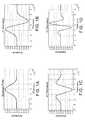
- FIG. 1Aillustrates a representative Gaussian Monocycle waveform in the time domain
- FIG. 1Billustrates the frequency domain amplitude of the Gaussian Monocycle of FIG. 1A
- FIG. 1Crepresents the second derivative of the Gaussian Monocycle of FIG. 1A;
- FIG. 1Drepresents the third derivative of the Gaussian Monocycle of FIG. 1A;
- FIG. 1Erepresents the Correlator Output vs. the Relative Delay in a real data pulse
- FIG. 1Fdepicts the frequency plot of the Gaussian family of the Gaussian Pulse and the first, second, and third derivative.
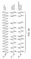
- FIG. 2Aillustrates a pulse train comprising pulses as in FIG. 1A;
- FIG. 2Billustrates the frequency domain amplitude of the waveform of FIG. 2A
- FIG. 2Cillustrates the pulse train spectrum
- FIG. 2Dis a plot of the Frequency vs. Energy Plot and points out the coded signal energy spikes
- FIG. 3Aillustrates representative signals of an interfering signal, a coded received pulse train and a coded reference pulse train
- FIG. 3Bdepicts a typical geometrical configuration giving rise to multipath received signals
- FIG. 3Cillustrates exemplary multipath signals in the time domain
- FIGS. 3D-3Fillustrate a signal plot of various multipath environments.
- FIG. 3Gillustrates the Rayleigh fading curve associated with non-impulse radio transmissions in a multipath environment.
- FIG. 3Hillustrates a plurality of multipaths with a plurality of reflectors from a transmitter to a receiver.
- FIG. 3Igraphically represents signal strength as volts vs. time in a direct path and multipath environment.
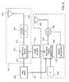
- FIG. 4illustrates a representative impulse radio transmitter functional diagram
- FIG. 5illustrates a representative impulse radio receiver functional diagram
- FIG. 6depicts an exemplary radar device
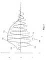
- FIG. 7illustrates the basic method according to the present invention
- FIG. 8Aillustrates a method of using a low-pass filter with a square law rectifying technique known in the prior art
- FIG. 8 Billustrates the envelope generated using the technique shown if FIG. 8A
- FIG. 9Adepicts the use of a Hilbert transform upon the received waveform
- FIG. 9Bdepicts the envelope generated using the technique shown in FIG. 9A
- FIG. 10Aillustrates the method of delaying the waveform according to the present invention
- FIG. 10Billustrates the envelope generated according to the present invention
- FIG. 11illustrates sub-sampling the waveform according to the present invention
- FIG. 12Aillustrates an exemplary detection geometry in accordance with the present invention
- FIG. 12Bdepicts sampling and delaying received waveforms in a radar device in accordance with the present invention
- FIG. 12Cdepicts in image generated in accordance with the present invention.
- FIG. 12Ddepicts an image not generated in accordance with the present invention.
- impulse radiois used primarily for historical convenience and that the terminology can be generally interchanged with the terminology ‘impulse system, ultra-wideband system, or ultra-wideband communication systems’. Furthermore, it should be understood that the described impulse radio technology is generally applicable to various other impulse system applications including but not limited to impulse radar systems and impulse positioning systems. Accordingly, the terminology ‘impulse radio’ can be generally interchanged with the terminology ‘impulse transmission system and impulse reception system.’
- Impulse radiorefers to a radio system based on short, low duty-cycle pulses.
- An ideal impulse radio waveformis a short Gaussian monocycle. As the name suggests, this waveform attempts to approach one cycle of radio frequency (RF) energy at a desired center frequency. Due to implementation and other spectral limitations, this waveform may be altered significantly in practice for a given application. Many waveforms having very broad, or wide, spectral bandwidth approximate a Gaussian shape to a useful degree.
- Impulse radiocan use many types of modulation, including amplitude modulation, phase modulation, frequency modulation, time-shift modulation (also referred to as pulse-position modulation or pulse-interval modulation) and M-ary versions of these.
- time-shift modulationalso referred to as pulse-position modulation or pulse-interval modulation
- M-ary versions of theseM-ary versions of these.
- the time-shift modulation methodis often used as an illustrative example.
- alternative modulation approachesmay, in some instances, be used instead of or in combination with the time-shift modulation approach.
- inter-pulse spacingmay be held constant or may be varied on a pulse-by-pulse basis by information, a code, or both.
- informationcomprising one or more bits of data typically time-position modulates a sequence of pulses. This yields a modulated, coded timing signal that comprises a train of pulses from which a typical impulse radio receiver employing the same code may demodulate and, if necessary, coherently integrate pulses to recover the transmitted information.
- the impulse radio receiveris typically a direct conversion receiver with a cross correlator front-end that coherently converts monocycle pulses to a baseband signal in a single stage.
- the baseband signalis the basic information signal for the impulse radio communications system.
- a subcarriermay also be included with the baseband signal to reduce the effects of amplifier drift and low frequency noise.
- the subcarrieralternately reverses modulation according to a known pattern at a rate faster than the data rate. This same pattern is used to reverse the process and restore the original data pattern just before detection.
- This methodpermits alternating current (AC) coupling of stages, or equivalent signal processing, to eliminate direct current (DC) drift and errors from the detection process. This method is described in more detail in U.S. Pat. No. 5,677,927 to Fullerton et al.
- Impulse transmission systemsare based on short, low duty-cycle pulses.
- Different pulse waveforms, or pulse typesmay be employed to accommodate requirements of various applications.
- Typical pulse typesinclude a Gaussian pulse, pulse doublet (also referred to as a Gaussian monocycle), pulse triplet, and pulse quadlet as depicted in FIGS. 1A through 1D, respectively.
- An actual received waveform that closely resembles the theoretical pulse quadletis shown in FIG. 1E.
- a pulse typemay also be a wavelet set produced by combining two or more pulse waveforms (e.g., a doublet/triplet wavelet set).
- These different pulse typesmay be produced by methods described in the patent documents referenced above or by other methods, as persons skilled in the art would understand.
- the transmitted waveform produced by supplying a step function into an ultra-wideband antennamay be modeled as a Gaussian monocycle.
- ⁇is a time scaling parameter
- tis time
- eis the natural logarithm base
- the power special density of the Gaussian monocycleis shown in FIG. 1F, along with spectrums for the Gaussian pulse, triplet, and quadlet.
- the output of an ultra-wideband antennais essentially equal to the derivative of its input Accordingly, since the pulse doublet, pulse triplet, and pulse quadlet are the first, second, and third derivatives of the Gaussian pulse, in an ideal model, an antenna receiving a Gaussian pulse will transmit a Gaussian monocycle and an antenna receiving a Gaussian monocycle will provide a pulse triplet.
- FIGS. 2A and 2Bare illustrations of the output of a typical 10 megapulses per second (Mpps) system with uncoded, unmodulated pulses, each having a width of 0.5 nanoseconds (ns).
- FIG. 2Ashows a time domain representation of the pulse train output.
- FIG. 2Billustrates that the result of the pulse train in the frequency domain is to produce a spectrum comprising a set of comb lines spaced at the frequency of the 10 Mpps pulse repetition rate.
- the envelope of the comb line spectrumcorresponds to the curve of the single Gaussian monocycle spectrum in FIG. 1 F.
- the power of the pulse trainis spread among roughly two hundred comb lines.
- Each comb linethus has a small fraction of the total power and presents much less of an interference problem to a receiver sharing the band.
- impulse transmission systemstypically have very low average duty cycles, resulting in average power lower than peak power.
- the duty cycle of the signal in FIG. 2Ais 0.5%, based on a 0.5 ns pulse duration in a 100 ns interval.
- jis the index of a pulse within a pulse train
- ( ⁇ 1) fis polarity (+/ ⁇ )
- ais pulse amplitude
- bis pulse type
- cis pulse width
- ⁇ (t, b)is the normalized pulse waveform
- T fis pulse repetition time
- A( ⁇ )is the amplitude of the spectral response at a given frequency
- ⁇is the frequency being analyzed (2 ⁇ f)
- ⁇ tis the relative time delay of each pulse from the start of time period
- nis the total number of pulses in the pulse train.
- a pulse traincan also be characterized by its autocorrelation and cross-correlation properties.
- Autocorrelation propertiespertain to the number of pulse coincidences (i.e., simultaneous arrival of pulses) that occur when a pulse train is correlated against an instance of itself that is offset in time.
- pulse coincidencesi.e., simultaneous arrival of pulses
- This ratiois commonly referred to as the main-lobe-to-side-lobe ratio, where the greater the ratio, the easier it is to acquire and track a signal.
- Cross-correlation propertiesinvolve the potential for pulses from two different signals simultaneously arriving, or coinciding, at a receiver. Of primary importance are the maximum and average numbers of pulse coincidences that may occur between two pulse trains. As the number of coincidences increases, the propensity for data errors increases. Accordingly, pulse train cross-correlation properties are used in determining channelization capabilities of impulse transmission systems (i.e., the ability to simultaneously operate within close proximity).
- Specialized coding techniquescan be employed to specify temporal and/or non-temporal pulse characteristics to produce a pulse train having certain spectral and/or correlation properties. For example, by employing a PN code to vary inter-pulse spacing, the energy in the comb lines presented in FIG. 2B can be distributed to other frequencies as depicted in FIG. 2D, thereby decreasing the peak spectral density within a bandwidth of interest. Note that the spectrum retains certain properties that depend on the specific (temporal) PN code used. Spectral properties can be similarly affected by using non-temporal coding (e.g., inverting certain pulses). Coding provides a method of establishing independent transmission channels. Specifically, families of codes can be designed such that the number of pulse coincidences between pulse trains produced by any two codes will be minimal. Generally, keeping the number of pulse collisions minimal represents a substantial attenuation of the unwanted signal.
- a codeconsists of a number of code elements having integer or floating-point values.
- a code element valuemay specie a single pulse characteristic or may be subdivided into multiple components, each specifying a different pulse characteristic.
- Code element or code component valuestypically map to a pulse characteristic value layout that may be fixed or non-fixed and may involve value ranges, discrete values, or a combination of value ranges and discrete values.
- a value range layoutspecifies a range of values that is divided into components that are each subdivided into subcomponents, which can be further subdivided, as desired.
- a discrete value layoutinvolves uniformly or non-uniformly distributed discrete values.
- a non-fixed layout(also referred to as a delta layout) involves delta values relative to some reference value.
- Impulse radio systems operating within close proximity to each othermay cause mutual interference. While coding minimizes mutual interference, the probability of pulse collisions increases as the number of coexisting impulse radio systems rises. Additionally, various other signals may be present that cause interference. Impulse radios can operate in the presence of mutual interference and other interfering signals, in part because they do not depend on receiving every transmitted pulse. Impulse radio receivers perform a correlating, synchronous receiving function (at the RF level) that uses statistical sampling and combining, or integration, of many pulses to recover transmitted information.
- 1 to 1000 or more pulsesare integrated to yield a single data bit thus diminishing the impact of individual pulse collisions, where the number of pulses that must be integrated to successfully recover transmitted information depends on a number of variables including pulse rate, bit rate, range and interference levels.
- impulse systemsBesides providing channelization and energy smoothing, coding makes impulse systems highly resistant to interference and jamming or spoofing by enabling discrimination between intended impulse transmissions and interfering transmissions. This property is desirable since impulse systems must share the energy spectrum with conventional radio systems and with other impulse systems.
- FIG. 3Aillustrates the result of a narrow band sinusoidal interference signal 302 overlaying an impulse radio signal 304 .
- the input to the cross correlationwould include the narrow band signal 302 and the received ultrawide-band impulse radio signal 304 .
- the inputis sampled by a correlator using a template signal 306 positioned in accordance with a code. Without coding, the correlation would sample the interfering signal 302 with such regularity that the interfering signals could cause interference to the impulse radio receiver. However, when the transmitted impulse signal is coded and the impulse radio receiver template signal 306 is synchronized using the identical code, the receiver samples the interfering signals non-uniformly.
- Impulse radio systemshave exceptional processing gain due to their wide spreading bandwidth.
- processing gainwhich quantifies the decrease in channel interference when wide-band communications are used, is the ratio of the bandwidth of the channel to the bit rate of the information signal.
- a direct sequence spread spectrum systemwith a 10 KHz information bandwidth and a 10 MHz channel bandwidth yields a processing gain of 1000, or 30 dB.
- far greater processing gainsare achieved by impulse radio systems, where the same 10 KHz information bandwidth is spread across a much greater 2 GHz channel bandwidth, resulting in a theoretical processing gain of 200,000, or 53 dB.
- N sis the number of pulses integrated per bit of information
- a kmodels the attenuation of transmitter k's signal over the propagation path to the receiver
- ⁇ rec 2is the variance of the receiver noise component at the pulse train integrator output.
- ⁇ (t)is the monocycle waveform
- ⁇is the time shift between the monocycle waveform and the template signal waveform
- T fis the pulse repetition time
- sis signal.
- impulse radiois its resistance to multipath fading effects.
- Conventional narrow band systemsare subject to multipath through the Rayleigh fading process, where the signals from many delayed reflections combine at the receiver antenna according to their seemingly random relative phases resulting in possible summation or possible cancellation, depending on the specific propagation to a given location.
- Multipath fading effectsare most adverse where a direct path signal is weak relative to multipath signals, which represents the majority of the potential coverage area of a radio system.
- received signal strengthfluctuates due to the changing mix of multipath signals that vary as its position varies relative to fixed transmitters, mobile transmitters and signal-reflecting surfaces in the environment.
- FIG. 3Billustrates a typical multipath situation, such as in a building, where there are many reflectors 304 B, 305 B.
- a transmitter 306 Btransmits a signal that propagates along three paths, the direct path 301 B, path 1 302 B, and path 2 303 B, to a receiver 308 B, where the multiple reflected signals are combined at the antenna.
- the direct path 301 Brepresenting the straight-line distance between the transmitter and receiver, is the shortest.
- Path 1 302 Brepresents a multipath reflection with a distance very close to that of the direct path.
- Path 2 303 Brepresents a multipath reflection with a much longer distance. Also shown are elliptical (or, in space, ellipsoidal) traces that represent other possible locations for reflectors that would produce paths having the same distance and thus the same time delay.
- FIG. 3Cillustrates the received composite pulse waveform resulting from the three propagation paths 301 B, 302 B, and 303 B shown in FIG. 3 B.
- the direct path signal 301 Bis shown as the first pulse signal received.
- the path 1 and path 2 signals 302 B, 303 Bcomprise the remaining multipath signals, or multipath response, as illustrated.
- the direct path signalis the reference signal and represents the shortest propagation time.
- the path 1 signalis delayed slightly and overlaps and enhances the signal strength at this delay value.
- the path 2 signalis delayed sufficiently that the waveform is completely separated from the direct path signal. Note that the reflected waves are reversed in polarity.
- the path 2 signalwill not be sampled and thus will produce no response.
- the path 1 signalhas an effect on the reception of the direct path signal since a portion of it would also be sampled by the template signal.
- multipath signals delayed less than one quarter wavemay attenuate the direct path signal. This region is equivalent to the first Fresnel zone in narrow band systems.
- Impulse radiohas no further nulls in the higher Fresnel zones. This ability to avoid the highly variable attenuation from multipath gives impulse radio significant performance advantages.
- FIGS. 3D, 3 E, and 3 Frepresent the received signal from a TM-UWB transmitter in three different multipath environments. These figures are approximations of typical signal plots.
- FIG. 3Dillustrates the received signal in a very low multipath environment This may occur in a building where the receiver antenna is in the middle of a room and is a relatively short, distance, for example, one meter, from the transmitter. This may also represent signals received from a larger distance, such as 100 meters, in an open field where there are no objects to produce reflections. In this situation, the predominant pulse is the first received pulse and the multipath reflections are too weak to be significant.
- FIG. 3Eillustrates an intermediate multipath environment. This approximates the response from one room to the next in a building.
- the amplitude of the direct path signalis less than in FIG. 3 D and several reflected signals are of significant amplitude.
- FIG. 3Fapproximates the response in a severe multipath environment such as propagation through many rooms, from corner to corner in a building, within a metal cargo hold of a ship, within a metal truck trailer, or within an intermodal shipping container.
- the main path signalis weaker than in FIG. 3 E.
- the direct path signal poweris small relative to the total signal power from the reflections.
- An impulse radio receivercan receive the signal and demodulate the information using either the direct path signal or any multipath signal peak having sufficient signal-to-noise ratio.
- the impulse radio receivercan select the strongest response from among the many arriving signals.
- the multipath signalsIn order for the multipath signals to cancel and produce a null at a given location, dozens of reflections would have to be cancelled simultaneously and precisely while blocking the direct path, which is a highly unlikely scenario.
- This time separation of multipath signals together with time resolution and selection by the receiverpermit a type of time diversity that virtually eliminates cancellation of the signal.
- performanceis further improved by collecting the signal power from multiple signal peaks for additional signal-to-noise performance.
- the received signalis a sum of a large number of sine waves of random amplitude and phase.
- ris the envelope amplitude of the combined multipath signals
- ⁇ (2) 1 ⁇ 2is the RMS power of the combined multipath signals.
- the Rayleigh distribution curve in FIG. 3Gshows that 10% of the time, the signal is more than 10 dB attenuated. This suggests that 10 dB fade margin is needed to provide 90% link availability. Values of fade margin from 10 to 40 dB have been suggested for various narrow band systems, depending on the required reliability. This characteristic has been the subject of much research and can be partially improved by such techniques as antenna and frequency diversity, but these techniques result in additional complexity and cost.
- FIG. 3Hdepicts an impulse radio system in a high multipath environment 300 H consisting of a transmitter 306 H and a receiver 308 H.
- a transmitted signalfollows a direct path 301 H and reflects off reflectors 303 H via multiple paths 302 H.
- FIG. 3Iillustrates the combined signal received by the receiver 308 H over time with the vertical axis being signal strength in volts and the horizontal axis representing time in nanoseconds.
- the direct path 301 Hresults in the direct path signal 302 I while the multiple paths 302 H result in multipath signals 304 I.
- the direct path signal 302 Iis sampled, while the multipath signals 304 I are not, resulting in Rayleigh fading avoidance.
- An exemplary embodiment of an impulse radio transmitter 402 of an impulse radio communication system having an optional subcarrier channelwill now be described with reference to FIG. 4 .
- the transmitter 402comprises a time base 404 that generates a periodic timing signal 406 .
- the time base 404typically comprises a voltage controlled oscillator (VCO), or the like, having a high timing accuracy and low jitter, on the order of picoseconds (ps).
- VCOvoltage controlled oscillator
- the control voltage to adjust the VCO center frequencyis set at calibration to the desired center frequency used to define the transmitters nominal pulse repetition rate.
- the periodic timing signal 406is supplied to a precision timing generator 408 .
- the precision timing generator 408supplies synchronizing signals 410 to the code source 412 and utilizes the code source output 414 , together with an optional, internally generated subcarrier signal, and an information signal 416 , to generate a modulated, coded timing signal 418 .
- An information source 420supplies the information signal 416 to the precision timing generator 408 .
- the information signal 416can be any type of intelligence, including digital bits representing voice, data, imagery, or the like, analog signals, or complex signals.
- a pulse generator 422uses the modulated, coded timing signal 418 as a trigger signal to generate output pulses.
- the output pulsesare provided to a transmit antenna 424 via a transmission line 426 coupled thereto.
- the output pulsesare converted into propagating electromagnetic pulses by the transmit antenna 424 .
- the electromagnetic pulsesare called the emitted signal, and propagate to an impulse radio receiver 502 , such as shown in FIG. 5, through a propagation medium.
- the emitted signalis wide-band or ultra wideband, approaching a monocycle pulse as in FIG. 1 B.
- the emitted signalmay be spectrally modified by filtering of the pulses, which may cause them to have more zero crossings (more cycles) in the time domain, requiring the radio receiver to use a similar waveform as the template signal for efficient conversion.
- an exemplary embodiment of an impulse radio receiver (hereinafter called the receiver) for the impulse radio communication systemis now described with reference to FIG. 5 .
- the receiver 502comprises a receive antenna 504 for receiving a propagated impulse radio signal 506 .
- a received signal 508is input to a cross correlator or sampler 510 , via a receiver transmission line, coupled to the receive antenna 504 .
- the cross correlation 510produces a baseband output 512 .
- the receiver 502also includes a precision timing generator 514 , which receives a periodic timing signal 516 from a receiver time base 518 .
- This time base 518may be adjustable and controllable in time, frequency, or phase, as required by the lock loop in order to lock on the received signal 508 .
- the precision timing generator 514provides synchronizing signals 520 to the code source 522 and receives a code control signal 524 from the code source 522 .
- the precision timing generator 514utilizes the periodic timing signal 516 and code control signal 524 to produce a coded timing signal 526 .
- the template generator 528is triggered by this coded timing signal 526 and produces a train of template signal pulses 530 ideally having waveforms substantially equivalent to each pulse of the received signal 508 .
- the code for receiving a given signalis the same code utilized by the originating transmitter to generate the propagated signal.
- the timing of the template pulse trainmatches the timing of the received signal pulse train, allowing the received signal 508 to be synchronously sampled in the correlator 510 .
- the correlator 510preferably comprises a multiplier followed by a short term integrator to sum the multiplier product over the pulse interval.
- the output of the correlator 510is coupled to a subcarrier demodulator 532 , which demodulates the subcarrier information signal from the optional subcarrier.
- the purpose of the optional subcarrier process, when used,is to move the information signal away from DC (zero frequency) to improve immunity to low frequency noise and offsets.
- the output of the subcarrier demodulatoris then filtered or integrated in the pulse summation stage 534 .
- a digital system embodimentis shown in FIG. 5 .
- a sample and hold 536samples the output 535 of the pulse summation stage 534 synchronously with the completion of the summation of a digital bit or symbol.
- the output of sample and hold 536is then compared with a nominal zero (or reference) signal output in a detector stage 538 to provide an output signal 539 representing the digital state of the output voltage of sample and hold 536 .
- the baseband signal 512is also input to a lowpass filter 542 (also referred to as lock loop filter 542 ).
- a control loopcomprising the lowpass filter 542 , time base 518 , precision timing generator 514 , template generator 528 , and correlator 510 is used to generate an error signal 544 .
- the error signal 544provides adjustments to the adjustable time base 518 to position in time the periodic timing signal 526 in relation to the position of the received signal 508 .
- transceiver embodimentsubstantial economy can be achieved by sharing part or all of several of the functions of the transmitter 602 and receiver 502 . Some of these include the time base 518 , precision timing generator 514 , code source 522 , antenna 504 , and the like.
- a transmit component 601is comprised of a timing base 605 that provides a precise timing signal 607 coupled to a transmitting precision timing generator 610 which positions individual pulses in time in accordance with a signal from a pseudo-noise code source 615 .
- the depicted architecturedoes not show an information source 420 shown in FIG. 4, however, it should be noted that data could be modulated for transmission in the outgoing signal.
- the timing generator output 612is received by a pulse generator 620 which generates the impulse signal 625 that is sent to the transmitting antenna 630 for conversion to an emitted signal.
- the same timing meansprovides timing control for the receive component 602 as well.
- the same time base 605is coupled to a receive-side precision timing generator 635 which positions individual sampling pulses in time.
- the receive-side precision timing generator 635also receives a signal from the pseudo-noise code source 615 .
- a timing delay 640is also fed to the receive-side precision timing generator 635 to delay the output some ⁇ t with respect to the transmitted signal in order to develop the necessary ranging information from the return waveforms.
- This signal 642is output to a correlator 645 , or mixer, or sampler, which samples the signal received from the receiving antenna 650 .
- the result of the correlation stepis sent to a signal processor for range and azimuth determination.
- FIG. 7is an exemplary received impulse waveform 700 , as the term is used above, such impulse waveform having wideband or ultra-wideband properties. It is observed that for all impulse waveforms the fundamental structure is that of an amplitude modulated sinusoidal wave. The amplitude modulation produces an amplitude envelope 702 which generally approximates a Gaussian function, the temporal duration of which is approximately inversely proportional to the total bandwidth of the impulse waveform 700 . Deviations from the ideal Gaussian envelope occur due to the details of the hardware implementation and the spectral shaping requirements of the specific application.
- the sinusoidal component of the impulse waveform 700has a dominant periodicity which is inversely proportional to the center frequency of the impulse waveform spectrum, said center frequency consisting of a weighted average of the frequency spectrum of the impulse waveform 700 .
- the present methoddetermines a peak-to-zero delay (PZD) interval 704 , by finding the time at which greatest waveform amplitude occurs 708 and the time at which the next-occurring point when the waveform energy is zero 712 . The difference between those times is the PZD interval 704 .
- the intervalcould also be determined using a measurement of the times between a zero-crossing and a peak as well. Likewise, the interval could be measured between a negative displacement with the greatest magnitude and the next-occurring zero-crossing.
- the term “PZD interval”will mean any of these three values.
- the received impulse waveform 700is duplicated and delayed by the PZD interval 704 to make a delayed waveform 716 .
- a detection envelope 720is then calculated by squaring the received impulse waveform 700 and the PZD delayed waveform 716 . These are summed and the square root is taken yielding the definition of the envelope 720 .
- the ratio of the temporal period corresponding to the center frequency of the ultra-wideband signal 700 divided by the PZD interval 704is approximately equal to four.
- CWcontinuous wave
- I/Qin-phase and quadrature
- this analogycan not be used directly in the context of UWB signals for the majority of the band of the UWB signal.
- True I/Q datais collected by stepped frequency radars or network analyzers that use true sine and cosine waves over the entire band to down convert the RF signal.
- the low pass filter methoduses square law detection to rectify the received waveform and then applies a low pass filter to remove the high frequency components.
- the high frequency componentsare usually associated with the carrier frequency in CW systems.
- the Hilbert Transform methodproduces a new waveform from the original waveform which is 90 degrees out of phase with the original waveform.
- Nyquistdemonstrated that a signal needs to be sampled at a rate twice the highest frequency of interest in order to retain all of the information. This is known in the art as the Nyquist rate.
- signal processingworks better when the Nyquist rate is exceeded, in other words, when the waveform is over sampled, often by a factor of two to four times the Nyquist rate.
- the waveformdoes not have to be sampled at a rate greater than the Nyquist rate yet the PZD method produces an image free of ambiguous nulls due to AC canceling effects.
- processing costin terms of capacity, throughput, time and money, is significantly reduced.
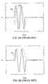
- FIG. 8Adepicts a received waveform 804 and a delayed rectified waveform 808 created by rectifying the received waveform 804 .
- an envelope 812is created by applying a low pass filter to the rectified waveform 808 .
- FIG. 9Ashows a received waveform 904 paired with its Hilbert transform waveform 908 .
- the envelope 912 of the waveform 904was created by taking the square root of the sum of the squares of the received waveform 904 and its Hilbert transform 908 . In this case, the waveform from the Hilbert transform would be treated just like a delayed waveform.
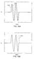
- FIG. 10Ashows the raw waveform 1004 and its associated peak-zero delayed waveform 1008 .
- the square root of the sum of the squares of these two waveformsis used to generate the envelope 1012 shown in FIG. 10 B.
- the result using the PZD envelope detection methodyields the best results in terms of pulse width and ripple for this ideal pulsed sinusoid example. Note that these results can be achieved without excessive over sampling above the Nyquist rate.
- ripplesdo occur depending upon which lobe in the waveform is being processed because the peak-zero delay interval tends to change slightly across the waveform as a result of frequency dispersion. However, these ripples are usually minor and do not detract from producing an envelope which is highly representative of the true envelope.
- a PZD intervalmay be chosen by measuring some or all of peak-to-zero and/or zero-to-peak intervals and finding the mean value or a median value of the measured intervals. This, of course, depends upon whether such extra processing is feasible given processing and memory capacity of the apparatus. It may be preferable that if many intervals are measured, a median value is used because of the effects of outlier interval values on the average value.
- a significant advantage of PZD processing techniquesis the ability to sub-sample the data in an image generation process such as Synthetic Aperture Radar (SAR) imaging.
- SARSynthetic Aperture Radar
- the imagewould need to have a sample spacing on the order of the Nyquist frequency in both dimensions of a uniform resolution image.
- the required image arraycan be much smaller in many instances.
- FIG. 11shows an exemplary received UWB impulse waveform 1104 .
- the waveformis periodically sampled at each sampling point 1106 . It is assumed that these samples occur such that Nyquist sampling rate is exceeded by a factor of 2 (i.e. a minimum of 4 samples across a single cycle of waveform 1104 ) or any multiple thereof.
- the samples 1106must be close together in order to retain the frequency information unambiguously which drives the cross range resolution. If an image were formed from the set of all samples from the waveform 1104 , a large array would be necessary for data processing, potentially much larger than required to meet the resolution requirements. Alternatively this large array may be larger than the number of available pixels for many display applications, such as handheld devices.
- the waveformcan be subsampled, i.e., sampled at a rate less than the Nyquist rate.
- the sampling ratewould then be commensurate with the resolution requirement for the application or the display resolution capability while still accurately measuring the PZD envelope at the desired point in the image.
- first P sample 1108 a and first Z sample 1108 bmay be used in each received waveform to define one boundary of the envelope of the image.
- a second pair, shown as second P sample 1110 a and second Z sample 1110 bdefine a second boundary.
- an envelope 1112is generated using the PZD pairs 1108 a,b and 1110 a,b. Display pixels may be illuminated between the points corresponding to these pairs.
- the envelope-detected imagehas a much lower sampling requirement than the waveform itself. More pairs may be used, however, two pairs is generally sufficient. Therefore, image generation speed would benefit from a technique that requires less data to be processed.
- multiple received waveforms 700are used to create an envelope-detected image of the object.
- the description that followscorresponds to the geometry shown in FIG. 12A, wherein radar device 1201 , illuminates and detects moving object 1202 (a moving human for example).
- An angle and distance from the object 1202 to the antenna array centroid 1203defines a radial 1200 .
- Similar radialsmay be defined from the object 1202 to each of the antenna elements depicted on antenna array 1203 .
- these antenna elementsmay consist of a pair of elements, one element being for transmitting the UWB waveform 700 and the other element being for receiving the UWB waveform 700 .
- a single elementmay act to both transmit and receive a UWB waveform 700 . In either case, there exist unique radials between each object 1202 and each antenna element.
- a plurality of waveforms 1204 a-hare received, each waveform 1204 a-h being shifted in time proportional to the range from the object reflecting the energy to each antenna receive element 1205 a-h of an antenna array.
- waveforms 1204 a-hcan be received along multiple radials from different objects located at different positions to the antenna array receive elements 1205 a-h.
- FIG. 12Bshows only a representative set of waveforms 1204 a-h, received from the direction of a single radial 1200 . The method described hereafter is therefore applicable across all such radials.
- a waveform sample 1208 a-h corresponding to an image pixelis selected on each of the waveforms 1204 a-h.
- the waveform sample 1208 arelates to a range from the object to the antenna 1205 a.
- Corresponding waveform samples 1208 b-h on each of the waveforms 1204 b-his likewise sampled.
- An intermediate imageis then generated by summing the waveform samples 1208 a-h of each waveform 1204 a-h, and squaring this sum. This value will be referred to as the P value.
- Each waveform 1204 a-his duplicated and delayed uniformly by the PZD interval 1210 .
- the delaymay be effected by delaying each waveform 1204 a-h separately, or, preferably, delayed simultaneously. Additionally, the waveform samples 1208 a-h maybe delayed in time to ease processing costs.
- FIG. 12Bshows delayed waveforms 1212 a-h. Delayed waveform samples 1216 a-h, again corresponding to image pixels, are selected in the delayed waveforms 1212 a-h.
- a Z intermediate imageis generated by summing the delayed waveform samples 1216 a-h of each delayed waveform 1212 a-h, and squaring this sum. This value is referred to as the Z value.
- An image of the entire PZD envelopeis generated by adding the Z value and the P value and taking the square root The square root can be eliminated if the desire is to depict an image corresponding to power instead of voltage.
- FIG. 12Cshows the net result is an image 1210 shown on an exemplary image display 1230 where the detected object is represented by a more intuitive shape.
- FIG. 12Dshows the image 1250 of a detected object displayed on an exemplary image display 1240 , said image being generated without using the PZD technique. Nulls 1255 a, 1255 b, 1255 c and 1255 d are shown.
- the PZD techniqueis applicable to both synthetically scanned radars and to radar systems with a mechanically or electrically scanned antennas. Further, as would be apparent to those skilled in the art, these above-described techniques would be applicable to devices that employ a single transmit/receive antenna pair or a single switched transmit and receive antenna element where the device is moved to generate a synthetic aperture, or in any device where image processing uses time versus device position plots.
- PZD processingmay also be beneficially employed in less sophisticated sensors such as proximity detectors that are used in applications like stud-finding and motion detectors. Because of the reduced processing and storage requirement, such devices may be made for less cost.
- ranges 1 and 2are monitored by two different PZD pairs.
- Coupling the PZD processing with a sparse samplingcan yield a well-behaved system response that can be easily sent to the threshold detector.
- Using multiple thresholdsallows a level of target classification. For example, a stud finder may discriminate between a wood stud and a metal blocking plate due to the metal plate producing a much larger variation. Further classification can be extracted by monitoring two regions in order to extract coarse depth information which may help discriminate between a wood stud against drywall and a copper pipe that is in the middle of the wall. Yet, variations in the dielectric and varying thickness of different building materials are slight enough that the envelope detection is adequate to detect a stud using a single PZD pair.
- this timingis phase shift based, and therefore provides only relative timing and is subject to the ambiguity from the multiple lobes of the pulse.
- phase processingwould be very applicable to monitoring small movements such as breathing for remote patient observation.
- the changes in the phase anglecould be filtered to define the respiratory rate.
- use of this approachallows a cost sensitive system to monitor a very small number of ranges and effectively detect the desired response without having the periodic nulling associated with the target's response. This benefits the system by eliminating the need for variable or programmable delays and replacing them with a couple of fixed delays.
- the present inventioncomprises a method for image envelope generation of an object reflecting ultra wideband signals. While particular embodiments of the invention have been described, it will be understood, however, that the invention is not limited thereto, since modifications may be made by those skilled in the art, particularly in light of the foregoing teachings. It is, therefore, contemplated by the appended claims to cover any such modifications that incorporate those features or those improvements that embody the spirit and scope of the present invention.
Landscapes
- Engineering & Computer Science (AREA)
- Radar, Positioning & Navigation (AREA)
- Remote Sensing (AREA)
- Computer Networks & Wireless Communication (AREA)
- Physics & Mathematics (AREA)
- General Physics & Mathematics (AREA)
- Radar Systems Or Details Thereof (AREA)
Abstract
Description


Claims (8)
Priority Applications (1)
| Application Number | Priority Date | Filing Date | Title |
|---|---|---|---|
| US10/083,191US6552677B2 (en) | 2001-02-26 | 2002-02-26 | Method of envelope detection and image generation |
Applications Claiming Priority (2)
| Application Number | Priority Date | Filing Date | Title |
|---|---|---|---|
| US27149901P | 2001-02-26 | 2001-02-26 | |
| US10/083,191US6552677B2 (en) | 2001-02-26 | 2002-02-26 | Method of envelope detection and image generation |
Publications (2)
| Publication Number | Publication Date |
|---|---|
| US20020175850A1 US20020175850A1 (en) | 2002-11-28 |
| US6552677B2true US6552677B2 (en) | 2003-04-22 |
Family
ID=26769030
Family Applications (1)
| Application Number | Title | Priority Date | Filing Date |
|---|---|---|---|
| US10/083,191Expired - LifetimeUS6552677B2 (en) | 2001-02-26 | 2002-02-26 | Method of envelope detection and image generation |
Country Status (1)
| Country | Link |
|---|---|
| US (1) | US6552677B2 (en) |
Cited By (74)
| Publication number | Priority date | Publication date | Assignee | Title |
|---|---|---|---|---|
| US20030232612A1 (en)* | 2002-06-14 | 2003-12-18 | Richards James L. | Method and apparatus for converting RF signals to baseband |
| US20050128124A1 (en)* | 2003-12-12 | 2005-06-16 | Greneker Eugene F.Iii | Radar detection device employing a scanning antenna system |
| US20050194959A1 (en)* | 2004-03-04 | 2005-09-08 | Zircon Corporation | Ratiometric stud sensing |
| US20050213635A1 (en)* | 2004-01-30 | 2005-09-29 | Semiconductor Technology Academic Research Center | Ultra-wideband receiver |
| US20050253597A1 (en)* | 2004-05-14 | 2005-11-17 | Zircon Corporation | Auto-deep scan for capacitive sensing |
| US20060233046A1 (en)* | 2005-04-14 | 2006-10-19 | Fluhler Herbert U | Apparatus for effecting surveillance of a space beyond a barrier |
| US20060233045A1 (en)* | 2005-04-14 | 2006-10-19 | Fluhler Herbert U | Apparatus for effecting acoustic surveillance of a space beyond a barrier |
| US20070147476A1 (en)* | 2004-01-08 | 2007-06-28 | Institut De Microtechnique Université De Neuchâtel | Wireless data communication method via ultra-wide band encoded data signals, and receiver device for implementing the same |
| US20070162964A1 (en)* | 2006-01-12 | 2007-07-12 | Wang Liang-Yun | Embedded system insuring security and integrity, and method of increasing security thereof |
| US20070183535A1 (en)* | 2001-03-26 | 2007-08-09 | Irena Maravic | Sampling method for a spread spectrum communication system |
| WO2006026401A3 (en)* | 2004-08-27 | 2007-09-20 | L 3 Comm Security & Detection | Method and apparatus to detect event signatures |
| US20070242026A1 (en)* | 2006-04-14 | 2007-10-18 | Qualcomm Incorporated | Apparatus and method of pulse generation for ultra-wideband transmission |
| US20070248114A1 (en)* | 2006-04-20 | 2007-10-25 | Qualcomm Incorporated | Media access control for ultra-wide band communication |
| US20070249288A1 (en)* | 2006-04-14 | 2007-10-25 | Kamran Moallemi | Distance-based security |
| US20070259662A1 (en)* | 2006-04-26 | 2007-11-08 | Qualcomm Incorporated | Wireless device communication with multiple peripherals |
| US20070259690A1 (en)* | 2006-04-14 | 2007-11-08 | Qualcomm Incorporated | Distance-based presence management |
| US20070257827A1 (en)* | 2006-04-20 | 2007-11-08 | Qualcomm Incorporated | Low power output stage |
| US20070279237A1 (en)* | 2006-04-26 | 2007-12-06 | Qualcomm Incorporated | Wireless localization apparatus and method |
| US20070281721A1 (en)* | 2006-04-26 | 2007-12-06 | Qualcomm Incorporated | Methods and apparatuses of initiating communication in wireless networks |
| US20070287386A1 (en)* | 2006-04-14 | 2007-12-13 | Qualcomm Incorporated | Distance-based association |
| US20070285306A1 (en)* | 2006-04-18 | 2007-12-13 | Qualcomm Incorporated | Verified distance ranging |
| US20080043824A1 (en)* | 2006-04-18 | 2008-02-21 | Qualcomm Incorporated | Offloaded processing for wireless applications |
| US20080117939A1 (en)* | 2006-11-16 | 2008-05-22 | Qualcomm Incorporated | Multiple access techniques for a wireless communiation medium |
| US20080117804A1 (en)* | 2006-11-16 | 2008-05-22 | Qualcomm Incorporated | Multiple access techniques for a wireless communication medium |
| US20080116941A1 (en)* | 2006-11-16 | 2008-05-22 | Qualcomm Incorporated | Peak signal detector |
| US20080144560A1 (en)* | 2006-12-15 | 2008-06-19 | Qualcomm Incorporated | Channel access scheme for ultra-wide band communication |
| WO2008063691A3 (en)* | 2006-04-12 | 2008-07-10 | Univ Rice William M | Apparatus and method for compressive sensing radar imaging |
| US20080183289A1 (en)* | 2007-01-29 | 2008-07-31 | Werblin Research & Development Corp. | Intraocular lens system |
| US20080240440A1 (en)* | 2007-03-27 | 2008-10-02 | Gregory Gordon Rose | Synchronization test for device authentication |
| US20080246548A1 (en)* | 2007-04-05 | 2008-10-09 | Qualcomm Incorporated | Method and apparatus for generating oscillating signals |
| US20080262928A1 (en)* | 2007-04-18 | 2008-10-23 | Oliver Michaelis | Method and apparatus for distribution and personalization of e-coupons |
| US20080258562A1 (en)* | 2007-04-23 | 2008-10-23 | Qualcomm Incorporated | Apparatus and method for generating fine timing from coarse timing source |
| US20090016548A1 (en)* | 2007-07-10 | 2009-01-15 | Pavel Monat | Super regenerative (sr) apparatus having plurality of parallel sr amplifiers tuned to distinct frequencies |
| US20090017782A1 (en)* | 2007-07-12 | 2009-01-15 | Pavel Monat | Method for determining line-of-sight (los) distance between remote communications devices |
| US20090021408A1 (en)* | 2007-07-18 | 2009-01-22 | Lee Chong U | Adaptive dynamic range control |
| US20090034591A1 (en)* | 2007-07-30 | 2009-02-05 | David Jonathan Julian | Method of pairing devices |
| US20090061777A1 (en)* | 2007-08-28 | 2009-03-05 | Qualcomm Incorporated | Apparatus and method for modulating an amplitude, phase or both of a periodic signal on a per cycle basis |
| US20090067407A1 (en)* | 2007-09-11 | 2009-03-12 | Qualcomm Incorporated | Keep-alive for wireless networks |
| US20090076911A1 (en)* | 2007-06-20 | 2009-03-19 | Dang Minh Vo | Mobile coupons utilizing peer to peer ranging |
| US20090076912A1 (en)* | 2007-06-20 | 2009-03-19 | Rajan Rajeev D | Management of dynamic electronic coupons |
| US20090080101A1 (en)* | 2007-09-21 | 2009-03-26 | Qualcomm Incorporated | Signal generator with adjustable frequency |
| US20090080542A1 (en)* | 2007-09-25 | 2009-03-26 | Qualcomm Incorporated | Interference Mitigation For Impulse-Based Communication |
| US20090080568A1 (en)* | 2007-09-21 | 2009-03-26 | Qualcomm Incorporated | Signal generator with adjustable phase |
| US20090086702A1 (en)* | 2007-09-28 | 2009-04-02 | Qualcomm Incorporated | Randomization of periodic channel scans |
| US20090224832A1 (en)* | 2008-03-10 | 2009-09-10 | Qualcomm Incorporated | System and method of enabling a signal processing device in a relatively fast manner to process a low duty cycle signal |
| US20090224860A1 (en)* | 2008-03-10 | 2009-09-10 | Qualcomm Incorporated | System and method of using residual voltage from a prior operation to establish a bias voltage for a subsequent operation |
| US20090243699A1 (en)* | 2008-03-25 | 2009-10-01 | Qualcomm Incorporated | System and method of companding an input signal of an energy detecting receiver |
| US20090251208A1 (en)* | 2008-04-08 | 2009-10-08 | Qualcomm Incorporated | Low power slicer-based demodulator for ppm |
| US20090259672A1 (en)* | 2008-04-15 | 2009-10-15 | Qualcomm Incorporated | Synchronizing timing mismatch by data deletion |
| US20090270030A1 (en)* | 2008-04-23 | 2009-10-29 | Qualcomm Incorporated | Multi-level duty cycling |
| US20090323985A1 (en)* | 2008-06-30 | 2009-12-31 | Qualcomm Incorporated | System and method of controlling power consumption in response to volume control |
| US20100020863A1 (en)* | 2008-07-25 | 2010-01-28 | Qualcomm Incorporated | Determination of receive data values |
| US20100046443A1 (en)* | 2008-08-22 | 2010-02-25 | Qualcomm Incorporated | Addressing schemes for wireless communication |
| US7716001B2 (en) | 2006-11-15 | 2010-05-11 | Qualcomm Incorporated | Delay line calibration |
| US20100157886A1 (en)* | 2007-10-26 | 2010-06-24 | Qualcomm Incorporated | Preamble capture and medium access control |
| US20100172393A1 (en)* | 2009-01-06 | 2010-07-08 | Qualcomm Incorporated | Pulse arbitration for network communications |
| US20100241816A1 (en)* | 2009-03-19 | 2010-09-23 | Qualcolmm Incorporated | Optimized transfer of packets in a resource constrained operating environment |
| US7855611B2 (en) | 2006-11-15 | 2010-12-21 | Qualcomm Incorporated | Delay line calibration |
| US7965805B2 (en) | 2007-09-21 | 2011-06-21 | Qualcomm Incorporated | Signal generator with signal tracking |
| US20110231657A1 (en)* | 2009-03-16 | 2011-09-22 | Qualcomm Incorporated | Apparatus and method for employing codes for telecommunications |
| CN101762808B (en)* | 2010-01-15 | 2012-01-25 | 山东大学 | Method for extracting radar pulse based on self-adaption threshold value |
| US8375261B2 (en) | 2008-07-07 | 2013-02-12 | Qualcomm Incorporated | System and method of puncturing pulses in a receiver or transmitter |
| US8483639B2 (en) | 2008-05-06 | 2013-07-09 | Qualcomm Incorporated | AGC for slicer-based low power demodulator |
| US8514911B2 (en) | 2009-05-13 | 2013-08-20 | Qualcomm Incorporated | Method and apparatus for clock drift compensation during acquisition in a wireless communication system |
| US8538345B2 (en) | 2007-10-09 | 2013-09-17 | Qualcomm Incorporated | Apparatus including housing incorporating a radiating element of an antenna |
| US8600373B2 (en) | 2006-04-26 | 2013-12-03 | Qualcomm Incorporated | Dynamic distribution of device functionality and resource management |
| US8811456B2 (en) | 2006-04-19 | 2014-08-19 | Qualcomm Incorporated | Apparatus and method of low latency multi-hop communication |
| US20140320336A1 (en)* | 2007-08-31 | 2014-10-30 | Raymarine Uk Limited | Digital radar or sonar apparatus |
| CN104168458A (en)* | 2014-08-18 | 2014-11-26 | 北京世纪之星应用技术研究中心 | Optical invasion detection method and system and distributed monitoring system |
| US9141961B2 (en) | 2007-06-20 | 2015-09-22 | Qualcomm Incorporated | Management of dynamic mobile coupons |
| US9191254B2 (en) | 2012-03-29 | 2015-11-17 | Samsung Electronics Co., Ltd. | Method and apparatus for detecting envelope using difference between sampling signals |
| US9291711B2 (en)* | 2010-02-25 | 2016-03-22 | University Of Maryland, College Park | Compressive radar imaging technology |
| US9483769B2 (en) | 2007-06-20 | 2016-11-01 | Qualcomm Incorporated | Dynamic electronic coupon for a mobile environment |
| US10542372B2 (en) | 2011-03-15 | 2020-01-21 | Qualcomm Incorporated | User identification within a physical merchant location through the use of a wireless network |
Families Citing this family (21)
| Publication number | Priority date | Publication date | Assignee | Title |
|---|---|---|---|---|
| US6919838B2 (en)* | 2001-11-09 | 2005-07-19 | Pulse-Link, Inc. | Ultra-wideband imaging system |
| US6650272B2 (en)* | 2002-01-16 | 2003-11-18 | Raytheon Company | Radar system and method |
| US7082153B2 (en)* | 2002-09-23 | 2006-07-25 | Lucent Technologies Inc. | Variable spacing pulse position modulation for ultra-wideband communication links |
| KR100501937B1 (en)* | 2003-05-03 | 2005-07-18 | 삼성전자주식회사 | Ultra wideband transceiver and method thereof |
| US6806821B2 (en)* | 2003-03-12 | 2004-10-19 | Itt Manufacturing Enterprises, Inc. | Apparatus and method for rapid detection of objects with time domain impulsive signals |
| FR2871241B1 (en)* | 2004-06-07 | 2007-01-26 | Commissariat Energie Atomique | ULB LOCATION SYSTEM FOR AVALANCHES VICTIMS RELIEF |
| WO2006080006A1 (en)* | 2005-01-26 | 2006-08-03 | Gamma Medica-Ideas (Norway) As | Video-rate holographic surveillance system |
| JP2009049677A (en)* | 2007-08-20 | 2009-03-05 | Seiko Epson Corp | Pulse receiving circuit and pulse radio communication apparatus |
| RU2369323C1 (en)* | 2008-02-20 | 2009-10-10 | Игорь Яковлевич Иммореев | Impulse superwide-band sensor |
| US8212710B2 (en) | 2008-10-31 | 2012-07-03 | Raytheon Company | Radar image generation system |
| US8730085B2 (en)* | 2010-08-26 | 2014-05-20 | Lawrence Livermore National Security, Llc | Spot restoration for GPR image post-processing |
| US9372259B2 (en)* | 2011-08-12 | 2016-06-21 | Panasonic Corporation | Radar apparatus |
| KR101779829B1 (en)* | 2011-10-07 | 2017-10-11 | 삼성전자주식회사 | Apparatus and method for envelope detection |
| US9532735B2 (en)* | 2013-10-23 | 2017-01-03 | King Abdullah University Of Science And Technology | Apparatus and method for wireless monitoring using ultra-wideband frequencies |
| US9778678B2 (en)* | 2015-08-19 | 2017-10-03 | International Business Machines Corporation | Method and apparatus for clocked data eye measurement |
| CN107167771B (en)* | 2017-04-28 | 2018-10-26 | 深圳市无牙太赫兹科技有限公司 | A kind of the direct wave suppressing method and system of microwave imaging system |
| CN109725305A (en)* | 2019-01-02 | 2019-05-07 | 公安部第一研究所 | A low-power and high-performance ultra-wideband radar system |
| CN109934292B (en)* | 2019-03-15 | 2021-04-09 | 西安电子科技大学 | A cost-sensitivity-assisted learning method for unbalanced polarimetric SAR terrain classification |
| US11709252B2 (en)* | 2019-08-21 | 2023-07-25 | Arm Limited | Topological model generation |
| CN110764053B (en)* | 2019-10-22 | 2021-08-17 | 浙江大学 | A passive localization method for multiple targets based on underwater sensor network |
| EP4036885B1 (en)* | 2021-02-02 | 2025-10-01 | Fraunhofer-Gesellschaft zur Förderung der angewandten Forschung e.V. | Method and apparatus for indicating the presence of a buried person in a building after a collapse of the building |
Citations (26)
| Publication number | Priority date | Publication date | Assignee | Title |
|---|---|---|---|---|
| US4698663A (en) | 1986-09-17 | 1987-10-06 | Fujitsu Limited | Heatsink package for flip-chip IC |
| US4857859A (en) | 1987-06-18 | 1989-08-15 | Kabushiki Kaisha Kenwood | AM digital demodulator |
| US5319377A (en) | 1992-04-07 | 1994-06-07 | Hughes Aircraft Company | Wideband arrayable planar radiator |
| US5339282A (en)* | 1992-10-02 | 1994-08-16 | University Of Utah Research Foundation | Resolution enhancement for ultrasonic reflection mode imaging |
| US5339080A (en)* | 1993-04-08 | 1994-08-16 | Coleman Research Corporation | Earth-penetrating synthetic image radar |
| US5361077A (en) | 1992-05-29 | 1994-11-01 | Iowa State University Research Foundation, Inc. | Acoustically coupled antenna utilizing an overmoded configuration |
| US5455593A (en) | 1994-07-18 | 1995-10-03 | Anro Engineering, Inc. | Efficiently decreasing the bandwidth and increasing the radiated energy of an UWB radar or data link transmission |
| US5457394A (en) | 1993-04-12 | 1995-10-10 | The Regents Of The University Of California | Impulse radar studfinder |
| US5465094A (en) | 1994-01-14 | 1995-11-07 | The Regents Of The University Of California | Two terminal micropower radar sensor |
| US5499029A (en) | 1992-07-14 | 1996-03-12 | Eg&G Energy Measurements, Inc. | Wide band stepped frequency ground penetrating radar |
| US5519400A (en) | 1993-04-12 | 1996-05-21 | The Regents Of The University Of California | Phase coded, micro-power impulse radar motion sensor |
| USRE35607E (en)* | 1988-02-09 | 1997-09-16 | Nkk Corporation | Distance measuring method and apparatus therefor |
| US5754115A (en)* | 1996-06-03 | 1998-05-19 | Woo; Jin Ho | Impact sensing system |
| US5757320A (en) | 1993-04-12 | 1998-05-26 | The Regents Of The University Of California | Short range, ultra-wideband radar with high resolution swept range gate |
| US5805110A (en) | 1994-12-19 | 1998-09-08 | The Regents Of The University Of California | Impulse radar with swept range gate |
| US5854603A (en) | 1994-09-02 | 1998-12-29 | Zircon Corporation | Ultra-wideband swept range gate radar system with variable transmitter delay |
| US5891038A (en)* | 1996-12-30 | 1999-04-06 | General Electric Company | Method, apparatus and applications for combining transmit wave functions to obtain synthetic waveform in ultrasonic imaging system |
| US5900833A (en) | 1996-04-16 | 1999-05-04 | Zircon Corporation | Imaging radar suitable for material penetration |
| US5966090A (en) | 1998-03-16 | 1999-10-12 | Mcewan; Thomas E. | Differential pulse radar motion sensor |
| US5986600A (en) | 1998-01-22 | 1999-11-16 | Mcewan; Thomas E. | Pulsed RF oscillator and radar motion sensor |
| US5986602A (en) | 1998-03-02 | 1999-11-16 | Remote Data Systems, Inc. | Pulse radar device and method |
| USD419546S (en) | 1998-08-13 | 2000-01-25 | Zircon Corporation | Hand held scanning tool |
| US6137438A (en) | 1998-07-22 | 2000-10-24 | Thomas E. McEwan | Precision short-range pulse-echo systems with automatic pulse detectors |
| US6177903B1 (en) | 1999-06-14 | 2001-01-23 | Time Domain Corporation | System and method for intrusion detection using a time domain radar array |
| US6210332B1 (en)* | 1998-03-31 | 2001-04-03 | General Electric Company | Method and apparatus for flow imaging using coded excitation |
| US6249113B1 (en) | 1998-08-14 | 2001-06-19 | Zircon Corporation | Hand held sensor and display |
- 2002
- 2002-02-26USUS10/083,191patent/US6552677B2/ennot_activeExpired - Lifetime
Patent Citations (28)
| Publication number | Priority date | Publication date | Assignee | Title |
|---|---|---|---|---|
| US4698663A (en) | 1986-09-17 | 1987-10-06 | Fujitsu Limited | Heatsink package for flip-chip IC |
| US4857859A (en) | 1987-06-18 | 1989-08-15 | Kabushiki Kaisha Kenwood | AM digital demodulator |
| USRE35607E (en)* | 1988-02-09 | 1997-09-16 | Nkk Corporation | Distance measuring method and apparatus therefor |
| US5319377A (en) | 1992-04-07 | 1994-06-07 | Hughes Aircraft Company | Wideband arrayable planar radiator |
| US5361077A (en) | 1992-05-29 | 1994-11-01 | Iowa State University Research Foundation, Inc. | Acoustically coupled antenna utilizing an overmoded configuration |
| US5499029A (en) | 1992-07-14 | 1996-03-12 | Eg&G Energy Measurements, Inc. | Wide band stepped frequency ground penetrating radar |
| US5339282A (en)* | 1992-10-02 | 1994-08-16 | University Of Utah Research Foundation | Resolution enhancement for ultrasonic reflection mode imaging |
| US5339080A (en)* | 1993-04-08 | 1994-08-16 | Coleman Research Corporation | Earth-penetrating synthetic image radar |
| US5757320A (en) | 1993-04-12 | 1998-05-26 | The Regents Of The University Of California | Short range, ultra-wideband radar with high resolution swept range gate |
| US5519400A (en) | 1993-04-12 | 1996-05-21 | The Regents Of The University Of California | Phase coded, micro-power impulse radar motion sensor |
| US5457394A (en) | 1993-04-12 | 1995-10-10 | The Regents Of The University Of California | Impulse radar studfinder |
| US5512834A (en) | 1993-05-07 | 1996-04-30 | The Regents Of The University Of California | Homodyne impulse radar hidden object locator |
| US5465094A (en) | 1994-01-14 | 1995-11-07 | The Regents Of The University Of California | Two terminal micropower radar sensor |
| US5455593A (en) | 1994-07-18 | 1995-10-03 | Anro Engineering, Inc. | Efficiently decreasing the bandwidth and increasing the radiated energy of an UWB radar or data link transmission |
| US5854603A (en) | 1994-09-02 | 1998-12-29 | Zircon Corporation | Ultra-wideband swept range gate radar system with variable transmitter delay |
| US5896102A (en) | 1994-09-02 | 1999-04-20 | Zircon Corporation | Swept range gate radar system for detection of nearby objects |
| US5805110A (en) | 1994-12-19 | 1998-09-08 | The Regents Of The University Of California | Impulse radar with swept range gate |
| US5900833A (en) | 1996-04-16 | 1999-05-04 | Zircon Corporation | Imaging radar suitable for material penetration |
| US5754115A (en)* | 1996-06-03 | 1998-05-19 | Woo; Jin Ho | Impact sensing system |
| US5891038A (en)* | 1996-12-30 | 1999-04-06 | General Electric Company | Method, apparatus and applications for combining transmit wave functions to obtain synthetic waveform in ultrasonic imaging system |
| US5986600A (en) | 1998-01-22 | 1999-11-16 | Mcewan; Thomas E. | Pulsed RF oscillator and radar motion sensor |
| US5986602A (en) | 1998-03-02 | 1999-11-16 | Remote Data Systems, Inc. | Pulse radar device and method |
| US5966090A (en) | 1998-03-16 | 1999-10-12 | Mcewan; Thomas E. | Differential pulse radar motion sensor |
| US6210332B1 (en)* | 1998-03-31 | 2001-04-03 | General Electric Company | Method and apparatus for flow imaging using coded excitation |
| US6137438A (en) | 1998-07-22 | 2000-10-24 | Thomas E. McEwan | Precision short-range pulse-echo systems with automatic pulse detectors |
| USD419546S (en) | 1998-08-13 | 2000-01-25 | Zircon Corporation | Hand held scanning tool |
| US6249113B1 (en) | 1998-08-14 | 2001-06-19 | Zircon Corporation | Hand held sensor and display |
| US6177903B1 (en) | 1999-06-14 | 2001-01-23 | Time Domain Corporation | System and method for intrusion detection using a time domain radar array |
Non-Patent Citations (8)
| Title |
|---|
| Carl W. I. Pistorius and Walter D. Burnside, An Improved Main Reflector Design for Compact Range Applications, IEEE Transactions on Antennas and Propagation, vol. AP-35, No. 3, Mar. 1987, pp. 342-347. |
| Inder J. Gupta, David G. Brown, and Walter D. Burnside, A Serrated Edge Gregorian Subreflector for Dual Chamber Compact Range Systems, IEEE Transactions on Antennas and Propagation, vol. 39, No. 8, Aug. 1991, pp. 1258-1261. |
| Inder J. Gupta, Kurt P. Ericksen, and Walter D. Burnside, A Method to Design Blended Rolled Edges for Compact Range Reflectors, IEEE Transactions on Antennas and Propagation, vol. 38, No. 6, Jun. 1990, pp. 853-861. |
| Steven W. Ellingson, Inder J. Gupta, and Walter D. Burnside, Analysis of Blended Rolled Edge Relfectors Using Numerical UTD, IEEE Transactions on Antennas and Propagation, vol. 38, No. 12, Dec. 1990, pp. 1969-1971. |
| Teh-Hong Lee and Walter D. Burnside, Compact Range Reflector Edge Treatment Impact on Antenna and Scattering Measurements, IEEE Transactions on Antennas and Propagation, vol. 45, No. 1, Jan. 1997, p. 57-65. |
| Teh-Hong Lee and Walter D. Burnside, Performance Trade-Off Between Serrated Edge and Blended Rolled Edge Compact Range Reflectors, IEEE Transactions on Antennas and Propagation, vol. 44, No. 1, Jan. 1996, pp. 87-96. |
| Teh-Hong Lee and Walter D. Burnside, Stray Signal Requirements for Compact Range Reflectors Based on RCS Measurement Errors, IEEE Transactions on Antennas and Propagation, vol. 39, No. 8, Aug. 1991, pp. 1193-1202. |
| Walter D. Burnside, Melvin C. Gilbreath, Brian M. Kent, and Giancarlo L. Clerici, Curved Edge Modification of Compact Range Reflector, IEEE Transactions on Antennas and Propagation, vol. AP-35, No. 2, Feb. 1987, pp. 176-182. |
Cited By (147)
| Publication number | Priority date | Publication date | Assignee | Title |
|---|---|---|---|---|
| US8077757B2 (en) | 2001-03-26 | 2011-12-13 | Qualcomm Incorporated | Sampling method for a spread spectrum communication system |
| US20100246729A1 (en)* | 2001-03-26 | 2010-09-30 | Qualcomm Incorporated | Sampling method, reconstruction method, and device for sampling and/or reconstructing signals |
| US7991095B2 (en) | 2001-03-26 | 2011-08-02 | Qualcomm Incorporated | Sampling method, reconstruction method, and device for sampling and/or reconstructing signals |
| US8160194B2 (en) | 2001-03-26 | 2012-04-17 | Qualcomm Incorporated | Sampling method, reconstruction method, and device for sampling and/or reconstructing signals |
| US8031820B2 (en) | 2001-03-26 | 2011-10-04 | Qualcomm Incorporated | Sampling method, reconstruction method, and device for sampling and/or reconstructing signals |
| US20070183535A1 (en)* | 2001-03-26 | 2007-08-09 | Irena Maravic | Sampling method for a spread spectrum communication system |
| US20030232612A1 (en)* | 2002-06-14 | 2003-12-18 | Richards James L. | Method and apparatus for converting RF signals to baseband |
| US7099367B2 (en)* | 2002-06-14 | 2006-08-29 | Time Domain Corporation | Method and apparatus for converting RF signals to baseband |
| US7199749B2 (en)* | 2003-12-12 | 2007-04-03 | Georgia Tech Research Corporation | Radar detection device employing a scanning antenna system |
| US20050128124A1 (en)* | 2003-12-12 | 2005-06-16 | Greneker Eugene F.Iii | Radar detection device employing a scanning antenna system |
| US20070147476A1 (en)* | 2004-01-08 | 2007-06-28 | Institut De Microtechnique Université De Neuchâtel | Wireless data communication method via ultra-wide band encoded data signals, and receiver device for implementing the same |
| US7848456B2 (en)* | 2004-01-08 | 2010-12-07 | Institut De Microtechnique Université De Neuchâtel | Wireless data communication method via ultra-wide band encoded data signals, and receiver device for implementing the same |
| US7869548B2 (en)* | 2004-01-30 | 2011-01-11 | Semiconductor Technology Academic Research Center | Ultra-wideband receiver |
| US20050213635A1 (en)* | 2004-01-30 | 2005-09-29 | Semiconductor Technology Academic Research Center | Ultra-wideband receiver |
| US20050194959A1 (en)* | 2004-03-04 | 2005-09-08 | Zircon Corporation | Ratiometric stud sensing |
| US7116091B2 (en) | 2004-03-04 | 2006-10-03 | Zircon Corporation | Ratiometric stud sensing |
| US7148703B2 (en)* | 2004-05-14 | 2006-12-12 | Zircon Corporation | Auto-deep scan for capacitive sensing |
| US20050253597A1 (en)* | 2004-05-14 | 2005-11-17 | Zircon Corporation | Auto-deep scan for capacitive sensing |
| US7535355B2 (en)* | 2004-08-27 | 2009-05-19 | L-3 Communications Security and Detection Systems Inc. | Method and apparatus to detect event signatures |
| WO2006026401A3 (en)* | 2004-08-27 | 2007-09-20 | L 3 Comm Security & Detection | Method and apparatus to detect event signatures |
| US20070290842A1 (en)* | 2004-08-27 | 2007-12-20 | L-3 Communications Security And Detection Systems, Inc. | Method and apparatus to detect event signatures |
| US20060233046A1 (en)* | 2005-04-14 | 2006-10-19 | Fluhler Herbert U | Apparatus for effecting surveillance of a space beyond a barrier |
| US20060233045A1 (en)* | 2005-04-14 | 2006-10-19 | Fluhler Herbert U | Apparatus for effecting acoustic surveillance of a space beyond a barrier |
| US20070162964A1 (en)* | 2006-01-12 | 2007-07-12 | Wang Liang-Yun | Embedded system insuring security and integrity, and method of increasing security thereof |
| US7928893B2 (en) | 2006-04-12 | 2011-04-19 | William Marsh Rice University | Apparatus and method for compressive sensing radar imaging |
| US20100001901A1 (en)* | 2006-04-12 | 2010-01-07 | Baraniuk Richard G | Apparatus and Method for Compressive Sensing Radar Imaging |
| WO2008063691A3 (en)* | 2006-04-12 | 2008-07-10 | Univ Rice William M | Apparatus and method for compressive sensing radar imaging |
| US8886125B2 (en) | 2006-04-14 | 2014-11-11 | Qualcomm Incorporated | Distance-based association |
| US20070287386A1 (en)* | 2006-04-14 | 2007-12-13 | Qualcomm Incorporated | Distance-based association |
| US9215581B2 (en) | 2006-04-14 | 2015-12-15 | Qualcomm Incorported | Distance-based presence management |
| US9510383B2 (en) | 2006-04-14 | 2016-11-29 | Qualcomm Incorporated | System and method of associating devices based on actuation of input devices and signal strength |
| US20070249288A1 (en)* | 2006-04-14 | 2007-10-25 | Kamran Moallemi | Distance-based security |
| US9591470B2 (en) | 2006-04-14 | 2017-03-07 | Qualcomm Incorporated | System and method for enabling operations based on distance to and motion of remote device |
| US20070242026A1 (en)* | 2006-04-14 | 2007-10-18 | Qualcomm Incorporated | Apparatus and method of pulse generation for ultra-wideband transmission |
| US20070259690A1 (en)* | 2006-04-14 | 2007-11-08 | Qualcomm Incorporated | Distance-based presence management |
| US8552903B2 (en) | 2006-04-18 | 2013-10-08 | Qualcomm Incorporated | Verified distance ranging |
| US20070285306A1 (en)* | 2006-04-18 | 2007-12-13 | Qualcomm Incorporated | Verified distance ranging |
| US8644396B2 (en) | 2006-04-18 | 2014-02-04 | Qualcomm Incorporated | Waveform encoding for wireless applications |
| US8654868B2 (en) | 2006-04-18 | 2014-02-18 | Qualcomm Incorporated | Offloaded processing for wireless applications |
| US20080045161A1 (en)* | 2006-04-18 | 2008-02-21 | Qualcomm Incorporated | Waveform encoding for wireless applications |
| US20080043824A1 (en)* | 2006-04-18 | 2008-02-21 | Qualcomm Incorporated | Offloaded processing for wireless applications |
| US8811456B2 (en) | 2006-04-19 | 2014-08-19 | Qualcomm Incorporated | Apparatus and method of low latency multi-hop communication |
| US20070248114A1 (en)* | 2006-04-20 | 2007-10-25 | Qualcomm Incorporated | Media access control for ultra-wide band communication |
| US7576605B2 (en) | 2006-04-20 | 2009-08-18 | Qualcomm Incorporated | Low power output stage |
| US9124357B2 (en) | 2006-04-20 | 2015-09-01 | Qualcomm Incorporated | Media access control for ultra-wide band communication |
| US20070257827A1 (en)* | 2006-04-20 | 2007-11-08 | Qualcomm Incorporated | Low power output stage |
| US8527016B2 (en) | 2006-04-26 | 2013-09-03 | Qualcomm Incorporated | Wireless device communication with multiple peripherals |
| US8406794B2 (en) | 2006-04-26 | 2013-03-26 | Qualcomm Incorporated | Methods and apparatuses of initiating communication in wireless networks |
| US20070259662A1 (en)* | 2006-04-26 | 2007-11-08 | Qualcomm Incorporated | Wireless device communication with multiple peripherals |
| US8600373B2 (en) | 2006-04-26 | 2013-12-03 | Qualcomm Incorporated | Dynamic distribution of device functionality and resource management |
| US20070259629A1 (en)* | 2006-04-26 | 2007-11-08 | Qualcomm Incorporated | Duty cycling power scheme |
| US20070258507A1 (en)* | 2006-04-26 | 2007-11-08 | Qualcomm Incorporated | Inter-pulse duty cycling |
| US8289159B2 (en) | 2006-04-26 | 2012-10-16 | Qualcomm Incorporated | Wireless localization apparatus and method |
| US8553745B2 (en) | 2006-04-26 | 2013-10-08 | Qualcomm Incorporated | Inter-pulse duty cycling |
| US20070279237A1 (en)* | 2006-04-26 | 2007-12-06 | Qualcomm Incorporated | Wireless localization apparatus and method |
| US20070291684A1 (en)* | 2006-04-26 | 2007-12-20 | Qualcomm Incorporated | Sub-packet pulse-based communications |
| US8451710B2 (en) | 2006-04-26 | 2013-05-28 | Qualcomm Incorporated | Sub-packet pulse-based communications |
| US20070281721A1 (en)* | 2006-04-26 | 2007-12-06 | Qualcomm Incorporated | Methods and apparatuses of initiating communication in wireless networks |
| US7716001B2 (en) | 2006-11-15 | 2010-05-11 | Qualcomm Incorporated | Delay line calibration |
| US7855611B2 (en) | 2006-11-15 | 2010-12-21 | Qualcomm Incorporated | Delay line calibration |
| US20110080203A1 (en)* | 2006-11-15 | 2011-04-07 | Qualcomm Incorporated | Delay line calibration |
| US8698572B2 (en) | 2006-11-15 | 2014-04-15 | Qualcomm Incorporated | Delay line calibration |
| US7889753B2 (en) | 2006-11-16 | 2011-02-15 | Qualcomm Incorporated | Multiple access techniques for a wireless communication medium |
| US20080117939A1 (en)* | 2006-11-16 | 2008-05-22 | Qualcomm Incorporated | Multiple access techniques for a wireless communiation medium |
| US20080116941A1 (en)* | 2006-11-16 | 2008-05-22 | Qualcomm Incorporated | Peak signal detector |
| US20080117804A1 (en)* | 2006-11-16 | 2008-05-22 | Qualcomm Incorporated | Multiple access techniques for a wireless communication medium |
| US8014425B2 (en) | 2006-11-16 | 2011-09-06 | Qualcomm Incorporated | Multiple access techniques for a wireless communiation medium |
| US8363583B2 (en) | 2006-12-15 | 2013-01-29 | Qualcomm Incorporated | Channel access scheme for ultra-wide band communication |
| US20080144560A1 (en)* | 2006-12-15 | 2008-06-19 | Qualcomm Incorporated | Channel access scheme for ultra-wide band communication |
| US20080183289A1 (en)* | 2007-01-29 | 2008-07-31 | Werblin Research & Development Corp. | Intraocular lens system |
| US20080240440A1 (en)* | 2007-03-27 | 2008-10-02 | Gregory Gordon Rose | Synchronization test for device authentication |
| US8837724B2 (en) | 2007-03-27 | 2014-09-16 | Qualcomm Incorporated | Synchronization test for device authentication |
| US7592878B2 (en) | 2007-04-05 | 2009-09-22 | Qualcomm Incorporated | Method and apparatus for generating oscillating signals |
| US7902936B2 (en) | 2007-04-05 | 2011-03-08 | Qualcomm Incorporated | Method and apparatus for generating oscillating signals |
| US20080246548A1 (en)* | 2007-04-05 | 2008-10-09 | Qualcomm Incorporated | Method and apparatus for generating oscillating signals |
| US20080262928A1 (en)* | 2007-04-18 | 2008-10-23 | Oliver Michaelis | Method and apparatus for distribution and personalization of e-coupons |
| US7834482B2 (en) | 2007-04-23 | 2010-11-16 | Qualcomm Incorporated | Apparatus and method for generating fine timing from coarse timing source |
| US20080258562A1 (en)* | 2007-04-23 | 2008-10-23 | Qualcomm Incorporated | Apparatus and method for generating fine timing from coarse timing source |
| US9141961B2 (en) | 2007-06-20 | 2015-09-22 | Qualcomm Incorporated | Management of dynamic mobile coupons |
| US9524502B2 (en) | 2007-06-20 | 2016-12-20 | Qualcomm Incorporated | Management of dynamic electronic coupons |
| US20090076911A1 (en)* | 2007-06-20 | 2009-03-19 | Dang Minh Vo | Mobile coupons utilizing peer to peer ranging |
| US20090076912A1 (en)* | 2007-06-20 | 2009-03-19 | Rajan Rajeev D | Management of dynamic electronic coupons |
| US9483769B2 (en) | 2007-06-20 | 2016-11-01 | Qualcomm Incorporated | Dynamic electronic coupon for a mobile environment |
| US9747613B2 (en) | 2007-06-20 | 2017-08-29 | Qualcomm Incorporated | Dynamic electronic coupon for a mobile environment |
| US20090016548A1 (en)* | 2007-07-10 | 2009-01-15 | Pavel Monat | Super regenerative (sr) apparatus having plurality of parallel sr amplifiers tuned to distinct frequencies |
| US8326246B2 (en) | 2007-07-10 | 2012-12-04 | Qualcomm Incorporated | Super regenerative (SR) apparatus having plurality of parallel SR amplifiers tuned to distinct frequencies |
| US20090017782A1 (en)* | 2007-07-12 | 2009-01-15 | Pavel Monat | Method for determining line-of-sight (los) distance between remote communications devices |
| US8103228B2 (en) | 2007-07-12 | 2012-01-24 | Qualcomm Incorporated | Method for determining line-of-sight (LOS) distance between remote communications devices |
| US7576672B2 (en) | 2007-07-18 | 2009-08-18 | Qualcomm Incorporated | Adaptive Dynamic Range Control |
| US20090021408A1 (en)* | 2007-07-18 | 2009-01-22 | Lee Chong U | Adaptive dynamic range control |
| US20090034591A1 (en)* | 2007-07-30 | 2009-02-05 | David Jonathan Julian | Method of pairing devices |
| US8059573B2 (en) | 2007-07-30 | 2011-11-15 | Qualcomm Incorporated | Method of pairing devices |
| US8406693B2 (en) | 2007-08-28 | 2013-03-26 | Qualcomm Incorporated | Apparatus and method for modulating an amplitude, phase or both of a periodic signal on a per cycle basis |
| US7974580B2 (en) | 2007-08-28 | 2011-07-05 | Qualcomm Incorporated | Apparatus and method for modulating an amplitude, phase or both of a periodic signal on a per cycle basis |
| US20090061777A1 (en)* | 2007-08-28 | 2009-03-05 | Qualcomm Incorporated | Apparatus and method for modulating an amplitude, phase or both of a periodic signal on a per cycle basis |
| US20110129099A1 (en)* | 2007-08-28 | 2011-06-02 | Qualcomm Incorporated | Apparatus and method for modulating an amplitude, phase or both of a periodic signal on a per cycle basis |
| US20140320336A1 (en)* | 2007-08-31 | 2014-10-30 | Raymarine Uk Limited | Digital radar or sonar apparatus |
| US9645229B2 (en) | 2007-08-31 | 2017-05-09 | FLIR Belgium BVBA | Digital ranging systems and methods |
| US9024816B2 (en)* | 2007-08-31 | 2015-05-05 | Raymarine Uk Limited | Digital radar or sonar apparatus |
| US9372257B2 (en) | 2007-08-31 | 2016-06-21 | Raymarine Uk Limited | Method of operating a digital radar or sonar apparatus |
| US20090067407A1 (en)* | 2007-09-11 | 2009-03-12 | Qualcomm Incorporated | Keep-alive for wireless networks |
| US8005065B2 (en) | 2007-09-11 | 2011-08-23 | Qualcomm Incorporated | Keep-alive for wireless networks |
| US7965805B2 (en) | 2007-09-21 | 2011-06-21 | Qualcomm Incorporated | Signal generator with signal tracking |
| US20090080101A1 (en)* | 2007-09-21 | 2009-03-26 | Qualcomm Incorporated | Signal generator with adjustable frequency |
| US8385474B2 (en) | 2007-09-21 | 2013-02-26 | Qualcomm Incorporated | Signal generator with adjustable frequency |
| US20090080568A1 (en)* | 2007-09-21 | 2009-03-26 | Qualcomm Incorporated | Signal generator with adjustable phase |
| US8446976B2 (en) | 2007-09-21 | 2013-05-21 | Qualcomm Incorporated | Signal generator with adjustable phase |
| US8233572B2 (en) | 2007-09-25 | 2012-07-31 | Qualcomm Incorporated | Interference mitigation for impulse-based communication |
| US20090080542A1 (en)* | 2007-09-25 | 2009-03-26 | Qualcomm Incorporated | Interference Mitigation For Impulse-Based Communication |
| US8275373B2 (en) | 2007-09-28 | 2012-09-25 | Qualcomm Incorporated | Randomization of periodic channel scans |
| US20090086702A1 (en)* | 2007-09-28 | 2009-04-02 | Qualcomm Incorporated | Randomization of periodic channel scans |
| US8538345B2 (en) | 2007-10-09 | 2013-09-17 | Qualcomm Incorporated | Apparatus including housing incorporating a radiating element of an antenna |
| US9083448B2 (en) | 2007-10-26 | 2015-07-14 | Qualcomm Incorporated | Preamble capture and medium access control |
| US20100157886A1 (en)* | 2007-10-26 | 2010-06-24 | Qualcomm Incorporated | Preamble capture and medium access control |
| US7812667B2 (en) | 2008-03-10 | 2010-10-12 | Qualcomm Incorporated | System and method of enabling a signal processing device in a relatively fast manner to process a low duty cycle signal |
| US8275343B2 (en) | 2008-03-10 | 2012-09-25 | Qualcomm Incorporated | System and method of using residual voltage from a prior operation to establish a bias voltage for a subsequent operation |
| US20090224832A1 (en)* | 2008-03-10 | 2009-09-10 | Qualcomm Incorporated | System and method of enabling a signal processing device in a relatively fast manner to process a low duty cycle signal |
| US20090224860A1 (en)* | 2008-03-10 | 2009-09-10 | Qualcomm Incorporated | System and method of using residual voltage from a prior operation to establish a bias voltage for a subsequent operation |
| US8254595B2 (en) | 2008-03-25 | 2012-08-28 | Qualcomm Incorporated | System and method of companding an input signal of an energy detecting receiver |
| US20090243699A1 (en)* | 2008-03-25 | 2009-10-01 | Qualcomm Incorporated | System and method of companding an input signal of an energy detecting receiver |
| US20090251208A1 (en)* | 2008-04-08 | 2009-10-08 | Qualcomm Incorporated | Low power slicer-based demodulator for ppm |
| US7868689B2 (en) | 2008-04-08 | 2011-01-11 | Qualcomm Incorporated | Low power slicer-based demodulator for PPM |
| US20090259671A1 (en)* | 2008-04-15 | 2009-10-15 | Qualcomm Incorporated | Synchronizing timing mismatch by data insertion |
| US20090259672A1 (en)* | 2008-04-15 | 2009-10-15 | Qualcomm Incorporated | Synchronizing timing mismatch by data deletion |
| US8589720B2 (en) | 2008-04-15 | 2013-11-19 | Qualcomm Incorporated | Synchronizing timing mismatch by data insertion |
| US8473013B2 (en) | 2008-04-23 | 2013-06-25 | Qualcomm Incorporated | Multi-level duty cycling |
| US20090270030A1 (en)* | 2008-04-23 | 2009-10-29 | Qualcomm Incorporated | Multi-level duty cycling |
| US8483639B2 (en) | 2008-05-06 | 2013-07-09 | Qualcomm Incorporated | AGC for slicer-based low power demodulator |
| US20090323985A1 (en)* | 2008-06-30 | 2009-12-31 | Qualcomm Incorporated | System and method of controlling power consumption in response to volume control |
| US8375261B2 (en) | 2008-07-07 | 2013-02-12 | Qualcomm Incorporated | System and method of puncturing pulses in a receiver or transmitter |
| US8787440B2 (en) | 2008-07-25 | 2014-07-22 | Qualcomm Incorporated | Determination of receive data values |
| US20100020863A1 (en)* | 2008-07-25 | 2010-01-28 | Qualcomm Incorporated | Determination of receive data values |
| US20100046443A1 (en)* | 2008-08-22 | 2010-02-25 | Qualcomm Incorporated | Addressing schemes for wireless communication |
| US8165080B2 (en) | 2008-08-22 | 2012-04-24 | Qualcomm Incorporated | Addressing schemes for wireless communication |
| US8848636B2 (en) | 2008-08-22 | 2014-09-30 | Qualcomm Incorporated | Addressing schemes for wireless communication |
| US20100172393A1 (en)* | 2009-01-06 | 2010-07-08 | Qualcomm Incorporated | Pulse arbitration for network communications |
| US8553744B2 (en) | 2009-01-06 | 2013-10-08 | Qualcomm Incorporated | Pulse arbitration for network communications |
| US20110231657A1 (en)* | 2009-03-16 | 2011-09-22 | Qualcomm Incorporated | Apparatus and method for employing codes for telecommunications |
| US20100241816A1 (en)* | 2009-03-19 | 2010-09-23 | Qualcolmm Incorporated | Optimized transfer of packets in a resource constrained operating environment |
| US8612693B2 (en) | 2009-03-19 | 2013-12-17 | Qualcomm Incorporated | Optimized transfer of packets in a resource constrained operating environment |
| US8514911B2 (en) | 2009-05-13 | 2013-08-20 | Qualcomm Incorporated | Method and apparatus for clock drift compensation during acquisition in a wireless communication system |
| CN101762808B (en)* | 2010-01-15 | 2012-01-25 | 山东大学 | Method for extracting radar pulse based on self-adaption threshold value |
| US9291711B2 (en)* | 2010-02-25 | 2016-03-22 | University Of Maryland, College Park | Compressive radar imaging technology |
| US10542372B2 (en) | 2011-03-15 | 2020-01-21 | Qualcomm Incorporated | User identification within a physical merchant location through the use of a wireless network |
| US9191254B2 (en) | 2012-03-29 | 2015-11-17 | Samsung Electronics Co., Ltd. | Method and apparatus for detecting envelope using difference between sampling signals |
| CN104168458A (en)* | 2014-08-18 | 2014-11-26 | 北京世纪之星应用技术研究中心 | Optical invasion detection method and system and distributed monitoring system |
| CN104168458B (en)* | 2014-08-18 | 2018-08-17 | 北京世纪之星应用技术研究中心 | A kind of optics intrusion detection method, system and distributed monitoring system |
Also Published As
| Publication number | Publication date |
|---|---|
| US20020175850A1 (en) | 2002-11-28 |
Similar Documents
| Publication | Publication Date | Title |
|---|---|---|
| US6552677B2 (en) | Method of envelope detection and image generation | |
| WO2002068990A1 (en) | Method of envelope detection and image generation | |
| US7541968B2 (en) | System and method for detecting an intruder using impulse radio technology | |
| US6760387B2 (en) | Impulse radio receiver and method for finding angular offset of an impulse radio transmitter | |
| US6492906B1 (en) | System and method using impulse radio technology to track and monitor people under house arrest | |
| US6879878B2 (en) | Method and system for controlling a robot | |
| US6483461B1 (en) | Apparatus and method for locating objects in a three-dimensional space | |
| US7230980B2 (en) | Method and apparatus for impulse radio transceiver calibration | |
| US6489893B1 (en) | System and method for tracking and monitoring prisoners using impulse radio technology | |
| US7075476B2 (en) | Ultra-wideband smart sensor interface network and method | |
| US6466125B1 (en) | System and method using impulse radio technology to track and monitor people needing health care | |
| US8154411B2 (en) | System and method for person or object position location utilizing impulse radio | |
| US6504483B1 (en) | System and method for using impulse radio technology to track and monitor animals | |
| US6963727B2 (en) | Direct-path-signal detection apparatus and associated methods | |
| US7170408B2 (en) | System and method for information assimilation and functionality control based on positioning information obtained by impulse radio means |
Legal Events
| Date | Code | Title | Description |
|---|---|---|---|
| AS | Assignment | Owner name:TIME DOMAIN CORPORATION, ALABAMA Free format text:ASSIGNMENT OF ASSIGNORS INTEREST;ASSIGNORS:BARNES, MARK A.;NAG, SOUMYA K.;FLUHLER, HERBERT U.;REEL/FRAME:012844/0230 Effective date:20020411 | |
| STCF | Information on status: patent grant | Free format text:PATENTED CASE | |
| FPAY | Fee payment | Year of fee payment:4 | |
| REMI | Maintenance fee reminder mailed | ||
| FEPP | Fee payment procedure | Free format text:PAYOR NUMBER ASSIGNED (ORIGINAL EVENT CODE: ASPN); ENTITY STATUS OF PATENT OWNER: SMALL ENTITY Free format text:PAYER NUMBER DE-ASSIGNED (ORIGINAL EVENT CODE: RMPN); ENTITY STATUS OF PATENT OWNER: SMALL ENTITY | |
| FPAY | Fee payment | Year of fee payment:8 | |
| SULP | Surcharge for late payment | Year of fee payment:7 | |
| AS | Assignment | Owner name:TDC ACQUISITION HOLDINGS, INC., ALABAMA Free format text:ASSIGNMENT OF ASSIGNORS INTEREST;ASSIGNOR:TIME DOMAIN CORPORATION;REEL/FRAME:025983/0646 Effective date:20101231 | |
| FPAY | Fee payment | Year of fee payment:12 | |
| AS | Assignment | Owner name:HUMATICS CORPORATION, MASSACHUSETTS Free format text:ASSIGNMENT OF ASSIGNORS INTEREST;ASSIGNOR:TDC ACQUISITION HOLDINGS, INC.;REEL/FRAME:045318/0549 Effective date:20180122 |