US6551331B2 - Suturing device and method for sealing an opening in a blood vessel or other biological structure - Google Patents
Suturing device and method for sealing an opening in a blood vessel or other biological structureDownload PDFInfo
- Publication number
- US6551331B2 US6551331B2US09/773,046US77304601AUS6551331B2US 6551331 B2US6551331 B2US 6551331B2US 77304601 AUS77304601 AUS 77304601AUS 6551331 B2US6551331 B2US 6551331B2
- Authority
- US
- United States
- Prior art keywords
- suture
- needle
- arm
- arms
- needles
- Prior art date
- Legal status (The legal status is an assumption and is not a legal conclusion. Google has not performed a legal analysis and makes no representation as to the accuracy of the status listed.)
- Expired - Lifetime, expires
Links
Images


Classifications
- A—HUMAN NECESSITIES
- A61—MEDICAL OR VETERINARY SCIENCE; HYGIENE
- A61B—DIAGNOSIS; SURGERY; IDENTIFICATION
- A61B17/00—Surgical instruments, devices or methods
- A61B17/0057—Implements for plugging an opening in the wall of a hollow or tubular organ, e.g. for sealing a vessel puncture or closing a cardiac septal defect
- A—HUMAN NECESSITIES
- A61—MEDICAL OR VETERINARY SCIENCE; HYGIENE
- A61B—DIAGNOSIS; SURGERY; IDENTIFICATION
- A61B17/00—Surgical instruments, devices or methods
- A61B17/04—Surgical instruments, devices or methods for suturing wounds; Holders or packages for needles or suture materials
- A61B17/0469—Suturing instruments for use in minimally invasive surgery, e.g. endoscopic surgery
- A—HUMAN NECESSITIES
- A61—MEDICAL OR VETERINARY SCIENCE; HYGIENE
- A61B—DIAGNOSIS; SURGERY; IDENTIFICATION
- A61B17/00—Surgical instruments, devices or methods
- A61B17/04—Surgical instruments, devices or methods for suturing wounds; Holders or packages for needles or suture materials
- A61B17/0482—Needle or suture guides
- A—HUMAN NECESSITIES
- A61—MEDICAL OR VETERINARY SCIENCE; HYGIENE
- A61B—DIAGNOSIS; SURGERY; IDENTIFICATION
- A61B17/00—Surgical instruments, devices or methods
- A61B17/04—Surgical instruments, devices or methods for suturing wounds; Holders or packages for needles or suture materials
- A61B17/0483—Hand-held instruments for holding sutures
- A—HUMAN NECESSITIES
- A61—MEDICAL OR VETERINARY SCIENCE; HYGIENE
- A61B—DIAGNOSIS; SURGERY; IDENTIFICATION
- A61B17/00—Surgical instruments, devices or methods
- A61B17/04—Surgical instruments, devices or methods for suturing wounds; Holders or packages for needles or suture materials
- A61B17/0491—Sewing machines for surgery
- A—HUMAN NECESSITIES
- A61—MEDICAL OR VETERINARY SCIENCE; HYGIENE
- A61B—DIAGNOSIS; SURGERY; IDENTIFICATION
- A61B17/00—Surgical instruments, devices or methods
- A61B17/0057—Implements for plugging an opening in the wall of a hollow or tubular organ, e.g. for sealing a vessel puncture or closing a cardiac septal defect
- A61B2017/00637—Implements for plugging an opening in the wall of a hollow or tubular organ, e.g. for sealing a vessel puncture or closing a cardiac septal defect for sealing trocar wounds through abdominal wall
- A—HUMAN NECESSITIES
- A61—MEDICAL OR VETERINARY SCIENCE; HYGIENE
- A61B—DIAGNOSIS; SURGERY; IDENTIFICATION
- A61B17/00—Surgical instruments, devices or methods
- A61B17/0057—Implements for plugging an opening in the wall of a hollow or tubular organ, e.g. for sealing a vessel puncture or closing a cardiac septal defect
- A61B2017/00646—Type of implements
- A61B2017/00663—Type of implements the implement being a suture
- A—HUMAN NECESSITIES
- A61—MEDICAL OR VETERINARY SCIENCE; HYGIENE
- A61B—DIAGNOSIS; SURGERY; IDENTIFICATION
- A61B17/00—Surgical instruments, devices or methods
- A61B17/0057—Implements for plugging an opening in the wall of a hollow or tubular organ, e.g. for sealing a vessel puncture or closing a cardiac septal defect
- A61B2017/00672—Locating means therefor, e.g. bleed back lumen
- A—HUMAN NECESSITIES
- A61—MEDICAL OR VETERINARY SCIENCE; HYGIENE
- A61B—DIAGNOSIS; SURGERY; IDENTIFICATION
- A61B17/00—Surgical instruments, devices or methods
- A61B2017/00831—Material properties
- A61B2017/00867—Material properties shape memory effect
- A—HUMAN NECESSITIES
- A61—MEDICAL OR VETERINARY SCIENCE; HYGIENE
- A61B—DIAGNOSIS; SURGERY; IDENTIFICATION
- A61B17/00—Surgical instruments, devices or methods
- A61B17/04—Surgical instruments, devices or methods for suturing wounds; Holders or packages for needles or suture materials
- A61B17/0469—Suturing instruments for use in minimally invasive surgery, e.g. endoscopic surgery
- A61B2017/0472—Multiple-needled, e.g. double-needled, instruments
- A—HUMAN NECESSITIES
- A61—MEDICAL OR VETERINARY SCIENCE; HYGIENE
- A61B—DIAGNOSIS; SURGERY; IDENTIFICATION
- A61B17/00—Surgical instruments, devices or methods
- A61B17/04—Surgical instruments, devices or methods for suturing wounds; Holders or packages for needles or suture materials
- A61B17/06—Needles ; Sutures; Needle-suture combinations; Holders or packages for needles or suture materials
- A61B17/06004—Means for attaching suture to needle
- A61B2017/06042—Means for attaching suture to needle located close to needle tip
- A—HUMAN NECESSITIES
- A61—MEDICAL OR VETERINARY SCIENCE; HYGIENE
- A61B—DIAGNOSIS; SURGERY; IDENTIFICATION
- A61B17/00—Surgical instruments, devices or methods
- A61B17/28—Surgical forceps
- A61B17/29—Forceps for use in minimally invasive surgery
- A61B17/2909—Handles
- A61B2017/2911—Handles rings
Definitions
- the present inventionrelates to medical suturing devices. More particularly, the present invention relates to suturing devices for closing an opening in an arterial or other biological tissue wall that is not directly accessible to the physician.
- a relatively small percutaneous incisionis made in the femoral or other artery.
- a catheteris inserted through the incision and directed along an arterial path to a target area, such as the heart, to perform one or more procedures, such as an angioplasty or angiogram.
- proceduresare designed to be relatively quick ‘outpatient’ procedures.
- the physicianUpon completion of the catheterization procedure, the physician typically creates a ‘thrombus patch’ by applying direct pressure to the patient's thigh to make the blood around the incision clot. Because the femoral artery must not be completely blocked (occluded) by the applied pressure, the physician commonly applies direct pressure by hand for the first twenty minutes after the procedure. During this time, the physician can feel the pulse to assure the artery is not occluded. Afterwards, the physician usually turns the procedure over to an assistant who applies direct pressure using sandbags, clamps or other devices. A significant problem with this approach is that it is frequently necessary to apply the pressure for an extended period of time, such as twenty-four hours or longer.
- Another problem with the thrombus patch methodis that the high blood pressure in the artery can cause the thrombus patch to rupture or burst while direct pressure is being applied to the thigh or after direct pressure is removed. This requires the whole process to be restarted. If the patch ruptures and is not restored, the patient may bleed to death. Because thrombus patches frequently burst, the patient frequently must remain in the hospital or catheterization lab overnight for observation. Thus, these ‘out-patient’ procedures become ‘in-patient’ procedures, simply because a thrombus patch it is difficult to create. Staying in the hospital increases patient discomfort and hospital expenses, which are often disproportionate to the actual medical procedure performed.
- a thrombus patchcannot be formed, the physician may need to anesthetize the patient, occlude blood flow to the artery, make a large incision in the thigh to allow conventional suturing with a needle, suture the artery with conventional means, restore blood flow to the artery, and suture the incision in the thigh. This results in additional discomfort and expenses for the patient.
- the opening in the thighis typically too small and too deep to provide enough working space for suturing the artery using conventional methods.
- the opening in the thighwould have to be significantly enlarged, potentially exposing the patient to additional pain, scarring, and health risks.
- the present inventionaddresses the above problems by providing a suturing device and method for suturing an opening in a biological tissue wall, such as an organ or blood vessel.
- the deviceis particularly well suited to suture an opening made in an artery, such as the femoral artery, following a catheterization procedure.
- the deviceeliminates the need to apply pressure to a patient's thigh for an extended period of time, and eliminates many of the complications and costs associated with the creation of a thrombus patch.
- the devicecomprises an elongated tubular body having a distal portion which is adapted to be inserted percutaneously through the incision and into the blood vessel.
- the distal portionhas first and second retractable arms which extend from the distal portion of the body and releasably hold a suture within the blood vessel.
- First and second retractable needlesare provided along the body proximal to the retractable arms. The arms and the needles are remotely movable by the physician using a handle or other control mechanism provided at a distal portion of the device.
- the armsare initially deployed within the blood vessel to hold the ends of the suture beyond the circumference of the tubular body.
- the needlesare then deployed from and then retracted into the body, during which time the needles pierce the vessel wall on opposite sides of the incision, release and capture the suture ends from the retractable arms, and pull the ends of the suture through the vessel wall.
- the armsare then moved to their retracted position, and the device is withdrawn from the blood vessel and the patient's body with the ends of the suture.
- a knot or suture clipmay then be advanced to the incision site to close the incision.
- the armsretract into and extend out from an opening in a distal end of the tubular body.
- the elongated bodycomprises a suture catch assembly which is slidably deployable along an inner tubular member.
- the inner tubular memberis initially introduced into the blood vessel through a standard catheter sheath introducer (CSI), and the CSI is then removed.
- the suture catch assemblyis then slidably advanced distally along the inner tubular member to the blood vessel, and the needles are deployed to pierce the vessel and capture the suture.
- the armsretract into and extend out from respective openings on sides of the tubular body, and the needles extend distally and outwardly from the elongated body (preferably by flexing outward during deployment) to capture the suture.
- the arms and the suture catch assemblyare introduced through the CSI as a unit, and the CSI may be left in the inserted position during the suturing procedure.
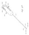
- FIG. 1Aillustrates one embodiment of the present invention in an exemplary use environment.
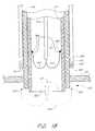
- FIG. 1Billustrates a cross-sectional view of the device in FIG. 1A in an exemplary use environment, such as a patient's thigh.
- FIG. 1Cillustrates another embodiment of the present invention in the exemplary use environment of FIG. 1 A.
- FIG. 1Dillustrates a cross-sectional view of the device in FIG. 1C in an exemplary use environment, such as a human thigh.
- FIG. 2is a partial cross-sectional view of the suturing device depicted in FIG. 1A having a suture catch assembly and a suture introducer housing.
- FIG. 3is a bifurcated perspective view of the suture introducer housing of FIG. 2 .
- FIG. 4is a partially schematic perspective view of the suture clasp arms of FIG. 2 .
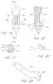
- FIG. 5is an elevational view of one configuration of a suture clasp arm.
- FIG. 6is an elevational view of another configuration of a suture clasp arm.
- FIG. 7is an enlarged elevational view of one configuration of a suture clasp.
- FIG. 8is an enlarged elevational view of a suture having bands crimped thereon.
- FIG. 9is an enlarged elevational view of another configuration of a suture clasp.
- FIG. 10is an elevational view of the suture clasp of FIG. 9 illustrating the action of a suture and the suture clasp as the suture is being removed from the suture clasp.
- FIG. 11Ais a cross-sectional top view of one configuration of a suture introducer housing, suture clasp arms, a suture, and a triangular spreader.
- FIG. 11Bis a cross-sectional side view of the suture introducer housing and triangular spreader of FIG. 11 A.
- FIGS. 12 and 13are partial cross-sectional views of another configuration of a spreader for deploying the suture clasp arms.
- FIG. 14is a partial cross-sectional view of an alternate configuration of the device for deploying the suture clasp arms.
- FIG. 15is a partial cross-sectional view of an alternate configuration of suture clasp arms.
- FIG. 16is a partial cross-sectional view of the device of FIG. 15 illustrating the suture clasp arms in a deployed position.
- FIG. 17is a bifurcated perspective view of the suture catch assembly of FIG. 2 .
- FIG. 18is a partial cross-sectional view of an alternate configuration of the suture catches and the suture clasp arms.
- FIG. 19is a schematic perspective view of a needle tip and one configuration of a suture catch.
- FIG. 20is a cross-sectional view of the suture catch of FIG. 19 taken along line 19 — 19 illustrating the position of a suture fitting captured by the suture catch.
- FIG. 21is a cross-sectional top view of the suture catch of FIG. 19 taken along line 20 — 20 .
- FIG. 22is a schematic illustration of another configuration of a suture fitting.
- FIG. 23is a side view of a suture clasp arm used to hold the suture fittings of FIG. 20 and 22.
- FIG. 24is a rear elevational view of a needle tip with an alternate configuration of the suture catch.
- FIG. 25is a cross-sectional view of the needle tip of FIG. 24 taken along line 24 — 24 of FIG. 24 .
- FIG. 26is a partial cross-sectional side view of an alternate configuration of a suture clasp arm to hold a suture fitting.
- FIG. 27is an end view of the suture clasp arm of FIG. 26 .
- FIG. 28is a perspective view of a three-sector arm actuator assembly with a catch in a distal position.
- FIG. 29is a perspective view of a button of the assembly of FIG. 28 .
- FIG. 30is a perspective view of a guide of the assembly of FIG. 28 .
- FIG. 31is a perspective view of the catch of the assembly of FIG. 28 .
- FIG. 32is a perspective view of the assembly of FIG. 28 with the catch in a proximal position.
- FIG. 33is a schematic partial cross-sectional view of the assembly of FIG. 28 with the catch in a distal position.
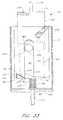
- FIG. 34is a partial cross-sectional view of the suture introducer housing of FIG. 2 with the introducer over the housing.
- FIG. 35is a partial cross-sectional view of the suture introducer housing of FIG. 2 with the suture clasp arms deployed.
- FIG. 36is a partial cross-sectional view of the suture introducer housing and suture catch assembly of FIG. 2 illustrating the operation of the suture catch assembly.
- FIG. 37is a partial cross-sectional view of the suture introducer housing and the suture catch assembly of FIG. 2 .
- FIG. 38is a schematic view of a vessel illustrating the location of the suture.
- FIG. 39is a schematic cross-sectional view of the vessel of FIG. 38 taken along line 40 — 40 .
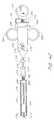
- FIG. 40is a partial schematic cross-sectional view of one configuration of the suturing device having a detachable arm deployment handle.
- FIG. 41is a cross-sectional view of the embodiment depicted in FIG. 1C with the distal end inserted through an arterial wall.
- FIG. 42is a cross-sectional view of the device of FIG. 41 with the suture clasp member partially deployed.
- FIG. 43Ais a perspective view of a suture clasp member, an actuator and a hollow elongated body of FIG. 41 .
- FIG. 43Bis an exploded view of the suture clasp member, pivot pin and actuator of FIG. 42 .
- FIG. 43Cis a perspective view of a two-piece suture clasp member.
- FIG. 43Dis a cross-sectional view of the two-piece suture clasp member of FIG. 43C and a spreader within the suture introducer head of FIG. 41 .
- FIG. 44is a perspective view of the suture introducer head and suture clasp member of FIG. 41 .
- FIG. 45is perspective view of the device of FIG. 44 with the suture clasp member partially deployed.
- FIG. 46is a rear perspective view of the device of FIG. 44 .
- FIG. 47is cross-sectional view of the device of FIG. 41 with the suture clasp member fully deployed.
- FIG. 48is a cross-sectional view of another embodiment of the present invention.
- FIG. 49is a cross-sectional view of one embodiment of a handle attached to the proximal end of the device of FIG. 41, the device of FIG. 48 or the device of FIG. 52 A.
- FIG. 50is a perspective view of the handle of FIG. 49 .
- FIG. 51is a cross-sectional view of another embodiment of a handle attached to the proximal end of the device of FIG. 41, the device of FIG. 48 or the device of FIG. 52 A.
- FIG. 52Ais a perspective view of the suture introducer head and the hollow elongated body of FIG. 41 with another embodiment of the suture clasp arms.
- FIG. 52Bis a cross-sectional view of the device of FIG. 52 A.
- FIGS. 53A-53Bare perspective views of one configuration of the suture clasp member of FIG. 52 A.
- FIG. 54is a perspective view of the device of FIG. 52A with the suture clasp member partially deployed.
- FIG. 55is a perspective view of the device of FIG. 52A with the suture clasp member fully deployed.
- FIG. 56is a perspective view of the device of FIG. 52A with the suture clasp member fully deployed and needles engaging the suture clasp member.
- FIG. 57is a perspective view of the handle of FIG. 49 .
- FIGS. 58-59are perspective views of a four-arm suture clasp member used with the device of FIG. 1C-1D.
- FIG. 60is an exploded view of another handle configuration attached to the proximal end of the device of FIG. 41, the device of FIG. 48 or the device of FIG. 52 A.
- FIG. 61is a perspective view of the handle of FIG. 60 .
- FIGS. 1A-1Billustrate one embodiment of the present invention in an exemplary use environment.
- the physicianmakes an initial incision 20 in the upper thigh 12 of a patient 2 .
- the physicianthen inserts a needle (not shown) into the incision 20 .
- the physicianknows the needle has pierced the femoral artery 16 .
- the physicianthen inserts a guidewire (not shown) through the needle and into the artery.
- the physicianmay take the needle out and insert a plastic needle (not shown) over the guidewire once the guidewire is in place.
- the guidewiremay then be taken out.
- CSIcatheter sheath introducer
- This introducer sheath 6is typically a single lumen catheter with a valve on its proximal end. The valve is used to prevent extraneous bleed back or to introduce medication into the patient's body.
- the vessel incision 26provides access for medical instruments and probes inside the arterial vessel 16 . Instruments may be inserted into artery 16 via the introducer sheath 6 to perform various procedures in the body.
- the suture assembly 4consists of the suture catch assembly 36 (described below), the suture introducer housing 24 , and the introducer sheath 6 .
- FIG. 1Billustrates a cross-sectional view of the device depicted in FIG. 1A in an exemplary use environment, such as a patient's thigh.
- the physicianwithdraws the CSI 6 and inserts the suture catch assembly 36 and the suture introducer housing 24 through the first incision 20 .
- the suture catch assembly 36 and suture introducer housing 24pass through the flesh 14 of the patient's thigh 12 and through the second incision 26 into the femoral artery 16 .
- the physicianmay first insert the suture introducer housing 24 , remove the CSI 6 , and then insert the suture catch assembly 36 .
- FIGS. 1C and 1Dillustrate another embodiment of the present invention in the exemplary use environment of FIG. 1 A. Unlike the device illustrated in FIGS. 1A-1B, the device illustrated in FIGS. 1C-1D does not require the removal of the CSI 6 in order for the device to deploy a suture.
- FIGS. 1A and 1Bwill now be described with reference to FIGS. 2-40. The device depicted in FIGS. 1C-1D will thereafter be described in further detail below with reference to FIGS. 41-50.
- FIGS. 1A-1B and 2 - 40Embodiments of FIGS. 1A-1B and 2 - 40
- FIG. 2shows one embodiment of the suturing device for suturing vessel walls and other biological tissue.
- the deviceis for use in suturing arterial vessel walls 22 .
- the devicecould be used to suture other tissue such as a patent ductus arteriosus, a patent foramen ovale, a heart defect, a puncture wound, and the like.
- the suturing devicecomprises a suture introducer housing 24 for insertion into an opening 26 in the arterial wall 22 .
- Suture clasp arms 28 , 30are deployably housed in the housing 24 during insertion. After insertion into the vessel 16 , the arms 28 , 30 are deployed to the position shown in FIG. 2 . When deployed, the suture clasp arms 28 , 30 extend outside the circumference of the suture introducer housing 24 . Each arm has at least one suture clasp 32 , schematically illustrated, for clasping a suture 40 .
- a penetrating mechanism, generally designated 34is provided for penetrating the vessel wall 22 . The penetrating mechanism 34 is provided on either the suture introducer housing 24 or on a suture catch assembly, generally designated 36 . When, as shown in FIG.
- the penetrating mechanism 34is part of the suture catch assembly 36 , the penetrating mechanism 34 also comprises suture catches 38 for catching the suture 40 and dislodging it from the suture clasps 32 .
- the suture catch assembly 36operates to pull the suture 40 held by the suture catches 38 through the vessel wall 22 . After the ends of the suture 40 are pulled outside the vessel wall 22 , the introducing housing 22 can be removed and the suture 40 tied to close the vessel opening 26 .
- FIG. 3shows one configuration where the suture introducer housing 24 is a generally cylindrical and thin walled hypo tube.
- the term “hypo tube”is used to describe a hollow elongated cylindrical member with a thin wall such that the inner diameter and outer diameter vary by a relatively small amount in the range of few thousandths of an inch to tens of thousandths of an inch.
- the outer surface 42 of the housing 24comprises a key way groove 44 (exaggerated for clarity) to align the housing 24 with a key 46 (FIG. 17) on the inner surface 48 of the suture catch assembly 36 .
- An arm actuation assembly 170for deploying the suture clasp arms 28 , 30 protrudes from the proximal end of the housing 24 , and an actuating wire or rod 50 extends from the actuation assembly 170 through the housing 24 to the suture clasp arms 28 , 30 .
- FIG. 2shows one configuration where the suture clasp arms 28 , 30 are attached to the distal end 54 of the actuating rod 50 .
- the arms 28 , 30are pivotally attached to the actuating rod 50 and pivot around pivot shaft 56 .
- the suture 40is held inside the housing 24 and is positioned underneath the spreader 102 , so that it can be removed from the entire housing 24 .
- the arms 28 , 30which are shown in more detail in FIG. 3, terminate with the suture clasps 32 (schematically illustrated).
- Each arm 28 , 30has an elongated body 58 which attaches to the pivot shaft 56 at one end and to the suture clasp 32 at the other. The length of the body 58 controls how far beyond the circumference of the suture introducer housing 24 the arms 28 , 30 extend when they are deployed by the actuating rod 50 .
- FIG. 5shows an alternate configuration of the arms 28 , 30 .
- the arms 28 , 30are Y-shaped with an offset body 64 , and there is a suture clasp at each tip 60 , 62 of the Y-shaped arm.
- the body 64is off center from the tips 66 , 68 , so that a complimentary arm can pivot on the same pivot shaft 56 without interference.
- the Y-shape of the armsallows them to pivot beside each other outwardly from and inwardly to their undeployed position without interference from the other arm.
- the Y-shape of the armalso provides an open area or suture catch receiving area 80 into which the suture catch 30 fits to catch the suture 40 .
- Other arm shapessuch as the h-shaped arm shown in FIG.
- the h-shaped armhas a body 70 with an aperture 71 for attachment to a pivot shaft 56 and each tip 72 , 74 of the arm is provided with a suture clasp.
- the body of the h-shaped armis positioned all the way to the side of the arm and functions similarly to the Y-shaped arm.
- the configuration of the suture clasp arm shown in FIG. 6also has a suture catch receiving area 80 A.
- FIGS. 7 and 8illustrate one configuration of the suture clasp 32 , which comprises a key hole shaped slot 76 which widens toward the end of the tip to receive the suture 40 .
- a loop 78is tied in each end of the suture 40 .
- the loop 78is sized to fit tightly between the suture clasps 32 on each arm 28 , 30 .
- the key hole shaped slot 76is elongated and narrows away from the end of the tip 60 to a neck 82 having a width W.
- the end 84 of the slot 76is circular with a diameter greater than the neck width W.
- the diameter of the circular end 84 of the slot 76is sized to receive either the outer diameter of a suture 40 , shown in FIG.
- the suture 40 or the bands 86have an outer diameter approximately the same size as the diameter of the end of the slot 76 but smaller than the neck width W. Because the diameter of the bands 86 (or suture 40 ) is smaller than the width of the neck 83 , the bands 86 snap into the end of the slot 76 and are securely held therein until removed by the suture catch 38 . In an alternate configuration (FIG. 14 ), it is desirable for the slots 76 to open upwardly when they are in the deployed position, so that the suture 40 is pulled straight up out of the slots 76 .
- FIG. 9shows another configuration of the suture clasps 32 .
- the arm 28 , 30comprises a shaft 88 extending to a plate or bar 90 .
- a resilient element 92such as a spring, is attached at each end of the bar 90 , and tips 94 are attached to the end of each resilient member 92 .
- the tips 94have slots as previously described and shown by FIG. 7 .
- the suture 40has beads 96 fixed thereto or knots tied therein. The beads are spaced apart by a distance just less than the distance between the outer edges 98 of the tips 94 . With this distance between the beads 96 , the tips 94 must be slightly bent toward each other thereby loading the resilient members 92 to receive the suture 40 .
- the tips 94are pulled inwardly and the resilient members 92 loaded, the suture 40 is held in place by the force from the resilient members 92 . Therefore, the suture 40 is held in tension between the tips 94 .
- the resilient members 92When the suture catch 38 is guided through the suture catch receiving area 100 , the resilient members 92 are further deformed as the suture 40 is forced to make an arc to receive the suture catch 38 as illustrated in FIG. 10 . The resilient members 92 then bend in the direction that the suture catch 38 is retracted, so that the suture 40 slides smoothly out of the clasp 32 . If desired, the outer edges 98 of the tips may be indented 99 to receive and more securely hold the beads 96 or knots on the suture 40 .
- FIG. 14illustrates an alternate configuration of the suture clasp slot.
- the slot 127opens upwardly toward the penetrating mechanism instead of transverse to the penetrating mechanism as in the previous configuration.
- FIG. 1Ais a cross-sectional top view of one configuration of the suture introducer housing 24 , the clasp arms 28 , 30 , the suture 40 , and a triangular spreader 102 .
- FIG. 11Ashows the triangular spreader 102 extending across a diameter line of the suture introducer housing 24 .
- the spreader 102may be shaped in alternative forms other than a triangle.
- FIG. 11Bis a side view of one configuration of the suture introducer housing 24 , the triangular spreader 102 and the direction of the clasp arms 28 , 30 as they extend downward into the blood vessel 16 .
- One vertex 104 of the triangular spreader 102is positioned centrally in the housing 24 and extends upwardly.
- the triangleis preferably isosceles with respect to the upward extending vertex 104 , so that the arms 28 , 30 spread uniformly when they engage the spreader 102 and pivot about the pivot shaft 56 .
- Each arm 28 , 30ultimately extends the same distance beyond the circumference of the housing 24 .
- the surfaces of the spreader 102 and arms 28 , 30 which engage to deploy the armsare preferably smooth, so that the deployment of the arms 28 , 30 is smooth.
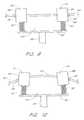
- FIGS. 12 and 13Another configuration for deploying the suture clasp arms is shown in FIGS. 12 and 13.
- the arms 106are pivotally attached to the actuating rod 50 with a pivot shaft 109 , and a circular spreader bar 108 or cam pin extending across a diameter line of the housing 110 .
- the actuating rod 50forces the suture clasp arms 106 to engage the circular spreader 108 , they are forced into the deployed position of FIG. 13 .
- the bottom surface 107 of the arms 106forms a curved camming surface for engaging the circular spreader 108 .
- the housing 110has two slit shaped openings 112 evenly spaced around the circumference of the housing 110 through which the arms 106 extend into the deployed position.
- the end of the openings 112also forms a stop 113 to prevent the arms 106 from moving past the deployed position.
- the shape of the arms 106is simplified. Because the arms 106 do not have to curve down out of the housing 110 , the arms 106 are straighter than in the previous configurations.
- Each clasp armcomprises an upper lever arm 114 pivotally attached at one end to the actuating rod 50 with a pivot shaft 116 and a lower pivot arm 118 pivotally attached to the other end of the upper lever arm 114 .
- the lower pivot arm 118rotates around a pivot shaft spreader 120 which is attached to the housing 122 and extends across a diameter line of the housing 122 .
- the upper lever arm 114rotates relative to the pivot shaft 116 , and the junction 124 between the upper and lower arms is translated downward (distally) and outwardly toward the circumference of the housing.
- the actuating rod 50is retracted from the housing, the junction is moved upward and centrally in the housing 122 , and the lower pivot arm 118 is rotated to the retracted position shown in partial dashed lines.
- the housing 122similar to the configuration of FIG. 13, has slit openings 126 .
- the openings 126extend a greater distance along the length of the housing 122 than in FIG. 13 to allow room for the lower pivot arm 118 to exit the housing 122 and provide sufficient room for the junction 124 to move outwardly.
- a stop 129 attached to the upper lever arm 114is placed between the upper lever arm 114 and the lower pivot arm 118 to prevent the arms from moving past the deployed position.
- the stop 129can be inherent in the lower pivot arm 118 and upper lever arm 114 . This would include a notch on the side of one of the arms which the other arm would contact to limit the movement of the arms.
- FIG. 14illustrates the use of a sealing member 52 inside the suture introducer housing 24 .
- the sealing member 52prevents blood flow back through the housing 122 .
- FIGS. 15 and 16Still another configuration of the clasp arm deployment mechanism is illustrated in FIGS. 15 and 16.
- a single resilient arm 128is attached to the actuating rod 50 .
- the resilient arm 128is predisposed in a deployed configuration shown in FIG. 16 .
- the prongs 130 of the arm 128are elastically deformed inwardly.
- the prongs 130expand to the predisposed deployed position.
- This configurationis easily adaptable to having four prongs 130 spaced at ninety degrees.
- any configuration and number of prongscan be incorporated into the device depending on the specific needs of the application.
- FIGS. 2 and 17illustrate a preferred configuration of the suture catch assembly 36 with a generally cylindrical outer tube 132 , which, as described above, includes a key 46 to mate with the key way groove 44 of the suture introducer housing 24 .
- the inner diameter of the tube 132is sized to fit over the outer diameter of the suture introducer housing 24 without any interference. This fit does not need to be tight because the suture catch assembly 36 is not inserted into the opening 26 of the vessel 16 . Therefore, there is no need to prevent the flow of blood between the suture housing 24 and the suture catch assembly 36 .
- the fit between the suture catch assembly 36 and the suture introducer housing 24does need to be close enough to assure that the suture catch 38 is properly aligned with respect to the suture clasps 32 . Proper alignment is accomplished by a close fit between the key 46 and the key way groove 44 .
- the catch assembly 36comprises a plurality of, preferably two, apertures 134 for slidably receiving respective needles 136 or other penetration members.
- the apertures 134extend through the length of the tube 132 and may be equally spaced around the circumference of the tube 132 in one configuration of the device.
- the blunt ends 138 of the needles 136are connected to an activation ring 140 , and springs 142 are interposed between the activation ring and the tube 132 .
- the springs 142hold the needles in a retracted position so that the needle points are within the tube 132 . With the needles 136 biased in a retracted position by the springs, the suture catch assembly 36 can be handled without the chance of inflicting an unintentional puncture wound.
- At least one stop 144is fixed on the inner surface 48 of the tube 132 and engages the top 146 of the suture housing 24 to fix the relative position between the suture housing 24 and the catch assembly 36 . Because the spring 142 can only be compressed a certain distance, the depth of entry of the needles 136 into the vessel 16 is controlled to prevent puncturing the opposite side of the vessel 16 . Furthermore, the fixed relative position between the suture housing 24 and catch assembly 36 assures that the needles 136 pass far enough into the suture catch receiving area 80 to catch the suture 40 .
- each needle 136Near the end of each needle 136 is the suture catch 38 .
- the suture catch 38is an aperture extending to the outer edge on one side of the needle 136 .
- the apertureis slot shaped and angled upwardly toward the proximal end of the device. While the needles are being pulled from the vessel 16 , the suture 40 is pulled to the bottom of the suture catch 38 where it cannot come loose.
- FIG. 18shows an alternate configuration of a penetrating mechanism, generally designated 150 , with the suture introducer housing 152 .
- the penetrating mechanismcomprises needle points 154 press fit onto arms 156 .
- the end of the arms 156 opposite the needle points 154are fixed to the actuating rod 50 .
- the arms 156are made of a resilient material exhibiting shape memory such as NITENOL, and the arms 156 are at rest in a deployed position shown in dashed lines. When the arms 156 are within the suture housing 152 , they are deformed to fit within the housing 152 .
- the arms 156return to their at-rest position with the needle points 154 beyond the circumference of the housing 152 .
- the suture 40is attached to the needle points 154 .
- the needle points 154are then pulled upward by the actuating rod 50 toward the vessel wall 22 , thereby penetrating the vessel wall 22 from within the vessel 16 .
- the suture catch 158has a V-shaped notch 160 with rounded tips 162 . There is a slit 164 extending up from the vertex of the notch 160 . The rounded tips 162 prevent the suture catch 158 from inadvertently puncturing the vessel wall 22 .
- the needle points 154fit into the notches 160 and cause the notches 160 to open farther along the slits 164 .
- the notch 160collapses to its original shape and traps the needle points 154 inside.
- the suture catch 158is then pulled proximally until the press fit between the needle points 154 and the arms 156 is overcome, and the needle points 154 are separated from the arms 156 .
- the actuation rod 50is then moved proximally to pull the arms 156 both into the housing 152 .
- an alignment mechanismcan be provided such as the key way described above. But in the configuration shown, the notch is circumferential. Thus, no alignment mechanism is needed, and any number of arms 156 extending from the actuating rod can be provided.
- the suture catch 158can be positioned over an introducer 168 if desired. If the proximal end of the introducer 168 is too large for the suture catch 158 to fit over, the suture catch 158 could be made of a flexible material with a longitudinal slit over its entire length allowing it to be expanded to fit around the diameter of the introducer 168 . The arms 156 would be modified so that the needle points 154 extend beyond the circumference of the introducer 168 .
- FIGS. 19 through 23illustrate an alternate configuration of the suture catch and suture clasp.
- a needle 400is provided with a slotted opening 402 having a peg 404 extending from the top of the opening 402 through a portion thereof.
- the peg 404has a narrow and rounded front peg surface 406 with an identical radial location on the needle 400 as the outer surface of the needle 400 .
- the back peg surface 408 of the needle 400is relatively wide, rounded, and located toward the radial center of the needle 400 .
- the peg sides 410are flat and angled relative to the walls 412 of the slotted opening 402 .
- the slotted opening 402receives suture fitting 414 having a shaft 416 connected, preferably by crimping, to the suture 40 and an enlarged termination 418 which is preferably spherical.
- the alternate suture fitting 420 of FIG. 22has a half spherical termination 422 with rounded edges.
- the half spherical termination 422does not protrude beyond the diameter of the needle 400 .
- This half spherical termination 422reduces the trauma to the vessel wall 22 when the needle 400 is retracted.
- the shaft in either configurationhas a length short enough not to protrude from the diameter of the needle 400 when the suture fitting is held by the needle 400 . This also reduces trauma to the vessel wall 22 during retraction.
- the suture fitting 414is held by a modified suture clasp arm 424 having an aperture 426 to receive the shaft 416 of the suture fitting 414 .
- the wall 428 of the apertureis slowly tapered so that the diameter decreases as the aperture 426 moves inwardly in the arm 424 .
- This frustoconical shapeprovides a secure press fit with the suture fitting shaft 416 .
- Other aperture shapesare possible so long as the press fit is secure and is of a force which can be overcome by the retraction of the arm 424 .
- the shaft 416 of the suture fittingscan also be tapered to better mate with the aperture 426 .
- the termination 418 , 422engages the peg 404 forcing it to one side allowing the termination 418 , 422 to slide against the peg 404 until the termination 418 , 422 is past the peg 404 .
- the peg 404snaps toward its at rest central position thereby capturing the termination 418 , 422 and hence the suture 40 .
- the suture clasp arm 424is retracted, the press fit is overcome and the suture fitting 414 is pulled from the arm 424 .
- the peg 404snaps back into its central position, it tends to pull the suture fitting 414 away from the suture clasp arm 424 . This can be utilized to help overcome the press fit. With the suture filling securely held, the needles are retracted, the suture fittings 414 cut from the suture 40 , and the suture 40 tied.
- FIGS. 24 and 25illustrate another configuration of the suture catch.
- a needle 450is provided with a slot shaped opening 451 with a U-shaped raised portion 452 in the lower front of the slot 451 .
- the opening 451also defines a suture fitting receiving area 454 at the top of the opening 451 for receiving a suture fitting 456 and a suture fitting catch area 458 in the lower back of the slot adjoining the raised portion 452 .
- the suture fitting 456has a spherical tip 459 , and an arcuate neck 460 which tapers down to a cylindrical shaft 462 .
- the spherical tip 459is sized to fit through the suture fitting receiving area 454 but not through the U-shaped raised potion 452 .
- the raised portion 452holds the suture fitting 456 in the suture fitting catch area 458 .
- the raised portion 452angles toward the back of the needle 450 , so that it becomes larger as it extends farther down the needle 450 .
- FIGS. 26 and 27show another configuration of the suture clasp arms 464 , which comprises an upwardly facing key hole shaped opening 466 for holding the suture fitting 456 .
- the opening 466faces upwardly, that is in the direction of needle retraction, to aid in the removal of the suture fitting 456 from the suture clasp arm 464 .
- the suture catchis activated to penetrate the tissue to be sutured.
- the suture clasp arms 464are deployed directing the suture fitting 456 into the suture fitting receiving area 454 .
- the neck 460 of the suture fitting 456is engaged by the raised portion 452 , and the angled surface of the raised portion 452 pulls the suture fitting 456 farther and farther toward the back of the needle.
- the suture fitting 456is being pulled out of the suture clasp arm 464 as the needle 450 is retracted. If the suture fitting 456 is not completely removed from the suture clasp arm 464 when it contacts the bottom of the opening 451 , it is snapped upwardly pass a neck 468 of the key hole opening 466 and out of the suture clasp arm 464 .
- the control of the distal and proximal translation of the actuating rod 50is preferably performed by the three sector, arm actuator assembly, generally designated 170 , which is attached to the suture introducer housing 24 (see FIG. 3 ).
- Each sector of the arm actuator assembly 170is substantially identical.
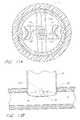
- FIGS. 28-31show that the arm actuator handle is comprised of three pieces: a button 172 , a cylindrical guide 174 , and a catch 176 .
- the button 172comprises an actuation post 178 extending centrally from a closed end of a cylindrical body 180 .
- the cylindrical body 180is sized to longitudinally slide in the guide 174 .
- Three button tabs 182are spaced equally around the outer surface of the cylindrical body at the end opposite the actuation post 178 . Thus, there is one button tab 182 in each sector.
- the catch 176comprises three catch tabs 184 corresponding to the three button tabs 182 , a cylindrical body 186 which is sized to fit rotatably inside the cylindrical body 180 of the button 172 , and a control ring 188 at an end of the cylindrical body 186 for engaging the three button tabs 182 .
- the control ring 188is at the end of the catch 176 corresponding to the end of the button 172 having the button tabs 182 , and the catch tabs 184 which rotate from sector to sector extend radially from the central ring 188 .
- the guide 174which is attached at its proximal end to the housing, has three channels 190 and three notches 192 , and the guide 174 is open at both ends; so that the button 172 protrudes from the proximal end, and the catch 176 can extend from the opposite (distal) end.
- the button tabs 182 and the catch tabs 184are slidable within the channels 190 , each button tab 182 stays in the same channel 190 while each catch tabs 184 is rotated from a channel 190 to a notch 192 and to another channel 190 during operation.
- the outer diameter of the button 172is sized to slide inside the guide 174 .
- the diameter of the control ring 188is sized to rotate freely within the guide 174 with minimum clearance, and the catch cylindrical body 186 is sized to rotate and slide longitudinally inside the button cylindrical body 180 with minimum clearance. This leaves a relatively large catch gap 196 between the catch cylindrical body 186 and the guide 174 . Therefore, the length of the catch cylindrical body 186 is preferably long enough so that it is never withdrawn from the button cylindrical body 180 during operation.
- the button tabs 182have a thickness sufficient to extend across the gap 194 and into the channels 190 .
- the button tabs 182also overlap the diameter of the control ring 188 , so that the button tabs 182 can engage the control ring 188 .
- the bottom surface 195 of the button 172is contoured to mate with the control ring 188 .
- the catch tabs 184have a diameter and thickness so that they slide in the channels 190 and fit into the notches 192 .
- the outer diameter of the guide 174is the largest diameter thereby assuring adequate clearance for translation of the button 172 and catch tabs 184 .
- the catch 176starts out in a proximal position with the catch tabs 184 in the channels 190 as shown in FIG. 32.
- a rotation spring 198is held in compression between fixed plate 200 , which is attached to the housing 24 , and the catch 176 .
- the rotation spring 198biases the catch 176 in the proximal direction, which corresponds to a retracted suture clasp arm position.
- the catch 176rotates in the direction of arrow 202 in FIG. 32 .
- the rotationis created by the rotation spring 198 pushing a top angled surface 204 of the catch tab 184 against the bottom angled surface 206 of the button tabs 182 .
- the physicianagain depresses the actuating post 178 , so that the button tabs 182 engage the V-shaped depressions 212 in the control ring 188 located between the catch tabs 184 .
- Thispushes the catch tabs 184 below the bottom of the guide 174 .
- the rotation spring 198 pushing upward on the guide 174causes the slide surface 214 of the V-shaped depression 212 to slide across the bottom surface of the button tab 182 causing the catch tabs 184 to rotate and move upwardly until they engage the angled bottom return surfaces 216 of the guide 174 .
- a button spring 218can be provided between the catch 176 and the button 172 to return the button 172 to an upward position after it is released. If the button spring 218 is used, the button tabs 182 contact the tops of the channels 190 preventing the button 172 from coming off the assembly.
- the suture clasp arms 28 , 30are completely deployed when the catch tab 184 is in the notch 192 against the notch stop 210 .
- the catch tab 184is pushed below this level several times.
- a resilient member 220is placed in the actuating rod 50 .
- the resilient member 220is compressed allowing the catch tab 184 to be moved the rest of the way below the bottom surface of the guide so that it can rotate to the next position. This prevents damage to the spreader 102 , bending the actuating rod 50 , and risk of injury to the vessel 16 .
- the vertex 222 of the button tab 182is not aligned with the bottom of the V-shaped depression 212 when the V-shaped depression 212 is aligned with the channel 190 .
- the vertex of the depressions 212is positioned to a side of the vertex of the button tab 182 in the rotational direction, so that the catch 176 is allowed to rotate until it is underneath the shallow end of the return surface 216 of the guide 174 .
- the catch tab 184when the catch tab 184 is inside the channel 190 , the angled surfaces 224 of the control ring 188 corresponding to the catch tab 184 continue past the catch tabs 184 to again allow initial rotation of the catch 176 until the catch tab 184 is beneath the shallow end of the notch surface.
- the catch tab 184can rotate underneath the shallow end of the notch 192 before the button tabs 182 contact the lowest point of the control ring surfaces 224 and rotation is restricted.
- the actuation post 178is released raising the button tab 182 out of the way, and the catch 176 can complete its rotation.
- FIGS. 1, 2 and 34 through 36The operation of the device is illustrated in sequence by FIGS. 1, 2 and 34 through 36 .
- the introducer sheath 6is left in place, and the suture introducer housing 24 is inserted into the introducer 6 and introduced into the artery 16 as shown in FIGS. 1A and 1B.
- the actuation post 178is then depressed, as illustrated by arrow 240 in FIG. 35 to deploy the suture clasp arms 28 , 30 outwardly as illustrated by arrows 242 so that portions, preferably the ends, are positioned on opposite sides of the opening 26 with the suture 40 extending transverse to the flow of blood.
- the introducer 6is then removed, leaving the suture introducer housing 24 with the suture clasp arms 28 , 30 deployed inside the artery 16 .
- the opening 26 in the vessel 16closes around the housing 24 after the introducer 6 is removed.
- the suture introducer housing 24is then oriented so that the arms 28 , 30 extend transversely to the flow of blood through the vessel 16 which is illustrated by arrow 244 .
- the suture catch assembly 36is then inserted over the housing 24 and the stop 144 is brought into contact with the top 146 of the housing 24 as shown in FIG. 2.
- a physiciandepresses the activation ring 140 as illustrated by arrows 246 (FIG. 36) pushing the needles 136 through the vessel wall 22 and puncturing holes 248 in the vessel wall 22 .
- the suture catch 38catches the suture 40 , and the suture catch assembly 36 is pulled proximally as illustrated by arrows 250 (FIG. 37 ).
- the needles 136can be retracted inside the suture catch assembly 36 or left deployed.
- the suture 40is cut from the suture catch 38 and pulled tight to remove it from the housing 24 .
- the suture clasp arms 28 , 30are retracted by depressing the actuation post 178 again, and the suture 40 is pulled tight simultaneously with the housing 24 being pulled out of the artery 16 .
- the length of the actuation post 178is set to correspond with the height of the depressed activation ring 140 .
- the actuation post 178is simultaneously depressed for the second time thereby retracting the arms 28 , 30 simultaneously with pulling the suture catch assembly 36 proximally.
- the pattern of holes shown in FIGS. 38 and 39is left.
- the suture 40closes the artery vessel opening 26 transverse to the flow of blood. This is the most efficient direction to close the opening 26 .
- additional suture clasp armsit is preferred that they make additional holes around the circumference of the opening as shown in dashed lines in FIG. 38, so that sutures again pull the opening 26 closed in a direction transverse to the flow of blood.
- the present inventioncould be similarly used to close a patent ductus arteriosus, a patent foramen ovale, a heart defect, a puncture wound in the skin, and other tissues requiring suturing.
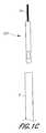
- FIG. 40An alternate configuration of the suturing device is shown in FIG. 40 .
- the devicecomprises a pair of suture clasp arms 270 attached to the end of an actuating rod 272 in accordance with one of the above described configurations.
- the actuating rodextends through a needle cover 274 and slidably through a needle actuator 276 to a suture arm deployment handle 278 .
- the actuating rod 272Near the deployment handle 278 the actuating rod 272 has, a severable junction 279 .
- the junction 279is threaded or snap fit allowing the actuating rod 272 to be quickly separated and joined thereby quickly removing or attaching the handle 278 from the remainder of the device.
- the actuating rod 272can, in the alternative, have a junction where it enters the needle cover 274 .
- Needles 280are held near their distal ends by a needle guide 282 and pass through a stop 284 that limits the deployment distance of the needles 280 .
- the needles 280fixably attaching to the needle actuator 276 .
- a spring 286is interposed between the stop 284 and the needle actuator 276 to bias the needles 280 in a retracted position.
- a second stop 288is fixed to the actuating rod 272 on the opposite side of the needle actuator 276 to prevent the needles 280 from being pulled out of the needle guide 282 .
- the actuating rod 272terminates at a thumb ring 290 separated from the distal end of the suture arm deployment handle 278 by a thumb ring spring 292 which biases the thumb ring 290 in a proximal position which corresponds to a retracted position of the suture clasp 270 .
- the handle 278also comprises two finger rings 294 , 296 on opposite sides of the handle allowing a physician to smoothly overcome the force of the thumb ring spring 292 .
- the distal portion of the deviceis inserted into the introducer 6 with the handle 278 detached.
- the introducer 6is removed and the handle 278 is attached to the device by connecting the actuating rod 272 .
- the thumb ring 290is pushed distally to deploy the suture clasp arms 270 .
- a clip 298hooks onto a clip ring 300 to lock the suture clasp arms 270 in the deployed position.
- the actuating rod 272includes a resilient member 302 (shown schematically), which functions, as described in the previous configurations, to prevent the suture clasp arms 270 from moving past their deployed position.
- the resilient member 302can simply comprise a spring, or a spring housing can be provided on one part of the actuation rod 272 to receive a spring and a slidable plunger therein.
- the plungerwhich is provided on the opposite part, slides to a maximum distal position defined by the spring housing and is biased in that position by the spring.
- the plungerWhen the suture clasp arms 270 reach a deployed position, the plunger is then forced into the spring housing, compressing the spring and allowing the upper portion of the actuation rod 272 to travel distally without forcing the suture clasp arms 270 past a deployed position or bending the actuation rod 272 .
- a thumb ring stop 304prevents the thumb ring 290 from being pushed beyond a point for which the resilient member 302 could compensate.
- the physiciangrasps the needle actuator 276 , which has a central curved indented surface 306 to make it easy to grasp, and pushes the needle actuator 276 distally.
- the needles 280are pushed into the vessel 16 and catch the suture 40 as described in one of the above configurations.
- the stop 284prevents the needles 280 from penetrating too far and damaging the vessel 16 .
- the spring 286pushes the needles 280 back to a retracted position when the needle actuator 276 is released.
- the thumb ring 290is pushed in a direction transverse to the length of the actuating rod and away from the clip 298 as illustrated by arrow 308 to release the clip 298 and retract the suture clasp arms 270 .
- the entire deviceis retracted, the suture 40 cut from the needles 280 , and the suture 40 tied to close the opening 26 .
- the handle 278is detachable, the handle 278 could be used in conjunction with the above described configurations. In such a case, the arm actuator assembly would be removed, and the actuating rod 50 would extend through the top of the housing 24 . The end of the actuating rod 50 would be modified to connect to the handle 278 .
- FIGS. 1C-1D and 41 - 50Embodiments of FIGS. 1C-1D and 41 - 50
- the suture introducer housing 24 and the suture catch assembly 36consist of two separate pieces, wherein the suture catch assembly 36 operatively fits around the suture introducer housing 24 .
- the physicianfully removes the original CSI 6 before inserting the suture catch assembly 36 to penetrate the blood vessel wall and catch the ends of a suture.
- the removal of the CSI 6 and the introduction of the suture catch assembly 36may disturb the flesh 14 or enlarge the incision 20 and add to the complexity of the procedure.
- FIGS. 1C-1D and 41 - 50do not require the full removal of the original CSI 6 (used for the original percutaneous approach procedure, such as an angioplasty/angiography procedure) in order for the device to catch the ends of a suture. Rather, as depicted in FIG. 41, the distal portion of the device 520 passes through the CSI 6 and the flesh 14 of the patient's thigh 12 with minimal disturbance to the flesh 14 , and through the second incision 26 into the femoral artery 16 .
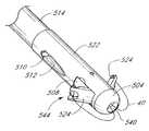
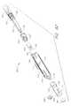
- FIGS. 41-48illustrate the device 520 depicted in FIGS. 1C-1D where the suture introducer housing and the suture catch assembly are integrated into a single suture insertion and retraction device 520 .
- This suturing device 520may comprise a one-piece suture insertion and retraction housing 515 as shown in FIG. 48, or may comprise a suture introducer head 522 attached to the distal end of a hollow elongated body 514 as shown in FIG. 41 .
- the suture introducer head 522 and the hollow body 514are narrower in diameter than the configurations illustrated in FIGS. 1A-1B and 2 - 40 because the suture clasp member 500 and the needles 546 reside in the same longitudinal space.
- the needles 546share the same housing as the suture clasp member 500 (while they are all in their retracted state), but are higher up (proximally) in the suturing device 520 than the suture clasp member 500 .
- An important feature of this embodimentis that it uses flexible needles 546 which bend outward, away from the axis of the device 520 , when in the extended position (as shown in FIG. 47 ).
- the dimensions of the suturing device 520may vary according to the suture site and the biological tissue intended to be sutured.
- the diameter of the suture head introducer 522is about 0.105 inches
- the diameter of the hollow elongated body 514is about 0.098 inches.
- the suture introducer head 522has two needle ports or apertures 510 formed therein (one per needle 546 ) proximal to the suture clasp arms 524 .
- Each needle portincludes a needle guiding portion 512 (“needle guide”), in the form of an outwardly curved groove or channel, which guides the corresponding needle 546 along a particular path.
- the needle guides 512may be formed within the suture introducer head 522 (as shown in FIG. 41) as part of a mold, or may be separate pieces (not shown) that are inserted into the suture introducer head 522 during manufacture.
- FIGS. 41-48Another advantage of the embodiments illustrated in FIGS. 41-48 is the required size of the initial incision 20 into the patient's body and the diameter of the introducer sheath 6 used to insert the device 520 may be reduced.
- the size of the suture device 520may vary depending on the application and the size of the vessel incision 26 .
- FIG. 46shows a preferred configuration of the hollow elongated body 514 with five lumens.
- Two of the lumens 516are used to house the needles 546 (FIG. 41 ).
- Another lumen 530is used to house the actuating rod 50 .
- Another lumen 532is used to hold the length of the suture 40 to prevent the suture 40 from becoming tangled.
- the suture 40may be stored in the actuating rod lumen or in a hole drilled into the suture clasp arm 500 .
- the fifth lumen 534is preferably used for ‘bleed back,’ which lets the physician determine whether the distal end 504 of the suture introducer head 522 is still positioned in the artery 16 after the physician removes the catheter sheath introducer (CSI) 6 .
- Bleed backis accomplished by the hole 540 (FIG. 45) at the distal end 504 of the suture introducer head 522 , the suture clasp arm apertures 508 and any other openings in the suture introducer head 522 .
- the direction of blood flow for bleed backis shown by the dashed arrows in FIGS. 41 and 48.
- the bleed back lumen 534extends to a port (not shown) at a proximal portion of the device, and the physician can observe the blood pressure through bleed back lumen 534 by monitoring blood flow from the port.
- the bleed back lumenmay be attached to a balloon which inflates when the distal portion 504 of the suture introducer head 522 is within the blood vessel 16 .
- a pressure sensoris associated with the blood flow lumen 534 to provide the physician with a numeric reading.
- the fifth lumen 534may be used to inject medication or for diagnostic purposes.
- two thin stripes 538are marked on the exterior of the elongated body 514 which denote the circumferential location of the two needles 546 . These stripes extend along a portion of the elongated body 514 which is outside the patient's body. These stripes help the physician to align the needles 546 with the axis of the blood vessel 16 , so that the needle incisions 248 (FIG. 47) will be longitudinally aligned. As described above for FIG. 38, the suture 40 closes the artery vessel opening 26 transverse to the flow of blood. This is the most efficient direction to close the opening 26 . Proper insertion of the needles 546 reduces the risk of damage to the vessel walls 22 , 506 . Alternatively, there may be only one stripe to denote the circumferential location of one of the two needles 546 . The physician will know the circumferential location of the other needle 546 because the needles 546 are 180 degrees apart.
- the exterior surface of the elongated body 514includes a marker 539 which denotes the proximal position to which the CSI 6 should be partially withdrawn (after the distal portion of the suturing device 520 has been inserted into the blood vessel 16 ) to expose the needle apertures 510 .
- the partial withdrawal of the CSI 6is described below.
- the marker 539is shown as a visual marker, but may additionally or alternatively be in the form of a ridge, groove, or other physical structure which interacts with a corresponding structure of the CSI to allow the physician to position the CSI using the sense of feel.
- the CSI 6 and elongated body 514could be configured to releasably engage or interlock with one another when the CSI reaches the proper position along the body 514 .
- a specially formed CSIwhich includes such an interlocking structure is included within the scope of the invention.
- One or more additional longitudinal markerscould be provided along the body 514 , distal to marker 539 , to indicate other relative positions of the CSI and the body 514 , such as the position at which the retractable arms 524 are exposed outside the CSI.
- the device 520includes a single, resilient suture clasp member 500 attached to the actuating rod 50 .
- This resilient suture clasp member 500is preferably of a unitary construction as shown.
- the suture clasp member 500comprises a center or hinge portion 542 and two suture clasp arms 524 (one for each needle 546 ).
- Each suture clasp arm 524has a suture clasp 544 at the end thereof.
- the hinge portion 542 of the suture clasp member 500acts as a “living hinge” because it has a memory which causes the member 500 to return to a partially open, unretracted position (FIG. 42) when a force (applied via rod 50 ) is released.
- FIGS. 41 and 42the suture clasp member 500 is deployed in the artery 16 in its predisposed (relaxed or natural) position.
- FIG. 41the suture clasp member 500 is retracted into the suture introducer head 522 in its compressed (stressed or tensed) position.
- the arms 524are moved to the retracted position by applying a distal force to the actuator rod 50 , which causes the arms to contact deflection surfaces 518 (FIG. 42 ).
- This suture clasp member 500is preferably composed of a resilient shape memory material such as NITENOL.
- the suture clasp member 500may alternatively be composed of another material with spring-like characteristics, such as plastic, spring steel, stainless steel or any variations thereof. Further, the suture clasp member 500 could be composed of two arms that are hingedly connected to the actuating rod 50 without the use of a resilient hinge, as shown in FIGS. 43C and 43D and described below.
- the living hinge configurationis easily adaptable to having three arms spaced at 120 degrees or four arms (as in FIGS. 58 and 59) spaced at ninety degrees. If there are three arms, then there are preferably 3 needles 546 and six lumens in the elongated body 514 . Thus, other configurations and numbers of arms can be incorporated into the device to accomplish the specific needs of the application.
- the needles 546are flexible and preferably made from a material with shape memory, such as SUPERFLEX NITENOL. Alternatively, the needles 546 may be composed of spring steel, surgical stainless steel or any variation thereof. The diameter of the needles 546 is preferably about 0.019 inches, but needles with other diameters may be used in accordance with the present invention.
- the needle insertion guidescause the needles 546 to bend radially outward.
- the needles 546also preferably further bend slightly (radially outward) when they come in contact with the angled surfaces 545 of the suture clasp arms 524 , as shown in FIG. 47 .
- the needles 546are retracted into the needle lumens 516 , they resume a straight configuration as a result of their resiliency.
- FIGS. 41-48preferably uses flexible needles which bend during deployment, it is contemplated that non-bending needled, which may be either straight or curved, could alternatively be used.
- the actuating rod 50attaches to the resilient suture clasp member 500 by a pivot pin 502 .
- the actuating rod 50 in this configurationpreferably comprises a single shaft (as shown), but may comprise a plurality of shafts in other configurations.
- FIG. 43Cis a perspective view of a non-living hinge embodiment or a two-piece suture clasp member 501 .
- FIG. 43Dis a cross-sectional view of the two-piece suture clasp member 501 and a ramp or spreader 523 within the suture introducer head 522 .
- the hinge portion of the suture clasp arms 525 , 525 ′ with suture clasps 544may be similar to a hinge portion shown in FIG. 53, which is described below.
- the spreader 523may be a separate piece attached within the suture introducer head 522 .
- the spreader and suture introducer head 522may comprise a single molded piece.
- the length of the suture clasp arm 525is preferably about 0.174 inches.
- the length of both of the suture clasp arms 525 , 525 ′ together in their fully extended position (deployed with both arms parallel to each other)is preferably about 0.288 inches. In other configurations of the suture clasp arms 525 , 525 ′, the dimensions may vary.
- the actuating rod 50is advanced distally, and the interior edges 518 of introducer head 522 come in contact with the suture clasp arms 525 , 525 .′ The interior edges 518 of introducer head 522 cause the two suture clasp arms 525 , 525 ′ to retract radially inward relative to the actuating rod 50 .
- the general use and operation of the two-piece suture clasp member 501is similar to the use and operation of the suture clasp member 500 shown in FIG. 43A, as described below.
- the proximal portion of the suturing device 520preferably includes a handle which allows the physician to externally operate the suture clasp arms 524 and the needles 546 inside the blood vessel 16 .
- This handlepreferably has three actions: a first action in which the actuating rod 50 applies a proximal force to the hinge portion 542 to deploy and maintain the arms 524 in a fully outward position (FIG. 47 ); a second action to advance the needles 546 distally (FIG. 47) and pull the needles 546 back proximally using one or more springs; and a third action in which the actuating rod 50 applies a distal force to the hinge portion 542 to retract the arms 524 (FIG. 41 or 48 ).
- the handlemay be a 2-action handle in which one of the two actions is a combination of two of the three actions described above for the 3-action handle.
- the actuating rod 50applies a proximal force to the hinge portion 542 to deploy and maintain the suture clasp arms 524 in a fully extended state of FIG. 47 .
- the needles 546automatically advance distally (FIG. 47) and retract proximally to capture the looped ends of the suture 40 .
- the actuating rod 50applies a distal force to the hinge portion 542 to retract the arms 524 (FIG. 41 or 48 ).
- This 2-action handleis suited for physicians with more experience in operating this suture device 520 . It will be apparent to one of ordinary skill in the art that a 1-action handle or a 4-action handle (inserting and withdrawing the needles 546 as two separate actions) could be used, or that separate handles or triggers could be provided for different actions.
- FIG. 49is a cross-sectional view of one embodiment of a handle 550 operatively attached to the proximal end of the hollow elongated body 514 of FIG. 41 or the single suture insertion and retraction housing 515 of FIG. 48 or the device of FIG. 52 A.
- FIG. 50is a perspective view of the handle 550 .
- FIG. 57is a perspective view of the handle 550 of FIG. 49 .
- the handle 550comprises an actuating rod aperture 551 , a main housing 552 , a pair of finger grips 554 , a suture clasp arm piston 556 with a locking groove 576 , a needle piston 560 with at least one raised key portion 562 , a releasor 568 with a locking stopper 572 , a pivot pin 570 , a releasor support 574 , a compression spring (not shown) operatively positioned in a spring recess 578 between the suture clasp arm piston 556 and the needle piston 560 , a needle piston support cylinder 580 with at least one grooved recess 564 and needle clamps 584 .
- the housing 552is attached to or is a continuation of the hollow elongated body 514 of FIG. 41 or the single suture insertion and retraction housing 515 of FIG. 48 .
- the housing 552is separate from the hollow elongated body 514 or single suture insertion and retraction housing 515 .
- the actuating rod 50connects the housing 552 with the hollow elongated body 514 or single suture insertion and retraction housing 515 .
- a proximal portion of the actuating rod 50slides through the actuating rod aperture 551 at the distal end of the housing 552 .
- the proximal end of the actuating rod 50is attached to the distal end 558 of the suture clasp arm piston 556 , which is slidably received within the main housing 552 .
- a compression spring(not shown) resides in the spring recess 578 of the housing 552 between the suture clasp arm piston 556 and the needle piston 560 and simultaneously exerts two forces: a distal force on the suture clasp arm piston 556 ; and a proximal force on the needle piston 560 .
- the needle clamps 584 of the needle piston 560hold the proximal ends of the needles 546 .
- the needle piston 560is slidably received within a distal portion of the housing 552 .
- the needle piston support cylinder 580is attached to the housing 552 and preferably does not move relative to the housing 552 .
- the releasor 568pivots radially inward and outward on the pivot pin 570 .
- the releasor support 574exerts a radially outward force on the releasor 568 . This force causes the releasor 568 to pivot and the locking stopper 572 to fall into the locking groove 576 of the suture clasp arm piston 556 when the locking groove 576 is aligned to receive the locking stopper 572 .
- the releasor support 574is preferably made of a resilient shape memory material such as NITENOL.
- the releasor support 574may alternatively be composed of another material with spring-like characteristics, such as plastic, spring steel, stainless steel or variations thereof. Other embodiments of the handle are described below with reference to FIGS. 57, 60 and 61 .
- the physicianinserts the suture introducer head 522 through a catheter sheath introducer (CSI) 6 and into the artery 16 (FIGS. 1 C- 1 D).
- the CSI 6is then partially withdrawn along the body 514 of the suturing device 520 to remove the CSI 6 from the artery 16 and expose the needle apertures 510 , as shown in FIG. 41 .
- the distal end 504 of the introducer head 522has a smooth, rounded surface to prevent injury to the opposite vessel wall 506 when inserting the introducer head 522 .
- the blood flow in the artery 16is uninterrupted because the introducer head 522 does not occlude the artery 16 .
- the physicianmay use the aperture 540 at the distal end of the suture introducer head 522 and the bleed back lumen 534 to determine when the distal end 504 of the suture introducer head 522 is in the artery 16 .
- the actuating rod 50holds the resilient suture clasp member 500 in its compressed position within the introducer head 522 .
- the actuating rod 50applies a downward force while the interior edges 518 of the introducer head 522 apply an inward force on the two suture clasp arms 524 .
- the combination of these two forcescause the hinge portion 542 of suture clasp member 500 between the two arms 524 to elastically deform or compress.
- the suture clasps 544hold the looped ends of a suture 40 in the angled slot of the suture clasps 544 as shown in FIGS. 41-43A.
- the looped ends of the suture 40are held securely by the suture clasps but are positioned for easy removal by the suture catches 38 of the needles 546 .
- the physicianmay deploy the suture clasp arms 524 (FIGS. 42) by pulling the finger grips 554 in a proximal direction relative to the housing 552 (FIG. 50 ).
- a physicianmay pull the suture clasp arm piston 556 proximally by placing the physician's index and middle finger around the finger grips 554 and pushing on the proximal end 582 of the housing 552 . This action is similar to operating a standard syringe. This motion compresses the spring (not shown) in the spring recess 578 of the handle 550 in a proximal direction.
- the actuating rod 50moves in a proximal direction relative to the elongated body 514 or housing 515 . This is shown by the arrows in FIG. 42 .
- This motioncauses the suture clasp member 500 to deploy or open to its predisposed or natural position as shown in FIG. 42 .
- the suture clasp arms 524deploy out of the introducer head 522 into the blood vessel 16 through two suture clasp arm apertures 508 (FIG. 42 ), one on either side of the introducer head 522 .
- the locking stopper 572 at the distal end of the releasor 568moves radially inward and falls into the locking groove 576 of the piston 556 .
- the locking stopper 572in combination with the locking groove 576 , prevents the suture clasp arm piston 556 from advancing distally.
- the force of the spring in recess 578prevents the suture clasp arm piston 556 from moving proximally.
- the locking of the suture clasp arm piston 556stabilizes the suture clasp arms 524 in a locked position before the needles 546 are advanced distally.
- the suture clasp arms 524preferably have reached their fully extended position, as shown in FIG. 47 .
- the actuating rod 50(attached to the suture clasp arm piston 556 ) has pulled the resilient suture clasp member 500 up, and the proximal inside edges 536 of the aperture 508 have come in contact with the arms 524 of the suture clasp member 500 .
- FIG. 47The pulling of the actuating rod 50 and the stationary inside edges 536 of the apertures 508 cause the arms 524 to bend backward until the arms 524 are longitudinally aligned with each other, as shown in FIG. 47 .
- the resilient suture clasp member 500is deformed from its natural configuration again, but this time in an extended position instead of a compressed position.
- the physicianmay move the suturing device 520 proximally so that the arms 524 touch the interior of the vessel wall 22 while the needles 546 advance distally and capture the ends of the suture 40 from the suture clasps 544 .
- the physiciantwists the needle piston 560 clockwise or counter-clockwise until the raised key portion 562 of the needle piston 560 matches the grooved recess 564 of the needle piston support cylinder 580 .
- the grooved recess 564 of the needle piston support cylinder 580allows the raised key portion 562 of the needle piston 560 to advance distally. Otherwise, the needle piston 560 may not be advanced distally if the raised key portion 562 does not match the grooved access 564 .
- the needle piston support cylinder 580 and the raised key portion 562 of the needle piston 560prevent the needles 546 from advancing distally prematurely or improperly. Premature or improper insertion of the needles may cause damage to the patient's surrounding tissue 14 (FIGS. 1B and 1D) or the blood vessel 16 .
- the physicianmay advance the proximal end of the needle piston 560 (with the physician's thumb or palm) in a distal direction relative to the proximal end 582 of the housing 552 . This motion compresses the spring in the spring recess 578 in a distal direction.
- the needle piston 560advances distally, the needles 546 and the suture catches 38 on the needles (FIG. 47) also advance distally.
- the paths taken by the needles 546are illustrated in FIG. 47 .
- the needles 546slide along the needle housings 516 (or needle lumens) and out of the suture device 520 through needle apertures 510 .
- the needles 546come in contact with the needle insertion guides 512 , the needles 546 begin to bend radially outward.
- the needles 546 exitthey are guided at a radially outward, acute angle away from the actuating rod 50 by the needle insertion guides 512 .
- the angle of the needle deflectionis preferably 13.2 degrees. Deflection angles in the ranges of 10 to 15 degrees and 5 to 20 degrees are also contemplated.
- the needles 546then penetrate the vessel wall 22 at an angle by creating incisions 248 on either side of the main vessel incision 26 .
- the needles 546also preferably bend slightly (radially outward) when they come in contact with the suture clasp arms 524 .
- the combination of the suture clasps 544 and the suture catches 38 on the needles 546creates a lock on the looped ends of the suture 40 , such that the suture ends will not fall off while the needle 546 engages the suture clasp member 500 .
- the physicianadvances the needle piston 560 distally until the resistance of the compression spring prevents the needle piston 560 from advancing any further distally.
- the needles 546are sufficiently advanced in the blood vessel 16 such that when the needles 546 are pulled back proximally, the suture catches 38 on the needles 546 will catch the looped ends of the suture 40 from the suture clasps 544 .
- the clasp arms 524hold the suture loops away from the suture introducer head 522 , so that the needles 546 pierce the vessel 22 and catch the suture loops outside the perimeter of the suture introducer head 522 .
- the physicianadvances the needle piston 560 to its farthest distal position, the physician releases the needle piston 560 .
- the compressed springcauses the needle piston 560 to immediately spring back proximally. This motion causes the distal portion of the needles 546 to immediately spring back proximally into the needle housing 516 with the looped ends of the suture 40 attached to the suture catches 38 .
- the suture catches 38 on the needles 546catch the suture loops held by the suture clasps 544 and pull the ends of the suture 40 up through the punctured holes 248 when the needles 546 are retracted proximally.
- the needles 546are retracted into the needle lumens 516 , they resume a straight configuration.
- a segment of the suture 40is released (as a result of the tension caused by the retracting needles 546 ) through an aperture 540 at the distal end 504 of the suture introducer head 522 and into the artery 16 .
- the physicianpresses the proximal portion of the releasor 568 in a radially inward direction. This motion causes the releasor 568 to pivot.
- the locking stopper 572moves radially outward and releases the locking groove 576 .
- the force of the compressed springcauses the suture clasp arm piston 556 and the actuating rod 50 to advance distally. Together with the proximal interior edges 518 of the introducer head 522 , the downward force of the actuating rod 50 causes the resilient suture clasp member 500 to retract into its compressed position. As shown in FIGS.
- the suture clasp arms 524retract into respective apertures or grooves 508 on the exterior surface of the introducer head 522 .
- the arms 524are substantially parallel with the elongated body 514 .
- the exterior surfaces of the arms 524are flush with the exterior surface of the introducer head 522 . This reduces the likelihood that the arms 524 will catch on the vessel wall 22 or flesh 14 during withdrawal.
- the device 520is now ready for removal from the blood vessel 16 .
- the physicianwithdraws the device 520 out of the blood vessel 16 and out of the flesh 14 of the patient's thigh 12 .
- the physicianpulls the ends of the suture 40 and closes the main vessel incision 26 .
- the physicianthen ties at least one knot with the ends of the suture 40 and slides or pushes the knot(s) down through the CSI 6 to the vessel incision 26 .
- the physicianmay fasten a small, circular or flat stainless steel clip (not shown) to the ends of the suture 40 and slide the clip down through the CSI 6 to the vessel opening 26 to close the opening 26 .
- the physicianthen cuts the unused ends (extra length) of the suture 40 and removes the cut portions.
- the physicianremoves the CSI 6 from the patient's thigh 12 .
- FIGS. 41-48Some of the advantages of the suturing device 520 shown in FIGS. 41-48 will now be described in greater detail.
- the device 520 shown in FIGS. 41-48deploys its suture clasp arms 524 in a radial direction without extending beyond the distal end 504 of the device 520 .
- this device 520reduces the likelihood that the suture clasp arms 524 will contact and damage the inner vessel wall 506 opposite the incision 26 .
- the locked position of the suture clasp arms 524provides a stable base or foundation for holding the looped ends of the suture 40 while the needles 546 come in contact with the suture clasp arms 524 and capture the suture 40 .
- the suture clasp arms 524are locked in the locked position by the proximal force of the actuating rod 50 , the stationary inside edges 536 of the apertures 508 and the protrusions 528 at the ‘elbow’ end of each arm 524 (FIG. 47 ).
- each arm 524becomes substantially parallel with each other (i.e., each arm 524 is at an angle of approximately 90 degrees from the actuating rod 50 )
- the protrusions 528 at the ‘elbow’ end of each arm 524come into contact with each other and prevent the arms 524 from bending any further than the configuration shown in FIG. 47 .
- the suture clasp member 500cannot open any farther, even when the needles 546 are inserted distally and come in contact with the suture clasp arms 524 .
- the protrusions 528prevent the suture clasp member 500 from moving unintentionally (opening any farther) when the needles 546 come in contact with the suture clasp arms 524 .
- the shape and position of the angled slits of the suture clasps 544 in FIGS. 41-48provide another advantage.
- the slits of the suture clasps 544 in FIGS. 41-48are angled in a proximal, radially inward direction.
- the face of the looped ends of the suture 40face in a proximal, radially inward direction. In this configuration, there is less chance of the looped ends of the suture 40 falling off the suture clasps 544 improperly or prematurely.
- the only direction the looped ends may moveis in a proximal, radially inward direction, which is in the opposite direction of the inserted needles 546 .
- the needles 546retract proximally (as shown in FIG. 47 )
- the looped endsreliably fall into the suture catches 38 of the needles 546 .
- This configurationdoes not rely on a radially outward tension in the looped ends to fasten the looped ends onto the suture catches 38 when the needles 546 are inserted distally.
- retractable suture clasp armsare used to hold the suture 40 beyond the outer circumference of the tubular housing (and thus beyond the boundaries of the incision 26 ), and flexible needles 546 are used to capture the held suture 40 outside the outer circumference.
- the suture clasp assemblymay be in the form of a fixed (non-moving) member which holds the suture near or within the circumference of the housing.
- curved needlesmay be used which pierce the vessel wall outside the circumference of the housing and then “curve in” to capture the suture. The curved needles may then be withdrawn to pull the ends of the suture out of the vessel wall.
- FIG. 51is a cross-sectional view of another embodiment of a handle 600 attached to the proximal end of the hollow elongated body 514 of FIG. 41 or the single suture insertion and retraction housing 515 of FIG. 48 or the device of FIG. 52 A.
- the handle 600 of FIG. 51comprises a housing 602 with a spring recess 622 , a pair of external finger grips 604 (only one shown in FIG. 51 ), a suture clasp arm piston 606 with a locking groove 608 , a releasor 612 with a locking head 610 and a needle piston stopper 618 , a pivot pin 614 , a needle piston 620 with needle clamps 616 and a spring 624 .
- the handle 600also includes a second spring (not shown) which biases the releasor 612 toward a position in which the locking head 610 is engaged with the groove 608 .
- the finger grips 604extend outside the housing 602 to allow a physician to move the piston 606 relative to the housing 602 .
- the needles 546 in FIG. 51are attached to the needle clamps 616 , which is attached to the needle piston 620 .
- the actuating rod 50(FIG. 41) is attached to the suture clasp arm piston 606 in FIG. 51 .
- the general operation of the handle 600 shown in FIG. 51is similar to the operation of the handle 550 shown in FIGS. 49-50.
- the needle piston stopper 618prevents the needle piston 620 from distally advancing prematurely or improperly. This function is similar to the function of the raised key portion 562 and grooved recess 564 of the handle 550 shown in FIGS. 49-50.
- the physicianadvances the suture clasp arm piston 606 proximally against the biasing force of the spring 614 (by pulling the finger grips 604 proximally) to deploy the suture clasp arms 524 (FIG. 42) until the locking head 610 of the releasor 612 moves radially inward and falls into the locking groove 608 .
- the clasp arms 524are in the fully deployed or open position as in FIG. 47 .
- This motioncauses the proximal portion of the releasor 612 to advance radially outward until the needle piston stopper 618 is no longer blocking the needle piston 620 .
- the physicianmay advance the needle piston 620 distally into the recess 622 to cause the needles 546 to advance distally and capture the suture 40 .
- the spring 614moves the needle piston proximally to the outward position, causing the needles 546 to retract with the suture 40 .
- the physicianpresses the external lever portion of the releasor 612 to release the suture clasp arm piston 606 ; this causes the suture clasp arms 524 to return to the retracted position, so that the device can be withdrawn from the artery 16 .
- this handleattached to the proximal end of the device 520 .
- there are at least two springs or sets of springs(not shown), instead of the single compression spring as used by the handle 550 in FIGS. 49-50 and the handle 600 in FIG. 51 .
- a first springexerts a proximal force on the needles 546 while a second spring exerts a distal force on the actuating rod 50 inside the handle.
- the physicianmanually retracts the needles 546 proximally back into the needle housing 516 .
- a handle (not shown) attached to the proximal end of the device 520is similar to the handle as shown in FIG. 40 .
- FIG. 52Ais a perspective view of the suture introducer head 522 and the hollow elongated body 514 of FIG. 41 with another embodiment of the suture clasp arms 630 , 630 ′.
- the ends of the sutureare provided with special loops 41 that are configured to engage with the needles (as described below).
- FIG. 52Bis a cross-sectional view of the device of FIG. 52 A.
- FIG. 53A-53Bare perspective views of one configuration of the suture clasp arms 630 , 630 ′ shown in FIG. 52 A.
- FIG. 54is a perspective view of the device of FIG. 52A with the suture clasp arms 630 , 630 ′ partially deployed.
- FIGS. 55-56are perspective views of the device of FIG. 52A with the suture clasp arms 630 , 630 ′ fully deployed.
- FIG. 56further shows two flexible needles 650 engaging the suture clasp arms 630 , 630 ′.
- a first suture clasp arm 630comprises a hinge portion 636 with an aperture 642 for a pivot pin 502 (FIG. 43 C).
- the first suture clasp arm 630further comprises a curved portion 638 for the distal end of an actuating rod 50 (as in FIG. 43B) and the hinge portion of a second suture clasp arm 630 ′ (FIG. 53 B).
- the first suture clasp arm 630further comprises an annular recess 632 for holding a suture looped end 41 , a slit 640 for the length of the suture 40 , and a sloped end 634 .
- FIG. 53Billustrates the second suture clasp arm 630 ′, which is the other half of a two-arm suture clasp member.
- the second suture clasp arm 630 ′is similar to first suture clasp arm 630 except the second suture clasp arm 630 ′ does not have a curved portion 638 for the distal end of an actuating rod 50 (as in FIG. 43 B).
- the length of the first suture clasp arm 630is preferably about 0.174 inches.
- the length of both of the suture clasp arms 630 , 630 ′ together in their fully extended position (deployed with both arms parallel to each other)is preferably about 0.288 inches. In other configurations of the suture clasp arms 630 , 630 ′, the dimensions may vary.
- each of the flexible needles 650comprises an extended shaft, a penetrating distal tip 654 , and a groove 652 near the distal end.
- the needle groove 652acts as a detent mechanism or suture catch.
- the grooves 652extend around the complete circumference of the needles 650 .
- the grooves 652are partially circumferential along the radial edge of the needles 650 .
- the loops 41correspond generally in diameter to grooves 652 of the needles 650 , but are sufficiently resilient to expand in diameter in response to the downward force of the needles 650 .
- the looped end 41 of the suture 40may be formed by heating one end of a length of suture until the end becomes a ball-shaped configuration. The ball-shaped end is then compressed into a disc shape. A hole is then made near the center of the disc-shaped end such that the disc-shaped end forms a loop.
- the suturecomprises a monofilament or plastic suture material, such as prolene or declene.
- the suture endinstead of heating the end of a suture length, the suture end is simply compressed and a hole is formed thereafter. The end may be further cut or stamped into a circle shape.
- the actuation of the needles 650is used to form the hole and fasten the ends of the suture to the needles 650 .
- a separately-formed loopis insert-molded, glued, crimped or otherwise attached to the end of a length of suture.
- the loopmay be in the shape of a circle, oval, triangle, rectangle, hexagon, octagon, etc.
- the general use and operation of the suture clasp arms 630 , 630 ′ in FIGS. 52A-56is substantially similar to the use and operation of the suture clasp arms 524 described above with reference to FIGS. 41-48.
- the looped ends 41 of the suture 40are placed within the annular recess 632 of the suture clasp arms 630 , 630 ′ (FIGS. 52 A and 54 ).
- the suture introducer head 522is inserted into biological tissue (similar to FIG. 47 ), and the suture clasp arms 630 , 630 ′ are deployed radially outward (FIG. 55 ).
- the penetrating flexible needles 650pass through the biological tissue to be sutured (similar to FIG. 47) and engage the suture clasp arms 630 , 630 ′ (FIG. 56 ).
- the looped ends 41flex radially outward momentarily. As the needles 650 continue to advance distally, the looped ends 41 come in contact with the grooves 652 . The looped ends flex radially inward and fasten around the needle grooves 652 , such that pulling the needles 650 proximally causes the suture ends 41 to follow the proximal movement of the needles 650 .
- the grooves 652serve the same general purpose as the suture catches 38 (FIG. 41) described above with reference to FIGS. 41-42 and 47 .
- FIGS. 58-59are perspective views of a four-arm suture clasp member used with the device of FIG. 1C-1D.
- the device shown in FIGS. 58-59comprises four needle apertures 670 and four suture clasp arms 662 - 668 .
- Each of the four suture clasp arms 662 - 668comprises an annular recess and a slit for the length of the suture.
- two suturesare used with the device shown in FIGS. 58-69, each of which is held by a pair of suture clasp arms.
- Each suturehas a loop at either end which is placed within one of annular recesses of a suture clasp arm.
- the arms 662 - 668may alternatively be provided with one of the other types of suture clasp structures disclosed herein.
- FIG. 60is a perspective, exploded view of another handle configuration 700 attached to the proximal end of the device of FIG. 41, the device of FIG. 48 or the device of FIG. 52 A.
- FIG. 61is a perspective view of the handle of FIG. 60 . In FIG.
- the handle 700comprises a thumb ring 702 , a plunger 704 , a plunger distal end 706 , a main housing 710 , a proximal aperture 708 , a finger ring 712 , a sloped floater peg slot 714 , a floater clamp slot 715 , a distal end aperture 716 , a floater 720 , a peg 718 , a floater clamp lock 722 , a floater clamp 724 , a drive wire (actuating rod 50 ) clamp 726 , a needle holder backer 728 , a needle holder 730 , a floater clamp peg 732 , a floater clamp aperture 734 , a spring 736 , a plunger pegs 738 , L-shaped lock recess 740 and an extrusion (hollow elongated body 514 ) clamp 742 .
- the spring 736 , the floater 720 , the floater clamp lock 722 , the floater clamp 724 , the drive wire clamp 726 , the needle holder backer 728 , the needle holder 730 and the extrusion clamp 732are operatively received within the main housing 710 .
- the shaft of the plunger 704is slidably received through the floater 720 , the floater clamp lock 722 and the floater clamp 724 .
- the square- or rectangular-shaped shaft of the plunger 704fits within the square- or rectangular-shaped axial recess of the floater 720 , such that rotating the plunger 702 clockwise causes the floater 720 to rotate clockwise as well.
- the plunger distal end 706is adapted to snap into or otherwise attach itself into the needle holder backer 728 .
- the plunger pegs 738are slidably received along the L-shaped lock recess 740 formed on the interior of the main housing 710 .
- the L-shaped recess lock 740 , the floater peg slot 714 and the floater clamp slot 715are all molded, carved or otherwise formed on the interior of the main housing 710 .
- the spring 736provides a proximal biasing force on the plunger pegs 738 and the plunger 704 .
- the spring 736also provides a distal biasing force on the floater 720 .
- the floater peg 718is slidably received along the sloping floater peg slot 714 .
- the distal end of the floater 720snaps and locks into the proximal portion of the floater clamp lock 722 .
- the floater clamp lock 722is preferably glued, bonded or otherwise attached to the floater clamp 724 .
- the drive wire clamp 726fits within the aperture 734 of the floater clamp 724 .
- the drive wire clamp 726is glued, bonded or otherwise attached to a proximal portion of a drive wire or the actuating rod 50 of FIG. 52 B.
- the extrusion (hollow elongated body 514 ) clamp 742is glued, bonded or otherwise attached to a proximal portion of the hollow elongated body 514 of FIG. 52 A.
- the needle holder 730is preferably glued, bonded or otherwise attached to the needle holder backer 728 .
- the proximal portion of the needles 546 of FIG. 47 or the needles 650 of FIG. 55are preferably glued, bonded, molded into or otherwise attached to the needle holder 730 .
- the plunger pegs 738 within the L-shaped lock recess 740prevent the plunger 704 from moving distally relative to the main housing 710 .
- the plunger pegs 738move circumferentially along the L-shaped lock recess until the plunger pegs 738 are positioned to slide distally down the longitudinal part of the L-shaped lock recess 740 .
- the floater 720As the physician rotates the plunger 704 , the floater 720 also rotates clockwise. The peg 718 moving within the sloped floater peg slot 714 causes the floater 720 to move proximally. Because the drive wire clamp 726 is attached to the drive wire or actuating rod 50 (FIG. 52 A), the proximal movement of the floater 720 causes the floater clamp lock 722 , the floater clamp 724 , the drive wire clamp 726 , and the actuating rod 50 to move proximally, such that the suture clasp arms 630 , 630 ′ deploy radially outward (FIG. 52 A- 52 B).
- the physicianmay advance the plunger 702 distally.
- the distal movement of the plunger 702causes the needles 546 (FIG. 47) or the needles 650 (FIG. 55) to advance distally, penetrate the biological tissue, and engage the suture clasp arms 524 , 630 , 630 ′ (FIG. 47 and FIG. 55 ).
Landscapes
- Health & Medical Sciences (AREA)
- Life Sciences & Earth Sciences (AREA)
- Surgery (AREA)
- Molecular Biology (AREA)
- Engineering & Computer Science (AREA)
- Biomedical Technology (AREA)
- Heart & Thoracic Surgery (AREA)
- Medical Informatics (AREA)
- Nuclear Medicine, Radiotherapy & Molecular Imaging (AREA)
- Animal Behavior & Ethology (AREA)
- General Health & Medical Sciences (AREA)
- Public Health (AREA)
- Veterinary Medicine (AREA)
- Cardiology (AREA)
- Surgical Instruments (AREA)
- Prostheses (AREA)
Abstract
Description
Claims (20)
Priority Applications (4)
| Application Number | Priority Date | Filing Date | Title |
|---|---|---|---|
| US09/773,046US6551331B2 (en) | 1995-08-24 | 2001-01-30 | Suturing device and method for sealing an opening in a blood vessel or other biological structure |
| US10/420,355US7004952B2 (en) | 1995-08-24 | 2003-04-21 | Suturing device and method for sealing an opening in a blood vessel for other biological structure |
| US11/354,302US20060195120A1 (en) | 1995-08-24 | 2006-02-14 | Suturing device and method for sealing an opening in a blood vessel or other biological structure |
| US11/653,083US8709020B2 (en) | 1995-08-24 | 2007-01-12 | Suturing device and method for sealing an opening in a blood vessel or other biological structure |
Applications Claiming Priority (6)
| Application Number | Priority Date | Filing Date | Title |
|---|---|---|---|
| US276995P | 1995-08-24 | 1995-08-24 | |
| US08/702,315US5860990A (en) | 1995-08-24 | 1996-08-23 | Method and apparatus for suturing |
| US3643798A | 1998-03-09 | 1998-03-09 | |
| US09/231,177US6117144A (en) | 1995-08-24 | 1999-01-14 | Suturing device and method for sealing an opening in a blood vessel or other biological structure |
| US09/471,866US6245079B1 (en) | 1995-08-24 | 1999-12-23 | Suturing device and method for sealing an opening in a blood vessel or other biological structure |
| US09/773,046US6551331B2 (en) | 1995-08-24 | 2001-01-30 | Suturing device and method for sealing an opening in a blood vessel or other biological structure |
Related Parent Applications (1)
| Application Number | Title | Priority Date | Filing Date |
|---|---|---|---|
| US09/471,866ContinuationUS6245079B1 (en) | 1995-08-24 | 1999-12-23 | Suturing device and method for sealing an opening in a blood vessel or other biological structure |
Related Child Applications (1)
| Application Number | Title | Priority Date | Filing Date |
|---|---|---|---|
| US10/420,355ContinuationUS7004952B2 (en) | 1995-08-24 | 2003-04-21 | Suturing device and method for sealing an opening in a blood vessel for other biological structure |
Publications (2)
| Publication Number | Publication Date |
|---|---|
| US20010031973A1 US20010031973A1 (en) | 2001-10-18 |
| US6551331B2true US6551331B2 (en) | 2003-04-22 |
Family
ID=26713173
Family Applications (6)
| Application Number | Title | Priority Date | Filing Date |
|---|---|---|---|
| US09/231,177Expired - LifetimeUS6117144A (en) | 1995-08-24 | 1999-01-14 | Suturing device and method for sealing an opening in a blood vessel or other biological structure |
| US09/471,866Expired - LifetimeUS6245079B1 (en) | 1995-08-24 | 1999-12-23 | Suturing device and method for sealing an opening in a blood vessel or other biological structure |
| US09/773,046Expired - LifetimeUS6551331B2 (en) | 1995-08-24 | 2001-01-30 | Suturing device and method for sealing an opening in a blood vessel or other biological structure |
| US10/420,355Expired - LifetimeUS7004952B2 (en) | 1995-08-24 | 2003-04-21 | Suturing device and method for sealing an opening in a blood vessel for other biological structure |
| US11/354,302AbandonedUS20060195120A1 (en) | 1995-08-24 | 2006-02-14 | Suturing device and method for sealing an opening in a blood vessel or other biological structure |
| US11/653,083Expired - Fee RelatedUS8709020B2 (en) | 1995-08-24 | 2007-01-12 | Suturing device and method for sealing an opening in a blood vessel or other biological structure |
Family Applications Before (2)
| Application Number | Title | Priority Date | Filing Date |
|---|---|---|---|
| US09/231,177Expired - LifetimeUS6117144A (en) | 1995-08-24 | 1999-01-14 | Suturing device and method for sealing an opening in a blood vessel or other biological structure |
| US09/471,866Expired - LifetimeUS6245079B1 (en) | 1995-08-24 | 1999-12-23 | Suturing device and method for sealing an opening in a blood vessel or other biological structure |
Family Applications After (3)
| Application Number | Title | Priority Date | Filing Date |
|---|---|---|---|
| US10/420,355Expired - LifetimeUS7004952B2 (en) | 1995-08-24 | 2003-04-21 | Suturing device and method for sealing an opening in a blood vessel for other biological structure |
| US11/354,302AbandonedUS20060195120A1 (en) | 1995-08-24 | 2006-02-14 | Suturing device and method for sealing an opening in a blood vessel or other biological structure |
| US11/653,083Expired - Fee RelatedUS8709020B2 (en) | 1995-08-24 | 2007-01-12 | Suturing device and method for sealing an opening in a blood vessel or other biological structure |
Country Status (10)
| Country | Link |
|---|---|
| US (6) | US6117144A (en) |
| EP (3) | EP2011441B1 (en) |
| JP (2) | JP4399035B2 (en) |
| CN (2) | CN1189133C (en) |
| AT (1) | ATE295120T1 (en) |
| AU (1) | AU2973199A (en) |
| CA (1) | CA2323084C (en) |
| DE (2) | DE69939992D1 (en) |
| ES (2) | ES2318415T3 (en) |
| WO (1) | WO1999045848A1 (en) |
Cited By (108)
| Publication number | Priority date | Publication date | Assignee | Title |
|---|---|---|---|---|
| US20030109828A1 (en)* | 2001-10-22 | 2003-06-12 | Oleg Shikhman | Removable sleeve |
| US20040006352A1 (en)* | 1995-08-24 | 2004-01-08 | Nobles Anthony A. | Suturing device and method |
| US20040030382A1 (en)* | 1999-04-09 | 2004-02-12 | Evalve, Inc. | Methods and apparatus for cardiac valve repair |
| US20040049207A1 (en)* | 1999-04-09 | 2004-03-11 | Evalve, Inc., A Delaware Corporation | Fixation device and methods for engaging tissue |
| US20050125032A1 (en)* | 2003-10-10 | 2005-06-09 | Whisenant Brian K. | Patent foramen ovale (PFO) closure devices, delivery apparatus and related methods and systems |
| US20050192627A1 (en)* | 2003-10-10 | 2005-09-01 | Whisenant Brian K. | Patent foramen ovale closure devices, delivery apparatus and related methods and systems |
| US20050228407A1 (en)* | 2000-06-14 | 2005-10-13 | Nobles Anthony A | Suturing method and apparatus |
| US20060020275A1 (en)* | 1999-04-09 | 2006-01-26 | Evalve, Inc. | Locking mechanisms for fixation devices and methods of engaging tissue |
| US20060069397A1 (en)* | 2004-09-27 | 2006-03-30 | Nobles Anthony A | Handle for suturing apparatus |
| US20060167475A1 (en)* | 2005-01-24 | 2006-07-27 | Georg Bischof | Instrument for the surgical closure of a trocar puncture |
| US20060195120A1 (en)* | 1995-08-24 | 2006-08-31 | Nobles Anthony A | Suturing device and method for sealing an opening in a blood vessel or other biological structure |
| US20060229708A1 (en)* | 2005-02-07 | 2006-10-12 | Powell Ferolyn T | Methods, systems and devices for cardiac valve repair |
| US20070203507A1 (en)* | 2005-08-26 | 2007-08-30 | G-Surge Medical Solutions, Inc. | Suturing apparatus and methods |
| US20080097480A1 (en)* | 2006-10-20 | 2008-04-24 | Gary James Schorr | Internal suturing device leg suspension system and method of use |
| US20090105729A1 (en)* | 2007-10-18 | 2009-04-23 | John Zentgraf | Minimally invasive repair of a valve leaflet in a beating heart |
| US20090270858A1 (en)* | 2001-11-15 | 2009-10-29 | Evalve, Inc. | Cardiac valve leaflet attachment device and methods thereof |
| US20090281555A1 (en)* | 2008-05-08 | 2009-11-12 | Biomet Sports Medicine, Llc | Method For Repairing A Meniscal Tear |
| US20100016870A1 (en)* | 2008-07-18 | 2010-01-21 | Campbell Richard A | Suture instrument and method |
| US20100030242A1 (en)* | 2008-05-09 | 2010-02-04 | Nobles Anthony A | Suturing devices and methods for suturing an anatomic valve |
| US20100042118A1 (en)* | 2008-08-13 | 2010-02-18 | Garrison Michi E | Suture delivery device |
| US20100087838A1 (en)* | 1999-07-02 | 2010-04-08 | Nobles Anthony A | Suturing device |
| US20100174297A1 (en)* | 2005-01-21 | 2010-07-08 | Giovanni Speziali | Thorascopic Heart Valve Repair Method and Apparatus |
| US20100185216A1 (en)* | 2008-08-13 | 2010-07-22 | Garrison Michi E | Suture delivery device |
| US20100191169A1 (en)* | 2003-11-21 | 2010-07-29 | Chang David W | Method and apparatus for treating a carotid artery |
| US7794471B1 (en) | 2003-06-26 | 2010-09-14 | Cardica, Inc. | Compliant anastomosis system |
| US7811296B2 (en) | 1999-04-09 | 2010-10-12 | Evalve, Inc. | Fixation devices for variation in engagement of tissue |
| US20100280431A1 (en)* | 2007-07-18 | 2010-11-04 | Enrique Criado | Methods and systems for establishing retrograde carotid arterial blood flow |
| US20110015729A1 (en)* | 2009-07-14 | 2011-01-20 | Edwards Lifesciences Corporation | Transapical delivery system for heart valves |
| US20110034986A1 (en)* | 2007-07-18 | 2011-02-10 | Chou Tony M | Systems and methods for treating a carotid artery |
| US7981123B2 (en) | 1997-09-12 | 2011-07-19 | Evalve, Inc. | Surgical device for connecting soft tissue |
| US7981139B2 (en) | 2002-03-01 | 2011-07-19 | Evalve, Inc | Suture anchors and methods of use |
| US20110238166A1 (en)* | 2000-09-12 | 2011-09-29 | Shlomo Gabbay | Method for direct implantation of a heart valve prosthesis |
| US8029518B2 (en) | 1999-04-09 | 2011-10-04 | Evalve, Inc. | Methods and devices for capturing and fixing leaflets in valve repair |
| US8052592B2 (en) | 2005-09-27 | 2011-11-08 | Evalve, Inc. | Methods and devices for tissue grasping and assessment |
| US8123703B2 (en) | 1999-04-09 | 2012-02-28 | Evalve, Inc. | Steerable access sheath and methods of use |
| US8216256B2 (en) | 1999-04-09 | 2012-07-10 | Evalve, Inc. | Detachment mechanism for implantable fixation devices |
| US8246636B2 (en) | 2007-03-29 | 2012-08-21 | Nobles Medical Technologies, Inc. | Suturing devices and methods for closing a patent foramen ovale |
| US8470028B2 (en) | 2005-02-07 | 2013-06-25 | Evalve, Inc. | Methods, systems and devices for cardiac valve repair |
| US8574246B1 (en) | 2004-06-25 | 2013-11-05 | Cardica, Inc. | Compliant anastomosis system utilizing suture |
| US8597262B2 (en) | 2009-07-09 | 2013-12-03 | Ams Research Corporation | Apparatus and methods of treatment of pathologic proliferative conditions uterine tissue |
| US8764820B2 (en) | 2005-11-16 | 2014-07-01 | Edwards Lifesciences Corporation | Transapical heart valve delivery system and method |
| US8915933B2 (en) | 2012-11-02 | 2014-12-23 | Medtronic Vascular, Inc. | Suturing device having a retractable distal tip and method for sealing an opening in a blood vessel or other biological structure |
| US8926639B2 (en) | 2009-01-12 | 2015-01-06 | Teleflex Medical Incorporated | Apparatus and methods for tissue closure |
| US8992549B2 (en) | 2004-08-05 | 2015-03-31 | Teleflex Medical Incorporated | Laparoscopic port site closure tool |
| US9044221B2 (en) | 2010-12-29 | 2015-06-02 | Neochord, Inc. | Exchangeable system for minimally invasive beating heart repair of heart valve leaflets |
| US9060858B2 (en) | 2009-09-15 | 2015-06-23 | Evalve, Inc. | Methods, systems and devices for cardiac valve repair |
| US9095319B2 (en) | 2013-03-13 | 2015-08-04 | Medtronic Vascular, Inc. | Suturing device and method for sealing an opening in a blood vessel or other biological structure |
| US9265488B2 (en) | 2013-03-13 | 2016-02-23 | Medtronic Vascular, Inc. | Suturing device and method for sealing an opening in a blood vessel or other biological structure |
| US9381082B2 (en) | 2011-04-22 | 2016-07-05 | Edwards Lifesciences Corporation | Devices, systems and methods for accurate positioning of a prosthetic valve |
| US9642616B2 (en) | 2005-06-20 | 2017-05-09 | Nobles Medical Technologies, Inc. | Method and apparatus for applying a knot to a suture |
| US9649106B2 (en) | 2011-04-15 | 2017-05-16 | Heartstitch, Inc. | Suturing devices and methods for suturing an anatomic valve |
| US9669191B2 (en) | 2008-02-05 | 2017-06-06 | Silk Road Medical, Inc. | Interventional catheter system and methods |
| US9675342B2 (en) | 2013-08-02 | 2017-06-13 | Covidien Lp | Devices, systems, and methods for wound closure |
| US9687345B2 (en) | 2014-05-29 | 2017-06-27 | Edwards Lifesciences Cardiaq Llc | Prosthesis, delivery device and methods of use |
| US9706988B2 (en) | 2012-05-11 | 2017-07-18 | Heartstitch, Inc. | Suturing devices and methods for suturing an anatomic structure |
| US9782163B2 (en) | 2012-01-04 | 2017-10-10 | Teleflex Medical Incorporated | Apparatus and methods for tissue closure |
| US9877715B2 (en) | 2012-06-18 | 2018-01-30 | Covidien Ag | Medical suturing instrument |
| US9936941B2 (en) | 2012-02-07 | 2018-04-10 | Arthrocare Corporation | Surgical instrument for manipulating and passing suture |
| US10070851B2 (en) | 2013-08-02 | 2018-09-11 | Covidien Lp | Devices, systems, and methods for wound closure |
| US10149757B2 (en) | 2013-03-15 | 2018-12-11 | Edwards Lifesciences Corporation | System and method for transaortic delivery of a prosthetic heart valve |
| US10159479B2 (en) | 2012-08-09 | 2018-12-25 | Silk Road Medical, Inc. | Suture delivery device |
| US10182801B2 (en) | 2014-05-16 | 2019-01-22 | Silk Road Medical, Inc. | Vessel access and closure assist system and method |
| US10188392B2 (en) | 2014-12-19 | 2019-01-29 | Abbott Cardiovascular Systems, Inc. | Grasping for tissue repair |
| US10238494B2 (en) | 2015-06-29 | 2019-03-26 | Evalve, Inc. | Self-aligning radiopaque ring |
| US10238495B2 (en) | 2015-10-09 | 2019-03-26 | Evalve, Inc. | Delivery catheter handle and methods of use |
| US10314586B2 (en) | 2016-12-13 | 2019-06-11 | Evalve, Inc. | Rotatable device and method for fixing tricuspid valve tissue |
| US10327743B2 (en) | 1999-04-09 | 2019-06-25 | Evalve, Inc. | Device and methods for endoscopic annuloplasty |
| US10363138B2 (en) | 2016-11-09 | 2019-07-30 | Evalve, Inc. | Devices for adjusting the curvature of cardiac valve structures |
| US10376673B2 (en) | 2015-06-19 | 2019-08-13 | Evalve, Inc. | Catheter guiding system and methods |
| US10390943B2 (en) | 2014-03-17 | 2019-08-27 | Evalve, Inc. | Double orifice device for transcatheter mitral valve replacement |
| US10398553B2 (en) | 2016-11-11 | 2019-09-03 | Evalve, Inc. | Opposing disk device for grasping cardiac valve tissue |
| US10413408B2 (en) | 2015-08-06 | 2019-09-17 | Evalve, Inc. | Delivery catheter systems, methods, and devices |
| US10426616B2 (en) | 2016-11-17 | 2019-10-01 | Evalve, Inc. | Cardiac implant delivery system |
| US10512458B2 (en) | 2013-12-06 | 2019-12-24 | Med-Venture Investments, Llc | Suturing methods and apparatuses |
| US10524912B2 (en) | 2015-04-02 | 2020-01-07 | Abbott Cardiovascular Systems, Inc. | Tissue fixation devices and methods |
| US10588620B2 (en) | 2018-03-23 | 2020-03-17 | Neochord, Inc. | Device for suture attachment for minimally invasive heart valve repair |
| US10631871B2 (en) | 2003-05-19 | 2020-04-28 | Evalve, Inc. | Fixation devices, systems and methods for engaging tissue |
| US10667804B2 (en) | 2014-03-17 | 2020-06-02 | Evalve, Inc. | Mitral valve fixation device removal devices and methods |
| US10667815B2 (en) | 2015-07-21 | 2020-06-02 | Evalve, Inc. | Tissue grasping devices and related methods |
| US10687801B2 (en) | 2016-04-11 | 2020-06-23 | Nobles Medical Technologies Ii, Inc. | Suture spools for tissue suturing device |
| US10695178B2 (en) | 2011-06-01 | 2020-06-30 | Neochord, Inc. | Minimally invasive repair of heart valve leaflets |
| US10736632B2 (en) | 2016-07-06 | 2020-08-11 | Evalve, Inc. | Methods and devices for valve clip excision |
| US10743876B2 (en) | 2011-09-13 | 2020-08-18 | Abbott Cardiovascular Systems Inc. | System for fixation of leaflets of a heart valve |
| US10765517B2 (en) | 2015-10-01 | 2020-09-08 | Neochord, Inc. | Ringless web for repair of heart valves |
| US10779837B2 (en) | 2016-12-08 | 2020-09-22 | Evalve, Inc. | Adjustable arm device for grasping tissues |
| US10828022B2 (en) | 2013-07-02 | 2020-11-10 | Med-Venture Investments, Llc | Suturing devices and methods for suturing an anatomic structure |
| US10966709B2 (en) | 2018-09-07 | 2021-04-06 | Neochord, Inc. | Device for suture attachment for minimally invasive heart valve repair |
| US11065119B2 (en) | 2017-05-12 | 2021-07-20 | Evalve, Inc. | Long arm valve repair clip |
| US11071564B2 (en) | 2016-10-05 | 2021-07-27 | Evalve, Inc. | Cardiac valve cutting device |
| US11173030B2 (en) | 2018-05-09 | 2021-11-16 | Neochord, Inc. | Suture length adjustment for minimally invasive heart valve repair |
| US11202624B2 (en) | 2017-08-18 | 2021-12-21 | Nobles Medical Technologies Ii, Inc. | Apparatus for applying a knot to a suture |
| US11213288B2 (en) | 2018-05-02 | 2022-01-04 | Covidien Lp | Port site closure instrument |
| US11234690B2 (en) | 2018-05-02 | 2022-02-01 | Covidien Lp | Method and device for closing a port site incision |
| US11253360B2 (en) | 2018-05-09 | 2022-02-22 | Neochord, Inc. | Low profile tissue anchor for minimally invasive heart valve repair |
| US11304715B2 (en) | 2004-09-27 | 2022-04-19 | Evalve, Inc. | Methods and devices for tissue grasping and assessment |
| US11376126B2 (en) | 2019-04-16 | 2022-07-05 | Neochord, Inc. | Transverse helical cardiac anchor for minimally invasive heart valve repair |
| US11395658B2 (en) | 2014-07-11 | 2022-07-26 | Cardio Medical Solutions, Inc. | Device and method for assisting end-to-side anastomosis |
| US11589989B2 (en) | 2017-03-31 | 2023-02-28 | Neochord, Inc. | Minimally invasive heart valve repair in a beating heart |
| US11839370B2 (en) | 2017-06-19 | 2023-12-12 | Heartstitch, Inc. | Suturing devices and methods for suturing an opening in the apex of the heart |
| US11957331B2 (en) | 2017-06-19 | 2024-04-16 | Heartstitch, Inc. | Suturing systems and methods for suturing body tissue |
| US12048624B2 (en) | 2019-07-15 | 2024-07-30 | Evalve, Inc. | Independent proximal element actuation methods |
| US12048448B2 (en) | 2020-05-06 | 2024-07-30 | Evalve, Inc. | Leaflet grasping and cutting device |
| US12102531B2 (en) | 2018-10-22 | 2024-10-01 | Evalve, Inc. | Tissue cutting systems, devices and methods |
| US12171485B2 (en) | 2020-05-06 | 2024-12-24 | Evalve, Inc. | Systems and methods for leaflet cutting using a hook catheter |
| US12171486B2 (en) | 2020-05-06 | 2024-12-24 | Evalve, Inc. | Devices and methods for clip separation |
| US12178444B2 (en) | 2020-05-06 | 2024-12-31 | Evalve, Inc. | Clip removal systems and methods |
| US12208007B2 (en) | 2020-01-16 | 2025-01-28 | Neochord, Inc. | Helical cardiac anchors for minimally invasive heart valve repair |
| US12414811B2 (en) | 2020-05-06 | 2025-09-16 | Evalve, Inc. | Devices and methods for leaflet cutting |
Families Citing this family (464)
| Publication number | Priority date | Publication date | Assignee | Title |
|---|---|---|---|---|
| US20020095164A1 (en) | 1997-06-26 | 2002-07-18 | Andreas Bernard H. | Device and method for suturing tissue |
| US6355050B1 (en) | 1992-12-10 | 2002-03-12 | Abbott Laboratories | Device and method for suturing tissue |
| US5417699A (en)* | 1992-12-10 | 1995-05-23 | Perclose Incorporated | Device and method for the percutaneous suturing of a vascular puncture site |
| US5527322A (en) | 1993-11-08 | 1996-06-18 | Perclose, Inc. | Device and method for suturing of internal puncture sites |
| WO2001067963A2 (en)* | 2000-03-13 | 2001-09-20 | Sutura, Inc. | Suturing device and method |
| US5766183A (en)* | 1996-10-21 | 1998-06-16 | Lasersurge, Inc. | Vascular hole closure |
| EP2133030A1 (en) | 1997-06-27 | 2009-12-16 | The Trustees of Columbia University of the City of New York | Method and apparatus for circulatory valve repair |
| US6206913B1 (en) | 1998-08-12 | 2001-03-27 | Vascular Innovations, Inc. | Method and system for attaching a graft to a blood vessel |
| US6461320B1 (en) | 1998-08-12 | 2002-10-08 | Cardica, Inc. | Method and system for attaching a graft to a blood vessel |
| US7235087B2 (en) | 1999-03-04 | 2007-06-26 | Abbott Park | Articulating suturing device and method |
| US7001400B1 (en) | 1999-03-04 | 2006-02-21 | Abbott Laboratories | Articulating suturing device and method |
| US20040092964A1 (en) | 1999-03-04 | 2004-05-13 | Modesitt D. Bruce | Articulating suturing device and method |
| US7842048B2 (en) | 2006-08-18 | 2010-11-30 | Abbott Laboratories | Articulating suture device and method |
| US8137364B2 (en) | 2003-09-11 | 2012-03-20 | Abbott Laboratories | Articulating suturing device and method |
| US6964668B2 (en) | 1999-03-04 | 2005-11-15 | Abbott Laboratories | Articulating suturing device and method |
| US6136010A (en)* | 1999-03-04 | 2000-10-24 | Perclose, Inc. | Articulating suturing device and method |
| US7048751B2 (en) | 2001-12-06 | 2006-05-23 | Cardica, Inc. | Implantable medical device such as an anastomosis device |
| AU5150600A (en) | 1999-05-18 | 2000-12-05 | Vascular Innovations, Inc. | Tissue punch |
| US6428550B1 (en) | 1999-05-18 | 2002-08-06 | Cardica, Inc. | Sutureless closure and deployment system for connecting blood vessels |
| US6673088B1 (en) | 1999-05-18 | 2004-01-06 | Cardica, Inc. | Tissue punch |
| US6482179B1 (en)* | 1999-05-28 | 2002-11-19 | Cohesion Technologies, Inc. | Apparatuses, methods and compositions for closing tissue puncture openings |
| US6991643B2 (en) | 2000-12-20 | 2006-01-31 | Usgi Medical Inc. | Multi-barbed device for retaining tissue in apposition and methods of use |
| US7416554B2 (en) | 2002-12-11 | 2008-08-26 | Usgi Medical Inc | Apparatus and methods for forming and securing gastrointestinal tissue folds |
| US7637905B2 (en) | 2003-01-15 | 2009-12-29 | Usgi Medical, Inc. | Endoluminal tool deployment system |
| US7744613B2 (en) | 1999-06-25 | 2010-06-29 | Usgi Medical, Inc. | Apparatus and methods for forming and securing gastrointestinal tissue folds |
| US7618426B2 (en) | 2002-12-11 | 2009-11-17 | Usgi Medical, Inc. | Apparatus and methods for forming gastrointestinal tissue approximations |
| US6626899B2 (en) | 1999-06-25 | 2003-09-30 | Nidus Medical, Llc | Apparatus and methods for treating tissue |
| EP1210014A1 (en) | 1999-09-07 | 2002-06-05 | Microvena Corporation | Retrievable septal defect closure device |
| US6358258B1 (en) | 1999-09-14 | 2002-03-19 | Abbott Laboratories | Device and method for performing end-to-side anastomosis |
| WO2001034035A1 (en)* | 1999-11-05 | 2001-05-17 | Onux Medical, Inc. | Apparatus and method for approximating and closing the walls of a hole or puncture in a physiological shell structure |
| US8758400B2 (en) | 2000-01-05 | 2014-06-24 | Integrated Vascular Systems, Inc. | Closure system and methods of use |
| US6461364B1 (en) | 2000-01-05 | 2002-10-08 | Integrated Vascular Systems, Inc. | Vascular sheath with bioabsorbable puncture site closure apparatus and methods of use |
| US6391048B1 (en) | 2000-01-05 | 2002-05-21 | Integrated Vascular Systems, Inc. | Integrated vascular device with puncture site closure component and sealant and methods of use |
| US9579091B2 (en) | 2000-01-05 | 2017-02-28 | Integrated Vascular Systems, Inc. | Closure system and methods of use |
| US7842068B2 (en) | 2000-12-07 | 2010-11-30 | Integrated Vascular Systems, Inc. | Apparatus and methods for providing tactile feedback while delivering a closure device |
| US6533795B1 (en) | 2000-04-11 | 2003-03-18 | Opus Medical, Inc | Dual function suturing apparatus and method |
| US6551344B2 (en)* | 2000-04-26 | 2003-04-22 | Ev3 Inc. | Septal defect occluder |
| US6558399B1 (en) | 2000-06-30 | 2003-05-06 | Abbott Laboratories | Devices and method for handling a plurality of suture elements during a suturing procedure |
| US6440152B1 (en) | 2000-07-28 | 2002-08-27 | Microvena Corporation | Defect occluder release assembly and method |
| WO2002015795A2 (en)* | 2000-08-25 | 2002-02-28 | Sutura, Inc. | Suture cutter |
| DE60144328D1 (en) | 2000-09-08 | 2011-05-12 | Abbott Vascular Inc | Surgical clamp |
| US6551330B1 (en) | 2000-09-21 | 2003-04-22 | Opus Medical, Inc. | Linear suturing apparatus and methods |
| US6626918B1 (en) | 2000-10-06 | 2003-09-30 | Medical Technology Group | Apparatus and methods for positioning a vascular sheath |
| US6776785B1 (en) | 2000-10-12 | 2004-08-17 | Cardica, Inc. | Implantable superelastic anastomosis device |
| US7029481B1 (en) | 2000-11-06 | 2006-04-18 | Abbott Laboratories | Systems, devices and methods for suturing patient tissue |
| US6730102B1 (en) | 2000-11-06 | 2004-05-04 | Abbott Laboratories | Systems, devices and methods for deploying needles |
| US6554764B1 (en) | 2000-11-13 | 2003-04-29 | Cardica, Inc. | Graft vessel preparation device and methods for using the same |
| US6692516B2 (en)* | 2000-11-28 | 2004-02-17 | Linvatec Corporation | Knotless suture anchor and method for knotlessly securing tissue |
| US7211101B2 (en) | 2000-12-07 | 2007-05-01 | Abbott Vascular Devices | Methods for manufacturing a clip and clip |
| US6695867B2 (en) | 2002-02-21 | 2004-02-24 | Integrated Vascular Systems, Inc. | Plunger apparatus and methods for delivering a closure device |
| US7806904B2 (en) | 2000-12-07 | 2010-10-05 | Integrated Vascular Systems, Inc. | Closure device |
| US7905900B2 (en) | 2003-01-30 | 2011-03-15 | Integrated Vascular Systems, Inc. | Clip applier and methods of use |
| US8690910B2 (en) | 2000-12-07 | 2014-04-08 | Integrated Vascular Systems, Inc. | Closure device and methods for making and using them |
| US6623510B2 (en) | 2000-12-07 | 2003-09-23 | Integrated Vascular Systems, Inc. | Closure device and methods for making and using them |
| EP1222896B1 (en)* | 2001-01-12 | 2005-08-31 | Radi Medical Systems Ab | Arterial wall sealing device with positioning indicator |
| US7204841B2 (en)* | 2001-02-27 | 2007-04-17 | Green David T | Apparatus for suturing a blood vessel |
| US7041119B2 (en)* | 2001-02-27 | 2006-05-09 | Green David T | Apparatus for suturing a blood vessel |
| FR2824253B1 (en)* | 2001-05-04 | 2005-02-18 | Francis Navarro | INTRUMENT FOR CLOSING BY SUTURE SUBCUTANEOUS AN ORIFICE REALIZED IN THE ABDOMINAL WALL OF A PATIENT |
| IES20010547A2 (en) | 2001-06-07 | 2002-12-11 | Christy Cummins | Surgical Staple |
| US6749615B2 (en) | 2001-06-25 | 2004-06-15 | Abbott Laboratories | Apparatus and methods for performing an anastomosis |
| US20030229365A1 (en)* | 2002-06-10 | 2003-12-11 | Whayne James G. | Angled vascular anastomosis system |
| US6605096B1 (en)* | 2001-07-20 | 2003-08-12 | Opus Medical Inc, | Percutaneous suturing apparatus and method |
| US7288105B2 (en) | 2001-08-01 | 2007-10-30 | Ev3 Endovascular, Inc. | Tissue opening occluder |
| US20060052821A1 (en)* | 2001-09-06 | 2006-03-09 | Ovalis, Inc. | Systems and methods for treating septal defects |
| US20070112358A1 (en)* | 2001-09-06 | 2007-05-17 | Ryan Abbott | Systems and Methods for Treating Septal Defects |
| US20080015633A1 (en)* | 2001-09-06 | 2008-01-17 | Ryan Abbott | Systems and Methods for Treating Septal Defects |
| US20090054912A1 (en)* | 2001-09-06 | 2009-02-26 | Heanue Taylor A | Systems and Methods for Treating Septal Defects |
| US20050267495A1 (en)* | 2004-05-17 | 2005-12-01 | Gateway Medical, Inc. | Systems and methods for closing internal tissue defects |
| US6776784B2 (en)* | 2001-09-06 | 2004-08-17 | Core Medical, Inc. | Clip apparatus for closing septal defects and methods of use |
| US6702835B2 (en) | 2001-09-07 | 2004-03-09 | Core Medical, Inc. | Needle apparatus for closing septal defects and methods for using such apparatus |
| US20070129755A1 (en)* | 2005-12-05 | 2007-06-07 | Ovalis, Inc. | Clip-based systems and methods for treating septal defects |
| EP2392265B2 (en)* | 2001-10-01 | 2017-04-26 | DePuy Mitek, Inc. | Suturing apparatus |
| EP1434530A2 (en) | 2001-10-12 | 2004-07-07 | AMS Research Corporation | Surgical instrument and method |
| US20030078601A1 (en)* | 2001-10-22 | 2003-04-24 | Oleg Shikhman | Crimping and cutting device |
| US7335216B2 (en) | 2002-01-22 | 2008-02-26 | Cardica, Inc. | Tool for creating an opening in tissue |
| US7029482B1 (en) | 2002-01-22 | 2006-04-18 | Cardica, Inc. | Integrated anastomosis system |
| US7223274B2 (en) | 2002-01-23 | 2007-05-29 | Cardica, Inc. | Method of performing anastomosis |
| US6743241B2 (en) | 2002-03-01 | 2004-06-01 | Intellimed Surgical Solutions Llc | Laparoscopic port site fascial closure device |
| US6758835B2 (en) | 2002-05-01 | 2004-07-06 | Medtg, Llc | Disposable needle assembly having sensors formed therein permitting the simultaneous drawing and administering of fluids and method of forming the same |
| WO2003099134A2 (en)* | 2002-05-20 | 2003-12-04 | Abbott Laboratories | Articulating suturing device and method |
| US6984237B2 (en)* | 2002-05-22 | 2006-01-10 | Orthopaedic Biosystems Ltd., Inc. | Suture passing surgical instrument |
| IES20030424A2 (en) | 2002-06-04 | 2003-12-10 | Robert Stevenson | Blood vessel closure clip and delivery device |
| US7442198B2 (en) | 2002-06-12 | 2008-10-28 | Boston Scientific Scimed, Inc. | Suturing instrument with multi-load cartridge |
| AU2003237077A1 (en)* | 2002-06-20 | 2004-01-06 | Tyco Healthcare Group, Lp | Method and apparatus for anastomosis including an anchoring sleeve |
| EP1538992B1 (en)* | 2002-06-26 | 2018-10-10 | ArthroCare Corporation | Suture capture device |
| US6770084B1 (en)* | 2002-06-26 | 2004-08-03 | Opus Medical, Inc. | Suture capture device |
| US7041111B2 (en)* | 2002-08-02 | 2006-05-09 | Boston Scientific Scimed, Inc. | Placing sutures |
| US8172856B2 (en)* | 2002-08-02 | 2012-05-08 | Cedars-Sinai Medical Center | Methods and apparatus for atrioventricular valve repair |
| US20040068273A1 (en)* | 2002-10-02 | 2004-04-08 | Ibionics Corporation | Automatic laparoscopic incision closing apparatus |
| US7942884B2 (en) | 2002-12-11 | 2011-05-17 | Usgi Medical, Inc. | Methods for reduction of a gastric lumen |
| US7942898B2 (en) | 2002-12-11 | 2011-05-17 | Usgi Medical, Inc. | Delivery systems and methods for gastric reduction |
| US7160309B2 (en)* | 2002-12-31 | 2007-01-09 | Laveille Kao Voss | Systems for anchoring a medical device in a body lumen |
| US8398656B2 (en) | 2003-01-30 | 2013-03-19 | Integrated Vascular Systems, Inc. | Clip applier and methods of use |
| US8758398B2 (en) | 2006-09-08 | 2014-06-24 | Integrated Vascular Systems, Inc. | Apparatus and method for delivering a closure element |
| US7857828B2 (en) | 2003-01-30 | 2010-12-28 | Integrated Vascular Systems, Inc. | Clip applier and methods of use |
| US8202293B2 (en) | 2003-01-30 | 2012-06-19 | Integrated Vascular Systems, Inc. | Clip applier and methods of use |
| US8905937B2 (en) | 2009-02-26 | 2014-12-09 | Integrated Vascular Systems, Inc. | Methods and apparatus for locating a surface of a body lumen |
| US8821534B2 (en) | 2010-12-06 | 2014-09-02 | Integrated Vascular Systems, Inc. | Clip applier having improved hemostasis and methods of use |
| EP1596723A2 (en) | 2003-02-04 | 2005-11-23 | ev3 Sunnyvale, Inc. | Patent foramen ovale closure system |
| US8715303B2 (en) | 2003-06-06 | 2014-05-06 | Abbott Laboratories | Sizing and positioning adapter for medical instruments |
| US20040267315A1 (en)* | 2003-06-25 | 2004-12-30 | Wolf Bradley R. | Braided gold suture and method of use |
| US8216252B2 (en) | 2004-05-07 | 2012-07-10 | Usgi Medical, Inc. | Tissue manipulation and securement system |
| US7462188B2 (en) | 2003-09-26 | 2008-12-09 | Abbott Laboratories | Device and method for suturing intracardiac defects |
| US7347863B2 (en) | 2004-05-07 | 2008-03-25 | Usgi Medical, Inc. | Apparatus and methods for manipulating and securing tissue |
| US7361180B2 (en) | 2004-05-07 | 2008-04-22 | Usgi Medical, Inc. | Apparatus for manipulating and securing tissue |
| US20050251189A1 (en) | 2004-05-07 | 2005-11-10 | Usgi Medical Inc. | Multi-position tissue manipulation assembly |
| US7390328B2 (en) | 2003-12-19 | 2008-06-24 | Abbott Laboratories | Device and method for suturing of internal puncture sites |
| US7449024B2 (en) | 2003-12-23 | 2008-11-11 | Abbott Laboratories | Suturing device with split arm and method of suturing tissue |
| US7585306B2 (en) | 2003-12-24 | 2009-09-08 | Maquet Cardiovascular Llc | Anastomosis device, tools and methods of using |
| JP2007527742A (en) | 2004-02-03 | 2007-10-04 | アトリア メディカル インク | Apparatus and method for controlling pressure in a living body |
| US6932824B1 (en) | 2004-03-02 | 2005-08-23 | St. Jude Medical Puerto Rico B.V. | Three-needle closure device |
| US7976539B2 (en) | 2004-03-05 | 2011-07-12 | Hansen Medical, Inc. | System and method for denaturing and fixing collagenous tissue |
| US7703459B2 (en) | 2004-03-09 | 2010-04-27 | Usgi Medical, Inc. | Apparatus and methods for mapping out endoluminal gastrointestinal surgery |
| US8444657B2 (en) | 2004-05-07 | 2013-05-21 | Usgi Medical, Inc. | Apparatus and methods for rapid deployment of tissue anchors |
| US7736374B2 (en) | 2004-05-07 | 2010-06-15 | Usgi Medical, Inc. | Tissue manipulation and securement system |
| US7520884B2 (en)* | 2004-05-07 | 2009-04-21 | Usgi Medical Inc. | Methods for performing gastroplasty |
| US7918869B2 (en)* | 2004-05-07 | 2011-04-05 | Usgi Medical, Inc. | Methods and apparatus for performing endoluminal gastroplasty |
| US7390329B2 (en) | 2004-05-07 | 2008-06-24 | Usgi Medical, Inc. | Methods for grasping and cinching tissue anchors |
| US7500972B2 (en)* | 2004-05-07 | 2009-03-10 | Ethicon Endo-Surgery, Inc. | Device for alternately holding, or effecting relative longitudinal movement, of members of a medical instrument |
| US8057511B2 (en) | 2004-05-07 | 2011-11-15 | Usgi Medical, Inc. | Apparatus and methods for positioning and securing anchors |
| US8257394B2 (en) | 2004-05-07 | 2012-09-04 | Usgi Medical, Inc. | Apparatus and methods for positioning and securing anchors |
| US20050267520A1 (en) | 2004-05-12 | 2005-12-01 | Modesitt D B | Access and closure device and method |
| ZA200610827B (en) | 2004-05-21 | 2008-07-30 | Neatstich Ltd | Suture device |
| IES20040368A2 (en) | 2004-05-25 | 2005-11-30 | James E Coleman | Surgical stapler |
| US8206417B2 (en) | 2004-06-09 | 2012-06-26 | Usgi Medical Inc. | Apparatus and methods for optimizing anchoring force |
| US7695493B2 (en) | 2004-06-09 | 2010-04-13 | Usgi Medical, Inc. | System for optimizing anchoring force |
| US7736379B2 (en) | 2004-06-09 | 2010-06-15 | Usgi Medical, Inc. | Compressible tissue anchor assemblies |
| US7678135B2 (en) | 2004-06-09 | 2010-03-16 | Usgi Medical, Inc. | Compressible tissue anchor assemblies |
| US7931661B2 (en)* | 2004-06-14 | 2011-04-26 | Usgi Medical, Inc. | Apparatus and methods for performing transluminal gastrointestinal procedures |
| EP1755461B1 (en) | 2004-06-16 | 2014-01-01 | Smith & Nephew, Inc. | Suture passing device |
| US7678133B2 (en) | 2004-07-10 | 2010-03-16 | Arstasis, Inc. | Biological tissue closure device and method |
| US8123762B2 (en) | 2004-08-19 | 2012-02-28 | Boston Scientific Scimed, Inc. | Suturing instrument |
| US20060135966A1 (en) | 2004-11-15 | 2006-06-22 | Laurent Schaller | Catheter-based tissue remodeling devices and methods |
| US8109945B2 (en)* | 2005-02-04 | 2012-02-07 | St. Jude Medical Puerto Rico Llc | Percutaneous suture path tracking device with cutting blade |
| US7708748B2 (en)* | 2005-03-30 | 2010-05-04 | Ethicon Endo-Surgery, Inc. | Anastomosis device |
| US8333777B2 (en) | 2005-04-22 | 2012-12-18 | Benvenue Medical, Inc. | Catheter-based tissue remodeling devices and methods |
| US8795364B2 (en) | 2005-05-06 | 2014-08-05 | Kensey Nash Corporation | System and devices for the repair of a vertebral disc defect |
| CN103190942A (en) | 2005-05-12 | 2013-07-10 | 阿尔斯塔西斯公司 | Access and closure device and method |
| US7837705B2 (en)* | 2005-05-17 | 2010-11-23 | St. Jude Medical Puerto Rico Llc | Tissue puncture closure system with retractable sheath |
| US8038687B2 (en) | 2005-05-17 | 2011-10-18 | St. Jude Medical Puerto Rico Llc | Suture loop closure device |
| AU2006251579A1 (en)* | 2005-05-23 | 2006-11-30 | Sutura, Inc. | Method and apparatus for holding suture ends to facilitate tying of knots |
| US8298291B2 (en) | 2005-05-26 | 2012-10-30 | Usgi Medical, Inc. | Methods and apparatus for securing and deploying tissue anchors |
| US9585651B2 (en) | 2005-05-26 | 2017-03-07 | Usgi Medical, Inc. | Methods and apparatus for securing and deploying tissue anchors |
| US8926633B2 (en) | 2005-06-24 | 2015-01-06 | Abbott Laboratories | Apparatus and method for delivering a closure element |
| US8313497B2 (en) | 2005-07-01 | 2012-11-20 | Abbott Laboratories | Clip applier and methods of use |
| US8579936B2 (en)* | 2005-07-05 | 2013-11-12 | ProMed, Inc. | Centering of delivery devices with respect to a septal defect |
| US7824414B2 (en) | 2005-07-22 | 2010-11-02 | Kensey Nash Corporation | System and devices for the repair of a vertebral disc defect |
| US8083754B2 (en) | 2005-08-08 | 2011-12-27 | Abbott Laboratories | Vascular suturing device with needle capture |
| US8267947B2 (en) | 2005-08-08 | 2012-09-18 | Abbott Laboratories | Vascular suturing device |
| US7883517B2 (en) | 2005-08-08 | 2011-02-08 | Abbott Laboratories | Vascular suturing device |
| US8920442B2 (en) | 2005-08-24 | 2014-12-30 | Abbott Vascular Inc. | Vascular opening edge eversion methods and apparatuses |
| US9456811B2 (en) | 2005-08-24 | 2016-10-04 | Abbott Vascular Inc. | Vascular closure methods and apparatuses |
| US20070060895A1 (en) | 2005-08-24 | 2007-03-15 | Sibbitt Wilmer L Jr | Vascular closure methods and apparatuses |
| US7846179B2 (en)* | 2005-09-01 | 2010-12-07 | Ovalis, Inc. | Suture-based systems and methods for treating septal defects |
| US20070123934A1 (en)* | 2005-09-26 | 2007-05-31 | Whisenant Brian K | Delivery system for patent foramen ovale closure device |
| US8123763B2 (en)* | 2005-10-06 | 2012-02-28 | Merit Medical Systems, Inc. | Suture securement apparatus |
| US7632308B2 (en) | 2005-11-23 | 2009-12-15 | Didier Loulmet | Methods, devices, and kits for treating mitral valve prolapse |
| US20070219411A1 (en)* | 2006-01-13 | 2007-09-20 | Olympus Medical Systems Corp. | Overtube and endoscopic treatment system |
| US8721657B2 (en)* | 2006-01-13 | 2014-05-13 | Olympus Medical Systems Corp. | Medical instrument |
| US20080255422A1 (en)* | 2006-01-13 | 2008-10-16 | Olympus Medical Systems Corp. | Medical device |
| US20070167675A1 (en)* | 2006-01-13 | 2007-07-19 | Olympus Medical Systems Corp. | Overtube and medical procedure via natural orifice using the same |
| US20070213702A1 (en)* | 2006-03-08 | 2007-09-13 | Olympus Medical Systems Corp. | Medical procedure carried out via a natural opening |
| US8241279B2 (en)* | 2006-02-23 | 2012-08-14 | Olympus Medical Systems Corp. | Overtube and natural opening medical procedures using the same |
| US20070167676A1 (en)* | 2006-01-13 | 2007-07-19 | Olympus Medical Systems Corp. | Overtube and medical procedure via natural orifice using the same |
| US8728121B2 (en)* | 2006-01-13 | 2014-05-20 | Olympus Medical Systems Corp. | Puncture needle and medical procedure using puncture needle that is performed via natural orifice |
| US7785333B2 (en)* | 2006-02-21 | 2010-08-31 | Olympus Medical Systems Corp. | Overtube and operative procedure via bodily orifice |
| WO2007083288A2 (en) | 2006-01-23 | 2007-07-26 | Atria Medical Inc. | Heart anchor device |
| US8726909B2 (en) | 2006-01-27 | 2014-05-20 | Usgi Medical, Inc. | Methods and apparatus for revision of obesity procedures |
| US20080058839A1 (en)* | 2006-02-07 | 2008-03-06 | Nobles Anthony A | Reverse tapered guidewire and method of use |
| WO2007109285A2 (en)* | 2006-03-20 | 2007-09-27 | Merit Medical Systems, Inc. | Torque device for a medical guidewire |
| US8808310B2 (en) | 2006-04-20 | 2014-08-19 | Integrated Vascular Systems, Inc. | Resettable clip applier and reset tools |
| GB0607958D0 (en)* | 2006-04-21 | 2006-05-31 | Imp College Innovations Ltd | Tendon repair |
| US8556930B2 (en) | 2006-06-28 | 2013-10-15 | Abbott Laboratories | Vessel closure device |
| US8870916B2 (en) | 2006-07-07 | 2014-10-28 | USGI Medical, Inc | Low profile tissue anchors, tissue anchor systems, and methods for their delivery and use |
| US20080033459A1 (en)* | 2006-08-03 | 2008-02-07 | Surgsolutions, Llp | Suturing apparatus for closing tissue defects |
| AU2007311067A1 (en)* | 2006-10-18 | 2008-04-24 | Coloplast A/S | Implantable devices for the treatment of incontinence and methods of using the same |
| DE102006050071B3 (en)* | 2006-10-24 | 2007-12-20 | Medi-Globe Gmbh | Blood vessel opening`s e.g. artery opening, puncture area stretching device, has sliding unit longitudinally adjusted in longitudinal direction on exterior of body from area outside of opening into area covering wall of blood vessels |
| US8562629B2 (en) | 2006-10-24 | 2013-10-22 | Arthrocare Corporation | Suture device having selective needle actuation and related method |
| US20080154300A1 (en)* | 2006-12-15 | 2008-06-26 | Noel Jabbour | Surgical forceps |
| EP1938758B1 (en)* | 2006-12-28 | 2018-08-29 | Olympus Corporation | Endoscopic treatment tool |
| US7655004B2 (en) | 2007-02-15 | 2010-02-02 | Ethicon Endo-Surgery, Inc. | Electroporation ablation apparatus, system, and method |
| US7981124B2 (en)* | 2007-04-04 | 2011-07-19 | Misder, Llc | Medical device for applying purse string sutures |
| US8075572B2 (en)* | 2007-04-26 | 2011-12-13 | Ethicon Endo-Surgery, Inc. | Surgical suturing apparatus |
| US8100922B2 (en) | 2007-04-27 | 2012-01-24 | Ethicon Endo-Surgery, Inc. | Curved needle suturing tool |
| US8574244B2 (en) | 2007-06-25 | 2013-11-05 | Abbott Laboratories | System for closing a puncture in a vessel wall |
| US8226681B2 (en) | 2007-06-25 | 2012-07-24 | Abbott Laboratories | Methods, devices, and apparatus for managing access through tissue |
| US20090062852A1 (en)* | 2007-08-29 | 2009-03-05 | Marino James F | Annular repair device and methods |
| US8568410B2 (en) | 2007-08-31 | 2013-10-29 | Ethicon Endo-Surgery, Inc. | Electrical ablation surgical instruments |
| US8579897B2 (en) | 2007-11-21 | 2013-11-12 | Ethicon Endo-Surgery, Inc. | Bipolar forceps |
| US8262655B2 (en) | 2007-11-21 | 2012-09-11 | Ethicon Endo-Surgery, Inc. | Bipolar forceps |
| US20090088723A1 (en)* | 2007-09-28 | 2009-04-02 | Accessclosure, Inc. | Apparatus and methods for treating pseudoaneurysms |
| ATE530123T1 (en)* | 2007-09-29 | 2011-11-15 | Wolf Gmbh Richard | SURGICAL SUTURE INSTRUMENT |
| US8236013B2 (en)* | 2007-10-19 | 2012-08-07 | Boston Scientific Scimed, Inc. | Apparatus for placing medical implants |
| US8480657B2 (en) | 2007-10-31 | 2013-07-09 | Ethicon Endo-Surgery, Inc. | Detachable distal overtube section and methods for forming a sealable opening in the wall of an organ |
| US20090112059A1 (en) | 2007-10-31 | 2009-04-30 | Nobis Rudolph H | Apparatus and methods for closing a gastrotomy |
| EP2207485A1 (en)* | 2007-11-07 | 2010-07-21 | Ovalis, Inc. | Systems devices and methods for achieving transverse orientation in the treatment of septal defects |
| US8893947B2 (en) | 2007-12-17 | 2014-11-25 | Abbott Laboratories | Clip applier and methods of use |
| US20090157101A1 (en) | 2007-12-17 | 2009-06-18 | Abbott Laboratories | Tissue closure system and methods of use |
| US7841502B2 (en) | 2007-12-18 | 2010-11-30 | Abbott Laboratories | Modular clip applier |
| US8262680B2 (en) | 2008-03-10 | 2012-09-11 | Ethicon Endo-Surgery, Inc. | Anastomotic device |
| US9039682B2 (en)* | 2008-03-14 | 2015-05-26 | Merit Medical Systems, Inc. | Suture securement apparatus |
| US8951270B2 (en) | 2008-08-29 | 2015-02-10 | Marit Medical Systems, Inc. | Surgical securement system and apparatus |
| US7959648B2 (en)* | 2008-04-22 | 2011-06-14 | Medtronic Vascular, Inc. | Device and method for effecting hemostasis about a puncture |
| US9282965B2 (en) | 2008-05-16 | 2016-03-15 | Abbott Laboratories | Apparatus and methods for engaging tissue |
| AU2009249063A1 (en)* | 2008-05-20 | 2009-11-26 | Ovalis, Inc. | Wire-like and other devices for treating septal defects and systems and methods for delivering the same |
| US8679003B2 (en) | 2008-05-30 | 2014-03-25 | Ethicon Endo-Surgery, Inc. | Surgical device and endoscope including same |
| US8070759B2 (en) | 2008-05-30 | 2011-12-06 | Ethicon Endo-Surgery, Inc. | Surgical fastening device |
| US8114072B2 (en) | 2008-05-30 | 2012-02-14 | Ethicon Endo-Surgery, Inc. | Electrical ablation device |
| US8771260B2 (en) | 2008-05-30 | 2014-07-08 | Ethicon Endo-Surgery, Inc. | Actuating and articulating surgical device |
| US8652150B2 (en) | 2008-05-30 | 2014-02-18 | Ethicon Endo-Surgery, Inc. | Multifunction surgical device |
| US8317806B2 (en) | 2008-05-30 | 2012-11-27 | Ethicon Endo-Surgery, Inc. | Endoscopic suturing tension controlling and indication devices |
| US8906035B2 (en) | 2008-06-04 | 2014-12-09 | Ethicon Endo-Surgery, Inc. | Endoscopic drop off bag |
| US8403926B2 (en) | 2008-06-05 | 2013-03-26 | Ethicon Endo-Surgery, Inc. | Manually articulating devices |
| US12108939B2 (en) | 2008-06-17 | 2024-10-08 | Boston Scientific Scimed, Inc. | Endoscopic tissue grasping systems and methods |
| US9486126B2 (en) | 2008-06-17 | 2016-11-08 | Apollo Endosurgery, Inc. | Endoscopic helix tissue grasping device |
| US11812951B2 (en) | 2008-06-17 | 2023-11-14 | Apollo Endosurgery Us, Inc. | Endoscopic needle assembly |
| US9867610B2 (en) | 2008-06-17 | 2018-01-16 | Apollo Endosurgery Us, Inc. | Endoscopic suturing system with retained end cap |
| WO2009155287A1 (en) | 2008-06-17 | 2009-12-23 | Apollo Endosurgery, Inc. | Endoscopic suturing system |
| US8361112B2 (en) | 2008-06-27 | 2013-01-29 | Ethicon Endo-Surgery, Inc. | Surgical suture arrangement |
| US8888792B2 (en) | 2008-07-14 | 2014-11-18 | Ethicon Endo-Surgery, Inc. | Tissue apposition clip application devices and methods |
| US8262563B2 (en) | 2008-07-14 | 2012-09-11 | Ethicon Endo-Surgery, Inc. | Endoscopic translumenal articulatable steerable overtube |
| JP2011528605A (en) | 2008-07-21 | 2011-11-24 | アルスタシス,インコーポレイテッド | Device, method, and kit for forming a tube in tissue |
| US8211125B2 (en) | 2008-08-15 | 2012-07-03 | Ethicon Endo-Surgery, Inc. | Sterile appliance delivery device for endoscopic procedures |
| US8529563B2 (en) | 2008-08-25 | 2013-09-10 | Ethicon Endo-Surgery, Inc. | Electrical ablation devices |
| US8241204B2 (en) | 2008-08-29 | 2012-08-14 | Ethicon Endo-Surgery, Inc. | Articulating end cap |
| US8480689B2 (en) | 2008-09-02 | 2013-07-09 | Ethicon Endo-Surgery, Inc. | Suturing device |
| US8409200B2 (en) | 2008-09-03 | 2013-04-02 | Ethicon Endo-Surgery, Inc. | Surgical grasping device |
| US8114119B2 (en) | 2008-09-09 | 2012-02-14 | Ethicon Endo-Surgery, Inc. | Surgical grasping device |
| US9089320B2 (en)* | 2008-09-25 | 2015-07-28 | Ethicon Endo-Surgery, Inc. | Methods and devices for delivering and applying multiple suture anchors |
| US8480686B2 (en)* | 2008-09-25 | 2013-07-09 | Ethicon Endo-Surgery, Inc. | Methods and devices for delivering and applying suture anchors |
| US8337394B2 (en) | 2008-10-01 | 2012-12-25 | Ethicon Endo-Surgery, Inc. | Overtube with expandable tip |
| AU2009305959A1 (en)* | 2008-10-20 | 2010-04-29 | Keren Medical Ltd. | Urethral anastomosis device and method of using the same |
| US10278692B2 (en) | 2008-10-23 | 2019-05-07 | CMC Group LLC | Sling suspension system for supporting the thumb of a patient after basal joint arthroplasty |
| DE102008053809A1 (en) | 2008-10-29 | 2010-05-12 | Medi-Globe Gmbh | Surgical thread positioning system for closing an opening within a tissue wall |
| US8262675B2 (en)* | 2008-10-29 | 2012-09-11 | Ethicon Endo-Surgery, Inc. | Methods and devices for applying multiple suture anchors |
| US8398676B2 (en) | 2008-10-30 | 2013-03-19 | Abbott Vascular Inc. | Closure device |
| EP2184015B1 (en)* | 2008-11-07 | 2019-12-25 | Arthrex, Inc. | Suturing instrument for passing multiple sutures |
| US8157834B2 (en) | 2008-11-25 | 2012-04-17 | Ethicon Endo-Surgery, Inc. | Rotational coupling device for surgical instrument with flexible actuators |
| US8172772B2 (en) | 2008-12-11 | 2012-05-08 | Ethicon Endo-Surgery, Inc. | Specimen retrieval device |
| US8323312B2 (en) | 2008-12-22 | 2012-12-04 | Abbott Laboratories | Closure device |
| US8858594B2 (en) | 2008-12-22 | 2014-10-14 | Abbott Laboratories | Curved closure device |
| WO2010075445A1 (en)* | 2008-12-23 | 2010-07-01 | Silk Road Medical, Inc. | Methods and systems for treatment of acute ischemic stroke |
| US9414820B2 (en) | 2009-01-09 | 2016-08-16 | Abbott Vascular Inc. | Closure devices, systems, and methods |
| US9486191B2 (en) | 2009-01-09 | 2016-11-08 | Abbott Vascular, Inc. | Closure devices |
| US20100179589A1 (en) | 2009-01-09 | 2010-07-15 | Abbott Vascular Inc. | Rapidly eroding anchor |
| US9173644B2 (en) | 2009-01-09 | 2015-11-03 | Abbott Vascular Inc. | Closure devices, systems, and methods |
| US9089311B2 (en) | 2009-01-09 | 2015-07-28 | Abbott Vascular Inc. | Vessel closure devices and methods |
| US20110218568A1 (en)* | 2009-01-09 | 2011-09-08 | Voss Laveille K | Vessel closure devices, systems, and methods |
| US20130310853A1 (en)* | 2009-01-09 | 2013-11-21 | Abbott Cardiovascular Systems Inc. | Method and apparatus for percutaneous treatment of a blood vessel |
| US8361066B2 (en) | 2009-01-12 | 2013-01-29 | Ethicon Endo-Surgery, Inc. | Electrical ablation devices |
| US8828031B2 (en) | 2009-01-12 | 2014-09-09 | Ethicon Endo-Surgery, Inc. | Apparatus for forming an anastomosis |
| US20100204684A1 (en)* | 2009-01-13 | 2010-08-12 | Garrison Michi E | Methods and systems for performing neurointerventional procedures |
| US20100185234A1 (en) | 2009-01-16 | 2010-07-22 | Abbott Vascular Inc. | Closure devices, systems, and methods |
| US9226772B2 (en) | 2009-01-30 | 2016-01-05 | Ethicon Endo-Surgery, Inc. | Surgical device |
| US8252057B2 (en) | 2009-01-30 | 2012-08-28 | Ethicon Endo-Surgery, Inc. | Surgical access device |
| US8037591B2 (en) | 2009-02-02 | 2011-10-18 | Ethicon Endo-Surgery, Inc. | Surgical scissors |
| WO2010099437A1 (en)* | 2009-02-27 | 2010-09-02 | Silk Road Medical, Inc. | Vessel closure clip device |
| CA2754720A1 (en)* | 2009-03-11 | 2010-09-16 | Synthes Usa, Llc | Threadable knot soft tissue defect repair system |
| US8147505B2 (en) | 2009-03-23 | 2012-04-03 | Arthrocare Corporation | Surgical instrument for manipulating surgical suture and methods of use |
| US9034034B2 (en) | 2010-12-22 | 2015-05-19 | V-Wave Ltd. | Devices for reducing left atrial pressure, and methods of making and using same |
| US10076403B1 (en) | 2009-05-04 | 2018-09-18 | V-Wave Ltd. | Shunt for redistributing atrial blood volume |
| WO2010128501A1 (en) | 2009-05-04 | 2010-11-11 | V-Wave Ltd. | Device and method for regulating pressure in a heart chamber |
| US20210161637A1 (en) | 2009-05-04 | 2021-06-03 | V-Wave Ltd. | Shunt for redistributing atrial blood volume |
| US12186176B2 (en) | 2009-05-04 | 2025-01-07 | V-Wave Ltd. | Shunt for redistributing atrial blood volume |
| BR112012000690A2 (en) | 2009-07-15 | 2017-05-30 | Pivot Medical Inc | suture dowel, set of needles for use in a suture dowel, method for passing suture through tissue and method for treating a hip joint |
| US9198655B2 (en) | 2009-07-15 | 2015-12-01 | Pivot Medical, Inc. | Method and apparatus for treating a hip joint, including the provision and use of a novel suture passer |
| US10238379B2 (en) | 2009-07-17 | 2019-03-26 | Pivot Medical, Inc. | Method and apparatus for attaching tissue to bone, including the provision and use of a novel knotless suture anchor system |
| US11246585B2 (en) | 2009-07-17 | 2022-02-15 | Stryker Puerto Rico Limited | Method and apparatus for attaching tissue to bone, including the provision and use of a novel knotless suture anchor system |
| US9179905B2 (en) | 2009-07-17 | 2015-11-10 | Pivot Medical, Inc. | Method and apparatus for re-attaching the labrum to the acetabulum, including the provision and use of a novel suture anchor system |
| US10426456B2 (en) | 2009-07-17 | 2019-10-01 | Pivot Medical, Inc. | Method and apparatus for re-attaching the labrum to the acetabulum, including the provision and use of a novel suture anchor system |
| US10136884B2 (en) | 2009-07-17 | 2018-11-27 | Pivot Medical, Inc. | Method and apparatus for attaching tissue to bone, including the provision and use of a novel knotless suture anchor system, including a retractable sheath |
| US10058319B2 (en) | 2009-07-17 | 2018-08-28 | Pivot Medical, Inc. | Method and apparatus for attaching tissue to bone, including the provision and use of a novel knotless suture anchor system, including a novel locking element |
| US12232718B2 (en) | 2009-07-17 | 2025-02-25 | Stryker Puerto Rico Limited | Method and apparatus for attaching tissue to bone, including the provision and use of a novel knotless suture anchor system |
| US11197663B2 (en) | 2009-07-17 | 2021-12-14 | Stryker Puerto Rico Limited | Method and apparatus for attaching tissue to bone, including the provision and use of a novel knotless suture anchor system |
| US9149268B2 (en) | 2009-07-17 | 2015-10-06 | Pivot Medical, Inc. | Method and apparatus for attaching tissue to bone, including the provision and use of a novel knotless suture anchor system |
| US8876841B2 (en)* | 2009-07-20 | 2014-11-04 | Industrial Technology Research Institute | Spinal disc anulus repair method and apparatus |
| DK200970073A (en)* | 2009-07-22 | 2011-01-23 | Coloplast As | Suturing system and assembly |
| US20110054492A1 (en) | 2009-08-26 | 2011-03-03 | Abbott Laboratories | Medical device for repairing a fistula |
| WO2011037977A1 (en)* | 2009-09-22 | 2011-03-31 | Synthes Usa, Llc | Multi-stitch anchor suture-based soft tissue repair system |
| US20110082480A1 (en)* | 2009-10-01 | 2011-04-07 | Tyco Healthcare Group Lp | Wound closure device including pivotable claws |
| US20110098704A1 (en) | 2009-10-28 | 2011-04-28 | Ethicon Endo-Surgery, Inc. | Electrical ablation devices |
| US8608652B2 (en) | 2009-11-05 | 2013-12-17 | Ethicon Endo-Surgery, Inc. | Vaginal entry surgical devices, kit, system, and method |
| US9211118B2 (en) | 2009-11-16 | 2015-12-15 | Arthrocare Corporation | Suture passer |
| US8496574B2 (en) | 2009-12-17 | 2013-07-30 | Ethicon Endo-Surgery, Inc. | Selectively positionable camera for surgical guide tube assembly |
| US8353487B2 (en) | 2009-12-17 | 2013-01-15 | Ethicon Endo-Surgery, Inc. | User interface support devices for endoscopic surgical instruments |
| US9028483B2 (en) | 2009-12-18 | 2015-05-12 | Ethicon Endo-Surgery, Inc. | Surgical instrument comprising an electrode |
| US8506564B2 (en) | 2009-12-18 | 2013-08-13 | Ethicon Endo-Surgery, Inc. | Surgical instrument comprising an electrode |
| US9005198B2 (en) | 2010-01-29 | 2015-04-14 | Ethicon Endo-Surgery, Inc. | Surgical instrument comprising an electrode |
| US20110190793A1 (en)* | 2010-01-29 | 2011-08-04 | Med-Venture Investments, Llc | Methods and apparatuses for suturing of cardiac openings |
| US8303624B2 (en) | 2010-03-15 | 2012-11-06 | Abbott Cardiovascular Systems, Inc. | Bioabsorbable plug |
| US8936611B2 (en)* | 2010-05-27 | 2015-01-20 | Raptor Surgical, LLC | Apparatus and methods for achilles tendon repair |
| EP3305209B1 (en) | 2010-06-09 | 2025-01-08 | C.R. Bard Inc. | Instruments for delivering transfascial sutures and transfascial suture assemblies. |
| US9044267B2 (en) | 2010-06-11 | 2015-06-02 | Entourage Medical Technologies, Inc. | System and method for transapical access and closure |
| US9161778B2 (en) | 2010-06-11 | 2015-10-20 | Entourage Medical Technologies, Inc. | System and method for transapical access and closure |
| US8906042B2 (en)* | 2010-07-29 | 2014-12-09 | Covidien Lp | Wound closure device including mesh barrier |
| US8758399B2 (en) | 2010-08-02 | 2014-06-24 | Abbott Cardiovascular Systems, Inc. | Expandable bioabsorbable plug apparatus and method |
| US8603116B2 (en) | 2010-08-04 | 2013-12-10 | Abbott Cardiovascular Systems, Inc. | Closure device with long tines |
| WO2012021406A2 (en) | 2010-08-12 | 2012-02-16 | Silk Road Medical, Inc. | Systems and methods for treating a carotid artery |
| US9370353B2 (en) | 2010-09-01 | 2016-06-21 | Abbott Cardiovascular Systems, Inc. | Suturing devices and methods |
| US8663252B2 (en) | 2010-09-01 | 2014-03-04 | Abbott Cardiovascular Systems, Inc. | Suturing devices and methods |
| US9730690B2 (en) | 2010-09-20 | 2017-08-15 | Entourage Medical Technologies, Inc. | Method for providing surgical access |
| US10092291B2 (en) | 2011-01-25 | 2018-10-09 | Ethicon Endo-Surgery, Inc. | Surgical instrument with selectively rigidizable features |
| RU2573056C2 (en)* | 2011-01-25 | 2016-01-20 | Нэшнл Юниверсити Корпорейшн Кагава Юниверсити | Suturing device |
| US8556916B2 (en) | 2011-02-14 | 2013-10-15 | Smith & Nephew, Inc. | Method and device for suture manipulation |
| US9314620B2 (en) | 2011-02-28 | 2016-04-19 | Ethicon Endo-Surgery, Inc. | Electrical ablation devices and methods |
| US9233241B2 (en) | 2011-02-28 | 2016-01-12 | Ethicon Endo-Surgery, Inc. | Electrical ablation devices and methods |
| US9254169B2 (en) | 2011-02-28 | 2016-02-09 | Ethicon Endo-Surgery, Inc. | Electrical ablation devices and methods |
| US9049987B2 (en) | 2011-03-17 | 2015-06-09 | Ethicon Endo-Surgery, Inc. | Hand held surgical device for manipulating an internal magnet assembly within a patient |
| US9149276B2 (en) | 2011-03-21 | 2015-10-06 | Abbott Cardiovascular Systems, Inc. | Clip and deployment apparatus for tissue closure |
| CA2773271C (en)* | 2011-04-05 | 2016-10-11 | Tyco Healthcare Group Lp | Anesthetic syringe |
| US9332981B2 (en) | 2011-05-19 | 2016-05-10 | Abbott Cardiovascular Systems, Inc. | Closure devices and methods |
| CN103917183A (en) | 2011-06-29 | 2014-07-09 | 皮沃特医疗公司 | Method and apparatus for re-attaching the labrum to the acetabulum, including the provision and use of a novel suture anchor system |
| US8992550B2 (en) | 2011-07-20 | 2015-03-31 | Coloplast A/S | Suture system with capsule eyelet providing multiple suture tissue fixation |
| US11135054B2 (en) | 2011-07-28 | 2021-10-05 | V-Wave Ltd. | Interatrial shunts having biodegradable material, and methods of making and using same |
| US9629715B2 (en) | 2011-07-28 | 2017-04-25 | V-Wave Ltd. | Devices for reducing left atrial pressure having biodegradable constriction, and methods of making and using same |
| US10779855B2 (en) | 2011-08-05 | 2020-09-22 | Route 92 Medical, Inc. | Methods and systems for treatment of acute ischemic stroke |
| EP4101399B1 (en) | 2011-08-05 | 2025-04-09 | Route 92 Medical, Inc. | System for treatment of acute ischemic stroke |
| US9011468B2 (en) | 2011-09-13 | 2015-04-21 | Abbott Cardiovascular Systems Inc. | Independent gripper |
| WO2013062933A1 (en) | 2011-10-24 | 2013-05-02 | C.R. Bard, Inc. | Instruments for delivering transfascial sutures, transfascial suture assemblies and methods of transfascial suturing |
| US9924938B2 (en) | 2011-11-07 | 2018-03-27 | C.R. Bard, Inc. | Instruments for delivering transfascial sutures and methods of transfascial suturing |
| US9039721B2 (en) | 2011-11-07 | 2015-05-26 | C.R. Bard, Inc. | Instruments for delivering transfascial sutures and methods of transfascial suturing |
| US9078648B2 (en) | 2011-11-07 | 2015-07-14 | C.R. Bard, Inc. | Instruments for delivering transfascial sutures and methods of transfascial suturing |
| US9332976B2 (en) | 2011-11-30 | 2016-05-10 | Abbott Cardiovascular Systems, Inc. | Tissue closure device |
| US8702730B2 (en)* | 2012-01-11 | 2014-04-22 | Edgar Louis Shriver | Intravascular suturing device for simultaneously placing 3-7 sutures with ideal spacing to close large openings in vessels including calfified |
| US10265062B2 (en) | 2012-02-07 | 2019-04-23 | Arthrocare Corporation | Surgical instrument for manipulating and passing suture |
| CA2900930A1 (en) | 2012-02-13 | 2013-08-22 | Mitraspan, Inc. | Method and apparatus for repairing a mitral valve |
| US10076414B2 (en) | 2012-02-13 | 2018-09-18 | Mitraspan, Inc. | Method and apparatus for repairing a mitral valve |
| US8986199B2 (en) | 2012-02-17 | 2015-03-24 | Ethicon Endo-Surgery, Inc. | Apparatus and methods for cleaning the lens of an endoscope |
| US9393011B2 (en) | 2012-03-13 | 2016-07-19 | Suture Ease, Inc. | Needle and snare guide apparatus for passing suture |
| US9668727B2 (en) | 2012-03-13 | 2017-06-06 | Suture Ease, Inc. | Needle and snare guide apparatus for passing suture |
| US9451952B2 (en) | 2012-03-22 | 2016-09-27 | Boston Scientific Scimed, Inc. | Suturing device |
| US8864778B2 (en) | 2012-04-10 | 2014-10-21 | Abbott Cardiovascular Systems, Inc. | Apparatus and method for suturing body lumens |
| US8858573B2 (en) | 2012-04-10 | 2014-10-14 | Abbott Cardiovascular Systems, Inc. | Apparatus and method for suturing body lumens |
| US9265514B2 (en) | 2012-04-17 | 2016-02-23 | Miteas Ltd. | Manipulator for grasping tissue |
| US9427255B2 (en) | 2012-05-14 | 2016-08-30 | Ethicon Endo-Surgery, Inc. | Apparatus for introducing a steerable camera assembly into a patient |
| US20130317481A1 (en) | 2012-05-25 | 2013-11-28 | Arstasis, Inc. | Vascular access configuration |
| US20130317438A1 (en) | 2012-05-25 | 2013-11-28 | Arstasis, Inc. | Vascular access configuration |
| US9241707B2 (en) | 2012-05-31 | 2016-01-26 | Abbott Cardiovascular Systems, Inc. | Systems, methods, and devices for closing holes in body lumens |
| US9078662B2 (en) | 2012-07-03 | 2015-07-14 | Ethicon Endo-Surgery, Inc. | Endoscopic cap electrode and method for using the same |
| CN104541023B (en)* | 2012-07-20 | 2018-05-08 | 默林科技股份有限公司 | Underground operations, systems, communications, and related apparatus and methods |
| US9545290B2 (en) | 2012-07-30 | 2017-01-17 | Ethicon Endo-Surgery, Inc. | Needle probe guide |
| US9572623B2 (en) | 2012-08-02 | 2017-02-21 | Ethicon Endo-Surgery, Inc. | Reusable electrode and disposable sheath |
| US10314649B2 (en) | 2012-08-02 | 2019-06-11 | Ethicon Endo-Surgery, Inc. | Flexible expandable electrode and method of intraluminal delivery of pulsed power |
| US9277957B2 (en) | 2012-08-15 | 2016-03-08 | Ethicon Endo-Surgery, Inc. | Electrosurgical devices and methods |
| US10799235B2 (en) | 2012-08-16 | 2020-10-13 | Boston Scientific Scimed, Inc. | Suturing device for treament of pelvic floor disorders |
| US9750595B2 (en) | 2012-09-28 | 2017-09-05 | Covidien Lp | Implantable medical devices which include grip-members and methods of use thereof |
| US10111651B2 (en) | 2012-11-02 | 2018-10-30 | Coloplast A/S | System and method of anchoring support material to tissue |
| US9241779B2 (en) | 2012-11-02 | 2016-01-26 | Coloplast A/S | Male incontinence treatment system |
| US9289205B2 (en) | 2012-12-11 | 2016-03-22 | Raptor Surgical, LLC | Systems for soft tissue repair |
| US9173654B2 (en) | 2012-12-11 | 2015-11-03 | Raptor Surgical, LLC | System for tissue repair |
| US9364209B2 (en)* | 2012-12-21 | 2016-06-14 | Abbott Cardiovascular Systems, Inc. | Articulating suturing device |
| DK2938369T3 (en) | 2012-12-31 | 2018-08-06 | Medtg Llc | INFUSION AND BLOOD COLLECTION DEVICE |
| US10098527B2 (en) | 2013-02-27 | 2018-10-16 | Ethidcon Endo-Surgery, Inc. | System for performing a minimally invasive surgical procedure |
| WO2014138482A1 (en) | 2013-03-07 | 2014-09-12 | Cedars-Sinai Medical Center | Method and apparatus for percutaneous delivery and deployment of a cardiovascular prosthesis |
| US10080657B2 (en) | 2013-03-07 | 2018-09-25 | Cedars-Sinai Medical Center | Catheter based apical approach heart prostheses delivery system |
| EP3400881B1 (en)* | 2013-03-13 | 2020-06-24 | Medtronic Vascular Inc. | Suturing device for sealing an opening in a blood vessel or other biological structure |
| US10292694B2 (en) | 2013-04-22 | 2019-05-21 | Pivot Medical, Inc. | Method and apparatus for attaching tissue to bone |
| EP2999412B1 (en) | 2013-05-21 | 2020-05-06 | V-Wave Ltd. | Apparatus for delivering devices for reducing left atrial pressure |
| WO2014204860A1 (en) | 2013-06-18 | 2014-12-24 | Slik Road Medical, Inc. | Methods and systems for tretment of acute ischemic stroke |
| US10258324B2 (en) | 2013-08-02 | 2019-04-16 | Covidien Lp | Devices, systems, and methods for providing surgical access and facilitating closure of surgical access openings |
| US9480546B2 (en) | 2013-08-05 | 2016-11-01 | Coloplast A/S | Hysteropexy mesh apparatuses and methods |
| US9254129B2 (en)* | 2013-09-12 | 2016-02-09 | Kuan-Ju Chen | Surgery automatic suturing and knot tying apparatus |
| EP3048990B1 (en)* | 2013-09-25 | 2019-07-24 | Medtronic Vascular Inc. | Suturing device for sealing an opening in a blood vessel or other biological structure |
| AU2014342300A1 (en) | 2013-10-29 | 2016-05-19 | Entourage Medical Technologies, Inc. | System for providing surgical access |
| US9522000B2 (en) | 2013-11-08 | 2016-12-20 | Coloplast A/S | System and a method for surgical suture fixation |
| AU2014362199B2 (en) | 2013-12-12 | 2019-07-11 | Stryker Puerto Rico Limited | Method and apparatus for attaching tissue to bone, including the provision and use of a novel knotless suture anchor system |
| US9265512B2 (en) | 2013-12-23 | 2016-02-23 | Silk Road Medical, Inc. | Transcarotid neurovascular catheter |
| US11484301B2 (en) | 2014-01-14 | 2022-11-01 | Simparo Inc. | Suture-locking washer for use with a bone anchor, and method for supporting the thumb of a patient after basal joint arthroplasty, and other novel orthopedic apparatus and other novel orthopedic procedures |
| US9629620B2 (en) | 2014-02-13 | 2017-04-25 | Medtronic Vascular, Inc. | Method and apparatus for forming a suture connector in situ |
| US9757117B2 (en) | 2014-02-13 | 2017-09-12 | Medtronic Vascular, Inc. | Method and apparatus for forming a suture connector in situ |
| EP3113721B1 (en)* | 2014-03-07 | 2018-06-06 | Maquet Holding B.V.&Co. KG | Catheter device for fenestrating a stentgraft |
| US9241699B1 (en) | 2014-09-04 | 2016-01-26 | Silk Road Medical, Inc. | Methods and devices for transcarotid access |
| CN106456155A (en) | 2014-04-24 | 2017-02-22 | 史密夫和内修有限公司 | Suture passer |
| JP6400826B2 (en)* | 2014-07-15 | 2018-10-03 | コーニンクレッカ フィリップス エヌ ヴェKoninklijke Philips N.V. | Device and method for intrahepatic shunt |
| US9936943B1 (en) | 2014-08-07 | 2018-04-10 | Nicholas MANCINI | Suture passing surgical device with atraumatic grasper preventing accidental perforations |
| US11027104B2 (en) | 2014-09-04 | 2021-06-08 | Silk Road Medical, Inc. | Methods and devices for transcarotid access |
| WO2016040526A1 (en) | 2014-09-10 | 2016-03-17 | Cedars-Sinai Medical Center | Method and apparatus for percutaneous delivery and deployment of a cardiac valve prosthesis |
| CA2964490A1 (en) | 2014-10-22 | 2016-04-28 | Merit Medical Systems, Inc. | Torque device and securement mechanism |
| US10758265B2 (en) | 2014-11-14 | 2020-09-01 | Cedars-Sinai Medical Center | Cardiovascular access and device delivery system |
| KR101594082B1 (en)* | 2014-11-21 | 2016-02-15 | 김기성 | Laparoscopic port site closure device |
| US11065019B1 (en) | 2015-02-04 | 2021-07-20 | Route 92 Medical, Inc. | Aspiration catheter systems and methods of use |
| CN119949953A (en) | 2015-02-04 | 2025-05-09 | 92号医疗公司 | Intravascular access system, dilator and system including dilator |
| US10426497B2 (en) | 2015-07-24 | 2019-10-01 | Route 92 Medical, Inc. | Anchoring delivery system and methods |
| EP3291773A4 (en) | 2015-05-07 | 2019-05-01 | The Medical Research, Infrastructure, And Health Services Fund Of The Tel Aviv Medical Center | TEMPORARY INTERAURICULAR SHUNTS |
| US11701096B2 (en) | 2015-05-28 | 2023-07-18 | National University Of Ireland, Galway | Fistula treatment device |
| US10028733B2 (en) | 2015-05-28 | 2018-07-24 | National University Of Ireland, Galway | Fistula treatment device |
| EP3689260B1 (en) | 2015-06-08 | 2023-05-24 | Medtronic Vascular Inc. | Apparatus for forming a suture connector in situ |
| CN105030292B (en)* | 2015-06-30 | 2017-04-05 | 湖南大学 | A kind of arteries pierce through stitching devices |
| EP3324855B1 (en) | 2015-07-23 | 2024-03-20 | Cedars-Sinai Medical Center | Device for securing heart valve leaflets |
| US10188381B2 (en)* | 2015-11-20 | 2019-01-29 | Dura Tap Llc | Suture repair device |
| US9554792B1 (en)* | 2015-12-15 | 2017-01-31 | Heartstitch, Inc. | Variable spread suturing device |
| US9439647B1 (en) | 2016-03-02 | 2016-09-13 | Arthrogenx, LLC. | Suture passing instruments and methods |
| CN108882931B (en)* | 2016-03-24 | 2021-06-25 | 国立大学法人香川大学 | suture device |
| US10835394B2 (en) | 2016-05-31 | 2020-11-17 | V-Wave, Ltd. | Systems and methods for making encapsulated hourglass shaped stents |
| US20170340460A1 (en) | 2016-05-31 | 2017-11-30 | V-Wave Ltd. | Systems and methods for making encapsulated hourglass shaped stents |
| EP3868306A1 (en) | 2016-06-20 | 2021-08-25 | Evalve, Inc. | Transapical removal device |
| US11185413B2 (en) | 2016-07-13 | 2021-11-30 | Medfree, Inc. | Tissue grasping devices and related methods |
| US11141147B2 (en) | 2016-08-10 | 2021-10-12 | Apollo Endosurgery Us, Inc. | Endoscopic suturing system having external instrument channel |
| US11051800B2 (en) | 2016-08-10 | 2021-07-06 | Apollo Endosurgery Us, Inc. | Endoscopic suturing system having external instrument channel |
| WO2018081374A1 (en) | 2016-10-31 | 2018-05-03 | Smith & Nephew, Inc. | Suture passer and grasper instrument and method |
| CN108158635A (en)* | 2016-12-07 | 2018-06-15 | 英特姆(武汉)医疗科技有限公司 | Puncture needle and wound closure device |
| US10849615B2 (en)* | 2016-12-15 | 2020-12-01 | Heartstitch, Inc. | Balloon component for locating a suturing device |
| CN110392591B (en) | 2017-01-10 | 2022-06-03 | 92号医疗公司 | Aspiration catheter system and method of use |
| US10864350B2 (en) | 2017-01-20 | 2020-12-15 | Route 92 Medical, Inc. | Single operator intracranial medical device delivery systems and methods of use |
| WO2018140535A1 (en) | 2017-01-25 | 2018-08-02 | Cedars-Sinai Medical Center | Device for securing heart valve leaflets |
| US10426449B2 (en) | 2017-02-16 | 2019-10-01 | Abbott Cardiovascular Systems, Inc. | Articulating suturing device with improved actuation and alignment mechanisms |
| WO2018158747A1 (en) | 2017-03-03 | 2018-09-07 | V-Wave Ltd. | Shunt for redistributing atrial blood volume |
| US11291807B2 (en) | 2017-03-03 | 2022-04-05 | V-Wave Ltd. | Asymmetric shunt for redistributing atrial blood volume |
| WO2018224687A1 (en) | 2017-06-09 | 2018-12-13 | Signum Surgical Limited | An implant for closing an opening in tissue |
| JP7079450B2 (en)* | 2017-06-23 | 2022-06-02 | 日本ゼオン株式会社 | Suture device |
| EP3648678A4 (en) | 2017-07-06 | 2021-03-24 | Raghuveer Basude | TISSUE GRIPPING DEVICES AND RELATED PROCEDURES |
| US10610215B2 (en)* | 2017-07-11 | 2020-04-07 | Durastat Llc | Devices and methods for suture placement |
| EP3651656A4 (en)* | 2017-07-13 | 2021-03-24 | MITRX, Inc. | DEVICES AND PROCEDURES FOR ACCESS TO THE LEFT AURT FOR HEART OPERATIONS |
| WO2019055433A1 (en) | 2017-09-12 | 2019-03-21 | Nobles Medical Technologies Ii, Inc. | Suture tensioning device |
| CN109984778B (en)* | 2017-12-29 | 2022-02-22 | 先健科技(深圳)有限公司 | Medical suturing device and suturing system |
| JP7349997B2 (en)* | 2018-01-16 | 2023-09-25 | メドフリー, インコーポレイテッド | Tissue grasping devices and related methods |
| US10898698B1 (en) | 2020-05-04 | 2021-01-26 | V-Wave Ltd. | Devices with dimensions that can be reduced and increased in vivo, and methods of making and using the same |
| WO2019142152A1 (en) | 2018-01-20 | 2019-07-25 | V-Wave Ltd. | Devices and methods for providing passage between heart chambers |
| US11458287B2 (en) | 2018-01-20 | 2022-10-04 | V-Wave Ltd. | Devices with dimensions that can be reduced and increased in vivo, and methods of making and using the same |
| US11291544B2 (en) | 2018-02-02 | 2022-04-05 | Cedars-Sinai Medical Center | Delivery platforms, devices, and methods for tricuspid valve repair |
| US11129609B2 (en) | 2018-04-24 | 2021-09-28 | Covidien Lp | Devices, systems, and methods for providing surgical access and facilitating closure of surgical access openings |
| JP7081287B2 (en)* | 2018-05-01 | 2022-06-07 | ブラザー工業株式会社 | Suture device |
| JP7616642B2 (en) | 2018-05-17 | 2025-01-17 | ルート92メディカル・インコーポレイテッド | Suction catheter system and method of use |
| WO2019237117A1 (en)* | 2018-06-08 | 2019-12-12 | The Regents Of The University Of Colorado, A Body Corporate | High dynamic range two-stage photopolymers |
| US10271837B1 (en)* | 2018-11-19 | 2019-04-30 | Mohammad Reza Rajebi | Arteriotomy closure device |
| TWI679961B (en)* | 2018-12-06 | 2019-12-21 | 財團法人工業技術研究院 | Fixing device for blood vessel suturing |
| US11284879B2 (en) | 2018-12-13 | 2022-03-29 | Howmedica Osteonics Corp. | Systems for soft tissue repair |
| US12391780B2 (en) | 2019-02-18 | 2025-08-19 | The Regents Of The University Of Colorado, A Body Corporate | Network polymers and methods of making and using same |
| US12226602B2 (en) | 2019-04-03 | 2025-02-18 | V-Wave Ltd. | Systems for delivering implantable devices across an atrial septum |
| US11612385B2 (en) | 2019-04-03 | 2023-03-28 | V-Wave Ltd. | Systems and methods for delivering implantable devices across an atrial septum |
| EP3972499A1 (en) | 2019-05-20 | 2022-03-30 | V-Wave Ltd. | Systems and methods for creating an interatrial shunt |
| US11534303B2 (en) | 2020-04-09 | 2022-12-27 | Evalve, Inc. | Devices and systems for accessing and repairing a heart valve |
| JP7566004B2 (en) | 2019-07-15 | 2024-10-11 | エバルブ,インコーポレイティド | Wide clip with non-deforming wings |
| CA3147410A1 (en) | 2019-07-15 | 2021-01-21 | Evalve, Inc. | Proximal element actuator fixation and release mechanisms |
| EP4033970B1 (en) | 2019-09-26 | 2024-11-20 | Evalve, Inc. | Systems for intra-procedural cardiac pressure monitoring |
| US11464636B2 (en) | 2019-10-11 | 2022-10-11 | Evalve, Inc. | Repair clip for variable tissue thickness |
| KR102286039B1 (en)* | 2019-10-24 | 2021-08-05 | 주식회사 스타메드 | Medical device for puncturing |
| WO2021092107A1 (en) | 2019-11-06 | 2021-05-14 | Evalve, Inc. | Stabilizer for a medical delivery system |
| EP4292546B1 (en) | 2019-11-08 | 2025-04-23 | Evalve, Inc. | Medical device delivery system with locking system |
| US11801140B2 (en) | 2019-11-14 | 2023-10-31 | Evalve, Inc. | Catheter assembly with coaptation aid and methods for valve repair |
| US11701229B2 (en) | 2019-11-14 | 2023-07-18 | Evalve, Inc. | Kit with coaptation aid and fixation system and methods for valve repair |
| EP4064989A4 (en) | 2019-11-26 | 2023-12-06 | Medtg LLC | Infusion and blood collection devices and methods |
| EP4069098B1 (en)* | 2019-12-05 | 2025-10-15 | Novelrad Ltd. | Suturing systems and components thereof |
| US12109115B2 (en) | 2019-12-18 | 2024-10-08 | Evalve, Inc. | Wide clip with deformable width |
| AU2020315591A1 (en)* | 2020-06-08 | 2022-12-22 | Amx Technologies, Llc | Device allowing large bore transseptal access with subsequent atrial re-access and method thereof |
| WO2022076893A1 (en) | 2020-10-09 | 2022-04-14 | Route 92 Medical, Inc. | Aspiration catheter systems and methods of use |
| WO2022081328A1 (en) | 2020-10-15 | 2022-04-21 | Evalve, Inc. | Biased distal assemblies with locking mechanism |
| US11234702B1 (en) | 2020-11-13 | 2022-02-01 | V-Wave Ltd. | Interatrial shunt having physiologic sensor |
| EP4255316A4 (en)* | 2020-12-03 | 2024-12-04 | Xdot Medical Inc. | PERCUTANEOUS VASCULAR ACCESS SITE MANAGEMENT SYSTEM |
| WO2022182567A1 (en) | 2021-02-25 | 2022-09-01 | Stryker Corporation | Devices and methods for passing and retrieving suture through tissue |
| EP4082481B1 (en) | 2021-04-30 | 2024-04-17 | Evalve Inc. | Fixation device having a flexure portion |
| JP2024524921A (en) | 2021-06-18 | 2024-07-09 | シルク・ロード・メディカル・インコーポレイテッド | Systems and methods for vascular intervention - Patents.com |
| CN216221533U (en)* | 2021-06-24 | 2022-04-08 | 浙江优亿医疗器械股份有限公司 | Laparoscope puncture outfit with fascia closing function |
| CN113520542B (en)* | 2021-06-24 | 2023-03-31 | 浙江优亿医疗器械股份有限公司 | Laparoscope puncture outfit with fascia closing function |
| CN113520540B (en)* | 2021-06-24 | 2023-05-12 | 浙江优亿医疗器械股份有限公司 | Puncture hooking mechanism, assembling method thereof and laparoscopic puncture outfit with same |
| CN114343756B (en)* | 2022-01-11 | 2025-02-14 | 英特姆(武汉)医疗科技有限公司 | A flying wing grabbing fascia closure device |
| AU2023252664A1 (en) | 2022-04-14 | 2024-10-17 | V-Wave Ltd. | Interatrial shunt with expanded neck region |
| WO2023205973A1 (en)* | 2022-04-24 | 2023-11-02 | 潘湘斌 | Suturing apparatus |
| CN114848059B (en)* | 2022-04-24 | 2024-12-10 | 潘湘斌 | Suture device |
| CN114948038B (en)* | 2022-07-28 | 2022-09-30 | 北京大学第三医院(北京大学第三临床医学院) | A transcatheter minimally invasive blood vessel automatic anastomosis device |
| EP4358859A1 (en) | 2022-09-08 | 2024-05-01 | The Global Heart Valve Innovation Center (Israel) Ltd. | Suture closure devices |
| AU2024250312A1 (en)* | 2023-04-11 | 2025-08-28 | Ladera Medical, LLC | Tissue closure systems |
| US12296122B2 (en) | 2023-10-18 | 2025-05-13 | V-Wave Ltd. | Hybrid devices with dimensions that can be adjusted in vivo and methods of manufacturing thereof |
| US20250275764A1 (en)* | 2024-03-02 | 2025-09-04 | Suture Ease, Inc. | Method for adjustably closing tissue |
Citations (37)
| Publication number | Priority date | Publication date | Assignee | Title |
|---|---|---|---|---|
| US4553543A (en) | 1984-03-05 | 1985-11-19 | Amarasinghe Disamodha C | Suturing assembly and method |
| US4841888A (en) | 1984-09-11 | 1989-06-27 | Mills Timothy N | Sewing machine |
| US5059201A (en) | 1989-11-03 | 1991-10-22 | Asnis Stanley E | Suture threading, stitching and wrapping device for use in open and closed surgical procedures |
| US5222508A (en) | 1992-10-09 | 1993-06-29 | Osvaldo Contarini | Method for suturing punctures of the human body |
| US5304184A (en) | 1992-10-19 | 1994-04-19 | Indiana University Foundation | Apparatus and method for positive closure of an internal tissue membrane opening |
| US5374275A (en) | 1993-03-25 | 1994-12-20 | Synvasive Technology, Inc. | Surgical suturing device and method of use |
| US5383897A (en) | 1992-10-19 | 1995-01-24 | Shadyside Hospital | Method and apparatus for closing blood vessel punctures |
| US5403329A (en) | 1992-09-23 | 1995-04-04 | United States Surgical Corporation | Instrument for closing trocar puncture wounds |
| US5417699A (en) | 1992-12-10 | 1995-05-23 | Perclose Incorporated | Device and method for the percutaneous suturing of a vascular puncture site |
| US5431666A (en) | 1994-02-24 | 1995-07-11 | Lasersurge, Inc. | Surgical suture instrument |
| US5458609A (en) | 1992-09-04 | 1995-10-17 | Laurus Medical Corporation | Surgical needle and retainer system |
| US5462560A (en) | 1993-10-08 | 1995-10-31 | Tahoe Surgical Instruments | Double needle ligature device |
| US5462561A (en) | 1993-08-05 | 1995-10-31 | Voda; Jan K. | Suture device |
| US5470338A (en) | 1993-10-08 | 1995-11-28 | United States Surgical Corporation | Instrument for closing trocar puncture wounds |
| US5476470A (en) | 1994-04-15 | 1995-12-19 | Fitzgibbons, Jr.; Robert J. | Trocar site suturing device |
| US5496332A (en) | 1994-10-20 | 1996-03-05 | Cordis Corporation | Wound closure apparatus and method for its use |
| US5499991A (en) | 1994-12-19 | 1996-03-19 | Linvatec Corporation | Endoscopic needle with suture retriever |
| US5501691A (en) | 1993-03-23 | 1996-03-26 | Goldrath; Milton H. | Verres needle suturing device |
| US5507755A (en) | 1993-08-03 | 1996-04-16 | Origin Medsystems, Inc. | Apparatus and method for closing puncture wounds |
| US5527321A (en) | 1993-07-14 | 1996-06-18 | United States Surgical Corporation | Instrument for closing trocar puncture wounds |
| US5527322A (en) | 1993-11-08 | 1996-06-18 | Perclose, Inc. | Device and method for suturing of internal puncture sites |
| US5540704A (en) | 1992-09-04 | 1996-07-30 | Laurus Medical Corporation | Endoscopic suture system |
| US5562688A (en) | 1994-03-25 | 1996-10-08 | Riza; Erol D. | Apparatus facilitating suturing in laparoscopic surgery |
| US5562686A (en) | 1995-04-19 | 1996-10-08 | United States Surgical Corporation | Apparaus and method for suturing body tissue |
| US5573540A (en) | 1994-07-18 | 1996-11-12 | Yoon; Inbae | Apparatus and method for suturing an opening in anatomical tissue |
| WO1997007745A1 (en) | 1995-08-24 | 1997-03-06 | Nobles-Lai Engineering, Inc. | Method and apparatus for suturing |
| US5613975A (en) | 1993-04-28 | 1997-03-25 | Christy; William J. | Endoscopic suturing device and method |
| US5632752A (en) | 1993-10-12 | 1997-05-27 | Urohealth Systems, Inc. | Surgical suturing device |
| US5662663A (en) | 1992-04-22 | 1997-09-02 | United States Surgical Corporation | Surgical suture instrument |
| US5700273A (en) | 1995-07-14 | 1997-12-23 | C.R. Bard, Inc. | Wound closure apparatus and method |
| US5810849A (en) | 1997-06-09 | 1998-09-22 | Cardiologics, L.L.C. | Device and method for suturing blood vessels and the like |
| US5817110A (en) | 1997-05-06 | 1998-10-06 | Kronner; Richard F. | Abdominal incision suturing apparatus |
| US5836955A (en) | 1995-07-14 | 1998-11-17 | C.R. Bard, Inc. | Wound closure apparatus and method |
| US5868762A (en) | 1997-09-25 | 1999-02-09 | Sub-Q, Inc. | Percutaneous hemostatic suturing device and method |
| US5944730A (en) | 1997-05-19 | 1999-08-31 | Cardio Medical Solutions, Inc. | Device and method for assisting end-to-side anastomosis |
| US5954732A (en) | 1997-09-10 | 1999-09-21 | Hart; Charles C. | Suturing apparatus and method |
| US5972005A (en) | 1998-02-17 | 1999-10-26 | Advanced Cardiovascular Systems, Ind. | Wound closure assembly and method of use |
Family Cites Families (62)
| Publication number | Priority date | Publication date | Assignee | Title |
|---|---|---|---|---|
| US4164225A (en) | 1977-12-28 | 1979-08-14 | Johnson & Lorenz, Inc. | Surgical suturing instrument |
| US4397610A (en)* | 1981-03-09 | 1983-08-09 | Graco Inc. | Reciprocable pump with variable speed drive |
| US5312406A (en)* | 1986-12-30 | 1994-05-17 | Smith & Nephew Richards Inc. | Method of treating an intertrochanteric fracture |
| US4957498A (en)* | 1987-11-05 | 1990-09-18 | Concept, Inc. | Suturing instrument |
| SU1560129A1 (en) | 1988-03-15 | 1990-04-30 | Донецкий медицинский институт им.М.Горького | Apparatus for suturing flat bones |
| US5037433A (en)* | 1990-05-17 | 1991-08-06 | Wilk Peter J | Endoscopic suturing device and related method and suture |
| ATE197906T1 (en) | 1990-10-09 | 2000-12-15 | Medtronic Inc | DEVICE FOR MANIPULATING MATTER |
| US5308320A (en) | 1990-12-28 | 1994-05-03 | University Of Pittsburgh Of The Commonwealth System Of Higher Education | Portable and modular cardiopulmonary bypass apparatus and associated aortic balloon catheter and associated method |
| EP0541063B1 (en)* | 1991-11-05 | 1998-09-02 | The Children's Medical Center Corporation | Improved occluder for repair of cardiac and vascular defects |
| DE4137218C1 (en)* | 1991-11-13 | 1993-02-11 | Heidmueller, Harald, 5000 Koeln, De | |
| US5417700A (en)* | 1992-03-30 | 1995-05-23 | Thomas D. Egan | Automatic suturing and ligating device |
| US5425737A (en) | 1992-04-08 | 1995-06-20 | American Cyanamid Co. | Surgical purse string suturing instrument and method |
| US5368601A (en) | 1992-04-30 | 1994-11-29 | Lasersurge, Inc. | Trocar wound closure device |
| DE4219233A1 (en)* | 1992-06-12 | 1993-12-16 | Fischer Artur Werke Gmbh | Device for storing magnetic tape cassettes |
| US5364408A (en) | 1992-09-04 | 1994-11-15 | Laurus Medical Corporation | Endoscopic suture system |
| US5356382A (en) | 1992-10-23 | 1994-10-18 | Applied Medical Research, Inc. | Percutaneous tract measuring and forming device |
| US6036699A (en)* | 1992-12-10 | 2000-03-14 | Perclose, Inc. | Device and method for suturing tissue |
| US5336229A (en)* | 1993-02-09 | 1994-08-09 | Laparomed Corporation | Dual ligating and dividing apparatus |
| DE4304744A1 (en)* | 1993-02-17 | 1994-08-18 | Basf Ag | Mixtures of azo dyes for navy blue to black shades |
| US5797960A (en) | 1993-02-22 | 1998-08-25 | Stevens; John H. | Method and apparatus for thoracoscopic intracardiac procedures |
| US5397325A (en) | 1993-11-09 | 1995-03-14 | Badiaco, Inc. | Laparoscopic suturing device |
| JP3208624B2 (en)* | 1993-11-25 | 2001-09-17 | ソニー株式会社 | Semiconductor storage device |
| US5520702A (en)* | 1994-02-24 | 1996-05-28 | United States Surgical Corporation | Method and apparatus for applying a cinch member to the ends of a suture |
| GB9405790D0 (en)* | 1994-03-23 | 1994-05-11 | Univ London | Sewing device |
| US5549633A (en) | 1994-08-24 | 1996-08-27 | Kensey Nash Corporation | Apparatus and methods of use for preventing blood seepage at a percutaneous puncture site |
| DE4435931C2 (en)* | 1994-10-07 | 1998-06-04 | Convotherm Elektrogeraete | Operating device for a cooking appliance |
| US5902311A (en) | 1995-06-15 | 1999-05-11 | Perclose, Inc. | Low profile intraluminal suturing device and method |
| US5662688A (en)* | 1995-08-14 | 1997-09-02 | Cardiac Pacemakers, Inc. | Slow gain control |
| US6562052B2 (en)* | 1995-08-24 | 2003-05-13 | Sutura, Inc. | Suturing device and method |
| US6117144A (en) | 1995-08-24 | 2000-09-12 | Sutura, Inc. | Suturing device and method for sealing an opening in a blood vessel or other biological structure |
| JP4185165B2 (en) | 1995-12-07 | 2008-11-26 | ローマ リンダ ユニヴァーシティ メディカル センター | Vascular wound closure device |
| US5769870A (en) | 1996-02-20 | 1998-06-23 | Cardiothoracic Systems, Inc. | Perfusion device for maintaining blood flow in a vessel while isolating an anastomosis |
| CA2252873C (en) | 1996-04-26 | 2005-04-12 | Genzyme Corporation | Coronary stabilizing retractor |
| US5855585A (en)* | 1996-06-11 | 1999-01-05 | X-Site, L.L.C. | Device and method for suturing blood vessels and the like |
| US5876411A (en)* | 1997-03-11 | 1999-03-02 | X-Site L.L.C. | Device and method for locating and sealing a blood vessel |
| US5930852A (en)* | 1997-03-21 | 1999-08-03 | Aqua-Flo, Incorporated | Heat exchanging pump motor for usage within a recirculating water system |
| US5728109A (en) | 1997-04-08 | 1998-03-17 | Ethicon Endo-Surgery, Inc. | Surgical knot and method for its formation |
| US6059800A (en)* | 1997-09-10 | 2000-05-09 | Applied Medical Resources Corporation | Suturing apparatus and method |
| US5947730A (en)* | 1997-10-31 | 1999-09-07 | Board Of Regents, The University Of Texas System | Increased taper segmental rotary files |
| US6280460B1 (en) | 1998-02-13 | 2001-08-28 | Heartport, Inc. | Devices and methods for performing vascular anastomosis |
| US6200108B1 (en)* | 1998-03-11 | 2001-03-13 | Aqua-Flo, Incorporated | Heat exchanging means for a pump motor using a bypass tube within a recirculating water system |
| US5997555A (en)* | 1998-05-01 | 1999-12-07 | X-Site, L.L.C. | Device and method for suturing blood vessels |
| US5980539A (en)* | 1998-05-06 | 1999-11-09 | X-Site L.L.C. | Device and method for suturing blood vessels and the like |
| US6355913B1 (en)* | 2000-05-31 | 2002-03-12 | Gecko Electronique, Inc. | Infrared sensor for hot tub spa heating element |
| US6476363B1 (en)* | 2000-09-25 | 2002-11-05 | Gecko Electronique, Inc. | Resistive water sensor for hot tub spa heating element |
| US6488408B1 (en)* | 2000-10-06 | 2002-12-03 | Gecko Electronique, Inc. | Temperature probe mounting device for hot tub spa |
| US6782309B2 (en)* | 2000-11-07 | 2004-08-24 | 9090-3493 Quebec, Inc. | SPA controller computer interface |
| US7489986B1 (en)* | 2000-11-07 | 2009-02-10 | Gecko Alliance Group Inc. | Spa controller computer interface for spas |
| US6900736B2 (en)* | 2000-12-07 | 2005-05-31 | Allied Innovations, Llc | Pulse position modulated dual transceiver remote control |
| US6717050B2 (en)* | 2001-04-25 | 2004-04-06 | 9090-3493 Quebec, Inc. | Mounting assembly for electronic module |
| US6813575B2 (en)* | 2001-08-31 | 2004-11-02 | Quebec, Inc. | Portable computer control for cooking appliances and method of using |
| US6744223B2 (en)* | 2002-10-30 | 2004-06-01 | Quebec, Inc. | Multicolor lamp system |
| US6942354B2 (en)* | 2003-03-21 | 2005-09-13 | 9090-3493 Quebec Inc. | Lighting system and housing therefore |
| US6874175B2 (en)* | 2003-06-03 | 2005-04-05 | 9090-3493 Quebec Inc. | Control panel and control system for a spa |
| US6929516B2 (en)* | 2003-10-28 | 2005-08-16 | 9090-3493 Québec Inc. | Bathing unit controller and connector system therefore |
| US7327275B2 (en)* | 2004-02-02 | 2008-02-05 | Gecko Alliance Group Inc. | Bathing system controller having abnormal operational condition identification capabilities |
| US7112768B2 (en)* | 2004-02-02 | 2006-09-26 | 9090-3493 Quebec Inc. | Temperature control system for a bathing unit |
| US7593789B2 (en)* | 2004-11-30 | 2009-09-22 | Gecko Alliance Group Inc. | Water flow detection system for a bathing unit |
| US7440820B2 (en)* | 2004-11-30 | 2008-10-21 | Gecko Alliance Group Inc. | Water flow detection system for a bathing unit |
| US7619181B2 (en)* | 2005-07-12 | 2009-11-17 | Gecko Alliance Group Inc. | Heating system for bathing unit |
| US8246636B2 (en) | 2007-03-29 | 2012-08-21 | Nobles Medical Technologies, Inc. | Suturing devices and methods for closing a patent foramen ovale |
| US8771296B2 (en) | 2008-05-09 | 2014-07-08 | Nobles Medical Technologies Inc. | Suturing devices and methods for suturing an anatomic valve |
- 1999
- 1999-01-14USUS09/231,177patent/US6117144A/ennot_activeExpired - Lifetime
- 1999-02-23AUAU29731/99Apatent/AU2973199A/ennot_activeAbandoned
- 1999-02-23CNCNB998038695Apatent/CN1189133C/ennot_activeExpired - Lifetime
- 1999-02-23CNCNB2005100043544Apatent/CN100387201C/ennot_activeExpired - Lifetime
- 1999-02-23WOPCT/US1999/003904patent/WO1999045848A1/enactiveApplication Filing
- 1999-02-23JPJP54479599Apatent/JP4399035B2/ennot_activeExpired - Lifetime
- 1999-02-23CACA002323084Apatent/CA2323084C/ennot_activeExpired - Lifetime
- 1999-03-01EPEP08075767.7Apatent/EP2011441B1/ennot_activeExpired - Lifetime
- 1999-03-01ESES05076092Tpatent/ES2318415T3/ennot_activeExpired - Lifetime
- 1999-03-01EPEP99301495Apatent/EP0941698B1/ennot_activeExpired - Lifetime
- 1999-03-01EPEP05076092Apatent/EP1570790B1/ennot_activeExpired - Lifetime
- 1999-03-01ATAT99301495Tpatent/ATE295120T1/ennot_activeIP Right Cessation
- 1999-03-01DEDE69939992Tpatent/DE69939992D1/ennot_activeExpired - Lifetime
- 1999-03-01ESES08075767.7Tpatent/ES2585933T3/ennot_activeExpired - Lifetime
- 1999-03-01DEDE69925185Tpatent/DE69925185T2/ennot_activeExpired - Lifetime
- 1999-12-23USUS09/471,866patent/US6245079B1/ennot_activeExpired - Lifetime
- 2001
- 2001-01-30USUS09/773,046patent/US6551331B2/ennot_activeExpired - Lifetime
- 2003
- 2003-04-21USUS10/420,355patent/US7004952B2/ennot_activeExpired - Lifetime
- 2006
- 2006-02-14USUS11/354,302patent/US20060195120A1/ennot_activeAbandoned
- 2007
- 2007-01-12USUS11/653,083patent/US8709020B2/ennot_activeExpired - Fee Related
- 2009
- 2009-06-17JPJP2009144590Apatent/JP2009261960A/enactivePending
Patent Citations (43)
| Publication number | Priority date | Publication date | Assignee | Title |
|---|---|---|---|---|
| US4553543A (en) | 1984-03-05 | 1985-11-19 | Amarasinghe Disamodha C | Suturing assembly and method |
| US4841888A (en) | 1984-09-11 | 1989-06-27 | Mills Timothy N | Sewing machine |
| US5059201A (en) | 1989-11-03 | 1991-10-22 | Asnis Stanley E | Suture threading, stitching and wrapping device for use in open and closed surgical procedures |
| US5662663A (en) | 1992-04-22 | 1997-09-02 | United States Surgical Corporation | Surgical suture instrument |
| US5458609A (en) | 1992-09-04 | 1995-10-17 | Laurus Medical Corporation | Surgical needle and retainer system |
| US5540704A (en) | 1992-09-04 | 1996-07-30 | Laurus Medical Corporation | Endoscopic suture system |
| US5403329A (en) | 1992-09-23 | 1995-04-04 | United States Surgical Corporation | Instrument for closing trocar puncture wounds |
| US5222508A (en) | 1992-10-09 | 1993-06-29 | Osvaldo Contarini | Method for suturing punctures of the human body |
| US5383897A (en) | 1992-10-19 | 1995-01-24 | Shadyside Hospital | Method and apparatus for closing blood vessel punctures |
| US5476469A (en) | 1992-10-19 | 1995-12-19 | Indiana University Foundation | Apparatus and method for positive closure of an internal tissue membrane opening |
| US5304184A (en) | 1992-10-19 | 1994-04-19 | Indiana University Foundation | Apparatus and method for positive closure of an internal tissue membrane opening |
| US5779719A (en) | 1992-12-10 | 1998-07-14 | Perclose, Inc. | Device and method for the percutaneous suturing of a vascular puncture site |
| US5613974A (en) | 1992-12-10 | 1997-03-25 | Perclose, Inc. | Apparatus and method for vascular closure |
| US5860991A (en) | 1992-12-10 | 1999-01-19 | Perclose, Inc. | Method for the percutaneous suturing of a vascular puncture site |
| US5417699A (en) | 1992-12-10 | 1995-05-23 | Perclose Incorporated | Device and method for the percutaneous suturing of a vascular puncture site |
| US5501691A (en) | 1993-03-23 | 1996-03-26 | Goldrath; Milton H. | Verres needle suturing device |
| US5374275A (en) | 1993-03-25 | 1994-12-20 | Synvasive Technology, Inc. | Surgical suturing device and method of use |
| US5613975A (en) | 1993-04-28 | 1997-03-25 | Christy; William J. | Endoscopic suturing device and method |
| US5527321A (en) | 1993-07-14 | 1996-06-18 | United States Surgical Corporation | Instrument for closing trocar puncture wounds |
| US5507755A (en) | 1993-08-03 | 1996-04-16 | Origin Medsystems, Inc. | Apparatus and method for closing puncture wounds |
| US5462561A (en) | 1993-08-05 | 1995-10-31 | Voda; Jan K. | Suture device |
| US5462560A (en) | 1993-10-08 | 1995-10-31 | Tahoe Surgical Instruments | Double needle ligature device |
| US5470338A (en) | 1993-10-08 | 1995-11-28 | United States Surgical Corporation | Instrument for closing trocar puncture wounds |
| US5632752A (en) | 1993-10-12 | 1997-05-27 | Urohealth Systems, Inc. | Surgical suturing device |
| US5527322A (en) | 1993-11-08 | 1996-06-18 | Perclose, Inc. | Device and method for suturing of internal puncture sites |
| US5792152A (en) | 1993-11-08 | 1998-08-11 | Perclose, Inc. | Device and method for suturing of internal puncture sites |
| US5431666A (en) | 1994-02-24 | 1995-07-11 | Lasersurge, Inc. | Surgical suture instrument |
| US5562688A (en) | 1994-03-25 | 1996-10-08 | Riza; Erol D. | Apparatus facilitating suturing in laparoscopic surgery |
| US5476470A (en) | 1994-04-15 | 1995-12-19 | Fitzgibbons, Jr.; Robert J. | Trocar site suturing device |
| US5573540A (en) | 1994-07-18 | 1996-11-12 | Yoon; Inbae | Apparatus and method for suturing an opening in anatomical tissue |
| US5496332A (en) | 1994-10-20 | 1996-03-05 | Cordis Corporation | Wound closure apparatus and method for its use |
| US5499991A (en) | 1994-12-19 | 1996-03-19 | Linvatec Corporation | Endoscopic needle with suture retriever |
| US5562686A (en) | 1995-04-19 | 1996-10-08 | United States Surgical Corporation | Apparaus and method for suturing body tissue |
| US5700273A (en) | 1995-07-14 | 1997-12-23 | C.R. Bard, Inc. | Wound closure apparatus and method |
| US5836955A (en) | 1995-07-14 | 1998-11-17 | C.R. Bard, Inc. | Wound closure apparatus and method |
| US5860990A (en) | 1995-08-24 | 1999-01-19 | Nr Medical, Inc. | Method and apparatus for suturing |
| WO1997007745A1 (en) | 1995-08-24 | 1997-03-06 | Nobles-Lai Engineering, Inc. | Method and apparatus for suturing |
| US5817110A (en) | 1997-05-06 | 1998-10-06 | Kronner; Richard F. | Abdominal incision suturing apparatus |
| US5944730A (en) | 1997-05-19 | 1999-08-31 | Cardio Medical Solutions, Inc. | Device and method for assisting end-to-side anastomosis |
| US5810849A (en) | 1997-06-09 | 1998-09-22 | Cardiologics, L.L.C. | Device and method for suturing blood vessels and the like |
| US5954732A (en) | 1997-09-10 | 1999-09-21 | Hart; Charles C. | Suturing apparatus and method |
| US5868762A (en) | 1997-09-25 | 1999-02-09 | Sub-Q, Inc. | Percutaneous hemostatic suturing device and method |
| US5972005A (en) | 1998-02-17 | 1999-10-26 | Advanced Cardiovascular Systems, Ind. | Wound closure assembly and method of use |
Cited By (286)
| Publication number | Priority date | Publication date | Assignee | Title |
|---|---|---|---|---|
| US7090686B2 (en) | 1995-08-24 | 2006-08-15 | Sutura, Inc. | Suturing device and method |
| US20040006352A1 (en)* | 1995-08-24 | 2004-01-08 | Nobles Anthony A. | Suturing device and method |
| US8348962B2 (en) | 1995-08-24 | 2013-01-08 | Nobles Medical Technologies, Inc. | Suturing device and method |
| US8709020B2 (en) | 1995-08-24 | 2014-04-29 | Nobles Medical Technologies, Inc. | Suturing device and method for sealing an opening in a blood vessel or other biological structure |
| US8197510B2 (en) | 1995-08-24 | 2012-06-12 | Nobles Medical Technologies, Inc. | Suturing device and method |
| US20070276414A1 (en)* | 1995-08-24 | 2007-11-29 | Nobles Anthony A | Suturing device and method for sealing an opening in a blood vessel or other biological structure |
| US20070276413A1 (en)* | 1995-08-24 | 2007-11-29 | Nobles Anthony A | Suturing device and method |
| US20070043385A1 (en)* | 1995-08-24 | 2007-02-22 | Nobles Anthony A | Suturing device and method |
| US20060195120A1 (en)* | 1995-08-24 | 2006-08-31 | Nobles Anthony A | Suturing device and method for sealing an opening in a blood vessel or other biological structure |
| US8740918B2 (en) | 1997-09-12 | 2014-06-03 | Evalve, Inc. | Surgical device for connecting soft tissue |
| US7981123B2 (en) | 1997-09-12 | 2011-07-19 | Evalve, Inc. | Surgical device for connecting soft tissue |
| US9510837B2 (en) | 1997-09-12 | 2016-12-06 | Evalve, Inc. | Surgical device for connecting soft tissue |
| US9510829B2 (en) | 1999-04-09 | 2016-12-06 | Evalve, Inc. | Fixation devices, systems and methods for engaging tissue |
| US7811296B2 (en) | 1999-04-09 | 2010-10-12 | Evalve, Inc. | Fixation devices for variation in engagement of tissue |
| US8409273B2 (en) | 1999-04-09 | 2013-04-02 | Abbott Vascular Inc | Multi-catheter steerable guiding system and methods of use |
| US20040030382A1 (en)* | 1999-04-09 | 2004-02-12 | Evalve, Inc. | Methods and apparatus for cardiac valve repair |
| US20070129737A1 (en)* | 1999-04-09 | 2007-06-07 | Evalve, Inc. | Fixation devices, systems and methods for engaging tissue |
| US8343174B2 (en) | 1999-04-09 | 2013-01-01 | Evalve, Inc. | Locking mechanisms for fixation devices and methods of engaging tissue |
| US20060020275A1 (en)* | 1999-04-09 | 2006-01-26 | Evalve, Inc. | Locking mechanisms for fixation devices and methods of engaging tissue |
| US8323334B2 (en) | 1999-04-09 | 2012-12-04 | Evalve, Inc. | Methods and apparatus for cardiac valve repair |
| US20040049207A1 (en)* | 1999-04-09 | 2004-03-11 | Evalve, Inc., A Delaware Corporation | Fixation device and methods for engaging tissue |
| US20080097489A1 (en)* | 1999-04-09 | 2008-04-24 | Evalve, Inc. | Fixation devices, systems and methods for engaging tissue |
| US10327743B2 (en) | 1999-04-09 | 2019-06-25 | Evalve, Inc. | Device and methods for endoscopic annuloplasty |
| US7563267B2 (en) | 1999-04-09 | 2009-07-21 | Evalve, Inc. | Fixation device and methods for engaging tissue |
| US20090198322A1 (en)* | 1999-04-09 | 2009-08-06 | Deem Mark E | Methods And Apparatus For Cardiac Valve Repair |
| US7604646B2 (en) | 1999-04-09 | 2009-10-20 | Evalve, Inc. | Locking mechanisms for fixation devices and methods of engaging tissue |
| US8734505B2 (en) | 1999-04-09 | 2014-05-27 | Evalve, Inc. | Methods and apparatus for cardiac valve repair |
| US8216256B2 (en) | 1999-04-09 | 2012-07-10 | Evalve, Inc. | Detachment mechanism for implantable fixation devices |
| US20050021057A1 (en)* | 1999-04-09 | 2005-01-27 | Evalve, Inc. | Leaflet structuring |
| US7655015B2 (en) | 1999-04-09 | 2010-02-02 | Evalve, Inc. | Fixation devices, systems and methods for engaging tissue |
| US8187299B2 (en) | 1999-04-09 | 2012-05-29 | Evalve, Inc. | Methods and apparatus for cardiac valve repair |
| US8123703B2 (en) | 1999-04-09 | 2012-02-28 | Evalve, Inc. | Steerable access sheath and methods of use |
| US8057493B2 (en) | 1999-04-09 | 2011-11-15 | Evalve, Inc. | Fixation devices, systems and methods for engaging tissue |
| US7704269B2 (en) | 1999-04-09 | 2010-04-27 | Evalve, Inc. | Methods and apparatus for cardiac valve repair |
| US7736388B2 (en) | 1999-04-09 | 2010-06-15 | Evalve, Inc. | Fixation devices, systems and methods for engaging tissue |
| US20050033446A1 (en)* | 1999-04-09 | 2005-02-10 | Evalve, Inc. A California Corporation | Methods and apparatus for cardiac valve repair |
| US7753923B2 (en) | 1999-04-09 | 2010-07-13 | Evalve, Inc. | Leaflet suturing |
| US8500761B2 (en) | 1999-04-09 | 2013-08-06 | Abbott Vascular | Fixation devices, systems and methods for engaging tissue |
| US8029518B2 (en) | 1999-04-09 | 2011-10-04 | Evalve, Inc. | Methods and devices for capturing and fixing leaflets in valve repair |
| US7998151B2 (en) | 1999-04-09 | 2011-08-16 | Evalve, Inc. | Leaflet suturing |
| US8740920B2 (en) | 1999-04-09 | 2014-06-03 | Evalve, Inc. | Fixation devices, systems and methods for engaging tissue |
| US9044246B2 (en) | 1999-04-09 | 2015-06-02 | Abbott Vascular Inc. | Methods and devices for capturing and fixing leaflets in valve repair |
| US10194902B2 (en) | 1999-07-02 | 2019-02-05 | Quickpass, Inc. | Suturing device |
| US9398907B2 (en) | 1999-07-02 | 2016-07-26 | Quickpass, Inc. | Suturing device |
| US8568427B2 (en) | 1999-07-02 | 2013-10-29 | Quickpass, Inc. | Suturing device |
| US20100087838A1 (en)* | 1999-07-02 | 2010-04-08 | Nobles Anthony A | Suturing device |
| US20050228407A1 (en)* | 2000-06-14 | 2005-10-13 | Nobles Anthony A | Suturing method and apparatus |
| US9414912B2 (en) | 2000-09-12 | 2016-08-16 | Edwards Lifesciences Cardiaq Llc | Method for direct implantation of a heart valve prosthesis |
| US20110238166A1 (en)* | 2000-09-12 | 2011-09-29 | Shlomo Gabbay | Method for direct implantation of a heart valve prosthesis |
| US10653427B2 (en) | 2001-06-27 | 2020-05-19 | Evalve, Inc. | Fixation devices, systems and methods for engaging tissue |
| US10624618B2 (en) | 2001-06-27 | 2020-04-21 | Evalve, Inc. | Methods and devices for capturing and fixing leaflets in valve repair |
| US20030109828A1 (en)* | 2001-10-22 | 2003-06-12 | Oleg Shikhman | Removable sleeve |
| US8012165B2 (en) | 2001-10-22 | 2011-09-06 | Interventional Therapies | Removable sleeve |
| US20110178596A1 (en)* | 2001-11-15 | 2011-07-21 | Abbott Vascular Inc. | Cardiac valve leaflet attachement device and methods thereof |
| US8216230B2 (en) | 2001-11-15 | 2012-07-10 | Evalve, Inc. | Cardiac valve leaflet attachment device and methods thereof |
| US7938827B2 (en) | 2001-11-15 | 2011-05-10 | Evalva, Inc. | Cardiac valve leaflet attachment device and methods thereof |
| US20090270858A1 (en)* | 2001-11-15 | 2009-10-29 | Evalve, Inc. | Cardiac valve leaflet attachment device and methods thereof |
| US7981139B2 (en) | 2002-03-01 | 2011-07-19 | Evalve, Inc | Suture anchors and methods of use |
| US10667823B2 (en) | 2003-05-19 | 2020-06-02 | Evalve, Inc. | Fixation devices, systems and methods for engaging tissue |
| US10646229B2 (en) | 2003-05-19 | 2020-05-12 | Evalve, Inc. | Fixation devices, systems and methods for engaging tissue |
| US10631871B2 (en) | 2003-05-19 | 2020-04-28 | Evalve, Inc. | Fixation devices, systems and methods for engaging tissue |
| US10828042B2 (en) | 2003-05-19 | 2020-11-10 | Evalve, Inc. | Fixation devices, systems and methods for engaging tissue |
| US7794471B1 (en) | 2003-06-26 | 2010-09-14 | Cardica, Inc. | Compliant anastomosis system |
| US20050125032A1 (en)* | 2003-10-10 | 2005-06-09 | Whisenant Brian K. | Patent foramen ovale (PFO) closure devices, delivery apparatus and related methods and systems |
| US20050192627A1 (en)* | 2003-10-10 | 2005-09-01 | Whisenant Brian K. | Patent foramen ovale closure devices, delivery apparatus and related methods and systems |
| US20100191169A1 (en)* | 2003-11-21 | 2010-07-29 | Chang David W | Method and apparatus for treating a carotid artery |
| US20100191170A1 (en)* | 2003-11-21 | 2010-07-29 | Chang David W | Method and apparatus for treating a carotid artery |
| US8343089B2 (en) | 2003-11-21 | 2013-01-01 | Silk Road Medical, Inc. | Method and apparatus for treating a carotid artery |
| US8414516B2 (en) | 2003-11-21 | 2013-04-09 | Silk Road Medical, Inc. | Method and apparatus for treating a carotid artery |
| US8574246B1 (en) | 2004-06-25 | 2013-11-05 | Cardica, Inc. | Compliant anastomosis system utilizing suture |
| US11154285B2 (en) | 2004-08-05 | 2021-10-26 | Teleflex Medical Incorporated | Laparoscopic port site closure tool |
| US9775593B2 (en) | 2004-08-05 | 2017-10-03 | Teleflex Medical Incorporated | Laparoscopic port site closure tool |
| US8992549B2 (en) | 2004-08-05 | 2015-03-31 | Teleflex Medical Incorporated | Laparoscopic port site closure tool |
| US12376839B2 (en) | 2004-08-05 | 2025-08-05 | Teleflex Medical Incorporated | Laparoscopic port site closure tool |
| US7803167B2 (en)* | 2004-09-27 | 2010-09-28 | Nobles Anthony A | Handle for suturing apparatus |
| US12121231B2 (en) | 2004-09-27 | 2024-10-22 | Evalve, Inc. | Methods and devices for tissue grasping and assessment |
| US8496676B2 (en) | 2004-09-27 | 2013-07-30 | Nobles Medical Technologies, Inc. | Handle for suturing apparatus |
| US20110015655A1 (en)* | 2004-09-27 | 2011-01-20 | Nobles Anthony A | Handle for Suturing Apparatus |
| US11304715B2 (en) | 2004-09-27 | 2022-04-19 | Evalve, Inc. | Methods and devices for tissue grasping and assessment |
| US11484331B2 (en) | 2004-09-27 | 2022-11-01 | Evalve, Inc. | Methods and devices for tissue grasping and assessment |
| US20060069397A1 (en)* | 2004-09-27 | 2006-03-30 | Nobles Anthony A | Handle for suturing apparatus |
| US20100174297A1 (en)* | 2005-01-21 | 2010-07-08 | Giovanni Speziali | Thorascopic Heart Valve Repair Method and Apparatus |
| US11534156B2 (en) | 2005-01-21 | 2022-12-27 | Mayo Foundation For Medical Education And Research | Thorascopic heart valve repair method and apparatus |
| US9364213B2 (en) | 2005-01-21 | 2016-06-14 | Mayo Foundation For Medical Education And Research | Thorascopic heart valve repair method |
| US8968338B2 (en) | 2005-01-21 | 2015-03-03 | Mayo Foundation For Medical Education And Research | Thorascopic heart valve repair method and apparatus |
| US8465500B2 (en) | 2005-01-21 | 2013-06-18 | Mayo Foundation For Medical Education And Research | Thorascopic heart valve repair method and apparatus |
| US10582924B2 (en) | 2005-01-21 | 2020-03-10 | Mayo Foundation For Medical Education And Research | Thorascopic heart valve repair method |
| US9700300B2 (en) | 2005-01-21 | 2017-07-11 | Mayo Foundation For Medical Education And Research | Thorascopic heart valve repair apparatus |
| US20060167475A1 (en)* | 2005-01-24 | 2006-07-27 | Georg Bischof | Instrument for the surgical closure of a trocar puncture |
| US20060229708A1 (en)* | 2005-02-07 | 2006-10-12 | Powell Ferolyn T | Methods, systems and devices for cardiac valve repair |
| US8470028B2 (en) | 2005-02-07 | 2013-06-25 | Evalve, Inc. | Methods, systems and devices for cardiac valve repair |
| US10667911B2 (en) | 2005-02-07 | 2020-06-02 | Evalve, Inc. | Methods, systems and devices for cardiac valve repair |
| US10758223B2 (en) | 2005-06-20 | 2020-09-01 | Scarab Technology Services, Llc | Method and apparatus for applying a knot to a suture |
| US9642616B2 (en) | 2005-06-20 | 2017-05-09 | Nobles Medical Technologies, Inc. | Method and apparatus for applying a knot to a suture |
| US11744576B2 (en) | 2005-06-20 | 2023-09-05 | Scarab Technology Services, Llc | Method and apparatus for applying a knot to a suture |
| US20070203507A1 (en)* | 2005-08-26 | 2007-08-30 | G-Surge Medical Solutions, Inc. | Suturing apparatus and methods |
| US8052592B2 (en) | 2005-09-27 | 2011-11-08 | Evalve, Inc. | Methods and devices for tissue grasping and assessment |
| US11266500B2 (en) | 2005-11-16 | 2022-03-08 | Edwards Lifesciences Corporation | Transapical heart valve delivery system |
| US10314702B2 (en) | 2005-11-16 | 2019-06-11 | Edwards Lifesciences Corporation | Transapical method of supplanting an implanted prosthetic heart valve |
| US8764820B2 (en) | 2005-11-16 | 2014-07-01 | Edwards Lifesciences Corporation | Transapical heart valve delivery system and method |
| US9662207B2 (en) | 2005-11-16 | 2017-05-30 | Edwards Lifesciences Corporation | Transapical method of delivering prosthetic heart valve |
| US12121438B2 (en) | 2005-11-16 | 2024-10-22 | Edwards Lifesciences Corporation | Transapical heart valve delivery system |
| US20080097480A1 (en)* | 2006-10-20 | 2008-04-24 | Gary James Schorr | Internal suturing device leg suspension system and method of use |
| US9107656B2 (en)* | 2006-10-20 | 2015-08-18 | St. Jude Medical, Cardiovascular Division, Inc. | Internal suturing device leg suspension system and method of use |
| US8246636B2 (en) | 2007-03-29 | 2012-08-21 | Nobles Medical Technologies, Inc. | Suturing devices and methods for closing a patent foramen ovale |
| US9131938B2 (en) | 2007-03-29 | 2015-09-15 | Nobles Medical Technologies, Inc. | Suturing devices and methods for closing a patent foramen ovale |
| US12402871B2 (en) | 2007-03-29 | 2025-09-02 | Scarab Technology Services, Llc | Device for applying a knot to a suture |
| US11197661B2 (en) | 2007-03-29 | 2021-12-14 | Scarab Technology Services, Llc | Device for applying a knot to a suture |
| US10182802B2 (en) | 2007-03-29 | 2019-01-22 | Nobles Medical Technologies, Inc. | Suturing devices and methods for closing a patent foramen ovale |
| US10952882B2 (en) | 2007-07-18 | 2021-03-23 | Silk Road Medical, Inc. | Systems and methods for treating a carotid artery |
| US20110034986A1 (en)* | 2007-07-18 | 2011-02-10 | Chou Tony M | Systems and methods for treating a carotid artery |
| US12156960B2 (en) | 2007-07-18 | 2024-12-03 | Silk Road Medical, Inc. | Systems and methods for treating a carotid artery |
| US10485917B2 (en) | 2007-07-18 | 2019-11-26 | Silk Road Medical, Inc. | Methods and systems for establishing retrograde carotid arterial blood flow |
| US12296082B2 (en) | 2007-07-18 | 2025-05-13 | Boston Scientific Scimed, Inc. | Methods and systems for establishing retrograde carotid arterial blood flow |
| US9259215B2 (en) | 2007-07-18 | 2016-02-16 | Silk Road Medical, Inc. | Systems and methods for treating a carotid artery |
| US10085864B2 (en) | 2007-07-18 | 2018-10-02 | Silk Road Medical, Inc. | Systems and methods for treating a carotid artery |
| US20100280431A1 (en)* | 2007-07-18 | 2010-11-04 | Enrique Criado | Methods and systems for establishing retrograde carotid arterial blood flow |
| US9833555B2 (en) | 2007-07-18 | 2017-12-05 | Silk Road Medical, Inc. | Methods and systems for establishing retrograde carotid arterial blood flow |
| US10426885B2 (en) | 2007-07-18 | 2019-10-01 | Silk Road Medical, Inc. | Methods and systems for establishing retrograde carotid arterial blood flow |
| US10543307B2 (en) | 2007-07-18 | 2020-01-28 | Silk Road Medical, Inc. | Methods and systems for establishing retrograde carotid arterial blood flow |
| US8740834B2 (en) | 2007-07-18 | 2014-06-03 | Silk Road Medical, Inc. | Methods and systems for establishing retrograde carotid arterial blood flow |
| US20110166496A1 (en)* | 2007-07-18 | 2011-07-07 | Enrique Criado | Methods and systems for establishing retrograde carotid arterial blood flow |
| US9655755B2 (en) | 2007-07-18 | 2017-05-23 | Silk Road Medical, Inc. | Systems and methods for treating a carotid artery |
| US9789242B2 (en) | 2007-07-18 | 2017-10-17 | Silk Road Medical, Inc. | Methods and systems for establishing retrograde carotid arterial blood flow |
| US12194219B2 (en) | 2007-07-18 | 2025-01-14 | Silk Road Medical, Inc. | Methods and systems for establishing retrograde carotid arterial blood flow |
| US12042593B2 (en) | 2007-07-18 | 2024-07-23 | Silk Road Medical, Inc. | Methods and systems for establishing retrograde carotid arterial blood flow |
| US10709832B2 (en) | 2007-07-18 | 2020-07-14 | Silk Road Medical, Inc. | Methods and systems for establishing retrograde carotid arterial blood flow |
| US8858490B2 (en) | 2007-07-18 | 2014-10-14 | Silk Road Medical, Inc. | Systems and methods for treating a carotid artery |
| US10286139B2 (en) | 2007-07-18 | 2019-05-14 | Silk Road Medical, Inc. | Methods and systems for establishing retrograde carotid arterial blood flow |
| US9011364B2 (en) | 2007-07-18 | 2015-04-21 | Silk Road Medical, Inc. | Methods and systems for establishing retrograde carotid arterial blood flow |
| US8784355B2 (en) | 2007-07-18 | 2014-07-22 | Silk Road Medical, Inc. | Methods and systems for establishing retrograde carotid arterial blood flow |
| US11364332B2 (en) | 2007-07-18 | 2022-06-21 | Silk Road Medical, Inc. | Methods and systems for establishing retrograde carotid arterial blood flow |
| US8758393B2 (en) | 2007-10-18 | 2014-06-24 | Neochord, Inc. | Minimally invasive repair of a valve leaflet in a beating heart |
| US20090105729A1 (en)* | 2007-10-18 | 2009-04-23 | John Zentgraf | Minimally invasive repair of a valve leaflet in a beating heart |
| US10507018B2 (en) | 2007-10-18 | 2019-12-17 | Neochord, Inc. | Minimally invasive repair of a valve leaflet in a beating heart |
| US12426874B2 (en) | 2007-10-18 | 2025-09-30 | Neochord, Inc. | Minimally invasive repair of a valve leaflet in a beating heart |
| US11419602B2 (en) | 2007-10-18 | 2022-08-23 | Neochord, Inc. | Minimally invasive repair of a valve leaflet in a beating heart |
| US9192374B2 (en) | 2007-10-18 | 2015-11-24 | Neochord, Inc. | Minimally invasive repair of a valve leaflet in a beating heart |
| US9669191B2 (en) | 2008-02-05 | 2017-06-06 | Silk Road Medical, Inc. | Interventional catheter system and methods |
| US11364369B2 (en) | 2008-02-05 | 2022-06-21 | Silk Road Medical, Inc. | Interventional catheter system and methods |
| US10226598B2 (en) | 2008-02-05 | 2019-03-12 | Silk Road Medical, Inc. | Interventional catheter system and methods |
| US8241305B2 (en) | 2008-05-08 | 2012-08-14 | Biomet Sports Medicine, Llc | Method for repairing a meniscal tear |
| US20090281555A1 (en)* | 2008-05-08 | 2009-11-12 | Biomet Sports Medicine, Llc | Method For Repairing A Meniscal Tear |
| US20100030242A1 (en)* | 2008-05-09 | 2010-02-04 | Nobles Anthony A | Suturing devices and methods for suturing an anatomic valve |
| US11166712B2 (en) | 2008-05-09 | 2021-11-09 | Scarab Technology Services, Llc | Suturing devices and methods for suturing an anatomic valve |
| US9326764B2 (en) | 2008-05-09 | 2016-05-03 | Nobles Medical Technologies Inc. | Suturing devices and methods for suturing an anatomic valve |
| US10285687B2 (en) | 2008-05-09 | 2019-05-14 | Nobles Medical Technologies Inc. | Suturing devices and methods for suturing an anatomic valve |
| US8771296B2 (en) | 2008-05-09 | 2014-07-08 | Nobles Medical Technologies Inc. | Suturing devices and methods for suturing an anatomic valve |
| US8562630B2 (en)* | 2008-07-18 | 2013-10-22 | Richard Campbell | Suture instrument and method |
| US20100016870A1 (en)* | 2008-07-18 | 2010-01-21 | Campbell Richard A | Suture instrument and method |
| US11389155B2 (en) | 2008-08-13 | 2022-07-19 | Silk Road Medical, Inc. | Suture delivery device |
| US20100042118A1 (en)* | 2008-08-13 | 2010-02-18 | Garrison Michi E | Suture delivery device |
| US20100185216A1 (en)* | 2008-08-13 | 2010-07-22 | Garrison Michi E | Suture delivery device |
| US9011467B2 (en) | 2008-08-13 | 2015-04-21 | Silk Road Medical, Inc. | Suture delivery device |
| US10357242B2 (en) | 2008-08-13 | 2019-07-23 | Silk Road Medical, Inc. | Suture delivery device |
| US8574245B2 (en) | 2008-08-13 | 2013-11-05 | Silk Road Medical, Inc. | Suture delivery device |
| US9179909B2 (en) | 2008-08-13 | 2015-11-10 | Silk Road Medical, Inc. | Suture delivery device |
| US11666324B2 (en) | 2009-01-12 | 2023-06-06 | Teleflex Medical Incorporated | Apparatus and methods for tissue closure |
| US10485533B2 (en) | 2009-01-12 | 2019-11-26 | Teleflex Medical Incorporated | Apparatus and methods for tissue closure |
| US8926639B2 (en) | 2009-01-12 | 2015-01-06 | Teleflex Medical Incorporated | Apparatus and methods for tissue closure |
| US9636105B2 (en) | 2009-01-12 | 2017-05-02 | Teleflex Medical Incorporated | Apparatus and methods for tissue closure |
| US8597262B2 (en) | 2009-07-09 | 2013-12-03 | Ams Research Corporation | Apparatus and methods of treatment of pathologic proliferative conditions uterine tissue |
| US9717594B2 (en) | 2009-07-14 | 2017-08-01 | Edwards Lifesciences Corporation | Methods of valve delivery on a beating heart |
| US8439970B2 (en) | 2009-07-14 | 2013-05-14 | Edwards Lifesciences Corporation | Transapical delivery system for heart valves |
| US8945208B2 (en) | 2009-07-14 | 2015-02-03 | Edwards Lifesciences Corporation | Methods of valve delivery on a beating heart |
| US8475522B2 (en) | 2009-07-14 | 2013-07-02 | Edwards Lifesciences Corporation | Transapical delivery system for heart valves |
| US11458014B2 (en) | 2009-07-14 | 2022-10-04 | Edwards Lifesciences Corporation | Methods of heart valve delivery on a beating heart |
| US10500044B2 (en) | 2009-07-14 | 2019-12-10 | Edwards Lifesciences Corporation | Systems of heart valve delivery on a beating heart |
| US20110015728A1 (en)* | 2009-07-14 | 2011-01-20 | Edwards Lifesciences Corporation | Transapical delivery system for heart valves |
| US20110015729A1 (en)* | 2009-07-14 | 2011-01-20 | Edwards Lifesciences Corporation | Transapical delivery system for heart valves |
| US9060858B2 (en) | 2009-09-15 | 2015-06-23 | Evalve, Inc. | Methods, systems and devices for cardiac valve repair |
| US10080659B1 (en) | 2010-12-29 | 2018-09-25 | Neochord, Inc. | Devices and methods for minimally invasive repair of heart valves |
| US10130474B2 (en) | 2010-12-29 | 2018-11-20 | Neochord, Inc. | Exchangeable system for minimally invasive beating heart repair of heart valve leaflets |
| US9044221B2 (en) | 2010-12-29 | 2015-06-02 | Neochord, Inc. | Exchangeable system for minimally invasive beating heart repair of heart valve leaflets |
| US9649106B2 (en) | 2011-04-15 | 2017-05-16 | Heartstitch, Inc. | Suturing devices and methods for suturing an anatomic valve |
| US10610216B2 (en) | 2011-04-15 | 2020-04-07 | Heartstitch, Inc. | Suturing devices and methods for suturing an anatomic valve |
| US10624629B2 (en) | 2011-04-15 | 2020-04-21 | Heartstitch, Inc. | Suturing devices and methods for suturing an anatomic valve |
| US9381082B2 (en) | 2011-04-22 | 2016-07-05 | Edwards Lifesciences Corporation | Devices, systems and methods for accurate positioning of a prosthetic valve |
| US11844693B2 (en) | 2011-04-22 | 2023-12-19 | Edwards Lifesciences Corporation | Devices, systems and methods for accurate positioning of a prosthetic valve |
| US10758353B2 (en) | 2011-04-22 | 2020-09-01 | Edwards Lifesciences Corporation | Devices, systems and methods for accurate positioning of a prosthetic valve |
| US9999503B2 (en) | 2011-04-22 | 2018-06-19 | Edwards Lifesciences Corporation | Devices, systems and methods for accurate positioning of a prosthetic valve |
| US10695178B2 (en) | 2011-06-01 | 2020-06-30 | Neochord, Inc. | Minimally invasive repair of heart valve leaflets |
| US11974920B2 (en) | 2011-06-01 | 2024-05-07 | Neochord, Inc. | Minimally invasive repair of heart valve leaflets |
| US12016561B2 (en) | 2011-09-13 | 2024-06-25 | Abbott Cardiovascular Systems Inc. | System for fixation of leaflets of a heart valve |
| US10792039B2 (en) | 2011-09-13 | 2020-10-06 | Abbott Cardiovascular Systems Inc. | Gripper pusher mechanism for tissue apposition systems |
| US10743876B2 (en) | 2011-09-13 | 2020-08-18 | Abbott Cardiovascular Systems Inc. | System for fixation of leaflets of a heart valve |
| US9782163B2 (en) | 2012-01-04 | 2017-10-10 | Teleflex Medical Incorporated | Apparatus and methods for tissue closure |
| US10695051B2 (en) | 2012-01-04 | 2020-06-30 | Teleflex Medical Incorporated | Apparatus and methods for tissue closure |
| US9936941B2 (en) | 2012-02-07 | 2018-04-10 | Arthrocare Corporation | Surgical instrument for manipulating and passing suture |
| US9706988B2 (en) | 2012-05-11 | 2017-07-18 | Heartstitch, Inc. | Suturing devices and methods for suturing an anatomic structure |
| US10420545B2 (en) | 2012-05-11 | 2019-09-24 | Heartstitch, Inc. | Suturing devices and methods for suturing an anatomic structure |
| US11051802B2 (en) | 2012-05-11 | 2021-07-06 | Heartstitch, Inc. | Suturing devices and methods for suturing an anatomic structure |
| US9877715B2 (en) | 2012-06-18 | 2018-01-30 | Covidien Ag | Medical suturing instrument |
| US10631852B2 (en) | 2012-06-18 | 2020-04-28 | Covidien Ag | Medical suturing instrument |
| US10159479B2 (en) | 2012-08-09 | 2018-12-25 | Silk Road Medical, Inc. | Suture delivery device |
| US10881393B2 (en) | 2012-08-09 | 2021-01-05 | Silk Road Medical, Inc. | Suture delivery device |
| US11839372B2 (en) | 2012-08-09 | 2023-12-12 | Silk Road Medical, Inc. | Suture delivery device |
| US12245763B2 (en) | 2012-08-09 | 2025-03-11 | Silk Road Medical, Inc. | Suture delivery device |
| US8915933B2 (en) | 2012-11-02 | 2014-12-23 | Medtronic Vascular, Inc. | Suturing device having a retractable distal tip and method for sealing an opening in a blood vessel or other biological structure |
| US9314229B2 (en) | 2013-03-13 | 2016-04-19 | Medtronic Vascular, Inc. | Suturing device and method for sealing an opening in a blood vessel or other biological structure |
| US9095319B2 (en) | 2013-03-13 | 2015-08-04 | Medtronic Vascular, Inc. | Suturing device and method for sealing an opening in a blood vessel or other biological structure |
| US9265488B2 (en) | 2013-03-13 | 2016-02-23 | Medtronic Vascular, Inc. | Suturing device and method for sealing an opening in a blood vessel or other biological structure |
| US9271708B2 (en) | 2013-03-13 | 2016-03-01 | Medtronic Vascular, Inc. | Suturing device and method for sealing an opening in a blood vessel or other biological structure |
| US10149757B2 (en) | 2013-03-15 | 2018-12-11 | Edwards Lifesciences Corporation | System and method for transaortic delivery of a prosthetic heart valve |
| US11896485B2 (en) | 2013-03-15 | 2024-02-13 | Edwards Lifesciences Corporation | System and method for transaortic delivery of a prosthetic heart valve |
| US12376846B2 (en) | 2013-07-02 | 2025-08-05 | Med-Venture Investments, Llc | Suturing devices and methods for suturing an anatomic structure |
| US10828022B2 (en) | 2013-07-02 | 2020-11-10 | Med-Venture Investments, Llc | Suturing devices and methods for suturing an anatomic structure |
| US9848879B2 (en) | 2013-08-02 | 2017-12-26 | Covidien Lp | Devices, systems, and methods for wound closure |
| US10070851B2 (en) | 2013-08-02 | 2018-09-11 | Covidien Lp | Devices, systems, and methods for wound closure |
| US9861364B2 (en) | 2013-08-02 | 2018-01-09 | Covidien Lp | Devices, systems, and methods for wound closure |
| US9681868B2 (en) | 2013-08-02 | 2017-06-20 | Covidien Lp | Devices, systems, and methods for wound closure |
| US11284897B2 (en) | 2013-08-02 | 2022-03-29 | Covidien Lp | Devices, systems, and methods for wound closure |
| US10413296B2 (en) | 2013-08-02 | 2019-09-17 | Covidien Lp | Devices, systems, and methods for wound closure |
| US9675342B2 (en) | 2013-08-02 | 2017-06-13 | Covidien Lp | Devices, systems, and methods for wound closure |
| US10426472B2 (en) | 2013-08-02 | 2019-10-01 | Covidien Lp | Devices, systems, and methods for wound closure |
| US11779324B2 (en) | 2013-12-06 | 2023-10-10 | Med-Venture Investments, Llc | Suturing methods and apparatuses |
| US10512458B2 (en) | 2013-12-06 | 2019-12-24 | Med-Venture Investments, Llc | Suturing methods and apparatuses |
| US11666433B2 (en) | 2014-03-17 | 2023-06-06 | Evalve, Inc. | Double orifice device for transcatheter mitral valve replacement |
| US10667804B2 (en) | 2014-03-17 | 2020-06-02 | Evalve, Inc. | Mitral valve fixation device removal devices and methods |
| US10390943B2 (en) | 2014-03-17 | 2019-08-27 | Evalve, Inc. | Double orifice device for transcatheter mitral valve replacement |
| US12213661B2 (en) | 2014-03-17 | 2025-02-04 | Evalve, Inc. | Mitral valve fixation device removal devices and methods |
| US10182801B2 (en) | 2014-05-16 | 2019-01-22 | Silk Road Medical, Inc. | Vessel access and closure assist system and method |
| US12029404B2 (en) | 2014-05-16 | 2024-07-09 | Silk Road Medical, Inc. | Vessel access and closure assist system and method |
| US10973502B2 (en) | 2014-05-16 | 2021-04-13 | Silk Road Medical, Inc. | Vessel access and closure assist system and method |
| US9687345B2 (en) | 2014-05-29 | 2017-06-27 | Edwards Lifesciences Cardiaq Llc | Prosthesis, delivery device and methods of use |
| US11395658B2 (en) | 2014-07-11 | 2022-07-26 | Cardio Medical Solutions, Inc. | Device and method for assisting end-to-side anastomosis |
| US12137909B2 (en) | 2014-12-19 | 2024-11-12 | Abbott Cardiovascular Systems Inc. | Grasping for tissue repair |
| US11109863B2 (en) | 2014-12-19 | 2021-09-07 | Abbott Cardiovascular Systems, Inc. | Grasping for tissue repair |
| US11229435B2 (en) | 2014-12-19 | 2022-01-25 | Abbott Cardiovascular Systems Inc. | Grasping for tissue repair |
| US11006956B2 (en) | 2014-12-19 | 2021-05-18 | Abbott Cardiovascular Systems Inc. | Grasping for tissue repair |
| US10188392B2 (en) | 2014-12-19 | 2019-01-29 | Abbott Cardiovascular Systems, Inc. | Grasping for tissue repair |
| US12178443B2 (en) | 2015-04-02 | 2024-12-31 | Abbott Cardiovascular Systems, Inc. | Tissue fixation devices and methods |
| US10893941B2 (en) | 2015-04-02 | 2021-01-19 | Abbott Cardiovascular Systems, Inc. | Tissue fixation devices and methods |
| US10524912B2 (en) | 2015-04-02 | 2020-01-07 | Abbott Cardiovascular Systems, Inc. | Tissue fixation devices and methods |
| US10376673B2 (en) | 2015-06-19 | 2019-08-13 | Evalve, Inc. | Catheter guiding system and methods |
| US10238494B2 (en) | 2015-06-29 | 2019-03-26 | Evalve, Inc. | Self-aligning radiopaque ring |
| US10856988B2 (en) | 2015-06-29 | 2020-12-08 | Evalve, Inc. | Self-aligning radiopaque ring |
| US11096691B2 (en) | 2015-07-21 | 2021-08-24 | Evalve, Inc. | Tissue grasping devices and related methods |
| US11759209B2 (en) | 2015-07-21 | 2023-09-19 | Evalve, Inc. | Tissue grasping devices and related methods |
| US10667815B2 (en) | 2015-07-21 | 2020-06-02 | Evalve, Inc. | Tissue grasping devices and related methods |
| US12137910B2 (en) | 2015-07-21 | 2024-11-12 | Evalve, Inc. | Tissue grasping devices and related methods |
| US10413408B2 (en) | 2015-08-06 | 2019-09-17 | Evalve, Inc. | Delivery catheter systems, methods, and devices |
| US11484409B2 (en) | 2015-10-01 | 2022-11-01 | Neochord, Inc. | Ringless web for repair of heart valves |
| US10765517B2 (en) | 2015-10-01 | 2020-09-08 | Neochord, Inc. | Ringless web for repair of heart valves |
| US10238495B2 (en) | 2015-10-09 | 2019-03-26 | Evalve, Inc. | Delivery catheter handle and methods of use |
| US11109972B2 (en) | 2015-10-09 | 2021-09-07 | Evalve, Inc. | Delivery catheter handle and methods of use |
| US11931263B2 (en) | 2015-10-09 | 2024-03-19 | Evalve, Inc. | Delivery catheter handle and methods of use |
| US10687801B2 (en) | 2016-04-11 | 2020-06-23 | Nobles Medical Technologies Ii, Inc. | Suture spools for tissue suturing device |
| US10736632B2 (en) | 2016-07-06 | 2020-08-11 | Evalve, Inc. | Methods and devices for valve clip excision |
| US12408917B2 (en) | 2016-07-06 | 2025-09-09 | Evalve, Inc. | Methods and devices for valve clip excision |
| US11653947B2 (en) | 2016-10-05 | 2023-05-23 | Evalve, Inc. | Cardiac valve cutting device |
| US11071564B2 (en) | 2016-10-05 | 2021-07-27 | Evalve, Inc. | Cardiac valve cutting device |
| US10363138B2 (en) | 2016-11-09 | 2019-07-30 | Evalve, Inc. | Devices for adjusting the curvature of cardiac valve structures |
| US10398553B2 (en) | 2016-11-11 | 2019-09-03 | Evalve, Inc. | Opposing disk device for grasping cardiac valve tissue |
| US10426616B2 (en) | 2016-11-17 | 2019-10-01 | Evalve, Inc. | Cardiac implant delivery system |
| US11957358B2 (en) | 2016-12-08 | 2024-04-16 | Evalve, Inc. | Adjustable arm device for grasping tissues |
| US10779837B2 (en) | 2016-12-08 | 2020-09-22 | Evalve, Inc. | Adjustable arm device for grasping tissues |
| US11406388B2 (en) | 2016-12-13 | 2022-08-09 | Evalve, Inc. | Rotatable device and method for fixing tricuspid valve tissue |
| US10314586B2 (en) | 2016-12-13 | 2019-06-11 | Evalve, Inc. | Rotatable device and method for fixing tricuspid valve tissue |
| US12208009B2 (en) | 2017-03-31 | 2025-01-28 | Neochord, Inc. | Minimally invasive heart valve repair in a beating heart |
| US11589989B2 (en) | 2017-03-31 | 2023-02-28 | Neochord, Inc. | Minimally invasive heart valve repair in a beating heart |
| US11065119B2 (en) | 2017-05-12 | 2021-07-20 | Evalve, Inc. | Long arm valve repair clip |
| US12295846B2 (en) | 2017-05-12 | 2025-05-13 | Evalve, Inc | Long arm valve repair clip |
| US11957331B2 (en) | 2017-06-19 | 2024-04-16 | Heartstitch, Inc. | Suturing systems and methods for suturing body tissue |
| US11839370B2 (en) | 2017-06-19 | 2023-12-12 | Heartstitch, Inc. | Suturing devices and methods for suturing an opening in the apex of the heart |
| US11202624B2 (en) | 2017-08-18 | 2021-12-21 | Nobles Medical Technologies Ii, Inc. | Apparatus for applying a knot to a suture |
| US12310577B2 (en) | 2018-03-23 | 2025-05-27 | Neochord, Inc. | Device for suture attachment for minimally invasive heart valve repair |
| US10588620B2 (en) | 2018-03-23 | 2020-03-17 | Neochord, Inc. | Device for suture attachment for minimally invasive heart valve repair |
| US11612389B2 (en) | 2018-03-23 | 2023-03-28 | Neochord, Inc. | Device for suture attachment for minimally invasive heart valve repair |
| US11213288B2 (en) | 2018-05-02 | 2022-01-04 | Covidien Lp | Port site closure instrument |
| US11234690B2 (en) | 2018-05-02 | 2022-02-01 | Covidien Lp | Method and device for closing a port site incision |
| US11253360B2 (en) | 2018-05-09 | 2022-02-22 | Neochord, Inc. | Low profile tissue anchor for minimally invasive heart valve repair |
| US11173030B2 (en) | 2018-05-09 | 2021-11-16 | Neochord, Inc. | Suture length adjustment for minimally invasive heart valve repair |
| US11957584B2 (en) | 2018-05-09 | 2024-04-16 | Neochord, Inc. | Suture length adjustment for minimally invasive heart valve repair |
| US10966709B2 (en) | 2018-09-07 | 2021-04-06 | Neochord, Inc. | Device for suture attachment for minimally invasive heart valve repair |
| US12137897B2 (en) | 2018-09-07 | 2024-11-12 | Neochord, Inc. | Device for suture attachment for minimally invasive heart valve repair |
| US12102531B2 (en) | 2018-10-22 | 2024-10-01 | Evalve, Inc. | Tissue cutting systems, devices and methods |
| US11918468B2 (en) | 2019-04-16 | 2024-03-05 | Neochord, Inc. | Transverse helical cardiac anchor for minimally invasive heart valve repair |
| US11376126B2 (en) | 2019-04-16 | 2022-07-05 | Neochord, Inc. | Transverse helical cardiac anchor for minimally invasive heart valve repair |
| US12048624B2 (en) | 2019-07-15 | 2024-07-30 | Evalve, Inc. | Independent proximal element actuation methods |
| US12208007B2 (en) | 2020-01-16 | 2025-01-28 | Neochord, Inc. | Helical cardiac anchors for minimally invasive heart valve repair |
| US12048448B2 (en) | 2020-05-06 | 2024-07-30 | Evalve, Inc. | Leaflet grasping and cutting device |
| US12178444B2 (en) | 2020-05-06 | 2024-12-31 | Evalve, Inc. | Clip removal systems and methods |
| US12171486B2 (en) | 2020-05-06 | 2024-12-24 | Evalve, Inc. | Devices and methods for clip separation |
| US12414811B2 (en) | 2020-05-06 | 2025-09-16 | Evalve, Inc. | Devices and methods for leaflet cutting |
| US12171485B2 (en) | 2020-05-06 | 2024-12-24 | Evalve, Inc. | Systems and methods for leaflet cutting using a hook catheter |
Also Published As
| Publication number | Publication date |
|---|---|
| US6117144A (en) | 2000-09-12 |
| EP2011441A3 (en) | 2009-07-15 |
| US20010031973A1 (en) | 2001-10-18 |
| DE69925185T2 (en) | 2006-03-09 |
| ES2318415T3 (en) | 2009-05-01 |
| US7004952B2 (en) | 2006-02-28 |
| EP2011441B1 (en) | 2016-05-11 |
| US20060195120A1 (en) | 2006-08-31 |
| EP1570790A2 (en) | 2005-09-07 |
| JP2001524864A (en) | 2001-12-04 |
| JP2009261960A (en) | 2009-11-12 |
| EP0941698A1 (en) | 1999-09-15 |
| DE69925185D1 (en) | 2005-06-16 |
| EP0941698B1 (en) | 2005-05-11 |
| US8709020B2 (en) | 2014-04-29 |
| DE69939992D1 (en) | 2009-01-08 |
| ES2585933T3 (en) | 2016-10-10 |
| WO1999045848A1 (en) | 1999-09-16 |
| AU2973199A (en) | 1999-09-27 |
| ATE295120T1 (en) | 2005-05-15 |
| US20040092966A1 (en) | 2004-05-13 |
| EP2011441A2 (en) | 2009-01-07 |
| CN100387201C (en) | 2008-05-14 |
| JP4399035B2 (en) | 2010-01-13 |
| US20070276414A1 (en) | 2007-11-29 |
| CN1189133C (en) | 2005-02-16 |
| HK1036395A1 (en) | 2002-01-04 |
| CA2323084C (en) | 2006-12-05 |
| EP1570790A3 (en) | 2005-12-28 |
| CA2323084A1 (en) | 1999-09-16 |
| CN1654016A (en) | 2005-08-17 |
| CN1292665A (en) | 2001-04-25 |
| US6245079B1 (en) | 2001-06-12 |
| EP1570790B1 (en) | 2008-11-26 |
Similar Documents
| Publication | Publication Date | Title |
|---|---|---|
| US6551331B2 (en) | Suturing device and method for sealing an opening in a blood vessel or other biological structure | |
| US8197510B2 (en) | Suturing device and method | |
| US5860990A (en) | Method and apparatus for suturing | |
| US8496676B2 (en) | Handle for suturing apparatus | |
| EP1229841B1 (en) | System for wound closure | |
| WO2001067963A2 (en) | Suturing device and method | |
| AU2003212025B2 (en) | Suturing device for sealing an opening in a blood vessel |
Legal Events
| Date | Code | Title | Description |
|---|---|---|---|
| STCF | Information on status: patent grant | Free format text:PATENTED CASE | |
| AS | Assignment | Owner name:MASHAL, ROBIN, CALIFORNIA Free format text:JUDGEMENT LIEN;ASSIGNOR:SUTURA, INC.;REEL/FRAME:014532/0501 Effective date:20030908 Owner name:VELOCITY PRECISION MOLDS & PROTOTYPES, INC., CALIF Free format text:JUDGEMENT LIEN;ASSIGNOR:SUTURA, INC.;REEL/FRAME:014532/0501 Effective date:20030908 | |
| CC | Certificate of correction | ||
| AS | Assignment | Owner name:PANDORA SELECT PARTNERS L.P., MINNESOTA Free format text:ASSIGNMENT OF ASSIGNORS INTEREST;ASSIGNOR:SUTURA, INC.;REEL/FRAME:015878/0639 Effective date:20040917 Owner name:WHITEBOX HEDGED HIGH YIELD PARTNERS L.P., MINNESOT Free format text:ASSIGNMENT OF ASSIGNORS INTEREST;ASSIGNOR:SUTURA, INC.;REEL/FRAME:015878/0639 Effective date:20040917 Owner name:WHITEBOX CAPITAL ARBITRAGE PARTNERS L.P., MINNESOT Free format text:ASSIGNMENT OF ASSIGNORS INTEREST;ASSIGNOR:SUTURA, INC.;REEL/FRAME:015878/0639 Effective date:20040917 Owner name:WHITEBOX INTERMARKET PARTNERS L.P., MINNESOTA Free format text:ASSIGNMENT OF ASSIGNORS INTEREST;ASSIGNOR:SUTURA, INC.;REEL/FRAME:015878/0639 Effective date:20040917 Owner name:KOHLER, GARY S., MINNESOTA Free format text:ASSIGNMENT OF ASSIGNORS INTEREST;ASSIGNOR:SUTURA, INC.;REEL/FRAME:015878/0639 Effective date:20040917 Owner name:MALLOY, SCOT W., MINNESOTA Free format text:ASSIGNMENT OF ASSIGNORS INTEREST;ASSIGNOR:SUTURA, INC.;REEL/FRAME:015878/0639 Effective date:20040917 | |
| FEPP | Fee payment procedure | Free format text:PAT HOLDER CLAIMS SMALL ENTITY STATUS, ENTITY STATUS SET TO SMALL (ORIGINAL EVENT CODE: LTOS); ENTITY STATUS OF PATENT OWNER: LARGE ENTITY | |
| AS | Assignment | Owner name:KOHLER, GARY S., MINNESOTA Free format text:SECURITY AGREEMENT;ASSIGNOR:SUTURA, INC.;REEL/FRAME:017164/0112 Effective date:20050907 Owner name:PANDORA SELECT PARTNERS, L.P., MINNESOTA Free format text:SECURITY AGREEMENT;ASSIGNOR:SUTURA, INC.;REEL/FRAME:017164/0112 Effective date:20050907 Owner name:WHITEBOX HEDGED HIGH YIELD PARTNERS, L.P., MINNESO Free format text:SECURITY AGREEMENT;ASSIGNOR:SUTURA, INC.;REEL/FRAME:017164/0112 Effective date:20050907 Owner name:MALLOY, SCOT W., MINNESOTA Free format text:SECURITY AGREEMENT;ASSIGNOR:SUTURA, INC.;REEL/FRAME:017164/0112 Effective date:20050907 Owner name:WHITEBOX CONVERTIBLE ARBITRAGE PARTNERS, L.P., MIN Free format text:SECURITY AGREEMENT;ASSIGNOR:SUTURA, INC.;REEL/FRAME:017164/0112 Effective date:20050907 Owner name:WHITEBOX INTERMARKET PARTNERS, L.P., MINNESOTA Free format text:SECURITY AGREEMENT;ASSIGNOR:SUTURA, INC.;REEL/FRAME:017164/0112 Effective date:20050907 | |
| FPAY | Fee payment | Year of fee payment:4 | |
| FEPP | Fee payment procedure | Free format text:PAT HOLDER NO LONGER CLAIMS SMALL ENTITY STATUS, ENTITY STATUS SET TO UNDISCOUNTED (ORIGINAL EVENT CODE: STOL); ENTITY STATUS OF PATENT OWNER: LARGE ENTITY | |
| FEPP | Fee payment procedure | Free format text:PAYOR NUMBER ASSIGNED (ORIGINAL EVENT CODE: ASPN); ENTITY STATUS OF PATENT OWNER: LARGE ENTITY | |
| AS | Assignment | Owner name:SUTURA, INC., CALIFORNIA Free format text:TERMINATION OF JUDGMENT LIEN;ASSIGNOR:VELOCITY PRECISION MOLDS & PROTOTYPES, INC.;REEL/FRAME:024906/0339 Effective date:20031107 Owner name:SUTURA, INC., CALIFORNIA Free format text:TERMINATION OF JUDGMENT LIEN;ASSIGNOR:VELOCITY PRECISION MOLDS & PROTOTYPES, INC.;REEL/FRAME:024906/0345 Effective date:20031107 | |
| REMI | Maintenance fee reminder mailed | ||
| FPAY | Fee payment | Year of fee payment:8 | |
| SULP | Surcharge for late payment | Year of fee payment:7 | |
| AS | Assignment | Owner name:WHITEBOX HEDGED HIGH YIELD PARTNERS L.P., MINNESOT Free format text:ASSIGNMENT OF ASSIGNORS INTEREST;ASSIGNOR:SUTRA INC.;REEL/FRAME:028539/0584 Effective date:20100105 Owner name:PANDORA SELECT PARTNERS, L.P., MINNESOTA Free format text:ASSIGNMENT OF ASSIGNORS INTEREST;ASSIGNOR:SUTRA INC.;REEL/FRAME:028539/0584 Effective date:20100105 Owner name:WHITEBOX CONVERTIBLE ARBITRAGE PARTNERS L.P., MINN Free format text:ASSIGNMENT OF ASSIGNORS INTEREST;ASSIGNOR:SUTRA INC.;REEL/FRAME:028539/0584 Effective date:20100105 Owner name:MED-VENTURE INVESTMENTS, LLC., CALIFORNIA Free format text:ASSIGNMENT OF ASSIGNORS INTEREST;ASSIGNORS:PANDORA SELECT PARTNERS L.P.;WHITEBOX HEDGED HIGH YIELD PARTNERS L.P.;WHITEBOX CONVERTIBLE ARBITRAGE PARTNERS L.P.;AND OTHERS;REEL/FRAME:028539/0637 Effective date:20100225 Owner name:NOBLES MEDICAL TECHNOLOGIES, INC., CALIFORNIA Free format text:ASSIGNMENT OF ASSIGNORS INTEREST;ASSIGNOR:MED-VENTURE INVESTMENTS, LLC;REEL/FRAME:028539/0702 Effective date:20100302 Owner name:MALLOY, SCOT W., MINNESOTA Free format text:ASSIGNMENT OF ASSIGNORS INTEREST;ASSIGNOR:SUTRA INC.;REEL/FRAME:028539/0584 Effective date:20100105 Owner name:KOHLER, GARY S., MINNESOTA Free format text:ASSIGNMENT OF ASSIGNORS INTEREST;ASSIGNOR:SUTRA INC.;REEL/FRAME:028539/0584 Effective date:20100105 Owner name:WHITEBOX INTERMARKET PARTNERS L.P., MINNESOTA Free format text:ASSIGNMENT OF ASSIGNORS INTEREST;ASSIGNOR:SUTRA INC.;REEL/FRAME:028539/0584 Effective date:20100105 | |
| FPAY | Fee payment | Year of fee payment:12 | |
| AS | Assignment | Owner name:SCARAB TECHNOLOGY SERVICES, LLC, VIRGIN ISLANDS, U.S. Free format text:ASSIGNMENT OF ASSIGNORS INTEREST;ASSIGNOR:NOBLES MEDICAL TECHNOLOGIES, INC;REEL/FRAME:052443/0088 Effective date:20200410 |