US6551312B2 - Wireless electrosurgical device and methods thereof - Google Patents
Wireless electrosurgical device and methods thereofDownload PDFInfo
- Publication number
- US6551312B2 US6551312B2US09/803,284US80328401AUS6551312B2US 6551312 B2US6551312 B2US 6551312B2US 80328401 AUS80328401 AUS 80328401AUS 6551312 B2US6551312 B2US 6551312B2
- Authority
- US
- United States
- Prior art keywords
- power source
- glove
- device system
- remote power
- wireless instrument
- Prior art date
- Legal status (The legal status is an assumption and is not a legal conclusion. Google has not performed a legal analysis and makes no representation as to the accuracy of the status listed.)
- Expired - Fee Related, expires
Links
Images


Classifications
- A—HUMAN NECESSITIES
- A61—MEDICAL OR VETERINARY SCIENCE; HYGIENE
- A61B—DIAGNOSIS; SURGERY; IDENTIFICATION
- A61B18/00—Surgical instruments, devices or methods for transferring non-mechanical forms of energy to or from the body
- A61B18/04—Surgical instruments, devices or methods for transferring non-mechanical forms of energy to or from the body by heating
- A61B18/12—Surgical instruments, devices or methods for transferring non-mechanical forms of energy to or from the body by heating by passing a current through the tissue to be heated, e.g. high-frequency current
- A61B18/14—Probes or electrodes therefor
Definitions
- the present inventiongenerally relates to improved electrosurgical devices and methods for use. More particularly, this invention relates to a remotely wired electrosurgical device for ablating, cutting, or coagulating tissues via a wireless instrument with high frequency energy.
- Electrosurgical devicesare used in nearly every operating room today. Electrocautery systems are used as a substitute for a mechanical, sharp blade for the purposes of cutting tissue or coagulation.
- An electrosurgical devicemay be used in open-chest surgeries or in minimally invasive endoscopic operations.
- Known electrosurgical instrumentsinclude, for example, monopolar blades, bipolar forceps, bipolar scissors, monopolar hooks, monopolar scissors, bipolar endocutters, electric coagulators, or the like. Each of those instruments has an electrosurgical end effector which is adapted to treat tissue through application of electrosurgical energy to tissue which is brought in contact with the electrosurgical end effector.
- Most known electrosurgical instrumentsare connected by electrical cords or wires to electrosurgical generators.
- electrosurgeryIn general, the terms for electrosurgery, electrocautery, radiosurgery, diathermy, endothermy and radiofrequency heating have all been used to refer to tissue application of radiofrequency electricity to obtain a desired effect.
- electrocauteryIn its classic meaning, electrocautery is defined as the use of electricity to heat an object, which is then touched to the tissue to singe vessels.
- Electrosurgeryusually uses radiofrequency electricity to generate heat in the tissue itself rather than applying heat from an outside source.
- the prior art of surgical cauteryis mainly performed electrically with a monopolar or bipolar cautery instrument.
- the instrumenttransforms hospital available AC power into low current electricity, high frequency waveforms to cut through tissue and/or coagulate tissue.
- the attached electrical conducting wire or cordremains an unnecessary troublesome problem. This also applies to non-surgery electrical instruments.
- U.S. Pat. No. 5,792,138 to Shippdiscloses a cordless battery-operated electrocautery unit for use in surgical procedures.
- the battery-powered handpieceshows cordless advantages, the power may drift and the cautery efficiency demands constant battery exchange or recharge.
- the batteryitself also increases the weight of the instrument.
- U.S. Pat. No. 5,961,514 to Long et. al.discloses a cordless electrosurgical instrument that is adapted to fit through a trocar which includes an electrosurgical adapter with at least a first electrical contact positioned in and extending axially along the elongated aperture, an electrical conductor, an external conductor, an outer housing and an electrical cord attached to it.
- Electrosurgical generatorssupply electrical energy to the electrosurgical instruments through electrical cords.
- the cordless electrosurgical instrument as disclosed in U.S. Pat. No. 5,961,514still requires a specially designed trocar having an attached electrical cord connected to a generator.
- the Long et. al. deviceneeds an extra hand to engage the trocar or trocar adapter to the cordless instrument, which is not a contactably coupling technique and the device applies only to laparoscopic procedures.
- a remotely wired electrosurgical device systemfor contactably coupling a wireless instrument to a remote power source.
- a remotely wired electrosurgical device systemcomprises a wireless instrument and a remote power source, wherein the wireless instrument comprises at least one surface electrical contact for contactably coupling the wireless instrument to the remote power source through a coupling mechanism.
- the coupling mechanismfurther comprises a glove having at least one electrically conductive patch zone located at an outer surface of the glove for contactably coupling the wireless instrument to the remote power source.
- the glovemay further comprise an insulated glove conductor having a first end and a second, the first end of said insulated glove conductor being connected to one of the at least one electrically conductive patch zone of the glove and the second end of said insulated glove conductor being coupled to said remote power source.
- the device systemfurther comprises a gown having an insulated gown conductor, the insulated gown conductor being positioned between the second end of the insulated glove conductor and said remote power source.
- the wireless instrumentfurther comprises a signal transmitter and the remote power source comprises a switching/receiver unit, wherein signals transmitted from said transmitter are received by the switching/receiver unit adapted for switching the power on.
- the signalsmay be transmitted either by short range radiofrequency transmission method or by capacitively coupled signal transmission method.
- a method for performing a cordless electrosurgery operationcomprises contactably coupling a wireless instrument and a remote power source through a coupling mechanism on a surgeon's glove, a surgeon's gown, and the like.
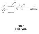
- FIG. 1is an example of prior art electrosurgical device systems.
- FIG. 2is a wireless electrosurgery instrument system constructed in accordance with the principles of the present invention.
- FIG. 3is a surgeon's glove serving as a coupling mechanism adapted for coupling the wireless electrosurgery instrument to a remote power source.
- FIG. 4is a schematic diagram illustrating the operating mode of the current wireless electrosurgery instrument system.
- FIG. 5is a switching/receiver unit for the wireless electrosurgery instrument.
- FIG. 6is a detailed block diagram including an end effector for the wireless electrosurgery instrument.
- FIG. 7is a dual function signals transmission and receiving sequence.
- FIG. 8is a block diagram of switches and basic system elements for dual cut and coagulation functions.
- FIG. 9is a perspective view of a simulated electrosurgery operation using the wireless electrosurgery device system of the present invention.
- FIGS. 1 to 9what is shown is an embodiment of the wireless electrosurgical device system comprising a wireless instrument, a coupling mechanism and a remote power source.
- FIG. 1shows an example of prior art electrosurgical device systems.
- surgical cauteryis mainly performed electrically with a monopolar cautery instrument, though bipolar cautery instruments are also used occasionally.
- the prior art instrumenttransforms hospital available AC power (100 to 250VAC approximately, dependent upon the country) into low current electricity, high frequency (including radiofrequency) waveforms to cut through and/or to coagulate tissue.
- the cutting and coagulating waveformsare delivered to the tissue through a cautery scalpel that plugs into the cautery power supply through a standard cautery interface.
- There is a switch on the cautery scalpelthat a practitioner or surgeon uses to close the appropriate circuit for either cutting or coagulation.
- a wired cautery instrument 11 with its attached wire or electrical cord 12 and a connector 13is plugged into a standard electrosurgery power supply (EPSU) 14 or indirectly connected to a remote power source 15 .
- the standard electrosurgery power supply in this inventioncan be a high frequency power generator, such as a radiofrequency generator.
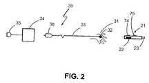
- FIG. 2shows a wireless electrosurgery instrument system constructed in accordance with the principles of the present invention.
- the remotely wired electrosurgical device systemcomprises a wireless electrosurgery instrument 21 having a transmitter and a remote power source 15 , wherein the wireless instrument 21 comprises an end effector 23 and at least one surface electrical contact 22 for contactably coupling the wireless instrument to the remote power source through a coupling mechanism 39 .
- the term “contactably coupling” as referred in this inventionis defined as coupling two electrical contact elements by contacting without plugging or connection.
- 5,961,514discloses a cordless electrosurgical instrument that uses a trocar or trocar adapter as a coupling element for power supply, wherein the trocar or trocar adapter needs to plug into the electrosurgery instrument using an extra hand. Loose wires from the trocar adapter become a troublesome problem to the surgeon. On the contrary, the wireless instrument of the present invention has neither loose wires to interfere with the surgeon's hand motions nor does it contain a battery-pack.
- the coupling mechanism 39may comprise a surgery glove 31 to be worn by a surgeon for performing electrosurgery on a patient and a plug 38 to be connected to a switching/receiver 34 , which is electrically connected through an end plug 35 to and becomes an additional component of the generator 14 and remote power source 15 .
- the switching/receivermay be enclosed within an EPSU 14 or otherwise stand-alone.
- the surgery glove 31has at least one electrically conductive patch zone 32 located at an outer surface of the glove for “contactably coupling” the wireless instrument to the remote power source through an attached conductor wire 33 . As shown in FIG.
- a second electrically conductive patch zone 36 on the glove surfacemay be provided for contactably coupling a second of the at least one surface electrical contact 22 of the bipolar wireless instrument to the remote power source 15 as a returning conductor wire.
- the wireless instrument 21may also comprise an end effector 23 , the end effector being electrically coupled to one of the at least one surface electric contact 22 through a first internal conducting wire within the instrument (not shown). Therefore, a complete circuit is established by a returning electrode 52 normally placed contactably under the patient and returning the current to the standard electrosurgery power supply unit (EPSU) 14 .
- the end effector 23further comprises a returning electrode which is connected through a second internal conducting wire within the instrument to a second of the at least one surface electrical contact 22 for contactably coupling the wireless instrument to the remote power source through the coupling mechanism 39 .
- the coupling mechanism 39that may comprise at least one conducting wire, may be disposable or sterilized for re-use.
- the end effectormay include the distal portion of an electrosurgery instrument, such as bipolar forceps, bipolar scissors, a monopolar hook, monopolar scissors, bipolar endocutters, an electric coagulator, or the like.
- the wireless instrumentmay be a scalpel that has an actuator mounted on said scalpel, the actuator being adapted for activating and deactivating the remote power source.
- a small batterysuch as an AAA size battery is optionally included in the end effector for light bulb use and for activating the feedback circuit.
- FIG. 3shows a surgeon's glove serving as a coupling mechanism 39 adapted for coupling the wireless electrosurgery instrument 21 to a remote power source 15 .
- the glovemay comprise at least an insulated glove conductor 37 having a first end 37 A and a second end 37 B, the first end of the insulated glove conductor being connected to the electrically conductive patch zone 32 of the glove and the second end of the insulated glove conductor being coupled to the remote power source optionally through the EPSU 14 .
- the device systemfurther comprises a gown 81 (as shown in FIG. 9) having an insulated gown conductor 82 , the insulated gown conductor being positioned between the second end 37 B of the insulated glove conductor 37 and the remote power source 15 through the EPSU 14 .
- a monopolar electrosurgery instrument with cautery powerdelivered from a standard electrosurgery power supply unit to which the wireless instruments interfaced, to the wireless instrument through an insulated conductor attached to the surgeon's glove and gown.
- the insulated conductorcould be built into the glove and/or gown or attached on top of it with glue, Velcro® tape or other fixation technique.
- the insulated gown conductorcould be right-handed, left-handed or both-handed.
- the insulated conducting wirescould be placed inside or outside of the gloves or gown.
- the remotely wired electrosurgical device system of the present inventionconsists at least one of the following elements: an end effector that may contact the tissue for electrosurgery operation in either a monopolar fashion or a bipolar fashion, a control circuitry, signaling mechanism, light and driving circuit, and power source.
- FIG. 4shows a schematic diagram illustrating the operating mode of the current wireless electrosurgery instrument.
- a patient 51has a returning electrode 52 for returning the electrical current back to the standard electrosurgery power supply unit (EPSU) 14 .
- the EPSUhas typically a plurality of ports to receive electricity from the power source and the return current from the patient's ground, as well as the output ports (for example, three banana jacks in the standard model) to which the coupling mechanism 39 interfaces. This same interface is used to connect to the switching/receiver unit 34 .
- the wireless instrument 21is remotely wired to the EPSU 14 by a coupling mechanism 39 in a “contactably coupling” fashion 84 .
- the switching/receiver unit 34receives the signal from a transmitter 71 mounted at or adjacent the wireless instrument 21 .
- the switching/receiver unit as shown in FIG. 5comprises a receiver for the signals sent from the electronics in the wireless instrument either through RF or IR methods or along the line.
- the signals receivedare filtered through a signal filter 63 to activate the receiver relay 85 for power supply from the main power line 66 to the end effector.
- the interface 65 to EPSUis positioned between the EPSU 14 and the switching/receiver unit 34 .
- FIG. 6shows a detailed block diagram including an end effector 23 for the wireless electrosurgery instrument 21 .
- a transmitter subsystem 71emits the signals for a desired cutting or cautery function to the switching/receiver unit 34 .
- a light 76is generally provided for the surgeon to better see the surgical site.
- the switching/receiver unit 34After receiving and filtering the signal, the switching/receiver unit 34 then energize the circuits necessary to power oscillators attached to the main power line 66 for supplying the power to the end effector 23 of the wireless instrument 21 .
- At least two of the push-button switchesare located at the wireless instrument for different functions, such as cut, cautery or coagulation.
- a cut switch 74 or a cautery switch 75is depressed to activate a cut signal generator 72 or a cautery signal generator 73 , followed by transmitting the signal to the switching/receiver unit 34 for power energizing.
- the communicating/signaling method of the present inventionmay be selected from a group consisting of (a) infrared transmission, (b) short range radio frequency signaling, and (c) monopolar end effector using capacitive coupling of signals.
- Other communication/signal transmission methodssuch as voice activation, sound, ultrasound, light, laser, foot-switching activation, or the like are also applicable in the present invention.
- the infrared transmission techniqueused infrared LEDs to transmit light pulses to perform the signaling and communication. Different signals for cutting, coagulating, inactive, or other function are made by varying the flashing frequency or other timing characteristics.
- This communicationcould be done at very short range from one or several LEDs, possibly being arranged to form an optimized spreading of the light power, aimed at a receiver on the surgeon's glove. At the expense of power and the risk of line-of-sight blocking of the signal, this communication could also be done over a greater distance from a transmitter on top of the instrument to a receiver in a line-of-sight unobstructed location somewhere else in the operating suite.
- the receiver(a phototransistor or other infra-red sensitive device) transduces the signal into something understandable by a microprocessor or other electronic circuitry. These electrical signals are then interpreted and the appropriate switches closed to turn on the desired electrosurgery operation.
- This method of signalinghas the limitations of interference by blocking of the signal forcing the transmitter to be close to the receiver, and through this limitation the necessity for extra wiring (including the receiver) being attached to the surgeon's arm.
- the short range RF transmission techniquewould work in much the same way but would instead use a RF transmitter located in the wireless electrosurgery instrument to transmit commands to a receiver.
- the receivercould be located on the surgeon's gown or elsewhere in the operating suite.
- the size and range of the antennae necessarywould vary with the frequency permissible by the hospital and appropriate international standards.
- a good example of a system using short range RF transmissionis a Bluetooth wireless mouse for a PC computer.
- Another alternativeis the one which integrates the signal and power delivery into the same conductor. This eliminates the requirement of a second set of wires on the user and the inconvenience of positioning them and maintaining appropriate orientations.
- the transmitter in the wireless instrument in the user's hands and the receiver at the EPSUare now connected directly through a single conductor.
- the transmitterconsists of circuitry to create voltage pulses of different time lengths depending on which task, for example, cut or coagulate, that the user wishes to perform.
- Receivercontains electronics to determine which frequency broadcast would still use capacitive coupling and switches to protect the electronics.
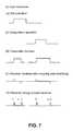
- This operating modeis shown in FIG. 7 where the user indicates a cut and then a coagulate operation.
- “t 1 ”indicates the time for cut signal
- “t 2 ”indicates the time for coagulation signal. Note that these signals could be on the order of microseconds or less and as such the operations are separated as they would most likely not occur so close together in time.
- the operating sequence as shown in FIG. 7includes (A) user indication; (B) transmitter function; (C) receiver receiving after coupling and amplifying; and (D) receiver timing and processing circuitry receiving.
- the time required to indicate each operation modecould vary provided that there is still a sufficient difference in time length between the two signal types. After receiving and interpreting its orders, the selected operation would be carried out for a period of time, a number of multiples of the signaling time chosen to be long enough to achieve efficiency of operation and to remove noticeable and inconvenient delays from the user, and short enough so as to be turned off when no longer desired. This can be seen to form each operation into a packet of time consisting of signaling, delay to setup, operation, and delay to reset.
- the exact time taken for each of these pulseswould be arranged between the transmitter and receiver in a calibration procedure at the start of any operation and before use.
- the transmittersends to the receiver pulses for cutting, coagulation and for the amount of time that the operation will take place—the “on-time”.
- the receiverreceives each of these, measures them and stores for future comparison the amount of time each takes. This will facilitate coordination between the receiver and transmitter, removing the possibility of the transmitter circuitry being connected to (not isolated from) the conductor when the cautery waveform is applied.
- the transmitter 71 and receiver 62are shown having outputs to various relays 87 , 88 , 89 , 90 .
- the transmittercontrols a relay 87 that switches contact with the monopole between the transmitter and the cautery blade, an end effector 23 .
- the receivercontrols two relays: one relay that controls the type of cautery input (either cutting 89 or coagulation 90 ) and another relay 88 that switches monopole contact between the receiver and the cautery input.
- relaysare set to make the connection between the transmitter and receiver. After the user indicates their desired function and the transmitter transmits it, the transmitter activates relay 87 to connect up the end effector. Simultaneously, the valid timing signal is received at the receiver 62 and the receiver disconnects itself and connects one of the cut or coagulation inputs to the monopole direct to the end effector, and from there the signal passes into the patient.
- the receiverdisconnects the cautery signal input and the transmitter reconnects itself to the monopole.
- the transmitterthen waits for the user to give more input and the receiver waits for the transmitter to send a signal. Or should the user be holding the switch indicating an operation, the process begins again immediately. There is no confusion here for the receiver as to when to begin as the transmitter drives the process entirely.
- An error correction schemecould be set up using the time lengths stored from the calibration procedure as normal points and allow some variation in time from these.
- FIG. 9shows a perspective view of a simulated operation using the wireless electrosurgery device system of the present invention.
- a surgeon who holds a wireless electrosurgery instrument 21has a coupling mechanism 39 comprising a glove 31 and/or a gown 81 of the present invention.
- the electrosurgery operationwould become a complete circuit only when both the electrosurgery instrument contacts a patient who has a return electrode and the surgeon sends out a signal from the transmitter to activate the main power line through the EPSU 14 .
- the key advantage of the present invention over the prior artis its relative safety.
- the remotely wired electrosurgical device system of the present inventioncan only be activated by a surgeon or operator who has the coupling mechanism on his surgical glove and/or surgical gown. It is apparent that someone who picks up the instrument and depresses the transmitter button will not activate the instrument. This serves as a safety protection that is not available in other electrosurgical apparatus.
Landscapes
- Health & Medical Sciences (AREA)
- Surgery (AREA)
- Engineering & Computer Science (AREA)
- Life Sciences & Earth Sciences (AREA)
- Biomedical Technology (AREA)
- Otolaryngology (AREA)
- Nuclear Medicine, Radiotherapy & Molecular Imaging (AREA)
- Plasma & Fusion (AREA)
- Physics & Mathematics (AREA)
- Heart & Thoracic Surgery (AREA)
- Medical Informatics (AREA)
- Molecular Biology (AREA)
- Animal Behavior & Ethology (AREA)
- General Health & Medical Sciences (AREA)
- Public Health (AREA)
- Veterinary Medicine (AREA)
- Surgical Instruments (AREA)
Abstract
Description
Claims (23)
Priority Applications (3)
| Application Number | Priority Date | Filing Date | Title |
|---|---|---|---|
| US09/803,284US6551312B2 (en) | 2001-03-09 | 2001-03-09 | Wireless electrosurgical device and methods thereof |
| US09/957,375US6569163B2 (en) | 2001-03-09 | 2001-09-20 | Wireless electrosurgical adapter unit and methods thereof |
| PCT/US2002/007722WO2002071925A2 (en) | 2001-03-09 | 2002-03-05 | Wireless electrosurgical device and methods thereof |
Applications Claiming Priority (1)
| Application Number | Priority Date | Filing Date | Title |
|---|---|---|---|
| US09/803,284US6551312B2 (en) | 2001-03-09 | 2001-03-09 | Wireless electrosurgical device and methods thereof |
Related Child Applications (1)
| Application Number | Title | Priority Date | Filing Date |
|---|---|---|---|
| US09/957,375Continuation-In-PartUS6569163B2 (en) | 2001-03-09 | 2001-09-20 | Wireless electrosurgical adapter unit and methods thereof |
Publications (2)
| Publication Number | Publication Date |
|---|---|
| US20020128646A1 US20020128646A1 (en) | 2002-09-12 |
| US6551312B2true US6551312B2 (en) | 2003-04-22 |
Family
ID=25186117
Family Applications (1)
| Application Number | Title | Priority Date | Filing Date |
|---|---|---|---|
| US09/803,284Expired - Fee RelatedUS6551312B2 (en) | 2001-03-09 | 2001-03-09 | Wireless electrosurgical device and methods thereof |
Country Status (1)
| Country | Link |
|---|---|
| US (1) | US6551312B2 (en) |
Cited By (54)
| Publication number | Priority date | Publication date | Assignee | Title |
|---|---|---|---|---|
| US20040260281A1 (en)* | 2002-09-19 | 2004-12-23 | Baxter Chester O. | Finger tip electrosurgical medical device |
| US20060184242A1 (en)* | 2003-10-20 | 2006-08-17 | Samuel Lichtenstein | Method and apparatus for percutaneous reduction of anterior-posterior diameter of mitral valve |
| US7128741B1 (en)* | 2003-04-04 | 2006-10-31 | Megadyne Medical Products, Inc. | Methods, systems, and devices for performing electrosurgical procedures |
| US20070008639A1 (en)* | 2005-07-11 | 2007-01-11 | Tdk Corporation | Magnetic recording/reproducing system |
| US20070198058A1 (en)* | 2006-02-21 | 2007-08-23 | Daniel Gelbart | Method and device for closing holes in tissue |
| US20070270688A1 (en)* | 2006-05-19 | 2007-11-22 | Daniel Gelbart | Automatic atherectomy system |
| US20080004697A1 (en)* | 2006-06-28 | 2008-01-03 | Samuel Victor Lichtenstein | Method for anchoring a mitral valve |
| US20080004534A1 (en)* | 2006-06-28 | 2008-01-03 | Daniel Gelbart | Intra-cardiac mapping and ablation method |
| US20080045778A1 (en)* | 2006-08-02 | 2008-02-21 | Samuel Victor Lichtenstein | System for improving diastolic dysfunction |
| US20080082099A1 (en)* | 2006-09-29 | 2008-04-03 | Duane Dickens | Surgical probe and methods for targeted treatment of heart structures |
| CN100455329C (en)* | 2004-02-24 | 2009-01-28 | 岑慧红 | Coronary heat disease therapeutic instrument |
| US20090076597A1 (en)* | 2007-09-19 | 2009-03-19 | Jonathan Micheal Dahlgren | System for mechanical adjustment of medical implants |
| US20090131930A1 (en)* | 2007-11-16 | 2009-05-21 | Daniel Gelbart | Medical device for use in bodily lumens, for example an atrium |
| US20090138003A1 (en)* | 2007-11-28 | 2009-05-28 | Derek Dee Deville | Cordless Medical Cauterization and Cutting Device |
| US20090192441A1 (en)* | 2008-01-25 | 2009-07-30 | Daniel Gelbart | Liposuction system |
| US20090240245A1 (en)* | 2008-03-19 | 2009-09-24 | Derek Dee Deville | Method for Powering a Surgical Instrument |
| US20090240246A1 (en)* | 2008-03-19 | 2009-09-24 | Derek Dee Deville | Cordless Medical Cauterization and Cutting Device |
| US20090287304A1 (en)* | 2008-05-13 | 2009-11-19 | Kardium Inc. | Medical Device for Constricting Tissue or a Bodily Orifice, for example a mitral valve |
| US7931648B2 (en) | 2006-01-19 | 2011-04-26 | Schneider Andrew I | Surgical glove system |
| US8328798B2 (en) | 1999-10-02 | 2012-12-11 | Quantumcor, Inc | Method for treating and repairing mitral valve annulus |
| US8377059B2 (en) | 2007-11-28 | 2013-02-19 | Covidien Ag | Cordless medical cauterization and cutting device |
| US20130226168A1 (en)* | 2012-02-27 | 2013-08-29 | Covidien Lp | Glove with sensory elements incorporated therein for controlling at least one surgical instrument |
| US8758342B2 (en) | 2007-11-28 | 2014-06-24 | Covidien Ag | Cordless power-assisted medical cauterization and cutting device |
| US8940002B2 (en) | 2010-09-30 | 2015-01-27 | Kardium Inc. | Tissue anchor system |
| US8945122B2 (en) | 2010-11-16 | 2015-02-03 | Covidien Lp | Power glove |
| US9011423B2 (en) | 2012-05-21 | 2015-04-21 | Kardium, Inc. | Systems and methods for selecting, activating, or selecting and activating transducers |
| US9050066B2 (en) | 2010-06-07 | 2015-06-09 | Kardium Inc. | Closing openings in anatomical tissue |
| US9072511B2 (en) | 2011-03-25 | 2015-07-07 | Kardium Inc. | Medical kit for constricting tissue or a bodily orifice, for example, a mitral valve |
| US9119633B2 (en) | 2006-06-28 | 2015-09-01 | Kardium Inc. | Apparatus and method for intra-cardiac mapping and ablation |
| US9149337B2 (en) | 2006-01-19 | 2015-10-06 | Andrew I. Schneider | Surgical glove systems and method of using the same |
| US9198592B2 (en) | 2012-05-21 | 2015-12-01 | Kardium Inc. | Systems and methods for activating transducers |
| US9204964B2 (en) | 2009-10-01 | 2015-12-08 | Kardium Inc. | Medical device, kit and method for constricting tissue or a bodily orifice, for example, a mitral valve |
| US9241764B2 (en) | 2011-09-26 | 2016-01-26 | Andrew I. Schneider | Method of making polymeric gloves having embedded surgical support systems and discrete elements |
| US9433460B2 (en) | 2014-05-30 | 2016-09-06 | Bipad, Llc | Electrosurgery actuator |
| US9452016B2 (en) | 2011-01-21 | 2016-09-27 | Kardium Inc. | Catheter system |
| US9480525B2 (en) | 2011-01-21 | 2016-11-01 | Kardium, Inc. | High-density electrode-based medical device system |
| US9492228B2 (en) | 2011-01-21 | 2016-11-15 | Kardium Inc. | Enhanced medical device for use in bodily cavities, for example an atrium |
| USD777925S1 (en) | 2012-01-20 | 2017-01-31 | Kardium Inc. | Intra-cardiac procedure device |
| USD777926S1 (en) | 2012-01-20 | 2017-01-31 | Kardium Inc. | Intra-cardiac procedure device |
| USD778442S1 (en) | 2015-11-19 | 2017-02-07 | Bipad, Llc | Bipolar electrosurgery actuator system |
| US9681813B2 (en) | 2009-07-29 | 2017-06-20 | Dinnos Technology | Neurophysiological stimulation system and methods with wireless communication |
| US9782217B2 (en) | 2008-11-13 | 2017-10-10 | Covidien Ag | Radio frequency generator and method for a cordless medical cauterization and cutting device |
| US9907608B2 (en) | 2013-09-05 | 2018-03-06 | Mitragen, Inc. | Valve treatment devices, systems, and methods |
| US10028783B2 (en) | 2006-06-28 | 2018-07-24 | Kardium Inc. | Apparatus and method for intra-cardiac mapping and ablation |
| US10143527B2 (en) | 2006-01-19 | 2018-12-04 | Andrew I. Schneider | Surgical glove systems and method of using the same |
| US10292781B2 (en) | 2011-09-26 | 2019-05-21 | Andrew I. Schneider | Method of making polymeric gloves having embedded surgical support systems and discrete elements |
| US10363085B2 (en) | 2014-01-30 | 2019-07-30 | Fulmer Instruments, Llc | Surgical cutting device |
| US10368936B2 (en) | 2014-11-17 | 2019-08-06 | Kardium Inc. | Systems and methods for selecting, activating, or selecting and activating transducers |
| US10646268B2 (en) | 2016-08-26 | 2020-05-12 | Bipad, Inc. | Ergonomic actuator for electrosurgical tool |
| US10722184B2 (en) | 2014-11-17 | 2020-07-28 | Kardium Inc. | Systems and methods for selecting, activating, or selecting and activating transducers |
| US10827977B2 (en) | 2012-05-21 | 2020-11-10 | Kardium Inc. | Systems and methods for activating transducers |
| US11259867B2 (en) | 2011-01-21 | 2022-03-01 | Kardium Inc. | High-density electrode-based medical device system |
| US11389232B2 (en) | 2006-06-28 | 2022-07-19 | Kardium Inc. | Apparatus and method for intra-cardiac mapping and ablation |
| US11918272B2 (en) | 2020-03-20 | 2024-03-05 | Billings Clinic | Wirelessly controlled bipolar surgical cautery apparatus |
Families Citing this family (4)
| Publication number | Priority date | Publication date | Assignee | Title |
|---|---|---|---|---|
| DE10347478B4 (en)* | 2003-09-30 | 2006-07-27 | Aesculap Ag & Co. Kg | Surgical finger cap |
| DE102008061418A1 (en)* | 2007-12-12 | 2009-06-18 | Erbe Elektromedizin Gmbh | Apparatus for contactless communication and use of a memory device |
| US20090322680A1 (en)* | 2008-06-30 | 2009-12-31 | Maurizio Sole Festa | Radio frequency pointing device |
| US20110282415A1 (en)* | 2010-05-11 | 2011-11-17 | Searete Llc, A Limited Liability Corporation Of The State Of Delaware | Wearable wireless power transmitter |
Citations (11)
| Publication number | Priority date | Publication date | Assignee | Title |
|---|---|---|---|---|
| US3845771A (en)* | 1973-04-24 | 1974-11-05 | W Vise | Electrosurgical glove |
| US4510939A (en)* | 1982-12-22 | 1985-04-16 | Biosonics, Inc. | Means for transferring electrical energy to and from living tissue |
| US4765343A (en)* | 1985-01-29 | 1988-08-23 | Biosonics, Inc. | Apparatus for transferring electrical energy to and from living tissue |
| US4878493A (en)* | 1983-10-28 | 1989-11-07 | Ninetronix Venture I | Hand-held diathermy apparatus |
| US5242440A (en)* | 1991-07-23 | 1993-09-07 | Shippert Ronald D | Finger controlled switching apparatus |
| US5792138A (en) | 1996-02-22 | 1998-08-11 | Apollo Camera, Llc | Cordless bipolar electrocautery unit with automatic power control |
| US5961514A (en) | 1997-05-14 | 1999-10-05 | Ethicon Endo-Surger, Inc. | Cordless electrosurgical instrument |
| US6039734A (en)* | 1995-10-24 | 2000-03-21 | Gyrus Medical Limited | Electrosurgical hand-held battery-operated instrument |
| US6120501A (en) | 1997-05-14 | 2000-09-19 | Ethicon Endo-Surgery, Inc. | Method and apparatus for applying electrical energy to medical instruments |
| US6235027B1 (en)* | 1999-01-21 | 2001-05-22 | Garrett D. Herzon | Thermal cautery surgical forceps |
| US6423059B1 (en)* | 1999-11-16 | 2002-07-23 | Sulzer Medica Usa Inc. | Radio frequency ablation apparatus with remotely articulating and self-locking electrode wand |
- 2001
- 2001-03-09USUS09/803,284patent/US6551312B2/ennot_activeExpired - Fee Related
Patent Citations (11)
| Publication number | Priority date | Publication date | Assignee | Title |
|---|---|---|---|---|
| US3845771A (en)* | 1973-04-24 | 1974-11-05 | W Vise | Electrosurgical glove |
| US4510939A (en)* | 1982-12-22 | 1985-04-16 | Biosonics, Inc. | Means for transferring electrical energy to and from living tissue |
| US4878493A (en)* | 1983-10-28 | 1989-11-07 | Ninetronix Venture I | Hand-held diathermy apparatus |
| US4765343A (en)* | 1985-01-29 | 1988-08-23 | Biosonics, Inc. | Apparatus for transferring electrical energy to and from living tissue |
| US5242440A (en)* | 1991-07-23 | 1993-09-07 | Shippert Ronald D | Finger controlled switching apparatus |
| US6039734A (en)* | 1995-10-24 | 2000-03-21 | Gyrus Medical Limited | Electrosurgical hand-held battery-operated instrument |
| US5792138A (en) | 1996-02-22 | 1998-08-11 | Apollo Camera, Llc | Cordless bipolar electrocautery unit with automatic power control |
| US5961514A (en) | 1997-05-14 | 1999-10-05 | Ethicon Endo-Surger, Inc. | Cordless electrosurgical instrument |
| US6120501A (en) | 1997-05-14 | 2000-09-19 | Ethicon Endo-Surgery, Inc. | Method and apparatus for applying electrical energy to medical instruments |
| US6235027B1 (en)* | 1999-01-21 | 2001-05-22 | Garrett D. Herzon | Thermal cautery surgical forceps |
| US6423059B1 (en)* | 1999-11-16 | 2002-07-23 | Sulzer Medica Usa Inc. | Radio frequency ablation apparatus with remotely articulating and self-locking electrode wand |
Non-Patent Citations (3)
| Title |
|---|
| Kim DW, "Electric and laser energy for endoscopic surgery" Yonsei Med J 40(6): 536-544, 1999. |
| Weber PJ, et al. "Electrosurgical suspension apparatus" Dermatol Surg 2000; 26:142-145. |
| Zinder DJ, "Common myths about electrosurgery" Otolaryngol Head Neck Surg 2000; 123:450-5. |
Cited By (172)
| Publication number | Priority date | Publication date | Assignee | Title |
|---|---|---|---|---|
| US8328798B2 (en) | 1999-10-02 | 2012-12-11 | Quantumcor, Inc | Method for treating and repairing mitral valve annulus |
| US20070093807A1 (en)* | 2002-09-19 | 2007-04-26 | Baxter Chester O Iii | Finger tip electrosurgical medical device |
| US20040260281A1 (en)* | 2002-09-19 | 2004-12-23 | Baxter Chester O. | Finger tip electrosurgical medical device |
| US7128741B1 (en)* | 2003-04-04 | 2006-10-31 | Megadyne Medical Products, Inc. | Methods, systems, and devices for performing electrosurgical procedures |
| US20070060919A1 (en)* | 2003-04-04 | 2007-03-15 | Megadyne Medical Products, Inc. | Methods, systems, and devices for performing electrosurgical procedures |
| US8932280B2 (en)* | 2003-04-04 | 2015-01-13 | Megadyne Medical Products, Inc. | Methods, systems and devices for performing electrosurgical procedures |
| US20110125152A1 (en)* | 2003-04-04 | 2011-05-26 | Isaacson James D | Methods, systems and devices for performing electrosurgical procedures |
| US7842033B2 (en)* | 2003-04-04 | 2010-11-30 | Megadyne Medical Products, Inc. | Methods, systems, and devices for performing electrosurgical procedures |
| US20060184242A1 (en)* | 2003-10-20 | 2006-08-17 | Samuel Lichtenstein | Method and apparatus for percutaneous reduction of anterior-posterior diameter of mitral valve |
| CN100455329C (en)* | 2004-02-24 | 2009-01-28 | 岑慧红 | Coronary heat disease therapeutic instrument |
| US20070008639A1 (en)* | 2005-07-11 | 2007-01-11 | Tdk Corporation | Magnetic recording/reproducing system |
| US10653493B2 (en) | 2006-01-19 | 2020-05-19 | Andrew I. Schneider | Surgical glove systems and method of using the same |
| US7931648B2 (en) | 2006-01-19 | 2011-04-26 | Schneider Andrew I | Surgical glove system |
| US10143527B2 (en) | 2006-01-19 | 2018-12-04 | Andrew I. Schneider | Surgical glove systems and method of using the same |
| US8449541B2 (en) | 2006-01-19 | 2013-05-28 | Andrew I. Schneider | Surgical glove system |
| US8182479B2 (en) | 2006-01-19 | 2012-05-22 | Schneider Andrew I | Surgical glove system |
| US20110191935A1 (en)* | 2006-01-19 | 2011-08-11 | Schneider Andrew I | Surgical glove system |
| US9149337B2 (en) | 2006-01-19 | 2015-10-06 | Andrew I. Schneider | Surgical glove systems and method of using the same |
| US7951145B2 (en) | 2006-01-19 | 2011-05-31 | Schneider Andrew I | Surgical glove system |
| US7749249B2 (en) | 2006-02-21 | 2010-07-06 | Kardium Inc. | Method and device for closing holes in tissue |
| US20100222789A1 (en)* | 2006-02-21 | 2010-09-02 | Kardium Inc. | Method and device for closing holes in tissue |
| US20070198058A1 (en)* | 2006-02-21 | 2007-08-23 | Daniel Gelbart | Method and device for closing holes in tissue |
| US9572557B2 (en) | 2006-02-21 | 2017-02-21 | Kardium Inc. | Method and device for closing holes in tissue |
| US8337524B2 (en) | 2006-02-21 | 2012-12-25 | Kardium Inc. | Method and device for closing holes in tissue |
| US8150499B2 (en) | 2006-05-19 | 2012-04-03 | Kardium Inc. | Automatic atherectomy system |
| US8532746B2 (en) | 2006-05-19 | 2013-09-10 | Kardium Inc. | Automatic atherectomy system |
| US20070270688A1 (en)* | 2006-05-19 | 2007-11-22 | Daniel Gelbart | Automatic atherectomy system |
| US20110125172A1 (en)* | 2006-05-19 | 2011-05-26 | Kardium Inc. | Automatic atherectomy system |
| US8920411B2 (en) | 2006-06-28 | 2014-12-30 | Kardium Inc. | Apparatus and method for intra-cardiac mapping and ablation |
| US8449605B2 (en) | 2006-06-28 | 2013-05-28 | Kardium Inc. | Method for anchoring a mitral valve |
| US10828094B2 (en) | 2006-06-28 | 2020-11-10 | Kardium Inc. | Apparatus and method for intra-cardiac mapping and ablation |
| US11389232B2 (en) | 2006-06-28 | 2022-07-19 | Kardium Inc. | Apparatus and method for intra-cardiac mapping and ablation |
| US9987084B2 (en) | 2006-06-28 | 2018-06-05 | Kardium Inc. | Apparatus and method for intra-cardiac mapping and ablation |
| US20080004697A1 (en)* | 2006-06-28 | 2008-01-03 | Samuel Victor Lichtenstein | Method for anchoring a mitral valve |
| US10828093B2 (en) | 2006-06-28 | 2020-11-10 | Kardium Inc. | Apparatus and method for intra-cardiac mapping and ablation |
| US9192468B2 (en) | 2006-06-28 | 2015-11-24 | Kardium Inc. | Method for anchoring a mitral valve |
| US10820941B2 (en) | 2006-06-28 | 2020-11-03 | Kardium Inc. | Apparatus and method for intra-cardiac mapping and ablation |
| US11389231B2 (en) | 2006-06-28 | 2022-07-19 | Kardium Inc. | Apparatus and method for intra-cardiac mapping and ablation |
| US11399890B2 (en) | 2006-06-28 | 2022-08-02 | Kardium Inc. | Apparatus and method for intra-cardiac mapping and ablation |
| US9119633B2 (en) | 2006-06-28 | 2015-09-01 | Kardium Inc. | Apparatus and method for intra-cardiac mapping and ablation |
| US9119634B2 (en) | 2006-06-28 | 2015-09-01 | Kardium Inc. | Apparatus and method for intra-cardiac mapping and ablation |
| US10028783B2 (en) | 2006-06-28 | 2018-07-24 | Kardium Inc. | Apparatus and method for intra-cardiac mapping and ablation |
| US20080004534A1 (en)* | 2006-06-28 | 2008-01-03 | Daniel Gelbart | Intra-cardiac mapping and ablation method |
| US8672998B2 (en) | 2006-06-28 | 2014-03-18 | Kardium Inc. | Method for anchoring a mitral valve |
| US9987083B2 (en) | 2006-06-28 | 2018-06-05 | Kardium Inc. | Apparatus and method for intra-cardiac mapping and ablation |
| US7837610B2 (en) | 2006-08-02 | 2010-11-23 | Kardium Inc. | System for improving diastolic dysfunction |
| US20110087203A1 (en)* | 2006-08-02 | 2011-04-14 | Kardium Inc. | System for improving diastolic dysfunction |
| US20080045778A1 (en)* | 2006-08-02 | 2008-02-21 | Samuel Victor Lichtenstein | System for improving diastolic dysfunction |
| US11033392B2 (en) | 2006-08-02 | 2021-06-15 | Kardium Inc. | System for improving diastolic dysfunction |
| US8187266B2 (en) | 2006-09-29 | 2012-05-29 | Quantumcor, Inc. | Surgical probe and methods for targeted treatment of heart structures |
| US20080082099A1 (en)* | 2006-09-29 | 2008-04-03 | Duane Dickens | Surgical probe and methods for targeted treatment of heart structures |
| US20090076597A1 (en)* | 2007-09-19 | 2009-03-19 | Jonathan Micheal Dahlgren | System for mechanical adjustment of medical implants |
| US10828096B2 (en) | 2007-11-16 | 2020-11-10 | Kardium Inc. | Medical device for use in bodily lumens, for example an atrium |
| US11331141B2 (en) | 2007-11-16 | 2022-05-17 | Kardium Inc. | Medical device for use in bodily lumens, for example an atrium |
| US11801091B2 (en) | 2007-11-16 | 2023-10-31 | Kardium Inc. | Medical device for use in bodily lumens, for example an atrium |
| US11751940B2 (en) | 2007-11-16 | 2023-09-12 | Kardium Inc. | Medical device for use in bodily lumens, for example an atrium |
| US11633231B2 (en) | 2007-11-16 | 2023-04-25 | Kardium Inc. | Medical device for use in bodily lumens, for example an atrium |
| US11432874B2 (en) | 2007-11-16 | 2022-09-06 | Kardium Inc. | Medical device for use in bodily lumens, for example an atrium |
| US11413091B2 (en) | 2007-11-16 | 2022-08-16 | Kardium Inc. | Medical device for use in bodily lumens, for example an atrium |
| US20090131930A1 (en)* | 2007-11-16 | 2009-05-21 | Daniel Gelbart | Medical device for use in bodily lumens, for example an atrium |
| US11304751B2 (en) | 2007-11-16 | 2022-04-19 | Kardium Inc. | Medical device for use in bodily lumens, for example an atrium |
| US11076913B2 (en) | 2007-11-16 | 2021-08-03 | Kardium Inc. | Medical device for use in bodily lumens, for example an atrium |
| US10828097B2 (en) | 2007-11-16 | 2020-11-10 | Kardium Inc. | Medical device for use in bodily lumens, for example an atrium |
| US10828095B2 (en) | 2007-11-16 | 2020-11-10 | Kardium Inc. | Medical device for use in bodily lumens, for example an atrium |
| US10828098B2 (en) | 2007-11-16 | 2020-11-10 | Kardium Inc. | Medical device for use in bodily lumens, for example an atrium |
| US10499986B2 (en) | 2007-11-16 | 2019-12-10 | Kardium Inc. | Medical device for use in bodily lumens, for example an atrium |
| US8906011B2 (en) | 2007-11-16 | 2014-12-09 | Kardium Inc. | Medical device for use in bodily lumens, for example an atrium |
| US9877779B2 (en) | 2007-11-16 | 2018-01-30 | Kardium Inc. | Medical device for use in bodily lumens, for example an atrium |
| US9839474B2 (en) | 2007-11-16 | 2017-12-12 | Kardium Inc. | Medical device for use in bodily lumens, for example an atrium |
| US9820810B2 (en) | 2007-11-16 | 2017-11-21 | Kardium Inc. | Medical device for use in bodily lumens, for example an atrium |
| US9750569B2 (en) | 2007-11-16 | 2017-09-05 | Kardium Inc. | Medical device for use in bodily lumens, for example an atrium |
| US9603661B2 (en) | 2007-11-16 | 2017-03-28 | Kardium Inc. | Medical device for use in bodily lumens, for example an atrium |
| US9585717B2 (en) | 2007-11-16 | 2017-03-07 | Kardium Inc. | Medical device for use in bodily lumens, for example an atrium |
| US8932287B2 (en) | 2007-11-16 | 2015-01-13 | Kardium Inc. | Medical device for use in bodily lumens, for example an atrium |
| US8758342B2 (en) | 2007-11-28 | 2014-06-24 | Covidien Ag | Cordless power-assisted medical cauterization and cutting device |
| US10022180B2 (en) | 2007-11-28 | 2018-07-17 | Covidien Ag | Cordless medical cauterization and cutting device |
| US9532829B2 (en) | 2007-11-28 | 2017-01-03 | Covidien Ag | Cordless medical cauterization and cutting device |
| US9050098B2 (en) | 2007-11-28 | 2015-06-09 | Covidien Ag | Cordless medical cauterization and cutting device |
| US8377059B2 (en) | 2007-11-28 | 2013-02-19 | Covidien Ag | Cordless medical cauterization and cutting device |
| US20090138003A1 (en)* | 2007-11-28 | 2009-05-28 | Derek Dee Deville | Cordless Medical Cauterization and Cutting Device |
| US20090192441A1 (en)* | 2008-01-25 | 2009-07-30 | Daniel Gelbart | Liposuction system |
| US8489172B2 (en) | 2008-01-25 | 2013-07-16 | Kardium Inc. | Liposuction system |
| US8491581B2 (en) | 2008-03-19 | 2013-07-23 | Covidien Ag | Method for powering a surgical instrument |
| US20090240246A1 (en)* | 2008-03-19 | 2009-09-24 | Derek Dee Deville | Cordless Medical Cauterization and Cutting Device |
| US20090240245A1 (en)* | 2008-03-19 | 2009-09-24 | Derek Dee Deville | Method for Powering a Surgical Instrument |
| US8328802B2 (en) | 2008-03-19 | 2012-12-11 | Covidien Ag | Cordless medical cauterization and cutting device |
| US20090287304A1 (en)* | 2008-05-13 | 2009-11-19 | Kardium Inc. | Medical Device for Constricting Tissue or a Bodily Orifice, for example a mitral valve |
| US9744038B2 (en) | 2008-05-13 | 2017-08-29 | Kardium Inc. | Medical device for constricting tissue or a bodily orifice, for example a mitral valve |
| US10987158B2 (en) | 2008-11-13 | 2021-04-27 | Covidien Ag | Radio frequency surgical system |
| US9782217B2 (en) | 2008-11-13 | 2017-10-10 | Covidien Ag | Radio frequency generator and method for a cordless medical cauterization and cutting device |
| US9681813B2 (en) | 2009-07-29 | 2017-06-20 | Dinnos Technology | Neurophysiological stimulation system and methods with wireless communication |
| US9204964B2 (en) | 2009-10-01 | 2015-12-08 | Kardium Inc. | Medical device, kit and method for constricting tissue or a bodily orifice, for example, a mitral valve |
| US10813758B2 (en) | 2009-10-01 | 2020-10-27 | Kardium Inc. | Medical device, kit and method for constricting tissue or a bodily orifice, for example, a mitral valve |
| US9867703B2 (en) | 2009-10-01 | 2018-01-16 | Kardium Inc. | Medical device, kit and method for constricting tissue or a bodily orifice, for example, a mitral valve |
| US10687941B2 (en) | 2009-10-01 | 2020-06-23 | Kardium Inc. | Medical device, kit and method for constricting tissue or a bodily orifice, for example, a mitral valve |
| US10603022B2 (en) | 2010-06-07 | 2020-03-31 | Kardium Inc. | Closing openings in anatomical tissue |
| US9918706B2 (en) | 2010-06-07 | 2018-03-20 | Kardium Inc. | Closing openings in anatomical tissue |
| US9050066B2 (en) | 2010-06-07 | 2015-06-09 | Kardium Inc. | Closing openings in anatomical tissue |
| US8940002B2 (en) | 2010-09-30 | 2015-01-27 | Kardium Inc. | Tissue anchor system |
| US8945122B2 (en) | 2010-11-16 | 2015-02-03 | Covidien Lp | Power glove |
| US11399881B2 (en) | 2011-01-21 | 2022-08-02 | Kardium Inc. | Enhanced medical device for use in bodily cavities, for example an atrium |
| US11350989B2 (en) | 2011-01-21 | 2022-06-07 | Kardium Inc. | Catheter system |
| US12383325B2 (en) | 2011-01-21 | 2025-08-12 | Kardium Inc. | Enhanced medical device for use in bodily cavities, for example an atrium |
| US9480525B2 (en) | 2011-01-21 | 2016-11-01 | Kardium, Inc. | High-density electrode-based medical device system |
| US9486273B2 (en) | 2011-01-21 | 2016-11-08 | Kardium Inc. | High-density electrode-based medical device system |
| US12349955B2 (en) | 2011-01-21 | 2025-07-08 | Kardium Inc. | Enhanced medical device for use in bodily cavities, for example an atrium |
| US9452016B2 (en) | 2011-01-21 | 2016-09-27 | Kardium Inc. | Catheter system |
| US12178490B2 (en) | 2011-01-21 | 2024-12-31 | Kardium Inc. | Enhanced medical device for use in bodily cavities, for example an atrium |
| US12059202B2 (en) | 2011-01-21 | 2024-08-13 | Kardium Inc. | Catheter system |
| US11896295B2 (en) | 2011-01-21 | 2024-02-13 | Kardium Inc. | High-density electrode-based medical device system |
| US9526573B2 (en) | 2011-01-21 | 2016-12-27 | Kardium Inc. | Enhanced medical device for use in bodily cavities, for example an atrium |
| US10485608B2 (en) | 2011-01-21 | 2019-11-26 | Kardium Inc. | Catheter system |
| US9492228B2 (en) | 2011-01-21 | 2016-11-15 | Kardium Inc. | Enhanced medical device for use in bodily cavities, for example an atrium |
| US11259867B2 (en) | 2011-01-21 | 2022-03-01 | Kardium Inc. | High-density electrode-based medical device system |
| US11607261B2 (en) | 2011-01-21 | 2023-03-21 | Kardium Inc. | Enhanced medical device for use in bodily cavities, for example an atrium |
| US11596463B2 (en) | 2011-01-21 | 2023-03-07 | Kardium Inc. | Enhanced medical device for use in bodily cavities, for example an atrium |
| US9492227B2 (en) | 2011-01-21 | 2016-11-15 | Kardium Inc. | Enhanced medical device for use in bodily cavities, for example an atrium |
| US11298173B2 (en) | 2011-01-21 | 2022-04-12 | Kardium Inc. | Enhanced medical device for use in bodily cavities, for example an atrium |
| US9675401B2 (en) | 2011-01-21 | 2017-06-13 | Kardium Inc. | Enhanced medical device for use in bodily cavities, for example an atrium |
| US9072511B2 (en) | 2011-03-25 | 2015-07-07 | Kardium Inc. | Medical kit for constricting tissue or a bodily orifice, for example, a mitral valve |
| US10058318B2 (en) | 2011-03-25 | 2018-08-28 | Kardium Inc. | Medical kit for constricting tissue or a bodily orifice, for example, a mitral valve |
| US20160174636A1 (en)* | 2011-09-26 | 2016-06-23 | Andrew I. Schneider | Method of making polymeric gloves having embedded surgical support systems and discrete elements |
| US10292781B2 (en) | 2011-09-26 | 2019-05-21 | Andrew I. Schneider | Method of making polymeric gloves having embedded surgical support systems and discrete elements |
| US9241764B2 (en) | 2011-09-26 | 2016-01-26 | Andrew I. Schneider | Method of making polymeric gloves having embedded surgical support systems and discrete elements |
| USD777926S1 (en) | 2012-01-20 | 2017-01-31 | Kardium Inc. | Intra-cardiac procedure device |
| USD777925S1 (en) | 2012-01-20 | 2017-01-31 | Kardium Inc. | Intra-cardiac procedure device |
| US9445876B2 (en)* | 2012-02-27 | 2016-09-20 | Covidien Lp | Glove with sensory elements incorporated therein for controlling at least one surgical instrument |
| US20130226168A1 (en)* | 2012-02-27 | 2013-08-29 | Covidien Lp | Glove with sensory elements incorporated therein for controlling at least one surgical instrument |
| US9198592B2 (en) | 2012-05-21 | 2015-12-01 | Kardium Inc. | Systems and methods for activating transducers |
| US9011423B2 (en) | 2012-05-21 | 2015-04-21 | Kardium, Inc. | Systems and methods for selecting, activating, or selecting and activating transducers |
| US10918446B2 (en) | 2012-05-21 | 2021-02-16 | Kardium Inc. | Systems and methods for selecting, activating, or selecting and activating transducers |
| US10827977B2 (en) | 2012-05-21 | 2020-11-10 | Kardium Inc. | Systems and methods for activating transducers |
| US12376795B2 (en) | 2012-05-21 | 2025-08-05 | Kardium Inc. | Systems and methods for activating transducers |
| US12376796B2 (en) | 2012-05-21 | 2025-08-05 | Kardium Inc. | Systems and methods for activating transducers |
| US9259264B2 (en) | 2012-05-21 | 2016-02-16 | Kardium Inc. | Systems and methods for activating transducers |
| US11690684B2 (en) | 2012-05-21 | 2023-07-04 | Kardium Inc. | Systems and methods for selecting, activating, or selecting and activating transducers |
| US11805974B2 (en) | 2012-05-21 | 2023-11-07 | Kardium Inc. | Systems and methods for selecting, activating, or selecting and activating transducers |
| US11154248B2 (en) | 2012-05-21 | 2021-10-26 | Kardium Inc. | Systems and methods for activating transducers |
| US9445862B2 (en) | 2012-05-21 | 2016-09-20 | Kardium Inc. | Systems and methods for selecting, activating, or selecting and activating transducers |
| US9980679B2 (en) | 2012-05-21 | 2018-05-29 | Kardium Inc. | Systems and methods for activating transducers |
| US9572509B2 (en) | 2012-05-21 | 2017-02-21 | Kardium Inc. | Systems and methods for activating transducers |
| US9017321B2 (en) | 2012-05-21 | 2015-04-28 | Kardium, Inc. | Systems and methods for activating transducers |
| US12324636B2 (en) | 2012-05-21 | 2025-06-10 | Kardium Inc. | Systems and methods for selecting, activating, or selecting and activating transducers |
| US9693832B2 (en) | 2012-05-21 | 2017-07-04 | Kardium Inc. | Systems and methods for selecting, activating, or selecting and activating transducers |
| US12226172B2 (en) | 2012-05-21 | 2025-02-18 | Kardium Inc. | Systems and methods for selecting, activating, or selecting and activating transducers |
| US9439713B2 (en) | 2012-05-21 | 2016-09-13 | Kardium Inc. | Systems and methods for activating transducers |
| US9888972B2 (en) | 2012-05-21 | 2018-02-13 | Kardium Inc. | Systems and methods for selecting, activating, or selecting and activating transducers |
| US9532831B2 (en) | 2012-05-21 | 2017-01-03 | Kardium Inc. | Systems and methods for activating transducers |
| US9017320B2 (en) | 2012-05-21 | 2015-04-28 | Kardium, Inc. | Systems and methods for activating transducers |
| US11589821B2 (en) | 2012-05-21 | 2023-02-28 | Kardium Inc. | Systems and methods for activating transducers |
| US10470826B2 (en) | 2012-05-21 | 2019-11-12 | Kardium Inc. | Systems and methods for selecting, activating, or selecting and activating transducers |
| US11672485B2 (en) | 2012-05-21 | 2023-06-13 | Kardium Inc. | Systems and methods for activating transducers |
| US10568576B2 (en) | 2012-05-21 | 2020-02-25 | Kardium Inc. | Systems and methods for activating transducers |
| US11633238B2 (en) | 2012-05-21 | 2023-04-25 | Kardium Inc. | Systems and methods for selecting, activating, or selecting and activating transducers |
| US9907608B2 (en) | 2013-09-05 | 2018-03-06 | Mitragen, Inc. | Valve treatment devices, systems, and methods |
| US9987082B2 (en) | 2013-09-05 | 2018-06-05 | Mitragen, Inc. | Valve treatment devices, systems, and methods |
| US12239357B2 (en) | 2014-01-30 | 2025-03-04 | Fulmer Instruments, Llc | Surgical cutting device |
| US10363085B2 (en) | 2014-01-30 | 2019-07-30 | Fulmer Instruments, Llc | Surgical cutting device |
| US11147609B2 (en) | 2014-01-30 | 2021-10-19 | Fulmer Instruments, Llc | Surgical cutting device |
| US10456192B2 (en) | 2014-05-30 | 2019-10-29 | Bipad, Llc | Bipolar electrosurgery actuator |
| US9433460B2 (en) | 2014-05-30 | 2016-09-06 | Bipad, Llc | Electrosurgery actuator |
| US10368936B2 (en) | 2014-11-17 | 2019-08-06 | Kardium Inc. | Systems and methods for selecting, activating, or selecting and activating transducers |
| US12133745B2 (en) | 2014-11-17 | 2024-11-05 | Kardium Inc. | Systems and methods for selecting, activating, or selecting and activating transducers |
| US10722184B2 (en) | 2014-11-17 | 2020-07-28 | Kardium Inc. | Systems and methods for selecting, activating, or selecting and activating transducers |
| US10751006B2 (en) | 2014-11-17 | 2020-08-25 | Kardium Inc. | Systems and methods for selecting, activating, or selecting and activating transducers |
| US10758191B2 (en) | 2014-11-17 | 2020-09-01 | Kardium Inc. | Systems and methods for selecting, activating, or selecting and activating transducers |
| US11026638B2 (en) | 2014-11-17 | 2021-06-08 | Kardium Inc. | Systems and methods for selecting, activating, or selecting and activating transducers |
| US11026637B2 (en) | 2014-11-17 | 2021-06-08 | Kardium Inc. | Systems and methods for selecting, activating, or selecting and activating transducers |
| US12383208B2 (en) | 2014-11-17 | 2025-08-12 | Kardium Inc. | Systems and methods for selecting, activating, or selecting and activating transducers |
| USD778442S1 (en) | 2015-11-19 | 2017-02-07 | Bipad, Llc | Bipolar electrosurgery actuator system |
| US10646268B2 (en) | 2016-08-26 | 2020-05-12 | Bipad, Inc. | Ergonomic actuator for electrosurgical tool |
| US11918272B2 (en) | 2020-03-20 | 2024-03-05 | Billings Clinic | Wirelessly controlled bipolar surgical cautery apparatus |
Also Published As
| Publication number | Publication date |
|---|---|
| US20020128646A1 (en) | 2002-09-12 |
Similar Documents
| Publication | Publication Date | Title |
|---|---|---|
| US6551312B2 (en) | Wireless electrosurgical device and methods thereof | |
| US6569163B2 (en) | Wireless electrosurgical adapter unit and methods thereof | |
| JP7329032B2 (en) | Illuminated electrosurgical system and method of use | |
| EP1707147B1 (en) | Electrosurgical instrument | |
| US6402747B1 (en) | Handswitch cord and circuit | |
| CA2110684C (en) | Electrosurgical and ultrasonic surgical system | |
| US10278762B2 (en) | Inductive powered surgical device with wireless control | |
| US7828794B2 (en) | Handheld electrosurgical apparatus for controlling operating room equipment | |
| US8945122B2 (en) | Power glove | |
| US20110054462A1 (en) | Electrosurgical instrument with multi-function handpiece | |
| US20090131929A1 (en) | Relay device and ultrasonic-surgical and electrosurgical system | |
| US20080125768A1 (en) | Relay device and ultrasonic-surgical and electrosurgical system | |
| US20110071520A1 (en) | Methods and Apparatus for Smart Handset Design in Surgical Instruments | |
| JP2002306504A (en) | Surgical system | |
| EP2606845B1 (en) | Pulse generator | |
| KR102446776B1 (en) | Simultaneous electrosurgical suture and amputation | |
| US20220226036A1 (en) | Multi-functional surgical cautery device, system and method of use | |
| JP6374952B2 (en) | Electrosurgical instrument for excision of tissue mass from human body and animals | |
| JP2019058662A (en) | System and method for controlling electrosurgical ablation | |
| JP2004049566A (en) | Electrosurgical apparatus | |
| US20220395311A1 (en) | Motion sensing electrosurgical devices | |
| KR101576092B1 (en) | Electrosurgical instrument with over current protection function | |
| JPH08308852A (en) | Electrosurgical device | |
| CA2198313A1 (en) | Handswitch cord and circuit |
Legal Events
| Date | Code | Title | Description |
|---|---|---|---|
| REMI | Maintenance fee reminder mailed | ||
| FPAY | Fee payment | Year of fee payment:4 | |
| SULP | Surcharge for late payment | ||
| AS | Assignment | Owner name:QUANTUMCOR, INC., CALIFORNIA Free format text:ASSIGNMENT OF ASSIGNORS INTEREST;ASSIGNOR:ZHANG, JI;REEL/FRAME:019268/0043 Effective date:20020705 | |
| REMI | Maintenance fee reminder mailed | ||
| LAPS | Lapse for failure to pay maintenance fees | ||
| REIN | Reinstatement after maintenance fee payment confirmed | ||
| FP | Lapsed due to failure to pay maintenance fee | Effective date:20110422 | |
| FEPP | Fee payment procedure | Free format text:PETITION RELATED TO MAINTENANCE FEES GRANTED (ORIGINAL EVENT CODE: PMFG); ENTITY STATUS OF PATENT OWNER: SMALL ENTITY Free format text:PETITION RELATED TO MAINTENANCE FEES FILED (ORIGINAL EVENT CODE: PMFP); ENTITY STATUS OF PATENT OWNER: SMALL ENTITY | |
| PRDP | Patent reinstated due to the acceptance of a late maintenance fee | Effective date:20120203 | |
| FPAY | Fee payment | Year of fee payment:8 | |
| SULP | Surcharge for late payment | ||
| AS | Assignment | Owner name:VALVECURE, INC., CALIFORNIA Free format text:ASSIGNMENT OF ASSIGNORS INTEREST;ASSIGNOR:QUANTUMCOR, INC.;REEL/FRAME:032308/0860 Effective date:20140122 Owner name:QUANTUMCOR, INC., CALIFORNIA Free format text:ASSIGNMENT OF ASSIGNORS INTEREST;ASSIGNOR:LICHTENSTEIN, SAMUAL;REEL/FRAME:032261/0215 Effective date:20050203 | |
| REMI | Maintenance fee reminder mailed | ||
| LAPS | Lapse for failure to pay maintenance fees | ||
| STCH | Information on status: patent discontinuation | Free format text:PATENT EXPIRED DUE TO NONPAYMENT OF MAINTENANCE FEES UNDER 37 CFR 1.362 | |
| FP | Lapsed due to failure to pay maintenance fee | Effective date:20150422 |