US6551311B2 - Cell necrosis apparatus and method - Google Patents
Cell necrosis apparatus and methodDownload PDFInfo
- Publication number
- US6551311B2 US6551311B2US09/758,326US75832601AUS6551311B2US 6551311 B2US6551311 B2US 6551311B2US 75832601 AUS75832601 AUS 75832601AUS 6551311 B2US6551311 B2US 6551311B2
- Authority
- US
- United States
- Prior art keywords
- electrodes
- electrode
- advancement
- introducer
- delivery device
- Prior art date
- Legal status (The legal status is an assumption and is not a legal conclusion. Google has not performed a legal analysis and makes no representation as to the accuracy of the status listed.)
- Expired - Fee Related
Links
- 230000017074necrotic cell deathEffects0.000titleclaimsabstractdescription56
- 238000000034methodMethods0.000titleclaimsdescription21
- 206010028980NeoplasmDiseases0.000claimsdescription22
- 238000010168coupling processMethods0.000claimsdescription8
- 238000005859coupling reactionMethods0.000claimsdescription8
- 238000002679ablationMethods0.000claimsdescription6
- 230000008878couplingEffects0.000claimsdescription5
- 238000005259measurementMethods0.000claimsdescription5
- 230000006870functionEffects0.000claimsdescription2
- 230000003287optical effectEffects0.000claims2
- 210000001519tissueAnatomy0.000description56
- 210000004027cellAnatomy0.000description53
- 238000009413insulationMethods0.000description24
- 125000006850spacer groupChemical group0.000description9
- 230000003902lesionEffects0.000description8
- 238000002604ultrasonographyMethods0.000description6
- 206010020843HyperthermiaDiseases0.000description5
- 230000008859changeEffects0.000description5
- 238000010438heat treatmentMethods0.000description5
- 230000036031hyperthermiaEffects0.000description5
- 238000012544monitoring processMethods0.000description5
- 230000006378damageEffects0.000description3
- 230000007246mechanismEffects0.000description3
- 238000007674radiofrequency ablationMethods0.000description3
- 230000017531blood circulationEffects0.000description2
- 230000000875corresponding effectEffects0.000description2
- 238000010586diagramMethods0.000description2
- 239000003814drugSubstances0.000description2
- 238000003384imaging methodMethods0.000description2
- 239000000463materialSubstances0.000description2
- 230000008569processEffects0.000description2
- 230000009467reductionEffects0.000description2
- 239000007787solidSubstances0.000description2
- 238000001356surgical procedureMethods0.000description2
- 238000012800visualizationMethods0.000description2
- 239000010963304 stainless steelSubstances0.000description1
- RYGMFSIKBFXOCR-UHFFFAOYSA-NCopperChemical compound[Cu]RYGMFSIKBFXOCR-UHFFFAOYSA-N0.000description1
- 238000012369In process controlMethods0.000description1
- 206010027476MetastasesDiseases0.000description1
- 229910000589SAE 304 stainless steelInorganic materials0.000description1
- 239000002246antineoplastic agentSubstances0.000description1
- 230000015572biosynthetic processEffects0.000description1
- 238000009529body temperature measurementMethods0.000description1
- 201000011510cancerDiseases0.000description1
- 210000000170cell membraneAnatomy0.000description1
- 230000001413cellular effectEffects0.000description1
- 239000003795chemical substances by applicationSubstances0.000description1
- 230000001427coherent effectEffects0.000description1
- 239000004020conductorSubstances0.000description1
- 239000002872contrast mediaSubstances0.000description1
- 229910052802copperInorganic materials0.000description1
- 239000010949copperSubstances0.000description1
- 230000002596correlated effectEffects0.000description1
- 230000001086cytosolic effectEffects0.000description1
- 229940127089cytotoxic agentDrugs0.000description1
- 238000013461designMethods0.000description1
- 238000001514detection methodMethods0.000description1
- 238000011161developmentMethods0.000description1
- 102000038379digestive enzymesHuman genes0.000description1
- 108091007734digestive enzymesProteins0.000description1
- 229940079593drugDrugs0.000description1
- 230000000694effectsEffects0.000description1
- 239000008151electrolyte solutionSubstances0.000description1
- 230000003028elevating effectEffects0.000description1
- 230000008029eradicationEffects0.000description1
- 230000005284excitationEffects0.000description1
- 239000000835fiberSubstances0.000description1
- 238000001415gene therapyMethods0.000description1
- 230000001900immune effectEffects0.000description1
- 238000010965in-process controlMethods0.000description1
- 238000001802infusionMethods0.000description1
- 239000012212insulatorSubstances0.000description1
- 238000012423maintenanceMethods0.000description1
- 238000007726management methodMethods0.000description1
- 239000003550markerSubstances0.000description1
- 239000002184metalSubstances0.000description1
- 229910052751metalInorganic materials0.000description1
- 230000009401metastasisEffects0.000description1
- 238000012986modificationMethods0.000description1
- 230000004048modificationEffects0.000description1
- 229910001000nickel titaniumInorganic materials0.000description1
- 210000000633nuclear envelopeAnatomy0.000description1
- 238000010899nucleationMethods0.000description1
- 239000013307optical fiberSubstances0.000description1
- 230000002093peripheral effectEffects0.000description1
- 230000035699permeabilityEffects0.000description1
- 108090000623proteins and genesProteins0.000description1
- 102000004169proteins and genesHuman genes0.000description1
- 230000005855radiationEffects0.000description1
- 230000029058respiratory gaseous exchangeEffects0.000description1
- 238000003786synthesis reactionMethods0.000description1
- 230000003685thermal hair damageEffects0.000description1
- 230000000472traumatic effectEffects0.000description1
Images


Classifications
- A—HUMAN NECESSITIES
- A61—MEDICAL OR VETERINARY SCIENCE; HYGIENE
- A61B—DIAGNOSIS; SURGERY; IDENTIFICATION
- A61B18/00—Surgical instruments, devices or methods for transferring non-mechanical forms of energy to or from the body
- A61B18/18—Surgical instruments, devices or methods for transferring non-mechanical forms of energy to or from the body by applying electromagnetic radiation, e.g. microwaves
- A—HUMAN NECESSITIES
- A61—MEDICAL OR VETERINARY SCIENCE; HYGIENE
- A61B—DIAGNOSIS; SURGERY; IDENTIFICATION
- A61B18/00—Surgical instruments, devices or methods for transferring non-mechanical forms of energy to or from the body
- A61B18/04—Surgical instruments, devices or methods for transferring non-mechanical forms of energy to or from the body by heating
- A61B18/12—Surgical instruments, devices or methods for transferring non-mechanical forms of energy to or from the body by heating by passing a current through the tissue to be heated, e.g. high-frequency current
- A61B18/14—Probes or electrodes therefor
- A61B18/1477—Needle-like probes
- A—HUMAN NECESSITIES
- A61—MEDICAL OR VETERINARY SCIENCE; HYGIENE
- A61B—DIAGNOSIS; SURGERY; IDENTIFICATION
- A61B18/00—Surgical instruments, devices or methods for transferring non-mechanical forms of energy to or from the body
- A61B18/04—Surgical instruments, devices or methods for transferring non-mechanical forms of energy to or from the body by heating
- A61B18/12—Surgical instruments, devices or methods for transferring non-mechanical forms of energy to or from the body by heating by passing a current through the tissue to be heated, e.g. high-frequency current
- A61B18/14—Probes or electrodes therefor
- A61B18/1482—Probes or electrodes therefor having a long rigid shaft for accessing the inner body transcutaneously in minimal invasive surgery, e.g. laparoscopy
- A—HUMAN NECESSITIES
- A61—MEDICAL OR VETERINARY SCIENCE; HYGIENE
- A61B—DIAGNOSIS; SURGERY; IDENTIFICATION
- A61B18/00—Surgical instruments, devices or methods for transferring non-mechanical forms of energy to or from the body
- A61B18/18—Surgical instruments, devices or methods for transferring non-mechanical forms of energy to or from the body by applying electromagnetic radiation, e.g. microwaves
- A61B18/1815—Surgical instruments, devices or methods for transferring non-mechanical forms of energy to or from the body by applying electromagnetic radiation, e.g. microwaves using microwaves
- A—HUMAN NECESSITIES
- A61—MEDICAL OR VETERINARY SCIENCE; HYGIENE
- A61N—ELECTROTHERAPY; MAGNETOTHERAPY; RADIATION THERAPY; ULTRASOUND THERAPY
- A61N1/00—Electrotherapy; Circuits therefor
- A61N1/02—Details
- A61N1/04—Electrodes
- A61N1/06—Electrodes for high-frequency therapy
- A—HUMAN NECESSITIES
- A61—MEDICAL OR VETERINARY SCIENCE; HYGIENE
- A61N—ELECTROTHERAPY; MAGNETOTHERAPY; RADIATION THERAPY; ULTRASOUND THERAPY
- A61N1/00—Electrotherapy; Circuits therefor
- A61N1/40—Applying electric fields by inductive or capacitive coupling ; Applying radio-frequency signals
- A61N1/403—Applying electric fields by inductive or capacitive coupling ; Applying radio-frequency signals for thermotherapy, e.g. hyperthermia
- A—HUMAN NECESSITIES
- A61—MEDICAL OR VETERINARY SCIENCE; HYGIENE
- A61B—DIAGNOSIS; SURGERY; IDENTIFICATION
- A61B18/00—Surgical instruments, devices or methods for transferring non-mechanical forms of energy to or from the body
- A61B18/04—Surgical instruments, devices or methods for transferring non-mechanical forms of energy to or from the body by heating
- A61B18/12—Surgical instruments, devices or methods for transferring non-mechanical forms of energy to or from the body by heating by passing a current through the tissue to be heated, e.g. high-frequency current
- A61B18/14—Probes or electrodes therefor
- A61B18/1402—Probes for open surgery
- A—HUMAN NECESSITIES
- A61—MEDICAL OR VETERINARY SCIENCE; HYGIENE
- A61B—DIAGNOSIS; SURGERY; IDENTIFICATION
- A61B18/00—Surgical instruments, devices or methods for transferring non-mechanical forms of energy to or from the body
- A61B18/04—Surgical instruments, devices or methods for transferring non-mechanical forms of energy to or from the body by heating
- A61B18/12—Surgical instruments, devices or methods for transferring non-mechanical forms of energy to or from the body by heating by passing a current through the tissue to be heated, e.g. high-frequency current
- A61B18/14—Probes or electrodes therefor
- A61B18/1485—Probes or electrodes therefor having a short rigid shaft for accessing the inner body through natural openings
- A—HUMAN NECESSITIES
- A61—MEDICAL OR VETERINARY SCIENCE; HYGIENE
- A61B—DIAGNOSIS; SURGERY; IDENTIFICATION
- A61B18/00—Surgical instruments, devices or methods for transferring non-mechanical forms of energy to or from the body
- A61B18/04—Surgical instruments, devices or methods for transferring non-mechanical forms of energy to or from the body by heating
- A61B18/12—Surgical instruments, devices or methods for transferring non-mechanical forms of energy to or from the body by heating by passing a current through the tissue to be heated, e.g. high-frequency current
- A61B18/14—Probes or electrodes therefor
- A61B18/1492—Probes or electrodes therefor having a flexible, catheter-like structure, e.g. for heart ablation
- A—HUMAN NECESSITIES
- A61—MEDICAL OR VETERINARY SCIENCE; HYGIENE
- A61B—DIAGNOSIS; SURGERY; IDENTIFICATION
- A61B17/00—Surgical instruments, devices or methods
- A61B2017/00017—Electrical control of surgical instruments
- A61B2017/00022—Sensing or detecting at the treatment site
- A61B2017/00084—Temperature
- A61B2017/00101—Temperature using an array of thermosensors
- A—HUMAN NECESSITIES
- A61—MEDICAL OR VETERINARY SCIENCE; HYGIENE
- A61B—DIAGNOSIS; SURGERY; IDENTIFICATION
- A61B18/00—Surgical instruments, devices or methods for transferring non-mechanical forms of energy to or from the body
- A61B2018/00005—Cooling or heating of the probe or tissue immediately surrounding the probe
- A61B2018/00011—Cooling or heating of the probe or tissue immediately surrounding the probe with fluids
- A61B2018/00023—Cooling or heating of the probe or tissue immediately surrounding the probe with fluids closed, i.e. without wound contact by the fluid
- A—HUMAN NECESSITIES
- A61—MEDICAL OR VETERINARY SCIENCE; HYGIENE
- A61B—DIAGNOSIS; SURGERY; IDENTIFICATION
- A61B18/00—Surgical instruments, devices or methods for transferring non-mechanical forms of energy to or from the body
- A61B2018/00053—Mechanical features of the instrument of device
- A61B2018/00184—Moving parts
- A61B2018/00196—Moving parts reciprocating lengthwise
- A—HUMAN NECESSITIES
- A61—MEDICAL OR VETERINARY SCIENCE; HYGIENE
- A61B—DIAGNOSIS; SURGERY; IDENTIFICATION
- A61B18/00—Surgical instruments, devices or methods for transferring non-mechanical forms of energy to or from the body
- A61B2018/00053—Mechanical features of the instrument of device
- A61B2018/00273—Anchoring means for temporary attachment of a device to tissue
- A—HUMAN NECESSITIES
- A61—MEDICAL OR VETERINARY SCIENCE; HYGIENE
- A61B—DIAGNOSIS; SURGERY; IDENTIFICATION
- A61B18/00—Surgical instruments, devices or methods for transferring non-mechanical forms of energy to or from the body
- A61B2018/00315—Surgical instruments, devices or methods for transferring non-mechanical forms of energy to or from the body for treatment of particular body parts
- A61B2018/00452—Skin
- A61B2018/00476—Hair follicles
- A—HUMAN NECESSITIES
- A61—MEDICAL OR VETERINARY SCIENCE; HYGIENE
- A61B—DIAGNOSIS; SURGERY; IDENTIFICATION
- A61B18/00—Surgical instruments, devices or methods for transferring non-mechanical forms of energy to or from the body
- A61B2018/00571—Surgical instruments, devices or methods for transferring non-mechanical forms of energy to or from the body for achieving a particular surgical effect
- A61B2018/00577—Ablation
- A—HUMAN NECESSITIES
- A61—MEDICAL OR VETERINARY SCIENCE; HYGIENE
- A61B—DIAGNOSIS; SURGERY; IDENTIFICATION
- A61B18/00—Surgical instruments, devices or methods for transferring non-mechanical forms of energy to or from the body
- A61B2018/00636—Sensing and controlling the application of energy
- A61B2018/00666—Sensing and controlling the application of energy using a threshold value
- A61B2018/00678—Sensing and controlling the application of energy using a threshold value upper
- A—HUMAN NECESSITIES
- A61—MEDICAL OR VETERINARY SCIENCE; HYGIENE
- A61B—DIAGNOSIS; SURGERY; IDENTIFICATION
- A61B18/00—Surgical instruments, devices or methods for transferring non-mechanical forms of energy to or from the body
- A61B2018/00636—Sensing and controlling the application of energy
- A61B2018/00696—Controlled or regulated parameters
- A61B2018/00702—Power or energy
- A61B2018/00708—Power or energy switching the power on or off
- A—HUMAN NECESSITIES
- A61—MEDICAL OR VETERINARY SCIENCE; HYGIENE
- A61B—DIAGNOSIS; SURGERY; IDENTIFICATION
- A61B18/00—Surgical instruments, devices or methods for transferring non-mechanical forms of energy to or from the body
- A61B2018/00636—Sensing and controlling the application of energy
- A61B2018/00696—Controlled or regulated parameters
- A61B2018/00744—Fluid flow
- A—HUMAN NECESSITIES
- A61—MEDICAL OR VETERINARY SCIENCE; HYGIENE
- A61B—DIAGNOSIS; SURGERY; IDENTIFICATION
- A61B18/00—Surgical instruments, devices or methods for transferring non-mechanical forms of energy to or from the body
- A61B2018/00636—Sensing and controlling the application of energy
- A61B2018/00773—Sensed parameters
- A61B2018/00779—Power or energy
- A—HUMAN NECESSITIES
- A61—MEDICAL OR VETERINARY SCIENCE; HYGIENE
- A61B—DIAGNOSIS; SURGERY; IDENTIFICATION
- A61B18/00—Surgical instruments, devices or methods for transferring non-mechanical forms of energy to or from the body
- A61B2018/00636—Sensing and controlling the application of energy
- A61B2018/00773—Sensed parameters
- A61B2018/00791—Temperature
- A61B2018/00797—Temperature measured by multiple temperature sensors
- A—HUMAN NECESSITIES
- A61—MEDICAL OR VETERINARY SCIENCE; HYGIENE
- A61B—DIAGNOSIS; SURGERY; IDENTIFICATION
- A61B18/00—Surgical instruments, devices or methods for transferring non-mechanical forms of energy to or from the body
- A61B2018/00636—Sensing and controlling the application of energy
- A61B2018/00773—Sensed parameters
- A61B2018/00827—Current
- A—HUMAN NECESSITIES
- A61—MEDICAL OR VETERINARY SCIENCE; HYGIENE
- A61B—DIAGNOSIS; SURGERY; IDENTIFICATION
- A61B18/00—Surgical instruments, devices or methods for transferring non-mechanical forms of energy to or from the body
- A61B2018/00636—Sensing and controlling the application of energy
- A61B2018/00773—Sensed parameters
- A61B2018/00875—Resistance or impedance
- A—HUMAN NECESSITIES
- A61—MEDICAL OR VETERINARY SCIENCE; HYGIENE
- A61B—DIAGNOSIS; SURGERY; IDENTIFICATION
- A61B18/00—Surgical instruments, devices or methods for transferring non-mechanical forms of energy to or from the body
- A61B2018/00636—Sensing and controlling the application of energy
- A61B2018/00773—Sensed parameters
- A61B2018/00892—Voltage
- A—HUMAN NECESSITIES
- A61—MEDICAL OR VETERINARY SCIENCE; HYGIENE
- A61B—DIAGNOSIS; SURGERY; IDENTIFICATION
- A61B18/00—Surgical instruments, devices or methods for transferring non-mechanical forms of energy to or from the body
- A61B18/04—Surgical instruments, devices or methods for transferring non-mechanical forms of energy to or from the body by heating
- A61B18/12—Surgical instruments, devices or methods for transferring non-mechanical forms of energy to or from the body by heating by passing a current through the tissue to be heated, e.g. high-frequency current
- A61B18/1206—Generators therefor
- A61B2018/124—Generators therefor switching the output to different electrodes, e.g. sequentially
- A—HUMAN NECESSITIES
- A61—MEDICAL OR VETERINARY SCIENCE; HYGIENE
- A61B—DIAGNOSIS; SURGERY; IDENTIFICATION
- A61B18/00—Surgical instruments, devices or methods for transferring non-mechanical forms of energy to or from the body
- A61B18/04—Surgical instruments, devices or methods for transferring non-mechanical forms of energy to or from the body by heating
- A61B18/12—Surgical instruments, devices or methods for transferring non-mechanical forms of energy to or from the body by heating by passing a current through the tissue to be heated, e.g. high-frequency current
- A61B18/1206—Generators therefor
- A61B2018/1246—Generators therefor characterised by the output polarity
- A61B2018/1253—Generators therefor characterised by the output polarity monopolar
- A—HUMAN NECESSITIES
- A61—MEDICAL OR VETERINARY SCIENCE; HYGIENE
- A61B—DIAGNOSIS; SURGERY; IDENTIFICATION
- A61B18/00—Surgical instruments, devices or methods for transferring non-mechanical forms of energy to or from the body
- A61B18/04—Surgical instruments, devices or methods for transferring non-mechanical forms of energy to or from the body by heating
- A61B18/12—Surgical instruments, devices or methods for transferring non-mechanical forms of energy to or from the body by heating by passing a current through the tissue to be heated, e.g. high-frequency current
- A61B18/1206—Generators therefor
- A61B2018/1246—Generators therefor characterised by the output polarity
- A61B2018/126—Generators therefor characterised by the output polarity bipolar
- A—HUMAN NECESSITIES
- A61—MEDICAL OR VETERINARY SCIENCE; HYGIENE
- A61B—DIAGNOSIS; SURGERY; IDENTIFICATION
- A61B18/00—Surgical instruments, devices or methods for transferring non-mechanical forms of energy to or from the body
- A61B18/04—Surgical instruments, devices or methods for transferring non-mechanical forms of energy to or from the body by heating
- A61B18/12—Surgical instruments, devices or methods for transferring non-mechanical forms of energy to or from the body by heating by passing a current through the tissue to be heated, e.g. high-frequency current
- A61B18/14—Probes or electrodes therefor
- A61B2018/1405—Electrodes having a specific shape
- A61B2018/1425—Needle
- A61B2018/143—Needle multiple needles
- A—HUMAN NECESSITIES
- A61—MEDICAL OR VETERINARY SCIENCE; HYGIENE
- A61B—DIAGNOSIS; SURGERY; IDENTIFICATION
- A61B18/00—Surgical instruments, devices or methods for transferring non-mechanical forms of energy to or from the body
- A61B18/04—Surgical instruments, devices or methods for transferring non-mechanical forms of energy to or from the body by heating
- A61B18/12—Surgical instruments, devices or methods for transferring non-mechanical forms of energy to or from the body by heating by passing a current through the tissue to be heated, e.g. high-frequency current
- A61B18/14—Probes or electrodes therefor
- A61B2018/1405—Electrodes having a specific shape
- A61B2018/1425—Needle
- A61B2018/1432—Needle curved
- A—HUMAN NECESSITIES
- A61—MEDICAL OR VETERINARY SCIENCE; HYGIENE
- A61B—DIAGNOSIS; SURGERY; IDENTIFICATION
- A61B18/00—Surgical instruments, devices or methods for transferring non-mechanical forms of energy to or from the body
- A61B18/04—Surgical instruments, devices or methods for transferring non-mechanical forms of energy to or from the body by heating
- A61B18/12—Surgical instruments, devices or methods for transferring non-mechanical forms of energy to or from the body by heating by passing a current through the tissue to be heated, e.g. high-frequency current
- A61B18/14—Probes or electrodes therefor
- A61B2018/1405—Electrodes having a specific shape
- A61B2018/1435—Spiral
- A—HUMAN NECESSITIES
- A61—MEDICAL OR VETERINARY SCIENCE; HYGIENE
- A61B—DIAGNOSIS; SURGERY; IDENTIFICATION
- A61B18/00—Surgical instruments, devices or methods for transferring non-mechanical forms of energy to or from the body
- A61B18/04—Surgical instruments, devices or methods for transferring non-mechanical forms of energy to or from the body by heating
- A61B18/12—Surgical instruments, devices or methods for transferring non-mechanical forms of energy to or from the body by heating by passing a current through the tissue to be heated, e.g. high-frequency current
- A61B18/14—Probes or electrodes therefor
- A61B2018/1472—Probes or electrodes therefor for use with liquid electrolyte, e.g. virtual electrodes
- A—HUMAN NECESSITIES
- A61—MEDICAL OR VETERINARY SCIENCE; HYGIENE
- A61B—DIAGNOSIS; SURGERY; IDENTIFICATION
- A61B2218/00—Details of surgical instruments, devices or methods for transferring non-mechanical forms of energy to or from the body
- A61B2218/001—Details of surgical instruments, devices or methods for transferring non-mechanical forms of energy to or from the body having means for irrigation and/or aspiration of substances to and/or from the surgical site
- A61B2218/002—Irrigation
- A—HUMAN NECESSITIES
- A61—MEDICAL OR VETERINARY SCIENCE; HYGIENE
- A61M—DEVICES FOR INTRODUCING MEDIA INTO, OR ONTO, THE BODY; DEVICES FOR TRANSDUCING BODY MEDIA OR FOR TAKING MEDIA FROM THE BODY; DEVICES FOR PRODUCING OR ENDING SLEEP OR STUPOR
- A61M25/00—Catheters; Hollow probes
- A61M25/0067—Catheters; Hollow probes characterised by the distal end, e.g. tips
- A61M25/0068—Static characteristics of the catheter tip, e.g. shape, atraumatic tip, curved tip or tip structure
- A61M25/007—Side holes, e.g. their profiles or arrangements; Provisions to keep side holes unblocked
- A—HUMAN NECESSITIES
- A61—MEDICAL OR VETERINARY SCIENCE; HYGIENE
- A61M—DEVICES FOR INTRODUCING MEDIA INTO, OR ONTO, THE BODY; DEVICES FOR TRANSDUCING BODY MEDIA OR FOR TAKING MEDIA FROM THE BODY; DEVICES FOR PRODUCING OR ENDING SLEEP OR STUPOR
- A61M3/00—Medical syringes, e.g. enemata; Irrigators
- A61M3/02—Enemata; Irrigators
- A61M3/0279—Cannula; Nozzles; Tips; their connection means
- A—HUMAN NECESSITIES
- A61—MEDICAL OR VETERINARY SCIENCE; HYGIENE
- A61N—ELECTROTHERAPY; MAGNETOTHERAPY; RADIATION THERAPY; ULTRASOUND THERAPY
- A61N5/00—Radiation therapy
- A61N5/02—Radiation therapy using microwaves
- A61N5/04—Radiators for near-field treatment
Definitions
- This inventionrelates generally to a cell necrosis apparatus, and more particularly to a cell necrosis apparatus with an introducer and deployable electrodes.
- hyperthermiaAs a tool for treatment of tumors. It is known that elevating the temperature of tumors is helpful in the treatment and management of cancerous tissues. The mechanisms of selective cancer cell eradication by hyperthermia are not completely understood. However, four cellular effects of hyperthermia on cancerous tissue have been proposed, (i) changes in cell or nuclear membrane permeability or fluidity, (ii) cytoplasmic lysomal disintegration, causing release of digestive enzymes, (iii) protein thermal damage affecting cell respiration and the synthesis of DNA or RNA and (iv) potential excitation of immunologic systems. Treatment methods for applying heat to tumors include the use of direct contact radio-frequency (RF) applicators, microwave radiation, inductively coupled RF fields, ultrasound, and a variety of simple thermal conduction techniques.
- RFradio-frequency
- a cell necrosis apparatuswith at least two electrodes that are deployable with curvature from an introducer.
- a cell necrosis apparatuswith at least two electrodes that are selectably deployable with curvature from an introducer to a desired deployed geometric configuration.
- a cell necrosis apparatusthat provides deployable electrodes that create a variety of different geometric cell necrosis lesions.
- an object of the inventionis to provide a cell necrosis apparatus that provides tissue reduction at selected anatomical sites.
- Another object of the inventionis to provide a treatment apparatus to create cell necrosis.
- Still another object of the inventionis to provide a cell necrosis apparatus that has at least two electrodes which are deployable from an introducer with curvature and a third electrode which is deployable with minimal curvature.
- Yet another object of the inventionis to provide a cell necrosis apparatus with selectively deployed electrodes.
- a further object of the inventionis to provide a cell necrosis apparatus that is configured to deploy electrodes selectively at a tissue site to create a desired cell necrosis lesion.
- a cell necrosis apparatusincluding an introducer with a distal end sufficiently sharp to penetrate tissue, an energy delivery including a plurality of electrodes and a slidable sensing member.
- Each electrode of the plurality of electrodeshas a tissue piercing distal end and is positionable in the introducer as the introducer is advanced through tissue.
- At least one electrode of the plurality of electrodesis deployable with curvature from the introducer.
- the slidable sensing memberis positionable within the introducer and electrically coupled to the energy delivery device. The sensing member is configured to measure a property of the energy delivery device or at least one electrode of the plurality of electrodes.
- a cell necrosis apparatushas an energy delivery device that includes a first RF electrode with a tissue piercing distal portion and a second RF electrode with a tissue piercing distal portion.
- the first and second RF electrodesare positionable in the introducer as the introducer is advanced through tissue and deployable with curvature from the introducer at a selected tissue site.
- a groundpad electrodeis coupled to the first and second RF electrodes.
- a first sensoris coupled to the groundpad electrode.
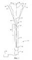
- FIG. 1is cross-sectional view of a cell necrosis apparatus of the present invention with two deployable electrodes and an deployable member at a selected cell necrosis tissue site.
- FIG. 2 ( a )illustrates a cross-sectional view of an embodiment of a cell necrosis apparatus of the present invention with a first and a second set of deployable electrodes.
- FIG. 2 ( b )illustrates the cell necrosis apparatus of FIG. 2 ( a ) positioned at a targeted cell necrosis tissue site.
- FIG. 3illustrates an embodiment of a cell necrosis apparatus of the present invention with multiple sensors coupled to electrodes.
- FIG. 4illustrates a spherical cross-section of an electrode utilized with a cell necrosis apparatus of the present invention.
- FIG. 5illustrates an elliptical cross-section of an electrode utilized with a cell necrosis apparatus of the present invention.
- FIG. 6illustrates a cross-section of an electrode utilized with a cell necrosis apparatus of the present invention with a larger cross-sectional length than its width.
- FIG. 7illustrates a cross-section of an electrode utilized with a cell necrosis apparatus of the present invention with a flat-like external surface.
- FIG. 8is a perspective view of a cell necrosis apparatus of the present invention that includes insulation sleeves positioned at exterior surfaces of the electrodes.
- FIG. 9is a perspective view of a cell necrosis apparatus of the present invention that includes multiple insulation sleeves that circumferentially insulate selected sections of the electrodes.
- FIG. 10is a perspective view of a cell necrosis apparatus of the present invention with insulation that extends along longitudinal sections of the electrodes to define adjacent longitudinal energy delivery surfaces.
- FIG. 11is a cross-sectional view of the cell necrosis apparatus of FIG. 10 taken along the lines 11 — 11 .
- FIG. 12is a perspective view of a cell necrosis apparatus of the present invention with insulation that extends along longitudinal sections of the electrodes and does not continue to distal ends of the electrodes.
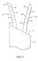
- FIG. 13is a cross-sectional view illustrating the positioning of electrodes adjacent to a selected tissue site with insulation that extends along a longitudinal surface of the electrodes and the insulation faces away from a central axis of the selected tissue site.
- FIG. 14is a cross-sectional view illustrating the positioning of electrodes at a selected tissue site with insulation that extends along a longitudinal surface of the electrodes and the insulation faces toward a central axis of the selected tissue site.
- FIG. 15is a close-up perspective view of a surface area of an electrode body at a distal end of an electrode of a cell necrosis apparatus of the present invention.
- FIG. 16is a perspective view of a cell necrosis apparatus of the present invention with spacers associated with each deployed electrode.
- FIG. 17is a cross-sectional view of a cell necrosis apparatus of the present invention illustrating a spacer, an associated electrode and insulation inside the spacer.
- FIG. 18is a cross-sectional view of an embodiment of a cell necrosis apparatus of the present invention that includes a slidable member that engages a power source to a contact coupled to the electrodes.
- FIG. 19is a cross-sectional view of the apparatus of FIG. 18 with the slidable member pulled back and disengaging the power source from the electrodes.
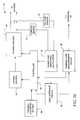
- FIG. 20is a block diagram illustrating the inclusion of a controller, electromagnetic energy source and other electronic components of the present invention.
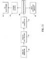
- FIG. 21is a block diagram illustrating an analog amplifier, analog multiplexer and microprocessor used with the present invention.
- a cell necrosis apparatus 10includes an introducer 12 with a distal end 14 sufficiently sharp to penetrate tissue.
- An energy delivery devicegenerally denoted as 16 , includes a first RF electrode 18 and a second RF electrode 20 .
- Electrodes 18 and 20are positionable in introducer 12 as introducer 12 advances through tissue. Electrodes 18 and 20 have tissue piercing distal ends 22 and 24 , respectively. Electrodes 18 and 20 are selectably deployed with curvature from a distal end 14 or a side port formed in a distal portion 26 of introducer 12 to a selected tissue site 28 .
- Tissue site 28can be any tissue mass and can be a tumor to be ablated.
- Electrodes 18 and 20are selectably deployed to be controllably positioned at a desired location relative to tissue site 28 that includes internal placement, external placement at a periphery of tissue site 28 and at any desired location relative to tissue site 28 .
- the selectable deployment of electrodes 18 and 20can be achieved with the amount of advancement of electrodes 18 and 20 from introducer 12 , independent advancement of electrodes 18 and 20 from introducer 12 , the lengths and/or sizes of energy delivery surfaces of electrodes 18 and 20 , the variation in materials used for electrodes 18 and 20 as well as variation of geometric configuration of electrodes 18 and 20 in their deployed states.
- Electrodes 18 and 20are in compacted positions while they are positioned in introducer 12 . As electrodes 18 and 20 are advanced from introducer 12 they move to a deployed state from their compacted configurations. Any number of electrodes can be included in energy delivery device 16 . The electrodes of energy delivery device 16 can be deployed simultaneously, in pairs, in sets and one at a time. An electrode advancement member 30 is coupled to energy delivery device 16 . Electrode advancement member 30 can be actuated by the physician by movement of a proximal end 32 relative to a longitudinal axis of introducer 12 .
- Introducer 12can be flexible. In one embodiment, introducer 12 is sufficiently flexible to pierce tissue, and move in any desired direction through tissue to tissue site 28 . In another embodiment, introducer 12 is sufficiently flexible to reverse its direction of travel and move in direction back upon itself. In one embodiment, introducer 12 is more flexible than electrodes 18 and 20 .
- energy delivery device 16When introducer 12 reaches tissue site 28 , including but not limited to a solid lesion, energy delivery device 16 is deployed preferably from distal end 14 of introducer 12 . Energy delivery device 16 can also be deployed from side ports formed in the body of introducer 12 . In the deployed state energy delivery device 16 becomes expanded from its compacted configuration in introducer 12 and is selectively positioned relative to the tissue site. Electrodes 18 and 20 can be portioned within an interior of the tissue site, at the exterior of the tissue site as well as combinations thereof. Electrodes 18 , 20 as well as third, fourth, fifth, etc. electrodes are advanceable different lengths from distal end 14 of introducer 12 . In one embodiment, the electrodes of deployed energy delivery device 16 are positioned equally distant a central axis of tissue site 28 . Volumetric cell necrosis can proceed from the interior, exterior of tissue site 28 as well as various combinations thereof with each deployed electrode of energy delivery device 16 in order to create a selectable and predictable cell necrosis.
- Electrodes 18 and 20can be made of a variety of conductive materials, both metallic and non-metallic. One suitable material is type 304 stainless steel of hypodermic quality. In some applications, all or a portion of electrodes 18 and 20 can be made of a shaped memory metal, such as NiTi, commercially available from Raychem Corporation, Menlo Park, Calif. A radiopaque marker 21 can be coated on electrodes 18 and 20 for visualization purposes.
- Electrodes 18 and 20can have different lengths that are advanced from distal end 14 of introducer 12 .
- the lengthscan be determined by the actual physical length of electrodes 18 and 20 , the length of an energy delivery surface of electrodes 18 and 20 and the length of electrodes 18 and 20 that is not covered by an insulator. Suitable lengths include but are not limited to 17.5 cm, 25.0 cm. and 30.0 cm.
- the actual lengths of electrodes 18 and 20depends on the location of tissue site 28 to be ablated, its distance from the skin, its accessibility as well as whether or not the physician chooses a laparoscopic, percutaneous or other procedure.
- a deployable member 34can be coupled to electrode advancement member 30 .
- Deployable member 34can provide a variety of different functions including but not limited to the placement of a sensor at a selected tissue site to measure/monitor temperature and/or impedance. Additionally, all or a portion of deployable member 34 can be an RF electrode operable in bi-polar or mono-polar modes. Deployable member 34 can also be a groundpad electrode.
- a sensor 36can be coupled to deployable member 34 at a distal end 38 , or at any physical location of deployable member 34 . In this manner, temperature and/or impedance is measured or monitored at a distal portion of tissue site 28 or at any position in or external to tissue site 28 .
- Deployable member 34is deployable from distal end 14 of introducer 12 with less curvature than electrodes 18 and 20 . Deployable member 34 can be deployable from distal end 14 without substantially any curvature.
- Sensor 36permits accurate measurement of temperature at tissue site 28 in order to determine, (i) the extent of cell necrosis, (ii) the amount of cell necrosis, (iii) whether or not further cell necrosis is needed and (iv) the boundary or periphery of the ablated mass. Further, sensor 36 reduces non-targeted tissue from being destroyed or ablated.
- Sensor 36is of conventional design, including but not limited to thermistors, thermocouples, resistive wires, and the like.
- a suitable thermal sensor 36includes a T type thermocouple with copper constantene, J type, E type, K type, fiber optics, resistive wires, thermocouple IR detectors, and the like. It will be appreciated that sensor 36 need not be a thermal sensor.
- Sensor 36measures temperature and/or impedance to permit monitoring and a desired level of cell necrosis to be achieved without destroying too much tissue. This reduces damage to tissue surrounding the targeted mass to be ablated.
- Sensor 36measures temperature and/or impedance to permit monitoring and a desired level of cell necrosis to be achieved without destroying too much tissue. This reduces damage to tissue surrounding the targeted mass to be ablated.
- a determination of the selected tissue mass peripherycan be made, as well as a determination of when cell necrosis is complete. If at any time sensor 36 determines that a desired cell necrosis temperature is exceeded, then an appropriate feedback signal is received at an energy source 40 coupled to energy delivery device 16 which then regulates the amount of electromagnetic energy delivered to electrodes 18 and 20 .
- Energy source 40can be an RF power supply, an ultrasound energy source, a microwave generator, a resistive heating source, a laser and the like. Microwave antenna, optical fibers, resistive heating elements and ultrasound transducers can be substituted for electrodes 18 and 20 .
- energy source 40is an RF power supply, 5 to 200 watts, preferably 5 to 100, and still more preferably 5 to 50 watts of electromagnetic energy is delivered from energy source 40 to the electrodes of energy delivery device 16 without impeding out the electrodes.
- Electrodes 18 and 20are electromagnetically coupled to energy source 40 .
- the couplingcan be direct from energy source 40 to each electrode 18 and 20 respectively, or indirect by using a collet, sleeve and the like which couples one or more electrodes to energy source 40 .
- Apparatus 10includes a first set 42 of RF electrodes and a second set 44 of RF electrodes.
- First and second sets 42 and 44can include one, two, three, four, five, etc, number of RF electrodes.
- first set 42includes electrodes 46 and 48
- second set 44includes electrodes 50 and 52 .
- Electrodes 46 , 48 , 50 and 52have tissue piercing distal ends, are positionable in introducer 12 in compacted states, and advanceable to deployed states from distal end 14 with curvature from introducer 12 .
- First set 42is deployable a greater distance from distal end 14 than second set 44 .
- First and second sets 42 and 44are coupled to electrode advancement member 30 and can be simultaneously or individually deployed from distal end 14 .
- deployable member 34is optionally coupled to first set 42 , second set 44 and/or electrode advancement member 30 .
- deployable member 34can be coupled to a sensor 36 and all or a portion of deployable member 34 may be an RF electrode.
- FIG. 2 ( b )illustrates the use of multiple sensors 36 .
- Sensors 36can be coupled to all or some of electrodes 46 , 48 , 50 and/or 52 at different positions of the electrodes.
- sensorsare positioned at distal ends of electrodes 46 through 52 , at positions that are adjacent to distal end 14 of introducer 12 , and at sites that are somewhere intermediate between the distal and proximal portions of deployed lengths of the electrodes.
- Deployable member 34can include sensors at distal and proximal portions of its deployed length in tissue site 28 . The placement of sensors 36 at different locations provides a measurement of temperature and/or impedance, and a determination of the level of cell necrosis, created at tissue site 28 .
- electrodes 18 , 20 , 46 , 48 , 50 and 52can each be coupled to one or more sensors 36 .
- Sensors 36can be at exterior surfaces of electrodes 18 at their distal ends, intermediate sections as well as adjacent to distal end 14 of introducer 12 .
- Some or all of electrodes 18 and deployable member 34may have a hollow lumen by which a variety of different fluidic medium can be introduced from proximal to distal ends. Suitable fluidic media include but are not limited to electrolytic solutions, chemotherapeutic agents, drugs, medicaments, gene therapy agents, contrast agents and the like.
- Electrode 18can have a variety of different geometric cross-sections. Electrodes 18 can be made of conductive solid or hollow straight wires of various shapes such as round, flat, triangular, rectangular, hexagonal, elliptical and the like.
- FIGS. 4 and 5illustrate circular and elliptical cross-sections. In FIG. 6, the cross-section has a greater length “L” than a width of “W”. In FIG. 7, the cross-sectional is elongated. In various embodiments, the cross-sectional has a greater length than a width in order to enhance ultrasonic viewability.
- two electrodes 18include insulation 54 .
- insulation 54is a sleeve that can be fixed or adjustable.
- the active area of electrodes 18is non-insulated and provides an energy delivery surface 56 .
- insulation 54is formed at the exterior of electrodes 18 in circumferential patterns, leaving a plurality of energy delivery surfaces 56 .
- insulation 54extends along a longitudinal exterior surface of electrodes 18 .
- Insulation 54can extend along a selected distance along a longitudinal length of electrodes 18 and around a selectable portion of a circumference of electrodes 18 .
- sections of electrodes 18can have insulation 54 along selected longitudinal lengths of electrodes 18 as well as completely surround one or more circumferential sections of electrodes 18 .
- Insulation 54 positioned at the exterior of electrodes 18can be varied to define any desired shape, size and geometric energy delivery surface 56 .
- insulation 54is disposed on only one section of a deployed length of electrodes 18 .
- Energy delivery surfaces 56are at distal portions of electrodes 18 as well as on longitudinal surfaces adjacent to insulation 54 .
- insulation 54extends along a longitudinal length of electrodes 18 can face toward a central axis 58 of tissue site 28 and energy delivery surface 56 faces towards in a direction toward the central axis 58 .
- insulation 54extends along a longitudinal length of electrodes 18 and faces away from central axis 58 with energy delivery surface 56 facing away from central axis 58 .
- three electrodes 18are positioned inside or outside of a periphery of tissue site 28 . It will be appreciated that any number of electrodes 18 can be deployed with and without insulation to created a selectable cell necrosis pattern.
- Electrodes 18are selectably deployable from introducer 12 with curvature to create any desired geometric area of cell necrosis.
- the selectable deploymentis achieved by having electrodes 18 with, (i) different advancement lengths from introducer 12 , (ii) different deployed geometric configurations, (iii) variations in cross-sectional geometries, (iv) selectable insulation provided at each and/or all of the deployed electrodes 18 , or (v) the use of adjustable insulation.
- Deployed electrodes 18can create a variety of different geometric cell necrosis zones including but not limited to spherical, semi-spherical, spheroid, triangular, semi-triangular, square, semi-square, rectangular, semi-rectangular, conical, semi-conical, quadrilateral, semi-quadrilateral, semi-quadrilateral, rhomboidal, semi-rhomboidal, trapezoidal, semi-trapezoidal, combinations of the preceding, geometries with non-planar sections or sides, free-form and the like.
- the ultrasonic visibility of electrodes 18 throughis enhanced by creating a larger electrode distal end surface area 60 .
- Surface area 60is the amount of the electrode body that is at the distal end of electrodes 18 .
- the distal end of electrode 18has at cut angle of at least 25°, and in another embodiment the cut angle is at least 30°. This creates a larger surface area 60 .
- the distal end of deployable member 34can also have these cut angles.
- each or selected electrodes 18 and deployable member 34can have an associated spacer 62 .
- Spacers 62are advanceable from distal end 14 of introducer 12 and can be coupled to advancement member 30 .
- Spacers 62create a physical spacing that separates the deployed electrodes 18 from each other. The spacing created by spacers 62 also forms an area in tissue site 28 where there is reduced or very little cell necrosis.
- an insulation 64Positioned within spacers 62 is an insulation 64 that electrically and electromagnetically isolates electrodes 18 from spacers 62 .
- apparatus 10can include a slidable member 66 that provides an electrical connection between energy delivery device 16 and energy source 40 .
- Slidable member 66can be advancement member 30 or a handpiece.
- slidable member 66has one or two electrical contact pads 68 which can be resistor strips. When the slidable member is moved in a distal direction relative to distal end 14 of introducer 12 resistor strips 68 become engaged with a contact 70 (FIG. 18 ). Contact 70 is coupled to energy delivery device 16 . When resistor strips 68 are engaged with contact 70 , power and energy is delivered from the energy source to electrodes 18 .
- Slidable member 66is then moved in a distal direction and resistor strips become un-engaged with contact 70 and the delivery of power from energy source 40 is disrupted (FIG. 19 ).
- the employment of slidable member 66provides a convenient energy delivery device 16 on and off mechanism at the hand of the physician.
- Resistor strips 68can be used as sensors to recognize a variable setting of one or all of electrodes 18 of energy delivery device 16 . Resistor strips 68 can be used to measure resistance at a setting so that a change in the resistance value can be measured as slidable member 66 is moved and a corresponding change in the energy delivery surface corresponding to the electrodes 18 . The resistance value can be correlated to determine an optimal power in delivering energy from energy source 40 . Gap sensors, including but not limited to lasers and ultrasound, can be used to determine the variable setting.
- a feedback control system 72is connected to energy source 40 , sensors 36 and energy delivery device 16 .
- Feedback control system 72receives temperature or impedance data from sensors 36 and the amount of electromagnetic energy received by energy delivery device 16 is modified from an initial setting of cell necrosis energy output, cell necrosis time, temperature, and current density (the “Four Parameters”).
- Feedback control system 72can automatically change any of the Four Parameters.
- Feedback control system 72can detect impedance or temperature and change any of the Four Parameters.
- Feedback control system 72can include a multiplexer to multiplex different electrodes 18 and a temperature detection circuit that provides a control signal representative of temperature or impedance detected at one or more sensors 36 .
- a microprocessorcan be connected to the temperature control circuit.
- the user of apparatus 10can input an impedance value which corresponds to a setting position located at apparatus 10 . Based on this value, along with measured impedance values, feedback control system 72 determines an optimal power and time need in the delivery of RF energy. Temperature is also sensed for monitoring and feedback purposes. Temperature can be maintained to a certain level by having feedback control system 72 adjust the power output automatically to maintain that level.
- feedback control system 72determines an optimal power and time for a baseline setting. Ablation volumes or lesions are formed at the baseline first. Larger lesions can be obtained by extending the time of ablation after a center core is formed at the baseline. A completion of lesion creation can be checked by advancing energy delivery device 16 from distal end 14 of introducer 12 to a desired lesion size and by monitoring the temperature at the periphery of the lesion.
- feedback control system 72is programmed so the delivery of energy to energy delivery device 16 is paused at certain intervals at which time temperature is measured. By comparing measured temperatures to desired temperatures feedback control system 72 can terminate or continue the delivery of power to electrodes 18 for an appropriate length of time.
- a control signalis generated by controller 82 that is proportional to the difference between an actual measured value, and a desired value.
- the control signalis used by power circuits 84 to adjust the power output in an appropriate amount in order to maintain the desired power delivered at energy delivery device 16 .
- temperatures detected at sensors 36provide feedback for determining the extent of cell necrosis, and when a completed cell necrosis has reached the physical location of sensors 36 .
- the actual temperaturesare measured at temperature measurement device 86 and the temperatures are displayed at user interface and display 80 .
- a control signalis generated by controller 82 that is proportional to the difference between an actual measured temperature, and a desired temperature.
- the control signalis used by power circuits 84 to adjust the power output in an appropriate amount in order to maintain the desired temperature delivered at the respective sensor 36 .
- a multiplexercan be included to measure current, voltage and temperature, at the numerous sensors 36 , and energy is delivered to energy delivery device 16 .
- a variable electrode setting 88is coupled to controller 82 .
- Controller 82can be a digital or analog controller, or a computer with software.
- controller 82is a computer it can include a CPU coupled through a system bus.
- On this systemcan be a keyboard, a disk drive, or other non-volatile memory systems, a display, and other peripherals, as are known in the art.
- Also coupled to the busare a program memory and a data memory.
- User interface and display 80includes operator controls and a display.
- Controller 82can be coupled to imaging systems, including but not limited to ultrasound, CT scanners, X-ray, MRI, mammographic X-ray and the like. Further, direct visualization and tactile imaging can be utilized.
- the output of current sensor 74 and voltage sensor 76is used by controller 82 to maintain a selected power level at energy delivery device 16 .
- the amount of RF energy deliveredcontrols the amount of power.
- a profile of power deliveredcan be incorporated in controller 82 , and a preset amount of energy to be delivered can also be profiled.
- Circuitry, software and feedback to controller 82result in process control, and the maintenance of the selected power, and are used to change, (i) the selected power, including RF, microwave, laser and the like, (ii) the duty cycle (on-off and wattage), (iii) bi-polar or mono-polar energy delivery and (iv) infusion medium delivery, including flow rate and pressure.
- process variablesare controlled and varied, while maintaining the desired delivery of power independent of changes in voltage or current, based on temperatures monitored at sensors 36 .
- Analog amplifier 90can be a conventional differential amplifier circuit for use with sensors 36 .
- the output of analog amplifier 90is sequentially connected by an analog multiplexer 46 to the input of A/D converter 92 .
- the output of analog amplifier 90is a voltage which represents the respective sensed temperatures.
- Digitized amplifier output voltagesare supplied by A/D converter 92 to a microprocessor 96 .
- Microprocessor 96may be Model No. 68HCII available from Motorola. However, it will be appreciated that any suitable microprocessor or general purpose digital or analog computer can be used to calculate impedance or temperature.
- Microprocessor 96sequentially receives and stores digital representations of impedance and temperature. Each digital value received by microprocessor 96 corresponds to different temperatures and impedances.
- Calculated power and impedance valuescan be indicated on user interface and display 80 .
- calculated impedance and power valuescan be compared by microprocessor 96 with power and impedance limits. When the values exceed predetermined power or impedance values, a warning can be given on user interface and display 80 , and additionally, the delivery of RF energy can be reduced, modified or interrupted.
- a control signal from microprocessor 96can modify the power level supplied by energy source 40 .
Landscapes
- Health & Medical Sciences (AREA)
- Life Sciences & Earth Sciences (AREA)
- Surgery (AREA)
- Engineering & Computer Science (AREA)
- Animal Behavior & Ethology (AREA)
- Public Health (AREA)
- Nuclear Medicine, Radiotherapy & Molecular Imaging (AREA)
- Veterinary Medicine (AREA)
- Biomedical Technology (AREA)
- General Health & Medical Sciences (AREA)
- Medical Informatics (AREA)
- Molecular Biology (AREA)
- Physics & Mathematics (AREA)
- Heart & Thoracic Surgery (AREA)
- Otolaryngology (AREA)
- Electromagnetism (AREA)
- Radiology & Medical Imaging (AREA)
- Plasma & Fusion (AREA)
- Surgical Instruments (AREA)
Abstract
Description
Claims (29)
Priority Applications (1)
| Application Number | Priority Date | Filing Date | Title |
|---|---|---|---|
| US09/758,326US6551311B2 (en) | 1995-08-15 | 2001-01-10 | Cell necrosis apparatus and method |
Applications Claiming Priority (6)
| Application Number | Priority Date | Filing Date | Title |
|---|---|---|---|
| US08/515,379US5683384A (en) | 1993-11-08 | 1995-08-15 | Multiple antenna ablation apparatus |
| US08/963,239US6958062B1 (en) | 1993-11-08 | 1997-11-03 | Multiple antenna ablation apparatus and method |
| US09/020,182US6132425A (en) | 1995-08-15 | 1998-02-06 | Cell necrosis apparatus |
| US09/047,845US5980517A (en) | 1995-08-15 | 1998-03-25 | Cell necrosis apparatus |
| US09/148,571US6235023B1 (en) | 1995-08-15 | 1998-09-04 | Cell necrosis apparatus |
| US09/758,326US6551311B2 (en) | 1995-08-15 | 2001-01-10 | Cell necrosis apparatus and method |
Related Parent Applications (1)
| Application Number | Title | Priority Date | Filing Date |
|---|---|---|---|
| US09/148,571ContinuationUS6235023B1 (en) | 1995-08-15 | 1998-09-04 | Cell necrosis apparatus |
Publications (2)
| Publication Number | Publication Date |
|---|---|
| US20010001819A1 US20010001819A1 (en) | 2001-05-24 |
| US6551311B2true US6551311B2 (en) | 2003-04-22 |
Family
ID=22526354
Family Applications (2)
| Application Number | Title | Priority Date | Filing Date |
|---|---|---|---|
| US09/148,571Expired - LifetimeUS6235023B1 (en) | 1995-08-15 | 1998-09-04 | Cell necrosis apparatus |
| US09/758,326Expired - Fee RelatedUS6551311B2 (en) | 1995-08-15 | 2001-01-10 | Cell necrosis apparatus and method |
Family Applications Before (1)
| Application Number | Title | Priority Date | Filing Date |
|---|---|---|---|
| US09/148,571Expired - LifetimeUS6235023B1 (en) | 1995-08-15 | 1998-09-04 | Cell necrosis apparatus |
Country Status (6)
| Country | Link |
|---|---|
| US (2) | US6235023B1 (en) |
| EP (1) | EP1109505A1 (en) |
| JP (1) | JP2002524130A (en) |
| AU (1) | AU6024799A (en) |
| TW (1) | TW402498B (en) |
| WO (1) | WO2000013603A1 (en) |
Cited By (27)
| Publication number | Priority date | Publication date | Assignee | Title |
|---|---|---|---|---|
| US20030157178A1 (en)* | 2001-11-14 | 2003-08-21 | Guohua Chen | Injectable depot composition |
| US20030212394A1 (en)* | 2001-05-10 | 2003-11-13 | Rob Pearson | Tissue ablation apparatus and method |
| US20040077951A1 (en)* | 2002-07-05 | 2004-04-22 | Wei-Chiang Lin | Apparatus and methods of detection of radiation injury using optical spectroscopy |
| US20040176755A1 (en)* | 2001-12-18 | 2004-09-09 | Scimed Life Systems, Inc., A Minnesota Corporation | Cryo-temperature monitoring |
| US20050015081A1 (en)* | 2003-07-18 | 2005-01-20 | Roman Turovskiy | Devices and methods for cooling microwave antennas |
| US20050113660A1 (en)* | 2002-08-30 | 2005-05-26 | Biosense Webster, Inc. | Catheter and method for mapping purkinje fibers |
| US20050148837A1 (en)* | 2001-12-31 | 2005-07-07 | Fuimaono Kristine B. | Catheter having multiple spines each having electrical mapping and location sensing capabilities |
| US20050165390A1 (en)* | 2002-02-11 | 2005-07-28 | Aldo Mauti | Apparatus for electrosurgery |
| US20050190982A1 (en)* | 2003-11-28 | 2005-09-01 | Matsushita Electric Industrial Co., Ltd. | Image reducing device and image reducing method |
| US20060095029A1 (en)* | 2004-10-28 | 2006-05-04 | Scimed Life Systems, Inc. | Ablation probe with flared electrodes |
| US20060173359A1 (en)* | 2002-09-30 | 2006-08-03 | Lin Wei C | Optical apparatus for guided liver tumor treatment and methods |
| US7318824B2 (en) | 2001-11-02 | 2008-01-15 | Vivant Medical, Inc. | High-strength microwave antenna assemblies |
| US20090292211A1 (en)* | 2002-07-05 | 2009-11-26 | Vanderbilt University | Methods and Apparatus for Optical Spectroscopic Detection of Cell and Tissue Death |
| US20100256624A1 (en)* | 2009-04-01 | 2010-10-07 | Vivant Medical, Inc. | Microwave Ablation System with User-Controlled Ablation Size and Method of Use |
| US8480666B2 (en) | 2007-01-31 | 2013-07-09 | Covidien Lp | Thermal feedback systems and methods of using the same |
| US8894641B2 (en) | 2009-10-27 | 2014-11-25 | Covidien Lp | System and method for monitoring ablation size |
| US9681916B2 (en) | 2012-01-06 | 2017-06-20 | Covidien Lp | System and method for treating tissue using an expandable antenna |
| US9693823B2 (en) | 2012-01-06 | 2017-07-04 | Covidien Lp | System and method for treating tissue using an expandable antenna |
| US9949794B2 (en) | 2008-03-27 | 2018-04-24 | Covidien Lp | Microwave ablation devices including expandable antennas and methods of use |
| US10076383B2 (en) | 2012-01-25 | 2018-09-18 | Covidien Lp | Electrosurgical device having a multiplexer |
| US10159526B2 (en) | 2013-02-21 | 2018-12-25 | Stryker Corporation | Tissue ablation cannula assembly |
| US10531907B2 (en) | 2015-11-20 | 2020-01-14 | Covidien Lp | Devices, systems, and methods for treating ulcerative colitis and other inflammatory bowel diseases |
| US10716618B2 (en) | 2010-05-21 | 2020-07-21 | Stratus Medical, LLC | Systems and methods for tissue ablation |
| US10736688B2 (en) | 2009-11-05 | 2020-08-11 | Stratus Medical, LLC | Methods and systems for spinal radio frequency neurotomy |
| US11039879B2 (en) | 2015-10-20 | 2021-06-22 | Gyrus Acmi, Inc. | Ablation device |
| US11439456B2 (en)* | 2017-03-15 | 2022-09-13 | Olympus Corporation | Energy source apparatus |
| US11478296B2 (en) | 2014-03-28 | 2022-10-25 | Gyrus Acmi, Inc. | System and method for predictable deployment of a medical device |
Families Citing this family (124)
| Publication number | Priority date | Publication date | Assignee | Title |
|---|---|---|---|---|
| US6603988B2 (en) | 2001-04-13 | 2003-08-05 | Kelsey, Inc. | Apparatus and method for delivering ablative laser energy and determining the volume of tumor mass destroyed |
| US6805130B2 (en)* | 1995-11-22 | 2004-10-19 | Arthrocare Corporation | Methods for electrosurgical tendon vascularization |
| US7276063B2 (en)* | 1998-08-11 | 2007-10-02 | Arthrocare Corporation | Instrument for electrosurgical tissue treatment |
| US6306132B1 (en)* | 1999-06-17 | 2001-10-23 | Vivant Medical | Modular biopsy and microwave ablation needle delivery apparatus adapted to in situ assembly and method of use |
| ITMI991608A1 (en)* | 1999-07-21 | 2001-01-21 | Thermo Med 2000 Kft | ELECTROSURGICAL PROBE FOR TREATMENT OF TUMORS BY RADIOFREQUENCY |
| US6770070B1 (en)* | 2000-03-17 | 2004-08-03 | Rita Medical Systems, Inc. | Lung treatment apparatus and method |
| JP4723156B2 (en)* | 2000-03-31 | 2011-07-13 | アンジオ ダイナミクス インコーポレイテッド | Tissue biopsy and treatment equipment |
| JP2003528687A (en)* | 2000-04-04 | 2003-09-30 | エヌ ブイ サーモコア メディカル システムズ エス.エイ. | Blood vessel temperature measuring device and blood vessel temperature measuring process |
| US7090645B2 (en) | 2000-04-04 | 2006-08-15 | Nv Thermocore Medical Systems Sa | Biased vascular temperature measuring device |
| US6712771B2 (en) | 2000-06-16 | 2004-03-30 | Accumed Systems, Inc. | Temperature sensing catheter |
| US20040034303A1 (en)* | 2000-06-16 | 2004-02-19 | Korotko Joseph R. | Blood-flow-occluding, temperature-sensing catheters and methods of use |
| US6638277B2 (en)* | 2000-07-06 | 2003-10-28 | Scimed Life Systems, Inc. | Tumor ablation needle with independently activated and independently traversing tines |
| JP2004520865A (en)* | 2000-07-25 | 2004-07-15 | リタ メディカル システムズ インコーポレイテッド | Apparatus for tumor detection and treatment using localized impedance measurements |
| US6840935B2 (en)* | 2000-08-09 | 2005-01-11 | Bekl Corporation | Gynecological ablation procedure and system using an ablation needle |
| US7008421B2 (en)* | 2002-08-21 | 2006-03-07 | Resect Medical, Inc. | Apparatus and method for tissue resection |
| US6994706B2 (en) | 2001-08-13 | 2006-02-07 | Minnesota Medical Physics, Llc | Apparatus and method for treatment of benign prostatic hyperplasia |
| JP4450622B2 (en)* | 2001-09-28 | 2010-04-14 | アンジオ ダイナミクス インコーポレイテッド | Impedance-controlled tissue peeling device and method |
| US20030093007A1 (en)* | 2001-10-17 | 2003-05-15 | The Government Of The U.S.A., As Represented By The Secretary, Department Of Health And Human Serv | Biopsy apparatus with radio frequency cauterization and methods for its use |
| US7128739B2 (en)* | 2001-11-02 | 2006-10-31 | Vivant Medical, Inc. | High-strength microwave antenna assemblies and methods of use |
| US6752767B2 (en) | 2002-04-16 | 2004-06-22 | Vivant Medical, Inc. | Localization element with energized tip |
| US7197363B2 (en) | 2002-04-16 | 2007-03-27 | Vivant Medical, Inc. | Microwave antenna having a curved configuration |
| ITBS20020042A1 (en)* | 2002-04-23 | 2003-10-23 | Fogazzi Di Venturelli A E C S | NEEDLE ELECTRODE PERFECTED FOR A TREATMENT OF TUMORS BY RADIOFREQUENCY-INDUCED HYPERTHERMIA |
| US7223264B2 (en)* | 2002-08-21 | 2007-05-29 | Resect Medical, Inc. | Thermal coagulation of tissue during tissue resection |
| US7027851B2 (en)* | 2002-10-30 | 2006-04-11 | Biosense Webster, Inc. | Multi-tip steerable catheter |
| US7003342B2 (en)* | 2003-06-02 | 2006-02-21 | Biosense Webster, Inc. | Catheter and method for mapping a pulmonary vein |
| US7818048B2 (en) | 2003-06-02 | 2010-10-19 | Biosense Webster, Inc. | Catheter and method for mapping a pulmonary vein |
| CA2532815A1 (en)* | 2003-07-11 | 2005-01-27 | Steven A. Daniel | Thermal ablation of biological tissue |
| US20050080410A1 (en)* | 2003-10-14 | 2005-04-14 | Scimed Life Systems, Inc. | Liquid infusion apparatus for radiofrequency tissue ablation |
| US7282051B2 (en)* | 2004-02-04 | 2007-10-16 | Boston Scientific Scimed, Inc. | Ablation probe for delivering fluid through porous structure |
| CN2722849Y (en)* | 2004-03-12 | 2005-09-07 | 王洪奎 | Radio frequency melting incisal mergin electrode |
| EP1853188B1 (en)* | 2005-01-18 | 2020-03-11 | S.D.M.H. Pty. Ltd. | Device for thermal ablation of biological tissue using spherical ablation patterns |
| GB0502384D0 (en)* | 2005-02-04 | 2005-03-16 | Instrumedical Ltd | Electro-surgical needle apparatus |
| US7601149B2 (en)* | 2005-03-07 | 2009-10-13 | Boston Scientific Scimed, Inc. | Apparatus for switching nominal and attenuated power between ablation probes |
| US8765116B2 (en)* | 2005-03-24 | 2014-07-01 | Medifocus, Inc. | Apparatus and method for pre-conditioning/fixation and treatment of disease with heat activation/release with thermoactivated drugs and gene products |
| US7799019B2 (en) | 2005-05-10 | 2010-09-21 | Vivant Medical, Inc. | Reinforced high strength microwave antenna |
| US7794458B2 (en)* | 2005-07-22 | 2010-09-14 | Boston Scientific Scimed, Inc. | Bipolar radio frequency ablation device with retractable insulator |
| JP5094132B2 (en)* | 2006-04-07 | 2012-12-12 | 株式会社デージーエス・コンピュータ | RF wave irradiation element for subject lesion |
| US20080221650A1 (en)* | 2006-08-04 | 2008-09-11 | Turner Paul F | Microwave applicator with adjustable heating length |
| US20080033422A1 (en)* | 2006-08-04 | 2008-02-07 | Turner Paul F | Microwave applicator with margin temperature sensing element |
| EP2068739A4 (en)* | 2006-09-14 | 2013-01-23 | Lazure Technologies Llc | Device and method for destruction of cancer cells |
| WO2008039188A1 (en)* | 2006-09-27 | 2008-04-03 | Boston Scientific Corporation | Method of treating cancer comprising introduction of heat and delivery of liposome containing an active agent or thermo-activated drug, gene or virus to tissue |
| US8068921B2 (en) | 2006-09-29 | 2011-11-29 | Vivant Medical, Inc. | Microwave antenna assembly and method of using the same |
| US8979829B2 (en) | 2007-02-05 | 2015-03-17 | Novian Health, Inc. | Interstitial laser therapy kits |
| US8092507B2 (en) | 2007-02-05 | 2012-01-10 | Novian Health, Inc. | Interstitial energy treatment probe holders |
| JP5216994B2 (en)* | 2007-03-27 | 2013-06-19 | 国立大学法人滋賀医科大学 | Microwave surgical device |
| US7998139B2 (en) | 2007-04-25 | 2011-08-16 | Vivant Medical, Inc. | Cooled helical antenna for microwave ablation |
| US8216221B2 (en)* | 2007-05-21 | 2012-07-10 | Estech, Inc. | Cardiac ablation systems and methods |
| US8353901B2 (en) | 2007-05-22 | 2013-01-15 | Vivant Medical, Inc. | Energy delivery conduits for use with electrosurgical devices |
| US9023024B2 (en) | 2007-06-20 | 2015-05-05 | Covidien Lp | Reflective power monitoring for microwave applications |
| US20090005766A1 (en)* | 2007-06-28 | 2009-01-01 | Joseph Brannan | Broadband microwave applicator |
| US20090076412A1 (en)* | 2007-09-13 | 2009-03-19 | Boston Scientific Scimed, Inc. | Apparatus and Methods for Obtaining a Sample of Tissue |
| US20090076500A1 (en)* | 2007-09-14 | 2009-03-19 | Lazure Technologies, Llc | Multi-tine probe and treatment by activation of opposing tines |
| US8651146B2 (en) | 2007-09-28 | 2014-02-18 | Covidien Lp | Cable stand-off |
| US8241276B2 (en)* | 2007-11-14 | 2012-08-14 | Halt Medical Inc. | RF ablation device with jam-preventing electrical coupling member |
| US8292880B2 (en) | 2007-11-27 | 2012-10-23 | Vivant Medical, Inc. | Targeted cooling of deployable microwave antenna |
| US10117707B2 (en) | 2008-04-29 | 2018-11-06 | Virginia Tech Intellectual Properties, Inc. | System and method for estimating tissue heating of a target ablation zone for electrical-energy based therapies |
| US10238447B2 (en) | 2008-04-29 | 2019-03-26 | Virginia Tech Intellectual Properties, Inc. | System and method for ablating a tissue site by electroporation with real-time monitoring of treatment progress |
| US9598691B2 (en) | 2008-04-29 | 2017-03-21 | Virginia Tech Intellectual Properties, Inc. | Irreversible electroporation to create tissue scaffolds |
| US10272178B2 (en) | 2008-04-29 | 2019-04-30 | Virginia Tech Intellectual Properties Inc. | Methods for blood-brain barrier disruption using electrical energy |
| US10245098B2 (en) | 2008-04-29 | 2019-04-02 | Virginia Tech Intellectual Properties, Inc. | Acute blood-brain barrier disruption using electrical energy based therapy |
| US9867652B2 (en) | 2008-04-29 | 2018-01-16 | Virginia Tech Intellectual Properties, Inc. | Irreversible electroporation using tissue vasculature to treat aberrant cell masses or create tissue scaffolds |
| US9198733B2 (en) | 2008-04-29 | 2015-12-01 | Virginia Tech Intellectual Properties, Inc. | Treatment planning for electroporation-based therapies |
| US9283051B2 (en) | 2008-04-29 | 2016-03-15 | Virginia Tech Intellectual Properties, Inc. | System and method for estimating a treatment volume for administering electrical-energy based therapies |
| US11272979B2 (en) | 2008-04-29 | 2022-03-15 | Virginia Tech Intellectual Properties, Inc. | System and method for estimating tissue heating of a target ablation zone for electrical-energy based therapies |
| US8992517B2 (en) | 2008-04-29 | 2015-03-31 | Virginia Tech Intellectual Properties Inc. | Irreversible electroporation to treat aberrant cell masses |
| US11254926B2 (en) | 2008-04-29 | 2022-02-22 | Virginia Tech Intellectual Properties, Inc. | Devices and methods for high frequency electroporation |
| US10702326B2 (en) | 2011-07-15 | 2020-07-07 | Virginia Tech Intellectual Properties, Inc. | Device and method for electroporation based treatment of stenosis of a tubular body part |
| US8747400B2 (en)* | 2008-08-13 | 2014-06-10 | Arthrocare Corporation | Systems and methods for screen electrode securement |
| US8355799B2 (en) | 2008-12-12 | 2013-01-15 | Arthrocare Corporation | Systems and methods for limiting joint temperature |
| US8632534B2 (en) | 2009-04-03 | 2014-01-21 | Angiodynamics, Inc. | Irreversible electroporation (IRE) for congestive obstructive pulmonary disease (COPD) |
| US11638603B2 (en) | 2009-04-09 | 2023-05-02 | Virginia Tech Intellectual Properties, Inc. | Selective modulation of intracellular effects of cells using pulsed electric fields |
| US11382681B2 (en) | 2009-04-09 | 2022-07-12 | Virginia Tech Intellectual Properties, Inc. | Device and methods for delivery of high frequency electrical pulses for non-thermal ablation |
| GB0906572D0 (en)* | 2009-04-16 | 2009-05-20 | Gyrus Medical Ltd | A surgical instrument |
| WO2010138919A2 (en) | 2009-05-28 | 2010-12-02 | Angiodynamics, Inc. | System and method for synchronizing energy delivery to the cardiac rhythm |
| US9895189B2 (en) | 2009-06-19 | 2018-02-20 | Angiodynamics, Inc. | Methods of sterilization and treating infection using irreversible electroporation |
| WO2011022674A2 (en)* | 2009-08-20 | 2011-02-24 | Angiodynamics, Inc. | Multi-electrode energy delivery device and method of using the same |
| US8323279B2 (en) | 2009-09-25 | 2012-12-04 | Arthocare Corporation | System, method and apparatus for electrosurgical instrument with movable fluid delivery sheath |
| US8317786B2 (en) | 2009-09-25 | 2012-11-27 | AthroCare Corporation | System, method and apparatus for electrosurgical instrument with movable suction sheath |
| US9993294B2 (en)* | 2009-11-17 | 2018-06-12 | Perseon Corporation | Microwave coagulation applicator and system with fluid injection |
| US20110125148A1 (en)* | 2009-11-17 | 2011-05-26 | Turner Paul F | Multiple Frequency Energy Supply and Coagulation System |
| US8551083B2 (en) | 2009-11-17 | 2013-10-08 | Bsd Medical Corporation | Microwave coagulation applicator and system |
| US8414570B2 (en)* | 2009-11-17 | 2013-04-09 | Bsd Medical Corporation | Microwave coagulation applicator and system |
| WO2011103096A2 (en)* | 2010-02-16 | 2011-08-25 | Angiodynamics, Inc. | Ablation device with guide sleeves |
| US8568404B2 (en)* | 2010-02-19 | 2013-10-29 | Covidien Lp | Bipolar electrode probe for ablation monitoring |
| US8696659B2 (en) | 2010-04-30 | 2014-04-15 | Arthrocare Corporation | Electrosurgical system and method having enhanced temperature measurement |
| EP2627274B1 (en) | 2010-10-13 | 2022-12-14 | AngioDynamics, Inc. | System for electrically ablating tissue of a patient |
| WO2012088149A2 (en) | 2010-12-20 | 2012-06-28 | Virginia Tech Intellectual Properties, Inc. | High-frequency electroporation for cancer therapy |
| ES2864589T3 (en) | 2011-04-12 | 2021-10-14 | Thermedical Inc | Devices for conformal therapy in fluid-enhanced ablation |
| US9078665B2 (en) | 2011-09-28 | 2015-07-14 | Angiodynamics, Inc. | Multiple treatment zone ablation probe |
| AU2012323882A1 (en) | 2011-10-15 | 2014-05-15 | Diros Technology Inc. | Method and apparatus for precisely controlling the size and shape of radiofrequency ablations |
| US9414881B2 (en) | 2012-02-08 | 2016-08-16 | Angiodynamics, Inc. | System and method for increasing a target zone for electrical ablation |
| US9314299B2 (en) | 2012-03-21 | 2016-04-19 | Biosense Webster (Israel) Ltd. | Flower catheter for mapping and ablating veinous and other tubular locations |
| US9144459B2 (en) | 2012-07-19 | 2015-09-29 | Cook Medical Technologies Llc | Endoscopic ultrasound ablation needle |
| US9364277B2 (en) | 2012-12-13 | 2016-06-14 | Cook Medical Technologies Llc | RF energy controller and method for electrosurgical medical devices |
| US9204921B2 (en) | 2012-12-13 | 2015-12-08 | Cook Medical Technologies Llc | RF energy controller and method for electrosurgical medical devices |
| USD733873S1 (en) | 2013-05-07 | 2015-07-07 | Novian Health Inc. | Probe holder |
| WO2015175570A1 (en) | 2014-05-12 | 2015-11-19 | Virginia Tech Intellectual Properties, Inc. | Selective modulation of intracellular effects of cells using pulsed electric fields |
| US9649148B2 (en) | 2014-07-24 | 2017-05-16 | Arthrocare Corporation | Electrosurgical system and method having enhanced arc prevention |
| US9597142B2 (en) | 2014-07-24 | 2017-03-21 | Arthrocare Corporation | Method and system related to electrosurgical procedures |
| EP3174485B1 (en) | 2014-07-28 | 2021-10-27 | Boston Scientific Scimed, Inc. | Multiple lead electrode probe for controlled tissue ablation |
| US12114911B2 (en) | 2014-08-28 | 2024-10-15 | Angiodynamics, Inc. | System and method for ablating a tissue site by electroporation with real-time pulse monitoring |
| JP6725178B2 (en) | 2014-11-19 | 2020-07-15 | エピックス セラピューティクス,インコーポレイテッド | Ablation apparatus, systems and methods using high resolution electrode assemblies |
| WO2016081611A1 (en) | 2014-11-19 | 2016-05-26 | Advanced Cardiac Therapeutics, Inc. | High-resolution mapping of tissue with pacing |
| JP6825789B2 (en) | 2014-11-19 | 2021-02-03 | エピックス セラピューティクス,インコーポレイテッド | Systems and methods for high resolution mapping of tissues |
| US10694972B2 (en) | 2014-12-15 | 2020-06-30 | Virginia Tech Intellectual Properties, Inc. | Devices, systems, and methods for real-time monitoring of electrophysical effects during tissue treatment |
| EP3254725B8 (en)* | 2015-02-03 | 2020-03-25 | VIOL Co. Ltd. | Apparatus for treating blood vessels in skin |
| US9636164B2 (en) | 2015-03-25 | 2017-05-02 | Advanced Cardiac Therapeutics, Inc. | Contact sensing systems and methods |
| US20170143405A1 (en)* | 2015-11-20 | 2017-05-25 | Covidien Lp | Apparatuses, systems and methods for treating ulcerative colitis and other inflammatory bowel diseases |
| WO2017160808A1 (en) | 2016-03-15 | 2017-09-21 | Advanced Cardiac Therapeutics, Inc. | Improved devices, systems and methods for irrigated ablation |
| US20190183563A1 (en)* | 2016-06-14 | 2019-06-20 | The Standard Co., Ltd. | Therapeutic device employing endoscope-interworking electrode |
| WO2017217760A1 (en)* | 2016-06-14 | 2017-12-21 | (주)더스탠다드 | Therapeutic device employing endoscope-interworking electrode |
| US9743984B1 (en) | 2016-08-11 | 2017-08-29 | Thermedical, Inc. | Devices and methods for delivering fluid to tissue during ablation therapy |
| US10905492B2 (en) | 2016-11-17 | 2021-02-02 | Angiodynamics, Inc. | Techniques for irreversible electroporation using a single-pole tine-style internal device communicating with an external surface electrode |
| CN110809448B (en) | 2017-04-27 | 2022-11-25 | Epix疗法公司 | Determining properties of contact between catheter tip and tissue |
| US11607537B2 (en) | 2017-12-05 | 2023-03-21 | Virginia Tech Intellectual Properties, Inc. | Method for treating neurological disorders, including tumors, with electroporation |
| US11311329B2 (en) | 2018-03-13 | 2022-04-26 | Virginia Tech Intellectual Properties, Inc. | Treatment planning for immunotherapy based treatments using non-thermal ablation techniques |
| US11925405B2 (en) | 2018-03-13 | 2024-03-12 | Virginia Tech Intellectual Properties, Inc. | Treatment planning system for immunotherapy enhancement via non-thermal ablation |
| US12390262B2 (en) | 2018-03-13 | 2025-08-19 | Virginia Tech Intellectual Properties, Inc. | Treatment planning system for immunotherapy enhancement via non-thermal ablation |
| US11083871B2 (en) | 2018-05-03 | 2021-08-10 | Thermedical, Inc. | Selectively deployable catheter ablation devices |
| US11918277B2 (en)* | 2018-07-16 | 2024-03-05 | Thermedical, Inc. | Inferred maximum temperature monitoring for irrigated ablation therapy |
| EP3836859B1 (en)* | 2018-08-13 | 2025-03-05 | Cardionomic, Inc. | Systems for affecting cardiac contractility and/or relaxation |
| KR102233408B1 (en)* | 2019-05-07 | 2021-03-29 | 고려대학교 산학협력단 | Apparatus for electrically stimulation |
| US11950835B2 (en) | 2019-06-28 | 2024-04-09 | Virginia Tech Intellectual Properties, Inc. | Cycled pulsing to mitigate thermal damage for multi-electrode irreversible electroporation therapy |
| US12214189B2 (en) | 2019-07-24 | 2025-02-04 | Virginia Tech Intellectual Properties, Inc. | Fourier analysis spectroscopy for monitoring tissue impedance changes and treatment outcome during electroporation-based-therapies |
Citations (4)
| Publication number | Priority date | Publication date | Assignee | Title |
|---|---|---|---|---|
| US5370675A (en)* | 1992-08-12 | 1994-12-06 | Vidamed, Inc. | Medical probe device and method |
| US5855576A (en)* | 1995-03-24 | 1999-01-05 | Board Of Regents Of University Of Nebraska | Method for volumetric tissue ablation |
| US6296636B1 (en)* | 1994-05-10 | 2001-10-02 | Arthrocare Corporation | Power supply and methods for limiting power in electrosurgery |
| US6355032B1 (en)* | 1995-06-07 | 2002-03-12 | Arthrocare Corporation | Systems and methods for selective electrosurgical treatment of body structures |
Family Cites Families (9)
| Publication number | Priority date | Publication date | Assignee | Title |
|---|---|---|---|---|
| DE2513868C2 (en) | 1974-04-01 | 1982-11-04 | Olympus Optical Co., Ltd., Tokyo | Bipolar electrodiathermy forceps |
| US4411266A (en) | 1980-09-24 | 1983-10-25 | Cosman Eric R | Thermocouple radio frequency lesion electrode |
| US5542915A (en) | 1992-08-12 | 1996-08-06 | Vidamed, Inc. | Thermal mapping catheter with ultrasound probe |
| US5385544A (en) | 1992-08-12 | 1995-01-31 | Vidamed, Inc. | BPH ablation method and apparatus |
| US4562200A (en) | 1983-06-30 | 1985-12-31 | American Home Products Corporation | 5(Indolyl) and 5(2,3-dihydroindolyl) substituted aminoethanols and their use as anti-hypertensives |
| US4838265A (en) | 1985-05-24 | 1989-06-13 | Cosman Eric R | Localization device for probe placement under CT scanner imaging |
| US5403311A (en) | 1993-03-29 | 1995-04-04 | Boston Scientific Corporation | Electro-coagulation and ablation and other electrotherapeutic treatments of body tissue |
| US5683384A (en) | 1993-11-08 | 1997-11-04 | Zomed | Multiple antenna ablation apparatus |
| US5817092A (en)* | 1995-11-09 | 1998-10-06 | Radio Therapeutics Corporation | Apparatus, system and method for delivering radio frequency energy to a treatment site |
- 1998
- 1998-09-04USUS09/148,571patent/US6235023B1/ennot_activeExpired - Lifetime
- 1999
- 1999-08-31EPEP99968614Apatent/EP1109505A1/ennot_activeWithdrawn
- 1999-08-31AUAU60247/99Apatent/AU6024799A/ennot_activeAbandoned
- 1999-08-31WOPCT/US1999/020068patent/WO2000013603A1/ennot_activeApplication Discontinuation
- 1999-08-31JPJP2000568414Apatent/JP2002524130A/enactivePending
- 1999-09-01TWTW088115065Apatent/TW402498B/ennot_activeIP Right Cessation
- 2001
- 2001-01-10USUS09/758,326patent/US6551311B2/ennot_activeExpired - Fee Related
Patent Citations (4)
| Publication number | Priority date | Publication date | Assignee | Title |
|---|---|---|---|---|
| US5370675A (en)* | 1992-08-12 | 1994-12-06 | Vidamed, Inc. | Medical probe device and method |
| US6296636B1 (en)* | 1994-05-10 | 2001-10-02 | Arthrocare Corporation | Power supply and methods for limiting power in electrosurgery |
| US5855576A (en)* | 1995-03-24 | 1999-01-05 | Board Of Regents Of University Of Nebraska | Method for volumetric tissue ablation |
| US6355032B1 (en)* | 1995-06-07 | 2002-03-12 | Arthrocare Corporation | Systems and methods for selective electrosurgical treatment of body structures |
Cited By (60)
| Publication number | Priority date | Publication date | Assignee | Title |
|---|---|---|---|---|
| US20030212394A1 (en)* | 2001-05-10 | 2003-11-13 | Rob Pearson | Tissue ablation apparatus and method |
| US7160296B2 (en)* | 2001-05-10 | 2007-01-09 | Rita Medical Systems, Inc. | Tissue ablation apparatus and method |
| US20070112342A1 (en)* | 2001-05-10 | 2007-05-17 | Rita Medical Systems, Inc. | Tissue ablation apparatus and method |
| US10154880B2 (en) | 2001-11-02 | 2018-12-18 | Covidien Lp | High-strength microwave antenna assemblies |
| US7318824B2 (en) | 2001-11-02 | 2008-01-15 | Vivant Medical, Inc. | High-strength microwave antenna assemblies |
| US20030157178A1 (en)* | 2001-11-14 | 2003-08-21 | Guohua Chen | Injectable depot composition |
| US8235976B2 (en)* | 2001-12-18 | 2012-08-07 | Boston Scientific Scimed, Inc. | Cryo-temperature monitoring |
| US20040176755A1 (en)* | 2001-12-18 | 2004-09-09 | Scimed Life Systems, Inc., A Minnesota Corporation | Cryo-temperature monitoring |
| US20050148837A1 (en)* | 2001-12-31 | 2005-07-07 | Fuimaono Kristine B. | Catheter having multiple spines each having electrical mapping and location sensing capabilities |
| US7099712B2 (en) | 2001-12-31 | 2006-08-29 | Biosense Webster, Inc. | Catheter having multiple spines each having electrical mapping and location sensing capabilities |
| US7561907B2 (en) | 2001-12-31 | 2009-07-14 | Biosense Webster, Inc. | Catheter having multiple spines each having electrical mapping and location sensing capabilities |
| US20060276703A1 (en)* | 2001-12-31 | 2006-12-07 | Biosense Webster, Inc. | Catheter having multiple spines each having electrical mapping and location sensing capabilities |
| US20050165390A1 (en)* | 2002-02-11 | 2005-07-28 | Aldo Mauti | Apparatus for electrosurgery |
| US7979107B2 (en) | 2002-07-05 | 2011-07-12 | Vanderbilt University | System and method for differentiation of normal and malignant in vivo liver tissues |
| US20090292211A1 (en)* | 2002-07-05 | 2009-11-26 | Vanderbilt University | Methods and Apparatus for Optical Spectroscopic Detection of Cell and Tissue Death |
| US20040077951A1 (en)* | 2002-07-05 | 2004-04-22 | Wei-Chiang Lin | Apparatus and methods of detection of radiation injury using optical spectroscopy |
| US20060111627A1 (en)* | 2002-08-30 | 2006-05-25 | Fuimaono Kristine B | Catheter and method for mapping purkinje fibers |
| US20050113660A1 (en)* | 2002-08-30 | 2005-05-26 | Biosense Webster, Inc. | Catheter and method for mapping purkinje fibers |
| US7228164B2 (en) | 2002-08-30 | 2007-06-05 | Biosense Webster Inc. | Catheter and method for mapping Purkinje fibers |
| US7302285B2 (en) | 2002-08-30 | 2007-11-27 | Biosense Webster, Inc. | Catheter and method for mapping purkinje fibers |
| US20060173359A1 (en)* | 2002-09-30 | 2006-08-03 | Lin Wei C | Optical apparatus for guided liver tumor treatment and methods |
| US20050149010A1 (en)* | 2003-07-18 | 2005-07-07 | Vivant Medical, Inc. | Devices and methods for cooling microwave antennas |
| US7311703B2 (en) | 2003-07-18 | 2007-12-25 | Vivant Medical, Inc. | Devices and methods for cooling microwave antennas |
| US10405921B2 (en) | 2003-07-18 | 2019-09-10 | Covidien Lp | Devices and methods for cooling microwave antennas |
| US7875024B2 (en) | 2003-07-18 | 2011-01-25 | Vivant Medical, Inc. | Devices and methods for cooling microwave antennas |
| US20050015081A1 (en)* | 2003-07-18 | 2005-01-20 | Roman Turovskiy | Devices and methods for cooling microwave antennas |
| US20050190982A1 (en)* | 2003-11-28 | 2005-09-01 | Matsushita Electric Industrial Co., Ltd. | Image reducing device and image reducing method |
| US7524318B2 (en)* | 2004-10-28 | 2009-04-28 | Boston Scientific Scimed, Inc. | Ablation probe with flared electrodes |
| US20090198232A1 (en)* | 2004-10-28 | 2009-08-06 | Boston Scientific Scimed, Inc. | Ablation probe with flared electrodes |
| US20060095029A1 (en)* | 2004-10-28 | 2006-05-04 | Scimed Life Systems, Inc. | Ablation probe with flared electrodes |
| US8951250B2 (en) | 2004-10-28 | 2015-02-10 | Boston Scientific Scimed, Inc. | Ablation probe with flared electrodes |
| US8568402B2 (en) | 2007-01-31 | 2013-10-29 | Covidien Lp | Thermal feedback systems and methods of using the same |
| US9833287B2 (en) | 2007-01-31 | 2017-12-05 | Covidien Lp | Thermal feedback systems and methods of using the same |
| US8956350B2 (en) | 2007-01-31 | 2015-02-17 | Covidien Lp | Thermal feedback systems and methods of using the same |
| US8480666B2 (en) | 2007-01-31 | 2013-07-09 | Covidien Lp | Thermal feedback systems and methods of using the same |
| US9949794B2 (en) | 2008-03-27 | 2018-04-24 | Covidien Lp | Microwave ablation devices including expandable antennas and methods of use |
| US20100256624A1 (en)* | 2009-04-01 | 2010-10-07 | Vivant Medical, Inc. | Microwave Ablation System with User-Controlled Ablation Size and Method of Use |
| US10499998B2 (en) | 2009-04-01 | 2019-12-10 | Covidien Lp | Microwave ablation system with user-controlled ablation size and method of use |
| US9867670B2 (en) | 2009-04-01 | 2018-01-16 | Covidien Lp | Microwave ablation system and user-controlled ablation size and method of use |
| US9277969B2 (en) | 2009-04-01 | 2016-03-08 | Covidien Lp | Microwave ablation system with user-controlled ablation size and method of use |
| US10111718B2 (en) | 2009-04-01 | 2018-10-30 | Covidien Lp | Microwave ablation system with user-controlled ablation size and method of use |
| US10004559B2 (en) | 2009-10-27 | 2018-06-26 | Covidien Lp | System and method for monitoring ablation size |
| US8894641B2 (en) | 2009-10-27 | 2014-11-25 | Covidien Lp | System and method for monitoring ablation size |
| US11806070B2 (en) | 2009-11-05 | 2023-11-07 | Stratus Medical, LLC | Methods and systems for spinal radio frequency neurotomy |
| US10925664B2 (en) | 2009-11-05 | 2021-02-23 | Stratus Medical, LLC | Methods for radio frequency neurotomy |
| US10736688B2 (en) | 2009-11-05 | 2020-08-11 | Stratus Medical, LLC | Methods and systems for spinal radio frequency neurotomy |
| US10716618B2 (en) | 2010-05-21 | 2020-07-21 | Stratus Medical, LLC | Systems and methods for tissue ablation |
| US10966782B2 (en) | 2010-05-21 | 2021-04-06 | Stratus Medical, LLC | Needles and systems for radiofrequency neurotomy |
| US10271902B2 (en) | 2012-01-06 | 2019-04-30 | Covidien Lp | System and method for treating tissue using an expandable antenna |
| US9693823B2 (en) | 2012-01-06 | 2017-07-04 | Covidien Lp | System and method for treating tissue using an expandable antenna |
| US9681916B2 (en) | 2012-01-06 | 2017-06-20 | Covidien Lp | System and method for treating tissue using an expandable antenna |
| US10076383B2 (en) | 2012-01-25 | 2018-09-18 | Covidien Lp | Electrosurgical device having a multiplexer |
| US10159526B2 (en) | 2013-02-21 | 2018-12-25 | Stryker Corporation | Tissue ablation cannula assembly |
| US11452561B2 (en) | 2013-02-21 | 2022-09-27 | Stryker Corporation | Tissue ablation cannula assembly |
| US12133676B2 (en) | 2013-02-21 | 2024-11-05 | Stryker Corporation | Tissue ablation cannula assembly |
| US11478296B2 (en) | 2014-03-28 | 2022-10-25 | Gyrus Acmi, Inc. | System and method for predictable deployment of a medical device |
| US12171483B2 (en) | 2014-03-28 | 2024-12-24 | Gyrus Acmi, Inc. | System and method for predictable deployment of a medical device |
| US11039879B2 (en) | 2015-10-20 | 2021-06-22 | Gyrus Acmi, Inc. | Ablation device |
| US10531907B2 (en) | 2015-11-20 | 2020-01-14 | Covidien Lp | Devices, systems, and methods for treating ulcerative colitis and other inflammatory bowel diseases |
| US11439456B2 (en)* | 2017-03-15 | 2022-09-13 | Olympus Corporation | Energy source apparatus |
Also Published As
| Publication number | Publication date |
|---|---|
| TW402498B (en) | 2000-08-21 |
| US6235023B1 (en) | 2001-05-22 |
| AU6024799A (en) | 2000-03-27 |
| EP1109505A1 (en) | 2001-06-27 |
| WO2000013603A9 (en) | 2000-11-23 |
| WO2000013603A1 (en) | 2000-03-16 |
| JP2002524130A (en) | 2002-08-06 |
| US20010001819A1 (en) | 2001-05-24 |
Similar Documents
| Publication | Publication Date | Title |
|---|---|---|
| US6551311B2 (en) | Cell necrosis apparatus and method | |
| US6330478B1 (en) | Cell necrosis apparatus | |
| US6652516B1 (en) | Cell necrosis apparatus | |
| US5980517A (en) | Cell necrosis apparatus | |
| US6132425A (en) | Cell necrosis apparatus | |
| US5925042A (en) | Multiple antenna ablation apparatus and method | |
| US5913855A (en) | Multiple antenna ablation apparatus and method | |
| US5672174A (en) | Multiple antenna ablation apparatus and method | |
| US6958062B1 (en) | Multiple antenna ablation apparatus and method | |
| US5728143A (en) | Multiple antenna ablation apparatus and method | |
| US5951547A (en) | Multiple antenna ablation apparatus and method | |
| US8734439B2 (en) | Ablation apparatus and method | |
| US5672173A (en) | Multiple antenna ablation apparatus and method | |
| US5782827A (en) | Multiple antenna ablation apparatus and method with multiple sensor feedback | |
| US5863290A (en) | Multiple antenna ablation apparatus and method | |
| US5800484A (en) | Multiple antenna ablation apparatus with expanded electrodes | |
| US6053937A (en) | Multiple electrode ablation apparatus and method with cooling element | |
| US5735847A (en) | Multiple antenna ablation apparatus and method with cooling element | |
| US5928229A (en) | Tumor ablation apparatus | |
| US5683384A (en) | Multiple antenna ablation apparatus | |
| US6090105A (en) | Multiple electrode ablation apparatus and method | |
| EP1366725B1 (en) | Multiple electrode ablation apparatus | |
| US6071280A (en) | Multiple electrode ablation apparatus | |
| US20080167649A1 (en) | Ablation apparatus and method | |
| US20050101950A1 (en) | Multiple antenna ablation apparatus and method |
Legal Events
| Date | Code | Title | Description |
|---|---|---|---|
| AS | Assignment | Owner name:RITA MEDICAL SYSTEMS, INC., CALIFORNIA Free format text:ASSIGNMENT OF ASSIGNORS INTEREST;ASSIGNORS:LEE, KEE;BALBIERZ, DANIEL;REEL/FRAME:013714/0058 Effective date:19981015 | |
| FEPP | Fee payment procedure | Free format text:PAT HOLDER NO LONGER CLAIMS SMALL ENTITY STATUS, ENTITY STATUS SET TO UNDISCOUNTED (ORIGINAL EVENT CODE: STOL); ENTITY STATUS OF PATENT OWNER: LARGE ENTITY | |
| FPAY | Fee payment | Year of fee payment:4 | |
| AS | Assignment | Owner name:RITA MEDICAL SYSTEMS, LLC, CALIFORNIA Free format text:MERGER;ASSIGNORS:RITA MEDICAL SYSTEMS, INC;ROYAL I, LLC;REEL/FRAME:021719/0504 Effective date:20070129 Owner name:ANGIODYNAMICS, INC., NEW YORK Free format text:ASSIGNMENT OF ASSIGNORS INTEREST;ASSIGNOR:RITA MEDICAL SYSTEMS, LLC;REEL/FRAME:021719/0513 Effective date:20081017 | |
| FPAY | Fee payment | Year of fee payment:8 | |
| AS | Assignment | Owner name:JPMORGAN CHASE BANK, N.A., AS ADMINISTRATIVE AGENT Free format text:SECURITY AGREEMENT;ASSIGNOR:ANGIODYNAMICS, INC.;REEL/FRAME:028260/0329 Effective date:20120522 | |
| AS | Assignment | Owner name:JPMORGAN CHASE BANK, N.A., AS ADMINISTRATIVE AGENT, ILLINOIS Free format text:SECURITY AGREEMENT;ASSIGNOR:ANGIODYNAMICS, INC.;REEL/FRAME:031315/0720 Effective date:20130919 Owner name:JPMORGAN CHASE BANK, N.A., AS ADMINISTRATIVE AGENT Free format text:SECURITY AGREEMENT;ASSIGNOR:ANGIODYNAMICS, INC.;REEL/FRAME:031315/0720 Effective date:20130919 Owner name:ANGIODYNAMICS, INC., NEW YORK Free format text:RELEASE BY SECURED PARTY;ASSIGNOR:JPMORGAN CHASE BANK N.A., AS ADMINISTRATIVE AGENT;REEL/FRAME:031315/0361 Effective date:20130919 | |
| REMI | Maintenance fee reminder mailed | ||
| LAPS | Lapse for failure to pay maintenance fees | ||
| STCH | Information on status: patent discontinuation | Free format text:PATENT EXPIRED DUE TO NONPAYMENT OF MAINTENANCE FEES UNDER 37 CFR 1.362 | |
| FP | Lapsed due to failure to pay maintenance fee | Effective date:20150422 | |
| AS | Assignment | Owner name:ANGIODYNAMICS, INC., NEW YORK Free format text:RELEASE BY SECURED PARTY;ASSIGNOR:JPMORGAN CHASE BANK, N.A., AS ADMINISTRATIVE AGENT;REEL/FRAME:040688/0540 Effective date:20161107 |