US6550856B1 - Vehicle seat - Google Patents
Vehicle seatDownload PDFInfo
- Publication number
- US6550856B1 US6550856B1US09/664,963US66496300AUS6550856B1US 6550856 B1US6550856 B1US 6550856B1US 66496300 AUS66496300 AUS 66496300AUS 6550856 B1US6550856 B1US 6550856B1
- Authority
- US
- United States
- Prior art keywords
- carrier part
- seat back
- cushion carrier
- seat
- vehicle seat
- Prior art date
- Legal status (The legal status is an assumption and is not a legal conclusion. Google has not performed a legal analysis and makes no representation as to the accuracy of the status listed.)
- Expired - Fee Related
Links
Images


Classifications
- B—PERFORMING OPERATIONS; TRANSPORTING
- B60—VEHICLES IN GENERAL
- B60N—SEATS SPECIALLY ADAPTED FOR VEHICLES; VEHICLE PASSENGER ACCOMMODATION NOT OTHERWISE PROVIDED FOR
- B60N2/00—Seats specially adapted for vehicles; Arrangement or mounting of seats in vehicles
- B60N2/68—Seat frames
- B60N2/686—Panel like structures
- B—PERFORMING OPERATIONS; TRANSPORTING
- B60—VEHICLES IN GENERAL
- B60N—SEATS SPECIALLY ADAPTED FOR VEHICLES; VEHICLE PASSENGER ACCOMMODATION NOT OTHERWISE PROVIDED FOR
- B60N2/00—Seats specially adapted for vehicles; Arrangement or mounting of seats in vehicles
- B60N2/02—Seats specially adapted for vehicles; Arrangement or mounting of seats in vehicles the seat or part thereof being movable, e.g. adjustable
- B60N2/20—Seats specially adapted for vehicles; Arrangement or mounting of seats in vehicles the seat or part thereof being movable, e.g. adjustable the back-rest being tiltable, e.g. to permit easy access
- B—PERFORMING OPERATIONS; TRANSPORTING
- B60—VEHICLES IN GENERAL
- B60N—SEATS SPECIALLY ADAPTED FOR VEHICLES; VEHICLE PASSENGER ACCOMMODATION NOT OTHERWISE PROVIDED FOR
- B60N2/00—Seats specially adapted for vehicles; Arrangement or mounting of seats in vehicles
- B60N2/80—Head-rests
- B60N2/806—Head-rests movable or adjustable
- B60N2/865—Head-rests movable or adjustable providing a fore-and-aft movement with respect to the occupant's head
- B—PERFORMING OPERATIONS; TRANSPORTING
- B60—VEHICLES IN GENERAL
- B60N—SEATS SPECIALLY ADAPTED FOR VEHICLES; VEHICLE PASSENGER ACCOMMODATION NOT OTHERWISE PROVIDED FOR
- B60N2/00—Seats specially adapted for vehicles; Arrangement or mounting of seats in vehicles
- B60N2/005—Arrangement or mounting of seats in vehicles, e.g. dismountable auxiliary seats
- B60N2002/0055—Arrangement or mounting of seats in vehicles, e.g. dismountable auxiliary seats characterised by special measures to ensure that no seat or seat part collides, during its movement, with other seats, seat parts or the vehicle itself
Definitions
- the inventionrelates to a vehicle seat, in particular for a two-door automobile.
- the seats of modern motor vehiclesare known to be equipped with headrests, which in particular are intended to prevent the head from being thrown back, with corresponding injuries to the cervical vertebrae, as a result of head-on collisions or being run into from the rear.
- headrestswhich in particular are intended to prevent the head from being thrown back, with corresponding injuries to the cervical vertebrae, as a result of head-on collisions or being run into from the rear.
- limousines headrests of this kind as a ruleare separate components inserted into the seat back.
- headrestsare in many cases fully integrated, being basically a tapered extension of the seat back that often comprises a distinct upholstered section.
- the seat backs with fully integrated headrestsfrequently reach almost up to the roofliner of the car.
- a vehicle seatcomprising the features of claim 1.
- the inventionincludes the essential idea of reducing the effective overall length of the seat back while the seat is tilted forward with respect to the resting state of the seat, i.e. the state in which the back is locked in the upright position. It further includes the idea that this reducing or shortening is enabled by providing a separate part of the headrest that is movable with respect to the integrated seat-back structure.
- this mobilityis implemented by a pivoted connection or a sliding connection, in particular with a guide-gate mechanism, or by a combination of the two, disposed between the seat-back frame and the separate headrest part, which in the following will be called the cushion carrier part.
- an actuating elementis disposed on the seat-back frame or immediately adjacent thereto, which brings about or at least initiates the movement of the cushion carrier part.
- the cushion carrier partis grasped with the hand prior to tilting the seat back forward and is guided manually into the position that makes tilting of the seat back unproblematic, but with the actuating element mentioned above the manual work of the user is reduced and the usefulness of the proposed solution is further enhanced.
- the actuating element in a further development of the idea in accordance with the inventionis connected to an unlocking element of the seat back in such a way that it responds to disengagement of the seat back and moves the cushion carrier part into the position that enables the seat back to be tilted forward or initiates this movement.
- the actuating elementis associated with the seat-back frame in such a way that it responds to a pivoting movement of the seat back that exceeds a predetermined angular amount.
- a movement of the cushion carrier partdoes not occur when the seat back is displaced within normal limits, and another is that its movement during tilting of the seat back can be controlled in dependence on the angle of inclination, and if desired can be made approximately proportional to the latter.
- a mechanical traction- or pressure-transmitting elementis provided, for instance a Bowden cable or connecting-rod arrangement.
- the cushion carrier partis advantageously locked to the seat-back frame in the resting position by a catch connection, which is released in particular by way of the actuating element.
- the movement of the cushion carrier partis not driven, or at least not over the entire movement path, by the actuating element, which instead merely initiates the movement.
- the driving element for the movementis a spring element disposed between the seat-back frame and the cushion carrier part, which pushes the cushion carrier part out of the resting position into the position suitable for tilting the seat back forward.
- a spring elementis provided to support the movement of the cushion carrier part back into its resting position.
- the movement out of the resting position into the tilted-seat-back positionis either mediated by the above-mentioned traction-or pressure-transmitting element or effected manually.
- the above-mentioned pivoted connectionis constructed in an advantageous embodiment as a linkage connection comprising two axles disposed substantially horizontally in the seat-back frame, about each of which rotates at least one lever the free end of which is attached to the cushion carrier part.
- the leveris caused to swivel about the axle by the actuating element, the result is a swiveling (and lowering) of the cushion carrier part.
- the tension- or pressure-transmitting element that constitutes the connection to the actuating elementcan act directly at the two axles.
- a separate connectioncan be provided between the swiveling lever or levers on the one axle and the swiveling lever or levers on the other axle, by way of a rod that mediates traction and pressure.
- This connecting rodtransmits every movement of the one lever or pair of levers to the other lever or pair of levers.
- the seat-back frame and the cushion carrier partare connected to one another by way of a combined pivoting and sliding mechanism, which on the one hand comprises an axle bearing a swiveling lever or pair of such levers and on the other hand comprises a curved guide gate.
- a combined pivoting and sliding mechanismwhich on the one hand comprises an axle bearing a swiveling lever or pair of such levers and on the other hand comprises a curved guide gate.
- the cushion carrier partis connected to the seat-back frame over substantially the entire outer circumferential region by means of a flexible or foldable cuff, which conceals the mechanical elements by which the movement is driven and even when the cushion carrier part is in the tilted-forward position largely preserves the visual impression of a fully integrated seat-back/headrest unit.
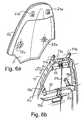
- FIG. 1Is a sketch-like drawing of the headrest section of a vehicle seat back with integrated headrest according to one embodiment of the invention in the position suitable for tilting the seat back forward,
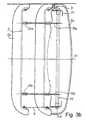
- FIGS. 2 a and 2 bare drawings of the headrest section of the vehicle seat according to FIG. 1 in the resting position and, respectively, in the tilted-forward position with a covering cuff removed,
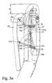
- FIGS. 3 a and 3 bare drawings of the mechanical construction of the headrest section of a vehicle seat according to one embodiment of the invention in resting and tilted-forward position, respectively, as a sectional drawing along a vertical (FIG. 3 a ) or a horizontal (FIG. 3 b ) plane of section,
- FIGS. 4 a to 4 care perspective partial views to explain the mechanical construction of the headrest section of a vehicle seat according to a first embodiment of the invention
- FIGS. 5 a and 5 bare perspective partial views to explain the mechanical construction of the headrest section of a vehicle seat slightly modified from the embodiment according to FIGS. 4 a to 4 c,
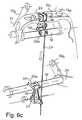
- FIGS. 6 a to 6 care perspective partial views to explain the mechanical construction of the headrest section of a vehicle seat according to a second embodiment of the invention.
- FIGS. 7 a to 7 care perspective partial views to explain the mechanical construction of the headrest section of a vehicle seat according to a third embodiment of the invention.
- FIGS. 8 a to 8 care perspective partial views to explain the mechanical construction of the headrest section of a vehicle seat according to a fourth embodiment of the invention.
- FIGS. 9 a to 9 care detail views to explain the actuating mechanism for movement of the cushion carrier part of the headrest for a vehicle seat according to one embodiment of the invention.
- FIG. 1the headrest section of a seat back 3 of a vehicle seat 1 is shown in perspective, in the position suitable for tilting the seat back 3 forward.
- a cushion carrier part 5which comprises a headrest cushion 5 a separate from the upholstery of the rest of the seat, is displaced forward (toward the left in the drawing) and downward with respect to a headrest section 3 a of the seat back 3 , after the seat back has been disengaged by means of an unlocking lever 9 so as to be tilted forward.
- a covering cuff 7which connects the circumference of the headrest section 3 a to that of the cushion carrier part 5 , conceals a mechanism described in detail below, which mediates the lowering of the cushion carrier part 5 with respect to the seat back 3 .
- FIGS. 2 a and 2 bin drawings corresponding to those of FIG. 1, show the resting state of the vehicle seat 1 with seat back 3 locked upright (FIG. 2 a ) for comparison with the state in which the seat back is ready to be tilted forward (FIG. 2 b ).
- the covering cuff 7FIG. 1
- the dot-dashed lines A 1 , A 2denote the axes of rotation of two axles in the mechanism for moving the cushion carrier part.
- FIGS. 3 a and 3 bimportant parts of this mechanism are shown in both the resting and the tilted-forward position. It can be seen that in the seat-back frame 11 (here shown only in outline) two tubular sections 13 , 15 are disposed along the axes of rotation A 1 , A 2 , to one of which is welded an angled swivelling lever 17 a and to the other, a straight swivelling lever 19 a . Both levers 17 a , 19 a are shown both in the (upper) resting or locked position and in the (lower) tilting-forward position. The free ends of the swivelling levers 17 a , 19 a are rotatably seated in abutments 21 a , 23 a on the cushion carrier part 5 .
- each of the levers 17 a , 19 athat encloses the axis A 1 , A 2 is a pin 17 a , 19 a , and each of the pins 17 a , 19 a is retained within an eye 25 a , 25 b in a connecting rod 25 that extends between the levers 17 a , 19 a and connects them to one another in such a way that a swivelling movement of one lever is necessarily transmitted to the other.
- the connecting rod 25is shown only in the tilting-forward position of the swivelling levers.
- FIG. 3 bIn the cross-sectional drawing of FIG. 3 b it can be seen that the tubular section 15 bears two swivelling levers 19 a , 19 b arranged symmetrically with respect to a vertical midplane S 1 of the seat. In an analogous arrangement (not shown here) on the second tubular section 13 are disposed another pair of swivelling levers, of which lever 17 a is visible in FIG. 3 a .
- the covering cuff 7In the upper region of FIG. 3 b the covering cuff 7 can be seen in its folded-up state in the resting position, and in the lower region of the figure the covering cuff 7 is shown unfolded and expanded as it appears when the cushion carrier part 5 is in the position ready for tilting forward.
- FIGS. 3 a and 3 bStructure and function of the mechanism shown in FIGS. 3 a and 3 b are additionally clarified by the perspective drawings in FIGS. 4 a to 4 c , which show more details of the mechanism in a slightly modified embodiment.
- the cushion carrier part 5is first shown in perspective from the back. It is evident that the abutments 21 a , 21 b and 23 a , 23 b are each formed as pairs of approximately triangular projections that protrude from the back surface of the cushion carrier part 5 . Each comprises an opening (not specially numbered) through which a retention pin (not shown) can be inserted so that when the cushion carrier part 5 is set onto the swivelling levers 17 a , 17 b and 19 a , 19 b , the levers are rotatably connected to the abutments 21 a , 21 b and 23 a , 23 b respectively.
- a retaining hookis formed, which projects backward out of the back surface of the cushion carrier part 5 and serves to engage a retaining clip 29 (FIG. 4 c ), so that the cushion carrier part 5 is held firmly to the seat-back frame 11 (FIGS. 4 b and 4 c ) in the resting position.
- FIGS. 4 b and 4 cthe parts of the mechanism for moving the cushion carrier part 5 that are disposed in the seat-back frame 11 are shown. These are first, as shown in FIGS. 3 a and 3 b and discussed above, tubular sections 13 , 15 , each of which is disposed substantially horizontally on an axle 14 or 16 , respectively, so as to rotate about the axes of rotation A 1 , A 2 , and upon which are mounted the swivelling levers 17 a , 17 b and 19 a , 19 b in a manner fixedly rotating therewith; also visible is a connecting rod 25 ′ (modified from the embodiment according to FIGS. 3 a and 3 b ), which connects the levers 17 a and 19 a to one another.
- a connecting rod 25 ′modified from the embodiment according to FIGS. 3 a and 3 b
- each of the swivelling levers 17 a , 17 b and 19 a , 19 bcomprises near its free end a bore to engage the above-mentioned retention pin for connection to the abutments 21 a , 21 b and 23 a , 23 b , respectively, on the cushion carrier part 5 .
- the axles 14 , 16are supported in a manner fixedly rotating therewith in bores (not specially numbered) in the seat-back frame 11 by way of corresponding bushings 14 a , 14 b or 16 a , 16 b , respectively.
- torsion spring 31 a , 31 bFor each of the swivelling levers 19 a , 19 b , which here are on the front surface of the tubular section 15 , there is provided a torsion spring 31 a , 31 b coiled coaxially around the axis of rotation A 2 . Both torsion springs 31 a , 31 b are fixed by one end to the seat-back frame 11 and with the other end overlap the upper edge of the associated lever 19 a or 19 b , so as to exert a downward force on the levers.
- the torsion springs 31 a , 31 bsimultaneously press down the cushion carrier part 5 connected to the swivelling levers, as soon as the engagement between the retaining hook 27 on the cushion carrier part 5 and the retaining clip 29 is released.
- Bowden cables 33 and 35in order to actuate the swivelling levers 19 a , 19 b and the retaining clip 29 , there are provided Bowden cables 33 and 35 , respectively.
- One end 33 a of the Bowden cable 33is inserted into a restoring lever 37 , which is disposed on the tubular section 15 and in its region opposite the end 33 a of the Bowden cable 33 , with respect to the axis of rotation A 2 , comprises a claw 37 a that extends under the lower edge of the swivelling lever 19 a .
- a Bowden cable holder 39is attached to the adjacent section of the seat-back frame 11 , in which the end 33 b of the Bowden cable sheath is suspended in a manner known per se.
- the retaining clip 29is so mounted in its middle region that it can rotate about a vertical axis (not specially numbered) against the pretensioning or biassing force exerted by a torsion spring 30 , which in the released position acts with respect to the retaining hook 27 .
- a torsion spring 30At the end of the retaining clip 29 opposite the hooked section, with respect to the said vertical axis of rotation, an end 35 a of the Bowden cable 35 is suspended.
- FIGS. 3 a and 3 b and FIGS. 4 a to 4 cfunction as follows.
- the claw 37 apresses the swivelling lever 19 a upward along with the elements linked to it, namely the lever 19 b , which is seated on the same tubular section 15 , and the swivelling levers 17 a , 17 b , by way of the connecting rod 25 ′.
- the cushion carrier part 5attached to the swivelling levers, is moved from the tilting-forward position back into the resting position (FIG. 2 a ).
- FIGS. 5 a and 5 ban embodiment of the swivelling-lever mechanism that has been further modified from the preceding embodiments is sketched.
- the basic construction and the functional principleare the same as in the embodiments described above, so that most of the reference numerals are the same and the associated components need not be explained again.
- This embodimenthas a smaller number of individual components, which is advantageous with respect to manufacturing costs.
- the structure of the lower swivelling-lever mechanismcan best be seen in FIG. 5 b .
- the axle 16shown here without the bushings 16 a , 16 b , bears near its one end (on the left in the drawing) the torsion spring 31 , which has been pushed onto the axle 16 coaxially and with its one end is braced against the upper edge of the spring-action lever 41 while the other end—as can be seen in FIG. 5 a and is analogous to the embodiment according to FIGS. 4 a to 4 c —is fixed to the seat-back frame.
- a bore 16 cpasses radially through the axle 16 .
- a restoring lever 37constructed as in the preceding embodiment is welded to a short tubular section 15 ′ and together with the latter can be pushed onto the axle 16 .
- the end 33 a of the Bowden cable 33is fixed in a bore 37 b in the restoring lever 37 in order to actuate the latter.
- the second swivelling-lever part 191is also pushed onto the axle 16 .
- Thislikewise comprises a radial bore 19 c ′, which is aligned with the bore 16 c through the axle 16 so that the lower swivelling mechanism can be mounted.
- the second swivelling-lever part 19 ′is connected to the axle 16 in a manner fixedly rotating therewith.
- FIGS. 6 a to 6 cshow a fragmentary view of an embodiment that differs from the embodiment according to FIGS. 4 a to 4 c with respect to the retaining mechanism.
- the actual movement mechanismcorresponds to that according to FIGS. 4 a to 4 c , and its components (insofar as they have not been omitted entirely in
- FIGS. 6 b and 6 c to make clearer what is shown)are identified by the same numerals as in those figures and are not explained again here.
- a first retaining-lever holder 49To the upper horizontal section 11 a of the seat-back frame 11 is attached a first retaining-lever holder 49 , and to a cross-bar 11 b of the seat-back frame 11 , near the second axis of rotation A 2 , a second retaining-lever holder 51 is attached.
- each of the two retaining-lever holders 49 , 51is seated—by way of a torsion-spring element—a retaining lever 53 or 55 , respectively, which is so disposed and constructed as to engage with the first wire clamp 55 on the tubular section 13 or the second wire clamp 47 on the tubular section 15 .
- a catch section 53 a or 55 ais provided on each retaining lever , that can hook into the wire clamp 45 or 47 , respectively.
- the retaining levers 53 , 55each comprise an extension 53 b or 55 b , respectively, in each of which a guide hole (not specially numbered) is provided within which a traction wire 57 is held and fixed to the retaining lever 53 , 55 so that it cannot be pulled out.
- FIGS. 7 a to 7 cA further modified embodiment of the retaining mechanism is sketched in FIGS. 7 a to 7 c.
- the actual swivelling mechanismcorresponds to the mechanism shown in FIGS. 4 a to 4 c and described above, so that here again the same reference numerals are used and the corresponding components are not explained again.
- a modified cushion carrier part 5 ′which, in addition to the abutments 21 , 21 b , 23 , 23 b for the swivelling levers, comprises two pairs of holders 59 , 61 for a first and a second retention pin 63 , 65 .
- retaining-lever holders 67 , 69 for retaining levers 71 , 73are mounted on the seat-back frame 11 , one on the upper horizontal section 11 a and the other on the lower cross-bar 11 b.
- the retaining levers 71 , 73are seated in the retaining-lever holders 67 , 69 by way of torsion-spring elements and comprise hook-shaped catch sections 71 a , 73 a and —on the other side of the fulcrum—extending sections 71 b , 73 b at which the traction wire 57 acts.
- the function of the retaining mechanism in the present arrangement to a great extentcorresponds to that in the arrangement according to FIGS. 6 a to 6 c —with the difference that the retaining levers 71 , 73 do not engage with wire clamps on the rotatable tubular sections of the linkage mechanism, but rather hook behind the retention pins 63 , 65 on the back surface of the cushion carrier part 5 ′, and are disengaged at these sites by movement of the traction wire in the direction of the arrow.
- FIGS. 8 a to 8 ca further movement mechanism for embodying the invention, namely a combined pivot-and-slide mechanism.
- Another retaining mechanismis also sketched here.
- the individual elementscorrespond to those in the embodiments described above, they are identified by the same reference numerals as above and are not described again here.
- the arrangementcomprises, firstly, a cushion carrier part 5 ′′ with a headrest cushion 5 a , on the back surface of which the abutments 23 a , 23 b present in the previously described embodiments are again provided.
- two pairs of holders 75 a , 75 b for retention pins 77 a , 77 bare provided, which—in contrast to the embodiment shown in FIG. 7 a —are oriented substantially vertically and are both disposed below the abutments 23 a , 23 b .
- In the upper region of the cushion carrier part 5 ′′there are provided at the same level two holders 83 a , 83 b with guide pins 85 a , 85 b that point toward one another and are aligned on a common axis.
- the lower part of the movement mechanismhas practically the same structure as in the embodiments described previously (cf. in particular FIG. 4 b ); here, however, the construction is illustrated by an exploded drawing.
- the seat-back frameIn a position corresponding to the retention pins 77 a , 77 b on the cushion carrier part 5 ′′ there are provided on the seat-back frame (by way of holders not shown in detail here) two retaining clips 29 a , 29 b to engage the retention pins. These are actuated by means of Bowden cables 35 a , 35 b.
- a guide gate 79is mounted on the upper side of the upper horizontal section 11 a of the seat-back frame; it comprises two lateral guide grooves, of which only the groove 79 b is visible in the drawings.
- the guide pins 85 a , 85 b on the cushion carrier part 5 ′′extend into these grooves and slide within them when the swivelling levers 19 a , 19 b pivot about the axis of rotation A, thus guiding the upper section of the cushion carrier part in a movement that corresponds to the swivelling movement of the lower section.
- the cushion carrier part 5 ′′is locked in place and released by means of the retaining clips 29 a , 29 b and the retention pins 77 a , 77 b in basically the same way as in the embodiment according to FIGS. 4 a to 4 c —with the difference that in the embodiment described here two retention mechanisms are provided.
- FIGS. 9 a to 9 can embodiment of a Bowden cable actuating mechanism for the arrangements explained above is sketched.
- FIG. 9a special reference is made to the last-described embodiment of the movement mechanism, as shown in FIGS. 8 a to 8 c.
- FIG. 9 afirstly, shows schematically the the entire course of the Bowden cables 33 and 35 for actuation of the restoring lever 37 and the retaining clips 29 a , 29 b , respectively.
- the arrangement of the Bowden cables 33 , 35 with respect to these components of the movement and locking mechanismswas explained above.
- FIG. 9 ait can be seen in addition that at the upper end of the Bowden cable 35 is provided a cable extension 35 d for connection with the retaining clip 29 b . At the ends of the Bowden cables 33 , 35 away from the movement and retention mechanism the two cables are held together in a cable-connecting part 81 , which is set into a Bowden cable holder 83 .
- the Bowden cable-end fastening 85 containing the cable-end coupling 33 / 35 dis attached to a fixed seat-back mounting part 87
- the Bowden cable holder 83 containing the cable-connecting part 81is attached to a seat-back mounting part 89 that can pivot about a seat-back axis of rotation A 3 .
- Both seat-back mounting parts 87 , 89 and the hinge-sided ends and fixation elements of the Bowden cables 33 , 34are covered by a snap-on cap 91 .
- FIG. 9 cthe pivotable seat-back mounting part 89 and the hinge-sided components of the Bowden cable mechanism are shown in two different positions of the seat back, at an angle of 40° to one another. It can be seen here that when the seat back is pivoted out of the upright position into a tilted-forward position, the original tension on the Bowden cable 35 (shown here as an example) is relieved, whereas when the back is returned to the upright (resting) position, the cable is again placed under tension.
- a lowering of the separate part of the headrest with respect to the seat-back framecan also be accomplished by means of a pure sliding guide mechanism or in principle also by means of a simple, single-axis tilting mechanism.
- the sliding or folding over of the separate headrest partcan be performed manually in an especially simple embodiment.
- the disengagementcan also be brought about by way of the unlocking lever of the seat back or else a separate unlocking element.
- a separate unlocking elementinstead of attaching the actuating mechanism to the seat back or the hinge of the seat back as described above, an attachment adjacent thereto is also possible, such that the seat back or its movable hinge part acts on the adjacently disposed actuating element when the seat back is tilted forward.
Landscapes
- Engineering & Computer Science (AREA)
- Aviation & Aerospace Engineering (AREA)
- Transportation (AREA)
- Mechanical Engineering (AREA)
- Seats For Vehicles (AREA)
Abstract
Description
Claims (17)
Applications Claiming Priority (2)
| Application Number | Priority Date | Filing Date | Title |
|---|---|---|---|
| DE19944719ADE19944719C1 (en) | 1999-09-17 | 1999-09-17 | Automobile passenger seat for 2-door vehicle has integrated headrest moved relative to backrest frame as seat is pivoted forwards for reducing overall length of backrest |
| DE19944719 | 1999-09-17 |
Publications (1)
| Publication Number | Publication Date |
|---|---|
| US6550856B1true US6550856B1 (en) | 2003-04-22 |
Family
ID=7922445
Family Applications (1)
| Application Number | Title | Priority Date | Filing Date |
|---|---|---|---|
| US09/664,963Expired - Fee RelatedUS6550856B1 (en) | 1999-09-17 | 2000-09-17 | Vehicle seat |
Country Status (2)
| Country | Link |
|---|---|
| US (1) | US6550856B1 (en) |
| DE (1) | DE19944719C1 (en) |
Cited By (124)
| Publication number | Priority date | Publication date | Assignee | Title |
|---|---|---|---|---|
| US20040195894A1 (en)* | 2003-04-07 | 2004-10-07 | Nissan Motor Co., Ltd. | Vehicle headrest apparatus |
| US20050023878A1 (en)* | 2003-07-30 | 2005-02-03 | Itw Automotive Products Gmbh & Co. Kg | Neck rest for the back rest of automobile seats, in particular rear seats |
| US6890028B2 (en)* | 2001-12-27 | 2005-05-10 | Nissan Motor Co., Ltd. | Headrest apparatus for vehicle |
| US20050212342A1 (en)* | 2004-03-10 | 2005-09-29 | James Kain | Juvenile vehicle seat with movable headrest |
| US20050242640A1 (en)* | 2004-04-15 | 2005-11-03 | Barko Jerry S | Folding headrest assembly |
| US20050264078A1 (en)* | 2004-05-26 | 2005-12-01 | Lear Corporation | Automotive seat assembly with stowable headrest |
| US20050280296A1 (en)* | 2004-06-22 | 2005-12-22 | Toyota Jidosha Kabushiki Kaisha | Vehicle seat |
| US20060006709A1 (en)* | 2004-07-02 | 2006-01-12 | Honda Motor Co., Ltd. | Head rest device |
| US20060033376A1 (en)* | 2004-06-22 | 2006-02-16 | Toyota Jidosha Kabushiki Kaisha | Vehicle seat |
| US20070024096A1 (en)* | 2005-07-27 | 2007-02-01 | Aisin Seiki Kabushiki Kaisha | Vehicle seat slide device |
| EP1772130A1 (en)* | 2005-10-10 | 2007-04-11 | Degonda-Rehab S.A. | Adjustable headrest assembly |
| US20070096515A1 (en)* | 2005-11-02 | 2007-05-03 | Lear Corporation | Folding head restraint mechanism |
| US20070126275A1 (en)* | 2005-12-05 | 2007-06-07 | Lear Corporation | Vehicle seat system |
| US20070152487A1 (en)* | 2004-04-15 | 2007-07-05 | Windsor Machine & Stamping Ltd. | Foldable Headrest Assembly |
| US20070176473A1 (en)* | 2006-01-30 | 2007-08-02 | Aisin Seiki Kabushiki Kaisha | Headrest control apparatus for vehicle and method of controlling headrest control apparatus for vehicle |
| US20070284925A1 (en)* | 2004-03-10 | 2007-12-13 | Cosco Management, Inc. | Headrest actuator for juvenile vehicle seat |
| US7390058B2 (en)* | 2005-08-25 | 2008-06-24 | Aisin Seiki Kabushiki Kaisha | Headrest apparatus for vehicle |
| US20080191522A1 (en)* | 2007-02-14 | 2008-08-14 | Inoac Corporation | Headrest |
| US20080290713A1 (en)* | 2007-05-25 | 2008-11-27 | Shigeo Oda | Headrest device |
| US20080315636A1 (en)* | 2007-06-21 | 2008-12-25 | Lear Corporation | Integrated vehicle seat with active head restraint system |
| US20090033137A1 (en)* | 2007-08-03 | 2009-02-05 | Lear Corporation | Vehicle seat with adjustable head restraint |
| US20090184555A1 (en)* | 2005-04-04 | 2009-07-23 | Lear Corporation | Selective remote head restraint actuation |
| US20090234544A1 (en)* | 2008-03-17 | 2009-09-17 | Lear Corporation | Vehicle active head restraint system with a locking linkage |
| US20090243355A1 (en)* | 2006-11-21 | 2009-10-01 | Norbert Heeg | Crash-active system of a vehicle |
| US20100026061A1 (en)* | 2008-07-30 | 2010-02-04 | Trw Vehicle Safety Systems Inc. | Active head restraint for a vehicle seat |
| US20100026066A1 (en)* | 2007-01-31 | 2010-02-04 | Bayerische Motoren Werke Aktiengesellschaft | Backrest for a Vehicle Seat With an Upper Backrest Having Adjustable Inclination |
| US20100052372A1 (en)* | 2008-08-27 | 2010-03-04 | Hyundai Motor Company | Headrest Apparatus Moveable in Cooperation with Seat Back |
| US20100102605A1 (en)* | 2007-07-05 | 2010-04-29 | Aisin Seiki Kabushiki Kaisha | Vehicle seat device |
| US20100127548A1 (en)* | 2008-11-10 | 2010-05-27 | Gerd Truckenbrodt | Headrest for a vehicle |
| US20100244510A1 (en)* | 2006-01-06 | 2010-09-30 | Andreas Schmitz | Displaceable head restraint |
| US20110241392A1 (en)* | 2007-08-22 | 2011-10-06 | Johnson Control Technology Company | Vehicle seat |
| EP2540565A1 (en)* | 2011-07-01 | 2013-01-02 | Volvo Car Corporation | Vehicle seat having a head rest arrangement with an adjustable head cushion and method of manufacturing the vehicle seat |
| US20130033077A1 (en)* | 2011-08-03 | 2013-02-07 | Sean Belnick | Chair having a removable headrest cover |
| US20130106162A1 (en)* | 2011-10-28 | 2013-05-02 | Mahendra Raja K | Self-adjusting head restraint |
| US20130313880A1 (en)* | 2011-02-15 | 2013-11-28 | Toyota Jidosha Kabushiki Kaisha | Vehicle headrest device |
| US8727374B1 (en) | 2013-01-24 | 2014-05-20 | Ford Global Technologies, Llc | Vehicle seatback with side airbag deployment |
| CN103963684A (en)* | 2013-01-24 | 2014-08-06 | 福特全球技术公司 | Flexible Seatback System |
| US20140225413A1 (en)* | 2011-09-07 | 2014-08-14 | Johnson Controls Technology Company | Height-adjustable head restraint for a vehicle seat and vehicle seat with a height-adjustable head restraint |
| US8905431B1 (en) | 2013-09-24 | 2014-12-09 | Ford Global Technologies, Llc | Side airbag assembly for a vehicle seat |
| US20140368008A1 (en)* | 2013-06-18 | 2014-12-18 | Toyota Boshoku Kabushiki Kaisha | Headrests and vehicle seats having the same |
| US9016783B2 (en) | 2013-01-24 | 2015-04-28 | Ford Global Technologies, Llc | Thin seat flex rest composite cushion extension |
| US9016784B2 (en) | 2013-01-24 | 2015-04-28 | Ford Global Technologies, Llc | Thin seat leg support system and suspension |
| US9061616B2 (en) | 2013-01-24 | 2015-06-23 | Ford Global Technologies, Llc | Articulating headrest assembly |
| US9096157B2 (en) | 2013-01-24 | 2015-08-04 | Ford Global Technologies, Llc | Seating assembly with air distribution system |
| US9126508B2 (en) | 2013-01-24 | 2015-09-08 | Ford Global Technologies, Llc | Upper seatback pivot system |
| US9126504B2 (en) | 2013-01-24 | 2015-09-08 | Ford Global Technologies, Llc | Integrated thin flex composite headrest assembly |
| US9187019B2 (en) | 2013-10-17 | 2015-11-17 | Ford Global Technologies, Llc | Thigh support for customer accommodation seat |
| US9193284B2 (en) | 2013-06-11 | 2015-11-24 | Ford Global Technologies, Llc | Articulating cushion bolster for ingress/egress |
| US9216677B2 (en) | 2013-01-24 | 2015-12-22 | Ford Global Technologies, Llc | Quick-connect trim carrier attachment |
| US9302643B2 (en) | 2014-04-02 | 2016-04-05 | Ford Global Technologies, Llc | Vehicle seating assembly with side airbag deployment |
| US9315130B2 (en) | 2013-11-11 | 2016-04-19 | Ford Global Technologies, Llc | Articulating head restraint |
| US9333882B2 (en) | 2014-10-03 | 2016-05-10 | Ford Global Technologies, Llc | Manual upper seatback support |
| US9340131B1 (en) | 2014-11-06 | 2016-05-17 | Ford Global Technologies, Llc | Head restraint with a multi-cell bladder assembly |
| US9365142B1 (en) | 2015-01-20 | 2016-06-14 | Ford Global Technologies, Llc | Manual independent thigh extensions |
| US9365143B2 (en) | 2013-12-12 | 2016-06-14 | Ford Global Technologies, Llc | Rear seat modular cushion |
| US9399418B2 (en) | 2013-01-24 | 2016-07-26 | Ford Global Technologies, Llc | Independent cushion extension and thigh support |
| US9415713B2 (en) | 2013-01-24 | 2016-08-16 | Ford Global Technologies, Llc | Flexible seatback system |
| US9421894B2 (en) | 2014-04-02 | 2016-08-23 | Ford Global Technologies, Llc | Vehicle seating assembly with manual independent thigh supports |
| US9505322B2 (en) | 2013-10-25 | 2016-11-29 | Ford Global Technologies, Llc | Manual lumbar pump assembly |
| US9517777B2 (en) | 2014-11-06 | 2016-12-13 | Ford Global Technologies, Llc | Lane departure feedback system |
| US9527418B2 (en) | 2013-09-12 | 2016-12-27 | Ford Global Technologies, Llc | Semi rigid push/pull vented envelope system |
| US9527419B2 (en) | 2014-03-31 | 2016-12-27 | Ford Global Technologies, Llc | Vehicle seating assembly with manual cushion tilt |
| US9566930B2 (en) | 2015-03-02 | 2017-02-14 | Ford Global Technologies, Llc | Vehicle seat assembly with side-impact airbag deployment mechanism |
| US9566884B2 (en) | 2013-11-11 | 2017-02-14 | Ford Global Technologies, Llc | Powered head restraint electrical connector |
| US9573528B1 (en) | 2015-08-25 | 2017-02-21 | Ford Global Technologies, Llc | Integrated seatback storage |
| US9593642B2 (en) | 2014-12-19 | 2017-03-14 | Ford Global Technologies, Llc | Composite cam carrier |
| US9616776B1 (en) | 2015-11-16 | 2017-04-11 | Ford Global Technologies, Llc | Integrated power thigh extender |
| US9649963B2 (en) | 2014-03-04 | 2017-05-16 | Ford Global Technologies, Pllc | Trim and foam assembly for a vehicle seat |
| US9663000B2 (en) | 2015-01-16 | 2017-05-30 | Ford Global Technologies, Llc | Vehicle seat configured to improve access |
| US9688174B2 (en) | 2015-08-07 | 2017-06-27 | Ford Global Technologies, Llc | Multi-cell seat cushion assembly |
| US9694741B2 (en) | 2014-08-25 | 2017-07-04 | Ford Global Technologies, Llc | Ambient functional lighting of a seat |
| US9707877B2 (en) | 2015-01-20 | 2017-07-18 | Ford Global Technologies, Llc | Independent thigh extension and support trim carrier |
| US9718387B2 (en) | 2015-08-03 | 2017-08-01 | Ford Global Technologies, Llc | Seat cushion module for a vehicle seating assembly |
| US9756408B2 (en) | 2016-01-25 | 2017-09-05 | Ford Global Technologies, Llc | Integrated sound system |
| US9771003B2 (en) | 2014-10-29 | 2017-09-26 | Ford Global Technologies, Llc | Apparatus for customizing a vehicle seat for an occupant |
| US9776533B2 (en) | 2014-10-03 | 2017-10-03 | Ford Global Technologies, Llc | Torsion bar upper seatback support assembly |
| US9776543B2 (en) | 2016-01-25 | 2017-10-03 | Ford Global Technologies, Llc | Integrated independent thigh supports |
| US20170282757A1 (en)* | 2016-04-04 | 2017-10-05 | Ford Global Technologies, Llc | Anthropomorphic upper seatback |
| US9789790B2 (en) | 2014-10-03 | 2017-10-17 | Ford Global Technologies, Llc | Tuned flexible support member and flexible suspension features for comfort carriers |
| US9789794B1 (en)* | 2016-07-19 | 2017-10-17 | Ford Global Technologies, Llc | Active head restraint |
| US9802535B2 (en) | 2015-04-27 | 2017-10-31 | Ford Global Technologies, Llc | Seat having ambient lighting |
| US9802512B1 (en) | 2016-04-12 | 2017-10-31 | Ford Global Technologies, Llc | Torsion spring bushing |
| US20170313218A1 (en)* | 2016-04-27 | 2017-11-02 | Ford Global Technologies, Llc | Power head restraint flexible closeout cover |
| US9809131B2 (en) | 2015-12-04 | 2017-11-07 | Ford Global Technologies, Llc | Anthropomorphic pivotable upper seatback support |
| US9834166B1 (en) | 2016-06-07 | 2017-12-05 | Ford Global Technologies, Llc | Side airbag energy management system |
| US9845029B1 (en) | 2016-06-06 | 2017-12-19 | Ford Global Technologies, Llc | Passive conformal seat with hybrid air/liquid cells |
| US9849817B2 (en) | 2016-03-16 | 2017-12-26 | Ford Global Technologies, Llc | Composite seat structure |
| US9849856B1 (en) | 2016-06-07 | 2017-12-26 | Ford Global Technologies, Llc | Side airbag energy management system |
| US9902293B2 (en) | 2013-01-24 | 2018-02-27 | Ford Global Technologies, Llc | Independent cushion extension with optimized leg-splay angle |
| US9914378B1 (en) | 2016-12-16 | 2018-03-13 | Ford Global Technologies, Llc | Decorative and functional upper seatback closeout assembly |
| US9914421B2 (en) | 2016-01-15 | 2018-03-13 | Ford Global Technologies, Llc | Seatback flexible slip plane joint for side air bag deployment |
| US9931999B2 (en) | 2015-12-17 | 2018-04-03 | Ford Global Technologies, Llc | Back panel lower clip anchorage features for dynamic events |
| US9950652B2 (en)* | 2016-04-27 | 2018-04-24 | Ford Global Technologies, Llc | Telescoping head restraint |
| US9994135B2 (en) | 2016-03-30 | 2018-06-12 | Ford Global Technologies, Llc | Independent cushion thigh support |
| US10035442B2 (en) | 2016-01-25 | 2018-07-31 | Ford Global Technologies, Llc | Adjustable upper seatback module |
| US10046683B2 (en) | 2014-01-23 | 2018-08-14 | Ford Global Technologies, Llc | Suspension seat back and cushion system having an inner suspension panel |
| US10046681B2 (en) | 2016-04-12 | 2018-08-14 | Ford Global Technologies, Llc | Articulating mechanical thigh extension composite trim payout linkage system |
| US10046682B2 (en) | 2015-08-03 | 2018-08-14 | Ford Global Technologies, Llc | Back cushion module for a vehicle seating assembly |
| US10052990B2 (en) | 2016-01-25 | 2018-08-21 | Ford Global Technologies, Llc | Extended seatback module head restraint attachment |
| US10065570B2 (en) | 2014-12-10 | 2018-09-04 | Ford Global Technologies, Llc | Electronic device holder for a vehicle seat |
| US10081279B2 (en) | 2016-04-12 | 2018-09-25 | Ford Global Technologies, Llc | Articulating thigh extension trim tensioning slider mechanism |
| US10093214B2 (en) | 2016-01-14 | 2018-10-09 | Ford Global Technologies, Llc | Mechanical manual leg tilt |
| US10166895B2 (en) | 2016-06-09 | 2019-01-01 | Ford Global Technologies, Llc | Seatback comfort carrier |
| US20190047455A1 (en)* | 2016-02-29 | 2019-02-14 | Jifeng Automotive Interior Gmbh | Headrest with an improved adjustment device |
| US20190047452A1 (en)* | 2016-04-27 | 2019-02-14 | Ford Global Technologies, Llc | Power head restraint with flexible closeout cover member |
| US10220737B2 (en) | 2016-04-01 | 2019-03-05 | Ford Global Technologies, Llc | Kinematic back panel |
| US10239431B2 (en) | 2016-09-02 | 2019-03-26 | Ford Global Technologies, Llc | Cross-tube attachment hook features for modular assembly and support |
| US10279714B2 (en) | 2016-08-26 | 2019-05-07 | Ford Global Technologies, Llc | Seating assembly with climate control features |
| US10286818B2 (en) | 2016-03-16 | 2019-05-14 | Ford Global Technologies, Llc | Dual suspension seating assembly |
| US10286824B2 (en) | 2016-08-24 | 2019-05-14 | Ford Global Technologies, Llc | Spreader plate load distribution |
| US10351030B2 (en)* | 2017-09-14 | 2019-07-16 | Ford Global Technologies, Llc | Seat trim retention system with asymmetrical retention force |
| US10377279B2 (en) | 2016-06-09 | 2019-08-13 | Ford Global Technologies, Llc | Integrated decking arm support feature |
| US10391910B2 (en) | 2016-09-02 | 2019-08-27 | Ford Global Technologies, Llc | Modular assembly cross-tube attachment tab designs and functions |
| US20190308536A1 (en)* | 2018-04-10 | 2019-10-10 | Grammer Ag | Headrest |
| US10471874B2 (en) | 2014-09-02 | 2019-11-12 | Ford Global Technologies, Llc | Massage bladder matrix |
| US10493882B1 (en)* | 2018-05-29 | 2019-12-03 | Ford Global Technologies, Llc | Vehicle seatback with thoracic support actuated pillow |
| CN110816375A (en)* | 2018-08-07 | 2020-02-21 | 丰田自动车株式会社 | Vehicle seat |
| US10589650B2 (en)* | 2017-08-25 | 2020-03-17 | Nhk Spring Co., Ltd. | Headrest device |
| US10596936B2 (en) | 2017-05-04 | 2020-03-24 | Ford Global Technologies, Llc | Self-retaining elastic strap for vent blower attachment to a back carrier |
| US10625646B2 (en) | 2016-04-12 | 2020-04-21 | Ford Global Technologies, Llc | Articulating mechanical thigh extension composite trim payout linkage system |
| US10759318B2 (en)* | 2016-08-19 | 2020-09-01 | Adient Luxembourg Holding S.Á R.L. | Infinite adjustment mechanism for a head restraint |
| US10857920B2 (en)* | 2019-03-19 | 2020-12-08 | Faurecia Automotive Seating, Llc | Backrest for a vehicle seat |
| US11203276B1 (en)* | 2020-08-25 | 2021-12-21 | Faurecia Automotive Seating, Llc | Trim support for vehicle seat |
| US20220281361A1 (en)* | 2021-03-03 | 2022-09-08 | Ford Global Technologies, Llc | Seating assembly with displaceable panel |
Families Citing this family (3)
| Publication number | Priority date | Publication date | Assignee | Title |
|---|---|---|---|---|
| DE10104006C2 (en)* | 2001-01-31 | 2003-02-27 | Keiper Recaro Gmbh Co | Vehicle seat, in particular sports car seat |
| FR2986475B1 (en)* | 2012-02-07 | 2014-02-28 | Cera | HEADREST FOR THE SEAT OF A MOTOR VEHICLE |
| US10611283B2 (en) | 2018-09-12 | 2020-04-07 | Rockwell Collins, Inc. | Multi-stage seatback extension system |
Citations (21)
| Publication number | Priority date | Publication date | Assignee | Title |
|---|---|---|---|---|
| US2636552A (en)* | 1947-11-04 | 1953-04-28 | Hardman Tool & Engineering Co | Chair back |
| US3055707A (en)* | 1959-02-06 | 1962-09-25 | Albert M Spound | Adjustable headrest for reclining chairs |
| US4304439A (en)* | 1978-03-24 | 1981-12-08 | Aisin Seiki Kabushiki Kaisha | Head rest adjusting device |
| DE3300506A1 (en)* | 1983-01-08 | 1984-07-19 | G. Laauser GmbH & Co, 7141 Großbottwar | Upholstered furniture with head support |
| EP0209417A1 (en)* | 1985-06-12 | 1987-01-21 | Bertrand Faure Automobile | Adjustable head-rests, and seats equipped with such head-rests |
| DE3638261A1 (en)* | 1985-11-29 | 1987-06-04 | Aisin Seiki | Headrest device |
| US4693515A (en)* | 1986-10-27 | 1987-09-15 | Itt Corporation | Headrest for an automotive vehicle seat |
| US4840429A (en)* | 1987-08-14 | 1989-06-20 | Siemens Aktiengesellschaft | Motor-adjustable head support for a dental treatment chair |
| JPH03540A (en)* | 1989-05-29 | 1991-01-07 | Tachi S Co Ltd | Headrest control system and headrest control device |
| JPH048310A (en)* | 1990-04-26 | 1992-01-13 | Tachi S Co Ltd | Headrest control method and headrest control device |
| EP0471573A1 (en)* | 1990-08-17 | 1992-02-19 | General Engineering (Netherlands) B.V. | A vehicle seat arrangement |
| FR2708532A3 (en)* | 1993-08-06 | 1995-02-10 | Sepi Spa | Seat for a motor vehicle, particularly for a convertible car |
| US5590929A (en) | 1994-06-16 | 1997-01-07 | Bertrand Faure Equipements S.A. | Locking system for a device adjustable by translational motion, such as a headrest |
| US5738411A (en)* | 1997-01-23 | 1998-04-14 | Hoover Universal, Inc. | Vehicle seat assembly |
| US5918940A (en) | 1996-06-26 | 1999-07-06 | Aisin Seiki Kabushiki Kaisha | Seat having an adjusting mechanism for adjusting height of head rest |
| US5992937A (en)* | 1995-09-29 | 1999-11-30 | Ab Volvo | Adjustable neck rest |
| US6082817A (en)* | 1997-02-27 | 2000-07-04 | Inova Gmbh Technische Entwicklungen | Motor vehicle seat |
| US6192565B1 (en) | 1998-02-12 | 2001-02-27 | Magna Interior Systems Inc. | Automotive seat assembly having a rectractable headrest |
| US6270161B1 (en)* | 1998-07-09 | 2001-08-07 | Gestind M.B. Manifattura Di Bruzolo S.P.A. | Headrest for motor-vehicle seats |
| US6299254B1 (en)* | 1998-08-05 | 2001-10-09 | Daimlerchrysler Ag | Head restraint |
| US6302485B1 (en)* | 1999-08-09 | 2001-10-16 | Aisin Seiki Kabushiki Kaisha | Head rest device for vehicles |
- 1999
- 1999-09-17DEDE19944719Apatent/DE19944719C1/ennot_activeExpired - Fee Related
- 2000
- 2000-09-17USUS09/664,963patent/US6550856B1/ennot_activeExpired - Fee Related
Patent Citations (21)
| Publication number | Priority date | Publication date | Assignee | Title |
|---|---|---|---|---|
| US2636552A (en)* | 1947-11-04 | 1953-04-28 | Hardman Tool & Engineering Co | Chair back |
| US3055707A (en)* | 1959-02-06 | 1962-09-25 | Albert M Spound | Adjustable headrest for reclining chairs |
| US4304439A (en)* | 1978-03-24 | 1981-12-08 | Aisin Seiki Kabushiki Kaisha | Head rest adjusting device |
| DE3300506A1 (en)* | 1983-01-08 | 1984-07-19 | G. Laauser GmbH & Co, 7141 Großbottwar | Upholstered furniture with head support |
| EP0209417A1 (en)* | 1985-06-12 | 1987-01-21 | Bertrand Faure Automobile | Adjustable head-rests, and seats equipped with such head-rests |
| DE3638261A1 (en)* | 1985-11-29 | 1987-06-04 | Aisin Seiki | Headrest device |
| US4693515A (en)* | 1986-10-27 | 1987-09-15 | Itt Corporation | Headrest for an automotive vehicle seat |
| US4840429A (en)* | 1987-08-14 | 1989-06-20 | Siemens Aktiengesellschaft | Motor-adjustable head support for a dental treatment chair |
| JPH03540A (en)* | 1989-05-29 | 1991-01-07 | Tachi S Co Ltd | Headrest control system and headrest control device |
| JPH048310A (en)* | 1990-04-26 | 1992-01-13 | Tachi S Co Ltd | Headrest control method and headrest control device |
| EP0471573A1 (en)* | 1990-08-17 | 1992-02-19 | General Engineering (Netherlands) B.V. | A vehicle seat arrangement |
| FR2708532A3 (en)* | 1993-08-06 | 1995-02-10 | Sepi Spa | Seat for a motor vehicle, particularly for a convertible car |
| US5590929A (en) | 1994-06-16 | 1997-01-07 | Bertrand Faure Equipements S.A. | Locking system for a device adjustable by translational motion, such as a headrest |
| US5992937A (en)* | 1995-09-29 | 1999-11-30 | Ab Volvo | Adjustable neck rest |
| US5918940A (en) | 1996-06-26 | 1999-07-06 | Aisin Seiki Kabushiki Kaisha | Seat having an adjusting mechanism for adjusting height of head rest |
| US5738411A (en)* | 1997-01-23 | 1998-04-14 | Hoover Universal, Inc. | Vehicle seat assembly |
| US6082817A (en)* | 1997-02-27 | 2000-07-04 | Inova Gmbh Technische Entwicklungen | Motor vehicle seat |
| US6192565B1 (en) | 1998-02-12 | 2001-02-27 | Magna Interior Systems Inc. | Automotive seat assembly having a rectractable headrest |
| US6270161B1 (en)* | 1998-07-09 | 2001-08-07 | Gestind M.B. Manifattura Di Bruzolo S.P.A. | Headrest for motor-vehicle seats |
| US6299254B1 (en)* | 1998-08-05 | 2001-10-09 | Daimlerchrysler Ag | Head restraint |
| US6302485B1 (en)* | 1999-08-09 | 2001-10-16 | Aisin Seiki Kabushiki Kaisha | Head rest device for vehicles |
Cited By (183)
| Publication number | Priority date | Publication date | Assignee | Title |
|---|---|---|---|---|
| US6890028B2 (en)* | 2001-12-27 | 2005-05-10 | Nissan Motor Co., Ltd. | Headrest apparatus for vehicle |
| US20040195894A1 (en)* | 2003-04-07 | 2004-10-07 | Nissan Motor Co., Ltd. | Vehicle headrest apparatus |
| US7048334B2 (en)* | 2003-04-07 | 2006-05-23 | Nissan Motor Co., Ltd. | Vehicle headrest apparatus |
| US20050023878A1 (en)* | 2003-07-30 | 2005-02-03 | Itw Automotive Products Gmbh & Co. Kg | Neck rest for the back rest of automobile seats, in particular rear seats |
| US6942293B2 (en)* | 2003-07-30 | 2005-09-13 | Itw Automotive Products Gmbh & Co. Kg | Neck rest for the back rest of automobile seats, in particular rear seats |
| US7021710B2 (en)* | 2004-03-10 | 2006-04-04 | Cosco Management, Inc. | Juvenile vehicle seat with movable headrest |
| US20050212342A1 (en)* | 2004-03-10 | 2005-09-29 | James Kain | Juvenile vehicle seat with movable headrest |
| US20070284925A1 (en)* | 2004-03-10 | 2007-12-13 | Cosco Management, Inc. | Headrest actuator for juvenile vehicle seat |
| US7669926B2 (en) | 2004-03-10 | 2010-03-02 | Cosco Management, Inc. | Headrest actuator for juvenile vehicle seat |
| US20050242640A1 (en)* | 2004-04-15 | 2005-11-03 | Barko Jerry S | Folding headrest assembly |
| US20070152487A1 (en)* | 2004-04-15 | 2007-07-05 | Windsor Machine & Stamping Ltd. | Foldable Headrest Assembly |
| US7325877B2 (en) | 2004-04-15 | 2008-02-05 | Windsor Machine & Stamping Limited | Foldable headrest assembly |
| US7044555B2 (en)* | 2004-05-26 | 2006-05-16 | Lear Corporation | Automotive seat assembly with stowable headrest |
| US20050264078A1 (en)* | 2004-05-26 | 2005-12-01 | Lear Corporation | Automotive seat assembly with stowable headrest |
| US20060033376A1 (en)* | 2004-06-22 | 2006-02-16 | Toyota Jidosha Kabushiki Kaisha | Vehicle seat |
| US7044545B2 (en)* | 2004-06-22 | 2006-05-16 | Toyota Jidosha Kabushiki Kaisha | Vehicle seat |
| US20050280296A1 (en)* | 2004-06-22 | 2005-12-22 | Toyota Jidosha Kabushiki Kaisha | Vehicle seat |
| US7234769B2 (en)* | 2004-06-22 | 2007-06-26 | Toyota Jidosha Kabushiki Kaisha | Vehicle seat |
| US20060006709A1 (en)* | 2004-07-02 | 2006-01-12 | Honda Motor Co., Ltd. | Head rest device |
| US7641280B2 (en)* | 2004-07-02 | 2010-01-05 | Honda Motor Co., Ltd. | Head rest device |
| US20090184555A1 (en)* | 2005-04-04 | 2009-07-23 | Lear Corporation | Selective remote head restraint actuation |
| US8152242B2 (en)* | 2005-04-04 | 2012-04-10 | Lear Corporation | Selective remote head restraint actuation |
| US7445282B2 (en)* | 2005-07-27 | 2008-11-04 | Aisin Seiki Kabushiki Kaisha | Vehicle seat slide device |
| US20070024096A1 (en)* | 2005-07-27 | 2007-02-01 | Aisin Seiki Kabushiki Kaisha | Vehicle seat slide device |
| US7390058B2 (en)* | 2005-08-25 | 2008-06-24 | Aisin Seiki Kabushiki Kaisha | Headrest apparatus for vehicle |
| EP1772130A1 (en)* | 2005-10-10 | 2007-04-11 | Degonda-Rehab S.A. | Adjustable headrest assembly |
| US20070085401A1 (en)* | 2005-10-10 | 2007-04-19 | Kurt Hunziker | Adjustable head support for a chair |
| US20070096515A1 (en)* | 2005-11-02 | 2007-05-03 | Lear Corporation | Folding head restraint mechanism |
| US7322646B2 (en) | 2005-11-02 | 2008-01-29 | Lear Corporation | Folding head restraint mechanism |
| US20070126275A1 (en)* | 2005-12-05 | 2007-06-07 | Lear Corporation | Vehicle seat system |
| US7748787B2 (en) | 2005-12-05 | 2010-07-06 | Lear Corporation | Vehicle seat system |
| US20100244510A1 (en)* | 2006-01-06 | 2010-09-30 | Andreas Schmitz | Displaceable head restraint |
| US7448677B2 (en)* | 2006-01-30 | 2008-11-11 | Aisin Seiki Kabushiki Kaisha | Headrest control apparatus for vehicle and method of controlling headrest control apparatus for vehicle |
| US20070176473A1 (en)* | 2006-01-30 | 2007-08-02 | Aisin Seiki Kabushiki Kaisha | Headrest control apparatus for vehicle and method of controlling headrest control apparatus for vehicle |
| US20090243355A1 (en)* | 2006-11-21 | 2009-10-01 | Norbert Heeg | Crash-active system of a vehicle |
| US8033610B2 (en)* | 2007-01-31 | 2011-10-11 | Bayerische Motoren Werke Aktiengesellschaft | Backrest for a vehicle seat with an upper backrest having adjustable inclination |
| US20100026066A1 (en)* | 2007-01-31 | 2010-02-04 | Bayerische Motoren Werke Aktiengesellschaft | Backrest for a Vehicle Seat With an Upper Backrest Having Adjustable Inclination |
| US20080191522A1 (en)* | 2007-02-14 | 2008-08-14 | Inoac Corporation | Headrest |
| US7845721B2 (en)* | 2007-02-14 | 2010-12-07 | Inoac Corporation | Headrest |
| US7648200B2 (en)* | 2007-05-25 | 2010-01-19 | Toyoshi Fukuda | Headrest device |
| US20080290713A1 (en)* | 2007-05-25 | 2008-11-27 | Shigeo Oda | Headrest device |
| US7992933B2 (en) | 2007-06-21 | 2011-08-09 | Lear Corporation | Integrated vehicle seat with active head restraint system |
| US20080315636A1 (en)* | 2007-06-21 | 2008-12-25 | Lear Corporation | Integrated vehicle seat with active head restraint system |
| CN101327755B (en)* | 2007-06-21 | 2011-10-19 | 李尔公司 | Integrated vehicle seat with active head protecting system |
| US20100102605A1 (en)* | 2007-07-05 | 2010-04-29 | Aisin Seiki Kabushiki Kaisha | Vehicle seat device |
| US7845729B2 (en)* | 2007-07-05 | 2010-12-07 | Aisin Seiki Kabushiki Kaisha | Vehicle seat device |
| US20090033137A1 (en)* | 2007-08-03 | 2009-02-05 | Lear Corporation | Vehicle seat with adjustable head restraint |
| US7922252B2 (en)* | 2007-08-03 | 2011-04-12 | Lear Corporation | Vehicle seat with adjustable head restraint |
| US8608241B2 (en)* | 2007-08-22 | 2013-12-17 | Johnson Controls Technology Company | Vehicle seat |
| US20110241392A1 (en)* | 2007-08-22 | 2011-10-06 | Johnson Control Technology Company | Vehicle seat |
| US8100472B2 (en) | 2008-03-17 | 2012-01-24 | Lear Corporation | Vehicle active head restraint system with a locking linkage |
| US20090234544A1 (en)* | 2008-03-17 | 2009-09-17 | Lear Corporation | Vehicle active head restraint system with a locking linkage |
| US8205941B2 (en) | 2008-07-30 | 2012-06-26 | Trw Vehicle Safety Systems Inc. | Active head restraint for a vehicle seat |
| US20100026061A1 (en)* | 2008-07-30 | 2010-02-04 | Trw Vehicle Safety Systems Inc. | Active head restraint for a vehicle seat |
| US20100052372A1 (en)* | 2008-08-27 | 2010-03-04 | Hyundai Motor Company | Headrest Apparatus Moveable in Cooperation with Seat Back |
| US20110221238A1 (en)* | 2008-08-27 | 2011-09-15 | Hyundai Motor Company | Headrest apparatus moveable in cooperation with seat back |
| US8083287B2 (en)* | 2008-08-27 | 2011-12-27 | Hyundai Motor Company | Headrest apparatus moveable in cooperation with seat back |
| US7967375B2 (en)* | 2008-08-27 | 2011-06-28 | Hyundai Motor Company | Headrest apparatus moveable in cooperation with seat back |
| US20100127548A1 (en)* | 2008-11-10 | 2010-05-27 | Gerd Truckenbrodt | Headrest for a vehicle |
| US8616633B2 (en)* | 2008-11-10 | 2013-12-31 | Grammer Ag | Headrest for a vehicle |
| US20130313880A1 (en)* | 2011-02-15 | 2013-11-28 | Toyota Jidosha Kabushiki Kaisha | Vehicle headrest device |
| US9090184B2 (en)* | 2011-02-15 | 2015-07-28 | Toyota Jidosha Kabushiki Kaisha | Vehicle headrest device |
| CN102848950A (en)* | 2011-07-01 | 2013-01-02 | 沃尔沃汽车公司 | Vehicle seat and method of manufacturing vehicle seat |
| US20130001989A1 (en)* | 2011-07-01 | 2013-01-03 | Volvo Car Corporation | Vehicle seat having a head rest arrangement with an adjustable head cushion and method of manufacturing the vehicle seat |
| CN102848950B (en)* | 2011-07-01 | 2016-12-21 | 沃尔沃汽车公司 | Seat and the method manufacturing this seat |
| EP2540565A1 (en)* | 2011-07-01 | 2013-01-02 | Volvo Car Corporation | Vehicle seat having a head rest arrangement with an adjustable head cushion and method of manufacturing the vehicle seat |
| US9387785B2 (en)* | 2011-07-01 | 2016-07-12 | Volvo Car Corporation | Vehicle seat having a head rest arrangement with an adjustable head cushion and method of manufacturing the vehicle seat |
| US20130033077A1 (en)* | 2011-08-03 | 2013-02-07 | Sean Belnick | Chair having a removable headrest cover |
| US9446693B2 (en)* | 2011-09-07 | 2016-09-20 | Johnson Controls Technology Company | Height-adjustable head restraint for a vehicle seat and vehicle seat with a height-adjustable head restraint |
| US20140225413A1 (en)* | 2011-09-07 | 2014-08-14 | Johnson Controls Technology Company | Height-adjustable head restraint for a vehicle seat and vehicle seat with a height-adjustable head restraint |
| US20130106162A1 (en)* | 2011-10-28 | 2013-05-02 | Mahendra Raja K | Self-adjusting head restraint |
| US8931833B2 (en)* | 2011-10-28 | 2015-01-13 | Chrysler Group Llc | Self-adjusting head restraint |
| US9399418B2 (en) | 2013-01-24 | 2016-07-26 | Ford Global Technologies, Llc | Independent cushion extension and thigh support |
| US9707873B2 (en) | 2013-01-24 | 2017-07-18 | Ford Global Technologies, Llc | Flexible seatback system |
| US9016784B2 (en) | 2013-01-24 | 2015-04-28 | Ford Global Technologies, Llc | Thin seat leg support system and suspension |
| US9061616B2 (en) | 2013-01-24 | 2015-06-23 | Ford Global Technologies, Llc | Articulating headrest assembly |
| US8727374B1 (en) | 2013-01-24 | 2014-05-20 | Ford Global Technologies, Llc | Vehicle seatback with side airbag deployment |
| US9096157B2 (en) | 2013-01-24 | 2015-08-04 | Ford Global Technologies, Llc | Seating assembly with air distribution system |
| US9126508B2 (en) | 2013-01-24 | 2015-09-08 | Ford Global Technologies, Llc | Upper seatback pivot system |
| US9126504B2 (en) | 2013-01-24 | 2015-09-08 | Ford Global Technologies, Llc | Integrated thin flex composite headrest assembly |
| CN103963684B (en)* | 2013-01-24 | 2019-01-18 | 福特全球技术公司 | A kind of elastic chair back system |
| CN103963684A (en)* | 2013-01-24 | 2014-08-06 | 福特全球技术公司 | Flexible Seatback System |
| US9216677B2 (en) | 2013-01-24 | 2015-12-22 | Ford Global Technologies, Llc | Quick-connect trim carrier attachment |
| US9016783B2 (en) | 2013-01-24 | 2015-04-28 | Ford Global Technologies, Llc | Thin seat flex rest composite cushion extension |
| US9707870B2 (en) | 2013-01-24 | 2017-07-18 | Ford Global Technologies, Llc | Flexible seatback system |
| US9902293B2 (en) | 2013-01-24 | 2018-02-27 | Ford Global Technologies, Llc | Independent cushion extension with optimized leg-splay angle |
| US9873360B2 (en) | 2013-01-24 | 2018-01-23 | Ford Global Technologies, Llc | Flexible seatback system |
| US9873362B2 (en) | 2013-01-24 | 2018-01-23 | Ford Global Technologies, Llc | Flexible seatback system |
| US9649962B2 (en) | 2013-01-24 | 2017-05-16 | Ford Global Technologies, Llc | Independent cushion extension and thigh support |
| US9415713B2 (en) | 2013-01-24 | 2016-08-16 | Ford Global Technologies, Llc | Flexible seatback system |
| US9409504B2 (en) | 2013-01-24 | 2016-08-09 | Ford Global Technologies, Llc | Flexible seatback system |
| US9193284B2 (en) | 2013-06-11 | 2015-11-24 | Ford Global Technologies, Llc | Articulating cushion bolster for ingress/egress |
| US20140368008A1 (en)* | 2013-06-18 | 2014-12-18 | Toyota Boshoku Kabushiki Kaisha | Headrests and vehicle seats having the same |
| US9550438B2 (en)* | 2013-06-18 | 2017-01-24 | Toyota Boshoku Kabushiki Kaisha | Headrests and vehicle seats having the same |
| CN104228629A (en)* | 2013-06-18 | 2014-12-24 | 丰田纺织株式会社 | headrests and vehicle seats having the same |
| US9527418B2 (en) | 2013-09-12 | 2016-12-27 | Ford Global Technologies, Llc | Semi rigid push/pull vented envelope system |
| US8905431B1 (en) | 2013-09-24 | 2014-12-09 | Ford Global Technologies, Llc | Side airbag assembly for a vehicle seat |
| US9187019B2 (en) | 2013-10-17 | 2015-11-17 | Ford Global Technologies, Llc | Thigh support for customer accommodation seat |
| US9505322B2 (en) | 2013-10-25 | 2016-11-29 | Ford Global Technologies, Llc | Manual lumbar pump assembly |
| US9566884B2 (en) | 2013-11-11 | 2017-02-14 | Ford Global Technologies, Llc | Powered head restraint electrical connector |
| US9315130B2 (en) | 2013-11-11 | 2016-04-19 | Ford Global Technologies, Llc | Articulating head restraint |
| US9365143B2 (en) | 2013-12-12 | 2016-06-14 | Ford Global Technologies, Llc | Rear seat modular cushion |
| US10046683B2 (en) | 2014-01-23 | 2018-08-14 | Ford Global Technologies, Llc | Suspension seat back and cushion system having an inner suspension panel |
| US9649963B2 (en) | 2014-03-04 | 2017-05-16 | Ford Global Technologies, Pllc | Trim and foam assembly for a vehicle seat |
| US9527419B2 (en) | 2014-03-31 | 2016-12-27 | Ford Global Technologies, Llc | Vehicle seating assembly with manual cushion tilt |
| US9302643B2 (en) | 2014-04-02 | 2016-04-05 | Ford Global Technologies, Llc | Vehicle seating assembly with side airbag deployment |
| US9421894B2 (en) | 2014-04-02 | 2016-08-23 | Ford Global Technologies, Llc | Vehicle seating assembly with manual independent thigh supports |
| US10065546B2 (en) | 2014-04-02 | 2018-09-04 | Ford Global Technologies, Llc | Vehicle seating assembly with manual independent thigh supports |
| US9694741B2 (en) | 2014-08-25 | 2017-07-04 | Ford Global Technologies, Llc | Ambient functional lighting of a seat |
| US10471874B2 (en) | 2014-09-02 | 2019-11-12 | Ford Global Technologies, Llc | Massage bladder matrix |
| US9333882B2 (en) | 2014-10-03 | 2016-05-10 | Ford Global Technologies, Llc | Manual upper seatback support |
| US9789790B2 (en) | 2014-10-03 | 2017-10-17 | Ford Global Technologies, Llc | Tuned flexible support member and flexible suspension features for comfort carriers |
| US10369905B2 (en) | 2014-10-03 | 2019-08-06 | Ford Global Technologies, Llc | Tuned flexible support member and flexible suspension features for comfort carriers |
| US9776533B2 (en) | 2014-10-03 | 2017-10-03 | Ford Global Technologies, Llc | Torsion bar upper seatback support assembly |
| US9771003B2 (en) | 2014-10-29 | 2017-09-26 | Ford Global Technologies, Llc | Apparatus for customizing a vehicle seat for an occupant |
| US9340131B1 (en) | 2014-11-06 | 2016-05-17 | Ford Global Technologies, Llc | Head restraint with a multi-cell bladder assembly |
| US9517777B2 (en) | 2014-11-06 | 2016-12-13 | Ford Global Technologies, Llc | Lane departure feedback system |
| US10065570B2 (en) | 2014-12-10 | 2018-09-04 | Ford Global Technologies, Llc | Electronic device holder for a vehicle seat |
| US10525898B2 (en) | 2014-12-10 | 2020-01-07 | Ford Global Technologies, Llc | Electronic device holder for a vehicle seat |
| US9593642B2 (en) | 2014-12-19 | 2017-03-14 | Ford Global Technologies, Llc | Composite cam carrier |
| US9663000B2 (en) | 2015-01-16 | 2017-05-30 | Ford Global Technologies, Llc | Vehicle seat configured to improve access |
| US9365142B1 (en) | 2015-01-20 | 2016-06-14 | Ford Global Technologies, Llc | Manual independent thigh extensions |
| US9707877B2 (en) | 2015-01-20 | 2017-07-18 | Ford Global Technologies, Llc | Independent thigh extension and support trim carrier |
| US9566930B2 (en) | 2015-03-02 | 2017-02-14 | Ford Global Technologies, Llc | Vehicle seat assembly with side-impact airbag deployment mechanism |
| US10040415B2 (en) | 2015-03-02 | 2018-08-07 | Ford Global Technologies, Llc | Vehicle seat assembly with side-impact airbag deployment mechanism |
| US9802535B2 (en) | 2015-04-27 | 2017-10-31 | Ford Global Technologies, Llc | Seat having ambient lighting |
| US10046682B2 (en) | 2015-08-03 | 2018-08-14 | Ford Global Technologies, Llc | Back cushion module for a vehicle seating assembly |
| US9718387B2 (en) | 2015-08-03 | 2017-08-01 | Ford Global Technologies, Llc | Seat cushion module for a vehicle seating assembly |
| US9688174B2 (en) | 2015-08-07 | 2017-06-27 | Ford Global Technologies, Llc | Multi-cell seat cushion assembly |
| US9573528B1 (en) | 2015-08-25 | 2017-02-21 | Ford Global Technologies, Llc | Integrated seatback storage |
| US9616776B1 (en) | 2015-11-16 | 2017-04-11 | Ford Global Technologies, Llc | Integrated power thigh extender |
| US10239419B2 (en) | 2015-12-04 | 2019-03-26 | Ford Global Technologies, Llc | Anthropomorphic pivotable upper seatback support |
| US9809131B2 (en) | 2015-12-04 | 2017-11-07 | Ford Global Technologies, Llc | Anthropomorphic pivotable upper seatback support |
| US9931999B2 (en) | 2015-12-17 | 2018-04-03 | Ford Global Technologies, Llc | Back panel lower clip anchorage features for dynamic events |
| US10093214B2 (en) | 2016-01-14 | 2018-10-09 | Ford Global Technologies, Llc | Mechanical manual leg tilt |
| US9914421B2 (en) | 2016-01-15 | 2018-03-13 | Ford Global Technologies, Llc | Seatback flexible slip plane joint for side air bag deployment |
| US10035442B2 (en) | 2016-01-25 | 2018-07-31 | Ford Global Technologies, Llc | Adjustable upper seatback module |
| US9756408B2 (en) | 2016-01-25 | 2017-09-05 | Ford Global Technologies, Llc | Integrated sound system |
| US9776543B2 (en) | 2016-01-25 | 2017-10-03 | Ford Global Technologies, Llc | Integrated independent thigh supports |
| US10052990B2 (en) | 2016-01-25 | 2018-08-21 | Ford Global Technologies, Llc | Extended seatback module head restraint attachment |
| US20190047455A1 (en)* | 2016-02-29 | 2019-02-14 | Jifeng Automotive Interior Gmbh | Headrest with an improved adjustment device |
| US10654389B2 (en)* | 2016-02-29 | 2020-05-19 | Jifeng Automotive Interior Gmbh | Headrest with an improved adjustment device |
| US10286818B2 (en) | 2016-03-16 | 2019-05-14 | Ford Global Technologies, Llc | Dual suspension seating assembly |
| US9849817B2 (en) | 2016-03-16 | 2017-12-26 | Ford Global Technologies, Llc | Composite seat structure |
| US9994135B2 (en) | 2016-03-30 | 2018-06-12 | Ford Global Technologies, Llc | Independent cushion thigh support |
| US10220737B2 (en) | 2016-04-01 | 2019-03-05 | Ford Global Technologies, Llc | Kinematic back panel |
| US9889773B2 (en)* | 2016-04-04 | 2018-02-13 | Ford Global Technologies, Llc | Anthropomorphic upper seatback |
| US20170282757A1 (en)* | 2016-04-04 | 2017-10-05 | Ford Global Technologies, Llc | Anthropomorphic upper seatback |
| US10046681B2 (en) | 2016-04-12 | 2018-08-14 | Ford Global Technologies, Llc | Articulating mechanical thigh extension composite trim payout linkage system |
| US10081279B2 (en) | 2016-04-12 | 2018-09-25 | Ford Global Technologies, Llc | Articulating thigh extension trim tensioning slider mechanism |
| US10625646B2 (en) | 2016-04-12 | 2020-04-21 | Ford Global Technologies, Llc | Articulating mechanical thigh extension composite trim payout linkage system |
| US9802512B1 (en) | 2016-04-12 | 2017-10-31 | Ford Global Technologies, Llc | Torsion spring bushing |
| US10144321B2 (en)* | 2016-04-27 | 2018-12-04 | Ford Global Technologies, Llc | Power head restraint flexible closeout cover |
| US11027633B2 (en) | 2016-04-27 | 2021-06-08 | Ford Global Technologies, Llc | Power head restraint flexible closeout cover |
| US10703237B2 (en)* | 2016-04-27 | 2020-07-07 | Ford Global Technologies, Llc | Power head restraint with flexible closeout cover member |
| US9950652B2 (en)* | 2016-04-27 | 2018-04-24 | Ford Global Technologies, Llc | Telescoping head restraint |
| US20190047452A1 (en)* | 2016-04-27 | 2019-02-14 | Ford Global Technologies, Llc | Power head restraint with flexible closeout cover member |
| US20170313218A1 (en)* | 2016-04-27 | 2017-11-02 | Ford Global Technologies, Llc | Power head restraint flexible closeout cover |
| US10625644B2 (en) | 2016-04-27 | 2020-04-21 | Ford Global Technologies, Llc | Power head restraint flexible closeout cover |
| US9845029B1 (en) | 2016-06-06 | 2017-12-19 | Ford Global Technologies, Llc | Passive conformal seat with hybrid air/liquid cells |
| US9834166B1 (en) | 2016-06-07 | 2017-12-05 | Ford Global Technologies, Llc | Side airbag energy management system |
| US9849856B1 (en) | 2016-06-07 | 2017-12-26 | Ford Global Technologies, Llc | Side airbag energy management system |
| US10166895B2 (en) | 2016-06-09 | 2019-01-01 | Ford Global Technologies, Llc | Seatback comfort carrier |
| US10377279B2 (en) | 2016-06-09 | 2019-08-13 | Ford Global Technologies, Llc | Integrated decking arm support feature |
| US9789794B1 (en)* | 2016-07-19 | 2017-10-17 | Ford Global Technologies, Llc | Active head restraint |
| US10759318B2 (en)* | 2016-08-19 | 2020-09-01 | Adient Luxembourg Holding S.Á R.L. | Infinite adjustment mechanism for a head restraint |
| US10286824B2 (en) | 2016-08-24 | 2019-05-14 | Ford Global Technologies, Llc | Spreader plate load distribution |
| US10279714B2 (en) | 2016-08-26 | 2019-05-07 | Ford Global Technologies, Llc | Seating assembly with climate control features |
| US10391910B2 (en) | 2016-09-02 | 2019-08-27 | Ford Global Technologies, Llc | Modular assembly cross-tube attachment tab designs and functions |
| US10239431B2 (en) | 2016-09-02 | 2019-03-26 | Ford Global Technologies, Llc | Cross-tube attachment hook features for modular assembly and support |
| US9914378B1 (en) | 2016-12-16 | 2018-03-13 | Ford Global Technologies, Llc | Decorative and functional upper seatback closeout assembly |
| US10596936B2 (en) | 2017-05-04 | 2020-03-24 | Ford Global Technologies, Llc | Self-retaining elastic strap for vent blower attachment to a back carrier |
| US10589650B2 (en)* | 2017-08-25 | 2020-03-17 | Nhk Spring Co., Ltd. | Headrest device |
| US10351030B2 (en)* | 2017-09-14 | 2019-07-16 | Ford Global Technologies, Llc | Seat trim retention system with asymmetrical retention force |
| US10960802B2 (en)* | 2018-04-10 | 2021-03-30 | Grammer Ag | Headrest |
| US20190308536A1 (en)* | 2018-04-10 | 2019-10-10 | Grammer Ag | Headrest |
| US10493882B1 (en)* | 2018-05-29 | 2019-12-03 | Ford Global Technologies, Llc | Vehicle seatback with thoracic support actuated pillow |
| CN110816375A (en)* | 2018-08-07 | 2020-02-21 | 丰田自动车株式会社 | Vehicle seat |
| US10857920B2 (en)* | 2019-03-19 | 2020-12-08 | Faurecia Automotive Seating, Llc | Backrest for a vehicle seat |
| US11203276B1 (en)* | 2020-08-25 | 2021-12-21 | Faurecia Automotive Seating, Llc | Trim support for vehicle seat |
| US20220281361A1 (en)* | 2021-03-03 | 2022-09-08 | Ford Global Technologies, Llc | Seating assembly with displaceable panel |
| US11577631B2 (en)* | 2021-03-03 | 2023-02-14 | Ford Global Technologies, Llc | Seating assembly with displaceable panel |
| US12246625B2 (en) | 2021-03-03 | 2025-03-11 | Ford Global Technologies, Llc | Seating assembly with displaceable panel |
Also Published As
| Publication number | Publication date |
|---|---|
| DE19944719C1 (en) | 2001-01-11 |
Similar Documents
| Publication | Publication Date | Title |
|---|---|---|
| US6550856B1 (en) | Vehicle seat | |
| EP2210771B1 (en) | Stowable vehicle seat | |
| US5836648A (en) | Vehicle seat with multifunction backrest | |
| US7066543B2 (en) | Powered fold-flat seat hinge assembly | |
| EP1140552B1 (en) | Folding vehicle seat | |
| US20010040396A1 (en) | Head rest for a vehicle seat | |
| US6047444A (en) | Positive lock armrest mechanism | |
| EP1871638B1 (en) | Bench seat with movable bolsters | |
| EP2066525B1 (en) | Stand up seat assembly with retractable rear leg | |
| US20040251705A1 (en) | Easy entry seat with seat back mounted floor latch | |
| US5934732A (en) | Lock mechanism for foldable vehicle seat | |
| US8128162B2 (en) | Armrest assembly for a seat | |
| GB2155780A (en) | A seat having a pivotable back-rest | |
| US6983996B2 (en) | Safety headrest for a motor vehicle | |
| US5273241A (en) | Slide for a vehicle seat with a fixed return position system | |
| CA2706460C (en) | Manual retracting head restraint | |
| US6786552B2 (en) | Catch hook for a backrest adjustment armature in the seats of motor vehicles | |
| GB2318285A (en) | Vehicle seat having a retractable head restraint | |
| EP2046600B1 (en) | Seat assembly provided with an articulated-quadrilateral supporting device for a motor vehicle | |
| US20200094715A1 (en) | Vehicle seat comprising fitting arrangement and locking device | |
| JP2008528076A (en) | Vehicle seat with pivotable flap | |
| KR102784551B1 (en) | Seatback angle adjustment device for automobiles | |
| JPH0522437Y2 (en) | ||
| JPS6318262Y2 (en) | ||
| JPH0411542Y2 (en) |
Legal Events
| Date | Code | Title | Description |
|---|---|---|---|
| AS | Assignment | Owner name:LEAR CORPORATION, MICHIGAN Free format text:ASSIGNMENT OF ASSIGNORS INTEREST;ASSIGNORS:GANSER, ANTJE;KOBLISCHKE, ALEXANDER;REEL/FRAME:011377/0406 Effective date:20001011 | |
| AS | Assignment | Owner name:JPMORGAN CHASE BANK, N.A., AS GENERAL ADMINISTRATI Free format text:SECURITY AGREEMENT;ASSIGNOR:LEAR CORPORATION;REEL/FRAME:017858/0719 Effective date:20060425 | |
| FPAY | Fee payment | Year of fee payment:4 | |
| AS | Assignment | Owner name:JPMORGAN CHASE BANK, N.A., AS ADMINISTRATIVE AGENT Free format text:GRANT OF FIRST LIEN SECURITY INTEREST IN PATENT RIGHTS;ASSIGNOR:LEAR CORPORATION;REEL/FRAME:023519/0267 Effective date:20091109 Owner name:JPMORGAN CHASE BANK, N.A., AS ADMINISTRATIVE AGENT Free format text:GRANT OF SECOND LIEN SECURITY INTEREST IN PATENT RIGHTS;ASSIGNOR:LEAR CORPORATION;REEL/FRAME:023519/0626 Effective date:20091109 | |
| FPAY | Fee payment | Year of fee payment:8 | |
| AS | Assignment | Owner name:JPMORGAN CAHSE BANK, N.A., AS AGENT, ILLINOIS Free format text:SECURITY INTEREST;ASSIGNOR:LEAR CORPORATION;REEL/FRAME:030076/0016 Effective date:20130130 Owner name:JPMORGAN CHASE BANK, N.A., AS AGENT, ILLINOIS Free format text:SECURITY INTEREST;ASSIGNOR:LEAR CORPORATION;REEL/FRAME:030076/0016 Effective date:20130130 | |
| AS | Assignment | Owner name:LEAR CORPORATION, MICHIGAN Free format text:RELEASE BY SECURED PARTY;ASSIGNOR:JPMORGAN CHASE BANK, N.A.;REEL/FRAME:032722/0553 Effective date:20100830 | |
| AS | Assignment | Owner name:LEAR CORPORATION, MICHIGAN Free format text:RELEASE BY SECURED PARTY;ASSIGNOR:JPMORGAN CHASE BANK, N.A.;REEL/FRAME:032770/0843 Effective date:20100830 | |
| REMI | Maintenance fee reminder mailed | ||
| LAPS | Lapse for failure to pay maintenance fees | ||
| STCH | Information on status: patent discontinuation | Free format text:PATENT EXPIRED DUE TO NONPAYMENT OF MAINTENANCE FEES UNDER 37 CFR 1.362 | |
| FP | Expired due to failure to pay maintenance fee | Effective date:20150422 | |
| AS | Assignment | Owner name:LEAR CORPORATION, MICHIGAN Free format text:RELEASE BY SECURED PARTY;ASSIGNOR:JPMORGAN CHASE BANK, N.A., AS AGENT;REEL/FRAME:037701/0180 Effective date:20160104 Owner name:LEAR CORPORATION, MICHIGAN Free format text:RELEASE BY SECURED PARTY;ASSIGNOR:JPMORGAN CHASE BANK, N.A., AS AGENT;REEL/FRAME:037701/0340 Effective date:20160104 Owner name:LEAR CORPORATION, MICHIGAN Free format text:RELEASE BY SECURED PARTY;ASSIGNOR:JPMORGAN CHASE BANK, N.A., AS AGENT;REEL/FRAME:037701/0251 Effective date:20160104 | |
| AS | Assignment | Owner name:LEAR CORPORATION, MICHIGAN Free format text:RELEASE BY SECURED PARTY;ASSIGNOR:JPMORGAN CHASE BANK, N.A., AS AGENT;REEL/FRAME:037702/0911 Effective date:20160104 Owner name:LEAR CORPORATION, MICHIGAN Free format text:RELEASE BY SECURED PARTY;ASSIGNOR:JPMORGAN CHASE BANK, N.A., AS AGENT;REEL/FRAME:037731/0918 Effective date:20160104 |