US6550476B1 - Heat-moisture exchanger and nebulization device - Google Patents
Heat-moisture exchanger and nebulization deviceDownload PDFInfo
- Publication number
- US6550476B1 US6550476B1US09/082,665US8266598AUS6550476B1US 6550476 B1US6550476 B1US 6550476B1US 8266598 AUS8266598 AUS 8266598AUS 6550476 B1US6550476 B1US 6550476B1
- Authority
- US
- United States
- Prior art keywords
- housing
- chamber
- valves
- conduit
- passageway
- Prior art date
- Legal status (The legal status is an assumption and is not a legal conclusion. Google has not performed a legal analysis and makes no representation as to the accuracy of the status listed.)
- Expired - Fee Related
Links
Images


Classifications
- A—HUMAN NECESSITIES
- A61—MEDICAL OR VETERINARY SCIENCE; HYGIENE
- A61M—DEVICES FOR INTRODUCING MEDIA INTO, OR ONTO, THE BODY; DEVICES FOR TRANSDUCING BODY MEDIA OR FOR TAKING MEDIA FROM THE BODY; DEVICES FOR PRODUCING OR ENDING SLEEP OR STUPOR
- A61M16/00—Devices for influencing the respiratory system of patients by gas treatment, e.g. ventilators; Tracheal tubes
- A61M16/10—Preparation of respiratory gases or vapours
- A61M16/14—Preparation of respiratory gases or vapours by mixing different fluids, one of them being in a liquid phase
- A61M16/16—Devices to humidify the respiration air
- A—HUMAN NECESSITIES
- A61—MEDICAL OR VETERINARY SCIENCE; HYGIENE
- A61M—DEVICES FOR INTRODUCING MEDIA INTO, OR ONTO, THE BODY; DEVICES FOR TRANSDUCING BODY MEDIA OR FOR TAKING MEDIA FROM THE BODY; DEVICES FOR PRODUCING OR ENDING SLEEP OR STUPOR
- A61M16/00—Devices for influencing the respiratory system of patients by gas treatment, e.g. ventilators; Tracheal tubes
- A61M16/10—Preparation of respiratory gases or vapours
- A61M16/1045—Devices for humidifying or heating the inspired gas by using recovered moisture or heat from the expired gas
- A—HUMAN NECESSITIES
- A61—MEDICAL OR VETERINARY SCIENCE; HYGIENE
- A61M—DEVICES FOR INTRODUCING MEDIA INTO, OR ONTO, THE BODY; DEVICES FOR TRANSDUCING BODY MEDIA OR FOR TAKING MEDIA FROM THE BODY; DEVICES FOR PRODUCING OR ENDING SLEEP OR STUPOR
- A61M15/00—Inhalators
- A61M15/009—Inhalators using medicine packages with incorporated spraying means, e.g. aerosol cans
- A—HUMAN NECESSITIES
- A61—MEDICAL OR VETERINARY SCIENCE; HYGIENE
- A61M—DEVICES FOR INTRODUCING MEDIA INTO, OR ONTO, THE BODY; DEVICES FOR TRANSDUCING BODY MEDIA OR FOR TAKING MEDIA FROM THE BODY; DEVICES FOR PRODUCING OR ENDING SLEEP OR STUPOR
- A61M16/00—Devices for influencing the respiratory system of patients by gas treatment, e.g. ventilators; Tracheal tubes
- A61M16/08—Bellows; Connecting tubes ; Water traps; Patient circuits
- A61M16/0816—Joints or connectors
- A61M16/0841—Joints or connectors for sampling
- A61M16/085—Gas sampling
- A—HUMAN NECESSITIES
- A61—MEDICAL OR VETERINARY SCIENCE; HYGIENE
- A61M—DEVICES FOR INTRODUCING MEDIA INTO, OR ONTO, THE BODY; DEVICES FOR TRANSDUCING BODY MEDIA OR FOR TAKING MEDIA FROM THE BODY; DEVICES FOR PRODUCING OR ENDING SLEEP OR STUPOR
- A61M2230/00—Measuring parameters of the user
- A61M2230/40—Respiratory characteristics
- A61M2230/43—Composition of exhalation
- A61M2230/432—Composition of exhalation partial CO2 pressure (P-CO2)
- A—HUMAN NECESSITIES
- A62—LIFE-SAVING; FIRE-FIGHTING
- A62B—DEVICES, APPARATUS OR METHODS FOR LIFE-SAVING
- A62B9/00—Component parts for respiratory or breathing apparatus
- A62B9/003—Means for influencing the temperature or humidity of the breathing gas
Definitions
- This invention utilized in the medical fieldgenerally relates to an apparatus for the humidification of inspired gases and the administration of aerosolized medication in connection with mechanical ventilators, or anesthesia devices.
- Hygroscopic condensers humidifiersHH
- heat and moisture exchangersHME
- an artificial noseare well known in the art. These devices are routinely used for the humidification of inspired gases during mechanical ventilation.
- a patient requiring mechanical ventilation with the usual method of an electronic humidification apparatusdemand constant observation.
- the respiratory practitioner or nursemust assure that the reservoir of the humidifier is maintained with an adequate level of water, as well as the alarm system and heater are operating properly, and to assure a physiological proximal airway temperature.
- Another methodmay employ the connection of a container inline in the ventilator circuit, and a vacuum applied to remove the condensate collected in the container.
- Heated wire circuitsare frequently employed to reduce the amount of water condensation in the ventilator circuit. However, there is a greater cost associated with the combination of an electronic humidifier and heated wire circuit, compared to an electronic humidifier alone.
- a patient requiring mechanical ventilationwill receive an aerosolized medication with a nebulizer, or metered dose inhaler (MDI).
- a nebulizeris used to aerosolize a bronchodilator, the HME must be quickly removed from the ventilator circuit, and replaced with the nebulizer prefilled with a liquid medication, and “T” adaptor. After the nebulization is complete, the nebulizer and “T” adaptor are quickly disconnected, and then reattach the HME to the ventilator circuit.
- the exchange of componentsoccurs synchronously during the brief period of time between the end of the exhalation phase, and just prior to the next inspiratory phase.
- HMEObstruction of the HME device does not readily occur following a few actuations with an MDI. Therefore the HME is usually not removed prior to the use of an MDI alone. However, the HME should be removed with the combination of an MDI and spacer device, due to the added deadspace volume.
- Another disadvantage of frequent disconnections of the ventilator circuit to attach a nebulizerare the increase risk of nosocomial infections from the hospital environment, or secondary to improper hand washing technique.
- the medical personnelhas an increased risk of occupational hazards to the exposure of infectious airborne pathogens from a patient, such as tuberculosis, antibiotic resistant bacteria, and potential lethal viruses.
- U.S. Pat. No. 5,505,568 issued to Altadonnasets forth a HUMIDITY MOISTURE EXCHANGER in which the HME having a first and second chamber, the second chamber with a pair of fluid ports. Inside the housing, is a filter or heat and moisture collecting material. To permit the uninhibited passage of aerosol from the nebulizer, the absorbent material is removed from the second chamber area, and temporarily stored within the first chamber area.
- the deviceis designed to obviate the need for ventilator circuit disconnection, the device requires additional components and a nebulizer to administer an aerosol. It is unclear whether the described sealing engagement to minimize potential deadspace, could also provide an adequate seal to prevent aerosol clogging the filter, or heat and moisture collecting material when temporarily stored in the second chamber.
- U.S. Pat. No. 5,546,930 issued to Wikefeldtsets forth a PATIENT CONNECTOR WITH HME, FILTER, AND NEBULIZER CONNECTION in which a Y-piece is to provide an inhalation and exhalation conduit, a patient conduit for connecting the nipple to the Y-piece, an HME disposed in the patient conduit, a nebulizer connector between the nipple and the HME, or an inhalation connector downstream to the HME for connecting the patient conduit to the nebulizer.
- a powder inhaleris also provided in connection to the nipple so that powder can be supplied to the patient.
- a device for both humidification and aerosolizationfor connection to a mechanical ventilator, or anesthesia device.
- the apparatuscomprising of a first housing containing a material capable of absorbing heat and moisture from the exhaled air and transferring the heat and moisture to the inhaled air.
- a second housing for a nebulizeris rotatable with respect to the first housing to provide an aerosol.
- the first housinghaving an output fitting to be connected to an artificial airway of a patient.
- the second housinghaving an input fitting to be connected to a ventilator circuit and a second connection to a pressurized gas supply to the nebulizer.
- the first housingis partitioned into chambers.
- a mid chamberhaving at the forward end and integrated with the first housing, a flexible diaphragm.
- the mid chamberis constructed of a separate corrugated, or flexible casing. Disposed in the mid chamber, are two sections of an absorbent material, or a heat and moisture exchanger optionally impregnated with conventional hygroscopic substances. Two chambers lateral to the mid chamber provide passageways for the conveyance of the aerosol.
- a reciprocating memberInternal to the mid chamber, and between the two sections of the absorbent material, is a reciprocating member to open and close valves.
- the reciprocating memberis pulled backward and pushed forward by a linkage with the rotatable second housing.
- the linkageis provided by two pins at the rearward end of the reciprocating member, which engage two arcuate channels.
- Each arcuate channelis offset at an incline, having an arc length of 90 degrees, and located oppositely 180 degrees with respect to the other arcuate channel.
- the valvesdivert the primary gas flow or inspiratory stream to bypass the lateral chambers, to pass through the absorbent material and through the output fitting to the artificial airway.
- the patientpassively exhales through the output fitting, into the absorbent material to conserve heat and moisture.
- the reciprocating memberWhen the second housing is rotated 90 degrees counterclockwise, the reciprocating member is pulled backward, by the rotation of the arcuate channels which engage the two pins. In the pulled backward position, the reciprocating member positions the valves to divert the inspiratory stream to bypass the heat and moisture exchanger, and to pass through the lateral chambers, through the output fitting, to the artificial airway of the patient. At the end of the inspiratory phase, the patient passively exhales through the output fitting, through the lateral chambers and through the ventilator circuit.
- the second housingprovides a reservoir for receiving a liquid, a liquid nozzle, and a gas nozzle which is supplied by a pressurized gas source by means of a pressurized gas connector, an instillation port with cap to inject a liquid medication.
- the second housing or nebulizeris rotatable 90 degrees clockwise or counterclockwise on a conduit extending from the first housing. Therefore the conduit also provides an axle for the second housing.
- the conduit having rectangular openingsare normally closed by a concentric cylindrical sleeve of the second housing.
- the concentric sleeve having the same sized rectangular openingsare 90 degrees out of alignment with respect to the openings of an internal conduit, to provide a rotational sleeve valve.
- the reservoiris filled with an appropriate quantity of liquid medication, via the instillation port.
- the second housingis then rotated 90 degrees counterclockwise.
- the vertical orientation of the second housingwill allow the liquid medication to gravitate to a region of the liquid reservoir to be aspirated and aerosolized, when the pressurized gas source has been switched on to the gas nozzle.
- the 90 degree counterclockwise rotationopens the rectangular openings of the conduit automatically, to allow the aerosol from the interior of the second housing to be combined with the inspiratory stream.
- the second housingis returned to the horizontal orientation by rotating the second housing 90 degrees clockwise to resume the inspiratory stream through the heat and moisture exchanger.
- the horizontal to vertical orientation of the second housing or nebulizeris readily visualized by the medical personnel. This has the advantage to determine at a glance, whether the device is adjusted for the inspiratory stream to pass through the heat and moisture exchanger, or the device is adjusted for the inspiratory stream to deliver an aerosol, during operation of the nebulizer
- the input fittingis equipped with a nozzle and metered dose inhaler (MDI) adaptor.
- MDImetered dose inhaler
- the second housingis rotated 90 degrees counterclockwise, and the MDI is actuated in the usual manner.
- the reservoir of the second housing, and lateral chambers of the first housingprovides a spacer device for the MDI.
- the mid chamber of the first housingprovides a passageway for the conveyance of the aerosol, and the lateral chambers contain the heat and moisture exchange unit.
- a reciprocating memberInternal to the mid chamber is a reciprocating member, which is pushed forward or pulled backward by the same mechanism as described above, relative to the 90 degree clockwise and counterclockwise rotation of the second housing.
- the reciprocating memberis comprised of a resilient material having side walls. At each end of the reciprocating member, the side walls collapse or expand to provide valves. When the second housing is in the horizontal orientation, the reciprocating member is pulled backward to provide a force to collapse the valves. This prevents the inspiratory stream from entering the mid chamber.
- the inspiratory stream from the ventilator by means of the internal conduitwill bypass the second housing and is directed out the openings of the mid chamber, through the heat and moisture exchange unit, to the output fitting, to the artificial airway.
- the patientpassively exhales through the output fitting, and through the absorbent material, to conserve heat and moisture.
- the 90 degree counterclockwise rotation of the second housing in the vertical orientationpushes the reciprocating member forward. This releases the closing force on the resilient valves, and therefore the valves expand.
- the side walls of the reciprocating member in the forward positionalso closes the openings of the mid chamber.
- the inspiratory stream from the ventilator flowing through the second houseentraining the aerosol from the interior chamber of the second housing, to bypass the heat and moisture exchange unit through the output fitting to the artificial airway.
- the patientpassively exhales through the mid chamber through the ventilator circuit.
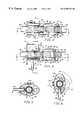
- FIG. 1is a perspective illustration of the invention
- FIG. 2is a perspective illustration of the invention, illustrating the rotational second housing
- FIG. 3is a cross sectional view taken along lines 3 — 3 of FIG. 1;
- FIG. 3Ais a detail enlargement of the valve sealing and thread means illustrated in FIG. 3;
- FIG. 4is a cross sectional view taken along lines 4 — 4 of FIG. 2;
- FIG. 4Ais a detail enlargement of the valve sealing means illustrated in FIG. 4;
- FIG. 5is a cross sectional view taken along lines 5 — 5 of FIG. 3;
- FIG. 6is a cross sectional view taken along lines 6 — 6 of FIG. 4; illustrating the rotational second housing;
- FIG. 6Ais a detail enlargement of the gas and liquid nozzle means, baffle and diminutive space illustrated in FIG. 6;
- FIG. 7is a cross sectional view taken along lines 7 — 7 of FIG. 3;
- FIG. 7Ais a detail enlargement of the valve sealing means illustrated in FIG. 7;
- FIG. 8is a cross sectional view taken along lines 8 — 8 of FIG. 4;
- FIG. 9is a cross sectional view taken along lines 9 — 9 of FIG. 7;
- FIG. 10is a cross sectional view taken along lines 4 — 4 of FIG. 2, illustrating the attachment of a metered dose inhaler container;
- FIG. 11is a cross sectional view of an alternate embodiment taken along lines 3 — 3 of FIG. 1;
- FIG. 12is a cross sectional view of the alternate embodiment taken along lines 4 — 4 of FIG. 2;
- FIG. 13is a cross sectional view of the alternate embodiment taken along lines 13 — 13 of FIG. 12;
- FIG. 14is a cross sectional view of the alternate embodiment taken along lines 14 — 14 of FIG. 13;
- FIG. 15is cross sectional view of an alternate embodiment taken along lines 3 — 3 of FIG. 1;
- FIG. 16is a cross sectional view of the alternate embodiment taken along lines 16 — 16 of FIG. 16;
- FIG. 17is a cross sectional view of the alternate embodiment taken along lines 4 — 4 of FIG. 2;
- FIG. 18is a cross sectional view of the alternate embodiment taken along lines 18 — 18 of FIG. 17;
- FIG. 19is cross sectional view of the alternate embodiment taken along lines 19 — 19 of FIG. 17 .
- FIG. 1 and FIG. 2are perspective views of the heat-moisture exchanger and nebulization device constructed in accordance to the present invention, and generally referenced by numeral 30 .
- the heat and moisture exchange unit and nebulizerincludes a first housing 32 and a second rotatable housing 34 .
- the second rotatable housing 32further includes a generally cylindrical input fitting 38 , and a generally cylindrical output fitting 36 , of the first housing 34 .
- Second rotatable housing 34further defines an outwardly extending pressure gas connector 40 , with gas conduit 42 , and a removable instillation cap 44 .
- the first housing 32is comprised of an elliptical shell 48 .
- the ends of the elliptical shell 48are sealed by elliptical end wall 46 , and elliptical end wall 50 .
- the interior of the first housingis partitioned into a mid chamber 90 and lateral chambers 88 .
- Within the mid chamberare two sections of an absorbent material 86 .
- a reciprocating member 80Positioned between the two sections of the absorbent material is a reciprocating member 80 .
- a cylindrical sleeve 98At the forward end on the reciprocating member 80 .
- a conical plug 83 and another cylindrical sleeve 100Toward the opposite end on the reciprocating member 80 .
- the reciprocating member 80 , elliptical end wall 46 , elliptical end wall 50 , and elliptical shell 48are constructed from a resilient material such as polypropylene, by injection and blow molding methods.
- a flexible diaphragm 92At the forward end of the elliptical shell 48 , is a flexible diaphragm 92 .
- the flexible diaphragm 92 having a central aperture 97is fitted in an annular groove 93 to join to the cylindrical sleeve 98 .
- the ring 99 on the annular surface of the cylindrical sleeve 98provides a seal between the cylindrical sleeve 98 and the inner diameter of the output fitting 36 .
- the ring 99also reduces the drag force of the seal during the backward and forward movement of the reciprocating member 80 .
- Extending from the elliptical end wall 46is a strut 96 which supports disc plug 94 with gussets 95 .
- the dimension of the outer diameter of the disc plug 94has a dimension in close tolerance to the inner diameter dimension of the cylindrical sleeve 98 . Therefore when the the reciprocating member 80 is pulled backward, the cylindrical sleeve 98 is guided by the strut 96 to the disc plug 94 , to form a seal between the outer diameter of the disc plug 94 , and the inner diameter of cylindrical sleeve 98 .
- the elliptical end wall 50is comprised of a double wall.
- the exterior elliptical end wall 50to seal the end of the elliptical shell 48 , and the internal wall 51 , to seal the end of the mid chamber 90 .
- a cylindrical passageway 75 with outlet ports 84is between the elliptical end wall 50 and the internal wall 51 .
- each interlocking pin 87is positioned 180 degrees relative to the other pin.
- the slots 82are parallel to the reciprocating member 80 , having a length to accommodate the forward and backward distance of travel of the reciprocating member 80 .
- Each slot 82is positioned 180 degrees relative to the other slot, in which the interlocking pins 87 project slightly through the corresponding slot 82 .
- the notch 102allows the interlocking pins 87 to partially bend inward on the cylindrical sleeve 100 , for the conduit 64 to receive the cylindrical sleeve 100 during assembly.
- the concentric sleeve 66provides two arcuate channels 78 , in which the arc length of the arcuate channel 78 is equivalent to accommodate the rotation of 90 degrees of the concentric sleeve 66 .
- the arcuate channels 78are offset at an incline, and engage the interlocking pins 87 , partially projecting through the slots 82 .
- the engagement of the interlocking pins 87 into the arcuate channels 78secures the rotatable second housing 34 to the conduit 64 . Rotational motion of the arcuate channels 78 , to provide a pull or push forward movement on the reciprocating member 80 .
- rings 99On the annular surface of cylindrical sleeve 100 are rings 99 , to provide a seal between the cylindrical sleeve 100 , and within the lumen of the cylindrical passageway 75 .
- the second housing 34is constructed of transparent plastic, such as polystyrene or K-Resin® by injection molding methods.
- the second housing 34is comprised of an elliptical shell 56 having an end wall 53 , and the opposite end of elliptical shell 56 , sealed by the elliptical end wall 54 .
- the concentric sleeve 66 with sleeve inlets 68extends from the internal end wall 53 to the end wall 54 . Extending from the end wall 53 , and adjacent to the concentric sleeve 66 , is a projection 71 .
- Projection 71is comprised of two parallel plane side walls to support a plane shelf wall, having two interior right angles, with respect to the two parallel plane side walls. Central to the shelf wall, is an orifice or, gas nozzle 70 . Extending outward and perpendicular from the plane shelf wall, and between the two parallel plane side walls is a pressurized gas connector 40 , with a gas conduit 42 in communication with the gas nozzle 70 .
- Projection 73Extending from the elliptical end wall 54 to the end wall 53 , is projection 73 .
- Projection 73is a slightly larger, and analogous in structure to projection 71 having two parallel plane side walls and a plane shelf wall with respect to the two parallel plane side walls, having two interior right angles. Central to the plane shelf wall is an orifice, or liquid nozzle 72 .
- the second housing 34projection 73 from the end wall 54 , slides over, to overlap projection 71 to form a diminutive space 74 , and provide the concentric alignment of gas nozzle 70 with liquid nozzle 72 .
- the high velocity gas exiting the gas nozzle 70 passing through the liquid nozzle 72will produce a subatmospheric pressure.
- the negative pressurewill aspirate a liquid within the diminutive space 74 , to the liquid nozzle 72 .
- the liquidis entrained and is added into the high velocity gas exiting the gas nozzle to create an aerosol.
- the aerosolcomprised of large and various sized liquid particles, impact on the baffle 76 , of the concentric sleeve 66 . This produces smaller and more uniform aerosol particle sizes.
- the assembled second housing 34is then swiveled on to the conduit 64 .
- the arcuate channels 78snap over the interlocking pins 87 protruding through the slots 82 , preventing the removal of the the second housing 34 .
- tabs 58extending from the elliptical end wall 50 are tabs 58 , and extending from the elliptical shell with end wall 56 are tabs 60 .
- Tabs 58 , and tabs 60provide stops to prevent rotating the second housing 34 beyond the 90 degree clockwise, or counterclockwise rotation.
- FIG. 3, FIG. 5, and FIG. 7illustrates the horizontal orientation of the second housing 34 with respect to the first housing 32 .
- the flow path of the primary gas flow or inspiratory stream from the ventilatoris indicated from left to right by the arrows “A” through the device to arrows “B”.
- the concentric sleeve 66cover and seal the inlet ports 62 of conduit 64 .
- the cylindrical sleeve 100is within the cylindrical passageway 75 to seal the outlet ports 84 , to prevent the primary gas flow entering the lateral chambers 88 .
- the cylindrical sleeve 98is within the output fitting 36 , to also seal the primary gas flow from entering the lateral chambers 88 .
- the patientpassively exhales designated by the exhalation flow path arrows “PE”.
- the flow path of “PE”through the output fitting 36 , into the heat and moisture exchange unit 86 , and through the input fitting, then through the ventilator circuit.
- the plug 44is first removed from the instillation port 52 , with the second housing 34 in the horizontal orientation. Due to the closure of the inlet ports 62 by the concentric sleeve 66 , no ventilator pressures or flows will escape out of the instillation port 52 . Also the regurgitation of liquid medication out of the instillation port 52 is prevented. An appropriate quantity of liquid medication is injected into the reservoir of the second housing 34 via the instillation port 52 . The plug 44 is returned and pressed fitted into the instillation port 52 .
- the second housing 34or nebulizer is rotated 90 degrees to a vertical orientation.
- the vertical orientation of the second housingwill allow the liquid medication to gravitate to the liquid reservoir.
- the pressurized gas source connected to the pressure gas connector 40is switched on to generate an aerosol.
- the flow path of the primary gas flow or inspiratory streamis indicated from left to right by the arrows “C” through the device to arrows “D”.
- the rotation of the second housing 34to cause rotation of the concentric sleeve 66 to align the sleeve inlet 68 to the inlet port 62 , and the rotation of the arcuate channels 78 to pull the reciprocating member 80 backward.
- the distance moved by the reciprocating member 80opens the outlet ports 84 by the backward displacement of the cylindrical sleeve 100 .
- the conical plug 83having an outer diameter dimension in close tolerance to the inner diameter of the cylindrical passageway 75 , is withdrawn within the cylindrical passageway 75 to seal and prevent the inspiratory stream from entering the mid chamber, and to divert the inspiratory stream to the lateral chambers 88 .
- the cylindrical sleeve 98is withdrawn to provide a seal around disc plug 94 to provide a seal to prevent the inspiratory stream to enter the mid chamber.
- the inspiratory streamenters input 38 , to be directed through the lateral chambers 88 , through the output fitting 36 , to bypass the heat and moisture exchange unit 86 .
- the opened inlet ports 62allow for aerosol entrainment indicated by the arrows “AE” to admix with the inspiratory stream.
- the patientpassively exhales indicated by the arrows “PE” through the output fitting 36 , through the lateral chambers 88 , through the input fitting 38 , then through the ventilator circuit.
- FIG. 10demonstrates an optional feature of the device as an MDI spacer.
- the input fitting 36is equipped with an MDI adaptor 106 , having a nozzle 108 .
- the second housing 34is rotated 90 degrees counterclockwise, to the vertical orientation.
- the outlet stem of the MDIis placed within the MDI adaptor 106 , then actuated in the usual manner, and removed after the delivery of the aerosolized medication.
- the second housing 34is then rotated 90 degrees clockwise to the horizontal orientation.
- FIGS. 11, 12 , 13 , 14is a alternate embodiment which utilizes the novel principle of operation set forth above.
- the mid chamberis comprised of a resilient plastic material such as polypropylene to provide a corrugated mid chamber 90 .
- the lateral chambers 88are formed between the corrugated mid chamber 90 and the internal wall of the elliptical shell 48 .
- the mid chamber 90can also be comprised of a substantially thin polyethylene encasing(not shown), or similar plastic material.
- One endis sealed around the cylindrical sleeve 98 .
- the cylindrical sleeve 98 , and cylindrical sleeve 100 , reciprocating member 80 , conical plug 83is injection injection molded into a unitary component.
- the two sections of the open-cell materialare placed into the polyethylene mid chamber 90 , and sealed around the internal end wall 51 .
- the elliptical end wall 50 with mid chamber 90 assemblyis ultrasonically welded to the elliptical shell 48 , having elliptical end wall 46 .
- FIG. 11 and FIG. 12is an optional socket 112 and cap 114 for the connection to a sampling tubing to monitor exhaled carbon dioxide.
- FIG. 13illustrates the position of the cylindrical sleeve 98 , conical plug 83 and cylindrical sleeve 100 , by the reciprocating member 80 .
- the flow path of the inspiratory streamis indicated by arrows “A” through the device to arrows “B” to flow through the heat and moisture exchange unit 86 , through the output fitting 36 , to the artificial airway of the patient.
- the patientpassively exhales indicated by arrows “PE” through the heat and moisture exchange unit 86 , through the input fitting, and through the ventilator circuit.
- FIG. 14the liquid medication has already been added via the instillation port 52 , with plug 44 secured.
- the second housing 34rotated 90 degrees counterclockwise, and the reciprocating member 80 is pulled backward by the same mechanism as previously described.
- the position of the cylindrical sleeve 98is sealed around the disc plug 94 , and the sealing position of the conical plug 83 , and cylindrical sleeve 100 , provide a bypass from the heat and moisture exchange unit.
- the pressurized gas source connected to the pressurized gas connector 40is switched on to generate an aerosol.
- the aerosol “AE”is entrained into the inspiratory stream indicated by arrows “C” through the device to arrows “D”.
- the inspiratory streamis directed through the lateral chambers 88 , and through the output fitting 36 , to the artificial airway of the patient.
- the patientpassively exhales indicated by “PE” through the output fitting 36 , through the lateral chambers 88 , through the input fitting, and through the ventilator circuit.
- FIGS. 15, 16 , 17 , 18 , 19is an alternate embodiment which utilizes the novel principle of operation set forth above.
- the interior of the first housing 32is partitioned into a mid chamber 90 , and lateral chambers 88 .
- the mid chamber 90in this configuration provides a passageway for the conveyance of an aerosol, and the lateral chambers 88 to contain the two sections of the heat and moisture exchange unit 86 .
- Disposed in the mid chamber 90is reciprocating member 80 .
- the reciprocating member 80is fabricated from a resilient material, which conforms within the internal structure of the mid chamber 90 .
- valves 118 and 120On the opposite ends of the reciprocating member 80 , are valves 118 and 120 . The reciprocating member 80 is pushed forward and pulled backward in the same manner previously described.
- the second housing 32is in the horizontal orientation.
- beveled guides 128Located on the floor and roof in the interior of the mid chamber 90 are beveled guides 128 .
- the beveled guides 128provide a closing force on the valves 120 .
- the valves 118are forced closed between the lateral tabs 126 and the internal wall of the mid chamber 90 .
- beveled supports 130Located on the floor and roof at the forward end of the reciprocating member 80 , are beveled supports 130 . The valves close against the beveled supports 130 , to provide additional sealing between the valves 118 , and beveled supports 130 .
- the flow path of the primary gas flow or inspiratory streamis indicated from arrows “A” through the device to arrows “B”.
- the inlet port 62is closed by the concentric sleeve 66 .
- the flow of the inspiratory stream after entering the conduit 64is prevented from entering the mid chamber 90 by the collapsed valves 120 , then exiting through the outlet ports 84 , through the heat and moisture exchange unit 86 , through the inlet openings 116 , and through the output fitting 36 , to the artificial airway.
- the patient exhalation flow path indicated by arrows “PE”through the output fitting port 36 .
- the collapsed valves 118deflect the patient exhaled gases indicated by “PE” from the mid chamber 90 , through the heat and moisture exchange unit 86 by means of the inlet openings 116 , through the input fitting, and through the ventilator circuit.
- the second housing 34 or nebulizeris rotated 90 degrees counterclockwise, in the vertical orientation.
- the reciprocating member 80is pushed forward. This releases the force on the valves 120 by the beveled guides 128 , allowing the valves 118 to expand. At the same time, the force is released on the lateral tabs 126 , to open the valves 120 .
- the valves 118are separated, and sealed between wedge support 122 , and the interior wall of the output fitting 36 . This provides a seal to close the inlet opening 116 . Additionally, the forward displacement of the reciprocating member 80 will move the rectangular sleeve 124 to close and seal the outlet ports 84 .
- the second housing 34is charged with an appropriate quantity of liquid medication, in the manner previously described.
- the pressurized gas sourceis switched on to generate an aerosol.
- the inspiratory streamis indicated from arrows “C” through the device to arrows “D”.
- the aerosolis entrained indicated by arrows “AE”, from the inspiratory stream, via the opened inlet ports 62 . Since the outlet port 84 and the inlet opening 116 are closed and sealed, the flow path of the inspiratory stream combined with the aerosol “AE”, is directed through the mid chamber 90 , to the output fitting 36 , providing a bypass from the heat and moisture exchange unit 86 .
- the patientpassively exhales “PE” through the mid chamber 90 , and through the ventilator circuit.
- a heat-moisture exchanger and nebulization devicerelatively simple and low cost to manufacture.
Landscapes
- Health & Medical Sciences (AREA)
- Emergency Medicine (AREA)
- Pulmonology (AREA)
- Engineering & Computer Science (AREA)
- Anesthesiology (AREA)
- Biomedical Technology (AREA)
- Heart & Thoracic Surgery (AREA)
- Hematology (AREA)
- Life Sciences & Earth Sciences (AREA)
- Animal Behavior & Ethology (AREA)
- General Health & Medical Sciences (AREA)
- Public Health (AREA)
- Veterinary Medicine (AREA)
- Nozzles (AREA)
Abstract
Description
Claims (36)
Priority Applications (1)
| Application Number | Priority Date | Filing Date | Title |
|---|---|---|---|
| US09/082,665US6550476B1 (en) | 1998-05-21 | 1998-05-21 | Heat-moisture exchanger and nebulization device |
Applications Claiming Priority (1)
| Application Number | Priority Date | Filing Date | Title |
|---|---|---|---|
| US09/082,665US6550476B1 (en) | 1998-05-21 | 1998-05-21 | Heat-moisture exchanger and nebulization device |
Publications (1)
| Publication Number | Publication Date |
|---|---|
| US6550476B1true US6550476B1 (en) | 2003-04-22 |
Family
ID=22172627
Family Applications (1)
| Application Number | Title | Priority Date | Filing Date |
|---|---|---|---|
| US09/082,665Expired - Fee RelatedUS6550476B1 (en) | 1998-05-21 | 1998-05-21 | Heat-moisture exchanger and nebulization device |
Country Status (1)
| Country | Link |
|---|---|
| US (1) | US6550476B1 (en) |
Cited By (90)
| Publication number | Priority date | Publication date | Assignee | Title |
|---|---|---|---|---|
| US20040084046A1 (en)* | 2002-10-30 | 2004-05-06 | Scott Halperin | Medication bypass heat and moisture exchange unit |
| US6745766B2 (en)* | 2000-03-29 | 2004-06-08 | Mallinckrodt Holdings B.V. | Heat and moisture exchanger |
| US20040118402A1 (en)* | 2002-12-19 | 2004-06-24 | Erkki Heinonen | Apparatus and method for use in non-invasively determining conditions in the circulatory system of a subject |
| US6792946B1 (en)* | 2003-08-13 | 2004-09-21 | James V. Waldo, Jr. | Heat-moisture exchanger with aerosol by-pass |
| WO2005047797A3 (en)* | 2003-11-10 | 2005-10-13 | Hudson Respiratory Care Inc | Moisture-heat exchanger unit |
| US20060033223A1 (en)* | 2000-06-30 | 2006-02-16 | Northgate Technologies, Inc. | Method and apparatus for humidification and warming of air |
| US20060078506A1 (en)* | 2004-05-20 | 2006-04-13 | Ralph Niven | Methods, systems and devices for noninvasive pulmonary delivery |
| US20060124127A1 (en)* | 2004-12-15 | 2006-06-15 | Newport Medical Instruments, Inc. | Humidifier system for artificial respiration |
| US20060137680A1 (en)* | 2002-08-23 | 2006-06-29 | Vladimir Sheiman | Nebulizing and drug delivery device |
| US7069928B1 (en) | 2005-03-04 | 2006-07-04 | Waldo Jr James V | Heat-moisture exchanger with aerosol by-pass |
| US20060144399A1 (en)* | 2004-12-17 | 2006-07-06 | Davidowski Doug L | Condensation reduction and management systems in a gas flow delivery system |
| US20060157056A1 (en)* | 2005-01-18 | 2006-07-20 | Burk Marc A | Heat and moisture exchange device for respiratory therapy |
| US20060201502A1 (en)* | 2005-03-09 | 2006-09-14 | Ric Investments, Llc. | Nebulizing drug delivery device with increased flow rate |
| US20060201500A1 (en)* | 2005-03-09 | 2006-09-14 | Ric Investments, Llc. | Nebulizing drug delivery device for ventilator |
| US20060201501A1 (en)* | 2005-03-09 | 2006-09-14 | Ric Investments, Llc | Nebulizing drug delivery device with interlock detection and temperature protection |
| US20060219243A1 (en)* | 2005-03-16 | 2006-10-05 | Walstrom Dennis R | HME/MDI apparatus having MDI in parallel to HME |
| US20060243274A1 (en)* | 2005-03-09 | 2006-11-02 | Ric Investments, Llc | Nebulizing drug delivery device with barrier |
| USD538922S1 (en)* | 2005-09-13 | 2007-03-20 | Smiths Group Plc | Airway heat and moisture exchanger |
| US20070068516A1 (en)* | 2004-03-30 | 2007-03-29 | Dhuper Sunil K | Aerosol inhalation systems and interface elements for use therein |
| US20070137644A1 (en)* | 2005-05-03 | 2007-06-21 | Dhuper Sunil K | Interface accessory for use with an aerosol inhalation system |
| WO2006127257A3 (en)* | 2005-05-23 | 2007-09-20 | Sunil Kumar Dhuper | Patient interface assemblies for use in ventilator systems to deliver medication to a patient |
| US20080053447A1 (en)* | 2006-08-29 | 2008-03-06 | Ratajczak John A | Adapter for air purifying filter |
| US20080066754A1 (en)* | 2006-09-15 | 2008-03-20 | Faram Joseph D | Continuous high-frequency oscillation breathing treatment apparatus |
| US20080087280A1 (en)* | 2005-05-03 | 2008-04-17 | Dhuper Sunil K | Interface accessory for use with an aerosol inhalation system |
| US20080099013A1 (en)* | 2005-01-06 | 2008-05-01 | Mark Andrew Graham | Gas-Treatment Devices |
| US20080101856A1 (en)* | 2006-10-25 | 2008-05-01 | Clawson Burrell E | Assemblies for coupling two elements and coupled assemblies |
| US20080236577A1 (en)* | 2007-03-28 | 2008-10-02 | John Sylvester Power | Humidification in Breathing Circuits |
| US20080283051A1 (en)* | 2007-05-18 | 2008-11-20 | Joseph Dee Faram | Lung therapy device |
| US20090020116A1 (en)* | 2007-07-17 | 2009-01-22 | Gary James Roth | Water dissipation device with capillary action |
| US20090020124A1 (en)* | 2007-07-17 | 2009-01-22 | Gary James Roth | Permeable membrane water dissipation device |
| US20090056715A1 (en)* | 2007-07-18 | 2009-03-05 | Vapotherm, Inc. | Delivery tube for breathing gas heating and humidification system |
| WO2009042187A1 (en)* | 2007-09-25 | 2009-04-02 | Nektar Therapeutics | Treatment of pulmonary disorders with aerosolized medicaments such as vancomycin |
| US20090104272A1 (en)* | 2007-10-10 | 2009-04-23 | Parion Sciences, Inc. | Inhaled hypertonic saline delivered by a heated nasal cannula |
| US20090200397A1 (en)* | 2005-05-23 | 2009-08-13 | Vladimir Lvovich Sheiman | Apparatus for atomisation and liquid filtration |
| US20090241948A1 (en)* | 2007-03-28 | 2009-10-01 | Dermot Joseph Clancy | Humidification in breathing circuits |
| US20090301476A1 (en)* | 2008-06-05 | 2009-12-10 | Neil Alex Korneff | Heat and moisture exchange unit |
| US20090301477A1 (en)* | 2008-06-05 | 2009-12-10 | Brian William Pierro | Heat and moisture exchange unit with check valve |
| US20090301475A1 (en)* | 2008-06-05 | 2009-12-10 | Neil Alex Korneff | Heat and moisture exchange unit |
| US7634998B1 (en)* | 2005-07-15 | 2009-12-22 | Fenley Robert C | HME shuttle system |
| US20100012127A1 (en)* | 2007-07-17 | 2010-01-21 | Teleflex Medical Incorporated | Water Dissipation Device and Method |
| US20100153158A1 (en)* | 2008-12-11 | 2010-06-17 | Sap Ag | Providing project management software application as enterprise services |
| US20100269828A1 (en)* | 2009-04-28 | 2010-10-28 | Axon Medical , Inc. | System, method and apparatus for removal of volatile anesthetics for malignant hyperthermia |
| US7841341B2 (en) | 2005-05-03 | 2010-11-30 | Aeon Research And Technology, Inc. | Interface accessory for use with an aerosol inhalation system |
| US20100313883A1 (en)* | 2006-04-20 | 2010-12-16 | Koninklijke Philips Electronics N.V. | Ultrasonic bebulilzer with metal coated ultrasonic genrator |
| US20110011395A1 (en)* | 2008-03-17 | 2011-01-20 | Discovery Laboratories, Inc. | Ventilation circuit adaptor and proximal aerosol delivery system |
| US7909033B2 (en) | 2006-05-03 | 2011-03-22 | Comedica Incorporated | Breathing treatment apparatus |
| US7921846B1 (en)* | 2002-09-16 | 2011-04-12 | Thayer Medical Corporation | Heat and moisture filter exchanger and method |
| US20110100360A1 (en)* | 2009-11-02 | 2011-05-05 | Joseph Dee Faram | Composite lung therapy device and method |
| US20110100364A1 (en)* | 2009-11-02 | 2011-05-05 | Joseph Dee Faram | Multiple conduit connector apparatus and method |
| US20110226250A1 (en)* | 2010-03-16 | 2011-09-22 | Carefusion 207, Inc | Seal for variable compression interfaces |
| WO2013037759A1 (en)* | 2011-09-15 | 2013-03-21 | Protecsom | Inhalation chamber to be built into a circuit of a mechanical-ventilation respiratory device |
| US8534280B2 (en) | 2007-11-19 | 2013-09-17 | Aeon Research and Technolgy Inc. | Patient interface member for use in an aerosol inhalation system |
| JP2013540033A (en)* | 2010-10-21 | 2013-10-31 | コーニンクレッカ フィリップス エヌ ヴェ | Humidifier bypass valve |
| US8746241B2 (en) | 2011-10-03 | 2014-06-10 | Sabrina B. Cavendish | Combination MDI and nebulizer adapter for a ventilator system |
| US8778383B2 (en) | 2011-06-07 | 2014-07-15 | Parion Sciences, Inc. | Methods of treatment |
| US8839791B2 (en) | 2011-06-22 | 2014-09-23 | Breathe Technologies, Inc. | Ventilation mask with integrated piloted exhalation valve |
| US8844766B2 (en) | 2009-07-14 | 2014-09-30 | Sterilogy, Llc | Dispenser assembly for dispensing disinfectant fluid and data collection and monitoring system for monitoring and reporting dispensing events |
| US8905026B2 (en) | 2005-04-28 | 2014-12-09 | Trudell Medical International | Ventilator circuit and method for the use thereof |
| US8945605B2 (en) | 2011-06-07 | 2015-02-03 | Parion Sciences, Inc. | Aerosol delivery systems, compositions and methods |
| US9038634B2 (en) | 2011-06-22 | 2015-05-26 | Breathe Technologies, Inc. | Ventilation mask with integrated piloted exhalation valve |
| USD736636S1 (en) | 2013-03-15 | 2015-08-18 | iMOLZ, LLC | Aerosol container |
| US20150343164A1 (en)* | 2014-05-30 | 2015-12-03 | Mercury Enterprises, Inc | Automated HME with Nebulizer Connection |
| US9242057B2 (en) | 2008-10-22 | 2016-01-26 | Trudell Medical International | Modular aerosol delivery system |
| US9289568B2 (en) | 2012-01-23 | 2016-03-22 | Aeon Research And Technology, Inc. | Gas delivery venturi |
| US20160136368A1 (en)* | 2014-11-19 | 2016-05-19 | Michael Spandorfer | Automated drug dispensing systems with automated hme bypass for ventilator circuits |
| USD762481S1 (en) | 2014-04-11 | 2016-08-02 | iMOLZ, LLC | Oval shaped can |
| US20160250438A1 (en)* | 2013-10-11 | 2016-09-01 | Fisher & Paykel Healthcare Limited | Hme and compact breathing apparatus |
| US9486602B2 (en) | 2011-06-22 | 2016-11-08 | Breathe Technologies, Inc. | Ventilation mask with integrated piloted exhalation valve and method of ventilating a patient using the same |
| US20170007798A1 (en)* | 2014-03-14 | 2017-01-12 | Fisher & Paykel Healthcare Limited | Humidification system |
| DE102016001408A1 (en)* | 2016-02-09 | 2017-08-10 | Drägerwerk AG & Co. KGaA | HME device for use in a breathing circuit of a respiratory system |
| US9795752B2 (en) | 2012-12-03 | 2017-10-24 | Mhs Care-Innovation, Llc | Combination respiratory therapy device, system, and method |
| US9878121B2 (en) | 2013-03-13 | 2018-01-30 | Breathe Technologies, Inc. | Ventilation mask with heat and moisture exchange device |
| AU2018201332A1 (en)* | 2017-02-27 | 2018-09-13 | Hill-Rom Services Pte. Ltd. | Respiratory therapy filter, flow control, and patient interface apparatuses, systems, and methods |
| US10398871B2 (en) | 2015-03-31 | 2019-09-03 | Vapotherm, Inc. | Systems and methods for patient-proximate vapor transfer for respiratory therapy |
| USD868235S1 (en)* | 2016-05-06 | 2019-11-26 | Atos Medical Ab | Heat and moisture exchanger component |
| US10556085B2 (en) | 2016-08-19 | 2020-02-11 | Christopher D. Warner | Heat-moisture exchanger with aerosol bypass |
| US10596345B2 (en) | 2014-12-31 | 2020-03-24 | Vapotherm, Inc. | Systems and methods for humidity control |
| US10894141B2 (en) | 2007-10-05 | 2021-01-19 | Vapotherm, Inc. | Hyperthermic humidification system |
| US10905837B2 (en) | 2015-04-02 | 2021-02-02 | Hill-Rom Services Pte. Ltd. | Respiratory therapy cycle control and feedback |
| CN114099876A (en)* | 2009-08-11 | 2022-03-01 | 瑞思迈发动机及马达技术股份有限公司 | Single-stage axisymmetric blower and portable ventilator |
| US11351330B2 (en) | 2016-10-14 | 2022-06-07 | Vapotherm, Inc. | Systems and methods for high velocity nasal insufflation |
| WO2022195246A1 (en)* | 2021-03-15 | 2022-09-22 | Smiths Medical International Limited | Gas-treatment devices |
| USD985758S1 (en) | 2019-11-12 | 2023-05-09 | Hill-Rom Services Pte. Ltd. | End piece of a pneumatic patient circuit |
| WO2023107911A1 (en)* | 2021-12-09 | 2023-06-15 | Avon Protection Systems, Inc. | Breathing apparatus system |
| US12064562B2 (en) | 2020-03-12 | 2024-08-20 | Vapotherm, Inc. | Respiratory therapy unit with non-contact sensing and control |
| US12070554B2 (en) | 2019-11-11 | 2024-08-27 | Hill-Rom Services Pte. Ltd. | Pneumatic connector apparatus and method |
| US12080401B2 (en) | 2012-12-03 | 2024-09-03 | Metrohealth Ventures Llc | Combination respiratory therapy device, system and method |
| US12168098B2 (en)* | 2016-07-19 | 2024-12-17 | Ventlab, Llc | Heat moisture exchanger (HME) having rotatable bypass channel for use in a medical ventilation system |
| US12280207B2 (en) | 2019-12-20 | 2025-04-22 | Hill-Rom Service Pte. Ltd. | Multi-mode respiratory therapy apparatus, system, and method |
| US12285565B2 (en) | 2020-08-24 | 2025-04-29 | Teleflex Medical Incorporated | Self-sealing respiratory filter and condensate management apparatus |
Citations (32)
| Publication number | Priority date | Publication date | Assignee | Title |
|---|---|---|---|---|
| US4195044A (en)* | 1975-04-18 | 1980-03-25 | Respiratory Care, Inc. | Humidifier-nebulizer |
| US4200094A (en)* | 1977-04-05 | 1980-04-29 | Siemens Aktiengesellschaft | Apparatus for warming and moistening a respiration gas |
| US4391616A (en)* | 1980-07-24 | 1983-07-05 | Toyo Boseki Kabushiki Kaisha | Method of dehumidification |
| US4512341A (en) | 1982-11-22 | 1985-04-23 | Lester Victor E | Nebulizer with capillary feed |
| US4699136A (en)* | 1983-12-22 | 1987-10-13 | Krauser Robert S | Method and apparatus for treating ailments |
| US4991643A (en)* | 1989-08-23 | 1991-02-12 | Hayden, Inc. | Heat exchanger with internal bypass valve |
| US5008048A (en) | 1988-12-05 | 1991-04-16 | Ryder Steven L | Position insensitive aspirator |
| US5109471A (en)* | 1989-07-24 | 1992-04-28 | Volker Lang | Device for warming and humidifying gases and more particularly respiratory gases during artificial respiration |
| US5165392A (en) | 1991-07-16 | 1992-11-24 | Small Jr John C | Accuvent aerosol delivery system |
| US5167679A (en)* | 1990-03-31 | 1992-12-01 | Taikisha Ltd. | Rotary gas treating apparatus |
| US5226411A (en)* | 1991-03-07 | 1993-07-13 | Walter Levine | Aerosol nebulizer heater |
| EP0590289A1 (en) | 1992-09-28 | 1994-04-06 | Engström Medical Ab | Patient connector |
| US5349946A (en)* | 1992-10-07 | 1994-09-27 | Mccomb R Carter | Microprocessor controlled flow regulated molecular humidifier |
| US5379760A (en) | 1992-10-26 | 1995-01-10 | Ryder; Steven L. | Position insensitive low resistance aspirator |
| US5388574A (en)* | 1993-07-29 | 1995-02-14 | Ingebrethsen; Bradley J. | Aerosol delivery article |
| US5460172A (en) | 1993-11-01 | 1995-10-24 | Artema Medical Ab | Moisture and heat exchanging unit for a respiration device |
| US5487382A (en) | 1991-10-30 | 1996-01-30 | Robert Bezicot | Tracheotomy filter for tracheotomy patients |
| US5505768A (en) | 1994-10-11 | 1996-04-09 | Altadonna; Anthony J. | Humidity moisture exchanger |
| US5577494A (en) | 1992-09-14 | 1996-11-26 | Minnesota Mining And Manufacturing Company | Superabsorbent fiber compositions demonstrating efficient retention of exhaled heat and moisture |
| US5615738A (en)* | 1994-06-29 | 1997-04-01 | Cecebe Technologies Inc. | Internal bypass valve for a heat exchanger |
| US5662161A (en)* | 1995-08-10 | 1997-09-02 | The United States Of America As Represented By The Secretary Of The Navy | Breathing gas cooling and heating device |
| WO1998022172A1 (en) | 1996-11-18 | 1998-05-28 | Medlis Corp. | Artificial ventilation system and methods of controlling carbon dioxide rebreathing |
| US5769071A (en)* | 1995-02-16 | 1998-06-23 | Smiths Industries Plc | Humidifier systems |
| US5829428A (en)* | 1996-05-29 | 1998-11-03 | Alliance Pharmaceutical Corp. | Methods and apparatus for reducing the loss of respiratory promoters |
| US5916493A (en)* | 1997-08-12 | 1999-06-29 | Pegasus Research Corporation | Humidifier system |
| US5964219A (en)* | 1996-06-27 | 1999-10-12 | Instrumentarium Oy | Method and arrangement for processing respiratory gas of an intubated patient |
| US5970210A (en)* | 1995-08-28 | 1999-10-19 | Ponnet, Gilman & Anthony Vof | Heated respiratory therapy humidifier |
| US5992413A (en)* | 1997-12-24 | 1999-11-30 | Enternet Medical, Inc. | Heat and moisture exchanger and generator |
| US6014972A (en)* | 1997-12-11 | 2000-01-18 | Thayer Medical Corporation | Dry drug particle delivery system and method for ventilator circuits |
| US6095135A (en)* | 1998-07-10 | 2000-08-01 | Enternet Medical, Inc. | Apparatus for providing benefits to respiratory gases |
| US6105576A (en)* | 1998-10-14 | 2000-08-22 | Enternet Medical, Inc. | Apparatus for treating respiratory gases including liquid trap |
| US6470882B1 (en)* | 1997-09-29 | 2002-10-29 | Michael T. Newhouse | Pernasal application of aerosol medication |
- 1998
- 1998-05-21USUS09/082,665patent/US6550476B1/ennot_activeExpired - Fee Related
Patent Citations (33)
| Publication number | Priority date | Publication date | Assignee | Title |
|---|---|---|---|---|
| US4195044A (en)* | 1975-04-18 | 1980-03-25 | Respiratory Care, Inc. | Humidifier-nebulizer |
| US4200094A (en)* | 1977-04-05 | 1980-04-29 | Siemens Aktiengesellschaft | Apparatus for warming and moistening a respiration gas |
| US4391616A (en)* | 1980-07-24 | 1983-07-05 | Toyo Boseki Kabushiki Kaisha | Method of dehumidification |
| US4512341A (en) | 1982-11-22 | 1985-04-23 | Lester Victor E | Nebulizer with capillary feed |
| US4699136A (en)* | 1983-12-22 | 1987-10-13 | Krauser Robert S | Method and apparatus for treating ailments |
| US5008048A (en) | 1988-12-05 | 1991-04-16 | Ryder Steven L | Position insensitive aspirator |
| US5109471A (en)* | 1989-07-24 | 1992-04-28 | Volker Lang | Device for warming and humidifying gases and more particularly respiratory gases during artificial respiration |
| US4991643A (en)* | 1989-08-23 | 1991-02-12 | Hayden, Inc. | Heat exchanger with internal bypass valve |
| US5167679A (en)* | 1990-03-31 | 1992-12-01 | Taikisha Ltd. | Rotary gas treating apparatus |
| US5226411A (en)* | 1991-03-07 | 1993-07-13 | Walter Levine | Aerosol nebulizer heater |
| US5165392A (en) | 1991-07-16 | 1992-11-24 | Small Jr John C | Accuvent aerosol delivery system |
| US5487382A (en) | 1991-10-30 | 1996-01-30 | Robert Bezicot | Tracheotomy filter for tracheotomy patients |
| US5577494A (en) | 1992-09-14 | 1996-11-26 | Minnesota Mining And Manufacturing Company | Superabsorbent fiber compositions demonstrating efficient retention of exhaled heat and moisture |
| EP0590289A1 (en) | 1992-09-28 | 1994-04-06 | Engström Medical Ab | Patient connector |
| US5546930A (en) | 1992-09-28 | 1996-08-20 | Engstrom Medical Aktiebolag | Patient connector with HME, filter, and nebulizer connection |
| US5349946A (en)* | 1992-10-07 | 1994-09-27 | Mccomb R Carter | Microprocessor controlled flow regulated molecular humidifier |
| US5379760A (en) | 1992-10-26 | 1995-01-10 | Ryder; Steven L. | Position insensitive low resistance aspirator |
| US5388574A (en)* | 1993-07-29 | 1995-02-14 | Ingebrethsen; Bradley J. | Aerosol delivery article |
| US5460172A (en) | 1993-11-01 | 1995-10-24 | Artema Medical Ab | Moisture and heat exchanging unit for a respiration device |
| US5615738A (en)* | 1994-06-29 | 1997-04-01 | Cecebe Technologies Inc. | Internal bypass valve for a heat exchanger |
| US5505768A (en) | 1994-10-11 | 1996-04-09 | Altadonna; Anthony J. | Humidity moisture exchanger |
| US5769071A (en)* | 1995-02-16 | 1998-06-23 | Smiths Industries Plc | Humidifier systems |
| US5662161A (en)* | 1995-08-10 | 1997-09-02 | The United States Of America As Represented By The Secretary Of The Navy | Breathing gas cooling and heating device |
| US5970210A (en)* | 1995-08-28 | 1999-10-19 | Ponnet, Gilman & Anthony Vof | Heated respiratory therapy humidifier |
| US5829428A (en)* | 1996-05-29 | 1998-11-03 | Alliance Pharmaceutical Corp. | Methods and apparatus for reducing the loss of respiratory promoters |
| US5964219A (en)* | 1996-06-27 | 1999-10-12 | Instrumentarium Oy | Method and arrangement for processing respiratory gas of an intubated patient |
| WO1998022172A1 (en) | 1996-11-18 | 1998-05-28 | Medlis Corp. | Artificial ventilation system and methods of controlling carbon dioxide rebreathing |
| US5916493A (en)* | 1997-08-12 | 1999-06-29 | Pegasus Research Corporation | Humidifier system |
| US6470882B1 (en)* | 1997-09-29 | 2002-10-29 | Michael T. Newhouse | Pernasal application of aerosol medication |
| US6014972A (en)* | 1997-12-11 | 2000-01-18 | Thayer Medical Corporation | Dry drug particle delivery system and method for ventilator circuits |
| US5992413A (en)* | 1997-12-24 | 1999-11-30 | Enternet Medical, Inc. | Heat and moisture exchanger and generator |
| US6095135A (en)* | 1998-07-10 | 2000-08-01 | Enternet Medical, Inc. | Apparatus for providing benefits to respiratory gases |
| US6105576A (en)* | 1998-10-14 | 2000-08-22 | Enternet Medical, Inc. | Apparatus for treating respiratory gases including liquid trap |
Cited By (189)
| Publication number | Priority date | Publication date | Assignee | Title |
|---|---|---|---|---|
| US6745766B2 (en)* | 2000-03-29 | 2004-06-08 | Mallinckrodt Holdings B.V. | Heat and moisture exchanger |
| US20040216739A1 (en)* | 2000-03-29 | 2004-11-04 | Massimo Fini | Heat and moisture exchanger |
| US6968841B2 (en)* | 2000-03-29 | 2005-11-29 | Mallinckrodt Holdings B.V. | Heat and moisture exchanger |
| US7762251B2 (en) | 2000-06-30 | 2010-07-27 | Northgate Technologies, Inc. | Method and apparatus for humidification and warming of air |
| US10052444B2 (en) | 2000-06-30 | 2018-08-21 | Northgate Technologies Inc. | Method and apparatus for humidification and warming of air |
| US8091546B2 (en) | 2000-06-30 | 2012-01-10 | Northgate Technologies, Inc. | Method and apparatus for humidification and warming of air |
| US8955511B2 (en) | 2000-06-30 | 2015-02-17 | Northgate Technologies, Inc. | Method and apparatus for humidification and warming of air |
| US7647925B2 (en)* | 2000-06-30 | 2010-01-19 | Northgate Technologies, Inc. | Method and apparatus for humidification and warming of air |
| US20100163044A1 (en)* | 2000-06-30 | 2010-07-01 | Mantell Robert R | Method and apparatus for humidification and warming of air |
| US20060033223A1 (en)* | 2000-06-30 | 2006-02-16 | Northgate Technologies, Inc. | Method and apparatus for humidification and warming of air |
| US8001962B2 (en) | 2002-08-23 | 2011-08-23 | Sheiman Ultrasonic Research Foundation Pty Ltd. | Nebulizing and drug delivery device |
| US20060137680A1 (en)* | 2002-08-23 | 2006-06-29 | Vladimir Sheiman | Nebulizing and drug delivery device |
| US7921846B1 (en)* | 2002-09-16 | 2011-04-12 | Thayer Medical Corporation | Heat and moisture filter exchanger and method |
| US20040084046A1 (en)* | 2002-10-30 | 2004-05-06 | Scott Halperin | Medication bypass heat and moisture exchange unit |
| US6976488B2 (en)* | 2002-10-30 | 2005-12-20 | Allegiance Corporation | Medication bypass heat and moisture exchange unit |
| US6951216B2 (en)* | 2002-12-19 | 2005-10-04 | Instrumentarium Corp. | Apparatus and method for use in non-invasively determining conditions in the circulatory system of a subject |
| US20040118402A1 (en)* | 2002-12-19 | 2004-06-24 | Erkki Heinonen | Apparatus and method for use in non-invasively determining conditions in the circulatory system of a subject |
| US6792946B1 (en)* | 2003-08-13 | 2004-09-21 | James V. Waldo, Jr. | Heat-moisture exchanger with aerosol by-pass |
| WO2005047797A3 (en)* | 2003-11-10 | 2005-10-13 | Hudson Respiratory Care Inc | Moisture-heat exchanger unit |
| US20070068516A1 (en)* | 2004-03-30 | 2007-03-29 | Dhuper Sunil K | Aerosol inhalation systems and interface elements for use therein |
| US7743764B2 (en) | 2004-03-30 | 2010-06-29 | Sunil Kumar Dhuper | Aerosol inhalation systems and interface elements for use therein |
| US20060078506A1 (en)* | 2004-05-20 | 2006-04-13 | Ralph Niven | Methods, systems and devices for noninvasive pulmonary delivery |
| US20060124127A1 (en)* | 2004-12-15 | 2006-06-15 | Newport Medical Instruments, Inc. | Humidifier system for artificial respiration |
| US7428902B2 (en)* | 2004-12-15 | 2008-09-30 | Newport Medical Instruments, Inc. | Humidifier system for artificial respiration |
| US8757150B2 (en) | 2004-12-17 | 2014-06-24 | Ric Investments, Llc | Condensation reduction and management systems in a gas flow delivery system |
| US20060144399A1 (en)* | 2004-12-17 | 2006-07-06 | Davidowski Doug L | Condensation reduction and management systems in a gas flow delivery system |
| US9707365B2 (en) | 2004-12-17 | 2017-07-18 | Ric Investments, Llc | Condensation reduction and management systems in a gas flow delivery system |
| WO2008097211A3 (en)* | 2004-12-17 | 2008-12-04 | Ric Investments Llc | Condensation reduction and management systems in a gas flow delivery system |
| US9604027B2 (en) | 2005-01-06 | 2017-03-28 | Smiths Group Plc | Gas-treatment devices |
| US20080099013A1 (en)* | 2005-01-06 | 2008-05-01 | Mark Andrew Graham | Gas-Treatment Devices |
| US7594509B2 (en) | 2005-01-18 | 2009-09-29 | Teleflex Medical Incorporated | Heat and moisture exchange device for respiratory therapy |
| US20060157056A1 (en)* | 2005-01-18 | 2006-07-20 | Burk Marc A | Heat and moisture exchange device for respiratory therapy |
| WO2006078667A1 (en) | 2005-01-18 | 2006-07-27 | Teleflex Medical Incorporated | Heat and moisture exchange device for respiratory therapy |
| US7069928B1 (en) | 2005-03-04 | 2006-07-04 | Waldo Jr James V | Heat-moisture exchanger with aerosol by-pass |
| US20060201501A1 (en)* | 2005-03-09 | 2006-09-14 | Ric Investments, Llc | Nebulizing drug delivery device with interlock detection and temperature protection |
| US7814901B2 (en) | 2005-03-09 | 2010-10-19 | Ric Investments, Llc | Nebulizing drug delivery device with increased flow rate |
| US7721729B2 (en) | 2005-03-09 | 2010-05-25 | Ric Investments, Llc | Nebulizing drug delivery device for ventilator |
| US20060201502A1 (en)* | 2005-03-09 | 2006-09-14 | Ric Investments, Llc. | Nebulizing drug delivery device with increased flow rate |
| US20060201500A1 (en)* | 2005-03-09 | 2006-09-14 | Ric Investments, Llc. | Nebulizing drug delivery device for ventilator |
| US8056557B2 (en) | 2005-03-09 | 2011-11-15 | Ric Investments, Llc | Nebulizing drug delivery device with barrier |
| US7631643B2 (en) | 2005-03-09 | 2009-12-15 | Ric Investments, Llc | Nebulizing drug delivery device with interlock detection and temperature protection |
| US20100294269A1 (en)* | 2005-03-09 | 2010-11-25 | Koninklijke Philips Electronics N.V. | Nebulizing drug delivery device with an increased flow rate |
| US20060243274A1 (en)* | 2005-03-09 | 2006-11-02 | Ric Investments, Llc | Nebulizing drug delivery device with barrier |
| US7624731B2 (en)* | 2005-03-16 | 2009-12-01 | Dennis R Walstrom | HME/MDI apparatus having MDI in parallel to HME |
| US20060219243A1 (en)* | 2005-03-16 | 2006-10-05 | Walstrom Dennis R | HME/MDI apparatus having MDI in parallel to HME |
| US8905026B2 (en) | 2005-04-28 | 2014-12-09 | Trudell Medical International | Ventilator circuit and method for the use thereof |
| US9468735B2 (en) | 2005-04-28 | 2016-10-18 | Trudell Medical International | Ventilator circuit and method for the use thereof |
| US10864344B2 (en) | 2005-04-28 | 2020-12-15 | Trudell Medical International | Receptacle having a removable discharge nozzle and methods for reconfiguring a medication delivery apparatus and adminstering a medication |
| US7841341B2 (en) | 2005-05-03 | 2010-11-30 | Aeon Research And Technology, Inc. | Interface accessory for use with an aerosol inhalation system |
| US7841342B2 (en) | 2005-05-03 | 2010-11-30 | Aeon Research And Technology, Inc. | Interface accessory for use with an aerosol inhalation system |
| US20070137644A1 (en)* | 2005-05-03 | 2007-06-21 | Dhuper Sunil K | Interface accessory for use with an aerosol inhalation system |
| US7926484B2 (en) | 2005-05-03 | 2011-04-19 | Aeon Research And Technology, Inc. | Interface accessory for use with an aerosol inhalation system |
| US20080087280A1 (en)* | 2005-05-03 | 2008-04-17 | Dhuper Sunil K | Interface accessory for use with an aerosol inhalation system |
| USRE46210E1 (en) | 2005-05-03 | 2016-11-22 | Aeon Research And Technology, Inc. | Patient interface member for use in an aerosol inhalation system |
| US20090200397A1 (en)* | 2005-05-23 | 2009-08-13 | Vladimir Lvovich Sheiman | Apparatus for atomisation and liquid filtration |
| US7870857B2 (en) | 2005-05-23 | 2011-01-18 | Aeon Research And Technology, Inc. | Patient interface assemblies for use in ventilator systems to deliver medication to a patient |
| WO2006127257A3 (en)* | 2005-05-23 | 2007-09-20 | Sunil Kumar Dhuper | Patient interface assemblies for use in ventilator systems to deliver medication to a patient |
| US9339836B2 (en) | 2005-05-23 | 2016-05-17 | Biosonic Australia Pty Ltd | Ultrasonic atomization apparatus |
| US7634998B1 (en)* | 2005-07-15 | 2009-12-22 | Fenley Robert C | HME shuttle system |
| USD538922S1 (en)* | 2005-09-13 | 2007-03-20 | Smiths Group Plc | Airway heat and moisture exchanger |
| US20100313883A1 (en)* | 2006-04-20 | 2010-12-16 | Koninklijke Philips Electronics N.V. | Ultrasonic bebulilzer with metal coated ultrasonic genrator |
| US7909033B2 (en) | 2006-05-03 | 2011-03-22 | Comedica Incorporated | Breathing treatment apparatus |
| US20080053447A1 (en)* | 2006-08-29 | 2008-03-06 | Ratajczak John A | Adapter for air purifying filter |
| US20080066754A1 (en)* | 2006-09-15 | 2008-03-20 | Faram Joseph D | Continuous high-frequency oscillation breathing treatment apparatus |
| US8051854B2 (en) | 2006-09-15 | 2011-11-08 | Comedica Incorporated | Continuous high-frequency oscillation breathing treatment apparatus |
| US20080101856A1 (en)* | 2006-10-25 | 2008-05-01 | Clawson Burrell E | Assemblies for coupling two elements and coupled assemblies |
| US7993071B2 (en) | 2006-10-25 | 2011-08-09 | Burrell E. Clawson | Assemblies for coupling two elements and coupled assemblies |
| US20080236577A1 (en)* | 2007-03-28 | 2008-10-02 | John Sylvester Power | Humidification in Breathing Circuits |
| US20110178458A1 (en)* | 2007-03-28 | 2011-07-21 | Stamford Devices Limited | Insufflation of body cavities |
| US20090241948A1 (en)* | 2007-03-28 | 2009-10-01 | Dermot Joseph Clancy | Humidification in breathing circuits |
| US20080283051A1 (en)* | 2007-05-18 | 2008-11-20 | Joseph Dee Faram | Lung therapy device |
| US9050434B2 (en) | 2007-05-18 | 2015-06-09 | Comedica Incorporated | Lung therapy device |
| US20100012127A1 (en)* | 2007-07-17 | 2010-01-21 | Teleflex Medical Incorporated | Water Dissipation Device and Method |
| US8105410B2 (en) | 2007-07-17 | 2012-01-31 | Teleflex Medical Incorporated | Water dissipation device with capillary action |
| US20090020116A1 (en)* | 2007-07-17 | 2009-01-22 | Gary James Roth | Water dissipation device with capillary action |
| US20090020124A1 (en)* | 2007-07-17 | 2009-01-22 | Gary James Roth | Permeable membrane water dissipation device |
| US8252081B2 (en) | 2007-07-17 | 2012-08-28 | Teleflex Medical Incorporated | Water dissipation device and method |
| US8236081B2 (en) | 2007-07-17 | 2012-08-07 | Teleflex Medical Incorporated | Permeable membrane water dissipation device |
| US10974016B1 (en) | 2007-07-18 | 2021-04-13 | Vapotherm, Inc. | Humidifier for breathing gas heating and humidification system |
| US11103670B2 (en) | 2007-07-18 | 2021-08-31 | Vapotherm, Inc. | Humidifier for breathing gas heating and humidification system |
| US10918822B2 (en) | 2007-07-18 | 2021-02-16 | Vapotherm, Inc. | Humidifier for breathing gas heating and humidification system |
| US20090056715A1 (en)* | 2007-07-18 | 2009-03-05 | Vapotherm, Inc. | Delivery tube for breathing gas heating and humidification system |
| US10786646B2 (en) | 2007-07-18 | 2020-09-29 | Vapotherm, Inc. | Humidifier for breathing gas heating and humidification system |
| US8356593B2 (en)* | 2007-07-18 | 2013-01-22 | Vapotherm, Inc. | Delivery tube for breathing gas heating and humidification system |
| EP2178590A4 (en)* | 2007-07-18 | 2015-07-22 | Vapotherm Inc | System and method for delivering a heated and humidified gas |
| US12226585B2 (en) | 2007-07-18 | 2025-02-18 | Vapotherm, Inc. | Humidifier for breathing gas heating and humidification system |
| US20100282247A1 (en)* | 2007-09-25 | 2010-11-11 | Novartis Ag | Treatment of pulmonary disorders with aerosolized medicaments such as vancomycin |
| WO2009042187A1 (en)* | 2007-09-25 | 2009-04-02 | Nektar Therapeutics | Treatment of pulmonary disorders with aerosolized medicaments such as vancomycin |
| US10974014B2 (en) | 2007-10-05 | 2021-04-13 | Vapotherm, Inc. | Hyperthermic humidification system |
| US11648368B2 (en) | 2007-10-05 | 2023-05-16 | Vapotherm, Inc. | Hyperthermic humidification system |
| US10894141B2 (en) | 2007-10-05 | 2021-01-19 | Vapotherm, Inc. | Hyperthermic humidification system |
| US10974013B2 (en) | 2007-10-05 | 2021-04-13 | Vapotherm, Inc. | Hyperthermic humidification system |
| US12268817B2 (en) | 2007-10-05 | 2025-04-08 | Vapotherm, Inc. | Hyperthermic humidification system |
| US10933212B2 (en) | 2007-10-05 | 2021-03-02 | Vapotherm, Inc. | Hyperthermic humidification system |
| US8551534B2 (en) | 2007-10-10 | 2013-10-08 | Parion Sciences, Inc. | Inhaled hypertonic saline delivered by a heated nasal cannula |
| US9987443B2 (en) | 2007-10-10 | 2018-06-05 | Parion Sciences, Inc. | Inhaled hypertonic saline delivered by a heated nasal cannula |
| US20090104272A1 (en)* | 2007-10-10 | 2009-04-23 | Parion Sciences, Inc. | Inhaled hypertonic saline delivered by a heated nasal cannula |
| US9408988B2 (en) | 2007-10-10 | 2016-08-09 | Parion Sciences, Inc. | Inhaled hypertonic saline delivered by a heated nasal cannula |
| US8534280B2 (en) | 2007-11-19 | 2013-09-17 | Aeon Research and Technolgy Inc. | Patient interface member for use in an aerosol inhalation system |
| US9592361B2 (en) | 2008-03-17 | 2017-03-14 | Windtree Therapeutics, Inc. | Ventilation circuit adaptor and proximal aerosol delivery system |
| US9352114B2 (en) | 2008-03-17 | 2016-05-31 | Windtree Therapeutics, Inc. | Ventilation circuit adaptor and proximal aerosol delivery system |
| US20110011395A1 (en)* | 2008-03-17 | 2011-01-20 | Discovery Laboratories, Inc. | Ventilation circuit adaptor and proximal aerosol delivery system |
| US8701658B2 (en) | 2008-03-17 | 2014-04-22 | Discovery Laboratories, Inc. | Ventilation circuit adaptor and proximal aerosol delivery system |
| US20090301475A1 (en)* | 2008-06-05 | 2009-12-10 | Neil Alex Korneff | Heat and moisture exchange unit |
| US8561606B2 (en) | 2008-06-05 | 2013-10-22 | Carefusion 2200, Inc. | Heat and moisture exchange unit |
| US20090301476A1 (en)* | 2008-06-05 | 2009-12-10 | Neil Alex Korneff | Heat and moisture exchange unit |
| US20090301477A1 (en)* | 2008-06-05 | 2009-12-10 | Brian William Pierro | Heat and moisture exchange unit with check valve |
| CN102083491A (en)* | 2008-06-05 | 2011-06-01 | 护理联合2200公司 | Heat and moisture exchange unit |
| WO2009149287A1 (en)* | 2008-06-05 | 2009-12-10 | Allegiance Corporation | Heat and moisture exchange unit |
| US9242057B2 (en) | 2008-10-22 | 2016-01-26 | Trudell Medical International | Modular aerosol delivery system |
| US20100153158A1 (en)* | 2008-12-11 | 2010-06-17 | Sap Ag | Providing project management software application as enterprise services |
| US20120325213A1 (en)* | 2009-04-28 | 2012-12-27 | Joseph Orr | System, Method and Apparatus for Removal of Volatile Anesthetics for Malignant Hyperthermia |
| US20100269828A1 (en)* | 2009-04-28 | 2010-10-28 | Axon Medical , Inc. | System, method and apparatus for removal of volatile anesthetics for malignant hyperthermia |
| US8485187B2 (en) | 2009-04-28 | 2013-07-16 | Dynasthetics, Llc | System, method and apparatus for removal of volatile anesthetics for malignant hyperthermia |
| US8800561B2 (en)* | 2009-04-28 | 2014-08-12 | Joseph Orr | System, method and apparatus for removal of volatile anesthetics for malignant hyperthermia |
| US10042984B2 (en) | 2009-07-14 | 2018-08-07 | Sterilogy, Llc | System and method for monitoring hand hygiene |
| US8844766B2 (en) | 2009-07-14 | 2014-09-30 | Sterilogy, Llc | Dispenser assembly for dispensing disinfectant fluid and data collection and monitoring system for monitoring and reporting dispensing events |
| US9027795B2 (en) | 2009-07-14 | 2015-05-12 | Sterilogy, Llc | Portable dispenser assembly |
| US11998690B2 (en) | 2009-08-11 | 2024-06-04 | Resmed Motor Technologies Inc. | Single stage, axial symmetric blower and portable ventilator |
| CN114099876A (en)* | 2009-08-11 | 2022-03-01 | 瑞思迈发动机及马达技术股份有限公司 | Single-stage axisymmetric blower and portable ventilator |
| US9151425B2 (en) | 2009-11-02 | 2015-10-06 | Comedica Incorporated | Multiple conduit connector apparatus and method |
| US20110100360A1 (en)* | 2009-11-02 | 2011-05-05 | Joseph Dee Faram | Composite lung therapy device and method |
| US20110100364A1 (en)* | 2009-11-02 | 2011-05-05 | Joseph Dee Faram | Multiple conduit connector apparatus and method |
| RU2566181C2 (en)* | 2010-03-16 | 2015-10-20 | Кэафьюжн 207, Инк. | Packer for junctions subject to fluctuating compression |
| WO2011115954A3 (en)* | 2010-03-16 | 2012-01-26 | Carefusion 207, Inc. | Seal for variable compression interfaces |
| US20110226250A1 (en)* | 2010-03-16 | 2011-09-22 | Carefusion 207, Inc | Seal for variable compression interfaces |
| CN102781502A (en)* | 2010-03-16 | 2012-11-14 | 康尔福盛207公司 | Seal for variable compression interfaces |
| US9339626B2 (en)* | 2010-03-16 | 2016-05-17 | Carefusion 207, Inc. | Seal for variable compression interfaces |
| CN102781502B (en)* | 2010-03-16 | 2015-11-25 | 康尔福盛207公司 | For the sealing member of variable compression interface |
| US9504799B2 (en) | 2010-10-21 | 2016-11-29 | Koninklijke Philips N.V. | Humidifier bypass valve |
| JP2013540033A (en)* | 2010-10-21 | 2013-10-31 | コーニンクレッカ フィリップス エヌ ヴェ | Humidifier bypass valve |
| EP2629824B1 (en)* | 2010-10-21 | 2019-05-08 | Koninklijke Philips N.V. | Humidifier bypass valve |
| US8778383B2 (en) | 2011-06-07 | 2014-07-15 | Parion Sciences, Inc. | Methods of treatment |
| US10335558B2 (en) | 2011-06-07 | 2019-07-02 | Parion Sciences, Inc. | Methods of treatment |
| US8945605B2 (en) | 2011-06-07 | 2015-02-03 | Parion Sciences, Inc. | Aerosol delivery systems, compositions and methods |
| US9486602B2 (en) | 2011-06-22 | 2016-11-08 | Breathe Technologies, Inc. | Ventilation mask with integrated piloted exhalation valve and method of ventilating a patient using the same |
| US9038635B2 (en) | 2011-06-22 | 2015-05-26 | Breathe Technologies, Inc. | Ventilation mask with integrated piloted exhalation valve |
| US8839791B2 (en) | 2011-06-22 | 2014-09-23 | Breathe Technologies, Inc. | Ventilation mask with integrated piloted exhalation valve |
| US8844533B2 (en) | 2011-06-22 | 2014-09-30 | Breathe Technologies, Inc. | Ventilation mask with integrated piloted exhalation valve |
| US9327092B2 (en) | 2011-06-22 | 2016-05-03 | Breathe Technologies, Inc. | Ventilation mask with integrated piloted exhalation valve |
| US9038634B2 (en) | 2011-06-22 | 2015-05-26 | Breathe Technologies, Inc. | Ventilation mask with integrated piloted exhalation valve |
| US9616194B2 (en) | 2011-06-22 | 2017-04-11 | Breathe Technologies, Inc. | Ventilation mask with integrated piloted exhalation valve and method of ventilating a patient using the same |
| US9415183B2 (en) | 2011-06-22 | 2016-08-16 | Breathe Technologies, Inc. | Ventilation mask with integrated piloted exhalation valve |
| WO2013037759A1 (en)* | 2011-09-15 | 2013-03-21 | Protecsom | Inhalation chamber to be built into a circuit of a mechanical-ventilation respiratory device |
| FR2980112A1 (en)* | 2011-09-15 | 2013-03-22 | Protecsom | INHALATION CHAMBER FOR INTEGRATING ON A CIRCUIT OF A MECHANICAL VENTILATION BREATHING DEVICE |
| US8746241B2 (en) | 2011-10-03 | 2014-06-10 | Sabrina B. Cavendish | Combination MDI and nebulizer adapter for a ventilator system |
| US10525228B2 (en) | 2012-01-23 | 2020-01-07 | Aeon Research And Technology | Modular pulmonary treatment system |
| US9498592B2 (en) | 2012-01-23 | 2016-11-22 | Aeon Research And Technology, Inc. | Modular pulmonary treatment system |
| US10052451B2 (en) | 2012-01-23 | 2018-08-21 | Aeon Research And Technology, Inc. | Gas delivery venturi |
| US9289568B2 (en) | 2012-01-23 | 2016-03-22 | Aeon Research And Technology, Inc. | Gas delivery venturi |
| US10814082B2 (en) | 2012-12-03 | 2020-10-27 | Mhs Care-Innovation, Llc | Combination respiratory therapy device, system and method |
| US9795752B2 (en) | 2012-12-03 | 2017-10-24 | Mhs Care-Innovation, Llc | Combination respiratory therapy device, system, and method |
| US12080401B2 (en) | 2012-12-03 | 2024-09-03 | Metrohealth Ventures Llc | Combination respiratory therapy device, system and method |
| US9878121B2 (en) | 2013-03-13 | 2018-01-30 | Breathe Technologies, Inc. | Ventilation mask with heat and moisture exchange device |
| USD736636S1 (en) | 2013-03-15 | 2015-08-18 | iMOLZ, LLC | Aerosol container |
| US11759594B2 (en) | 2013-10-11 | 2023-09-19 | Fisher & Paykel Healthcare Limited | HME and compact breathing apparatus |
| US10471230B2 (en)* | 2013-10-11 | 2019-11-12 | Fisher & Paykel Healthcare Limited | HME and compact breathing apparatus |
| US20160250438A1 (en)* | 2013-10-11 | 2016-09-01 | Fisher & Paykel Healthcare Limited | Hme and compact breathing apparatus |
| US20170007798A1 (en)* | 2014-03-14 | 2017-01-12 | Fisher & Paykel Healthcare Limited | Humidification system |
| US10874819B2 (en)* | 2014-03-14 | 2020-12-29 | Fisher & Paykel Healthcare Limited | Humidification system |
| USD762481S1 (en) | 2014-04-11 | 2016-08-02 | iMOLZ, LLC | Oval shaped can |
| US9737679B2 (en)* | 2014-05-30 | 2017-08-22 | Mercury Enterprises, Inc | Automated HME with nebulizer connection |
| US20150343164A1 (en)* | 2014-05-30 | 2015-12-03 | Mercury Enterprises, Inc | Automated HME with Nebulizer Connection |
| US10561814B2 (en)* | 2014-11-19 | 2020-02-18 | Idtx Systems, Inc. | Automated drug dispensing systems with automated HME bypass for ventilator circuits |
| US11690970B2 (en) | 2014-11-19 | 2023-07-04 | Idtx Systems, Inc. | Automated drug dispensing systems with automated HME bypass for ventilator circuits |
| US20160136368A1 (en)* | 2014-11-19 | 2016-05-19 | Michael Spandorfer | Automated drug dispensing systems with automated hme bypass for ventilator circuits |
| US10596345B2 (en) | 2014-12-31 | 2020-03-24 | Vapotherm, Inc. | Systems and methods for humidity control |
| US12053588B2 (en) | 2014-12-31 | 2024-08-06 | Vapotherm, Inc. | Systems and methods for humidity control |
| US10398871B2 (en) | 2015-03-31 | 2019-09-03 | Vapotherm, Inc. | Systems and methods for patient-proximate vapor transfer for respiratory therapy |
| US11497880B2 (en) | 2015-03-31 | 2022-11-15 | Vapotherm, Inc. | Systems and methods for patient-proximate vapor transfer for respiratory therapy |
| US10905837B2 (en) | 2015-04-02 | 2021-02-02 | Hill-Rom Services Pte. Ltd. | Respiratory therapy cycle control and feedback |
| US10905836B2 (en) | 2015-04-02 | 2021-02-02 | Hill-Rom Services Pte. Ltd. | Manifold for respiratory device |
| US11992611B2 (en) | 2015-04-02 | 2024-05-28 | Hill-Rom Services Pte. Ltd. | Respiratory therapy apparatus control |
| DE102016001408A1 (en)* | 2016-02-09 | 2017-08-10 | Drägerwerk AG & Co. KGaA | HME device for use in a breathing circuit of a respiratory system |
| USD868235S1 (en)* | 2016-05-06 | 2019-11-26 | Atos Medical Ab | Heat and moisture exchanger component |
| US12168098B2 (en)* | 2016-07-19 | 2024-12-17 | Ventlab, Llc | Heat moisture exchanger (HME) having rotatable bypass channel for use in a medical ventilation system |
| US10556085B2 (en) | 2016-08-19 | 2020-02-11 | Christopher D. Warner | Heat-moisture exchanger with aerosol bypass |
| US11351330B2 (en) | 2016-10-14 | 2022-06-07 | Vapotherm, Inc. | Systems and methods for high velocity nasal insufflation |
| AU2019208231B2 (en)* | 2017-02-27 | 2020-05-14 | Hill-Rom Services Pte. Ltd. | Respiratory therapy filter, flow control, and patient interface apparatuses, systems, and methods |
| AU2018201332A1 (en)* | 2017-02-27 | 2018-09-13 | Hill-Rom Services Pte. Ltd. | Respiratory therapy filter, flow control, and patient interface apparatuses, systems, and methods |
| US11452824B2 (en) | 2017-02-27 | 2022-09-27 | Hill-Rom Services Pte. Ltd. | Respiratory therapy filter, flow control, and patient interface apparatuses, systems, and methods |
| AU2018201332B2 (en)* | 2017-02-27 | 2019-05-30 | Hill-Rom Services Pte. Ltd. | Respiratory therapy filter, flow control, and patient interface apparatuses, systems, and methods |
| US12070554B2 (en) | 2019-11-11 | 2024-08-27 | Hill-Rom Services Pte. Ltd. | Pneumatic connector apparatus and method |
| USD985758S1 (en) | 2019-11-12 | 2023-05-09 | Hill-Rom Services Pte. Ltd. | End piece of a pneumatic patient circuit |
| US12280207B2 (en) | 2019-12-20 | 2025-04-22 | Hill-Rom Service Pte. Ltd. | Multi-mode respiratory therapy apparatus, system, and method |
| US12064562B2 (en) | 2020-03-12 | 2024-08-20 | Vapotherm, Inc. | Respiratory therapy unit with non-contact sensing and control |
| US12285565B2 (en) | 2020-08-24 | 2025-04-29 | Teleflex Medical Incorporated | Self-sealing respiratory filter and condensate management apparatus |
| WO2022195246A1 (en)* | 2021-03-15 | 2022-09-22 | Smiths Medical International Limited | Gas-treatment devices |
| WO2023107911A1 (en)* | 2021-12-09 | 2023-06-15 | Avon Protection Systems, Inc. | Breathing apparatus system |
Similar Documents
| Publication | Publication Date | Title |
|---|---|---|
| US6550476B1 (en) | Heat-moisture exchanger and nebulization device | |
| US4462397A (en) | Breathing circuit | |
| US6014972A (en) | Dry drug particle delivery system and method for ventilator circuits | |
| US4805609A (en) | Pressurized ventilation system for patients | |
| US6976488B2 (en) | Medication bypass heat and moisture exchange unit | |
| US5546930A (en) | Patient connector with HME, filter, and nebulizer connection | |
| US6415788B1 (en) | Apparatus for treating respiratory gases including liquid trap | |
| US7624731B2 (en) | HME/MDI apparatus having MDI in parallel to HME | |
| US10220176B2 (en) | Aerosol delivery system | |
| US5813401A (en) | Nebulizer automatic control valve | |
| US8561606B2 (en) | Heat and moisture exchange unit | |
| US5119807A (en) | Pressurized medical ventilation system | |
| JP7008964B2 (en) | Sputum assist system with humidifier bypass | |
| CN111050830A (en) | Connectors for respiratory assistance systems | |
| CA2609187A1 (en) | Patient interface assemblies for use in ventilator systems to deliver medication to a patient | |
| US12168098B2 (en) | Heat moisture exchanger (HME) having rotatable bypass channel for use in a medical ventilation system | |
| CN209187817U (en) | A kind of compatible tidal air, expectoration and atomization breathing circuit | |
| US5311861A (en) | Breathing apparatus | |
| WO2020236860A1 (en) | Mechanical ventilation circuit with wet nebulization | |
| WO2002026306A1 (en) | Heat-moisture exchanger and nebulization device | |
| JP2024513979A (en) | HME device | |
| CN219127864U (en) | Improved ventilator pipeline water cup | |
| CN212854308U (en) | Airway humidification accessory assembly | |
| KR20240113846A (en) | artificial nipple | |
| SE546561C2 (en) | Inhalation arrangement comprising a pacifier part and a nose part |
Legal Events
| Date | Code | Title | Description |
|---|---|---|---|
| AS | Assignment | Owner name:BANKERS TRUST COMPANY, AS ADMINISTRATIVE AGENT, NE Free format text:GRANT OF PATENT SECURITY INTEREST;ASSIGNOR:HUDSON RESPIRATORY CARE, INC.;REEL/FRAME:012831/0422 Effective date:20020412 | |
| AS | Assignment | Owner name:HUDSON RESPIRATORY CARE INC., CALIFORNIA Free format text:RELEASE OF SECURITY INTEREST;ASSIGNOR:DEUTSCHE BANK TRUST COMPANY;REEL/FRAME:014588/0312 Effective date:20031007 Owner name:WELLS FARGO FOOTHILL, INC., CALIFORNIA Free format text:SECURITY AGREEMENT;ASSIGNOR:HUDSON RESPIRATORY CARE INC;REEL/FRAME:014588/0831 Effective date:20031007 | |
| AS | Assignment | Owner name:MW POST ADVISORY GROUP, LLC, AS AGENT, CALIFORNIA Free format text:SECURITY INTEREST;ASSIGNOR:HUDSON RESPIRATORY CARE INC.;REEL/FRAME:014646/0001 Effective date:20031007 | |
| AS | Assignment | Owner name:WELLS FARGO FOOTHILL, INC., CALIFORNIA Free format text:RELEASE OF PATENT SECURITY INTERESTS;ASSIGNOR:HUDSON RESPIRATORY CARE INC;REEL/FRAME:014822/0356 Effective date:20040706 | |
| AS | Assignment | Owner name:HUDSON RESPIRATORY CARE, INC. A CALIFORNIA CORPORA Free format text:RELEASE OF SECURITY INTEREST - PATENTS;ASSIGNOR:WELLS FARGO FOOTHILL, INC.;REEL/FRAME:014852/0541 Effective date:20040706 | |
| FPAY | Fee payment | Year of fee payment:4 | |
| REMI | Maintenance fee reminder mailed | ||
| LAPS | Lapse for failure to pay maintenance fees | ||
| STCH | Information on status: patent discontinuation | Free format text:PATENT EXPIRED DUE TO NONPAYMENT OF MAINTENANCE FEES UNDER 37 CFR 1.362 | |
| FP | Lapsed due to failure to pay maintenance fee | Effective date:20110422 |