US6549814B1 - Blade electrode array for insertion under soft tissue of lateral wall of cochlea - Google Patents
Blade electrode array for insertion under soft tissue of lateral wall of cochleaDownload PDFInfo
- Publication number
- US6549814B1 US6549814B1US09/876,882US87688201AUS6549814B1US 6549814 B1US6549814 B1US 6549814B1US 87688201 AUS87688201 AUS 87688201AUS 6549814 B1US6549814 B1US 6549814B1
- Authority
- US
- United States
- Prior art keywords
- electrode array
- electrode
- cochlea
- cochlear
- membrane
- Prior art date
- Legal status (The legal status is an assumption and is not a legal conclusion. Google has not performed a legal analysis and makes no representation as to the accuracy of the status listed.)
- Expired - Lifetime
Links
Images


Classifications
- A—HUMAN NECESSITIES
- A61—MEDICAL OR VETERINARY SCIENCE; HYGIENE
- A61N—ELECTROTHERAPY; MAGNETOTHERAPY; RADIATION THERAPY; ULTRASOUND THERAPY
- A61N1/00—Electrotherapy; Circuits therefor
- A61N1/02—Details
- A61N1/04—Electrodes
- A61N1/05—Electrodes for implantation or insertion into the body, e.g. heart electrode
- A61N1/0526—Head electrodes
- A61N1/0541—Cochlear electrodes
Definitions
- the present inventionrelates to implantable electrode arrays, and more particularly to an implantable electrode array configured for implantation under the soft tissue or spiral ligament on the lateral wall of a human cochlea.
- Such electrode arrayis best suited for use with a hybrid cochlear stimulator of the type described in applicant's international patent application, filed May 12, 2000, as Serial No. PCT/US00/13122, and published as International Publication WO 00/69512 on Nov. 23, 2000, entitled “Hybrid Implantable Cochlear Stimulation Hearing Aid System”, which publication is incorporated herein by reference.
- a hybrid cochlear stimulation systemprovides electrical stimulation only to the basal end of the cochlea to stimulate nerves, e.g., ganglion cells, hair cells, or other nerve cells, responsible for sensing higher-frequency sounds, and relies on normal hearing processes (activation of hair cells through fluid motion within the cochlea), which may occur with or without the assistance of a conventional or a custom hearing aid, to sense middle-to-lower frequency sounds.
- nervese.g., ganglion cells, hair cells, or other nerve cells
- Hearing lossis generally of two types: conductive and sensorineural. Of these, conductive hearing loss occurs where the normal mechanical pathways for sound to reach the hair cells in the cochlea are impeded, for example, by damage to the ossicles. Conductive hearing loss may often be helped by use of conventional hearing aids, which amplify sound so that acoustic information does reach the cochlea and the hair cells. Some types of conductive hearing loss are also amenable to alleviation by surgical procedures.
- Sensorineural hearing lossresults due to the absence or the destruction of the hair cells in the cochlea which are needed to transduce acoustic signals into auditory nerve impulses.
- Persons who suffer from sensorineural hearing lossare unable to derive any benefit from conventional hearing aid systems, no matter how loud the acoustic stimulus is made, because their mechanisms for transducing sound energy into auditory nerve impulses have been damaged.
- auditory nerve impulsescan be generated directly from sounds.
- cochlear implant systemsor cochlear prosthesis—which seek to bypass the hair cells in the cochlea by presenting electrical stimuli directly to the ganglia of the auditory nerve located adjacent the modiolar wall of the cochlea.
- the gangliaalso referred to as ganglion cells, send nerve impulses to the brain via the auditory nerve, leading to the perception of sound in the brain, and an at least partial restoration of hearing function.
- the common denominator in such cochlear prosthesis systemshas been the implantation into the cochlea of electrodes which are responsive to a suitable external source of electrical stimuli and which are intended to transmit those stimuli to the ganglion cells, and thereby to the auditory nerve fibers.
- a cochlear prosthesisoperates by direct electrical stimulation of the auditory nerve cells, bypassing the defective cochlear hair cells that normally transduce acoustic energy into electrical activity in such nerve cells. Because the ganglion or other cells, e.g., hair cells, responsible for sensing higher frequency sounds are all generally located in or near the basal end of the cochlea (the end of the cochlea nearest the round window membrane), a hybrid cochlear stimulation system thus requires an electrode array that can be inserted within the cochlea a sufficient depth to be near such cells, but which also does not block or significantly interfere with the normal functioning of the cochlea for hair cells located deeper within the cochlea. A preferred electrode array for use with such a hybrid cochlear stimulation system would be inserted into or near the cochlea in such a way so as not to interfere with the normal functioning of the cochlea. No such electrode array, to applicants' knowledge, currently exists.
- the present inventionaddresses the above and other needs by providing a cochlear electrode array suitable for use with a hybrid cochlear stimulation system.
- the cochlear electrode arraycomprises a relatively thin blade electrode array that is inserted underneath the spiral ligament, or soft tissue, at the lateral wall of the cochlea, without actually penetrating into any of the three main ducts that make up the cochlea: the scala tympani, the scala vestibule, or the cochlear duct.
- the blade electrode provided by the inventionis implanted into the cochlea through a “soft cochleostomy” operation.
- a soft cochleostomy operationis one wherein a hole is drilled into but not all the way through the bony tissue adjacent the round window. Hence, no penetration occurs into the cochlea ducts, including the scala tympani, the scala vestibule, and the cochlear duct, and all such ducts remain intact to perform their normal function.
- the blade of a suitable surgical instrumentis inserted into the drilled hole and is used to delaminate the spiral ligament membrane from the bony tissue located at the lateral wall of the cochlea.
- the blade electrode of the inventionis then slid into the opening created by the tissue delamination to a desired depth.
- the desired depthwill typically be a relatively short distance, e.g., 6-12 mm.
- the blade electrodemay be inserted sufficiently deep so as to make up to a 180° turn through the cochlea.
- the blade electrode arrayincorporates thin lips or side fins that extend beyond the body of the carrier of the electrode itself. Such side fins are used to fix the electrode in a groove in the bony recess prepared to hold the electrode.
- the blade electrodecarries one or more mechanical transducers that convert electrical current to mechanical energy, which mechanical energy is then readily coupled directly to the fluid within the cochlea, thereby assisting or aiding the triggering of hair cells that line the inside of the cochlea.
- the blade electrodeis inserted under the spiral ligament membrane at the lateral wall of the cochlea and is selectively energized in order to treat tinnitus.
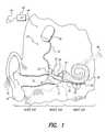
- FIG. 1is a functional schematic diagram of the ear, showing the manner in which an implantable cochlear stimulator and short cochlear electrode placed adjacent the basal region of the cochlea may be used to practice the invention in accordance with one embodiment thereof;
- FIG. 2illustrates a cross-sectional view of the cochlea, showing the three ducts therein, near the region where the blade electrode of the present invention is to be inserted;
- FIGS. 3A and 3Billustrate one embodiment of a blade electrode made in accordance with the present invention
- FIG. 4illustrates a first step of inserting a blade electrode in accordance with the invention, which step involves drilling a “soft cochleostomy” about 1 mm in diameter just to the side of the round window, but without penetrating the spiral ligament membrane;
- FIG. 5illustrates a second step of inserting an electrode in accordance with the invention, which second step involves using a bladed instrument to force the spiral ligament away from the cochlear bone along the lateral wall of the cochlea;
- FIG. 6illustrates the pocket that is created behind the spiral ligament after the second step of the insertion method is carried out
- FIG. 7illustrates a third step of inserting an electrode in accordance with the invention, which third step involves inserting the bladed electrode into the pocket space made behind the spiral ligament;
- FIG. 8schematically depicts the general area, in cross section, where the influence of the electrical stimuli provided through the electrode of the present invention is predominately felt
- FIG. 9shows a cross-sectional representation of the cochlea after the electrode of the present invention has been inserted behind the spiral ligament membrane
- FIG. 10shows a sectional view of the cochlea, depicting the three channels therein, and further depicting a blade electrode array having side fins, in accordance with an alternative embodiment of the invention, positioned under soft tissue of the lateral wall of the cochlea;
- FIG. 11illustrates a top view of the electrode portion of the alternative blade electrode array with side fins shown in FIG. 10, and further illustrates that the electrode array portion has a length L 4 (which is preferably about 10 mm) and a length L 5 (which is preferably about 3 mm);
- FIG. 12illustrates a side view of the alternative blade electrode array with side fins shown in FIG. 10, and further illustrates that the electrode array portion has a thickness L 6 (which is preferably about 1 mm); and
- FIG. 13illustrates the manner in which a soft cochleostomy is made in order to insert the alternative blade electrode array embodiment of FIG. 10, where such cochleostomy is positioned somewhat more on the side of the cochlea so as to allow the fins of the electrode array to be slid between the tissue and bone.
- the present inventionis directed to a cochlear electrode array that does not interfere with the normal functioning of the inner ear.
- One application for the present inventionis for use with a hybrid cochlear stimulation system.
- Another application for the present inventionis for use to supplement the normal hearing processes.
- Yet another applicationis for use of the electrode array, inserted under the spiral ligament membrane at the lateral wall of the cochlea, is to selectively energize the electrodes of the array in order to treat tinnitus.
- the cochlear electrode array of the present inventioncomprises a relatively thin blade electrode array that is inserted underneath the spiral ligament, or soft tissue, at the lateral wall of the cochlea, without actually penetrating into any of the three main ducts that make up the cochlea: the scala tympani, the scala vestibule, or the cochlear duct.
- the blade electrodeis typically implanted into the cochlea through a “soft cochleostomy” operation.
- a soft cochleostomy operationis one wherein a hole is drilled into but not all the way through the bony tissue adjacent the round window. Hence, no penetration occurs into the cochlea ducts, including the scala tympani, the scala vestibuli, and the cochlear duct, and all such ducts remain intact to perform their normal function.
- the blade of a suitable surgical instrumentis inserted into the drilled hole and is used to delaminate the spiral ligament membrane from the bony tissue located at the lateral wall of the cochlea.
- the blade electrode of the inventionis then slid into the opening created by the tissue delamination to a desired depth.
- the desired depthwill typically be a relatively short distance, e.g., 6-12 mm.
- the blade electrodemay be inserted sufficiently deep so as to make up to a 180° turn through the cochlea.
- the blade electrode arrayincorporates thin lips or side fins that extend beyond the body of the carrier of the electrode itself. Such side fins are used to fix the electrode in a groove in the bony recess prepared to hold the electrode.
- the blade electrodecarries one or more mechanical transducers that convert electrical current to mechanical energy, which mechanical energy is then readily coupled directly to the fluid within the cochlea, thereby assisting or aiding the triggering of hair cells that line the inside of the cochlea.
- FIG. 1one embodiment of a representative hybrid cochlear stimulation system is illustrated.
- Such embodimentrelies upon an implantable cochlear stimulator (ICS) 50 to provide direct electrical stimulation of the nerve cells located at the basal end of the cochlea, to thereby enhance the hearing of high frequency sounds; and relies upon the patient's normal hearing processes, e.g., the patient's residual low and mid frequency hearing, to sense low-to-mid frequency sounds.
- ICSimplantable cochlear stimulator
- the outer earincludes the auricle 14 and the ear canal 16 .
- An acoustic pressure wave, or sound wave, represented in FIG. 1 by the short parallel lines 12is collected by the auricle 14 and funneled into the ear canal 16 .
- the “ear drum” 18At the end of the ear cannel 16 is the “ear drum” 18 , or in medical terms, the tympanic membrane 18 .
- the received acoustic wave 12causes the tympanic membrane 18 to vibrate, which vibration is coupled through three tiny bones, known as the ossicles, comprising the malleus (“hammer”) 20 , the incus (“anvil”) 22 and the stapes (“stirrup”) 24 , to the fenestra 30 .
- the ossiclescomprising the malleus (“hammer”) 20 , the incus (“anvil”) 22 and the stapes (“stirrup”) 24 , to the fenestra 30 .
- the fenestracomprises an opening resembling a window.
- the fenestra ovalis, or oval windowis the opening between the middle ear and the scala vestibule of the inner ear. It is closed by a membrane to which the stapes is attached.
- the fenestra rotunda, or round windowis the opening between the scala tympani of the cochlea and the middle ear.
- the round windowis also closed by a membrane, which for purposes of the present application, may be referred to as the round window membrane.
- the function of both the oval window and round windowis represented by the single membrane 30 . In subsequent figures, only the round window is shown, and is represented by a membrane 32 .
- the bones of the middle earserve to filter and amplify the perceived acoustic wave 12 , causing the fenestra membrane 30 to articulate, or vibrate, in response to the acoustic wave 12 .
- Vibration of the membrane 30sets up waves of fluid motion within the fluid contained within the snail-shaped cochlea 36 .
- Such fluid motionin turn, activates tiny hair cells (not shown in FIG. 1) that line the inside of the cochlea 36 .
- Activation of the hair cellscauses appropriate nerve impulses to be transferred through the spiral ganglion cells and auditory nerve 46 to the brain, where they are perceived as sound.
- the spiral ganglion and other cells responsible for the perception of high frequency soundsare generally located at the basal end of the cochlea 36 , i.e., that end of the cochlea closest to the membrane 30 .
- the hair cells in the basal region of the cochleaare ineffective or otherwise damaged to the point where it is usually not possible to activate them.
- an implantable cochlear stimulator (ICS) 50may be implanted near the ear, and a short cochlear electrode array 52 , having a plurality of spaced apart electrodes 54 thereon, is inserted into the cochlea 36 through a soft cochleostomy 31 , adjacent the round window, as explained in more detail below.
- a short cable or lead 51electrically connects the electrode array 52 to the ICS 50 .
- the lead 51is shown passing through the “middle ear” in the functional diagram of FIG. 1, in practice the lead 51 is usually tunneled through tissue that bypasses or goes around the middle ear so as not to interfere in any way with the operation of the ossicles within the middle ear.
- the ICS 50is coupled to a microphone, e.g., an external microphone 40 (although an internal, i.e., implanted, microphone could also be used) that senses sound.
- the microphone signalsare amplified and processed by a suitable speech processor (SP) 42 , which SP may also be external or implanted.
- SPspeech processor
- the speech processorgenerates appropriate control signals that are coupled to the ICS 50 .
- Such couplingmay occur through various means, as are known in the art, but is usually achieved through an inductive coupling link, represented by the arrow 44 , with an external head piece, connected to the speech processor 42 .
- Such linkalso provides a way for power to be coupled into the implanted ICS 50 .
- processor and power sourcemay be implanted, either as an integral part of the ICS 50 or in a separate housing coupled to the ICS. (See, e.g., International Publication No. WO 99/06108, published February 11, 1999, incorporated herein by reference.)
- the speech processor 42functions as a signal processing means for processing the electrical signals received from the microphone 40 and for generating high-frequency control signals therefrom representative of the higher frequency content of the sensed acoustic sounds. These control signals are then coupled to the ICS 50 through the link 44 .
- the ICS 50has means responsive to the high-frequency control signals for selectively generating electrical stimuli and applying the electrical stimuli to the electrode 52 . In this manner, the basal region of the scala tympani 62 (see FIG. 2) of the cochlea 36 is stimulated with electrical stimuli representative of the higher-frequency content of the sensed acoustic sounds.
- the sounds sensed by the microphone 40are processed and filtered to separate out the high frequency sounds. These high frequency sounds are then converted to appropriate electrical stimuli that are selectively applied to the electrode contacts 54 of the electrode array 52 positioned in the basal region of the cochlea. Such electrical stimuli bypass the defective hair cells in the basal region of the cochlea and directly activate the appropriate nerves within the of the spiral ganglion or elsewhere, causing nerve impulses to be transferred to the brain, where they may be perceived as high frequency sounds.
- the other hair cells in the cochleai.e., those in the apical and mid regions of the scala tympani 62 , as well as within other ducts and locations of the cochlea, retain their functionality. That is, these hair cells are able to sense the fluid waves set up by vibrations of the oval window membrane and/or round window membrane corresponding to low-to-mid frequency sounds.
- the patientor user of the hybrid system shown in FIG. 1 primarily senses high frequency sounds through the ICS portion of the system, and primarily senses mid-to-lower frequency sounds through the normal hearing processes of the ear.
- the electrode array 52does not penetrate into the scala tympani 62 or the scala vestibuli 64 of the cochlea 36 .
- these ducts within the cochlearetain their full functionality, and the patient, or user of the hybrid system, is able to utilize his or her normal hearing processes to sense whatever sounds he or she is able to sense with these processes. That is to say, the present invention does not invade the patient's inner ear to the extent that would prevent the inner ear from functioning as best as it is able.
- the benefitis that, for the typical patient who needs a cochlear implant system, the patient is able to hear, whereas prior to the implantation of the cochlear system the patient could not hear, and that portion of the cochlea where the electrode array is inserted did not perform its normal function anyway.
- the present inventionadvantageously allows these normal hearing processes to continue, while still providing the benefits of cochlear stimulation for higher frequency sounds.
- the cochlea 36includes three parallel ducts or channels: the scala tympani 62 , the scala vestibuli 64 , and the cochlear duct 66 .
- Cochlear bony tissue 34resides on one side, the lateral side (the right side as drawn in FIG. 2 ), of the cochlea 36 .
- Spiral ganglion cells 65reside on the other side, the medial side (the left side as drawn in FIG. 2 ), of the cochlea 36 . Separating the three ducts are various membranes and other tissue.
- the Ossicous spiral lamina 67separates the scala vestibuli 64 from the scala tympani 62 .
- the basilar membrane 70separates the scala tympani 62 from the cochlear duct 66 ; and the Vestibular (Reissner's) membrane 69 separates the scala vestibuli 64 from the cochlear duct 66 .
- Many of the hair cells that are vibrated by fluid motion within the cochleaare located in or near the basilar membrane 70 and vestibular membrane 69 . Nerve fibers 68 , embedded within the spiral lamina 67 connect the hair cells with the spiral ganglion cells 65 .
- the spiral ligament membrane 37is located between the lateral side of the spiral tympani 62 and the cochlear bony tissue 34 , and between the lateral side of the cochlear duct 66 and the bony tissue 34 .
- the spiral ligament 37also typically extends around at least a portion of the lateral side of the scala vestibuli 64 and the cochlear bony tissue 34 .
- the present inventionteaches separating, or delaminating, the spiral ligament 37 from the cochlear bony tissue 34 between the points “A” and “B”. Such delamination or separation creates a pocket 39 , best seen in FIG. 6, into which the blade electrode 52 of the present invention may be inserted.
- FIGS. 3A and 3Ba blade electrode array 52 made in accordance with one embodiment of the invention is illustrated.
- FIG. 3Adepicts a front view of such electrode array 52 and
- FIG. 3Bdepicts a side view.
- the blade electrode array 52includes a plurality of spaced-apart electrode contacts 54 that are carried on a suitable flexible carrier 53 .
- Each electrode contact 54is electrically connected to at least one wire 57 that is embedded within the flexible carrier 53 , and within the lead 51 . It is through these wires 57 that the ICS 50 (FIG. 1) provides electrical stimuli to selected ones of the electrode contacts 54 .
- a mechanical or other transducer 54 ′′may also be included on the electrode array in some embodiments, as described below. Such transducer 54 ′′ is not required, but is only optional.
- the flexible carrieris flat and thin, like a blade, with the electrode contacts 54 all residing along one surface, e.g., the medial surface (the surface which faces the medial wall of the cochlea when the array is inserted into the cochlea), of the flat portion of the blade.
- the electrode contactsmay reside on both flat surfaces of the flexible carrier, or they may be bands that encircle the flexible carrier.
- the electrode array 52has a length L 1 of about 10 mm, and has a width L 2 of about 1.2 mm, and has a thickness L 3 of about 0.2 mm. These dimensions are only exemplary, and the actual dimensions may vary as needed. In particular, the length of the array 52 may vary from as short as about 4 mm to as long as about 30 mm, and the number of electrode contacts may vary from as few as one or two to as many as twenty-four or more.
- the preferred method of making the electrode array 52is based on the principle of attaching (by the process of resistance welding) electrode contacts made from precious, biocompatible material (such as platinum or its alloys) to a foil carrier made from a non-toxic but chemically-active metal, such as iron (Fe).
- Resistance weldingadvantageously provides a secure attachment of the electrode material to the foil carrier without causing a deep fusion of the two materials being attached.
- the resulting shallow fusion contactallows clean exposed electrode surface areas to be formed when the foil carrier is eventually chemically etched away.
- Other types of attachmentthat result in shallow fusion of the electrode material and the foil carrier sheet material may also be used in lieu of resistance welding.
- the electrode contactsremain in a desired and stable position allowing easy connecting of a wiring system and subsequent molding of the polymer carrier.
- the metal foil carrieris chemically etched away using a mixture of diluted acids, such as HNO 3 and HCl.
- the precious metal contacts and polymerare immune to the acid and remain in their intact, unaltered shape, and thereby provide the desired electrode array structure.
- FIG. 4illustrates the spiraling scala tympani 62 of the cochlea 36 .
- the round window membrane 32retains the fluid held within the scala tympani 62 of the cochlea from escaping into the middle ear.
- the cochlea 36especially the basal region of the cochlea in the vicinity of the round window 32 , is surrounded by bony tissue 34 . As seen in FIG.
- a first step for making a suitable soft cochleostomy 31is to drill a hole 35 having a diameter D 1 of about 1.0 mm in diameter, on a lateral side of the round window 32 , using a suitable drilling or grinding tool 33 .
- a preferred location for the drilled hole 35is about 1 mm from the closest edge of the round window 32 , but any suitable location may be used.
- the hole 35is drilled as deep as possible without penetrating the spiral ligament membrane 37 . A skilled surgeon is able to recognize when this depth has been reached by the change of color of the bottom of the hole 35 when only the spiral ligament membrane 37 remains.
- a micro-spear 45and/or micro-pick, or equivalent probe tool, is used to delaminate, i.e., separate, the spiral ligament membrane 37 from the cochlear bony tissue 34 . That is, as shown in FIG. 5, the tip of the micro-spear 45 is carefully pressed against the spiral ligament membrane 37 at the bottom of the hole 35 so as to push it away from the cochlear bone tissue 34 , but without punching a hole through the spiral ligament membrane. As a first section of the spiral ligament membrane 37 is pushed away from the bone tissue 34 , the micro-spear 45 is inserted into the space created by the delamination or separation to delaminate or separate additional spiral ligament membrane 37 from the bone tissue 34 .
- the blade electrode array 52is inserted into the pocket 39 , as shown in FIG. 7, so that the electrode contacts 54 face the medial side of the cochlea. When fully inserted, each of the electrode contacts 54 are in contact with the delaminated surface of the spiral ligament membrane 37 .
- the electrode contacts 54are positioned to apply an electrical stimulus that is felt and most effective at stimulating nerves and cells within the circled region 72 shown in FIG. 8 .
- Such circled regionadvantageously includes most of the hair cells and the nerve fibers that attach to such hair cells, and which in turn connect with the spiral ganglion cells 65 .
- FIG. 9shows in cross section the electrode array 52 when inserted between the spiral ligament membrane 37 and the cochlear bony tissue 34 in accordance with the present invention.
- the insertion of the electrode array 52 in the manner describedis minimally invasive. That is, the scala tympani 62 and the scala vestibuli 64 remain essentially undisturbed by the presence of the electrode 52 . Only the cochlear duct 66 may be distorted somewhat when viewed in cross section, by the presence of the electrode array 52 , and such distortion does not prevent the scala tympani 62 and the scala vestibuli 64 from performing their basic function.
- the patientis able to sense sounds through the normal hearing processes that occur within the inner ear to the same degree as he or she could do so before the implant of the electrode array 52 .
- the electrode array 52 , and the ICS 50 to which it is connected, and related componentsmay be used to assist the patient with hearing higher frequency sounds that he or she was previously unable to hear, or to reduce tinnitus (a condition which plagues some patients even though they experience normal hearing).
- FIG. 10a cross-sectional view of the cochlea 36 is illustrated.
- the view of the cochlea shown in FIG. 10is similar to the view shown in FIG. 2, and the same or similar reference numerals are used to denote like parts as are used in connection with FIG. 2 .
- a hole 35 ′is drilled in the bony tissue 34 near the side of the cochlea 36 .
- Such hole 35 ′which may be drilled as a slot, as shown best in FIG. 13, allows a soft cochleostomy 31 ′ to be made that allows access into the space between the spiral ligament 37 and the bony tissue 34 .
- a blade electrode array 52 ′ having side fins 55 made in accordance with an alternative embodiment of the inventionis inserted into the slot hole 35 ′, with the side fins 55 being slid or positioned into the space between the spiral ligament 37 and the bony tissue 34 , thereby holding electrode contacts 54 ′, along one side of the blade electrode array 52 ′, so as to face the cochlea 36 .
- FIGS. 11 and 12show top and side views, respectively, of the blade portion of the electrode array 52 ′.
- side fins 55extend away from opposite sides of the array.
- the length of the blade portionis a distance L 4 , which is preferably about 10 mm.
- the width of the arrayis a distance L 5 , which is preferably about 3 mm, and the thickness is a distance L 6 , which is preferably about 1 mm.
- the electrode contacts 54 ′are spaced apart along one edge of the blade electrode 52 ′. This edge (the edge on which the electrode contacts 54 ′ are located) is the side of the electrode array 52 ′ that faces towards the cochlea when the blade electrode is placed within the soft cochleostomy 31 ′.
- FIG. 13illustrates the use of a drilling tool 33 to create a slot hole 35 ′ in the bony tissue 34 near the cochlea 36 .
- the blade electrode array 52 ′may then be laid into the slot hole, with the electrode contacts 54 ′ facing the cochlea, and with the side fins 55 being slid or positioned into the space between the spiral ligament 37 and the bony tissue 34 .
- the present inventionprovides an electrode array for stimulating nerves and cells of the inner ear, e.g., the cochlea, without interfering with the normal operation of the inner ear, thereby allowing the selective activation of such electrode array to supplement the normal hearing processes that occur within the inner ear, or to treat other symptoms, such as tinnitus.
- the inventionprovides a method of inserting an electrode array into the inner ear without penetrating into the scala tympani or scala vestibuli of the cochlea, thereby permitting the cochlea to perform its normal hearing function without interference.
- the electrode array of the inventionmay be inserted into the inner ear in a minimally invasive manner without interfering with the normal hearing processes that occur within the cochlea, it is noted that the electrode array may also be fitted with one or more mechanical transducers, e.g., elements that convert electrical signals to mechanical energy. Such mechanical transducers may be carried on the flexible carrier 53 in place of one or more of the electrode contacts 54 , e.g., the element 54 ′′ shown in FIG. 3A could be a mechanical transducer and/or a combination mechanical transducer and electrode contact.
- mechanical transducerse.g., elements that convert electrical signals to mechanical energy.
- Such mechanical transducersmay be carried on the flexible carrier 53 in place of one or more of the electrode contacts 54 , e.g., the element 54 ′′ shown in FIG. 3A could be a mechanical transducer and/or a combination mechanical transducer and electrode contact.
- Such mechanical transducersWhen energized, such mechanical transducers impart vibrations to the spiral ligament membrane with which they are in contact, thereby establishing waves of fluid motion within the scala tympani 62 and/or the scala vestibuli 64 and/or the cochlear duct 66 that assist or aid in the hearing process.
- Any suitable mechanical transducer that could be configured for being carried by the flat carrier 53could be used for this purpose, e.g., a piezoelectric film.
- spiral ligament membrane 37applying an electrical stimulus to the spiral ligament membrane 37 causes some of the tissue elements within such membrane to be excited, i.e., to depolarize and contract. Such depolarization and contraction also helps set up wave motions within the fluids contained within the cochlear duct, scala vestibuli and scala tympani. In other words, to a certain extent, the spiral ligament tends to act as its own mechanical transducer, converting the electrical impulses provided through the electrode contacts to mechanical motion that is transferred to the cochlear fluids and that aids in the hearing process.
Landscapes
- Health & Medical Sciences (AREA)
- Otolaryngology (AREA)
- Cardiology (AREA)
- Heart & Thoracic Surgery (AREA)
- Engineering & Computer Science (AREA)
- Biomedical Technology (AREA)
- Nuclear Medicine, Radiotherapy & Molecular Imaging (AREA)
- Radiology & Medical Imaging (AREA)
- Life Sciences & Earth Sciences (AREA)
- Animal Behavior & Ethology (AREA)
- General Health & Medical Sciences (AREA)
- Public Health (AREA)
- Veterinary Medicine (AREA)
- Prostheses (AREA)
Abstract
Description
Claims (14)
Priority Applications (1)
| Application Number | Priority Date | Filing Date | Title |
|---|---|---|---|
| US09/876,882US6549814B1 (en) | 2000-06-09 | 2001-06-07 | Blade electrode array for insertion under soft tissue of lateral wall of cochlea |
Applications Claiming Priority (3)
| Application Number | Priority Date | Filing Date | Title |
|---|---|---|---|
| US21037500P | 2000-06-09 | 2000-06-09 | |
| US26135301P | 2001-01-12 | 2001-01-12 | |
| US09/876,882US6549814B1 (en) | 2000-06-09 | 2001-06-07 | Blade electrode array for insertion under soft tissue of lateral wall of cochlea |
Publications (1)
| Publication Number | Publication Date |
|---|---|
| US6549814B1true US6549814B1 (en) | 2003-04-15 |
Family
ID=27395490
Family Applications (1)
| Application Number | Title | Priority Date | Filing Date |
|---|---|---|---|
| US09/876,882Expired - LifetimeUS6549814B1 (en) | 2000-06-09 | 2001-06-07 | Blade electrode array for insertion under soft tissue of lateral wall of cochlea |
Country Status (1)
| Country | Link |
|---|---|
| US (1) | US6549814B1 (en) |
Cited By (51)
| Publication number | Priority date | Publication date | Assignee | Title |
|---|---|---|---|---|
| US20020144788A1 (en)* | 2001-04-06 | 2002-10-10 | Shortt Frederick John | Automatic applicator for non-adhesive labels |
| US20030074032A1 (en)* | 2001-10-15 | 2003-04-17 | Gliner Bradford Evan | Neural stimulation system and method responsive to collateral neural activity |
| US20030088274A1 (en)* | 2001-09-28 | 2003-05-08 | Vertis Neuroscience, Inc. | Method and apparatus for electrically stimulating cells implanted in the nervous system |
| US20030097161A1 (en)* | 2000-07-13 | 2003-05-22 | Firlik Andrew D. | Methods and apparatus for effectuating a lasting change in a neural-function of a patient |
| US20030125786A1 (en)* | 2000-07-13 | 2003-07-03 | Gliner Bradford Evan | Methods and apparatus for effectuating a lasting change in a neural-function of a patient |
| US20030130706A1 (en)* | 2000-07-13 | 2003-07-10 | Sheffield W. Douglas | Methods and apparatus for effectuating a lasting change in a neural-function of a patient |
| US20040176831A1 (en)* | 2000-07-13 | 2004-09-09 | Gliner Bradford Evan | Apparatuses and systems for applying electrical stimulation to a patient |
| US20040181263A1 (en)* | 2001-03-08 | 2004-09-16 | Jeffrey Balzer | System and method for treating Parkinson's Disease and other movement disorders |
| US20040249422A1 (en)* | 2002-12-10 | 2004-12-09 | Gliner Bradford Evan | Systems and methods for enhancing or optimizing neural stimulation therapy for treating symptoms of movement disorders and/or other neurologic dysfunction |
| US20050021105A1 (en)* | 2000-07-13 | 2005-01-27 | Firlik Andrew D. | Methods and apparatus for effectuating a change in a neural-function of a patient |
| US20050070971A1 (en)* | 2003-08-01 | 2005-03-31 | Brad Fowler | Apparatus and methods for applying neural stimulation to a patient |
| US20050080473A1 (en)* | 2001-04-06 | 2005-04-14 | Peter Gibson | Endosteal electrode |
| US20050274589A1 (en)* | 2004-05-07 | 2005-12-15 | Vanderlande Industries Nederland B.V. | Device for sorting products |
| US20060015153A1 (en)* | 2004-07-15 | 2006-01-19 | Gliner Bradford E | Systems and methods for enhancing or affecting neural stimulation efficiency and/or efficacy |
| US20060079950A1 (en)* | 2001-04-06 | 2006-04-13 | Cochlear Limited | Cochlear endosteal electrode carrier member |
| US20060106430A1 (en)* | 2004-11-12 | 2006-05-18 | Brad Fowler | Electrode configurations for reducing invasiveness and/or enhancing neural stimulation efficacy, and associated methods |
| US20060212094A1 (en)* | 2004-12-31 | 2006-09-21 | Ludwig Moser | Middle ear multi-channel electrode |
| US20060253169A1 (en)* | 2004-11-12 | 2006-11-09 | Northstar Neuroscience, Inc. | Systems and methods for selecting stimulation sites and applying treatment, including treatment of symptoms of Parkinson's disease, other movement disorders, and/or drug side effects |
| US20070005117A1 (en)* | 2005-06-30 | 2007-01-04 | Fritsch Michael H | Extra-cochlear implanted hearing aid device |
| US20070021804A1 (en)* | 2003-05-30 | 2007-01-25 | Maltan Albert A | Stimulation using a microstimulator to treat tinnitus |
| US20070088403A1 (en)* | 2005-10-19 | 2007-04-19 | Allen Wyler | Methods and systems for establishing parameters for neural stimulation |
| US20070135862A1 (en)* | 2005-12-08 | 2007-06-14 | Cochlear Limited | Multimodal auditory fitting |
| US20070135884A1 (en)* | 2005-12-08 | 2007-06-14 | Cochlear Limited | Promoting curvature and maintaining orientation of an electrode carrier member of a stimulating medical device |
| US20070225776A1 (en)* | 2006-03-22 | 2007-09-27 | Fritsch Michael H | Intracochlear Nanotechnology and Perfusion Hearing Aid Device |
| US20080035340A1 (en)* | 2006-08-04 | 2008-02-14 | Halliburton Energy Services, Inc. | Composition and method relating to the prevention and remediation of surfactant gel damage |
| US20080249591A1 (en)* | 2007-04-06 | 2008-10-09 | Northstar Neuroscience, Inc. | Controllers for implantable medical devices, and associated methods |
| US20080300510A1 (en)* | 2006-10-31 | 2008-12-04 | Ao Technology Ag | Method and Device For Measuring the Local Mechanical Resistance of a Porous Body |
| WO2008148825A1 (en)* | 2007-06-06 | 2008-12-11 | Med-El Elektromedizinische Geräte G.M.B.H. | Ear implant and stimulation electrode for an ear implant |
| US7565199B2 (en) | 2002-12-09 | 2009-07-21 | Advanced Neuromodulation Systems, Inc. | Methods for treating and/or collecting information regarding neurological disorders, including language disorders |
| US20090234421A1 (en)* | 2008-03-12 | 2009-09-17 | Nakatomi Hirofumi | Monitoring electrode for monitoring dorsal cochlear nucleus action potentials and monitoring device for monitoring dorsal cochlear nucleus action potentials |
| US20090240099A1 (en)* | 2008-02-29 | 2009-09-24 | Otologics, Llc | Bi-modal cochlea stimulation |
| US20090264962A1 (en)* | 2004-04-02 | 2009-10-22 | Faltys Michael A | Electric and Acoustic Stimulation Fitting Systems and Methods |
| US20100069999A1 (en)* | 2008-09-16 | 2010-03-18 | Med-El Elektromedizinische Geraete Gmbh | Double Branch Cochlear Implant Electrode |
| US20100069997A1 (en)* | 2008-09-16 | 2010-03-18 | Otologics, Llc | Neurostimulation apparatus |
| US20100268313A1 (en)* | 2009-04-16 | 2010-10-21 | Otologics, Llc | Reference electrode apparatus and method for neurostimulation implants |
| US20100331913A1 (en)* | 2005-10-28 | 2010-12-30 | Mann Alfred E | Hybrid multi-function electrode array |
| US20110077698A1 (en)* | 2009-09-28 | 2011-03-31 | Kostas Tsampazis | Method and circuitry for measurement of stimulation current |
| WO2011098144A1 (en) | 2010-02-12 | 2011-08-18 | Advanced Bionics Ag | Hearing aid comprising an intra-cochlear actuator |
| EP2079510A4 (en)* | 2006-09-29 | 2012-05-09 | Cochlear Americas | Elecctrode assembly for a stimulating medical device |
| US8718777B2 (en) | 2002-11-27 | 2014-05-06 | Advanced Neuromodulation Systems, Inc. | Methods and systems for intracranial neurostimulation and/or sensing |
| US8881823B2 (en) | 2011-05-03 | 2014-11-11 | Halliburton Energy Services, Inc. | Environmentally friendly low temperature breaker systems and related methods |
| US8909348B2 (en) | 2010-03-30 | 2014-12-09 | Domestic Legacy Limited Partnership | Cochlear implant stabilization and positioning device |
| US8929991B2 (en) | 2005-10-19 | 2015-01-06 | Advanced Neuromodulation Systems, Inc. | Methods for establishing parameters for neural stimulation, including via performance of working memory tasks, and associated kits |
| US20150066126A1 (en)* | 2013-08-29 | 2015-03-05 | Med-El Elektromedizinische Geraete Gmbh | Fenestration Electrode to Treat Patients with Meniere's Disease |
| US9027647B2 (en) | 2006-08-04 | 2015-05-12 | Halliburton Energy Services, Inc. | Treatment fluids containing a biodegradable chelating agent and methods for use thereof |
| US9120964B2 (en) | 2006-08-04 | 2015-09-01 | Halliburton Energy Services, Inc. | Treatment fluids containing biodegradable chelating agents and methods for use thereof |
| US9127194B2 (en) | 2006-08-04 | 2015-09-08 | Halliburton Energy Services, Inc. | Treatment fluids containing a boron trifluoride complex and methods for use thereof |
| US9334716B2 (en) | 2012-04-12 | 2016-05-10 | Halliburton Energy Services, Inc. | Treatment fluids comprising a hydroxypyridinecarboxylic acid and methods for use thereof |
| US9670399B2 (en) | 2013-03-15 | 2017-06-06 | Halliburton Energy Services, Inc. | Methods for acidizing a subterranean formation using a stabilized microemulsion carrier fluid |
| CN107661571A (en)* | 2017-05-19 | 2018-02-06 | 山东大学 | Sandwich construction flexibility artificial hearing Neural stimulation electrodes and preparation method |
| US10596375B2 (en) | 2017-04-21 | 2020-03-24 | National Chiao Tung University | Cochlear implant device and stimulating method thereof |
Citations (11)
| Publication number | Priority date | Publication date | Assignee | Title |
|---|---|---|---|---|
| US5545219A (en) | 1995-03-30 | 1996-08-13 | Cochlear, Ltd. | Cochlear electrode implant assemblies with positioning system therefor |
| US5649970A (en) | 1995-08-18 | 1997-07-22 | Loeb; Gerald E. | Edge-effect electrodes for inducing spatially controlled distributions of electrical potentials in volume conductive media |
| WO1999006108A1 (en) | 1997-08-01 | 1999-02-11 | Alfred E. Mann Foundation For Scientific Research | Implantable device with improved battery recharging and powering configuration |
| US6038485A (en)* | 1997-06-12 | 2000-03-14 | Axelgaard Manufacturing Co., Ltd. | Current-controlling electrode |
| US6074422A (en) | 1998-04-22 | 2000-06-13 | Epic Biosonics Inc. | Inner ear implant device |
| US6129753A (en) | 1998-03-27 | 2000-10-10 | Advanced Bionics Corporation | Cochlear electrode array with electrode contacts on medial side |
| US6151526A (en) | 1998-04-29 | 2000-11-21 | Advanced Bionics Corporation | Ribbed electrode for cochlear stimulation |
| WO2000069513A1 (en) | 1999-05-14 | 2000-11-23 | Advanced Bionics Corporation | Electrode array for hybrid cochlear stimulator |
| WO2000069512A1 (en) | 1999-05-14 | 2000-11-23 | Advanced Bionics Corporation | Hybrid implantable cochlear stimulator hearing aid system |
| US6163729A (en) | 1998-08-26 | 2000-12-19 | Advanced Bionics Corporation | Method of positioning an implantable cochlear electrode array within a cochlea |
| US6304787B1 (en) | 1998-08-26 | 2001-10-16 | Advanced Bionics Corporation | Cochlear electrode array having current-focusing and tissue-treating features |
- 2001
- 2001-06-07USUS09/876,882patent/US6549814B1/ennot_activeExpired - Lifetime
Patent Citations (11)
| Publication number | Priority date | Publication date | Assignee | Title |
|---|---|---|---|---|
| US5545219A (en) | 1995-03-30 | 1996-08-13 | Cochlear, Ltd. | Cochlear electrode implant assemblies with positioning system therefor |
| US5649970A (en) | 1995-08-18 | 1997-07-22 | Loeb; Gerald E. | Edge-effect electrodes for inducing spatially controlled distributions of electrical potentials in volume conductive media |
| US6038485A (en)* | 1997-06-12 | 2000-03-14 | Axelgaard Manufacturing Co., Ltd. | Current-controlling electrode |
| WO1999006108A1 (en) | 1997-08-01 | 1999-02-11 | Alfred E. Mann Foundation For Scientific Research | Implantable device with improved battery recharging and powering configuration |
| US6129753A (en) | 1998-03-27 | 2000-10-10 | Advanced Bionics Corporation | Cochlear electrode array with electrode contacts on medial side |
| US6074422A (en) | 1998-04-22 | 2000-06-13 | Epic Biosonics Inc. | Inner ear implant device |
| US6151526A (en) | 1998-04-29 | 2000-11-21 | Advanced Bionics Corporation | Ribbed electrode for cochlear stimulation |
| US6163729A (en) | 1998-08-26 | 2000-12-19 | Advanced Bionics Corporation | Method of positioning an implantable cochlear electrode array within a cochlea |
| US6304787B1 (en) | 1998-08-26 | 2001-10-16 | Advanced Bionics Corporation | Cochlear electrode array having current-focusing and tissue-treating features |
| WO2000069513A1 (en) | 1999-05-14 | 2000-11-23 | Advanced Bionics Corporation | Electrode array for hybrid cochlear stimulator |
| WO2000069512A1 (en) | 1999-05-14 | 2000-11-23 | Advanced Bionics Corporation | Hybrid implantable cochlear stimulator hearing aid system |
Cited By (95)
| Publication number | Priority date | Publication date | Assignee | Title |
|---|---|---|---|---|
| US7756584B2 (en) | 2000-07-13 | 2010-07-13 | Advanced Neuromodulation Systems, Inc. | Methods and apparatus for effectuating a lasting change in a neural-function of a patient |
| US8065012B2 (en) | 2000-07-13 | 2011-11-22 | Advanced Neuromodulation Systems, Inc. | Methods and apparatus for effectuating a lasting change in a neural-function of a patient |
| US20060195155A1 (en)* | 2000-07-13 | 2006-08-31 | Northstar Neuroscience, Inc. | Methods and apparatus for effectuating a lasting change in a neural-function of a patient |
| US20030097161A1 (en)* | 2000-07-13 | 2003-05-22 | Firlik Andrew D. | Methods and apparatus for effectuating a lasting change in a neural-function of a patient |
| US20030125786A1 (en)* | 2000-07-13 | 2003-07-03 | Gliner Bradford Evan | Methods and apparatus for effectuating a lasting change in a neural-function of a patient |
| US20030130706A1 (en)* | 2000-07-13 | 2003-07-10 | Sheffield W. Douglas | Methods and apparatus for effectuating a lasting change in a neural-function of a patient |
| US20040176831A1 (en)* | 2000-07-13 | 2004-09-09 | Gliner Bradford Evan | Apparatuses and systems for applying electrical stimulation to a patient |
| US20080161881A1 (en)* | 2000-07-13 | 2008-07-03 | Northstar Neuroscience, Inc. | Methods and apparatus for effectuating a lasting change in a neural-function of a patient |
| US8073546B2 (en) | 2000-07-13 | 2011-12-06 | Advanced Neuromodulation Systems, Inc. | Methods and apparatus for effectuating a lasting change in a neural-function of a patient |
| US20050021105A1 (en)* | 2000-07-13 | 2005-01-27 | Firlik Andrew D. | Methods and apparatus for effectuating a change in a neural-function of a patient |
| US20110004270A1 (en)* | 2000-07-13 | 2011-01-06 | Sheffield W Douglas | Methods and apparatus for effectuating a lasting change in a neural-function of a patient |
| US20110208263A1 (en)* | 2001-03-08 | 2011-08-25 | Jeffrey Balzer | System and method for treating parkinson's disease and other movement disorders |
| US20040181263A1 (en)* | 2001-03-08 | 2004-09-16 | Jeffrey Balzer | System and method for treating Parkinson's Disease and other movement disorders |
| US7299096B2 (en) | 2001-03-08 | 2007-11-20 | Northstar Neuroscience, Inc. | System and method for treating Parkinson's Disease and other movement disorders |
| US20070282416A1 (en)* | 2001-04-06 | 2007-12-06 | Cochlear Limited | Endosteal electrode |
| US20110022147A1 (en)* | 2001-04-06 | 2011-01-27 | Peter Gibson | Method of inserting an endosteal electrode |
| US20060079950A1 (en)* | 2001-04-06 | 2006-04-13 | Cochlear Limited | Cochlear endosteal electrode carrier member |
| US20020144788A1 (en)* | 2001-04-06 | 2002-10-10 | Shortt Frederick John | Automatic applicator for non-adhesive labels |
| US20050080473A1 (en)* | 2001-04-06 | 2005-04-14 | Peter Gibson | Endosteal electrode |
| US7809444B2 (en)* | 2001-04-06 | 2010-10-05 | Cochlear Limited | Endosteal electrode |
| US7962226B2 (en)* | 2001-04-06 | 2011-06-14 | Cochlear Limited | Cochlear endosteal electrode carrier member |
| US20030088274A1 (en)* | 2001-09-28 | 2003-05-08 | Vertis Neuroscience, Inc. | Method and apparatus for electrically stimulating cells implanted in the nervous system |
| US7831305B2 (en) | 2001-10-15 | 2010-11-09 | Advanced Neuromodulation Systems, Inc. | Neural stimulation system and method responsive to collateral neural activity |
| US20030074032A1 (en)* | 2001-10-15 | 2003-04-17 | Gliner Bradford Evan | Neural stimulation system and method responsive to collateral neural activity |
| US8718777B2 (en) | 2002-11-27 | 2014-05-06 | Advanced Neuromodulation Systems, Inc. | Methods and systems for intracranial neurostimulation and/or sensing |
| US7565199B2 (en) | 2002-12-09 | 2009-07-21 | Advanced Neuromodulation Systems, Inc. | Methods for treating and/or collecting information regarding neurological disorders, including language disorders |
| US7353064B2 (en) | 2002-12-10 | 2008-04-01 | Northstar Neuroscience, Inc. | Systems and methods for enhancing or optimizing neural stimulation therapy for treating symptoms of movement disorders and/or other neurologic dysfunction |
| US20040249422A1 (en)* | 2002-12-10 | 2004-12-09 | Gliner Bradford Evan | Systems and methods for enhancing or optimizing neural stimulation therapy for treating symptoms of movement disorders and/or other neurologic dysfunction |
| US20070021804A1 (en)* | 2003-05-30 | 2007-01-25 | Maltan Albert A | Stimulation using a microstimulator to treat tinnitus |
| US20050070971A1 (en)* | 2003-08-01 | 2005-03-31 | Brad Fowler | Apparatus and methods for applying neural stimulation to a patient |
| US7684866B2 (en) | 2003-08-01 | 2010-03-23 | Advanced Neuromodulation Systems, Inc. | Apparatus and methods for applying neural stimulation to a patient |
| US8150527B2 (en) | 2004-04-02 | 2012-04-03 | Advanced Bionics, Llc | Electric and acoustic stimulation fitting systems and methods |
| US20090264962A1 (en)* | 2004-04-02 | 2009-10-22 | Faltys Michael A | Electric and Acoustic Stimulation Fitting Systems and Methods |
| US8155747B2 (en) | 2004-04-02 | 2012-04-10 | Advanced Bionics, Llc | Electric and acoustic stimulation fitting systems and methods |
| US20090264963A1 (en)* | 2004-04-02 | 2009-10-22 | Faltys Michael A | Electric and Acoustic Stimulation Fitting Systems and Methods |
| US20050274589A1 (en)* | 2004-05-07 | 2005-12-15 | Vanderlande Industries Nederland B.V. | Device for sorting products |
| US20060015153A1 (en)* | 2004-07-15 | 2006-01-19 | Gliner Bradford E | Systems and methods for enhancing or affecting neural stimulation efficiency and/or efficacy |
| US7483747B2 (en) | 2004-07-15 | 2009-01-27 | Northstar Neuroscience, Inc. | Systems and methods for enhancing or affecting neural stimulation efficiency and/or efficacy |
| US7983762B2 (en) | 2004-07-15 | 2011-07-19 | Advanced Neuromodulation Systems, Inc. | Systems and methods for enhancing or affecting neural stimulation efficiency and/or efficacy |
| US20090299435A1 (en)* | 2004-07-15 | 2009-12-03 | Northstar Neuroscience, Inc. | Systems and Methods for Enhancing or Affecting Neural Stimulation Efficiency and/or Efficacy |
| US11786729B2 (en) | 2004-07-15 | 2023-10-17 | Advanced Neuromodulation Systems, Inc. | Systems and methods for enhancing or affecting neural stimulation efficiency and/or efficacy |
| US8606361B2 (en) | 2004-07-15 | 2013-12-10 | Advanced Neuromodulation Systems, Inc. | Systems and methods for enhancing or affecting neural stimulation efficiency and/or efficacy |
| US20090076567A1 (en)* | 2004-11-12 | 2009-03-19 | Northstar Neuroscience, Inc. | Electrode Configurations for Reducing Invasiveness and/or Enhancing Neural Stimulation Efficacy, and Associated Methods |
| US20060253171A1 (en)* | 2004-11-12 | 2006-11-09 | Northstar Neuroscience, Inc. | Systems and methods for selecting stimulation sites and applying treatment, including treatment of symptoms of parkinson's disease, other movement disorders, and/or drug side effects |
| US7565200B2 (en) | 2004-11-12 | 2009-07-21 | Advanced Neuromodulation Systems, Inc. | Systems and methods for selecting stimulation sites and applying treatment, including treatment of symptoms of Parkinson's disease, other movement disorders, and/or drug side effects |
| US20060106430A1 (en)* | 2004-11-12 | 2006-05-18 | Brad Fowler | Electrode configurations for reducing invasiveness and/or enhancing neural stimulation efficacy, and associated methods |
| US20060253169A1 (en)* | 2004-11-12 | 2006-11-09 | Northstar Neuroscience, Inc. | Systems and methods for selecting stimulation sites and applying treatment, including treatment of symptoms of Parkinson's disease, other movement disorders, and/or drug side effects |
| US20060253170A1 (en)* | 2004-11-12 | 2006-11-09 | Northstar Neuroscience, Inc. | Systems and methods for selecting stimulation sites and applying treatment, including treatment of symptoms of parkinson's disease, other movement disorders, and/or drug side effects |
| US7917225B2 (en) | 2004-11-12 | 2011-03-29 | Advanced Neuromodulation Systems, Inc. | Systems and methods for selecting stimulation sites and applying treatment, including treatment of symptoms of parkinson's disease, other movement disorders, and/or drug side effects |
| US7742820B2 (en) | 2004-11-12 | 2010-06-22 | Advanced Neuromodulation Systems, Inc. | Systems and methods for selecting stimulation sites and applying treatment, including treatment of symptoms of parkinson's disease, other movement disorders, and/or drug side effects |
| US7908009B2 (en) | 2004-11-12 | 2011-03-15 | Advanced Neuromodulation Systems, Inc. | Systems and methods for selecting stimulation sites and applying treatment, including treatment of symptoms of Parkinson's disease, other movement disorders, and/or drug side effects |
| US7437196B2 (en) | 2004-11-12 | 2008-10-14 | Northstar Neuroscience, Inc. | Systems and methods for selecting stimulation sites and applying treatment, including treatment of symptoms of Parkinson's disease, other movement disorders, and/or drug side effects |
| US20060212094A1 (en)* | 2004-12-31 | 2006-09-21 | Ludwig Moser | Middle ear multi-channel electrode |
| US20070005117A1 (en)* | 2005-06-30 | 2007-01-04 | Fritsch Michael H | Extra-cochlear implanted hearing aid device |
| US8805547B2 (en) | 2005-06-30 | 2014-08-12 | Domestic Legacy Limited Partnership | Extra-cochlear implanted hearing aid device |
| US20070088403A1 (en)* | 2005-10-19 | 2007-04-19 | Allen Wyler | Methods and systems for establishing parameters for neural stimulation |
| US8929991B2 (en) | 2005-10-19 | 2015-01-06 | Advanced Neuromodulation Systems, Inc. | Methods for establishing parameters for neural stimulation, including via performance of working memory tasks, and associated kits |
| US20100331913A1 (en)* | 2005-10-28 | 2010-12-30 | Mann Alfred E | Hybrid multi-function electrode array |
| US8571674B2 (en) | 2005-12-08 | 2013-10-29 | Cochlear Limited | Multimodal auditory fitting |
| US8265765B2 (en) | 2005-12-08 | 2012-09-11 | Cochlear Limited | Multimodal auditory fitting |
| US7937154B2 (en) | 2005-12-08 | 2011-05-03 | Cochlear Limited | Promoting curvature and maintaining orientation of an electrode carrier member of a stimulating medical device |
| US20070135884A1 (en)* | 2005-12-08 | 2007-06-14 | Cochlear Limited | Promoting curvature and maintaining orientation of an electrode carrier member of a stimulating medical device |
| US20070135862A1 (en)* | 2005-12-08 | 2007-06-14 | Cochlear Limited | Multimodal auditory fitting |
| US20070225776A1 (en)* | 2006-03-22 | 2007-09-27 | Fritsch Michael H | Intracochlear Nanotechnology and Perfusion Hearing Aid Device |
| US7650194B2 (en) | 2006-03-22 | 2010-01-19 | Fritsch Michael H | Intracochlear nanotechnology and perfusion hearing aid device |
| US9127194B2 (en) | 2006-08-04 | 2015-09-08 | Halliburton Energy Services, Inc. | Treatment fluids containing a boron trifluoride complex and methods for use thereof |
| US9120964B2 (en) | 2006-08-04 | 2015-09-01 | Halliburton Energy Services, Inc. | Treatment fluids containing biodegradable chelating agents and methods for use thereof |
| US9027647B2 (en) | 2006-08-04 | 2015-05-12 | Halliburton Energy Services, Inc. | Treatment fluids containing a biodegradable chelating agent and methods for use thereof |
| US9074120B2 (en) | 2006-08-04 | 2015-07-07 | Halliburton Energy Services, Inc. | Composition and method relating to the prevention and remediation of surfactant gel damage |
| US20080035340A1 (en)* | 2006-08-04 | 2008-02-14 | Halliburton Energy Services, Inc. | Composition and method relating to the prevention and remediation of surfactant gel damage |
| EP2079510A4 (en)* | 2006-09-29 | 2012-05-09 | Cochlear Americas | Elecctrode assembly for a stimulating medical device |
| US8051720B2 (en)* | 2006-10-31 | 2011-11-08 | Ao Technology Ag | Method and device for measuring the local mechanical resistance of a porous body |
| US20080300510A1 (en)* | 2006-10-31 | 2008-12-04 | Ao Technology Ag | Method and Device For Measuring the Local Mechanical Resistance of a Porous Body |
| US20080249591A1 (en)* | 2007-04-06 | 2008-10-09 | Northstar Neuroscience, Inc. | Controllers for implantable medical devices, and associated methods |
| WO2008148825A1 (en)* | 2007-06-06 | 2008-12-11 | Med-El Elektromedizinische Geräte G.M.B.H. | Ear implant and stimulation electrode for an ear implant |
| US20090240099A1 (en)* | 2008-02-29 | 2009-09-24 | Otologics, Llc | Bi-modal cochlea stimulation |
| US8137286B2 (en) | 2008-03-12 | 2012-03-20 | Nakatomi Hirofumi | Monitoring electrode for monitoring dorsal cochlear nucleus action potentials and monitoring device for monitoring dorsal cochlear nucleus action potentials |
| US20090234421A1 (en)* | 2008-03-12 | 2009-09-17 | Nakatomi Hirofumi | Monitoring electrode for monitoring dorsal cochlear nucleus action potentials and monitoring device for monitoring dorsal cochlear nucleus action potentials |
| US8150528B2 (en)* | 2008-09-16 | 2012-04-03 | Med-El Elektromedizinische Geraete Gmbh | Double branch cochlear implant electrode |
| US20100069999A1 (en)* | 2008-09-16 | 2010-03-18 | Med-El Elektromedizinische Geraete Gmbh | Double Branch Cochlear Implant Electrode |
| US20100069997A1 (en)* | 2008-09-16 | 2010-03-18 | Otologics, Llc | Neurostimulation apparatus |
| US20100268313A1 (en)* | 2009-04-16 | 2010-10-21 | Otologics, Llc | Reference electrode apparatus and method for neurostimulation implants |
| US9044588B2 (en) | 2009-04-16 | 2015-06-02 | Cochlear Limited | Reference electrode apparatus and method for neurostimulation implants |
| US8788032B2 (en) | 2009-09-28 | 2014-07-22 | Cochlear Limited | Method and circuitry for measurement of stimulation current |
| US20110077698A1 (en)* | 2009-09-28 | 2011-03-31 | Kostas Tsampazis | Method and circuitry for measurement of stimulation current |
| WO2011098144A1 (en) | 2010-02-12 | 2011-08-18 | Advanced Bionics Ag | Hearing aid comprising an intra-cochlear actuator |
| US9313587B2 (en) | 2010-02-12 | 2016-04-12 | Advanced Bionics Ag | Hearing aid comprising an intra-cochlear actuator |
| US8909348B2 (en) | 2010-03-30 | 2014-12-09 | Domestic Legacy Limited Partnership | Cochlear implant stabilization and positioning device |
| US8881823B2 (en) | 2011-05-03 | 2014-11-11 | Halliburton Energy Services, Inc. | Environmentally friendly low temperature breaker systems and related methods |
| US9334716B2 (en) | 2012-04-12 | 2016-05-10 | Halliburton Energy Services, Inc. | Treatment fluids comprising a hydroxypyridinecarboxylic acid and methods for use thereof |
| US9670399B2 (en) | 2013-03-15 | 2017-06-06 | Halliburton Energy Services, Inc. | Methods for acidizing a subterranean formation using a stabilized microemulsion carrier fluid |
| US20150066126A1 (en)* | 2013-08-29 | 2015-03-05 | Med-El Elektromedizinische Geraete Gmbh | Fenestration Electrode to Treat Patients with Meniere's Disease |
| US10596375B2 (en) | 2017-04-21 | 2020-03-24 | National Chiao Tung University | Cochlear implant device and stimulating method thereof |
| CN107661571A (en)* | 2017-05-19 | 2018-02-06 | 山东大学 | Sandwich construction flexibility artificial hearing Neural stimulation electrodes and preparation method |
| CN107661571B (en)* | 2017-05-19 | 2024-01-30 | 山东大学 | Flexible auditory nerve stimulating electrode array with multilayer structure |
Similar Documents
| Publication | Publication Date | Title |
|---|---|---|
| US6549814B1 (en) | Blade electrode array for insertion under soft tissue of lateral wall of cochlea | |
| US8249724B2 (en) | Elongate implantable carrier member having an embedded stiffener | |
| US6754537B1 (en) | Hybrid implantable cochlear stimulator hearing aid system | |
| US6070105A (en) | Modiolus-hugging cochlear electrodes | |
| US8452411B2 (en) | Electrode assembly for a stimulating medical device | |
| EP1173044B1 (en) | Implantable system for the rehabilitation of a hearing disorder | |
| US7881811B2 (en) | Flexible electrode assembly having variable pitch electrodes | |
| US7962226B2 (en) | Cochlear endosteal electrode carrier member | |
| US6565503B2 (en) | At least partially implantable system for rehabilitation of hearing disorder | |
| US7809444B2 (en) | Endosteal electrode | |
| US6628991B2 (en) | Minimally-invasive access into the cochlea for electrode insertion and fluid delivery | |
| US20110029031A1 (en) | Bimodal hearing prosthesis | |
| US20070162098A1 (en) | Prosthetic hearing implant electrode assembly having optimal length for atraumatic implantation | |
| US20140358174A1 (en) | Intraneural Implant | |
| US6498954B1 (en) | Apex to base cochlear implant electrode | |
| US6487453B1 (en) | Electrode system for ossified cochlea | |
| EP1185331A1 (en) | Hybrid implantable cochlear stimulator hearing aid system | |
| US20100331913A1 (en) | Hybrid multi-function electrode array | |
| US20180104473A1 (en) | Cochlear electrode array with a flexural inflection point | |
| US20060212094A1 (en) | Middle ear multi-channel electrode | |
| WO2001082848A2 (en) | Minimally-invasive access into the cochlea for electrode insertion and fluid delivery | |
| AU2002244531B2 (en) | Endosteal electrode | |
| AU2006202622A1 (en) | Endosteal electrode | |
| AU2002244531A1 (en) | Endosteal electrode |
Legal Events
| Date | Code | Title | Description |
|---|---|---|---|
| AS | Assignment | Owner name:ADVANCED BLONICS CORPORATION, CALIFORNIA Free format text:ASSIGNMENT OF ASSIGNORS INTEREST;ASSIGNOR:KUZMA, JANUSZ A.;REEL/FRAME:013198/0290 Effective date:20010607 | |
| STCF | Information on status: patent grant | Free format text:PATENTED CASE | |
| FPAY | Fee payment | Year of fee payment:4 | |
| AS | Assignment | Owner name:BOSTON SCIENTIFIC NEUROMODULATION CORPORATION, CAL Free format text:CHANGE OF NAME;ASSIGNOR:ADVANCED BIONICS CORPORATION;REEL/FRAME:020299/0200 Effective date:20071116 | |
| AS | Assignment | Owner name:BOSTON SCIENTIFIC NEUROMODULATION CORPORATION, CAL Free format text:CHANGE OF NAME;ASSIGNOR:ADVANCED BIONICS CORPORATION;REEL/FRAME:020309/0361 Effective date:20071116 | |
| AS | Assignment | Owner name:ADVANCED BIONICS, LLC, CALIFORNIA Free format text:ASSIGNMENT OF ASSIGNORS INTEREST;ASSIGNOR:BOSTON SCIENTIFIC NEUROMODULATION CORPORATION;REEL/FRAME:020340/0713 Effective date:20080107 Owner name:ADVANCED BIONICS, LLC,CALIFORNIA Free format text:ASSIGNMENT OF ASSIGNORS INTEREST;ASSIGNOR:BOSTON SCIENTIFIC NEUROMODULATION CORPORATION;REEL/FRAME:020340/0713 Effective date:20080107 | |
| FPAY | Fee payment | Year of fee payment:8 | |
| FPAY | Fee payment | Year of fee payment:12 | |
| AS | Assignment | Owner name:ADVANCED BIONICS AG, SWITZERLAND Free format text:ASSIGNMENT OF ASSIGNORS INTEREST;ASSIGNOR:ADVANCED BIONICS, LLC;REEL/FRAME:050855/0961 Effective date:20111130 |