US6549774B1 - Digital audio service satellite receiver having switchable operating modes for stationary or mobile use - Google Patents
Digital audio service satellite receiver having switchable operating modes for stationary or mobile useDownload PDFInfo
- Publication number
- US6549774B1 US6549774B1US09/433,864US43386499AUS6549774B1US 6549774 B1US6549774 B1US 6549774B1US 43386499 AUS43386499 AUS 43386499AUS 6549774 B1US6549774 B1US 6549774B1
- Authority
- US
- United States
- Prior art keywords
- receiver
- circuit path
- satellite
- completing
- mobile
- Prior art date
- Legal status (The legal status is an assumption and is not a legal conclusion. Google has not performed a legal analysis and makes no representation as to the accuracy of the status listed.)
- Expired - Fee Related
Links
Images


Classifications
- H—ELECTRICITY
- H04—ELECTRIC COMMUNICATION TECHNIQUE
- H04B—TRANSMISSION
- H04B7/00—Radio transmission systems, i.e. using radiation field
- H04B7/14—Relay systems
- H04B7/15—Active relay systems
- H04B7/185—Space-based or airborne stations; Stations for satellite systems
- H04B7/1853—Satellite systems for providing telephony service to a mobile station, i.e. mobile satellite service
- H04B7/18532—Arrangements for managing transmission, i.e. for transporting data or a signalling message
- H04B7/18534—Arrangements for managing transmission, i.e. for transporting data or a signalling message for enhancing link reliablility, e.g. satellites diversity
- H—ELECTRICITY
- H04—ELECTRIC COMMUNICATION TECHNIQUE
- H04B—TRANSMISSION
- H04B1/00—Details of transmission systems, not covered by a single one of groups H04B3/00 - H04B13/00; Details of transmission systems not characterised by the medium used for transmission
- H04B1/38—Transceivers, i.e. devices in which transmitter and receiver form a structural unit and in which at least one part is used for functions of transmitting and receiving
- H04B1/3827—Portable transceivers
- H04B1/3877—Arrangements for enabling portable transceivers to be used in a fixed position, e.g. cradles or boosters
Definitions
- the present inventionrelates to a method and apparatus for switching a satellite receiver between two operating modes depending on whether the receiver is stationary or mobile.
- Satellite digital audio radio serviceSDARS
- FCCFederal Communications Commission
- the radio receiverscan be stationary receivers, in which case a receiver antenna can be pointed for optimal line of sight (LOS) reception from a satellite.
- LOSline of sight
- the position of the receiver antenna relative to the satellitechanges with mobile receivers (e.g., a receiver that is hand-carried by a user or is mounted in a vehicle), and LOS reception from one satellite is not always available.
- mobile receiversare generally configured to receive broadcast signals from more than one satellite.
- Service outagescan occur in systems which broadcast data, video, audio and other information using radio frequencies. These outages can prevent receivers, and particularly mobile receivers, from receiving the broadcast service altogether, or cause them to receive a signal so degraded that the service is rendered unacceptable. These outages are generally due to physical blockage of transmission paths between the transmitter and receiver (e.g., due to mountainous terrain or long tunnels) and multipath fading and reflection of the transmission path. Satellite broadcast systems can use two transmission channels to provide diversity for mitigating service outages due to multipath, physical blockages and interference in mobile broadcast receivers. Terrestrial repeaters can also be provided to repeat satellite signals in geographic areas where LOS reception is obscured by tall buildings, hills and other obstructions.
- the receiversare configured with first and second receiver arms for receiving signals transmitted from the respective satellites.
- the recovered data streams from the satellitescan be used singly or optimally combined.
- the receivercan also be configured for dual-mode operation to receive both satellite signals and terrestrial signals and to combine or select one of the signals as the receiver output. When the receiver is stationary, only one of the satellite signals is generally required. When the receiver is in a mobile environment, the option of using one or plural received satellite signals for output signal generation is advantageous, particularly when no terrestrial repeater signal is available.
- a satellite receiveris switchable between an operating mode wherein the receiver is capable of generating an output signal using received signals from one or a plurality of satellites, and another operating mode wherein the receiver generates an output signal using signals received from only one satellite.
- the former operating modeis useful when the receiver is operating in a mobile environment (i.e., installed in a vehicle).
- the latter operating modeis useful when the receiver is operating in a fixed environment (e.g., installed at a user's home or otherwise operated at a stationary position).
- the receiveris configured to detect the mode (i.e., fixed or mobile) in which it is operating.
- the receivercomprises at least two receiver circuit arms. Each arm is configured for receiving, downconverting and demodulating a broadcast signal from a selected one of the satellites.
- the receiveris operable to disable at least a portion of one of the two arms when the receiver operating mode corresponding to fixed or stationary use is detected.
- the mobile or fixed modecan be detected depending on whether the receiver is powered on via a DC power supply (e.g., 12 volts or greater from a vehicle battery via the cigarette lighter receptacle or power receptacle) or a residential power supply circuit (e.g., AC power or DC power of 9 volts), respectively.
- a circuitis provided to detect the signal level from the power source and operate a relay which selectively enables and disables components in respective receiver arms.
- the modecan be detected depending on the position of a switch operated by a user.
- the receivercan also be operated in conjunction with a pedestal base which actuates a switch or detector in the receiver.
- the pedestal baseis installed in a vehicle (e.g., on the dashboard of the vehicle).
- the switch or detectoris actuated when the portable receiver is placed on the pedestal.
- the receiveris provided with a power supply sensor for determining if the receiver is operating in a stationary or mobile environment.
- the receiveris provided with an AC power port for connection via a power cord to an AC power outlet.
- the receiveris also provided with a DC power port for connection to a DC power source such as a car battery via the cigarette lighter receptacle or power receptacle.
- One or both of the portscan be provided with a mechanical, magnetic, electromagnetic, semiconductor, electronic or other type of switch or detector that is actuated when the port is connected to its corresponding power source.
- the receivercan also be provided with a motion sensing device.
- the motion sensing devicecan be implemented as a vibration sensor (e.g., for sensing when the receiver is being subjected to vibrations induced by a vehicle engine or contact of the vehicle with a road surface), an encoding compass or heading indicator, an encoding gyroscopic device, a mercury switch device, among other devices.
- a satellite receiveris configured to be portable for use within a vehicle, as well as for stationary use.
- the receiveris provided with a vehicle antenna which can be affixed to a vehicle window, for example.
- the receiveris also provided with a separate antenna for use when the receiver is stationary.
- An operating mode determining devicecan be implemented using a mechanical magnetic, electromagnetic, semiconductor, electronic or other type of switch or detector which is actuated when the stationary antenna is deployed and/or when vehicle antenna is connected to a vehicle antenna port on the receiver.
- FIG. 1illustrates a satellite broadcast system
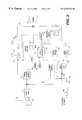
- FIG. 2illustrates a receiver unit constructed in accordance with an embodiment of the present invention
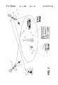
- FIG. 3illustrates an exemplary installation of the receiver unit depicted in FIG. 2 in a vehicle
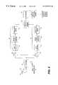
- FIG. 4is a block diagram of a two-arm satellite broadcast receiver for use with the satellite broadcast system depicted in FIG. 1 in accordance with an embodiment of the present invention
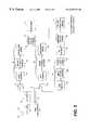
- FIG. 5is a block diagram of a three-arm satellite broadcast receiver for use with the satellite broadcast system depicted in FIG. 1 in accordance with an embodiment of the present invention
- FIG. 6is a schematic diagram of an operating mode detection device in accordance with an embodiment of the present invention.
- FIG. 7is a schematic diagram of an operating mode detection device in accordance with an embodiment of the present invention.
- FIG. 8illustrates an operating mode detection device in accordance with an embodiment of the present invention.
- FIG. 1depicts a satellite broadcast system 10 which comprises at least one geostationary satellite 12 for line of sight (LOS) satellite signal reception at receiver units indicated generally at 14 .
- the satellite broadcast system 10can be used for SDARS, for example.
- Another geostationary satellite 16 at a different orbital positionis provided for diversity purposes.
- One or more terrestrial repeaters 17can be provided to repeat satellite signals from one of the satellites in geographic areas where LOS reception is obscured by tall buildings, hills and other obstructions.
- a receiver unit 14can be configured for stationary use (e.g., on a subscriber's premises), or for mobile use, or both.
- a receiver unit 14 constructed in accordance with the present inventioncomprises at least one satellite antenna 18 for receiving signals from at least one of the satellites 12 and 16 .
- the antenna 18is, for example, a satellite S-band antenna operable at about 2.3 gigaHertz (GHz) for receiving satellite broadcast signals.
- GHzgigaHertz
- the satellite antenna 18is sufficiently broadband to receive first and second satellite channels from the satellites 12 and 16 , respectively, on different frequencies.
- the antenna 18is preferably detachable and is useful for operating the receiver unit 14 in a stationary environment and is directed and pointed for LOS signal reception with a satellite 12 or 16 .
- the antenna 18is preferably connected to a chassis 20 containing other components of the receiver unit 14 .
- the chassis 20is configured for detachable connection to a mobile antenna 26 , that is, an antenna that can be mounted on a vehicle for mobile use.
- the antenna 26 and its associated circuitrye.g., a low noise amplifier
- the antenna 26can be mounted on the roof 27 or rear window 28 of a vehicle 29 , for example.
- a cable 30connects the antenna 26 to the chassis 20 .
- a device 31can be mounted on the exterior of the vehicle's rear window 28 using an adhesive material.
- the device 31supports the antenna 26 and contains any associated circuitry.
- the device 31can be capacitively coupled with another device 32 which is connected to the cable 30 .
- the other device 32can be mounted on the inside of the window 28 opposite the first device 31 using the same adhesive material.
- the antenna 26can be clipped onto a vehicle window as described in the co-pending U.S. patent application Ser. No. 09/317,947, filed May 25, 1999.
- the receiver unit 14can be provided with one or more loudspeakers, indicated generally at 34 , which are either detachable or integral with respect to the chassis 20 .
- the loudspeakersare preferably detachable to allow the receiver unit 14 to be more portable and adaptable for use in a vehicle.
- the receiver unitcan playback received satellite broadcast programs via the AM/FM tuner 36 , antenna 40 and vehicle loudspeakers 38 as described in the above-referenced co-pending U.S. patent application Ser. No. 09/263,207, filed Mar. 5, 1999, and in the above-referenced co-pending U.S. patent application Ser. No.
- the received satellite broadcast programcan be provided to the vehicle tuner 36 and loudspeaker 34 via a wireless or wireline link.
- An exemplary wireless linkcan be implemented by modulating the broadcast program on an open AM or FM frequency channel in the operating range of the tuner 36 .
- An exemplary wireline linkcan be implemented by sending broadcast program signals on a DC power link, which also provides power from the vehicle DC power supply.
- the components in the receiver unit 14 for processing the received satellite broadcast signal for playback on the existing audio system of a vehicleare indicated in FIG. 2 at 42 . These components and the exemplary links are described in the afore-mentioned co-pending applications.
- the receiver unit 14is provided with a microcontroller 44 , a display 46 and a user input device 48 such as a number of buttons and dials.
- the user input device 48can comprise satellite broadcast channel selection buttons, as well as volume control and tuning buttons or dials.
- the microcontroller 44can receive data from a satellite receiver 50 connected to the antenna 18 or 26 . The data is received via an input line 52 and provides information relating to SDARS, which can include, for example, satellite broadcast channel number, artist name, audio program title and data channel information.
- the microcontroller 44can also indicate via the display 46 the signal strength (i.e., RSSI) of satellite or terrestrially repeated SDARS signals, and visual effects (e.g., a dynamic bar graph display corresponding to the output levels of the audio program from the auxiliary audio source), among other displayable information.
- RSSIsignal strength
- visual effectse.g., a dynamic bar graph display corresponding to the output levels of the audio program from the auxiliary audio source
- the receiver unit 14is configured for stationary use by pointing the antenna 18 to the satellite 12 or 16 which provides the best LOS reception and therefore the best satellite signal.
- the microcontroller 44can be programmed to determine the strength of both of the satellite signals via the RSSI data received via the line 52 from the satellite receiver 50 and to select the strongest one of the satellite channels (i.e., receiver arms 54 and 56 ) for reception when operating in the stationary mode.
- the receiver unit 14does not change satellite channels until it is powered down and then powered up again, in which case the operating mode remains unchanged from the previous mode before the receiver unit 14 was powered down.
- a reset button 98can be provided which, when depressed, causes the microcontroller 44 to commence determining the strongest of the two satellite signals to lock onto.
- the microcontroller 44can also be programmed to automatically default to one of the receiver arms 54 and 56 without reference to signal quality when in the stationary mode.
- a toggle button 55can be provided to toggle between the two receiver arms 54 and 56 to allow a user to switch to the other receiver arm when sound quality deteriorates using the active receiver arm.
- the receiver unit 14is operable to dynamically select either one of satellite signals for output, or to combine the two satellite signals. Since terrestrial signals are typically stronger than received satellite signals, output signals from the receiver unit 14 can be generated using only the terrestrial signal in either the stationary or the mobile operating mode if terrestrial repeaters 17 are employed in the satellite broadcast system 10 .
- the satellite receiver 50comprises at least two receiver arms 54 and 56 .
- the satellite receiver 50can be configured with one of two different and exemplary power detection devices for energizing a relay to selectively disable one of the receiver arms. Additional embodiments of the present invention are then described with further reference to FIG. 2 whereby the microcontroller 44 is programmable to receive input signals from one or more operating mode detection devices. The microcontroller 44 is operable in response to these input signals to generate control signals, as indicated at line 53 , for transmission to the satellite receiver 50 .
- the control signalsare operable to disable a receiver arm 54 or 56 in the satellite receiver 50 using a corresponding switching device 58 and 60 , as will now be described in connection with FIG. 4 .
- one of the arms 54 and 56can be disabled when the receiver unit 14 is operating in a stationary environment.
- the receiver arms 54 and 56each receive a signal from a splitter 62 , following signal reception by the antenna 18 or 26 and amplification by a low noise amplifier (LNA) 64 .
- the receiver arm 54comprises a downconverter 66 and an analog-to-digital converter (ADC) 68 .
- a demodulation device 70is provided which can have a demultiplexing function for processing time division multiplexed (TDM) broadcast signals.
- the receiver arm 56comprises a downconverter 78 , an ADC 80 and a demodulation device 82 .
- the data streams from the two arms 54 and 56are combined via a satellite-satellite combiner 74 .
- the output of the combiner 74is processed by a forward error correction (FEC) decoder 76 and an audio or service layer decoder 78 .
- FECforward error correction
- FIG. 5depicts an exemplary satellite receiver 50 having three receiver arms, that is, receiver arms 54 and 56 and a receiver arm 84 for processing signals received via a terrestrial repeater 17 .
- the arm 84receives signals from a received satellite broadcast via the splitter 62 .
- a downconverter 86 and an ADC 88 and a demodulation device 90are provided which operate in substantially the same manner as those described above in connection with the satellite receiver arms 54 and 56 .
- the demodulation device 90can employ a different demodulation method if the modulation method used at the terrestrial repeater 17 differs from that used for the satellite broadcast signals.
- the demodulated streamis processed by an FEC decoder 92 .
- the outputs of the FEC decoder 92 and the FEC decoder 76are combined via the terrestrial-satellite combiner 96 prior to being decoded by the audio or service layer decoder 77 .
- FIGS. 6 and 7, respectively,operate with receiver components which are implemented as an integrated circuit (IC) hereinafter referred to as a channel decoder IC 100 .
- the IC 100is illustrated as having three receiver arms 54 , 56 and 84 , as described above with reference to FIG. 5 .
- the IC 100preferably comprises the corresponding downconverters 66 , 78 and 86 , and the ADCs 68 , 80 and 88 for each receiver arm 54 , 56 and 84 , as indicated by the RF front end devices 102 and 104 for satellite and terrestrial signal processing, respectively.
- the IC 100also comprises the demodulators 70 , 82 and 90 for each receiver arm and the baseband processing devices, as indicated at 106 (e.g., the combiners 74 and 96 , the FEC decoders 76 and 92 , and the service layer decoder 77 ).
- the demodulators 70 , 82 and 90for each receiver arm and the baseband processing devices, as indicated at 106 (e.g., the combiners 74 and 96 , the FEC decoders 76 and 92 , and the service layer decoder 77 ).
- receptacles 108 and 110are provided on the receiver unit 14 .
- the receptacle 108is connected to the coil of a relay 112 , the contacts of which are normally open or in the OFF position. When the contacts are closed, a voltage is applied to the outputs from the relay 112 which are connected to respective ones of the demodulators 70 and 82 .
- an automotive power sourcee.g., a car battery
- the relayis actuated and enables both of the demodulators 70 and 82 .
- a selector switch 114is provided which allows a user to selectively enable only one of the demodulators 70 or 82 and therefore only one of the receiver arms 54 or 56 for satellite signals.
- FIG. 7another embodiment of the present invention is depicted which comprises the IC 100 , the relay 112 and the selector switch 114 described above with reference to FIG. 6; however, only one receptacle 120 is provided in lieu of two independent receptacles 108 and 110 for the supply of automotive or household/battery power to the receiver unit 14 .
- the receptacle 120can be configured to have a number of different types of plugs or sockets to accommodate connections to different types of power sources.
- a single output, however,is connected to a comparator 122 .
- V+is assumed to be 5 volts.
- An automotive power sourcesuch as a car battery is typically 12 volts or more, and household power or consumer battery sources are typically 9 volts.
- the comparator 122is selected to trigger (e.g., go high) when the voltage on its positive input terminal (V+) is greater than the voltage on the negative terminal thereof. If resistors R 1 and R 2 are both 10 kilo-ohms (k ), then V REF is one-half the power source input voltage V IN . Thus, when the input voltage V IN exceeds 10 volts, as for automotive battery power, the V REF value becomes more positive than the V+ value.
- the output signal from the comparator 122that is, the mobile mode enabled signal, is true (e.g., goes high) and therefore energizes the relay 112 to enable the demodulators 70 and 82 in both of the receiver arms 54 and 56 .
- the receiver unit 14is therefore operable in the mobile use mode when connected to an automotive power source.
- the V INis less than 10 volts, as in the stationary mode, the V REF value becomes less than V+ on the comparator 122 . Accordingly, the mobile mode enabled signal is false (e.g., remains low). Only one of the demodulators 70 and 82 can therefore be enabled using the selector switch 114 .
- the receiver unit 14can be implemented differently than with an IC 100 and that receiver arm disabling devices be configured for use in different places along the processing paths of the receiver arms 54 and 56 or other components of the satellite receiver 50 than at the demodulators, as shown in FIGS. 6 and 7.
- FIGS. 4 and 5both depict the exemplary use of switching devices 58 and 60 in the receiver arms 54 and 56 .
- the switching devices 58 and 60can be controlled, for example, by the microcontroller 44 to selectively open or close the connection of the corresponding arm 54 and 56 to the output of the splitter 58 .
- the switching devicescan also be independently operated using a relay, comparator, or other type of device.
- FIGS. 2 and 8Different operating mode detection devices will now be described for providing input signals to the microcontroller 44 or otherwise independently enabling a selected one or both of the satellite receiver arms 54 and 56 in the satellite receiver 50 in accordance with the present invention. These devices will be described in connection with FIGS. 2 and 8. While several of these devices are illustrated for use with one receiver unit 14 in FIG. 2, it is to be understood that the receiver unit 14 need only be equipped with one such device to operate in accordance with the present invention.
- the antenna 18is removably attached to the chassis 20 .
- the chassisis provided with an antenna port 130 for receiving the detachable stationary receiver antenna 18 .
- the antenna port 130is provided with a sensing device 132 such as a mechanical, magnetic, electromagnetic, semiconductor, electronic or other type of switch or detector to detect when the end of the coaxial cable or other conductor connected to the receiver antenna 18 has been inserted into the port 130 .
- the sensing device 132provides an output signal which can be used by the microcontroller 44 or another device (e.g., relay) to disable one of the receiver arms 54 or 56 (e.g., the arm that provides the weakest signal).
- the antenna 26is also preferably removably attached to the chassis 20 at a port 134 .
- the sensing device 132can be provided at the port 134 , as opposed to the port 130 . Accordingly, the receiver unit 12 can be configured to operate in the stationary mode until the end of the coaxial cable or other conductor connected to the antenna 26 is connected to the port 134 . If desired, sensing devices 132 can be provided at both of the antenna ports 130 and 134 .
- the chassis 20is provided with an AC power port 136 and a fixed power cord 138 extending between the AC power port 136 and an AC power outlet 139 .
- the power cord 138is detachable, and a sensing device 140 such as a mechanical, magnetic, electromagnetic, semiconductor, electronic or other type of switch or detector is provided at the port 136 .
- the microcontroller 44is programmed, or another device such as a relay is configured, to operate the receiver unit 14 in a stationary mode (i.e., to disable one of the receiver arms 54 and 56 ) when the sensing device 140 detects the presence of the power cord 138 at the port 136 .
- the chassis 20is also provided with a DC power supply port 142 .
- the receiver unit 14 of the present inventioncan be used in conjunction with a DC power supply cord 144 having an adapter 146 at one end therefor which is configured for insertion in the cigarette lighter receptacle or auxiliary power socket 150 provided in most vehicles. Accordingly, the sensing device 140 can be located proximally with the port 142 to determine if a DC power supply is being used and therefore if the receiver unit 14 is operating in a mobile environment.
- the chassis 20is provided with a manual switch button 152 that can be operated by a user to select an operating mode.
- the button 152can provide an input signal to the microcontroller 44 to disable one of the receiver arms 54 or 56 when activated (e.g., operating one of the switching devices 58 or 60 ).
- the button 152can be used to complete a path between the input of a relay or similar device and a voltage source for actuation. The output of the relay or similar device can then be used as an enabling or disabling signal for one of the satellite receiver arm components.
- the receiver unit 14can also be provided with a motion sensing device 154 having an output connected, for example, to the microcontroller 44 to detect when the receiver unit 14 is being used in a mobile environment.
- the motion sensing device 154can be an accelerometer, a sensor associated with the tachometer of the vehicle or other transit measuring device.
- the motion sensing devicecan be an encoding compass or heading indicator, an encoding gyroscope, a mercury switch, or a vibration sensor selected to have a sensitivity to distinguish between idle and vehicle motion.
- the receiver unit 14is operated in conjunction with a pedestal base 155 that can be installed on the dashboard of a vehicle.
- the receiver unit 14can be provided with a proximity sensing device 156 such as a Hall effect device (HED).
- the basecan be provided with a magnet 158 which actuates the HED 156 when the portable receiver is mounted on the base in the vehicle.
- the microcontroller 44can be programmed to operate the receiver unit 14 in a stationary mode (e.g., using only the arm 54 or 56 which provides the strongest satellite signal output) until actuation of the HED.
- the microcontroller 44then operates the receiver unit 14 in a mobile operating mode until the microcontroller receives an indication that the receiver unit has returned to stationary use.
- the pedestal basecan be configured to provide a circuit path to complete the connection of the antenna 26 to the receiver unit.
- the sensor 134 in FIG. 2can then detect when the antenna 26 is configured to allow use of the receiver unit in a mobile environment using both receiver arms 54 and 56 .
- the mode sensing devicecan be implemented as a device that detects differences in voltage and current characteristics of batteries or other power sources used in the receiver unit and in a vehicle electrical system.
- the receiver unit 14can be provided with a device to dynamically measure the power level of a received satellite signal. If the signal power level is relatively constant, then the receiver unit 14 is determined by the microcontroller 44 to be operating in a stationary environment.
- the receiver unit 14can also be configured to monitor signal strength to determine if a second satellite signal is needed. If the received signal strength drops below a predetermined level, then the non-operating arm 54 or 56 is activated.
- an input signal generated by the vehicle playback interface 42can be provided to the microcontroller 44 to indicate that the receiver unit 14 is operating in a mobile environment.
Landscapes
- Engineering & Computer Science (AREA)
- Physics & Mathematics (AREA)
- Astronomy & Astrophysics (AREA)
- Aviation & Aerospace Engineering (AREA)
- General Physics & Mathematics (AREA)
- Computer Networks & Wireless Communication (AREA)
- Signal Processing (AREA)
- Input Circuits Of Receivers And Coupling Of Receivers And Audio Equipment (AREA)
Abstract
Description
Claims (9)
Priority Applications (1)
| Application Number | Priority Date | Filing Date | Title |
|---|---|---|---|
| US09/433,864US6549774B1 (en) | 1999-11-04 | 1999-11-04 | Digital audio service satellite receiver having switchable operating modes for stationary or mobile use |
Applications Claiming Priority (1)
| Application Number | Priority Date | Filing Date | Title |
|---|---|---|---|
| US09/433,864US6549774B1 (en) | 1999-11-04 | 1999-11-04 | Digital audio service satellite receiver having switchable operating modes for stationary or mobile use |
Publications (1)
| Publication Number | Publication Date |
|---|---|
| US6549774B1true US6549774B1 (en) | 2003-04-15 |
Family
ID=23721835
Family Applications (1)
| Application Number | Title | Priority Date | Filing Date |
|---|---|---|---|
| US09/433,864Expired - Fee RelatedUS6549774B1 (en) | 1999-11-04 | 1999-11-04 | Digital audio service satellite receiver having switchable operating modes for stationary or mobile use |
Country Status (1)
| Country | Link |
|---|---|
| US (1) | US6549774B1 (en) |
Cited By (32)
| Publication number | Priority date | Publication date | Assignee | Title |
|---|---|---|---|---|
| US20020038376A1 (en)* | 2000-09-18 | 2002-03-28 | Halliday Christopher I. | Time shifting over a global communication network |
| US20020151330A1 (en)* | 2001-04-17 | 2002-10-17 | Claude Fouque | System with IC card deactivation before a hardware reset |
| US20020151303A1 (en)* | 2000-01-07 | 2002-10-17 | D'allest Frederic | Telecommunication system with a relay satellite |
| US20040168193A1 (en)* | 2003-02-26 | 2004-08-26 | Kabushiki Kaisha Kenwood | Satellite digital radio broadcast receiver |
| US20040205819A1 (en)* | 2003-04-14 | 2004-10-14 | Ramin Khoini-Poorfard | Integrated multi-tuner satellite receiver architecture and associated method |
| US20040248543A1 (en)* | 2003-03-26 | 2004-12-09 | Atsushi Itsukaichi | Cradle, receiving terminal and receiving method |
| US6836658B1 (en)* | 2000-03-03 | 2004-12-28 | Ems Technologies, Inc. | High data rate satellite communications system and method |
| US20050009577A1 (en)* | 2003-06-27 | 2005-01-13 | Kangas Petri Juhani | Method of monitoring battery characteristics and radio terminal equipment |
| US20050020238A1 (en)* | 2003-07-24 | 2005-01-27 | Eastman Neil S. | Computer based multi-channel radio system and user interface |
| US20050113072A1 (en)* | 2003-11-20 | 2005-05-26 | International Business Machines Corp. | Voicemail messaging via satellite radio |
| US20060094349A1 (en)* | 2004-10-20 | 2006-05-04 | Visteon Global Technologies, Inc. | Dockable portable satellite receiver |
| US20060098371A1 (en)* | 2004-11-08 | 2006-05-11 | Wambsganss Peter M | Temperature sensor for power supply |
| US20060098358A1 (en)* | 2004-11-08 | 2006-05-11 | Wambsganss Peter M | Power supply configured to detect a power source |
| US20060133465A1 (en)* | 2004-12-21 | 2006-06-22 | Dockemeyer Joseph R Jr | Wireless home repeater for satellite radio products |
| US20060276125A1 (en)* | 2005-05-19 | 2006-12-07 | Dibiaso Eric A | Method and system to increase available bandwidth in a time division multiplexing system |
| US20060288395A1 (en)* | 2005-06-20 | 2006-12-21 | Dilorenzo Mark | Media content distribution system and method |
| US20070060092A1 (en)* | 2003-09-29 | 2007-03-15 | Kimmo Laiho | Extension device |
| US20070224962A1 (en)* | 2006-03-08 | 2007-09-27 | Bator Philip M | Integrated digital radio module |
| US20080214101A1 (en)* | 2006-11-28 | 2008-09-04 | Voto Robert M | Apparatus and method for fm wireless vehicle system interface |
| EP1978659A2 (en) | 2007-04-05 | 2008-10-08 | Delphi Technologies, Inc. | System and method for multi-source communications |
| US20080247351A1 (en)* | 2007-01-09 | 2008-10-09 | Viasat, Inc. | Scalable Satellite Deployment |
| US20080311844A1 (en)* | 2007-03-19 | 2008-12-18 | Viasat, Inc. | Multiple Input Receiver In Satellite Communication System |
| US20090025041A1 (en)* | 2005-06-06 | 2009-01-22 | Empcentauri, S.R.O | Change-over switch of external units of fixed aerials for satellite signal receivers |
| US20110034138A1 (en)* | 2007-08-09 | 2011-02-10 | Yeon Joo Park | Tuner and broadcast receiver having the same |
| US20110170005A1 (en)* | 2010-01-14 | 2011-07-14 | Qualcomm Incorporated | Automatic switching between simulcast video signals in a mobile media device |
| US8027634B1 (en) | 2006-05-16 | 2011-09-27 | Eigent Technologies Inc. | RFID system for subscription services with multiple subscribers and/or devices |
| US20110265191A1 (en)* | 2010-04-22 | 2011-10-27 | Russo Leonard E | System and method for placing an electronic apparatus into a protected state in response to environmental data |
| US8432884B1 (en)* | 2011-11-16 | 2013-04-30 | Metropcs Wireless, Inc. | System and method for increased bandwidth efficiency within microwave backhaul of a telecommunication system |
| EP2009816A3 (en)* | 2007-06-29 | 2014-07-02 | Tab Two Limited Liability Company | System and method of communicating multiple carrier waves |
| US20160226609A1 (en)* | 2013-09-13 | 2016-08-04 | Schaidt Innovations Gmbh & Co. Kg | Device and method for reproducing digital receiver signals |
| US9986398B2 (en) | 2013-07-10 | 2018-05-29 | Audi Ag | Radio receiving device |
| US20220215752A1 (en)* | 2019-09-26 | 2022-07-07 | Kyocera Corporation | Roadside apparatus and traffic communication system |
Citations (12)
| Publication number | Priority date | Publication date | Assignee | Title |
|---|---|---|---|---|
| US4422041A (en)* | 1981-07-30 | 1983-12-20 | The United States Of America As Represented By The Secretary Of The Army | Magnet position sensing system |
| US5204981A (en)* | 1990-07-19 | 1993-04-20 | Kokusai Denshin Denwa Kabushiki Kaisha | Interference elimination system |
| US5278863A (en) | 1992-04-10 | 1994-01-11 | Cd Radio Incorporated | Radio frequency broadcasting systems and methods using two low-cost geosynchronous satellites |
| US5301352A (en)* | 1991-07-04 | 1994-04-05 | Sony Corporation | Satellite broadcast receiving system and change-over divider for use in same |
| US5446922A (en)* | 1992-12-21 | 1995-08-29 | Motorola, Inc. | Method and apparatus for switched diversity reception of a radio signal |
| US5485485A (en) | 1992-04-10 | 1996-01-16 | Cd Radio Inc. | Radio frequency broadcasting systems and methods using two low-cost geosynchronous satellites and hemispherical coverage antennas |
| US5592471A (en) | 1995-04-21 | 1997-01-07 | Cd Radio Inc. | Mobile radio receivers using time diversity to avoid service outages in multichannel broadcast transmission systems |
| US5720039A (en) | 1995-09-01 | 1998-02-17 | Cd Radio, Inc. | Satellite multiple access system with distortion cancellation and compression compensation |
| US5794138A (en) | 1997-02-26 | 1998-08-11 | Cd Radio Inc. | Satellite broadcast system receiver |
| US5864579A (en) | 1996-07-25 | 1999-01-26 | Cd Radio Inc. | Digital radio satellite and terrestrial ubiquitous broadcasting system using spread spectrum modulation |
| US6009307A (en)* | 1997-05-13 | 1999-12-28 | Qualcomm Incorporated | Multiple antenna detecting and selecting |
| US6208636B1 (en)* | 1998-05-28 | 2001-03-27 | Northpoint Technology, Ltd. | Apparatus and method for processing signals selected from multiple data streams |
- 1999
- 1999-11-04USUS09/433,864patent/US6549774B1/ennot_activeExpired - Fee Related
Patent Citations (15)
| Publication number | Priority date | Publication date | Assignee | Title |
|---|---|---|---|---|
| US4422041A (en)* | 1981-07-30 | 1983-12-20 | The United States Of America As Represented By The Secretary Of The Army | Magnet position sensing system |
| US5204981A (en)* | 1990-07-19 | 1993-04-20 | Kokusai Denshin Denwa Kabushiki Kaisha | Interference elimination system |
| US5670902A (en)* | 1991-07-04 | 1997-09-23 | Sony Corporation | Satellite broadcast receiving system and change-over divider for use in same |
| US5301352A (en)* | 1991-07-04 | 1994-04-05 | Sony Corporation | Satellite broadcast receiving system and change-over divider for use in same |
| US5485485A (en) | 1992-04-10 | 1996-01-16 | Cd Radio Inc. | Radio frequency broadcasting systems and methods using two low-cost geosynchronous satellites and hemispherical coverage antennas |
| US5319673A (en) | 1992-04-10 | 1994-06-07 | Cd Radio Inc. | Radio frequency broadcasting systems and methods using two low-cost geosynchronous satellites |
| US5278863A (en) | 1992-04-10 | 1994-01-11 | Cd Radio Incorporated | Radio frequency broadcasting systems and methods using two low-cost geosynchronous satellites |
| US5446922A (en)* | 1992-12-21 | 1995-08-29 | Motorola, Inc. | Method and apparatus for switched diversity reception of a radio signal |
| US5592471A (en) | 1995-04-21 | 1997-01-07 | Cd Radio Inc. | Mobile radio receivers using time diversity to avoid service outages in multichannel broadcast transmission systems |
| US5720039A (en) | 1995-09-01 | 1998-02-17 | Cd Radio, Inc. | Satellite multiple access system with distortion cancellation and compression compensation |
| US5745839A (en) | 1995-09-01 | 1998-04-28 | Cd Radio, Inc. | Satellite multiple access system with distortion cancellation and compression compensation |
| US5864579A (en) | 1996-07-25 | 1999-01-26 | Cd Radio Inc. | Digital radio satellite and terrestrial ubiquitous broadcasting system using spread spectrum modulation |
| US5794138A (en) | 1997-02-26 | 1998-08-11 | Cd Radio Inc. | Satellite broadcast system receiver |
| US6009307A (en)* | 1997-05-13 | 1999-12-28 | Qualcomm Incorporated | Multiple antenna detecting and selecting |
| US6208636B1 (en)* | 1998-05-28 | 2001-03-27 | Northpoint Technology, Ltd. | Apparatus and method for processing signals selected from multiple data streams |
Cited By (64)
| Publication number | Priority date | Publication date | Assignee | Title |
|---|---|---|---|---|
| US20020151303A1 (en)* | 2000-01-07 | 2002-10-17 | D'allest Frederic | Telecommunication system with a relay satellite |
| US6836658B1 (en)* | 2000-03-03 | 2004-12-28 | Ems Technologies, Inc. | High data rate satellite communications system and method |
| US20020038376A1 (en)* | 2000-09-18 | 2002-03-28 | Halliday Christopher I. | Time shifting over a global communication network |
| US20080140852A1 (en)* | 2000-09-18 | 2008-06-12 | Halliday Christopher I | Device and method for selection of digital radio channels |
| US20020151330A1 (en)* | 2001-04-17 | 2002-10-17 | Claude Fouque | System with IC card deactivation before a hardware reset |
| US7050830B2 (en)* | 2001-04-17 | 2006-05-23 | Thomson Licensing | System with IC card deactivation |
| US20040168193A1 (en)* | 2003-02-26 | 2004-08-26 | Kabushiki Kaisha Kenwood | Satellite digital radio broadcast receiver |
| US7317894B2 (en)* | 2003-02-26 | 2008-01-08 | Kabushiki Kaisha Kenwood | Satellite digital radio broadcast receiver |
| US20070197264A1 (en)* | 2003-03-26 | 2007-08-23 | Mobile Broadcasting Corporation | Cradle, receiving terminal and receiving method |
| US20040248543A1 (en)* | 2003-03-26 | 2004-12-09 | Atsushi Itsukaichi | Cradle, receiving terminal and receiving method |
| US7356354B2 (en)* | 2003-03-26 | 2008-04-08 | Mobile Broadcasting Corporation | Cradle, receiving terminal and receiving method |
| US20040205820A1 (en)* | 2003-04-14 | 2004-10-14 | Ramin Khoini-Poorfard | Receiver architectures utilizing coarse analog tuning and associated methods |
| US7904040B2 (en) | 2003-04-14 | 2011-03-08 | Silicon Laboratories, Inc. | Receiver architectures utilizing coarse analog tuning and associated methods |
| US7340230B2 (en) | 2003-04-14 | 2008-03-04 | Silicon Laboratories Inc. | Receiver architectures utilizing coarse analog tuning and associated methods |
| US7167694B2 (en) | 2003-04-14 | 2007-01-23 | Silicon Laboratories Inc. | Integrated multi-tuner satellite receiver architecture and associated method |
| US20040205819A1 (en)* | 2003-04-14 | 2004-10-14 | Ramin Khoini-Poorfard | Integrated multi-tuner satellite receiver architecture and associated method |
| US7684834B2 (en)* | 2003-06-27 | 2010-03-23 | Nokia Corporation | Method of monitoring battery characteristics and radio terminal equipment |
| US20050009577A1 (en)* | 2003-06-27 | 2005-01-13 | Kangas Petri Juhani | Method of monitoring battery characteristics and radio terminal equipment |
| US8180275B2 (en)* | 2003-07-24 | 2012-05-15 | Sirius Xm Radio Inc. | Computer based multi-channel radio system and user interface |
| US8571465B2 (en) | 2003-07-24 | 2013-10-29 | Sirius Xm Radio Inc. | Computer based multi-channel radio system and user interface |
| US20050020238A1 (en)* | 2003-07-24 | 2005-01-27 | Eastman Neil S. | Computer based multi-channel radio system and user interface |
| WO2005010713A3 (en)* | 2003-07-24 | 2007-12-27 | Xm Satellite Radio Inc | A computer based multi-channel radio system and user interface |
| US20070060092A1 (en)* | 2003-09-29 | 2007-03-15 | Kimmo Laiho | Extension device |
| US7761055B2 (en)* | 2003-09-29 | 2010-07-20 | Nokia Corporation | Extension device |
| US6996395B2 (en) | 2003-11-20 | 2006-02-07 | International Business Machines Corporation | Voicemail messaging via satellite radio |
| US20050113072A1 (en)* | 2003-11-20 | 2005-05-26 | International Business Machines Corp. | Voicemail messaging via satellite radio |
| US20060094349A1 (en)* | 2004-10-20 | 2006-05-04 | Visteon Global Technologies, Inc. | Dockable portable satellite receiver |
| US7408132B2 (en) | 2004-11-08 | 2008-08-05 | Rrc Power Solutions Gmbh | Temperature sensor for power supply |
| US20060098358A1 (en)* | 2004-11-08 | 2006-05-11 | Wambsganss Peter M | Power supply configured to detect a power source |
| US20060098371A1 (en)* | 2004-11-08 | 2006-05-11 | Wambsganss Peter M | Temperature sensor for power supply |
| US7633998B2 (en) | 2004-12-21 | 2009-12-15 | Delphi Technologies, Inc. | Wireless home repeater for satellite radio products |
| US20060133465A1 (en)* | 2004-12-21 | 2006-06-22 | Dockemeyer Joseph R Jr | Wireless home repeater for satellite radio products |
| US20060276125A1 (en)* | 2005-05-19 | 2006-12-07 | Dibiaso Eric A | Method and system to increase available bandwidth in a time division multiplexing system |
| US7697886B2 (en)* | 2005-05-19 | 2010-04-13 | Delphi Technologies, Inc. | Method and system to increase available bandwidth in a time division multiplexing system |
| US7912420B2 (en)* | 2005-06-06 | 2011-03-22 | Emp-Centauri, S.R.O. | Change-over switch of external units of fixed aerials for satellite signal receivers |
| US20090025041A1 (en)* | 2005-06-06 | 2009-01-22 | Empcentauri, S.R.O | Change-over switch of external units of fixed aerials for satellite signal receivers |
| US8014717B2 (en) | 2005-06-20 | 2011-09-06 | Hotel Digital Network Inc. | Media content distribution system and method |
| US20060288395A1 (en)* | 2005-06-20 | 2006-12-21 | Dilorenzo Mark | Media content distribution system and method |
| US7587167B2 (en)* | 2006-03-08 | 2009-09-08 | Visteon Global Technologies, Inc. | Integrated digital radio module |
| US20070224962A1 (en)* | 2006-03-08 | 2007-09-27 | Bator Philip M | Integrated digital radio module |
| US8027634B1 (en) | 2006-05-16 | 2011-09-27 | Eigent Technologies Inc. | RFID system for subscription services with multiple subscribers and/or devices |
| US20080214101A1 (en)* | 2006-11-28 | 2008-09-04 | Voto Robert M | Apparatus and method for fm wireless vehicle system interface |
| US7773938B2 (en)* | 2006-11-28 | 2010-08-10 | Delphi Technologies, Inc. | Apparatus and method for FM wireless vehicle system interface |
| US8005034B2 (en) | 2007-01-09 | 2011-08-23 | Viasat, Inc. | Scalable satellite deployment |
| US7974571B2 (en) | 2007-01-09 | 2011-07-05 | Viasat, Inc. | Multi-antenna satellite system with wireless interface to vehicle |
| US20080261522A1 (en)* | 2007-01-09 | 2008-10-23 | Dankberg Mark D | Multi-Antenna Satellite System With Wireless Interface To Vehicle |
| US20080247351A1 (en)* | 2007-01-09 | 2008-10-09 | Viasat, Inc. | Scalable Satellite Deployment |
| US20090034448A1 (en)* | 2007-01-09 | 2009-02-05 | Viasat, Inc., A Delaware Corporation | Mimo satellite system |
| US8130693B2 (en) | 2007-01-09 | 2012-03-06 | Viasat, Inc. | MIMO satellite system |
| US20080311844A1 (en)* | 2007-03-19 | 2008-12-18 | Viasat, Inc. | Multiple Input Receiver In Satellite Communication System |
| EP1978659A2 (en) | 2007-04-05 | 2008-10-08 | Delphi Technologies, Inc. | System and method for multi-source communications |
| EP1978659A3 (en)* | 2007-04-05 | 2012-05-09 | Tab Two Limited Liability Company | System and method for multi-source communications |
| EP2009816A3 (en)* | 2007-06-29 | 2014-07-02 | Tab Two Limited Liability Company | System and method of communicating multiple carrier waves |
| US20110034138A1 (en)* | 2007-08-09 | 2011-02-10 | Yeon Joo Park | Tuner and broadcast receiver having the same |
| WO2011088143A3 (en)* | 2010-01-14 | 2011-12-08 | Qualcomm Incorporated | Automatic switching between simulcast video signals in a mobile media device |
| US20110170005A1 (en)* | 2010-01-14 | 2011-07-14 | Qualcomm Incorporated | Automatic switching between simulcast video signals in a mobile media device |
| US8495757B2 (en)* | 2010-04-22 | 2013-07-23 | Hewlett-Packard Development Company, L.P. | System and method for placing an electronic apparatus into a protected state in response to environmental data |
| US20110265191A1 (en)* | 2010-04-22 | 2011-10-27 | Russo Leonard E | System and method for placing an electronic apparatus into a protected state in response to environmental data |
| US8432884B1 (en)* | 2011-11-16 | 2013-04-30 | Metropcs Wireless, Inc. | System and method for increased bandwidth efficiency within microwave backhaul of a telecommunication system |
| US20130121330A1 (en)* | 2011-11-16 | 2013-05-16 | Metropcs Wireless, Inc. | System and method for increased bandwidth efficiency within microwave backhaul of a telecommunication system |
| US9986398B2 (en) | 2013-07-10 | 2018-05-29 | Audi Ag | Radio receiving device |
| US20160226609A1 (en)* | 2013-09-13 | 2016-08-04 | Schaidt Innovations Gmbh & Co. Kg | Device and method for reproducing digital receiver signals |
| US20220215752A1 (en)* | 2019-09-26 | 2022-07-07 | Kyocera Corporation | Roadside apparatus and traffic communication system |
| US11955007B2 (en)* | 2019-09-26 | 2024-04-09 | Kyocera Corporation | Roadside apparatus and traffic communication system |
Similar Documents
| Publication | Publication Date | Title |
|---|---|---|
| US6549774B1 (en) | Digital audio service satellite receiver having switchable operating modes for stationary or mobile use | |
| US6272328B1 (en) | System for providing audio signals from an auxiliary audio source to a radio receiver via a DC power line | |
| CA2366677C (en) | System for providing signals from an auxiliary audio source to a radio receiver using a wireless link | |
| US7542750B2 (en) | Diversity system with identification and evaluation of antenna properties | |
| US20090252204A1 (en) | Receiver system for receiving analog and digital signals | |
| US6961538B2 (en) | Method and apparatus for in-line detection of satellite signal lock | |
| US20060150219A1 (en) | Satellite digital multimedia broadcasting receiver of single tuning type | |
| KR100856343B1 (en) | Apparatus and method for optimizing levels of RF signals based on information stored in memory | |
| US7480483B2 (en) | Mobile broadcast receiving apparatus and control method therefor | |
| US7647019B2 (en) | Apparatus and method for receiving digital multimedia broadcast service in a mobile terminal | |
| JP2008042743A (en) | Radio receiver and antenna changeover control method | |
| US7095757B2 (en) | System and method for optimizing terrestrial signal acquisition in a communication system | |
| KR100649636B1 (en) | Satellite DMG receiver | |
| JP4271087B2 (en) | Receiver | |
| KR100651835B1 (en) | Control device and method used for digital multimedia broadcasting receiver and receiver | |
| EP1198066A2 (en) | Avoidance of interfernce between items of electrial apparatus | |
| KR20050094032A (en) | Diversity system for improving the receiving sensitivity of broadcasting signal and method for controlling the receiving sensitivity of its system | |
| JPH06224810A (en) | Multiplex broadcast receiver device | |
| Heuer et al. | Antenna diversity system for the mobile reception of satellite digital radio | |
| KR20030025603A (en) | Analog and Digital Audio brocasting Composition Receiver and the receiving method | |
| JPH0621858A (en) | Diversity receiver | |
| JPH1188214A (en) | Receiver and reception method by the receiver | |
| KR20090018369A (en) | Antenna Sharing Car Audio System and Control Method | |
| JPH09162790A (en) | On board radio receiver |
Legal Events
| Date | Code | Title | Description |
|---|---|---|---|
| AS | Assignment | Owner name:XM SATELLITE RADIO, INC., DISTRICT OF COLUMBIA Free format text:ASSIGNMENT OF ASSIGNORS INTEREST;ASSIGNORS:TITLEBAUM, JOSEPH L.;ACKER, ROBERT L.;BROWN, DAVID L.;REEL/FRAME:010517/0144 Effective date:19991216 | |
| AS | Assignment | Owner name:BANK OF NEW YORK, THE, NEW YORK Free format text:SECURITY AGREEMENT;ASSIGNOR:XM SATELLITE RADIO INC.;REEL/FRAME:013684/0221 Effective date:20030128 | |
| AS | Assignment | Owner name:THE BANK OF NEW YORK, NEW YORK Free format text:SECURITY INTEREST;ASSIGNOR:XM SATELLITE RADIO INC.;REEL/FRAME:014515/0753 Effective date:20040115 | |
| FPAY | Fee payment | Year of fee payment:4 | |
| AS | Assignment | Owner name:LIBERTY MEDIA CORPORATION, COLORADO Free format text:SECURITY AGREEMENT;ASSIGNOR:XM SATELLITE RADIO INC.;REEL/FRAME:022354/0205 Effective date:20090306 | |
| AS | Assignment | Owner name:JPMORGAN CHASE BANK, N.A., AS COLLATERAL AGENT, NE Free format text:SECURITY AGREEMENT AMENDMENT;ASSIGNOR:XM SATELLITE RADIO INC.;REEL/FRAME:022449/0587 Effective date:20090306 | |
| AS | Assignment | Owner name:XM SATELLITE RADIO INC., NEW YORK Free format text:RELEASE BY SECURED PARTY;ASSIGNOR:LIBERTY MEDIA CORPORATION;REEL/FRAME:022917/0358 Effective date:20090706 | |
| AS | Assignment | Owner name:U.S. BANK NATIONAL ASSOCIATION, NEW YORK Free format text:ASSIGNMENT AND ASSUMPTION OF SECURITY AGREEMENT RECORDED AT REEL/FRAME NO. 22449/0587;ASSIGNOR:JPMORGAN CHASE BANK, N.A.;REEL/FRAME:023003/0092 Effective date:20090630 | |
| AS | Assignment | Owner name:XM SATELLITE RADIO INC., NEW YORK Free format text:TERMINATION AND RELEASE OF SECURITY INTEREST IN PATENT RIGHTS;ASSIGNOR:U.S. BANK NATIONAL ASSOCIATION, AS AGENT;REEL/FRAME:025217/0488 Effective date:20101028 | |
| REMI | Maintenance fee reminder mailed | ||
| AS | Assignment | Owner name:XM SATELLITE RADIO INC., NEW YORK Free format text:TERMINATION AND RELEASE OF SECURITY INTEREST IN PATENT RIGHTS;ASSIGNOR:THE BANK OF NEW YORK MELLON (F/K/A THE BANK OF NEW YORK), AS COLLATERAL AGENT;REEL/FRAME:025406/0888 Effective date:20101129 | |
| AS | Assignment | Owner name:SIRIUS XM RADIO INC., NEW YORK Free format text:MERGER;ASSIGNOR:XM SATELLITE RADIO INC.;REEL/FRAME:025627/0951 Effective date:20110112 | |
| AS | Assignment | Owner name:U.S. BANK NATIONAL ASSOCIATION, AS COLLATERAL AGEN Free format text:SECURITY AGREEMENT;ASSIGNOR:SIRIUS XM RADIO INC.;REEL/FRAME:025643/0502 Effective date:20110112 | |
| LAPS | Lapse for failure to pay maintenance fees | ||
| STCH | Information on status: patent discontinuation | Free format text:PATENT EXPIRED DUE TO NONPAYMENT OF MAINTENANCE FEES UNDER 37 CFR 1.362 | |
| FP | Lapsed due to failure to pay maintenance fee | Effective date:20110415 | |
| AS | Assignment | Owner name:SIRIUS XM RADIO INC., DELAWARE Free format text:TERMINATION AND RELEASE OF SECURITY INTEREST IN PATENT RIGHTS;ASSIGNOR:U.S. BANK NATIONAL ASSOCIATION;REEL/FRAME:028938/0704 Effective date:20120904 |