US6549646B1 - Divide-and-conquer method and system for the detection of lung nodule in radiological images - Google Patents
Divide-and-conquer method and system for the detection of lung nodule in radiological imagesDownload PDFInfo
- Publication number
- US6549646B1 US6549646B1US09/503,840US50384000AUS6549646B1US 6549646 B1US6549646 B1US 6549646B1US 50384000 AUS50384000 AUS 50384000AUS 6549646 B1US6549646 B1US 6549646B1
- Authority
- US
- United States
- Prior art keywords
- zone
- lung
- image
- abnormality
- obscured
- Prior art date
- Legal status (The legal status is an assumption and is not a legal conclusion. Google has not performed a legal analysis and makes no representation as to the accuracy of the status listed.)
- Expired - Lifetime
Links
Images


Classifications
- G—PHYSICS
- G06—COMPUTING OR CALCULATING; COUNTING
- G06T—IMAGE DATA PROCESSING OR GENERATION, IN GENERAL
- G06T7/00—Image analysis
- G06T7/0002—Inspection of images, e.g. flaw detection
- G06T7/0012—Biomedical image inspection
- G—PHYSICS
- G06—COMPUTING OR CALCULATING; COUNTING
- G06V—IMAGE OR VIDEO RECOGNITION OR UNDERSTANDING
- G06V30/00—Character recognition; Recognising digital ink; Document-oriented image-based pattern recognition
- G06V30/10—Character recognition
- G06V30/24—Character recognition characterised by the processing or recognition method
- G06V30/242—Division of the character sequences into groups prior to recognition; Selection of dictionaries
- G06V30/244—Division of the character sequences into groups prior to recognition; Selection of dictionaries using graphical properties, e.g. alphabet type or font
- G—PHYSICS
- G06—COMPUTING OR CALCULATING; COUNTING
- G06T—IMAGE DATA PROCESSING OR GENERATION, IN GENERAL
- G06T2207/00—Indexing scheme for image analysis or image enhancement
- G06T2207/30—Subject of image; Context of image processing
- G06T2207/30004—Biomedical image processing
- G06T2207/30061—Lung
Definitions
- the present inventionrelates to an automated method and system for processing digital radiological images, and more specifically, to a Divide and Conquer (DAC) method and system for the detection of abnormalities, like lung nodules, in radiological chest images using zone-based digital image processing and artificial neural network techniques.
- DACDivide and Conquer
- Lung cancernext to heart disease, is the second highest leading cause of death in the United States.
- Successful detection of early-stage cancer tumorsis able to increase the cure rate.
- Detection and diagnosis of cancerous lung nodules in chest radiographsare among the most important and difficult tasks performed by radiologists. To date, diagnosis in x-ray chest radiographs is the most important diagnostic procedure for the detection of early-stage, clinically occult lung cancer.
- the radiographic miss rate for the detection of lung nodulesis quite high. Observer error, which causes these lesions to be missed, may be due to the camouflaging effect of the surrounding anatomic background on the nodule of interest, or to the subjective and varying decision criteria used by radiologists.
- CADcomputer-aided diagnosis or detection
- Ewa Pietka“Lung Segmentation in Digital Radiographs”, Journal of Digital Imaging , Vol. 7, No. 2 (May), 1994, uses a three-step algorithm involving histogram-dependent thresholding, gradient analysis, and smoothing to identify lung and non-lung regions. The method is developed for use in exposure equalization.
- the purpose of the algorithmis to identify lung zone so that specific computer-aided diagnosis algorithms can be used to detect lung abnormalities including interstitial lung disease, lung nodules, and cardiomegaly.
- the CAD method of Vittitoe et al.is limited to the identified lung zone and ignores the obscured lung regions, such as mediastinum, cardiac, and subdiaphragmatic areas.
- U.S. Pat. No. 4,907,156 to Doi et al.describes a method for detecting and displaying abnormal anatomic regions existing in a digital X-ray image.
- a single projection digital X-ray imageis processed to obtain signal-enhanced image data with a maximum signal-to-noise ratio (SNR) and is also processed to obtain signal-suppressed image data with a suppressed SNR.
- SNRsignal-to-noise ratio
- difference image dataare formed by subtraction of the signal-suppressed image data from the signal-enhanced image data to remove low-frequency structured anatomic background, which is basically the same in both the signal-suppressed and signal-enhanced image data. Once the structured background is removed, feature extraction is performed.
- pixel thresholdingis performed, followed by circularity and/or size testing of contiguous pixels surviving thresholding. Threshold levels are varied, and the effect of varying the threshold on circularity and size is used to detect nodules. Pixel thresholding and contiguous pixel area thresholding are performed for the detection of lung nodules. Clusters of suspected abnormality areas are then detected.
- Lo et al.without mentioning the segmenting of lung zone of the chest image, apply the techniques to the entire chest image to identify suspected abnormality areas.
- the approach used in Lo et al. articledoes not segment the lung zone in the chest image.
- the search and classification of false positivesare not limited to the lung zone but are applied to the whole chest image.
- the methodis based on a difference-image approach and on various feature-extraction techniques, including a growth test, a slope test, and a profile test.
- the aim of the detection schemeis to direct the radiologist's attention to locations in an image that may contain a pulmonary nodule, in order to improve the detection performance of the radiologist.
- U.S. Pat. No. 5,463,548 to Asada et al.describes a system for computer-aided differential diagnosis of diseases and, in particular, computer-aided differential diagnosis using neural networks.
- a first design of the neural networkdistinguishes between a plurality of interstitial lung diseases on the basis of inputted clinical parameters and radiographic information.
- a second designdistinguishes between malignant and benign mammographic cases based upon similar inputted clinical and radiographic information.
- the neural networkswere first trained using a hypothetical database made up of hypothetical cases for each of the interstitial lung diseases and for malignant and benign cases.
- the performance of the neural networkwas evaluated using receiver operating characteristics (ROC) analysis.
- the decision performance of the neural networkwas compared to experienced radiologists and achieved a high performance comparable to that of the experienced radiologists.
- Asada's methodappears to be limited to the detection of lung diseases exclusive of lung cancer, which present different symptoms. Asada's method also does not use a zone-based approach.
- HLNDHybrid Lung Nodule Detection
- the configuration of the HLND systemincludes the following processing phases: (1) pre-processing to enhance the figure-background contrast; (2) quick selection of nodule suspects based upon the most pertinent feature of nodules; and (3) complete feature space determination and neural classification of nodules.
- Chiou et al.classifies suspected nodule areas into different anatomic structures, including rib crossing, rib-vessel crossing, end vessel, vessel cluster, rib edge, vessel, and bone (causing false positive detection). These structures, as well as a true nodule, are used as training classes to develop a neural network classifier. Note that the Chiou et al. method does not include segmentation of the lung zone into different zones or the use of that segmentation in the analytical/diagnostic processes.
- the present inventionfor detection of abnormalities, like lung nodules, in a radiological chest image overcomes the foregoing and other problems associated with the prior art by applying a divide-and-conquer approach.
- the present inventiondivides the lung zone into different zones of similar image characteristics (of both nodule and normal anatomic structure) and conquers the problems of reducing the false positives and increasing the true positives by utilizing different digital image processing techniques and training different neural network classifiers based on the image characteristics of each zone.
- the lung zoneis segmented into different zones, such as spine, clavicle, mediastinum, peripheral lung edge, peripheral lung central, and heart zones.
- the present inventionuses feature extraction and neural networks developed and trained specifically for each zone to finally classify the SAAs to maximize the detection of true nodules within radiological image.
- the findings of the potential SAAs in each zoneare clustered together and used to train neural network classifiers.
- the zonesmay overlap each other.
- the inventiondevelops zone-specific feature extraction algorithms for each of the zones to extract image features of the SAAs located in each particular zone.
- the inventiontrains each zone-specific classifier(s) using the SAA of that zone. Different zone-specific classifiers are trained to have different sensitivities and specificities on each zone.
- the inventionuses SUB-A z (read “SUB-A-SUB-Z”) to validate different classifier performance.
- Some classifierswill have very high specificity (i.e., very low false-positive rate) with relative low sensitivity, while some will have very high sensitivity performance.
- the present inventioncan be implemented in a parallel processing environment. Each zone can be processed independently of each other zone.
- the final output of the systemis produced by a data fusion unit that optimally combines the outputs from different classifiers based on each classifier's sensitivity and specificity performance.
- An embodiment of the inventionincludes a system containing parallel processors that process different zones in parallel and a data fusion unit that combines the output from different classifiers.
- the different classifiersare trained using SAAs of the individual zones.
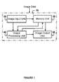
- FIG. 1illustrates a system for implementing a method according to an embodiment of the present invention
- FIG. 2is a schematic diagram of a method according to an embodiment of the present invention.
- FIG. 3is a schematic diagram of an image zoning unit according to an embodiment of the present invention.
- FIG. 4is a schematic diagram of a zone-based image enhancement unit according to an embodiment of the present invention.
- FIG. 5is a schematic diagram of a zone-based suspected abnormality areas selection unit according to an embodiment of the present invention.
- FIG. 6is a schematic diagram of a zone-based feature extraction unit is according to an embodiment of the present invention.
- FIG. 7is a schematic diagram of a zone-based classification unit according to an embodiment of the present invention.
- FIG. 8demonstrates the architecture of a back-propagation trained feed-forward neural network classifier used in the automated method and system according to an embodiment of the present invention
- FIG. 9is a representation of a zone data fusion unit that combines suspect classification scores from different zone classifiers according to an embodiment of the present invention.
- FIG. 10is a representation of the architecture of a parallel processing engine that processes each zone in parallel according to an embodiment of the present invention.
- image data of the anatomic region of interestis entered into the image input unit 20 .
- a video camera, computer radiography (CR) system, digital radiography (DR) system, or a film digitizermay provide such data.
- the data in the image input unit 20is stored for later retrieval and use in the memory unit 30 or sent to image processing unit 40 .
- Any suitable memory unit devicesuch as magnetic tape, computer disk, magnetic-optic (MO) disk, optical laser storage, or the like, can be utilized.
- the method of the present inventionis applied to an image to detect lung nodules within the image.
- the image processing unit 40consists of three stages that correspond to the three main steps of the method of the present invention. Subsequently, the image is sent to the memory unit 30 for storage and/or an image display unit 50 , such as a monitor, a printer, a plotter, a chart recorder, or the like.
- an image display unit 50such as a monitor, a printer, a plotter, a chart recorder, or the like.
- FIG. 2illustrates a schematic diagram of the automated method and system of image processing unit 40 of the present invention.
- an image zoning unit 100digital chest image 95 is processed by the image zoning unit 100 to generate the zoned image 150 .
- the digital chest image 95is divided into non-lung and lung zones in the zoned image 150 .
- the pixels in the non-lung zone of the zoned image 150are discarded and thus not used for further processing.
- the lung zone in the zoned image 150is divided into multiple overlapped zones, such as peripheral edge, diaphragm, clavicle bone, diaphragm, hilum, and peripheral central zones.
- a zone-based image enhancement unit 200utilizes different image enhancement techniques on different zones to generate zone-enhanced image 250 , thereby enhancing potential nodule information in zoned image 150 .
- zone-based suspected abnormality areas selection unit 300contour search and sphere profile matching procedures are performed on each individual zone of the zone-enhanced image 250 to extract image blocks (e.g., 64 ⁇ 64 pixels) of zone-grouped suspected abnormality areas 350 from the digital chest image 95 .
- image blockse.g., 64 ⁇ 64 pixels
- Each image blockcorresponds to a suspected abnormality area at each location on the zone-enhanced image 250 .
- zone-based feature extraction unit 400different feature extraction algorithms are developed for each zone and are employed to extract image features of the zone-grouped suspected abnormality areas 350 .
- Different feature extraction algorithmsare specifically developed by using the zone-grouped suspect nodule areas 350 in each zone to generate zone-grouped suspect features 450 for each suspected abnormality area.
- zone-based classification unit 500different classifiers are developed for each zone and employed to classify zone-grouped suspect features 450 . Different classifiers are specifically trained by the zone-grouped suspect features 450 in each zone to generate suspect a classification score 550 for each suspected abnormality area. Each classifier is trained and cross validated by using the SUB-A z (read as “SUB-A-SUB-Z”) method to train a classifier to have high specificity performance.
- SUB-A zread as “SUB-A-SUB-Z”
- zone-based data fusion unit 600the suspect classification scores 550 associated with each suspected abnormality area from different zones are fused to provide the final suspected abnormality areas 650 .
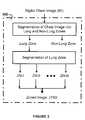
- FIG. 3depicts an embodiment of the image zoning unit 100 of the image processing unit 40 illustrated in FIG. 2 .
- ZN-xrepresents zone x, where x is I, II, III, IV, V, or VI.
- the zoning processhas three major steps: (1) identification of lung zone, (2) identification of non-obscured lung zone, and (3) segmentation of the non-obscured lung zone.
- the preferred embodimentemploys a method proposed by A. Hasegawa, et al. (“A Shift-Invariant Neural Network for the Lung Field Segmentation in Chest Radiography”, 1998) to directly identify the non-obscured and obscured lung zones (i.e., steps (1) and (2)).
- the non-obscured lung zoneis divided into different zones according to geometry distributions and subtleties of abnormalities, such as nodules.
- the spinal cordis the major normal structure in the spine area, and vessels are the major normal structures in the heart area.
- Rib and rib crossingare the major lung structures close to the ribcage.
- the lung zonecan be divided into six zones: (a) zone I—obscured lung zone, (b) zone II—clavicle zone, (c) zone III—peripheral edge zone, (d) zone IV—peripheral central, (e) zone V—hilum zone, and (f) zone VI—diaphragm zone.
- zone Iobscureed lung zone
- zone IIclavicle zone
- zone IIIperipheral edge zone
- zone IVperipheral central
- zone IVperipheral central
- zone Vhilum zone
- zone VIdiaphragm zone.
- FIG. 3Ashows an example of the zoning mask with six zones (I, II, III, IV, V, and VI); each zone is assigned a unique constant gray value. For example, one may use zone I is 100, zone 11 is 200, zone III is 300, zone IV is 400, zone V is 500, and zone VI is 600.
- the dotted linesindicate the overlapped regions of different zone boundaries. The methods used to locate the zones are described as follows:
- the obscured lung zone(zone I) is the area covering the spine, heart, and medastinum.
- the non-obscured lung zone in the chest imageis first extracted using the method proposed by Hasegawa et. al. (“A Shift-Invariant Neural Network for the Lung Field Segmentation in Chest Radiography”, 1998). More than 100 images are used in a back-propagation training method to train a shift-invariant neural network. Following a boundary smoothing method described in the paper, the non-obscured lung zone is identified.
- the obscured lung zoneis obtained by excluding the non-obscured lung zone from the lung zone.
- the zoning mask imageall the pixels in the non-obscured left lung zone are set to 32, all pixels in the non-obscured right lung zone are set to 64, and all pixels in the obscured lung zone are set to 100.
- the clavicle zone(zone II) is the area close to the clavicle or shoulder bone.
- the clavicle zoneis obtained by first locating the locations of the top of the non-obscured left and right lung zones. This can be done by searching vertically for the first pixel that has value of 32 (64) of the left (right) non-obscured lung zone in the mask image.
- the clavicle zoneis the area from the top of the non-obscured left (right) lung extended one fifth of the number of pixels (i.e., one fifth of the distance in pixels between bottom of the lung and top of the lung) from the top of the lung toward the bottom of the left (right) lung. All the pixels located in the clavicle zone are set to 200.
- the peripheral edge zone(zone III) is the area close to the ribcage.
- the peripheral edge zoneis obtained by independently applying an erosion technique on the left and right non-obscured lung zones.
- Each (x, y) point location along the left and right sides of the ribcageis located by using a contour following algorithm (a contour following algorithm is used to trace the boundary of an area, where the edges have pixel values greater than a threshold value.
- a contour following algorithma contour following algorithm is used to trace the boundary of an area, where the edges have pixel values greater than a threshold value.
- Threshold values of 32 and 64are used in the contour following algorithms for extracting the boundary locations of the left and right non-obscured lung zones, respectively.
- an image erosion method using a rectangular structure element to create the peripheral edge zoneis applied.
- the width and height of such a rectangular structure elementmay be, for example, 100 and 1, respectively.
- the erosionis done by centering the rectangular structure element at each ribcage point and, for each pixel of the mask located inside the structure element, replacing the pixel value by the constant value of 300.
- the peripheral central zone(zone IV) is the area between the peripheral edge zone and the hilum zone (to be described next).
- the peripheral central zoneis obtained by applying an erosion technique similar to that used for creating Zone III.
- Two structure elementsone having a width of 360 pixels and the other having a width of 100 pixels, are used in a preferred embodiment. Both structure elements are one pixel in height in this embodiment.
- the erosion techniqueis applied twice on each of the left and right lungs using the two structure elements. On each lung, the two rectangular structure elements are centered at each ribcage point, and two eroded regions are thereby created.
- the overlapped area of the two eroded regionsis defined as the peripheral central zone. All the pixels located inside the peripheral central zone are set to the constant value of 400.
- the hilum zone(zone V) is the area close to the heart.
- the hilum zoneis obtained by applying an erosion technique similar to that used for creating Zone IV except that the heights of the two structure elements (both one pixel in height) are different.
- One structure elementhas width of 560 pixels, while the other structure element has a width of 360 pixels.
- the erosion techniqueis applied twice using the two structure elements by centering the rectangular structure elements at each ribcage point, and two eroded regions are thereby created.
- the overlapped area of the two eroded regionsis defined as the peripheral central zone.
- the hilum zonecan also be obtained by applying the erosion technique along the heart boundary and spine.
- the structure elementhas width of 100 and height of 1 pixel. All the pixels located inside the hilum zone are set to the constant value of 500.
- the diaphragm zone(zone VI) is the area (including obscured and non-obscured lung zone) along the diaphragm.
- the diaphragm zoneis obtained by applying an erosion technique along the diaphragm locations at the bottom of the non-obscured lung zone.
- Image erosion methodsare applied using a rectangular structure element to create the diaphragm zone.
- the structure elementmay have, for example, a width of 1 and a height of 180. The erosion is done by centering the rectangular structure element at each diaphragm point and, for each pixel of the mask located inside the structure element, replacing the pixel value by the constant value of 600.
- FIG. 4depicts an embodiment of a zone-based image enhancement unit 200 of the image processing unit 40 illustrated in FIG. 2 .
- ZN-xrepresents zone x
- EN-xrepresents enhancement algorithm(s) used for zone x
- EZN-xrepresents enhanced zone x, where x is I, II, III, IV, V, or VI.
- a single image enhancement or filtering techniquemay be effective (in enhancing nodule signals) in some areas of the lung zone but less effective in other areas of the lung zone.
- the division of lung zone into further zonesallows the design and development of anatomic and abnormality specific methods for each zone based on each zone's abnormality's subtlety and zone characteristics.
- object-to-background contrast of each zoneis enhanced by a different image enhancement method based on the local image characteristics and abnormality's subtlety of each zone.
- the use of zone-based anatomic specific image enhancement methodscan potentially eliminate a high number of false positives experienced using prior art methods and can potentially increase the detection accuracy.
- the enhancement methods used for each zoneare described as follows:
- a histogram equalization methodis used to enhance the contrast in the obscured lung zone (i.e., zone I).
- the histogram of an imagerepresents the relative frequency of occurrence of the various gray levels in the image.
- Low contrast areaslike the obscured lung zone, have narrow histograms.
- a histogram equalization methodis used to obtain a uniform histogram of the obscured lung zone and hence to improve the contrast of the obscured lung zone.
- the histogram equalized obscured lung zone ( ⁇ *)can be obtained by the following steps:
- Intrepresents the integer (truncation) function and ⁇ min is the smallest positive value of ⁇ .
- Zone IIForm the clavicle zone, the abnormality-to-background contrast is enhanced by removing the clavicle structure by the following steps:
- the Hough transformis used to detect the straight lines in the enhanced clavicle bone and rib (by the Sobel row gradient edge operator) clavicle zone.
- the area of the detected straight lineis replaced by the average pixel value of the neighborhood pixels along the straight line.
- Zone IIIThe peripheral lung edge zone is enhanced by the following three steps:
- the image subtraction methodsubtracts a nodule-suppressed image (e.g., a kernel size of 9 mm for a median filter) from a nodule-enhanced image (e.g., a matched filter of a sphere profile with 9 mm in diameter).
- a nodule-suppressed imagee.g., a kernel size of 9 mm for a median filter
- a nodule-enhanced imagee.g., a matched filter of a sphere profile with 9 mm in diameter.
- the methodis implemented by using two-dimensional spatial image convolution between a filter (match or median) and the image of the peripheral lung edge zone.
- the center pixel in the windowi.e., 9 mm by 9 mm square
- the median of the pixels in the windowi.e., 9 mm by 9 mm square
- the center pixel in the window(again, a 9 mm by 9 mm square) is obtained by convolving the matched filter with the image pixels in the zone.
- Zone IVThe peripheral central zone is enhanced by using an image subtracting method three times (with three sets of median and matched filters) to enhance the abnormality-to-background contrast in the peripheral central zone. Three subtracted images are generated by the three sets of median and matched filters.
- One set of median and matched filtershas sizes of 21 mm and 21 mm in diameter, respectively, one set of median and matched filters has sizes of 15 mm and 15 mm in diameter, respectively, while the third set has sizes of 7 mm and 7 mm for the median and matched filters, respectively.
- Zone VThe hilum zone is enhanced by using an image subtracting method twice (i.e., with two sets of median and matched filters) to enhance the abnormality-to-background contrast in the hilum zone. Two subtracted images are generated by the two sets of median and matched filters. One set of median and matched filters has sizes of 15 mm and 15 mm in diameter, respectively, while the other set has sizes of 9 mm and 9 mm for the median and matched filters, respectively.
- Zone VIThe diaphragm zone is enhanced by an inverse contrast ratio mapping technique.
- the transformgenerates an image where the weak (i.e., low contrast) edges are enhanced.
- u(m,n)represents the pixel value at coordinates (m,n)
- ⁇ (m,n) and ⁇ (m,n)are the local mean and standard deviation of u(m,n) measured over a window W
- Zone-Based Suspect Selection Unit( 300 )
- FIG. 5depicts an embodiment of the zone-based suspect selection unit 300 of the image processing unit 40 illustrated in FIG. 2 .
- SS-xrepresents suspect selection algorithm(s) used for zone x
- SAA-xrepresents suspected abnormality areas in zone x, where x is I, II, III, IV, V, or VI.
- Suspect selection unit 300is used to detect round or nearly round objects in each enhanced zone. This processing stage is primarily based on gray-level contour search and sphere profile matching techniques (Lo, et. al., “Automatic Lung Nodule Detection Using Profile Matching and Back-Propagation Neural Network Techniques”, 1993). Gray-value contour searching is performed to track the gray value edges of a closed boundary. The enclosed area examined by the contour search consists of a suspected abnormality area of a given size, like a 64 ⁇ 64 pixels image block. The image block is first processed via a background correction process, which fits the image block with a two-dimensional second order polynomial function. Each image block is processed with this background correcting process.
- a sphere profile matching techniqueis then used to compute the matching scores between the background-corrected image block of each suspected abnormality area and a set of two-dimensional synthetic sphere profiles of various diameters, such as 9 mm, 13 mm, 17 mm, 21 mm, 25 mm, and 29 mm. Each profile has a third dimension representing normalized intensity.
- the sphere profilesare pre-calculated and stored in the memory unit (Memory Unit 30 in FIG. 1 ). The higher the values of the matching score, the higher the probability that a suspected area contains an abnormality.
- the method for detecting suspected abnormality areas in each zoneis described as follows.
- Step 1Search for pixel values greater than the highest threshold value in the zone.
- a cumulative distribution function(CDF) is generated for each zone of the zone-enhanced image 250 in FIG. 2 .
- CDFcumulative distribution function
- ten different code values for each zoneare selected based on their corresponding probabilities in the CDF of the zone (typically, code values correspond to 95%, 90%, 85%, etc. of CDFs) as the ten threshold values for each zone.
- Step 2Trace the boundary of an area containing pixel values greater than the threshold value.
- a contour following algorithmis used to trace the boundary of an area where the edge has pixel values greater than the threshold value.
- Anil K. Jain, Fundamentals of Digital Image Processingpublished by Prentice-Hall, Inc., 1989, page 358, which is incorporated herein by reference.
- Step 3Find the centroid (or center-of-mass) location of the area.
- Step 4Compute the area and the effective radius of the area.
- the bit quads methodis used to compute the size or area (A 0 ) and perimeter (P 0 ) of the area.
- a 0size or area
- P 0perimeter
- Step 5Make (or retrieve from memory) a two-dimensional synthetic sphere profile having an equivalent radius to the effective radius, i.e., R e .
- Step 6Calculate the matching score between the synthetic sphere profile and the suspected abnormality area.
- S(x,y)is the synthetic nodule block and A(x,y) is the background subtracted image block, which is given by:
- f′(x,y)denotes the background corrected image block and B is the calculated background value.
- Step 7Exclude the area as a potential suspect if the area has effective radius R e larger than the size (such as 20 mm) or R e smaller than the size (such as 8 mm) of the abnormality.
- Step 8Find the most probable case of matching by choosing the greatest match.
- Step 9Mask the area with a value below the threshold value, like 0.
- Step 10Go back to Step 1 and use the next highest threshold value; repeat until all threshold values have been used.
- Different sets of two-dimensional sphere profilesare used in each individual zone to compute the matching score. For example, sphere profiles with small diameters of 9 mm, 13 mm, and 17 mm may be used in Zone I, and sphere profiles with large diameters of 21 mm, 25 mm, and 29 mm may be used in Zone V.
- Zone Isphere profiles with small diameters of 9 mm, 13 mm, and 17 mm
- Zone Vsphere profiles with large diameters of 21 mm, 25 mm, and 29 mm
- the matching score threshold for selecting the suspectsis set to different values for different zones. For example, Zones I and VI have high matching score thresholds while Zone II and III have low matching score thresholds.
- FIG. 6depicts an embodiment of the suspect feature extraction unit 400 of the image processing unit 40 illustrated in FIG. 2 .
- FE-xrepresents feature extraction algorithm(s) used for zone x
- SF-xrepresents suspect features of the SAA in zone x, where x is I, II, III, IV, V, or VI.
- the following methodsare used to extract image features from the image blocks of the suspected abnormality areas (SAAs).
- Zone IFeatures, such as size, circularity, and elongation (or eccentricity), are extracted from each SAA.
- the size featurecan be obtained by the bit quads method as described in Step 4 of the zone-based suspect selection unit 300 .
- E 0R max R min
- R min and R maxare the minimum and maximum distances, respectively, to the boundary from the center of the mass (described in step 3 of the zone-based suspect selection unit 300 ).
- Zone IIGradient features, like amplitude and orientation edge maps, are extracted from each SAA.
- the background corrected imageis then processed with an edge operation, like a 3 ⁇ 3 Sobel edge operator, to obtain two edge maps: amplitude and orientation.
- the orientation anglesare within the range between 0 and 360 degrees, whereas the amplitude varies from 0 to the maximum gray level value, for example, 1023.
- a two-dimensional histogram for both amplitude and orientationis then generated in a step of histogram generation processing; note that different anatomic structures reveal clearly different behaviors in the two-dimensional histogram. It is found that for true nodules the distribution of orientation angles is relatively uniform compared with false positive cases and that the magnitude of gradient amplitude of true nodules is mostly concentrated in the smaller magnitudes.
- Zone IIICircularity (see the definition of C 0 in Zone I), area (see the definition of A 0 in Zone I), and moment invariants are image block features computed for each suspected abnormality area.
- Moment invariants featuresare extracted from each suspected abnormality area.
- Moment invariantsare useful features because they are invariant under linear coordinate transformations, such as translation, scaling, rotation, and reflection. The moments are used as features for an image.
- Zone IVCircularity (see the definition of C 0 in Zone I), size (see the definition of A 0 in Zone I), and amplitude and orientation of the Sobel gradient edge maps (see the description in Zone II) are the features extracted from each suspected abnormality area in Zone IV.
- Zone VNormalized image pixels of the suspected abnormality areas (e.g., 64 ⁇ 64 pixels image block) are used as the features to train a convolution neural network (to be described below in connection with the zone-based classification unit 500 ).
- the normalizationis done by first computing the average pixel value ( ⁇ 0 ) of the 8-connected pixels around the center pixel.
- ⁇is a decaying control parameter and is set to 100.
- Zone VICircularity (see the definition of C 0 in Zone I) and size (see the definition of A 0 in Zone I) are extracted as the features for the suspected abnormality areas in this zone.
- FIG. 7depicts an embodiment of the zone-based classification unit 500 of the image processing unit 40 illustrated in FIG. 2 .
- CA-xrepresents classification method(s) used for zone x
- SCO-xrepresents classifier score for the SAA in zone x, where x is I, II, III, IV, V, or VI.
- the classification stagethe data is first analyzed using background correction, followed by an edge operation, histogram generation, marginal distribution generation, standardization, and neural network classification and integration.
- Zone IIn a preferred embodiment, self-organization feature maps (or learning vector quantization) are used to classify the suspected abnormality areas into two classes: one class representing the abnormality and the other representing false positives.
- the features of size, circularity, and elongationare used as the inputs to the self-organization feature map.
- self-organizing feature mapssee Simon Haykin, Neural Networks: A Comprehensive Foundation , published by Macmillan College Publishing Company, Inc., 1994, page 408-412, which is incorporated herein by reference.
- the feature mapis configured to have one input node and two output nodes.
- the input data to the input nodeis the gray value of each pixel.
- One output nodecorresponds to the true positive class (i.e., abnormality) while the other output node corresponds to the false positive class (i.e., non-abnormality including normal lung structure).
- Euclidean distanceis used as the matching criterion to find the best match in the self-organization learning process.
- Zone IIAmplitude and orientation edge maps are used to train a supervised back-propagation neural network (BP ANN) to classify the abnormalities and the false positives.
- the back propagation neural networkcontains four processing layers.
- the input layerconsists of 64 neurons corresponding to a combination of both amplitude and orientation bins of the marginal distributions (i.e., based on the two-dimensional histograms described above).
- Each set of neurons (amplitude and orientation bins) in the input layerperform a computation based on each individual feature set.
- each set of neuronsworks as an individual classifier.
- Two hidden layerscontain, for example, 128 and 64 neurons, which are chosen as multiples of eight, since the properties of each class are desired to be coded evenly within the network.
- a two-neuron output layeris used to classify either TRUE positive or FALSE positive nodules.
- a sigmoidal transfer functionvarying from ⁇ 1 to +1, is used as an activation function in each neuron.
- a two hidden-layer BP ANN with sigmoidal nonlinearitieshas been demonstrated theoretically and experimentally to classify any shape of decision regions and to approximate complex nonlinear functions.
- the data set of image blocks containing the true abnormalities and normal lung structures in this zoneare first separated into a training set and a test set.
- the BP ANNlearns from the training set presented to it during a learning phase (weight adaptation) until most of the training cases are learned properly.
- the trained networkis then applied to the test data set.
- the BP ANNlearns from the training data set presented to it during the learning phase (weight adaptation phase), the training samples need to be distributed equally among classes. By so doing, the BP ANN will not be biased toward any particular result class (in this case, TRUE nodule class and FALSE nodule class).
- TRUE nodule classand FALSE nodule class.
- the TRUE nodule samplewas replicated several times, and FALSE nodule samples were duplicated based upon the statistical properties of the training set such that there were similar amounts of TRUE and FALSE positive samples in the training sample set.
- the training processis stopped when the learning achieves the maximum SUB-A z (read as SUB-A-SUB-Z) area under the receiver operating characteristic (ROC) curve.
- This methodis called the cross-validated by SUB-A z (read as SUB-A-SUB-Z) or partial ROC area index.
- Cross-validationis a widely used method to determine the stopping point of a training process (i.e., training is stopped when the “best” set of weights are obtained during the learning process).
- the data setis randomly divided into two sets, one training set and one testing set.
- the training setis further divided into two subsets: (a) a subset used for training the classifier and (b) a subset for evaluation of the performance of the trained classifier (i.e., validation of generalization performance); the valuation subset is typically ten to twenty percent of the training set.
- a subset used for training the classifieri.e., validation of generalization performance
- the valuation subsetis typically ten to twenty percent of the training set.
- the cross-validationis done by finding the minimum mean-square error (on the cross-validation subset) on the cross-validation generalization curve at every training epoch.
- the SUB-A zis used to cross-validate the training process, and the training is stopped when the SUB-A z achieves a maximum.
- ROC analysisis a widely used method of evaluating diagnostic performance. It provides a description of trade-offs between sensitivity and specificity.
- the area under the ROC curvei.e., A z
- the area under the ROC curveis normally used as the performance index described by an entire ROC curve.
- Yulei Jiang, et. al.“A Receiver Operating Characteristic Partial Area Index for Highly Sensitive Diagnostic Test”, Radiology , Vol. 201, No. 3, 1996, pages 745-750, which is incorporated herein by reference.
- entire data setsare then applied to the network to generate output values ranging from ⁇ 1 to +1 at each neuron, representing the possibility of the occurrence of TRUE or FALSE nodules.
- Zone IIIWe use the circularity, size, and moment invariants (the seven second- and third-order moments discussed above) features to train an error back-propagation neural network.
- the back propagation neural networkcontains four processing layers.
- the input layerconsists of nine neurons corresponding to combination circularity, size, and seven moment invariants.
- Two hidden layerscontain, for example, 36 and 18 neurons, respectively.
- Finally a one-neuron output layeris used to classify either TRUE positive or FALSE positive (abnormality).
- a sigmoidal transfer functionvarying from ⁇ 1 to +1, is used as an activation function in each neuron.
- the data set of image blocks of suspected abnormality areasis first separated into a training set and a test set.
- the BP ANNlearns from the training set presented to it during a learning phase (weight adaptation) until most of the training cases are learned properly (this is the so called back-propagation learning algorithm).
- the trained networkis then applied to the test data set. Approximately 50% of the data set is used as training examples, and the rest is used as the test set. Since the BP ANN learns from the training data set presented to it during the learning phase (weight adaptation phase), the training samples need to be distributed equally among classes.
- the BP ANNwill not be biased toward any result class(es) (in this case, TRUE nodule class and FALSE nodule class).
- TRUE nodule class and FALSE nodule classresult class(es)
- TRUE nodule class and FALSE nodule classresult class(es)
- a TRUE nodule samplewas replicated several times, and FALSE nodule samples were duplicated based upon the statistical properties of the training set such that similar amounts of TRUE and FALSE positive samples were present in the training sample set.
- the training processis cross-validated such that the learning is stopped when the SUB-A z area in the high specificity region achieves a maximum.
- entire data setsare then applied to the network to generate output values ranging from ⁇ 1 to +1 at each neuron, representing the possibility of the occurrence of TRUE or FALSE nodules.
- Zone IVThe features of circularity, size, and amplitude and orientation information are used as the input features to train a supervised back-propagation neural network.
- the back propagation neural networkcontains four processing layers.
- the input layerconsists of 66 neurons corresponding to a combination of circularity, size, and both amplitude and orientation bins of the marginal distributions.
- Each two sets of (amplitude and orientation bins) neurons in the input layerperform the computation based on each individual feature set. Hence, each set of neurons works as an individual classifier.
- Two hidden layerscontain, for example, 132 and 66 neurons.
- a two-neuron output layeris used to classify either TRUE positive or FALSE positive nodules.
- a sigmoid transfer functionvarying from ⁇ 1 to +1, is used as an activation function in each neuron.
- the data set of image blocks in this zoneis first separated into a training set and a test set.
- the classifieris trained by the back-propagation learning algorithm. Approximately 40% of the data set is typically used as training examples, and the rest are used as the test set. Since a BP ANN learns from the training data set presented to it during the learning phase (weight adaptation phase), the training samples need to be distributed equally among classes. By so doing, the BP ANN will not be biased toward any result class(es) (in this case, TRUE nodule class and FALSE nodule class).
- a TRUE nodule samplewas replicated several times, and FALSE nodule samples were duplicated based upon the statistical properties of the training set such that similar amounts of TRUE and FALSE positive samples were in the training sample set.
- the neural networkis trained and cross-validated to have high specificity by using the SUB-A z method (see the description in Zone III). After training of the neural network is complete, entire data sets are then applied to the network to generate output values ranging from ⁇ 1 to +1 at each neuron, representing the possibility of the occurrence of TRUE or FALSE nodules.
- U.S. patent application Ser. No. 08/597,736submitted by M. Yeh, et. al., “Method and System for the Detection of Lung Nodule in Radiographical Images Using Digital Image Processing and Artificial Neural Network”, which is incorporated herein by reference.
- Zone VThe normalized image pixels of the suspected abnormality areas are used to train a convolution neural network.
- the convolution neural networkhas one input layer, one hidden layer, and one output layer.
- the input layerconsists of the pixels of the normalized image block (64 ⁇ 64 pixels), and the output layer consists of one output neuron.
- the hidden layeris composed of 10 groups of 60 by 60 neurons arranged as n independent 60 by 60 feature maps, where 60 is equal to 64 ⁇ 5+1 and the convolution kernel corresponds to a 5 ⁇ 5 area.
- Each hidden neuron in the feature map in the hidden layertakes input on a 5 ⁇ 5 neighborhood of the input image block. For neurons in the same feature map that are one neuron apart, their receptive fields in the input layer are one pixel apart.
- Each neuron in the same feature mapis constrained to have the same set of 25 weights and to perform the same operation on the corresponding part of the input image.
- the convolution neural networkis trained by using the back-propagation learning algorithm and is cross validated by the SUB-A z method (see the description in Zone III).
- the convolution neural networkis trained to have high specificity.
- Jyh-Shyan Lin, et. al.“Differentiation Between Nodules and End-On Vessels Using a Convolution Neural Network Architecture”, Journal of Digital Imaging , Vol. 8, No. 3, 1995, page 132-141, which is incorporated herein by reference.
- Zone VIRule-based classification is used to classify the suspected abnormality areas based on their circularity (see the definition of C 0 in zone I in Zone-Based Suspect Feature Extraction Unit 400 ) and effective radius (see R e in step 4 in the Zone-Based Suspect Selection Unit 300 ) features.
- the distribution of the circularity and sizeis analyzed for abnormalities and false positives.
- a thresholdis selected for each of the circularity and the size.
- the rules used to select a potential abnormality, e.g., noduleare as follows:
- the threshold valueis determined based on the sensitivity and specificity performance of each zone-specific classifier.
- FIG. 8depicts an embodiment of the system shown in FIG. 7, showing detail of some of the internal structures within the parallel processing structure 525 .
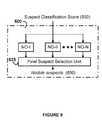
- FIG. 9depicts an embodiment of the zone-based data fusion unit 600 of the image processing unit 40 illustrated in FIG. 2 .
- the suspect classification scores 550 generated by different classifiers of different zonesare normalized by the zone-based score normalization units indicated as NO-I, NO-II, etc.
- the classification score for each suspect in the same zoneis normalized by the maximum score in that zone.
- S iis the classification score for the ith suspect in zone M
- subscript iindicate the ith suspect
- MAX ⁇ . ⁇is the maximum value in the set.
- the normalized scores for the suspects of different zonesare fed into a final suspect selection unit 625 . Based on the normalized score, the final suspect selection unit 625 selects the suspects as the final suspects using the following rules:
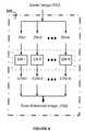
- FIG. 10illustrates a schematic diagram of an embodiment of a parallel processing implementation of the image processing unit 40 illustrated in FIG. 2 .
- the automated system and method for lung nodule detectionhas been implemented in a multiple processor environment.
- the divide-and-conquer methodcan be implemented in pipelining form or in parallel based on the processing speed and throughput of each processor.
- one processormay be processing Zone I while the other processing elements are processing other zones. The results from different zones will be combined based on throughput of each processing element.
Landscapes
- Engineering & Computer Science (AREA)
- Theoretical Computer Science (AREA)
- Computer Vision & Pattern Recognition (AREA)
- Physics & Mathematics (AREA)
- General Physics & Mathematics (AREA)
- Health & Medical Sciences (AREA)
- Multimedia (AREA)
- General Health & Medical Sciences (AREA)
- Medical Informatics (AREA)
- Nuclear Medicine, Radiotherapy & Molecular Imaging (AREA)
- Radiology & Medical Imaging (AREA)
- Quality & Reliability (AREA)
- Apparatus For Radiation Diagnosis (AREA)
- Image Processing (AREA)
Abstract
Description


Claims (102)


Priority Applications (1)
| Application Number | Priority Date | Filing Date | Title |
|---|---|---|---|
| US09/503,840US6549646B1 (en) | 2000-02-15 | 2000-02-15 | Divide-and-conquer method and system for the detection of lung nodule in radiological images |
Applications Claiming Priority (1)
| Application Number | Priority Date | Filing Date | Title |
|---|---|---|---|
| US09/503,840US6549646B1 (en) | 2000-02-15 | 2000-02-15 | Divide-and-conquer method and system for the detection of lung nodule in radiological images |
Publications (1)
| Publication Number | Publication Date |
|---|---|
| US6549646B1true US6549646B1 (en) | 2003-04-15 |
Family
ID=24003740
Family Applications (1)
| Application Number | Title | Priority Date | Filing Date |
|---|---|---|---|
| US09/503,840Expired - LifetimeUS6549646B1 (en) | 2000-02-15 | 2000-02-15 | Divide-and-conquer method and system for the detection of lung nodule in radiological images |
Country Status (1)
| Country | Link |
|---|---|
| US (1) | US6549646B1 (en) |
Cited By (126)
| Publication number | Priority date | Publication date | Assignee | Title |
|---|---|---|---|---|
| US20030018245A1 (en)* | 2001-07-17 | 2003-01-23 | Accuimage Diagnostics Corp. | Methods for generating a lung report |
| US20030016850A1 (en)* | 2001-07-17 | 2003-01-23 | Leon Kaufman | Systems and graphical user interface for analyzing body images |
| US20030028401A1 (en)* | 2001-07-17 | 2003-02-06 | Leon Kaufman | Customizable lung report generator |
| US20030093137A1 (en)* | 2001-08-09 | 2003-05-15 | Desmedt Paul Antoon Cyriel | Method of determining at least one contour of a left and/or right ventricle of a heart |
| US20030095696A1 (en)* | 2001-09-14 | 2003-05-22 | Reeves Anthony P. | System, method and apparatus for small pulmonary nodule computer aided diagnosis from computed tomography scans |
| US20030099389A1 (en)* | 2001-11-23 | 2003-05-29 | Xiaolan Zeng | Pleural nodule detection from CT thoracic images |
| US20030099384A1 (en)* | 2001-11-23 | 2003-05-29 | Xiaolan Zeng | Detection and analysis of lesions in contact with a structural boundary |
| US20030105395A1 (en)* | 2001-12-05 | 2003-06-05 | Li Fan | Vessel-feeding pulmonary nodule candidate generation |
| US20030139661A1 (en)* | 2001-01-22 | 2003-07-24 | Yoav Kimchy | Ingestible device |
| US20030144598A1 (en)* | 2002-01-29 | 2003-07-31 | Li Zhang | Bronchial wall thickening recognition for reduced false-positives in pulmonary nodule detection |
| US20030161531A1 (en)* | 2000-03-21 | 2003-08-28 | Gianfranco De Grandi | Method of multitime filtering coherent-sensor detected images |
| US20030185457A1 (en)* | 2002-03-29 | 2003-10-02 | Campbell Richard John | Methods and systems for adjusting digital image characteristics |
| US20030231790A1 (en)* | 2002-05-02 | 2003-12-18 | Bottema Murk Jan | Method and system for computer aided detection of cancer |
| US20040008903A1 (en)* | 2002-07-15 | 2004-01-15 | Samsung Electronics Co., Ltd. | Image quality enhancement circuit and method using inter-frame correlativity |
| US20040019276A1 (en)* | 2002-07-23 | 2004-01-29 | Medison Co., Ltd., | Apparatus and method for identifying an organ from an input ultrasound image signal |
| US20040054278A1 (en)* | 2001-01-22 | 2004-03-18 | Yoav Kimchy | Ingestible pill |
| US20040073584A1 (en)* | 2002-10-04 | 2004-04-15 | Jiang Hsieh | Methods and apparatus for truncation compensation |
| US20040086162A1 (en)* | 2002-10-31 | 2004-05-06 | University Of Chicago | System and method for computer-aided detection and characterization of diffuse lung desease |
| US20040179010A1 (en)* | 2003-03-13 | 2004-09-16 | Wittenbrink Craig M. | Apparatus and method for semi-automatic classification of volume data |
| US20040204646A1 (en)* | 2002-11-04 | 2004-10-14 | V-Target Technologies Ltd. | Intracorporeal-imaging head |
| US20040228444A1 (en)* | 2003-02-28 | 2004-11-18 | Stefan Bohm | X-ray diagnostic apparatus with image computer for direction filtering |
| US20050036691A1 (en)* | 2003-08-13 | 2005-02-17 | Pascal Cathier | Method and system for using structure tensors to detect lung nodules and colon polyps |
| US20050041869A1 (en)* | 2003-08-13 | 2005-02-24 | Pascal Cathier | Method and system for fast normalized cross-correlation between an image and a gaussian for detecting spherical structures |
| US20050055174A1 (en)* | 2000-08-21 | 2005-03-10 | V Target Ltd. | Radioactive emission detector equipped with a position tracking system and utilization thereof with medical systems and in medical procedures |
| US20050058338A1 (en)* | 2003-08-13 | 2005-03-17 | Arun Krishnan | Incorporating spatial knowledge for classification |
| US20050105794A1 (en)* | 2003-08-25 | 2005-05-19 | Glenn Fung | Greedy support vector machine classification for feature selection applied to the nodule detection problem |
| US20050149360A1 (en)* | 1999-08-09 | 2005-07-07 | Michael Galperin | Object based image retrieval |
| US20050265606A1 (en)* | 2004-05-27 | 2005-12-01 | Fuji Photo Film Co., Ltd. | Method, apparatus, and program for detecting abnormal patterns |
| US20060025671A1 (en)* | 2004-07-27 | 2006-02-02 | Fuji Photo Film Co., Ltd. | Image display apparatus, image display method and the program |
| US20060227014A1 (en)* | 2005-04-06 | 2006-10-12 | Honeywell International Inc. | System and method for displaying validity of airport visual approach slope indicators |
| US20060237652A1 (en)* | 2000-08-21 | 2006-10-26 | Yoav Kimchy | Apparatus and methods for imaging and attenuation correction |
| WO2006107823A3 (en)* | 2005-04-05 | 2006-11-23 | Scimed Life Systems Inc | Systems and methods for image segmentation with a multi-stage classifier |
| US20060285751A1 (en)* | 2005-06-15 | 2006-12-21 | Dawei Wu | Method, apparatus and storage medium for detecting cardio, thoracic and diaphragm borders |
| US20070019852A1 (en)* | 2005-07-22 | 2007-01-25 | Schildkraut Jay S | Pulminary nodule detection in a chest radiograph |
| US20070086639A1 (en)* | 2005-10-13 | 2007-04-19 | Fujifilm Corporation | Apparatus, method, and program for image processing |
| WO2005119025A3 (en)* | 2004-06-01 | 2007-07-05 | Spectrum Dynamics Llc | Radioactive-emission-measurement optimization to specific body structures |
| US20070242863A1 (en)* | 2006-04-13 | 2007-10-18 | Bernice Eland Hoppel | Methods and Apparatus for Contouring at Least One Vessel |
| US20080033291A1 (en)* | 2005-01-13 | 2008-02-07 | Benny Rousso | Multi-Dimensional Image Reconstruction and Analysis for Expert-System Diagnosis |
| US20080042067A1 (en)* | 2004-11-09 | 2008-02-21 | Spectrum Dynamics Llc | Radioimaging |
| US20080044080A1 (en)* | 2006-04-17 | 2008-02-21 | Fujifilm Corporation | Image processing method, apparatus, and program |
| US20080128626A1 (en)* | 2004-11-09 | 2008-06-05 | Spectrum Dynamics Llc | Radioimaging |
| US20080144931A1 (en)* | 2006-12-18 | 2008-06-19 | Shengqi Yan | Method and apparatus for local standard deviation based histogram equalization for adaptive contrast enhancement |
| US20080170767A1 (en)* | 2007-01-12 | 2008-07-17 | Yfantis Spyros A | Method and system for gleason scale pattern recognition |
| US20080212853A1 (en)* | 2005-11-23 | 2008-09-04 | Riverain Medical Group, Llc | Computer Aided Diagnosis Using Dual Energy Subtraction Images |
| US20080253664A1 (en)* | 2007-03-21 | 2008-10-16 | Ricoh Company, Ltd. | Object image detection method and object image detection device |
| US20080260228A1 (en)* | 2004-06-01 | 2008-10-23 | Eli Dichterman | Methods of View Selection for Radioactive Emission Measurements |
| US20080260637A1 (en)* | 2004-11-17 | 2008-10-23 | Dalia Dickman | Methods of Detecting Prostate Cancer |
| US20090052780A1 (en)* | 2007-08-23 | 2009-02-26 | Samsung Electronics Co., Ltd. | Method and apparatus for extracting feature points from digital image |
| US20090078875A1 (en)* | 2004-11-09 | 2009-03-26 | Spectrum Dynamics Llc | Radioimaging |
| US20090080748A1 (en)* | 2002-10-18 | 2009-03-26 | Cornell Research Foundation, Inc. | System, Method and Apparatus for Small Pulmonary Nodule Computer Aided Diagnosis from Computed Tomography Scans |
| US20090103797A1 (en)* | 2007-10-18 | 2009-04-23 | Lin Hong | Method and system for nodule feature extraction using background contextual information in chest x-ray images |
| US20090152471A1 (en)* | 2005-11-09 | 2009-06-18 | Spectrum Dynamics Llc | Dynamic Spect Camera |
| US20090190807A1 (en)* | 2005-07-19 | 2009-07-30 | Spectrum Dynamics Llc | Reconstruction Stabilizer and Active Vision |
| US20090252395A1 (en)* | 2002-02-15 | 2009-10-08 | The Regents Of The University Of Michigan | System and Method of Identifying a Potential Lung Nodule |
| US7601966B2 (en) | 2006-06-28 | 2009-10-13 | Spectrum Dynamics Llc | Imaging techniques for reducing blind spots |
| US20090285467A1 (en)* | 2008-05-15 | 2009-11-19 | New Medical Co., Ltd. | Method for assessing bone status |
| EP2124191A2 (en) | 2008-05-21 | 2009-11-25 | Riverain Medical Group, LLC | Feature based neural network regression for feature suppression |
| US20100067754A1 (en)* | 2008-09-16 | 2010-03-18 | Icad, Inc. | Computer-aided detection and classification of suspicious masses in breast imagery |
| US20100142774A1 (en)* | 2006-12-20 | 2010-06-10 | Spectrum Dynamics Llc | method, a system, and an apparatus for using and processing multidimensional data |
| US20100140483A1 (en)* | 2006-11-13 | 2010-06-10 | Benny Rousso | Radioimaging applications of and novel formulations of teboroxime |
| US20100245354A1 (en)* | 2004-01-13 | 2010-09-30 | Spectrum Dynamics Llc | Dynamic spect camera |
| US20100278426A1 (en)* | 2007-12-14 | 2010-11-04 | Robinson Piramuthu | Systems and methods for rule-based segmentation for objects with full or partial frontal view in color images |
| US20100316288A1 (en)* | 2009-04-13 | 2010-12-16 | Katharine Ip | Systems and methods for segmenation by removal of monochromatic background with limitied intensity variations |
| US20110075926A1 (en)* | 2009-09-30 | 2011-03-31 | Robinson Piramuthu | Systems and methods for refinement of segmentation using spray-paint markup |
| US8204500B2 (en) | 2005-12-28 | 2012-06-19 | Starhome Gmbh | Optimal voicemail deposit for roaming cellular telephony |
| WO2012113069A1 (en)* | 2011-02-24 | 2012-08-30 | Dog Microsystems Inc. | Method and apparatus for isolating a potential anomaly in imaging data and its application to medical imagery |
| US8338788B2 (en) | 2009-07-29 | 2012-12-25 | Spectrum Dynamics Llc | Method and system of optimized volumetric imaging |
| US20130162793A1 (en)* | 2011-12-23 | 2013-06-27 | Commissariat A L'energie Atomique Et Aux Energies Alternatives | System for Reconstructing Optical Properties in a Diffusing Medium, Comprising a Pulsed Radiation Source and at Least Two Detectors of Two Different Types, and Associated Reconstruction Method |
| US8489176B1 (en) | 2000-08-21 | 2013-07-16 | Spectrum Dynamics Llc | Radioactive emission detector equipped with a position tracking system and utilization thereof with medical systems and in medical procedures |
| US8521253B2 (en) | 2007-10-29 | 2013-08-27 | Spectrum Dynamics Llc | Prostate imaging |
| US20130259345A1 (en)* | 2012-03-30 | 2013-10-03 | University Of Louisville Research Foundation, Inc. | Computer aided diagnostic system incorporating shape analysis for diagnosing malignant lung nodules |
| US20130259346A1 (en)* | 2012-03-30 | 2013-10-03 | University Of Louisville Research Foundation, Inc. | Computer aided diagnostic system incorporating 3d shape analysis of the brain for identifying developmental brain disorders |
| US8565860B2 (en) | 2000-08-21 | 2013-10-22 | Biosensors International Group, Ltd. | Radioactive emission detector equipped with a position tracking system |
| US8571881B2 (en) | 2004-11-09 | 2013-10-29 | Spectrum Dynamics, Llc | Radiopharmaceutical dispensing, administration, and imaging |
| US8615405B2 (en) | 2004-11-09 | 2013-12-24 | Biosensors International Group, Ltd. | Imaging system customization using data from radiopharmaceutical-associated data carrier |
| US8644910B2 (en) | 2005-07-19 | 2014-02-04 | Biosensors International Group, Ltd. | Imaging protocols |
| US8675933B2 (en) | 2010-04-30 | 2014-03-18 | Vucomp, Inc. | Breast segmentation in radiographic images |
| US8676292B2 (en) | 2004-01-13 | 2014-03-18 | Biosensors International Group, Ltd. | Multi-dimensional image reconstruction |
| US8675934B2 (en) | 2010-04-30 | 2014-03-18 | Vucomp, Inc. | Breast skin line detection in radiographic images |
| WO2012061619A3 (en)* | 2010-11-03 | 2014-04-10 | Appled Visual Sciences, Inc. | System and method for improved detection of objects of interest in image data by management of false positives |
| US20140169631A1 (en)* | 2011-08-05 | 2014-06-19 | Megachips Corporation | Image recognition apparatus |
| US8837793B2 (en) | 2005-07-19 | 2014-09-16 | Biosensors International Group, Ltd. | Reconstruction stabilizer and active vision |
| US8894974B2 (en) | 2006-05-11 | 2014-11-25 | Spectrum Dynamics Llc | Radiopharmaceuticals for diagnosis and therapy |
| US8909325B2 (en) | 2000-08-21 | 2014-12-09 | Biosensors International Group, Ltd. | Radioactive emission detector equipped with a position tracking system and utilization thereof with medical systems and in medical procedures |
| US8914097B2 (en) | 2012-01-30 | 2014-12-16 | The Johns Hopkins University | Automated pneumothorax detection |
| US9040016B2 (en) | 2004-01-13 | 2015-05-26 | Biosensors International Group, Ltd. | Diagnostic kit and methods for radioimaging myocardial perfusion |
| US9256799B2 (en) | 2010-07-07 | 2016-02-09 | Vucomp, Inc. | Marking system for computer-aided detection of breast abnormalities |
| US9311567B2 (en) | 2010-05-10 | 2016-04-12 | Kuang-chih Lee | Manifold learning and matting |
| US9316743B2 (en) | 2004-11-09 | 2016-04-19 | Biosensors International Group, Ltd. | System and method for radioactive emission measurement |
| CN105574871A (en)* | 2015-12-16 | 2016-05-11 | 深圳市智影医疗科技有限公司 | Segmentation and classification method and system for detecting lung locality lesion in radiation image |
| US9373057B1 (en)* | 2013-11-01 | 2016-06-21 | Google Inc. | Training a neural network to detect objects in images |
| WO2016132367A1 (en)* | 2015-02-19 | 2016-08-25 | Ramot At Tel-Aviv University Ltd. | Chest radiograph (cxr) image analysis |
| US9470801B2 (en) | 2004-01-13 | 2016-10-18 | Spectrum Dynamics Llc | Gating with anatomically varying durations |
| US10136865B2 (en) | 2004-11-09 | 2018-11-27 | Spectrum Dynamics Medical Limited | Radioimaging using low dose isotope |
| JP2019506208A (en)* | 2016-01-21 | 2019-03-07 | エレクタ、インク.Elekta, Inc. | System and method for segmentation of endoscopic medical images |
| US10318846B2 (en)* | 2016-12-28 | 2019-06-11 | Ancestry.Com Operations Inc. | Clustering historical images using a convolutional neural net and labeled data bootstrapping |
| US10380738B2 (en) | 2017-05-30 | 2019-08-13 | Abbyy Production Llc | Computed tomography image processing and data analysis |
| US10383602B2 (en)* | 2014-03-18 | 2019-08-20 | Samsung Electronics Co., Ltd. | Apparatus and method for visualizing anatomical elements in a medical image |
| US10413236B2 (en)* | 2014-06-23 | 2019-09-17 | Canon Medical Systems Corporation | Medical-image processing apparatus |
| US10417555B2 (en) | 2015-05-29 | 2019-09-17 | Samsung Electronics Co., Ltd. | Data-optimized neural network traversal |
| US20200160966A1 (en)* | 2018-11-21 | 2020-05-21 | Enlitic, Inc. | Triage routing system |
| US10674987B2 (en) | 2014-04-15 | 2020-06-09 | 4Dx Limited | Method of imaging motion of an organ |
| US10748290B2 (en)* | 2018-10-31 | 2020-08-18 | Fei Company | Smart metrology on microscope images |
| US10783610B2 (en)* | 2015-12-14 | 2020-09-22 | Motion Metrics International Corp. | Method and apparatus for identifying fragmented material portions within an image |
| US20200327452A1 (en)* | 2014-09-29 | 2020-10-15 | The Government Of The United States, As Represented By The Secretary Of The Army | Learning System |
| US10936912B2 (en) | 2018-11-01 | 2021-03-02 | International Business Machines Corporation | Image classification using a mask image and neural networks |
| US10957038B2 (en) | 2019-02-04 | 2021-03-23 | International Business Machines Corporation | Machine learning to determine clinical change from prior images |
| US11200443B2 (en)* | 2016-11-09 | 2021-12-14 | Canon Kabushiki Kaisha | Image processing apparatus, image processing method, and image processing system |
| US11244225B2 (en)* | 2015-07-10 | 2022-02-08 | Samsung Electronics Co., Ltd. | Neural network processor configurable using macro instructions |
| US11278256B2 (en) | 2016-03-04 | 2022-03-22 | 4DMedical Limited | Method and system for imaging |
| US11280777B2 (en)* | 2018-03-20 | 2022-03-22 | SafetySpect, Inc. | Apparatus and method for multimode analytical sensing of items such as food |
| US20220147768A1 (en)* | 2020-11-12 | 2022-05-12 | The University Court Of The University Of Edinburgh | Image data processing apparatus and method, a model training apparatus and a training method |
| JP2022107558A (en)* | 2021-01-09 | 2022-07-22 | 国立大学法人岩手大学 | Method and system for detecting stomatognathic disease |
| US11468558B2 (en) | 2010-12-07 | 2022-10-11 | United States Government As Represented By The Department Of Veterans Affairs | Diagnosis of a disease condition using an automated diagnostic model |
| US11514661B2 (en) | 2017-08-21 | 2022-11-29 | Nokia Technologies Oy | Method, system and apparatus for pattern recognition |
| CN115690556A (en)* | 2022-11-08 | 2023-02-03 | 河北北方学院附属第一医院 | Image recognition method and system based on multi-modal iconography characteristics |
| US11710241B2 (en) | 2018-02-14 | 2023-07-25 | Elekta, Inc. | Atlas-based segmentation using deep-learning |
| US11715281B2 (en) | 2017-04-28 | 2023-08-01 | Toyota Motor Europe | System and method for detecting objects in a digital image, and system and method for rescoring object detections |
| US11723617B2 (en) | 2016-02-03 | 2023-08-15 | 4DMedical Limited | Method and system for imaging |
| CN116883407A (en)* | 2023-09-08 | 2023-10-13 | 山东省永星食品饮料有限公司 | Bottled water impurity detection method based on artificial intelligence |
| US11790523B2 (en)* | 2015-04-06 | 2023-10-17 | Digital Diagnostics Inc. | Autonomous diagnosis of a disorder in a patient from image analysis |
| CN117807547A (en)* | 2024-02-29 | 2024-04-02 | 国网山东省电力公司经济技术研究院 | Regional level comprehensive energy large-scale data cleaning method |
| US12102414B2 (en) | 2017-02-28 | 2024-10-01 | 4DMedical Limited | Method of scanning and assessing lung and vascular health |
| US12136484B2 (en) | 2021-11-05 | 2024-11-05 | Altis Labs, Inc. | Method and apparatus utilizing image-based modeling in healthcare |
| US12367578B2 (en) | 2010-12-07 | 2025-07-22 | University Of Iowa Research Foundation | Diagnosis of a disease condition using an automated diagnostic model |
| US12424013B2 (en) | 2021-11-10 | 2025-09-23 | Ancestry.Com Operations Inc. | Image enhancement in a genealogy system |
Citations (4)
| Publication number | Priority date | Publication date | Assignee | Title |
|---|---|---|---|---|
| US4907156A (en) | 1987-06-30 | 1990-03-06 | University Of Chicago | Method and system for enhancement and detection of abnormal anatomic regions in a digital image |
| US5463548A (en) | 1990-08-28 | 1995-10-31 | Arch Development Corporation | Method and system for differential diagnosis based on clinical and radiological information using artificial neural networks |
| US5638458A (en)* | 1993-11-30 | 1997-06-10 | Arch Development Corporation | Automated method and system for the detection of gross abnormalities and asymmetries in chest images |
| US6335980B1 (en)* | 1997-07-25 | 2002-01-01 | Arch Development Corporation | Method and system for the segmentation of lung regions in lateral chest radiographs |
- 2000
- 2000-02-15USUS09/503,840patent/US6549646B1/ennot_activeExpired - Lifetime
Patent Citations (4)
| Publication number | Priority date | Publication date | Assignee | Title |
|---|---|---|---|---|
| US4907156A (en) | 1987-06-30 | 1990-03-06 | University Of Chicago | Method and system for enhancement and detection of abnormal anatomic regions in a digital image |
| US5463548A (en) | 1990-08-28 | 1995-10-31 | Arch Development Corporation | Method and system for differential diagnosis based on clinical and radiological information using artificial neural networks |
| US5638458A (en)* | 1993-11-30 | 1997-06-10 | Arch Development Corporation | Automated method and system for the detection of gross abnormalities and asymmetries in chest images |
| US6335980B1 (en)* | 1997-07-25 | 2002-01-01 | Arch Development Corporation | Method and system for the segmentation of lung regions in lateral chest radiographs |
Non-Patent Citations (21)
| Title |
|---|
| Akira Hasegawa et al., A Shift-Invariant Neural Network for the Lung Field Segmentation in Chest Radiography, Journal of VLSI Signal Processing 18 (1998) pp. 241-250. |
| Anil K. Jain, Fundamentals of Digital Image Processing. Englewood Cliffs, NJ: Prentice-Hall, Inc., 1989, pp. 246-247, 252-253, 380-381, 384-387. |
| Armato, III et al., Computerized detection of abnormal asymmetry in digital chest radiographsa), Med. Phys. 21 vol. 21, No. 11, Nov. 1994, pp. 1761-1768. |
| Duryea et al., A fully automated algorithm for the segmentation of lung fields on digital chest radiographic images, Med. Phys vol. 22 No. 2 (2/95) pp 183-191. |
| Ewa Pietka, Lung Segmentation in Digital Radiographs, Journal of Digital Imaging, vol. 7, No. 2 (May 1994): pp. 79-84. |
| Jyh-Shyan Lin et al. Differentiation Between Nodules and End-On Vessels Using A Convolution Neural Network Architecture, Journal of Digital Imaging, vol. 8, No. 3 (Aug. 1995); pp. 132-141. |
| Jyh-Shyan Lin et al., A Hybrid Neural Digital computer-Aided Diagnosis System for Lung Nodule Detection on Digitized Chest Radiographs, IEEE (1994) pp. 207-212. |
| Jyh-Shyan Lin et al., Reduction of False Positives in Lung Nodule Detection Using a Two-Level Neural Classification, IEEE Transactions on Medical Imaging. vol. 15, No. 2 (Apr. 1996), pp. 206-217. |
| Maria J. Carreira et al., Automatic Segmentation of Lung Fields on Chest Radiographic Images, Computers and Biomedical Research 32, (1999) pp. 283-303. |
| Maryellen Lissak Giger, Computerized Scheme for the Detection of Pulmonary Nodules, Image Processing VI, 1989. |
| McNitt-Gray et al., Feature Selection in the Pattern Classification Problem of Digital Chest Radiograph Segmentation, Transaction on Medical Imaging, vol. 14, No. 3 (9/95), pp. 537-547. |
| Neal F. Vittitoe et al. Identification of lung regions in chest radiographs using Markov random field modeling., Med. Phys., vol. 25, No. 6 (6/98), pp. 976-985. |
| Osamu Tsujii et al., Automated segmentation of anatomic regions in chest radiographs using an adaptive-sized hybrid neural network, Med. Phys., vol. 25, No. 6 (Jun. 1998), pp. 998-1007. |
| Shih-Chung B. Lo et al., Artificial Convolution Neural Network Techniques and Applications for Lung Nodule Detection, IEEE Transaction on Medical Imaging. vol. 14, No. 4 Dec. 1995, pp. 711-718. |
| Shih-Chung B. Lo, Automatic Lung Nodule Detection Using Profile Matching and Back-Proopagation Neural Network Techniques, Journal of Digital Imaging, vol. 6, No. 1 (Feb. 1993). pp. 48-54. |
| Shih-Chung B. Lo., Computer-Assisted Diagnosis of Lung Nodule Detection Using Artificial Convolution Neural Network, SPIE, vol. 1898 Image Processing (1993), pp. 859-869. |
| Simon Haykin, Neural Networks: A Comprehensive Foundation. New York: Macmillan College Publishing Co., Inc., 1994, pp. 179-181, 408-412. |
| William K. Pratt, Digital Image Processing. New York: John Wiley & Sons, Inc., 1991, pp. 472-476, 613-614, 632-636. |
| Y.S.P. Chiou, Y.M.F. Lure, Hybrid Lung Nodule Detection (HLLND) system, Cancer Letter 77(1994), pp. 119-126. |
| Yulei Jiang et al., A Receiver Operating Characteristic Partial Area Index for Highly Sensitive Diagnostic Tests, Radiology vol. 201, No. 3, Dec. 1996, pp. 745-750. |
| Yun-Shu P. Chiou et al., Application of Neural Network Based Hybrid System for Lung Nodule Detection, Proceeding of Sixth Annual IEEE Computer-Based Medical Systems Symposium, Jun. 13, 1993. |
Cited By (223)
| Publication number | Priority date | Publication date | Assignee | Title |
|---|---|---|---|---|
| US7483919B2 (en) | 1999-08-09 | 2009-01-27 | Almen Laboratories | Object based image retrieval |
| US20050149360A1 (en)* | 1999-08-09 | 2005-07-07 | Michael Galperin | Object based image retrieval |
| US8775451B2 (en) | 1999-08-09 | 2014-07-08 | Almen Laboratories, Inc. | Object based image retrieval |
| US20030161531A1 (en)* | 2000-03-21 | 2003-08-28 | Gianfranco De Grandi | Method of multitime filtering coherent-sensor detected images |
| US20070156047A1 (en)* | 2000-08-21 | 2007-07-05 | Michael Nagler | Radioactive-emission-measurement optimization to specific body structures |
| US8620046B2 (en) | 2000-08-21 | 2013-12-31 | Biosensors International Group, Ltd. | Radioactive-emission-measurement optimization to specific body structures |
| US9370333B2 (en) | 2000-08-21 | 2016-06-21 | Biosensors International Group, Ltd. | Radioactive-emission-measurement optimization to specific body structures |
| US20050055174A1 (en)* | 2000-08-21 | 2005-03-10 | V Target Ltd. | Radioactive emission detector equipped with a position tracking system and utilization thereof with medical systems and in medical procedures |
| US8565860B2 (en) | 2000-08-21 | 2013-10-22 | Biosensors International Group, Ltd. | Radioactive emission detector equipped with a position tracking system |
| US7826889B2 (en) | 2000-08-21 | 2010-11-02 | Spectrum Dynamics Llc | Radioactive emission detector equipped with a position tracking system and utilization thereof with medical systems and in medical procedures |
| US7652259B2 (en) | 2000-08-21 | 2010-01-26 | Spectrum Dynamics Llc | Apparatus and methods for imaging and attenuation correction |
| US8094894B2 (en) | 2000-08-21 | 2012-01-10 | Spectrum Dynamics Llc | Radioactive-emission-measurement optimization to specific body structures |
| US20060237652A1 (en)* | 2000-08-21 | 2006-10-26 | Yoav Kimchy | Apparatus and methods for imaging and attenuation correction |
| US8909325B2 (en) | 2000-08-21 | 2014-12-09 | Biosensors International Group, Ltd. | Radioactive emission detector equipped with a position tracking system and utilization thereof with medical systems and in medical procedures |
| US8489176B1 (en) | 2000-08-21 | 2013-07-16 | Spectrum Dynamics Llc | Radioactive emission detector equipped with a position tracking system and utilization thereof with medical systems and in medical procedures |
| US20040054278A1 (en)* | 2001-01-22 | 2004-03-18 | Yoav Kimchy | Ingestible pill |
| US8055329B2 (en) | 2001-01-22 | 2011-11-08 | Spectrum Dynamics Llc | Ingestible device for radioimaging of the gastrointestinal tract |
| US20030139661A1 (en)* | 2001-01-22 | 2003-07-24 | Yoav Kimchy | Ingestible device |
| US8036731B2 (en) | 2001-01-22 | 2011-10-11 | Spectrum Dynamics Llc | Ingestible pill for diagnosing a gastrointestinal tract |
| US20030028401A1 (en)* | 2001-07-17 | 2003-02-06 | Leon Kaufman | Customizable lung report generator |
| US20030018245A1 (en)* | 2001-07-17 | 2003-01-23 | Accuimage Diagnostics Corp. | Methods for generating a lung report |
| US7130457B2 (en) | 2001-07-17 | 2006-10-31 | Accuimage Diagnostics Corp. | Systems and graphical user interface for analyzing body images |
| US6901277B2 (en) | 2001-07-17 | 2005-05-31 | Accuimage Diagnostics Corp. | Methods for generating a lung report |
| US20050251021A1 (en)* | 2001-07-17 | 2005-11-10 | Accuimage Diagnostics Corp. | Methods and systems for generating a lung report |
| US20030016850A1 (en)* | 2001-07-17 | 2003-01-23 | Leon Kaufman | Systems and graphical user interface for analyzing body images |
| US7020312B2 (en)* | 2001-08-09 | 2006-03-28 | Koninklijke Philips Electronics N.V. | Method of determining at least one contour of a left and/or right ventricle of a heart |
| US20030093137A1 (en)* | 2001-08-09 | 2003-05-15 | Desmedt Paul Antoon Cyriel | Method of determining at least one contour of a left and/or right ventricle of a heart |
| US20030095696A1 (en)* | 2001-09-14 | 2003-05-22 | Reeves Anthony P. | System, method and apparatus for small pulmonary nodule computer aided diagnosis from computed tomography scans |
| US20030099389A1 (en)* | 2001-11-23 | 2003-05-29 | Xiaolan Zeng | Pleural nodule detection from CT thoracic images |
| US6766043B2 (en)* | 2001-11-23 | 2004-07-20 | R2 Technology, Inc. | Pleural nodule detection from CT thoracic images |
| US20030099384A1 (en)* | 2001-11-23 | 2003-05-29 | Xiaolan Zeng | Detection and analysis of lesions in contact with a structural boundary |
| US7359538B2 (en)* | 2001-11-23 | 2008-04-15 | R2 Technology | Detection and analysis of lesions in contact with a structural boundary |
| US20030105395A1 (en)* | 2001-12-05 | 2003-06-05 | Li Fan | Vessel-feeding pulmonary nodule candidate generation |
| US20030144598A1 (en)* | 2002-01-29 | 2003-07-31 | Li Zhang | Bronchial wall thickening recognition for reduced false-positives in pulmonary nodule detection |
| US7203349B2 (en)* | 2002-01-29 | 2007-04-10 | Siemens Corporate Research, Inc. | Bronchial wall thickening recognition for reduced false-positives in pulmonary nodule detection |
| US20090252395A1 (en)* | 2002-02-15 | 2009-10-08 | The Regents Of The University Of Michigan | System and Method of Identifying a Potential Lung Nodule |
| US20030185457A1 (en)* | 2002-03-29 | 2003-10-02 | Campbell Richard John | Methods and systems for adjusting digital image characteristics |
| US7221807B2 (en)* | 2002-03-29 | 2007-05-22 | Sharp Laboratories Of America, Inc. | Methods and systems for digital image characteristic adjustment using a neural network |
| US20030231790A1 (en)* | 2002-05-02 | 2003-12-18 | Bottema Murk Jan | Method and system for computer aided detection of cancer |
| US20040008903A1 (en)* | 2002-07-15 | 2004-01-15 | Samsung Electronics Co., Ltd. | Image quality enhancement circuit and method using inter-frame correlativity |
| US7286716B2 (en)* | 2002-07-15 | 2007-10-23 | Samsung Electronics Co., Ltd. | Image quality enhancement circuit and method using inter-frame correlativity |
| US7280694B2 (en)* | 2002-07-23 | 2007-10-09 | Medison Co., Ltd. | Apparatus and method for identifying an organ from an input ultrasound image signal |
| US20040019276A1 (en)* | 2002-07-23 | 2004-01-29 | Medison Co., Ltd., | Apparatus and method for identifying an organ from an input ultrasound image signal |
| US20040073584A1 (en)* | 2002-10-04 | 2004-04-15 | Jiang Hsieh | Methods and apparatus for truncation compensation |
| US7254259B2 (en)* | 2002-10-04 | 2007-08-07 | Ge Medical Systems Global Technology Company Llc | Methods and apparatus for truncation compensation |
| US20090080748A1 (en)* | 2002-10-18 | 2009-03-26 | Cornell Research Foundation, Inc. | System, Method and Apparatus for Small Pulmonary Nodule Computer Aided Diagnosis from Computed Tomography Scans |
| US7751607B2 (en)* | 2002-10-18 | 2010-07-06 | Cornell Research Foundation, Inc. | System, method and apparatus for small pulmonary nodule computer aided diagnosis from computed tomography scans |
| US20100272341A1 (en)* | 2002-10-18 | 2010-10-28 | Cornell Research Foundation, Inc. | Method and Apparatus for Small Pulmonary Nodule Computer Aided Diagnosis from Computed Tomography Scans |
| US8050481B2 (en)* | 2002-10-18 | 2011-11-01 | Cornell Research Foundation, Inc. | Method and apparatus for small pulmonary nodule computer aided diagnosis from computed tomography scans |
| US7236619B2 (en)* | 2002-10-31 | 2007-06-26 | University Of Chicago | System and method for computer-aided detection and characterization of diffuse lung disease |
| US20040086162A1 (en)* | 2002-10-31 | 2004-05-06 | University Of Chicago | System and method for computer-aided detection and characterization of diffuse lung desease |
| US20040204646A1 (en)* | 2002-11-04 | 2004-10-14 | V-Target Technologies Ltd. | Intracorporeal-imaging head |
| US20040228444A1 (en)* | 2003-02-28 | 2004-11-18 | Stefan Bohm | X-ray diagnostic apparatus with image computer for direction filtering |
| US20040179010A1 (en)* | 2003-03-13 | 2004-09-16 | Wittenbrink Craig M. | Apparatus and method for semi-automatic classification of volume data |
| US6967653B2 (en)* | 2003-03-13 | 2005-11-22 | Hewlett-Packard Development Company, L.P. | Apparatus and method for semi-automatic classification of volume data |
| US20050036691A1 (en)* | 2003-08-13 | 2005-02-17 | Pascal Cathier | Method and system for using structure tensors to detect lung nodules and colon polyps |
| US20050041869A1 (en)* | 2003-08-13 | 2005-02-24 | Pascal Cathier | Method and system for fast normalized cross-correlation between an image and a gaussian for detecting spherical structures |
| DE112004001468B4 (en)* | 2003-08-13 | 2017-08-17 | Siemens Medical Solutions Usa, Inc. | Consideration of known spatial data in the classification |
| US7397938B2 (en) | 2003-08-13 | 2008-07-08 | Siemens Medical Solutions Usa, Inc. | Method and system for fast normalized cross-correlation between an image and a Gaussian for detecting spherical structures |
| WO2005017815A3 (en)* | 2003-08-13 | 2005-04-07 | Siemens Medical Solutions | Incorporating spatial knowledge for classification |
| JP2007502173A (en)* | 2003-08-13 | 2007-02-08 | シーメンス メディカル ソリューションズ ユーエスエー インコーポレイテッド | Incorporating spatial knowledge into the classification process |
| US7634120B2 (en)* | 2003-08-13 | 2009-12-15 | Siemens Medical Solutions Usa, Inc. | Incorporating spatial knowledge for classification |
| US20050058338A1 (en)* | 2003-08-13 | 2005-03-17 | Arun Krishnan | Incorporating spatial knowledge for classification |
| US20050105794A1 (en)* | 2003-08-25 | 2005-05-19 | Glenn Fung | Greedy support vector machine classification for feature selection applied to the nodule detection problem |
| US9470801B2 (en) | 2004-01-13 | 2016-10-18 | Spectrum Dynamics Llc | Gating with anatomically varying durations |
| US7968851B2 (en) | 2004-01-13 | 2011-06-28 | Spectrum Dynamics Llc | Dynamic spect camera |
| US10964075B2 (en) | 2004-01-13 | 2021-03-30 | Spectrum Dynamics Llc | Gating with anatomically varying durations |
| US9040016B2 (en) | 2004-01-13 | 2015-05-26 | Biosensors International Group, Ltd. | Diagnostic kit and methods for radioimaging myocardial perfusion |
| US20100245354A1 (en)* | 2004-01-13 | 2010-09-30 | Spectrum Dynamics Llc | Dynamic spect camera |
| US8676292B2 (en) | 2004-01-13 | 2014-03-18 | Biosensors International Group, Ltd. | Multi-dimensional image reconstruction |
| US20050265606A1 (en)* | 2004-05-27 | 2005-12-01 | Fuji Photo Film Co., Ltd. | Method, apparatus, and program for detecting abnormal patterns |
| WO2005119025A3 (en)* | 2004-06-01 | 2007-07-05 | Spectrum Dynamics Llc | Radioactive-emission-measurement optimization to specific body structures |
| US9943278B2 (en) | 2004-06-01 | 2018-04-17 | Spectrum Dynamics Medical Limited | Radioactive-emission-measurement optimization to specific body structures |
| US8280124B2 (en) | 2004-06-01 | 2012-10-02 | Spectrum Dynamics Llc | Methods of view selection for radioactive emission measurements |
| US20080260228A1 (en)* | 2004-06-01 | 2008-10-23 | Eli Dichterman | Methods of View Selection for Radioactive Emission Measurements |
| US20060025671A1 (en)* | 2004-07-27 | 2006-02-02 | Fuji Photo Film Co., Ltd. | Image display apparatus, image display method and the program |
| US20090078875A1 (en)* | 2004-11-09 | 2009-03-26 | Spectrum Dynamics Llc | Radioimaging |
| US8445851B2 (en) | 2004-11-09 | 2013-05-21 | Spectrum Dynamics Llc | Radioimaging |
| US8000773B2 (en) | 2004-11-09 | 2011-08-16 | Spectrum Dynamics Llc | Radioimaging |
| US20080042067A1 (en)* | 2004-11-09 | 2008-02-21 | Spectrum Dynamics Llc | Radioimaging |
| US8571881B2 (en) | 2004-11-09 | 2013-10-29 | Spectrum Dynamics, Llc | Radiopharmaceutical dispensing, administration, and imaging |
| US8620679B2 (en) | 2004-11-09 | 2013-12-31 | Biosensors International Group, Ltd. | Radiopharmaceutical dispensing, administration, and imaging |
| US10136865B2 (en) | 2004-11-09 | 2018-11-27 | Spectrum Dynamics Medical Limited | Radioimaging using low dose isotope |
| US8586932B2 (en) | 2004-11-09 | 2013-11-19 | Spectrum Dynamics Llc | System and method for radioactive emission measurement |
| US20080128626A1 (en)* | 2004-11-09 | 2008-06-05 | Spectrum Dynamics Llc | Radioimaging |
| US8615405B2 (en) | 2004-11-09 | 2013-12-24 | Biosensors International Group, Ltd. | Imaging system customization using data from radiopharmaceutical-associated data carrier |
| US8606349B2 (en) | 2004-11-09 | 2013-12-10 | Biosensors International Group, Ltd. | Radioimaging using low dose isotope |
| US9316743B2 (en) | 2004-11-09 | 2016-04-19 | Biosensors International Group, Ltd. | System and method for radioactive emission measurement |
| US8423125B2 (en) | 2004-11-09 | 2013-04-16 | Spectrum Dynamics Llc | Radioimaging |
| US8748826B2 (en) | 2004-11-17 | 2014-06-10 | Biosensor International Group, Ltd. | Radioimaging methods using teboroxime and thallium |
| US20080260637A1 (en)* | 2004-11-17 | 2008-10-23 | Dalia Dickman | Methods of Detecting Prostate Cancer |
| US7872235B2 (en) | 2005-01-13 | 2011-01-18 | Spectrum Dynamics Llc | Multi-dimensional image reconstruction and analysis for expert-system diagnosis |
| US20080033291A1 (en)* | 2005-01-13 | 2008-02-07 | Benny Rousso | Multi-Dimensional Image Reconstruction and Analysis for Expert-System Diagnosis |
| US20110211745A1 (en)* | 2005-04-05 | 2011-09-01 | Scimed Life Systems, Inc. | Systems and methods for image segmentation with a multi-stage classifier |
| US8175368B2 (en) | 2005-04-05 | 2012-05-08 | Scimed Life Systems, Inc. | Systems and methods for image segmentation with a multi-state classifier |
| WO2006107823A3 (en)* | 2005-04-05 | 2006-11-23 | Scimed Life Systems Inc | Systems and methods for image segmentation with a multi-stage classifier |
| US7680307B2 (en) | 2005-04-05 | 2010-03-16 | Scimed Life Systems, Inc. | Systems and methods for image segmentation with a multi-stage classifier |
| US20060227014A1 (en)* | 2005-04-06 | 2006-10-12 | Honeywell International Inc. | System and method for displaying validity of airport visual approach slope indicators |
| US20060285751A1 (en)* | 2005-06-15 | 2006-12-21 | Dawei Wu | Method, apparatus and storage medium for detecting cardio, thoracic and diaphragm borders |
| US7965893B2 (en)* | 2005-06-15 | 2011-06-21 | Canon Kabushiki Kaisha | Method, apparatus and storage medium for detecting cardio, thoracic and diaphragm borders |
| US8644910B2 (en) | 2005-07-19 | 2014-02-04 | Biosensors International Group, Ltd. | Imaging protocols |
| US8111886B2 (en) | 2005-07-19 | 2012-02-07 | Spectrum Dynamics Llc | Reconstruction stabilizer and active vision |
| US20090190807A1 (en)* | 2005-07-19 | 2009-07-30 | Spectrum Dynamics Llc | Reconstruction Stabilizer and Active Vision |
| US8837793B2 (en) | 2005-07-19 | 2014-09-16 | Biosensors International Group, Ltd. | Reconstruction stabilizer and active vision |
| US7623692B2 (en) | 2005-07-22 | 2009-11-24 | Carestream Health, Inc. | Pulmonary nodule detection in a chest radiograph |
| US20070019852A1 (en)* | 2005-07-22 | 2007-01-25 | Schildkraut Jay S | Pulminary nodule detection in a chest radiograph |
| US20070086639A1 (en)* | 2005-10-13 | 2007-04-19 | Fujifilm Corporation | Apparatus, method, and program for image processing |
| US7705316B2 (en) | 2005-11-09 | 2010-04-27 | Spectrum Dynamics Llc | Dynamic SPECT camera |
| US20090152471A1 (en)* | 2005-11-09 | 2009-06-18 | Spectrum Dynamics Llc | Dynamic Spect Camera |
| US20080212853A1 (en)* | 2005-11-23 | 2008-09-04 | Riverain Medical Group, Llc | Computer Aided Diagnosis Using Dual Energy Subtraction Images |
| US8160335B2 (en)* | 2005-11-23 | 2012-04-17 | Riverain Medical Group, Llc | Computer aided diagnosis using derived images |
| US7903855B2 (en)* | 2005-11-23 | 2011-03-08 | Riverain Medical Group, Llc | Computer aided diagnosis using dual energy subtraction images |
| US20110164802A1 (en)* | 2005-11-23 | 2011-07-07 | Riverain Medical Group, Llc | Computer aided diagnosis using derived images |
| US8204500B2 (en) | 2005-12-28 | 2012-06-19 | Starhome Gmbh | Optimal voicemail deposit for roaming cellular telephony |
| US20070242863A1 (en)* | 2006-04-13 | 2007-10-18 | Bernice Eland Hoppel | Methods and Apparatus for Contouring at Least One Vessel |
| US7929739B2 (en)* | 2006-04-17 | 2011-04-19 | Fujifilm Corporation | Image processing method, apparatus, and program |
| US20080044080A1 (en)* | 2006-04-17 | 2008-02-21 | Fujifilm Corporation | Image processing method, apparatus, and program |
| US8894974B2 (en) | 2006-05-11 | 2014-11-25 | Spectrum Dynamics Llc | Radiopharmaceuticals for diagnosis and therapy |
| US7601966B2 (en) | 2006-06-28 | 2009-10-13 | Spectrum Dynamics Llc | Imaging techniques for reducing blind spots |
| US20100140483A1 (en)* | 2006-11-13 | 2010-06-10 | Benny Rousso | Radioimaging applications of and novel formulations of teboroxime |
| US8610075B2 (en) | 2006-11-13 | 2013-12-17 | Biosensors International Group Ltd. | Radioimaging applications of and novel formulations of teboroxime |
| US7835587B2 (en)* | 2006-12-18 | 2010-11-16 | Intel Corporation | Method and apparatus for local standard deviation based histogram equalization for adaptive contrast enhancement |
| US20080144931A1 (en)* | 2006-12-18 | 2008-06-19 | Shengqi Yan | Method and apparatus for local standard deviation based histogram equalization for adaptive contrast enhancement |
| US9275451B2 (en) | 2006-12-20 | 2016-03-01 | Biosensors International Group, Ltd. | Method, a system, and an apparatus for using and processing multidimensional data |
| US20100142774A1 (en)* | 2006-12-20 | 2010-06-10 | Spectrum Dynamics Llc | method, a system, and an apparatus for using and processing multidimensional data |
| US20080170767A1 (en)* | 2007-01-12 | 2008-07-17 | Yfantis Spyros A | Method and system for gleason scale pattern recognition |
| US20080253664A1 (en)* | 2007-03-21 | 2008-10-16 | Ricoh Company, Ltd. | Object image detection method and object image detection device |
| US8660317B2 (en)* | 2007-03-21 | 2014-02-25 | Ricoh Company, Ltd. | Object image detection method and object image detection device for detecting an object image from an input image |
| US8306366B2 (en)* | 2007-08-23 | 2012-11-06 | Samsung Electronics Co., Ltd. | Method and apparatus for extracting feature points from digital image |
| US20090052780A1 (en)* | 2007-08-23 | 2009-02-26 | Samsung Electronics Co., Ltd. | Method and apparatus for extracting feature points from digital image |
| US8224057B2 (en) | 2007-10-18 | 2012-07-17 | Siemens Aktiengesellschaft | Method and system for nodule feature extraction using background contextual information in chest x-ray images |
| US20090103797A1 (en)* | 2007-10-18 | 2009-04-23 | Lin Hong | Method and system for nodule feature extraction using background contextual information in chest x-ray images |
| US8521253B2 (en) | 2007-10-29 | 2013-08-27 | Spectrum Dynamics Llc | Prostate imaging |
| US20100278426A1 (en)* | 2007-12-14 | 2010-11-04 | Robinson Piramuthu | Systems and methods for rule-based segmentation for objects with full or partial frontal view in color images |
| US9042650B2 (en) | 2007-12-14 | 2015-05-26 | Flashfoto, Inc. | Rule-based segmentation for objects with frontal view in color images |
| US8682029B2 (en) | 2007-12-14 | 2014-03-25 | Flashfoto, Inc. | Rule-based segmentation for objects with frontal view in color images |
| US20090285467A1 (en)* | 2008-05-15 | 2009-11-19 | New Medical Co., Ltd. | Method for assessing bone status |
| EP2124191A2 (en) | 2008-05-21 | 2009-11-25 | Riverain Medical Group, LLC | Feature based neural network regression for feature suppression |
| US8175351B2 (en) | 2008-09-16 | 2012-05-08 | Icad, Inc. | Computer-aided detection and classification of suspicious masses in breast imagery |
| US20100067754A1 (en)* | 2008-09-16 | 2010-03-18 | Icad, Inc. | Computer-aided detection and classification of suspicious masses in breast imagery |
| US8687867B1 (en) | 2008-09-16 | 2014-04-01 | Icad, Inc. | Computer-aided detection and classification of suspicious masses in breast imagery |
| US8411986B2 (en)* | 2009-04-13 | 2013-04-02 | Flashfoto, Inc. | Systems and methods for segmenation by removal of monochromatic background with limitied intensity variations |
| US20100316288A1 (en)* | 2009-04-13 | 2010-12-16 | Katharine Ip | Systems and methods for segmenation by removal of monochromatic background with limitied intensity variations |
| US8748827B2 (en) | 2009-07-29 | 2014-06-10 | Biosensors International Group, Ltd. | Method and system of optimized volumetric imaging |
| US8338788B2 (en) | 2009-07-29 | 2012-12-25 | Spectrum Dynamics Llc | Method and system of optimized volumetric imaging |
| US8492725B2 (en) | 2009-07-29 | 2013-07-23 | Biosensors International Group Ltd. | Method and system of optimized volumetric imaging |
| US20110075926A1 (en)* | 2009-09-30 | 2011-03-31 | Robinson Piramuthu | Systems and methods for refinement of segmentation using spray-paint markup |
| US8670615B2 (en) | 2009-09-30 | 2014-03-11 | Flashfoto, Inc. | Refinement of segmentation markup |
| US9256941B2 (en) | 2010-04-30 | 2016-02-09 | Vucomp, Inc. | Microcalcification detection and classification in radiographic images |
| US8958625B1 (en) | 2010-04-30 | 2015-02-17 | Vucomp, Inc. | Spiculated malignant mass detection and classification in a radiographic image |
| US8675933B2 (en) | 2010-04-30 | 2014-03-18 | Vucomp, Inc. | Breast segmentation in radiographic images |
| US8675934B2 (en) | 2010-04-30 | 2014-03-18 | Vucomp, Inc. | Breast skin line detection in radiographic images |
| US9076197B2 (en) | 2010-04-30 | 2015-07-07 | Vucomp, Inc. | Probability density function estimation |
| US8923594B2 (en) | 2010-04-30 | 2014-12-30 | Vucomp, Inc. | Spiculated malignant mass detection and classification in radiographic image |
| US9262822B2 (en) | 2010-04-30 | 2016-02-16 | Vucomp, Inc. | Malignant mass detection and classification in radiographic images |
| US8855388B2 (en) | 2010-04-30 | 2014-10-07 | Vucomp, Inc. | Microcalcification detection classification in radiographic images |
| US9311567B2 (en) | 2010-05-10 | 2016-04-12 | Kuang-chih Lee | Manifold learning and matting |
| US9256799B2 (en) | 2010-07-07 | 2016-02-09 | Vucomp, Inc. | Marking system for computer-aided detection of breast abnormalities |
| WO2012061619A3 (en)* | 2010-11-03 | 2014-04-10 | Appled Visual Sciences, Inc. | System and method for improved detection of objects of interest in image data by management of false positives |
| US11935235B2 (en) | 2010-12-07 | 2024-03-19 | University Of Iowa Research Foundation | Diagnosis of a disease condition using an automated diagnostic model |
| US12367578B2 (en) | 2010-12-07 | 2025-07-22 | University Of Iowa Research Foundation | Diagnosis of a disease condition using an automated diagnostic model |
| US11468558B2 (en) | 2010-12-07 | 2022-10-11 | United States Government As Represented By The Department Of Veterans Affairs | Diagnosis of a disease condition using an automated diagnostic model |
| WO2012113069A1 (en)* | 2011-02-24 | 2012-08-30 | Dog Microsystems Inc. | Method and apparatus for isolating a potential anomaly in imaging data and its application to medical imagery |
| US9717414B2 (en) | 2011-02-24 | 2017-08-01 | Dog Microsystems Inc. | Method and apparatus for isolating a potential anomaly in imaging data and its application to medical imagery |
| EP2678827A4 (en)* | 2011-02-24 | 2017-10-25 | Dog Microsystems Inc. | Method and apparatus for isolating a potential anomaly in imaging data and its application to medical imagery |
| CN103501699A (en)* | 2011-02-24 | 2014-01-08 | 道格微系统有限公司 | Method and apparatus for isolating a potential anomaly in imaging data and its application to medical imagery |
| CN103501699B (en)* | 2011-02-24 | 2016-01-13 | 卡丹医学成像股份有限公司 | Method and apparatus for isolating potential anomalies in imaging data and application thereof to medical images |
| US20140169631A1 (en)* | 2011-08-05 | 2014-06-19 | Megachips Corporation | Image recognition apparatus |
| US9361534B2 (en)* | 2011-08-05 | 2016-06-07 | Megachips Corporation | Image recognition apparatus using neural network processing |
| US9407796B2 (en)* | 2011-12-23 | 2016-08-02 | Commissariat á l'énergie atomique et aux énergies alternatives | System for reconstructing optical properties in a diffusing medium, comprising a pulsed radiation source and at least two detectors of two different types, and associated reconstruction method |
| US20130162793A1 (en)* | 2011-12-23 | 2013-06-27 | Commissariat A L'energie Atomique Et Aux Energies Alternatives | System for Reconstructing Optical Properties in a Diffusing Medium, Comprising a Pulsed Radiation Source and at Least Two Detectors of Two Different Types, and Associated Reconstruction Method |
| US9277877B2 (en) | 2012-01-30 | 2016-03-08 | The Johns Hopkins University | Automated pneumothorax detection |
| US8914097B2 (en) | 2012-01-30 | 2014-12-16 | The Johns Hopkins University | Automated pneumothorax detection |
| US9230321B2 (en)* | 2012-03-30 | 2016-01-05 | University Of Louisville Research Foundation, Inc. | Computer aided diagnostic system incorporating 3D shape analysis of the brain for identifying developmental brain disorders |
| US9230320B2 (en)* | 2012-03-30 | 2016-01-05 | University Of Louisville Research Foundation, Inc. | Computer aided diagnostic system incorporating shape analysis for diagnosing malignant lung nodules |
| US20130259346A1 (en)* | 2012-03-30 | 2013-10-03 | University Of Louisville Research Foundation, Inc. | Computer aided diagnostic system incorporating 3d shape analysis of the brain for identifying developmental brain disorders |
| US20130259345A1 (en)* | 2012-03-30 | 2013-10-03 | University Of Louisville Research Foundation, Inc. | Computer aided diagnostic system incorporating shape analysis for diagnosing malignant lung nodules |
| US9514389B1 (en) | 2013-11-01 | 2016-12-06 | Google Inc. | Training a neural network to detect objects in images |
| US9373057B1 (en)* | 2013-11-01 | 2016-06-21 | Google Inc. | Training a neural network to detect objects in images |
| US10383602B2 (en)* | 2014-03-18 | 2019-08-20 | Samsung Electronics Co., Ltd. | Apparatus and method for visualizing anatomical elements in a medical image |
| US11660059B2 (en) | 2014-04-15 | 2023-05-30 | 4DMedical Limited | Apparatus and method of imaging |
| US10674987B2 (en) | 2014-04-15 | 2020-06-09 | 4Dx Limited | Method of imaging motion of an organ |
| US10413236B2 (en)* | 2014-06-23 | 2019-09-17 | Canon Medical Systems Corporation | Medical-image processing apparatus |
| US20200327452A1 (en)* | 2014-09-29 | 2020-10-15 | The Government Of The United States, As Represented By The Secretary Of The Army | Learning System |
| US11734606B2 (en)* | 2014-09-29 | 2023-08-22 | The Government Of The United States As Represented By The Secretary Of The Army | Method for predicting operational effectiveness |
| WO2016132367A1 (en)* | 2015-02-19 | 2016-08-25 | Ramot At Tel-Aviv University Ltd. | Chest radiograph (cxr) image analysis |
| US11790523B2 (en)* | 2015-04-06 | 2023-10-17 | Digital Diagnostics Inc. | Autonomous diagnosis of a disorder in a patient from image analysis |
| US10417555B2 (en) | 2015-05-29 | 2019-09-17 | Samsung Electronics Co., Ltd. | Data-optimized neural network traversal |
| US11244225B2 (en)* | 2015-07-10 | 2022-02-08 | Samsung Electronics Co., Ltd. | Neural network processor configurable using macro instructions |
| US10783610B2 (en)* | 2015-12-14 | 2020-09-22 | Motion Metrics International Corp. | Method and apparatus for identifying fragmented material portions within an image |
| CN105574871A (en)* | 2015-12-16 | 2016-05-11 | 深圳市智影医疗科技有限公司 | Segmentation and classification method and system for detecting lung locality lesion in radiation image |
| US10867385B2 (en) | 2016-01-21 | 2020-12-15 | Elekta, Inc. | Systems and methods for segmentation of intra-patient medical images |
| JP2019506208A (en)* | 2016-01-21 | 2019-03-07 | エレクタ、インク.Elekta, Inc. | System and method for segmentation of endoscopic medical images |
| US11386557B2 (en) | 2016-01-21 | 2022-07-12 | Elekta, Inc. | Systems and methods for segmentation of intra-patient medical images |
| US11723617B2 (en) | 2016-02-03 | 2023-08-15 | 4DMedical Limited | Method and system for imaging |
| US11278256B2 (en) | 2016-03-04 | 2022-03-22 | 4DMedical Limited | Method and system for imaging |
| US11200443B2 (en)* | 2016-11-09 | 2021-12-14 | Canon Kabushiki Kaisha | Image processing apparatus, image processing method, and image processing system |
| US11721091B2 (en) | 2016-12-28 | 2023-08-08 | Ancestry.Com Operations Inc. | Clustering historical images using a convolutional neural net and labeled data bootstrapping |
| US10318846B2 (en)* | 2016-12-28 | 2019-06-11 | Ancestry.Com Operations Inc. | Clustering historical images using a convolutional neural net and labeled data bootstrapping |
| US12102414B2 (en) | 2017-02-28 | 2024-10-01 | 4DMedical Limited | Method of scanning and assessing lung and vascular health |
| US11715281B2 (en) | 2017-04-28 | 2023-08-01 | Toyota Motor Europe | System and method for detecting objects in a digital image, and system and method for rescoring object detections |
| US10380738B2 (en) | 2017-05-30 | 2019-08-13 | Abbyy Production Llc | Computed tomography image processing and data analysis |
| US11514661B2 (en) | 2017-08-21 | 2022-11-29 | Nokia Technologies Oy | Method, system and apparatus for pattern recognition |
| US11710241B2 (en) | 2018-02-14 | 2023-07-25 | Elekta, Inc. | Atlas-based segmentation using deep-learning |
| US11280777B2 (en)* | 2018-03-20 | 2022-03-22 | SafetySpect, Inc. | Apparatus and method for multimode analytical sensing of items such as food |
| US10748290B2 (en)* | 2018-10-31 | 2020-08-18 | Fei Company | Smart metrology on microscope images |
| US10936912B2 (en) | 2018-11-01 | 2021-03-02 | International Business Machines Corporation | Image classification using a mask image and neural networks |
| US11586851B2 (en) | 2018-11-01 | 2023-02-21 | International Business Machines Corporation | Image classification using a mask image and neural networks |
| US10902940B2 (en)* | 2018-11-21 | 2021-01-26 | Enlitic, Inc. | Triage routing system |
| US20200160966A1 (en)* | 2018-11-21 | 2020-05-21 | Enlitic, Inc. | Triage routing system |
| US11462308B2 (en) | 2018-11-21 | 2022-10-04 | Enlitic, Inc. | Triage routing based on inference data from computer vision model |
| US10957038B2 (en) | 2019-02-04 | 2021-03-23 | International Business Machines Corporation | Machine learning to determine clinical change from prior images |
| US20220147768A1 (en)* | 2020-11-12 | 2022-05-12 | The University Court Of The University Of Edinburgh | Image data processing apparatus and method, a model training apparatus and a training method |
| US12321416B2 (en)* | 2020-11-12 | 2025-06-03 | The University Court Of The University Of Edinburgh | Image data processing apparatus and method, a model training apparatus and a training method |
| JP2022107558A (en)* | 2021-01-09 | 2022-07-22 | 国立大学法人岩手大学 | Method and system for detecting stomatognathic disease |
| US12136484B2 (en) | 2021-11-05 | 2024-11-05 | Altis Labs, Inc. | Method and apparatus utilizing image-based modeling in healthcare |
| US12424013B2 (en) | 2021-11-10 | 2025-09-23 | Ancestry.Com Operations Inc. | Image enhancement in a genealogy system |
| CN115690556B (en)* | 2022-11-08 | 2023-06-27 | 河北北方学院附属第一医院 | Image recognition method and system based on multi-mode imaging features |
| CN115690556A (en)* | 2022-11-08 | 2023-02-03 | 河北北方学院附属第一医院 | Image recognition method and system based on multi-modal iconography characteristics |
| CN116883407B (en)* | 2023-09-08 | 2023-11-24 | 山东省永星食品饮料有限公司 | Bottled water impurity detection method based on artificial intelligence |
| CN116883407A (en)* | 2023-09-08 | 2023-10-13 | 山东省永星食品饮料有限公司 | Bottled water impurity detection method based on artificial intelligence |
| CN117807547A (en)* | 2024-02-29 | 2024-04-02 | 国网山东省电力公司经济技术研究院 | Regional level comprehensive energy large-scale data cleaning method |
| CN117807547B (en)* | 2024-02-29 | 2024-05-10 | 国网山东省电力公司经济技术研究院 | Regional level comprehensive energy large-scale data cleaning method |
Similar Documents
| Publication | Publication Date | Title |
|---|---|---|
| US6549646B1 (en) | Divide-and-conquer method and system for the detection of lung nodule in radiological images | |
| Chan et al. | Effective pneumothorax detection for chest X‐ray images using local binary pattern and support vector machine | |
| Halder et al. | Lung nodule detection from feature engineering to deep learning in thoracic CT images: a comprehensive review | |
| US6760468B1 (en) | Method and system for the detection of lung nodule in radiological images using digital image processing and artificial neural network | |
| Jiang et al. | An automatic detection system of lung nodule based on multigroup patch-based deep learning network | |
| JP5864542B2 (en) | Image data processing method, system, and program for detecting image abnormality | |
| US5799100A (en) | Computer-assisted method and apparatus for analysis of x-ray images using wavelet transforms | |
| US6125194A (en) | Method and system for re-screening nodules in radiological images using multi-resolution processing, neural network, and image processing | |
| US6996549B2 (en) | Computer-aided image analysis | |
| US6654728B1 (en) | Fuzzy logic based classification (FLBC) method for automated identification of nodules in radiological images | |
| US7515743B2 (en) | System and method for filtering a medical image | |
| Ashwin et al. | Efficient and reliable lung nodule detection using a neural network based computer aided diagnosis system | |
| Udeshani et al. | Statistical feature-based neural network approach for the detection of lung cancer in chest x-ray images | |
| Costaridou | Medical image analysis methods | |
| Nitha et al. | Novel CEFNet framework for lung disease detection and infection region identification | |
| Usharani et al. | Lung Cancer Detection in CT Images Using Deep Learning Techniques: A Survey Review. | |
| Genc et al. | Automated Abnormality Classification of Chest Radiographs using MobileNetV2 | |
| Meenalochini et al. | A Progressive UNDML Framework Model for Breast Cancer Diagnosis and Classification | |
| Giv et al. | Lung segmentation using active shape model to detect the disease from chest radiography | |
| Wulan et al. | Lung cancer classification in x-ray images using probabilistic neural network | |
| Gupta et al. | Lungs Disease Classification using VGG-16 architecture with PCA | |
| Dharaneswar et al. | A BIBLIOMETRIC REVIEW OF LIVER TUMOR SEGMENTATION AND CLASSIFICATION TECHNIQUES WITH MEDICAL IMAGING DATASETS AND FUTURE ORIENTATIONS | |
| Simgamsetti et al. | AlexNet for Lung Cancer Detection: Leveraging Deep Learning for Diagnosis | |
| Lakshmi | Deep learning on medical image analysis on COVID-19 X-ray dataset using an X-Net architecture | |
| Malligeswari et al. | A Novel Approach for Lung Pattern Analysis using Neural Networks and Fuzzy Interface System |
Legal Events
| Date | Code | Title | Description |
|---|---|---|---|
| AS | Assignment | Owner name:DEUS TECHNOLOGIES, LLC, MARYLAND Free format text:ASSIGNMENT OF ASSIGNORS INTEREST;ASSIGNORS:YEH, HWA-YOUNG MICHAEL;LIN, JYH-SHYAN;LURE, YUAN-MING FLEMING;AND OTHERS;REEL/FRAME:010998/0407 Effective date:20000503 | |
| AS | Assignment | Owner name:GENERAL ELECTRIC COMPANY (MEDICAL SYSTEMS DIVISION Free format text:SECURITY AGREEMENT;ASSIGNOR:DEUS TECHNOLOGIES, LLC;REEL/FRAME:013248/0226 Effective date:20020906 | |
| STCF | Information on status: patent grant | Free format text:PATENTED CASE | |
| AS | Assignment | Owner name:DEUS TECHNOLOGIES, LLC, MARYLAND Free format text:RELEASE OF SECURITY;ASSIGNOR:GENERAL ELECTRIC COMPANY (MEDICAL SERVICES DIVISION);REEL/FRAME:015139/0606 Effective date:20040302 | |
| AS | Assignment | Owner name:RIVERAIN MEDICAL GROUP, LLC, OHIO Free format text:ASSIGNMENT OF ASSIGNORS INTEREST;ASSIGNOR:DEUS TECHNOLOGIES LLC;REEL/FRAME:015134/0069 Effective date:20040722 | |
| AS | Assignment | Owner name:CETUS CORP., OHIO Free format text:SECURITY INTEREST;ASSIGNOR:RIVERAIN MEDICAL GROUP, LLC;REEL/FRAME:015841/0352 Effective date:20050303 | |
| FPAY | Fee payment | Year of fee payment:4 | |
| AS | Assignment | Owner name:CETUS CORP., OHIO Free format text:AMENDED ASSIGNMENT FOR SECURITY;ASSIGNOR:RIVERAIN MEDICAL GROUP, LLC;REEL/FRAME:021861/0704 Effective date:20081110 Owner name:CETUS CORP.,OHIO Free format text:AMENDED ASSIGNMENT FOR SECURITY;ASSIGNOR:RIVERAIN MEDICAL GROUP, LLC;REEL/FRAME:021861/0704 Effective date:20081110 | |
| AS | Assignment | Owner name:RCDI INVESTMENTS, INC., OHIO Free format text:PARTIAL ASSIGNMENT FOR SECURITY;ASSIGNOR:CETUS CORP.;REEL/FRAME:021876/0269 Effective date:20081020 Owner name:RCDI INVESTMENTS, INC.,OHIO Free format text:PARTIAL ASSIGNMENT FOR SECURITY;ASSIGNOR:CETUS CORP.;REEL/FRAME:021876/0269 Effective date:20081020 | |
| AS | Assignment | Owner name:RCDI INVESTMENTS, INC., OHIO Free format text:ASSIGNMENT FOR SECURITY;ASSIGNOR:RIVERAIN MEDICAL GROUP, LLC;REEL/FRAME:021901/0560 Effective date:20081020 Owner name:RCDI INVESTMENTS, INC.,OHIO Free format text:ASSIGNMENT FOR SECURITY;ASSIGNOR:RIVERAIN MEDICAL GROUP, LLC;REEL/FRAME:021901/0560 Effective date:20081020 | |
| AS | Assignment | Owner name:RIVERAIN EQUITY INVESTMENTS III, LLC, OHIO Free format text:ASSIGNMENT FOR SECURITY;ASSIGNOR:RIVERAIN MEDICAL GROUP, LLC;REEL/FRAME:022203/0925 Effective date:20081020 Owner name:RIVERAIN EQUITY INVESTMENTS III, LLC,OHIO Free format text:ASSIGNMENT FOR SECURITY;ASSIGNOR:RIVERAIN MEDICAL GROUP, LLC;REEL/FRAME:022203/0925 Effective date:20081020 | |
| FPAY | Fee payment | Year of fee payment:8 | |
| FPAY | Fee payment | Year of fee payment:12 | |
| AS | Assignment | Owner name:RIVERAIN TECHNOLOGIES, LLC, OHIO Free format text:SATISFACTION AND RELEASE AGREEMENT;ASSIGNOR:CETUS CORP.;REEL/FRAME:050062/0848 Effective date:20190808 Owner name:CAD INVESTMENTS LLC, OHIO Free format text:SATISFACTION AND RELEASE AGREEMENT;ASSIGNOR:CETUS CORP.;REEL/FRAME:050062/0848 Effective date:20190808 | |
| AS | Assignment | Owner name:RIVERAIN TECHNOLOGIES, LLC, OHIO Free format text:SATISFACTION AND RELEASE AGREEMENT;ASSIGNOR:RIVERAIN EQUITY INVESTMENTS III, LLC;REEL/FRAME:050270/0785 Effective date:20190808 Owner name:CAD INVESTMENTS, LLC., OHIO Free format text:SATISFACTION AND RELEASE AGREEMENT;ASSIGNOR:RCDI INVESTMENTS, INC.;REEL/FRAME:050270/0776 Effective date:20190808 Owner name:RIVERAIN TECHNOLOGIES, LLC, OHIO Free format text:SATISFACTION AND RELEASE AGREEMENT;ASSIGNOR:RCDI INVESTMENTS, INC.;REEL/FRAME:050270/0776 Effective date:20190808 Owner name:CAD INVESTMENTS LLC, OHIO Free format text:SATISFACTION AND RELEASE AGREEMENT;ASSIGNOR:RIVERAIN EQUITY INVESTMENTS III, LLC;REEL/FRAME:050270/0785 Effective date:20190808 |