US6549567B1 - Full duplex ultrawide-band communication system and method - Google Patents
Full duplex ultrawide-band communication system and methodDownload PDFInfo
- Publication number
- US6549567B1 US6549567B1US09/458,010US45801099AUS6549567B1US 6549567 B1US6549567 B1US 6549567B1US 45801099 AUS45801099 AUS 45801099AUS 6549567 B1US6549567 B1US 6549567B1
- Authority
- US
- United States
- Prior art keywords
- impulse radio
- pulse
- signal pulses
- pulses
- radio signal
- Prior art date
- Legal status (The legal status is an assumption and is not a legal conclusion. Google has not performed a legal analysis and makes no representation as to the accuracy of the status listed.)
- Expired - Fee Related
Links
Images


Classifications
- H—ELECTRICITY
- H04—ELECTRIC COMMUNICATION TECHNIQUE
- H04B—TRANSMISSION
- H04B1/00—Details of transmission systems, not covered by a single one of groups H04B3/00 - H04B13/00; Details of transmission systems not characterised by the medium used for transmission
- H04B1/38—Transceivers, i.e. devices in which transmitter and receiver form a structural unit and in which at least one part is used for functions of transmitting and receiving
- H04B1/40—Circuits
- H04B1/54—Circuits using the same frequency for two directions of communication
- H04B1/56—Circuits using the same frequency for two directions of communication with provision for simultaneous communication in two directions
- H—ELECTRICITY
- H04—ELECTRIC COMMUNICATION TECHNIQUE
- H04B—TRANSMISSION
- H04B1/00—Details of transmission systems, not covered by a single one of groups H04B3/00 - H04B13/00; Details of transmission systems not characterised by the medium used for transmission
- H04B1/69—Spread spectrum techniques
- H04B1/707—Spread spectrum techniques using direct sequence modulation
- H04B1/7073—Synchronisation aspects
- H04B1/7075—Synchronisation aspects with code phase acquisition
- H04B1/70751—Synchronisation aspects with code phase acquisition using partial detection
- H04B1/70753—Partial phase search
- H—ELECTRICITY
- H04—ELECTRIC COMMUNICATION TECHNIQUE
- H04B—TRANSMISSION
- H04B1/00—Details of transmission systems, not covered by a single one of groups H04B3/00 - H04B13/00; Details of transmission systems not characterised by the medium used for transmission
- H04B1/69—Spread spectrum techniques
- H04B1/7163—Spread spectrum techniques using impulse radio
- H04B1/7183—Synchronisation
- H—ELECTRICITY
- H04—ELECTRIC COMMUNICATION TECHNIQUE
- H04B—TRANSMISSION
- H04B14/00—Transmission systems not characterised by the medium used for transmission
- H04B14/02—Transmission systems not characterised by the medium used for transmission characterised by the use of pulse modulation
- H04B14/026—Transmission systems not characterised by the medium used for transmission characterised by the use of pulse modulation using pulse time characteristics modulation, e.g. width, position, interval
- H—ELECTRICITY
- H04—ELECTRIC COMMUNICATION TECHNIQUE
- H04L—TRANSMISSION OF DIGITAL INFORMATION, e.g. TELEGRAPHIC COMMUNICATION
- H04L5/00—Arrangements affording multiple use of the transmission path
- H04L5/14—Two-way operation using the same type of signal, i.e. duplex
- H04L5/1469—Two-way operation using the same type of signal, i.e. duplex using time-sharing
- H04L5/1476—Two-way operation using the same type of signal, i.e. duplex using time-sharing operating bitwise
- H—ELECTRICITY
- H04—ELECTRIC COMMUNICATION TECHNIQUE
- H04L—TRANSMISSION OF DIGITAL INFORMATION, e.g. TELEGRAPHIC COMMUNICATION
- H04L5/00—Arrangements affording multiple use of the transmission path
- H04L5/14—Two-way operation using the same type of signal, i.e. duplex
- H04L5/1469—Two-way operation using the same type of signal, i.e. duplex using time-sharing
- H04L5/1484—Two-way operation using the same type of signal, i.e. duplex using time-sharing operating bytewise
- H—ELECTRICITY
- H04—ELECTRIC COMMUNICATION TECHNIQUE
- H04B—TRANSMISSION
- H04B1/00—Details of transmission systems, not covered by a single one of groups H04B3/00 - H04B13/00; Details of transmission systems not characterised by the medium used for transmission
- H04B1/69—Spread spectrum techniques
- H04B1/707—Spread spectrum techniques using direct sequence modulation
- H04B1/7073—Synchronisation aspects
- H04B1/7075—Synchronisation aspects with code phase acquisition
- H04B1/708—Parallel implementation
- H—ELECTRICITY
- H04—ELECTRIC COMMUNICATION TECHNIQUE
- H04B—TRANSMISSION
- H04B1/00—Details of transmission systems, not covered by a single one of groups H04B3/00 - H04B13/00; Details of transmission systems not characterised by the medium used for transmission
- H04B1/69—Spread spectrum techniques
- H04B1/7163—Spread spectrum techniques using impulse radio
- H04B1/719—Interference-related aspects
- H—ELECTRICITY
- H04—ELECTRIC COMMUNICATION TECHNIQUE
- H04B—TRANSMISSION
- H04B1/00—Details of transmission systems, not covered by a single one of groups H04B3/00 - H04B13/00; Details of transmission systems not characterised by the medium used for transmission
- H04B1/69—Spread spectrum techniques
- H04B2001/6908—Spread spectrum techniques using time hopping
- H—ELECTRICITY
- H04—ELECTRIC COMMUNICATION TECHNIQUE
- H04B—TRANSMISSION
- H04B2201/00—Indexing scheme relating to details of transmission systems not covered by a single group of H04B3/00 - H04B13/00
- H04B2201/69—Orthogonal indexing scheme relating to spread spectrum techniques in general
- H04B2201/707—Orthogonal indexing scheme relating to spread spectrum techniques in general relating to direct sequence modulation
- H04B2201/70707—Efficiency-related aspects
Definitions
- the present inventionrelates to the field of communications, and more particularly, the present invention relates to an ultrawide-band impulse communication transceiver system and method employing a full duplex mode wherein information is sent and received essentially simultaneously.
- Conventional transceivers operating with narrow band signalstypically use the same antenna to transmit and receive signals.
- the transmit and receive signalsare usually the same or very close in frequency. Switching between the transmit and receive mode can be done at very high rates, depending on the density of each packet of data.
- Full duplex operationhas traditionally been accomplished by either frequency domain or a time domain multiple access (FDMA or TDMA).
- FDMAfrequency domain multiple access
- TDMAtime domain multiple access
- FDMAuses frequency filters and hybrids
- TDMAuses a duty cycle scheme in which the transmitter and receiver alternate operation.
- An example of an FDMA full duplex voice communication systemis an amateur radio transceiver that operates with different transmit and receive frequencies.
- the separated frequenciescould be 144 Mhz and 436 Mhz.
- the antennasare usually different, and filters must be used in the receiver to eliminate transmitter noise from the adjacent transmit antenna. Otherwise, the receiver could easily be overloaded by its own transmitter.
- Impulse radio technologyis ultrawide-band by definition.
- the original descriptions of impulse radiomay be found in a number of United States Patents by the present inventor. Three of these are U.S. Pat. No. 4,641,317 (issued Feb. 3, 1987), U.S. Pat. No. 4,813,057 (issued Mar. 14, 1989) and U.S. Pat. No. 4,979,186 (issued Dec. 18, 1990). Because of the ultrawide-band characteristics of impulse radio, it is difficult to modify impulse radio systems to use conventional duplex schemes.
- Impulse radio technologypermits operation at rates so high that there is no time for the signal to reach the intended receiver before the next pulse is transmitted. This situation causes several pulses to be present in the space between the two transceiver units. When there is motion between them such as in mobile communications, there occurs the unavoidable condition wherein the transmitter and receiver must operate simultaneously.
- the present inventionis directed to an impulse radio transceiver for full duplex ultrawide-band communications.
- the transceivercomprises an impulse radio transmitter to transmit impulse radio signal pulses, an impulse radio receiver to receive impulse radio signal pulses.
- Either or both of the impulse radio transmitter and the impulse radio receiveris configured for synchronizing the transmission and the reception of the impulse radio signal pulses for pulse interleaved communications.
- Pulse interleavingavoids self-interference between the transmitted impulse radio signal pulses and the received impulse radio signal pulses.
- bursts of pulsescan be transmitted between two transceivers in an interleaved fashion.
- the present inventionavoids simultaneous operation by transmitting and receiving at different repetition rates, which forces the overlap condition to occur at a constant rate independent of spatial distribution.
- the impulse radio receiveremploys logic which prevents it from operating during the few overlapping pulses which occur per second.
- the present inventionis directed to a system and method whereby it is possible to send and receive information at the same time using the same antenna in an impulse radio.
- One embodiment of the present inventionallows the distance between two transceiver units in communication to be continuously varied, without it becoming necessary for either unit to transmit a monocycle and then operate its correlation receiver within a time period which would cause undesirable cross-talk. This is accomplished by the use of a slightly different repetition rate for each of the transmit and receive directions, and by turning off the transmitter for the period of time during which the beat period between the two repetition rates would otherwise require the transmission soon before or simultaneously with the reception of an impulse signal containing information.
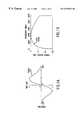
- FIGS. 1A and 1Bshow a 2 GHz center frequency monocycle pulse in the time and frequency domains, respectively, in accordance with the present invention.
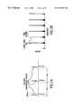
- FIGS. 2A and 2Bare illustrations of a 1 mpps system with 1 ns pulses in the time and frequency domains, respectively, in accordance with the present invention.
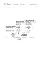
- FIG. 3illustrates a modulating signal that changes the pulse repetition interval (PRI) in proportion to the modulation in accordance with the present invention.
- FIG. 4is a plot illustrating the impact of pseudo-random dither on energy distribution in the frequency domain in accordance with the present invention.
- FIG. 5illustrates the result of a narrowband sinusoidal (interference) signal overlaying an impulse radio signal in accordance with the present invention.
- FIG. 6shows the “cross correlator” transfer function of an impulse radio receiver in accordance with the present invention.
- FIG. 7illustrates impulse radio multipath effects in accordance with the present invention.
- FIG. 8illustrates the phase of the multipath pulse in accordance with the present invention.
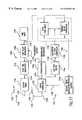
- FIG. 9shows a representative block diagram of a full duplex impulse radio system, in accordance with the present invention.
- FIG. 10shows timing of transmitted and received pulses at a transceiver.
- FIG. 11shows contention zones between an impulse radio transmitter and receiver.
- FIG. 12shows a delay transmit technique to minimize the affect of contention zones between an impulse radio transmitter and receiver, in accordance with an embodiment of the present invention.
- FIG. 13shows a flow diagram for a pulse interleaving technique for full duplex impulse radio communications, in accordance with an embodiment of the present invention.
- FIG. 14shows a flow diagram for a burst interleaving technique for full duplex impulse radio communications, in accordance with an embodiment of the present invention.
- FIG. 15shows exemplary pulses for a further embodiment of the present invention using different pulse repetition frequencies for two communicating transceivers.
- FIG. 16illustrates the cross correlation process in accordance with the present invention.
- FIG. 17shows a representative illustration of an impulse radio transceiver for full duplex communications, in accordance with an embodiment of the present invention.
- FIG. 18shows a representative illustration of an impulse radio transceiver for full duplex communications, in accordance with another embodiment of the present invention.
- FIG. 19shows an exemplary block diagram of a transceiver implemented for synchronizing pulse interleaving, according to a preferred embodiment of the present invention.
- FIG. 20shows a flow diagram to implement a delay for pulse interleaved communications.
- Impulse radio technologyis widely applicable for wireless communications applications. Because impulse radio is not a continuous wave (CW) carrier-based system, the use of a subcarrier is an elegant, counter intuitive addition to the time domain impulse radio design. Signal-to-noise ratio is thereby improved considerably compared to non-subcarrier impulse radio transmissions.
- CWcontinuous wave
- Impulse radiosgenerally have: short duration pulses; center frequencies typically between 50 MHz and 10 gigahertz (GHz); ultrawide bandwidths of 100+% of the center frequency; multi-mile ranges with sub-milliwatt average power levels, even with low gain antennas; extremely low power spectral densities; lower cost than other sophisticated radio designs, especially spread spectrum systems; and excellent immunity to jamming from other systems and to multipath fading.
- center frequenciestypically between 50 MHz and 10 gigahertz (GHz); ultrawide bandwidths of 100+% of the center frequency
- multi-mile ranges with sub-milliwatt average power levels, even with low gain antennasextremely low power spectral densities
- lower cost than other sophisticated radio designs, especially spread spectrum systemsand excellent immunity to jamming from other systems and to multipath fading.
- Impulse radioshave exceptional multipath immunity and are relatively simple and less costly to build, especially in comparison to spread spectrum radios.
- Impulse radio systemsconsume substantially less power than existing conventional radios. Additionally, impulse radio systems occupy less space than existing portable telecommunications transceivers. Because of these characteristics, impulse radio is an optimal technology for a wide variety of applications, including personal communications systems and in-building communications systems.
- Section IIis directed to technology basics and provides the reader with an introduction to impulse radio concepts, as well as other relevant aspects of communications theory.
- Section IIIis directed full duplex for impulse radio communication systems. This section includes subsections relating to the theory of operation of full duplex for an impulse radio transceiver.
- this sectionis directed to technology basics and provides the reader with an introduction to impulse radio concepts, as well as other relevant aspects of communications theory.
- This sectionincludes subsections relating to Gaussian monocycle pulses, pulse trains of gaussian monocycle pulses, modulation, coding, and qualitative and quantitative characteristics of these concepts.
- Impulse radio transmittersemit short Gaussian monocycle pulses with a tightly controlled average pulse-to-pulse interval.
- Impulse radio transmittersuse pulse widths of between 20 and 0.1 nanoseconds (ns) and pulse-to-pulse intervals of between 2 and 5000 ns. These narrow monocycle pulses have inherently wide-band frequency characteristics.
- Impulse radio systemsuses pulse position modulation, with the actual pulse-to-pulse interval being varied on a pulse-by-pulse basis by two components: an information component and a pseudo-random code component.
- the pseudo-random codeis not necessary for energy spreading (because the impulses themselves are inherently wide-band), but rather for channelization, energy smoothing in the frequency domain, and jamming resistance.
- the impulse radio receiveris a direct conversion receiver with a cross correlator front end.
- the front endcoherently converts the electromagnetic pulse train to a baseband signal in one stage.
- the impulse radio receiverintegrates multiple pulses to recover each bit of the transmitted information.
- Gaussian monocycleswhich are also referred to herein as Gaussian monocycle pulses.
- a Gaussian monocycleis the first derivative of the Gaussian function.
- FIGS. 1A and 1Bshow a 2 GHz center frequency (i.e., a 0.5 ns pulse width) monocycle pulse in the time and frequency domains (see 102 and 104 , respectively).
- a 2 GHz center frequencyi.e., a 0.5 ns pulse width
- monocycleswhich are sometimes called impulses, are not gated sine waves.
- the Gaussian monocycle waveformis naturally a wide bandwidth signal, with the center frequency and the bandwidth completely dependent upon the pulse's width.
- Ais the peak amplitude of the pulse
- ⁇ (tau)is a time decay constant.
- V ⁇ ( ⁇ )A ⁇ ⁇ ⁇ ⁇ ⁇ ⁇ 2 ⁇ 2 ⁇ ⁇ ⁇ ⁇ ⁇ e ⁇ ⁇ - ⁇ ⁇ 2 ⁇ ⁇ 2 2 ( 2 )
- the bandwidthis approximately 160% of the center frequency. Because ⁇ (tau) also defines the pulse width, then the pulse width specifies both the center frequency and bandwidth. In practice, the center frequency of a monocycle pulse is approximately the reciprocal of its length, and its bandwidth is approximately equal to 1.6 times the center frequency. Thus, for the “0.5 ns” pulse shown in FIGS. 1 A and 1 B:
- Impulse radio systemsuse pulse trains, not single pulses, for communications. As described in detail in Section III below, the impulse radio transmitter produces and outputs a train of pulses for each bit of information.
- FIGS. 2A and 2Bare illustrations of a 1 mpps system with (uncoded, unmodulated) 1 ns pulses in the time and frequency domains (see 102 and 104 , respectively).
- this highly regular pulse trainproduces energy spikes (comb lines 204 ) at one megahertz intervals; thus, the already low power is spread among the comb lines 204 .
- This pulse traincarries no information and, because of the regularity of the energy spikes, might interfere with conventional radio systems at short ranges.
- impulse radio systemshave very low duty cycles so the average power in the time domain is significantly lower than the peak power in the time domain.
- the impulse transmitteroperates 0.1% of the time (i.e., 1 ns per microsecond ( ⁇ s)).
- Amplitude and frequency/phase modulationare unsuitable for this particular form of impulse communications; the only suitable choice is pulse position modulation, which allows the use of a matched filter (i.e., cross correlator) in the receiver. As illustrated in FIG. 3, a modulating signal changes the pulse repetition interval (PRI) in proportion to the modulation.
- PRIpulse repetition interval
- the first levelmight shift the generation of the pulse forward in time from the nominal by ⁇ picoseconds (ps); the second level might not shift the pulse position in time from the nominal at all; and the third level might delay the pulse by ⁇ ps.
- Analog modulationwould allow continuous deviations between PRI- ⁇ and PRI+ ⁇ .
- pulse position modulationdistributes the energy over more frequencies.
- the modulation dither (d)is 100 ps
- the PRIis 1,000,000 Hertz (Hz) and the additional frequency components are: 999,800.04 Hz, 999,900.01 Hz, 1,000,100.01 Hz, and 1,000,200.04 Hz.
- Ditheris an impulse radio communications term for moving the position of a pulse in time.
- Transmitted energyis now distributed among more spikes (comb lines) in the frequency domain. If the total transmitted energy remains constant, the energy in each frequency spike decreases as the number of possible pulse positions increases. Thus, in the frequency domain, the energy is more smoothly distributed.
- PN ditheringalso provides for channelization (channelization is a procedure employed to divide a communications path into a number of channels). In an uncoded system, differentiating between separate transmitters would be very hard. PN codes create channels, if the codes themselves are relatively orthogonal (i.e., there is low correlation and/or interference between the codes being used).
- an impulse radiodoes not depend on receiving every pulse.
- the impulse radio receiverperforms a correlating, synchronous receiving function (at the RF level) that uses a statistical sampling of many pulses to recover the transmitted information.
- the PN codingalso makes impulse radio highly resistant to jamming from all radio communications systems, including other impulse radio transmitters. This is critical as any other signals within the band occupied by an impulse signal act as a jammer to the impulse radio. Since there are no unallocated 1+ GHz bands available for impulse systems, they must share spectrum with other conventional and impulse radios without being adversely affected.
- the PN codehelps impulse systems discriminate between the intended impulse transmission and transmissions from others.
- the pseudo-randomization in time of the receive processcreates a stream of randomly distributed values with a mean of zero (for jamming signals). Therefore, to eliminate the impact of jammers all that is necessary is to sample over enough pulses (i.e., integrate over a sufficiently large number of pulses) to drive the impact of the jamming signals to zero.
- Impulse radiois jam resistant because of its large processing gain.
- processing gainwhich quantifies the decrease in channel interference when wide-band communications are used, is the ratio of the bandwidth of the channel to the bandwidth of the information signal.
- a direct sequence spread spectrum system with a 10 kHz information bandwidth and a 16 MHz channel bandwidthyields a processing gain of 1600 or 32 dB.
- far greater processing gainsare achieved with impulse radio systems where, for the same 10 kHz information bandwidth and a 2 GHz channel bandwidth, the processing gain is 200,000 or 53 dB.
- the duty cycle(e.g., of 0.5%) yields a process gain of 28.3 dB.
- the process gainis generally the ratio of the bandwidth of a received signal to the bandwidth of the received information signal.
- the effective oversampling from integrating over multiple pulses to recover the information(e.g., integrating over 200 pulses) yields a process gain of 28.3 dB.
- a 2 GHz divided by a 10 mpps link transmitting 50 kilobits per second (kbps)would have a process gain of 49 dB, (i.e., 0.5 ns pulse width divided by a 100 ns pulse repetition interval would have a 0.5% duty cycle, and 10 mpps divided by a 50,000 bps would have 200 pulses per bit.)
- FIG. 6shows the “cross correlator transfer function” 602 . This represents the output value of an impulse radio receiver cross correlator for any given received pulse. As illustrated at 604 , the cross correlator's output is 0 volts when pulses arrive outside of a cross correlation window 606 . As a received pulse 608 slides through the window, the cross correlator output varies.
- the cross correlator's outputhas a swing of between ⁇ 1 volt (as a function of the transmitter's modulation).
- Other in-band transmissionwould cause a variance to the cross correlator's output value.
- This varianceis a random variable and can be modelled as a Gaussian white noise signal with a mean value of 0. As the number of interferers increases, the variance increases linearly. By integrating over a large number of pulses, the receiver develops an estimate of the transmitted signal's modulation value.
- ⁇is the variance of all the interferers to a single cross correlation
- Zis the number of pulses over which the receiver integrates to recover the modulation.
- Multipath fadingthe bane of sinusoidal systems, is much less of a problem (i.e., orders of magnitude less) for impulse systems than for conventional radio systems.
- Rayleigh fadingso noticeable in cellular communications, is a continuous wave phenomenon, not an impulse communications phenomenon.
- Pulses traveling between these intervalsdo not cause self-interference (in FIG. 7, this is illustrated by the pulse traveling Path 2 ). However, pulses traveling grazing paths, as illustrated in FIG. 7 by the narrowest ellipsoid, create impulse radio multipath effects.
- the multipath pulsetravels one half width of a pulse width further, it increases the power level of the received signal (the phase of the multipath pulse will be inverted by the reflecting surface). If the pulse travels less than one half a pulse width further, it will create destructive interference as shown at 804 . For a 1 ns pulse, for example, destructive interference will occur if the multipath pulse travels between 0 and 15 cm (0 and 6 inches).
- a representative block diagram of a full duplex impulse radio communication systemis shown in FIG. 9.
- a first transceiver (A) 902comprises a transmitter (T 1 ) 904 and a receiver (R 1 ) 906 .
- a second transceiver (B) 908comprises a transmitter (T 2 ) 910 and a receiver (R 2 ) 912 .
- the transceivers 902 and 908are separated by a propagation medium 914 , such as air, space, or other medium cable of propagating ultrawide-band signals.
- Transmitted impulse radio signals 916propagate through the propagation medium 914 between T 1 904 and R 2 912 , and between T 2 910 and R 1 906 .
- the purpose for full duplex transmission in an ultrawide band impulse radio systemis to provide two-way transmittal of information similar to telephony, as opposed to a walkie-talkie (i.e., a push-to-talk simplex operation). Since ultrawide band signals utilize the full electromagnetic spectrum, or at least a very large part of it, it is necessary to use some technique other than frequency domain duplexing, which is the conventional method. The inventors have therefore developed a pulse interleaving technique for full dupiex impulse radio communications.
- transmitter T 1 904sends out a train of modulated pulses 1002
- receiver R 1 906would need to receive pulses 1004 transmitted from transmitter T 2 910 during the time periods between the pulses 1002 transmitted by T 1 .
- T 1 904is set to emit each pulse 1202 10 nanoseconds (ns) after R 1 906 receives a pulse 1204 from T 2 910 .
- This transmit delayis depicted in FIG. 12 . This reduces interference between the transmitter and the receiver at transceiver 1 , for example. If T 1 904 transmits after it receives a pulse, those pulses cannot interfere. Since T 1 904 has waited for over a whole period (one period is about 5 ns) before transmitting, most of the noise from the previous pulse has died down before the current pulse is transmitted. However, some contention zones 1206 will still exist between the two transmitters.
- the easiest way to resolve these contention zones 1206is to permit the first transceiver to have a choice of say, 10 ns or 100 ns of delay before transmitting after receiving a pulse. This removes the interference at point 1208 for example, by pushing (position in time) pulse 1210 up to point 1212 so that the self-interference is avoided.
- each pulseis also time dither coded as described above. They are shown here as un-time dither coded for simplicity. Thus, time dither coding further serves to remove the interface 1208 .
- T 1 904would begin transmitting to R 2 912 , as shown at a step 1302 .
- R 2 912scans for detection and acquires lock through its scanning mechanism (see step 1304 ). Once it acquires lock (see step 1306 ), its accompanying transmitter (T 2 910 ) can begin transmitting, as shown at a step 1308 .
- R 1 906then scans for detection, at step 1310 . If R 1 906 happens to be in a contention zone, then it will never acquire lock to T 2 910 .
- R 1 906must wait for an acknowledge message (ACK) 1306 to be conveyed to it by T 1 904 before it knows whether to use the 10 ns or the 100 ns transmitter receive timing delay. If it never receives, or after a certain time does not receive the ACK that R 1 906 has acquired T 2 910 , then T 2 910 times-out and shifts its transmitted pulse timing by 100 ns, for example, and tries again. These steps are shown generally by a conditional loop at steps 1312 , 1314 , 1316 and 1318 .
- R 2 912does acquire lock (i.e., receives an ACK from T 1 904 sent at step 1320 ) as shown at step 1322 , T 2 910 will transmit a return ACK at step 1324 , a link is established, and the transceivers are in lock.
- the timeoutis preferably the maximum time period required for R 2 912 to scan for a pulse from T 1 904 over the entire modulo of the dither code. For a 256 bit code, and a fairly small code dither of 10 ns a timeout can take up to 20 seconds. Timeout is only done for an initial lock. A timeout is not needed if the transceivers switch codes or delay values. Because of the simplicity in implementation of the pulse interleave technique, pulse interleave full duplex is very economical for many communication applications, such as telemetry and transponder-type systems. In the preferred embodiment, the receiver can stay on so that a cold start is not necessary.
- the mobile environmentpresents unique contention zone problems. Therefore, the following embodiments deal with the mobile environment explicitly, and are specifically directed at providing immunity to dead or contention zone problems.
- T 1 904starts the process by transmitting a burst (see step 1402 ), which, for example, could be 10 microseconds in length.
- each burstcontains 20 pulses at a 2 megapulse per second rate, or 50 pulses at a 5 megapulse rate.
- This first transmitted burstis received by R 2 912 after a certain amount of time passes due to propagation delay (i.e., range delay) and scanning delay by R 2 912 (see step 1404 ).
- Range delaycorresponds to about 5.2 microseconds per mile (approximately 5,200 feet) or about one foot per nanosecond.
- R 2acquires lock (see step 1406 ) and then T 2 910 transmits its burst containing information modulation (at step 1408 ), and after the same range delay, R 1 scans for detection (step 1410 ) and acquires lock (step 1412 ). If the timing between the bursts is sufficient, then under no circumstance(s) of position or range between the transceivers do the bursts collide. The criterion is that the delay between bursts be sufficient to accommodate the round trip delay and burst width. In practice, the burst should be as far away as possible before using up all the margin of receive time in this receiver before it will be required to transmit again. The transceivers then swap acquisition messages, as shown at steps 1414 , 1416 , 1418 and 1420 , to complete the locking process.
- a further embodiment of the present inventionuses code division multiple access (CDMA) for achieving full duplex communication in an ultrawide band impulse radio system.
- CDMAcode division multiple access
- T 1 904 and T 2 910are operated with different time dither codes, with dither windows nearly equalling the full frame so that each successive pulse can appear anywhere within the period separating the pulses.
- the dither windowis the period within which a monocycle can occur when position modulated by a dither code.
- T 1 904 and T 2 910can even use the same dither code because a time delay between them permits decorrelation. Typically, however, they would be operated on different time dither codes.
- T 1 904generates a blanking pulse that prevents receiving any energy within a certain amount of time after transmission, for example, 10 ns. This allows the antennas in the local environment to ring down or dampen energy for opening the receiver for possible received pulse. For example, a pulse width of 0.5 ns (or center frequency of 2 gigahertz), with a period of 200 ns (which is the repetition rate of 5 megapulses per second), produces a cycle of 1 in 400 (i.e., 0.25%).
- a blanking pulse equalling the transmitted pulse emittedis, however, not entirely effective. There is still sufficient energy ringing down in the environment and in the antenna that may cause significant self-interference. Statistically, pulses can align themselves perfectly in only about 1 in 400 pulses. The blanking window of 10 ns increases the probability of a received pulse being within that blanking window, up to 1%. A 1% probability means that 1% of the energy is thrown away by the receiver. A loss of only 1% of transmitted energy is a very small penalty to exact to allow for a full duplex operation. This 1% reduction likely unmeasurable.
- Blankingcan be implemented in many ways. Descrete logic can be used to determine when received pulses and transmitted pulses of two different pulse repitition rates will interfere or occur too close in time. Interference is avoided by gating off one of the trigger signals (for example).
- This FDMA embodimenthas some of the advantages of the pulse interleaving embodiment, such as 100% availability of the transmitter.
- the pulse interleaving embodimentrequires the transmitter to be turned off for a significant fraction at the transmitting cycle.
- the disadvantagebeing, for the same average of transmitted power, the pulse power has to be that much higher to make up for it.
- the duty cycle in the first examplewas on the order of 33%. Therefore the pulse power (i.e., the instantaneous pulse power), would have to be 66% larger.
- This last embodimentshares the advantages of pulse interleave—100% availability of the carrier—but it is never turned off on transmit. On receiving however, the periodic self-interference is taken care of by blanking, as in the previous example, reducing the received power availability by only 1%, a perfectly acceptable number.
- the method used to provide for isolation between a transmitter and a receiver for a full duplex impulse radio linkis different than for conventional radios because conventional radios operate using continuous wave carrier frequencies. These carrier frequencies can be very narrow-band and as such, frequency domain techniques can be used to isolate the transmitter from the receiver in the same view. Low pass filters can be used on the transmitter to prevent spurious energy from getting into a receiver, which is operated at a slightly higher frequency. Conversely, a high pass filter is used to eliminate power from the transmitter from getting into the receiver. This conventional filtering, however, cannot effectively be applied to impulse radio systems because the transmitter and receiver use the same pulse with monocycle.
- FIG. 16Two monocycles pulses with different center frequencies are shown in FIG. 16.
- a long monocycle 1602has a low frequency content, and a shorter monocycle 1604 has a higher center frequency. Although these two pulses differ in center frequency by nearly 3 to 1, they still significantly overlap. Therefore, even in this case a filter can be used to provide some isolation between a transmitter and a receiver, operating at one center frequency (f C1 ) on the uplink and different center frequency (f C2 ) on the downlink. In this embodiment contention is completely eliminated by the fact that different center frequencies are used in operation.
- the dither windowis the period within which a monocycle can occur as positioned by a dither code.
- the dither windowis 5 ns wide.
- Each dither windowis separated by 200 ns.
- a subsequent monocyclecan occur anywhere within the next dither window, and at a minimum, 200 ns later.
- the concentration of pulses in a relatively narrow time zone in each frame, where a frame is the nominal interpulse intervalcontributes to increased interference with conventional services, as well as increased interference with like transceivers.
- the increased interferenceis an undesirable consequence of the difficulty of making wider dither windows.
- the difficultylies in the fact that long time delays are difficult to make with low jitter. Because this is a coherent communication scheme, low jitter is important for efficient conversion of a pulse and for good signal-to-noise ratio at low RF power levels.
- a preferred embodiment of an impulse radio transmitter 904 or 910 of an impulse radio communication systemwill now be described with reference to FIG. 17 .
- An impulse radio receiver 1701will now described with reference to FIG. 17 .
- An impulse radio receiver (hereafter called the receiver) 1701comprises a receive antenna 1726 for receiving a propagated impulse radio signal 1724 .
- a received signalis input to a cross correlator 1728 via a receiver transmission line 1730 , coupled to the receive antenna 1726 .
- the baseband signal 1740is also input to a lowpass filter 1746 .
- the lowpass filter 1746generates an error signal 1748 for an acquisition and lock controller 1750 to provide minor phase adjustments to the adjustable time base 1734 .
- a detailed description of an impulse radio receiveris included in the '973 application.
- FIG. 18is a transceiver block diagram for the burst interleave embodiment of the present invention.
- a transmitter burst controller 1802 and a receiver burst controller 1804are added to the basic architecture of the transceiver of FIG. 17 .
- These two controllersare state machines that can be hardwired or programmably controlled (using EEPROMS, or the like) to time position the modulated, coded timing signal 1714 and to time modulate the periodic timing signal 1738 , respectively, in accordance with the burst interleave operation described above.
- the delay required for the pulse interleave embodiment of the present inventionis determined and provided by the acquisition and lock controller 1750 .
- the pulse repetition rate, dither window andare hardwired or programmably controlled into the burst controllers 1802 , 1804 and the acquisition and lock controller 1750 , for example.
- Other control features and modifications to the disclosed transceiver components/controllerswould be apparent to a person skilled in the relevant art without departing from the scope of the present invention.
- each receivermust measure the time between the reception of a pulse from another transceiver and the trigger to its own transmitter (this which can be accomplished with conventional circuitry).
- a minimum limite.g. 20 ns
- itnotifies the other transceiver to synchronously change its receive timing (and the first transceiver will change its transmit timing) at, for example, the first pulse of the second code modulo from now.
- “now”is a point in time determined by the first transceiver as a reference point in time that is communicated to the second transceiver (or otherwise inferred by the second transceiver) for synchronization.
- modulosare long enough to encode at least one whole bit, and that therefore can serve as a trigger for the counting of whole modulos. Since the coder keeps track of the pulse “count” in order to apply the correct time dither to the decoder, this method can indirectly identify individual pulses for the purpose of synchronization.
- the DSP 1902also outputs massaging information 1916 to be modulated with the data to accomplish the synchronization with the other transceiver.
- a analog-to-digital (A/D) converteris shown at 1918 , because the DSP need to process the cross correlator output in the digital domain.
- FIG. 20shows a flow diagram of the DSP operation to implement a delay for pulse interleaved communications.
- the transceiversacquire lock 2004 , as described above. If a time (t) between a transmitted pulse and a received pulse is less than 20 ns, as shown at a decisional block 2006 , a 100 ns delay is negotiated between the two transceivers at 2008 . This is termed a negotiation, since either transceiver can perform the necessary delay. The negotiation is carried out via massaging 1916 . If lock is lost, as determined by decisional block 2010 , acquisition must be repeated, as shown at 2012 .
- the transmitter and receiver comprising a transceiverare operated at two different rates, then it is not possible to “interleave” the pulses, since they “beat” with each other (i.e., the timing of the pulse trains will periodically cause the transmitted and received pulses to periodically coincide).
- a mechanism similar to the detector described abovecan be used to detect the minimum pulse separation condition. However, this signal will be employed in a different way: either to blank the trigger to the correlator or to the transmitter. Either response will have the desired result of preventing self interference, but they have different tradeoffs in a communications system.
- the transmitterIf the transmitter is blanked, it will reduce the transmitted power and interfere with the carrier which would be received by another transceiver, due to the gaps in the carrier which result from the blanking action. However, it increases the received power to the first transceiver, since it will not have to throw away the pulses which occur within this minimum separation window as would be the case if the receiver is blanked instead.
- the communications methods described herehave been observed to be usable not only using radio (electromagnetic) impulsive waveforms, but also may use acoustic signals.
- the principle differences in the latter approachare: (1) frequency of operation and (2) signal transmission.
- the frequency of operationis primarily between a few tens of Hertz (e.g., pulses of a duration of several tens of milliseconds), up to a few hundred Megahertz (e.g., pulses with durations of a few nanoseconds).
- Acoustic transducersare employed in the acoustic approach rather than the antennas, which are used for the radio approach.
- the signal characteristics of the transducersare similar to the signal characteristics required by the antennas used in the radio approach in that they must be capable of transmitting and/or receiving waveforms with bandwidths of ⁇ 100% of the center frequency (without more than a few percent dispersion, and with good conversion gain).
- Transducersmay be made from a material called Kynar Film supplied by Pennwalt Corporation in Valley Forge, Pa. The geometry of a transducer made from this type as would become apparent to a person skilled in the relevant art.
Landscapes
- Engineering & Computer Science (AREA)
- Signal Processing (AREA)
- Computer Networks & Wireless Communication (AREA)
- Mobile Radio Communication Systems (AREA)
Abstract
Description


Claims (10)
Priority Applications (2)
| Application Number | Priority Date | Filing Date | Title |
|---|---|---|---|
| US09/458,010US6549567B1 (en) | 1994-09-20 | 1999-12-10 | Full duplex ultrawide-band communication system and method |
| US10/411,090US7321611B2 (en) | 1994-09-20 | 2003-04-11 | Method and transceiver for full duplex communication of ultra wideband signals |
Applications Claiming Priority (6)
| Application Number | Priority Date | Filing Date | Title |
|---|---|---|---|
| US08/309,973US5677927A (en) | 1994-09-20 | 1994-09-20 | Ultrawide-band communication system and method |
| US08/428,489US5687169A (en) | 1995-04-27 | 1995-04-27 | Full duplex ultrawide-band communication system and method |
| US48799095A | 1995-06-07 | 1995-06-07 | |
| US08/761,602US5832035A (en) | 1994-09-20 | 1996-12-06 | Fast locking mechanism for channelized ultrawide-band communications |
| US15857098A | 1998-09-22 | 1998-09-22 | |
| US09/458,010US6549567B1 (en) | 1994-09-20 | 1999-12-10 | Full duplex ultrawide-band communication system and method |
Related Parent Applications (1)
| Application Number | Title | Priority Date | Filing Date |
|---|---|---|---|
| US15857098AContinuation | 1994-09-20 | 1998-09-22 |
Related Child Applications (1)
| Application Number | Title | Priority Date | Filing Date |
|---|---|---|---|
| US10/411,090ContinuationUS7321611B2 (en) | 1994-09-20 | 2003-04-11 | Method and transceiver for full duplex communication of ultra wideband signals |
Publications (1)
| Publication Number | Publication Date |
|---|---|
| US6549567B1true US6549567B1 (en) | 2003-04-15 |
Family
ID=27405424
Family Applications (2)
| Application Number | Title | Priority Date | Filing Date |
|---|---|---|---|
| US08/761,602Expired - LifetimeUS5832035A (en) | 1994-09-20 | 1996-12-06 | Fast locking mechanism for channelized ultrawide-band communications |
| US09/458,010Expired - Fee RelatedUS6549567B1 (en) | 1994-09-20 | 1999-12-10 | Full duplex ultrawide-band communication system and method |
Family Applications Before (1)
| Application Number | Title | Priority Date | Filing Date |
|---|---|---|---|
| US08/761,602Expired - LifetimeUS5832035A (en) | 1994-09-20 | 1996-12-06 | Fast locking mechanism for channelized ultrawide-band communications |
Country Status (1)
| Country | Link |
|---|---|
| US (2) | US5832035A (en) |
Cited By (129)
| Publication number | Priority date | Publication date | Assignee | Title |
|---|---|---|---|---|
| US20020018458A1 (en)* | 1999-09-10 | 2002-02-14 | Fantasma Network, Inc. | Baseband wireless network for isochronous communication |
| US20030128772A1 (en)* | 2001-07-23 | 2003-07-10 | Lachlan Michael | Wireless impulse transmitter, receiver, and method |
| US20030193924A1 (en)* | 1999-09-10 | 2003-10-16 | Stephan Gehring | Medium access control protocol for centralized wireless network communication management |
| US20030235235A1 (en)* | 2002-06-21 | 2003-12-25 | Pulse-Link, Inc. | Ultra-wideband communication through a wired network |
| US20040022304A1 (en)* | 2002-06-21 | 2004-02-05 | John Santhoff | Ultra-wideband communication though local power lines |
| US20040047285A1 (en)* | 2002-09-11 | 2004-03-11 | Foerster Jeffrey R. | Sub-banded ultra-wideband communications system |
| US20040090983A1 (en)* | 1999-09-10 | 2004-05-13 | Gehring Stephan W. | Apparatus and method for managing variable-sized data slots within a time division multiple access frame |
| US20040141561A1 (en)* | 2002-06-21 | 2004-07-22 | John Santhoff | Ultra-wideband communication through twisted-pair wire media |
| US20040156446A1 (en)* | 2002-06-21 | 2004-08-12 | John Santhoff | Optimization of ultra-wideband communication through a wire medium |
| WO2003105386A3 (en)* | 2002-06-05 | 2004-09-30 | Nokia Corp | Digital video broadcast-terrestrial (dvb-t) receiver interoperable with a gsm transmitter in a non-interfering manner |
| US6801153B2 (en)* | 2001-11-02 | 2004-10-05 | Spectrum Target Detection, Inc. | Spread spectrum radar with leak compensation at baseband |
| WO2004098074A3 (en)* | 2003-04-29 | 2004-12-29 | Pulse Link Inc | Ultra-wideband pulse modulation system and method |
| US20050008371A1 (en)* | 1999-11-16 | 2005-01-13 | Lundholm Andrew S. | Method and apparatus for communicating in the presence of radio frequency energy |
| US20050018762A1 (en)* | 1999-11-03 | 2005-01-27 | Roberto Aiello | Ultra wide band communication systems and methods |
| US20050023409A1 (en)* | 2003-07-28 | 2005-02-03 | Moshe Shnaps | System and method for munition impact assessment |
| US6853674B1 (en)* | 1999-12-20 | 2005-02-08 | Pasi Into Loukas | Variable wavelength impulse transmission |
| US20050053165A1 (en)* | 2001-12-06 | 2005-03-10 | Ismail Lakkis | Ultra-wideband communication apparatus and methods |
| US20050053121A1 (en)* | 2001-12-06 | 2005-03-10 | Ismail Lakkis | Ultra-wideband communication apparatus and methods |
| US20050058107A1 (en)* | 2003-09-12 | 2005-03-17 | Juha Salokannel | Method and system for repeat request in hybrid ultra wideband-bluetooth radio |
| US20050058180A1 (en)* | 2001-12-06 | 2005-03-17 | Ismail Lakkis | Ultra-wideband communication apparatus and methods |
| US20050059345A1 (en)* | 2003-09-12 | 2005-03-17 | Arto Palin | Method and system for establishing a wireless communications link |
| US20050058116A1 (en)* | 2003-09-12 | 2005-03-17 | Arto Palin | Method and system for processing acknowledgments in a wireless communications network |
| US20050058152A1 (en)* | 2003-09-12 | 2005-03-17 | Oksanen Markku A. | Ultra-wideband/low power communication having a dedicated memory stick for fast data downloads - apparatus, systems and methods |
| US20050068932A1 (en)* | 2000-09-25 | 2005-03-31 | Ismail Lakkis | Ultra-wideband communication system and methods |
| US20050069020A1 (en)* | 2001-12-06 | 2005-03-31 | Ismail Lakkis | Ultra-wideband communication apparatus and methods |
| US20050074054A1 (en)* | 2003-09-24 | 2005-04-07 | Spectrum5, Inc. | Matched filter for scalable spread spectrum communications systems |
| US20050097408A1 (en)* | 2003-10-29 | 2005-05-05 | Nokia Corporation | Method and system for providing communications security |
| US20050152483A1 (en)* | 2001-12-06 | 2005-07-14 | Ismail Lakkis | Systems and methods for implementing path diversity in a wireless communication network |
| US20050190739A1 (en)* | 2000-06-21 | 2005-09-01 | Carlton Sparrell | Wireless TDMA system and method for network communications |
| US6952456B1 (en) | 2000-06-21 | 2005-10-04 | Pulse-Link, Inc. | Ultra wide band transmitter |
| US20050233710A1 (en)* | 2001-12-06 | 2005-10-20 | Ismail Lakkis | High data rate transmitter and receiver |
| US20050282494A1 (en)* | 2004-06-18 | 2005-12-22 | Jouni Kossi | Techniques for ad-hoc mesh networking |
| US20060056352A1 (en)* | 2002-11-15 | 2006-03-16 | Widefi, Inc. | Wireless local area network repeater with detection |
| US20060063484A1 (en)* | 2002-10-24 | 2006-03-23 | Proctor James A Jr | Wireless local area network repeater with in-band control channel |
| US20060063485A1 (en)* | 2002-10-15 | 2006-03-23 | Gainey Kenneth M | Wireless local area network repeater with automatic gain control for extending network coverage |
| US20060098592A1 (en)* | 2002-12-16 | 2006-05-11 | Widefi, Inc. | Wireless network repeater |
| US20060135195A1 (en)* | 2004-12-22 | 2006-06-22 | Nokia Corporation | Interoperability improvement between receivers and transmitters in a mobile station |
| US20060165127A1 (en)* | 2005-01-24 | 2006-07-27 | Nunally Patrick O | System and method for broadband network communication through operational natural gas infrastructures |
| US7099368B2 (en) | 2002-06-21 | 2006-08-29 | Pulse-Link, Inc. | Ultra-wideband communication through a wire medium |
| US20060193271A1 (en)* | 2005-01-28 | 2006-08-31 | Widefi, Inc. | Physical layer repeater configuration for increasing MIMO performance |
| US20060274817A1 (en)* | 2000-09-25 | 2006-12-07 | Lakkis Ismail A | Method and apparatus for wireless communications |
| US20070018792A1 (en)* | 2004-03-17 | 2007-01-25 | Brother Kogyo Kabushiki Kaisha | Position detecting system, responder and interrogator, wireless communication system, position detecting method, position detecting program, and information recording medium |
| US20070025486A1 (en)* | 2002-10-01 | 2007-02-01 | Widefi, Inc. | Control message management in physical layer repeater |
| US20070032192A1 (en)* | 2004-06-03 | 2007-02-08 | Widefi, Inc. | Frequency translating repeater with low cost high performance local oscillator architecture |
| US20070047625A1 (en)* | 2005-08-31 | 2007-03-01 | Klomsdorf Armin W | Multi-mode wireless communication device and method |
| US20070082622A1 (en)* | 2004-12-22 | 2007-04-12 | Nokia Corporation | Interoperability improvement between receivers and transmitters in a mobile station |
| US20070117514A1 (en)* | 2005-11-22 | 2007-05-24 | Widefi, Inc. | Directional antenna configuration for TDD repeater |
| US20070143078A1 (en)* | 2001-03-26 | 2007-06-21 | Martin Vetterli | Sampling method, reconstruction method, and device for sampling and/or reconstructing signals |
| US20070162964A1 (en)* | 2006-01-12 | 2007-07-12 | Wang Liang-Yun | Embedded system insuring security and integrity, and method of increasing security thereof |
| US20070242026A1 (en)* | 2006-04-14 | 2007-10-18 | Qualcomm Incorporated | Apparatus and method of pulse generation for ultra-wideband transmission |
| US20070248114A1 (en)* | 2006-04-20 | 2007-10-25 | Qualcomm Incorporated | Media access control for ultra-wide band communication |
| US20070249288A1 (en)* | 2006-04-14 | 2007-10-25 | Kamran Moallemi | Distance-based security |
| US20070254728A1 (en)* | 2006-04-26 | 2007-11-01 | Qualcomm Incorporated | Dynamic distribution of device functionality and resource management |
| US20070259629A1 (en)* | 2006-04-26 | 2007-11-08 | Qualcomm Incorporated | Duty cycling power scheme |
| US20070257827A1 (en)* | 2006-04-20 | 2007-11-08 | Qualcomm Incorporated | Low power output stage |
| US20070259690A1 (en)* | 2006-04-14 | 2007-11-08 | Qualcomm Incorporated | Distance-based presence management |
| US20070281721A1 (en)* | 2006-04-26 | 2007-12-06 | Qualcomm Incorporated | Methods and apparatuses of initiating communication in wireless networks |
| US20070279237A1 (en)* | 2006-04-26 | 2007-12-06 | Qualcomm Incorporated | Wireless localization apparatus and method |
| US20070286274A1 (en)* | 2006-04-19 | 2007-12-13 | Qualcomm Incorporated | Apparatus and method of low latency multi-hop communication |
| US20070285306A1 (en)* | 2006-04-18 | 2007-12-13 | Qualcomm Incorporated | Verified distance ranging |
| US20080043824A1 (en)* | 2006-04-18 | 2008-02-21 | Qualcomm Incorporated | Offloaded processing for wireless applications |
| US20080043654A1 (en)* | 2001-12-06 | 2008-02-21 | Lakkis Ismail A | Systems and methods for wireless communication over a wide bandwidth channel using a plurality of sub-channels |
| US20080056332A1 (en)* | 2001-12-06 | 2008-03-06 | Ismail Lakkis | Ultra-wideband communication systems and methods |
| US20080056333A1 (en)* | 2001-12-06 | 2008-03-06 | Ismail Lakkis | Ultra-wideband communication apparatus and methods |
| US20080056186A1 (en)* | 2001-12-06 | 2008-03-06 | Ismail Lakkis | Ultra-wideband communication systems and methods |
| US20080107199A1 (en)* | 2001-12-06 | 2008-05-08 | Ismail Lakkis | Systems and methods for recovering bandwidth in a wireless communication network |
| US20080109696A1 (en)* | 2001-12-06 | 2008-05-08 | Ismail Lakkis | Systems and methods for forward error correction in a wireless communication network |
| US20080112512A1 (en)* | 2006-11-15 | 2008-05-15 | Qualcomm Incorporated | Transmitted reference signaling scheme |
| US20080117939A1 (en)* | 2006-11-16 | 2008-05-22 | Qualcomm Incorporated | Multiple access techniques for a wireless communiation medium |
| US20080117804A1 (en)* | 2006-11-16 | 2008-05-22 | Qualcomm Incorporated | Multiple access techniques for a wireless communication medium |
| US20080116941A1 (en)* | 2006-11-16 | 2008-05-22 | Qualcomm Incorporated | Peak signal detector |
| US20080144560A1 (en)* | 2006-12-15 | 2008-06-19 | Qualcomm Incorporated | Channel access scheme for ultra-wide band communication |
| US7403576B2 (en) | 2001-12-06 | 2008-07-22 | Pulse-Link, Inc. | Systems and methods for receiving data in a wireless communication network |
| US20080219326A1 (en)* | 2007-03-09 | 2008-09-11 | John Santhoff | Wireless multimedia link |
| US20080240440A1 (en)* | 2007-03-27 | 2008-10-02 | Gregory Gordon Rose | Synchronization test for device authentication |
| US20080246548A1 (en)* | 2007-04-05 | 2008-10-09 | Qualcomm Incorporated | Method and apparatus for generating oscillating signals |
| US20080262928A1 (en)* | 2007-04-18 | 2008-10-23 | Oliver Michaelis | Method and apparatus for distribution and personalization of e-coupons |
| US20080258562A1 (en)* | 2007-04-23 | 2008-10-23 | Qualcomm Incorporated | Apparatus and method for generating fine timing from coarse timing source |
| US7460846B2 (en) | 2002-06-05 | 2008-12-02 | Nokia Corporation | Digital video broadcast-terrestrial (DVB-T) receiver interoperable with a GSM transmitter in a non-interfering manner using classmark change procedure |
| US20090016548A1 (en)* | 2007-07-10 | 2009-01-15 | Pavel Monat | Super regenerative (sr) apparatus having plurality of parallel sr amplifiers tuned to distinct frequencies |
| US20090017782A1 (en)* | 2007-07-12 | 2009-01-15 | Pavel Monat | Method for determining line-of-sight (los) distance between remote communications devices |
| US20090021408A1 (en)* | 2007-07-18 | 2009-01-22 | Lee Chong U | Adaptive dynamic range control |
| US20090034591A1 (en)* | 2007-07-30 | 2009-02-05 | David Jonathan Julian | Method of pairing devices |
| US20090067407A1 (en)* | 2007-09-11 | 2009-03-12 | Qualcomm Incorporated | Keep-alive for wireless networks |
| US20090076912A1 (en)* | 2007-06-20 | 2009-03-19 | Rajan Rajeev D | Management of dynamic electronic coupons |
| US20090076911A1 (en)* | 2007-06-20 | 2009-03-19 | Dang Minh Vo | Mobile coupons utilizing peer to peer ranging |
| US20090080101A1 (en)* | 2007-09-21 | 2009-03-26 | Qualcomm Incorporated | Signal generator with adjustable frequency |
| US20090080568A1 (en)* | 2007-09-21 | 2009-03-26 | Qualcomm Incorporated | Signal generator with adjustable phase |
| US20090086702A1 (en)* | 2007-09-28 | 2009-04-02 | Qualcomm Incorporated | Randomization of periodic channel scans |
| US20090175631A1 (en)* | 2004-08-05 | 2009-07-09 | Tsuyoshi Ikushima | Pulse signal demodulation device |
| US20090224860A1 (en)* | 2008-03-10 | 2009-09-10 | Qualcomm Incorporated | System and method of using residual voltage from a prior operation to establish a bias voltage for a subsequent operation |
| US20090224832A1 (en)* | 2008-03-10 | 2009-09-10 | Qualcomm Incorporated | System and method of enabling a signal processing device in a relatively fast manner to process a low duty cycle signal |
| US20090243699A1 (en)* | 2008-03-25 | 2009-10-01 | Qualcomm Incorporated | System and method of companding an input signal of an energy detecting receiver |
| US20090251208A1 (en)* | 2008-04-08 | 2009-10-08 | Qualcomm Incorporated | Low power slicer-based demodulator for ppm |
| US20090259671A1 (en)* | 2008-04-15 | 2009-10-15 | Qualcomm Incorporated | Synchronizing timing mismatch by data insertion |
| US20090270030A1 (en)* | 2008-04-23 | 2009-10-29 | Qualcomm Incorporated | Multi-level duty cycling |
| US20090290526A1 (en)* | 2006-09-21 | 2009-11-26 | Qualcomm Incorporated | Method and apparatus for mitigating oscillation between repeaters |
| US20090323985A1 (en)* | 2008-06-30 | 2009-12-31 | Qualcomm Incorporated | System and method of controlling power consumption in response to volume control |
| US20100002620A1 (en)* | 2006-09-01 | 2010-01-07 | Qualcomm Incorporated | Repeater having dual receiver or transmitter antenna configuration with adaptation for increased isolation |
| US20100020863A1 (en)* | 2008-07-25 | 2010-01-28 | Qualcomm Incorporated | Determination of receive data values |
| US20100046443A1 (en)* | 2008-08-22 | 2010-02-25 | Qualcomm Incorporated | Addressing schemes for wireless communication |
| US7716001B2 (en) | 2006-11-15 | 2010-05-11 | Qualcomm Incorporated | Delay line calibration |
| US20100157886A1 (en)* | 2007-10-26 | 2010-06-24 | Qualcomm Incorporated | Preamble capture and medium access control |
| US20100172393A1 (en)* | 2009-01-06 | 2010-07-08 | Qualcomm Incorporated | Pulse arbitration for network communications |
| US20100241816A1 (en)* | 2009-03-19 | 2010-09-23 | Qualcolmm Incorporated | Optimized transfer of packets in a resource constrained operating environment |
| US20100290573A1 (en)* | 2009-05-13 | 2010-11-18 | Qualcomm Incorporated | Method and apparatus for clock drift compensation during acquisition in a wireless communication system |
| US7855611B2 (en) | 2006-11-15 | 2010-12-21 | Qualcomm Incorporated | Delay line calibration |
| US20110129099A1 (en)* | 2007-08-28 | 2011-06-02 | Qualcomm Incorporated | Apparatus and method for modulating an amplitude, phase or both of a periodic signal on a per cycle basis |
| US7965805B2 (en) | 2007-09-21 | 2011-06-21 | Qualcomm Incorporated | Signal generator with signal tracking |
| US20110188541A1 (en)* | 1999-10-28 | 2011-08-04 | Lightwaves Systems, Inc. | High bandwidth data transport system |
| US20110211501A1 (en)* | 2007-11-21 | 2011-09-01 | L-3 Communications Corp. | Method and apparatus for fdd and tdd terminal entry into a wireless communication network |
| US8023885B2 (en) | 2004-05-13 | 2011-09-20 | Qualcomm Incorporated | Non-frequency translating repeater with downlink detection for uplink and downlink synchronization |
| US20110231657A1 (en)* | 2009-03-16 | 2011-09-22 | Qualcomm Incorporated | Apparatus and method for employing codes for telecommunications |
| US8027642B2 (en) | 2004-04-06 | 2011-09-27 | Qualcomm Incorporated | Transmission canceller for wireless local area network |
| US8078100B2 (en) | 2002-10-15 | 2011-12-13 | Qualcomm Incorporated | Physical layer repeater with discrete time filter for all-digital detection and delay generation |
| US8089913B2 (en) | 2002-10-24 | 2012-01-03 | Qualcomm Incorporated | Physical layer repeater with selective use of higher layer functions based on network operating conditions |
| US8122134B2 (en) | 2002-10-11 | 2012-02-21 | Qualcomm Incorporated | Reducing loop effects in a wireless local area network repeater |
| US8130680B1 (en)* | 2008-01-24 | 2012-03-06 | L-3 Communications, Corp. | Method for timing a pulsed communication system |
| RU2452090C2 (en)* | 2010-08-17 | 2012-05-27 | Корпорация "САМСУНГ ЭЛЕКТРОНИКС Ко., Лтд." | System and method of diversity reception/transmission of radio signals (versions) |
| US8233572B2 (en) | 2007-09-25 | 2012-07-31 | Qualcomm Incorporated | Interference mitigation for impulse-based communication |
| US8375261B2 (en) | 2008-07-07 | 2013-02-12 | Qualcomm Incorporated | System and method of puncturing pulses in a receiver or transmitter |
| US8483639B2 (en) | 2008-05-06 | 2013-07-09 | Qualcomm Incorporated | AGC for slicer-based low power demodulator |
| US8498234B2 (en) | 2002-06-21 | 2013-07-30 | Qualcomm Incorporated | Wireless local area network repeater |
| US8538345B2 (en) | 2007-10-09 | 2013-09-17 | Qualcomm Incorporated | Apparatus including housing incorporating a radiating element of an antenna |
| US8774079B2 (en) | 2006-10-26 | 2014-07-08 | Qualcomm Incorporated | Repeater techniques for multiple input multiple output utilizing beam formers |
| US8886125B2 (en) | 2006-04-14 | 2014-11-11 | Qualcomm Incorporated | Distance-based association |
| US9141961B2 (en) | 2007-06-20 | 2015-09-22 | Qualcomm Incorporated | Management of dynamic mobile coupons |
| US9483769B2 (en) | 2007-06-20 | 2016-11-01 | Qualcomm Incorporated | Dynamic electronic coupon for a mobile environment |
| US10542372B2 (en) | 2011-03-15 | 2020-01-21 | Qualcomm Incorporated | User identification within a physical merchant location through the use of a wireless network |
Families Citing this family (159)
| Publication number | Priority date | Publication date | Assignee | Title |
|---|---|---|---|---|
| US5832035A (en) | 1994-09-20 | 1998-11-03 | Time Domain Corporation | Fast locking mechanism for channelized ultrawide-band communications |
| US7321611B2 (en) | 1994-09-20 | 2008-01-22 | Alereen, Inc. | Method and transceiver for full duplex communication of ultra wideband signals |
| US5677927A (en)* | 1994-09-20 | 1997-10-14 | Pulson Communications Corporation | Ultrawide-band communication system and method |
| US7539237B2 (en)* | 1996-12-06 | 2009-05-26 | Alereon, Inc. | Fast locking mechanism for channelized ultrawide-band communications |
| US6505032B1 (en) | 2000-05-26 | 2003-01-07 | Xtremespectrum, Inc. | Carrierless ultra wideband wireless signals for conveying application data |
| US6700939B1 (en) | 1997-12-12 | 2004-03-02 | Xtremespectrum, Inc. | Ultra wide bandwidth spread-spectrum communications system |
| US6504483B1 (en) | 1998-03-23 | 2003-01-07 | Time Domain Corporation | System and method for using impulse radio technology to track and monitor animals |
| US6512455B2 (en) | 1999-09-27 | 2003-01-28 | Time Domain Corporation | System and method for monitoring assets, objects, people and animals utilizing impulse radio |
| US6489893B1 (en) | 1998-03-23 | 2002-12-03 | Time Domain Corporation | System and method for tracking and monitoring prisoners using impulse radio technology |
| US6469628B1 (en) | 1998-03-23 | 2002-10-22 | Time Domain Corporation | System and method for using impulse radio technology in the farming field |
| US6501393B1 (en) | 1999-09-27 | 2002-12-31 | Time Domain Corporation | System and method for using impulse radio technology to track and monitor vehicles |
| US6492906B1 (en) | 1998-03-23 | 2002-12-10 | Time Domain Corporation | System and method using impulse radio technology to track and monitor people under house arrest |
| US6133876A (en) | 1998-03-23 | 2000-10-17 | Time Domain Corporation | System and method for position determination by impulse radio |
| US6466125B1 (en)* | 1998-03-23 | 2002-10-15 | Time Domain Corporation | System and method using impulse radio technology to track and monitor people needing health care |
| US6111536A (en) | 1998-05-26 | 2000-08-29 | Time Domain Corporation | System and method for distance measurement by inphase and quadrature signals in a radio system |
| US6417797B1 (en) | 1998-07-14 | 2002-07-09 | Cirrus Logic, Inc. | System for A multi-purpose portable imaging device and methods for using same |
| US6577691B2 (en)* | 1998-09-03 | 2003-06-10 | Time Domain Corporation | Precision timing generator apparatus and associated methods |
| US6304623B1 (en) | 1998-09-03 | 2001-10-16 | Time Domain Corporation | Precision timing generator system and method |
| US6020842A (en)* | 1998-10-21 | 2000-02-01 | Raytheon Company | Electronic support measures (ESM) duty dithering scheme for improved probability of intercept at low ESM utilization |
| US6850733B2 (en)* | 1998-12-11 | 2005-02-01 | Freescale Semiconductor, Inc. | Method for conveying application data with carrierless ultra wideband wireless signals |
| US6965630B1 (en)* | 2000-10-10 | 2005-11-15 | Freescale Semiconductor, Inc. | Mode Controller for signal acquisition and tracking in an ultra wideband communication system |
| US7346120B2 (en) | 1998-12-11 | 2008-03-18 | Freescale Semiconductor Inc. | Method and system for performing distance measuring and direction finding using ultrawide bandwidth transmissions |
| US7649925B2 (en)* | 1999-06-14 | 2010-01-19 | Time Domain Corporation | Time transfer utilizing ultra wideband signals |
| US6177903B1 (en) | 1999-06-14 | 2001-01-23 | Time Domain Corporation | System and method for intrusion detection using a time domain radar array |
| US6539213B1 (en) | 1999-06-14 | 2003-03-25 | Time Domain Corporation | System and method for impulse radio power control |
| US7592944B2 (en)* | 1999-06-14 | 2009-09-22 | Time Domain Corporation | System and method for intrusion detection using a time domain radar array |
| US6218979B1 (en) | 1999-06-14 | 2001-04-17 | Time Domain Corporation | Wide area time domain radar array |
| US6421389B1 (en) | 1999-07-16 | 2002-07-16 | Time Domain Corporation | Baseband signal converter for a wideband impulse radio receiver |
| US6944148B1 (en) | 1999-09-10 | 2005-09-13 | Pulse-Link, Inc. | Apparatus and method for managing variable-sized data slots within a time division multiple access frame |
| US6603818B1 (en) | 1999-09-23 | 2003-08-05 | Lockheed Martin Energy Research Corporation | Pulse transmission transceiver architecture for low power communications |
| US6492904B2 (en) | 1999-09-27 | 2002-12-10 | Time Domain Corporation | Method and system for coordinating timing among ultrawideband transmissions |
| US20050223407A1 (en)* | 1999-09-27 | 2005-10-06 | Fullerton Larry W | Wireless local area audio/visual information distribution system and method by impulse radio |
| US6351652B1 (en) | 1999-10-26 | 2002-02-26 | Time Domain Corporation | Mobile communications system and method utilizing impulse radio |
| US6456221B2 (en)* | 1999-10-28 | 2002-09-24 | The National University Of Singapore | Method and apparatus for signal detection in ultra wide-band communications |
| US6456216B2 (en) | 1999-10-28 | 2002-09-24 | The National University Of Singapore | Method and apparatus for generating pulses from analog waveforms |
| US6976034B1 (en) | 1999-10-28 | 2005-12-13 | Lightwaves Systems, Inc. | Method of transmitting data including a structured linear database |
| US20010031023A1 (en)* | 1999-10-28 | 2001-10-18 | Kin Mun Lye | Method and apparatus for generating pulses from phase shift keying analog waveforms |
| US6486819B2 (en)* | 1999-10-28 | 2002-11-26 | The National University Of Singapore | Circuitry with resistive input impedance for generating pulses from analog waveforms |
| US6868419B1 (en) | 1999-10-28 | 2005-03-15 | Lightwaves Systems Inc. | Method of transmitting data including a structured linear database |
| US6452530B2 (en)* | 1999-10-28 | 2002-09-17 | The National University Of Singapore | Method and apparatus for a pulse decoding communication system using multiple receivers |
| US8085813B2 (en)* | 1999-10-28 | 2011-12-27 | Lightwaves Systems, Inc. | Method for routing data packets using an IP address based on geo position |
| US9900734B2 (en) | 1999-10-28 | 2018-02-20 | Lightwaves Systems, Inc. | Method for routing data packets using an IP address based on geo position |
| US6630897B2 (en) | 1999-10-28 | 2003-10-07 | Cellonics Incorporated Pte Ltd | Method and apparatus for signal detection in ultra wide-band communications |
| US6498578B2 (en) | 1999-10-28 | 2002-12-24 | The National University Of Singapore | Method and apparatus for generating pulses using dynamic transfer function characteristics |
| US6763057B1 (en) | 1999-12-09 | 2004-07-13 | Time Domain Corporation | Vector modulation system and method for wideband impulse radio communications |
| US7027425B1 (en)* | 2000-02-11 | 2006-04-11 | Alereon, Inc. | Impulse radio virtual wireless local area network system and method |
| US6906625B1 (en) | 2000-02-24 | 2005-06-14 | Time Domain Corporation | System and method for information assimilation and functionality control based on positioning information obtained by impulse radio techniques |
| JP2003530002A (en)* | 2000-03-29 | 2003-10-07 | タイム ドメイン コーポレイション | System and method for using multiple correlator receivers in an impulse radio system |
| US20020075972A1 (en)* | 2000-03-29 | 2002-06-20 | Time Domain Corporation | Apparatus, system and method for one-of-many positions modulation in an impulse radio communications system |
| US6556621B1 (en) | 2000-03-29 | 2003-04-29 | Time Domain Corporation | System for fast lock and acquisition of ultra-wideband signals |
| US6700538B1 (en)* | 2000-03-29 | 2004-03-02 | Time Domain Corporation | System and method for estimating separation distance between impulse radios using impulse signal amplitude |
| US6937667B1 (en) | 2000-03-29 | 2005-08-30 | Time Domain Corporation | Apparatus, system and method for flip modulation in an impulse radio communications system |
| US6633203B1 (en) | 2000-04-25 | 2003-10-14 | The National University Of Singapore | Method and apparatus for a gated oscillator in digital circuits |
| TW496035B (en) | 2000-04-25 | 2002-07-21 | Univ Singapore | Method and apparatus for a digital clock multiplication circuit |
| US6538615B1 (en) | 2000-05-19 | 2003-03-25 | Time Domain Corporation | Semi-coaxial horn antenna |
| US6967993B1 (en) | 2000-05-26 | 2005-11-22 | Freescale Semiconductor, Inc. | Ultrawide bandwidth system and method for fast synchronization using sub-code spins |
| AU2000258822A1 (en)* | 2000-05-26 | 2001-12-11 | Xtremespectrum, Inc. | Ultra wide bandwidth spread-spectrum communications method and system |
| AU2001274820A1 (en)* | 2000-05-26 | 2001-12-11 | Xtremespectrum, Inc. | A low power, high resolution timing generator for ultrawide bandwidth communication systems |
| US6975665B1 (en) | 2000-05-26 | 2005-12-13 | Freescale Semiconductor, Inc. | Low power, high resolution timing generator for ultra-wide bandwidth communication systems |
| US6823022B1 (en) | 2000-06-02 | 2004-11-23 | Time Domain Corp. | Method for mitigating effects of interference in impulse radio communication |
| US6671310B1 (en)* | 2000-06-12 | 2003-12-30 | Time Domain Corporation | Method and apparatus for positioning pulses over time by applying time-hopping codes having pre-defined characteristics |
| US6959032B1 (en) | 2000-06-12 | 2005-10-25 | Time Domain Corporation | Method and apparatus for positioning pulses in time |
| WO2001097476A2 (en)* | 2000-06-12 | 2001-12-20 | Time Domain Corporation | A method for specifying non-temporal pulse characteristics |
| US7145954B1 (en) | 2000-06-12 | 2006-12-05 | Time Domain Corporation | Method and apparatus for mapping pulses to a non-fixed layout |
| US6959031B2 (en)* | 2000-07-06 | 2005-10-25 | Time Domain Corporation | Method and system for fast acquisition of pulsed signals |
| US6705942B1 (en) | 2000-07-19 | 2004-03-16 | Golf-Domain.Com Llc | Method and apparatus for managing golf related information obtained in part by using impulse radio technology |
| US6483461B1 (en) | 2000-08-24 | 2002-11-19 | Time Domain Corporation | Apparatus and method for locating objects in a three-dimensional space |
| WO2002023218A2 (en)* | 2000-09-14 | 2002-03-21 | Time Domain Corporation | System and method for detecting an intruder using impulse radio technology |
| US6354946B1 (en) | 2000-09-20 | 2002-03-12 | Time Domain Corporation | Impulse radio interactive wireless gaming system and method |
| US6845253B1 (en) | 2000-09-27 | 2005-01-18 | Time Domain Corporation | Electromagnetic antenna apparatus |
| US8311074B2 (en)* | 2000-10-10 | 2012-11-13 | Freescale Semiconductor, Inc. | Low power, high resolution timing generator for ultra-wide bandwidth communication systems |
| US6529568B1 (en) | 2000-10-13 | 2003-03-04 | Time Domain Corporation | Method and system for canceling interference in an impulse radio |
| US6914949B2 (en)* | 2000-10-13 | 2005-07-05 | Time Domain Corporation | Method and system for reducing potential interference in an impulse radio |
| US6750757B1 (en) | 2000-10-23 | 2004-06-15 | Time Domain Corporation | Apparatus and method for managing luggage handling |
| US6778603B1 (en) | 2000-11-08 | 2004-08-17 | Time Domain Corporation | Method and apparatus for generating a pulse train with specifiable spectral response characteristics |
| US6748040B1 (en) | 2000-11-09 | 2004-06-08 | Time Domain Corporation | Apparatus and method for effecting synchrony in a wireless communication system |
| US6462701B1 (en) | 2000-11-21 | 2002-10-08 | Time Domain Corporation | System and method for controlling air bag deployment systems |
| US6519464B1 (en)* | 2000-12-14 | 2003-02-11 | Pulse-Link, Inc. | Use of third party ultra wideband devices to establish geo-positional data |
| US6947492B2 (en)* | 2000-12-14 | 2005-09-20 | Pulse-Link, Inc. | Encoding and decoding ultra-wideband information |
| US7397867B2 (en)* | 2000-12-14 | 2008-07-08 | Pulse-Link, Inc. | Mapping radio-frequency spectrum in a communication system |
| WO2002050782A2 (en)* | 2000-12-19 | 2002-06-27 | Azoteq (Pty) Ltd | Method of and apparatus for transferring data |
| US6437756B1 (en) | 2001-01-02 | 2002-08-20 | Time Domain Corporation | Single element antenna apparatus |
| US6593886B2 (en) | 2001-01-02 | 2003-07-15 | Time Domain Corporation | Planar loop antenna |
| US6670909B2 (en) | 2001-01-16 | 2003-12-30 | Time Domain Corporation | Ultra-wideband smart sensor interface network and method |
| DE50210589D1 (en)* | 2001-03-06 | 2007-09-13 | Siemens Ag | SYNCHRONIZATION METHOD FOR USE IN AN ULTRA BROADBAND COMMUNICATION SYSTEM |
| EP1239626A1 (en)* | 2001-03-06 | 2002-09-11 | Siemens Aktiengesellschaft | Method of synchronisation for use in a ultra-broadband communication system |
| US7035246B2 (en)* | 2001-03-13 | 2006-04-25 | Pulse-Link, Inc. | Maintaining a global time reference among a group of networked devices |
| US6907090B2 (en)* | 2001-03-13 | 2005-06-14 | The National University Of Singapore | Method and apparatus to recover data from pulses |
| US7545868B2 (en)* | 2001-03-20 | 2009-06-09 | Lightwaves Systems, Inc. | High bandwidth data transport system |
| US8766773B2 (en) | 2001-03-20 | 2014-07-01 | Lightwaves Systems, Inc. | Ultra wideband radio frequency identification system, method, and apparatus |
| US7983349B2 (en)* | 2001-03-20 | 2011-07-19 | Lightwaves Systems, Inc. | High bandwidth data transport system |
| US8270452B2 (en)* | 2002-04-30 | 2012-09-18 | Lightwaves Systems, Inc. | Method and apparatus for multi-band UWB communications |
| US6476744B1 (en) | 2001-04-13 | 2002-11-05 | The National University Of Singapore | Method and apparatus for generating pulses from analog waveforms |
| US6512488B2 (en) | 2001-05-15 | 2003-01-28 | Time Domain Corporation | Apparatus for establishing signal coupling between a signal line and an antenna structure |
| US6642903B2 (en) | 2001-05-15 | 2003-11-04 | Time Domain Corporation | Apparatus for establishing signal coupling between a signal line and an antenna structure |
| US6661342B2 (en) | 2001-06-04 | 2003-12-09 | Time Domain Corporation | System and method for using impulse radio technology to track the movement of athletes and to enable secure communications between the athletes and their teammates, fans or coaches |
| US6763282B2 (en)* | 2001-06-04 | 2004-07-13 | Time Domain Corp. | Method and system for controlling a robot |
| US6954480B2 (en)* | 2001-06-13 | 2005-10-11 | Time Domain Corporation | Method and apparatus for improving received signal quality in an impulse radio system |
| US6717992B2 (en) | 2001-06-13 | 2004-04-06 | Time Domain Corporation | Method and apparatus for receiving a plurality of time spaced signals |
| US6498572B1 (en) | 2001-06-18 | 2002-12-24 | The National University Of Singapore | Method and apparatus for delta modulator and sigma delta modulator |
| US20020196865A1 (en)* | 2001-06-25 | 2002-12-26 | The National University Of Singapore | Cycle-by-cycle synchronous waveform shaping circuits based on time-domain superpostion and convolution |
| US6963727B2 (en)* | 2001-07-26 | 2005-11-08 | Time Domain Corporation | Direct-path-signal detection apparatus and associated methods |
| US6762712B2 (en)* | 2001-07-26 | 2004-07-13 | Time Domain Corporation | First-arriving-pulse detection apparatus and associated methods |
| WO2003012470A2 (en) | 2001-08-02 | 2003-02-13 | Siemens Aktiengesellschaft | Material handling systems with high frequency radio location devices |
| US6853835B2 (en)* | 2001-08-13 | 2005-02-08 | Hewlett-Packard Development Company, L.P. | Asymmetric wireless communication system using two different radio technologies |
| US20030072273A1 (en)* | 2001-09-07 | 2003-04-17 | Aiello G. Roberto | System and method for transmitting data in Ultra Wide Band frequencies in a de-centralized system |
| US7148791B2 (en)* | 2001-09-21 | 2006-12-12 | Time Domain Corp. | Wireless danger proximity warning system and method |
| US6759948B2 (en)* | 2001-09-21 | 2004-07-06 | Time Domain Corporation | Railroad collision avoidance system and method for preventing train accidents |
| EP1298811A1 (en)* | 2001-09-27 | 2003-04-02 | STMicroelectronics S.A. | Method and apparatus for detecting impulses from a received ultra wideband signal |
| EP1298812B1 (en)* | 2001-09-27 | 2015-03-11 | STMicroelectronics S.A. | Method and apparatus for decoding an incoming ultra wideband impulse signal, in particular for a wireless communication system |
| TW531984B (en) | 2001-10-02 | 2003-05-11 | Univ Singapore | Method and apparatus for ultra wide-band communication system using multiple detectors |
| US7054360B2 (en)* | 2001-11-05 | 2006-05-30 | Cellonics Incorporated Pte, Ltd. | Method and apparatus for generating pulse width modulated waveforms |
| US6774859B2 (en) | 2001-11-13 | 2004-08-10 | Time Domain Corporation | Ultra wideband antenna having frequency selectivity |
| US20030103583A1 (en)* | 2001-12-04 | 2003-06-05 | National University Of Singapore | Method and apparatus for multi-level phase shift keying communications |
| US20030112862A1 (en)* | 2001-12-13 | 2003-06-19 | The National University Of Singapore | Method and apparatus to generate ON-OFF keying signals suitable for communications |
| US6724269B2 (en) | 2002-06-21 | 2004-04-20 | Cellonics Incorporated Pte., Ltd. | PSK transmitter and correlator receiver for UWB communications system |
| US20040218688A1 (en)* | 2002-06-21 | 2004-11-04 | John Santhoff | Ultra-wideband communication through a power grid |
| US20030235236A1 (en)* | 2002-06-21 | 2003-12-25 | Pulse-Link, Inc. | Ultra-wideband communication through a wired medium |
| US7428258B2 (en)* | 2002-10-17 | 2008-09-23 | Time Domain Corporation | Method and apparatus for generating RF waveforms having aggregate energy with desired spectral characteristics |
| US7436876B2 (en)* | 2002-11-15 | 2008-10-14 | Time Domain Corporation | System and method for fast acquisition of ultra wideband signals |
| US6982640B2 (en) | 2002-11-21 | 2006-01-03 | Kimberly-Clark Worldwide, Inc. | RFID system and method for tracking food freshness |
| US7061379B2 (en) | 2002-11-21 | 2006-06-13 | Kimberly-Clark Worldwide, Inc. | RFID system and method for ensuring safety of hazardous or dangerous substances |
| US6853303B2 (en)* | 2002-11-21 | 2005-02-08 | Kimberly-Clark Worldwide, Inc. | RFID system and method for ensuring personnel safety |
| US20040103034A1 (en)* | 2002-11-21 | 2004-05-27 | Kimberly-Clark Worldwide, Inc. | RFID system and method for purchase item accountability |
| US7490054B2 (en)* | 2002-11-21 | 2009-02-10 | Kimberly-Clark Worldwide, Inc. | RFID system and method for vending machine control |
| US7617132B2 (en) | 2002-11-21 | 2009-11-10 | Kimberly-Clark Worldwide, Inc. | RFID system and method for ensuring food safety |
| US7221900B2 (en)* | 2002-11-21 | 2007-05-22 | Kimberly-Clark Worldwide, Inc. | Jamming device against RFID smart tag systems |
| CA2658961A1 (en)* | 2003-02-25 | 2004-09-10 | Yokohoma Tlo Company, Ltd. | Method of generating pulse waveform |
| EP1455461A1 (en)* | 2003-03-03 | 2004-09-08 | STMicroelectronics N.V. | Method for processing ultra wide band signals in wireless system, and corresponding device |
| US7961705B2 (en)* | 2003-04-30 | 2011-06-14 | Lightwaves Systems, Inc. | High bandwidth data transport system |
| EP1503513A1 (en)* | 2003-07-30 | 2005-02-02 | Mitsubishi Electric Information Technology Centre Europe B.V. | Method for identifying the beginning of a UWB pulse sequence |
| US20050149414A1 (en)* | 2003-12-30 | 2005-07-07 | Kimberly-Clark Worldwide, Inc. | RFID system and method for managing out-of-stock items |
| US7853477B2 (en)* | 2003-12-30 | 2010-12-14 | O'shea Michael D | RF-based electronic system and method for automatic cross-marketing promotional offers and check-outs |
| US7463142B2 (en) | 2003-12-30 | 2008-12-09 | Kimberly-Clark Worldwide, Inc. | RFID system and method for tracking environmental data |
| US7814582B2 (en) | 2003-12-31 | 2010-10-19 | Kimberly-Clark Worldwide, Inc. | System and method for measuring and monitoring overflow or wetness conditions in a washroom |
| DE602004023368D1 (en)* | 2004-03-22 | 2009-11-12 | Mitsubishi Electric Corp | Method for detecting UWB pulse sequences without generation of local pulses |
| EP1741198B1 (en)* | 2004-04-19 | 2008-01-23 | Koninklijke Philips Electronics N.V. | Reconfigurable pulse detector in wireless communications system |
| US20050238113A1 (en)* | 2004-04-26 | 2005-10-27 | John Santhoff | Hybrid communication method and apparatus |
| US20060028374A1 (en)* | 2004-08-06 | 2006-02-09 | Time Domain Corporation | System and method for ultra wideband subarray beam steering |
| US7046187B2 (en)* | 2004-08-06 | 2006-05-16 | Time Domain Corporation | System and method for active protection of a resource |
| US20060080722A1 (en)* | 2004-10-12 | 2006-04-13 | John Santhoff | Buffered waveforms for high speed digital to analog conversion |
| US20060088081A1 (en)* | 2004-10-22 | 2006-04-27 | Time Domain Corporation | Transmit-rake apparatus in communication systems and associated methods |
| US7417582B2 (en)* | 2004-10-22 | 2008-08-26 | Time Domain Corporation | System and method for triggering an explosive device |
| FR2877169B1 (en)* | 2004-10-27 | 2007-01-26 | France Telecom | METHOD FOR SYNCHRONIZING A RADIO RECEIVER, AND RECEIVER ADAPTED FOR IMPLEMENTING SUCH A METHOD |
| US20060106546A1 (en)* | 2004-11-17 | 2006-05-18 | Time Domain Corporation | System and method for evaluating materials using ultra wideband signals |
| WO2006112831A1 (en)* | 2005-04-15 | 2006-10-26 | Mitsubishi Electric Research Laboratories | Method and system for estimating time of arrival of signals using multiple different time scales |
| US20070022443A1 (en)* | 2005-07-20 | 2007-01-25 | John Santhoff | Interactive communication apparatus and system |
| US20070022444A1 (en)* | 2005-07-20 | 2007-01-25 | John Santhoff | Software definable transceiver apparatus and method |
| FR2893465A1 (en)* | 2005-11-14 | 2007-05-18 | France Telecom | METHOD FOR DETECTING PATHWAYS IN IMPULSE TRANSMISSION AND CORRESPONDING DEVICE. |
| US8066768B2 (en)* | 2007-01-29 | 2011-11-29 | Werblin Research & Development Corp. | Intraocular lens system |
| US7944978B2 (en)* | 2007-10-29 | 2011-05-17 | Lightwaves Systems, Inc. | High bandwidth data transport system |
| US8665035B2 (en)* | 2009-05-01 | 2014-03-04 | L-3 Communications Integrated Systems Lp | Systems and methods for generating pulsed output signals using a gated RF oscillator circuit |
| EP2504996A1 (en)* | 2009-11-25 | 2012-10-03 | Thirel B.V. | Card sharing countermeasures |
| TWI456914B (en)* | 2010-09-16 | 2014-10-11 | Ind Tech Res Inst | Energy detection method and circuit usnig thereof |
| US9383436B2 (en) | 2012-01-18 | 2016-07-05 | Tdc Acquisition Holdings, Inc. | One way time of flight distance measurement |
| US9140772B1 (en) | 2012-01-18 | 2015-09-22 | Tdc Acquisition Holdings, Inc. | Distance measuring quality factor using signal characterization |
| WO2013159207A1 (en)* | 2012-04-27 | 2013-10-31 | The Royal Institution For The Advancement Of Learning/Mcgill University | Methods and devices for communications systems using multiplied rate transmission |
| US11483123B2 (en) | 2019-09-13 | 2022-10-25 | Nokomis, Inc | Direct conversion receiver using coherent integration |
| EP4264582A1 (en) | 2020-12-16 | 2023-10-25 | Fresh Blends Ltd | Smart inventory management system for a dispensing and blend-in-cup beverage platform |
Citations (61)
| Publication number | Priority date | Publication date | Assignee | Title |
|---|---|---|---|---|
| FR962130A (en) | 1950-06-02 | |||
| US3593138A (en) | 1968-07-31 | 1971-07-13 | Nasa | Satellite interlace synchronization system |
| US3659203A (en) | 1970-06-15 | 1972-04-25 | Sperry Rand Corp | Balanced radiator system |
| US3662316A (en) | 1971-03-12 | 1972-05-09 | Sperry Rand Corp | Short base-band pulse receiver |
| US3686669A (en) | 1970-04-24 | 1972-08-22 | William J Toulis | Detection and classification system utilizing unipolar pulses |
| US3720950A (en) | 1967-11-28 | 1973-03-13 | North American Rockwell | Time-domain correlator for spatial filtering in a pulsed energy system |
| US3721912A (en) | 1971-04-19 | 1973-03-20 | Sperry Rand Corp | Short time electromagnetic wave signal sampling system |
| US3728632A (en) | 1971-03-12 | 1973-04-17 | Sperry Rand Corp | Transmission and reception system for generating and receiving base-band pulse duration pulse signals without distortion for short base-band communication system |
| US3737776A (en) | 1971-06-09 | 1973-06-05 | J Fletcher | Two carrier communication system with single transmitter |
| US3739392A (en) | 1971-07-29 | 1973-06-12 | Sperry Rand Corp | Base-band radiation and reception system |
| US3750025A (en) | 1971-04-26 | 1973-07-31 | Sperry Rand Corp | Energy amplifying selector gate for base-band signals |
| US3757290A (en)* | 1971-03-12 | 1973-09-04 | Sperry Rand Corp | Automatic vehicle monitoring system |
| US3772697A (en) | 1971-04-19 | 1973-11-13 | Sperry Rand Corp | Base-band pulse object sensor system |
| US3794996A (en) | 1972-07-12 | 1974-02-26 | Sperry Rand Corp | Stable base-band superregenerative selective receiver |
| US3864635A (en) | 1972-08-04 | 1975-02-04 | Westinghouse Electric Corp | Correlation receiver with rapid frequency, time and phase acquisition |
| US3866230A (en)* | 1973-03-02 | 1975-02-11 | Bendix Corp | Single channel communication system |
| US4122393A (en) | 1977-05-11 | 1978-10-24 | Ncr Corporation | Spread spectrum detector |
| US4150375A (en) | 1978-03-02 | 1979-04-17 | Sperry Rand Corporation | Interferometric protective system for vehicles |
| DE2816353A1 (en) | 1978-04-12 | 1979-10-25 | Prakla Seismos Gmbh | Acoustic pulsed communications system - sends and receives sound waves via ground, using signals whose value depends on amplitude, frequency or phase, generated by vibrator |
| US4279018A (en) | 1979-03-06 | 1981-07-14 | Nasa | PN Lock indicator for dithered PN code tracking loop |
| US4291409A (en) | 1978-06-20 | 1981-09-22 | The Mitre Corporation | Spread spectrum communications method and apparatus |
| US4361890A (en) | 1958-06-17 | 1982-11-30 | Gte Products Corporation | Synchronizing system |
| DE3131186A1 (en) | 1981-08-06 | 1983-02-24 | Siemens AG, 1000 Berlin und 8000 München | RECEIVER FOR PSEUDO-FAULTY PHASE-MODULATED SIGNALS |
| US4423517A (en) | 1980-01-21 | 1983-12-27 | Matsushita Electric Industrial Co., Ltd. | Code sequence synchronization system for spread spectrum communication receiver |
| US4545061A (en) | 1962-09-28 | 1985-10-01 | Sylvania Electric Products Inc. | Synchronizing system |
| US4550414A (en) | 1983-04-12 | 1985-10-29 | Charles Stark Draper Laboratory, Inc. | Spread spectrum adaptive code tracker |
| US4641317A (en) | 1984-12-03 | 1987-02-03 | Charles A. Phillips | Spread spectrum radio transmission system |
| US4665404A (en) | 1983-10-24 | 1987-05-12 | Offshore Navigation, Inc. | High frequency spread spectrum positioning system and method therefor |
| US4688232A (en) | 1985-03-08 | 1987-08-18 | International Computers Limited | Decoder for Manchester encoded data |
| US4695752A (en) | 1982-01-11 | 1987-09-22 | Sperry Corporation | Narrow range gate baseband receiver |
| US4743906A (en) | 1984-12-03 | 1988-05-10 | Charles A. Phillips | Time domain radio transmission system |
| US4803726A (en) | 1986-12-31 | 1989-02-07 | Motorola, Inc. | Bit synchronization method for a digital radio telephone system |
| US4813057A (en) | 1984-12-03 | 1989-03-14 | Charles A. Phillips | Time domain radio transmission system |
| US4937580A (en) | 1988-05-19 | 1990-06-26 | Trustees Of Dartmouth College | Geophysical radar apparatus and method |
| US4984247A (en) | 1988-09-29 | 1991-01-08 | Ascom Zelcom Ag | Digital radio transmission system for a cellular network, using the spread spectrum method |
| US5008899A (en) | 1989-07-03 | 1991-04-16 | Futaba Denshi Kogyo Kabushiki Kaisha | Receiver for spectrum spread communication |
| WO1991006155A1 (en) | 1989-10-12 | 1991-05-02 | Agence Spatiale Europeenne | Code acquisition method and circuit for a spread spectrum signal receiver |
| US5031191A (en) | 1989-05-17 | 1991-07-09 | Sanyo Electric Co., Ltd. | Spread spectrum signal demodulation circuit |
| US5099495A (en) | 1989-03-24 | 1992-03-24 | Nobuo Mikoshiba | Spread spectrum communication device |
| US5105437A (en) | 1990-07-26 | 1992-04-14 | Unisys Corporation | Programmable digital acquisition and tracking controller |
| US5128961A (en) | 1989-11-24 | 1992-07-07 | Daikin Industries, Ltd. | Distance measurement method and apparatus, and relative position measurement apparatus |
| US5140610A (en) | 1991-10-08 | 1992-08-18 | The United States Of America As Represented By The Secretary Of The Army | FM video data link spectrum spreading |
| US5148174A (en) | 1991-02-13 | 1992-09-15 | Geophysical Survey Systems, Inc. | Selective reception of carrier-free radar signals with large relative bandwidth |
| US5173923A (en) | 1991-11-22 | 1992-12-22 | Bell Communications Research, Inc. | Spread-time code division multiple access technique with arbitrary spectral shaping |
| US5177768A (en) | 1991-11-22 | 1993-01-05 | Bell Communications Research, Inc. | Spread-time code division multiple access technique with arbitrary spectral shaping |
| US5222098A (en) | 1990-06-15 | 1993-06-22 | Futaba Denshi Kogyo K.K. | Spectrum spread communication system |
| US5222103A (en) | 1991-01-02 | 1993-06-22 | Gte Laboratories Incorporated | Differential quadrature phase shift keying encoder for subcarrier systems |
| US5268926A (en) | 1991-09-11 | 1993-12-07 | Societe Nationale D'etude Et De Construction De Moteurs D'aviation "S.N.E.C.M.A." | Method and apparatus for the simultaneous transmission of separate data signals |
| US5329558A (en) | 1991-04-12 | 1994-07-12 | Telefonaktiebolaget L M Ericsson | Method of synchronizing a radio receiver with an incoming radio signal |
| US5337054A (en) | 1992-05-18 | 1994-08-09 | Anro Engineering, Inc. | Coherent processing tunnel diode ultra wideband receiver |
| US5363108A (en) | 1984-12-03 | 1994-11-08 | Charles A. Phillips | Time domain radio transmission system |
| US5400359A (en) | 1992-03-23 | 1995-03-21 | Sharp Kabushiki Kaisha | Spread spectrum communication system and an apparatus for communication utilizing this system |
| US5404355A (en) | 1992-10-05 | 1995-04-04 | Ericsson Ge Mobile Communications, Inc. | Method for transmitting broadcast information in a digital control channel |
| US5442646A (en) | 1994-02-01 | 1995-08-15 | The Mitre Corporation | Subcarrier communication system |
| US5469470A (en) | 1993-01-08 | 1995-11-21 | Ricoh Company Ltd. | Spread spectrum communication system using two-predetermined-code pseudo-noise signals |
| US5623487A (en) | 1995-05-19 | 1997-04-22 | Stanford Telecommunications, Inc. | Doubly orthogonal code and frequency division multiple access communication system |
| US5677927A (en) | 1994-09-20 | 1997-10-14 | Pulson Communications Corporation | Ultrawide-band communication system and method |
| US5687169A (en) | 1995-04-27 | 1997-11-11 | Time Domain Systems, Inc. | Full duplex ultrawide-band communication system and method |
| US5717713A (en) | 1994-11-18 | 1998-02-10 | Stanford Telecommunications, Inc. | Technique to permit rapid acquisition and alert channel signalling for base station-to-user link of an orthogonal CDMA (OCDMA) communication system |
| US5745525A (en) | 1994-07-12 | 1998-04-28 | Usa Digital Radio Partners, L.P. | Method and system for simultaneously broadcasting and receiving digital and analog signals |
| US5832035A (en) | 1994-09-20 | 1998-11-03 | Time Domain Corporation | Fast locking mechanism for channelized ultrawide-band communications |
- 1996
- 1996-12-06USUS08/761,602patent/US5832035A/ennot_activeExpired - Lifetime
- 1999
- 1999-12-10USUS09/458,010patent/US6549567B1/ennot_activeExpired - Fee Related
Patent Citations (63)
| Publication number | Priority date | Publication date | Assignee | Title |
|---|---|---|---|---|
| FR962130A (en) | 1950-06-02 | |||
| US4361890A (en) | 1958-06-17 | 1982-11-30 | Gte Products Corporation | Synchronizing system |
| US4545061A (en) | 1962-09-28 | 1985-10-01 | Sylvania Electric Products Inc. | Synchronizing system |
| US3720950A (en) | 1967-11-28 | 1973-03-13 | North American Rockwell | Time-domain correlator for spatial filtering in a pulsed energy system |
| US3593138A (en) | 1968-07-31 | 1971-07-13 | Nasa | Satellite interlace synchronization system |
| US3686669A (en) | 1970-04-24 | 1972-08-22 | William J Toulis | Detection and classification system utilizing unipolar pulses |
| US3659203A (en) | 1970-06-15 | 1972-04-25 | Sperry Rand Corp | Balanced radiator system |
| US3728632A (en) | 1971-03-12 | 1973-04-17 | Sperry Rand Corp | Transmission and reception system for generating and receiving base-band pulse duration pulse signals without distortion for short base-band communication system |
| US3757290A (en)* | 1971-03-12 | 1973-09-04 | Sperry Rand Corp | Automatic vehicle monitoring system |
| US3662316A (en) | 1971-03-12 | 1972-05-09 | Sperry Rand Corp | Short base-band pulse receiver |
| US3721912A (en) | 1971-04-19 | 1973-03-20 | Sperry Rand Corp | Short time electromagnetic wave signal sampling system |
| US3772697A (en) | 1971-04-19 | 1973-11-13 | Sperry Rand Corp | Base-band pulse object sensor system |
| US3750025A (en) | 1971-04-26 | 1973-07-31 | Sperry Rand Corp | Energy amplifying selector gate for base-band signals |
| US3737776A (en) | 1971-06-09 | 1973-06-05 | J Fletcher | Two carrier communication system with single transmitter |
| US3739392A (en) | 1971-07-29 | 1973-06-12 | Sperry Rand Corp | Base-band radiation and reception system |
| US3794996A (en) | 1972-07-12 | 1974-02-26 | Sperry Rand Corp | Stable base-band superregenerative selective receiver |
| US3864635A (en) | 1972-08-04 | 1975-02-04 | Westinghouse Electric Corp | Correlation receiver with rapid frequency, time and phase acquisition |
| US3866230A (en)* | 1973-03-02 | 1975-02-11 | Bendix Corp | Single channel communication system |
| US4122393A (en) | 1977-05-11 | 1978-10-24 | Ncr Corporation | Spread spectrum detector |
| US4150375A (en) | 1978-03-02 | 1979-04-17 | Sperry Rand Corporation | Interferometric protective system for vehicles |
| DE2816353A1 (en) | 1978-04-12 | 1979-10-25 | Prakla Seismos Gmbh | Acoustic pulsed communications system - sends and receives sound waves via ground, using signals whose value depends on amplitude, frequency or phase, generated by vibrator |
| US4291409A (en) | 1978-06-20 | 1981-09-22 | The Mitre Corporation | Spread spectrum communications method and apparatus |
| US4279018A (en) | 1979-03-06 | 1981-07-14 | Nasa | PN Lock indicator for dithered PN code tracking loop |
| US4423517A (en) | 1980-01-21 | 1983-12-27 | Matsushita Electric Industrial Co., Ltd. | Code sequence synchronization system for spread spectrum communication receiver |
| DE3131186A1 (en) | 1981-08-06 | 1983-02-24 | Siemens AG, 1000 Berlin und 8000 München | RECEIVER FOR PSEUDO-FAULTY PHASE-MODULATED SIGNALS |
| US4695752A (en) | 1982-01-11 | 1987-09-22 | Sperry Corporation | Narrow range gate baseband receiver |
| US4550414A (en) | 1983-04-12 | 1985-10-29 | Charles Stark Draper Laboratory, Inc. | Spread spectrum adaptive code tracker |
| US4665404A (en) | 1983-10-24 | 1987-05-12 | Offshore Navigation, Inc. | High frequency spread spectrum positioning system and method therefor |
| US4743906A (en) | 1984-12-03 | 1988-05-10 | Charles A. Phillips | Time domain radio transmission system |
| US5363108A (en) | 1984-12-03 | 1994-11-08 | Charles A. Phillips | Time domain radio transmission system |
| US4641317A (en) | 1984-12-03 | 1987-02-03 | Charles A. Phillips | Spread spectrum radio transmission system |
| US4979186A (en) | 1984-12-03 | 1990-12-18 | Charles A. Phillips | Time domain radio transmission system |
| US4813057A (en) | 1984-12-03 | 1989-03-14 | Charles A. Phillips | Time domain radio transmission system |
| US4688232A (en) | 1985-03-08 | 1987-08-18 | International Computers Limited | Decoder for Manchester encoded data |
| US4803726A (en) | 1986-12-31 | 1989-02-07 | Motorola, Inc. | Bit synchronization method for a digital radio telephone system |
| US4937580A (en) | 1988-05-19 | 1990-06-26 | Trustees Of Dartmouth College | Geophysical radar apparatus and method |
| US4984247A (en) | 1988-09-29 | 1991-01-08 | Ascom Zelcom Ag | Digital radio transmission system for a cellular network, using the spread spectrum method |
| US5099495A (en) | 1989-03-24 | 1992-03-24 | Nobuo Mikoshiba | Spread spectrum communication device |
| US5031191A (en) | 1989-05-17 | 1991-07-09 | Sanyo Electric Co., Ltd. | Spread spectrum signal demodulation circuit |
| US5008899A (en) | 1989-07-03 | 1991-04-16 | Futaba Denshi Kogyo Kabushiki Kaisha | Receiver for spectrum spread communication |
| WO1991006155A1 (en) | 1989-10-12 | 1991-05-02 | Agence Spatiale Europeenne | Code acquisition method and circuit for a spread spectrum signal receiver |
| US5214669A (en) | 1989-10-12 | 1993-05-25 | Agence Spatiale Europeenne | Code acquisition process and circuit for a spread-spectrum signal |
| US5128961A (en) | 1989-11-24 | 1992-07-07 | Daikin Industries, Ltd. | Distance measurement method and apparatus, and relative position measurement apparatus |
| US5222098A (en) | 1990-06-15 | 1993-06-22 | Futaba Denshi Kogyo K.K. | Spectrum spread communication system |
| US5105437A (en) | 1990-07-26 | 1992-04-14 | Unisys Corporation | Programmable digital acquisition and tracking controller |
| US5222103A (en) | 1991-01-02 | 1993-06-22 | Gte Laboratories Incorporated | Differential quadrature phase shift keying encoder for subcarrier systems |
| US5148174A (en) | 1991-02-13 | 1992-09-15 | Geophysical Survey Systems, Inc. | Selective reception of carrier-free radar signals with large relative bandwidth |
| US5329558A (en) | 1991-04-12 | 1994-07-12 | Telefonaktiebolaget L M Ericsson | Method of synchronizing a radio receiver with an incoming radio signal |
| US5268926A (en) | 1991-09-11 | 1993-12-07 | Societe Nationale D'etude Et De Construction De Moteurs D'aviation "S.N.E.C.M.A." | Method and apparatus for the simultaneous transmission of separate data signals |
| US5140610A (en) | 1991-10-08 | 1992-08-18 | The United States Of America As Represented By The Secretary Of The Army | FM video data link spectrum spreading |
| US5177768A (en) | 1991-11-22 | 1993-01-05 | Bell Communications Research, Inc. | Spread-time code division multiple access technique with arbitrary spectral shaping |
| US5173923A (en) | 1991-11-22 | 1992-12-22 | Bell Communications Research, Inc. | Spread-time code division multiple access technique with arbitrary spectral shaping |
| US5400359A (en) | 1992-03-23 | 1995-03-21 | Sharp Kabushiki Kaisha | Spread spectrum communication system and an apparatus for communication utilizing this system |
| US5337054A (en) | 1992-05-18 | 1994-08-09 | Anro Engineering, Inc. | Coherent processing tunnel diode ultra wideband receiver |
| US5404355A (en) | 1992-10-05 | 1995-04-04 | Ericsson Ge Mobile Communications, Inc. | Method for transmitting broadcast information in a digital control channel |
| US5469470A (en) | 1993-01-08 | 1995-11-21 | Ricoh Company Ltd. | Spread spectrum communication system using two-predetermined-code pseudo-noise signals |
| US5442646A (en) | 1994-02-01 | 1995-08-15 | The Mitre Corporation | Subcarrier communication system |
| US5745525A (en) | 1994-07-12 | 1998-04-28 | Usa Digital Radio Partners, L.P. | Method and system for simultaneously broadcasting and receiving digital and analog signals |
| US5677927A (en) | 1994-09-20 | 1997-10-14 | Pulson Communications Corporation | Ultrawide-band communication system and method |
| US5832035A (en) | 1994-09-20 | 1998-11-03 | Time Domain Corporation | Fast locking mechanism for channelized ultrawide-band communications |
| US5717713A (en) | 1994-11-18 | 1998-02-10 | Stanford Telecommunications, Inc. | Technique to permit rapid acquisition and alert channel signalling for base station-to-user link of an orthogonal CDMA (OCDMA) communication system |
| US5687169A (en) | 1995-04-27 | 1997-11-11 | Time Domain Systems, Inc. | Full duplex ultrawide-band communication system and method |
| US5623487A (en) | 1995-05-19 | 1997-04-22 | Stanford Telecommunications, Inc. | Doubly orthogonal code and frequency division multiple access communication system |
Non-Patent Citations (15)
| Title |
|---|
| "An impluse radio communications system" Withington et al Plenum Press 1993,pp. 113-120.** |
| "Ultra-Wideband, Short-Pulse Electromagnetics" Bertoni et al pp. 113-120, 1993.** |
| Astanin, L. Yu. and Kostylev, A.A., Principles of Superwideband Radar Measurements, Radio I svyaz', Moscow, 1989, pp. 104 and 108-109. |
| Bennett, C.L. and Gerald F. Ross, "Time-Domain Electromagnetics and Its Applications", Proceedings of the IEEE, vol. 66, No. 3, Mar. 1978, pp. 299-318. |
| Harmuth, Henning F., "Range-Doppler Resolution of Electromagnetic Walsh Waves of Radar", IEEE Transactions on Electromagnetic Compatibility, vol. EMC-17, No. 2, May 1975, pp. 106-111. |
| Harmuth, Henning F., "Selective Reception of Periodic Electromagnetic Waves with General Time Variation", IEEE Transaction on Electromagnetic Compatibility, vol. EMC-19, No. 3, Aug. 1977, pp. 137-144. |
| Harmuth, Henning F., Antennas and Waveguides for Nonsinusoidal Waves, Academic Press, Inc., Copyright 1984, pp. 2-27. |
| Harmuth, Henning F., Nonsinusoidal Waves for Radar and Radio Communication, Academic Press, Inc., Copyright 1981, pp. 142-143, 288-289, 292-293, 296-297 and 302-305. |
| Harmuth, Henning F., Sequency Theory: Foundations and Applications, Academic Press, Inc., Copyright 1977, pp. 122-123, 126-135, 235-239, 284-285, 294-295, 300-301, 316-319 and 340-341. |
| Harmuth, Henning F., Transmission of Information by Orthogonal Functions, Second Edition, Springer-Verlag, 1972, pp. 244-245, 282-291. |
| McGuire, J.H. et al., "A Common-Wave Duplex Pulse-Communication System", Journal of the Institution of Electrical Engineers, vol. 94, No. 13, (1947), pp. 528-532. |
| Meleshko, E.A., Nanosecond Electronics in Experimental Physics, Ehnergoatomizdat Press, Moscow, 1987, pp. 58-68. |
| Miller, E.K. (ed.), Time-Domain Measurements In Electromagnetics, Van Nostrand Reinhold Company, Inc., Copyright 1986, pp. 1-43. |
| Scholtz, R.A., "Multiple Access with Time-Hopping Impulse Modulation", (invited paper), Milcom '93, Bedford, MA, Oct. 11-14, 1993, pp. 1-5. |
| Varganov et al., Radar Response of Flight Vehicles, Radio I svyaz' Press, Moscow, 1985, p. 5. |
Cited By (251)
| Publication number | Priority date | Publication date | Assignee | Title |
|---|---|---|---|---|
| US20050276255A1 (en)* | 1999-09-10 | 2005-12-15 | Roberto Aiello | Ultra wide band communication network |
| US8031690B2 (en) | 1999-09-10 | 2011-10-04 | Pulse-Link, Inc. | Ultra wide band communication network |
| US20030193924A1 (en)* | 1999-09-10 | 2003-10-16 | Stephan Gehring | Medium access control protocol for centralized wireless network communication management |
| US20050237981A1 (en)* | 1999-09-10 | 2005-10-27 | Roberto Aiello | Ultra wide band communication network |
| US20020018458A1 (en)* | 1999-09-10 | 2002-02-14 | Fantasma Network, Inc. | Baseband wireless network for isochronous communication |
| US7031294B2 (en) | 1999-09-10 | 2006-04-18 | Pulse-Link, Inc. | Baseband wireless network for isochronous communication |
| US20040090983A1 (en)* | 1999-09-10 | 2004-05-13 | Gehring Stephan W. | Apparatus and method for managing variable-sized data slots within a time division multiple access frame |
| US7023833B1 (en) | 1999-09-10 | 2006-04-04 | Pulse-Link, Inc. | Baseband wireless network for isochronous communication |
| US20110188541A1 (en)* | 1999-10-28 | 2011-08-04 | Lightwaves Systems, Inc. | High bandwidth data transport system |
| US8229007B2 (en)* | 1999-10-28 | 2012-07-24 | Lightwaves Systems, Inc. | High bandwidth data transport system |
| US7088795B1 (en) | 1999-11-03 | 2006-08-08 | Pulse-Link, Inc. | Ultra wide band base band receiver |
| US7480324B2 (en) | 1999-11-03 | 2009-01-20 | Pulse-Link, Inc. | Ultra wide band communication systems and methods |
| US20050237966A1 (en)* | 1999-11-03 | 2005-10-27 | Roberto Aiello | Ultra wide band communication systems and methods |
| US20050018762A1 (en)* | 1999-11-03 | 2005-01-27 | Roberto Aiello | Ultra wide band communication systems and methods |
| US20050008371A1 (en)* | 1999-11-16 | 2005-01-13 | Lundholm Andrew S. | Method and apparatus for communicating in the presence of radio frequency energy |
| US8005364B2 (en)* | 1999-11-16 | 2011-08-23 | Motorola Mobility, Inc. | Method and apparatus for communicating in the presence of radio frequency energy |
| US6853674B1 (en)* | 1999-12-20 | 2005-02-08 | Pasi Into Loukas | Variable wavelength impulse transmission |
| US6970448B1 (en) | 2000-06-21 | 2005-11-29 | Pulse-Link, Inc. | Wireless TDMA system and method for network communications |
| US6952456B1 (en) | 2000-06-21 | 2005-10-04 | Pulse-Link, Inc. | Ultra wide band transmitter |
| US20050190739A1 (en)* | 2000-06-21 | 2005-09-01 | Carlton Sparrell | Wireless TDMA system and method for network communications |
| US20060274817A1 (en)* | 2000-09-25 | 2006-12-07 | Lakkis Ismail A | Method and apparatus for wireless communications |
| US20050068932A1 (en)* | 2000-09-25 | 2005-03-31 | Ismail Lakkis | Ultra-wideband communication system and methods |
| US7339955B2 (en)* | 2000-09-25 | 2008-03-04 | Pulse-Link, Inc. | TDMA communication method and apparatus using cyclic spreading codes |
| US20080225963A1 (en)* | 2000-09-25 | 2008-09-18 | Ismail Lakkis | Ultra-wideband communication systems and methods |
| US20070143078A1 (en)* | 2001-03-26 | 2007-06-21 | Martin Vetterli | Sampling method, reconstruction method, and device for sampling and/or reconstructing signals |
| US8077757B2 (en) | 2001-03-26 | 2011-12-13 | Qualcomm Incorporated | Sampling method for a spread spectrum communication system |
| US8160194B2 (en) | 2001-03-26 | 2012-04-17 | Qualcomm Incorporated | Sampling method, reconstruction method, and device for sampling and/or reconstructing signals |
| US7991095B2 (en) | 2001-03-26 | 2011-08-02 | Qualcomm Incorporated | Sampling method, reconstruction method, and device for sampling and/or reconstructing signals |
| US20070183535A1 (en)* | 2001-03-26 | 2007-08-09 | Irena Maravic | Sampling method for a spread spectrum communication system |
| US20100246729A1 (en)* | 2001-03-26 | 2010-09-30 | Qualcomm Incorporated | Sampling method, reconstruction method, and device for sampling and/or reconstructing signals |
| US8031820B2 (en) | 2001-03-26 | 2011-10-04 | Qualcomm Incorporated | Sampling method, reconstruction method, and device for sampling and/or reconstructing signals |
| US20030128772A1 (en)* | 2001-07-23 | 2003-07-10 | Lachlan Michael | Wireless impulse transmitter, receiver, and method |
| US7440505B2 (en)* | 2001-07-23 | 2008-10-21 | Sony Corporation | Wireless impulse transmitter, receiver, and method |
| US6801153B2 (en)* | 2001-11-02 | 2004-10-05 | Spectrum Target Detection, Inc. | Spread spectrum radar with leak compensation at baseband |
| US20080056186A1 (en)* | 2001-12-06 | 2008-03-06 | Ismail Lakkis | Ultra-wideband communication systems and methods |
| US8532586B2 (en) | 2001-12-06 | 2013-09-10 | Intellectual Ventures Holding 73 Llc | High data rate transmitter and receiver |
| US20050053165A1 (en)* | 2001-12-06 | 2005-03-10 | Ismail Lakkis | Ultra-wideband communication apparatus and methods |
| US7483483B2 (en) | 2001-12-06 | 2009-01-27 | Pulse-Link, Inc. | Ultra-wideband communication apparatus and methods |
| US20050069020A1 (en)* | 2001-12-06 | 2005-03-31 | Ismail Lakkis | Ultra-wideband communication apparatus and methods |
| US7391815B2 (en) | 2001-12-06 | 2008-06-24 | Pulse-Link, Inc. | Systems and methods to recover bandwidth in a communication system |
| US20080056333A1 (en)* | 2001-12-06 | 2008-03-06 | Ismail Lakkis | Ultra-wideband communication apparatus and methods |
| US20080056332A1 (en)* | 2001-12-06 | 2008-03-06 | Ismail Lakkis | Ultra-wideband communication systems and methods |
| US7403576B2 (en) | 2001-12-06 | 2008-07-22 | Pulse-Link, Inc. | Systems and methods for receiving data in a wireless communication network |
| US8045935B2 (en) | 2001-12-06 | 2011-10-25 | Pulse-Link, Inc. | High data rate transmitter and receiver |
| US20080049652A1 (en)* | 2001-12-06 | 2008-02-28 | Lakkis Ismail A | Systems and methods for wireless communication over a wide bandwidth channel using a plurality of sub-channels |
| US20080069256A1 (en)* | 2001-12-06 | 2008-03-20 | Ismail Lakkis | Ultra-wideband communication apparatus and methods |
| US20080049827A1 (en)* | 2001-12-06 | 2008-02-28 | Ismail Lakkis | Systems and methods for implementing path diversity in a wireless communication network |
| US20050058180A1 (en)* | 2001-12-06 | 2005-03-17 | Ismail Lakkis | Ultra-wideband communication apparatus and methods |
| US20050233710A1 (en)* | 2001-12-06 | 2005-10-20 | Ismail Lakkis | High data rate transmitter and receiver |
| US20080043653A1 (en)* | 2001-12-06 | 2008-02-21 | Lakkis Ismail A | Systems and methods for wireless communication over a wide bandwidth channel using a plurality of sub-channels |
| US7406647B2 (en) | 2001-12-06 | 2008-07-29 | Pulse-Link, Inc. | Systems and methods for forward error correction in a wireless communication network |
| US20080043654A1 (en)* | 2001-12-06 | 2008-02-21 | Lakkis Ismail A | Systems and methods for wireless communication over a wide bandwidth channel using a plurality of sub-channels |
| US20050053121A1 (en)* | 2001-12-06 | 2005-03-10 | Ismail Lakkis | Ultra-wideband communication apparatus and methods |
| US7450637B2 (en) | 2001-12-06 | 2008-11-11 | Pulse-Link, Inc. | Ultra-wideband communication apparatus and methods |
| US8744389B2 (en) | 2001-12-06 | 2014-06-03 | Intellectual Ventures Holding 73 Llc | High data rate transmitter and receiver |
| US20080107199A1 (en)* | 2001-12-06 | 2008-05-08 | Ismail Lakkis | Systems and methods for recovering bandwidth in a wireless communication network |
| US20050152483A1 (en)* | 2001-12-06 | 2005-07-14 | Ismail Lakkis | Systems and methods for implementing path diversity in a wireless communication network |
| US7929596B2 (en) | 2001-12-06 | 2011-04-19 | Pulse-Link, Inc. | Ultra-wideband communication apparatus and methods |
| US20080109696A1 (en)* | 2001-12-06 | 2008-05-08 | Ismail Lakkis | Systems and methods for forward error correction in a wireless communication network |
| US7865167B2 (en) | 2002-06-05 | 2011-01-04 | Nokia Corporation | Digital video broadcast-terrestrial (DVB-T) receiver interoperable with a GSM transmitter in a non-interfering manner |
| US7460846B2 (en) | 2002-06-05 | 2008-12-02 | Nokia Corporation | Digital video broadcast-terrestrial (DVB-T) receiver interoperable with a GSM transmitter in a non-interfering manner using classmark change procedure |
| WO2003105386A3 (en)* | 2002-06-05 | 2004-09-30 | Nokia Corp | Digital video broadcast-terrestrial (dvb-t) receiver interoperable with a gsm transmitter in a non-interfering manner |
| US20040156446A1 (en)* | 2002-06-21 | 2004-08-12 | John Santhoff | Optimization of ultra-wideband communication through a wire medium |
| US8498234B2 (en) | 2002-06-21 | 2013-07-30 | Qualcomm Incorporated | Wireless local area network repeater |
| US7027483B2 (en) | 2002-06-21 | 2006-04-11 | Pulse-Link, Inc. | Ultra-wideband communication through local power lines |
| US7486742B2 (en) | 2002-06-21 | 2009-02-03 | Pulse-Link, Inc. | Optimization of ultra-wideband communication through a wire medium |
| US20030235235A1 (en)* | 2002-06-21 | 2003-12-25 | Pulse-Link, Inc. | Ultra-wideband communication through a wired network |
| US7167525B2 (en)* | 2002-06-21 | 2007-01-23 | Pulse-Link, Inc. | Ultra-wideband communication through twisted-pair wire media |
| US6782048B2 (en)* | 2002-06-21 | 2004-08-24 | Pulse-Link, Inc. | Ultra-wideband communication through a wired network |
| US20040141561A1 (en)* | 2002-06-21 | 2004-07-22 | John Santhoff | Ultra-wideband communication through twisted-pair wire media |
| US20070116097A1 (en)* | 2002-06-21 | 2007-05-24 | John Santhoff | Ultra-wideband communication through twisted-pair wire media |
| US20040022304A1 (en)* | 2002-06-21 | 2004-02-05 | John Santhoff | Ultra-wideband communication though local power lines |
| WO2004001994A3 (en)* | 2002-06-21 | 2004-03-25 | Pulse Link Inc | Ultra-wideband communication through a wire network |
| US7099368B2 (en) | 2002-06-21 | 2006-08-29 | Pulse-Link, Inc. | Ultra-wideband communication through a wire medium |
| US20080063039A1 (en)* | 2002-06-21 | 2008-03-13 | John Santhoff | Optimization of ultra-wideband communication through a wire medium |
| US20040047285A1 (en)* | 2002-09-11 | 2004-03-11 | Foerster Jeffrey R. | Sub-banded ultra-wideband communications system |
| US7532564B2 (en)* | 2002-09-11 | 2009-05-12 | Intel Corporation | Sub-banded ultra-wideband communications systems |
| US20070025486A1 (en)* | 2002-10-01 | 2007-02-01 | Widefi, Inc. | Control message management in physical layer repeater |
| US8885688B2 (en) | 2002-10-01 | 2014-11-11 | Qualcomm Incorporated | Control message management in physical layer repeater |
| US8122134B2 (en) | 2002-10-11 | 2012-02-21 | Qualcomm Incorporated | Reducing loop effects in a wireless local area network repeater |
| US8078100B2 (en) | 2002-10-15 | 2011-12-13 | Qualcomm Incorporated | Physical layer repeater with discrete time filter for all-digital detection and delay generation |
| US8060009B2 (en) | 2002-10-15 | 2011-11-15 | Qualcomm Incorporated | Wireless local area network repeater with automatic gain control for extending network coverage |
| US20060063485A1 (en)* | 2002-10-15 | 2006-03-23 | Gainey Kenneth M | Wireless local area network repeater with automatic gain control for extending network coverage |
| US8089913B2 (en) | 2002-10-24 | 2012-01-03 | Qualcomm Incorporated | Physical layer repeater with selective use of higher layer functions based on network operating conditions |
| US20060063484A1 (en)* | 2002-10-24 | 2006-03-23 | Proctor James A Jr | Wireless local area network repeater with in-band control channel |
| US8111645B2 (en) | 2002-11-15 | 2012-02-07 | Qualcomm Incorporated | Wireless local area network repeater with detection |
| US20060056352A1 (en)* | 2002-11-15 | 2006-03-16 | Widefi, Inc. | Wireless local area network repeater with detection |
| US7990904B2 (en) | 2002-12-16 | 2011-08-02 | Qualcomm Incorporated | Wireless network repeater |
| US20060098592A1 (en)* | 2002-12-16 | 2006-05-11 | Widefi, Inc. | Wireless network repeater |
| WO2004098074A3 (en)* | 2003-04-29 | 2004-12-29 | Pulse Link Inc | Ultra-wideband pulse modulation system and method |
| US20050023409A1 (en)* | 2003-07-28 | 2005-02-03 | Moshe Shnaps | System and method for munition impact assessment |
| US7702284B2 (en) | 2003-09-12 | 2010-04-20 | Arto Palin | Method and system for processing acknowledgments in a wireless communications network |
| US7782894B2 (en) | 2003-09-12 | 2010-08-24 | Nokia Corporation | Ultra-wideband/low power communication having a dedicated removable memory module for fast data downloads—apparatus, systems and methods |
| US20050058152A1 (en)* | 2003-09-12 | 2005-03-17 | Oksanen Markku A. | Ultra-wideband/low power communication having a dedicated memory stick for fast data downloads - apparatus, systems and methods |
| US20050058107A1 (en)* | 2003-09-12 | 2005-03-17 | Juha Salokannel | Method and system for repeat request in hybrid ultra wideband-bluetooth radio |
| US7352998B2 (en) | 2003-09-12 | 2008-04-01 | Nokia Corporation | Method and system for establishing a wireless communications link |
| US20050059345A1 (en)* | 2003-09-12 | 2005-03-17 | Arto Palin | Method and system for establishing a wireless communications link |
| US20050058116A1 (en)* | 2003-09-12 | 2005-03-17 | Arto Palin | Method and system for processing acknowledgments in a wireless communications network |
| US7499674B2 (en)* | 2003-09-12 | 2009-03-03 | Nokia Corporation | Method and system for repeat request in hybrid ultra wideband-bluetooth radio |
| US7092426B2 (en) | 2003-09-24 | 2006-08-15 | S5 Wireless, Inc. | Matched filter for scalable spread spectrum communications systems |
| US7280579B2 (en) | 2003-09-24 | 2007-10-09 | Dobson W Kurt | Matched filter for scalable spread spectrum communications systems |
| US7539235B2 (en) | 2003-09-24 | 2009-05-26 | S5 Wireless, Inc. | Matched filter for scalable spread spectrum communications systems |
| US20050074054A1 (en)* | 2003-09-24 | 2005-04-07 | Spectrum5, Inc. | Matched filter for scalable spread spectrum communications systems |
| US20070291821A1 (en)* | 2003-09-24 | 2007-12-20 | S5 Wireless, Inc. | Matched filter for scalable spread spectrum communications systems |
| US20050097408A1 (en)* | 2003-10-29 | 2005-05-05 | Nokia Corporation | Method and system for providing communications security |
| US7278084B2 (en) | 2003-10-29 | 2007-10-02 | Nokia Corporation | Method and system for providing communications security |
| WO2005079206A3 (en)* | 2004-02-03 | 2007-01-11 | Pulse Link Inc | Optimization of ultra-wideband communication through a wire medium |
| US20070018792A1 (en)* | 2004-03-17 | 2007-01-25 | Brother Kogyo Kabushiki Kaisha | Position detecting system, responder and interrogator, wireless communication system, position detecting method, position detecting program, and information recording medium |
| US8284027B2 (en) | 2004-03-17 | 2012-10-09 | Brother Kogyo Kabushiki Kaisha | Position detecting system, responder and interrogator, wireless communication system, position detecting method, position detecting program, and information recording medium |
| US8027642B2 (en) | 2004-04-06 | 2011-09-27 | Qualcomm Incorporated | Transmission canceller for wireless local area network |
| US8023885B2 (en) | 2004-05-13 | 2011-09-20 | Qualcomm Incorporated | Non-frequency translating repeater with downlink detection for uplink and downlink synchronization |
| US20070032192A1 (en)* | 2004-06-03 | 2007-02-08 | Widefi, Inc. | Frequency translating repeater with low cost high performance local oscillator architecture |
| US8095067B2 (en) | 2004-06-03 | 2012-01-10 | Qualcomm Incorporated | Frequency translating repeater with low cost high performance local oscillator architecture |
| US7697893B2 (en) | 2004-06-18 | 2010-04-13 | Nokia Corporation | Techniques for ad-hoc mesh networking |
| US20050282494A1 (en)* | 2004-06-18 | 2005-12-22 | Jouni Kossi | Techniques for ad-hoc mesh networking |
| US20090175631A1 (en)* | 2004-08-05 | 2009-07-09 | Tsuyoshi Ikushima | Pulse signal demodulation device |
| US7606503B2 (en) | 2004-08-05 | 2009-10-20 | Panasonic Corporation | Pulse signal demodulation device |
| US7477915B2 (en) | 2004-12-22 | 2009-01-13 | Nokia Corporation | Interoperability improvement between receivers and transmitters in a mobile station |
| US20060135083A1 (en)* | 2004-12-22 | 2006-06-22 | Nokia Corporation | Interoperability between receivers and transmitters in a mobile station |
| US20060135195A1 (en)* | 2004-12-22 | 2006-06-22 | Nokia Corporation | Interoperability improvement between receivers and transmitters in a mobile station |
| US7676243B2 (en) | 2004-12-22 | 2010-03-09 | Nokia Corporation | Interoperability improvement between receivers and transmitters in a mobile station |
| US20070082622A1 (en)* | 2004-12-22 | 2007-04-12 | Nokia Corporation | Interoperability improvement between receivers and transmitters in a mobile station |
| US20060165127A1 (en)* | 2005-01-24 | 2006-07-27 | Nunally Patrick O | System and method for broadband network communication through operational natural gas infrastructures |
| US20060193271A1 (en)* | 2005-01-28 | 2006-08-31 | Widefi, Inc. | Physical layer repeater configuration for increasing MIMO performance |
| US8059727B2 (en) | 2005-01-28 | 2011-11-15 | Qualcomm Incorporated | Physical layer repeater configuration for increasing MIMO performance |
| US8126030B2 (en) | 2005-08-31 | 2012-02-28 | Motorola Mobility, Inc. | Multi-mode wireless communication device and method |
| US20070047625A1 (en)* | 2005-08-31 | 2007-03-01 | Klomsdorf Armin W | Multi-mode wireless communication device and method |
| US20070117514A1 (en)* | 2005-11-22 | 2007-05-24 | Widefi, Inc. | Directional antenna configuration for TDD repeater |
| US20090135745A1 (en)* | 2005-11-22 | 2009-05-28 | Qualcomm Incorporated | Directional antenna configuration for tdd repeater |
| US7463200B2 (en) | 2005-11-22 | 2008-12-09 | Qualcomm Incorporated | Directional antenna configuration for TDD repeater |
| WO2007062074A3 (en)* | 2005-11-22 | 2008-01-24 | Widefi Inc | Directional antenna configuration for tdd repeater |
| US20070162964A1 (en)* | 2006-01-12 | 2007-07-12 | Wang Liang-Yun | Embedded system insuring security and integrity, and method of increasing security thereof |
| US9591470B2 (en) | 2006-04-14 | 2017-03-07 | Qualcomm Incorporated | System and method for enabling operations based on distance to and motion of remote device |
| US8886125B2 (en) | 2006-04-14 | 2014-11-11 | Qualcomm Incorporated | Distance-based association |
| US20070249288A1 (en)* | 2006-04-14 | 2007-10-25 | Kamran Moallemi | Distance-based security |
| US9215581B2 (en) | 2006-04-14 | 2015-12-15 | Qualcomm Incorported | Distance-based presence management |
| US20070259690A1 (en)* | 2006-04-14 | 2007-11-08 | Qualcomm Incorporated | Distance-based presence management |
| US9510383B2 (en) | 2006-04-14 | 2016-11-29 | Qualcomm Incorporated | System and method of associating devices based on actuation of input devices and signal strength |
| US20070242026A1 (en)* | 2006-04-14 | 2007-10-18 | Qualcomm Incorporated | Apparatus and method of pulse generation for ultra-wideband transmission |
| US20070285306A1 (en)* | 2006-04-18 | 2007-12-13 | Qualcomm Incorporated | Verified distance ranging |
| US8552903B2 (en) | 2006-04-18 | 2013-10-08 | Qualcomm Incorporated | Verified distance ranging |
| US20080043824A1 (en)* | 2006-04-18 | 2008-02-21 | Qualcomm Incorporated | Offloaded processing for wireless applications |
| US8644396B2 (en) | 2006-04-18 | 2014-02-04 | Qualcomm Incorporated | Waveform encoding for wireless applications |
| US20080045161A1 (en)* | 2006-04-18 | 2008-02-21 | Qualcomm Incorporated | Waveform encoding for wireless applications |
| US8654868B2 (en) | 2006-04-18 | 2014-02-18 | Qualcomm Incorporated | Offloaded processing for wireless applications |
| US20070286274A1 (en)* | 2006-04-19 | 2007-12-13 | Qualcomm Incorporated | Apparatus and method of low latency multi-hop communication |
| US8811456B2 (en) | 2006-04-19 | 2014-08-19 | Qualcomm Incorporated | Apparatus and method of low latency multi-hop communication |
| US7576605B2 (en) | 2006-04-20 | 2009-08-18 | Qualcomm Incorporated | Low power output stage |
| US20070257827A1 (en)* | 2006-04-20 | 2007-11-08 | Qualcomm Incorporated | Low power output stage |
| US9124357B2 (en) | 2006-04-20 | 2015-09-01 | Qualcomm Incorporated | Media access control for ultra-wide band communication |
| US20070248114A1 (en)* | 2006-04-20 | 2007-10-25 | Qualcomm Incorporated | Media access control for ultra-wide band communication |
| US20070279237A1 (en)* | 2006-04-26 | 2007-12-06 | Qualcomm Incorporated | Wireless localization apparatus and method |
| US8600373B2 (en) | 2006-04-26 | 2013-12-03 | Qualcomm Incorporated | Dynamic distribution of device functionality and resource management |
| US8527016B2 (en) | 2006-04-26 | 2013-09-03 | Qualcomm Incorporated | Wireless device communication with multiple peripherals |
| US20070259662A1 (en)* | 2006-04-26 | 2007-11-08 | Qualcomm Incorporated | Wireless device communication with multiple peripherals |
| US20070259629A1 (en)* | 2006-04-26 | 2007-11-08 | Qualcomm Incorporated | Duty cycling power scheme |
| US8553745B2 (en) | 2006-04-26 | 2013-10-08 | Qualcomm Incorporated | Inter-pulse duty cycling |
| US20070291684A1 (en)* | 2006-04-26 | 2007-12-20 | Qualcomm Incorporated | Sub-packet pulse-based communications |
| US20070254728A1 (en)* | 2006-04-26 | 2007-11-01 | Qualcomm Incorporated | Dynamic distribution of device functionality and resource management |
| US20070258507A1 (en)* | 2006-04-26 | 2007-11-08 | Qualcomm Incorporated | Inter-pulse duty cycling |
| US8289159B2 (en) | 2006-04-26 | 2012-10-16 | Qualcomm Incorporated | Wireless localization apparatus and method |
| US20070281721A1 (en)* | 2006-04-26 | 2007-12-06 | Qualcomm Incorporated | Methods and apparatuses of initiating communication in wireless networks |
| US8451710B2 (en) | 2006-04-26 | 2013-05-28 | Qualcomm Incorporated | Sub-packet pulse-based communications |
| US8406794B2 (en) | 2006-04-26 | 2013-03-26 | Qualcomm Incorporated | Methods and apparatuses of initiating communication in wireless networks |
| US20100002620A1 (en)* | 2006-09-01 | 2010-01-07 | Qualcomm Incorporated | Repeater having dual receiver or transmitter antenna configuration with adaptation for increased isolation |
| US20090290526A1 (en)* | 2006-09-21 | 2009-11-26 | Qualcomm Incorporated | Method and apparatus for mitigating oscillation between repeaters |
| US8559379B2 (en) | 2006-09-21 | 2013-10-15 | Qualcomm Incorporated | Method and apparatus for mitigating oscillation between repeaters |
| US8774079B2 (en) | 2006-10-26 | 2014-07-08 | Qualcomm Incorporated | Repeater techniques for multiple input multiple output utilizing beam formers |
| US20110080203A1 (en)* | 2006-11-15 | 2011-04-07 | Qualcomm Incorporated | Delay line calibration |
| US7855611B2 (en) | 2006-11-15 | 2010-12-21 | Qualcomm Incorporated | Delay line calibration |
| US8698572B2 (en) | 2006-11-15 | 2014-04-15 | Qualcomm Incorporated | Delay line calibration |
| US7716001B2 (en) | 2006-11-15 | 2010-05-11 | Qualcomm Incorporated | Delay line calibration |
| US20080112512A1 (en)* | 2006-11-15 | 2008-05-15 | Qualcomm Incorporated | Transmitted reference signaling scheme |
| US8014425B2 (en) | 2006-11-16 | 2011-09-06 | Qualcomm Incorporated | Multiple access techniques for a wireless communiation medium |
| US20080117939A1 (en)* | 2006-11-16 | 2008-05-22 | Qualcomm Incorporated | Multiple access techniques for a wireless communiation medium |
| US20080116941A1 (en)* | 2006-11-16 | 2008-05-22 | Qualcomm Incorporated | Peak signal detector |
| US7889753B2 (en) | 2006-11-16 | 2011-02-15 | Qualcomm Incorporated | Multiple access techniques for a wireless communication medium |
| US20080117804A1 (en)* | 2006-11-16 | 2008-05-22 | Qualcomm Incorporated | Multiple access techniques for a wireless communication medium |
| US20080144560A1 (en)* | 2006-12-15 | 2008-06-19 | Qualcomm Incorporated | Channel access scheme for ultra-wide band communication |
| US8363583B2 (en) | 2006-12-15 | 2013-01-29 | Qualcomm Incorporated | Channel access scheme for ultra-wide band communication |
| US20080219326A1 (en)* | 2007-03-09 | 2008-09-11 | John Santhoff | Wireless multimedia link |
| US20080240440A1 (en)* | 2007-03-27 | 2008-10-02 | Gregory Gordon Rose | Synchronization test for device authentication |
| US8837724B2 (en) | 2007-03-27 | 2014-09-16 | Qualcomm Incorporated | Synchronization test for device authentication |
| US7902936B2 (en) | 2007-04-05 | 2011-03-08 | Qualcomm Incorporated | Method and apparatus for generating oscillating signals |
| US20080246548A1 (en)* | 2007-04-05 | 2008-10-09 | Qualcomm Incorporated | Method and apparatus for generating oscillating signals |
| US7592878B2 (en) | 2007-04-05 | 2009-09-22 | Qualcomm Incorporated | Method and apparatus for generating oscillating signals |
| US20080262928A1 (en)* | 2007-04-18 | 2008-10-23 | Oliver Michaelis | Method and apparatus for distribution and personalization of e-coupons |
| US20080258562A1 (en)* | 2007-04-23 | 2008-10-23 | Qualcomm Incorporated | Apparatus and method for generating fine timing from coarse timing source |
| US7834482B2 (en) | 2007-04-23 | 2010-11-16 | Qualcomm Incorporated | Apparatus and method for generating fine timing from coarse timing source |
| US20090076912A1 (en)* | 2007-06-20 | 2009-03-19 | Rajan Rajeev D | Management of dynamic electronic coupons |
| US9483769B2 (en) | 2007-06-20 | 2016-11-01 | Qualcomm Incorporated | Dynamic electronic coupon for a mobile environment |
| US9524502B2 (en) | 2007-06-20 | 2016-12-20 | Qualcomm Incorporated | Management of dynamic electronic coupons |
| US9141961B2 (en) | 2007-06-20 | 2015-09-22 | Qualcomm Incorporated | Management of dynamic mobile coupons |
| US9747613B2 (en) | 2007-06-20 | 2017-08-29 | Qualcomm Incorporated | Dynamic electronic coupon for a mobile environment |
| US20090076911A1 (en)* | 2007-06-20 | 2009-03-19 | Dang Minh Vo | Mobile coupons utilizing peer to peer ranging |
| US8326246B2 (en) | 2007-07-10 | 2012-12-04 | Qualcomm Incorporated | Super regenerative (SR) apparatus having plurality of parallel SR amplifiers tuned to distinct frequencies |
| US20090016548A1 (en)* | 2007-07-10 | 2009-01-15 | Pavel Monat | Super regenerative (sr) apparatus having plurality of parallel sr amplifiers tuned to distinct frequencies |
| US20090017782A1 (en)* | 2007-07-12 | 2009-01-15 | Pavel Monat | Method for determining line-of-sight (los) distance between remote communications devices |
| US8103228B2 (en) | 2007-07-12 | 2012-01-24 | Qualcomm Incorporated | Method for determining line-of-sight (LOS) distance between remote communications devices |
| US7576672B2 (en) | 2007-07-18 | 2009-08-18 | Qualcomm Incorporated | Adaptive Dynamic Range Control |
| US20090021408A1 (en)* | 2007-07-18 | 2009-01-22 | Lee Chong U | Adaptive dynamic range control |
| US20090034591A1 (en)* | 2007-07-30 | 2009-02-05 | David Jonathan Julian | Method of pairing devices |
| US8059573B2 (en) | 2007-07-30 | 2011-11-15 | Qualcomm Incorporated | Method of pairing devices |
| US7974580B2 (en) | 2007-08-28 | 2011-07-05 | Qualcomm Incorporated | Apparatus and method for modulating an amplitude, phase or both of a periodic signal on a per cycle basis |
| US8406693B2 (en) | 2007-08-28 | 2013-03-26 | Qualcomm Incorporated | Apparatus and method for modulating an amplitude, phase or both of a periodic signal on a per cycle basis |
| US20110129099A1 (en)* | 2007-08-28 | 2011-06-02 | Qualcomm Incorporated | Apparatus and method for modulating an amplitude, phase or both of a periodic signal on a per cycle basis |
| US20090067407A1 (en)* | 2007-09-11 | 2009-03-12 | Qualcomm Incorporated | Keep-alive for wireless networks |
| US8005065B2 (en) | 2007-09-11 | 2011-08-23 | Qualcomm Incorporated | Keep-alive for wireless networks |
| US8385474B2 (en) | 2007-09-21 | 2013-02-26 | Qualcomm Incorporated | Signal generator with adjustable frequency |
| US20090080568A1 (en)* | 2007-09-21 | 2009-03-26 | Qualcomm Incorporated | Signal generator with adjustable phase |
| US8446976B2 (en) | 2007-09-21 | 2013-05-21 | Qualcomm Incorporated | Signal generator with adjustable phase |
| US20090080101A1 (en)* | 2007-09-21 | 2009-03-26 | Qualcomm Incorporated | Signal generator with adjustable frequency |
| US7965805B2 (en) | 2007-09-21 | 2011-06-21 | Qualcomm Incorporated | Signal generator with signal tracking |
| US8233572B2 (en) | 2007-09-25 | 2012-07-31 | Qualcomm Incorporated | Interference mitigation for impulse-based communication |
| US8275373B2 (en) | 2007-09-28 | 2012-09-25 | Qualcomm Incorporated | Randomization of periodic channel scans |
| US20090086702A1 (en)* | 2007-09-28 | 2009-04-02 | Qualcomm Incorporated | Randomization of periodic channel scans |
| US8538345B2 (en) | 2007-10-09 | 2013-09-17 | Qualcomm Incorporated | Apparatus including housing incorporating a radiating element of an antenna |
| US20100157886A1 (en)* | 2007-10-26 | 2010-06-24 | Qualcomm Incorporated | Preamble capture and medium access control |
| US9083448B2 (en) | 2007-10-26 | 2015-07-14 | Qualcomm Incorporated | Preamble capture and medium access control |
| US20110211501A1 (en)* | 2007-11-21 | 2011-09-01 | L-3 Communications Corp. | Method and apparatus for fdd and tdd terminal entry into a wireless communication network |
| US8107982B2 (en) | 2007-11-21 | 2012-01-31 | L-3 Communications, Corp. | Method and apparatus for FDD and TDD terminal entry into a wireless communication network |
| US8130680B1 (en)* | 2008-01-24 | 2012-03-06 | L-3 Communications, Corp. | Method for timing a pulsed communication system |
| US7812667B2 (en) | 2008-03-10 | 2010-10-12 | Qualcomm Incorporated | System and method of enabling a signal processing device in a relatively fast manner to process a low duty cycle signal |
| US20090224860A1 (en)* | 2008-03-10 | 2009-09-10 | Qualcomm Incorporated | System and method of using residual voltage from a prior operation to establish a bias voltage for a subsequent operation |
| US20090224832A1 (en)* | 2008-03-10 | 2009-09-10 | Qualcomm Incorporated | System and method of enabling a signal processing device in a relatively fast manner to process a low duty cycle signal |
| US8275343B2 (en) | 2008-03-10 | 2012-09-25 | Qualcomm Incorporated | System and method of using residual voltage from a prior operation to establish a bias voltage for a subsequent operation |
| US20090243699A1 (en)* | 2008-03-25 | 2009-10-01 | Qualcomm Incorporated | System and method of companding an input signal of an energy detecting receiver |
| US8254595B2 (en) | 2008-03-25 | 2012-08-28 | Qualcomm Incorporated | System and method of companding an input signal of an energy detecting receiver |
| US7868689B2 (en) | 2008-04-08 | 2011-01-11 | Qualcomm Incorporated | Low power slicer-based demodulator for PPM |
| US20090251208A1 (en)* | 2008-04-08 | 2009-10-08 | Qualcomm Incorporated | Low power slicer-based demodulator for ppm |
| US8589720B2 (en) | 2008-04-15 | 2013-11-19 | Qualcomm Incorporated | Synchronizing timing mismatch by data insertion |
| US20090259671A1 (en)* | 2008-04-15 | 2009-10-15 | Qualcomm Incorporated | Synchronizing timing mismatch by data insertion |
| US20090270030A1 (en)* | 2008-04-23 | 2009-10-29 | Qualcomm Incorporated | Multi-level duty cycling |
| US8473013B2 (en) | 2008-04-23 | 2013-06-25 | Qualcomm Incorporated | Multi-level duty cycling |
| US8483639B2 (en) | 2008-05-06 | 2013-07-09 | Qualcomm Incorporated | AGC for slicer-based low power demodulator |
| US20090323985A1 (en)* | 2008-06-30 | 2009-12-31 | Qualcomm Incorporated | System and method of controlling power consumption in response to volume control |
| US8375261B2 (en) | 2008-07-07 | 2013-02-12 | Qualcomm Incorporated | System and method of puncturing pulses in a receiver or transmitter |
| US8787440B2 (en) | 2008-07-25 | 2014-07-22 | Qualcomm Incorporated | Determination of receive data values |
| US20100020863A1 (en)* | 2008-07-25 | 2010-01-28 | Qualcomm Incorporated | Determination of receive data values |
| US8165080B2 (en) | 2008-08-22 | 2012-04-24 | Qualcomm Incorporated | Addressing schemes for wireless communication |
| US8848636B2 (en) | 2008-08-22 | 2014-09-30 | Qualcomm Incorporated | Addressing schemes for wireless communication |
| US20100046443A1 (en)* | 2008-08-22 | 2010-02-25 | Qualcomm Incorporated | Addressing schemes for wireless communication |
| US8553744B2 (en) | 2009-01-06 | 2013-10-08 | Qualcomm Incorporated | Pulse arbitration for network communications |
| US20100172393A1 (en)* | 2009-01-06 | 2010-07-08 | Qualcomm Incorporated | Pulse arbitration for network communications |
| US20110231657A1 (en)* | 2009-03-16 | 2011-09-22 | Qualcomm Incorporated | Apparatus and method for employing codes for telecommunications |
| US8612693B2 (en) | 2009-03-19 | 2013-12-17 | Qualcomm Incorporated | Optimized transfer of packets in a resource constrained operating environment |
| US20100241816A1 (en)* | 2009-03-19 | 2010-09-23 | Qualcolmm Incorporated | Optimized transfer of packets in a resource constrained operating environment |
| US8514911B2 (en) | 2009-05-13 | 2013-08-20 | Qualcomm Incorporated | Method and apparatus for clock drift compensation during acquisition in a wireless communication system |
| US20100290573A1 (en)* | 2009-05-13 | 2010-11-18 | Qualcomm Incorporated | Method and apparatus for clock drift compensation during acquisition in a wireless communication system |
| RU2452090C2 (en)* | 2010-08-17 | 2012-05-27 | Корпорация "САМСУНГ ЭЛЕКТРОНИКС Ко., Лтд." | System and method of diversity reception/transmission of radio signals (versions) |
| US10542372B2 (en) | 2011-03-15 | 2020-01-21 | Qualcomm Incorporated | User identification within a physical merchant location through the use of a wireless network |
Also Published As
| Publication number | Publication date |
|---|---|
| US5832035A (en) | 1998-11-03 |
Similar Documents
| Publication | Publication Date | Title |
|---|---|---|
| US6549567B1 (en) | Full duplex ultrawide-band communication system and method | |
| US5687169A (en) | Full duplex ultrawide-band communication system and method | |
| US7321611B2 (en) | Method and transceiver for full duplex communication of ultra wideband signals | |
| US7539237B2 (en) | Fast locking mechanism for channelized ultrawide-band communications | |
| US6847675B2 (en) | Ultrawide-band communication system and method | |
| US6823022B1 (en) | Method for mitigating effects of interference in impulse radio communication | |
| US6748040B1 (en) | Apparatus and method for effecting synchrony in a wireless communication system | |
| US6954480B2 (en) | Method and apparatus for improving received signal quality in an impulse radio system | |
| Withington et al. | An impulse radio communications system | |
| US20020075972A1 (en) | Apparatus, system and method for one-of-many positions modulation in an impulse radio communications system | |
| EP0830755B1 (en) | Fast locking mechanism for channelized ultrawide-band communications | |
| US20020176511A1 (en) | High pulse-rate radio-frequency apparatus and associated methods | |
| US20040190597A1 (en) | Method and apparatus for receiving a plurality of time spaced signals | |
| US7711026B2 (en) | Method and apparatus for applying codes having pre-defined properties | |
| US20040141547A1 (en) | Transmission method for transmitting data symbols to or from users of an ultra bandwidth telecommunication system | |
| AU712518C (en) | Full duplex ultrawide-band communication system and method | |
| AU761539B2 (en) | Full duplex ultrawide-band communication system and method | |
| AU756880B2 (en) | An impulse radio communication apparatus |
Legal Events
| Date | Code | Title | Description |
|---|---|---|---|
| AS | Assignment | Owner name:TIME DOMAIN CORPORATION, ALABAMA Free format text:DOCUMENT EVIDENCING ASSIGNMENT OF RIGHTS;ASSIGNOR:FULLERTON, LARRY W.;REEL/FRAME:012098/0518 Effective date:19950424 | |
| AS | Assignment | Owner name:TIME DOMAIN CORPORATION, ALABAMA Free format text:ASSIGNMENT OF ASSIGNORS INTEREST;ASSIGNOR:FULLERTON, LARRY W.;REEL/FRAME:014076/0075 Effective date:20030514 | |
| AS | Assignment | Owner name:TIME DOMAIN CORPORATION, ALABAMA Free format text:ASSIGNMENT OF ASSIGNORS INTEREST;ASSIGNOR:PULSON COMMUNICATIONS CORPORATION;REEL/FRAME:014137/0837 Effective date:20030514 | |
| CC | Certificate of correction | ||
| AS | Assignment | Owner name:TIME DOMAIN NETWORKS INC., TEXAS Free format text:ASSIGNMENT OF ASSIGNORS INTEREST;ASSIGNOR:TIME DOMAIN CORPORATION;REEL/FRAME:014363/0835 Effective date:20030529 | |
| AS | Assignment | Owner name:ALEREON INC, TEXAS Free format text:CHANGE OF NAME;ASSIGNOR:TIME DOMAIN NETORKS INC.;REEL/FRAME:014394/0838 Effective date:20030731 | |
| FEPP | Fee payment procedure | Free format text:PAYER NUMBER DE-ASSIGNED (ORIGINAL EVENT CODE: RMPN); ENTITY STATUS OF PATENT OWNER: SMALL ENTITY Free format text:PAYOR NUMBER ASSIGNED (ORIGINAL EVENT CODE: ASPN); ENTITY STATUS OF PATENT OWNER: SMALL ENTITY Free format text:PAT HOLDER CLAIMS SMALL ENTITY STATUS, ENTITY STATUS SET TO SMALL (ORIGINAL EVENT CODE: LTOS); ENTITY STATUS OF PATENT OWNER: SMALL ENTITY | |
| FPAY | Fee payment | Year of fee payment:4 | |
| AS | Assignment | Owner name:VENTURE LENDING & LEASING IV, INC., AND VENTURE LE Free format text:SECURITY AGREEMENT;ASSIGNOR:ALEREON, INC.;REEL/FRAME:020637/0540 Effective date:20080213 | |
| REMI | Maintenance fee reminder mailed | ||
| LAPS | Lapse for failure to pay maintenance fees | ||
| STCH | Information on status: patent discontinuation | Free format text:PATENT EXPIRED DUE TO NONPAYMENT OF MAINTENANCE FEES UNDER 37 CFR 1.362 | |
| FP | Lapsed due to failure to pay maintenance fee | Effective date:20110415 | |
| AS | Assignment | Owner name:ALEREON, INC., TEXAS Free format text:RELEASE BY SECURED PARTY;ASSIGNOR:VENTURE LENDING & LEASING IV, INC.;REEL/FRAME:027982/0814 Effective date:20120330 Owner name:ALEREON, INC., TEXAS Free format text:RELEASE BY SECURED PARTY;ASSIGNOR:VENTURE LENDING & LEASING V, INC.;REEL/FRAME:027982/0868 Effective date:20120330 |