US6549014B1 - Battery monitoring method and apparatus - Google Patents
Battery monitoring method and apparatusDownload PDFInfo
- Publication number
- US6549014B1 US6549014B1US10/077,679US7767902AUS6549014B1US 6549014 B1US6549014 B1US 6549014B1US 7767902 AUS7767902 AUS 7767902AUS 6549014 B1US6549014 B1US 6549014B1
- Authority
- US
- United States
- Prior art keywords
- battery
- event
- current
- voltage
- data
- Prior art date
- Legal status (The legal status is an assumption and is not a legal conclusion. Google has not performed a legal analysis and makes no representation as to the accuracy of the status listed.)
- Expired - Lifetime
Links
- 238000012544monitoring processMethods0.000titleclaimsabstractdescription49
- 238000000034methodMethods0.000titleclaimsdescription12
- 238000004891communicationMethods0.000claimsdescription23
- 230000036413temperature senseEffects0.000claimsdescription7
- 238000009434installationMethods0.000claimsdescription5
- 238000007599dischargingMethods0.000claimsdescription4
- 230000000694effectsEffects0.000abstractdescription11
- 238000005070samplingMethods0.000abstractdescription9
- 230000001052transient effectEffects0.000abstractdescription4
- 230000001960triggered effectEffects0.000abstract1
- 230000003750conditioning effectEffects0.000description7
- 238000010586diagramMethods0.000description6
- 239000004020conductorSubstances0.000description4
- 238000013500data storageMethods0.000description3
- 238000001914filtrationMethods0.000description3
- RKUAZJIXKHPFRK-UHFFFAOYSA-N1,3,5-trichloro-2-(2,4-dichlorophenyl)benzeneChemical compoundClC1=CC(Cl)=CC=C1C1=C(Cl)C=C(Cl)C=C1ClRKUAZJIXKHPFRK-UHFFFAOYSA-N0.000description2
- 238000004458analytical methodMethods0.000description2
- 239000003990capacitorSubstances0.000description2
- 230000036039immunityEffects0.000description2
- 238000007726management methodMethods0.000description2
- 238000012806monitoring deviceMethods0.000description2
- 230000002093peripheral effectEffects0.000description2
- 208000032953Device battery issueDiseases0.000description1
- 230000002159abnormal effectEffects0.000description1
- 238000012512characterization methodMethods0.000description1
- 238000006243chemical reactionMethods0.000description1
- 230000001143conditioned effectEffects0.000description1
- 239000013078crystalSubstances0.000description1
- 230000003247decreasing effectEffects0.000description1
- 238000002955isolationMethods0.000description1
- 238000012423maintenanceMethods0.000description1
- 238000005259measurementMethods0.000description1
- 230000000737periodic effectEffects0.000description1
- 238000012545processingMethods0.000description1
- 230000001105regulatory effectEffects0.000description1
Images


Classifications
- G—PHYSICS
- G01—MEASURING; TESTING
- G01R—MEASURING ELECTRIC VARIABLES; MEASURING MAGNETIC VARIABLES
- G01R1/00—Details of instruments or arrangements of the types included in groups G01R5/00 - G01R13/00 and G01R31/00
- G01R1/20—Modifications of basic electric elements for use in electric measuring instruments; Structural combinations of such elements with such instruments
- G01R1/203—Resistors used for electric measuring, e.g. decade resistors standards, resistors for comparators, series resistors, shunts
- G—PHYSICS
- G01—MEASURING; TESTING
- G01R—MEASURING ELECTRIC VARIABLES; MEASURING MAGNETIC VARIABLES
- G01R31/00—Arrangements for testing electric properties; Arrangements for locating electric faults; Arrangements for electrical testing characterised by what is being tested not provided for elsewhere
- G01R31/36—Arrangements for testing, measuring or monitoring the electrical condition of accumulators or electric batteries, e.g. capacity or state of charge [SoC]
- G01R31/382—Arrangements for monitoring battery or accumulator variables, e.g. SoC
- G01R31/3828—Arrangements for monitoring battery or accumulator variables, e.g. SoC using current integration
- G—PHYSICS
- G01—MEASURING; TESTING
- G01R—MEASURING ELECTRIC VARIABLES; MEASURING MAGNETIC VARIABLES
- G01R31/00—Arrangements for testing electric properties; Arrangements for locating electric faults; Arrangements for electrical testing characterised by what is being tested not provided for elsewhere
- G01R31/36—Arrangements for testing, measuring or monitoring the electrical condition of accumulators or electric batteries, e.g. capacity or state of charge [SoC]
- G01R31/3644—Constructional arrangements
- G01R31/3648—Constructional arrangements comprising digital calculation means, e.g. for performing an algorithm
- G—PHYSICS
- G01—MEASURING; TESTING
- G01R—MEASURING ELECTRIC VARIABLES; MEASURING MAGNETIC VARIABLES
- G01R31/00—Arrangements for testing electric properties; Arrangements for locating electric faults; Arrangements for electrical testing characterised by what is being tested not provided for elsewhere
- G01R31/36—Arrangements for testing, measuring or monitoring the electrical condition of accumulators or electric batteries, e.g. capacity or state of charge [SoC]
- G01R31/374—Arrangements for testing, measuring or monitoring the electrical condition of accumulators or electric batteries, e.g. capacity or state of charge [SoC] with means for correcting the measurement for temperature or ageing
Definitions
- Batteries and battery stacksare utilized in many applications such as telecommunication power supplies, electric vehicles, uninterruptible power supplies, and photovoltaic systems.
- the battery or batterieseither provide the main power supply for the system or back up a primary power supply.
- batteriesare relied on to carry out these vital roles, they are a significant source of system failure because of the inevitably limited battery lifetime and reduced reliability as the battery ages. Because batteries are such a crucial factor in overall system reliability, many industrial and vehicle applications for batteries utilize continuous monitoring of the condition of the batteries to detect impending battery failure and to allow replacement or recharging of the battery before failure occurs.
- Battery monitoring deviceshave been used to track and log battery performance parameters such as battery output voltage, current, temperature, state of charge, and remaining capacity.
- Low power battery packssuch as those used in portable devices, are often equipped with advanced monitoring and management systems to improve battery reliability and alert users to possible problems.
- systems of the type utilized for low power batteriesare not generally suitable for heavy industrial battery applications as such monitoring systems tend to be relatively complex and costly, and generally require a relatively clean and controlled environment. There is thus a significant need for simple and cost effective battery monitoring systems for industrial battery applications.
- Most of the present battery-monitoring devicesincorporate real-time data acquisition systems that continually monitor the battery terminal conditions. Because of the large volume of real-time data obtained from the battery, the logged data is normally transmitted from the battery monitor to other larger devices, such as general purpose computers (e.g., PCs) or programmable logic controllers (PLCs). These devices are programmed to categorize and save the data as well as to alert users to potential problems. A large volume of data thus must be transferred from the battery monitor over a communications link to a PC or other device that is saving or analyzing the data. Such systems are not suitable for industrial battery applications, primarily because continuous real-time data logging requires a very large on-board data storage capability for the data monitors.
- PCsgeneral purpose computers
- PLCsprogrammable logic controllers
- the record for that eventis closed, and a new record is initiated for the succeeding event.
- the entire eventwhich may last from a few seconds or fractions of a second to several hours, is summarized in a single record characterizing the battery activity during the entire event.
- Battery monitoring apparatusin accordance with the invention includes a voltage sense input port, current sense input port and an output communications port through which data may be communicated.
- a programmable microcontrolleris connected to the voltage sense and current sense input ports to receive signals therefrom and to the output communications port to at least transmit signals thereto, and is also connected to provide data to and from a non-volatile memory.
- the voltage sense input portis connected to leads which extend to a battery to sense the voltage across the battery, and the current sense input port is connected to leads extending to a current sensor which provides a signal representing the current through the battery.
- the microcontrolleris programmed to monitor the signal from the current sense input port to detect a change in battery state between battery charging, discharging and open circuit. A battery event is defined between changes of state.
- the battery voltage and currentis monitored and the microcontroller stores data to the non-volatile memory after an event which includes at least the time of the event and the total current over time as supplied from or to the battery during the event.
- the microcontrollertransfers data from the non-volatile memory through the output communications port to a computer for analysis and/or display to an operator.
- the apparatusmay also include a temperature sense input port, connectable to a temperature sensor at the battery. The microcontroller receives a signal from the temperature sense input port during a battery event and stores data to the non-volatile memory after an event corresponding to one or more of the maximum temperature and minimum temperature occurring during the event.
- the microcontrollermay also store fields corresponding to the state of the event and the total current over time supplied to or from the battery, data fields corresponding to event alarms for over-voltage, current or temperature, maximum event voltage, maximum event voltage time, minimum event voltage, minimum event voltage time, maximum event temperature, maximum event temperature time, maximum event current, and maximum event current time.
- an eventa battery state between changes of state
- only one data field recordneed be saved per event, greatly minimizing the memory requirements for the non-volatile memory while preserving the quality and relevance of the data that is saved.
- very fast sampling ratescan be utilized to ensure that transient events such as maximum voltages and currents will be detected and the characteristics and timing of these events will be stored for later analysis.
- the inventionmay also include a current sensor having a shunt connected in series with the battery through which flows the current flowing through the battery, an amplifier connected to receive the voltage across the shunt, a filter to low pass filter the signal from the amplifier, and an analog to digital converter to receive the filtered output signal from the amplifier and provide digital output data on a digital data communications link to the current sense input port, thereby providing a digital data signal to the monitoring apparatus to minimize noise in the signal.
- the current sensorcan include a high gain amplifier and a low gain amplifier, each of which is connected to receive the voltage across the shunt, with the analog to digital converter including a first channel connected to receive the output from the high gain amplifier and a second channel to receive the output from the low gain amplifier.
- the microcontrolleris programmed to selectively receive the current sense data from the first analog to digital converter channel when the current being sensed is below a threshold value and from the second analog to digital converter channel when the current being sensed is above a threshold value.
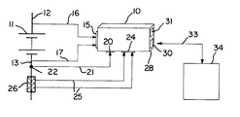
- FIG. 1is a block diagram of a battery monitoring system in accordance with the invention connected to monitor a battery.
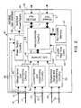
- FIG. 2is a block diagram of a battery monitor apparatus utilized in the system of FIG. 1 .
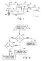
- FIG. 3is a flow chart of the process carried out by the micro-controller within the monitoring apparatus of FIG. 2 to determine the state of the battery.
- FIG. 4is a flow chart illustrating the process carried out by the battery monitoring apparatus of the invention for determining and storing data concerning battery events.
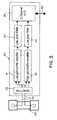
- FIG. 5is a block diagram of a current sensor for utilization in the present invention.
- FIG. 6is a perspective view of a current shunt that may be utilized with a current sensor.
- FIG. 7is a perspective view of a current sensor circuit board mounted to the current shunt of FIG. 6 .
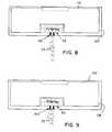
- FIG. 8is a top view of the circuit board of the current sensor of FIG. 7 .
- FIG. 9is a bottom view of the circuit board of the current sensor of FIG. 7 .
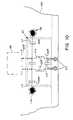
- FIG. 10is a circuit diagram illustrating the effective layout and placement of the filter network in the current sensor of FIG. 7 .
- a battery monitoring apparatus in accordance with the inventionis illustrated at 10 in FIG. 1 connected to monitor the conditions in a battery 11 connected at its positive and negative terminals to conductors 12 and 13 , respectively.
- the battery monitor 10 in accordance with the inventionhas a voltage sense input port 15 which is connected by conducting lines 16 and 17 to the conductors 12 and 13 on either side of the battery to allow the voltage across the battery to be monitored.
- a temperature sense input port 20is connected by a conducting lines 21 to receive a signal from a temperature sensor 22 which is connected to the battery 11 .
- a current sense input port 24is connected by conducting lines 25 to a current sensor 26 which is connected in one of the battery conductors (e.g., the conductor 13 as shown) to detect the level and direction of current flowing through the battery.
- the monitoring apparatus 10has an output port 28 which may include a digital communications port 30 (e.g., an RS-232 port) and an infrared (IrDA) port 31 .
- the data output port 30may be connected via a communications link 33 to a remote system such as a computer 34 , e.g., PC, for periodic communications to and from the battery monitoring apparatus 10 .
- the IrDA port 31allows communication to an IrDA device such as a Palm PilotTM, and other wired and wireless communication links may also be utilized as desired.
- FIG. 2illustrates a block diagram of the battery monitoring apparatus 10 , which may be enclosed in a separate case mounted adjacent to the battery.
- the voltage across the battery provided on the conducting lines 16 and 17 to the input port 15is supplied to a voltage sense and conditioning circuit 40 which provides a conditioned output signal on a line 41 to an analog to digital (A/D) converter 42 .
- the output of the A/D converter 42is supplied on digital data lines 43 to a micro-controller 44 , e.g., a digital signal processor (DSP) chip.
- DSPdigital signal processor
- the power supply circuit 47preferably provides linear or switched regulated power through an isolation transformer to an isolated power supply 48 that provides the power required by the RS-232 port 30 .
- the RS-232 port 30must be isolated from the power supplied to the rest of the monitoring apparatus 10 to provide protection to users who may connect a computer directly to the apparatus 10 through the RS-232 port 30 .
- the signal on the current sense lines 28 received at the current sense input port 24is supplied to a current sense and conditioning circuit 50 , the output of which is supplied on a line 51 to the A/D converter 42 , and the temperature sense signal on the lines 17 is provided through the input port 20 to a temperature sense and condition circuit 53 which provides an output signal on a line 54 to the A/D converter 42 .
- the A/D converter 42supplies output data on the data lines 43 from the sense and conditioning circuits 40 , 50 and 53 to the micro-controller 44 in a controlled manner.
- the sense and conditioning circuits 40 , 50 and 53are preferably formed of amplifier buffer front ends followed by low pass filtering circuits to filter out noise.
- a non-volatile memory 57is connected by data lines 58 to the micro-controller 44 .
- a suitable non-volatile memory 57is an electrically erasable programmable read-only memory (EEPROM). The amount of memory required depends on the number of data points to be stored and the length of time during which data is to be maintained in the monitoring apparatus 10 .
- a clock 60e.g., a crystal oscillator, is utilized to generate a clock signal that is supplied on a line 61 to the micro-controller 44 to establish a time base.
- an exemplary sampling period of the A/D 42 for updating datais 200 msec.
- Examples of commercial components that may be utilizedare: A/D 42 , 12 bit, 4 channel Microchip MCP3204; micro-controller 44 , Microchip flash micro-controller PIC 16LF76; non-volatile memory 57 , EEPROM 32KX8 Microchip 24LC256.
- a particular advantage of the present inventionis that it does not require continuous logging and saving of data concerning battery voltage, temperature and current, which would require a large amount of on-board memory.
- the monitoring apparatus 10implements an activity-based logging routine. This is carried out by assigning the battery three distinct states, namely: (1) open circuit, where the battery is not being charged or discharged and no current (or substantially no current) is flowing through it; (2) a charge state, wherein the battery is being charged by a charger and current is flowing through the battery (from the positive to the negative terminal); and (3) a discharge state, wherein the battery is supplying power to a load (and current is flowing through the battery in a direction from the negative to the positive terminal of the battery).
- a signal corresponding to the battery currentis provided on the lines 28 through the current sense input port 24 and thence through the conditioning circuit 50 and the A/D converter 42 to the micro-controller 44 .
- the data corresponding to the current flowing through the batteryis compared by the micro-controller to a selected threshold level, I th .
- the micro-controlleris programmed to carry out a battery current decision process as illustrated in FIG. 3 . Initially, the battery current I b is read by the micro-controller at 65 , and a decision is made at 66 whether I b is greater than I th .
- the batteryis in the charge state as noted at block 67 ; if no, a decision is then made at 68 whether I b is less than ⁇ I th . If yes, the battery is in the discharge state as indicated at block 69 ; if no, the battery is indicated to be in the open circuit state at block 70 . Thus, the battery is considered to be in an open circuit state if the current through the battery is greater than or equal to ⁇ I th and less than or equal to I th .
- I this preferably selected so that it is less than the normal charge and discharge current, but not at such a low level that minor transient currents that may occur when the battery is in a quiescent state would be recorded as changes to a charge or discharge state when, in fact, charging or discharging is not occurring.
- an activity eventis registered by the micro-controller 44 and a new data record is created and stored in the non-volatile memory 57 .
- the preferred data fields that are tracked and logged (stored) during a given event,are set forth in Table 1 below.
- Table 1illustrates the preferred selected data fields to be saved, which comprise only 12 required fields. Consequently, each record characterizing an event that is stored in the non-volatile memory 57 consists of only 12 data fields, with each data field comprising one or two memory bytes. Although the events may last for hours, only one data field record is saved per event, greatly minimizing the memory requirements for the non-volatile memory 57 while preserving the quality and relevance of the data that is saved.
- a stationary set of finite data fieldsis preferably saved and updated in the non-volatile memory 57 during events.
- the preferred stationary data fieldsare listed in Table 2 below. It is noted that these fields need be created only once and updated during events.
- the monitoring apparatus 10maintains a high sampling rate of data from the voltage, current and temperature sensors so that significant transient events (e.g., maximum voltage) are captured. At each sampling point, the monitoring apparatus reads the battery voltage, current, and temperature and updates the relevant fields. The following summarizes the actions of the monitoring apparatus under control of the micro-controller during this process.
- the monitoring apparatuscontinually monitors the battery current to determine if the state of the battery has changed using the process illustrated in FIG. 3 .
- the Maximum Event Voltage filedis updated with the new voltage reading. Otherwise, the field is unchanged. If the field is updated, the Maximum Event Voltage Time Stamp is also updated.
- the Minimum Event Voltage fieldis updated with the new voltage reading. Otherwise, the field is unchanged.
- the Maximum Event Current fieldis updated with the new current reading. Otherwise, the field is unchanged.
- the Maximum Temperature Current fieldis updated with the new current reading. Otherwise, the field is unchanged.
- the ampere-hour field(current over time) is updated by summing the measured amperes over time.
- the alarm fieldis updated if the battery voltage, current, or temperature exceed preset selected levels. These levels are pre-programmed into the micro-controller 44 as part of the stationary fields listed above in Table 2. If the actual readings exceed the pre-programmed values, an alarm is generated and the alarm field is updated.
- the process carried out by the micro-controller that is summarized aboveis illustrated in the flow diagram of FIG. 4 .
- the programinitiates at 75 by reading the battery voltage, current, and temperature.
- the battery currentis compared with I th at 76 , and if a new battery state is detected, several actions are carried out as indicated in block 77 , including closing the previous data record, updating the total charge and/or discharge amp-hours, total hours of charge/discharge, and open fields, updating the event counter field, creating a new data record, updating the event type field, and updating the start-time field.
- the programthen returns back to a junction 78 and proceeds to block 75 to again the read the battery voltage, current and temperature.
- the amp-hour fieldis updated at 80 , and a comparison of the sampled information is made with minimum and maximum voltage, current and temperature fields at 81 . If the new data do not exceed the minimums and maximums, the program continues by returning back to the junction 78 and then proceeds to again read battery voltage, current and temperature at 75 . If the comparison indicates that minimum or maximum values are exceeded at 81 , the program proceeds to block 83 to update the relevant minimum and maximum voltage, current and temperature fields, and to update the corresponding time stamp, and then continues on to block 84 to compare these readings with setpoints. If the readings do not exceed the setpoints, the program returns to the junction 78 and again reads battery voltage, current and temperature at 75 . If the comparison at 84 indicates the setpoints have been exceeded, the program proceeds to recognize alarms at block 85 .
- the non-volatile memory 57may be formed of two 32K ⁇ 8 EEPROMs, comprising 64K of memory, which allows storage of up to 1362 distinct events. If the battery experiences four events per day, this data storage is sufficient to provide 340 days of storage or nearly a year. Even if the battery experiences 20 events per day, a relatively high activity rate for a normal battery, this still provides 68 days of data storage.
- each recordprovides a detailed characterization of the battery activity during an event.
- the maximum and minimum battery voltagesare provided along with a time stamp for them, and the maximum current and temperature are also provided with their respective time stamps.
- the total amp-hours during the eventis recorded and stored, as well as the overall charge and discharge amp-hours over all events, which is generally the best indication of battery activity.
- the event amp-hour valueis similar to trip miles in an automobile, as it gives users an indication of how much energy was supplied to or from the battery.
- the total amp-hour value of charge and dischargeis similar to an automobile mileage counter and allows users to plan maintenance schedules based on amp-hour usage.
- alarms and faultsare tracked and recorded, allowing users to identify and track abnormal conditions.
- Additional advantagesinclude easy access to data through, e.g., an RS-232 interface or an infrared device such as a Palm PilotTM.
- the saved datais easy to analyze and interpret.
- the monitoring apparatusallows manufacturers to condition battery warranties on the total amp-hours of charge or discharge over the battery life span, rather than simply using a set number of months or years for the term of the warranty. This is a preferred way in which to manage warranties because it relies on actual energy usage and reflects real battery activity.
- Battery leasing companiescan also lease battery systems and bill users based on energy usage (amp-hours) rather than only on time. Time-based leasing and billing does not appropriately compensate leasing companies where the battery is over used and over burdened.
- the present inventionmay also be utilized with a current sensor that is capable of measuring a wide range of current levels with high precision.
- a current shuntis often employed in conventional current sensors to measure the system current, due to the low cost and ease of installation of shunts.
- the current signalsare normally susceptible to both differential and common mode noise. The presence of this noise generally requires additional filtering and noise rejection circuitry to adequately discern actual signal readings from the noise.
- the attainable current reading precisiondepends on the number of bits used. For example, if a 10 bit A/D is employed to measure a 500 A maximum current, the reading resolution is only 0.5 A.
- a higher bit A/Dcan be employed to attain higher resolution.
- the cost of A/Dsincreases with the number of bits.
- a 0.5 A resolutionis quite acceptable during normal charge and discharge cycles, but in many battery applications, and during float charge modes, the current level can be quite low, normally a few hundred milliamps.
- the current reading precisionneeds to be quite high to accurately measure float current levels, preferably less than 10 mA. Even if a 12 bit A/D is employed, the current reading precision will only be 100 mA. This is not enough to accurately measure the float current level.
- the present inventionmay be carried out utilizing a low cost, wide range, and high precision current sensor circuit.
- a shunt 89is connected by leads 25 to a current sensor circuit 90 that includes two current amplifier buffer circuits 91 and 92 , one with low gain and the other with high gain.
- a noise filter 93filters out noise from the signal transmitted from the shunt to the amplifiers 91 and 92 .
- Low pass filtering stages 94 and 95are used to filter out the current readings and provide a level of noise immunity.
- the two analog readingsare then processed by a two-channel A/D 97 which supplies digital data to the monitoring apparatus 10 on data lines 98 , which may be connected to the data lines 43 in the apparatus 10 .
- the monitoring apparatus 10selects among the two digital readouts from the AD 97 based on the current level.
- the current sense and conditioning circuitry 50is not required, and the A/D converter 42 is bypassed for the current sense data signals.
- the current sensor circuit 90may be physically packaged with the other circuitry of FIG. 2, it is preferably located close to the shunt 89 as discussed further below. In this case, digital data is provided to the current sense input port 24 rather than analog signal data. It is understood that the input ports may comprise standard connectors or may simply be openings to admit the signal lines to the enclosure for the battery monitoring apparatus 10 .
- the readout of the low gain stage 91is selected and the full range of A/D converter bits is dedicated to the full-scale current range of the system. Once the current reading drops below a low threshold level, I TH — LOW , the readout of the high gain stage 92 is selected. In this case, the full range of the A/D converter bits is dedicated to a narrower current range with a maximum value of I TH — LOW , thus increasing the precision of low current readouts.
- the shunt 89will produce 50 mV at 500 A.
- the low gain buffer amplifier stage 91has a gain of 82
- the amplified analog current levelwill be 4.1V, which would represent the maximum allowable A/D 97 input voltage level.
- thiswill yield a current accuracy reading of 0.5 A, which is adequate if the current level is above a few amps. This is normally the case during charge and discharge events. If a float charge current needs to be measured with an accuracy of 10 mA, the A/D bits would need to read in 10 mA increments.
- the maximum current that can be measuredwill be 10.24 A.
- the low threshold current level, I TH LOWSis preferably set at 10 A.
- the shunt 89would product 1 mV.
- the high gain buffer amplifier stage 92would need to have a gain of 4100 to yield the maximum allowable A/D input voltage level of 4.1V.
- the monitor 10selects channel 1 (low gain) of the A/D with a reading precision of 0.5 A. Once the current reading drops below 10 A, the monitor 10 selects channel 2 (high gain) of the A/D with a reading precision of 10 mA.
- the high gain amplifier 92would merely saturate.
- the current sense and conditioning circuitry 91 and 92 along with the A/D converter 97are preferably placed on a current sense printed circuit board (PCB) 100 that may be positioned in close proximity to the shunt 89 , as illustrated in FIGS. 6 and 7.
- PCBcurrent sense printed circuit board
- the A/D conversionoccurs on the current sense PCB 100 , which preferably receives the voltage across the shunt at input terminals 102 which are connected by a short twisted pair of leads 25 to the shunt 89 , and digital signals are sent on the data lines 98 to the monitor 10 , greatly improving the quality of the current readout and minimizing noise levels.
- the layout of the current sense PCB 100is important to reducing noise interference and improving the accuracy of the current measurement.
- a layout that is substantially noise immuneis shown in FIGS. 8-10.
- the board 100has a top layer 105 and a bottom layer 108 as shown in FIGS. 8 and 9, respectively.
- the lines 25 carrying the current sense signalare connected via the input terminals 102 to the noise filter 93 which is composed first of a differential mode capacitor 112 , followed by a differential and common mode filter 114 .
- the rest of the analog and digital circuit components 115are placed in the component section on the top layer 105 .
- the bottom layer 108preferably includes a ground plane except under the filter circuitry 100 , to minimize noise.
- the common mode filter capacitors 117are connected directly to the ground plane at connections 118 as the filtered signal enters the processing circuitry. Close and compact placement of the various circuit components is preferred so as to reduce noise and improve circuit noise immunity.
Landscapes
- Physics & Mathematics (AREA)
- General Physics & Mathematics (AREA)
- Secondary Cells (AREA)
- Tests Of Electric Status Of Batteries (AREA)
- Fuses (AREA)
- Charge And Discharge Circuits For Batteries Or The Like (AREA)
Abstract
Description
| TABLE 1 |
| Data record for each event |
| Data Field | Field Stored |
| 1 | Event Type (State)-Open Circuit, Charge, |
| 2 | Event Start Time Stamp- |
| Year:Month:Day:Hour:Minute:Second | |
| 3 | Event Total Ampere Hours |
| 4 | Event Alarms - Voltage, Current or Temperature |
| 5 | Maximum Event Voltage |
| 6 | Maximum Event Voltage Time Stamp-Y:M:D:HH:MM:SS |
| 7 | |
| 8 | Minimum Event Voltage Time Stamp-Y:M:D:HH:MM:SS |
| 9 | |
| 10 | Maximum Event Temperature Time Stamp- |
| Y:M:D:HH:MM: | |
| 11 | |
| 12 | Maximum Event Current Time Stamp-Y:M:D:HH:MM:SS |
| TABLE 2 |
| Stationary data fields |
| Data Field | Field Stored |
| 1 | Installation Time-Y:M:D:HH:MM: |
| 2 | High Voltage Setpoint |
| 3 | Low Voltage Setpoint |
| 4 | High Current Setpoint |
| 5 | High Temperature Setpoint |
| 6 | Battery Nominal Capacity-Ampere Hours |
| 7 | Battery |
| 8 | Cycle Counter |
| 9 | Total hours of open circuit over all |
| 10 | Total hours of discharge over all |
| 11 | Total hours of charge over all |
| 12 | Total Amp Hours of discharge over all |
| 13 | Total Amp Hours of charge over all events |
| 14 | Event Counter-Counts number of events recorded |
Claims (23)
Priority Applications (6)
| Application Number | Priority Date | Filing Date | Title |
|---|---|---|---|
| US10/077,679US6549014B1 (en) | 2002-02-15 | 2002-02-15 | Battery monitoring method and apparatus |
| PCT/US2003/004174WO2003071652A2 (en) | 2002-02-15 | 2003-02-12 | Battery monitoring method and apparatus |
| AU2003219742AAU2003219742A1 (en) | 2002-02-15 | 2003-02-12 | Battery monitoring method and apparatus |
| DE60315268TDE60315268T2 (en) | 2002-02-15 | 2003-02-12 | BATTERY MONITORING PROCESS AND DEVICE |
| EP03716013AEP1485700B1 (en) | 2002-02-15 | 2003-02-12 | Battery monitoring method and apparatus |
| AT03716013TATE368868T1 (en) | 2002-02-15 | 2003-02-12 | BATTERY MONITORING METHOD AND APPARATUS |
Applications Claiming Priority (1)
| Application Number | Priority Date | Filing Date | Title |
|---|---|---|---|
| US10/077,679US6549014B1 (en) | 2002-02-15 | 2002-02-15 | Battery monitoring method and apparatus |
Publications (1)
| Publication Number | Publication Date |
|---|---|
| US6549014B1true US6549014B1 (en) | 2003-04-15 |
Family
ID=22139459
Family Applications (1)
| Application Number | Title | Priority Date | Filing Date |
|---|---|---|---|
| US10/077,679Expired - LifetimeUS6549014B1 (en) | 2002-02-15 | 2002-02-15 | Battery monitoring method and apparatus |
Country Status (6)
| Country | Link |
|---|---|
| US (1) | US6549014B1 (en) |
| EP (1) | EP1485700B1 (en) |
| AT (1) | ATE368868T1 (en) |
| AU (1) | AU2003219742A1 (en) |
| DE (1) | DE60315268T2 (en) |
| WO (1) | WO2003071652A2 (en) |
Cited By (87)
| Publication number | Priority date | Publication date | Assignee | Title |
|---|---|---|---|---|
| US20030053709A1 (en)* | 1999-01-15 | 2003-03-20 | Koninklijke Philips Electronics, N.V. | Coding and noise filtering an image sequence |
| US20030123263A1 (en)* | 2001-12-27 | 2003-07-03 | Caterpillar Inc. | Controller area network using transformers |
| US20040117533A1 (en)* | 2002-12-13 | 2004-06-17 | Ray Fallon | Simplified user interface for UPS monitoring |
| US20040199343A1 (en)* | 2003-04-01 | 2004-10-07 | Cardinal Mark E. | Integrated, self-powered battery monitoring device and system |
| US20050046387A1 (en)* | 2001-11-02 | 2005-03-03 | Aker John F. | Fast charger for high capacity batteries |
| US20050127918A1 (en)* | 2003-12-12 | 2005-06-16 | Kutkut Nasser H. | Activity-based battery monitor with a universal current measuring apparatus |
| US20060012333A1 (en)* | 2004-07-15 | 2006-01-19 | John Houldsworth | One time operating state detecting method and apparatus |
| US20060028173A1 (en)* | 2004-07-22 | 2006-02-09 | Charles Sellers | Battery pack and event monitoring and analysis system and method |
| US20060043797A1 (en)* | 2004-08-31 | 2006-03-02 | American Power Conversion Corporation | Method and apparatus for providing uninterruptible power |
| WO2006094287A2 (en) | 2005-03-04 | 2006-09-08 | Philadelphia Scientific | Device and method for monitoring life history and controlling maintenance of industrial batteries |
| EP1703294A1 (en)* | 2005-03-17 | 2006-09-20 | Shin-Kobe Electric Machinery Co., Ltd. | Battery controller |
| US20070046261A1 (en)* | 2005-08-17 | 2007-03-01 | Wojciech Porebski | Method and apparatus for temperature, conductance and/or impedance testing in remote application of battery monitoring systems |
| US7259572B2 (en) | 2004-06-14 | 2007-08-21 | Powerprecise Solutions, Inc. | Method and apparatus for detecting impedance |
| US20080012427A1 (en)* | 2006-07-13 | 2008-01-17 | Scott Wilson | Power converter with integral battery |
| US20080048616A1 (en)* | 2006-08-24 | 2008-02-28 | Paul Christopher R | System and method for calculating battery state of charge |
| US20080123240A1 (en)* | 2003-05-29 | 2008-05-29 | Nerheim Magne H | Systems and Methods For Immobilization With Repetition Rate Control |
| US20080150491A1 (en)* | 2004-02-25 | 2008-06-26 | Koninklijke Philips Electronics, N.V. | Method Of Estimating The State-Of-Charge And Of The Use Time Left Of A Rechageable Battery, And Apparatus For Executing Such A Method |
| US20080309317A1 (en)* | 2007-06-15 | 2008-12-18 | Lei Chen | Integrated Battery Voltage Sensor with High Voltage Isolation, a Battery Voltage Sensing System and Methods Therefor |
| EP2015090A2 (en) | 2007-07-13 | 2009-01-14 | Honeywell International Inc. | Model-based determination of power source replacement in wireless and other devices |
| US20090033283A1 (en)* | 2007-08-03 | 2009-02-05 | Mirza Akmal Beg | Adjustable battery charger for ups |
| US7510797B2 (en) | 2005-02-24 | 2009-03-31 | Aker Wade Power Technologies, Llc | High capacity battery with integrally-powered cooling assembly |
| US20090210736A1 (en)* | 2008-02-20 | 2009-08-20 | Lonnie Calvin Goff | Multi-function battery monitor system for vehicles |
| US20090228171A1 (en)* | 2008-03-10 | 2009-09-10 | Lonnie Calvin Goff | Battery monitor system attached to a vehicle wiring harness |
| US20090243556A1 (en)* | 2008-03-31 | 2009-10-01 | Vanner, Inc. | System and method for monitoring the state of charge of a battery |
| US20090325044A1 (en)* | 2003-11-18 | 2009-12-31 | Janak Rajpara | Battery assembly with enhanced properties |
| US7651811B2 (en) | 2004-01-28 | 2010-01-26 | Aker Wade Power Technologies, Llc | Thermal management of fast charging high capacity batteries |
| US20100040331A1 (en)* | 2004-09-10 | 2010-02-18 | Adc Telecommunications, Inc. | Hybrid fiber/copper connector system and method |
| US20100174498A1 (en)* | 2009-01-08 | 2010-07-08 | Lonnie Calvin Goff | Battery monitoring algorithms for vehicles |
| WO2010078974A1 (en)* | 2009-01-09 | 2010-07-15 | Robert Bosch Gmbh | Method for controlling an electric vehicle having an auxiliary drive |
| US20100179778A1 (en)* | 2009-01-15 | 2010-07-15 | Lonnie Calvin Goff | Embedded monitoring system for batteries |
| CN101078750B (en)* | 2007-06-28 | 2010-07-28 | 中国科学院电工研究所 | On-board battery monitoring system |
| US20100217551A1 (en)* | 2009-02-25 | 2010-08-26 | Lonnie Calvin Goff | Embedded microprocessor system for vehicular batteries |
| US20100246101A1 (en)* | 2009-03-27 | 2010-09-30 | American Power Conversion Corporation | System and method for altering a user interface of a power device |
| US20100244566A1 (en)* | 2009-03-27 | 2010-09-30 | American Power Conversion Corporation | System and method for configuring a power device |
| US20100244567A1 (en)* | 2009-03-27 | 2010-09-30 | American Power Conversion Corporation | System and method for replacing a battery in an uninterruptible power supply |
| US20100250192A1 (en)* | 2009-03-27 | 2010-09-30 | American Power Conversion Corporation | System and method for estimating an efficiency of a power device |
| US20100244571A1 (en)* | 2009-03-27 | 2010-09-30 | American Power Conversion Corporation | System and method for changing power states of a power device |
| US20100292942A1 (en)* | 2009-05-18 | 2010-11-18 | Lonnie Calvin Golf | Embedded algorithms for vehicular batteries |
| US20100305812A1 (en)* | 2009-05-26 | 2010-12-02 | Toyota Jidosha Kabushiki Kaisha | Event information collecting system for vehicle and method for collecting event information on vehicle |
| US20110006737A1 (en)* | 2009-07-10 | 2011-01-13 | Narayana Prakash Saligram | Battery charging method and apparatus |
| US20110029193A1 (en)* | 2009-07-31 | 2011-02-03 | Thermo King Corporation | Monitoring battery health in an hvac system |
| CN101312293B (en)* | 2007-05-22 | 2011-02-16 | 深圳市金一泰实业有限公司 | Power lithium battery intelligent management system |
| US20110043393A1 (en)* | 2009-08-21 | 2011-02-24 | Denso Corporation | Device for converting analog signal into digital values and correcting the values |
| US20110048485A1 (en)* | 2009-09-02 | 2011-03-03 | Lonnie Calvin Goff | Integrated battery management system for vehicles |
| US20110050177A1 (en)* | 2003-02-11 | 2011-03-03 | Taser International, Inc. | Systems and methods for predicting remaining battery capacity |
| US20110156648A1 (en)* | 2009-12-28 | 2011-06-30 | Lonnie Calvin Goff | Integrated cell balancing system for multi-cell batteries |
| CN102150057A (en)* | 2008-08-25 | 2011-08-10 | 罗伯特.博世有限公司 | Monitoring system for an accumulator |
| US20110248841A1 (en)* | 2008-04-30 | 2011-10-13 | Tracker Network (Uk) Limited | Vehicle engine operation |
| US20120029852A1 (en)* | 2008-02-20 | 2012-02-02 | Goff Lonnie C | Battery monitor system attached to a vehicle wiring harness |
| US20120092180A1 (en)* | 2010-05-14 | 2012-04-19 | Michael Rikkola | Predictive analysis for remote machine monitoring |
| US8198863B1 (en) | 2006-12-13 | 2012-06-12 | Maxim Integrated Products, Inc. | Model-based battery fuel gauges and methods |
| US8203305B1 (en) | 2008-07-02 | 2012-06-19 | Maxim Integrated Products, Inc. | Enhanced voltage-based fuel gauges and methods |
| US20120235483A1 (en)* | 2011-03-18 | 2012-09-20 | Johnson Controls Technology Llc | Battery power source control and current detection systems and methods |
| CN102830360A (en)* | 2012-08-22 | 2012-12-19 | 杭州杰能动力有限公司 | Method and system for acquiring real-time battery capacity in motion of car and electric car |
| US20130059220A1 (en)* | 2011-09-07 | 2013-03-07 | Dong-rak KIM | Fuel cell system and driving method thereof |
| US20130106356A1 (en)* | 2010-06-28 | 2013-05-02 | Hitachi Vehicle Energy, Ltd. | Battery control circuit and battery device |
| US20130127611A1 (en)* | 2011-11-20 | 2013-05-23 | Battery Marvel, Llc. | Battery marvel 1.0 |
| CN103235265A (en)* | 2013-03-29 | 2013-08-07 | 国家电网公司 | Online power battery parameter detecting system and detecting method thereof |
| US20130235902A1 (en)* | 2012-03-07 | 2013-09-12 | Apple Inc. | Communication and monitoring of a battery via a single wire |
| EP1798838A3 (en)* | 2005-12-19 | 2013-10-02 | O2Micro, Inc. | Low pass filter |
| WO2013144617A1 (en)* | 2012-03-30 | 2013-10-03 | Lifescan Scotland Limited | Battery status detection and storage method and system in medical monitoring |
| US20130278221A1 (en)* | 2010-12-28 | 2013-10-24 | Reizo Maeda | Method of detecting battery degradation level |
| US8639953B2 (en) | 2009-03-27 | 2014-01-28 | Schneider Electric It Corporation | System and method for gathering information using a power device wherein information is associated with at least one external load |
| US20140084867A1 (en)* | 2012-09-24 | 2014-03-27 | Kabushiki Kaisha Toshiba | Secondary battery device and battery capacity estimation system |
| DE102012222726A1 (en)* | 2012-12-11 | 2014-06-12 | Robert Bosch Gmbh | Method for monitoring current of battery cell, involves forming current comparison value using battery cell current and filter, and comparing current comparison value with predetermined limiting reference value |
| US20140167974A1 (en)* | 2012-12-17 | 2014-06-19 | Itron, Inc. | Metrology with universal serial bus (usb) connection |
| US20140167656A1 (en)* | 2011-08-30 | 2014-06-19 | Sanyo Electric Co., Ltd. | Battery system, electric vehicle, movable body, power storage device, and power supply device |
| CN104035046A (en)* | 2014-06-11 | 2014-09-10 | 长沙勤凯机电科技有限公司 | Vehicle-mounted storage battery online monitoring system |
| EP2806482A1 (en)* | 2009-09-28 | 2014-11-26 | Hitachi, Ltd. | Battery system |
| US20150077089A1 (en)* | 2013-09-13 | 2015-03-19 | Alps Electric Co., Ltd. | Voltage detection device |
| US9035616B2 (en) | 2010-12-07 | 2015-05-19 | Maxim Integrated Products, Inc. | State based full and empty control for rechargeable batteries |
| WO2015169717A1 (en)* | 2014-05-05 | 2015-11-12 | Siemens Aktiengesellschaft | Detecting the operational management of a battery store |
| US20160124029A1 (en)* | 2014-11-04 | 2016-05-05 | Stmicroelectronics S.R.L. | Detection circuit for an active discharge circuit of an x-capacitor, related active discharge circuit, integrated circuit and method |
| US9513339B2 (en) | 2012-05-31 | 2016-12-06 | Analog Devices, Inc. | Device and method for equalizing current drain from a battery stack |
| US20170070166A1 (en)* | 2015-09-04 | 2017-03-09 | Schneider Electric Industries Sas | Soft starting system for an electrical motor |
| US9599519B2 (en) | 2012-03-07 | 2017-03-21 | Apple Inc. | Charging a battery based on stored battery characteristics |
| US9664745B1 (en) | 2013-06-07 | 2017-05-30 | Material Handling Services, LLC | Computer implemented system and method and computer program product for using battery information to automatically charge a battery |
| EP2616267B1 (en)* | 2010-09-14 | 2019-06-19 | Robert Bosch GmbH | Battery having cell voltage and battery current detection and comprising only one electrical isolation device |
| US20190339304A1 (en)* | 2016-03-03 | 2019-11-07 | Kongsberg Inc. | Circuit And Method For Shunt Current Sensing |
| DE102011000661B4 (en)* | 2010-02-12 | 2019-11-14 | Denso Corporation | current sensor |
| US10770914B2 (en) | 2018-11-05 | 2020-09-08 | C.E. Niehoff & Co. | Dual control loop for charging of batteries |
| US20210166502A1 (en)* | 2018-09-18 | 2021-06-03 | Cambridge Mobile Telematics Inc. | Using vehicle electrical system monitored values |
| US11275119B2 (en) | 2019-09-13 | 2022-03-15 | Semiconductor Components Industries, Llc | Methods and system for a battery |
| WO2022159697A1 (en)* | 2021-01-22 | 2022-07-28 | Google Llc | Systems and methods for monitoring high charge levels in rechargeable batteries |
| US20220239134A1 (en)* | 2021-01-22 | 2022-07-28 | Google Llc | Systems and methods for monitoring high charge levels in rechargeable batteries |
| US11604229B2 (en) | 2020-12-28 | 2023-03-14 | Analog Devices International Unlimited Company | Techniques for determining energy storage device state of health |
| US11811248B2 (en) | 2016-07-21 | 2023-11-07 | C.E. Niehoff & Co. | Vehicle generator using battery charging profiles |
Families Citing this family (2)
| Publication number | Priority date | Publication date | Assignee | Title |
|---|---|---|---|---|
| US10921353B2 (en) | 2016-08-13 | 2021-02-16 | Andrew J. Borleske | Systems, devices, and methods for a wide dynamic range current measurement with consumption event analysis |
| DE102017212728A1 (en)* | 2017-07-25 | 2019-01-31 | Continental Teves Ag & Co. Ohg | Data recorder for vehicles with at least one battery |
Citations (18)
| Publication number | Priority date | Publication date | Assignee | Title |
|---|---|---|---|---|
| US3979657A (en) | 1973-05-15 | 1976-09-07 | Westinghouse Electric Corporation | Battery monitor with automatic scale and recycle prevents |
| US4316185A (en) | 1980-07-17 | 1982-02-16 | General Electric Company | Battery monitor circuit |
| US4387334A (en) | 1981-06-05 | 1983-06-07 | Rockwell International Corporation | Battery monitor circuit |
| US4929931A (en) | 1988-12-22 | 1990-05-29 | Honeywell Inc. | Battery monitor |
| US4990885A (en) | 1989-10-11 | 1991-02-05 | Navistar International Transportation Corp. | Auxiliary battery monitor |
| US5095274A (en) | 1989-09-22 | 1992-03-10 | Analog Devices, Inc. | Temperature-compensated apparatus for monitoring current having controlled sensitivity to supply voltage |
| US5130659A (en) | 1990-08-21 | 1992-07-14 | Sloan Jeffrey M | Battery Monitor |
| US5179340A (en) | 1988-07-13 | 1993-01-12 | Electronic Development Incorporated | Apparatus for monitoring the state of charge of a battery |
| US5394089A (en) | 1988-07-21 | 1995-02-28 | Opalport Electronics Limited | Battery monitor which indicates remaining capacity by continuously monitoring instantaneous power consumption relative to expected hyperbolic discharge rates |
| US5646534A (en) | 1995-01-06 | 1997-07-08 | Chrysler Corporation | Battery monitor for electric vehicles |
| US5886503A (en) | 1996-05-29 | 1999-03-23 | Peco Ii, Inc. | Back-up battery management apparatus for charging and testing individual battery cells in a string of battery cells |
| US5895440A (en) | 1996-12-23 | 1999-04-20 | Cruising Equipment Company, Inc. | Battery monitor and cycle status indicator |
| US6037749A (en) | 1995-06-21 | 2000-03-14 | Batteryguard Limited | Battery monitor |
| US6118384A (en) | 1995-12-29 | 2000-09-12 | Advanced Micro Devices, Inc. | Battery monitor with software trim |
| US6150795A (en) | 1999-11-05 | 2000-11-21 | Power Designers, Llc | Modular battery charge equalizers and method of control |
| US6222370B1 (en) | 1998-03-13 | 2001-04-24 | Brian Walter Schousek | Universal battery monitor |
| US6268710B1 (en) | 1999-07-09 | 2001-07-31 | Fujitsu Limited | Battery monitor apparatus |
| US6304062B1 (en) | 1999-10-28 | 2001-10-16 | Powersmart, Inc. | Shunt resistance device for monitoring battery state of charge |
Family Cites Families (3)
| Publication number | Priority date | Publication date | Assignee | Title |
|---|---|---|---|---|
| WO1997015839A1 (en)* | 1995-10-27 | 1997-05-01 | Globe-Union, Inc. | Battery monitor and method |
| JP3524661B2 (en)* | 1995-12-08 | 2004-05-10 | 本田技研工業株式会社 | Power control device for electric vehicle |
| AUPP110497A0 (en)* | 1997-12-23 | 1998-01-22 | Telstra Corporation Limited | Electrical parameter monitoring system |
- 2002
- 2002-02-15USUS10/077,679patent/US6549014B1/ennot_activeExpired - Lifetime
- 2003
- 2003-02-12EPEP03716013Apatent/EP1485700B1/ennot_activeExpired - Lifetime
- 2003-02-12ATAT03716013Tpatent/ATE368868T1/ennot_activeIP Right Cessation
- 2003-02-12WOPCT/US2003/004174patent/WO2003071652A2/enactiveIP Right Grant
- 2003-02-12DEDE60315268Tpatent/DE60315268T2/ennot_activeExpired - Fee Related
- 2003-02-12AUAU2003219742Apatent/AU2003219742A1/ennot_activeAbandoned
Patent Citations (19)
| Publication number | Priority date | Publication date | Assignee | Title |
|---|---|---|---|---|
| US3979657A (en) | 1973-05-15 | 1976-09-07 | Westinghouse Electric Corporation | Battery monitor with automatic scale and recycle prevents |
| US4316185A (en) | 1980-07-17 | 1982-02-16 | General Electric Company | Battery monitor circuit |
| US4387334A (en) | 1981-06-05 | 1983-06-07 | Rockwell International Corporation | Battery monitor circuit |
| US5179340A (en) | 1988-07-13 | 1993-01-12 | Electronic Development Incorporated | Apparatus for monitoring the state of charge of a battery |
| US5394089A (en) | 1988-07-21 | 1995-02-28 | Opalport Electronics Limited | Battery monitor which indicates remaining capacity by continuously monitoring instantaneous power consumption relative to expected hyperbolic discharge rates |
| US4929931A (en) | 1988-12-22 | 1990-05-29 | Honeywell Inc. | Battery monitor |
| US5095274A (en) | 1989-09-22 | 1992-03-10 | Analog Devices, Inc. | Temperature-compensated apparatus for monitoring current having controlled sensitivity to supply voltage |
| US4990885A (en) | 1989-10-11 | 1991-02-05 | Navistar International Transportation Corp. | Auxiliary battery monitor |
| US5130659A (en) | 1990-08-21 | 1992-07-14 | Sloan Jeffrey M | Battery Monitor |
| US5646534A (en) | 1995-01-06 | 1997-07-08 | Chrysler Corporation | Battery monitor for electric vehicles |
| US5808469A (en) | 1995-01-06 | 1998-09-15 | Chrysler Corporation | Battery monitor for electric vehicles |
| US6037749A (en) | 1995-06-21 | 2000-03-14 | Batteryguard Limited | Battery monitor |
| US6118384A (en) | 1995-12-29 | 2000-09-12 | Advanced Micro Devices, Inc. | Battery monitor with software trim |
| US5886503A (en) | 1996-05-29 | 1999-03-23 | Peco Ii, Inc. | Back-up battery management apparatus for charging and testing individual battery cells in a string of battery cells |
| US5895440A (en) | 1996-12-23 | 1999-04-20 | Cruising Equipment Company, Inc. | Battery monitor and cycle status indicator |
| US6222370B1 (en) | 1998-03-13 | 2001-04-24 | Brian Walter Schousek | Universal battery monitor |
| US6268710B1 (en) | 1999-07-09 | 2001-07-31 | Fujitsu Limited | Battery monitor apparatus |
| US6304062B1 (en) | 1999-10-28 | 2001-10-16 | Powersmart, Inc. | Shunt resistance device for monitoring battery state of charge |
| US6150795A (en) | 1999-11-05 | 2000-11-21 | Power Designers, Llc | Modular battery charge equalizers and method of control |
Cited By (168)
| Publication number | Priority date | Publication date | Assignee | Title |
|---|---|---|---|---|
| US6993195B2 (en)* | 1999-01-15 | 2006-01-31 | Koninklijke Philips Electronics N.V. | Coding and noise filtering an image sequence |
| US20030053709A1 (en)* | 1999-01-15 | 2003-03-20 | Koninklijke Philips Electronics, N.V. | Coding and noise filtering an image sequence |
| US20050046387A1 (en)* | 2001-11-02 | 2005-03-03 | Aker John F. | Fast charger for high capacity batteries |
| US7301308B2 (en) | 2001-11-02 | 2007-11-27 | Aker Wade Power Technologies, Llc | Fast charger for high capacity batteries |
| US7065152B2 (en)* | 2001-12-27 | 2006-06-20 | Caterpillar Inc. | Controller area network using transformers |
| US20030123263A1 (en)* | 2001-12-27 | 2003-07-03 | Caterpillar Inc. | Controller area network using transformers |
| US20040117533A1 (en)* | 2002-12-13 | 2004-06-17 | Ray Fallon | Simplified user interface for UPS monitoring |
| US20110050177A1 (en)* | 2003-02-11 | 2011-03-03 | Taser International, Inc. | Systems and methods for predicting remaining battery capacity |
| US8045316B2 (en) | 2003-02-11 | 2011-10-25 | Taser International, Inc. | Systems and methods for predicting remaining battery capacity |
| US6915220B2 (en)* | 2003-04-01 | 2005-07-05 | General Electric Company | Integrated, self-powered battery monitoring device and system |
| US20040199343A1 (en)* | 2003-04-01 | 2004-10-07 | Cardinal Mark E. | Integrated, self-powered battery monitoring device and system |
| US7580237B2 (en) | 2003-05-29 | 2009-08-25 | Taser International, Inc. | Systems and methods for immobilization with repetition rate control |
| US7570476B2 (en) | 2003-05-29 | 2009-08-04 | Taser International, Inc. | Systems and methods for an electronic control device with date and time recording |
| US20080123240A1 (en)* | 2003-05-29 | 2008-05-29 | Nerheim Magne H | Systems and Methods For Immobilization With Repetition Rate Control |
| US20080130193A1 (en)* | 2003-05-29 | 2008-06-05 | Nerheim Magne H | Systems And Methods For An Electronic Control Device With Date And Time Recording |
| US9257726B2 (en) | 2003-11-18 | 2016-02-09 | Teledyne Technologies Incorporated | Battery assembly with enhanced properties |
| US20090325044A1 (en)* | 2003-11-18 | 2009-12-31 | Janak Rajpara | Battery assembly with enhanced properties |
| US7791347B2 (en)* | 2003-11-18 | 2010-09-07 | Teledyne Technologies Incorporated | Battery assembly with enhanced properties |
| US20050127918A1 (en)* | 2003-12-12 | 2005-06-16 | Kutkut Nasser H. | Activity-based battery monitor with a universal current measuring apparatus |
| US7173429B2 (en)* | 2003-12-12 | 2007-02-06 | Power Designers, Llc | Activity-based battery monitor with a universal current measuring apparatus |
| US7651811B2 (en) | 2004-01-28 | 2010-01-26 | Aker Wade Power Technologies, Llc | Thermal management of fast charging high capacity batteries |
| US20080150491A1 (en)* | 2004-02-25 | 2008-06-26 | Koninklijke Philips Electronics, N.V. | Method Of Estimating The State-Of-Charge And Of The Use Time Left Of A Rechageable Battery, And Apparatus For Executing Such A Method |
| US7259572B2 (en) | 2004-06-14 | 2007-08-21 | Powerprecise Solutions, Inc. | Method and apparatus for detecting impedance |
| US7589533B2 (en)* | 2004-07-15 | 2009-09-15 | Texas Instruments Northern Virginia Incorporated | One time operating state detecting method and apparatus |
| US7248053B2 (en)* | 2004-07-15 | 2007-07-24 | Powerprecise Solutions, Inc. | One time operating state detecting method and apparatus |
| US20070052422A1 (en)* | 2004-07-15 | 2007-03-08 | John Houldsworth | One time operating state detecting method and apparatus |
| US20060012333A1 (en)* | 2004-07-15 | 2006-01-19 | John Houldsworth | One time operating state detecting method and apparatus |
| US7518336B2 (en)* | 2004-07-22 | 2009-04-14 | Helwett-Packard Development Company, L.P. | Battery pack event-proof monitoring and analysis system and method |
| US20060028173A1 (en)* | 2004-07-22 | 2006-02-09 | Charles Sellers | Battery pack and event monitoring and analysis system and method |
| US8053927B2 (en) | 2004-08-31 | 2011-11-08 | American Power Conversion Corporation | Method and apparatus for providing uninterruptible power |
| US20060043797A1 (en)* | 2004-08-31 | 2006-03-02 | American Power Conversion Corporation | Method and apparatus for providing uninterruptible power |
| US20100225170A1 (en)* | 2004-08-31 | 2010-09-09 | American Power Conversion Corporation | Method and apparatus for providing uninterruptible power |
| US20110227415A1 (en)* | 2004-08-31 | 2011-09-22 | American Power Conversion Corporation | Method and apparatus for providing uninterruptible power |
| US7737580B2 (en)* | 2004-08-31 | 2010-06-15 | American Power Conversion Corporation | Method and apparatus for providing uninterruptible power |
| US7855472B2 (en) | 2004-08-31 | 2010-12-21 | American Power Conversion Corporation | Method and apparatus for providing uninterruptible power |
| US20100040331A1 (en)* | 2004-09-10 | 2010-02-18 | Adc Telecommunications, Inc. | Hybrid fiber/copper connector system and method |
| US7510797B2 (en) | 2005-02-24 | 2009-03-31 | Aker Wade Power Technologies, Llc | High capacity battery with integrally-powered cooling assembly |
| WO2006094287A2 (en) | 2005-03-04 | 2006-09-08 | Philadelphia Scientific | Device and method for monitoring life history and controlling maintenance of industrial batteries |
| US8482258B2 (en) | 2005-03-04 | 2013-07-09 | Philadelphia Scientific Llc | Device and method for monitoring life history and controlling maintenance of industrial batteries |
| US20060208693A1 (en)* | 2005-03-17 | 2006-09-21 | Akihiko Emori | Battery controller |
| CN100391083C (en)* | 2005-03-17 | 2008-05-28 | 新神户电机株式会社 | battery controller |
| EP1703294A1 (en)* | 2005-03-17 | 2006-09-20 | Shin-Kobe Electric Machinery Co., Ltd. | Battery controller |
| US20070046261A1 (en)* | 2005-08-17 | 2007-03-01 | Wojciech Porebski | Method and apparatus for temperature, conductance and/or impedance testing in remote application of battery monitoring systems |
| EP1798838A3 (en)* | 2005-12-19 | 2013-10-02 | O2Micro, Inc. | Low pass filter |
| US20080012427A1 (en)* | 2006-07-13 | 2008-01-17 | Scott Wilson | Power converter with integral battery |
| US7446505B2 (en)* | 2006-08-24 | 2008-11-04 | Symbol Technologies, Inc. | System and method for calculating a state of charge of a battery |
| US20080048616A1 (en)* | 2006-08-24 | 2008-02-28 | Paul Christopher R | System and method for calculating battery state of charge |
| US8198863B1 (en) | 2006-12-13 | 2012-06-12 | Maxim Integrated Products, Inc. | Model-based battery fuel gauges and methods |
| US8502504B1 (en) | 2006-12-13 | 2013-08-06 | Maxim Integrated Products, Inc. | Model-based battery fuel gauges and methods |
| CN101312293B (en)* | 2007-05-22 | 2011-02-16 | 深圳市金一泰实业有限公司 | Power lithium battery intelligent management system |
| US20080309317A1 (en)* | 2007-06-15 | 2008-12-18 | Lei Chen | Integrated Battery Voltage Sensor with High Voltage Isolation, a Battery Voltage Sensing System and Methods Therefor |
| US7876071B2 (en)* | 2007-06-15 | 2011-01-25 | Avago Technologies Ecbu Ip (Singapore) Pte. Ltd. | Integrated battery voltage sensor with high voltage isolation, a battery voltage sensing system and methods therefor |
| CN101078750B (en)* | 2007-06-28 | 2010-07-28 | 中国科学院电工研究所 | On-board battery monitoring system |
| EP2015090A3 (en)* | 2007-07-13 | 2014-01-15 | Honeywell International Inc. | Model-based determination of power source replacement in wireless and other devices |
| EP2015090A2 (en) | 2007-07-13 | 2009-01-14 | Honeywell International Inc. | Model-based determination of power source replacement in wireless and other devices |
| US7944182B2 (en) | 2007-08-03 | 2011-05-17 | American Power Conversion Corporation | Adjustable battery charger for UPS |
| US20090033283A1 (en)* | 2007-08-03 | 2009-02-05 | Mirza Akmal Beg | Adjustable battery charger for ups |
| US20120029852A1 (en)* | 2008-02-20 | 2012-02-02 | Goff Lonnie C | Battery monitor system attached to a vehicle wiring harness |
| US20090210736A1 (en)* | 2008-02-20 | 2009-08-20 | Lonnie Calvin Goff | Multi-function battery monitor system for vehicles |
| US8437908B2 (en)* | 2008-03-10 | 2013-05-07 | 4 Peaks Technology Llc | Battery monitor system attached to a vehicle wiring harness |
| US20090228171A1 (en)* | 2008-03-10 | 2009-09-10 | Lonnie Calvin Goff | Battery monitor system attached to a vehicle wiring harness |
| WO2009151737A1 (en)* | 2008-03-31 | 2009-12-17 | Vanner, Inc. | System and method for monitoring the state of charge of a battery |
| US8154252B2 (en)* | 2008-03-31 | 2012-04-10 | Vanner, Inc. | System and method for monitoring the state of charge of a battery |
| US20090243556A1 (en)* | 2008-03-31 | 2009-10-01 | Vanner, Inc. | System and method for monitoring the state of charge of a battery |
| US9643570B2 (en)* | 2008-04-30 | 2017-05-09 | Tracker Network (Uk) Limited | Vehicle engine operation |
| US20190389425A1 (en)* | 2008-04-30 | 2019-12-26 | Tracker Network (Uk) Limited | Vehicle engine operation |
| US10807562B2 (en)* | 2008-04-30 | 2020-10-20 | Tracker Network (Uk) Limited | Vehicle engine operation |
| US10272874B2 (en) | 2008-04-30 | 2019-04-30 | Tracker Network (Uk) Limited | Vehicle engine operation |
| US11618411B2 (en) | 2008-04-30 | 2023-04-04 | Tracker Network (Uk) Limited | Vehicle engine operation |
| US20110248841A1 (en)* | 2008-04-30 | 2011-10-13 | Tracker Network (Uk) Limited | Vehicle engine operation |
| US8203305B1 (en) | 2008-07-02 | 2012-06-19 | Maxim Integrated Products, Inc. | Enhanced voltage-based fuel gauges and methods |
| US8643331B1 (en) | 2008-07-02 | 2014-02-04 | Maxim Integrated Products, Inc. | Enhanced voltage-based fuel gauges and methods |
| US20110313696A1 (en)* | 2008-08-25 | 2011-12-22 | Michael Wolf | Battery monitoring system |
| US9660303B2 (en)* | 2008-08-25 | 2017-05-23 | Robert Bosch Gmbh | Battery monitoring system |
| CN102150057B (en)* | 2008-08-25 | 2015-04-01 | 罗伯特.博世有限公司 | Monitoring system for an accumulator |
| CN102150057A (en)* | 2008-08-25 | 2011-08-10 | 罗伯特.博世有限公司 | Monitoring system for an accumulator |
| US20100174498A1 (en)* | 2009-01-08 | 2010-07-08 | Lonnie Calvin Goff | Battery monitoring algorithms for vehicles |
| US8386199B2 (en) | 2009-01-08 | 2013-02-26 | 4 Peaks Technology Llc | Battery monitoring algorithms for vehicles |
| WO2010078974A1 (en)* | 2009-01-09 | 2010-07-15 | Robert Bosch Gmbh | Method for controlling an electric vehicle having an auxiliary drive |
| US20100179778A1 (en)* | 2009-01-15 | 2010-07-15 | Lonnie Calvin Goff | Embedded monitoring system for batteries |
| US20100217551A1 (en)* | 2009-02-25 | 2010-08-26 | Lonnie Calvin Goff | Embedded microprocessor system for vehicular batteries |
| US20100244567A1 (en)* | 2009-03-27 | 2010-09-30 | American Power Conversion Corporation | System and method for replacing a battery in an uninterruptible power supply |
| US20100250192A1 (en)* | 2009-03-27 | 2010-09-30 | American Power Conversion Corporation | System and method for estimating an efficiency of a power device |
| US9595742B2 (en) | 2009-03-27 | 2017-03-14 | Schneider Electric It Corporation | System and method for replacing a battery in an uninterruptible power supply |
| US9231439B2 (en) | 2009-03-27 | 2016-01-05 | Schneider Electric It Corporation | System and method for estimating an efficiency of a power device |
| US20100244566A1 (en)* | 2009-03-27 | 2010-09-30 | American Power Conversion Corporation | System and method for configuring a power device |
| US8639953B2 (en) | 2009-03-27 | 2014-01-28 | Schneider Electric It Corporation | System and method for gathering information using a power device wherein information is associated with at least one external load |
| US20100246101A1 (en)* | 2009-03-27 | 2010-09-30 | American Power Conversion Corporation | System and method for altering a user interface of a power device |
| US8386809B2 (en) | 2009-03-27 | 2013-02-26 | Schneider Electric It Corporation | System and method for configuring a power device |
| US8476787B2 (en) | 2009-03-27 | 2013-07-02 | Schneider Electric It Corporation | System and method for changing power states of a power device |
| US20100244571A1 (en)* | 2009-03-27 | 2010-09-30 | American Power Conversion Corporation | System and method for changing power states of a power device |
| US8732602B2 (en) | 2009-03-27 | 2014-05-20 | Schneider Electric It Corporation | System and method for altering a user interface of a power device |
| US20100292942A1 (en)* | 2009-05-18 | 2010-11-18 | Lonnie Calvin Golf | Embedded algorithms for vehicular batteries |
| US20100305812A1 (en)* | 2009-05-26 | 2010-12-02 | Toyota Jidosha Kabushiki Kaisha | Event information collecting system for vehicle and method for collecting event information on vehicle |
| US9202320B2 (en)* | 2009-05-26 | 2015-12-01 | Toyota Jidosha Kabushiki Kaisha | Event information collecting system for vehicle and method for collecting event information on vehicle |
| US8581554B2 (en) | 2009-07-10 | 2013-11-12 | Schneider Electric It Corporation | Battery charging method and apparatus |
| US20110006737A1 (en)* | 2009-07-10 | 2011-01-13 | Narayana Prakash Saligram | Battery charging method and apparatus |
| US8423238B2 (en) | 2009-07-31 | 2013-04-16 | Thermo King Corporation | Monitoring battery health in an HVAC system |
| US20110029193A1 (en)* | 2009-07-31 | 2011-02-03 | Thermo King Corporation | Monitoring battery health in an hvac system |
| US20110043393A1 (en)* | 2009-08-21 | 2011-02-24 | Denso Corporation | Device for converting analog signal into digital values and correcting the values |
| US8134485B2 (en)* | 2009-08-21 | 2012-03-13 | Denso Corporation | Device for converting analog signal into digital values and correcting the values |
| US20110048485A1 (en)* | 2009-09-02 | 2011-03-03 | Lonnie Calvin Goff | Integrated battery management system for vehicles |
| EP2806482A1 (en)* | 2009-09-28 | 2014-11-26 | Hitachi, Ltd. | Battery system |
| US9203248B2 (en) | 2009-09-28 | 2015-12-01 | Hitachi, Ltd. | Battery management system using non-volatile memory |
| US20110156648A1 (en)* | 2009-12-28 | 2011-06-30 | Lonnie Calvin Goff | Integrated cell balancing system for multi-cell batteries |
| US8581548B2 (en) | 2009-12-28 | 2013-11-12 | 4 Peak Technology LLC | Integrated cell balancing system, method, and computer program for multi-cell batteries |
| DE102011000661B4 (en)* | 2010-02-12 | 2019-11-14 | Denso Corporation | current sensor |
| US20120092180A1 (en)* | 2010-05-14 | 2012-04-19 | Michael Rikkola | Predictive analysis for remote machine monitoring |
| US8838417B2 (en) | 2010-05-14 | 2014-09-16 | Harnischfeger Technologies, Inc | Cycle decomposition analysis for remote machine monitoring |
| US9971346B2 (en) | 2010-05-14 | 2018-05-15 | Harnischfeger Technologies, Inc. | Remote monitoring of machine alarms |
| US11092951B2 (en) | 2010-05-14 | 2021-08-17 | Joy Global Surface Mining Inc | Method and system for predicting failure of mining machine crowd system |
| US9372482B2 (en)* | 2010-05-14 | 2016-06-21 | Harnischfeger Technologies, Inc. | Predictive analysis for remote machine monitoring |
| US9362759B2 (en)* | 2010-06-28 | 2016-06-07 | Hitachi Vehicle Energy, Ltd. | Battery control circuit and battery device |
| US20130106356A1 (en)* | 2010-06-28 | 2013-05-02 | Hitachi Vehicle Energy, Ltd. | Battery control circuit and battery device |
| EP2616267B1 (en)* | 2010-09-14 | 2019-06-19 | Robert Bosch GmbH | Battery having cell voltage and battery current detection and comprising only one electrical isolation device |
| US9791517B2 (en) | 2010-12-07 | 2017-10-17 | Maxim Integrated Products, Inc. | State based full and empty control for rechargeable batteries |
| US10139452B2 (en) | 2010-12-07 | 2018-11-27 | Maxim Integraqted Products, Inc. | State based full and empty control for rechargeable batteries |
| US9035616B2 (en) | 2010-12-07 | 2015-05-19 | Maxim Integrated Products, Inc. | State based full and empty control for rechargeable batteries |
| US20130278221A1 (en)* | 2010-12-28 | 2013-10-24 | Reizo Maeda | Method of detecting battery degradation level |
| US20120235483A1 (en)* | 2011-03-18 | 2012-09-20 | Johnson Controls Technology Llc | Battery power source control and current detection systems and methods |
| US10044074B2 (en)* | 2011-03-18 | 2018-08-07 | Johnson Controls Technology Company | Battery power source control and current detection systems and methods |
| CN103703605A (en)* | 2011-03-18 | 2014-04-02 | 约翰逊控制技术有限责任公司 | Battery power source control and current detection system and method |
| US9529051B2 (en)* | 2011-08-30 | 2016-12-27 | Sanyo Electric Co., Ltd. | Battery system, electric vehicle, movable body, power storage device, and power supply device |
| US20140167656A1 (en)* | 2011-08-30 | 2014-06-19 | Sanyo Electric Co., Ltd. | Battery system, electric vehicle, movable body, power storage device, and power supply device |
| US20130059220A1 (en)* | 2011-09-07 | 2013-03-07 | Dong-rak KIM | Fuel cell system and driving method thereof |
| US20130127611A1 (en)* | 2011-11-20 | 2013-05-23 | Battery Marvel, Llc. | Battery marvel 1.0 |
| US9599519B2 (en) | 2012-03-07 | 2017-03-21 | Apple Inc. | Charging a battery based on stored battery characteristics |
| US9797784B2 (en)* | 2012-03-07 | 2017-10-24 | Apple Inc. | Communication and monitoring of a battery via a single wire |
| US20130235902A1 (en)* | 2012-03-07 | 2013-09-12 | Apple Inc. | Communication and monitoring of a battery via a single wire |
| CN104203097B (en)* | 2012-03-30 | 2017-10-24 | 生命扫描苏格兰有限公司 | Battery status detection and storage method and system in medical monitoring |
| WO2013144617A1 (en)* | 2012-03-30 | 2013-10-03 | Lifescan Scotland Limited | Battery status detection and storage method and system in medical monitoring |
| US9728818B2 (en) | 2012-03-30 | 2017-08-08 | Lifescan Scotland Limited | Battery status detection and storage method and system in medical monitoring |
| CN104203097A (en)* | 2012-03-30 | 2014-12-10 | 生命扫描苏格兰有限公司 | Battery status detection and storage method and system in medical monitoring |
| US9513339B2 (en) | 2012-05-31 | 2016-12-06 | Analog Devices, Inc. | Device and method for equalizing current drain from a battery stack |
| CN102830360A (en)* | 2012-08-22 | 2012-12-19 | 杭州杰能动力有限公司 | Method and system for acquiring real-time battery capacity in motion of car and electric car |
| US20140084867A1 (en)* | 2012-09-24 | 2014-03-27 | Kabushiki Kaisha Toshiba | Secondary battery device and battery capacity estimation system |
| DE102012222726A1 (en)* | 2012-12-11 | 2014-06-12 | Robert Bosch Gmbh | Method for monitoring current of battery cell, involves forming current comparison value using battery cell current and filter, and comparing current comparison value with predetermined limiting reference value |
| US9659488B2 (en)* | 2012-12-17 | 2017-05-23 | Itron, Inc. | Metrology with universal serial bus (USB) connection |
| US20140167974A1 (en)* | 2012-12-17 | 2014-06-19 | Itron, Inc. | Metrology with universal serial bus (usb) connection |
| CN103235265B (en)* | 2013-03-29 | 2016-06-15 | 国家电网公司 | Power battery parameter on-line detecting system and detection method thereof |
| CN103235265A (en)* | 2013-03-29 | 2013-08-07 | 国家电网公司 | Online power battery parameter detecting system and detecting method thereof |
| US9664745B1 (en) | 2013-06-07 | 2017-05-30 | Material Handling Services, LLC | Computer implemented system and method and computer program product for using battery information to automatically charge a battery |
| US9417271B2 (en)* | 2013-09-13 | 2016-08-16 | Alps Electric Co., Ltd. | Voltage detection device |
| US20150077089A1 (en)* | 2013-09-13 | 2015-03-19 | Alps Electric Co., Ltd. | Voltage detection device |
| US10197633B2 (en) | 2014-05-05 | 2019-02-05 | Siemens Aktiengesellschaft | Detecting the operational management of a battery store |
| CN106233151A (en)* | 2014-05-05 | 2016-12-14 | 西门子公司 | The ruuning situation of detection battery memory |
| WO2015169717A1 (en)* | 2014-05-05 | 2015-11-12 | Siemens Aktiengesellschaft | Detecting the operational management of a battery store |
| CN106233151B (en)* | 2014-05-05 | 2019-07-12 | 西门子公司 | Check the operation of the battery memory |
| CN104035046A (en)* | 2014-06-11 | 2014-09-10 | 长沙勤凯机电科技有限公司 | Vehicle-mounted storage battery online monitoring system |
| US10890606B2 (en) | 2014-11-04 | 2021-01-12 | Stmicroelectronics S.R.L. | Detection circuit for an active discharge circuit of an X-capacitor, related active discharge circuit, integrated circuit and method |
| US10345348B2 (en)* | 2014-11-04 | 2019-07-09 | Stmicroelectronics S.R.L. | Detection circuit for an active discharge circuit of an X-capacitor, related active discharge circuit, integrated circuit and method |
| CN110940937A (en)* | 2014-11-04 | 2020-03-31 | 意法半导体股份有限公司 | Detection circuit, related active discharge circuit, integrated circuit and method |
| US11750010B2 (en) | 2014-11-04 | 2023-09-05 | Stmicroelectronics S.R.L. | Detection circuit for an active discharge circuit of an X-capacitor, related active discharge circuit, integrated circuit and method |
| US20160124029A1 (en)* | 2014-11-04 | 2016-05-05 | Stmicroelectronics S.R.L. | Detection circuit for an active discharge circuit of an x-capacitor, related active discharge circuit, integrated circuit and method |
| US20170070166A1 (en)* | 2015-09-04 | 2017-03-09 | Schneider Electric Industries Sas | Soft starting system for an electrical motor |
| US9948215B2 (en)* | 2015-09-04 | 2018-04-17 | Schneider Electric Industries Sas | Soft starting system for an electrical motor |
| US20190339304A1 (en)* | 2016-03-03 | 2019-11-07 | Kongsberg Inc. | Circuit And Method For Shunt Current Sensing |
| US11099216B2 (en)* | 2016-03-03 | 2021-08-24 | Kongsberg Inc. | Circuit and method for shunt current sensing |
| US11811248B2 (en) | 2016-07-21 | 2023-11-07 | C.E. Niehoff & Co. | Vehicle generator using battery charging profiles |
| US20210166502A1 (en)* | 2018-09-18 | 2021-06-03 | Cambridge Mobile Telematics Inc. | Using vehicle electrical system monitored values |
| US10770914B2 (en) | 2018-11-05 | 2020-09-08 | C.E. Niehoff & Co. | Dual control loop for charging of batteries |
| US11275119B2 (en) | 2019-09-13 | 2022-03-15 | Semiconductor Components Industries, Llc | Methods and system for a battery |
| US12253565B2 (en) | 2019-09-13 | 2025-03-18 | Semiconductor Components Industries, Llc | Methods and system for a battery |
| US11604229B2 (en) | 2020-12-28 | 2023-03-14 | Analog Devices International Unlimited Company | Techniques for determining energy storage device state of health |
| US20220239134A1 (en)* | 2021-01-22 | 2022-07-28 | Google Llc | Systems and methods for monitoring high charge levels in rechargeable batteries |
| WO2022159697A1 (en)* | 2021-01-22 | 2022-07-28 | Google Llc | Systems and methods for monitoring high charge levels in rechargeable batteries |
| US11901751B2 (en)* | 2021-01-22 | 2024-02-13 | Google Llc | Systems and methods for monitoring high charge levels in rechargeable batteries |
| US12149106B2 (en) | 2021-01-22 | 2024-11-19 | Google Llc | Systems and methods for monitoring high charge levels in rechargeable batteries |
Also Published As
| Publication number | Publication date |
|---|---|
| EP1485700A2 (en) | 2004-12-15 |
| AU2003219742A1 (en) | 2003-09-09 |
| DE60315268T2 (en) | 2008-04-17 |
| AU2003219742A8 (en) | 2003-09-09 |
| ATE368868T1 (en) | 2007-08-15 |
| DE60315268D1 (en) | 2007-09-13 |
| EP1485700B1 (en) | 2007-08-01 |
| EP1485700A4 (en) | 2005-08-17 |
| WO2003071652A2 (en) | 2003-08-28 |
| WO2003071652A3 (en) | 2004-02-05 |
Similar Documents
| Publication | Publication Date | Title |
|---|---|---|
| US6549014B1 (en) | Battery monitoring method and apparatus | |
| US10718818B2 (en) | Analyzing and controlling performance in a composite battery module | |
| US7446536B2 (en) | Scan tool for electronic battery tester | |
| US7579842B2 (en) | Battery management apparatus | |
| US6983212B2 (en) | Battery management system and method | |
| CN102288917B (en) | Storage battery detector and vehicle-mounted network system for intelligent automobile | |
| US7705602B2 (en) | Automotive vehicle electrical system diagnostic device | |
| US6677759B2 (en) | Method and apparatus for high-voltage battery array monitoring sensors network | |
| JP4123184B2 (en) | Secondary battery remaining capacity calculation method and battery pack | |
| US5136620A (en) | Battery charge cycle counter | |
| US20110295532A1 (en) | Electronic storage battery diagnostic system | |
| US20080071483A1 (en) | Battery health monitor | |
| CN106950503A (en) | Portable power source intelligent recharge and discharge monitoring system and method based on mobile terminal | |
| DE69227938T2 (en) | Battery charge estimation | |
| CA2408376C (en) | Battery monitoring system | |
| AU738680B2 (en) | Signalling system | |
| KR20230162253A (en) | Battery diagnosis method, battery diagnosis apparatus and battery system providing the same | |
| CN119209871A (en) | Non-stop replacement device for outdated batteries in DC battery packs of substations | |
| CN118501764A (en) | Distributed storage battery pack monitoring method, device and storage medium | |
| CN209417264U (en) | Accumulator monitoring module | |
| Pipiska et al. | Electronically isolated measuring circuit for multicell traction battery modules identifying state of charge (SOC) values | |
| KR20230162255A (en) | Battery diagnosis method, battery diagnosis apparatus and battery system providing the same | |
| CN223389874U (en) | Battery power measurement circuit, device and battery power meter | |
| CN120352796B (en) | A battery wireless sensor based on Internet of Things technology | |
| KR20250031929A (en) | Apparatus for measuring current, battery pack comprising thereof |
Legal Events
| Date | Code | Title | Description |
|---|---|---|---|
| AS | Assignment | Owner name:POWER DESIGNERS, LLC, WISCONSIN Free format text:ASSIGNMENT OF ASSIGNORS INTEREST;ASSIGNORS:KUTKUT, NASSER H.;BROBST, DAVID;REEL/FRAME:012885/0154 Effective date:20020424 | |
| AS | Assignment | Owner name:INVESTMENT DIRECTIONS, INC., WISCONSIN Free format text:ASSIGNMENT OF ASSIGNORS INTEREST;ASSIGNOR:POWER DESIGNERS, LLC;REEL/FRAME:014351/0225 Effective date:20030402 | |
| FEPP | Fee payment procedure | Free format text:PAYOR NUMBER ASSIGNED (ORIGINAL EVENT CODE: ASPN); ENTITY STATUS OF PATENT OWNER: SMALL ENTITY | |
| FPAY | Fee payment | Year of fee payment:4 | |
| AS | Assignment | Owner name:POWER DESIGNERS USA LLC, FLORIDA Free format text:ASSIGNMENT OF ASSIGNORS INTEREST;ASSIGNOR:POWER DESIGNERS, LLC (MICHAEL POLSKY, RECEIVER FOR);REEL/FRAME:024686/0269 Effective date:20080415 | |
| AS | Assignment | Owner name:POWER DESIGNERS, LLC, WISCONSIN Free format text:TERMINATION OF SECURITY INTEREST IN PATENTS;ASSIGNOR:INVESTMENT DIRECTIONS, INC.;REEL/FRAME:024723/0671 Effective date:20100721 | |
| FPAY | Fee payment | Year of fee payment:8 | |
| REMI | Maintenance fee reminder mailed | ||
| FEPP | Fee payment procedure | Free format text:PETITION RELATED TO MAINTENANCE FEES FILED (ORIGINAL EVENT CODE: PMFP); ENTITY STATUS OF PATENT OWNER: SMALL ENTITY | |
| LAPS | Lapse for failure to pay maintenance fees | ||
| REIN | Reinstatement after maintenance fee payment confirmed | ||
| FP | Lapsed due to failure to pay maintenance fee | Effective date:20150415 | |
| FPAY | Fee payment | Year of fee payment:12 | |
| SULP | Surcharge for late payment | ||
| FEPP | Fee payment procedure | Free format text:PETITION RELATED TO MAINTENANCE FEES GRANTED (ORIGINAL EVENT CODE: PMFG); ENTITY STATUS OF PATENT OWNER: SMALL ENTITY | |
| PRDP | Patent reinstated due to the acceptance of a late maintenance fee | Effective date:20160111 | |
| STCF | Information on status: patent grant | Free format text:PATENTED CASE |