US6547783B1 - Thermo-electric grip for holding soft tissue - Google Patents
Thermo-electric grip for holding soft tissueDownload PDFInfo
- Publication number
- US6547783B1 US6547783B1US09/695,497US69549700AUS6547783B1US 6547783 B1US6547783 B1US 6547783B1US 69549700 AUS69549700 AUS 69549700AUS 6547783 B1US6547783 B1US 6547783B1
- Authority
- US
- United States
- Prior art keywords
- gripping
- thermo
- electric
- devices
- recited
- Prior art date
- Legal status (The legal status is an assumption and is not a legal conclusion. Google has not performed a legal analysis and makes no representation as to the accuracy of the status listed.)
- Expired - Lifetime, expires
Links
Images


Classifications
- A—HUMAN NECESSITIES
- A61—MEDICAL OR VETERINARY SCIENCE; HYGIENE
- A61B—DIAGNOSIS; SURGERY; IDENTIFICATION
- A61B18/00—Surgical instruments, devices or methods for transferring non-mechanical forms of energy to or from the body
- A61B18/02—Surgical instruments, devices or methods for transferring non-mechanical forms of energy to or from the body by cooling, e.g. cryogenic techniques
- A—HUMAN NECESSITIES
- A61—MEDICAL OR VETERINARY SCIENCE; HYGIENE
- A61B—DIAGNOSIS; SURGERY; IDENTIFICATION
- A61B17/00—Surgical instruments, devices or methods
- A61B17/28—Surgical forceps
- A61B17/29—Forceps for use in minimally invasive surgery
- A—HUMAN NECESSITIES
- A61—MEDICAL OR VETERINARY SCIENCE; HYGIENE
- A61B—DIAGNOSIS; SURGERY; IDENTIFICATION
- A61B18/00—Surgical instruments, devices or methods for transferring non-mechanical forms of energy to or from the body
- A61B18/02—Surgical instruments, devices or methods for transferring non-mechanical forms of energy to or from the body by cooling, e.g. cryogenic techniques
- A61B2018/0225—Surgical instruments, devices or methods for transferring non-mechanical forms of energy to or from the body by cooling, e.g. cryogenic techniques using an instrument for clamping tissue, e.g. forceps
- A—HUMAN NECESSITIES
- A61—MEDICAL OR VETERINARY SCIENCE; HYGIENE
- A61B—DIAGNOSIS; SURGERY; IDENTIFICATION
- A61B18/00—Surgical instruments, devices or methods for transferring non-mechanical forms of energy to or from the body
- A61B18/02—Surgical instruments, devices or methods for transferring non-mechanical forms of energy to or from the body by cooling, e.g. cryogenic techniques
- A61B2018/0231—Characteristics of handpieces or probes
- A61B2018/0237—Characteristics of handpieces or probes with a thermoelectric element in the probe for cooling purposes
Definitions
- This inventionrelates generally to a device for holding soft, pliable objects or materials, and more particularly relates to a medical device for holding soft tissue.
- the present inventionincludes a grip having opposed gripping surfaces that contact the soft tissue.
- the gripping surfacesare cooled to thereby freeze the tissue adjacent the gripping surface.
- the gripmay be clamped onto the frozen tissue with an applied load sufficient to hold the tissue within the grip.
- the frozen tissuewithstands the compression forces of the grip without greatly deforming the soft tissue. All the tissue adjacent the gripping surface freezes, thereby distributing the clamping load of the grip equally among the fibers and further reducing potential tissue damage.
- tissueIn the past, medical devices have been utilized to attempt to hold in place soft pliable tissue. These devices typically include a grip member that clamps, pinches, grasps or otherwise attempts to hold the soft tissue. The grip member of these devices typically only holds in place the outside surface of the soft tissue. Because biological tissue is soft, the central portion of the test sample is not held stationary by the grip member. Further, biological tissue such as skin, muscle, and tendon is commonly very slippery and slips out of the grip members. Also, soft tissue has a very low coefficient of friction, and compression of the tissue causes expression of fluid, which creates a slippery film and further decreases the coefficient of friction for the tissue. Hence, the tissue must be gripped with enough force to avoid slipping between the grip members when a load or force is applied to the tissue in a direction away from the gripping members.
- the large compressive forces that are required to grip the tissue without slippingmay cause large deformations of the tissue and often results in failure of the tissue at the grip interface. Further, clamping or tightening the grip members may cause damage to the tissue. Grip members with roughened surfaces that rely on large compression forces often sever or otherwise damage some of the fibers in the tissue. Attachment of the tissue to the gripping members with the use of sutures instead of compression devices almost always causes failure of the tissue at the suture site.
- This material testing equipmentmay, for example, typically requires holding the test sample at opposite ends and repeatedly stretching the tissue. Any slipping of the tissue test sample within the grips during testing will affect the accuracy of the test results. Further, if the sample partially fails or is damaged, the accuracy of the results is affected. Also, large deformations of the clamped part of the tissue also cause unequal load distribution among the fibers, leading to unreliable test results.
- the ends of the test samplemay be frozen.
- the sampleBy freezing the sample when it is lightly clamped between the gripping members and conforming to the surface of the grip, the sample becomes mechanically rigid and stiff enough to prevent the sample from being damaged and also from slipping out of the grip. Since the sample is not frozen over its entire length, freezing the ends of the sample do not typically affect the results of mechanical tests of the test specimen.
- cryogenic materialsuch as liquid carbon dioxide, dry ice or liquid nitrogen.
- the cryogenic materialmay be applied to freeze the grip and test sample by, for example, circulating the cryogenic liquid through passages formed in the grip.
- a cryogenic materialsuch as liquid carbon dioxide, dry ice or liquid nitrogen.
- the cryogenic materialmay be applied to freeze the grip and test sample by, for example, circulating the cryogenic liquid through passages formed in the grip.
- Typically, only one half of the gripis cooled, requiring adequate insulation of the other side of the grip to avoid at least partial thawing of the test sample.
- use of cryogenic liquidsrequires special handling and storage procedures and the cryogenic liquid must be applied continuously to avoid thawing of the sample.
- grips cooled with cryogenic liquidsare not compatible with environmental chambers used during the testing of biological materials. For example, many biological materials must be tested under biological conditions (37° C. and wet) to obtain accurate test results of the sample tissue. Typically, the entire sample and grip are submersed in a saline bath that is maintained at 37° C. Grips that use cryogenic liquids to freeze the test sample also freeze the water in the saline bath, or at least make it difficult to maintain the bath at the desired temperature. Additionally, temperature control of these grips requires special valves designed for cryogenic materials. Hence, a need exists for a gripping member that holds the biological tissue and reduces the potential that the test sample will slip within the grip without the use of cryogenic liquids. The present invention meets these and other needs that will become apparent from a review of the description of the present invention.
- the present inventionis directed to a thermoelectric grip for gripping soft materials including, without limitation tissue, wherein the grip freezes the portion of the tissue that contacts the grip without the use of cryogenic liquids.
- the thermoelectric grip of the present inventiongenerally includes first and second spaced apart opposing grip members. Each grip member has an outer gripping surface and a thermoelectric cooler adapted for cooling the outer gripping surface. The thermoelectric cooler is isolated electrically from the outer gripping surface.
- the grip members of the present inventionmay include actuating members coupled thereto, wherein the actuating members actuate the first and second grips to change a separation distance between the first and second grip members.
- the grip membersfreeze the soft tissue that contacts the outer gripping surface.
- the entire end of the tissue in contact with the gripping surfacemay freeze, rather than just an outer portion of the soft tissue.
- a controllermay be electrically coupled to the thermo-electric cooler to control a temperature at the outer gripping surface and the controller may also control a rate of cooling the outer gripping surface.
- the outer gripping surfaceincludes a removable jaw plate, wherein the jaw plate includes an outer contoured surface suitable for gripping various sized soft tissue.
- the grip of the present inventionmay form a gripping end of a forceps, the gripping end of a surgical instrument, or the grip of material testing equipment, to name just a few devices used to grip soft tissue.
- the grip of the present inventionallows the holding and/or testing of biological tissue without damaging the tissue and without breaking the tissue at the grip site, while also preventing slippage of the tissue out of the grip.
- the gripalso enables accurate testing of biological and soft materials, to accurately determine the properties of the tissue sample.
- the thermoelectric grip of the present inventionmay be sized appropriately to work with a wide range of tissue sizes. By making the jaw face of the grip easily replaceable, each grip may be used for many different sample shapes and many different test types.
- thermoelectric coolersuse electricity to generate freezing temperatures, thereby eliminating the need to purchase, handle, and store cryogenic materials.
- the temperature of the thermoelectric cooleris readily controlled and the zone of cooling may also be controlled.
- the thermo-electric grip of the present inventionis suitable for use in a liquid bath without freezing the liquid around the grip.
- standard temperature controllersmay be used to control the temperature of the grip and thus the amount of the tissue that is frozen.
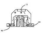
- FIG. 1is a partial fragmented exploded perspective view of a thermo-electric grip of the present invention
- FIG. 2is a top plan view of the thermo-electric grip of the type shown in FIG. 1;
- FIG. 3is a front elevational view of the thermo-electric grip of the type shown in FIG. 1;
- FIG. 4is a side elevational view of the thermo-electric grip of the type shown in FIG. 1;
- FIG. 5is an exploded side elevational view of the thermo-electric grip of the type shown in FIG. 1;
- FIG. 6is a front elevational view of a cooling plate of the thermo-electric grip of the type shown in FIG. 1;
- FIG. 7is a partial sectional side elevational view of the cooling plate of the type shown in FIG. 6;
- FIG. 8is a front elevational view of a sealing plate of the thermo-electric grip of the type shown in FIG. 1;
- FIG. 9is a partial sectional side elevational view of the scaling plate of the type shown in FIG. 8;
- FIG. 10is a front elevational view of a spacer plate of the thermoelectric grip of the type shown in FIG. 1;
- FIG. 11is a partial sectional side elevational view of the spacer plate of the type shown in FIG. 10;
- FIG. 12is a front elevational view of a spacer sub plate of the thermoelectric grip of the type shown in FIG. 1;
- FIG. 13is a partial sectional side elevational view of the spacer sub plate of the type shown in FIG. 12;
- FIG. 14is a partial sectional front elevational view of an alternate embodiment of the thermo-electric grip of the present invention shown coupled to a controller of the thermoelectric cooler;
- FIG. 15is a side elevational view showing a thermo-electric grip of the present invention used to hold tissue in a material testing system.
- FIG. 16is a side elevational view showing a thermoelectric grip of the present invention forming a gripping end of a medical instrument
- FIG. 17is a side elevational view showing a thermoelectric grip of the present invention forming a gripping end of an electro-surgical forceps.
- the present inventionrepresents broadly applicable improvements to grips for holding soft materials including soft tissue.
- the embodiments detailed hereinare intended to be taken as representative or exemplary of those in which the improvements of the invention may be incorporated and are not intended to be limiting.
- the grip 10 of the present inventionwill be described in conjunction with a medical instrument, a material testing system, and an electro-surgical forceps. Those skilled in the art will appreciate that a variety of other devices that utilize grips to hold soft pliable materials or objects may utilize the grips of the present invention.
- the grip of the present inventiondoes not require a cryogenic material, may be controlled and monitored using an electronic temperature controller, and is operable in an environmental chamber and saline bath.
- the grip of the present inventionincludes two spaced apart gripping members, a temperature controller, and a cooling system that cools an outer surface of the gripping members.
- the temperature controlleris used to control the temperature of the outer surface of the gripping members and the cooling system is used to cool the gripping members.
- a thermoelectric cooleris used to cool the outer surface of the gripping members.
- temperature controllers of known suitable constructionmay be used to monitor the temperature of the gripping members and control the voltage to the thermoelectric coolers.
- the rate of cooling the gripping membersmay be controlled by a suitable temperature controller of known suitable construction, to thereby minimize damage to the biological sample caused by freezing it too fast.
- an RTDresistance temperature detector
- the RTDprovides the input temperature for the temperature controlling system.
- An additional RTDis placed between the thermoelectric cooler and a cooling plate to measure the temperature at the hot side of the thermoelectric cooler. The information obtained from the RTD may be used by the temperature controlling system to shut off power to the thermoelectric cooler if the thermoelectric coolers overheat. The temperature controller system will also shut off power to the system if the thermo-electric coolers shut down.
- thermoelectric cooleronly generates freezing temperatures on one side, the side adjacent the outer surface of the gripping members, wherein the grip only freezes the tissue placed between and in contact with the gripping members.
- the temperature of the surrounding saline or mediaremains relatively unchanged by the cooling of the gripping surface of the gripping members.
- the RTDsmay be interfaced with a computer processing unit that controls the power and temperature of the thermo-electric coolers.
- the thermo-electric coolersmay operate continuous at full power, eliminating the need for temperature controllers. An AC to DC converter would still be needed to power the grips.
- a heat sinkcould replace the cold plate on the hot side of the thermo-electric cooler.
- a fanmay be utilized to keep a constant air flowing past the heat sinks to enhance cooling of the hot side of the thermoelectric cooler.
- thermo-electric gripmay be used for gripping soft tissue.
- the grip system 10 of the present inventionis shown mounted to a support 12 of a material testing system.
- the grip system 10 of the preferred embodimentgenerally includes opposed gripping devices 11 .
- Each gripping device 11includes a removable jaw plate 14 , jaw sub-plate 16 , temperature sensor 18 (see FIG. 5 ), thermo-electric cooler 20 , spacer 22 , sealing plate 24 , cooling plate 26 , and temperature sensor 28 (see FIG. 5 ).
- FIG. 5shows further detail of the gripping devices 11 .
- a thermal grease 30 of known suitable constructionis positioned between the removable jaw plate 14 and jaw sub-plate 16 .
- An epoxy 32 of known suitable constructionis used to hold the temperature sensor (RTD) 18 in a groove formed in the jaw sub-plate 16 .
- the spacer 22includes a cavity in which the thermo-electric cooler 20 fits and thermal grease 30 is positioned between the thermal electric cooler 20 and the jaw sub-plate 16 .
- Epoxy 32is used to hold the temperature sensor (RTD) 28 against the thermo-electric cooler 20 .
- Sealant 38seals the cooling plate 26 to the sealing plate 24 and the sealing plate 24 to the spacer 22 .
- Screws 40extend through the cooling plate 26 , sealing plate 24 , spacer 22 , jaw sub-plate 16 , and hold the removable jaw plate 14 against the jaw sub-plate 16 .
- Screws 42fasten together the cooling plate 26 , sealing plate 24 , spacer 22 , and jaw sub-plate 16 , thereby engaging the thermo-electric cooler against the sealing plate 24 and jaw sub-plate 16 .
- FIGS. 2-4shows the assembled grip 10 mounted to support member 12 .
- An actuating member 44typically a rotatable screw device, and alignment pins 46 extend through the support member 12 and the actuating member is attached to gripping devices 11 .
- Rotation of the actuating member 44moves the grip member relative to the support member 12 , allowing the user to change the separation distance between the gripping devices 11 and, consequently, the gripping force on a captured object.
- FIGS. 6-13shows additional details of the jaw sub-plate 16 (see FIGS. 12 - 13 ), spacer 22 (see FIGS. 10 - 11 ), sealing plate 24 (see FIGS. 8 - 9 ), and cooling plate 26 (see FIGS. 6 - 7 ).
- the thermo-electric cooler 20is of the type having a cooling plate 48 aligned adjacent the jaw sub-plate 16 and a hot plate 49 aligned adjacent the sealing plate 24 and cooling plate 26 . In this manner, cooling liquid from a cooling system may be circulated past the hot side 49 of the thermo-electric cooler 20 while containing the cooling liquid within the grip system 10 .
- the jaw plate 14 , jaw sub-plate 16 , sealing plate 24 and cooling plate 26are preferably made from titanium.
- the cooling systemmay consist of a water pump, a water to air heat exchanger, a fan, and a water reservoir (not shown).
- the cooling systempreferably removes a total of 180 watts of heat from the water (90 watts for each grip). It has been determined that for a 1.5 inch square jaw plate, 30 watts of heat needs to be removed from the jaw plate in contact with tissue at 98° F. to maintain the jaw plate 14 at 20° F. To provide 30 watts of cooling power, the thermo-electric coolers typically require about 60 watts of electrical power.
- FIGS. 1-13illustrates a grip 10 having a liquid cooled thermo-electric cooler 20 .
- a heat sinkcould be used to cool the thermoelectric cooler 20 using either natural convection, without a fan, or with forced convection, where a fan is used to force air over the heat sink.
- the heat sinkcould be designed to operate in environmental chamber.
- FIGS. 14 and 15the grip system 10 is shown mounted to the support member 12 of a material testing system 50 .
- FIG. 14shows the grip 10 electrically coupled to a temperature control system 52 and power supply 56 .
- FIG. 15shows the grip 10 electrically coupled to a Computer Processing Unit (CPU) 58 capable of controlling the temperature of the jaw sub-plate 16 , the temperature of the liquid coolant, and the rate of cooling the jaw sub-plate 16 .
- Conduits 54provide a passage for the liquid coolant to the gripping devices 11 .
- FIG. 16shows a medical instrument of known suitable construction in the form of a hand-held scissor arrangement having opposing gripping devices 11 pivotally attached to the end of an elongated rod 72 of a medical instrument 70 .
- the medical instrumentincludes an internal mechanism (not shown) of known suitable construction linked to the handle 74 and each gripping devices 11 to actuate the grip members open and closed.
- Electrical lead 76is electrically coupled to the thermo-electric cooler contained within each gripping device 11 .
- a coolant supply line 78may extend through the elongated rod 72 to the distal end to allow saline to be directed past the cooling plates 26 thereby cooling the hot side of the thermo-electric cooler. Alternatively, the cooling plates may be air cooled.
- FIG. 17shows yet another embodiment of the grip system 10 that takes the form of medical forceps 80 having a pair of opposed tension members 86 and 88 .
- the forcepsare electrically coupled to a power supply 82 and controller 84 .
- the distal end of the forcepsincludes spaced apart gripping devices 11 , wherein the gripping surface of each gripping device is cooled by a thermo-electric cooler 20 contained within each gripping device 11 .
- the grip system 10may be utilized to grip tissue in many of several applications including a material testing system, medical forceps or other medical instrument.
- the useractuates the opposing gripping devices 11 together until the grip members contact the tissue.
- Electrical poweris then supplied to the thermo-electric coolers 20 .
- the temperature control systemmay be utilized to control the amount of power supplied to the thermal-electric coolers 20 .
- the front side or cool side 48(the side closest to the jaw sub-plate 16 ) will fall in temperature and the back side or hot side 49 of the thermo-electric cooler 20 will rise in temperature.
- thermo-electric coolerBecause the front side of the thermo-electric cooler is falling in temperature, heat will be conducted through the thermally conductive grease 30 and jaw sub-plate 16 causing the removable jaw plate 14 to also fall in temperature. When the temperature of the jaw plate 14 falls below 32° F. the test sample freezes.
- cooling plate 26has liquid passages that allow a coolant to be circulated through them. The coolant enters the cooling plate 26 , heats up as it passes over the thermo-electric cooler 20 , and then exits the cold plate 26 to return to the cooling system (described above but not shown).
- temperature sensors 18 and 28sense the temperature of the jaw sub-plate 16 and hot side 49 of the thermo-electric cooler. Signals corresponding to the temperatures sensed by the sensors 18 and 28 are relayed to a CPU or temperature control system 52 .
- the temperature control system 52can independently control the temperature of each gripping device 11 . Based on the temperature reading of the jaw sub-plate 16 , the temperature control system will adjust the power input to the thermo-electric cooler 20 to maintain the jaw sub-plate 16 at a desired temperature.
- the jaw plate 14is configured to enhance the grip on the test sample.
- the configuration on the outer surface of each jaw plate 14may include a series of ridges that will interlock with valleys on the opposite jaw plate.
- the jaw plates 14are removable and the user may substitute one jaw plate having a predefined outer surface configuration with another jaw plate having a different configuration that may enhance the gripping of the soft tissue.
Landscapes
- Health & Medical Sciences (AREA)
- Surgery (AREA)
- Life Sciences & Earth Sciences (AREA)
- Nuclear Medicine, Radiotherapy & Molecular Imaging (AREA)
- Biomedical Technology (AREA)
- Engineering & Computer Science (AREA)
- Otolaryngology (AREA)
- Heart & Thoracic Surgery (AREA)
- Medical Informatics (AREA)
- Molecular Biology (AREA)
- Animal Behavior & Ethology (AREA)
- General Health & Medical Sciences (AREA)
- Public Health (AREA)
- Veterinary Medicine (AREA)
- Sampling And Sample Adjustment (AREA)
Abstract
Description
Claims (24)
Priority Applications (1)
| Application Number | Priority Date | Filing Date | Title |
|---|---|---|---|
| US09/695,497US6547783B1 (en) | 2000-10-24 | 2000-10-24 | Thermo-electric grip for holding soft tissue |
Applications Claiming Priority (1)
| Application Number | Priority Date | Filing Date | Title |
|---|---|---|---|
| US09/695,497US6547783B1 (en) | 2000-10-24 | 2000-10-24 | Thermo-electric grip for holding soft tissue |
Publications (1)
| Publication Number | Publication Date |
|---|---|
| US6547783B1true US6547783B1 (en) | 2003-04-15 |
Family
ID=24793245
Family Applications (1)
| Application Number | Title | Priority Date | Filing Date |
|---|---|---|---|
| US09/695,497Expired - LifetimeUS6547783B1 (en) | 2000-10-24 | 2000-10-24 | Thermo-electric grip for holding soft tissue |
Country Status (1)
| Country | Link |
|---|---|
| US (1) | US6547783B1 (en) |
Cited By (16)
| Publication number | Priority date | Publication date | Assignee | Title |
|---|---|---|---|---|
| US20040101266A1 (en)* | 2002-11-22 | 2004-05-27 | Victor Kardos | Pneumatically actuated bottom mounted device gripper with quick change tooling jaws |
| US20050203505A1 (en)* | 2004-03-15 | 2005-09-15 | Scimed Life Systems, Inc. | Ablation probe with peltier effect thermal control |
| US20100255582A1 (en)* | 2009-04-03 | 2010-10-07 | Porter Blaise D | Deformable transportable bioreactor chamber |
| US20110208174A1 (en)* | 2010-02-23 | 2011-08-25 | Cpsi Biotech | Cryoclamp and method of use |
| US8551088B2 (en) | 2008-03-31 | 2013-10-08 | Applied Medical Resources Corporation | Electrosurgical system |
| USD748259S1 (en) | 2014-12-29 | 2016-01-26 | Applied Medical Resources Corporation | Electrosurgical instrument |
| US9320563B2 (en) | 2010-10-01 | 2016-04-26 | Applied Medical Resources Corporation | Electrosurgical instruments and connections thereto |
| JP2017077492A (en)* | 2010-12-07 | 2017-04-27 | グローブテック 2000 ピーティーワイ リミテッド | Manipulator for surgical clip |
| CN107966361A (en)* | 2017-12-18 | 2018-04-27 | 宋越 | Liquid nitrogen refrigerating type fixture and biological mechanics determining equipment |
| US10149713B2 (en) | 2014-05-16 | 2018-12-11 | Applied Medical Resources Corporation | Electrosurgical system |
| US10231736B2 (en) | 2015-06-11 | 2019-03-19 | The Regents Of The University Of California | System and method for soft tissue gripping |
| US10420603B2 (en) | 2014-12-23 | 2019-09-24 | Applied Medical Resources Corporation | Bipolar electrosurgical sealer and divider |
| US10792092B2 (en) | 2014-05-30 | 2020-10-06 | Applied Medical Resources Corporation | Electrosurgical seal and dissection systems |
| US11696796B2 (en) | 2018-11-16 | 2023-07-11 | Applied Medical Resources Corporation | Electrosurgical system |
| US11843301B2 (en) | 2019-01-22 | 2023-12-12 | Waters Technologies Corporation | Linear motor |
| US11864812B2 (en) | 2018-09-05 | 2024-01-09 | Applied Medical Resources Corporation | Electrosurgical generator control system |
Citations (19)
| Publication number | Priority date | Publication date | Assignee | Title |
|---|---|---|---|---|
| US3369550A (en)* | 1967-02-17 | 1968-02-20 | Thomas A. Armao | Cryogenic clamps |
| US3766910A (en) | 1970-10-09 | 1973-10-23 | P Lake | Disposable delicate tissue retractor |
| US4440167A (en)* | 1980-12-26 | 1984-04-03 | Kabushikikaisha Yoshida | Anesthetizer for dental treatment |
| US4860744A (en) | 1987-11-02 | 1989-08-29 | Raj K. Anand | Thermoelectrically controlled heat medical catheter |
| US5207674A (en) | 1991-05-13 | 1993-05-04 | Hamilton Archie C | Electronic cryogenic surgical probe apparatus and method |
| US5300065A (en) | 1992-11-06 | 1994-04-05 | Proclosure Inc. | Method and apparatus for simultaneously holding and sealing tissue |
| US5458596A (en) | 1994-05-06 | 1995-10-17 | Dorsal Orthopedic Corporation | Method and apparatus for controlled contraction of soft tissue |
| US5674218A (en) | 1990-09-26 | 1997-10-07 | Cryomedical Sciences, Inc. | Cryosurgical instrument and system and method of cryosurgery |
| US5755660A (en) | 1995-10-31 | 1998-05-26 | Tyagi; Narendra S. | Combination surgical retractor, light source, spreader, and suction apparatus |
| US5776130A (en) | 1995-09-19 | 1998-07-07 | Valleylab, Inc. | Vascular tissue sealing pressure control |
| US5873254A (en) | 1996-09-06 | 1999-02-23 | Interface Multigrad Technology | Device and methods for multigradient directional cooling and warming of biological samples |
| US5891142A (en) | 1996-12-06 | 1999-04-06 | Eggers & Associates, Inc. | Electrosurgical forceps |
| US6042539A (en) | 1999-03-26 | 2000-03-28 | Ethicon Endo-Surgery, Inc. | Vacuum-actuated tissue-lifting device and method |
| US6059783A (en) | 1997-06-26 | 2000-05-09 | Kirwan Surgical Products, Inc. | Electro-surgical forceps which minimize or prevent sticking of tissue |
| US6074389A (en) | 1995-03-10 | 2000-06-13 | Seedling Enterprises, Llc | Electrosurgery with cooled electrodes |
| US6091995A (en) | 1996-11-08 | 2000-07-18 | Surx, Inc. | Devices, methods, and systems for shrinking tissues |
| US6096032A (en) | 1996-08-14 | 2000-08-01 | Rowland; Stephen James | Medical cryo-surgical device |
| US6113559A (en) | 1997-12-29 | 2000-09-05 | Klopotek; Peter J. | Method and apparatus for therapeutic treatment of skin with ultrasound |
| US6350262B1 (en)* | 1997-10-22 | 2002-02-26 | Oratec Interventions, Inc. | Method and apparatus for applying thermal energy to tissue asymetrically |
- 2000
- 2000-10-24USUS09/695,497patent/US6547783B1/ennot_activeExpired - Lifetime
Patent Citations (20)
| Publication number | Priority date | Publication date | Assignee | Title |
|---|---|---|---|---|
| US3369550A (en)* | 1967-02-17 | 1968-02-20 | Thomas A. Armao | Cryogenic clamps |
| US3766910A (en) | 1970-10-09 | 1973-10-23 | P Lake | Disposable delicate tissue retractor |
| US4440167A (en)* | 1980-12-26 | 1984-04-03 | Kabushikikaisha Yoshida | Anesthetizer for dental treatment |
| US4860744A (en) | 1987-11-02 | 1989-08-29 | Raj K. Anand | Thermoelectrically controlled heat medical catheter |
| US5674218A (en) | 1990-09-26 | 1997-10-07 | Cryomedical Sciences, Inc. | Cryosurgical instrument and system and method of cryosurgery |
| US5207674A (en) | 1991-05-13 | 1993-05-04 | Hamilton Archie C | Electronic cryogenic surgical probe apparatus and method |
| US5300065A (en) | 1992-11-06 | 1994-04-05 | Proclosure Inc. | Method and apparatus for simultaneously holding and sealing tissue |
| US5458596A (en) | 1994-05-06 | 1995-10-17 | Dorsal Orthopedic Corporation | Method and apparatus for controlled contraction of soft tissue |
| US5569242A (en) | 1994-05-06 | 1996-10-29 | Lax; Ronald G. | Method and apparatus for controlled contraction of soft tissue |
| US6074389A (en) | 1995-03-10 | 2000-06-13 | Seedling Enterprises, Llc | Electrosurgery with cooled electrodes |
| US5776130A (en) | 1995-09-19 | 1998-07-07 | Valleylab, Inc. | Vascular tissue sealing pressure control |
| US5755660A (en) | 1995-10-31 | 1998-05-26 | Tyagi; Narendra S. | Combination surgical retractor, light source, spreader, and suction apparatus |
| US6096032A (en) | 1996-08-14 | 2000-08-01 | Rowland; Stephen James | Medical cryo-surgical device |
| US5873254A (en) | 1996-09-06 | 1999-02-23 | Interface Multigrad Technology | Device and methods for multigradient directional cooling and warming of biological samples |
| US6091995A (en) | 1996-11-08 | 2000-07-18 | Surx, Inc. | Devices, methods, and systems for shrinking tissues |
| US5891142A (en) | 1996-12-06 | 1999-04-06 | Eggers & Associates, Inc. | Electrosurgical forceps |
| US6059783A (en) | 1997-06-26 | 2000-05-09 | Kirwan Surgical Products, Inc. | Electro-surgical forceps which minimize or prevent sticking of tissue |
| US6350262B1 (en)* | 1997-10-22 | 2002-02-26 | Oratec Interventions, Inc. | Method and apparatus for applying thermal energy to tissue asymetrically |
| US6113559A (en) | 1997-12-29 | 2000-09-05 | Klopotek; Peter J. | Method and apparatus for therapeutic treatment of skin with ultrasound |
| US6042539A (en) | 1999-03-26 | 2000-03-28 | Ethicon Endo-Surgery, Inc. | Vacuum-actuated tissue-lifting device and method |
Cited By (38)
| Publication number | Priority date | Publication date | Assignee | Title |
|---|---|---|---|---|
| US20040101266A1 (en)* | 2002-11-22 | 2004-05-27 | Victor Kardos | Pneumatically actuated bottom mounted device gripper with quick change tooling jaws |
| US20050203505A1 (en)* | 2004-03-15 | 2005-09-15 | Scimed Life Systems, Inc. | Ablation probe with peltier effect thermal control |
| US7238184B2 (en)* | 2004-03-15 | 2007-07-03 | Boston Scientific Scimed, Inc. | Ablation probe with peltier effect thermal control |
| US8551088B2 (en) | 2008-03-31 | 2013-10-08 | Applied Medical Resources Corporation | Electrosurgical system |
| US10888371B2 (en) | 2008-03-31 | 2021-01-12 | Applied Medical Resources Corporation | Electrosurgical system |
| US11660136B2 (en) | 2008-03-31 | 2023-05-30 | Applied Medical Resources Corporation | Electrosurgical system |
| US9566108B2 (en) | 2008-03-31 | 2017-02-14 | Applied Medical Resources Corporation | Electrosurgical system |
| US8562598B2 (en) | 2008-03-31 | 2013-10-22 | Applied Medical Resources Corporation | Electrosurgical system |
| US8568411B2 (en) | 2008-03-31 | 2013-10-29 | Applied Medical Resources Corporation | Electrosurgical system |
| US8579894B2 (en) | 2008-03-31 | 2013-11-12 | Applied Medical Resources Corporation | Electrosurgical system |
| US10342604B2 (en) | 2008-03-31 | 2019-07-09 | Applied Medical Resources Corporation | Electrosurgical system |
| US8915910B2 (en) | 2008-03-31 | 2014-12-23 | Applied Medical Resources Corporation | Electrosurgical system |
| US12295642B2 (en) | 2008-03-31 | 2025-05-13 | Applied Medical Resources Corporation | Electrosurgical system |
| US8492135B2 (en) | 2009-04-03 | 2013-07-23 | Tissue Growth Technologies Corporation | Deformable transportable bioreactor chamber |
| US8852933B2 (en) | 2009-04-03 | 2014-10-07 | Illinois Tool Works Inc. | Deformable transportable bioreactor chamber |
| US20100255582A1 (en)* | 2009-04-03 | 2010-10-07 | Porter Blaise D | Deformable transportable bioreactor chamber |
| US20110208174A1 (en)* | 2010-02-23 | 2011-08-25 | Cpsi Biotech | Cryoclamp and method of use |
| US9320563B2 (en) | 2010-10-01 | 2016-04-26 | Applied Medical Resources Corporation | Electrosurgical instruments and connections thereto |
| US12357374B2 (en) | 2010-10-01 | 2025-07-15 | Applied Medical Resources Corporation | Electrosurgical instruments and connections thereto |
| US11864823B2 (en) | 2010-10-01 | 2024-01-09 | Applied Medical Resources Corporation | Electrosurgical instruments and connections thereto |
| US9962222B2 (en) | 2010-10-01 | 2018-05-08 | Applied Medical Resources Corporation | Electrosurgical instruments and connections thereto |
| US10874452B2 (en) | 2010-10-01 | 2020-12-29 | Applied Medical Resources Corporation | Electrosurgical instruments and connections thereto |
| US10064623B2 (en)* | 2010-12-07 | 2018-09-04 | Globetek 2000 Pty Ltd | Surgical clip and clip manipulation device therefor |
| US11246596B2 (en) | 2010-12-07 | 2022-02-15 | Globetek 2000 Pty Ltd | Surgical clip and clip manipulation device therefor |
| JP2017077492A (en)* | 2010-12-07 | 2017-04-27 | グローブテック 2000 ピーティーワイ リミテッド | Manipulator for surgical clip |
| US11672589B2 (en) | 2014-05-16 | 2023-06-13 | Applied Medical Resources Corporation | Electrosurgical system |
| US10149713B2 (en) | 2014-05-16 | 2018-12-11 | Applied Medical Resources Corporation | Electrosurgical system |
| US10792092B2 (en) | 2014-05-30 | 2020-10-06 | Applied Medical Resources Corporation | Electrosurgical seal and dissection systems |
| US12239359B2 (en) | 2014-05-30 | 2025-03-04 | Applied Medical Resources Corporation | Electrosurgical seal and dissection systems |
| US11540871B2 (en) | 2014-12-23 | 2023-01-03 | Applied Medical Resources Corporation | Bipolar electrosurgical sealer and divider |
| US12029472B2 (en) | 2014-12-23 | 2024-07-09 | Applied Medical Resources Corporation | Bipolar electrosurgical sealer and divider |
| US10420603B2 (en) | 2014-12-23 | 2019-09-24 | Applied Medical Resources Corporation | Bipolar electrosurgical sealer and divider |
| USD748259S1 (en) | 2014-12-29 | 2016-01-26 | Applied Medical Resources Corporation | Electrosurgical instrument |
| US10231736B2 (en) | 2015-06-11 | 2019-03-19 | The Regents Of The University Of California | System and method for soft tissue gripping |
| CN107966361A (en)* | 2017-12-18 | 2018-04-27 | 宋越 | Liquid nitrogen refrigerating type fixture and biological mechanics determining equipment |
| US11864812B2 (en) | 2018-09-05 | 2024-01-09 | Applied Medical Resources Corporation | Electrosurgical generator control system |
| US11696796B2 (en) | 2018-11-16 | 2023-07-11 | Applied Medical Resources Corporation | Electrosurgical system |
| US11843301B2 (en) | 2019-01-22 | 2023-12-12 | Waters Technologies Corporation | Linear motor |
Similar Documents
| Publication | Publication Date | Title |
|---|---|---|
| US6547783B1 (en) | Thermo-electric grip for holding soft tissue | |
| EP0840078B1 (en) | Cryoprobe based on a Peltier module | |
| US7244913B2 (en) | Temperature regulator for microchemical chip | |
| US6184504B1 (en) | Temperature control system for electronic devices | |
| US8766656B2 (en) | Systems and methods for thermal control | |
| KR900015686A (en) | Cryogenic surgery devices | |
| US6509553B2 (en) | Method and apparatus for providing an indication of the composition of a fluid particularly useful in heat pumps and vaporizers | |
| US4601587A (en) | Device and method for determining freezing points | |
| CN102187199A (en) | Temperature-controlled rheometer | |
| Kogan et al. | Rayleigh-Bénard convection onset in a compressible fluid: 3 He near T C | |
| US11898977B2 (en) | Temperature control device and temperature control method | |
| CN114441589A (en) | Measuring instrument, method of operating a measuring instrument, and application of a Peltier element | |
| US6007239A (en) | Temperature sensing probe comparator | |
| US6488623B1 (en) | Skin perfusion evaluation apparatus | |
| WO2008047154A2 (en) | Controlled rate freezing | |
| Baudouy | Kapitza resistance and thermal conductivity of Kapton in superfluid helium | |
| EP3242112B1 (en) | Method and device for measurement of liquid flow rate | |
| Njike et al. | Use of Machine Learning Tools to Assess Surface Dryout During Nucleate and Transition Boiling on Surfaces With Different Wetting and Substrate Properties | |
| EP0370073A1 (en) | Apparatus for heating or cooling the body | |
| KR20100028911A (en) | Cooling apparatus having thermistor-embedded thermoelectric module and method of operating the cooling apparatus | |
| GB2188163A (en) | Testing degradation of a sample under thermal cycling | |
| Maruyama et al. | Development of precise-temperature-controlled cooling apparatus for medical application by using peltier effect | |
| CN2672651Y (en) | Hot flow producing device | |
| Han et al. | Effect of thermal properties on heat transfer in cryopreservation and cryosurgery | |
| SU1635098A1 (en) | Device for measuring thermophysical properties |
Legal Events
| Date | Code | Title | Description |
|---|---|---|---|
| AS | Assignment | Owner name:ENDURA TEC SYSTEMS CORP., MINNESOTA Free format text:ASSIGNMENT OF ASSIGNORS INTEREST;ASSIGNORS:VILENDRER, KENT;GRIMES, KELLY;SHUKLA, JAGDEESH;AND OTHERS;REEL/FRAME:011249/0256 Effective date:20001023 | |
| STCF | Information on status: patent grant | Free format text:PATENTED CASE | |
| AS | Assignment | Owner name:BOSE CORPORATION, MASSACHUSETTS Free format text:ASSIGNMENT OF ASSIGNORS INTEREST;ASSIGNOR:ENDURATEC SYSTEMS CORPROATION;REEL/FRAME:015478/0450 Effective date:20040521 | |
| FEPP | Fee payment procedure | Free format text:PAT HOLDER NO LONGER CLAIMS SMALL ENTITY STATUS, ENTITY STATUS SET TO UNDISCOUNTED (ORIGINAL EVENT CODE: STOL); ENTITY STATUS OF PATENT OWNER: LARGE ENTITY | |
| FPAY | Fee payment | Year of fee payment:4 | |
| FPAY | Fee payment | Year of fee payment:8 | |
| FPAY | Fee payment | Year of fee payment:12 | |
| AS | Assignment | Owner name:TA INSTRUMENTS-WATERS L.L.C., MASSACHUSETTS Free format text:ASSIGNMENT OF ASSIGNORS INTEREST;ASSIGNOR:BOSE CORPORATION;REEL/FRAME:035988/0254 Effective date:20150522 |