US6547564B1 - Bone implant having circumferentially oriented roughness - Google Patents
Bone implant having circumferentially oriented roughnessDownload PDFInfo
- Publication number
- US6547564B1 US6547564B1US09/402,918US40291899AUS6547564B1US 6547564 B1US6547564 B1US 6547564B1US 40291899 AUS40291899 AUS 40291899AUS 6547564 B1US6547564 B1US 6547564B1
- Authority
- US
- United States
- Prior art keywords
- axial
- axial section
- peaks
- screw thread
- implant according
- Prior art date
- Legal status (The legal status is an assumption and is not a legal conclusion. Google has not performed a legal analysis and makes no representation as to the accuracy of the status listed.)
- Expired - Lifetime
Links
Images


Classifications
- A—HUMAN NECESSITIES
- A61—MEDICAL OR VETERINARY SCIENCE; HYGIENE
- A61C—DENTISTRY; APPARATUS OR METHODS FOR ORAL OR DENTAL HYGIENE
- A61C8/00—Means to be fixed to the jaw-bone for consolidating natural teeth or for fixing dental prostheses thereon; Dental implants; Implanting tools
- A—HUMAN NECESSITIES
- A61—MEDICAL OR VETERINARY SCIENCE; HYGIENE
- A61B—DIAGNOSIS; SURGERY; IDENTIFICATION
- A61B17/00—Surgical instruments, devices or methods
- A61B17/56—Surgical instruments or methods for treatment of bones or joints; Devices specially adapted therefor
- A61B17/58—Surgical instruments or methods for treatment of bones or joints; Devices specially adapted therefor for osteosynthesis, e.g. bone plates, screws or setting implements
- A61B17/68—Internal fixation devices, including fasteners and spinal fixators, even if a part thereof projects from the skin
- A61B17/84—Fasteners therefor or fasteners being internal fixation devices
- A61B17/86—Pins or screws or threaded wires; nuts therefor
- A61B17/8625—Shanks, i.e. parts contacting bone tissue
- A61B17/863—Shanks, i.e. parts contacting bone tissue with thread interrupted or changing its form along shank, other than constant taper
- A—HUMAN NECESSITIES
- A61—MEDICAL OR VETERINARY SCIENCE; HYGIENE
- A61C—DENTISTRY; APPARATUS OR METHODS FOR ORAL OR DENTAL HYGIENE
- A61C8/00—Means to be fixed to the jaw-bone for consolidating natural teeth or for fixing dental prostheses thereon; Dental implants; Implanting tools
- A61C8/0018—Means to be fixed to the jaw-bone for consolidating natural teeth or for fixing dental prostheses thereon; Dental implants; Implanting tools characterised by the shape
- A61C8/0022—Self-screwing
- A61C8/0025—Self-screwing with multiple threads
Definitions
- the present inventionrelates to an implant having a shaft which is adapted in use to be embedded in bone tissue and which has an outer surface provided with a circumferentially-oriented roughness. This will hereinafter be referred to as an “implant of the type defined”.
- Implants of the type definedare known for use as the anchoring members of dental and orthopaedic prostheses.
- the implantis inserted into a bore-hole drilled into the bone tissue of a bone tissue structure at a site where a prosthesis is required, ordinarily by screwing of the implant into the bore-hole.
- the convention in the artis for the circumferentially-oriented roughness to take the form of a screw thread and in this case the bore-hole will ordinarily be (i) provided with internal threads in advance, or (ii) left untapped with the implant being provided with a self-tapping capacity, e.g. by the provision of one or more axially-extending cutting recesses or notches in the screw thread.
- a superstructure having the prosthetic part of the prosthesisis then secured to the implant.
- the superstructurewill typically consist of a spacer or transmucosal component which engages to the implant to bridge the gingiva overlying the maxilla or mandible at the implant site and the prosthetic part, e.g. a crown, bridge or denture, is then secured to the spacer.
- the prosthetic parte.g. a crown, bridge or denture
- the superstructurecan take as is known in the art.
- the prosthetic partmay be secured directly to the implant.
- the long-term integrity of the prosthesisis highly dependent on the successful osseointegration of the implant with the bone tissue structure, that is to say, the remodelling of the bone tissue in the bone tissue structure into direct apposition with the implant.
- a study on the factors which affect the osseointegration of implantswas undertaken by Professor Per-Ingvar Br ⁇ dot over (a) ⁇ nemark and co-workers and the results were published in a book entitled “ Osseointegrated Implants in the Treatment of the Edentulous law: Experience from a 10- Year Period”, Almqvist & Wiskell International. Sweden , 1977.
- Implants of the type definedare not necessarily always used as part of a prosthesis, in some instances they can be a “stand alone” structure. As an example, implants of the type defined are known for use as bone fixation screws. The success of these “stand alone” implants is also highly dependent on their successful osseointegration.
- Implants of the type definedhave some notable advantages in promoting successful osseointegration with the adjacent bone tissue, a major one being as a result of the fact that the main loads on the implant in the clinical situation are axial loads. These implants are very well suited to support axial loads and this may be particularly important in the initial stages of the osseointegration process in which it is important that the implant is fully stable and as immovable as possible in the bore-hole (primary fixation). One can consider this to be due to the bone tissue growing into the troughs between adjacent peaks of the circumferentially-oriented roughness on the implant.
- the Applicanthas also identified that it is advantageous for an implant of the type defined to transmit the axial loading thereon evenly to the adjacent bone tissue to prevent high stress concentrations occurring in the adjacent bone tissue and concomitantly marginal bone tissue resorption. If marginal bone tissue resorption occurs this will reduce the anchorage of the implant and may undermine the long term stability of the implant resulting in due course in failure of the prosthesis. In the particular case of dental prostheses, the aesthetic appeal is also undermined by marginal bone tissue resorption, an important drawback since dental prosthetics forms part of the field of cosmetic surgery.
- the present inventionproposes to provide an implant of the type defined having features which promote its maintenance in a bone tissue structure whilst at the same time facilitating its insertion into the bone tissue structure in the first place.
- an implant of the type defined in which the circumferentially-oriented roughnesshas first and second axial sections each comprising a series of circumferentially-oriented peaks which have a crest and which are axially spaced apart by troughs, the axial spacing between the crests of adjacent peaks in the first axial section is less than the axial spacing between the crests of adjacent peaks in the second axial section and the first and second axial sections of circumferentially-oriented roughness are adapted in use to provide the same or substantially the same pitch.
- the larger inter-peak spacing in the second axial section of circumferentially-oriented roughnessacts to promote primary fixation of the implant in the bone tissue during the early phases of osseointegration since each trough between adjacent peaks can capture a relatively large volume of bone tissue to interlock the implant with the bone tissue.
- the smaller inter-peak spacing in the first axial sectionenables the stiffness of the implant to be increased thereby improving the ability of the implant to transmit loads more evenly to the bone tissue to inhibit marginal bone resorption.
- Adapting the first and second axial sections to have the same or substantially the same pitchmeans that both axial sections produce the same or substantially the same axial displacement into the bone tissue on one rotation thereof thus ensuring that the provision of the two different axial sections of circumferentially-oriented roughness does not complicate insertion of the implant into the bone tissue. If the first and second axial sections of circumferentially-oriented roughness did not have the same or substantially the same pitch then a greater force would need to be applied to insert the implant resulting in fractures being formed in the bone tissue.
- the pitchis a predetermined distance
- the ratio of the predetermined distance to the axial spacing between the crests of adjacent peaks in the first axial sectionis a first multiple integer
- the ratio of the predetermined distance to the axial spacing between the crests of adjacent peaks in the second axial sectionis a second multiple integer which is less than the first multiple integer.
- the first multiple integermay be a multiple integer of the second multiple integer.
- the peaks in the first and second axial sectionsare circumferentially-oriented at a common inclined angle to the main axis of the implant.
- the shafthas a coronal end and an apical end and the first axial section is located coronally of the second axial section.
- the first and second axial sectionsare contiguous.
- the first axial sectionextends from the coronal end of the shaft to a position coronally of the apical end and the second axial section extends from the first axial section towards the apical end of the shaft.
- the implantmay have a coronal end which is spaced coronally from the coronal end of the shaft by a smooth coronal portion of the implant, as in the embodiment of the invention hereinafter to be described, in which case the smooth coronal portion is preferably no more than 4% of the total length of the implant, more preferably in the range 1.5-3.7% of said total length.
- the axial extent of the first axial sectionis greater than the axial extent of the second axial section.
- the axial extent of the first axial sectionmay be less than the axial extent of the second axial section or the axial extents of the first and second axial sections may be the same or substantially the same.
- a blind boreextends apically into the shaft from the coronal end thereof to an end surface in-between the apical and coronal ends of the shaft for a superstructure to be secured to the implant, the blind bore comprising an internally-threaded section having a coronal edge and an apical edge for screw connection of the superstructure to the implant with the apical edge terminating at a position which is disposed apically of the first axial section.
- the apical edge of the internally-threaded section of the blind boremay terminate at a position which is disposed coronally of the second axial section.
- the internally-threaded sectionmay be an apical section of the blind bore, as in the embodiment of the invention hereinafter to be described.
- all or substantially all of the crests of the peaks in the first and second axial sectionslie on an axial plane parallel to the main axis of the shaft. Expressed another way, the major transverse dimension of the implant at the first and second axial sections is uniform.
- the height of the peaks, as measured from the troughs to the crests, in the first axial sectiondiffers from that in the second axial section.
- the height of the peaks in the first axial sectionis less than that in the second axial section. This feature further enables the stiffness of the implant to be increased.
- the height of the peaks, as measured from the troughs to the crests, in the first axial sectionis the same or substantially the same as in the second axial section.
- the ratio of the height of the peaks, as measured from the troughs to the crests, to the axial spacing between the crests of adjacent peaks in the first axial sectionis the same or substantially the same as in the second axial section.
- the height of the peaks, as measured from the troughs to the crests, in the first axial sectionis no greater than 0.2 mm, for example in the range 0.02-0.20 mm, and the height of the peaks, as measured from the troughs to the crests, in the second axial section is greater than that in the first axial section, for instance in the range 0.15 mm to 1 mm.
- Such heightscomplement the primary fixation and stiffness characteristics of the implant provided by the different inter-peak spacings of the first and second axial sections.
- the peaks in the first and second axial sectionsare bounded by flank surfaces and the angle between the opposed flanks of adjacent peaks in the first and second axial sections is the same.
- the troughs in at least one of the first and second axial sectionsare a continuous curved surface.
- the circumferentially-oriented roughness in the first and/or second axial sectionis presented by a screw thread profile with the circumferentially-oriented peaks being defined by thread elements of the screw thread profile.
- the screw thread profile of the first and/or second axial sectionwill be formed by a screw thread structure.
- the screw thread structure of the first axial sectionmay be formed by a first set of independent screw threads each having turns; the turns of each independent screw thread in the first set defining thread elements in the first axial section and being sequentially arranged with the turns of the other independent screw threads in the first set with adjacent turns of one of the independent screw threads of the first set being axially-spaced apart by a predetermined spacing distance which is the same for adjacent turns of the other independent screw threads in the first set; and the screw thread structure of the second axial section may be formed by (i) an independent screw thread having turns which define the thread elements of the second axial section and are axially-spaced apart by the predetermined spacing distance or essentially the predetermined spacing distance, or (ii) a second set of independent screw threads numbering less than in the first set each having turns, the turns of each independent screw thread in the second set defining thread elements in the second axial section and
- one or more of the independent screw threads of the first and second axial sectionsare shared by the first and second axial sections.
- the or each independent screw thread of at least one of the first and second axial sectionsis a microthread, that is to say, a thread having a height which is no greater than 0.2 mm.
- only the screw threads of the first axial sectionare microthreads. It could be the case, though, that the screw threads of both the first and second axial sections are microthreads.
- the circumferentially-oriented roughness in at least one of the first and second axial sectionsis formed by a series of axially spaced-apart cirucmferential lines of beads.
- the beads in each linemay be circumferentially spaced-apart.
- the implantis a dental implant adapted for implantation in the maxilla or mandible of an edentulous patient for supporting a superstructure which presents one or more artificial teeth.
- a method of implanting an implant into a bone tissue structurecomprising the steps of providing an implant according to the invention, providing a bore-hole in the bone tissue structure and screwing the implant into the bore-hole so that the shaft is embedded in the bone tissue.
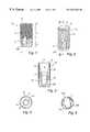
- FIG. 1is a side view of the dental implant
- FIG. 2is a perspective view of the dental implant
- FIG. 3is a cross-sectional side view of the dental implant
- FIG. 4is a plan view of the dental implant
- FIG. 5is an underneath view of the dental implant
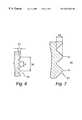
- FIG. 6is an exploded view of a first section of the external screw threading on the dental implant.
- FIG. 7is an exploded view of a second section of the external screw threading on the dental implant.
- FIG. 8is a perspective view of a dental implant having circumferentially-oriented roughness consisting of axially spaced, cirucmferential lines of beads.
- FIG. 9is a perspective view of a dental implant having circumferentially-oriented roughness in which the height of the peaks in the first axial section and the height of the peaks in the second axial section is the same.
- FIG. 10In the accompanying Figures of drawings there is shown various views of a self tapping endosseous screw-type dental implant 10 of a dental prosthesis in accordance with the present invention.
- the implant 10is for insertion into a bore-hole drilled into a toothless-site in a maxilla or mandible of a partially or fully edentulous patient to anchor to the maxilla or mandible a superstructure of the prosthesis which comprises a prosthetic part, namely one or more artificial teeth.
- the implant 10is made from commercially pure titanium, a titanium alloy, another biocompatible metal or metal alloy or a ceramic to promote osseointegration of the implant with the bone tissue of the boundary walls of the bore-hole.
- the implant 10has an apical end 1 which is presented by a first conical section 3 to ease insertion of the implant 10 into the bore-hole, a coronal end 5 presented by a second conical section 6 and an intermediate section 7 of constant diameter which extends between the first and second conical sections 3 , 6 .
- the length of the implantmay be in the range 8-19 mm, depending on the clinical situation, and have a maximum outer diameter of 3.5 mm or 4.0 mm.
- the axial extent of the second conical portion 6is preferably small compared to the total length of the implant 10 , as an example no more than 4.0% perhaps in the range 1.5%-3.7%.
- a socket 9 having an open end 11 in the coronal end 5extends apically into the implant 10 .
- the socket 9is for receiving an abutment structure (not shown) which will bridge the gingiva overlying the bore-hole and support/present the prosthetic part.
- the socket 9consists of a conical coronal section 13 , an internally-threaded apical section 15 and a cylindrical intermediate section 17 .
- the abutment structurewill have an apical section which is able to be screw retained in the implant socket 9 for releasably securing the abutment structure to the implant 10 . As shown in FIGS.
- the outer surface of the implant 10 over the major part of its lengthis provided with screw threading which is divided into coronal and apical sections 19 , 21 having different thread heights h 1 , h 2 .
- the coronal section 19 of screw threadingis positioned on the intermediate cylindrical section 7 of the implant 10 whereas the apical section 21 of the screw threading bridges the intermediate cylindrical section 7 and the first conical section 3 .
- the screw threading in the coronal section 19is composed of a series of axially spaced-apart screw thread elements each having the same height h 1 .
- These screw thread elementsare formed by the turns of three separate microthreads (triple microthread) which are sequentially arranged. This means that a screw thread element formed by a first turn of one of the microthreads is axially spaced from a screw thread element formed by the next turn of that microthread by two other screw thread elements, each being respectively formed by a turn of the other two microthreads.
- a screw thread element belonging to one of the microthreadsis therefore axially spaced from the next adjacent screw thread element formed by the same microthread by screw thread elements from each of the other two microthreads.
- microthreadis meant a screw thread having a height which is no greater than 0.2 mm. Accordingly, the screw thread elements in the coronal section 19 have a height h 1 which is no greater than 0.2 mm, preferably 0.1 mm.
- the screw threading in the apical section 21is composed of a series of axially spaced-apart screw thread elements which, other than those in the first conical section 3 , each have the same height h 2 .
- the screw thread elements of the apical section 21are formed by the turns of a single macrothread.
- macrothreadis meant a screw thread having a height greater than 0.2 mm. Accordingly, the screw thread elements of the apical section 21 on the intermediate section 7 have a height greater than 0.2 mm, preferably 0.3 mm.
- the angle formed between the coronal and apical flanks of adjacent screw thread elementsis the same in both the coronal and apical sections 19 , 21 .
- Preferably the angle formedis 80°.
- FIGS. 6 and 7that the coronal and apical flanks of adjacent screw thread elements in the coronal and apical sections 19 , 21 are connected by a curved surface, that is to say, there is no axial straight part in-between adjacent screw thread elements in the coronal and apical sections 19 , 21 .
- the tips of the screw thread elements of the coronal section 19 and the tips of the screw thread elements of the apical section 21 positioned in the intermediate cylindrical section 7 of the implant 10all lie on a common plane when viewed in side section and circumscribe the circumference of the cylindrical intermediate section 7 .
- the major diameter of the intermediate cylindrical section 7is constant.
- the crest-to-crest spacing between adjacent screw thread elements in the coronal section 19is different from the crest-to-crest spacing between adjacent screw thread elements in the apical section 21 .
- the crest-to-crest spacing in the coronal section 19is d whereas the crest-to-crest spacing in the apical section 21 is 3 d .
- dmay be 0.22 mm.
- the crest-to-crest spacing between adjacent screw thread elements of each microthreadis the same as that between adjacent screw thread elements of the macrothread, namely 3 d .
- the fact that the crest-to-crest spacing between adjacent screw thread elements per se in the coronal section 19 is less than that in the apical section 21is, of course, due to adjacent turns of each microthread being interspersed with a turn from each of the other two microthreads.
- the turns of the microthreads and the macrothreadsare aligned parallel with one another at an inclined angle to the rotational axis of the implant 10 .
- the pitch of the coronal and apical threaded sections, 19 , 21will be the same, again being 3 d .
- the pitch of the implant 10remains uniform along its length notwithstanding the difference in crest-to-crest spacing in the apical and coronal threaded sections 19 , 21 , that is to say, the coronal and apical screw threaded sections 19 , 21 will both produce the same axial displacement of the implant 10 when being screwed into the bore-hole provided therefor at the toothless site in the maxilla or mandible. If the coronal and apical sections 19 , 21 did not have constant pitch then a greater force would need to be applied to insert the implant 10 into the bore-hole resulting in bone threads formed in the boundary wall of the bore-hole being fractured.
- the first threaded sectionis formed by the sequential arrangement of the turns of a first set of screw threads each having the same pitch and the second threaded section is formed by (i) a single screw thread having the same pitch as the screw threads in the first threaded section, or (ii) the sequential arrangement of the turns of a second set of screw threads numbering less than in the first set each having the same pitch as the screw threads in the first threaded section.
- the number of screw threads in the first threaded sectiondoes not need to be a multiple integer of the number of screw threads in the second threaded section, as in the illustrated embodiment of the invention. For example, there could be five microthreads in the coronal section 19 and two macrothreads in the apical section 21 .
- the implant 10has three cutting recesses or grooves 23 a , 23 b , 23 c positioned symmetrically about the circumference of the apical end 1 of the implant 10 for self-tapping of the implant 10 when being screwed into the bore-hole provided therefor in the maxilla or mandible.
- the implant 10is screwed into the bore-hole provided at the toothless-site in the maxilla or mandible such that the coronal and apical sections 19 , 21 are embedded in bone tissue with the second conical section 6 protruding from the maxilla or mandible.
- the screw thread elements of the macrothreads in the apical section 21 of the implant 10act to provide primary fixation of the implant in the bore-hole.
- the screw thread elements of the microthreads in the coronal section 19also act to provide fixation for the implant 10 in the bore-hole.
- the implant 10is stiffer than it would be if the screw threads were macrothreads as in the apical section 21 . This enables the implant 10 to transfer loads more evenly to the bone tissue adjacent the implant 10 and consequently promote better remodelling of the bone tissue into apposition with the implant 10 .
- the microthreadsare positioned at the coronal end 5 of the implant 10 the loads transferred thereby helps alleviate the problem of bone tissue resorption at the coronal surface of the maxilla or mandible (marginal bone tissue resorption).
- microthreads in the coronal section 19also enables a reasonable wall thickness to be retained around the tapered coronal section 13 of the socket 9 in the implant 10 , when compared to the wall thickness that would result from use of macrothreads in the coronal section 19 in any event. This helps preserve the mechanical strength of the implant 10 .
- the dental implant 10has a screw threaded outer surface 19 , 21 which (i) makes it straightforward for the implant 10 to be screwed into a bone tissue structure, and (ii) promotes the short- and long-term stability of the implant 10 in the bone tissue structure.
Landscapes
- Health & Medical Sciences (AREA)
- Orthopedic Medicine & Surgery (AREA)
- Life Sciences & Earth Sciences (AREA)
- Animal Behavior & Ethology (AREA)
- General Health & Medical Sciences (AREA)
- Public Health (AREA)
- Veterinary Medicine (AREA)
- Oral & Maxillofacial Surgery (AREA)
- Dentistry (AREA)
- Epidemiology (AREA)
- Surgery (AREA)
- Molecular Biology (AREA)
- Neurology (AREA)
- Engineering & Computer Science (AREA)
- Biomedical Technology (AREA)
- Heart & Thoracic Surgery (AREA)
- Medical Informatics (AREA)
- Nuclear Medicine, Radiotherapy & Molecular Imaging (AREA)
- Dental Prosthetics (AREA)
- Prostheses (AREA)
- Crystals, And After-Treatments Of Crystals (AREA)
- Shafts, Cranks, Connecting Bars, And Related Bearings (AREA)
- Materials For Medical Uses (AREA)
- Dental Preparations (AREA)
Abstract
Description
The present invention relates to an implant having a shaft which is adapted in use to be embedded in bone tissue and which has an outer surface provided with a circumferentially-oriented roughness. This will hereinafter be referred to as an “implant of the type defined”.
Implants of the type defined are known for use as the anchoring members of dental and orthopaedic prostheses. To this end, the implant is inserted into a bore-hole drilled into the bone tissue of a bone tissue structure at a site where a prosthesis is required, ordinarily by screwing of the implant into the bore-hole. The convention in the art is for the circumferentially-oriented roughness to take the form of a screw thread and in this case the bore-hole will ordinarily be (i) provided with internal threads in advance, or (ii) left untapped with the implant being provided with a self-tapping capacity, e.g. by the provision of one or more axially-extending cutting recesses or notches in the screw thread.
A superstructure having the prosthetic part of the prosthesis is then secured to the implant. In the case of a dental prosthesis, the superstructure will typically consist of a spacer or transmucosal component which engages to the implant to bridge the gingiva overlying the maxilla or mandible at the implant site and the prosthetic part, e.g. a crown, bridge or denture, is then secured to the spacer. There are various other forms that the superstructure can take as is known in the art. For instance, the prosthetic part may be secured directly to the implant.
The long-term integrity of the prosthesis is highly dependent on the successful osseointegration of the implant with the bone tissue structure, that is to say, the remodelling of the bone tissue in the bone tissue structure into direct apposition with the implant. A study on the factors which affect the osseointegration of implants was undertaken by Professor Per-Ingvar Br{dot over (a)}nemark and co-workers and the results were published in a book entitled “Osseointegrated Implants in the Treatment of the Edentulous law: Experience from a10-Year Period”, Almqvist & Wiskell International. Stockholm, Sweden, 1977. It was found by Br{dot over (a)}nemark et al that successful osseointegration depends upon inter alia the use of biocompatible materials for the implant, for example titanium and alloys thereof, and the surgical procedure adopted, for example leaving the implant unloaded for several months before adding the superstructure. Implants of the type defined are not necessarily always used as part of a prosthesis, in some instances they can be a “stand alone” structure. As an example, implants of the type defined are known for use as bone fixation screws. The success of these “stand alone” implants is also highly dependent on their successful osseointegration.
Implants of the type defined have some notable advantages in promoting successful osseointegration with the adjacent bone tissue, a major one being as a result of the fact that the main loads on the implant in the clinical situation are axial loads. These implants are very well suited to support axial loads and this may be particularly important in the initial stages of the osseointegration process in which it is important that the implant is fully stable and as immovable as possible in the bore-hole (primary fixation). One can consider this to be due to the bone tissue growing into the troughs between adjacent peaks of the circumferentially-oriented roughness on the implant.
The Applicant has also identified that it is advantageous for an implant of the type defined to transmit the axial loading thereon evenly to the adjacent bone tissue to prevent high stress concentrations occurring in the adjacent bone tissue and concomitantly marginal bone tissue resorption. If marginal bone tissue resorption occurs this will reduce the anchorage of the implant and may undermine the long term stability of the implant resulting in due course in failure of the prosthesis. In the particular case of dental prostheses, the aesthetic appeal is also undermined by marginal bone tissue resorption, an important drawback since dental prosthetics forms part of the field of cosmetic surgery.
The present invention proposes to provide an implant of the type defined having features which promote its maintenance in a bone tissue structure whilst at the same time facilitating its insertion into the bone tissue structure in the first place.
According to the present invention there is provided an implant of the type defined in which the circumferentially-oriented roughness has first and second axial sections each comprising a series of circumferentially-oriented peaks which have a crest and which are axially spaced apart by troughs, the axial spacing between the crests of adjacent peaks in the first axial section is less than the axial spacing between the crests of adjacent peaks in the second axial section and the first and second axial sections of circumferentially-oriented roughness are adapted in use to provide the same or substantially the same pitch.
The larger inter-peak spacing in the second axial section of circumferentially-oriented roughness acts to promote primary fixation of the implant in the bone tissue during the early phases of osseointegration since each trough between adjacent peaks can capture a relatively large volume of bone tissue to interlock the implant with the bone tissue. The smaller inter-peak spacing in the first axial section, on the other hand, enables the stiffness of the implant to be increased thereby improving the ability of the implant to transmit loads more evenly to the bone tissue to inhibit marginal bone resorption. Adapting the first and second axial sections to have the same or substantially the same pitch means that both axial sections produce the same or substantially the same axial displacement into the bone tissue on one rotation thereof thus ensuring that the provision of the two different axial sections of circumferentially-oriented roughness does not complicate insertion of the implant into the bone tissue. If the first and second axial sections of circumferentially-oriented roughness did not have the same or substantially the same pitch then a greater force would need to be applied to insert the implant resulting in fractures being formed in the bone tissue.
In an embodiment of the invention such as the one hereinafter to be described the pitch is a predetermined distance, the ratio of the predetermined distance to the axial spacing between the crests of adjacent peaks in the first axial section is a first multiple integer and the ratio of the predetermined distance to the axial spacing between the crests of adjacent peaks in the second axial section is a second multiple integer which is less than the first multiple integer. The first multiple integer may be a multiple integer of the second multiple integer.
In an embodiment of the invention such as the one hereinafter to be described the peaks in the first and second axial sections are circumferentially-oriented at a common inclined angle to the main axis of the implant.
In an embodiment of the invention such as the one hereinafter to be described the shaft has a coronal end and an apical end and the first axial section is located coronally of the second axial section.
In an embodiment of the invention such as the one hereinafter to be described the first and second axial sections are contiguous.
In an embodiment of the invention such as the one hereinafter to be described the first axial section extends from the coronal end of the shaft to a position coronally of the apical end and the second axial section extends from the first axial section towards the apical end of the shaft. The implant may have a coronal end which is spaced coronally from the coronal end of the shaft by a smooth coronal portion of the implant, as in the embodiment of the invention hereinafter to be described, in which case the smooth coronal portion is preferably no more than 4% of the total length of the implant, more preferably in the range 1.5-3.7% of said total length.
In an embodiment of the invention such as the one hereinafter to be described the axial extent of the first axial section is greater than the axial extent of the second axial section. Alternatively, the axial extent of the first axial section may be less than the axial extent of the second axial section or the axial extents of the first and second axial sections may be the same or substantially the same.
In an embodiment of the invention in which the first axial section is disposed coronally of the second axial section, such as the one hereinafter to be described, a blind bore extends apically into the shaft from the coronal end thereof to an end surface in-between the apical and coronal ends of the shaft for a superstructure to be secured to the implant, the blind bore comprising an internally-threaded section having a coronal edge and an apical edge for screw connection of the superstructure to the implant with the apical edge terminating at a position which is disposed apically of the first axial section. Alternately, the apical edge of the internally-threaded section of the blind bore may terminate at a position which is disposed coronally of the second axial section. The internally-threaded section may be an apical section of the blind bore, as in the embodiment of the invention hereinafter to be described.
In an embodiment of the invention such as the one hereinafter to be described all or substantially all of the crests of the peaks in the first and second axial sections lie on an axial plane parallel to the main axis of the shaft. Expressed another way, the major transverse dimension of the implant at the first and second axial sections is uniform.
In an embodiment of the invention such as the one hereinafter to be described the height of the peaks, as measured from the troughs to the crests, in the first axial section differs from that in the second axial section. To advantage, the height of the peaks in the first axial section is less than that in the second axial section. This feature further enables the stiffness of the implant to be increased.
In an alternative embodiment of the invention the height of the peaks, as measured from the troughs to the crests, in the first axial section is the same or substantially the same as in the second axial section.
In an embodiment of the invention such as the one hereinafter to be described the ratio of the height of the peaks, as measured from the troughs to the crests, to the axial spacing between the crests of adjacent peaks in the first axial section is the same or substantially the same as in the second axial section.
In an embodiment of the invention such as the one hereinafter to be described the height of the peaks, as measured from the troughs to the crests, in the first axial section is no greater than 0.2 mm, for example in the range 0.02-0.20 mm, and the height of the peaks, as measured from the troughs to the crests, in the second axial section is greater than that in the first axial section, for instance in the range 0.15 mm to 1 mm. Such heights complement the primary fixation and stiffness characteristics of the implant provided by the different inter-peak spacings of the first and second axial sections.
In an embodiment of the invention such as the one hereinafter to be described the peaks in the first and second axial sections are bounded by flank surfaces and the angle between the opposed flanks of adjacent peaks in the first and second axial sections is the same.
In an embodiment of the invention such as the one hereinafter to be described the troughs in at least one of the first and second axial sections are a continuous curved surface.
In an embodiment of the invention such as the one hereinafter to be described the circumferentially-oriented roughness in the first and/or second axial section is presented by a screw thread profile with the circumferentially-oriented peaks being defined by thread elements of the screw thread profile.
Typically, the screw thread profile of the first and/or second axial section will be formed by a screw thread structure. In such case, the screw thread structure of the first axial section may be formed by a first set of independent screw threads each having turns; the turns of each independent screw thread in the first set defining thread elements in the first axial section and being sequentially arranged with the turns of the other independent screw threads in the first set with adjacent turns of one of the independent screw threads of the first set being axially-spaced apart by a predetermined spacing distance which is the same for adjacent turns of the other independent screw threads in the first set; and the screw thread structure of the second axial section may be formed by (i) an independent screw thread having turns which define the thread elements of the second axial section and are axially-spaced apart by the predetermined spacing distance or essentially the predetermined spacing distance, or (ii) a second set of independent screw threads numbering less than in the first set each having turns, the turns of each independent screw thread in the second set defining thread elements in the second axial section and being sequentially arranged with the turns of the other independent screw threads in the second set with adjacent turns of each independent screw thread of the second set being axially-spaced apart by the predetermined spacing distance or essentially the predetermined spacing distance.
In an embodiment of the invention one or more of the independent screw threads of the first and second axial sections are shared by the first and second axial sections.
In an embodiment of the invention such as the one hereinafter to be described the or each independent screw thread of at least one of the first and second axial sections is a microthread, that is to say, a thread having a height which is no greater than 0.2 mm.
In an embodiment of the invention only the screw threads of the first axial section are microthreads. It could be the case, though, that the screw threads of both the first and second axial sections are microthreads.
In an embodiment of the invention the circumferentially-oriented roughness in at least one of the first and second axial sections is formed by a series of axially spaced-apart cirucmferential lines of beads. The beads in each line may be circumferentially spaced-apart.
In an embodiment of the invention such as the one hereinafter to be described the implant is a dental implant adapted for implantation in the maxilla or mandible of an edentulous patient for supporting a superstructure which presents one or more artificial teeth.
According to the invention there is further provided a method of implanting an implant into a bone tissue structure comprising the steps of providing an implant according to the invention, providing a bore-hole in the bone tissue structure and screwing the implant into the bore-hole so that the shaft is embedded in the bone tissue.
By way of example, a self-tapping endosseous screw-type dental implant in accordance with the present invention will now be described with reference to the accompanying Figures of drawings in which:
FIG. 1 is a side view of the dental implant;
FIG. 2 is a perspective view of the dental implant;
FIG. 3 is a cross-sectional side view of the dental implant;
FIG. 4 is a plan view of the dental implant;
FIG. 5 is an underneath view of the dental implant;
FIG. 6 is an exploded view of a first section of the external screw threading on the dental implant; and
FIG. 7 is an exploded view of a second section of the external screw threading on the dental implant.
FIG. 8 is a perspective view of a dental implant having circumferentially-oriented roughness consisting of axially spaced, cirucmferential lines of beads.
FIG. 9 is a perspective view of a dental implant having circumferentially-oriented roughness in which the height of the peaks in the first axial section and the height of the peaks in the second axial section is the same.
In the accompanying Figures of drawings there is shown various views of a self tapping endosseous screw-typedental implant 10 of a dental prosthesis in accordance with the present invention. Theimplant 10 is for insertion into a bore-hole drilled into a toothless-site in a maxilla or mandible of a partially or fully edentulous patient to anchor to the maxilla or mandible a superstructure of the prosthesis which comprises a prosthetic part, namely one or more artificial teeth. Theimplant 10 is made from commercially pure titanium, a titanium alloy, another biocompatible metal or metal alloy or a ceramic to promote osseointegration of the implant with the bone tissue of the boundary walls of the bore-hole.
Referring to FIG. 1, theimplant 10 has anapical end 1 which is presented by a firstconical section 3 to ease insertion of theimplant 10 into the bore-hole, acoronal end 5 presented by a secondconical section 6 and anintermediate section 7 of constant diameter which extends between the first and secondconical sections
The length of the implant may be in the range 8-19 mm, depending on the clinical situation, and have a maximum outer diameter of 3.5 mm or 4.0 mm. The axial extent of the secondconical portion 6 is preferably small compared to the total length of theimplant 10, as an example no more than 4.0% perhaps in the range 1.5%-3.7%.
Turning to FIGS. 2 to4, asocket 9 having anopen end 11 in thecoronal end 5 extends apically into theimplant 10. Thesocket 9 is for receiving an abutment structure (not shown) which will bridge the gingiva overlying the bore-hole and support/present the prosthetic part. Thesocket 9 consists of a conicalcoronal section 13, an internally-threadedapical section 15 and a cylindricalintermediate section 17. The abutment structure will have an apical section which is able to be screw retained in theimplant socket 9 for releasably securing the abutment structure to theimplant 10. As shown in FIGS. 1 to3,6 and7, the outer surface of theimplant 10 over the major part of its length is provided with screw threading which is divided into coronal andapical sections coronal section 19 of screw threading is positioned on the intermediatecylindrical section 7 of theimplant 10 whereas theapical section 21 of the screw threading bridges the intermediatecylindrical section 7 and the firstconical section 3.
Referring to FIG. 6, the screw threading in thecoronal section 19 is composed of a series of axially spaced-apart screw thread elements each having the same height h1. These screw thread elements are formed by the turns of three separate microthreads (triple microthread) which are sequentially arranged. This means that a screw thread element formed by a first turn of one of the microthreads is axially spaced from a screw thread element formed by the next turn of that microthread by two other screw thread elements, each being respectively formed by a turn of the other two microthreads. A screw thread element belonging to one of the microthreads is therefore axially spaced from the next adjacent screw thread element formed by the same microthread by screw thread elements from each of the other two microthreads. By “microthread” is meant a screw thread having a height which is no greater than 0.2 mm. Accordingly, the screw thread elements in thecoronal section 19 have a height h1 which is no greater than 0.2 mm, preferably 0.1 mm.
Referring to FIG. 7, the screw threading in theapical section 21 is composed of a series of axially spaced-apart screw thread elements which, other than those in the firstconical section 3, each have the same height h2. The screw thread elements of theapical section 21 are formed by the turns of a single macrothread. By “macrothread” is meant a screw thread having a height greater than 0.2 mm. Accordingly, the screw thread elements of theapical section 21 on theintermediate section 7 have a height greater than 0.2 mm, preferably 0.3 mm.
The angle formed between the coronal and apical flanks of adjacent screw thread elements is the same in both the coronal andapical sections apical sections apical sections
As can be seen particularly from FIGS. 1 and 3, the tips of the screw thread elements of thecoronal section 19 and the tips of the screw thread elements of theapical section 21 positioned in the intermediatecylindrical section 7 of theimplant 10 all lie on a common plane when viewed in side section and circumscribe the circumference of the cylindricalintermediate section 7. In other words, the major diameter of the intermediatecylindrical section 7 is constant.
As shown in FIGS. 6 and 7, as well as the screw thread elements in the coronal andapical sections coronal section 19 is different from the crest-to-crest spacing between adjacent screw thread elements in theapical section 21. The crest-to-crest spacing in thecoronal section 19 is d whereas the crest-to-crest spacing in theapical section 21 is3d. As an example, d may be 0.22 mm. In the case where h1 is 0.1 mm and h2 is 0.3 mm the ratio of the inter-crest spacing to the height would thus be the same for both the coronal and apical threadedsections
It follows from the above that the crest-to-crest spacing between adjacent screw thread elements of each microthread is the same as that between adjacent screw thread elements of the macrothread, namely3d. The fact that the crest-to-crest spacing between adjacent screw thread elements per se in thecoronal section 19 is less than that in theapical section 21 is, of course, due to adjacent turns of each microthread being interspersed with a turn from each of the other two microthreads. It will also be noted from FIG. 1 that the turns of the microthreads and the macrothreads are aligned parallel with one another at an inclined angle to the rotational axis of theimplant 10.
It will be gathered from the above that the pitch of the coronal and apical threaded sections,19,21 will be the same, again being3d. For this reason, the pitch of theimplant 10 remains uniform along its length notwithstanding the difference in crest-to-crest spacing in the apical and coronal threadedsections sections implant 10 when being screwed into the bore-hole provided therefor at the toothless site in the maxilla or mandible. If the coronal andapical sections implant 10 into the bore-hole resulting in bone threads formed in the boundary wall of the bore-hole being fractured.
As a rule, a constant pitch for two threaded sections having different crest-to-crest spacings between the adjacent screw thread elements thereof will result where the first threaded section is formed by the sequential arrangement of the turns of a first set of screw threads each having the same pitch and the second threaded section is formed by (i) a single screw thread having the same pitch as the screw threads in the first threaded section, or (ii) the sequential arrangement of the turns of a second set of screw threads numbering less than in the first set each having the same pitch as the screw threads in the first threaded section. The number of screw threads in the first threaded section does not need to be a multiple integer of the number of screw threads in the second threaded section, as in the illustrated embodiment of the invention. For example, there could be five microthreads in thecoronal section 19 and two macrothreads in theapical section 21.
As shown in FIGS. 1 to3 and5, theimplant 10 has three cutting recesses orgrooves apical end 1 of theimplant 10 for self-tapping of theimplant 10 when being screwed into the bore-hole provided therefor in the maxilla or mandible. In use, theimplant 10 is screwed into the bore-hole provided at the toothless-site in the maxilla or mandible such that the coronal andapical sections conical section 6 protruding from the maxilla or mandible. The screw thread elements of the macrothreads in theapical section 21 of theimplant 10 act to provide primary fixation of the implant in the bore-hole. The screw thread elements of the microthreads in thecoronal section 19 also act to provide fixation for theimplant 10 in the bore-hole. As a result of the screw threads in thecoronal section 19 being microthreads, though, theimplant 10 is stiffer than it would be if the screw threads were macrothreads as in theapical section 21. This enables theimplant 10 to transfer loads more evenly to the bone tissue adjacent theimplant 10 and consequently promote better remodelling of the bone tissue into apposition with theimplant 10. Moreover, as the microthreads are positioned at thecoronal end 5 of theimplant 10 the loads transferred thereby helps alleviate the problem of bone tissue resorption at the coronal surface of the maxilla or mandible (marginal bone tissue resorption).
The provision of microthreads in thecoronal section 19 also enables a reasonable wall thickness to be retained around the taperedcoronal section 13 of thesocket 9 in theimplant 10, when compared to the wall thickness that would result from use of macrothreads in thecoronal section 19 in any event. This helps preserve the mechanical strength of theimplant 10.
To conclude, thedental implant 10 has a screw threadedouter surface implant 10 to be screwed into a bone tissue structure, and (ii) promotes the short- and long-term stability of theimplant 10 in the bone tissue structure.
It will be appreciated that the invention has been illustrated with reference to an exemplary embodiment and that the invention can be varied in many different ways within the scope of the appended claims. As an example, although the illustrated example is a dental implant the invention has equal application in other areas, for example, the orthopaedic area.
Finally, it is to be noted that the inclusion in the appended claims of reference numerals used in the figures of drawings is purely for illustrative purposes and not to be construed as having a limiting effect on the scope of the claims.
Claims (82)
1. A dental implant comprising a shaft having a coronal end, an apical end, and an outer surface provided with a circumferentially-oriented roughness having a first axial section and a second axial section,
wherein the implant is sized and configured to be implanted in a maxilla or mandible of a human patient,
wherein the first axial section is located coronally of the second axial section and the sections of circumferentially-oriented roughness have the same or substantially the same pitch,
wherein each of the sections comprises a series of circumferentially-oriented peaks, each peak having a crest and being axially spaced apart from adjacent peaks by troughs,
wherein the axial spacing between the crests of adjacent peaks in the first axial section is less than the axial spacing between the crests of adjacent peaks in the second axial section,
wherein the crests of all of the peaks or substantially all of the peaks in the first and second axial sections lie on an axial plane parallel to the main axis of the shaft and
wherein a bore comprising an internally-threaded section extends apically into the shaft from the coronal end.
2. The implant according toclaim 1 , wherein the first and second axial sections are contiguous.
3. The implant according toclaim 2 , wherein the first axial section extends from the coronal end of the shaft to a position coronally of the apical end and the second axial section extends from the first axial section towards the apical end.
4. The implant according to any one of claims1,2 and3 wherein the bore extends to an end surface in-between the apical and coronal ends of the shaft, wherein the structure of the end-surface is sized and configured to be secured to a superstructure, wherein the internally-threaded section has a coronal edge and an apical edge for screw connection of the superstructure to the implant, and wherein the apical edge of the internally-threaded section of the bore terminates at a position which is disposed apically of the first axial section.
5. The implant according toclaim 4 wherein the internally-threaded section is an apical section of the blind-bore.
6. The implant according toclaim 1 , wherein the pitch is a predetermined distance and the ratio of the predetermined distance to the axial spacing between the crests of adjacent peaks in the first axial section is a first multiple integer, the ratio of the predetermined distance to the axial spacing between the crests of adjacent peaks in the second axial section is a second multiple integer and the first multiple integer is greater than the second multiple integer.
7. The implant according toclaim 1 or6 , wherein the height of the peaks, as measured from the troughs to the crests, in the first axial section differs from that in the second axial section.
8. The implant according toclaim 7 , wherein the height of the peaks in the first axial section is less than the height of the peaks in the second axial section.
9. The implant according toclaim 1 or6 , wherein the height of the peaks, as measured from the troughs to the crests, in the first axial section is the same or substantially the same as in the second axial section.
10. The implant according toclaim 1 or6 , wherein the ratio of the height of the peaks, as measured from the troughs to the crests, to the axial spacing between the crests of adjacent peaks in the first axial section is the same or substantially the same as in the second axial section.
11. The implant according toclaim 1 or6 , wherein the height of the peaks, as measured from the troughs to the crests, in the first axial section is no greater than 0.20 mm.
12. The implant according toclaim 1 or6 , wherein the height of the peaks, as measured from the troughs to the crests, in the second axial section is in the range 0.15-1 mm.
13. The implant according toclaim 1 or6 , wherein the circumferentially-oriented roughness in at least one of the first and second axial sections is presented by a screw thread profile with the circumferentially-oriented peaks being defined by thread elements of the screw thread profile.
14. The implant according toclaim 13 , wherein the screw thread profile is formed by a screw thread structure.
15. The implant according toclaim 13 wherein both the first and second axial sections are presented by a screw thread profile with the circumferentially-oriented peaks being defined by thread elements of the screw thread profiles.
16. The implant according toclaim 15 , wherein the screw thread profile of the first axial section is formed by a first set of at least two independent screw threads each screw thread forming turns, the turns of each independent screw thread in the first set defining thread elements in the first axial section and being alternately arranged with the screw thread elements of the other independent screw threads in the first set, wherein adjacent screw thread elements of any of the independent screw threads of the first set are axially spaced apart from each other by a predetermined spacing distance, wherein the spacing distance is the same for the adjacent screw thread elements of the other independent screw threads in the first set, and wherein,
the screw thread profile of the second axial section is formed by (i) a single screw thread having turns which define the thread elements of the second axial section and are axially spaced apart from each other by the predetermined spacing distance or approximately the predetermined spacing distance, or (ii) a second set of independent screw threads numbering less than in the first set, each screw thread having turns, the turns of each independent screw thread in the second set defining screw thread elements in the second axial section, the screw thread elements of one independent screw thread of the second set being alternately arranged with the screw thread elements of the other independent screw threads in the second set with adjacent screw thread elements of each independent screw thread of the second set being axially spaced apart from each other by the predetermined spacing distance or approximately the predetermined spacing distance.
17. The implant according toclaim 16 , wherein at least one of the independent screw threads of the first and second axial sections is shared by the first and second axial sections.
18. The implant according toclaim 16 , wherein the or each independent screw thread of at least one of the first and second axial sections is a microthread.
19. The implant according toclaim 18 , wherein only the independent screw threads of the first axial section are microthreads.
20. The implant according toclaim 18 , wherein the independent screw threads of the first and second axial sections are microthreads.
21. The implant according toclaim 1 or6 , wherein the circumferentially-oriented roughness in at least one of the first and second axial sections is formed by a series of axially spaced apart circumferential lines of beads.
22. The implant according toclaim 21 , wherein the beads in each line are circumferentially spaced apart.
23. The implant according toclaim 1 , wherein the height (h1, h2) of the peaks, as measured from the troughs to the crests, in the first axial section differs from that in the second axial section.
24. The implant according toclaim 1 , wherein the height (h1, h2) of the peaks, as measured from the troughs to the crests, in the first axial section is the same or substantially the same as in the second axial section.
25. The implant according toclaim 1 , wherein the ratio of the height of the peaks, as measured from the troughs to the crests, to the axial spacing between the crests of adjacent peaks in the first axial section is the same or substantially the same as in the second axial section.
26. The implant according toclaim 1 , wherein the circumferentially-oriented roughness consists of a first axial section and a second axial section.
27. An implant comprising a shaft, wherein the shaft is sized and configured to be embedded in bone tissue and comprises a coronal end having a coronal end portion with a maximum lateral dimension not exceeding the maximum lateral dimension of the shaft, an apical end, and an outer surface having at least two axial sections having circumferentially-oriented roughness, each of the sections comprising a series of circumferentially-oriented peaks, each peak having a crest and being axially spaced apart from adjacent peaks by troughs,
wherein the axial spacing between the crests of adjacent peaks of a section is less than the axial spacing between the crests of adjacent peaks of any apically-located axial section,
wherein the sections of circumferentially-oriented roughness have the same or substantially the same pitch, and
wherein the crests of all of the peaks or substantially all of the peaks in the first and second axial sections lie on an axial plane parallel to the main axis of the shaft.
28. The implant according toclaim 27 , wherein at least two of the axial sections are contiguous.
29. The implant according toclaim 27 , wherein a blind bore extends apically into the shaft from the coronal end to an end surface in-between the apical and coronal ends of the shaft, wherein the structure of the end-surface is capable of being secured to a superstructure, wherein the blind bore comprises an internally-threaded section having a coronal edge and an apical edge for screw connection of the superstructure to the implant, and wherein the apical edge of the internally-threaded section of the blind bore terminates at a position which is disposed apically of the first axial section of the at least two axial sections.
30. The implant according toclaim 27 , wherein for at least one pair of the axial sections, a first axial section being located coronally of a second axial section, the pitch is a predetermined distance, that the ratio of the predetermined distance to the axial spacing between the crests of adjacent peaks in the first axial section is a first multiple integer, that the ratio of the predetermined distance to the axial spacing between the crests of adjacent peaks in the second axial section is a second multiple integer and that the first multiple integer is greater than the second multiple integer.
31. The implant according toclaim 30 , the height of the peaks, as measured from the troughs to the crests, in the first axial section differs from that in the second axial section.
32. The implant according toclaim 31 , wherein the height of the peaks in the first axial section is less than the height of the peaks in the second axial section.
33. The implant according toclaim 30 , wherein the height of the peaks, as measured from the troughs to the crests, in the first axial section is the same or substantially the same as in the second axial section.
34. The implant according toclaim 30 , wherein the ratio of the height of the peaks, as measured from the troughs to the crests, to the axial spacing between the crests of adjacent peaks in the first axial section is the same or substantially the same as in the second axial section.
35. The implant according toclaim 30 , wherein the height of the peaks, as measured from the troughs to the crests, in the first axial section is no greater than 0.20 mm.
36. The implant according toclaim 30 , wherein the height of the peaks, as measured from the troughs to the crests, in the second axial section is in the range 0.15-1 mm.
37. The implant according toclaim 30 , wherein the circumferentially-oriented roughness in at least one of the first and second axial sections is presented by a screw thread profile with the circumferentially-oriented peaks being defined by thread elements of the screw thread profile.
38. The implant according toclaim 37 , wherein both the first and second axial sections are presented by a screw thread profile wherein the circumferentially-oriented peaks are defined by screw thread elements of the screw thread profiles, wherein the screw thread profile of the first axial section is formed by a first set of at least two independent screw threads, each screw thread having turns, the turns of each independent screw thread in the first set defining thread elements in the first axial section and being alternately arranged with the screw thread elements of the other independent screw threads in the first set, wherein adjacent screw thread elements of each one of the independent screw threads of the first set are axially spaced apart from each other by a predetermined spacing distance, wherein the spacing distance is the same for the adjacent screw thread elements of the other independent screw threads in the first set, and wherein,
the screw thread profile of the second axial section is formed by (i) a single screw thread having turns which define the screw thread elements of the second axial section and are axially spaced apart from each other by the predetermined spacing distance or approximately the predetermined spacing distance, or (ii) a second set of independent screw threads numbering less than in the first set, each having turns, the turns of each independent screw thread in the second set defining screw thread elements in the second axial section, the screw thread elements of one independent screw thread of the second set being alternately arranged with the screw thread elements of the other independent screw threads of the second set with adjacent screw thread elements of each independent screw thread of the second set being axially spaced apart from each other by the predetermined spacing distance or approximately the predetermined spacing distance.
39. The implant according toclaim 27 , wherein the implant is sized and configured to be implanted in a maxilla or a mandible of an edentulous patient for supporting a superstructure which presents one or more artificial teeth.
40. An implant comprising a shaft, wherein the shaft is sized and configured to be embedded in bone tissue and comprises a coronal end having a coronal end portion with a maximum lateral dimension not exceeding the maximum lateral dimension of the shaft an apical end, and an outer surface provided with a circumferentially-oriented roughness consisting of a first axial section and a second axial section, each of the sections comprising a series of circumferentially-oriented peaks, each peak having a crest and being axially spaced apart from adjacent peaks by troughs,
wherein the axial spacing between the crests of adjacent peaks in the first axial section is less than the axial spacing between the crests of adjacent peaks in the second axial section,
wherein the first and second axial sections of circumferentially-oriented roughness have the same or substantially the same pitch,
wherein the first axial section is located coronally of the second axial section, and
wherein the crests of all of the peaks or substantially all of the peaks in the first and second axial sections lie on an axial plane parallel to the main axis of the shaft.
41. The implant according toclaim 40 , wherein the first and second axial sections are contiguous.
42. The implant according toclaim 40 , wherein a blind bore extends apically into the shaft from the coronal end to an end surface in-between the apical and coronal ends of the shaft, wherein the structure of the end-surface is capable of being secured to a superstructure, wherein the blind bore comprises an internally-threaded section having a coronal edge and an apical edge for screw connection of the superstructure to the implant, and wherein the apical edge of the internally-threaded section of the blind bore terminates at a position which is disposed apically of the first axial section.
43. The implant according toclaim 40 , wherein the pitch is a predetermined distance, that the ratio of the predetermined distance to the axial spacing between the crests of adjacent peaks in the first axial section is a first multiple integer, that the ratio of the predetermined distance to the axial spacing between the crests of adjacent peaks in the second axial section is a second multiple integer and that the first multiple integer is greater than the second multiple integer.
44. The implant according toclaim 40 or43 , wherein the height of the peaks, as measured from the troughs to the crests, in the first axial section differs from that in the second axial section.
45. The implant according toclaim 44 , wherein the height of the peaks in the first axial section is less than the height of the peaks in the second axial section.
46. The implant according toclaim 40 or43 , wherein the height of the peaks, as measured from the troughs to the crests, in the first axial section is the same or substantially the same as in the second axial section.
47. The implant according toclaim 40 or43 , wherein the ratio of the height of the peaks, as measured from the troughs to the crests, to the axial spacing between the crests of adjacent peaks in the first axial section is the same or substantially the same as in the second axial section.
48. The implant according toclaim 40 or43 , wherein the height of the peaks, as measured from the troughs to the crests, in the first axial section is no greater than0.20 mm.
49. The implant according toclaim 40 or43 , wherein the height of the peaks, as measured from the troughs to the crests, in the second axial section is in the range 0.15-1 mm.
50. The implant according toclaim 40 or43 , wherein the circumferentially-oriented roughness in at least one of the first and second axial sections is presented by a screw thread profile with the circumferentially-oriented peaks being defined by thread elements of the screw thread profile.
51. The implant according toclaim 50 , wherein both the first and second axial sections are presented by a screw thread profile wherein the circumferentially-oriented peaks are defined by screw thread elements of the screw thread profiles, wherein the screw thread profile of the first axial section is formed by a first set of at least two independent screw threads each screw thread forming turns, the turns of each independent screw thread in the first set defining screw thread elements in the first axial section and being alternately arranged with the screw thread elements of the other independent screw threads in the first set, wherein adjacent screw thread elements of each of the independent screw threads of the first set are axially spaced apart from each other by a predetermined spacing distance, wherein the spacing distance is the same for the adjacent screw thread elements of the other independent screw threads in the first set, and wherein,
the screw thread profile of the second axial section is formed by (i) a single screw thread having turns which define the thread elements of the second axial section and are axially spaced apart from each other by the predetermined spacing distance or approximately the predetermined spacing distance, or (ii) a second set of independent screw threads numbering less than in the first set, each screw thread forming turns, the turns of each independent screw thread in the second set defining screw thread elements in the second axial section and being alternately arranged with the screw thread elements of the other independent screw threads in the second set, with adjacent screw thread elements of each independent screw thread of the second set being axially spaced apart from each other by the predetermined spacing distance or approximately the predetermined spacing distance.
52. The implant according toclaim 40 , the implant is sized and configured to be implanted in a maxilla or a mandible of an edentulous patient for supporting a superstructure which presents one or more artificial teeth.
53. An implant comprising a shaft sized and configured to be embedded in a maxilla or mandible, wherein the shaft comprises a coronal end, an apical end, and an outer surface having a plurality of axial sections having circumferentially-oriented roughness and the sections of circumferentially-oriented roughness have the same or substantially the same pitch, each of the sections comprising a series of circumferentially-oriented peaks, each peak having a crest and being axially spaced apart from adjacent peaks by troughs,
wherein the axial spacing between the crests of adjacent peaks of a section is less than the axial spacing between the crests of adjacent peaks of the adjacent apically-located axial section,
wherein the crests of all of the peaks or substantially all of the peaks in at least two of said sections lie on an axial plane parallel to the main axis of the shaft, and
wherein a bore comprising an internally-threaded section extends apically into the shaft from the coronal end.
54. The implant according toclaim 53 , wherein the crests of all of the peaks, or substantially all of the peaks, in all of said axial sections lie on an axial plane parallel to the main axis of the shaft.
55. The implant according toclaim 54 , wherein the height (h1, h2) of the peaks, as measured from the troughs to the crests, in the first axial section differs from that in the second axial section.
56. The implant according toclaim 54 , wherein the height (h1, h2) of the peaks, as measured from the troughs to the crests, in the first axial section is the same or substantially the same as in the second axial section.
57. The implant according toclaim 54 , wherein the ratio of the height of the peaks, as measured from the troughs to the crests, to the axial spacing between the crests of adjacent peaks in the first axial section is the same or substantially the same as in the second axial section.
58. A dental implant comprising a shaft having a coronal end, an apical end, and an outer surface provided with a circumferentially-oriented roughness having a first axial section and a second axial section,
wherein the implant is sized and configured to be implanted in a maxilla or mandible of a human patient,
wherein the first axial section is located coronally of the second axial section and the sections of circumferentially-oriented roughness have the same or substantially the same pitch,
wherein each of the sections comprises a series of circumferentially-oriented peaks, each peak having a crest and being axially spaced apart from adjacent peaks by troughs, and wherein the axial spacing between the crests of adjacent peaks in the first axial section is less than the axial spacing between the crests of adjacent peaks in the second axial section,
wherein the crests of all of the peaks or substantially all of the peaks in the first and second axial sections lie in an axial plane parallel to the main axis of the shaft, and
wherein a bore extends apically into the shaft from the coronal end and terminates at a position disposed apically from the first axial section.
59. The implant according toclaim 58 , wherein the first and second axial sections are contiguous.
60. The implant according toclaim 59 , wherein the first axial section extends from the coronal end of the shaft to a position coronally of the apical end and the second axial section extends from the first axial section towards the apical end.
61. The implant according to any one ofclaim 58 -60, wherein the bore extends to an end surface in-between the apical and coronal ends of the shaft, wherein the structure of the end-surface is capable of being secured to a superstructure, wherein the bore comprises an internally-threaded section having a coronal edge and an apical edge for screw connection of the superstructure to the implant, and wherein the apical edge of the internally-threaded section of the bore terminates at a position which is disposed apically of the first axial section.
62. The implant according toclaim 61 , wherein the internally-threaded section is an apical section of the bore.
63. The implant according to claim 94, wherein the pitch is a predetermined distance and the ratio of the predetermined distance to the axial spacing between the crests of adjacent peaks in the first axial section is a first multiple integer, the ratio of the predetermined distance to the axial spacing between the crests of adjacent peaks in the second axial section is a second multiple integer and the first multiple integer is greater than the second multiple integer.
64. The implant according toclaim 58 -63, wherein the height of the peaks, as measured from the troughs to the crests, in the first axial section differs from that in the second axial section.
65. The implant according toclaim 64 , wherein the height of the peaks in the first axial section is less than the height of the peaks in the second axial section.
66. The implant according toclaim 58 or63 the height of the peaks, as measured from the troughs to the crests, in the first axial section is the same or substantially the same as in the second axial section.
67. The implant according toclaim 58 or63 , wherein the ratio of the height.of the peaks, as measured from the troughs to the crests, to the axial spacing between the crests of adjacent peaks in the first axial section is the same or substantially the same as in the second axial section.
68. The implant according toclaim 58 or63 , wherein the height of the peaks, as measured from the troughs to the crests, in the first axial section is no greater than 0.20 mm.
69. The implant according toclaim 58 or63 , wherein the height of the peaks, as measured from the troughs to the crests, in the second axial section is in the range 0.15-1 mm.
70. The implant according toclaim 58 or63 , wherein the circumferentially-oriented roughness in at least one of the first and second axial sections is presented by a screw thread profile with the circumferentially-oriented peaks being defined by thread elements of the screw thread profile.
71. The implant according toclaim 70 wherein both the first and second axial sections are presented by a screw thread profile with the circumferentially-oriented peaks being defined by thread elements of the screw thread profiles.
72. The implant according toclaim 70 , wherein the or each screw thread profile is formed by a screw thread structure.
73. The implant according toclaim 71 , wherein the or each screw thread profile is formed by a screw thread structure.
74. The implant according toclaim 73 , wherein the screw thread profile of the first axial section is formed by a first set of independent screw threads each screw thread having turns, the turns of each independent screw thread in the first set defining thread elements in the first axial section and being sequentially arranged with the turns of the other independent screw threads in the first set with adjacent turns of one of the independent screw threads of the first set being axially spaced apart by a predetermined spacing distance which is the same for adjacent turns of the other independent screw threads in the first set, and wherein the screw thread structure of the second axial section is formed by (i) an independent screw thread having turns which define the thread elements of the second axial section and are axially spaced apart by the predetermined spacing distance or essentially the predetermined spacing distance, or (ii) a second set of independent screw threads numbering less than in the first set each having turns, the turns of each independent screw thread in the second set defining thread elements in the second axial section and being sequentially arranged with the turns of the other independent screw threads in the second set with adjacent turns of each independent screw thread of the second set being axially spaced apart by the predetermined spacing distance or a distance approximating the predetermined spacing distance.
75. The implant according toclaim 74 , wherein at least one of the independent screw threads of the first and second axial sections is shared by the first and second axial sections.
76. The implant according toclaim 74 , wherein the or each independent screw thread of at least one of the first and second axial sections is a microthread.
77. The implant according toclaim 76 , wherein only the independent screw threads of the first axial section are microthreads.
78. The implant according toclaim 76 , wherein the independent screw threads of the first and second axial sections are microthreads.
79. The implant according toclaim 58 or63 , wherein the circumferentially-oriented roughness in at least one of the first and second axial sections is formed by a series of axially spaced apart circumferential lines of beads.
80. The implant according toclaim 79 , wherein the beads in each line are circumferentially spaced apart.
81. The implant according toclaim 58 , wherein the circumferentially-oriented roughness consists of a first axial section and a second axial section.
82. A method of implanting an implant into a bone structure comprising the steps of:
providing an implant according to any one of claims1,6,27,40,53, and58:
providing a bore-hole in the bone tissue structure; and
screwing the implant into the bore-hole so that the shaft is embedded in the bone tissue.
Priority Applications (8)
| Application Number | Priority Date | Filing Date | Title |
|---|---|---|---|
| US10/361,383US7264470B2 (en) | 1998-07-17 | 2003-02-10 | Implant having circumferentially oriented roughness |
| US11/828,402US7517218B2 (en) | 1998-07-17 | 2007-07-26 | Implant having circumferentially oriented roughness |
| US11/828,472US7959440B2 (en) | 1998-07-17 | 2007-07-26 | Implant having circumferentially oriented roughness |
| US11/828,501US20080020347A1 (en) | 1998-07-17 | 2007-07-26 | Implant |
| US11/828,449US7883336B2 (en) | 1998-07-17 | 2007-07-26 | Implant having circumferentially oriented roughness |
| US11/828,423US20080020344A1 (en) | 1998-07-17 | 2007-07-26 | Implant |
| US11/828,523US8277219B2 (en) | 1998-07-17 | 2007-07-26 | Implant having circumferentially oriented roughness |
| US13/102,461US8333590B2 (en) | 1998-07-17 | 2011-05-06 | Implant having circumferentially oriented roughness |
Applications Claiming Priority (3)
| Application Number | Priority Date | Filing Date | Title |
|---|---|---|---|
| SE9802571ASE9802571D0 (en) | 1998-07-17 | 1998-07-17 | Implant |
| SE9802571 | 1998-07-17 | ||
| PCT/SE1999/001272WO2000003657A1 (en) | 1998-07-17 | 1999-07-14 | Implant |
Related Parent Applications (1)
| Application Number | Title | Priority Date | Filing Date |
|---|---|---|---|
| PCT/SE1999/001272A-371-Of-InternationalWO2000003657A1 (en) | 1998-07-17 | 1999-07-14 | Implant |
Related Child Applications (1)
| Application Number | Title | Priority Date | Filing Date |
|---|---|---|---|
| US10/361,383ContinuationUS7264470B2 (en) | 1998-07-17 | 2003-02-10 | Implant having circumferentially oriented roughness |
Publications (1)
| Publication Number | Publication Date |
|---|---|
| US6547564B1true US6547564B1 (en) | 2003-04-15 |
Family
ID=20412114
Family Applications (9)
| Application Number | Title | Priority Date | Filing Date |
|---|---|---|---|
| US09/402,918Expired - LifetimeUS6547564B1 (en) | 1998-07-17 | 1999-07-14 | Bone implant having circumferentially oriented roughness |
| US10/361,383Expired - LifetimeUS7264470B2 (en) | 1998-07-17 | 2003-02-10 | Implant having circumferentially oriented roughness |
| US11/828,449Expired - Fee RelatedUS7883336B2 (en) | 1998-07-17 | 2007-07-26 | Implant having circumferentially oriented roughness |
| US11/828,423AbandonedUS20080020344A1 (en) | 1998-07-17 | 2007-07-26 | Implant |
| US11/828,472Expired - Fee RelatedUS7959440B2 (en) | 1998-07-17 | 2007-07-26 | Implant having circumferentially oriented roughness |
| US11/828,402Expired - Fee RelatedUS7517218B2 (en) | 1998-07-17 | 2007-07-26 | Implant having circumferentially oriented roughness |
| US11/828,501AbandonedUS20080020347A1 (en) | 1998-07-17 | 2007-07-26 | Implant |
| US11/828,523Expired - Fee RelatedUS8277219B2 (en) | 1998-07-17 | 2007-07-26 | Implant having circumferentially oriented roughness |
| US13/102,461Expired - Fee RelatedUS8333590B2 (en) | 1998-07-17 | 2011-05-06 | Implant having circumferentially oriented roughness |
Family Applications After (8)
| Application Number | Title | Priority Date | Filing Date |
|---|---|---|---|
| US10/361,383Expired - LifetimeUS7264470B2 (en) | 1998-07-17 | 2003-02-10 | Implant having circumferentially oriented roughness |
| US11/828,449Expired - Fee RelatedUS7883336B2 (en) | 1998-07-17 | 2007-07-26 | Implant having circumferentially oriented roughness |
| US11/828,423AbandonedUS20080020344A1 (en) | 1998-07-17 | 2007-07-26 | Implant |
| US11/828,472Expired - Fee RelatedUS7959440B2 (en) | 1998-07-17 | 2007-07-26 | Implant having circumferentially oriented roughness |
| US11/828,402Expired - Fee RelatedUS7517218B2 (en) | 1998-07-17 | 2007-07-26 | Implant having circumferentially oriented roughness |
| US11/828,501AbandonedUS20080020347A1 (en) | 1998-07-17 | 2007-07-26 | Implant |
| US11/828,523Expired - Fee RelatedUS8277219B2 (en) | 1998-07-17 | 2007-07-26 | Implant having circumferentially oriented roughness |
| US13/102,461Expired - Fee RelatedUS8333590B2 (en) | 1998-07-17 | 2011-05-06 | Implant having circumferentially oriented roughness |
Country Status (15)
| Country | Link |
|---|---|
| US (9) | US6547564B1 (en) |
| EP (4) | EP2314252A3 (en) |
| JP (1) | JP4278305B2 (en) |
| KR (2) | KR20010071941A (en) |
| CN (2) | CN1200653C (en) |
| AT (2) | ATE347328T1 (en) |
| AU (1) | AU745694B2 (en) |
| BR (1) | BR9912155B1 (en) |
| CA (1) | CA2336251C (en) |
| DE (2) | DE69934314T2 (en) |
| ES (2) | ES2317441T3 (en) |
| IL (2) | IL140489A0 (en) |
| RU (1) | RU2231992C2 (en) |
| SE (1) | SE9802571D0 (en) |
| WO (1) | WO2000003657A1 (en) |
Cited By (121)
| Publication number | Priority date | Publication date | Assignee | Title |
|---|---|---|---|---|
| US20030120279A1 (en)* | 1998-07-17 | 2003-06-26 | Stig Hansson | Implant having circumferentially oriented roughness |
| US20040006346A1 (en)* | 2001-08-15 | 2004-01-08 | Anders Holmen | Implant, arrangement comprising an implant, and method for inserting said implant in bone tissue |
| US20040142304A1 (en)* | 2001-12-03 | 2004-07-22 | Richard Cottrell | Modified dental implant fixture |
| US20040219488A1 (en)* | 2000-12-09 | 2004-11-04 | Young-Wook Choi | Dental implant and head for a compacttion drill |
| US20050033427A1 (en)* | 2003-06-13 | 2005-02-10 | Freilich Martin Allen | Structural/biological implant system |
| US20050147943A1 (en)* | 2004-01-06 | 2005-07-07 | Sang-Kohn Chang | Dental implant fixture |
| US20060084035A1 (en)* | 2003-04-25 | 2006-04-20 | Volzirkon Gmbh & Co. Kg | Dental implant |
| US20060172258A1 (en)* | 2005-02-01 | 2006-08-03 | Niznick Gerald A | Tapered endosseous dental implants with external multiple lead threads |
| US20060204930A1 (en)* | 2003-03-26 | 2006-09-14 | Young-Taek Sul | Helical implant |
| US20060286509A1 (en)* | 2005-06-17 | 2006-12-21 | Zimmer Dental, Inc. | Dental restorative system and components |
| US20060286508A1 (en)* | 2005-06-17 | 2006-12-21 | Zimmer Dental, Inc. | Dental restorative system and components |
| WO2007107995A1 (en)* | 2006-03-21 | 2007-09-27 | Uri Arni | Dental implant |
| US20070269766A1 (en)* | 2003-12-11 | 2007-11-22 | Jan Hall | Implant |
| US20070298379A1 (en)* | 2005-10-20 | 2007-12-27 | D Alise David D | Screw-type dental implant |
| USD565181S1 (en)* | 2005-12-27 | 2008-03-25 | Bti, I+D, S.L. | Dental implant |
| WO2008053058A1 (en)* | 2006-10-30 | 2008-05-08 | Antonio Coso Echevarria | Dental implant, wrench and system for removing the implant from the container thereof, transferring said implant and inserting same directly in the patient's mouth using the wrench |
| US20080233539A1 (en)* | 2005-08-22 | 2008-09-25 | Hans-Dieter Rossler | Abutment For a Tooth Implant |
| US20080241792A1 (en)* | 2005-08-22 | 2008-10-02 | Hans-Dieter Rossler | Tooth Implant |
| USD588699S1 (en) | 2005-12-27 | 2009-03-17 | Bti, I+D, S.L. | Dental implant |
| WO2009054650A1 (en)* | 2007-10-22 | 2009-04-30 | Osstemimplant Co., Ltd. | Dental fixture |
| US20090130631A1 (en)* | 2006-11-30 | 2009-05-21 | Chun-Leon Chen | Implant root for tooth implanting |
| WO2009072764A1 (en)* | 2007-12-06 | 2009-06-11 | Osstemimplant Co., Ltd. | Dental implant |
| US20090240289A1 (en)* | 2005-11-27 | 2009-09-24 | Holger Zipprich | Orthodontic Anchoring Screw |
| US7601165B2 (en) | 2006-09-29 | 2009-10-13 | Biomet Sports Medicine, Llc | Method and apparatus for forming a self-locking adjustable suture loop |
| US7608098B1 (en) | 2004-11-09 | 2009-10-27 | Biomet Sports Medicine, Llc | Bone fixation device |
| US7608092B1 (en) | 2004-02-20 | 2009-10-27 | Biomet Sports Medicince, LLC | Method and apparatus for performing meniscus repair |
| US20090271936A1 (en)* | 2008-05-02 | 2009-11-05 | Amy Ann Walanski | Products And Methods For Disclosing Conditions In The Oral Cavity |
| US20090305193A1 (en)* | 2005-03-28 | 2009-12-10 | Warantec | Waved implant integrating soft tissue area and osseous tissue area |
| WO2009154336A1 (en)* | 2008-06-18 | 2009-12-23 | Cotec Corporation | Dental implant fixture |
| US20090325126A1 (en)* | 2003-05-21 | 2009-12-31 | Ophir Fromovich | Condensing skeletal implant that facilitate insertions |
| US20100009316A1 (en)* | 2008-07-14 | 2010-01-14 | Hurson Steven M | Compact dental implant |
| US7749250B2 (en) | 2006-02-03 | 2010-07-06 | Biomet Sports Medicine, Llc | Soft tissue repair assembly and associated method |
| US20100304335A1 (en)* | 2007-12-07 | 2010-12-02 | Juan Carlos Garcia Saban | Post-extraction dental implant |
| US7857830B2 (en) | 2006-02-03 | 2010-12-28 | Biomet Sports Medicine, Llc | Soft tissue repair and conduit device |
| US7905903B2 (en) | 2006-02-03 | 2011-03-15 | Biomet Sports Medicine, Llc | Method for tissue fixation |
| US7905904B2 (en) | 2006-02-03 | 2011-03-15 | Biomet Sports Medicine, Llc | Soft tissue repair device and associated methods |
| US7909851B2 (en) | 2006-02-03 | 2011-03-22 | Biomet Sports Medicine, Llc | Soft tissue repair device and associated methods |
| US7914539B2 (en) | 2004-11-09 | 2011-03-29 | Biomet Sports Medicine, Llc | Tissue fixation device |
| USRE42391E1 (en) | 1998-12-01 | 2011-05-24 | Woehrle Peter S | Bioroot endosseous implant |
| US20110137416A1 (en)* | 2009-03-31 | 2011-06-09 | Thomas H. Myers | Double bundle acl repair |
| US7959650B2 (en) | 2006-09-29 | 2011-06-14 | Biomet Sports Medicine, Llc | Adjustable knotless loops |
| KR101041373B1 (en) | 2009-04-30 | 2011-06-15 | 김민석 | Spinal fixation device including set screw with double spiral |
| US20110200969A1 (en)* | 2003-04-01 | 2011-08-18 | Robert Schroering | Band of Connective Tissue Grooves for Use with a Dental Implant or a Separate Abutment for a Dental Implant |
| US8034090B2 (en) | 2004-11-09 | 2011-10-11 | Biomet Sports Medicine, Llc | Tissue fixation device |
| US8088130B2 (en) | 2006-02-03 | 2012-01-03 | Biomet Sports Medicine, Llc | Method and apparatus for coupling soft tissue to a bone |
| US8118836B2 (en) | 2004-11-05 | 2012-02-21 | Biomet Sports Medicine, Llc | Method and apparatus for coupling soft tissue to a bone |
| US8128658B2 (en) | 2004-11-05 | 2012-03-06 | Biomet Sports Medicine, Llc | Method and apparatus for coupling soft tissue to bone |
| US20120059469A1 (en)* | 2009-03-31 | 2012-03-08 | Medicinelodge, Inc. Dba Imds Co-Innovation | Double bundle acl repair system |
| US8137382B2 (en) | 2004-11-05 | 2012-03-20 | Biomet Sports Medicine, Llc | Method and apparatus for coupling anatomical features |
| US20120143250A1 (en)* | 2004-06-22 | 2012-06-07 | Hs West Investments, Llc | Bone anchors with thread pattern optimized for attachment to hard and soft bone tissue |
| US20120178048A1 (en)* | 2011-01-11 | 2012-07-12 | Cottrell Richard D | Dental implant with multiple thread patterns |
| US8251998B2 (en) | 2006-08-16 | 2012-08-28 | Biomet Sports Medicine, Llc | Chondral defect repair |
| US8298262B2 (en) | 2006-02-03 | 2012-10-30 | Biomet Sports Medicine, Llc | Method for tissue fixation |
| US8303604B2 (en) | 2004-11-05 | 2012-11-06 | Biomet Sports Medicine, Llc | Soft tissue repair device and method |
| US8317825B2 (en) | 2004-11-09 | 2012-11-27 | Biomet Sports Medicine, Llc | Soft tissue conduit device and method |
| US8328807B2 (en) | 2008-07-09 | 2012-12-11 | Icon Orthopaedic Concepts, Llc | Ankle arthrodesis nail and outrigger assembly |
| US8343227B2 (en) | 2009-05-28 | 2013-01-01 | Biomet Manufacturing Corp. | Knee prosthesis assembly with ligament link |
| US8361113B2 (en) | 2006-02-03 | 2013-01-29 | Biomet Sports Medicine, Llc | Method and apparatus for coupling soft tissue to a bone |
| US8414584B2 (en) | 2008-07-09 | 2013-04-09 | Icon Orthopaedic Concepts, Llc | Ankle arthrodesis nail and outrigger assembly |
| US8430668B2 (en) | 2005-06-17 | 2013-04-30 | Zimmer Dental, Inc. | Dental restorative system and components |
| US8454363B2 (en) | 2008-11-06 | 2013-06-04 | William B. Worthington | Dental implant system |
| US8500818B2 (en) | 2006-09-29 | 2013-08-06 | Biomet Manufacturing, Llc | Knee prosthesis assembly with ligament link |
| US8506597B2 (en) | 2011-10-25 | 2013-08-13 | Biomet Sports Medicine, Llc | Method and apparatus for interosseous membrane reconstruction |
| US8562647B2 (en) | 2006-09-29 | 2013-10-22 | Biomet Sports Medicine, Llc | Method and apparatus for securing soft tissue to bone |
| US8562645B2 (en) | 2006-09-29 | 2013-10-22 | Biomet Sports Medicine, Llc | Method and apparatus for forming a self-locking adjustable loop |
| US8574235B2 (en) | 2006-02-03 | 2013-11-05 | Biomet Sports Medicine, Llc | Method for trochanteric reattachment |
| US8597327B2 (en) | 2006-02-03 | 2013-12-03 | Biomet Manufacturing, Llc | Method and apparatus for sternal closure |
| CN103550001A (en)* | 2013-11-18 | 2014-02-05 | 大连三生科技发展有限公司 | Anti-breaking implant device |
| US8652172B2 (en) | 2006-02-03 | 2014-02-18 | Biomet Sports Medicine, Llc | Flexible anchors for tissue fixation |
| US8652171B2 (en) | 2006-02-03 | 2014-02-18 | Biomet Sports Medicine, Llc | Method and apparatus for soft tissue fixation |
| US8672969B2 (en) | 2006-09-29 | 2014-03-18 | Biomet Sports Medicine, Llc | Fracture fixation device |
| WO2014052488A1 (en) | 2012-09-28 | 2014-04-03 | Evollution Ip Holdings, Inc. | Dental implant with laser-etched platform switching beveled collar surface |
| US8771352B2 (en) | 2011-05-17 | 2014-07-08 | Biomet Sports Medicine, Llc | Method and apparatus for tibial fixation of an ACL graft |
| US8801783B2 (en) | 2006-09-29 | 2014-08-12 | Biomet Sports Medicine, Llc | Prosthetic ligament system for knee joint |
| US20140234800A1 (en)* | 2010-08-18 | 2014-08-21 | Cortex Dental Implants Industries, Ltd. | Anchoring element and method |
| US8840645B2 (en) | 2004-11-05 | 2014-09-23 | Biomet Sports Medicine, Llc | Method and apparatus for coupling soft tissue to a bone |
| US8936621B2 (en) | 2006-02-03 | 2015-01-20 | Biomet Sports Medicine, Llc | Method and apparatus for forming a self-locking adjustable loop |
| USD722380S1 (en)* | 2012-07-09 | 2015-02-10 | Del Palma Orthopedics, LLC | Bone fusion implant |
| US8968402B2 (en) | 2011-10-18 | 2015-03-03 | Arthrocare Corporation | ACL implants, instruments, and methods |
| US8968364B2 (en) | 2006-02-03 | 2015-03-03 | Biomet Sports Medicine, Llc | Method and apparatus for fixation of an ACL graft |
| US8998949B2 (en) | 2004-11-09 | 2015-04-07 | Biomet Sports Medicine, Llc | Soft tissue conduit device |
| US9017381B2 (en) | 2007-04-10 | 2015-04-28 | Biomet Sports Medicine, Llc | Adjustable knotless loops |
| US9078644B2 (en) | 2006-09-29 | 2015-07-14 | Biomet Sports Medicine, Llc | Fracture fixation device |
| US9149267B2 (en) | 2006-02-03 | 2015-10-06 | Biomet Sports Medicine, Llc | Method and apparatus for coupling soft tissue to a bone |
| US20150366668A1 (en)* | 2014-06-23 | 2015-12-24 | Community Blood Center | Cellular-scale surface modification for increased osteogenic protein expression |
| US9259217B2 (en) | 2012-01-03 | 2016-02-16 | Biomet Manufacturing, Llc | Suture Button |
| US9271713B2 (en) | 2006-02-03 | 2016-03-01 | Biomet Sports Medicine, Llc | Method and apparatus for tensioning a suture |
| US9314241B2 (en) | 2011-11-10 | 2016-04-19 | Biomet Sports Medicine, Llc | Apparatus for coupling soft tissue to a bone |
| US9357991B2 (en) | 2011-11-03 | 2016-06-07 | Biomet Sports Medicine, Llc | Method and apparatus for stitching tendons |
| US9370350B2 (en) | 2011-11-10 | 2016-06-21 | Biomet Sports Medicine, Llc | Apparatus for coupling soft tissue to a bone |
| US9381013B2 (en) | 2011-11-10 | 2016-07-05 | Biomet Sports Medicine, Llc | Method for coupling soft tissue to a bone |
| KR20160126082A (en)* | 2014-03-07 | 2016-11-01 | 노벨 바이오케어 서비시스 아게 | Dental implant |
| US9492248B2 (en) | 2011-08-02 | 2016-11-15 | Shofu Inc. | Dental implant |
| US9538998B2 (en) | 2006-02-03 | 2017-01-10 | Biomet Sports Medicine, Llc | Method and apparatus for fracture fixation |
| US9615822B2 (en) | 2014-05-30 | 2017-04-11 | Biomet Sports Medicine, Llc | Insertion tools and method for soft anchor |
| US9681930B2 (en) | 2014-12-15 | 2017-06-20 | Jjgc Industria E Comercio De Materiais Dentarious S/A | Implants for enhanced anchoring within bone |
| US9700291B2 (en) | 2014-06-03 | 2017-07-11 | Biomet Sports Medicine, Llc | Capsule retractor |
| US9757119B2 (en) | 2013-03-08 | 2017-09-12 | Biomet Sports Medicine, Llc | Visual aid for identifying suture limbs arthroscopically |
| US9801708B2 (en) | 2004-11-05 | 2017-10-31 | Biomet Sports Medicine, Llc | Method and apparatus for coupling soft tissue to a bone |
| USD802407S1 (en)* | 2015-11-11 | 2017-11-14 | Gard Specialist Co., Inc. | Thread repair insert |
| US9918826B2 (en) | 2006-09-29 | 2018-03-20 | Biomet Sports Medicine, Llc | Scaffold for spring ligament repair |
| US9918827B2 (en) | 2013-03-14 | 2018-03-20 | Biomet Sports Medicine, Llc | Scaffold for spring ligament repair |
| USD816841S1 (en) | 2014-12-15 | 2018-05-01 | Jjgc Industria E Comercio De Materiais Dentarios S/A | Bone implant |
| US9955980B2 (en) | 2015-02-24 | 2018-05-01 | Biomet Sports Medicine, Llc | Anatomic soft tissue repair |
| US10039543B2 (en) | 2014-08-22 | 2018-08-07 | Biomet Sports Medicine, Llc | Non-sliding soft anchor |
| US20180333237A1 (en)* | 2017-04-22 | 2018-11-22 | Fereidoun Daftary | Apparatus and method for anatomic restoration dental implant having a two-piece reinforced zirconium dioxide base and titanium insert |
| US10136886B2 (en) | 2013-12-20 | 2018-11-27 | Biomet Sports Medicine, Llc | Knotless soft tissue devices and techniques |
| US10414022B2 (en) | 2014-04-11 | 2019-09-17 | Biomet 3I, Llc | Implant with high primary stability and accelerated secondary stability |
| US10517587B2 (en) | 2006-02-03 | 2019-12-31 | Biomet Sports Medicine, Llc | Method and apparatus for forming a self-locking adjustable loop |
| US10729474B2 (en) | 2016-09-14 | 2020-08-04 | K2M, Inc. | Bone plates, systems, and methods of use |
| US10898301B2 (en) | 2016-05-05 | 2021-01-26 | Jjgc Industria E Comercio De Materiais Dentarios S.A. | Prosthetic assembly and method for producing the same |
| US10912551B2 (en) | 2015-03-31 | 2021-02-09 | Biomet Sports Medicine, Llc | Suture anchor with soft anchor of electrospun fibers |
| US11259794B2 (en) | 2006-09-29 | 2022-03-01 | Biomet Sports Medicine, Llc | Method for implanting soft tissue |
| US11259792B2 (en) | 2006-02-03 | 2022-03-01 | Biomet Sports Medicine, Llc | Method and apparatus for coupling anatomical features |
| US11311287B2 (en) | 2006-02-03 | 2022-04-26 | Biomet Sports Medicine, Llc | Method for tissue fixation |
| US20230255614A1 (en)* | 2022-02-16 | 2023-08-17 | Hs West Investments, Llc | Suture anchors with locking threads that interlock with adjacent bone tissue |
| US11786343B2 (en) | 2020-07-09 | 2023-10-17 | Southern Implants (Pty) Ltd | Dental implants with stepped threads and systems and methods for making the same |
| US12096928B2 (en) | 2009-05-29 | 2024-09-24 | Biomet Sports Medicine, Llc | Method and apparatus for coupling soft tissue to a bone |
| US12245759B2 (en) | 2008-08-22 | 2025-03-11 | Biomet Sports Medicine, Llc | Method and apparatus for coupling soft tissue to bone |
| US12329373B2 (en) | 2011-05-02 | 2025-06-17 | Biomet Sports Medicine, Llc | Method and apparatus for soft tissue fixation |
| US12419632B2 (en) | 2008-08-22 | 2025-09-23 | Biomet Sports Medicine, Llc | Method and apparatus for coupling anatomical features |
Families Citing this family (56)
| Publication number | Priority date | Publication date | Assignee | Title |
|---|---|---|---|---|
| SE523395C2 (en)* | 2001-12-21 | 2004-04-13 | Nobel Biocare Ab | Implants and methods and systems for providing such implants |
| CN100450460C (en) | 2004-05-28 | 2009-01-14 | 奥苏尔公司 | Prosthetic or orthotic sleeve with peripheral outer surface profile |
| USD503802S1 (en)* | 2004-05-28 | 2005-04-05 | Ossur Hf | Prosthesis liner |
| ES2307352B1 (en)* | 2005-04-12 | 2009-09-18 | Bti, I+D, S.L. | DENTAL IMPLANT AND PARTS INTENDED TO BE CONNECTED TO A DENTAL IMPLANT, AND THE INTERNAL CONNECTION BETWEEN THE DENTAL IMPLANT AND EACH PIECE. |
| USD523149S1 (en) | 2005-05-24 | 2006-06-13 | Ossur Hf | Prosthetic or orthotic sleeve |
| DE102005038038A1 (en)* | 2005-08-09 | 2007-02-15 | Streckbein, Roland, Dr.Dr. | Tools for making and preparing a bore for receiving dental implants and corresponding dental implant |
| ATE523155T1 (en)* | 2005-10-28 | 2011-09-15 | Medartis Ag | THREAD FORMING SCREW |
| EP1870054A3 (en)* | 2006-06-12 | 2008-05-14 | Vilardell Purti, S.A. | Dental implant |
| ITFI20070035A1 (en)* | 2007-02-09 | 2008-08-10 | Apollonia & Fama Implant S R L | DENTAL IMPLANT |
| DE102007013703A1 (en)* | 2007-03-19 | 2008-09-25 | Schneiders, Servatius | Dental implant |
| US8128671B2 (en)* | 2007-04-04 | 2012-03-06 | Warsaw Orthopedic, Inc. | Variable flank bone screw |
| FR2922751A1 (en)* | 2007-10-31 | 2009-05-01 | Tekka Sa | Dental implant for being placed in osseous tissue zone of jawbone of patient, has anchor-base including proximal and distal sections with threads whose depth is increased from outer end of proximal section to distal end of distal section |
| US8057230B1 (en)* | 2008-02-20 | 2011-11-15 | Folsom Jr Aubrey C | Ceramic and metal composite dental implant |
| KR100929258B1 (en)* | 2008-04-24 | 2009-12-01 | 오스템임플란트 주식회사 | Medical Tapping Mechanism |
| KR100931996B1 (en)* | 2008-05-19 | 2009-12-15 | 오스템임플란트 주식회사 | Dental Implant Fixtures |
| US11224521B2 (en) | 2008-06-06 | 2022-01-18 | Providence Medical Technology, Inc. | Cervical distraction/implant delivery device |
| CA2725811A1 (en)* | 2008-06-06 | 2009-12-10 | Providence Medical Technology, Inc. | Facet joint implants and delivery tools |
| US9314318B2 (en) | 2008-08-26 | 2016-04-19 | Zest Ip Holdings, Llc | Dental anchor apparatus and method |
| EP2745789B1 (en) | 2008-10-30 | 2017-04-19 | Depuy Spine Inc. | Systems for delivering bone cement to a bone anchor |
| DE102008063397B4 (en)* | 2008-12-30 | 2019-02-21 | Holger Zipprich | Dental implant screw |
| ES2447941T3 (en)* | 2009-02-26 | 2014-03-13 | Nobel Biocare Services Ag | Dental implant set |
| FR2942952B1 (en)* | 2009-03-16 | 2012-05-18 | Gerard Scortecci | DENTAL IMPLANT WITH AXIAL INSERTION PROVIDING A CRESTAL DISTRACTION |
| KR200454191Y1 (en)* | 2009-05-01 | 2011-06-21 | 오스템임플란트 주식회사 | Implant fixture |
| US8616881B2 (en)* | 2009-06-30 | 2013-12-31 | Dental Design Consultants, Llc | Modified asymmetrical dental implant |
| JP5259557B2 (en)* | 2009-11-20 | 2013-08-07 | 興達生技有限公司 | Dental implant |
| JP5797748B2 (en)* | 2010-05-19 | 2015-10-21 | デピュイ・シンセス・プロダクツ・インコーポレイテッド | Bone anchor |
| US8986007B2 (en)* | 2010-07-13 | 2015-03-24 | Star Generation Limited | Restorable zirconium dioxide-based one piece dental implant |
| EP2510900A1 (en) | 2011-04-14 | 2012-10-17 | Astra Tech AB | Fixture |
| EP2510901A1 (en) | 2011-04-14 | 2012-10-17 | Astra Tech AB | Set of fixtures |
| EP2510898A1 (en)* | 2011-04-14 | 2012-10-17 | Astra Tech AB | Fixture |
| EP2510899A1 (en) | 2011-04-14 | 2012-10-17 | Astra Tech AB | Fixture |
| US9155580B2 (en) | 2011-08-25 | 2015-10-13 | Medos International Sarl | Multi-threaded cannulated bone anchors |
| DE202012002636U1 (en)* | 2011-11-07 | 2013-02-08 | Biomed Est. | Screw implant for a jawbone with coronal compression thread and apical self-tapping thread |
| CA2798716A1 (en) | 2011-12-13 | 2013-06-13 | Peermedical Ltd. | Removable tip endoscope |
| US8992222B2 (en) | 2012-05-02 | 2015-03-31 | Richard D. Cottrell | Ridge lap dental implant |
| ES2916379T3 (en) | 2012-11-23 | 2022-06-30 | Maxon Int Ag | Dental implant |
| US9526488B2 (en)* | 2013-03-15 | 2016-12-27 | Smith & Nephew, Inc. | Fenestrated locking suture anchor assembly |
| US10199459B2 (en)* | 2013-07-19 | 2019-02-05 | Great Wall Semiconductor Corporation | Superjunction with surrounding lightly doped drain region |
| US9463057B2 (en) | 2014-01-16 | 2016-10-11 | Amendia, Inc. | Orthopedic fastener |
| US10188489B2 (en) | 2014-04-17 | 2019-01-29 | Star Generation Limited Taiwan Branch | Sinus implant |
| CN105078597A (en)* | 2014-04-17 | 2015-11-25 | 陈俊龙 | Tooth implant structure |
| AU2015267055B2 (en) | 2014-05-27 | 2020-04-02 | Christopher U. Phan | Lateral mass fixation implant |
| ES2568515B1 (en) | 2014-10-29 | 2017-02-21 | Vogul, S.L.U. | Dental implant |
| DE102014223121A1 (en)* | 2014-11-12 | 2016-05-12 | Branson Ultraschall Niederlassung Der Emerson Technologies Gmbh & Co. Ohg | Plastic welding device and associated plastic welding process |
| US20170236841A1 (en)* | 2016-02-11 | 2017-08-17 | Qualcomm Incorporated | Fin with an epitaxial cladding layer |
| PL237370B1 (en) | 2016-04-28 | 2021-04-06 | Frydrychewicz Artur Af Praktyka Stomatologiczna | Bionic implants and methods for producing them |
| USD813600S1 (en)* | 2016-07-09 | 2018-03-27 | Wai Kim Lo | Knife handle in the maze pattern |
| US11389205B2 (en) | 2016-11-30 | 2022-07-19 | Stryker European Operations Holdings Llc | Spinal fastener with serrated thread |
| US11376050B2 (en) | 2017-06-27 | 2022-07-05 | Medos International Sarl | Bone screw |
| USD898196S1 (en) | 2017-07-10 | 2020-10-06 | Stryker European Holdings I, Llc | Spinal fastener with serrated thread |
| ES2663539B2 (en)* | 2017-12-05 | 2018-07-12 | Julián CUESTA GARCIA | Highly self-tapping dental implant system with hybrid connection and parallel double cone block between the prosthetic abutment, the implant and the internal screw. |
| US10772667B2 (en) | 2017-12-22 | 2020-09-15 | Medos International Sarl | Bone screw with cutting tip |
| WO2020061464A1 (en) | 2018-09-21 | 2020-03-26 | Providence Medical Technology, Inc. | Vertebral joint access and decortication devices and methods of using |
| US12419730B2 (en) | 2021-02-10 | 2025-09-23 | Cav-Aid LLC | Dental medicament applicator |
| US11439489B2 (en) | 2021-02-10 | 2022-09-13 | Cav-Aid LLC | Dental medicament applicator |
| TWI813518B (en)* | 2022-12-12 | 2023-08-21 | 可成生物科技股份有限公司 | different modulus bone fixation |
Citations (23)
| Publication number | Priority date | Publication date | Assignee | Title |
|---|---|---|---|---|
| US4781591A (en) | 1987-04-06 | 1988-11-01 | Allen James P | Endosteal implant and method for performing implantation thereof |
| US4854311A (en)* | 1986-01-09 | 1989-08-08 | Acro Med Corporation | Bone screw |
| EP0424734A1 (en) | 1989-10-26 | 1991-05-02 | Giuseppe Vrespa | Screw device for fixing prostheses to bones |
| US5076788A (en) | 1988-10-05 | 1991-12-31 | Core-Vent Corporation | Grooved, cylindrical dental implant anchoring means |
| US5078607A (en) | 1987-01-08 | 1992-01-07 | Core-Vent Corporation | Dental implant including plural anchoring means |
| US5087199A (en)* | 1990-07-27 | 1992-02-11 | Sargon Lazarof | Dental implant and method of using same |
| US5302126A (en) | 1992-03-19 | 1994-04-12 | Park Dental Research Corp. | Dental implant with adjustable post |
| WO1994017750A1 (en) | 1992-11-26 | 1994-08-18 | Medevelop Ab | Anchoring element for anchorage in bone tissue___________________ |
| US5376004A (en) | 1993-11-18 | 1994-12-27 | Mena; Raul | Dental implant device |
| US5427527A (en) | 1993-05-25 | 1995-06-27 | Vent Plant Corporation | Dental implant method of installation |
| US5435723A (en) | 1993-08-18 | 1995-07-25 | O'brien; Gary R. | Endosseous dental implant system |
| US5527183A (en) | 1993-08-18 | 1996-06-18 | Collaborative Enterprises, Inc. | Endosseous implant system |
| US5571017A (en) | 1994-10-05 | 1996-11-05 | Core-Vent Corporation | Selective surface, externally-threaded endosseous dental implant |
| US5588838A (en) | 1992-10-28 | 1996-12-31 | Astra Aktiebolag | Fixture for use in a dental implant system |
| US5601429A (en) | 1995-08-11 | 1997-02-11 | Blacklock; Gordon D. | Dental implant anchor |
| US5601553A (en)* | 1994-10-03 | 1997-02-11 | Synthes (U.S.A.) | Locking plate and bone screw |
| US5607428A (en)* | 1995-05-01 | 1997-03-04 | Lin; Kwan C. | Orthopedic fixation device having a double-threaded screw |
| WO1997043976A1 (en) | 1996-05-17 | 1997-11-27 | Nobel Biocare Ab (Publ) | Anchoring element |
| US5727943A (en) | 1995-07-18 | 1998-03-17 | Implant Innovations, Inc. | Self-tapping, screw-type dental implant |
| US5954722A (en)* | 1997-07-29 | 1999-09-21 | Depuy Acromed, Inc. | Polyaxial locking plate |
| US6045554A (en)* | 1996-07-16 | 2000-04-04 | University Of Florida Tissue Bank, Inc. | Cortical bone interference screw |
| US6231606B1 (en)* | 1996-02-16 | 2001-05-15 | Smith & Nephew, Inc. | Graft anchor |
| US6299615B1 (en)* | 1993-01-21 | 2001-10-09 | Acumed, Inc. | System for fusing joints |
Family Cites Families (91)
| Publication number | Priority date | Publication date | Assignee | Title |
|---|---|---|---|---|
| US3466748A (en) | 1967-12-15 | 1969-09-16 | Robert W Christensen | Anchor screw for dental prosthesis |
| DE2413883C3 (en) | 1974-03-22 | 1980-11-13 | Werner Lutz 3073 Liebenau Koch | Endosseous implant for the attachment of fixed dentures |
| US4103422A (en) | 1975-03-07 | 1978-08-01 | Oratronics, Inc. | Threaded self-tapping endodontic stabilizer |
| GB1565178A (en)* | 1977-02-24 | 1980-04-16 | Interfix Ltd | Bone screw |
| NZ185708A (en) | 1977-11-17 | 1984-05-31 | P J Smith | Dental screw with blind axial hole |
| US4463753A (en)* | 1980-01-04 | 1984-08-07 | Gustilo Ramon B | Compression bone screw |
| CH640129A5 (en)* | 1980-10-20 | 1983-12-30 | Cbs Biotechnic Sa | ENDO-BONE IMPLANT IN BIOCERAMICS FOR DENTAL MEDICINE. |
| US4624673A (en) | 1982-01-21 | 1986-11-25 | United States Medical Corporation | Device system for dental prosthesis fixation to bone |
| US4416629A (en) | 1982-07-06 | 1983-11-22 | Mozsary Peter G | Osseointerfaced implanted artificial tooth |
| DE3241963C1 (en) | 1982-11-12 | 1984-04-26 | Feldmühle AG, 4000 Düsseldorf | Helical jaw implant |
| US4479783A (en) | 1983-04-29 | 1984-10-30 | Ipco Corporation | Helically fluted dental post |
| SE446370B (en) | 1983-11-25 | 1986-09-08 | Astra Meditec Ab | IMPLANT FOR FIXING DENTAL PROTEINS |
| DE3421056C2 (en)* | 1984-06-06 | 1987-04-30 | Feldmühle AG, 4000 Düsseldorf | Jaw implant with a lower part with supporting sections |
| CA1248371A (en) | 1985-05-17 | 1989-01-10 | Robin D. Listrom | Fixture for attaching prosthesis to bone |
| US4976739A (en) | 1986-05-15 | 1990-12-11 | Duthie Jr Robert E | Implant system |
| US5344457A (en) | 1986-05-19 | 1994-09-06 | The University Of Toronto Innovations Foundation | Porous surfaced implant |
| US4723913A (en)* | 1986-07-02 | 1988-02-09 | Harold Bergman | Dental implant |
| US4932868A (en) | 1986-09-04 | 1990-06-12 | Vent-Plant Corporation | Submergible screw-type dental implant and method of utilization |
| US4713004A (en) | 1986-09-04 | 1987-12-15 | Vent Plant Corporation | Submergible screw-type dental implant and method of utilization |
| US4826434A (en)* | 1986-10-20 | 1989-05-02 | Steri-Oss, Inc. | Dental implant |
| GB2199626B (en) | 1987-01-08 | 1991-09-04 | Core Vent Corp | Screw-type dental implant anchor |
| US5061181A (en) | 1987-01-08 | 1991-10-29 | Core-Vent Corporation | Dental implant including plural anchoring means |
| ES2004221A6 (en) | 1987-02-13 | 1988-12-16 | Padros Pradera Alejandro | Screw for dental implants |
| DE3711884A1 (en) | 1987-04-08 | 1988-10-27 | Manfred Dr Muench | Intraosseous jaw implant |
| SE457504B (en) | 1987-05-13 | 1989-01-09 | Nobelpharma Ab | DEVICE FOR ANCHORING OF A DENTAL COMPENSATION |
| IT1218169B (en) | 1987-10-08 | 1990-04-12 | Aldo Scatena | ABUTMENT INTENDED TO BE FIXED ON THE ENDOXY PART OF A DENTAL IMPLANT |
| SE465653B (en) | 1987-11-18 | 1991-10-14 | Nobelpharma Ab | ANGLE DISTANCE ORGANIZATION |
| SE462669B (en) | 1988-05-20 | 1990-08-13 | Inst Applied Biotechnology | BEFORE IMPLEMENTATION DETERMINED FIXTURE FOR ANCHORING IN BONE TABLE, LIKE THE BAKES 'BONE TABLE, PREPARING A PROTECTION, SUCH AS A DENTAL CHRONICLE E D. |
| US5022860A (en) | 1988-12-13 | 1991-06-11 | Implant Innovations, Inc. | Ultra-slim dental implant fixtures |
| DE58902775D1 (en)* | 1988-12-31 | 1992-12-24 | Servin Pedro Carlos Dr | SCREW IMPLANT FOR ANCHORING PROSTHETIC FINAL CONSTRUCTIONS IN THE MOUTH. |
| EP0388576B1 (en) | 1989-03-23 | 1993-09-15 | Institut Straumann Ag | Metallic implant |
| US5007835A (en) | 1989-08-17 | 1991-04-16 | Maurice Valen | Dental implant |
| US5035619A (en) | 1989-10-20 | 1991-07-30 | Fereidoun Daftary | Anatomical restoration dental implant system with improved healing cap and abutment |
| US5073111A (en) | 1989-10-20 | 1991-12-17 | Fereidoun Daftary | Anatomical restoration dental implant system |
| US5052930A (en)* | 1989-11-22 | 1991-10-01 | Lodde Jean Pierre | Dental implant and method of implantation |
| JPH03176045A (en) | 1989-12-04 | 1991-07-31 | Tdk Corp | Artificial fang |
| US5000686A (en) | 1990-01-02 | 1991-03-19 | Implant Innovations, Inc. | Dental implant fixture |
| DK0438048T3 (en) | 1990-01-15 | 1994-06-20 | Friatec Keramik Kunststoff | dental implant |
| IT1239070B (en) | 1990-01-25 | 1993-09-21 | Ambrogio Vitaloni | PARALLELIZABLE NECK ABUTMENT, FOR BURIED SCREW, IN ENDOOXY DENTAL IMPLANTOLOGY |
| US5209659A (en)* | 1990-09-05 | 1993-05-11 | Impla-Med Incorporated | Method for installing a dental implant |
| JPH04231042A (en) | 1990-09-20 | 1992-08-19 | Nikon Corp | dental implant |
| US5360452A (en) | 1991-05-20 | 1994-11-01 | Depuy Inc. | Enhanced fixation system for a prosthetic implant |
| DE59203295D1 (en)* | 1991-06-25 | 1995-09-21 | Synthes Ag | FASTENING ELEMENT. |
| SE9102451L (en)* | 1991-08-27 | 1992-11-16 | Nobelpharma Ab | SCREW SIZE TITAN MOUNTING FOR PERMANENT ANCHORING IN BONE TISSUE. |
| US5201736A (en) | 1992-01-13 | 1993-04-13 | Strauss Sorrell I | Maxillofacial bone clamp |
| RU2005439C1 (en)* | 1992-01-30 | 1994-01-15 | Долбнев Игорь Борисович | Dental implant |
| US5695336A (en)* | 1992-03-03 | 1997-12-09 | Implant Innovations, Inc. | Dental implant fixture for anchorage in cortical bone |
| US5213502A (en) | 1992-06-10 | 1993-05-25 | Fereidoun Daftary | Interlockable two-piece impression coping for anatomical dental abutment restorative systems |
| DE4332075C5 (en) | 1992-09-25 | 2008-02-28 | BEGO Bremer Goldschlägerei Wilh. Herbst GmbH & Co. KG | Screw implant for fixing dentures |
| SE9202911D0 (en)* | 1992-10-05 | 1992-10-05 | Astra Ab | FIXTURE PROVIDED WITH MICRO-THREADS |
| US5310343A (en) | 1992-10-14 | 1994-05-10 | Jiro Hasegawa | Endo-osseous implant |
| SE500383C2 (en) | 1992-11-26 | 1994-06-13 | Medevelop Ab | Double anchored tooth fixture |
| US5290171A (en) | 1992-12-17 | 1994-03-01 | Fereidoun Daftary | Universal carrier for carrying various anatomical dental restorative components |
| US5338196A (en) | 1993-04-08 | 1994-08-16 | Implant Innovations, Inc. | Dental laboratory components and procedures for anatomical restoration on artificial root fixtures |
| US5431567A (en) | 1993-05-17 | 1995-07-11 | Daftary; Fereidoun | Anatomical restoration dental implant system with interlockable various shaped healing cap assembly and matching abutment member |
| US5297963A (en) | 1993-05-17 | 1994-03-29 | Fereidoun Dafatry | Anatomical restoration dental implant system with interlockable elliptical healing cap assembly and matching abutment member |
| US5362235A (en) | 1993-05-17 | 1994-11-08 | Fereidoun Daftary | Anatomical restoration dental implant system with interlockable angled abutment assembly |
| US5642996A (en)* | 1993-10-20 | 1997-07-01 | Nikon Corporation | Endosseous implant |
| SE506279C2 (en)* | 1993-12-20 | 1997-12-01 | Nobel Biocare Ab | Screw-shaped fasteners of titanium for permanent anchoring in bone tissue |
| US5527182A (en) | 1993-12-23 | 1996-06-18 | Adt Advanced Dental Technologies, Ltd. | Implant abutment systems, devices, and techniques |
| US5456685A (en)* | 1994-02-14 | 1995-10-10 | Smith & Nephew Dyonics, Inc. | Interference screw having a tapered back root |
| US5417568A (en) | 1994-02-25 | 1995-05-23 | Giglio; Graziano D. | Gingival contoured abutment |
| US5816812A (en) | 1994-07-22 | 1998-10-06 | Osteomed Corporation | Dental implant fixture |
| US5470230A (en) | 1994-09-30 | 1995-11-28 | Daftary; Fereidoun | Anatomical dental implant with expandable root |
| US5915967A (en) | 1994-11-14 | 1999-06-29 | Mcgill University | Implant assembly |
| US5639237A (en) | 1995-06-08 | 1997-06-17 | Fontenot; Mark G | Dental prosthesis having indentations |
| JPH09106854A (en)* | 1995-10-13 | 1997-04-22 | Yazaki Corp | Female terminal for waterproof connector and resin-filled waterproof connector |
| SE9600517D0 (en) | 1996-02-13 | 1996-02-13 | Astra Ab | Screw thread implant |
| US5810592A (en) | 1996-05-06 | 1998-09-22 | Daftary; Fereidoun | Anatomical restoration dental implant system with healing abutment member and matching abutment member |
| US5843082A (en) | 1996-05-31 | 1998-12-01 | Acromed Corporation | Cervical spine stabilization method and system |
| SE506947C2 (en) | 1996-07-04 | 1998-03-09 | Nobel Biocare Ab | Device for implant systems |
| US5769850A (en)* | 1996-10-16 | 1998-06-23 | Chin; Martin | Apparatus and method for submergible, self-retaining distraction osteogenesis |
| US5976142A (en)* | 1996-10-16 | 1999-11-02 | Chin; Martin | Apparatus and method for distraction osteogenesis of small alveolar bone |
| US5759034A (en) | 1996-11-29 | 1998-06-02 | Daftary; Fereidoun | Anatomical restoration dental implant system for posterior and anterior teeth |
| USD401695S (en) | 1996-12-02 | 1998-11-24 | Fereidoun Daftary | Abutment for anatomic implants |
| USD401694S (en) | 1996-12-02 | 1998-11-24 | Fereidoun Daftary | Anatomic implant |
| SE512050C2 (en) | 1997-01-21 | 2000-01-17 | Nobel Biocare Ab | Rotationally symmetrical leg anchoring element |
| US5795160A (en)* | 1997-02-06 | 1998-08-18 | Hahn; Jack A. | Tapered dental implant in a stepped orifice |
| US6280326B1 (en)* | 1997-06-24 | 2001-08-28 | Mikohn Gaming Corporation | Cashless method for a gaming system |
| SE516917C2 (en) | 1997-11-11 | 2002-03-19 | Nobel Biocare Ab | Device for providing reliable anchoring of threaded implants in bone |
| US6129728A (en) | 1998-02-18 | 2000-10-10 | Walter Lorenz Surgical, Inc. | Method and apparatus for mandibular osteosynthesis |
| SE9802571D0 (en) | 1998-07-17 | 1998-07-17 | Astra Ab | Implant |
| SE9802572D0 (en) | 1998-07-17 | 1998-07-17 | Astra Ab | Dental implant |
| US6321606B1 (en) | 1998-07-22 | 2001-11-27 | Fuji Electric Co., Ltd. | Apparatus for calculating torque generated by induction motor |
| US6651961B1 (en) | 2000-02-14 | 2003-11-25 | William D. Meyer | Multiple load blocks for a crane |
| US6672873B2 (en) | 2001-07-04 | 2004-01-06 | Gregory Rubin | Implement and method for determining presence of moisture in a root canal |
| SE0102749D0 (en) | 2001-08-15 | 2001-08-15 | Astra Tech Ab | Implant, arrangement including an implant, and method of inserting said implant into bone tissue |
| US6655961B2 (en) | 2001-12-03 | 2003-12-02 | Richard Day Cottrell | Modified dental implant fixture |
| USD470939S1 (en) | 2002-03-01 | 2003-02-25 | Fereidoun Daftary | Anatomic implant with a beveled edge |
| IL158789A (en) | 2002-11-13 | 2009-11-18 | Biomet 3I Llc | Dental implant system |
| US7396231B2 (en)* | 2005-03-07 | 2008-07-08 | Niznick Gerald A | Flared implant extender for endosseous dental implants |
- 1998
- 1998-07-17SESE9802571Apatent/SE9802571D0/enunknown
- 1999
- 1999-07-14ILIL14048999Apatent/IL140489A0/enactiveIP Right Grant
- 1999-07-14ESES06121389Tpatent/ES2317441T3/ennot_activeExpired - Lifetime
- 1999-07-14EPEP10180235Apatent/EP2314252A3/ennot_activeWithdrawn
- 1999-07-14JPJP2000559794Apatent/JP4278305B2/ennot_activeExpired - Lifetime
- 1999-07-14WOPCT/SE1999/001272patent/WO2000003657A1/enactiveIP Right Grant
- 1999-07-14CNCNB998087734Apatent/CN1200653C/ennot_activeExpired - Lifetime
- 1999-07-14DEDE69934314Tpatent/DE69934314T2/ennot_activeExpired - Lifetime
- 1999-07-14KRKR1020017000702Apatent/KR20010071941A/ennot_activeCeased
- 1999-07-14ESES99941924Tpatent/ES2276528T3/ennot_activeExpired - Lifetime
- 1999-07-14USUS09/402,918patent/US6547564B1/ennot_activeExpired - Lifetime
- 1999-07-14EPEP99941924Apatent/EP1098606B9/ennot_activeExpired - Lifetime
- 1999-07-14ATAT99941924Tpatent/ATE347328T1/ennot_activeIP Right Cessation
- 1999-07-14RURU2001101905/14Apatent/RU2231992C2/enactive
- 1999-07-14CACA2336251Apatent/CA2336251C/ennot_activeExpired - Lifetime
- 1999-07-14DEDE69939847Tpatent/DE69939847D1/ennot_activeExpired - Lifetime
- 1999-07-14CNCNB2004100636193Apatent/CN100512774C/ennot_activeExpired - Lifetime
- 1999-07-14EPEP06121389Apatent/EP1743596B1/ennot_activeExpired - Lifetime
- 1999-07-14KRKR1020077027165Apatent/KR101007746B1/ennot_activeExpired - Lifetime
- 1999-07-14ATAT06121389Tpatent/ATE412378T1/enactive
- 1999-07-14AUAU55397/99Apatent/AU745694B2/ennot_activeExpired
- 1999-07-14BRBRPI9912155-7Apatent/BR9912155B1/ennot_activeIP Right Cessation
- 1999-07-14EPEP08166588.7Apatent/EP2008613B1/ennot_activeExpired - Lifetime
- 2000
- 2000-12-21ILIL140489Apatent/IL140489A/ennot_activeIP Right Cessation
- 2003
- 2003-02-10USUS10/361,383patent/US7264470B2/ennot_activeExpired - Lifetime
- 2007
- 2007-07-26USUS11/828,449patent/US7883336B2/ennot_activeExpired - Fee Related
- 2007-07-26USUS11/828,423patent/US20080020344A1/ennot_activeAbandoned
- 2007-07-26USUS11/828,472patent/US7959440B2/ennot_activeExpired - Fee Related
- 2007-07-26USUS11/828,402patent/US7517218B2/ennot_activeExpired - Fee Related
- 2007-07-26USUS11/828,501patent/US20080020347A1/ennot_activeAbandoned
- 2007-07-26USUS11/828,523patent/US8277219B2/ennot_activeExpired - Fee Related
- 2011
- 2011-05-06USUS13/102,461patent/US8333590B2/ennot_activeExpired - Fee Related
Patent Citations (24)
| Publication number | Priority date | Publication date | Assignee | Title |
|---|---|---|---|---|
| US4854311A (en)* | 1986-01-09 | 1989-08-08 | Acro Med Corporation | Bone screw |
| US5078607A (en) | 1987-01-08 | 1992-01-07 | Core-Vent Corporation | Dental implant including plural anchoring means |
| US4781591A (en) | 1987-04-06 | 1988-11-01 | Allen James P | Endosteal implant and method for performing implantation thereof |
| US5076788A (en) | 1988-10-05 | 1991-12-31 | Core-Vent Corporation | Grooved, cylindrical dental implant anchoring means |
| EP0424734A1 (en) | 1989-10-26 | 1991-05-02 | Giuseppe Vrespa | Screw device for fixing prostheses to bones |
| US5259398A (en)* | 1989-10-26 | 1993-11-09 | Giuseppe Vrespa | Method for fixing prosthesis to bones |
| US5087199A (en)* | 1990-07-27 | 1992-02-11 | Sargon Lazarof | Dental implant and method of using same |
| US5302126A (en) | 1992-03-19 | 1994-04-12 | Park Dental Research Corp. | Dental implant with adjustable post |
| US5588838A (en) | 1992-10-28 | 1996-12-31 | Astra Aktiebolag | Fixture for use in a dental implant system |
| WO1994017750A1 (en) | 1992-11-26 | 1994-08-18 | Medevelop Ab | Anchoring element for anchorage in bone tissue___________________ |
| US6299615B1 (en)* | 1993-01-21 | 2001-10-09 | Acumed, Inc. | System for fusing joints |
| US5427527A (en) | 1993-05-25 | 1995-06-27 | Vent Plant Corporation | Dental implant method of installation |
| US5527183A (en) | 1993-08-18 | 1996-06-18 | Collaborative Enterprises, Inc. | Endosseous implant system |
| US5435723A (en) | 1993-08-18 | 1995-07-25 | O'brien; Gary R. | Endosseous dental implant system |
| US5376004A (en) | 1993-11-18 | 1994-12-27 | Mena; Raul | Dental implant device |
| US5601553A (en)* | 1994-10-03 | 1997-02-11 | Synthes (U.S.A.) | Locking plate and bone screw |
| US5571017A (en) | 1994-10-05 | 1996-11-05 | Core-Vent Corporation | Selective surface, externally-threaded endosseous dental implant |
| US5607428A (en)* | 1995-05-01 | 1997-03-04 | Lin; Kwan C. | Orthopedic fixation device having a double-threaded screw |
| US5727943A (en) | 1995-07-18 | 1998-03-17 | Implant Innovations, Inc. | Self-tapping, screw-type dental implant |
| US5601429A (en) | 1995-08-11 | 1997-02-11 | Blacklock; Gordon D. | Dental implant anchor |
| US6231606B1 (en)* | 1996-02-16 | 2001-05-15 | Smith & Nephew, Inc. | Graft anchor |
| WO1997043976A1 (en) | 1996-05-17 | 1997-11-27 | Nobel Biocare Ab (Publ) | Anchoring element |
| US6045554A (en)* | 1996-07-16 | 2000-04-04 | University Of Florida Tissue Bank, Inc. | Cortical bone interference screw |
| US5954722A (en)* | 1997-07-29 | 1999-09-21 | Depuy Acromed, Inc. | Polyaxial locking plate |
Cited By (291)
| Publication number | Priority date | Publication date | Assignee | Title |
|---|---|---|---|---|
| US7883336B2 (en) | 1998-07-17 | 2011-02-08 | Astra Tech Ab | Implant having circumferentially oriented roughness |
| US8333590B2 (en) | 1998-07-17 | 2012-12-18 | Astra Tech Ab | Implant having circumferentially oriented roughness |
| US8277219B2 (en) | 1998-07-17 | 2012-10-02 | Astra Tech Ab | Implant having circumferentially oriented roughness |
| US20030120279A1 (en)* | 1998-07-17 | 2003-06-26 | Stig Hansson | Implant having circumferentially oriented roughness |
| US7517218B2 (en) | 1998-07-17 | 2009-04-14 | Astra Tech Ab | Implant having circumferentially oriented roughness |
| US7264470B2 (en)* | 1998-07-17 | 2007-09-04 | Astrazeneca Ab | Implant having circumferentially oriented roughness |
| US7959440B2 (en) | 1998-07-17 | 2011-06-14 | Astra Tech Ab | Implant having circumferentially oriented roughness |
| USRE42391E1 (en) | 1998-12-01 | 2011-05-24 | Woehrle Peter S | Bioroot endosseous implant |
| US20040219488A1 (en)* | 2000-12-09 | 2004-11-04 | Young-Wook Choi | Dental implant and head for a compacttion drill |
| US20050100861A1 (en)* | 2000-12-09 | 2005-05-12 | Young-Wook Choi | Dental implant and head for a compaction drill |
| US6981873B2 (en)* | 2000-12-09 | 2006-01-03 | Young-Wook Choi | Dental implant and head for a compaction drill |
| US20040006346A1 (en)* | 2001-08-15 | 2004-01-08 | Anders Holmen | Implant, arrangement comprising an implant, and method for inserting said implant in bone tissue |
| US8029285B2 (en)* | 2001-08-15 | 2011-10-04 | Astra Tech Ab | Implant, arrangement comprising an implant, and method for inserting said implant in bone tissue |
| US9271812B2 (en) | 2001-12-03 | 2016-03-01 | Dentsply International Inc. | Modified dental implant fixture |
| US7270542B2 (en)* | 2001-12-03 | 2007-09-18 | Astra Tech Ab | Modified dental implant fixture |
| US20040142304A1 (en)* | 2001-12-03 | 2004-07-22 | Richard Cottrell | Modified dental implant fixture |
| US20060204930A1 (en)* | 2003-03-26 | 2006-09-14 | Young-Taek Sul | Helical implant |
| US8651863B2 (en)* | 2003-04-01 | 2014-02-18 | Robert Schroering | Band of connective tissue grooves for use with a dental implant or a separate abutment for a dental implant |
| US20110200969A1 (en)* | 2003-04-01 | 2011-08-18 | Robert Schroering | Band of Connective Tissue Grooves for Use with a Dental Implant or a Separate Abutment for a Dental Implant |
| US20060084035A1 (en)* | 2003-04-25 | 2006-04-20 | Volzirkon Gmbh & Co. Kg | Dental implant |
| US10357338B2 (en) | 2003-05-21 | 2019-07-23 | Nobel Biocare Services Ag | Condensing skeletal implant that facilitate insertions |
| US8714977B2 (en) | 2003-05-21 | 2014-05-06 | Nobel Biocare Services Ag | Condensing skeletal implant that facilitate insertions |
| US20100112523A1 (en)* | 2003-05-21 | 2010-05-06 | Ophir Fromovich | Condensing skeletal implant that facilitate insertions |
| US20090325126A1 (en)* | 2003-05-21 | 2009-12-31 | Ophir Fromovich | Condensing skeletal implant that facilitate insertions |
| US8197255B2 (en)* | 2003-05-21 | 2012-06-12 | Nobel Biocare Services Ag | Condensing skeletal implant that facilitate insertions |
| US11147654B2 (en) | 2003-05-21 | 2021-10-19 | Nobel Biocare Services Ag | Condensing skeletal implant that facilitate insertions |
| US20050033427A1 (en)* | 2003-06-13 | 2005-02-10 | Freilich Martin Allen | Structural/biological implant system |
| US20090117519A1 (en)* | 2003-06-13 | 2009-05-07 | University Of Connecticut | Structural/biological implant system |
| US8986381B2 (en) | 2003-06-13 | 2015-03-24 | University Of Connecticut | Structural/biological implant system |
| US8152848B2 (en) | 2003-06-13 | 2012-04-10 | University Of Connecticut | Structural/biological implant system |
| WO2005016388A3 (en)* | 2003-06-13 | 2006-03-30 | Univ Connecticut | Structural/biological implant system |
| US20070269766A1 (en)* | 2003-12-11 | 2007-11-22 | Jan Hall | Implant |
| US20050147943A1 (en)* | 2004-01-06 | 2005-07-07 | Sang-Kohn Chang | Dental implant fixture |
| US8221454B2 (en) | 2004-02-20 | 2012-07-17 | Biomet Sports Medicine, Llc | Apparatus for performing meniscus repair |
| US7608092B1 (en) | 2004-02-20 | 2009-10-27 | Biomet Sports Medicince, LLC | Method and apparatus for performing meniscus repair |
| US11090035B2 (en) | 2004-06-22 | 2021-08-17 | Hs West Investments, Llc | Suture anchors and assemblies for attaching soft tissue to bone |
| US9820732B2 (en) | 2004-06-22 | 2017-11-21 | Hs West Investments, Llc | Suture anchors and assemblies for attaching soft tissue to bone |
| US20120143250A1 (en)* | 2004-06-22 | 2012-06-07 | Hs West Investments, Llc | Bone anchors with thread pattern optimized for attachment to hard and soft bone tissue |
| US9320510B2 (en)* | 2004-06-22 | 2016-04-26 | Hs West Investments, Llc | Bone anchors with thread pattern optimized for attachment to hard and soft bone tissue |
| US9572655B2 (en) | 2004-11-05 | 2017-02-21 | Biomet Sports Medicine, Llc | Method and apparatus for coupling soft tissue to a bone |
| US8551140B2 (en) | 2004-11-05 | 2013-10-08 | Biomet Sports Medicine, Llc | Method and apparatus for coupling soft tissue to bone |
| US8303604B2 (en) | 2004-11-05 | 2012-11-06 | Biomet Sports Medicine, Llc | Soft tissue repair device and method |
| US8137382B2 (en) | 2004-11-05 | 2012-03-20 | Biomet Sports Medicine, Llc | Method and apparatus for coupling anatomical features |
| US8128658B2 (en) | 2004-11-05 | 2012-03-06 | Biomet Sports Medicine, Llc | Method and apparatus for coupling soft tissue to bone |
| US9801708B2 (en) | 2004-11-05 | 2017-10-31 | Biomet Sports Medicine, Llc | Method and apparatus for coupling soft tissue to a bone |
| US8118836B2 (en) | 2004-11-05 | 2012-02-21 | Biomet Sports Medicine, Llc | Method and apparatus for coupling soft tissue to a bone |
| US11109857B2 (en) | 2004-11-05 | 2021-09-07 | Biomet Sports Medicine, Llc | Soft tissue repair device and method |
| US9504460B2 (en) | 2004-11-05 | 2016-11-29 | Biomet Sports Medicine, LLC. | Soft tissue repair device and method |
| US10265064B2 (en) | 2004-11-05 | 2019-04-23 | Biomet Sports Medicine, Llc | Soft tissue repair device and method |
| US8840645B2 (en) | 2004-11-05 | 2014-09-23 | Biomet Sports Medicine, Llc | Method and apparatus for coupling soft tissue to a bone |
| US8998949B2 (en) | 2004-11-09 | 2015-04-07 | Biomet Sports Medicine, Llc | Soft tissue conduit device |
| US7608098B1 (en) | 2004-11-09 | 2009-10-27 | Biomet Sports Medicine, Llc | Bone fixation device |
| US7914539B2 (en) | 2004-11-09 | 2011-03-29 | Biomet Sports Medicine, Llc | Tissue fixation device |
| US8317825B2 (en) | 2004-11-09 | 2012-11-27 | Biomet Sports Medicine, Llc | Soft tissue conduit device and method |
| US8034090B2 (en) | 2004-11-09 | 2011-10-11 | Biomet Sports Medicine, Llc | Tissue fixation device |
| WO2007091997A1 (en)* | 2005-02-01 | 2007-08-16 | Niznick Gerald A | Tapered endosseous dental implants with external multiple lead threads |
| US7677891B2 (en)* | 2005-02-01 | 2010-03-16 | Implant Direct Int'l, Inc. | Tapered endosseous dental implants with external multiple lead threads |
| US20060172258A1 (en)* | 2005-02-01 | 2006-08-03 | Niznick Gerald A | Tapered endosseous dental implants with external multiple lead threads |
| US8657602B2 (en)* | 2005-03-28 | 2014-02-25 | Warantec | Waved implant integrating soft tissue area and osseous tissue area |
| US20090305193A1 (en)* | 2005-03-28 | 2009-12-10 | Warantec | Waved implant integrating soft tissue area and osseous tissue area |
| US9125710B2 (en) | 2005-06-17 | 2015-09-08 | Zimmer Dental, Inc. | Dental restorative system and components |
| US8007279B2 (en) | 2005-06-17 | 2011-08-30 | Zimmer Dental, Inc. | Dental restorative system and components |
| US8430668B2 (en) | 2005-06-17 | 2013-04-30 | Zimmer Dental, Inc. | Dental restorative system and components |
| US8506296B2 (en) | 2005-06-17 | 2013-08-13 | Zimmer Dental, Inc. | Dental restorative system and components |
| US20060286509A1 (en)* | 2005-06-17 | 2006-12-21 | Zimmer Dental, Inc. | Dental restorative system and components |
| US20060286508A1 (en)* | 2005-06-17 | 2006-12-21 | Zimmer Dental, Inc. | Dental restorative system and components |
| US20080233539A1 (en)* | 2005-08-22 | 2008-09-25 | Hans-Dieter Rossler | Abutment For a Tooth Implant |
| US8632336B2 (en)* | 2005-08-22 | 2014-01-21 | Riemser Pharma Gmbh | Tooth implant |
| US20080241792A1 (en)* | 2005-08-22 | 2008-10-02 | Hans-Dieter Rossler | Tooth Implant |
| US20070298379A1 (en)* | 2005-10-20 | 2007-12-27 | D Alise David D | Screw-type dental implant |
| US8277218B2 (en) | 2005-10-20 | 2012-10-02 | D Alise David D | Screw-type dental implant |
| US20090240289A1 (en)* | 2005-11-27 | 2009-09-24 | Holger Zipprich | Orthodontic Anchoring Screw |
| USD565181S1 (en)* | 2005-12-27 | 2008-03-25 | Bti, I+D, S.L. | Dental implant |
| USD577122S1 (en) | 2005-12-27 | 2008-09-16 | Biotechnology Institute, I Mas D, S.L. | Dental implant |
| USD588699S1 (en) | 2005-12-27 | 2009-03-17 | Bti, I+D, S.L. | Dental implant |
| US9271713B2 (en) | 2006-02-03 | 2016-03-01 | Biomet Sports Medicine, Llc | Method and apparatus for tensioning a suture |
| US9801620B2 (en) | 2006-02-03 | 2017-10-31 | Biomet Sports Medicine, Llc | Method and apparatus for coupling soft tissue to bone |
| US12096931B2 (en) | 2006-02-03 | 2024-09-24 | Biomet Sports Medicine, Llc | Method and apparatus for coupling soft tissue to a bone |
| US12064101B2 (en) | 2006-02-03 | 2024-08-20 | Biomet Sports Medicine, Llc | Method and apparatus for forming a self-locking adjustable loop |
| US8292921B2 (en) | 2006-02-03 | 2012-10-23 | Biomet Sports Medicine, Llc | Soft tissue repair device and associated methods |
| US8298262B2 (en) | 2006-02-03 | 2012-10-30 | Biomet Sports Medicine, Llc | Method for tissue fixation |
| US11998185B2 (en) | 2006-02-03 | 2024-06-04 | Biomet Sports Medicine, Llc | Method and apparatus for coupling soft tissue to a bone |
| US11896210B2 (en) | 2006-02-03 | 2024-02-13 | Biomet Sports Medicine, Llc | Method and apparatus for coupling soft tissue to a bone |
| US11819205B2 (en) | 2006-02-03 | 2023-11-21 | Biomet Sports Medicine, Llc | Soft tissue repair device and associated methods |
| US8088130B2 (en) | 2006-02-03 | 2012-01-03 | Biomet Sports Medicine, Llc | Method and apparatus for coupling soft tissue to a bone |
| US8337525B2 (en) | 2006-02-03 | 2012-12-25 | Biomet Sports Medicine, Llc | Soft tissue repair device and associated methods |
| US11786236B2 (en) | 2006-02-03 | 2023-10-17 | Biomet Sports Medicine, Llc | Method and apparatus for coupling anatomical features |
| US8361113B2 (en) | 2006-02-03 | 2013-01-29 | Biomet Sports Medicine, Llc | Method and apparatus for coupling soft tissue to a bone |
| US8409253B2 (en) | 2006-02-03 | 2013-04-02 | Biomet Sports Medicine, Llc | Soft tissue repair assembly and associated method |
| US11730464B2 (en) | 2006-02-03 | 2023-08-22 | Biomet Sports Medicine, Llc | Soft tissue repair assembly and associated method |
| US11723648B2 (en) | 2006-02-03 | 2023-08-15 | Biomet Sports Medicine, Llc | Method and apparatus for soft tissue fixation |
| US11617572B2 (en) | 2006-02-03 | 2023-04-04 | Biomet Sports Medicine, Llc | Soft tissue repair device and associated methods |
| US11589859B2 (en) | 2006-02-03 | 2023-02-28 | Biomet Sports Medicine, Llc | Method and apparatus for coupling soft tissue to bone |
| US11471147B2 (en) | 2006-02-03 | 2022-10-18 | Biomet Sports Medicine, Llc | Method and apparatus for coupling soft tissue to a bone |
| US11446019B2 (en) | 2006-02-03 | 2022-09-20 | Biomet Sports Medicine, Llc | Method and apparatus for coupling soft tissue to a bone |
| US11317907B2 (en) | 2006-02-03 | 2022-05-03 | Biomet Sports Medicine, Llc | Method and apparatus for forming a self-locking adjustable loop |
| US11311287B2 (en) | 2006-02-03 | 2022-04-26 | Biomet Sports Medicine, Llc | Method for tissue fixation |
| US11284884B2 (en) | 2006-02-03 | 2022-03-29 | Biomet Sports Medicine, Llc | Method and apparatus for coupling soft tissue to a bone |
| US11259792B2 (en) | 2006-02-03 | 2022-03-01 | Biomet Sports Medicine, Llc | Method and apparatus for coupling anatomical features |
| US11116495B2 (en) | 2006-02-03 | 2021-09-14 | Biomet Sports Medicine, Llc | Soft tissue repair assembly and associated method |
| US8574235B2 (en) | 2006-02-03 | 2013-11-05 | Biomet Sports Medicine, Llc | Method for trochanteric reattachment |
| US11065103B2 (en) | 2006-02-03 | 2021-07-20 | Biomet Sports Medicine, Llc | Method and apparatus for fixation of an ACL graft |
| US8597327B2 (en) | 2006-02-03 | 2013-12-03 | Biomet Manufacturing, Llc | Method and apparatus for sternal closure |
| US8608777B2 (en) | 2006-02-03 | 2013-12-17 | Biomet Sports Medicine | Method and apparatus for coupling soft tissue to a bone |
| US7909851B2 (en) | 2006-02-03 | 2011-03-22 | Biomet Sports Medicine, Llc | Soft tissue repair device and associated methods |
| US8632569B2 (en) | 2006-02-03 | 2014-01-21 | Biomet Sports Medicine, Llc | Soft tissue repair device and associated methods |
| US11039826B2 (en) | 2006-02-03 | 2021-06-22 | Biomet Sports Medicine, Llc | Method and apparatus for forming a self-locking adjustable loop |
| US8652172B2 (en) | 2006-02-03 | 2014-02-18 | Biomet Sports Medicine, Llc | Flexible anchors for tissue fixation |
| US8652171B2 (en) | 2006-02-03 | 2014-02-18 | Biomet Sports Medicine, Llc | Method and apparatus for soft tissue fixation |
| US7905904B2 (en) | 2006-02-03 | 2011-03-15 | Biomet Sports Medicine, Llc | Soft tissue repair device and associated methods |
| US7905903B2 (en) | 2006-02-03 | 2011-03-15 | Biomet Sports Medicine, Llc | Method for tissue fixation |
| US10987099B2 (en) | 2006-02-03 | 2021-04-27 | Biomet Sports Medicine, Llc | Method for tissue fixation |
| US10973507B2 (en) | 2006-02-03 | 2021-04-13 | Biomet Sports Medicine, Llc | Method and apparatus for coupling soft tissue to a bone |
| US10932770B2 (en) | 2006-02-03 | 2021-03-02 | Biomet Sports Medicine, Llc | Soft tissue repair device and associated methods |
| US10729421B2 (en) | 2006-02-03 | 2020-08-04 | Biomet Sports Medicine, Llc | Method and apparatus for soft tissue fixation |
| US8721684B2 (en) | 2006-02-03 | 2014-05-13 | Biomet Sports Medicine, Llc | Method and apparatus for coupling anatomical features |
| US10729430B2 (en) | 2006-02-03 | 2020-08-04 | Biomet Sports Medicine, Llc | Method and apparatus for coupling soft tissue to a bone |
| US10716557B2 (en) | 2006-02-03 | 2020-07-21 | Biomet Sports Medicine, Llc | Method and apparatus for coupling anatomical features |
| US8771316B2 (en) | 2006-02-03 | 2014-07-08 | Biomet Sports Medicine, Llc | Method and apparatus for coupling anatomical features |
| US10702259B2 (en) | 2006-02-03 | 2020-07-07 | Biomet Sports Medicine, Llc | Soft tissue repair assembly and associated method |
| US10695052B2 (en) | 2006-02-03 | 2020-06-30 | Biomet Sports Medicine, Llc | Method and apparatus for coupling soft tissue to a bone |
| US10687803B2 (en) | 2006-02-03 | 2020-06-23 | Biomet Sports Medicine, Llc | Method and apparatus for coupling soft tissue to a bone |
| US10675073B2 (en) | 2006-02-03 | 2020-06-09 | Biomet Sports Medicine, Llc | Method and apparatus for sternal closure |
| US10603029B2 (en) | 2006-02-03 | 2020-03-31 | Biomet Sports Medicine, Llc | Method and apparatus for coupling soft tissue to bone |
| US8932331B2 (en) | 2006-02-03 | 2015-01-13 | Biomet Sports Medicine, Llc | Method and apparatus for coupling soft tissue to bone |
| US8936621B2 (en) | 2006-02-03 | 2015-01-20 | Biomet Sports Medicine, Llc | Method and apparatus for forming a self-locking adjustable loop |
| US10595851B2 (en) | 2006-02-03 | 2020-03-24 | Biomet Sports Medicine, Llc | Method and apparatus for coupling soft tissue to a bone |
| US10542967B2 (en) | 2006-02-03 | 2020-01-28 | Biomet Sports Medicine, Llc | Method and apparatus for coupling soft tissue to a bone |
| US8968364B2 (en) | 2006-02-03 | 2015-03-03 | Biomet Sports Medicine, Llc | Method and apparatus for fixation of an ACL graft |
| US7857830B2 (en) | 2006-02-03 | 2010-12-28 | Biomet Sports Medicine, Llc | Soft tissue repair and conduit device |
| US10517587B2 (en) | 2006-02-03 | 2019-12-31 | Biomet Sports Medicine, Llc | Method and apparatus for forming a self-locking adjustable loop |
| US9005287B2 (en) | 2006-02-03 | 2015-04-14 | Biomet Sports Medicine, Llc | Method for bone reattachment |
| US10441264B2 (en) | 2006-02-03 | 2019-10-15 | Biomet Sports Medicine, Llc | Soft tissue repair assembly and associated method |
| US10398428B2 (en) | 2006-02-03 | 2019-09-03 | Biomet Sports Medicine, Llc | Method and apparatus for coupling anatomical features |
| US7749250B2 (en) | 2006-02-03 | 2010-07-06 | Biomet Sports Medicine, Llc | Soft tissue repair assembly and associated method |
| US9149267B2 (en) | 2006-02-03 | 2015-10-06 | Biomet Sports Medicine, Llc | Method and apparatus for coupling soft tissue to a bone |
| US9173651B2 (en) | 2006-02-03 | 2015-11-03 | Biomet Sports Medicine, Llc | Soft tissue repair device and associated methods |
| US10321906B2 (en) | 2006-02-03 | 2019-06-18 | Biomet Sports Medicine, Llc | Method for tissue fixation |
| US10251637B2 (en) | 2006-02-03 | 2019-04-09 | Biomet Sports Medicine, Llc | Soft tissue repair device and associated methods |
| US10154837B2 (en) | 2006-02-03 | 2018-12-18 | Biomet Sports Medicine, Llc | Method and apparatus for coupling soft tissue to a bone |
| US10098629B2 (en) | 2006-02-03 | 2018-10-16 | Biomet Sports Medicine, Llc | Method and apparatus for coupling soft tissue to a bone |
| US10092288B2 (en) | 2006-02-03 | 2018-10-09 | Biomet Sports Medicine, Llc | Method and apparatus for coupling soft tissue to a bone |
| US10022118B2 (en) | 2006-02-03 | 2018-07-17 | Biomet Sports Medicine, Llc | Method and apparatus for coupling soft tissue to a bone |
| US10004588B2 (en) | 2006-02-03 | 2018-06-26 | Biomet Sports Medicine, Llc | Method and apparatus for fixation of an ACL graft |
| US10004489B2 (en) | 2006-02-03 | 2018-06-26 | Biomet Sports Medicine, Llc | Method and apparatus for coupling soft tissue to a bone |
| US9993241B2 (en) | 2006-02-03 | 2018-06-12 | Biomet Sports Medicine, Llc | Method and apparatus for forming a self-locking adjustable loop |
| US8273106B2 (en) | 2006-02-03 | 2012-09-25 | Biomet Sports Medicine, Llc | Soft tissue repair and conduit device |
| US9763656B2 (en) | 2006-02-03 | 2017-09-19 | Biomet Sports Medicine, Llc | Method and apparatus for soft tissue fixation |
| US9642661B2 (en) | 2006-02-03 | 2017-05-09 | Biomet Sports Medicine, Llc | Method and Apparatus for Sternal Closure |
| US9622736B2 (en) | 2006-02-03 | 2017-04-18 | Biomet Sports Medicine, Llc | Soft tissue repair device and associated methods |
| US9603591B2 (en) | 2006-02-03 | 2017-03-28 | Biomet Sports Medicine, Llc | Flexible anchors for tissue fixation |
| US9561025B2 (en) | 2006-02-03 | 2017-02-07 | Biomet Sports Medicine, Llc | Soft tissue repair device and associated methods |
| US9402621B2 (en) | 2006-02-03 | 2016-08-02 | Biomet Sports Medicine, LLC. | Method for tissue fixation |
| US9414833B2 (en) | 2006-02-03 | 2016-08-16 | Biomet Sports Medicine, Llc | Soft tissue repair assembly and associated method |
| US9538998B2 (en) | 2006-02-03 | 2017-01-10 | Biomet Sports Medicine, Llc | Method and apparatus for fracture fixation |
| US9532777B2 (en) | 2006-02-03 | 2017-01-03 | Biomet Sports Medicine, Llc | Method and apparatus for coupling soft tissue to a bone |
| US9510819B2 (en) | 2006-02-03 | 2016-12-06 | Biomet Sports Medicine, Llc | Soft tissue repair device and associated methods |
| US9468433B2 (en) | 2006-02-03 | 2016-10-18 | Biomet Sports Medicine, Llc | Method and apparatus for forming a self-locking adjustable loop |
| US9510821B2 (en) | 2006-02-03 | 2016-12-06 | Biomet Sports Medicine, Llc | Method and apparatus for coupling anatomical features |
| US9498204B2 (en) | 2006-02-03 | 2016-11-22 | Biomet Sports Medicine, Llc | Method and apparatus for coupling anatomical features |
| US9492158B2 (en) | 2006-02-03 | 2016-11-15 | Biomet Sports Medicine, Llc | Method and apparatus for coupling soft tissue to a bone |
| US8491302B2 (en) | 2006-03-21 | 2013-07-23 | Uri Arni | Dental implant |
| US20110045437A1 (en)* | 2006-03-21 | 2011-02-24 | Uri Arni | Dental implant |
| WO2007107995A1 (en)* | 2006-03-21 | 2007-09-27 | Uri Arni | Dental implant |
| US8777956B2 (en) | 2006-08-16 | 2014-07-15 | Biomet Sports Medicine, Llc | Chondral defect repair |
| US8251998B2 (en) | 2006-08-16 | 2012-08-28 | Biomet Sports Medicine, Llc | Chondral defect repair |
| US10743925B2 (en) | 2006-09-29 | 2020-08-18 | Biomet Sports Medicine, Llc | Fracture fixation device |
| US10610217B2 (en) | 2006-09-29 | 2020-04-07 | Biomet Sports Medicine, Llc | Method and apparatus for forming a self-locking adjustable loop |
| US9414925B2 (en) | 2006-09-29 | 2016-08-16 | Biomet Manufacturing, Llc | Method of implanting a knee prosthesis assembly with a ligament link |
| US10398430B2 (en) | 2006-09-29 | 2019-09-03 | Biomet Sports Medicine, Llc | Method for implanting soft tissue |
| US10349931B2 (en) | 2006-09-29 | 2019-07-16 | Biomet Sports Medicine, Llc | Fracture fixation device |
| US10517714B2 (en) | 2006-09-29 | 2019-12-31 | Biomet Sports Medicine, Llc | Ligament system for knee joint |
| US11672527B2 (en) | 2006-09-29 | 2023-06-13 | Biomet Sports Medicine, Llc | Method for implanting soft tissue |
| US8562645B2 (en) | 2006-09-29 | 2013-10-22 | Biomet Sports Medicine, Llc | Method and apparatus for forming a self-locking adjustable loop |
| US8231654B2 (en) | 2006-09-29 | 2012-07-31 | Biomet Sports Medicine, Llc | Adjustable knotless loops |
| US8500818B2 (en) | 2006-09-29 | 2013-08-06 | Biomet Manufacturing, Llc | Knee prosthesis assembly with ligament link |
| US11376115B2 (en) | 2006-09-29 | 2022-07-05 | Biomet Sports Medicine, Llc | Prosthetic ligament system for knee joint |
| US9681940B2 (en) | 2006-09-29 | 2017-06-20 | Biomet Sports Medicine, Llc | Ligament system for knee joint |
| US7959650B2 (en) | 2006-09-29 | 2011-06-14 | Biomet Sports Medicine, Llc | Adjustable knotless loops |
| US9724090B2 (en) | 2006-09-29 | 2017-08-08 | Biomet Manufacturing, Llc | Method and apparatus for attaching soft tissue to bone |
| US8562647B2 (en) | 2006-09-29 | 2013-10-22 | Biomet Sports Medicine, Llc | Method and apparatus for securing soft tissue to bone |
| US8801783B2 (en) | 2006-09-29 | 2014-08-12 | Biomet Sports Medicine, Llc | Prosthetic ligament system for knee joint |
| US9788876B2 (en) | 2006-09-29 | 2017-10-17 | Biomet Sports Medicine, Llc | Fracture fixation device |
| US11259794B2 (en) | 2006-09-29 | 2022-03-01 | Biomet Sports Medicine, Llc | Method for implanting soft tissue |
| US7601165B2 (en) | 2006-09-29 | 2009-10-13 | Biomet Sports Medicine, Llc | Method and apparatus for forming a self-locking adjustable suture loop |
| US10695045B2 (en) | 2006-09-29 | 2020-06-30 | Biomet Sports Medicine, Llc | Method and apparatus for attaching soft tissue to bone |
| US9486211B2 (en) | 2006-09-29 | 2016-11-08 | Biomet Sports Medicine, Llc | Method for implanting soft tissue |
| US9833230B2 (en) | 2006-09-29 | 2017-12-05 | Biomet Sports Medicine, Llc | Fracture fixation device |
| US9078644B2 (en) | 2006-09-29 | 2015-07-14 | Biomet Sports Medicine, Llc | Fracture fixation device |
| US9918826B2 (en) | 2006-09-29 | 2018-03-20 | Biomet Sports Medicine, Llc | Scaffold for spring ligament repair |
| US9539003B2 (en) | 2006-09-29 | 2017-01-10 | Biomet Sports Medicine, LLC. | Method and apparatus for forming a self-locking adjustable loop |
| US10835232B2 (en) | 2006-09-29 | 2020-11-17 | Biomet Sports Medicine, Llc | Fracture fixation device |
| US8672968B2 (en) | 2006-09-29 | 2014-03-18 | Biomet Sports Medicine, Llc | Method for implanting soft tissue |
| US11096684B2 (en) | 2006-09-29 | 2021-08-24 | Biomet Sports Medicine, Llc | Method and apparatus for forming a self-locking adjustable loop |
| US10004493B2 (en) | 2006-09-29 | 2018-06-26 | Biomet Sports Medicine, Llc | Method for implanting soft tissue |
| US7658751B2 (en) | 2006-09-29 | 2010-02-09 | Biomet Sports Medicine, Llc | Method for implanting soft tissue |
| US8672969B2 (en) | 2006-09-29 | 2014-03-18 | Biomet Sports Medicine, Llc | Fracture fixation device |
| ES2313830A1 (en)* | 2006-10-30 | 2009-03-01 | Antonio Coso Echevarria | Dental implant, wrench and system for removing the implant from the container thereof, transferring said implant and inserting same directly in the patient's mouth using the wrench |
| WO2008053058A1 (en)* | 2006-10-30 | 2008-05-08 | Antonio Coso Echevarria | Dental implant, wrench and system for removing the implant from the container thereof, transferring said implant and inserting same directly in the patient's mouth using the wrench |
| ES2313830B1 (en)* | 2006-10-30 | 2009-12-18 | Antonio Coso Echevarria | DENTAL IMPLANT, KEY AND REMOVAL SYSTEM OF THE IMPLANT REGARDING THE IMPLANT CONTAINER, TRANSPORTATION AND PLACEMENT OF THE IMPLANT IN THE PATIENT'S MOUTH USING THE WRENCH. |
| US20090130631A1 (en)* | 2006-11-30 | 2009-05-21 | Chun-Leon Chen | Implant root for tooth implanting |
| US20110033826A1 (en)* | 2006-11-30 | 2011-02-10 | Chun-Leon Chen | Implant root for tooth implanting |
| US11612391B2 (en) | 2007-01-16 | 2023-03-28 | Biomet Sports Medicine, Llc | Soft tissue repair device and associated methods |
| US9861351B2 (en) | 2007-04-10 | 2018-01-09 | Biomet Sports Medicine, Llc | Adjustable knotless loops |
| US11185320B2 (en) | 2007-04-10 | 2021-11-30 | Biomet Sports Medicine, Llc | Adjustable knotless loops |
| US10729423B2 (en) | 2007-04-10 | 2020-08-04 | Biomet Sports Medicine, Llc | Adjustable knotless loops |
| US12303122B2 (en) | 2007-04-10 | 2025-05-20 | Biomet Sports Medicine, Llc | Adjustable knotless loops |
| US9017381B2 (en) | 2007-04-10 | 2015-04-28 | Biomet Sports Medicine, Llc | Adjustable knotless loops |
| WO2009054650A1 (en)* | 2007-10-22 | 2009-04-30 | Osstemimplant Co., Ltd. | Dental fixture |
| WO2009072764A1 (en)* | 2007-12-06 | 2009-06-11 | Osstemimplant Co., Ltd. | Dental implant |
| US20100304335A1 (en)* | 2007-12-07 | 2010-12-02 | Juan Carlos Garcia Saban | Post-extraction dental implant |
| US20090271936A1 (en)* | 2008-05-02 | 2009-11-05 | Amy Ann Walanski | Products And Methods For Disclosing Conditions In The Oral Cavity |
| WO2009154336A1 (en)* | 2008-06-18 | 2009-12-23 | Cotec Corporation | Dental implant fixture |
| US9226783B2 (en) | 2008-07-09 | 2016-01-05 | Icon Orthopaedic Concepts, Llc | Ankle arthrodesis nail and outrigger assembly |
| US8414584B2 (en) | 2008-07-09 | 2013-04-09 | Icon Orthopaedic Concepts, Llc | Ankle arthrodesis nail and outrigger assembly |
| US8328807B2 (en) | 2008-07-09 | 2012-12-11 | Icon Orthopaedic Concepts, Llc | Ankle arthrodesis nail and outrigger assembly |
| US20100009316A1 (en)* | 2008-07-14 | 2010-01-14 | Hurson Steven M | Compact dental implant |
| US8758012B2 (en)* | 2008-07-14 | 2014-06-24 | Nobel Biocare Services Ag | Compact dental implant |
| AU2009270547B2 (en)* | 2008-07-14 | 2015-11-19 | Nobel Biocare Services Ag | Compact dental implant |
| US12419632B2 (en) | 2008-08-22 | 2025-09-23 | Biomet Sports Medicine, Llc | Method and apparatus for coupling anatomical features |
| US12245759B2 (en) | 2008-08-22 | 2025-03-11 | Biomet Sports Medicine, Llc | Method and apparatus for coupling soft tissue to bone |
| US11534159B2 (en) | 2008-08-22 | 2022-12-27 | Biomet Sports Medicine, Llc | Method and apparatus for coupling soft tissue to a bone |
| US8454363B2 (en) | 2008-11-06 | 2013-06-04 | William B. Worthington | Dental implant system |
| US8535377B2 (en)* | 2009-03-31 | 2013-09-17 | Imds Corporation | Double bundle ACL repair system |
| US8579975B2 (en)* | 2009-03-31 | 2013-11-12 | Imds Corporation | Double bundle ACL repair |
| US9549811B2 (en) | 2009-03-31 | 2017-01-24 | Imds Llc | Double bundle ACL repair |
| US9216079B2 (en) | 2009-03-31 | 2015-12-22 | Imds Llc | Double bundle ACL repair |
| US20120059469A1 (en)* | 2009-03-31 | 2012-03-08 | Medicinelodge, Inc. Dba Imds Co-Innovation | Double bundle acl repair system |
| US20110137416A1 (en)* | 2009-03-31 | 2011-06-09 | Thomas H. Myers | Double bundle acl repair |
| KR101041373B1 (en) | 2009-04-30 | 2011-06-15 | 김민석 | Spinal fixation device including set screw with double spiral |
| US8343227B2 (en) | 2009-05-28 | 2013-01-01 | Biomet Manufacturing Corp. | Knee prosthesis assembly with ligament link |
| US10149767B2 (en) | 2009-05-28 | 2018-12-11 | Biomet Manufacturing, Llc | Method of implanting knee prosthesis assembly with ligament link |
| US8900314B2 (en) | 2009-05-28 | 2014-12-02 | Biomet Manufacturing, Llc | Method of implanting a prosthetic knee joint assembly |
| US12096928B2 (en) | 2009-05-29 | 2024-09-24 | Biomet Sports Medicine, Llc | Method and apparatus for coupling soft tissue to a bone |
| US12251093B2 (en) | 2009-05-29 | 2025-03-18 | Biomet Sports Medicine, Llc | Method and apparatus for coupling soft tissue to a bone |
| US20140234800A1 (en)* | 2010-08-18 | 2014-08-21 | Cortex Dental Implants Industries, Ltd. | Anchoring element and method |
| US20120178048A1 (en)* | 2011-01-11 | 2012-07-12 | Cottrell Richard D | Dental implant with multiple thread patterns |
| US12329373B2 (en) | 2011-05-02 | 2025-06-17 | Biomet Sports Medicine, Llc | Method and apparatus for soft tissue fixation |
| US12336701B2 (en) | 2011-05-02 | 2025-06-24 | Biomet Sports Medicine, Llc | Method and apparatus for soft tissue fixation |
| US8771352B2 (en) | 2011-05-17 | 2014-07-08 | Biomet Sports Medicine, Llc | Method and apparatus for tibial fixation of an ACL graft |
| US9216078B2 (en) | 2011-05-17 | 2015-12-22 | Biomet Sports Medicine, Llc | Method and apparatus for tibial fixation of an ACL graft |
| US9492248B2 (en) | 2011-08-02 | 2016-11-15 | Shofu Inc. | Dental implant |
| US8968402B2 (en) | 2011-10-18 | 2015-03-03 | Arthrocare Corporation | ACL implants, instruments, and methods |
| US9445827B2 (en) | 2011-10-25 | 2016-09-20 | Biomet Sports Medicine, Llc | Method and apparatus for intraosseous membrane reconstruction |
| US8506597B2 (en) | 2011-10-25 | 2013-08-13 | Biomet Sports Medicine, Llc | Method and apparatus for interosseous membrane reconstruction |
| US10265159B2 (en) | 2011-11-03 | 2019-04-23 | Biomet Sports Medicine, Llc | Method and apparatus for stitching tendons |
| US11241305B2 (en) | 2011-11-03 | 2022-02-08 | Biomet Sports Medicine, Llc | Method and apparatus for stitching tendons |
| US9357991B2 (en) | 2011-11-03 | 2016-06-07 | Biomet Sports Medicine, Llc | Method and apparatus for stitching tendons |
| US9370350B2 (en) | 2011-11-10 | 2016-06-21 | Biomet Sports Medicine, Llc | Apparatus for coupling soft tissue to a bone |
| US10368856B2 (en) | 2011-11-10 | 2019-08-06 | Biomet Sports Medicine, Llc | Apparatus for coupling soft tissue to a bone |
| US9381013B2 (en) | 2011-11-10 | 2016-07-05 | Biomet Sports Medicine, Llc | Method for coupling soft tissue to a bone |
| US11534157B2 (en) | 2011-11-10 | 2022-12-27 | Biomet Sports Medicine, Llc | Method for coupling soft tissue to a bone |
| US10363028B2 (en) | 2011-11-10 | 2019-07-30 | Biomet Sports Medicine, Llc | Method for coupling soft tissue to a bone |
| US9314241B2 (en) | 2011-11-10 | 2016-04-19 | Biomet Sports Medicine, Llc | Apparatus for coupling soft tissue to a bone |
| US9357992B2 (en) | 2011-11-10 | 2016-06-07 | Biomet Sports Medicine, Llc | Method for coupling soft tissue to a bone |
| US9259217B2 (en) | 2012-01-03 | 2016-02-16 | Biomet Manufacturing, Llc | Suture Button |
| US9433407B2 (en) | 2012-01-03 | 2016-09-06 | Biomet Manufacturing, Llc | Method of implanting a bone fixation assembly |
| USD722380S1 (en)* | 2012-07-09 | 2015-02-10 | Del Palma Orthopedics, LLC | Bone fusion implant |
| WO2014052488A1 (en) | 2012-09-28 | 2014-04-03 | Evollution Ip Holdings, Inc. | Dental implant with laser-etched platform switching beveled collar surface |
| US9757119B2 (en) | 2013-03-08 | 2017-09-12 | Biomet Sports Medicine, Llc | Visual aid for identifying suture limbs arthroscopically |
| US9918827B2 (en) | 2013-03-14 | 2018-03-20 | Biomet Sports Medicine, Llc | Scaffold for spring ligament repair |
| US10758221B2 (en) | 2013-03-14 | 2020-09-01 | Biomet Sports Medicine, Llc | Scaffold for spring ligament repair |
| CN103550001B (en)* | 2013-11-18 | 2016-01-13 | 大连三生科技发展有限公司 | Anti-fracture implantation body device |
| CN103550001A (en)* | 2013-11-18 | 2014-02-05 | 大连三生科技发展有限公司 | Anti-breaking implant device |
| US12251100B2 (en) | 2013-12-20 | 2025-03-18 | Biomet Sports Medicine, Llc | Knotless soft tissue devices and techniques |
| US10136886B2 (en) | 2013-12-20 | 2018-11-27 | Biomet Sports Medicine, Llc | Knotless soft tissue devices and techniques |
| US10806443B2 (en) | 2013-12-20 | 2020-10-20 | Biomet Sports Medicine, Llc | Knotless soft tissue devices and techniques |
| US11648004B2 (en) | 2013-12-20 | 2023-05-16 | Biomet Sports Medicine, Llc | Knotless soft tissue devices and techniques |
| KR20160126082A (en)* | 2014-03-07 | 2016-11-01 | 노벨 바이오케어 서비시스 아게 | Dental implant |
| US10414022B2 (en) | 2014-04-11 | 2019-09-17 | Biomet 3I, Llc | Implant with high primary stability and accelerated secondary stability |
| US9615822B2 (en) | 2014-05-30 | 2017-04-11 | Biomet Sports Medicine, Llc | Insertion tools and method for soft anchor |
| US9700291B2 (en) | 2014-06-03 | 2017-07-11 | Biomet Sports Medicine, Llc | Capsule retractor |
| US20150366668A1 (en)* | 2014-06-23 | 2015-12-24 | Community Blood Center | Cellular-scale surface modification for increased osteogenic protein expression |
| US10039543B2 (en) | 2014-08-22 | 2018-08-07 | Biomet Sports Medicine, Llc | Non-sliding soft anchor |
| US10743856B2 (en) | 2014-08-22 | 2020-08-18 | Biomet Sports Medicine, Llc | Non-sliding soft anchor |
| US11219443B2 (en) | 2014-08-22 | 2022-01-11 | Biomet Sports Medicine, Llc | Non-sliding soft anchor |
| US12193656B2 (en) | 2014-08-22 | 2025-01-14 | Biomet Sports Medicine, Llc | Non-sliding soft anchor |
| USD838369S1 (en) | 2014-12-15 | 2019-01-15 | Jjgc Industria E Comercio De Materiais Dentarios S/A | Bone implant |
| USD845485S1 (en) | 2014-12-15 | 2019-04-09 | Jjgc Industria E Comercio De Materiais Dentarios S/A | Bone implant |
| US10398533B2 (en) | 2014-12-15 | 2019-09-03 | Jjgc Industria E Comercio De Materiais Dentarios S/A | Implants for enhanced anchoring within bone |
| USD816841S1 (en) | 2014-12-15 | 2018-05-01 | Jjgc Industria E Comercio De Materiais Dentarios S/A | Bone implant |
| USD837378S1 (en) | 2014-12-15 | 2019-01-01 | Jjgc Industria E Comercio De Materiais Dentarios S/A | Bone implant |
| US9681930B2 (en) | 2014-12-15 | 2017-06-20 | Jjgc Industria E Comercio De Materiais Dentarious S/A | Implants for enhanced anchoring within bone |
| US9955980B2 (en) | 2015-02-24 | 2018-05-01 | Biomet Sports Medicine, Llc | Anatomic soft tissue repair |
| US10912551B2 (en) | 2015-03-31 | 2021-02-09 | Biomet Sports Medicine, Llc | Suture anchor with soft anchor of electrospun fibers |
| USD802407S1 (en)* | 2015-11-11 | 2017-11-14 | Gard Specialist Co., Inc. | Thread repair insert |
| US10898301B2 (en) | 2016-05-05 | 2021-01-26 | Jjgc Industria E Comercio De Materiais Dentarios S.A. | Prosthetic assembly and method for producing the same |
| US10729474B2 (en) | 2016-09-14 | 2020-08-04 | K2M, Inc. | Bone plates, systems, and methods of use |
| US20180333237A1 (en)* | 2017-04-22 | 2018-11-22 | Fereidoun Daftary | Apparatus and method for anatomic restoration dental implant having a two-piece reinforced zirconium dioxide base and titanium insert |
| US11786343B2 (en) | 2020-07-09 | 2023-10-17 | Southern Implants (Pty) Ltd | Dental implants with stepped threads and systems and methods for making the same |
| US20230255614A1 (en)* | 2022-02-16 | 2023-08-17 | Hs West Investments, Llc | Suture anchors with locking threads that interlock with adjacent bone tissue |
Also Published As
Similar Documents
| Publication | Publication Date | Title |
|---|---|---|
| US6547564B1 (en) | Bone implant having circumferentially oriented roughness | |
| USRE44800E1 (en) | Dental implant | |
| EP2328509B1 (en) | Compact dental implant | |
| CN103476357B (en) | Holder, threader processed and holder group |
Legal Events
| Date | Code | Title | Description |
|---|---|---|---|
| AS | Assignment | Owner name:ASTRA AKTIEBOLAG, SWEDEN Free format text:ASSIGNMENT OF ASSIGNORS INTEREST;ASSIGNOR:HANSSON, STIG;REEL/FRAME:010725/0473 Effective date:19990928 | |
| STCF | Information on status: patent grant | Free format text:PATENTED CASE | |
| CC | Certificate of correction | ||
| CC | Certificate of correction | ||
| FEPP | Fee payment procedure | Free format text:PAYOR NUMBER ASSIGNED (ORIGINAL EVENT CODE: ASPN); ENTITY STATUS OF PATENT OWNER: LARGE ENTITY | |
| FPAY | Fee payment | Year of fee payment:4 | |
| AS | Assignment | Owner name:ASTRA TECH AB, SWEDEN Free format text:ASSIGNMENT OF ASSIGNORS INTEREST;ASSIGNOR:ASTRAZENECA AB;REEL/FRAME:021194/0278 Effective date:20080704 Owner name:ASTRAZENECA AB, SWEDEN Free format text:CHANGE OF NAME;ASSIGNOR:ASTRA AKTIEBOLAG;REEL/FRAME:021194/0239 Effective date:20000103 | |
| FPAY | Fee payment | Year of fee payment:8 | |
| FPAY | Fee payment | Year of fee payment:12 |