US6547029B2 - Vehicle steering apparatus - Google Patents
Vehicle steering apparatusDownload PDFInfo
- Publication number
- US6547029B2 US6547029B2US09/950,066US95006601AUS6547029B2US 6547029 B2US6547029 B2US 6547029B2US 95006601 AUS95006601 AUS 95006601AUS 6547029 B2US6547029 B2US 6547029B2
- Authority
- US
- United States
- Prior art keywords
- steering
- electric motor
- motor
- steering wheel
- variable resistor
- Prior art date
- Legal status (The legal status is an assumption and is not a legal conclusion. Google has not performed a legal analysis and makes no representation as to the accuracy of the status listed.)
- Expired - Lifetime
Links
Images


Classifications
- B—PERFORMING OPERATIONS; TRANSPORTING
- B62—LAND VEHICLES FOR TRAVELLING OTHERWISE THAN ON RAILS
- B62D—MOTOR VEHICLES; TRAILERS
- B62D5/00—Power-assisted or power-driven steering
- B62D5/06—Power-assisted or power-driven steering fluid, i.e. using a pressurised fluid for most or all the force required for steering a vehicle
- B62D5/09—Power-assisted or power-driven steering fluid, i.e. using a pressurised fluid for most or all the force required for steering a vehicle characterised by means for actuating valves
- B62D5/091—Hydraulic steer-by-wire systems, e.g. the valve being actuated by an electric motor
- B62D5/092—Hydraulic steer-by-wire systems, e.g. the valve being actuated by an electric motor the electric motor being connected to the final driven element of the steering gear, e.g. rack
- B—PERFORMING OPERATIONS; TRANSPORTING
- B62—LAND VEHICLES FOR TRAVELLING OTHERWISE THAN ON RAILS
- B62D—MOTOR VEHICLES; TRAILERS
- B62D5/00—Power-assisted or power-driven steering
- B62D5/001—Mechanical components or aspects of steer-by-wire systems, not otherwise provided for in this maingroup
- B62D5/005—Mechanical components or aspects of steer-by-wire systems, not otherwise provided for in this maingroup means for generating torque on steering wheel or input member, e.g. feedback
- B62D5/006—Mechanical components or aspects of steer-by-wire systems, not otherwise provided for in this maingroup means for generating torque on steering wheel or input member, e.g. feedback power actuated
- B—PERFORMING OPERATIONS; TRANSPORTING
- B62—LAND VEHICLES FOR TRAVELLING OTHERWISE THAN ON RAILS
- B62D—MOTOR VEHICLES; TRAILERS
- B62D5/00—Power-assisted or power-driven steering
- B62D5/04—Power-assisted or power-driven steering electrical, e.g. using an electric servo-motor connected to, or forming part of, the steering gear
- B62D5/0421—Electric motor acting on or near steering gear
- B—PERFORMING OPERATIONS; TRANSPORTING
- B62—LAND VEHICLES FOR TRAVELLING OTHERWISE THAN ON RAILS
- B62D—MOTOR VEHICLES; TRAILERS
- B62D5/00—Power-assisted or power-driven steering
- B62D5/04—Power-assisted or power-driven steering electrical, e.g. using an electric servo-motor connected to, or forming part of, the steering gear
- B62D5/0442—Conversion of rotational into longitudinal movement
- B62D5/0445—Screw drives
- B62D5/0448—Ball nuts
Definitions
- the present inventionrelates to a steering apparatus for a vehicle having a steering wheel and steerable road-engaging wheels.
- a known vehicle steering apparatusincludes a steering wheel motor which is connectable with a steering wheel of a vehicle.
- the steering wheel motoris energizable by electric current to resist rotation of the steering wheel.
- a road wheel steering motoris connectable with steerable road engaging wheels.
- the road wheel steering motoris energizable by electric current to effect turning movement of steerable road-engaging wheels in response to rotation of the steering wheel.
- the present inventionprovides a new and improved steering apparatus for a vehicle having a steering wheel and steerable road-engaging wheels.
- the apparatusincludes a steering wheel motor which is connectable with the vehicle steering wheel.
- the steering wheel motoris energizable by electrical current to resist rotation of the steering wheel.
- a variable resistoris connected in parallel with the steering wheel motor. The variable resistor is adjustable to vary the electric current which energizes the steering wheel motor.
- a road wheel steering motoris connectable with steerable road-engaging wheels of the vehicle.
- the road wheel steering motoris energizable by electric current to effect turning movement of the steerable road-engaging wheels in response to rotation of the steering wheel.
- a variable resistoris connected in parallel with the road wheel steering motor.
- the variable resistor connected in parallel with the road wheel steering motoris adjustable to vary electrical current which energizes the road wheel steering motor.
- a variable resistormay be connected in series with the steering wheel motor.
- a variable resistormay be connected in series with the road wheel steering motor.
- the two resistors which are connected in series with the steering wheel motor and the road wheel steering motorlimit electrical current conducted from the respective motors through the variable resistors which are connected in parallel with the motors.
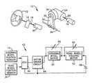
- FIG. 1is a schematic illustration of steering apparatus constructed in accordance with the present invention and illustrating the relationship between a steering wheel motor and a steering wheel and the relationship between a road wheel steering motor and apparatus for effecting steering movement of steerable road engaging wheels;
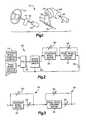
- FIG. 2is a schematic block diagram of an electrical circuit of the steering apparatus illustrated in FIG. 1;
- FIG. 3is a schematic diagram of a portion of the circuit of FIG. 2 and illustrating the relationship of variable resistors to the steering wheel motor and road wheel steering motor in the apparatus of FIG. 1;
- FIG. 4is a cross-sectional view of a hydraulic motor which is connected with the road wheel steering motor and with the steerable vehicle wheels;
- FIG. 5is a sectional view of an alternative embodiment of the apparatus of FIG. 1 and illustrating the relationship of the road wheel steering motor to a drive mechanism connected with steerable road-engaging wheels of a vehicle.
- the present inventionis embodied in a steering apparatus generally designated 10 in FIG. 1 .
- the steering apparatus 10includes a steering wheel 12 which is turned manually by the driver in the vehicle.
- a suitable steering wheel position sensor 14senses the angular position of the steering wheel 12 .
- the steering wheel position sensor 14provides an output signal dependent upon the amount of rotation of the steering wheel 12 and the angular position of the steering wheel.
- the output signal from the steering wheel position sensor 14controls an electric road wheel steering motor 16 .
- the steering wheel position sensor 14may be any suitable known sensor.
- the road wheel steering motor 16may be any suitable variable speed reversible electric motor.
- Rotation of the steering wheel 12causes rotation of a shaft 18 which is connected with the position sensor 14 .
- the shaft 18is connected with an electric steering wheel motor 20 which is constructed to resist turning of the shaft by the driver of the vehicle.
- the steering wheel motor 20may be any suitable variable speed reversible electric motor.
- the steering apparatus 10is a steer-by-wire system.
- the steering apparatus 10has no mechanical connection between the steering wheel 12 and a steering gear 24 which is operatively coupled with at least one steerable road-engaging wheel (not shown) on the end of a vehicle axle (not shown).
- the steering gear 24may be of any suitable construction.
- the road wheel motor 16is connected with the steering gear 24 by an input shaft 26 .
- the steering gear 24(FIG. 1) is connected with the steerable road-engaging wheels of the vehicle by an output shaft 30 which is connected with a pitman arm 32 .
- the pitman arm 32is connected with the steerable vehicle wheels by a steering linkage 34 .
- a road wheel position sensor 36senses the output position of the steering gear 24 and, as a result, senses the position of the pitman arm 32 and steerable road-engaging wheels.
- the road wheel position sensor 36is connected with the output shaft 30 from the steering gear 24 .
- the road wheel position sensor 36may be any suitable position sensor, including an optical sensor or an electrical sensor.
- the steering wheel position sensor 14Upon rotation of the steering wheel 12 , the steering wheel position sensor 14 provides an output signal to an electronic control unit 42 (FIG. 2) in control circuitry 43 .
- the electronic control unit 42determines the desired road wheel position as a function of the position of the steering wheel 12 .
- the electronic control unit 42may include a variable ratio function which calculates the demanded road wheel position based on steering wheel position.
- the variable ratio functionpermits a non-linear relationship between road wheel position and steering wheel position.
- the variable ratio function in the electronic control unit 42can use algorithms or lookup tables to perform the calculation of road wheel position.
- the electronic control unit 42also receives a signal from the road wheel position sensor 36 .
- the electronic control unit 42determines any errors between the position of the steering wheel and the position of the steerable road-engaging wheels of the vehicle. In response to detection of a difference between the position of the steering wheel 12 and the positions of road-engagable steerable vehicle wheels, the electronic control unit 42 actuates a motor drive circuit 44 to effect energization of the steering wheel motor 20 and the road wheel steering motor 16 .
- the electronic control unit 42effects operation of the steering wheel motor 20 to resist rotation of the steering wheel 12 with a force which varies as a function of variations in the difference between the position of the steering wheel and the positions of the steerable road-engaging wheels of the vehicle.
- the electronic control unit 42effects operation of the road wheel steering motor 16 to drive the steering gear 24 to actuate the steering linkage 34 and effect turning movement of the steerable road-engaging wheels of the vehicle to a position corresponding to the position of the steering wheel 12 .
- a vehicle battery 48provides power to effect operation of the steering wheel motor 20 and road-wheel steering motor 16 .
- the steering wheel motor 20 and road wheel steering motor 16are preferably identical in construction and have motor windings connected in series. Therefore, the torque with which the steering wheel motor 20 resists rotation of the steering wheel 12 is the same as the torque which is applied by the road wheel steering motor 16 to the steering gear 24 . Although the steering wheel motor 20 and road wheel steering motor 16 have the same output torque, the force which is transmitted from the road wheel steering motor 16 through the steering gear 24 and steering linkage 34 to the steerable road-engaging wheels of the vehicle is substantially greater than the force applied to the shaft 18 resisting rotation of the steering wheel 12 .
- the force which is applied to the shaft 18 resisting rotation of the steering wheel 12varies as a function of variations in the force applied by the road wheel steering motor 16 to the input shaft 26 to the steering gear 24 . Therefore, the force provided by the steering wheel motor 20 to resist rotation of the steering wheel 12 varies as a direct function of the force which is transmitted to the steerable road engaging wheels of the vehicle through the steering linkage 34 . Of course, the force which effects turning movement of the steerable road-engaging vehicle wheels is greater than the force which resists turning movement of the steering wheel 12 .
- the driver of the vehiclefeels a resistance to turning movement of the steering wheel 12 which is a function of the resistance encountered by the steerable vehicle wheels to turning movement of the wheels.
- the torque applied by the steering wheel motor 20 to the steering wheel 12makes the operator feel as though there is a mechanical connection between the steering wheel 12 and the steering gear 24 .
- control circuitry 43 of FIG. 2could have many different constructions, it is believed that it may be desired to provide the electrical circuitry with the same construction as is disclosed in the aforementioned International Patent Application Ser. No. PCT/US01/10566 filed Mar. 30, 2001 disclosing subject matter invented by Daniel E. Williams and assigned to TRW Inc. As was previously mentioned, International Patent Application Ser. No. PCT/US01/10566 claims the benefit of U.S. Provisional Application Ser. No. 60/194,132 filed Apr. 3, 2000.
- variable resistorsare provided in association with the steering wheel motor 20 .
- the variable resistors 54 connected with the steering wheel motor 20enable the output of the steering wheel motor to be varied to vary the resistance provided by the steering wheel motor to rotation of the steering wheel 12 .
- the variable resistors 54enables the output torque of the steering wheel motor 20 to be changed without changing the output torque of the road wheel steering motor 16 .
- Variable resistors 56are connected with the road wheel steering motor 16 .
- the variable resistors 56enable the output of the road wheel steering motor 16 to be varied to vary the force transmitted to the steering gear 24 . Varying the force transmitted to the steering gear 24 is effective to vary the force transmitted from the steering gear through the steering linkage 34 to the steerable road-engaging wheels of the vehicle. By varying the force transmitted to the steerable road-engaging wheels of vehicle in response to rotation of the steering wheel 12 , the amount of assistance provided by the road wheel steering motor 16 and steering gear 24 to incremental rotation of the steering wheel 12 can be varied.
- the variable resistors 56enable the output torque of the road wheel steering motor 16 to be changed without changing the output torque of the steering wheel motor 20 .
- variable resistors 54 and 56(FIG. 3) will be set when the steering apparatus 10 is installed in the vehicle.
- controlscould be provided in the vehicle to enable an operator to vary the settings of the variable resistors 54 and 56 if desired.
- controlscould be provided at a relatively inaccessible location in the vehicle to enable maintenance personnel to vary the settings of the resistors 54 and 56 if desired.
- variable resistors 54 connected with the steering wheel motor 20include a variable resistor 60 connected in parallel with the steering wheel motor 20 and a variable resistor 62 connected in series with the steering wheel motor 20 .
- variable resistors 56 connected with the road wheel steering motor 16include a variable resistor 66 connected in parallel with the road wheel steering motor 16 .
- a variable resistor 68is connected in series with the road wheel steering motor 16 .
- variable resistors 60 and 66are adjustable to change the amount of current which is bypassed around the steering wheel motor 20 and road wheel steering motor 16 . Changing the amount of current which is bypassed around the steering wheel motor 20 and the road wheel steering motor 16 is effective to vary the output torque of the steering wheel motor and the road wheel steering motor. Adjusting the variable resistor 60 to adjust the current conducted through the steering wheel motor 20 does not change the current conducted through the road wheel steering motor 16 . Similarly, adjusting the variable resistor 66 to adjust the current conducted through the road wheel steering motor 16 does not change the current conducted through the steering wheel motor 20 .
- variable resistor 60When the output torque of the steering wheel motor 20 is to be adjusted, the variable resistor 60 is adjusted. By increasing the resistance of the variable resistor 60 , the amount of current which is conducted from the motor driver circuit 44 through the steering wheel motor 20 is increased. Of course, increasing the current conducted through the steering wheel motor 20 increases the output torque of the motor and the resistance to rotation of the steering wheel 12 . Conversely, decreasing the resistance of the variable resistor 60 is effective to decrease the amount of current which is conducted through the steering wheel motor 20 . Decreasing the amount of current which is conducted through the steering wheel motor 20 decreases both the output torque of the motor and the amount of resistance to rotation of the steering wheel 12 .
- the variable resistor 62is adjustable to limit recirculation of current from the steering wheel motor 20 through the variable resistor 60 .
- variable resistor 66By increasing the resistance of the variable resistor 66 , the amount of current conducted through the road wheel steering motor 16 is increased. Increasing the amount of current conducted through the road wheel steering motor 16 increases the output torque transmitted from the road wheel steering motor 16 to the steering gear 24 (FIG. 1 ). Decreasing the resistance of the variable resistor 66 (FIG. 3) increases the current which bypasses the road wheel steering motor 16 . Increasing the current which bypasses the road wheel steering motor 16 decreases the output torque transmitted from the road wheel steering motor 16 to the steering gear 24 (FIG. 1 ).
- the steering gear 24(FIG. 1) is operated in response to operation of the steering wheel motor 16 to drive the steering linkage 34 . It is contemplated that the steering gear 24 could have any one of many different constructions. In the embodiment of the invention illustrated in FIG. 4, the steering gear 24 is an integral hydraulic power steering gear.
- the integral hydraulic power steering gear 24includes a two-piece housing 82 (FIG. 2) having a hydraulic power cylinder 84 .
- the power cylinder 84comprises a chamber 86 divided into two chamber portions 88 and 90 , respectively, by a piston 92 .
- the piston 92includes an inner bore 93 with a helical groove 94 .
- the piston 92also has a set of external teeth 95 which mesh with a sector gear 96 .
- the sector gear 96is fixed to an output shaft 30 which extends outwardly from the housing 82 .
- the output shaft 30is connected to a pitman arm 32 (FIG. 1) which, in turn, is connected via steering linkage 34 to the steerable wheels to steer the vehicle.
- the output shaft 30is rotated to operate the steering linkage 34 , which turns the steerable wheels of the vehicle.
- a hydraulic control valve assembly 100(FIG. 2) controls the flow of pressurized hydraulic fluid between a hydraulic circuit including a hydraulic pump (not shown) and one of the chamber portions 88 and 90 to control the direction and amount of steering.
- the valve assembly 100is actuated by a rotatable input shaft 26 .
- the input shaft 26(FIGS. 1 and 4) is rotated by the electric motor 16 .
- the valve assembly 100(FIG. 4) comprises first and second valve members 104 and 106 , respectively.
- the first valve member 104comprises a valve core 110 and the second valve member 106 comprises a valve sleeve 112 .
- the valve core 110is located coaxially within the valve sleeve 112 and is supported for rotation by the valve sleeve.
- the valve core 110is formed integrally as one piece with the input shaft 26 .
- the valve core 110has oppositely disposed first and second end portions 114 and 116 , respectively, and a valve section 118 between the end portions.
- the first end portion 114 of the valve core 110projects beyond the valve sleeve 112 and the second end portion 116 of the valve core lies within the valve sleeve.
- the valve section 118 of the valve core 110has a plurality of circumferentially spaced, axially extending grooves 120 as is known in the art.
- a first portion of the grooves 120are fluidly connected with an internal passage 122 extending from the valve section 118 of the valve core 110 to the second end portion 116 .
- the internal passage 122communicates via passages (not shown) with the return line of a hydraulic pump circuit (not shown).
- a second portion of the grooves 120are in fluid communication with a plurality of passages 124 in the valve sleeve 112 .
- the valve sleeve 112has oppositely disposed first and second ends 130 and 132 , respectively.
- the valve sleeve 112further includes a sleeve section 134 adjacent the first end 130 and a ball screw section 136 adjacent the second end 132 .
- An axially extending passage 138extends from the first end 130 of the valve sleeve 112 through the sleeve section 134 and the ball screw section 136 to the second end 132 .
- the first end 130 of the valve sleeve 112includes first and second lugs (not shown) that are disposed in diametrically opposed cut-outs (not shown) in the valve core 110 .
- the lugsengage the cut-outs in the valve core to cause the, valve sleeve to be rotated along with the valve core.
- Such rotation of the valve sleeve 112causes the piston 92 to move axially in the chamber 86 and, hence, allows for manual steering of the vehicle even if a loss in hydraulic fluid pressure has occurred.
- the sleeve section 134 (FIG. 4) of the valve sleeve 112includes the plurality of passages 124 which extend from the outer circumference of the sleeve section to the inner circumference.
- the passages 124communicate with an annular chamber 140 in the housing 82 which is fluidly connected to the hydraulic pump.
- a plurality of axially extending grooves 142are formed in the inner surface of the valve sleeve 112 as is known in the art.
- the grooves 142fluidly communicate with the second portion of the grooves 120 in the valve core 110 .
- a first portion of the grooves 142 in the valve sleeve 112are fluidly connected via passages (not shown) with the first chamber portion 88 in the housing 82 , and a second portion of the grooves 142 fluidly connected via passages (not shown) with the second chamber portion 90 in the housing.
- hydraulic fluidis ported through the grooves 120 and 142 and associated passages to one of the chamber portions 80 and 90 , while the hydraulic fluid is vented from the other chamber portion, thereby causing the piston 92 to move accordingly.
- the ball screw section 136 (FIG. 4) of the valve sleeve 112includes a helical groove 144 formed on its outer periphery.
- a plurality of balls 146are located in the helical groove 144 .
- the balls 146are also located in the helical groove 94 in the bore 93 formed in the piston 92 .
- axial movement of the piston 92causes the ball screw portion 136 to rotate which, in turn, causes the rest of the valve sleeve 112 to rotate.
- a torsion bar 148connects the valve core 110 and the valve sleeve 112 .
- One end of the torsion bar 148is connected by a pin 150 to the valve section 118 of the valve core 110 , while the other end of the torsion bar extends through the passage 138 in the valve sleeve 112 and is connected by a pin 152 adjacent the second end 132 of the valve sleeve.
- actuation of the motor 16causes rotation of the valve core 110 of the steering gear 24 relative to the valve sleeve 112 .
- Rotation of the valve core 112causes axial movement of the piston 92 in one direction or the other.
- Axial movement of the piston 92results in rotation of the sector gear 96 and the pitman arm 32 , thereby causing the road-engaging steerable wheels to turn laterally of the vehicle.
- the steering gear 24includes a hydraulically actuated motor which drives a sector gear 96 .
- the road wheel steering motor 16is connected directly with the steering gear 24 .
- the steering gear 24is, in turn, connected directly to the steering linkage 34 (FIG. 1 ).
- the steering gear 24 of FIG. 5utilizes mechanical devices to effect a multiplication of the force provided by the road wheel steering motor 16 to drive the steering linkage 34 and effect turning movement of the steerable road-engaging vehicle wheels.
- the steering gear 24includes a linearly movable steering member 232 (FIG. 5) that extends axially through a housing 231 .
- the steering member 232is linearly (or axially) movable along an axis 234 .
- the steering member 232includes a screw portion 240 having an external thread convolution.
- the steering member 232is connected with tie rods 242 which form part of the steering linkage 34 (FIG. 1 ).
- the steering linkage 34is connected with the steerable wheels (not shown) of the vehicle through the tie rods 242 (FIG. 5) located at the distal ends of the steering member 232 .
- Linear movement of the steering member 232 along the axis 234results in steering movement of the steerable wheels as is known in the art.
- the housing 231has a generally cylindrical configuration including an axially extending side wall 250 centered on the axis 234 .
- a radially enlarged section 252 of the housing 231is located at the right end (as viewed in FIG. 5) of the housing 231 .
- the radially enlarged section 252 of the housing 231defines an annular chamber 254 .
- An outboard housing 258is attached, in a manner not shown, to the radially enlarged section 252 of the housing 231 and closes the chamber 254 .
- a ball nut assembly 270is located in the chamber 254 in the radially enlarged section 252 of the housing 231 and encircles the screw portion 240 of the steering member 232 .
- the ball nut assembly 270includes a ball nut 272 , a plurality of force transmitting members or balls 274 , a first bearing assembly 276 , a gear member 278 , and a lock nut 280 .
- the lock nut 280screws onto the ball nut 272 to axially secure the parts of the ball nut assembly 270 .
- the plurality of force-transmitting members 274comprise balls disposed between the internal screw thread convolution of the ball nut 272 and the external thread convolution on the screw portion 240 of the steering member 232 .
- the ball nut assembly 270includes a recirculation passage (not shown) for recirculating the balls upon axial movement of the steering member 232 relative to the ball nut assembly.
- the ball nut assembly 270provides a gear reduction ratio as is known in the art.
- the road wheel steering motor 16is mounted to a radially extending gearbox portion 222 of the housing 231 .
- the gearbox portion 222extends from the radially enlarged section 252 of the housing 231 .
- the gearbox portion 222contains meshed first and second gears 278 and 224 , respectively.
- the first gearis the gear member 278 of the ball nut assembly 270 .
- the second gear 226is connected for rotation with the motor output shaft 203 extending from the road wheel steering motor 16 .
- the meshed first and second gears 278 and 226provide a gear reduction ratio between the motor output shaft 203 of the electric motor 16 and the ball nut assembly 270 .
- the motor 16extends transverse to the steering member 232 at a right angle. It is contemplated, however, that the motor 16 could lie parallel to the steering member 232 or at a different angle, such as 450 , relative to the steering member.
- the steering gear 24further includes a plurality of output position sensors 36 , illustrated schematically in FIG. 5, for sensing the amount of rotation of the ball nut 270 .
- the position sensors 36are non-contacting sensors. There are a multiplicity of output position sensors 36 for redundancy purposes.
- the electronic control unit 42is operable to generate a signal corresponding to the rotation of the ball nut 270 sensed by the position sensors 36 .
- the steering gear 24has a construction which is generally similar to the construction of the steering gear disclosed in the aforementioned International Patent Application Ser. No. PCT/US01/40392 filed Mar. 29, 2001 assigned to TRW Inc. and containing subject matter invented by William A. Szabela. Although one specific form of steering gear 24 has been illustrated in FIG. 5 and a different form of the steering gear has been illustrated in FIG. 4, it is contemplated that the steering gear could have a construction which is different than either of these two exemplary constructions.
Landscapes
- Engineering & Computer Science (AREA)
- Chemical & Material Sciences (AREA)
- Combustion & Propulsion (AREA)
- Transportation (AREA)
- Mechanical Engineering (AREA)
- Power Steering Mechanism (AREA)
- Steering Control In Accordance With Driving Conditions (AREA)
Abstract
Description
Claims (4)
Priority Applications (3)
| Application Number | Priority Date | Filing Date | Title |
|---|---|---|---|
| US09/950,066US6547029B2 (en) | 2001-09-10 | 2001-09-10 | Vehicle steering apparatus |
| PCT/US2002/028797WO2003022659A1 (en) | 2001-09-10 | 2002-09-10 | Vehicle steering apparatus |
| EP02770495AEP1439994A4 (en) | 2001-09-10 | 2002-09-10 | Vehicle steering apparatus |
Applications Claiming Priority (1)
| Application Number | Priority Date | Filing Date | Title |
|---|---|---|---|
| US09/950,066US6547029B2 (en) | 2001-09-10 | 2001-09-10 | Vehicle steering apparatus |
Publications (2)
| Publication Number | Publication Date |
|---|---|
| US20030047374A1 US20030047374A1 (en) | 2003-03-13 |
| US6547029B2true US6547029B2 (en) | 2003-04-15 |
Family
ID=25489892
Family Applications (1)
| Application Number | Title | Priority Date | Filing Date |
|---|---|---|---|
| US09/950,066Expired - LifetimeUS6547029B2 (en) | 2001-09-10 | 2001-09-10 | Vehicle steering apparatus |
Country Status (3)
| Country | Link |
|---|---|
| US (1) | US6547029B2 (en) |
| EP (1) | EP1439994A4 (en) |
| WO (1) | WO2003022659A1 (en) |
Cited By (13)
| Publication number | Priority date | Publication date | Assignee | Title |
|---|---|---|---|---|
| US20030141135A1 (en)* | 2002-01-30 | 2003-07-31 | Ratko Menjak | Drive-by-wire steering systems having a center feel mechanism and methods of providing |
| US20030146037A1 (en)* | 2002-02-05 | 2003-08-07 | Ratko Menjak | Hand wheel actuator |
| US20040020706A1 (en)* | 2000-04-03 | 2004-02-05 | Williams Daniel E. | Steer-by-wire steering system with road feel |
| US6857496B2 (en) | 2002-09-03 | 2005-02-22 | Trw Inc. | Vehicle steering apparatus with anti-steer security device |
| US6938720B2 (en)* | 2002-05-09 | 2005-09-06 | Delphi Technologies, Inc. | Steering input devices for steer-by-wire systems |
| US20070080015A1 (en)* | 2005-10-11 | 2007-04-12 | Trw Automotive U.S. Llc | Closed center steering system |
| US20080053740A1 (en)* | 2006-08-30 | 2008-03-06 | Agco Sa | Vehicle steering systems |
| WO2008039837A3 (en)* | 2006-09-26 | 2008-11-20 | D & R Technologies L L C | Steering wheel position sensor |
| US20100072738A1 (en)* | 2008-09-19 | 2010-03-25 | Trw Automotive U.S. Llc | Steering System |
| US20100071988A1 (en)* | 2008-09-19 | 2010-03-25 | Trw Automotive U.S. Llc | Apparatus for use in turning steerable vehicle wheels |
| US8567554B2 (en)* | 2011-03-23 | 2013-10-29 | GM Global Technology Operations LLC | Recirculating ball power steering system |
| US11279400B1 (en) | 2018-01-02 | 2022-03-22 | RBR Enterprise, LLC | Adjustable wheel track axle with independent wheel angle control for an agricultural vehicle |
| US20240034392A1 (en)* | 2019-05-14 | 2024-02-01 | Hl Mando Corporation | Vehicle steering apparatus |
Families Citing this family (11)
| Publication number | Priority date | Publication date | Assignee | Title |
|---|---|---|---|---|
| DE10331597A1 (en)* | 2003-07-11 | 2005-02-03 | Zf Lenksysteme Gmbh | Actuator, in particular Radaktuator with an output |
| JP2005075117A (en)* | 2003-08-29 | 2005-03-24 | Favess Co Ltd | Electric power steering device |
| JP4411952B2 (en)* | 2003-12-04 | 2010-02-10 | 株式会社ジェイテクト | Vehicle steering system |
| US7017689B2 (en)* | 2004-05-06 | 2006-03-28 | Crown Equipment Corporation | Electrical steering assist for material handling vehicles |
| BR112015022380A2 (en) | 2013-03-14 | 2017-07-18 | Crown Equip Corp | system to provide electrical steering assistance for a material handling vehicle |
| DE102018119977A1 (en)* | 2018-08-16 | 2020-02-20 | Thyssenkrupp Ag | Steering gear for a steer-by-wire steering system |
| DE102018120266A1 (en) | 2018-08-21 | 2020-02-27 | Thyssenkrupp Ag | Steer-by-wire steering gear with hollow shaft motor and ball screw |
| JP7185536B2 (en)* | 2019-01-09 | 2022-12-07 | 株式会社Subaru | rotor drive |
| DE102019127953A1 (en)* | 2019-10-16 | 2021-04-22 | Knorr-Bremse Steeringsystems GmbH | Steering gear for an electromechanical steering system for a vehicle and an electromechanical steering system for a vehicle |
| CN114771647B (en)* | 2022-06-21 | 2022-10-21 | 太原理工大学 | Helical variable transmission ratio mechanism, electro-hydraulic power steering system and method using the same |
| CA3209767A1 (en)* | 2022-09-28 | 2024-03-28 | Toyota Material Handling, Inc. | Synchronized steering control systems for forklifts |
Citations (17)
| Publication number | Priority date | Publication date | Assignee | Title |
|---|---|---|---|---|
| US1979890A (en)* | 1934-01-15 | 1934-11-06 | Lee Engineering Res Corp | Motor controlling apparatus |
| US3559019A (en)* | 1967-03-27 | 1971-01-26 | Janome Sewing Machine Co Ltd | Speed control system of a motor and a circuit therefor |
| JPS6460278A (en)* | 1987-08-31 | 1989-03-07 | Canon Denshi Kk | Drive circuit for dc motor |
| US4830127A (en) | 1985-12-27 | 1989-05-16 | Nissan Motor Company, Ltd. | System and method for controlling a steering reaction force imposed on a steering wheel |
| US4860844A (en) | 1988-04-29 | 1989-08-29 | Eaton Corporation | Power steering system |
| US4865144A (en) | 1988-04-29 | 1989-09-12 | Eaton Corporation | Power steering system having simulated torque sensor |
| US5228757A (en) | 1990-07-02 | 1993-07-20 | Nissan Motor Co., Ltd. | System for controlling behavior of vehicle during braking and during a steering maneuver |
| US5247441A (en) | 1990-09-25 | 1993-09-21 | Honda Giken Kogyo Kabushiki Kaisha | Vehicle steering control system |
| US5252135A (en) | 1991-07-02 | 1993-10-12 | Chugai Ro Co., Ltd. | Sealing apparatus for continuous vacuum treating equipment |
| US5347458A (en) | 1990-09-25 | 1994-09-13 | Honda Giken Kogyo Kabushiki Kaisha | Vehicle steering control system |
| US5511629A (en) | 1993-02-16 | 1996-04-30 | Daimler-Benz Ag | Motor vehicle steering system |
| US5709281A (en) | 1995-09-14 | 1998-01-20 | Trw Inc. | Method and apparatus for adjusting steering feel |
| US5880367A (en) | 1996-07-11 | 1999-03-09 | First Inertia Switch Limited | Vehicle steering sensor device |
| US5925083A (en) | 1996-12-07 | 1999-07-20 | Deutsche Forchungsanstalt Fur Luft Und Raumfahrt E.V. | Method of correcting steering of a road driven vehicle |
| US6097286A (en) | 1997-09-30 | 2000-08-01 | Reliance Electric Technologies, Llc | Steer by wire system with feedback |
| US6098296A (en) | 1998-12-03 | 2000-08-08 | Delco Electronics Corp. | Wheel alignment system and method for vehicles having steer-by-wire steering system |
| US6397971B1 (en)* | 1999-12-16 | 2002-06-04 | Mitsubishi Denki Kabushiki Kaisha | Electrically powered steering system |
Family Cites Families (4)
| Publication number | Priority date | Publication date | Assignee | Title |
|---|---|---|---|---|
| CH366320A (en)* | 1961-03-27 | 1962-12-31 | Baumgartner Freres Sa | Device for stabilizing the speed of rotation of an electric motor supplied with direct current |
| CH430843A (en)* | 1964-07-21 | 1967-02-28 | Deutsche Post Rundfunk | Circuit arrangement for influencing the speed of a direct current motor |
| JPS61269688A (en)* | 1985-05-23 | 1986-11-29 | Mabuchi Motor Co Ltd | Speed controller of dc motor |
| DE19820774A1 (en)* | 1998-05-08 | 1999-11-18 | Danfoss As | Hydraulic wheeled machine with road feedback |
- 2001
- 2001-09-10USUS09/950,066patent/US6547029B2/ennot_activeExpired - Lifetime
- 2002
- 2002-09-10EPEP02770495Apatent/EP1439994A4/ennot_activeWithdrawn
- 2002-09-10WOPCT/US2002/028797patent/WO2003022659A1/ennot_activeApplication Discontinuation
Patent Citations (17)
| Publication number | Priority date | Publication date | Assignee | Title |
|---|---|---|---|---|
| US1979890A (en)* | 1934-01-15 | 1934-11-06 | Lee Engineering Res Corp | Motor controlling apparatus |
| US3559019A (en)* | 1967-03-27 | 1971-01-26 | Janome Sewing Machine Co Ltd | Speed control system of a motor and a circuit therefor |
| US4830127A (en) | 1985-12-27 | 1989-05-16 | Nissan Motor Company, Ltd. | System and method for controlling a steering reaction force imposed on a steering wheel |
| JPS6460278A (en)* | 1987-08-31 | 1989-03-07 | Canon Denshi Kk | Drive circuit for dc motor |
| US4860844A (en) | 1988-04-29 | 1989-08-29 | Eaton Corporation | Power steering system |
| US4865144A (en) | 1988-04-29 | 1989-09-12 | Eaton Corporation | Power steering system having simulated torque sensor |
| US5228757A (en) | 1990-07-02 | 1993-07-20 | Nissan Motor Co., Ltd. | System for controlling behavior of vehicle during braking and during a steering maneuver |
| US5347458A (en) | 1990-09-25 | 1994-09-13 | Honda Giken Kogyo Kabushiki Kaisha | Vehicle steering control system |
| US5247441A (en) | 1990-09-25 | 1993-09-21 | Honda Giken Kogyo Kabushiki Kaisha | Vehicle steering control system |
| US5252135A (en) | 1991-07-02 | 1993-10-12 | Chugai Ro Co., Ltd. | Sealing apparatus for continuous vacuum treating equipment |
| US5511629A (en) | 1993-02-16 | 1996-04-30 | Daimler-Benz Ag | Motor vehicle steering system |
| US5709281A (en) | 1995-09-14 | 1998-01-20 | Trw Inc. | Method and apparatus for adjusting steering feel |
| US5880367A (en) | 1996-07-11 | 1999-03-09 | First Inertia Switch Limited | Vehicle steering sensor device |
| US5925083A (en) | 1996-12-07 | 1999-07-20 | Deutsche Forchungsanstalt Fur Luft Und Raumfahrt E.V. | Method of correcting steering of a road driven vehicle |
| US6097286A (en) | 1997-09-30 | 2000-08-01 | Reliance Electric Technologies, Llc | Steer by wire system with feedback |
| US6098296A (en) | 1998-12-03 | 2000-08-08 | Delco Electronics Corp. | Wheel alignment system and method for vehicles having steer-by-wire steering system |
| US6397971B1 (en)* | 1999-12-16 | 2002-06-04 | Mitsubishi Denki Kabushiki Kaisha | Electrically powered steering system |
Cited By (21)
| Publication number | Priority date | Publication date | Assignee | Title |
|---|---|---|---|---|
| US20040020706A1 (en)* | 2000-04-03 | 2004-02-05 | Williams Daniel E. | Steer-by-wire steering system with road feel |
| US6973989B2 (en)* | 2000-04-03 | 2005-12-13 | Trw Inc. | Steer-by-wire steering system with road feel |
| US6705419B2 (en)* | 2002-01-30 | 2004-03-16 | Delphi Technologies, Inc. | Drive-by-wire steering systems having a center feel mechanism and methods of providing |
| US20030141135A1 (en)* | 2002-01-30 | 2003-07-31 | Ratko Menjak | Drive-by-wire steering systems having a center feel mechanism and methods of providing |
| US20030146037A1 (en)* | 2002-02-05 | 2003-08-07 | Ratko Menjak | Hand wheel actuator |
| US6799654B2 (en)* | 2002-02-05 | 2004-10-05 | Delphi Technologies, Inc. | Hand wheel actuator |
| US6938720B2 (en)* | 2002-05-09 | 2005-09-06 | Delphi Technologies, Inc. | Steering input devices for steer-by-wire systems |
| US6857496B2 (en) | 2002-09-03 | 2005-02-22 | Trw Inc. | Vehicle steering apparatus with anti-steer security device |
| US20070080015A1 (en)* | 2005-10-11 | 2007-04-12 | Trw Automotive U.S. Llc | Closed center steering system |
| US7484588B2 (en) | 2005-10-11 | 2009-02-03 | Trw Automotive U.S. Llc | Closed center steering system |
| US7686124B2 (en)* | 2006-08-30 | 2010-03-30 | Agco Sa | Vehicle steering systems |
| US20080053740A1 (en)* | 2006-08-30 | 2008-03-06 | Agco Sa | Vehicle steering systems |
| WO2008039837A3 (en)* | 2006-09-26 | 2008-11-20 | D & R Technologies L L C | Steering wheel position sensor |
| US20100114523A1 (en)* | 2006-09-26 | 2010-05-06 | Waite Daryn L | Steering wheel position sensor |
| US8326570B2 (en) | 2006-09-26 | 2012-12-04 | D&R Technologies, L.L.C. | Steering wheel position sensor |
| US20100071988A1 (en)* | 2008-09-19 | 2010-03-25 | Trw Automotive U.S. Llc | Apparatus for use in turning steerable vehicle wheels |
| US20100072738A1 (en)* | 2008-09-19 | 2010-03-25 | Trw Automotive U.S. Llc | Steering System |
| US7909132B2 (en)* | 2008-09-19 | 2011-03-22 | Trw Automotive U.S. Llc | Apparatus for use in turning steerable vehicle wheels |
| US8567554B2 (en)* | 2011-03-23 | 2013-10-29 | GM Global Technology Operations LLC | Recirculating ball power steering system |
| US11279400B1 (en) | 2018-01-02 | 2022-03-22 | RBR Enterprise, LLC | Adjustable wheel track axle with independent wheel angle control for an agricultural vehicle |
| US20240034392A1 (en)* | 2019-05-14 | 2024-02-01 | Hl Mando Corporation | Vehicle steering apparatus |
Also Published As
| Publication number | Publication date |
|---|---|
| EP1439994A1 (en) | 2004-07-28 |
| WO2003022659A1 (en) | 2003-03-20 |
| US20030047374A1 (en) | 2003-03-13 |
| EP1439994A4 (en) | 2004-12-22 |
Similar Documents
| Publication | Publication Date | Title |
|---|---|---|
| US6547029B2 (en) | Vehicle steering apparatus | |
| US6575263B2 (en) | Torque device for electronic steer-by wire steering systems | |
| US6298941B1 (en) | Electro-hydraulic power steering system | |
| US6360841B1 (en) | Power steering mechanism with magnetoelastic torsion bar | |
| US6923288B2 (en) | Electric steering apparatus | |
| US6655709B2 (en) | Steer-by-wire steering apparatus with actuatable mechanism | |
| US5511630A (en) | Power steering system | |
| US8534414B2 (en) | Steering apparatus for a vehicle having front and rear steerable wheels | |
| US6973989B2 (en) | Steer-by-wire steering system with road feel | |
| WO2002102640A2 (en) | Steer-by-wire-handwheel actuator | |
| US5156228A (en) | Front wheel steering apparatus | |
| JP2002519245A (en) | Hydraulic assist power steering | |
| US7240760B2 (en) | Steering apparatus | |
| CN113147888B (en) | Steering gear, power-assisted steering system and crane | |
| US9102354B2 (en) | Apparatus for use in turning steerable vehicle wheels | |
| CA2556401C (en) | Steering system for a vehicle | |
| US8069945B2 (en) | Method and apparatus for rear wheel steering control | |
| US7484588B2 (en) | Closed center steering system | |
| US6035957A (en) | Power steering control valve balancing | |
| JP3763562B2 (en) | Steering device | |
| EP0414213B1 (en) | Hydraulic power steering apparatus for industrial vehicle | |
| US20090314572A1 (en) | Closed center valve steering system with adjustable pressure | |
| JPH0518227Y2 (en) | ||
| US6253657B1 (en) | Steering apparatus |
Legal Events
| Date | Code | Title | Description |
|---|---|---|---|
| AS | Assignment | Owner name:TRW INC., OHIO Free format text:ASSIGNMENT OF ASSIGNORS INTEREST;ASSIGNORS:PEPPLER, STEVEN;SZABELA, WILLIAM A.;REEL/FRAME:012163/0115;SIGNING DATES FROM 20010829 TO 20010831 | |
| FEPP | Fee payment procedure | Free format text:PAYOR NUMBER ASSIGNED (ORIGINAL EVENT CODE: ASPN); ENTITY STATUS OF PATENT OWNER: LARGE ENTITY Free format text:PAYER NUMBER DE-ASSIGNED (ORIGINAL EVENT CODE: RMPN); ENTITY STATUS OF PATENT OWNER: LARGE ENTITY | |
| STCF | Information on status: patent grant | Free format text:PATENTED CASE | |
| AS | Assignment | Owner name:JPMORGAN CHASE BANK, NEW YORK Free format text:THE US GUARANTEE AND COLLATERAL AGREEMENT;ASSIGNOR:TRW AUTOMOTIVE U.S. LLC;REEL/FRAME:014022/0720 Effective date:20030228 | |
| FPAY | Fee payment | Year of fee payment:4 | |
| FPAY | Fee payment | Year of fee payment:8 | |
| AS | Assignment | Owner name:JPMORGAN CHASE BANK, N.A., AS COLLATERAL AGENT, NE Free format text:SECURITY AGREEMENT;ASSIGNORS:TRW VEHICLE SAFETY SYSTEMS INC.;TRW AUTOMOTIVE U.S. LLC;KELSEY-HAYES COMPANY;REEL/FRAME:029529/0534 Effective date:20120928 | |
| AS | Assignment | Owner name:TRW INTELLECTUAL PROPERTY CORP., MICHIGAN Free format text:RELEASE OF SECURITY INTEREST;ASSIGNOR:JPMORGAN CHASE BANK, N.A.;REEL/FRAME:031645/0697 Effective date:20131028 Owner name:TRW AUTOMOTIVE U.S. LLC, MICHIGAN Free format text:RELEASE OF SECURITY INTEREST;ASSIGNOR:JPMORGAN CHASE BANK, N.A.;REEL/FRAME:031645/0697 Effective date:20131028 Owner name:TRW VEHICLE SAFETY SYSTEMS INC., MICHIGAN Free format text:RELEASE OF SECURITY INTEREST;ASSIGNOR:JPMORGAN CHASE BANK, N.A.;REEL/FRAME:031645/0697 Effective date:20131028 Owner name:KELSEY-HAYES COMPANY, MICHIGAN Free format text:RELEASE OF SECURITY INTEREST;ASSIGNOR:JPMORGAN CHASE BANK, N.A.;REEL/FRAME:031645/0697 Effective date:20131028 | |
| FPAY | Fee payment | Year of fee payment:12 |