US6547000B1 - Heat exchange for a film heat exchanger and a method for manufacturing the same - Google Patents
Heat exchange for a film heat exchanger and a method for manufacturing the sameDownload PDFInfo
- Publication number
- US6547000B1 US6547000B1US09/341,855US34185500AUS6547000B1US 6547000 B1US6547000 B1US 6547000B1US 34185500 AUS34185500 AUS 34185500AUS 6547000 B1US6547000 B1US 6547000B1
- Authority
- US
- United States
- Prior art keywords
- films
- heat exchange
- film
- bonding
- interior
- Prior art date
- Legal status (The legal status is an assumption and is not a legal conclusion. Google has not performed a legal analysis and makes no representation as to the accuracy of the status listed.)
- Expired - Lifetime
Links
Images


Classifications
- B—PERFORMING OPERATIONS; TRANSPORTING
- B29—WORKING OF PLASTICS; WORKING OF SUBSTANCES IN A PLASTIC STATE IN GENERAL
- B29C—SHAPING OR JOINING OF PLASTICS; SHAPING OF MATERIAL IN A PLASTIC STATE, NOT OTHERWISE PROVIDED FOR; AFTER-TREATMENT OF THE SHAPED PRODUCTS, e.g. REPAIRING
- B29C51/00—Shaping by thermoforming, i.e. shaping sheets or sheet like preforms after heating, e.g. shaping sheets in matched moulds or by deep-drawing; Apparatus therefor
- B29C51/10—Forming by pressure difference, e.g. vacuum
- B—PERFORMING OPERATIONS; TRANSPORTING
- B29—WORKING OF PLASTICS; WORKING OF SUBSTANCES IN A PLASTIC STATE IN GENERAL
- B29C—SHAPING OR JOINING OF PLASTICS; SHAPING OF MATERIAL IN A PLASTIC STATE, NOT OTHERWISE PROVIDED FOR; AFTER-TREATMENT OF THE SHAPED PRODUCTS, e.g. REPAIRING
- B29C49/00—Blow-moulding, i.e. blowing a preform or parison to a desired shape within a mould; Apparatus therefor
- B29C49/02—Combined blow-moulding and manufacture of the preform or the parison
- B29C49/06905—Using combined techniques for making the preform
- B29C49/0691—Using combined techniques for making the preform using sheet like material, e.g. sheet blow-moulding from joined sheets
- B—PERFORMING OPERATIONS; TRANSPORTING
- B01—PHYSICAL OR CHEMICAL PROCESSES OR APPARATUS IN GENERAL
- B01D—SEPARATION
- B01D1/00—Evaporating
- B01D1/22—Evaporating by bringing a thin layer of the liquid into contact with a heated surface
- F—MECHANICAL ENGINEERING; LIGHTING; HEATING; WEAPONS; BLASTING
- F28—HEAT EXCHANGE IN GENERAL
- F28D—HEAT-EXCHANGE APPARATUS, NOT PROVIDED FOR IN ANOTHER SUBCLASS, IN WHICH THE HEAT-EXCHANGE MEDIA DO NOT COME INTO DIRECT CONTACT
- F28D3/00—Heat-exchange apparatus having stationary conduit assemblies for one heat-exchange medium only, the media being in contact with different sides of the conduit wall, in which the other heat-exchange medium flows in a continuous film, or trickles freely, over the conduits
- F—MECHANICAL ENGINEERING; LIGHTING; HEATING; WEAPONS; BLASTING
- F28—HEAT EXCHANGE IN GENERAL
- F28F—DETAILS OF HEAT-EXCHANGE AND HEAT-TRANSFER APPARATUS, OF GENERAL APPLICATION
- F28F21/00—Constructions of heat-exchange apparatus characterised by the selection of particular materials
- F28F21/06—Constructions of heat-exchange apparatus characterised by the selection of particular materials of plastics material
- F28F21/065—Constructions of heat-exchange apparatus characterised by the selection of particular materials of plastics material the heat-exchange apparatus employing plate-like or laminated conduits
- F—MECHANICAL ENGINEERING; LIGHTING; HEATING; WEAPONS; BLASTING
- F28—HEAT EXCHANGE IN GENERAL
- F28F—DETAILS OF HEAT-EXCHANGE AND HEAT-TRANSFER APPARATUS, OF GENERAL APPLICATION
- F28F3/00—Plate-like or laminated elements; Assemblies of plate-like or laminated elements
- F28F3/12—Elements constructed in the shape of a hollow panel, e.g. with channels
- F28F3/14—Elements constructed in the shape of a hollow panel, e.g. with channels by separating portions of a pair of joined sheets to form channels, e.g. by inflation
- B—PERFORMING OPERATIONS; TRANSPORTING
- B29—WORKING OF PLASTICS; WORKING OF SUBSTANCES IN A PLASTIC STATE IN GENERAL
- B29L—INDEXING SCHEME ASSOCIATED WITH SUBCLASS B29C, RELATING TO PARTICULAR ARTICLES
- B29L2031/00—Other particular articles
- B29L2031/18—Heat-exchangers or parts thereof
- B—PERFORMING OPERATIONS; TRANSPORTING
- B29—WORKING OF PLASTICS; WORKING OF SUBSTANCES IN A PLASTIC STATE IN GENERAL
- B29L—INDEXING SCHEME ASSOCIATED WITH SUBCLASS B29C, RELATING TO PARTICULAR ARTICLES
- B29L2031/00—Other particular articles
- B29L2031/712—Containers; Packaging elements or accessories, Packages
- Y—GENERAL TAGGING OF NEW TECHNOLOGICAL DEVELOPMENTS; GENERAL TAGGING OF CROSS-SECTIONAL TECHNOLOGIES SPANNING OVER SEVERAL SECTIONS OF THE IPC; TECHNICAL SUBJECTS COVERED BY FORMER USPC CROSS-REFERENCE ART COLLECTIONS [XRACs] AND DIGESTS
- Y10—TECHNICAL SUBJECTS COVERED BY FORMER USPC
- Y10S—TECHNICAL SUBJECTS COVERED BY FORMER USPC CROSS-REFERENCE ART COLLECTIONS [XRACs] AND DIGESTS
- Y10S165/00—Heat exchange
- Y10S165/905—Materials of manufacture
- Y—GENERAL TAGGING OF NEW TECHNOLOGICAL DEVELOPMENTS; GENERAL TAGGING OF CROSS-SECTIONAL TECHNOLOGIES SPANNING OVER SEVERAL SECTIONS OF THE IPC; TECHNICAL SUBJECTS COVERED BY FORMER USPC CROSS-REFERENCE ART COLLECTIONS [XRACs] AND DIGESTS
- Y10—TECHNICAL SUBJECTS COVERED BY FORMER USPC
- Y10T—TECHNICAL SUBJECTS COVERED BY FORMER US CLASSIFICATION
- Y10T29/00—Metal working
- Y10T29/49—Method of mechanical manufacture
- Y10T29/4935—Heat exchanger or boiler making
- Y10T29/49366—Sheet joined to sheet
Definitions
- the object of the present inventionis a method for manufacturing a heat exchange element for a film heat exchanger, wherein the element, intended for a heat exchanger transferring heat from pressurized vapor being condensed inside the elements to a liquid being evaporated on the exterior surfaces of the element, is formed from oppositely positioned plastic films which are bonded to each other at selected points in order to form ducts inside the element.
- the inventionrelates to a heat exchange element which can be manufactured by the said method.
- FI lay-open print 86961describes a film heat exchanger consisting of elements made of plastic film, wherein a liquid is directed to evaporate on the exterior surfaces of oppositely positioned elements, and the forming evaporated vapor is compressed to a higher pressure and temperature by a compressor and is directed to the interior of the elements as a heating vapor, which during the heat exchange is recondensed to liquid.
- the disclosed heat exchangeris suitable, for example, for the distillation of sea water and for the concentration of various solutions and suspensions.
- the known heat exchange elements according to the said publicationsare characterized in that in use they bulge under the effect of the pressurized vapor directed to their interior, whereby the exterior dimensions of the element, i.e. the height and the width of the element, are at the same time reduced.
- the expansionthere are formed in the plastic films, around the spot-like or linear seams of the element, wrinkles which cause tension peaks in the films.
- a fluttering movement caused by vapor flowsappears in the elements, this movement has a fatiguing effect on the films, especially in the areas of the tension peaks, gradually resulting in holes and tears forming in the films.
- their wrinkles and sharp foldsrub one against another, also furthering the forming of holes in the elements.
- the method for manufacturing the element according to the inventionis characterized in that, during the manufacture, a permanent deformation is produced in the film forming the heat exchange surfaces of the element by stretching it between the bonding points, in order to provide leeway for the bulging upon the pressurization of the interior of the element.
- the stretchingis carried out according to the invention preferably by means of heat and a pressure differential between the different sides of the film.
- a pressurized gassuch as compressed air, pressing on the other side of the film, or suction and compressed air may act simultaneously on different sides of the film.
- an element stretched in accordance with the inventionhas stable vertical and horizontal outer dimensions, which are not decreased during the expansion. Thereby movements in the orientation of the films of the element are avoided, as are problems in coupling the elements to dimensionally stable rigid feed and outlet duct systems for liquid and vapor.
- the filmsare brought against each other at their bonding points, whereafter the heat exchange film is stretched by directing pressure between the films, in areas between the bonding points, while the heat exchange film is heated.
- hot gassuch as hot air
- the heatingcan also be carried out by other means, for example, by using a heating chamber, IR irradiation, or electric resistors. It is possible to use resistance heaters both for producing the deformation of the films and for bonding them.
- the stretching of the heat exchange filmcan be carried out by means of heating and vacuum suction.
- the heatingcan be carried out, for example, by means of electric resistors, a heated roll, irradiation, or a hot gas or liquid.
- a planar mold tool or a suction rollcan be used, against the mold surface of which the film is sucked.
- the simplest heat exchange element according to the inventionis produced by bonding two oppositely positioned heat exchange films to each other.
- the bondingproduces a bag-like element the interior of which is suitably divided into ducts by means of spot-like or linear, continuous or broken weld seams which form in the element straight or meandering vapor ducts.
- a heat exchange element according to the inventioncan be formed, by bonding, from two heat exchange films and at least one support film positioned between them.
- the support filmwhich preferably consists of a plastic film stronger than the heat exchange films, increases the loadbearing capacity of the element as compared with an element made up of only heat exchange films.
- the maximum dimension of an element reinforced with a support film according to the inventionmay be up to 10 m.
- the heat exchange filmscan be made thinner than previously; this improves their heat exchange capacity.
- An element reinforced with a support filmcan also be strung tight so that its fluttering in the operating conditions is reduced.
- the heat exchange filmsare preferably plastic films having a thickness within a range of 10-100 ⁇ m, and a support film suitably thicker than they may be a plastic film having a thickness preferably within a range of 30 ⁇ m-1 mm.
- a heat exchange element according to the inventioncan be reinforced not only by using a support film between the heat exchange films but also by using reinforcements of a fiber material, such as a glassfiber mat or net or a woven plastic fabric, bondable between the heat exchange films.
- a reinforcementmay be, for example, integrated into a support film bonded between the heat exchange elements, or it may be placed as a reinforcement directly between the heat exchange films to be bonded to each other.
- the said reinforcementshave the additional advantage of their low thermal expansion, in which case, owing to them, the heat exchange element retains its dimensions and remains taut in spite of a temperature increase.
- a heat exchange element according to the invention for a film heat exchangerwhich is intended for transferring heat from a pressurized vapor being condensed inside the element to a liquid being evaporated on the exterior surfaces of the element, and which is made up of oppositely positioned flexible plastic films bonded to each other at selected points in order to form ducts in the vapor space inside the element, is characterized in that the films which make up the heat exchange surfaces of the element have been stretched or crimped in the intervals between their bonding points in such a manner that the extensions produced in the films will provide leeway for bulging during the pressurization of the interior of the element.
- the heat exchange element according to the inventionis made up of two heat exchange films stretched or crimped between the bonding points and of at least one substantially straight support film positioned between them.
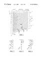
- FIG. 1depicts a heat exchange element according to the invention for a film heat exchanger
- FIG. 2depicts a cross-section through II—II in FIG. 1 of an element made up of two oppositely positioned heat exchange films, the element being pressurized
- FIG. 3depicts, in a manner corresponding to FIG. 2, a cross-section of the element, the element being unpressurized
- FIG. 4depicts, in a manner corresponding to FIG. 2, a heat exchange element made up of two heat exchange films and a support film between them,
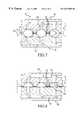
- FIG. 5depicts a top view of a mold intended for the manufacture of a heat exchange element according to FIG. 1, the mold being open,
- FIG. 6depicts the mold according to FIG. 5 as seen from the side, the mold being closed
- FIG. 7depicts on a larger scale a section of a part of a closed mold according to FIG. 6, the heat exchange films of an element being manufactured being stretched therein by means of suction,
- FIG. 8depicts, in a manner corresponding to FIG. 7, the bonding of a heat exchange film and a support film and the stretching of the heat exchange film between two mold pieces equipped with suction ducts, as part of the manufacture of a heat exchange element according to the invention, provided with support films,
- FIG. 9depicts the bonding of two heat exchange films and a support film to be positioned between them, between a pair of suction rolls, as part of the manufacturing process of a heat exchange element according to the invention.
- FIG. 10depicts a section, on a larger scale, of the bonding of the films according to FIG. 9 .
- An individual heat exchange element 1 according to FIG. 1 for a film heat exchangeris made up of two oppositely positioned plastic heat exchange films 2 , which attach to each other at the top and the bottom of the element and on the side which is on the left in the figure.
- the films 2are additionally bonded to each other along mutually parallel oblique bonding lines 3 , which divide the interior of the element into parallel ducts 4 extending from one side of the element to the other.
- the hot vapor to be condensedis introduced into the interior of the element from its at least partly open side 5 , which is on the right in the figure, in accordance with the arrows in the figure, and the condensate formed from the vapor in the ducts 4 leaves via the outlet opening 6 in the lower left corner of the element.
- a film heat exchanger which is used, for example, for the evaporation of a suspension or a solution or for the distillation of a liquidmay comprise a large number of vertically oriented heat exchange elements 1 positioned one against another, of which every section may be in a position reversed with respect to FIG. 1 so that the ducts 4 inside the elements will tilt alternately in opposite directions. This ensures that the liquid to be evaporated, directed between the elements 1 , is evenly distributed over the exterior surfaces of the heat exchange films 2 of the elements.
- FIG. 2is a cross-section of an element 1 bulged by the hot, pressurized vapor which is fed in, the films 2 premolded by stretching being outwardly bulged in the intervals between the bonding lines 3 and the vapor ducts 4 being at their maximum volume. The same element 1 is seen in the unpressurized state in FIG. 3 .
- the bulging leewayis provided in advance in the element and the bulging will take place evenly, without wrinkling or folding the films, so that no sharp rubbing points or tension peaks which would in practice lead to premature breaking of the films are formed in the films during pressurization.
- FIG. 4depicts another embodiment of the invention, wherein between the oppositely positioned heat exchange films 2 of the heat exchange element 1 there is bonded a support film 7 thicker than they.
- the support film 7divides the interior of the element 1 so that the element has expandable vapor ducts 4 on both sides of the support film.
- the structure and operation of the element 1correspond to that presented above.
- a support film 7it is possible to improve the capacity of the element to bear the solid matter left on its exterior surfaces during evaporation so that the height of the element can be increased.
- the heat exchange films 2can be made thinner, since the loadbearing capacity of the element is no longer dependent on them.
- reinforcement fibersfor example, in the form of a glassfiber or kevlar mat or net (not shown) integrated into the film.
- FIGS. 5-7show schematically one apparatus for the manufacture of the heat exchange element 1 according to FIGS. 1-3.
- FIG. 5shows an opened manufacturing mold 8 as seen from the top, and the closing of the mold can be seen in FIG. 6, which shows the mold 8 as seen from the side.
- the mold 8is made up of two mold pieces 10 hinged to each other at their ends 9 , which pieces can be turned against each other in order to stretch and bond the films placed between them.
- the structure of the mold pieces 10 and the stretching and bonding, between them, of the heat exchange films 2 to form a heat exchange element 1are shown in greater detail in FIG. 7 .
- the mold pieces 10are equipped with parallel, curved support surfaces 11 made of netting and extending obliquely across the mold pieces, and with heating resistors 12 between them.
- the rear sides of the support surfaces 11are connected to a vacuum duct system 13 in order to produce vacuum suction.
- the heat exchange films 2 which form the element 1and which have been placed on the mold pieces 10 while the mold 8 is open, remain between the mold pieces turned against each other and are heat sealed to each other at the bonding lines 3 formed by the heating resistors 2 .
- the vacuum suction generated in the intervals between the bonding points 3 via the duct system 13stretches the films 2 against the perforated support surfaces 11 while heat effective inside the mold 8 deforms the films so that the stretching produced in them will be permanent.
- the element 1is thus molded between the mold pieces 10 into a shape which it will have in use when the interior of the element is bulged by pressurized vapor, cf. FIG. 2 .
- the film heating required for the deformation of the heat exchange films 2may be carried out, for example, by irradiation before the closing of the mold 8 or by carrying out the entire molding process in a heating chamber. It is also possible to use hot air blown between the films 2 ; when pressurized sufficiently the hot air may promote the stretching of the films against the support surfaces 11 of the mold pieces. According to one embodiment of the invention, the stretching of the films 2 can indeed be carried by means of pressurized air blowing alone, in which case the suction duct systems 13 of the mold are unnecessary and may be omitted.
- FIG. 8relates to the manufacturing process of a heat exchange element which is made up of two heat exchange films 2 and of two support films 7 between them.
- the manufactureis carried out by first attaching each of the heat exchange films 2 separately to the support film 7 coming against it and by thereafter bonding to each other the film pairs thus obtained.
- FIG. 8depicts the first stretching and bonding step of the said process, wherein a heat exchange film 2 and a support film 7 are bonded to each other between two oppositely positioned mold pieces 10 .
- One of the mold pieces 10is equipped with curved support surfaces 11 made of netting, against which the heat exchange film 2 is stretched by means of vacuum suction generated via a duct system 13 .
- the opposite mold piece 10has support surfaces 14 , also of net sheet, and a vacuum duct system 13 , but in a manner deviating from the foregoing the support surfaces 14 are straight, in which case the vacuum suction only keeps the support film 7 in place without subjecting it to stretching.
- the mold pieces 10In the intervals between the support surfaces 11 , 14 the mold pieces 10 have heating resistors 12 for bonding the heat exchange film 2 and the support film 7 to each other along the bonding lines 3 formed by the resistors.
- the heat exchange film 2In FIG. 8, in which the mold pieces 10 are against each other, the heat exchange film 2 is stretched into its final shape, which corresponds to the bulging of the film by pressurized vapor during use, and bonded to a support film 7 which has not been subjected to deformation.
- the bonding together of the film pairs produced in accordance with FIG. 8, made up of heat exchange and support films 2 , 7 , to form a heat exchange element made up of two heat exchange films 2 and two support films 7 between themmay be carried out by bringing the film pairs, each in a separate mold piece 10 , opposite each other and by bonding the film pairs together by means of the heating resistors 12 in the mold pieces.
- the stretching and bonding step of the process of manufacturing a heat exchange element made up of two heat exchange films 2 and one support film 7 between themis carried out by directing the films 2 , 7 between two oppositely positioned suction rolls 15 . Before coming between the rolls 15 the films 2 , 7 are heated by means of heating rolls 16 and irradiators 17 . The surfaces of rolls 15 are profiled by means of metal wires 18 positioned on them in a manner corresponding to the bonding lines of the element to be manufactured, there being a permeable metal net 19 under the wires.
- the suction stretching the heat exchange films 2is effective in each roll 15 within a sector 20 separated in the area of the roll nip from the interior of the roll and within which vacuum prevails.
- the suctiondraws the heated heat exchange films 2 , while stretching them, into the recesses 21 between the metal wires 18 projecting from the surfaces of the rolls, while the thicker support film 7 remains straight between the rolls, as can be seen in FIG. 10 .
- the hot films 2 , 7are pressed and bonded to each other between the metal wires 18 projecting from the oppositely positioned rolls 15 .
- FIGS. 9 and 10for the stretching and bonding of the films 2 , 7 produces a continuous bonded film web 22 , which is thereafter cut into separate heat exchange elements 1 .
- an element according to FIG. 1the interior of which is divided by bonding into parallel ducts running obliquely across the element.
- the surfaces of the rollscan be preferably profiled to produce at one time all the seams required in the element, i.e. both the side and end seams of the element and the bonding lines delimiting the ducts in accordance with the specifications of the element, in which case the element can be obtained from the bonded web simply by being cut out along its outline.
- the various embodiments of the inventionare not limited to those presented above by way of example, but may vary within the accompanying claims.
- the bonding lines of the element and the ducts delimited by themare straight and continuous; the bonding lines may be broken and/or meandering or be made up of separate, point-like bonding points or of combinations of these bonding patterns.
- the stretching, in accordance with the invention, of the heat exchange film in the intervals between the bonding points in the element manufacturing phasewill provide a premolded heat exchange element which can be bulged without wrinkles and folds which would cause tension peaks or abrasion.
Landscapes
- Engineering & Computer Science (AREA)
- Mechanical Engineering (AREA)
- Physics & Mathematics (AREA)
- Thermal Sciences (AREA)
- General Engineering & Computer Science (AREA)
- Chemical Kinetics & Catalysis (AREA)
- Manufacturing & Machinery (AREA)
- Chemical & Material Sciences (AREA)
- Shaping By String And By Release Of Stress In Plastics And The Like (AREA)
- Heat-Exchange Devices With Radiators And Conduit Assemblies (AREA)
- Vaporization, Distillation, Condensation, Sublimation, And Cold Traps (AREA)
- Lining Or Joining Of Plastics Or The Like (AREA)
- Laminated Bodies (AREA)
- Encapsulation Of And Coatings For Semiconductor Or Solid State Devices (AREA)
- Air-Conditioning For Vehicles (AREA)
- Containers And Plastic Fillers For Packaging (AREA)
- Blow-Moulding Or Thermoforming Of Plastics Or The Like (AREA)
- Shaping Of Tube Ends By Bending Or Straightening (AREA)
- Thin Magnetic Films (AREA)
- Cameras Adapted For Combination With Other Photographic Or Optical Apparatuses (AREA)
Abstract
Description
Claims (18)
Applications Claiming Priority (3)
| Application Number | Priority Date | Filing Date | Title |
|---|---|---|---|
| FI970227AFI106983B (en) | 1997-01-20 | 1997-01-20 | Heat transfer elements in a film evaporator or distillator and process for its preparation |
| FI970227 | 1997-01-20 | ||
| PCT/FI1998/000038WO1998031529A1 (en) | 1997-01-20 | 1998-01-19 | Heat exchange element for a film heat exchanger and a method for manufacturing the same |
Publications (1)
| Publication Number | Publication Date |
|---|---|
| US6547000B1true US6547000B1 (en) | 2003-04-15 |
Family
ID=8547692
Family Applications (1)
| Application Number | Title | Priority Date | Filing Date |
|---|---|---|---|
| US09/341,855Expired - LifetimeUS6547000B1 (en) | 1997-01-20 | 1998-01-19 | Heat exchange for a film heat exchanger and a method for manufacturing the same |
Country Status (15)
| Country | Link |
|---|---|
| US (1) | US6547000B1 (en) |
| EP (1) | EP0952913B1 (en) |
| JP (1) | JP3363455B2 (en) |
| KR (1) | KR100565702B1 (en) |
| AT (1) | ATE206658T1 (en) |
| BR (1) | BR9806788A (en) |
| CA (1) | CA2278305C (en) |
| DE (1) | DE69801982T2 (en) |
| DK (1) | DK0952913T3 (en) |
| ES (1) | ES2166595T3 (en) |
| FI (1) | FI106983B (en) |
| GR (1) | GR3037020T3 (en) |
| NO (1) | NO316813B1 (en) |
| PT (1) | PT952913E (en) |
| WO (1) | WO1998031529A1 (en) |
Cited By (10)
| Publication number | Priority date | Publication date | Assignee | Title |
|---|---|---|---|---|
| US20030173064A1 (en)* | 2001-04-09 | 2003-09-18 | Tatsuhiko Ueki | Plate-type heat pipe and method for manufacturing the same |
| US20090194268A1 (en)* | 2006-08-28 | 2009-08-06 | Dantherm Air Handling A/S | Method for manufacturing a heat exchanger |
| WO2011110726A1 (en)* | 2010-03-08 | 2011-09-15 | Chemitec Consulting Oy | Heat exchange element, a heat exchanger comprising the elements, and an equipment for the manufacture of the elements |
| US20120006519A1 (en)* | 2005-12-16 | 2012-01-12 | Haul-All Equipment Ltd. | Vented, gas-fired air heater |
| US8460554B2 (en) | 2009-08-24 | 2013-06-11 | Oasys Water, Inc. | Forward osmosis membranes |
| US9156006B2 (en) | 2009-12-03 | 2015-10-13 | Yale University | High flux thin-film composite forward osmosis and pressure-retarded osmosis membranes |
| US9186627B2 (en) | 2009-08-24 | 2015-11-17 | Oasys Water, Inc. | Thin film composite heat exchangers |
| US11229855B2 (en) | 2014-03-21 | 2022-01-25 | Life Technologies Corporation | Condenser systems for processing a fluid |
| US11492582B2 (en) | 2010-02-22 | 2022-11-08 | Life Technologies Corporation | Heat exchanger system with flexible bag |
| US11554335B2 (en) | 2014-03-21 | 2023-01-17 | Life Technologies Corporation | Methods for gas filteration in fluid processing systems |
Families Citing this family (13)
| Publication number | Priority date | Publication date | Assignee | Title |
|---|---|---|---|---|
| US8073695B1 (en) | 1992-12-09 | 2011-12-06 | Adrea, LLC | Electronic book with voice emulation features |
| US8095949B1 (en) | 1993-12-02 | 2012-01-10 | Adrea, LLC | Electronic book with restricted access features |
| HK1050576A1 (en) | 1999-11-17 | 2003-06-27 | Discovery Communications, Inc. | Electronic book having electronic commerce features |
| IT1311176B1 (en)* | 1999-12-31 | 2002-03-04 | Unifill Internat A G | CONTAINER FORMING SYSTEM FOR INJECTION OF A FLUIDOFORMER BETWEEN PARTS OF SHEET MATERIAL |
| FI111189B (en) | 2000-08-04 | 2003-06-13 | Hadwaco Tech Oy | Heat exchanger for heat transfer between gas streams |
| DE102008019828A1 (en) | 2008-04-19 | 2009-10-29 | Solarnext Ag | Foil heat-exchanger for use as e.g. evaporator during fruit juice concentration process, has coupling elements that are designed such that heat exchange medium predominantly flows transverse to grooves between foils to coupling elements |
| DE102008019829A1 (en) | 2008-04-19 | 2009-10-22 | Solarnext Ag | Mass transport between two fluids, for dehumidifying air in an air conditioning system, uses a membrane absorber formed by permeable and impermeable films |
| AT12048U1 (en) | 2010-03-23 | 2011-09-15 | Stefan Ing Petters | DEVICE FOR TRANSFERRING HEAT |
| FR2982016A1 (en)* | 2011-10-28 | 2013-05-03 | Tmw | GRAVITY FLOW LIQUID SPREADING MEDIUM, SPEEDING SYSTEM AND EVAPORATION COLUMN COMPRISING SUCH A SUPPORT |
| DE102015217780A1 (en)* | 2015-09-17 | 2017-03-23 | Robert Bosch Gmbh | Method for producing a cooling device for cooling batteries |
| DE102018206768A1 (en)* | 2018-05-02 | 2019-11-07 | Continental Teves Ag & Co. Ohg | Cooling system and motor vehicle |
| CN110508015A (en)* | 2019-08-12 | 2019-11-29 | 佛山市欧若拉生物科技有限公司 | A kind of plant material evaporation extraction cooling device |
| JP7482501B2 (en)* | 2020-04-09 | 2024-05-14 | 株式会社総合設備コンサルタント | Falling film heat exchanger |
Citations (19)
| Publication number | Priority date | Publication date | Assignee | Title |
|---|---|---|---|---|
| US3036369A (en)* | 1955-06-29 | 1962-05-29 | Revere Copper & Brass Inc | Method of making fluid conducting elements |
| DE1259362B (en) | 1959-06-29 | 1968-01-25 | Joachim Beushausen | Heat exchanger with plate-like heat exchange walls made of easily flexible plastic films |
| US3648768A (en)* | 1969-05-22 | 1972-03-14 | Scholl Dr Ing Gunter | Heat-exchanger components |
| US4017351A (en) | 1975-12-24 | 1977-04-12 | Minnesota Mining And Manufacturing Company | System and device for inflating and sealing air inflated cushioning material |
| US4111659A (en) | 1974-09-25 | 1978-09-05 | Graeme L. Hammond | Mass and heat transfer exchange apparatus |
| EP0037802A2 (en) | 1980-03-17 | 1981-10-14 | LINDHOLM, Alfons Seth Mikael | Tubular electrode plate for lead accumulators |
| FR2492312A1 (en) | 1980-10-17 | 1982-04-23 | Teraoka Syoichi | METHOD AND APPARATUS FOR PRODUCING A HOLLOW MOLDED OBJECT OF SYNTHETIC THERMOPLASTIC RESIN |
| US4351797A (en) | 1978-11-08 | 1982-09-28 | Bellhouse Brian John | Transfer membrane assembly |
| US4411310A (en) | 1978-04-07 | 1983-10-25 | The Boeing Company | Heat exchange apparatus having thin film flexible sheets |
| US4471759A (en) | 1981-04-28 | 1984-09-18 | B. Shawn Buckley | Method of forming a solar collector or hot water storage tank and solar water heating apparatus using same |
| US4562630A (en)* | 1980-10-21 | 1986-01-07 | Gunnar Larsson | Method for the manufacture of heat exchanger elements |
| US4585523A (en) | 1984-02-27 | 1986-04-29 | Giddings Edward H | Vapor compression distillation apparatus |
| EP0286399A1 (en) | 1987-04-08 | 1988-10-12 | Du Pont Canada Inc. | Heat exchanger fabricated from polymer compositions |
| WO1991004451A1 (en) | 1989-09-15 | 1991-04-04 | Sten Zeilon | Thin film gas heat exchanger |
| US5411079A (en)* | 1992-10-06 | 1995-05-02 | Sanden Corporation | Heat exchanger and method for manufacturing the same |
| US5505256A (en)* | 1991-02-19 | 1996-04-09 | Rolls-Royce Plc | Heat exchangers and methods of manufacture thereof |
| US5634269A (en) | 1994-09-09 | 1997-06-03 | Gas Research Institute | Thin plastic-film heat exchanger for absorption chillers |
| US6050330A (en)* | 1996-05-24 | 2000-04-18 | Sollac | Metal tank |
| EP1465564A1 (en) | 2001-11-05 | 2004-10-13 | Wieslaw Brojek | Method and the device for cryogenic therapy applied on the whole body of the patient |
Family Cites Families (2)
| Publication number | Priority date | Publication date | Assignee | Title |
|---|---|---|---|---|
| GB1465564A (en)* | 1974-04-24 | 1977-02-23 | Du Pont | Laminated article |
| GB8808944D0 (en)* | 1988-04-15 | 1988-05-18 | Du Pont Canada | Method for manufacture of thermoplastic panel heat exchangers |
- 1997
- 1997-01-20FIFI970227Apatent/FI106983B/ennot_activeIP Right Cessation
- 1998
- 1998-01-19BRBR9806788-5Apatent/BR9806788A/ennot_activeApplication Discontinuation
- 1998-01-19WOPCT/FI1998/000038patent/WO1998031529A1/enactiveIP Right Grant
- 1998-01-19KRKR1019997006527Apatent/KR100565702B1/ennot_activeExpired - Fee Related
- 1998-01-19DKDK98900870Tpatent/DK0952913T3/enactive
- 1998-01-19PTPT98900870Tpatent/PT952913E/enunknown
- 1998-01-19EPEP98900870Apatent/EP0952913B1/ennot_activeExpired - Lifetime
- 1998-01-19ESES98900870Tpatent/ES2166595T3/ennot_activeExpired - Lifetime
- 1998-01-19ATAT98900870Tpatent/ATE206658T1/ennot_activeIP Right Cessation
- 1998-01-19USUS09/341,855patent/US6547000B1/ennot_activeExpired - Lifetime
- 1998-01-19DEDE69801982Tpatent/DE69801982T2/ennot_activeExpired - Fee Related
- 1998-01-19CACA002278305Apatent/CA2278305C/ennot_activeExpired - Fee Related
- 1998-01-19JPJP53138598Apatent/JP3363455B2/ennot_activeExpired - Fee Related
- 1999
- 1999-07-14NONO19993470Apatent/NO316813B1/ennot_activeIP Right Cessation
- 2001
- 2001-10-25GRGR20010401891Tpatent/GR3037020T3/ennot_activeIP Right Cessation
Patent Citations (20)
| Publication number | Priority date | Publication date | Assignee | Title |
|---|---|---|---|---|
| US3036369A (en)* | 1955-06-29 | 1962-05-29 | Revere Copper & Brass Inc | Method of making fluid conducting elements |
| DE1259362B (en) | 1959-06-29 | 1968-01-25 | Joachim Beushausen | Heat exchanger with plate-like heat exchange walls made of easily flexible plastic films |
| US3648768A (en)* | 1969-05-22 | 1972-03-14 | Scholl Dr Ing Gunter | Heat-exchanger components |
| US3648768B1 (en)* | 1969-05-22 | 1983-10-18 | ||
| US4111659A (en) | 1974-09-25 | 1978-09-05 | Graeme L. Hammond | Mass and heat transfer exchange apparatus |
| US4017351A (en) | 1975-12-24 | 1977-04-12 | Minnesota Mining And Manufacturing Company | System and device for inflating and sealing air inflated cushioning material |
| US4411310A (en) | 1978-04-07 | 1983-10-25 | The Boeing Company | Heat exchange apparatus having thin film flexible sheets |
| US4351797A (en) | 1978-11-08 | 1982-09-28 | Bellhouse Brian John | Transfer membrane assembly |
| EP0037802A2 (en) | 1980-03-17 | 1981-10-14 | LINDHOLM, Alfons Seth Mikael | Tubular electrode plate for lead accumulators |
| FR2492312A1 (en) | 1980-10-17 | 1982-04-23 | Teraoka Syoichi | METHOD AND APPARATUS FOR PRODUCING A HOLLOW MOLDED OBJECT OF SYNTHETIC THERMOPLASTIC RESIN |
| US4562630A (en)* | 1980-10-21 | 1986-01-07 | Gunnar Larsson | Method for the manufacture of heat exchanger elements |
| US4471759A (en) | 1981-04-28 | 1984-09-18 | B. Shawn Buckley | Method of forming a solar collector or hot water storage tank and solar water heating apparatus using same |
| US4585523A (en) | 1984-02-27 | 1986-04-29 | Giddings Edward H | Vapor compression distillation apparatus |
| EP0286399A1 (en) | 1987-04-08 | 1988-10-12 | Du Pont Canada Inc. | Heat exchanger fabricated from polymer compositions |
| WO1991004451A1 (en) | 1989-09-15 | 1991-04-04 | Sten Zeilon | Thin film gas heat exchanger |
| US5505256A (en)* | 1991-02-19 | 1996-04-09 | Rolls-Royce Plc | Heat exchangers and methods of manufacture thereof |
| US5411079A (en)* | 1992-10-06 | 1995-05-02 | Sanden Corporation | Heat exchanger and method for manufacturing the same |
| US5634269A (en) | 1994-09-09 | 1997-06-03 | Gas Research Institute | Thin plastic-film heat exchanger for absorption chillers |
| US6050330A (en)* | 1996-05-24 | 2000-04-18 | Sollac | Metal tank |
| EP1465564A1 (en) | 2001-11-05 | 2004-10-13 | Wieslaw Brojek | Method and the device for cryogenic therapy applied on the whole body of the patient |
Cited By (21)
| Publication number | Priority date | Publication date | Assignee | Title |
|---|---|---|---|---|
| US6871701B2 (en)* | 2001-04-09 | 2005-03-29 | The Furukawa Electric Co., Ltd. | Plate-type heat pipe and method for manufacturing the same |
| US20050126759A1 (en)* | 2001-04-09 | 2005-06-16 | The Furukawa Electric Co., Ltd. | Plate-type heat pipe and method for manufacturing the same |
| US20030173064A1 (en)* | 2001-04-09 | 2003-09-18 | Tatsuhiko Ueki | Plate-type heat pipe and method for manufacturing the same |
| US8376733B2 (en) | 2005-12-16 | 2013-02-19 | Haul-All Equipment Ltd. | Burner for heater |
| US20120006519A1 (en)* | 2005-12-16 | 2012-01-12 | Haul-All Equipment Ltd. | Vented, gas-fired air heater |
| US20090194268A1 (en)* | 2006-08-28 | 2009-08-06 | Dantherm Air Handling A/S | Method for manufacturing a heat exchanger |
| US9186627B2 (en) | 2009-08-24 | 2015-11-17 | Oasys Water, Inc. | Thin film composite heat exchangers |
| US9463422B2 (en) | 2009-08-24 | 2016-10-11 | Oasys Water, Inc. | Forward osmosis membranes |
| US8460554B2 (en) | 2009-08-24 | 2013-06-11 | Oasys Water, Inc. | Forward osmosis membranes |
| US9156006B2 (en) | 2009-12-03 | 2015-10-13 | Yale University | High flux thin-film composite forward osmosis and pressure-retarded osmosis membranes |
| US12012579B2 (en) | 2010-02-22 | 2024-06-18 | Life Technologies Corporation | Heat exchanger system with flexible bag |
| US11492582B2 (en) | 2010-02-22 | 2022-11-08 | Life Technologies Corporation | Heat exchanger system with flexible bag |
| KR101700846B1 (en) | 2010-03-08 | 2017-01-31 | 아빈드 악셀 리미티드 | Heat exchange element, a heat exchanger comprising the elements, and an equipment for the manufacture of the elements |
| KR20130057422A (en)* | 2010-03-08 | 2013-05-31 | 아빈드 악셀 리미티드 | Heat exchange element, a heat exchanger comprising the elements, and an equipment for the manufacture of the elements |
| US9372033B2 (en) | 2010-03-08 | 2016-06-21 | Arvind Accel Limited | Heat exchange element, a heat exchanger comprising the elements, and an equipment for the manufacture of the elements |
| WO2011110726A1 (en)* | 2010-03-08 | 2011-09-15 | Chemitec Consulting Oy | Heat exchange element, a heat exchanger comprising the elements, and an equipment for the manufacture of the elements |
| US11229855B2 (en) | 2014-03-21 | 2022-01-25 | Life Technologies Corporation | Condenser systems for processing a fluid |
| US11554335B2 (en) | 2014-03-21 | 2023-01-17 | Life Technologies Corporation | Methods for gas filteration in fluid processing systems |
| US11717768B2 (en) | 2014-03-21 | 2023-08-08 | Life Technologies Corporation | Condenser bag for processing a fluid |
| US12076681B2 (en) | 2014-03-21 | 2024-09-03 | Life Technologies Corporation | Methods for gas filtration in fluid processing systems |
| US12285713B2 (en) | 2014-03-21 | 2025-04-29 | Life Technologies Corporation | Condenser bag for processing a fluid |
Also Published As
| Publication number | Publication date |
|---|---|
| KR100565702B1 (en) | 2006-03-29 |
| WO1998031529A1 (en) | 1998-07-23 |
| JP3363455B2 (en) | 2003-01-08 |
| FI970227A0 (en) | 1997-01-20 |
| DE69801982D1 (en) | 2001-11-15 |
| CA2278305C (en) | 2006-10-17 |
| FI970227L (en) | 1998-07-21 |
| JP2001502044A (en) | 2001-02-13 |
| EP0952913A1 (en) | 1999-11-03 |
| NO993470D0 (en) | 1999-07-14 |
| DK0952913T3 (en) | 2001-11-19 |
| CA2278305A1 (en) | 1998-07-23 |
| GR3037020T3 (en) | 2002-01-31 |
| AU717078B2 (en) | 2000-03-16 |
| FI106983B (en) | 2001-05-15 |
| AU5665798A (en) | 1998-08-07 |
| DE69801982T2 (en) | 2002-04-04 |
| NO993470L (en) | 1999-09-20 |
| ES2166595T3 (en) | 2002-04-16 |
| EP0952913B1 (en) | 2001-10-10 |
| KR20000070297A (en) | 2000-11-25 |
| BR9806788A (en) | 2000-05-16 |
| ATE206658T1 (en) | 2001-10-15 |
| PT952913E (en) | 2002-01-30 |
| NO316813B1 (en) | 2004-05-18 |
Similar Documents
| Publication | Publication Date | Title |
|---|---|---|
| US6547000B1 (en) | Heat exchange for a film heat exchanger and a method for manufacturing the same | |
| US5089202A (en) | Method for the production of a filter cartridge | |
| CA2687549C (en) | Structured forming fabric | |
| CN101367022B (en) | Filter element | |
| JP4069235B2 (en) | Method for producing a compressed fabric by spirally attaching a top laminate layer with a thermoactive adhesive | |
| JP3511227B2 (en) | Paper machine fabric having a pair of different machine direction yarns woven together | |
| CN107257910B (en) | Total heat exchanger element, total heat exchanger comprising such an element and method for producing same | |
| EA039188B1 (en) | Enthalpy exchanger element, enthalpy exchanger comprising such elements and method for production thereof | |
| AU717078C (en) | Heat exchange element for a film heat exchanger and a method for manufacturing the same | |
| US6569290B2 (en) | Bi-component molded modular link and a fabric made from a plurality thereof | |
| GB2168643A (en) | Shaping sheet material | |
| US6758261B2 (en) | Apparatus for heat transfer between gas flows | |
| JP2548468B2 (en) | Gas bags for restraints in automobiles | |
| JP2001503690A (en) | Apparatus and method for manufacturing flexible heat exchanger | |
| JP3639090B2 (en) | Pleated fabric | |
| JP2747676B2 (en) | How to fold curtains | |
| KR102689025B1 (en) | A flat-type air filter without wrinkle structure, and system and method for manufacturing of the air filter | |
| JP4925655B2 (en) | Connecting hood for vehicle | |
| CA2262397C (en) | Method and apparatus for drying a moist web | |
| US20220259804A1 (en) | Wound clothing | |
| JP3599398B2 (en) | Parts press equipment in press machine | |
| GB2602126A (en) | A structural panel and method and apparatus for manufacture | |
| JPH07148849A (en) | Production of fiber composite sheet | |
| TW201205008A (en) | Air-conditioner filter manufacturing method and structure thereof |
Legal Events
| Date | Code | Title | Description |
|---|---|---|---|
| AS | Assignment | Owner name:HADWACO LTD. OY, FINLAND Free format text:ASSIGNMENT OF ASSIGNORS INTEREST;ASSIGNORS:RANTALA, REIJO (DECEASED) VIRPI RANTALA FOR REIJO RANTALA;RANTALA, MERITA FOR REIJO RANTALA;RANTALA, MARKO FOR REIJO RANTALA;AND OTHERS;REEL/FRAME:010266/0398;SIGNING DATES FROM 19990830 TO 19990913 | |
| STCF | Information on status: patent grant | Free format text:PATENTED CASE | |
| AS | Assignment | Owner name:HADWACO TECHNOLOGIES OY, FINLAND Free format text:CHANGE OF NAME;ASSIGNOR:OY CASPARADO AB;REEL/FRAME:014499/0426 Effective date:20030324 Owner name:OY CASPARADO AB, FINLAND Free format text:ASSIGNMENT OF ASSIGNORS INTEREST;ASSIGNOR:HADWACO LTD. OY;REEL/FRAME:014499/0049 Effective date:20030214 | |
| AS | Assignment | Owner name:EBARA CORPORATION, JAPAN Free format text:ASSIGNMENT OF ASSIGNORS INTEREST;ASSIGNOR:HADWACO TECHNOLOGIES OY;REEL/FRAME:018148/0767 Effective date:20060510 | |
| FPAY | Fee payment | Year of fee payment:4 | |
| AS | Assignment | Owner name:EBARA ENGINEERING SERVICE CO., LTD.,JAPAN Free format text:ASSIGNMENT OF ASSIGNORS INTEREST;ASSIGNOR:EBARA CORPORATION;REEL/FRAME:023985/0462 Effective date:20100223 | |
| FPAY | Fee payment | Year of fee payment:8 | |
| REMI | Maintenance fee reminder mailed | ||
| FPAY | Fee payment | Year of fee payment:12 | |
| SULP | Surcharge for late payment | Year of fee payment:11 |