US6546494B1 - Providing power to a device over a network transmission medium - Google Patents
Providing power to a device over a network transmission mediumDownload PDFInfo
- Publication number
- US6546494B1 US6546494B1US09/413,141US41314199AUS6546494B1US 6546494 B1US6546494 B1US 6546494B1US 41314199 AUS41314199 AUS 41314199AUS 6546494 B1US6546494 B1US 6546494B1
- Authority
- US
- United States
- Prior art keywords
- power
- transmission medium
- network transmission
- over
- controller
- Prior art date
- Legal status (The legal status is an assumption and is not a legal conclusion. Google has not performed a legal analysis and makes no representation as to the accuracy of the status listed.)
- Expired - Lifetime
Links
Images


Classifications
- H—ELECTRICITY
- H04—ELECTRIC COMMUNICATION TECHNIQUE
- H04B—TRANSMISSION
- H04B3/00—Line transmission systems
- H04B3/54—Systems for transmission via power distribution lines
- H—ELECTRICITY
- H04—ELECTRIC COMMUNICATION TECHNIQUE
- H04B—TRANSMISSION
- H04B2203/00—Indexing scheme relating to line transmission systems
- H04B2203/54—Aspects of powerline communications not already covered by H04B3/54 and its subgroups
- H04B2203/5429—Applications for powerline communications
- H04B2203/5437—Wired telephone
- H—ELECTRICITY
- H04—ELECTRIC COMMUNICATION TECHNIQUE
- H04B—TRANSMISSION
- H04B2203/00—Indexing scheme relating to line transmission systems
- H04B2203/54—Aspects of powerline communications not already covered by H04B3/54 and its subgroups
- H04B2203/5429—Applications for powerline communications
- H04B2203/5445—Local network
- H—ELECTRICITY
- H04—ELECTRIC COMMUNICATION TECHNIQUE
- H04B—TRANSMISSION
- H04B2203/00—Indexing scheme relating to line transmission systems
- H04B2203/54—Aspects of powerline communications not already covered by H04B3/54 and its subgroups
- H04B2203/5429—Applications for powerline communications
- H04B2203/5458—Monitor sensor; Alarm systems
- H—ELECTRICITY
- H04—ELECTRIC COMMUNICATION TECHNIQUE
- H04B—TRANSMISSION
- H04B2203/00—Indexing scheme relating to line transmission systems
- H04B2203/54—Aspects of powerline communications not already covered by H04B3/54 and its subgroups
- H04B2203/5462—Systems for power line communications
- H04B2203/5495—Systems for power line communications having measurements and testing channel
Definitions
- This inventionrelates to providing power to a device over a network transmission medium.
- Network devicessuch as personal computers (“PCs”) and IP (“Internet Protocol”) telephones, traditionally received power from wall outlets. Such devices have additional wiring to connect them to the wall outlets. In some configurations, this can be inefficient, particularly for devices that are connected to networks via transmission media, such as Ethernet, that are capable of transmitting power with little or no adverse effect on network data. Systems were therefore developed for providing power to a device over Ethernet wiring.
- the inventionfeatures a method which determines if a device can accept power over a network transmission medium, and which provides power to the device over the network transmission medium if it is determined that the device can accept power over the network transmission medium. By determining whether the device can accept power before applying the power, the invention reduces damage caused by improper application of power.
- Determining if the device can accept power over the network transmission mediumincludes sensing if there is an overcurrent condition in the device and/or sensing if the device is receiving power from another source.
- the methoddetermines if the device can accept power by supplying an initial power pulse to the device over the network transmission medium, determining whether the device can handle additional power based on the initial power pulse, and supplying a test power pulse to the device over the network transmission medium if the device can handle the additional power.
- the initial power pulsemay be shorter than the test power pulse.
- the methoddetermines if the device can handle the additional power by sensing an amount of current that is absorbed by the device in response to the initial power pulse, and determining whether the device can handle the additional power based on the amount of current that is absorbed by the device.
- the amount of current that is absorbed by the deviceis sensed using a resistor that is coupled in series with the network transmission medium.
- the methodmay include receiving an indication, in response to the test power pulse, that the device can accept power over the network transmission medium.
- the indicationmay comprise a link status bit that is transmitted from the device.
- the methodmay store data indicating whether power is being supplied to the device.
- the power provided to the devicemay be controlled by a remote network device.
- the network transmission mediummay comprise an Ethernet line.
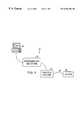
- FIG. 1is a view of a network system.
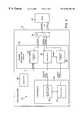
- FIG. 2is a block diagram of circuitry for providing power over a network transmission medium in the system.
- FIG. 3is a circuit diagram showing a specific embodiment of the circuitry of FIG. 2 .
- FIG. 4is a close-up view of a power regulation circuit from the circuit diagram of FIG. 3 .
- FIG. 5is a flowchart showing a process for providing power over the network transmission medium.
- Network system 10includes devices 12 , 14 and 16 , network transmission medium 18 , and intermediary network 20 .
- Device 12is a PC, or other processing device, that is capable of receiving, processing and transmitting data packets via intermediary network 20 .
- Intermediary network 20may be any type of network, such as the Internet, a local area network (“LAN”) , a wide area network (“WAN”) , or an asynchronous transfer mode (“ATM”) network.
- Device 14links device 16 to intermediary network 20 .
- Devices 14 and 16are connected by network transmission medium 18 , such as Ethernet wiring, and are generally part of the same LAN (though this is not a requirement).
- Device 16may be any type of network device, such as a PC, a computer peripheral, an IP telephone, and a small appliance.
- Device 14is typically a switch or a router; however, other network devices may also be used.
- device 14supplies power to device 16 over network transmission medium 18 .
- Device 14receives AC (“Alternating Current”) power from a power source which is either internal to, or external to, device 14 (for example, the power source may be in a “wiring closet” for device 14 ).
- a rectifier(not shown) converts the AC power to, e.g., +48 V (“Volts”) of DC (“Direct Current”) power, and provides the DC power to circuitry in device 14 .
- the circuitrysupplies this power to device 16 over network transmission medium 18 .
- Circuitry 22includes a controller 24 and a power regulation circuit 26 .
- a power supply 28Connected to power regulation circuit 26 are a power supply 28 , which provides the +48 V noted above, and a port 30 , such as a connector, which connects to network transmission medium 18 .
- power supply 28is a Jini-enabled, network-attached modular power source. Jini is a Java-based distributed computing environment from Sun Microsystems®, in which devices can be plugged into a network and automatically offer their services, and make use of services, on the network. Power regulation circuit 26 is used to regulate the supply of power from power supply 28 to device 16 .
- Power regulation circuit 26includes protection circuit 32 , sense circuit 34 , and power gate circuit 36 .
- Protection circuit 32is a fuse or suppressor circuit which protects wiring and circuitry in networked devices in case power is inadvertently applied.
- Poweris routed from power supply 28 to power gate circuit 36 through the same port 30 that connects to network transmission medium 18 .
- Power gate circuit 36comprises a switch which closes in response to signals from controller 24 to provide power from power supply 28 to port 30 .
- Sense circuit 34monitors the amount of current that device 16 absorbs in response to a power pulse, and provides this information to controller 24 . Controller 24 uses this information to determine whether device 16 can handle continuous power over network transmission medium 18 .
- Controller 24includes a port select and sample circuit 38 and a control circuit 40 . These circuits may be implemented using a programmed gate array in combination with a CPU (“Control Processing Unit”), such as a microprocessor. Alternatively, controller 24 may be implemented using an ASIC (“Application-Specific Integrated Circuit”). In any case, control circuit 24 receives signals provided by sense circuit 34 and determines, based on these signals, whether and when to open/close the switch of power gate circuit 36 . Port select and sample circuit 38 is used to select different ports, over which power is to be supplied. For example, a single circuit board may include several power regulation circuits 26 (protection circuit 32 , sense circuit 34 , and power gate circuit 36 ) in order to provide power to network transmission media over several different ports. Port select and sample circuit 38 receives information from each sense circuit 34 on such a board, and control circuit 40 uses that information to determine whether power can be supplied over each port.
- a single circuit boardmay include several power regulation circuits 26 (protection circuit 32 , sense circuit 34 , and
- FIG. 3shows one implementation of circuitry 22 .
- FIG. 3shows a circuit board 42 having a controller 44 and eight power regulation circuits 46 a to 46 h for providing power to network transmission media over eight ports (via connectors 48 , 50 , 52 and 54 ).
- FIG. 4a close-up view of any of the power regulation circuits of FIG. 3 (e.g., 46 a ) is shown.
- Power regulation circuit 46 ais identical to the other power regulation circuits on board 42 .
- Fuse 60comprises the protection circuit 32 of FIG. 2
- sense resistor 62 and operational amplifier 64comprise the sense circuit 34
- transistor 66comprises the power gate circuit 36 .
- Transistor 66is a source-ballasted N-channel VFET; and fuse 60 is an auto-resetting chemical fuse constituting dead-man protection.
- Sense resistor 62is on the order of 0.1 ohms (“ ⁇ ”) and it is coupled in series with network transmission medium 18 (and thus device 16 ) relative to transistor 66 .
- Power 68is routed from power supply 68 to transistor 66 through connector 48 (via lines 69 and 70 ), such that, when transistor 66 is gated (i.e., the switch defined by transistor 66 is closed), power is supplied from line 70 , through sense resistor 62 , transistor 66 , and line 71 to network transmission medium 18 .
- controller 44includes a programmed gate array 72 , a clock oscillator 74 to clock signals to/from gate array 72 , and a multiplexer 76 to provide signals to/from the power regulation circuits of FIG. 3 .
- Process 78is shown for controlling the circuitry shown in FIGS. 2, 3 and 4 .
- Process 78is implemented, in part, by computer program(s) executing on controller 24 in conjunction with the circuitry in one (or more) power regulation circuits.
- Process 78determines 80 if a networked device 16 is configured to accept power via network transmission medium 18 (and thus can withstand the application of such power). Determining 80 begins by supplying 80 a an initial power pulse to device 16 over network transmission medium 18 . Power is supplied over wires which do not carry data, such as those connected to pins seven and eight of a standard Ethernet connector. To supply this initial power pulse, controller 24 issues a signal to power gate circuit 36 , which causes the switch of power gate circuit 36 to close for a period of time corresponding to the initial power pulse. For example, in circuit 46 a (FIG. 4 ), a signal 43 from controller 44 (passed through operational amplifier 64 ), causes the switch defined by transistor 66 to close and provide power from line 70 to network transmission medium 18 (via sense resistor 62 , line 71 , and connector 48 ).
- the duration of the initial power pulseshould be long enough to ascertain whether device 16 can handle additional power, yet short enough so as not to cause damage to circuitry in device 16 .
- An initial power pulse on the order of 100 microseconds (“ ⁇ S”)satisfies both criteria for most devices.
- controller 24issues a signal which opens the switch of power gate circuit 36 (or, in the embodiment of FIG. 4, transistor 66 ).
- process 78determines 80 b if device 16 can handle additional power based on the initial power pulse.
- sense circuit 34measures the amount of current that is absorbed by device 16 in response to the initial power pulse.
- operational amplifier 64measures an amount of differential voltage across sense resistor 62 (which, as defined in Ohm's law, corresponds to an amount of current that device 16 is drawing), and outputs a “voltage level” signal to the controller that is indicative of this differential voltage.
- the controllersenses 80 b 1 the amount of current that is absorbed by device 16 based on this voltage level signal.
- Controller 24determines 80 b 2 if device 16 can handle additional power based on the amount of current that device 16 absorbs. For example, if device 16 draws an inordinate amount of current (more than a preset amount), then controller 24 may determine that device 16 is unable to handle additional power. Controller 24 will not allow additional power to be supplied to device 16 in this case.
- Controller 24determines that there is a short circuit in device 16 if device 16 draws an extremely large amount of current (an overcurrent condition) from power supply 28 (resulting in a relatively high voltage across resistor 62 in the embodiment of FIG. 4 ). Controller 24 determines if device 16 is receiving power from another source by measuring the polarity of the voltage across sense circuit 34 produced when the initial power pulse is supplied (in FIG. 4, operational amplifier 64 measures the polarity of the voltage across sense resistor 62 ). A negative polarity, relative to the voltage produced when current is provided from power supply 28 , indicates that device 16 is receiving power from another source.
- controller 24determines 80 b 2 that device 16 can handle additional power
- controller 24issues a signal which causes a test power pulse to be supplied 80 c to device 16 over network transmission medium 18 .
- the test power pulseis longer in duration than the initial power pulse. For example, it may be on the order of seconds.
- the test power pulseis supplied in the same manner as the initial power pulse. The only difference is the duration during which the switch defined by power gate circuit 36 (transistor 66 ) is closed to provide power.
- controller 24waits 80 d for an indication from device 16 that device 16 can receive continuous power over network transmission medium 18 .
- the indicationis a link status bit (“LSB”) that is received from device 16 over network transmission medium 18 ; however, any other indication may be used.
- An LSBis used because many network devices are pre-configured to provide an LSB in response to a power pulse of a predetermined duration.
- Process 78may store 84 data in a memory (not shown) that is internal to, or external to, switch 14 .
- This dataindicates the status of power to device 16 ; for example, that device 16 is receiving power over network transmission medium 18 , is not receiving power, is receiving power from another source, or is suspected of having a short circuit.
- This datamay be used to control transmission of power.
- a computermay be interfaced to the controller in switch 14 .
- the computermay be internal to switch 14 or it may be an external device.
- the computermay be a remote network device, such as PC 12 .
- the computerexecutes software for controlling the supply of power via circuitry 22 (or 42 ).
- the computermay instruct controller 42 to provide power to network transmission medium 18 over a particular port regardless of what type of device is connected to that port.
- the computercan examine data stored in the memory (indicating, for example, that power is being supplied to a device via a port 30 ). Based on this data, the computer can turn off power to a device, turn power to the device on and off at different times (for example, power-off the device at night), or otherwise control power to the device.
- the computercan override decisions of controller 24 / 42 .
- Process 78may be executed for each of the eight power regulation circuits 46 a to 46 h shown in FIG. 3 .
- gate array 72 and multiplexer 76are used to select one of the power regulation circuits for which processing is performed.
- the power regulation circuitsmay be selected in sequence, or otherwise.
- the inventionis not limited to the circuit configurations shown in FIGS. 2, 3 and 4 .
- Other circuitrycan be used.
- different circuit componentscan be used in place of those shown in the FIGs.
- the inventioncan be used to supply different amounts of power to different network transmission media (and thus to different devices via different ports). For example, rather than supplying +48 V DC from each of the eight power regulation circuits shown in FIG. 3, different amounts of power may be supplied from each circuit.
- the powermay be supplied from different power supplies or “step-down” circuitry may be employed to reduce the amount of power. Power may supplied over network transmission media other than Ethernet.
Landscapes
- Engineering & Computer Science (AREA)
- Power Engineering (AREA)
- Computer Networks & Wireless Communication (AREA)
- Signal Processing (AREA)
- Small-Scale Networks (AREA)
- Power Sources (AREA)
- Dc Digital Transmission (AREA)
- Transmitters (AREA)
Abstract
Description
Claims (37)
Priority Applications (4)
| Application Number | Priority Date | Filing Date | Title |
|---|---|---|---|
| US09/413,141US6546494B1 (en) | 1999-10-06 | 1999-10-06 | Providing power to a device over a network transmission medium |
| EP00650136AEP1094617A3 (en) | 1999-10-06 | 2000-09-28 | Method and apparatus for providing power to a device over a network transmission medium |
| CA2322145ACA2322145C (en) | 1999-10-06 | 2000-10-04 | Providing power to a device over a network transmission medium |
| US10/410,513US20040025066A1 (en) | 1999-10-06 | 2003-04-08 | Providing power to a device over a network transmission medium |
Applications Claiming Priority (1)
| Application Number | Priority Date | Filing Date | Title |
|---|---|---|---|
| US09/413,141US6546494B1 (en) | 1999-10-06 | 1999-10-06 | Providing power to a device over a network transmission medium |
Related Child Applications (1)
| Application Number | Title | Priority Date | Filing Date |
|---|---|---|---|
| US10/410,513ContinuationUS20040025066A1 (en) | 1999-10-06 | 2003-04-08 | Providing power to a device over a network transmission medium |
Publications (1)
| Publication Number | Publication Date |
|---|---|
| US6546494B1true US6546494B1 (en) | 2003-04-08 |
Family
ID=23636019
Family Applications (2)
| Application Number | Title | Priority Date | Filing Date |
|---|---|---|---|
| US09/413,141Expired - LifetimeUS6546494B1 (en) | 1999-10-06 | 1999-10-06 | Providing power to a device over a network transmission medium |
| US10/410,513AbandonedUS20040025066A1 (en) | 1999-10-06 | 2003-04-08 | Providing power to a device over a network transmission medium |
Family Applications After (1)
| Application Number | Title | Priority Date | Filing Date |
|---|---|---|---|
| US10/410,513AbandonedUS20040025066A1 (en) | 1999-10-06 | 2003-04-08 | Providing power to a device over a network transmission medium |
Country Status (3)
| Country | Link |
|---|---|
| US (2) | US6546494B1 (en) |
| EP (1) | EP1094617A3 (en) |
| CA (1) | CA2322145C (en) |
Cited By (40)
| Publication number | Priority date | Publication date | Assignee | Title |
|---|---|---|---|---|
| US20020119097A1 (en)* | 2001-01-26 | 2002-08-29 | Gale Nicholas W. | Methods of imaging and targeting vasculature |
| US20030051177A1 (en)* | 2001-09-12 | 2003-03-13 | Kwanghoi Koo | Method and apparatus for system power control through sensing peripheral power consumption |
| US20030107269A1 (en)* | 2001-12-07 | 2003-06-12 | Jetzt John J. | Methods and devices for providing power to network -based systems |
| US20040025066A1 (en)* | 1999-10-06 | 2004-02-05 | Nortel Networks Corporation, A Canadian Corporation | Providing power to a device over a network transmission medium |
| US6735704B1 (en)* | 2000-10-20 | 2004-05-11 | International Business Machines Corporation | Autonomic control of power subsystems in a redundant power system |
| US20040148114A1 (en)* | 2000-06-19 | 2004-07-29 | Cisco Technology, Inc. | Methods and apparatus for discovering a powerability condition of a computer network |
| US20040260794A1 (en)* | 2003-06-10 | 2004-12-23 | Alon Ferentz | Pre-detection of powered devices |
| US20050033997A1 (en)* | 2003-08-06 | 2005-02-10 | Boynton Scott Anthony | Recharging power storage devices with power over a network |
| US20050245127A1 (en)* | 2004-05-03 | 2005-11-03 | Nordin Ronald A | Powered patch panel |
| US20050254494A1 (en)* | 2000-09-21 | 2005-11-17 | Serconet, Ltd. | Telephone communication system and method over local area network wiring |
| US20050264981A1 (en)* | 2004-05-11 | 2005-12-01 | John Anderson | Power sourcing unit for power over ethernet system |
| US20060056444A1 (en)* | 1998-07-28 | 2006-03-16 | Serconet, Ltd | Local area network of serial intelligent cells |
| US20060075173A1 (en)* | 2004-10-04 | 2006-04-06 | Cisco Technology, Inc. (A California Corporation) | System and method for providing compatibility with both electrically isolated and non-isolated modules in an ethernet system |
| US20060143583A1 (en)* | 2004-12-23 | 2006-06-29 | Cisco Technology, Inc. | Methods and apparatus to maintain and utilize mobile power profile information |
| US20060149978A1 (en)* | 2005-01-04 | 2006-07-06 | Randall Anthony L | Method and system for managing power delivery for power over ethernet systems |
| US20060181398A1 (en)* | 2005-02-11 | 2006-08-17 | Martich Mark E | Apparatus and method for communication system |
| US20060181459A1 (en)* | 2005-02-11 | 2006-08-17 | Aekins Robert A | Apparatus and method for communication system |
| US20060209847A1 (en)* | 1999-07-07 | 2006-09-21 | Serconet, Ltd. | Local area network for distributing data communication, sensing and control signals |
| US20060217847A1 (en)* | 2005-03-28 | 2006-09-28 | Adc Telecommunications, Inc. | Power sourcing unit for power over ethernet system |
| US20060238252A1 (en)* | 2005-03-28 | 2006-10-26 | Akros Silicon, Inc. | Network device with power potential rectifier |
| US7177953B1 (en)* | 2000-12-22 | 2007-02-13 | Nortel Networks Limited | Device and method for data storage |
| US20070097658A1 (en)* | 2005-10-28 | 2007-05-03 | Zhiping Yang | Techniques for alleviating the need for DC blocking capacitors in high-speed differential signal pairs |
| US7353407B2 (en) | 2004-05-20 | 2008-04-01 | Cisco Technology, Inc. | Methods and apparatus for provisioning phantom power to remote devices |
| US20080141056A1 (en)* | 2006-11-30 | 2008-06-12 | Abughazaleh Shadi A | Asset, PoE and power supply, stack management controller |
| US20080159413A1 (en)* | 2005-05-31 | 2008-07-03 | Garmin Ltd. | Method and apparatus for remote device control using control signals superimposed over ethernet |
| US20080214140A1 (en)* | 2005-09-28 | 2008-09-04 | Panduit Corp. | Powered patch panel |
| US20080232578A1 (en)* | 2007-03-19 | 2008-09-25 | Steve Alan Schoenberg | Ethernet voltage source apparatus and method |
| US20080252307A1 (en)* | 2007-04-11 | 2008-10-16 | Cisco Technology, Inc. | Techniques for measuring network channel resistive loss between a power-sourcing apparatus and a powered device |
| US7451329B2 (en) | 2005-09-08 | 2008-11-11 | Cisco Technology, Inc. | Techniques for measuring network resistive loss within a power-sourcing apparatus |
| US7478251B1 (en) | 2004-12-23 | 2009-01-13 | Cisco Technology, Inc. | Methods and apparatus for provisioning uninterruptible power for power over Ethernet applications |
| US20090049315A1 (en)* | 2007-08-15 | 2009-02-19 | Broadcom Corporation | System and method for power over ethernet provisioning for a computing device using a network profile |
| US7522615B2 (en) | 2002-11-13 | 2009-04-21 | Serconet, Ltd. | Addressable outlet, and a network using same |
| US20090198812A1 (en)* | 2002-01-30 | 2009-08-06 | Panduit Corp. | Systems and methods for managing a network |
| US7583703B2 (en) | 2003-10-23 | 2009-09-01 | Cisco Technology Inc. | System and method for power injection and out of band communications on shared medium |
| US8155012B2 (en) | 1998-04-10 | 2012-04-10 | Chrimar Systems, Inc. | System and method for adapting a piece of terminal equipment |
| US8363797B2 (en) | 2000-03-20 | 2013-01-29 | Mosaid Technologies Incorporated | Telephone outlet for implementing a local area network over telephone lines and a local area network using such outlets |
| US8873586B2 (en) | 2000-04-19 | 2014-10-28 | Conversant Intellectual Property Management Incorporated | Network combining wired and non-wired segments |
| US20160179154A1 (en)* | 2014-12-19 | 2016-06-23 | In Win Development, Inc. | Controlling the operating state of a system based on the operating state of a connected peripheral or system |
| US10387170B1 (en)* | 2004-11-15 | 2019-08-20 | Peter Ar-Fu Lam | User programmable building kit |
| US11032353B2 (en) | 2004-01-13 | 2021-06-08 | May Patents Ltd. | Information device |
Families Citing this family (7)
| Publication number | Priority date | Publication date | Assignee | Title |
|---|---|---|---|---|
| US7363525B2 (en) | 2004-10-07 | 2008-04-22 | Cisco Technology, Inc. | Bidirectional inline power port |
| JP2006085503A (en)* | 2004-09-16 | 2006-03-30 | Nec Corp | Electric power supply control device and method |
| WO2006055948A1 (en)* | 2004-11-18 | 2006-05-26 | Panduit Corp. | Ethernet-to-analog controller |
| US8587825B2 (en)* | 2005-01-20 | 2013-11-19 | Zih Corp | Ethernet and USB powered printers and methods for supplying ethernet and USB power to a printer |
| FR2896891B1 (en)* | 2006-01-27 | 2008-08-22 | Legrand Snc | REMOVABLE ELECTRICAL POWER INJECTION DEVICE FOR ETHERNET NETWORK |
| US7770035B1 (en)* | 2006-02-14 | 2010-08-03 | Cisco Technology Inc. | Method and apparatus for providing power to a computerized device |
| US11004069B2 (en) | 2013-10-03 | 2021-05-11 | Nxp B.V. | Article and method for transaction irregularity detection |
Citations (5)
| Publication number | Priority date | Publication date | Assignee | Title |
|---|---|---|---|---|
| US4535401A (en) | 1982-06-30 | 1985-08-13 | Texas Instruments Incorporated | Apparatus and method for providing power from master controller to subcontrollers and data communication therebetween |
| EP0660287A1 (en) | 1993-12-27 | 1995-06-28 | Honeywell Inc. | Locally powered control system having a remote sensing unit with a two wire connection |
| US5796965A (en) | 1996-06-14 | 1998-08-18 | Texas Instruments Incorporated | Intelligent power circuit for external data drive |
| US6125448A (en)* | 1997-05-02 | 2000-09-26 | 3Com Corporation | Power subsystem for a communication network containing a power bus |
| US6141763A (en)* | 1998-09-01 | 2000-10-31 | Hewlett-Packard Company | Self-powered network access point |
Family Cites Families (1)
| Publication number | Priority date | Publication date | Assignee | Title |
|---|---|---|---|---|
| US6546494B1 (en)* | 1999-10-06 | 2003-04-08 | Nortel Networks Corporation | Providing power to a device over a network transmission medium |
- 1999
- 1999-10-06USUS09/413,141patent/US6546494B1/ennot_activeExpired - Lifetime
- 2000
- 2000-09-28EPEP00650136Apatent/EP1094617A3/ennot_activeWithdrawn
- 2000-10-04CACA2322145Apatent/CA2322145C/ennot_activeExpired - Lifetime
- 2003
- 2003-04-08USUS10/410,513patent/US20040025066A1/ennot_activeAbandoned
Patent Citations (6)
| Publication number | Priority date | Publication date | Assignee | Title |
|---|---|---|---|---|
| US4535401A (en) | 1982-06-30 | 1985-08-13 | Texas Instruments Incorporated | Apparatus and method for providing power from master controller to subcontrollers and data communication therebetween |
| EP0660287A1 (en) | 1993-12-27 | 1995-06-28 | Honeywell Inc. | Locally powered control system having a remote sensing unit with a two wire connection |
| US5635896A (en)* | 1993-12-27 | 1997-06-03 | Honeywell Inc. | Locally powered control system having a remote sensing unit with a two wire connection |
| US5796965A (en) | 1996-06-14 | 1998-08-18 | Texas Instruments Incorporated | Intelligent power circuit for external data drive |
| US6125448A (en)* | 1997-05-02 | 2000-09-26 | 3Com Corporation | Power subsystem for a communication network containing a power bus |
| US6141763A (en)* | 1998-09-01 | 2000-10-31 | Hewlett-Packard Company | Self-powered network access point |
Cited By (100)
| Publication number | Priority date | Publication date | Assignee | Title |
|---|---|---|---|---|
| US9812825B2 (en) | 1998-04-10 | 2017-11-07 | Chrimar Systems, Inc. | Ethernet device |
| US8155012B2 (en) | 1998-04-10 | 2012-04-10 | Chrimar Systems, Inc. | System and method for adapting a piece of terminal equipment |
| US8902760B2 (en) | 1998-04-10 | 2014-12-02 | Chrimar Systems, Inc. | Network system and optional tethers |
| US8942107B2 (en) | 1998-04-10 | 2015-01-27 | Chrimar Systems, Inc. | Piece of ethernet terminal equipment |
| US9019838B2 (en) | 1998-04-10 | 2015-04-28 | Chrimar Systems, Inc. | Central piece of network equipment |
| US9049019B2 (en) | 1998-04-10 | 2015-06-02 | Chrimar Systems, Inc. | Network equipment and optional tether |
| US7969917B2 (en) | 1998-07-28 | 2011-06-28 | Mosaid Technologies Incorporated | Local area network of serial intelligent cells |
| US20100154022A1 (en)* | 1998-07-28 | 2010-06-17 | Mosaid Technologies Incorporated | Local area network of serial intelligent cells |
| US7830858B2 (en) | 1998-07-28 | 2010-11-09 | Mosaid Technologies Incorporated | Local area network of serial intelligent cells |
| US7852874B2 (en) | 1998-07-28 | 2010-12-14 | Mosaid Technologies Incorporated | Local area network of serial intelligent cells |
| US7965735B2 (en) | 1998-07-28 | 2011-06-21 | Mosaid Technologies Incorporated | Local area network of serial intelligent cells |
| US7986708B2 (en) | 1998-07-28 | 2011-07-26 | Mosaid Technologies Incorporated | Local area network of serial intelligent cells |
| US8325636B2 (en) | 1998-07-28 | 2012-12-04 | Mosaid Technologies Incorporated | Local area network of serial intelligent cells |
| US8867523B2 (en) | 1998-07-28 | 2014-10-21 | Conversant Intellectual Property Management Incorporated | Local area network of serial intelligent cells |
| US20060056444A1 (en)* | 1998-07-28 | 2006-03-16 | Serconet, Ltd | Local area network of serial intelligent cells |
| US8885660B2 (en) | 1998-07-28 | 2014-11-11 | Conversant Intellectual Property Management Incorporated | Local area network of serial intelligent cells |
| US8885659B2 (en) | 1998-07-28 | 2014-11-11 | Conversant Intellectual Property Management Incorporated | Local area network of serial intelligent cells |
| US8908673B2 (en) | 1998-07-28 | 2014-12-09 | Conversant Intellectual Property Management Incorporated | Local area network of serial intelligent cells |
| US8582598B2 (en) | 1999-07-07 | 2013-11-12 | Mosaid Technologies Incorporated | Local area network for distributing data communication, sensing and control signals |
| US7835386B2 (en) | 1999-07-07 | 2010-11-16 | Mosaid Technologies Incorporated | Local area network for distributing data communication, sensing and control signals |
| US20060209847A1 (en)* | 1999-07-07 | 2006-09-21 | Serconet, Ltd. | Local area network for distributing data communication, sensing and control signals |
| US8121132B2 (en) | 1999-07-07 | 2012-02-21 | Mosaid Technologies Incorporated | Local area network for distributing data communication, sensing and control signals |
| US20040025066A1 (en)* | 1999-10-06 | 2004-02-05 | Nortel Networks Corporation, A Canadian Corporation | Providing power to a device over a network transmission medium |
| US8855277B2 (en) | 2000-03-20 | 2014-10-07 | Conversant Intellectual Property Managment Incorporated | Telephone outlet for implementing a local area network over telephone lines and a local area network using such outlets |
| US8363797B2 (en) | 2000-03-20 | 2013-01-29 | Mosaid Technologies Incorporated | Telephone outlet for implementing a local area network over telephone lines and a local area network using such outlets |
| US8982904B2 (en) | 2000-04-19 | 2015-03-17 | Conversant Intellectual Property Management Inc. | Network combining wired and non-wired segments |
| US8873586B2 (en) | 2000-04-19 | 2014-10-28 | Conversant Intellectual Property Management Incorporated | Network combining wired and non-wired segments |
| US6874093B2 (en)* | 2000-06-19 | 2005-03-29 | Cisco Technology, Inc. | Remotely powerable device with powerability indicator for selectively indicating a backward wired device condition and a remotely powerable device condition |
| US20040148114A1 (en)* | 2000-06-19 | 2004-07-29 | Cisco Technology, Inc. | Methods and apparatus for discovering a powerability condition of a computer network |
| US7489709B2 (en) | 2000-09-21 | 2009-02-10 | Serconet Ltd. | Telephone communication system and method over local area network wiring |
| US7843799B2 (en) | 2000-09-21 | 2010-11-30 | Mosaid Technologies Incorporated | Telephone communication system and method over local area network wiring |
| US8817779B2 (en) | 2000-09-21 | 2014-08-26 | Conversant Intellectual Property Management Incorporated | Telephone communication system and method over local area network wiring |
| US7480233B2 (en) | 2000-09-21 | 2009-01-20 | Serconet Ltd. | Telephone communication system and method over local area network wiring |
| US20110038368A1 (en)* | 2000-09-21 | 2011-02-17 | Mosaid Technologies Incorporated | Telephone communication system and method over local area network wiring |
| US7447144B2 (en) | 2000-09-21 | 2008-11-04 | Serconet, Ltd. | Telephone communication system and method over local area network wiring |
| US20050254494A1 (en)* | 2000-09-21 | 2005-11-17 | Serconet, Ltd. | Telephone communication system and method over local area network wiring |
| US8619538B2 (en) | 2000-09-21 | 2013-12-31 | Mosaid Technologies Incorporated | Communication system and method over local area network wiring |
| US6735704B1 (en)* | 2000-10-20 | 2004-05-11 | International Business Machines Corporation | Autonomic control of power subsystems in a redundant power system |
| US7177953B1 (en)* | 2000-12-22 | 2007-02-13 | Nortel Networks Limited | Device and method for data storage |
| US20020119097A1 (en)* | 2001-01-26 | 2002-08-29 | Gale Nicholas W. | Methods of imaging and targeting vasculature |
| US6981161B2 (en)* | 2001-09-12 | 2005-12-27 | Apple Computer, Inc. | Method and apparatus for changing a digital processing system power consumption state by sensing peripheral power consumption |
| US20030051177A1 (en)* | 2001-09-12 | 2003-03-13 | Kwanghoi Koo | Method and apparatus for system power control through sensing peripheral power consumption |
| US20060136759A1 (en)* | 2001-09-12 | 2006-06-22 | Kwanghoi Koo | Method and apparatus for system power control through sensing peripheral power consumption |
| US7574614B2 (en)* | 2001-09-12 | 2009-08-11 | Apple Inc. | Method and apparatus for changing a digital processing system power consumption state by sensing peripheral power consumption |
| US20030107269A1 (en)* | 2001-12-07 | 2003-06-12 | Jetzt John J. | Methods and devices for providing power to network -based systems |
| US6956462B2 (en)* | 2001-12-07 | 2005-10-18 | Avaya Technology Corp. | Methods and devices for providing power to network-based systems |
| US8089976B2 (en)* | 2002-01-30 | 2012-01-03 | Panduit Corp. | Systems and methods for managing a network |
| US20090198812A1 (en)* | 2002-01-30 | 2009-08-06 | Panduit Corp. | Systems and methods for managing a network |
| US7911992B2 (en) | 2002-11-13 | 2011-03-22 | Mosaid Technologies Incorporated | Addressable outlet, and a network using the same |
| US7522615B2 (en) | 2002-11-13 | 2009-04-21 | Serconet, Ltd. | Addressable outlet, and a network using same |
| US7990908B2 (en) | 2002-11-13 | 2011-08-02 | Mosaid Technologies Incorporated | Addressable outlet, and a network using the same |
| US8295185B2 (en) | 2002-11-13 | 2012-10-23 | Mosaid Technologies Inc. | Addressable outlet for use in wired local area network |
| US7849343B2 (en) | 2003-06-10 | 2010-12-07 | Microsemi Corp. - Analog Mixed Signal Group Ltd. | Pre-detection of powered devices |
| US20040260794A1 (en)* | 2003-06-10 | 2004-12-23 | Alon Ferentz | Pre-detection of powered devices |
| US7152168B2 (en)* | 2003-08-06 | 2006-12-19 | Cisco Technology, Inc. | Recharging power storage devices with power over a network |
| US20050033997A1 (en)* | 2003-08-06 | 2005-02-10 | Boynton Scott Anthony | Recharging power storage devices with power over a network |
| US7583703B2 (en) | 2003-10-23 | 2009-09-01 | Cisco Technology Inc. | System and method for power injection and out of band communications on shared medium |
| US11032353B2 (en) | 2004-01-13 | 2021-06-08 | May Patents Ltd. | Information device |
| US7455527B2 (en) | 2004-05-03 | 2008-11-25 | Panduit Corp. | Powered patch panel |
| US20050245127A1 (en)* | 2004-05-03 | 2005-11-03 | Nordin Ronald A | Powered patch panel |
| US7942701B2 (en) | 2004-05-11 | 2011-05-17 | Adc Telecommunications, Inc. | Power sourcing unit for power over ethernet system |
| US20050264981A1 (en)* | 2004-05-11 | 2005-12-01 | John Anderson | Power sourcing unit for power over ethernet system |
| US20080178014A1 (en)* | 2004-05-11 | 2008-07-24 | Adc Telecommunications, Inc. | Power Sourcing Unit for Power Over Ethernet System |
| US7316586B2 (en) | 2004-05-11 | 2008-01-08 | Adc Telecommunications, Inc. | Power sourcing unit for power over ethernet system |
| US20080133946A1 (en)* | 2004-05-20 | 2008-06-05 | Cisco Technology, Inc. | Methods and apparatus for provisioning phantom power to remote devices |
| US7353407B2 (en) | 2004-05-20 | 2008-04-01 | Cisco Technology, Inc. | Methods and apparatus for provisioning phantom power to remote devices |
| US8086878B2 (en) | 2004-05-20 | 2011-12-27 | Cisco Technology, Inc. | Methods and apparatus for provisioning phantom power to remote devices |
| US7607033B2 (en) | 2004-05-20 | 2009-10-20 | Cisco Technology, Inc. | Methods and apparatus for provisioning phantom power to remote devices |
| US20100042853A1 (en)* | 2004-05-20 | 2010-02-18 | Cisco Technology, Inc. | Methods and apparatus for provisioning phantom power to remote devices |
| US20060075173A1 (en)* | 2004-10-04 | 2006-04-06 | Cisco Technology, Inc. (A California Corporation) | System and method for providing compatibility with both electrically isolated and non-isolated modules in an ethernet system |
| US7272669B2 (en)* | 2004-10-04 | 2007-09-18 | Cisco Technology, Inc. | Providing compatibility with both electrically isolated and non-isolated modules in an ethernet system |
| US10387170B1 (en)* | 2004-11-15 | 2019-08-20 | Peter Ar-Fu Lam | User programmable building kit |
| US7478251B1 (en) | 2004-12-23 | 2009-01-13 | Cisco Technology, Inc. | Methods and apparatus for provisioning uninterruptible power for power over Ethernet applications |
| US20060143583A1 (en)* | 2004-12-23 | 2006-06-29 | Cisco Technology, Inc. | Methods and apparatus to maintain and utilize mobile power profile information |
| US7472290B2 (en) | 2004-12-23 | 2008-12-30 | Cisco Technology, Inc. | Methods and apparatus to maintain and utilize mobile power profile information |
| US8082457B2 (en) | 2005-01-04 | 2011-12-20 | Cisco Technology, Inc. | Data communications device for communicating with and concurrently providing power to a set of powerable devices |
| US20060149978A1 (en)* | 2005-01-04 | 2006-07-06 | Randall Anthony L | Method and system for managing power delivery for power over ethernet systems |
| US7509505B2 (en) | 2005-01-04 | 2009-03-24 | Cisco Technology, Inc. | Method and system for managing power delivery for power over Ethernet systems |
| US20060181459A1 (en)* | 2005-02-11 | 2006-08-17 | Aekins Robert A | Apparatus and method for communication system |
| US20060181398A1 (en)* | 2005-02-11 | 2006-08-17 | Martich Mark E | Apparatus and method for communication system |
| US7508297B2 (en) | 2005-02-11 | 2009-03-24 | Ortronics, Inc. | Apparatus and method for communication system |
| US7280032B2 (en) | 2005-02-11 | 2007-10-09 | Ortronics, Inc. | Apparatus and method for communication system |
| US20060217847A1 (en)* | 2005-03-28 | 2006-09-28 | Adc Telecommunications, Inc. | Power sourcing unit for power over ethernet system |
| US7500118B2 (en)* | 2005-03-28 | 2009-03-03 | Akros Silicon Inc. | Network device with power potential rectifier |
| US20060238252A1 (en)* | 2005-03-28 | 2006-10-26 | Akros Silicon, Inc. | Network device with power potential rectifier |
| US20080159413A1 (en)* | 2005-05-31 | 2008-07-03 | Garmin Ltd. | Method and apparatus for remote device control using control signals superimposed over ethernet |
| US7558975B2 (en)* | 2005-05-31 | 2009-07-07 | Garmin Ltd. | Method and apparatus for remote device control using control signals superimposed over ethernet |
| US7451329B2 (en) | 2005-09-08 | 2008-11-11 | Cisco Technology, Inc. | Techniques for measuring network resistive loss within a power-sourcing apparatus |
| US20080214140A1 (en)* | 2005-09-28 | 2008-09-04 | Panduit Corp. | Powered patch panel |
| US7978845B2 (en) | 2005-09-28 | 2011-07-12 | Panduit Corp. | Powered patch panel |
| US7262974B2 (en) | 2005-10-28 | 2007-08-28 | Cisco Technology, Inc. | Techniques for alleviating the need for DC blocking capacitors in high-speed differential signal pairs |
| US20070097658A1 (en)* | 2005-10-28 | 2007-05-03 | Zhiping Yang | Techniques for alleviating the need for DC blocking capacitors in high-speed differential signal pairs |
| US20080141056A1 (en)* | 2006-11-30 | 2008-06-12 | Abughazaleh Shadi A | Asset, PoE and power supply, stack management controller |
| US20080232578A1 (en)* | 2007-03-19 | 2008-09-25 | Steve Alan Schoenberg | Ethernet voltage source apparatus and method |
| US20080252307A1 (en)* | 2007-04-11 | 2008-10-16 | Cisco Technology, Inc. | Techniques for measuring network channel resistive loss between a power-sourcing apparatus and a powered device |
| US8356191B2 (en) | 2007-04-11 | 2013-01-15 | Cisco Technology, Inc. | Techniques for measuring network channel resistive loss between a power-sourcing apparatus and a powered device |
| US7818591B2 (en) | 2007-04-11 | 2010-10-19 | Cisco Technology, Inc. | Techniques for measuring network channel resistive loss between a power-sourcing apparatus and a powered device |
| US20090049315A1 (en)* | 2007-08-15 | 2009-02-19 | Broadcom Corporation | System and method for power over ethernet provisioning for a computing device using a network profile |
| US7870401B2 (en)* | 2007-08-15 | 2011-01-11 | Broadcom Corporation | System and method for power over Ethernet provisioning for a computing device using a network user profile |
| US20160179154A1 (en)* | 2014-12-19 | 2016-06-23 | In Win Development, Inc. | Controlling the operating state of a system based on the operating state of a connected peripheral or system |
Also Published As
| Publication number | Publication date |
|---|---|
| EP1094617A2 (en) | 2001-04-25 |
| EP1094617A3 (en) | 2002-01-23 |
| CA2322145C (en) | 2011-01-04 |
| CA2322145A1 (en) | 2001-04-06 |
| US20040025066A1 (en) | 2004-02-05 |
Similar Documents
| Publication | Publication Date | Title |
|---|---|---|
| US6546494B1 (en) | Providing power to a device over a network transmission medium | |
| KR101217910B1 (en) | Adjusting current limit thresholds based on power requirement of powered device in system for providing power over communication link | |
| KR101559885B1 (en) | Power over ethernet on data pairs and spare pairs | |
| KR101224712B1 (en) | System for Providing Power over Communication Cable Having Mechanism for Determining Resistance of Communication Cable | |
| KR101746344B1 (en) | A POWER OVER ETHERNET(PoE) SYSTEM FOR SUPPLYING POWER VIA FOUR WIRE PAIRS IN AN ETHERNET CABLE AND A METHOD PERFORMED BY A PoE SYSTEM | |
| JP4850848B2 (en) | Adjusting the current limit threshold based on the output voltage of a power supply in a system for powering over a communication link | |
| US8046619B2 (en) | Apparatus and methods for data distribution devices having selectable power supplies | |
| KR101214773B1 (en) | Dual-mode detection of powered device in power over ethernet system | |
| US7956616B2 (en) | System and method for measuring a cable resistance in a power over Ethernet application | |
| US7898406B2 (en) | Powered device with priority indicator | |
| EP1813057B1 (en) | Analog power management within power over ethernet system | |
| US7855474B2 (en) | System and method for pre-detection in a power over ethernet system | |
| US20090222678A1 (en) | Active powered device for the application of power over ethernet | |
| CN117458723B (en) | Smart box power supply method, system, device and storage medium | |
| JP2000134228A (en) | Interface device with power feeding function, interface device with power receiving function and communication system | |
| US10908664B2 (en) | POE power supply system | |
| JPH0628064A (en) | Power control device for electronic equipment | |
| JP3105875B2 (en) | Remote power supply method and system | |
| EP4440047B1 (en) | System and method for providing increased power using power over ethernet | |
| HK1129503A1 (en) | Power supply controller of ethernet and method for detecting and classifying power supply device | |
| JPH04364638A (en) | Power supply control system | |
| KR20110064525A (en) | Power Consumption and Attachments with Class Resistance |
Legal Events
| Date | Code | Title | Description |
|---|---|---|---|
| AS | Assignment | Owner name:NORTEL NETWORKS CORPORATION, CANADA Free format text:ASSIGNMENT OF ASSIGNORS INTEREST;ASSIGNORS:JACKSON, STEPHEN S.;RASIMAS, JENNIFER G.;REEL/FRAME:010478/0287 Effective date:19991220 | |
| AS | Assignment | Owner name:NORTEL NETWORKS LIMITED, CANADA Free format text:CHANGE OF NAME;ASSIGNOR:NORTEL NETWORKS CORPORATION;REEL/FRAME:011195/0706 Effective date:20000830 Owner name:NORTEL NETWORKS LIMITED,CANADA Free format text:CHANGE OF NAME;ASSIGNOR:NORTEL NETWORKS CORPORATION;REEL/FRAME:011195/0706 Effective date:20000830 | |
| STCF | Information on status: patent grant | Free format text:PATENTED CASE | |
| AS | Assignment | Owner name:JPMORGAN CHASE BANK, TEXAS Free format text:SECURITY AGREEMENT;ASSIGNOR:NORTEL NETWORKS LIMITED;REEL/FRAME:014718/0904 Effective date:20031031 | |
| AS | Assignment | Owner name:JPMORGAN CHASE BANK N.A., AS COLLATERAL AGENT, NEW Free format text:SECURITY AGREEMENT;ASSIGNOR:NORTEL NETWORKS LIMITED;REEL/FRAME:017198/0151 Effective date:20060214 | |
| AS | Assignment | Owner name:NORTEL NETWORKS LIMITED, CANADA Free format text:RELEASE OF PATENT SECURITY AGREEMENT;ASSIGNOR:JPMORGAN CHASE BANK N.A., AS COLLATERAL AGENT;REEL/FRAME:017914/0962 Effective date:20060705 | |
| FPAY | Fee payment | Year of fee payment:4 | |
| FEPP | Fee payment procedure | Free format text:PAYOR NUMBER ASSIGNED (ORIGINAL EVENT CODE: ASPN); ENTITY STATUS OF PATENT OWNER: LARGE ENTITY | |
| AS | Assignment | Owner name:CITIBANK, N.A., AS ADMINISTRATIVE AGENT,NEW YORK Free format text:SECURITY AGREEMENT;ASSIGNOR:AVAYA INC.;REEL/FRAME:023892/0500 Effective date:20100129 Owner name:CITIBANK, N.A., AS ADMINISTRATIVE AGENT, NEW YORK Free format text:SECURITY AGREEMENT;ASSIGNOR:AVAYA INC.;REEL/FRAME:023892/0500 Effective date:20100129 | |
| AS | Assignment | Owner name:CITICORP USA, INC., AS ADMINISTRATIVE AGENT, NEW YORK Free format text:SECURITY AGREEMENT;ASSIGNOR:AVAYA INC.;REEL/FRAME:023905/0001 Effective date:20100129 Owner name:CITICORP USA, INC., AS ADMINISTRATIVE AGENT,NEW YO Free format text:SECURITY AGREEMENT;ASSIGNOR:AVAYA INC.;REEL/FRAME:023905/0001 Effective date:20100129 Owner name:CITICORP USA, INC., AS ADMINISTRATIVE AGENT, NEW Y Free format text:SECURITY AGREEMENT;ASSIGNOR:AVAYA INC.;REEL/FRAME:023905/0001 Effective date:20100129 | |
| AS | Assignment | Owner name:AVAYA INC.,NEW JERSEY Free format text:ASSIGNMENT OF ASSIGNORS INTEREST;ASSIGNOR:NORTEL NETWORKS LIMITED;REEL/FRAME:023998/0878 Effective date:20091218 Owner name:AVAYA INC., NEW JERSEY Free format text:ASSIGNMENT OF ASSIGNORS INTEREST;ASSIGNOR:NORTEL NETWORKS LIMITED;REEL/FRAME:023998/0878 Effective date:20091218 | |
| AS | Assignment | Owner name:NORTEL NETWORKS LIMITED,ONTARIO Free format text:RELEASE OF SECURITY INTERESTS;ASSIGNOR:JPMORGAN CHASE BANK, N.A.;REEL/FRAME:024045/0401 Effective date:20051024 | |
| FPAY | Fee payment | Year of fee payment:8 | |
| AS | Assignment | Owner name:BANK OF NEW YORK MELLON TRUST, NA, AS NOTES COLLATERAL AGENT, THE, PENNSYLVANIA Free format text:SECURITY AGREEMENT;ASSIGNOR:AVAYA INC., A DELAWARE CORPORATION;REEL/FRAME:025863/0535 Effective date:20110211 Owner name:BANK OF NEW YORK MELLON TRUST, NA, AS NOTES COLLAT Free format text:SECURITY AGREEMENT;ASSIGNOR:AVAYA INC., A DELAWARE CORPORATION;REEL/FRAME:025863/0535 Effective date:20110211 | |
| AS | Assignment | Owner name:BANK OF NEW YORK MELLON TRUST COMPANY, N.A., THE, PENNSYLVANIA Free format text:SECURITY AGREEMENT;ASSIGNOR:AVAYA, INC.;REEL/FRAME:030083/0639 Effective date:20130307 Owner name:BANK OF NEW YORK MELLON TRUST COMPANY, N.A., THE, Free format text:SECURITY AGREEMENT;ASSIGNOR:AVAYA, INC.;REEL/FRAME:030083/0639 Effective date:20130307 | |
| FPAY | Fee payment | Year of fee payment:12 | |
| AS | Assignment | Owner name:CITIBANK, N.A., AS ADMINISTRATIVE AGENT, NEW YORK Free format text:SECURITY INTEREST;ASSIGNORS:AVAYA INC.;AVAYA INTEGRATED CABINET SOLUTIONS INC.;OCTEL COMMUNICATIONS CORPORATION;AND OTHERS;REEL/FRAME:041576/0001 Effective date:20170124 | |
| AS | Assignment | Owner name:AVAYA INTEGRATED CABINET SOLUTIONS INC., CALIFORNIA Free format text:BANKRUPTCY COURT ORDER RELEASING ALL LIENS INCLUDING THE SECURITY INTEREST RECORDED AT REEL/FRAME 041576/0001;ASSIGNOR:CITIBANK, N.A.;REEL/FRAME:044893/0531 Effective date:20171128 Owner name:OCTEL COMMUNICATIONS LLC (FORMERLY KNOWN AS OCTEL COMMUNICATIONS CORPORATION), CALIFORNIA Free format text:BANKRUPTCY COURT ORDER RELEASING ALL LIENS INCLUDING THE SECURITY INTEREST RECORDED AT REEL/FRAME 041576/0001;ASSIGNOR:CITIBANK, N.A.;REEL/FRAME:044893/0531 Effective date:20171128 Owner name:AVAYA INC., CALIFORNIA Free format text:BANKRUPTCY COURT ORDER RELEASING ALL LIENS INCLUDING THE SECURITY INTEREST RECORDED AT REEL/FRAME 025863/0535;ASSIGNOR:THE BANK OF NEW YORK MELLON TRUST, NA;REEL/FRAME:044892/0001 Effective date:20171128 Owner name:AVAYA INC., CALIFORNIA Free format text:BANKRUPTCY COURT ORDER RELEASING ALL LIENS INCLUDING THE SECURITY INTEREST RECORDED AT REEL/FRAME 023892/0500;ASSIGNOR:CITIBANK, N.A.;REEL/FRAME:044891/0564 Effective date:20171128 Owner name:VPNET TECHNOLOGIES, INC., CALIFORNIA Free format text:BANKRUPTCY COURT ORDER RELEASING ALL LIENS INCLUDING THE SECURITY INTEREST RECORDED AT REEL/FRAME 041576/0001;ASSIGNOR:CITIBANK, N.A.;REEL/FRAME:044893/0531 Effective date:20171128 Owner name:OCTEL COMMUNICATIONS LLC (FORMERLY KNOWN AS OCTEL Free format text:BANKRUPTCY COURT ORDER RELEASING ALL LIENS INCLUDING THE SECURITY INTEREST RECORDED AT REEL/FRAME 041576/0001;ASSIGNOR:CITIBANK, N.A.;REEL/FRAME:044893/0531 Effective date:20171128 Owner name:AVAYA INC., CALIFORNIA Free format text:BANKRUPTCY COURT ORDER RELEASING ALL LIENS INCLUDING THE SECURITY INTEREST RECORDED AT REEL/FRAME 041576/0001;ASSIGNOR:CITIBANK, N.A.;REEL/FRAME:044893/0531 Effective date:20171128 Owner name:AVAYA INTEGRATED CABINET SOLUTIONS INC., CALIFORNI Free format text:BANKRUPTCY COURT ORDER RELEASING ALL LIENS INCLUDING THE SECURITY INTEREST RECORDED AT REEL/FRAME 041576/0001;ASSIGNOR:CITIBANK, N.A.;REEL/FRAME:044893/0531 Effective date:20171128 Owner name:AVAYA INC., CALIFORNIA Free format text:BANKRUPTCY COURT ORDER RELEASING ALL LIENS INCLUDING THE SECURITY INTEREST RECORDED AT REEL/FRAME 030083/0639;ASSIGNOR:THE BANK OF NEW YORK MELLON TRUST COMPANY, N.A.;REEL/FRAME:045012/0666 Effective date:20171128 | |
| AS | Assignment | Owner name:GOLDMAN SACHS BANK USA, AS COLLATERAL AGENT, NEW YORK Free format text:SECURITY INTEREST;ASSIGNORS:AVAYA INC.;AVAYA INTEGRATED CABINET SOLUTIONS LLC;OCTEL COMMUNICATIONS LLC;AND OTHERS;REEL/FRAME:045034/0001 Effective date:20171215 Owner name:GOLDMAN SACHS BANK USA, AS COLLATERAL AGENT, NEW Y Free format text:SECURITY INTEREST;ASSIGNORS:AVAYA INC.;AVAYA INTEGRATED CABINET SOLUTIONS LLC;OCTEL COMMUNICATIONS LLC;AND OTHERS;REEL/FRAME:045034/0001 Effective date:20171215 | |
| AS | Assignment | Owner name:SIERRA HOLDINGS CORP., NEW JERSEY Free format text:RELEASE BY SECURED PARTY;ASSIGNOR:CITICORP USA, INC.;REEL/FRAME:045045/0564 Effective date:20171215 Owner name:AVAYA, INC., CALIFORNIA Free format text:RELEASE BY SECURED PARTY;ASSIGNOR:CITICORP USA, INC.;REEL/FRAME:045045/0564 Effective date:20171215 | |
| AS | Assignment | Owner name:CITIBANK, N.A., AS COLLATERAL AGENT, NEW YORK Free format text:SECURITY INTEREST;ASSIGNORS:AVAYA INC.;AVAYA INTEGRATED CABINET SOLUTIONS LLC;OCTEL COMMUNICATIONS LLC;AND OTHERS;REEL/FRAME:045124/0026 Effective date:20171215 | |
| AS | Assignment | Owner name:AVAYA INTEGRATED CABINET SOLUTIONS LLC, NEW JERSEY Free format text:RELEASE OF SECURITY INTEREST IN PATENTS AT REEL 45124/FRAME 0026;ASSIGNOR:CITIBANK, N.A., AS COLLATERAL AGENT;REEL/FRAME:063457/0001 Effective date:20230403 Owner name:AVAYA MANAGEMENT L.P., NEW JERSEY Free format text:RELEASE OF SECURITY INTEREST IN PATENTS AT REEL 45124/FRAME 0026;ASSIGNOR:CITIBANK, N.A., AS COLLATERAL AGENT;REEL/FRAME:063457/0001 Effective date:20230403 Owner name:AVAYA INC., NEW JERSEY Free format text:RELEASE OF SECURITY INTEREST IN PATENTS AT REEL 45124/FRAME 0026;ASSIGNOR:CITIBANK, N.A., AS COLLATERAL AGENT;REEL/FRAME:063457/0001 Effective date:20230403 Owner name:AVAYA HOLDINGS CORP., NEW JERSEY Free format text:RELEASE OF SECURITY INTEREST IN PATENTS AT REEL 45124/FRAME 0026;ASSIGNOR:CITIBANK, N.A., AS COLLATERAL AGENT;REEL/FRAME:063457/0001 Effective date:20230403 | |
| AS | Assignment | Owner name:AVAYA MANAGEMENT L.P., NEW JERSEY Free format text:RELEASE OF SECURITY INTEREST IN PATENTS (REEL/FRAME 045034/0001);ASSIGNOR:GOLDMAN SACHS BANK USA., AS COLLATERAL AGENT;REEL/FRAME:063779/0622 Effective date:20230501 Owner name:CAAS TECHNOLOGIES, LLC, NEW JERSEY Free format text:RELEASE OF SECURITY INTEREST IN PATENTS (REEL/FRAME 045034/0001);ASSIGNOR:GOLDMAN SACHS BANK USA., AS COLLATERAL AGENT;REEL/FRAME:063779/0622 Effective date:20230501 Owner name:HYPERQUALITY II, LLC, NEW JERSEY Free format text:RELEASE OF SECURITY INTEREST IN PATENTS (REEL/FRAME 045034/0001);ASSIGNOR:GOLDMAN SACHS BANK USA., AS COLLATERAL AGENT;REEL/FRAME:063779/0622 Effective date:20230501 Owner name:HYPERQUALITY, INC., NEW JERSEY Free format text:RELEASE OF SECURITY INTEREST IN PATENTS (REEL/FRAME 045034/0001);ASSIGNOR:GOLDMAN SACHS BANK USA., AS COLLATERAL AGENT;REEL/FRAME:063779/0622 Effective date:20230501 Owner name:ZANG, INC. (FORMER NAME OF AVAYA CLOUD INC.), NEW JERSEY Free format text:RELEASE OF SECURITY INTEREST IN PATENTS (REEL/FRAME 045034/0001);ASSIGNOR:GOLDMAN SACHS BANK USA., AS COLLATERAL AGENT;REEL/FRAME:063779/0622 Effective date:20230501 Owner name:VPNET TECHNOLOGIES, INC., NEW JERSEY Free format text:RELEASE OF SECURITY INTEREST IN PATENTS (REEL/FRAME 045034/0001);ASSIGNOR:GOLDMAN SACHS BANK USA., AS COLLATERAL AGENT;REEL/FRAME:063779/0622 Effective date:20230501 Owner name:OCTEL COMMUNICATIONS LLC, NEW JERSEY Free format text:RELEASE OF SECURITY INTEREST IN PATENTS (REEL/FRAME 045034/0001);ASSIGNOR:GOLDMAN SACHS BANK USA., AS COLLATERAL AGENT;REEL/FRAME:063779/0622 Effective date:20230501 Owner name:AVAYA INTEGRATED CABINET SOLUTIONS LLC, NEW JERSEY Free format text:RELEASE OF SECURITY INTEREST IN PATENTS (REEL/FRAME 045034/0001);ASSIGNOR:GOLDMAN SACHS BANK USA., AS COLLATERAL AGENT;REEL/FRAME:063779/0622 Effective date:20230501 Owner name:INTELLISIST, INC., NEW JERSEY Free format text:RELEASE OF SECURITY INTEREST IN PATENTS (REEL/FRAME 045034/0001);ASSIGNOR:GOLDMAN SACHS BANK USA., AS COLLATERAL AGENT;REEL/FRAME:063779/0622 Effective date:20230501 Owner name:AVAYA INC., NEW JERSEY Free format text:RELEASE OF SECURITY INTEREST IN PATENTS (REEL/FRAME 045034/0001);ASSIGNOR:GOLDMAN SACHS BANK USA., AS COLLATERAL AGENT;REEL/FRAME:063779/0622 Effective date:20230501 |