US6545685B1 - Method and system for efficient edge blending in high fidelity multichannel computer graphics displays - Google Patents
Method and system for efficient edge blending in high fidelity multichannel computer graphics displaysDownload PDFInfo
- Publication number
- US6545685B1 US6545685B1US09/231,405US23140599AUS6545685B1US 6545685 B1US6545685 B1US 6545685B1US 23140599 AUS23140599 AUS 23140599AUS 6545685 B1US6545685 B1US 6545685B1
- Authority
- US
- United States
- Prior art keywords
- frame
- overlap region
- video frame
- blended
- polygon
- Prior art date
- Legal status (The legal status is an assumption and is not a legal conclusion. Google has not performed a legal analysis and makes no representation as to the accuracy of the status listed.)
- Expired - Lifetime
Links
Images


Classifications
- H—ELECTRICITY
- H04—ELECTRIC COMMUNICATION TECHNIQUE
- H04N—PICTORIAL COMMUNICATION, e.g. TELEVISION
- H04N9/00—Details of colour television systems
- H04N9/12—Picture reproducers
- H04N9/31—Projection devices for colour picture display, e.g. using electronic spatial light modulators [ESLM]
- H04N9/3179—Video signal processing therefor
- H04N9/3182—Colour adjustment, e.g. white balance, shading or gamut
- G—PHYSICS
- G06—COMPUTING OR CALCULATING; COUNTING
- G06F—ELECTRIC DIGITAL DATA PROCESSING
- G06F3/00—Input arrangements for transferring data to be processed into a form capable of being handled by the computer; Output arrangements for transferring data from processing unit to output unit, e.g. interface arrangements
- G06F3/14—Digital output to display device ; Cooperation and interconnection of the display device with other functional units
- G06F3/1423—Digital output to display device ; Cooperation and interconnection of the display device with other functional units controlling a plurality of local displays, e.g. CRT and flat panel display
- G06F3/1438—Digital output to display device ; Cooperation and interconnection of the display device with other functional units controlling a plurality of local displays, e.g. CRT and flat panel display using more than one graphics controller
- G—PHYSICS
- G06—COMPUTING OR CALCULATING; COUNTING
- G06F—ELECTRIC DIGITAL DATA PROCESSING
- G06F3/00—Input arrangements for transferring data to be processed into a form capable of being handled by the computer; Output arrangements for transferring data from processing unit to output unit, e.g. interface arrangements
- G06F3/14—Digital output to display device ; Cooperation and interconnection of the display device with other functional units
- G06F3/1423—Digital output to display device ; Cooperation and interconnection of the display device with other functional units controlling a plurality of local displays, e.g. CRT and flat panel display
- G06F3/1446—Digital output to display device ; Cooperation and interconnection of the display device with other functional units controlling a plurality of local displays, e.g. CRT and flat panel display display composed of modules, e.g. video walls
- H—ELECTRICITY
- H04—ELECTRIC COMMUNICATION TECHNIQUE
- H04N—PICTORIAL COMMUNICATION, e.g. TELEVISION
- H04N9/00—Details of colour television systems
- H04N9/12—Picture reproducers
- H04N9/31—Projection devices for colour picture display, e.g. using electronic spatial light modulators [ESLM]
- H04N9/3141—Constructional details thereof
- H04N9/3147—Multi-projection systems
- G—PHYSICS
- G09—EDUCATION; CRYPTOGRAPHY; DISPLAY; ADVERTISING; SEALS
- G09G—ARRANGEMENTS OR CIRCUITS FOR CONTROL OF INDICATING DEVICES USING STATIC MEANS TO PRESENT VARIABLE INFORMATION
- G09G2320/00—Control of display operating conditions
- G09G2320/02—Improving the quality of display appearance
- G09G2320/0271—Adjustment of the gradation levels within the range of the gradation scale, e.g. by redistribution or clipping
- G09G2320/0276—Adjustment of the gradation levels within the range of the gradation scale, e.g. by redistribution or clipping for the purpose of adaptation to the characteristics of a display device, i.e. gamma correction
- G—PHYSICS
- G09—EDUCATION; CRYPTOGRAPHY; DISPLAY; ADVERTISING; SEALS
- G09G—ARRANGEMENTS OR CIRCUITS FOR CONTROL OF INDICATING DEVICES USING STATIC MEANS TO PRESENT VARIABLE INFORMATION
- G09G2340/00—Aspects of display data processing
- G09G2340/10—Mixing of images, i.e. displayed pixel being the result of an operation, e.g. adding, on the corresponding input pixels
- G—PHYSICS
- G09—EDUCATION; CRYPTOGRAPHY; DISPLAY; ADVERTISING; SEALS
- G09G—ARRANGEMENTS OR CIRCUITS FOR CONTROL OF INDICATING DEVICES USING STATIC MEANS TO PRESENT VARIABLE INFORMATION
- G09G3/00—Control arrangements or circuits, of interest only in connection with visual indicators other than cathode-ray tubes
- G09G3/001—Control arrangements or circuits, of interest only in connection with visual indicators other than cathode-ray tubes using specific devices not provided for in groups G09G3/02 - G09G3/36, e.g. using an intermediate record carrier such as a film slide; Projection systems; Display of non-alphanumerical information, solely or in combination with alphanumerical information, e.g. digital display on projected diapositive as background
Definitions
- the field of the present inventionpertains to computer implemented graphics. More particularly, the present invention relates to a system and method for implementing high fidelity multichannel computer graphics displays.
- a powerful visual computing systemmight include a very large wrap-around screen for graphically presenting data/information to one or more users.
- the large wrap around screensallow the creation of an extremely realistic, compelling, virtual representation of the information to the one or more users, allowing them to realistically “navigate” through any virtual 3D environment, such as, for example, “walking” through the rooms of a newly designed building, “flying” over a large terrain data base of geo-specific data, or the like.
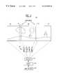
- FIG. 1shows a diagram of a typical large multichannel display system 100 .
- System 100includes three smaller screens (e.g., 20 feet by 30 feet), screen 101 , screen 102 , and screen 103 , that are combined to form a single very large display (e.g., 20 feet by 90 feet). Areas 110 and 110 show the junctions between the screens. Screens 101 - 103 function coherently in order to create the large display (e.g., 20 feet by 90 feet) seen by a group of users 105 .
- screens 101 - 103are projection type screens, with the images projected from an image projector 130 .
- Image projector 130receives video information from an image generator 132 via a blender 131 .
- edges between the channels of screens 101 - 103 , “blend regions” 110 and 111need to blend seamlessly in order to create the large image. This has proven problematic. As with most arrayed multichannel displays, the edges of the combined channels must be blended such that the “seams” are as unnoticeable as possible.
- projection type multichannel displayse.g., system 100
- one typical prior art approachis to overlap the edges of the image from each video feed in order to create a smooth transition from the image of one channel to the next, in order to smooth the seams of areas 110 and 111 . This requires some overlap of the video from each image and requires that the brightness of one image reduces as the other increases in the overlap region, areas 110 and 111 .
- the brightness levels of the channelsneed to be precisely controlled. However, achieving this level of control often requires the incorporation of expensive, dedicated hardware within image generator unit 130 .
- FIG. 2shows system 100 in greater detail.
- the image generator 132includes graphics computers 241 - 243 for generating the video information for each video channel.
- Computers 241 - 243are respectively coupled to image blenders 251 - 253 , which are in turn coupled to projectors 201 - 203 .
- Projectors 201 - 203function by projecting the video information received from computers 241 - 243 and image blenders 251 - 253 onto their respective one of screens 101 - 103 .
- System 100includes dedicated image blenders 251 - 253 for performing the precise brightness control required to implement the seamless overlap of screens 101 - 103 .
- Computers 241 - 243include graphics processing hardware and software and function by generating the video information for each respective channel for screens 101 - 103 .
- Blenders 251 - 253perform brightness processing on the video information received from computers 241 - 243 .
- Image blenders 251 - 253are dedicated, special purpose hardware components which process the video information emerging from computers 241 - 243 .
- the image blenders 251 - 253are format/hardware implementation specific, in that they are not readily interchangeable among display systems from different manufacturers. Because of the required level of fidelity, image blenders 251 - 253 are relatively complex and expensive, adding significantly to the overall complexity and cost of system 100 .
- the present inventionis a method and system for implementing high fidelity blending for multichannel displays without requiring the use of a dedicated blending hardware for processing video information after it emerges from an image generator.
- the present inventionprovides a system which can be efficiently implemented on multiple computer system platforms.
- the system of the present inventionis inexpensive, and does not require additional, dedicated hardware for its implementation.
- the present inventionis implemented as an edge blending process executed on a graphics computer system included within the image generator.
- the computer system included within the image generatorperforms the edge blending processing on the gamma-corrected image before it is taken from the frame buffer or sent to video. This eliminates the need for a separate dedicated blending hardware unit, as required with prior art multichannel display systems.
- the computer systems included within the image generatorperform the edge blending processing on each of the video frames of the channels such that as the video information emerges from the image generator each of the video frames includes the necessary blending required for creating a seamless multichannel display.
- the blending process of the present inventionoccurs as the information is being rendered by the computer systems. For example, As a left computer generated frame is rendered for display on a first video channel, a calculated blend geometry is rendered onto that frame to modulate the brightness in the blend/overlap region, resulting in a first blended frame. This occurs before the frame is sent to video. As a right frame is rendered for display on a second channel, a second complimentary blend geometry is rendered onto the second frame to modulate the brightness of the second frame in the blend/overlap region, resulting in a second blended frame.
- the overly regions of these blended frameshave their respective brightness levels modulated such that when the first and second blended frames are sent to video and projected onto adjacent first and second screens, the resulting images overlap within the overlap regions and combine such that the first and second overlap regions precisely align. In this manner, the image from the first blended video frame and the image from the second blended video frame form a seamless junction between the two, thereby implementing a high fidelity multichannel display.
- FIG. 1shows a diagram of a prior art multichannel image generator and display system.
- FIG. 2shows a diagram of the multichannel image generator and display system of FIG. 1 in greater detail.
- FIG. 3shows a diagram of a multichannel image generator and display system in accordance with one embodiment of the present invention to.
- FIG. 4shows a diagram of the typical components of a graphics computer included within an image generator used in a multichannel display system in accordance with one embodiment of present invention.
- FIG. 5shows a diagram of the relationship between the respective video channels of a multichannel display system in accordance with one embodiment of present invention.
- FIG. 6shows a diagram of the overly regions of the center channel of the multichannel display system of FIG. 5 .
- FIG. 7shows a pre-blended depiction and a post-blended depiction of the image displayed via channel 2 in accordance with one embodiment of present invention.
- FIG. 8depicts a series of diagrams representative of the brightness level of the image information within the frame buffer of one of the graphics computers in accordance with one embodiment of present invention.
- FIG. 9shows a diagram depicting a multi-polygon rendering method for implementing the overly regions in accordance with one embodiment of present invention.
- FIG. 10shows a diagram depicting the effect on the brightness level of an image as the multiple polygons from FIG. 9 are blended into the image.
- FIG. 11shows a diagram of a one-dimensional texture rendering method for implementing the overly regions in accordance with one embodiment of the present invention.
- FIG. 12shows a diagram depicting one possible brightness profile of an image resulting from the method depicted in FIG. 11 .
- FIG. 13shows a diagram depicting an alpha mask rendering method for implementing the overlap regions in accordance with one embodiment of present invention.
- FIG. 14shows a diagram depicting an image read back from texture memory method for implementing the overlap regions in accordance with one embodiment of present invention.
- FIG. 15shows a flow chart of the steps of a blending process in accordance with one embodiment of present invention.
- FIG. 16shows a flow chart of the steps of an alternative blending process in accordance with one embodiment of present invention.
- graphics subsystemscan apply not only to graphics computers, but to any computer based image generator, such as, for example, a simple computer image generator having simple controlling hardware and which connects directly to data base memory or a mass storage device.
- the present inventionis a method and system for implementing high fidelity blending for multichannel displays without requiring the use of a dedicated blending hardware for processing video information after it emerges from image generation.
- the present inventionprovides a system which can be efficiently implemented on multiple computer system platforms.
- the system of the present inventionis inexpensive, and does not require additional, dedicated hardware for its implementation. The present invention and its benefits are further described below.
- system 300includes three large projection-type screens 301 - 303 (e.g., 20 feet by 30 feet) which combine to form a single very large, high fidelity display (e.g., 20 feet by 90 feet).
- the large displayis capable of presenting, seamless, high fidelity graphics which span the entire area of screens 301 - 303 .
- Fidelityis implemented by achieving a seamless overlap of the images of each of the screens 301 - 303 .
- the overlapoccurs in a first and second overlap region, region 310 and region 311 .
- the image from the each of the channelsoverlaps the image each adjacent channel by a predetermined amount.
- the images of channel 1overlaps the images of channel 2 in overlap region 310 , and likewise for channel 2 and channel 3 in overlap region 311 .
- the brightness levels of the images of the respective channelsis precisely determined and controlled such that a seamless junction is created between the images.
- the process of determining an controlling the brightness levelsis implemented within an image generator unit 330 , as opposed to using a separate blending unit.
- Image generator 330includes three graphics computer systems (e.g., high performance graphics workstations) which generate the computer graphics information for each respective channel.
- the blending process of the present inventionis implemented within the graphics subsystems of the graphics computers.
- the image information emerging from the graphics computersincludes all the necessary blending required for overlap regions 310 and 311 . Hence, no additional processing need be performed on the information emerging from the graphics computers 320 - 322 .
- the video informationis coupled directly to image projectors 301 - 303 , for projection onto screens 301 - 303 . Since each video frame has been previously blended within the graphics pipelines of computer systems 320 322 , the images of screens 301 - 303 will blend seamlessly within overlap regions 310 and 311 .
- the system of the present inventionis much more efficient than comparable prior art multichannel display systems.
- the present inventioneliminates the requirement for an external, dedicated blending unit as required in typical prior art systems. This makes system 300 less expensive less expensive than comparable prior art systems.
- System 300implements high fidelity blending for multichannel displays without requiring the use of a dedicated blending hardware for processing video information after it emerges from image generation (e.g., emerges from graphics computers 320 - 322 ). Consequently, system 300 can be more easily and efficiently implemented on different types of computer system platforms.
- System 321includes any computer graphics systems for generating complex or 3 dimensional images.
- Computer system 321includes a bus 401 for transmitting digital information between the various parts of the computer system.
- One or more microprocessors 402are coupled to bus 401 for processing information.
- the information along with the instructions of how the information is to be processedare stored in a hierarchical memory system comprised of mass storage device 407 , read only memory 406 , and main memory 404 .
- Mass storage device 407is used to store large amounts of digital data.
- the mass storage device 407can consist one or more hard disk drives, floppy disk drives, optical disk drives, tape drives, CD ROM drives, or any number of other types of storage devices having media for storing data digitally.
- a read only memory (ROM) 406is used to store digital data of a permanent basis, such as instructions for the microprocessors.
- Main memory 404is used for storing digital data on an intermediate basis.
- Main memory 404can be dynamic random access memory (DRAM).
- a 3D graphics rendering system 411is an option which can be included in system 321 .
- Processor 402provides the graphics system 411 with graphics data, such as drawing Commands, coordinate vertex data, and other data related to an object's geometric position, color, texture, shading, and other surface parameters.
- the object datais processed by graphics system 411 in the following four pipelined stages: geometry subsystem 431 , scan conversion subsystem 432 , raster subsystem 433 , and a video subsystem 434 .
- the geometry subsystem 431converts the graphical data from processor 402 into a screen coordinate system. It is the function of the geometry subsystem 431 to perform the projection and transformation process to give depth to a displayed object.
- the resulting primitives (points, lines, polygons, polyhedra, and the like) supplied by the geometry subsystem 431are then supplied to the scan conversion subsystem 432 . It is the function of the scan conversion subsystem 432 to then generate pixel data (e.g., fragments, fragment parameters, color information, and the like) based on these primitives.
- the scan conversion subsystem 432performs the interpolation functions to interpolate straight lines so that each intermediate value need not be individually and separately calculated by the geometry subsystem.
- the pixel datais sent to the raster subsystem 433 , whereupon Z-buffering, blending, texturing (using texture data stored in texture memory 436 ), and antialiasing functions are performed.
- the resulting pixel valuesare subsequently stored in frame buffer 435 , and the Z values are stored in the Z buffer 410 .
- the video subsystem 434reads the frame buffer 435 , gamma corrects the image information stored therein, and sends the image (in the correct format) to the monitor 421 .
- the video informationis also output from frame buffer 435 to projector 331 for projection onto screen 302 .
- an alphanumeric keyboard 422is used for inputting commands and other information to processor 402 .
- cursor control device 423a mouse, trackball, joystick, and the like
- cursor control device 423a mouse, trackball, joystick, and the like
- a hard copy device 424e.g., a laser printer
- a sound recording or video option 425can be coupled to the system 321 to provide multimedia capabilities.
- Graphics computers 320 and 322are each substantially similar to graphics computer 321 . As with graphics computer 321 , workstations 320 and 322 function by generating the image information required for projection onto their respective screens 301 and 303 .
- FIG. 5shows the location of channel 2 with respect to channels 1 and 3 .
- FIG. 6shows the image of channel 2 without any overlap from channels 1 and 3 .
- each of the channelse.g., channels 1 - 3
- the brightness of the image displayeddecreases in the regions 310 and 311 . This is so that when channel 2 's image is overlapped on the images of channels 1 and 3 , the seam between channels 1 , 2 , and 3 will not be noticeable.
- this blendingwas performed using a separate, discreet, blending processor or device. In accordance with the present invention, this blending is performed within the graphics subsystem as the image is being generated.
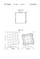
- FIG. 7shows a pre-blended depiction and a post-blended depiction of the image displayed via channel 2 .
- the pre-blended depictionis on the left side of FIG. 7 and the post-blended depiction is on the right side of FIG. 7 .
- Beneath each depictionis a corresponding diagram of the brightness level of the pre-blended and post-blended images, where brightness level is shown in the vertical direction and the horizontal dimension of the respective image is shown in the horizontal direction.
- the brightness level of the pre-blended imageis uniform across the horizontal dimensions of the image.
- the brightness levelis decreased at the far left and far right edges of the image, the overlap regions 310 and 311 .
- the far right brightness level of the image from channel 1decreases so that when the two channels are overlapped, the brightness level is uniform across both channels.
- the far left brightness level of the image from channel 3decreases so that when channels 2 and 3 are overlapped, the brightness level is uniform across them.
- channels 1 , 2 , and 3are blended to create the single large display, as the decreased brightness levels of the overlap regions 310 and 311 combine to obtain a nominal brightness level.
- the blendingis determined by and derived from the geometry of the display system.
- the present inventionis not limited to the simple geometry, but can support arbitrary blend shapes as determined by the particular requirements of the display design.
- FIG. 8depicts a series of diagrams representative of the brightness level of the image information within the frame buffer of one of the graphics computers 320 - 322 (e.g., workstation 321 ).
- the left column of FIG. 8shows two diagrams (diagram 801 and diagram 804 ) representing the brightness level of the contents of the frame buffer.
- the center column of FIG. 8shows two diagrams (diagrams 802 and 805 ) of the gamma level of the screen (e.g., screen 302 ), and the right column shows two diagrams (diagrams 803 and 806 ) of the brightness level of the screen (e.g., display screen 302 ) as actually seen by a user.
- FIG. 8depicts a case where blending is improperly implemented.
- the three diagrams on the bottom row FIG. 8depict a case where, in accordance with present invention, blending is properly implemented.
- the blendingis performed as the image information is being rendered into the frame buffer of the workstation (e.g., workstation 321 ).
- Diagram 801 and diagram 804represent the brightness level of the post blended image stored within the frame buffer (e.g., frame buffer 435 ). To achieve uniform nominal brightness on display screen 302 , it is important that the post blended image is processed to take into account the gamma level of the screen 302 .
- the top row of FIG. 8depicts a case where this is improperly implemented.
- a nonuniform brightness resultse.g., diagram 803
- the blending performed on the image rendered into the frame buffer 435did not properly take into account the gamma level of the screen 302 . This is for a situation where gamma correction is not supported in the video system 434 of the graphics subsystem 411 .
- the bottom row of FIG. 8depicts a case where the blending is properly implemented.
- the imageis rendered into frame buffer 435 in such a manner as to account for the gamma level of the screen 302 .
- the present inventionis able to take into account the gamma characteristics of each of the projectors 330 - 332 .
- the imagesare rendered into the frame buffer with their respective overlap regions blended in consideration of the gamma characteristics of the respective screens. Since the blending process of the present invention occurs as the images are being rendered, the present invention can be easily adjusted in light of the gamma characteristics of any particular screen.
- FIG. 9shows one method in accordance with present invention for generating the blended overlap regions.
- the brightness controlis achieved by using the graphics processing capabilities of the graphics subsystem (e.g., graphics subsystem 411 ) of the graphics computer (e.g., graphics computer 321 ).
- a set of polygonsare drawn across the overlap regions of a rendered image (e.g., the image rendered into the frame buffer 435 that is to be processed and subsequently displayed on one of screens 301 - 302 ).
- Each of the polygonshas a respective transparency value (e.g., alpha) and a color value.
- the process of the present inventionblends the image 900 by multiplying the image intensity by the intensity described by the color and/or transparency values of the polygons 901 - 905 and 906 - 910 .
- Thishas the effect of decreasing the brightness level of the image 900 in the manner required to accomplish the seamless blend (e.g., the post blend brightness level shown in FIG. 7 ).
- the blend intensity of each of the polygons 901 - 910can be described in the form of a texture applied to the polygons 901 - 910 or per vertex intensity values.
- FIG. 10shows a diagram depicting the effect on the brightness level of the image 900 as a color of the polygons 906 - 910 are blended in.
- controlling brightness level by blending multiple polygons into the imageresults in a “piecewise linear” approximation of the desired smooth profile from the normal brightness level of the image 900 to the fully dark brightness level of the image, on the far right side of the overlap region, shown by polygon 910 .
- the desired “brightness profile” of the overlap regionsis controlled by adjusting the color/transparency of the multiple polygons, and by increasing or decreasing the number of polygons used to create the brightness profile.
- FIG. 11shows a second method in accordance with the present invention for generating the blended overlap regions using polygons.
- This methodis different from the method shown in FIG. 9 in that instead of using many different polygons (e.g., polygons 901 - 905 and polygons 906 - 910 ) to create the overlap regions, a single polygon is used for each overlap region, polygon 1101 and polygon 1102 .
- Polygons 1101 and 1102both have a respective one-dimensional texture that is used to control their respective brightness.
- the one-dimensional textureincludes a number of samples that describe the color/transparency of the texture.
- the brightness of the underlying image 1100decreases in accordance with the brightness profile described by the one-dimensional texture. This is depicted in FIG. 12 below.
- FIG. 12shows the brightness profile of the polygon 1102 as described by the samples, n, of the one-dimensional texture that is mapped onto polygon 1102 .
- This brightness profilewould be substantially similar to the brightness profile shown in FIG. 10, however, the brightness profile of FIG. 12 is more “continuous” since a larger number of samples are used to describe the profile and more complex shapes could be efficiently represented.
- This methodtends to emphasize the use of the texture hardware of graphics subsystem 411 while the method of FIG. 9 tends to emphasize the use of the geometry and shading hardware of graphics subsystem 411 .
- FIG. 13shows a third method in accordance with present invention for generating the blended overlap regions by using an alpha mask.
- FIG. 13depicts an alpha mask 1301 which is stored into the frame buffer 435 prior to the rendering of an image.
- Alpha mask 1301includes a unique blend modulation value for each pixel in the frame buffer 435 . These values are used to create the desired brightness profile for the image when the image is later rendered into the frame buffer 435 .
- each pixel written to the frame bufferis multiplied by the alpha brightness already stored within the frame buffer 435 . This results in an image with a correctly modulated brightness intensity, ready to be sent to projector 331 .
- alpha masksto implement the overlap regions.
- the alpha maskreadily allow control of the contour or outline of the boundaries of the overlap regions.
- the alpha maskscan be configured to implement irregularly shaped overlap regions having irregularly shaped boundaries. This helps to obscure the junction between the channels of the display system, reducing the degree to which the seam is noticeable.
- FIGS. 3 through 13show the invention functioning with 3 screens horizontally aligned, it should be appreciated that the blending process of the present invention can be applied to multichannel displays having any number of screens arrayed in any number of configuration (e.g., tiled, stacked, etc.).
- FIG. 14shows a fourth method for generating the blended overlap regions in accordance with one embodiment of the present invention.
- this methodall or parts of the image in the frame buffer 435 are copied back to texture memory 436 within graphics subsystem 411 .
- This image informationconstitutes data which can be applied as a texture on to one or more polygons rendered into the frame buffer 435 , where the underlying color of the polygon or polygons is used to modulated the color of the “texture” from texture memory 436 (where this texture comprises the image that was read from frame buffer 435 to texture memory 436 ).
- the left side of FIG. 14shows an image mapped onto a polygon mesh prior to subdivision and its corresponding pre-blend brightness profile.
- the image 14shows the image mapped onto the polygon mesh after the mesh has been subdivided in the overlap regions and its corresponding post-blend brightness profile.
- the overlap regionsare on each edge of the image (e.g., top, bottom, left, and right).
- values of the n samplesmay be specified at a per vertex level, resulting in the texture intensity being modulated on application to the frame buffer.
- this methodis similar to distortion correction solutions and other solutions where an image in texture memory is applied to an image stored within the frame buffer using a texturing operation, such as in, for example, video playback or texture read back, antialiasing, and the like.
- Process 1500depicts the steps of a blending process used by system in accordance with present invention (e.g., system 300 ), where polygons are used to implement overlap regions, as the image information is being generated within an image generator (e.g., image generator 330 ).
- system in accordance with present inventione.g., system 300
- polygonsare used to implement overlap regions, as the image information is being generated within an image generator (e.g., image generator 330 ).
- Process 1500begins in step 1501 , where the graphics computers (e.g., graphics computers 320 - 322 ) within the image generator 330 execute graphics applications which generate the images for display.
- the graphics applicationexecuting on the processors of the workstations (e.g., graphics computer 321 ) renders an image into the frame buffer (e.g., frame buffer 435 ) of the graphics subsystem (e.g., graphics subsystem 411 ).
- the image stored in the frame buffer 435is processed to create the necessary overlap regions (e.g., overlap regions 310 - 311 ). As described above in the discussion of FIGS.
- polygonsare rendered into the frame buffer “over” the image stored into frame buffer in order to create the desired brightness profile.
- a series of polygonscan be rendered over the image stored in the frame buffer, where each polygon has a different color/transparency value, in order to implement the desired brightness profile.
- a one-dimensional texture having a plurality of color/transparency samplescan be mapped onto a single polygon, and that single polygon be used to implement and overlap region on top of the image stored within the frame buffer.
- step 1504the blended image in the frame buffer 435 is converted into video format and sent to a video projector (e.g., image projector 331 ).
- a video projectore.g., image projector 331
- the blended imageis then projected by image projector 321 onto the respective screen (e.g., screen 302 ).
- Process 1500is performed by each of the graphics computers within image generator 330 , resulting in a seamless blended multichannel display for viewing by the user. As shown by step 1506 , this process continues as the graphics application continues to function.
- Process 1600is substantially similar to process 1500 of FIG. 15 . However, and process 1600 , as opposed to using polygons to implement the overlap regions 310 - 311 , an alpha mask (e.g., alpha mask 1301 from FIG. 13) is used.
- an alpha maske.g., alpha mask 1301 from FIG. 13
- Process 1600begins in step 1601 , where a graphics application is executed.
- the graphics applicationsends image information to the graphics subsystem 411 .
- an alpha maskis rendered into the frame buffer 435 of the graphics subsystem 411 .
- image from the graphics applicationis then rendered into the frame buffer of the graphics subsystem, “on top of” the alpha mask.
- this processresults in the image being blended within the overlap regions 310 as required.
- the resulting blended imageis then converted to video format and sent to the image projector 331 .
- the blended imageis projected onto screen 302 by the image projector 331 .
- process 1600continues as the graphics application continues to run, thereby implementing the seamless multichannel image for viewing by the user.
- the present inventionprovides method for implementing edge blending between a multiple video channels to create a seamless multichannel display system.
- the present inventionprovides a method and system for implementing high fidelity blending for multichannel displays without requiring the use of a dedicated blending hardware for processing video information after it emerges from image generation.
- the present inventionprovides a system which can be efficiently implemented on multiple computer system platforms. Additionally, the system of the present invention is inexpensive, and does not require additional, dedicated hardware for its implementation.
Landscapes
- Engineering & Computer Science (AREA)
- Theoretical Computer Science (AREA)
- Multimedia (AREA)
- Human Computer Interaction (AREA)
- Physics & Mathematics (AREA)
- General Engineering & Computer Science (AREA)
- General Physics & Mathematics (AREA)
- Signal Processing (AREA)
- Computer Graphics (AREA)
- Controls And Circuits For Display Device (AREA)
- Image Generation (AREA)
Abstract
Description
Claims (32)
Priority Applications (1)
| Application Number | Priority Date | Filing Date | Title |
|---|---|---|---|
| US09/231,405US6545685B1 (en) | 1999-01-14 | 1999-01-14 | Method and system for efficient edge blending in high fidelity multichannel computer graphics displays |
Applications Claiming Priority (1)
| Application Number | Priority Date | Filing Date | Title |
|---|---|---|---|
| US09/231,405US6545685B1 (en) | 1999-01-14 | 1999-01-14 | Method and system for efficient edge blending in high fidelity multichannel computer graphics displays |
Publications (1)
| Publication Number | Publication Date |
|---|---|
| US6545685B1true US6545685B1 (en) | 2003-04-08 |
Family
ID=22869112
Family Applications (1)
| Application Number | Title | Priority Date | Filing Date |
|---|---|---|---|
| US09/231,405Expired - LifetimeUS6545685B1 (en) | 1999-01-14 | 1999-01-14 | Method and system for efficient edge blending in high fidelity multichannel computer graphics displays |
Country Status (1)
| Country | Link |
|---|---|
| US (1) | US6545685B1 (en) |
Cited By (101)
| Publication number | Priority date | Publication date | Assignee | Title |
|---|---|---|---|---|
| US20020024612A1 (en)* | 2000-08-30 | 2002-02-28 | Takaaki Gyoten | Video projecting system |
| US20020067864A1 (en)* | 2000-11-15 | 2002-06-06 | Masatoshi Matsuhira | Image processing device and image processing method |
| US20020158877A1 (en)* | 2000-11-22 | 2002-10-31 | Guckenberger Ronald James | Shadow buffer control module method and software construct for adjusting per pixel raster images attributes to screen space and projector features for digital wrap, intensity transforms, color matching, soft-edge blending and filtering for multiple projectors and laser projectors |
| US20020180727A1 (en)* | 2000-11-22 | 2002-12-05 | Guckenberger Ronald James | Shadow buffer control module method and software construct for adjusting per pixel raster images attributes to screen space and projector features for digital warp, intensity transforms, color matching, soft-edge blending, and filtering for multiple projectors and laser projectors |
| US20020196369A1 (en)* | 2001-06-01 | 2002-12-26 | Peter Rieder | Method and device for displaying at least two images within one combined picture |
| US20040169724A1 (en)* | 2002-12-09 | 2004-09-02 | Ekpar Frank Edughom | Method and apparatus for creating interactive virtual tours |
| US20050078118A1 (en)* | 2000-05-12 | 2005-04-14 | Microsoft Corporation | Table indexing system and method |
| US6940504B1 (en)* | 2000-11-21 | 2005-09-06 | Microsoft Corporation | Rendering volumetric fog and other gaseous phenomena using an alpha channel |
| US20050287449A1 (en)* | 2004-06-28 | 2005-12-29 | Geert Matthys | Optical and electrical blending of display images |
| US20060007406A1 (en)* | 2002-10-21 | 2006-01-12 | Sean Adkins | Equipment, systems and methods for control of color in projection displays |
| US20060092175A1 (en)* | 2000-11-21 | 2006-05-04 | Microsoft Corporation | Rendering Volumetric Fog and Other Gaseous Phenomena |
| US20060104541A1 (en)* | 2004-11-15 | 2006-05-18 | Baker Henry H | Methods and systems for producing seamless composite images without requiring overlap of source images |
| US20060209057A1 (en)* | 2005-03-15 | 2006-09-21 | Niranjan Damera-Venkata | Projection of overlapping sub-frames onto a surface |
| US7193654B2 (en)* | 2000-07-03 | 2007-03-20 | Imax Corporation | Equipment and techniques for invisible seaming of multiple projection displays |
| US20070103652A1 (en)* | 2003-12-30 | 2007-05-10 | Nijim Yousef W | System and method for smoothing seams in tiled displays |
| US7224411B2 (en) | 2000-03-31 | 2007-05-29 | Imax Corporation | Digital projection equipment and techniques |
| US20070188719A1 (en)* | 2006-02-15 | 2007-08-16 | Mersive Technologies, Llc | Multi-projector intensity blending system |
| US20070195285A1 (en)* | 2006-02-15 | 2007-08-23 | Mersive Technologies, Llc | Hybrid system for multi-projector geometry calibration |
| US20070242240A1 (en)* | 2006-04-13 | 2007-10-18 | Mersive Technologies, Inc. | System and method for multi-projector rendering of decoded video data |
| US20070268306A1 (en)* | 2006-04-21 | 2007-11-22 | Mersive Technologies, Inc. | Image-based parametric projector calibration |
| US20070273795A1 (en)* | 2006-04-21 | 2007-11-29 | Mersive Technologies, Inc. | Alignment optimization in image display systems employing multi-camera image acquisition |
| US7336277B1 (en)* | 2003-04-17 | 2008-02-26 | Nvidia Corporation | Per-pixel output luminosity compensation |
| US20080106653A1 (en)* | 2006-11-06 | 2008-05-08 | Harris Scott C | Spatial Light Modulator Techniques for Stage Lighting |
| US20080129967A1 (en)* | 2006-04-21 | 2008-06-05 | Mersive Technologies, Inc. | Projector operation through surface fitting of 3d measurements |
| US20080180467A1 (en)* | 2006-04-13 | 2008-07-31 | Mersive Technologies, Inc. | Ultra-resolution display technology |
| US20080266321A1 (en)* | 2007-04-30 | 2008-10-30 | Richard Aufranc | System and method for masking and overlaying images in multiple projector system |
| US20090024448A1 (en)* | 2007-03-29 | 2009-01-22 | Neurofocus, Inc. | Protocol generator and presenter device for analysis of marketing and entertainment effectiveness |
| US20090024449A1 (en)* | 2007-05-16 | 2009-01-22 | Neurofocus Inc. | Habituation analyzer device utilizing central nervous system, autonomic nervous system and effector system measurements |
| US20090036756A1 (en)* | 2007-07-30 | 2009-02-05 | Neurofocus, Inc. | Neuro-response stimulus and stimulus attribute resonance estimator |
| US20090036755A1 (en)* | 2007-07-30 | 2009-02-05 | Neurofocus, Inc. | Entity and relationship assessment and extraction using neuro-response measurements |
| US20090083129A1 (en)* | 2007-09-20 | 2009-03-26 | Neurofocus, Inc. | Personalized content delivery using neuro-response priming data |
| US20090135200A1 (en)* | 2005-06-28 | 2009-05-28 | Mark Alan Schultz | Selective Edge Blending Based on Displayed Content |
| US20090167949A1 (en)* | 2006-03-28 | 2009-07-02 | David Alan Casper | Method And Apparatus For Performing Edge Blending Using Production Switchers |
| US20090262260A1 (en)* | 2008-04-17 | 2009-10-22 | Mersive Technologies, Inc. | Multiple-display systems and methods of generating multiple-display images |
| US20100079489A1 (en)* | 2008-10-01 | 2010-04-01 | Ati Technologies Ulc | System and method for efficient digital video composition |
| CN101727878A (en)* | 2009-12-15 | 2010-06-09 | 王晓年 | Single host projection integration system and realizing method thereof |
| US20100183279A1 (en)* | 2009-01-21 | 2010-07-22 | Neurofocus, Inc. | Methods and apparatus for providing video with embedded media |
| US20100186031A1 (en)* | 2009-01-21 | 2010-07-22 | Neurofocus, Inc. | Methods and apparatus for providing personalized media in video |
| US20100195003A1 (en)* | 2009-02-04 | 2010-08-05 | Seiko Epson Corporation | Projector, projection system, image display method, and image display program |
| US20100249636A1 (en)* | 2009-03-27 | 2010-09-30 | Neurofocus, Inc. | Personalized stimulus placement in video games |
| US20100249538A1 (en)* | 2009-03-24 | 2010-09-30 | Neurofocus, Inc. | Presentation measure using neurographics |
| US20100309336A1 (en)* | 2009-06-05 | 2010-12-09 | Apple Inc. | Skin tone aware color boost for cameras |
| US7859542B1 (en) | 2003-04-17 | 2010-12-28 | Nvidia Corporation | Method for synchronizing graphics processing units |
| US20110046504A1 (en)* | 2009-08-20 | 2011-02-24 | Neurofocus, Inc. | Distributed neuro-response data collection and analysis |
| US20110078762A1 (en)* | 2009-09-29 | 2011-03-31 | Ebay, Inc. | Mobile or user device authentication and tracking |
| US20110106621A1 (en)* | 2009-10-29 | 2011-05-05 | Neurofocus, Inc. | Intracluster content management using neuro-response priming data |
| US20110119124A1 (en)* | 2009-11-19 | 2011-05-19 | Neurofocus, Inc. | Multimedia advertisement exchange |
| US20110119129A1 (en)* | 2009-11-19 | 2011-05-19 | Neurofocus, Inc. | Advertisement exchange using neuro-response data |
| US20110128294A1 (en)* | 2009-11-27 | 2011-06-02 | Canon Kabushiki Kaisha | Image processing apparatus and image processing method |
| US20110237971A1 (en)* | 2010-03-25 | 2011-09-29 | Neurofocus, Inc. | Discrete choice modeling using neuro-response data |
| US8251512B2 (en) | 2004-07-08 | 2012-08-28 | Imax Corporation | Equipment and methods for the display of high resolution images using multiple projection displays |
| US8386313B2 (en) | 2007-08-28 | 2013-02-26 | The Nielsen Company (Us), Llc | Stimulus placement system using subject neuro-response measurements |
| US8386312B2 (en) | 2007-05-01 | 2013-02-26 | The Nielsen Company (Us), Llc | Neuro-informatics repository system |
| US8392255B2 (en) | 2007-08-29 | 2013-03-05 | The Nielsen Company (Us), Llc | Content based selection and meta tagging of advertisement breaks |
| US8392253B2 (en) | 2007-05-16 | 2013-03-05 | The Nielsen Company (Us), Llc | Neuro-physiology and neuro-behavioral based stimulus targeting system |
| US8392250B2 (en) | 2010-08-09 | 2013-03-05 | The Nielsen Company (Us), Llc | Neuro-response evaluated stimulus in virtual reality environments |
| US8392251B2 (en) | 2010-08-09 | 2013-03-05 | The Nielsen Company (Us), Llc | Location aware presentation of stimulus material |
| US8392254B2 (en) | 2007-08-28 | 2013-03-05 | The Nielsen Company (Us), Llc | Consumer experience assessment system |
| US8396744B2 (en) | 2010-08-25 | 2013-03-12 | The Nielsen Company (Us), Llc | Effective virtual reality environments for presentation of marketing materials |
| US20130120812A1 (en)* | 2008-12-24 | 2013-05-16 | Samsung Electronics Co., Ltd. | Image processing apparatus and method of controlling the same |
| US8494905B2 (en) | 2007-06-06 | 2013-07-23 | The Nielsen Company (Us), Llc | Audience response analysis using simultaneous electroencephalography (EEG) and functional magnetic resonance imaging (fMRI) |
| US8494610B2 (en) | 2007-09-20 | 2013-07-23 | The Nielsen Company (Us), Llc | Analysis of marketing and entertainment effectiveness using magnetoencephalography |
| US20130258289A1 (en)* | 2012-03-29 | 2013-10-03 | Seiko Epson Corporation | Projection type display device, display system, and display method |
| US8635105B2 (en) | 2007-08-28 | 2014-01-21 | The Nielsen Company (Us), Llc | Consumer experience portrayal effectiveness assessment system |
| US8655437B2 (en) | 2009-08-21 | 2014-02-18 | The Nielsen Company (Us), Llc | Analysis of the mirror neuron system for evaluation of stimulus |
| US8655428B2 (en) | 2010-05-12 | 2014-02-18 | The Nielsen Company (Us), Llc | Neuro-response data synchronization |
| US8989835B2 (en) | 2012-08-17 | 2015-03-24 | The Nielsen Company (Us), Llc | Systems and methods to gather and analyze electroencephalographic data |
| KR20150066936A (en)* | 2013-12-09 | 2015-06-17 | 씨제이씨지브이 주식회사 | Method for image correction at ovelapped region of image, computer readable medium and executing device thereof |
| US20150276142A1 (en)* | 2014-03-25 | 2015-10-01 | Nichia Corporation | Display system |
| US20150288921A1 (en)* | 2012-04-30 | 2015-10-08 | Hewlett-Packard Development Company, L.P. | System and method for providing a two-way interactive 3d experience |
| US9282335B2 (en) | 2005-03-15 | 2016-03-08 | Hewlett-Packard Development Company, L.P. | System and method for coding image frames |
| US20160094821A1 (en)* | 2014-09-25 | 2016-03-31 | Canon Kabushiki Kaisha | Projection type image display apparatus and control method therefor |
| US9320450B2 (en) | 2013-03-14 | 2016-04-26 | The Nielsen Company (Us), Llc | Methods and apparatus to gather and analyze electroencephalographic data |
| US9357240B2 (en) | 2009-01-21 | 2016-05-31 | The Nielsen Company (Us), Llc | Methods and apparatus for providing alternate media for video decoders |
| US9424809B1 (en) | 2013-07-15 | 2016-08-23 | Google Inc. | Patterned projection with multi-panel display |
| CN105940443A (en)* | 2013-07-25 | 2016-09-14 | 英派尔科技开发有限公司 | Composite display with multiple imaging attributes |
| US9454646B2 (en) | 2010-04-19 | 2016-09-27 | The Nielsen Company (Us), Llc | Short imagery task (SIT) research method |
| US9560984B2 (en) | 2009-10-29 | 2017-02-07 | The Nielsen Company (Us), Llc | Analysis of controlled and automatic attention for introduction of stimulus material |
| US9569986B2 (en) | 2012-02-27 | 2017-02-14 | The Nielsen Company (Us), Llc | System and method for gathering and analyzing biometric user feedback for use in social media and advertising applications |
| US9622702B2 (en) | 2014-04-03 | 2017-04-18 | The Nielsen Company (Us), Llc | Methods and apparatus to gather and analyze electroencephalographic data |
| US9886981B2 (en) | 2007-05-01 | 2018-02-06 | The Nielsen Company (Us), Llc | Neuro-feedback based stimulus compression device |
| US9910275B2 (en)* | 2015-05-18 | 2018-03-06 | Samsung Electronics Co., Ltd. | Image processing for head mounted display devices |
| US9936250B2 (en) | 2015-05-19 | 2018-04-03 | The Nielsen Company (Us), Llc | Methods and apparatus to adjust content presented to an individual |
| US10146304B2 (en) | 2014-11-10 | 2018-12-04 | Irisvision, Inc. | Methods and apparatus for vision enhancement |
| CN110225323A (en)* | 2019-06-04 | 2019-09-10 | 成都信息工程大学 | High-precision multi-projector image entirety and edge brightness fusing device |
| US10496352B2 (en) | 2015-03-03 | 2019-12-03 | Aten International Co., Ltd. | Calibration system and method for multi-image output system |
| US10963999B2 (en) | 2018-02-13 | 2021-03-30 | Irisvision, Inc. | Methods and apparatus for contrast sensitivity compensation |
| US10987015B2 (en) | 2009-08-24 | 2021-04-27 | Nielsen Consumer Llc | Dry electrodes for electroencephalography |
| US11094139B2 (en)* | 2018-06-26 | 2021-08-17 | Quantificare S.A. | Method and device to simulate, visualize and compare surface models |
| US11144119B2 (en) | 2015-05-01 | 2021-10-12 | Irisvision, Inc. | Methods and systems for generating a magnification region in output video images |
| US11284054B1 (en) | 2018-08-30 | 2022-03-22 | Largo Technology Group, Llc | Systems and method for capturing, processing and displaying a 360° video |
| US11372479B2 (en) | 2014-11-10 | 2022-06-28 | Irisvision, Inc. | Multi-modal vision enhancement system |
| US11481788B2 (en) | 2009-10-29 | 2022-10-25 | Nielsen Consumer Llc | Generating ratings predictions using neuro-response data |
| US20220360839A1 (en)* | 2021-05-05 | 2022-11-10 | Disney Enterprises, Inc. | Accessibility Enhanced Content Delivery |
| US11546527B2 (en) | 2018-07-05 | 2023-01-03 | Irisvision, Inc. | Methods and apparatuses for compensating for retinitis pigmentosa |
| US11704681B2 (en) | 2009-03-24 | 2023-07-18 | Nielsen Consumer Llc | Neurological profiles for market matching and stimulus presentation |
| US20230331162A1 (en)* | 2022-04-13 | 2023-10-19 | Panasonic Intellectual Property Management Co., Ltd. | Display controller |
| US20230419437A1 (en)* | 2016-09-30 | 2023-12-28 | Qualcomm Incorporated | Systems and methods for fusing images |
| US12205211B2 (en) | 2021-05-05 | 2025-01-21 | Disney Enterprises, Inc. | Emotion-based sign language enhancement of content |
| US12388973B2 (en) | 2018-08-30 | 2025-08-12 | Hermelo Miranda | Systems and method for capturing, processing, and displaying a 360° video |
| WO2025189366A1 (en)* | 2024-03-13 | 2025-09-18 | Qualcomm Incorporated | Display processing unit extension for very large aspect ratio automotive display screen |
Citations (5)
| Publication number | Priority date | Publication date | Assignee | Title |
|---|---|---|---|---|
| US4974073A (en)* | 1988-01-14 | 1990-11-27 | Metavision Inc. | Seamless video display |
| US5136390A (en)* | 1990-11-05 | 1992-08-04 | Metavision Corporation | Adjustable multiple image display smoothing method and apparatus |
| US5896136A (en)* | 1996-10-30 | 1999-04-20 | Hewlett Packard Company | Computer graphics system with improved blending |
| US6126548A (en)* | 1997-10-08 | 2000-10-03 | Illusion, Inc. | Multi-player entertainment system |
| US6184903B1 (en)* | 1996-12-27 | 2001-02-06 | Sony Corporation | Apparatus and method for parallel rendering of image pixels |
- 1999
- 1999-01-14USUS09/231,405patent/US6545685B1/ennot_activeExpired - Lifetime
Patent Citations (5)
| Publication number | Priority date | Publication date | Assignee | Title |
|---|---|---|---|---|
| US4974073A (en)* | 1988-01-14 | 1990-11-27 | Metavision Inc. | Seamless video display |
| US5136390A (en)* | 1990-11-05 | 1992-08-04 | Metavision Corporation | Adjustable multiple image display smoothing method and apparatus |
| US5896136A (en)* | 1996-10-30 | 1999-04-20 | Hewlett Packard Company | Computer graphics system with improved blending |
| US6184903B1 (en)* | 1996-12-27 | 2001-02-06 | Sony Corporation | Apparatus and method for parallel rendering of image pixels |
| US6126548A (en)* | 1997-10-08 | 2000-10-03 | Illusion, Inc. | Multi-player entertainment system |
Cited By (192)
| Publication number | Priority date | Publication date | Assignee | Title |
|---|---|---|---|---|
| US7224411B2 (en) | 2000-03-31 | 2007-05-29 | Imax Corporation | Digital projection equipment and techniques |
| US20050078118A1 (en)* | 2000-05-12 | 2005-04-14 | Microsoft Corporation | Table indexing system and method |
| US7193654B2 (en)* | 2000-07-03 | 2007-03-20 | Imax Corporation | Equipment and techniques for invisible seaming of multiple projection displays |
| US20020024612A1 (en)* | 2000-08-30 | 2002-02-28 | Takaaki Gyoten | Video projecting system |
| US6753923B2 (en)* | 2000-08-30 | 2004-06-22 | Matsushita Electric Industrial Co., Ltd. | Video projecting system |
| US20020067864A1 (en)* | 2000-11-15 | 2002-06-06 | Masatoshi Matsuhira | Image processing device and image processing method |
| US6898332B2 (en)* | 2000-11-15 | 2005-05-24 | Seiko Epson Corporation | Image processing device and image processing method |
| US20060092175A1 (en)* | 2000-11-21 | 2006-05-04 | Microsoft Corporation | Rendering Volumetric Fog and Other Gaseous Phenomena |
| US6940504B1 (en)* | 2000-11-21 | 2005-09-06 | Microsoft Corporation | Rendering volumetric fog and other gaseous phenomena using an alpha channel |
| US7245301B2 (en) | 2000-11-21 | 2007-07-17 | Microsoft Corporation | Rendering volumetric fog and other gaseous phenomena |
| US7227555B2 (en) | 2000-11-21 | 2007-06-05 | Microsoft Corporation | Rendering volumetric fog and other gaseous phenomena |
| US7046243B1 (en) | 2000-11-21 | 2006-05-16 | Microsoft Corporation | Rendering volumetric fog and other gaseous phenomena |
| US20060103661A1 (en)* | 2000-11-21 | 2006-05-18 | Microsoft Corporation | Rendering Volumetric Fog and Other Gaseous Phenomena |
| US20020180727A1 (en)* | 2000-11-22 | 2002-12-05 | Guckenberger Ronald James | Shadow buffer control module method and software construct for adjusting per pixel raster images attributes to screen space and projector features for digital warp, intensity transforms, color matching, soft-edge blending, and filtering for multiple projectors and laser projectors |
| US20020158877A1 (en)* | 2000-11-22 | 2002-10-31 | Guckenberger Ronald James | Shadow buffer control module method and software construct for adjusting per pixel raster images attributes to screen space and projector features for digital wrap, intensity transforms, color matching, soft-edge blending and filtering for multiple projectors and laser projectors |
| US7050112B2 (en)* | 2001-06-01 | 2006-05-23 | Micronas Gmbh | Method and device for displaying at least two images within one combined picture |
| US20020196369A1 (en)* | 2001-06-01 | 2002-12-26 | Peter Rieder | Method and device for displaying at least two images within one combined picture |
| US20060007406A1 (en)* | 2002-10-21 | 2006-01-12 | Sean Adkins | Equipment, systems and methods for control of color in projection displays |
| US20040169724A1 (en)* | 2002-12-09 | 2004-09-02 | Ekpar Frank Edughom | Method and apparatus for creating interactive virtual tours |
| US7567274B2 (en)* | 2002-12-09 | 2009-07-28 | Frank Edughom Ekpar | Method and apparatus for creating interactive virtual tours |
| US7336277B1 (en)* | 2003-04-17 | 2008-02-26 | Nvidia Corporation | Per-pixel output luminosity compensation |
| US7859542B1 (en) | 2003-04-17 | 2010-12-28 | Nvidia Corporation | Method for synchronizing graphics processing units |
| US7738036B2 (en)* | 2003-12-30 | 2010-06-15 | Thomson Licensing | System and method for smoothing seams in tiled displays |
| US20070103652A1 (en)* | 2003-12-30 | 2007-05-10 | Nijim Yousef W | System and method for smoothing seams in tiled displays |
| US20050287449A1 (en)* | 2004-06-28 | 2005-12-29 | Geert Matthys | Optical and electrical blending of display images |
| US7339625B2 (en)* | 2004-06-28 | 2008-03-04 | Barco N.V. | Optical and electrical blending of display images |
| US8251512B2 (en) | 2004-07-08 | 2012-08-28 | Imax Corporation | Equipment and methods for the display of high resolution images using multiple projection displays |
| US7619658B2 (en)* | 2004-11-15 | 2009-11-17 | Hewlett-Packard Development Company, L.P. | Methods and systems for producing seamless composite images without requiring overlap of source images |
| US20060104541A1 (en)* | 2004-11-15 | 2006-05-18 | Baker Henry H | Methods and systems for producing seamless composite images without requiring overlap of source images |
| US7443364B2 (en)* | 2005-03-15 | 2008-10-28 | Hewlett-Packard Development Company, L.P. | Projection of overlapping sub-frames onto a surface |
| US9282335B2 (en) | 2005-03-15 | 2016-03-08 | Hewlett-Packard Development Company, L.P. | System and method for coding image frames |
| US20060209057A1 (en)* | 2005-03-15 | 2006-09-21 | Niranjan Damera-Venkata | Projection of overlapping sub-frames onto a surface |
| US20090135200A1 (en)* | 2005-06-28 | 2009-05-28 | Mark Alan Schultz | Selective Edge Blending Based on Displayed Content |
| US7866832B2 (en)* | 2006-02-15 | 2011-01-11 | Mersive Technologies, Llc | Multi-projector intensity blending system |
| US20100259602A1 (en)* | 2006-02-15 | 2010-10-14 | Mersive Technologies, Inc. | Hybrid system for multi-projector geometry calibration |
| US7773827B2 (en) | 2006-02-15 | 2010-08-10 | Mersive Technologies, Inc. | Hybrid system for multi-projector geometry calibration |
| US20070188719A1 (en)* | 2006-02-15 | 2007-08-16 | Mersive Technologies, Llc | Multi-projector intensity blending system |
| US8358873B2 (en) | 2006-02-15 | 2013-01-22 | Mersive Technologies, Inc. | Hybrid system for multi-projector geometry calibration |
| US8059916B2 (en) | 2006-02-15 | 2011-11-15 | Mersive Technologies, Inc. | Hybrid system for multi-projector geometry calibration |
| US20070195285A1 (en)* | 2006-02-15 | 2007-08-23 | Mersive Technologies, Llc | Hybrid system for multi-projector geometry calibration |
| US20090167949A1 (en)* | 2006-03-28 | 2009-07-02 | David Alan Casper | Method And Apparatus For Performing Edge Blending Using Production Switchers |
| US20070242240A1 (en)* | 2006-04-13 | 2007-10-18 | Mersive Technologies, Inc. | System and method for multi-projector rendering of decoded video data |
| US20080180467A1 (en)* | 2006-04-13 | 2008-07-31 | Mersive Technologies, Inc. | Ultra-resolution display technology |
| US7740361B2 (en) | 2006-04-21 | 2010-06-22 | Mersive Technologies, Inc. | Alignment optimization in image display systems employing multi-camera image acquisition |
| US20070268306A1 (en)* | 2006-04-21 | 2007-11-22 | Mersive Technologies, Inc. | Image-based parametric projector calibration |
| US20070273795A1 (en)* | 2006-04-21 | 2007-11-29 | Mersive Technologies, Inc. | Alignment optimization in image display systems employing multi-camera image acquisition |
| US7893393B2 (en) | 2006-04-21 | 2011-02-22 | Mersive Technologies, Inc. | System and method for calibrating an image projection system |
| US20080129967A1 (en)* | 2006-04-21 | 2008-06-05 | Mersive Technologies, Inc. | Projector operation through surface fitting of 3d measurements |
| US7763836B2 (en) | 2006-04-21 | 2010-07-27 | Mersive Technologies, Inc. | Projector calibration using validated and corrected image fiducials |
| US20080106653A1 (en)* | 2006-11-06 | 2008-05-08 | Harris Scott C | Spatial Light Modulator Techniques for Stage Lighting |
| US10679241B2 (en) | 2007-03-29 | 2020-06-09 | The Nielsen Company (Us), Llc | Analysis of marketing and entertainment effectiveness using central nervous system, autonomic nervous system, and effector data |
| US11790393B2 (en) | 2007-03-29 | 2023-10-17 | Nielsen Consumer Llc | Analysis of marketing and entertainment effectiveness using central nervous system, autonomic nervous system, and effector data |
| US8473345B2 (en) | 2007-03-29 | 2013-06-25 | The Nielsen Company (Us), Llc | Protocol generator and presenter device for analysis of marketing and entertainment effectiveness |
| US8484081B2 (en) | 2007-03-29 | 2013-07-09 | The Nielsen Company (Us), Llc | Analysis of marketing and entertainment effectiveness using central nervous system, autonomic nervous system, and effector data |
| US20090024448A1 (en)* | 2007-03-29 | 2009-01-22 | Neurofocus, Inc. | Protocol generator and presenter device for analysis of marketing and entertainment effectiveness |
| US11250465B2 (en) | 2007-03-29 | 2022-02-15 | Nielsen Consumer Llc | Analysis of marketing and entertainment effectiveness using central nervous system, autonomic nervous sytem, and effector data |
| US20090030717A1 (en)* | 2007-03-29 | 2009-01-29 | Neurofocus, Inc. | Intra-modality synthesis of central nervous system, autonomic nervous system, and effector data |
| US20090024447A1 (en)* | 2007-03-29 | 2009-01-22 | Neurofocus, Inc. | Analysis of marketing and entertainment effectiveness using central nervous system, autonomic nervous sytem, and effector data |
| US7936361B2 (en)* | 2007-04-30 | 2011-05-03 | Hewlett-Packard Development Company, L.P. | System and method for masking and overlaying images in multiple projector system |
| US20080266321A1 (en)* | 2007-04-30 | 2008-10-30 | Richard Aufranc | System and method for masking and overlaying images in multiple projector system |
| US8386312B2 (en) | 2007-05-01 | 2013-02-26 | The Nielsen Company (Us), Llc | Neuro-informatics repository system |
| US9886981B2 (en) | 2007-05-01 | 2018-02-06 | The Nielsen Company (Us), Llc | Neuro-feedback based stimulus compression device |
| US11049134B2 (en) | 2007-05-16 | 2021-06-29 | Nielsen Consumer Llc | Neuro-physiology and neuro-behavioral based stimulus targeting system |
| US20090024449A1 (en)* | 2007-05-16 | 2009-01-22 | Neurofocus Inc. | Habituation analyzer device utilizing central nervous system, autonomic nervous system and effector system measurements |
| US10580031B2 (en) | 2007-05-16 | 2020-03-03 | The Nielsen Company (Us), Llc | Neuro-physiology and neuro-behavioral based stimulus targeting system |
| US8392253B2 (en) | 2007-05-16 | 2013-03-05 | The Nielsen Company (Us), Llc | Neuro-physiology and neuro-behavioral based stimulus targeting system |
| US8494905B2 (en) | 2007-06-06 | 2013-07-23 | The Nielsen Company (Us), Llc | Audience response analysis using simultaneous electroencephalography (EEG) and functional magnetic resonance imaging (fMRI) |
| US20090036756A1 (en)* | 2007-07-30 | 2009-02-05 | Neurofocus, Inc. | Neuro-response stimulus and stimulus attribute resonance estimator |
| US10733625B2 (en) | 2007-07-30 | 2020-08-04 | The Nielsen Company (Us), Llc | Neuro-response stimulus and stimulus attribute resonance estimator |
| US11763340B2 (en) | 2007-07-30 | 2023-09-19 | Nielsen Consumer Llc | Neuro-response stimulus and stimulus attribute resonance estimator |
| US11244345B2 (en) | 2007-07-30 | 2022-02-08 | Nielsen Consumer Llc | Neuro-response stimulus and stimulus attribute resonance estimator |
| US20090036755A1 (en)* | 2007-07-30 | 2009-02-05 | Neurofocus, Inc. | Entity and relationship assessment and extraction using neuro-response measurements |
| US8533042B2 (en) | 2007-07-30 | 2013-09-10 | The Nielsen Company (Us), Llc | Neuro-response stimulus and stimulus attribute resonance estimator |
| US10937051B2 (en) | 2007-08-28 | 2021-03-02 | The Nielsen Company (Us), Llc | Stimulus placement system using subject neuro-response measurements |
| US8386313B2 (en) | 2007-08-28 | 2013-02-26 | The Nielsen Company (Us), Llc | Stimulus placement system using subject neuro-response measurements |
| US10127572B2 (en) | 2007-08-28 | 2018-11-13 | The Nielsen Company, (US), LLC | Stimulus placement system using subject neuro-response measurements |
| US8392254B2 (en) | 2007-08-28 | 2013-03-05 | The Nielsen Company (Us), Llc | Consumer experience assessment system |
| US8635105B2 (en) | 2007-08-28 | 2014-01-21 | The Nielsen Company (Us), Llc | Consumer experience portrayal effectiveness assessment system |
| US11488198B2 (en) | 2007-08-28 | 2022-11-01 | Nielsen Consumer Llc | Stimulus placement system using subject neuro-response measurements |
| US11610223B2 (en) | 2007-08-29 | 2023-03-21 | Nielsen Consumer Llc | Content based selection and meta tagging of advertisement breaks |
| US10140628B2 (en) | 2007-08-29 | 2018-11-27 | The Nielsen Company, (US), LLC | Content based selection and meta tagging of advertisement breaks |
| US11023920B2 (en) | 2007-08-29 | 2021-06-01 | Nielsen Consumer Llc | Content based selection and meta tagging of advertisement breaks |
| US8392255B2 (en) | 2007-08-29 | 2013-03-05 | The Nielsen Company (Us), Llc | Content based selection and meta tagging of advertisement breaks |
| US8494610B2 (en) | 2007-09-20 | 2013-07-23 | The Nielsen Company (Us), Llc | Analysis of marketing and entertainment effectiveness using magnetoencephalography |
| US10963895B2 (en) | 2007-09-20 | 2021-03-30 | Nielsen Consumer Llc | Personalized content delivery using neuro-response priming data |
| US20090083129A1 (en)* | 2007-09-20 | 2009-03-26 | Neurofocus, Inc. | Personalized content delivery using neuro-response priming data |
| US20090262260A1 (en)* | 2008-04-17 | 2009-10-22 | Mersive Technologies, Inc. | Multiple-display systems and methods of generating multiple-display images |
| US20100079489A1 (en)* | 2008-10-01 | 2010-04-01 | Ati Technologies Ulc | System and method for efficient digital video composition |
| US8159505B2 (en)* | 2008-10-01 | 2012-04-17 | Ati Technologies Ulc | System and method for efficient digital video composition |
| US8717649B2 (en)* | 2008-12-24 | 2014-05-06 | Samsung Electronics Co., Ltd. | Image processing apparatus and method of controlling the same |
| US20130120812A1 (en)* | 2008-12-24 | 2013-05-16 | Samsung Electronics Co., Ltd. | Image processing apparatus and method of controlling the same |
| US20100186031A1 (en)* | 2009-01-21 | 2010-07-22 | Neurofocus, Inc. | Methods and apparatus for providing personalized media in video |
| US8464288B2 (en)* | 2009-01-21 | 2013-06-11 | The Nielsen Company (Us), Llc | Methods and apparatus for providing personalized media in video |
| US9826284B2 (en) | 2009-01-21 | 2017-11-21 | The Nielsen Company (Us), Llc | Methods and apparatus for providing alternate media for video decoders |
| US20100183279A1 (en)* | 2009-01-21 | 2010-07-22 | Neurofocus, Inc. | Methods and apparatus for providing video with embedded media |
| US8270814B2 (en)* | 2009-01-21 | 2012-09-18 | The Nielsen Company (Us), Llc | Methods and apparatus for providing video with embedded media |
| US8977110B2 (en) | 2009-01-21 | 2015-03-10 | The Nielsen Company (Us), Llc | Methods and apparatus for providing video with embedded media |
| US8955010B2 (en) | 2009-01-21 | 2015-02-10 | The Nielsen Company (Us), Llc | Methods and apparatus for providing personalized media in video |
| US9357240B2 (en) | 2009-01-21 | 2016-05-31 | The Nielsen Company (Us), Llc | Methods and apparatus for providing alternate media for video decoders |
| US20100195003A1 (en)* | 2009-02-04 | 2010-08-05 | Seiko Epson Corporation | Projector, projection system, image display method, and image display program |
| US8251515B2 (en)* | 2009-02-04 | 2012-08-28 | Seiko Epson Corporation | Projector, projection system, image display method, and image display program |
| US20100249538A1 (en)* | 2009-03-24 | 2010-09-30 | Neurofocus, Inc. | Presentation measure using neurographics |
| US11704681B2 (en) | 2009-03-24 | 2023-07-18 | Nielsen Consumer Llc | Neurological profiles for market matching and stimulus presentation |
| US20100249636A1 (en)* | 2009-03-27 | 2010-09-30 | Neurofocus, Inc. | Personalized stimulus placement in video games |
| US20100309336A1 (en)* | 2009-06-05 | 2010-12-09 | Apple Inc. | Skin tone aware color boost for cameras |
| US8311355B2 (en)* | 2009-06-05 | 2012-11-13 | Apple Inc. | Skin tone aware color boost for cameras |
| US20110046504A1 (en)* | 2009-08-20 | 2011-02-24 | Neurofocus, Inc. | Distributed neuro-response data collection and analysis |
| US20110046502A1 (en)* | 2009-08-20 | 2011-02-24 | Neurofocus, Inc. | Distributed neuro-response data collection and analysis |
| US8655437B2 (en) | 2009-08-21 | 2014-02-18 | The Nielsen Company (Us), Llc | Analysis of the mirror neuron system for evaluation of stimulus |
| US10987015B2 (en) | 2009-08-24 | 2021-04-27 | Nielsen Consumer Llc | Dry electrodes for electroencephalography |
| US20110078762A1 (en)* | 2009-09-29 | 2011-03-31 | Ebay, Inc. | Mobile or user device authentication and tracking |
| US8209224B2 (en) | 2009-10-29 | 2012-06-26 | The Nielsen Company (Us), Llc | Intracluster content management using neuro-response priming data |
| US8762202B2 (en) | 2009-10-29 | 2014-06-24 | The Nielson Company (Us), Llc | Intracluster content management using neuro-response priming data |
| US9560984B2 (en) | 2009-10-29 | 2017-02-07 | The Nielsen Company (Us), Llc | Analysis of controlled and automatic attention for introduction of stimulus material |
| US11170400B2 (en) | 2009-10-29 | 2021-11-09 | Nielsen Consumer Llc | Analysis of controlled and automatic attention for introduction of stimulus material |
| US11669858B2 (en) | 2009-10-29 | 2023-06-06 | Nielsen Consumer Llc | Analysis of controlled and automatic attention for introduction of stimulus material |
| US10269036B2 (en) | 2009-10-29 | 2019-04-23 | The Nielsen Company (Us), Llc | Analysis of controlled and automatic attention for introduction of stimulus material |
| US10068248B2 (en) | 2009-10-29 | 2018-09-04 | The Nielsen Company (Us), Llc | Analysis of controlled and automatic attention for introduction of stimulus material |
| US11481788B2 (en) | 2009-10-29 | 2022-10-25 | Nielsen Consumer Llc | Generating ratings predictions using neuro-response data |
| US20110106621A1 (en)* | 2009-10-29 | 2011-05-05 | Neurofocus, Inc. | Intracluster content management using neuro-response priming data |
| US20110119124A1 (en)* | 2009-11-19 | 2011-05-19 | Neurofocus, Inc. | Multimedia advertisement exchange |
| US8335715B2 (en) | 2009-11-19 | 2012-12-18 | The Nielsen Company (Us), Llc. | Advertisement exchange using neuro-response data |
| US8335716B2 (en) | 2009-11-19 | 2012-12-18 | The Nielsen Company (Us), Llc. | Multimedia advertisement exchange |
| US20110119129A1 (en)* | 2009-11-19 | 2011-05-19 | Neurofocus, Inc. | Advertisement exchange using neuro-response data |
| US20110128294A1 (en)* | 2009-11-27 | 2011-06-02 | Canon Kabushiki Kaisha | Image processing apparatus and image processing method |
| US8727538B2 (en)* | 2009-11-27 | 2014-05-20 | Canon Kabushiki Kaisha | Image processing apparatus and image processing method |
| CN101727878B (en)* | 2009-12-15 | 2014-08-13 | 王晓年 | Single host projection integration system and realizing method thereof |
| CN101727878A (en)* | 2009-12-15 | 2010-06-09 | 王晓年 | Single host projection integration system and realizing method thereof |
| US20110237971A1 (en)* | 2010-03-25 | 2011-09-29 | Neurofocus, Inc. | Discrete choice modeling using neuro-response data |
| US9454646B2 (en) | 2010-04-19 | 2016-09-27 | The Nielsen Company (Us), Llc | Short imagery task (SIT) research method |
| US11200964B2 (en) | 2010-04-19 | 2021-12-14 | Nielsen Consumer Llc | Short imagery task (SIT) research method |
| US10248195B2 (en) | 2010-04-19 | 2019-04-02 | The Nielsen Company (Us), Llc. | Short imagery task (SIT) research method |
| US9336535B2 (en) | 2010-05-12 | 2016-05-10 | The Nielsen Company (Us), Llc | Neuro-response data synchronization |
| US8655428B2 (en) | 2010-05-12 | 2014-02-18 | The Nielsen Company (Us), Llc | Neuro-response data synchronization |
| US8392250B2 (en) | 2010-08-09 | 2013-03-05 | The Nielsen Company (Us), Llc | Neuro-response evaluated stimulus in virtual reality environments |
| US8392251B2 (en) | 2010-08-09 | 2013-03-05 | The Nielsen Company (Us), Llc | Location aware presentation of stimulus material |
| US8396744B2 (en) | 2010-08-25 | 2013-03-12 | The Nielsen Company (Us), Llc | Effective virtual reality environments for presentation of marketing materials |
| US8548852B2 (en) | 2010-08-25 | 2013-10-01 | The Nielsen Company (Us), Llc | Effective virtual reality environments for presentation of marketing materials |
| US10881348B2 (en) | 2012-02-27 | 2021-01-05 | The Nielsen Company (Us), Llc | System and method for gathering and analyzing biometric user feedback for use in social media and advertising applications |
| US9569986B2 (en) | 2012-02-27 | 2017-02-14 | The Nielsen Company (Us), Llc | System and method for gathering and analyzing biometric user feedback for use in social media and advertising applications |
| US20130258289A1 (en)* | 2012-03-29 | 2013-10-03 | Seiko Epson Corporation | Projection type display device, display system, and display method |
| US9004694B2 (en)* | 2012-03-29 | 2015-04-14 | Seiko Epson Corporation | Projection type display device used with another projection type display device for projecting overlapping images, display system, and display |
| US9756287B2 (en) | 2012-04-30 | 2017-09-05 | Hewlett-Packard Development Company, L.P. | System and method for providing a two-way interactive 3D experience |
| US9516270B2 (en)* | 2012-04-30 | 2016-12-06 | Hewlett-Packard Development Company, L.P. | System and method for providing a two-way interactive 3D experience |
| US20150288921A1 (en)* | 2012-04-30 | 2015-10-08 | Hewlett-Packard Development Company, L.P. | System and method for providing a two-way interactive 3d experience |
| US9215978B2 (en) | 2012-08-17 | 2015-12-22 | The Nielsen Company (Us), Llc | Systems and methods to gather and analyze electroencephalographic data |
| US11980469B2 (en) | 2012-08-17 | 2024-05-14 | Nielsen Company | Systems and methods to gather and analyze electroencephalographic data |
| US8989835B2 (en) | 2012-08-17 | 2015-03-24 | The Nielsen Company (Us), Llc | Systems and methods to gather and analyze electroencephalographic data |
| US9060671B2 (en) | 2012-08-17 | 2015-06-23 | The Nielsen Company (Us), Llc | Systems and methods to gather and analyze electroencephalographic data |
| US10779745B2 (en) | 2012-08-17 | 2020-09-22 | The Nielsen Company (Us), Llc | Systems and methods to gather and analyze electroencephalographic data |
| US10842403B2 (en) | 2012-08-17 | 2020-11-24 | The Nielsen Company (Us), Llc | Systems and methods to gather and analyze electroencephalographic data |
| US9907482B2 (en) | 2012-08-17 | 2018-03-06 | The Nielsen Company (Us), Llc | Systems and methods to gather and analyze electroencephalographic data |
| US11076807B2 (en) | 2013-03-14 | 2021-08-03 | Nielsen Consumer Llc | Methods and apparatus to gather and analyze electroencephalographic data |
| US9668694B2 (en) | 2013-03-14 | 2017-06-06 | The Nielsen Company (Us), Llc | Methods and apparatus to gather and analyze electroencephalographic data |
| US9320450B2 (en) | 2013-03-14 | 2016-04-26 | The Nielsen Company (Us), Llc | Methods and apparatus to gather and analyze electroencephalographic data |
| US9424809B1 (en) | 2013-07-15 | 2016-08-23 | Google Inc. | Patterned projection with multi-panel display |
| CN105940443B (en)* | 2013-07-25 | 2019-02-26 | 英派尔科技开发有限公司 | Composite display with multiple imaging attributes |
| CN105940443A (en)* | 2013-07-25 | 2016-09-14 | 英派尔科技开发有限公司 | Composite display with multiple imaging attributes |
| WO2015088171A1 (en)* | 2013-12-09 | 2015-06-18 | Cj Cgv Co., Ltd. | Method of correcting image overlap area, recording medium, and execution apparatus |
| US9558541B2 (en) | 2013-12-09 | 2017-01-31 | Cj Cgv Co., Ltd. | Method of correcting image overlap area, recording medium, and execution apparatus |
| KR20150066936A (en)* | 2013-12-09 | 2015-06-17 | 씨제이씨지브이 주식회사 | Method for image correction at ovelapped region of image, computer readable medium and executing device thereof |
| US20150276142A1 (en)* | 2014-03-25 | 2015-10-01 | Nichia Corporation | Display system |
| US9557032B2 (en)* | 2014-03-25 | 2017-01-31 | Nichia Corporation | Display system |
| US9622703B2 (en) | 2014-04-03 | 2017-04-18 | The Nielsen Company (Us), Llc | Methods and apparatus to gather and analyze electroencephalographic data |
| US9622702B2 (en) | 2014-04-03 | 2017-04-18 | The Nielsen Company (Us), Llc | Methods and apparatus to gather and analyze electroencephalographic data |
| US11141108B2 (en) | 2014-04-03 | 2021-10-12 | Nielsen Consumer Llc | Methods and apparatus to gather and analyze electroencephalographic data |
| US9554105B2 (en)* | 2014-09-25 | 2017-01-24 | Canon Kabushiki Kaisha | Projection type image display apparatus and control method therefor |
| US20160094821A1 (en)* | 2014-09-25 | 2016-03-31 | Canon Kabushiki Kaisha | Projection type image display apparatus and control method therefor |
| US10146304B2 (en) | 2014-11-10 | 2018-12-04 | Irisvision, Inc. | Methods and apparatus for vision enhancement |
| US11372479B2 (en) | 2014-11-10 | 2022-06-28 | Irisvision, Inc. | Multi-modal vision enhancement system |
| US10496352B2 (en) | 2015-03-03 | 2019-12-03 | Aten International Co., Ltd. | Calibration system and method for multi-image output system |
| US11144119B2 (en) | 2015-05-01 | 2021-10-12 | Irisvision, Inc. | Methods and systems for generating a magnification region in output video images |
| US9910275B2 (en)* | 2015-05-18 | 2018-03-06 | Samsung Electronics Co., Ltd. | Image processing for head mounted display devices |
| US10527846B2 (en) | 2015-05-18 | 2020-01-07 | Samsung Electronics Co., Ltd. | Image processing for head mounted display devices |
| US10684467B2 (en) | 2015-05-18 | 2020-06-16 | Samsung Electronics Co., Ltd. | Image processing for head mounted display devices |
| US10771844B2 (en) | 2015-05-19 | 2020-09-08 | The Nielsen Company (Us), Llc | Methods and apparatus to adjust content presented to an individual |
| US11290779B2 (en) | 2015-05-19 | 2022-03-29 | Nielsen Consumer Llc | Methods and apparatus to adjust content presented to an individual |
| US9936250B2 (en) | 2015-05-19 | 2018-04-03 | The Nielsen Company (Us), Llc | Methods and apparatus to adjust content presented to an individual |
| US20230419437A1 (en)* | 2016-09-30 | 2023-12-28 | Qualcomm Incorporated | Systems and methods for fusing images |
| US10963999B2 (en) | 2018-02-13 | 2021-03-30 | Irisvision, Inc. | Methods and apparatus for contrast sensitivity compensation |
| US11475547B2 (en) | 2018-02-13 | 2022-10-18 | Irisvision, Inc. | Methods and apparatus for contrast sensitivity compensation |
| US11094139B2 (en)* | 2018-06-26 | 2021-08-17 | Quantificare S.A. | Method and device to simulate, visualize and compare surface models |
| US11546527B2 (en) | 2018-07-05 | 2023-01-03 | Irisvision, Inc. | Methods and apparatuses for compensating for retinitis pigmentosa |
| US12388973B2 (en) | 2018-08-30 | 2025-08-12 | Hermelo Miranda | Systems and method for capturing, processing, and displaying a 360° video |
| US11284054B1 (en) | 2018-08-30 | 2022-03-22 | Largo Technology Group, Llc | Systems and method for capturing, processing and displaying a 360° video |
| CN110225323A (en)* | 2019-06-04 | 2019-09-10 | 成都信息工程大学 | High-precision multi-projector image entirety and edge brightness fusing device |
| US12374013B2 (en) | 2021-05-05 | 2025-07-29 | Disney Enterprises, Inc. | Distribution of sign language enhanced content |
| US12205211B2 (en) | 2021-05-05 | 2025-01-21 | Disney Enterprises, Inc. | Emotion-based sign language enhancement of content |
| US20220360839A1 (en)* | 2021-05-05 | 2022-11-10 | Disney Enterprises, Inc. | Accessibility Enhanced Content Delivery |
| US12395690B2 (en)* | 2021-05-05 | 2025-08-19 | Disney Enterprises, Inc. | Accessibility enhanced content delivery |
| US20230331162A1 (en)* | 2022-04-13 | 2023-10-19 | Panasonic Intellectual Property Management Co., Ltd. | Display controller |
| WO2025189366A1 (en)* | 2024-03-13 | 2025-09-18 | Qualcomm Incorporated | Display processing unit extension for very large aspect ratio automotive display screen |
Similar Documents
| Publication | Publication Date | Title |
|---|---|---|
| US6545685B1 (en) | Method and system for efficient edge blending in high fidelity multichannel computer graphics displays | |
| US7336277B1 (en) | Per-pixel output luminosity compensation | |
| US5805782A (en) | Method and apparatus for projective texture mapping rendered from arbitrarily positioned and oriented light source | |
| US5465121A (en) | Method and system for compensating for image distortion caused by off-axis image projection | |
| JP4481166B2 (en) | Method and system enabling real-time mixing of composite and video images by a user | |
| US6268859B1 (en) | Method and system for rendering overlapping opaque graphical objects in graphic imaging systems | |
| US5077608A (en) | Video effects system able to intersect a 3-D image with a 2-D image | |
| US4609917A (en) | Three-dimensional display system | |
| RU2312404C2 (en) | Hardware acceleration of graphical operations during construction of images based on pixel sub-components | |
| US20050231505A1 (en) | Method for creating artifact free three-dimensional images converted from two-dimensional images | |
| US6573889B1 (en) | Analytic warping | |
| US6469700B1 (en) | Per pixel MIP mapping and trilinear filtering using scanline gradients for selecting appropriate texture maps | |
| US5995110A (en) | Method and system for the placement of texture on three-dimensional objects | |
| US20030001856A1 (en) | Image displaying system and information processing apparatus | |
| US20070008344A1 (en) | Manipulation of Projected Images | |
| US20020154122A1 (en) | Generating three dimensional text | |
| KR20160051154A (en) | Rendering method and apparatus, and electronic apparatus | |
| JP2007251914A (en) | Image signal processing apparatus, and virtual reality creating system | |
| US7656416B2 (en) | Apparatus for generating anti-aliased and stippled 3d lines, points and surfaces using multi-dimensional procedural texture coordinates | |
| US6304300B1 (en) | Floating point gamma correction method and system | |
| GB2317090A (en) | An electronic graphics system | |
| US8587608B2 (en) | Preventing pixel modification of an image based on a metric indicating distortion in a 2D representation of a 3D object | |
| JP4707782B2 (en) | Image processing apparatus and method | |
| KR100799304B1 (en) | System and method for high resolution video projection in non-planar display environment | |
| JP4174133B2 (en) | Image generation method |
Legal Events
| Date | Code | Title | Description |
|---|---|---|---|
| AS | Assignment | Owner name:SILICON GRAPHICS, INC., CALIFORNIA Free format text:ASSIGNMENT OF ASSIGNORS INTEREST;ASSIGNOR:DORBIE, ANGUS;REEL/FRAME:009863/0222 Effective date:19990319 | |
| STCF | Information on status: patent grant | Free format text:PATENTED CASE | |
| AS | Assignment | Owner name:WELLS FARGO FOOTHILL CAPITAL, INC.,CALIFORNIA Free format text:SECURITY AGREEMENT;ASSIGNOR:SILICON GRAPHICS, INC. AND SILICON GRAPHICS FEDERAL, INC. (EACH A DELAWARE CORPORATION);REEL/FRAME:016871/0809 Effective date:20050412 Owner name:WELLS FARGO FOOTHILL CAPITAL, INC., CALIFORNIA Free format text:SECURITY AGREEMENT;ASSIGNOR:SILICON GRAPHICS, INC. AND SILICON GRAPHICS FEDERAL, INC. (EACH A DELAWARE CORPORATION);REEL/FRAME:016871/0809 Effective date:20050412 | |
| FPAY | Fee payment | Year of fee payment:4 | |
| AS | Assignment | Owner name:GENERAL ELECTRIC CAPITAL CORPORATION,CALIFORNIA Free format text:SECURITY INTEREST;ASSIGNOR:SILICON GRAPHICS, INC.;REEL/FRAME:018545/0777 Effective date:20061017 Owner name:GENERAL ELECTRIC CAPITAL CORPORATION, CALIFORNIA Free format text:SECURITY INTEREST;ASSIGNOR:SILICON GRAPHICS, INC.;REEL/FRAME:018545/0777 Effective date:20061017 | |
| AS | Assignment | Owner name:MORGAN STANLEY & CO., INCORPORATED, NEW YORK Free format text:ASSIGNMENT OF ASSIGNORS INTEREST;ASSIGNOR:GENERAL ELECTRIC CAPITAL CORPORATION;REEL/FRAME:019995/0895 Effective date:20070926 Owner name:MORGAN STANLEY & CO., INCORPORATED,NEW YORK Free format text:ASSIGNMENT OF ASSIGNORS INTEREST;ASSIGNOR:GENERAL ELECTRIC CAPITAL CORPORATION;REEL/FRAME:019995/0895 Effective date:20070926 | |
| FPAY | Fee payment | Year of fee payment:8 | |
| AS | Assignment | Owner name:GRAPHICS PROPERTIES HOLDINGS, INC., NEW YORK Free format text:CHANGE OF NAME;ASSIGNOR:SILICON GRAPHICS, INC.;REEL/FRAME:028066/0415 Effective date:20090604 | |
| AS | Assignment | Owner name:RPX CORPORATION, CALIFORNIA Free format text:ASSIGNMENT OF ASSIGNORS INTEREST;ASSIGNOR:GRAPHICS PROPERTIES HOLDINGS, INC.;REEL/FRAME:029564/0799 Effective date:20121224 | |
| FPAY | Fee payment | Year of fee payment:12 | |
| AS | Assignment | Owner name:JEFFERIES FINANCE LLC, NEW YORK Free format text:SECURITY INTEREST;ASSIGNOR:RPX CORPORATION;REEL/FRAME:046486/0433 Effective date:20180619 | |
| AS | Assignment | Owner name:RPX CORPORATION, CALIFORNIA Free format text:RELEASE BY SECURED PARTY;ASSIGNOR:JEFFERIES FINANCE LLC;REEL/FRAME:054486/0422 Effective date:20201023 |