US6545671B1 - Rotating element sheet material with reversible highlighting - Google Patents
Rotating element sheet material with reversible highlightingDownload PDFInfo
- Publication number
- US6545671B1 US6545671B1US09/517,522US51752200AUS6545671B1US 6545671 B1US6545671 B1US 6545671B1US 51752200 AUS51752200 AUS 51752200AUS 6545671 B1US6545671 B1US 6545671B1
- Authority
- US
- United States
- Prior art keywords
- work function
- highlighting
- rotatable
- interest
- implement
- Prior art date
- Legal status (The legal status is an assumption and is not a legal conclusion. Google has not performed a legal analysis and makes no representation as to the accuracy of the status listed.)
- Expired - Lifetime
Links
Images


Classifications
- G—PHYSICS
- G06—COMPUTING OR CALCULATING; COUNTING
- G06F—ELECTRIC DIGITAL DATA PROCESSING
- G06F3/00—Input arrangements for transferring data to be processed into a form capable of being handled by the computer; Output arrangements for transferring data from processing unit to output unit, e.g. interface arrangements
- G06F3/01—Input arrangements or combined input and output arrangements for interaction between user and computer
- G06F3/03—Arrangements for converting the position or the displacement of a member into a coded form
- G06F3/041—Digitisers, e.g. for touch screens or touch pads, characterised by the transducing means
- G06F3/046—Digitisers, e.g. for touch screens or touch pads, characterised by the transducing means by electromagnetic means
- G—PHYSICS
- G06—COMPUTING OR CALCULATING; COUNTING
- G06F—ELECTRIC DIGITAL DATA PROCESSING
- G06F3/00—Input arrangements for transferring data to be processed into a form capable of being handled by the computer; Output arrangements for transferring data from processing unit to output unit, e.g. interface arrangements
- G06F3/01—Input arrangements or combined input and output arrangements for interaction between user and computer
- G06F3/03—Arrangements for converting the position or the displacement of a member into a coded form
- G06F3/033—Pointing devices displaced or positioned by the user, e.g. mice, trackballs, pens or joysticks; Accessories therefor
- G06F3/0354—Pointing devices displaced or positioned by the user, e.g. mice, trackballs, pens or joysticks; Accessories therefor with detection of 2D relative movements between the device, or an operating part thereof, and a plane or surface, e.g. 2D mice, trackballs, pens or pucks
- G06F3/03545—Pens or stylus
Definitions
- the present inventionrelates to the fabrication of reversible highlighting rotating element sheet material and to a reversible highlighting addressing method.
- the conventional highlighteror conventional highlighting implement, is generally a felt-tipped marker and is available commercially under the names HI-LITER (available from Avery Dennison, Pasadena, Calif.) and POCKET ACCENT (available from Sanford, Bellwood, Ill.), as well as others.
- the highlighting implementis used to apply a layer of transparent-colored ink to light-colored paper printed with conventional dark-colored ink.
- the transparent color of the highlighting inkis usually selected such that, when applied to the light-colored paper, a noticeable change in appearance occurs.
- text or graphics of a first dark color on a background of a first light coloris altered to appear as text or graphics in a second dark color on background of a second light color.
- the first dark colorcorresponds to the color of the conventional ink used to print the text or graphics.
- the first light colorcorresponds to the color of the paper on which the text or graphics was printed.
- the second dark coloris a combination of the first dark color and the first transparent color of the highlighting ink.
- the first transparent color of the highlighting inkis chosen such that the first dark color appears visually identical to the second dark color. That is, the first dark color saturates the first transparent color.
- the first transparent color of the highlighting inkis chosen such that there is a noticeable difference between the first light color and the second light color.
- the first light colormay be white
- the first dark colormay be black
- the first transparent color of the highlighting inkmay be yellow, orange, pink, or other colors.
- the first transparent color of the highlighting inksaturates the white appearance of the first light-colored background.
- subsequent conventional highlights after a first conventional highlightare of decreasing usefulness when the goal of the user is to mark significant passages of text for later easy reference.
- a typical practice after a first conventional highlightis to select a highlighting ink of a second transparent color that saturates the first transparent color. For example, if the first transparent color is yellow, the first light color is white, and the first dark color is black, a second transparent ink that is orange-colored will generally saturate the yellow-colored appearance of the first conventional highlight.
- a third or fourth conventional highlightthere is decreasing usefulness in a third or fourth conventional highlight.
- the highlighted materialis discarded, and a fresh set of materials that present text or graphics of a first dark color on a background of a first light color is generated for a first conventional highlight.
- 5,427,278discloses a highlighting-ink remover designed to, obliterate water-based, non-pigmented dyes without affecting, again, the underlying text and graphics.
- a highlighting-ink removerdesigned to, obliterate water-based, non-pigmented dyes without affecting, again, the underlying text and graphics.
- Rotating element sheet materialhas been disclosed in U.S. Pat. Nos. 4,126,854 and 4,143,103, both herein incorporated by reference, and generally comprises a substrate, an enabling fluid, and a class of rotatable elements. As discussed more below, rotating element sheet material has found a use as “reusable electric paper.”
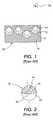
- FIG. 1depicts an enlarged section of rotating element sheet material 18 , including rotatable element 10 , enabling fluid 12 , cavity 14 , and substrate 16 . Observer 28 is also shown.
- FIG. 1depicts a spherically shaped rotatable element and cavity, many other shapes will work and are consistent with the present invention.
- the thickness of substrate 16may be of the order of hundreds of microns, and the dimensions of rotatable element 10 and cavity 14 may be of the order of 10 to 100 microns.
- substrate 16is an elastomer material, such as silicone rubber, that accommodates both enabling fluid 12 and the class of rotatable elements within a cavity or cavities disposed throughout substrate 16 .
- the cavity or cavitiescontain both enabling fluid 12 and the class of rotatable elements such that rotatable element 10 is in contact with enabling fluid 12 and at least one translational degree of freedom of rotatable element 10 is restricted.
- the contact between enabling fluid 12 and rotatable element 10breaks a symmetry of rotatable element 10 and allows rotatable element 10 to be addressed.
- the state of broken symmetry of rotatable element 10can be the establishment of an electric dipole about an axis of rotation.
- an electric dipolecan be established on a rotatable element in a dielectric liquid by the suitable choice of coatings applied to opposing surfaces of the rotatable element.
- rotating element sheet material 18as “reusable electric paper” is due to the fact that the rotatable elements are typically given a second broken symmetry, a multivalued aspect, correlated with the addressing polarity discussed above. That is, the above mentioned coatings may be chosen so as to respond to incident electromagnetic energy in distinguishable ways.
- the aspect of rotatable element 10 to observer 28 favorably situatedcan be controlled by an applied vector field.
- rotatable element 10may comprise a black polyethylene generally spherical body with titanium oxide sputtered on one hemisphere, where the titanium oxide provides a light-colored aspect in one orientation.
- a rotatable element in a transparent dielectric liquidwill exhibit the desired addressing polarity as well as the desired aspect.
- a multivalued aspect in its simplest formis a two-valued aspect.
- rotatable element 10 with a two-valued aspectcan be referred to as a bichromal rotatable element.
- Such a rotatable elementis generally fabricated by the union of two layers of material as described in U.S. Pat. No. 5,262,098, herein incorporated by reference.
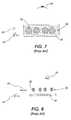
- FIGS. 2-4depict rotatable element 10 with a two-valued aspect and an exemplary system that use such rotatable elements.
- rotatable element 10is composed of first layer 20 and second layer 22 and is, by way of example again, a generally spherical body.
- the surface of first layer 20has first coating 91 at a first Zeta potential
- the surface of second layer 22has second coating 93 at a second Zeta potential.
- First coating 91 and second coating 93are chosen such that, when in contact with a dielectric fluid (not shown), first coating 91 has a net positive electric charge with respect to second coating 93 . This is depicted in FIG. 2 by the “+” and “ ⁇ ” symbols respectively.
- first coating 91 and the surface of first layer 20is non-white-colored, indicated in FIG. 2 by hatching, and the combination of second coating 93 and the surface of second layer 22 is white-colored.
- first layer 20 and first coating 91may be the same.
- second layer 22 and second coating 93may be the same.
- FIG. 3depicts no-field set 30 .
- No-field set 30is a subset of randomly oriented rotatable elements in the vicinity of vector field 24 when vector field 24 has zero magnitude.
- Vector field 24is an electric field.
- No-field set 30thus, contains rotatable elements with arbitrary orientations with respect to each other. Therefore, observer 28 in the case of no-field set 30 registers views of the combination of second coating 93 and the surface of second layer 22 , and first coating 91 and the surface of first layer 20 in an unordered sequence.
- Infralayer 26forms the backdrop of the aspect.
- Infralayer 26can consist of any type of material or aspect source, including but not limited to other rotatable elements or some material that presents a given aspect to observer 28 .
- FIG. 4depicts first aspect set 32 .
- First aspect set 32is a subset of rotatable elements in the vicinity of vector field 24 when the magnitude of vector field 24 is nonzero and has the orientation indicated by arrow 25 .
- all of the rotatable elementsorient themselves with respect to arrow 25 due to the electrostatic dipole present on each rotatable element 10 .
- observer 28 in the case of first aspect set 32registers a view of a set of rotatable elements ordered with the non-white-colored side up.
- infralayer 26forms the backdrop of the aspect.
- rotatable element 10under the influence of applied vector field 24 , orients itself with respect to vector field 24 due to the electric charges present as a result of first coating 91 and second coating 93 , as depicted in FIG. 2 .
- first aspect set 32will maintain its aspect after applied vector field 24 is removed, in part due to the energy associated with the attraction between rotatable element 10 and the substrate structure, as, for example, cavity walls (not shown). This energy contributes, in part, to the switching characteristics and the memory capability of rotating element sheet material 18 , as disclosed in U.S. Pat. No. 4,126,854, hereinabove incorporated by reference, and discussed in more detail below.
- a rotatable element with multivalued aspectis generally fabricated as disclosed in U.S. Pat. No. 5,919,409, herein incorporated by reference.
- An exemplary rotatable element 10 with multivalued aspectis depicted in FIG. 5 .
- Rotatable element 10 in FIG. 5is composed of first layer 36 , second layer 37 and third layer 38 .
- First layer 36 and third layer 38are transparent-clear to visible light and second layer 37 may be opaque or transparent-colored to visible light.
- third layer 38has third coating 95 at a first Zeta potential
- first layer 36has first coating 97 at a second Zeta potential such that third coating 95 has a net positive charge, “+,” with respect to first coating 97 when rotatable element 10 is in contact with a dielectric fluid (not shown).
- First coating 97 and third coating 95are also chosen to be transparent-clear to visible light. As above, one skilled in the art will appreciate that the material associated with first layer 36 and first coating 97 may be the same. Likewise, the material associated with third layer 38 and third coating 95 may be the same.
- Rotatable elements with multivalued aspectsare generally utilized in rotating element sheet material that uses canted vector fields for addressing.
- a canted vector fieldis a field whose orientation vector in the vicinity of a subset of rotatable elements can be set so as to point in any direction in three-dimensional space.
- U.S. Pat. No. 5,717,515, herein incorporated by referencediscloses the use of canted vector fields in order to address rotatable elements.
- the use of canted vector fields with rotating element sheet material 18allows complete freedom in addressing the orientation of a subset of rotatable elements, where the rotatable elements have the addressing polarity discussed above.
- An exemplary system that utilizes rotatable elements with three-valued aspects and a canted vector field for addressingis depicted in FIGS. 6-9.
- rotatable element 10 with a multivalued aspectis a “light valve,” as disclosed, for example, in U.S. Pat. No. 5,737,115, herein incorporated by reference and depicted in FIG. 5 .
- FIGS. 6 and 7depict first aspect set 72 .
- observer 28registers a coherent view of the face of the disk of opaque or transparent-color second layer 37 .
- First aspect set 72maximally obstructs infralayer 26 , where infralayer 26 can consist of any type of material or aspect source, including but not limited to other rotatable elements, or some material that presents a given aspect to observer 28 .
- FIG. 6is a side view indicating the relative positions of observer 28 , first aspect set 72 , and infralayer 26 .
- FIG. 7is an alternate view of first aspect set 72 from a top perspective. In FIG. 7, the symbol ⁇ indicates an arrow directed out of the plane of the figure.
- rotatable element 10under the influence of applied vector field 24 , orients itself with respect to vector field 24 due to the electric charges present as a result of first coating 97 and third coating 95 , as depicted in FIG. 5 .
- FIGS. 8 and 9depict second aspect set 76 of the system introduced in FIGS. 5-7.
- observer 28registers a coherent view of the disk of opaque or transparent-color second layer 37 edge-on.
- infralayer 26is minimally obstructed by the set of rotatable elements.
- FIG. 8is a side view indicating the relative positions of observer 28 , second aspect set 76 , and infralayer 26 .
- FIG. 9is an alternate view of second aspect set 76 from a top perspective.
- rotatable element 10under the influence of applied vector field 24 , orients itself with respect to vector field 24 due to the electric charges present as a result of first coating 97 and third coating 95 , as depicted in FIG. 5 .
- first aspect set 72 and second aspect set 76will maintain their orientation after applied vector field 24 is removed due to the energy associated with the attraction between rotatable element 10 and the substrate structure, as, for example, cavity walls (not shown). Again, this energy contributes, in part, to the switching characteristics and the memory capability of rotating element sheet material 18 , as disclosed in U.S. Pat. No. 4,126,854, hereinabove incorporated by reference and discussed in more detail below.
- no-field set, first aspect set, and second aspect set discussed above in FIGS. 3, 4 , and 6 - 9can form the elements of a pixel, where vector field 24 can be manipulated on a pixel by pixel basis using an addressing scheme as discussed, for example, in U.S. Pat. No. 5,717,515, hereinabove incorporated by reference.
- a useful property of rotating element sheet material 18is the ability to maintain a given aspect after the applied vector field 24 for addressing is removed. This ability contributes, in part, to the switching characteristics and the memory capability of rotating element sheet material 18 , as disclosed in U.S. Pat. No. 4,126,854, hereinabove incorporated by reference. This will be referred to as aspect stability.
- the mechanism for aspect stability in the above embodimentsis generally the energy associated with the attraction between the rotatable elements and the substrate structure, or “work function.”
- the applied vector field 24 for addressingmust be strong enough to overcome the work function in order to cause an orientation change; furthermore, the work function must be strong enough to maintain this orientation in the absence of an applied vector field 24 for addressing.
- FIG. 10depicts a subsection of rotating element sheet material 18 that includes first rotatable element 80 and second rotatable element 90 .
- FIG. 10depicts spherically shaped rotatable elements and cavities, many other shapes will work and are consistent with the present invention, as, for example, cylindrically shaped rotatable elements and cavities.
- Also shown in FIG. 10is enabling fluid 12 , first cavity wall 82 , second cavity wall 92 , substrate 16 , and surface 94 .
- first rotatable element 80 and second rotatable element 90are fabricated so as to exhibit different work functions. For example, as disclosed in U.S. Pat. No.
- a spherical rotatable element with a larger diameter and the same coatings as a spherical rotatable element with a smaller diametercan be shown to exhibit a higher work function.
- FIG. 10it is the interaction between first rotatable element 80 and first cavity wall 82 that gives rise to first work function.
- second rotatable element 90 and second cavity wall 92that gives rise to second work function.
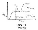
- FIG. 11depicts an exemplary graph of number 112 , N, of rotatable elements that change orientation as a function of applied vector field 24 , V, for rotating element sheet material 18 of FIG. 10 including a plurality of first rotatable elements 80 and a plurality of second rotatable elements 90 .
- First work function 124 , V w 1corresponds to the magnitude of applied vector field 24 when the number of first rotatable elements 80 and second rotatable elements 90 that change orientation has reached first saturation level 116 plus second saturation level 114 , N s 1 +N s 2 , corresponding to the orientation change of all first rotatable elements 80 and second rotatable elements 90 under the influence of applied vector field 24 .
- second work function 122corresponds to the magnitude of applied vector field 24 when the number of second rotatable elements 90 that change orientation has reached second saturation level 114 , N s 2 , corresponding to the orientation change of all second rotatable elements 90 only under the influence of applied vector field 24 .
- first rotatable elements 80only from the orientation depicted in FIG. 10 involves a two-step process.
- the first stepis indicated in FIG. 12 .
- vector field 24is applied in the direction of arrow 100 at first work function 124 .
- Thiscauses all of first rotatable elements 80 and second rotatable elements 90 to change orientation so that their addressing polarity aligns with the direction of the applied vector field 24 .
- FIG. 12In the context of the “light-valve” rotatable element discussed earlier, such an orientation corresponds to “closed” valves.
- vector field 24is applied in the direction of transverse arrow 110 at second work function 122 .
- Thiscauses all of second rotatable elements 90 to change orientation so that their addressing polarity aligns with the direction of the applied vector field 24 .
- Thisis depicted in FIG. 13 .
- the purpose of the second stepis to change the orientation of the second rotatable elements 90 back to the “open” orientation. This will be referred to as “highlight-erasing” the aspect associated with the second rotatable elements 90 .
- Second work function 122is applied in the direction of arrow 100 in order to change the orientation of second rotatable elements 90 only. This causes all of second rotatable elements 90 to change orientation so that their addressing polarity aligns with the direction of the applied vector field 24 .
- first rotatable element 80 that is initially in an “open” orientationremains in an open orientation.
- one or the other of the rotatable elementscan be selectively oriented for viewing by favorably situated observer 28 .
- first rotatable element 80 or second rotatable element 90The method of selectively orienting first rotatable element 80 or second rotatable element 90 only is surnmarized below in Table 1.
- Table 1the columns are divided according to applied vector field 24 at first work function 124 or applied vector field 24 at second work function 122 , and the columns are further subdivided according to whether the orientation of vector field 24 is in the general direction of observer 28 , indicated by the symbol ⁇ and corresponding to the direction of arrow 100 , or whether it is generally transverse to the direction of observer 28 , indicated by the symbol ⁇ and corresponding to the direction of transverse arrow 110 .
- the letter “Y”indicates that an applied field of magnitude suitable to overcome the appropriate work function is present in that particular orientation
- the letter “N”indicates that an applied field of magnitude not suitable to overcome the appropriate work function is present in that particular orientation.
- An additional column that indicates the number of steps necessary to obtain the desired aspect from a previous different aspectis also indicated.
- the row labeled “First Aspect”corresponds to the aspect and orientation depicted in FIG. 13, and the row labeled “Second Aspect” corresponds to the aspect and orientation depicted in FIG. 14 .
- the use of “Y-1st”indicates the first step of a two-step process, and the use of “Y-2nd” indicates the second step of a two-step process. For both rows, the starting orientation is that orientation depicted in FIG. 10 .
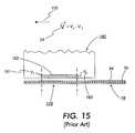
- FIG. 15depicts selective erasing system 180 that can be used to introduce vector field 24 in the direction of transverse arrow 110 through a subsection of rotating element sheet material 18 .
- selective erasing system 180contains potential drop implement 182 .
- one side of potential drop implement 182has a magnitude equal to first potential 181 , V 1
- the opposite side of potential drop implement 182has a magnitude equal to second potential 183 , V 2 .
- potential drop implement 182introduces vector field 24 throughout section 178 of the substrate of rotating element sheet material 18 in the direction of transverse arrow 110 .
- an erasing fieldis selectively introduced.
- the potential drop implement 182is preferably located at the distal end of selective erasing system 180 , where one side of distal end of selective erasing system 180 is determined by the location of first potential 181 and the opposite side of distal end of selective erasing system 180 is determined by the location of second potential 183 .
- FIG. 16Another erasing system is depicted in FIG. 16 and is also disclosed in U.S. Pat. No. 5,708,525, hereinabove incorporated by reference.
- positive electrode 184 and negative electrode 185are dispersed throughout rotating element sheet material 18 .
- the view depicted in FIG. 16is a top perspective of rotating element sheet material 18 .
- the dotted rectangular outlinedepicts rotating element sheet material 18 .
- Positive electrode 184 and negative electrode 185protrude outside of rotating element sheet material 18 , and extend within rotating element sheet material 18 beneath surface 94 in the example depicted in FIG. 16 .
- the magnitude of vector field 24is given by the potential difference, V, between positive electrode 184 and negative electrode 185 .
- vector field 24 of magnitude Vwill be oriented in the direction of transverse arrow 110 or transverse arrow 111 .
- substantially aspectis the aspect addressed at first work function 124 , excluding those aspects that can be addressed at lower values of the applied vector field 24 , and hence can be erased at lower values of the applied vector field 24 .
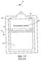
- addressing system 190disclosed in U.S. Pat. No. 5,389,945, herein incorporated by reference, and depicted in FIG. 17 can be a horizontal bar or wand which travels down surface 94 of rotating element sheet material 18 in the direction of arrow 130 and addresses all first rotatable elements 80 to create substantive aspect 160 .
- the exemplary rotating element sheet material 18 of FIG. 10is rotating element sheet material 18 of this discussion.
- Bottom surface 192which may comprise electrodes, interacts with addressing system 190 , which rides along top surface 94 of rotating element sheet material 18 , to introduce the appropriate vector field 24 at the appropriate location across addressing system 190 .
- addressing system 190which rides along top surface 94 of rotating element sheet material 18 , to introduce the appropriate vector field 24 at the appropriate location across addressing system 190 .
- FIG. 17the view in FIG. 17 is from a top perspective.
- rotating element sheet material 18can be highlight-erased at second work function 122 . Either of the erasure systems presented in FIGS. 15 or 16 can be used to introduce a suitable highlight-erasing field.
- a first embodiment of the present inventioncomprises a system of rotating element sheet material with reversible highlighting and a highlighting implement, where the rotating element sheet material with reversible highlighting is fabricated using two pluralities of rotatable elements.
- One plurality of rotatable elementsis addressed to present a first aspect associated with substantive aspect, and the second plurality of rotatable elements is addressed to present a second aspect associated with reversible highlighting.
- the highlighting implementis configured to selectively orient the second rotatable elements only using a first vector field.
- a second embodiment of the present inventioncomprises a system of rotating element sheet material with reversible highlighting and a highlighting implement, where the rotating element sheet material with reversible highlighting is fabricated using three pluralities of rotatable elements, where one plurality of rotatable elements is addressed to present a first aspect associated with substantive aspect, the second plurality of rotatable elements is addressed to present a second aspect associated with a first reversible highlighting, and the second and third rotatable elements together are addressed to present a third aspect associated with a second reversible highlighting.
- the highlighting implementis configured to either selectively orient the second rotatable elements only using a first vector field in a first direction, or selectively orient both the second rotatable elements and the third rotatable elements using a second vector field in a first direction.
- Another embodiment of the present inventioncomprises the first embodiment system described above, further comprising an erasing implement, where the erasing implement is configured to selectively orient the second rotatable elements only using a second vector field.
- a further embodiment of the present inventioncomprises the second embodiment system described above, further comprising an erasing implement, where the erasing implement is configured to either selectively orient the second rotatable elements only using the first vector field in a second direction or selectively orient both the second rotatable elements and the third rotatable elements using the second vector field in a second direction.
- a kitcomprises the first embodiment system described above, an erasing implement, and a binder, where the erasing implement is configured to selectively orient the second rotatable elements only using a second vector field, and the binder is configured to accommodate the first embodiment system and the erasing implement.
- a kitcomprises the second embodiment system described above, an erasing implement, and a binder, where the erasing implement is configured to either selectively orient the second rotatable elements only using the first vector field in a second direction or selectively orient both the second rotatable elements and the third rotatable elements using the second vector field in a second direction, and the binder is configured to accommodate the second embodiment system and the erasing implement.
- a first embodiment of a method of use consistent with the present inventioncomprises: providing the first embodiment system above; providing an erasing implement, where the erasing implement is configured to selectively orient the second rotatable elements only using a second vector field; applying the highlighting implement to a first region of the rotating element sheet material with reversible highlighting to selectively orient the second rotatable elements only; and applying the erasing implement to a portion of the first region of the rotating element sheet material with reversible highlighting to selectively orient the second rotatable elements only.
- a second embodiment of a method of use consistent with the present inventioncomprises: providing the second embodiment system above; providing an erasing implement, where the erasing implement is configured to either selectively orient the second rotatable elements only using the first vector field in a second direction or selectively orient both the second rotatable elements and the third rotatable elements using the second vector field in a second direction; applying the highlighting implement to a first region of the rotating element sheet material with reversible highlighting to selectively orient the second rotatable elements only, or both the second rotatable elements and the third rotatable elements; and applying the erasing implement to a portion of the first region of the rotating element sheet material with reversible highlighting to selectively orient the second rotatable elements only, or both the second rotatable elements and the third rotatable elements.
- FIG. 1depicts an exemplary subsection of rotating element sheet material of the prior art.
- FIG. 2depicts an exemplary rotatable element of the prior art with a two-valued aspect.
- FIG. 3depicts an exemplary system of the prior art that uses rotatable elements with two-valued aspects randomly oriented in the presence of an addressing vector field with zero magnitude.
- FIG. 4depicts the exemplary system of FIG. 3 in the presence of a non-zero addressing vector field.
- FIG. 5depicts an exemplary rotatable element of the prior art with a multivalued aspect.
- FIG. 6depicts a side view of an exemplary system of the prior art that uses rotatable elements with multivalued aspects in the presence of a canted vector field in a first direction for addressing.
- FIG. 7depicts an alternate view of the exemplary system of FIG. 6 .
- FIG. 8depicts the exemplary system of FIG. 6 in the presence of a canted vector field in a second direction for addressing.
- FIG. 9depicts an alternate view of the exemplary system of FIG. 8 .
- FIG. 10depicts an exemplary subsection of rotating element sheet material of the prior art with a first rotatable element and a second rotatable element.
- FIG. 11depicts an exemplary graph of the number of rotatable elements that change orientation as a function of applied vector field of the prior art, displaying work function and saturation numbers for the rotating element sheet material of FIG. 10 .
- FIG. 12depicts an exemplary subsection of rotating element sheet material of the prior art with a first rotatable element and a second rotatable element and an addressing vector field at a first work function.
- FIG. 13depicts an exemplary subsection of rotating element sheet material of the prior art with a first rotatable element and a second rotatable element and an erasing vector field at a second work function.
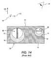
- FIG. 14depicts an exemplary subsection of rotating element sheet material of the prior art with a first rotatable element and a second rotatable element and an addressing field at a second work function.
- FIG. 15depicts an exemplary selective-erasing implement of the prior art.
- FIG. 16depicts an exemplary bulk-erasing system of the prior art.
- FIG. 17depicts an addressing implement of the prior art.
- FIG. 18depicts an exemplary first rotatable element consistent with the present invention.
- FIG. 19depicts an exemplary second rotatable element consistent with the present invention.
- FIG. 20depicts a first exemplary subsection of rotating element sheet material with reversible highlighting using the rotatable elements of FIGS. 18 and 19.
- FIG. 21depicts an alternate view of the exemplary system of FIG. 20 .
- FIG. 22is an exemplary circuit diagrarn associated with a reversible highlighting implement.
- FIG. 23depicts an exemplary reversible highlighting implement consistent with the present invention and a substantive aspect to be highlighted.
- FIG. 24depicts a reversible highlighting implement and a highlighted aspect of the system of FIG. 23 .
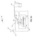
- FIG. 25depicts an exemplary reversible highlighting implement and a highlighted aspect to be selectively erased consistent with the present invention.
- FIG. 26depicts an exemplary highlighting implement and a highlighted aspect selectively erased of the system of FIG. 25 .
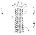
- FIG. 27depicts a cross section of an exemplary two-sided sheet of rotating element sheet material with reversible highlighting.
- FIG. 28depicts an exemplary rotatable element consistent with the present invention.
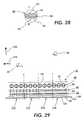
- FIG. 29depicts a second exemplary subsection of rotating element sheet material with reversible highlighting using the rotatable elements depicted in FIGS. 18, 19 , and 28 .
- FIG. 30depicts an exemplary graph of the number of rotatable elements that change orientation as a function of applied vector field, displaying work function and saturation numbers for a the rotating element sheet material of FIG. 29 .
- FIG. 31depicts an alternate view of the exemplary system of FIG. 29 .
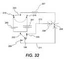
- FIG. 32is a second exemplary circuit diagram associated with a reversible highlighting implement.
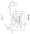
- FIG. 33depicts a second exemplary reversible highlighting implement consistent with the present invention and a substantive aspect to be highlighted.
- FIG. 34depicts the second reversible highlighting implement and a highlighted aspect of the system of FIG. 33 .
- FIG. 35depicts a second exemplary reversible highlighting implement and a highlighted aspect to be selectively erased consistent with the present invention.
- FIG. 36depicts the second exemplary reversible highlighting implement and a highlighted aspect selectively erased of the system of FIG. 35 .
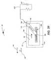
- FIG. 37depicts a second exemplary reversible highlighting implement consistent with the present invention and a substantive aspect to be highlighted.
- FIG. 38depicts the second exemplary reversible highlighting implement and a highlighted aspect of the system of FIG. 37 .
- FIG. 39depicts a second exemplary reversible highlighting implement and a highlighted aspect to be selectively erased consistent with the present invention.
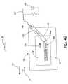
- FIG. 40depicts the second exemplary reversible highlighting implement and a highlighted aspect selectively erased of the system of FIG. 39 .
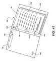
- FIG. 41depicts an exemplary course pack of reversible highlighting rotatable element sheet material with a reversible highlighting implement.
- aspectsrefers to a common response to incident electromagnetic energy of interest. For example, if the incident electromagnetic energy of interest lies in the visible spectrum, then a first aspect can correspond to a black appearance, and a second aspect can correspond to a white appearance. If the incident electromagnetic energy of interest lies in the x-ray region, then a first aspect can correspond to the transmission of the x-ray energy, while a second aspect can correspond to the absorption of the x-ray energy.
- the “common response”can comprise of any of the phenomena of absorption, reflection, polarization, transmission, fluorescence or any combination thereof.
- observerrefers to a human perceiver, or to a human perceiver in conjunction with an apparatus sensitive to the electromagnetic energy of interest. If the electromagnetic energy of interest lies in the visible spectrum, then observer can refer to a human perceiver. If the electromagnetic energy of interest lies outside of the visible spectrum, then observer refers to an apparatus sensitive to the electromagnetic energy and capable of resolving the aspects of interest into human perceivable form.
- vector fieldrefers to a field whose amplitude in space is capable of having a magnitude and a direction.
- Vector fields of interest in the present inventioninclude electric fields, magnetic fields, or electromagnetic fields.
- work functionrefers to the amount of energy necessary to overcome the attraction between a rotatable element and the substrate structure so as to enable a change of orientation, as for example, between the rotatable element and the cavity walls.
- a host of factorsinfluence the magnitude of the energy associated with the work function including, but not limited to: surface tension of enabling fluid in contact with rotatable elements; the relative specific gravity of enabling fluid and rotatable element; magnitude of charge on rotatable element; relative electronic permittivity of enabling fluid and substrate structure; “stickiness” of substrate structure; and other residual vector fields that may be present.
- substantially aspectrefers to the aspect associated with the information conveyed to the observer that is only addressable and only erasable at a work function that is high relative to the work function associated with the “highlighted aspect” (defined below).
- “highlighted aspect”refers to an aspect that distinguishes substantive material (as defined above) for an observer, usually for later reference, and that is addressable and erasable at a work function that is low relative to the work function associated with the “substantive aspect.”
- a first aspect“saturates” a second aspect when the union of the first aspect and the second aspect is a third aspect that is indistinguishable, or distinguishable only slightly from the first aspect.
- a transparent orange-colored aspectsaturates a transparent yellow-colored aspect.
- highlight-addressand “highlight-erase” refer to the vector fields necessary to present a highlighted aspect or a non-highlighted aspect respectively for the rotatable element addressable at the work function that is low relative to the work function associated with “substantive aspect” defined above.
- address and “erase”refer to the vector fields at the work function that is high relative to the work function associated with “highlighted aspect” defined above.
- transparent-clearrefers to an aspect associated with an orientation of a rotatable element such that all or most of the incident electromagnetic energy of interest is transmitted.
- transparent-coloredrefers to an aspect associated with an orientation of a rotatable element such that a subset of the incident electromagnetic energy of interest is transmitted and a subset of the incident electromagnetic energy of interest is reflected and/or absorbed.
- opaquerefers to an aspect associated with an orientation of a rotatable element such that all or most of the incident electromagnetic energy of interest is reflected and/or absorbed.
- non-transparent-clearencompasses both “transparent-colored” and “opaque.”
- open and closedrefer to the orientation of light-valve-type rotatable elements such that a favorably situated observer is presented with transparent-clear aspect or a non-transparent-clear aspect respectively.
- diameterrefers to an order of magnitude dimension corresponding to any of height, width, and depth of any of rotatable elements or cavities. The use of “diameter” does not imply that circular or spherical geometry only is under consideration.
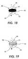
- FIGS. 18 and 19Rotatable elements consistent with a preferred embodiment of the present invention are depicted in FIGS. 18 and 19.
- FIG. 18depicts first rotatable element 40
- FIG. 19depicts second rotatable element 50 .
- Both first rotatable element 40 and second rotatable element 50are fabricated as “light-valves” as previously depicted in the systems of FIGS. 5-10, and 12 - 14 .
- first layer 41is transparent-clear and third layer 43 is transparent-clear. Furthermore, the surface of third layer 43 has transparent-clear third coating 45 at a first Zeta potential, and the surface of first layer 41 has transparent-clear first coating 44 at a second Zeta potential such that the surface of third layer 43 has a net positive charge, “+,” with respect to the surface of first layer 41 when rotatable element 40 is in contact with a dielectric fluid (not shown).
- second layer 42 of first rotatable element 40is opaque to visible light and presents a dark-colored aspect when it is in a “closed” orientation.
- Second rotatable element 50is depicted in FIG. 19 .
- first layer 51is transparent-clear and third layer 53 is transparent-clear.
- the surface of third layer 53has transparent-clear third coating 55 at a first Zeta potential
- the surface of first layer 51has transparent-clear first coating 54 at a second Zeta potential such that the surface of third layer 53 has a net positive charge, “+,” with respect to the surface of first layer 51 when rotatable element 50 is in contact with a dielectric fluid (not shown).
- second layer 52 of second rotatable element 50is transparent-colored to visible light and presents a light-colored aspect when it is in a “closed” orientation.
- the transparent color associated with second rotatable element 50 in a preferred embodimentis a color associated with conventional highlighters, such as yellow, pink, orange, or other colors.
- conventional highlighterssuch as yellow, pink, orange, or other colors.
- opaque segmentsmay also be used in the second rotatable elements 50 , the visual appearance of the resulting display will be less like that of a conventional highlighter than would be the case with transparent-colored center segments on dark-colored text and graphics and a light-colored background.
- Rotating element sheet material 70 with reversible highlightingis depicted in FIGS. 20 and 21.
- FIGS. 20 and 21there is a plurality of first rotatable elements 40 in first layer 46 , and a plurality of second rotatable elements 50 in second layer 56 .
- First rotatable elements 40have common aspects, as well as a common first work function 124 .
- second rotatable elements 50have common aspects, as well as a common second work function 122 .
- the graph of FIG. 11, discussed earlier,is an exemplary graph of first work function 124 and second work function 122 associated with rotating element sheet material 70 of FIGS.
- FIG. 20is a side perspective and FIG. 21 is a top perspective view.
- FIG. 21is a top perspective view.
- FIG. 21For ease of depiction in FIG. 21, only those rotatable elements in a “closed” orientation from FIG. 20 are shown. Rotatable elements in an “open” orientation from FIG. 20 are not shown in FIG. 21 .
- the symbol ⁇indicates an arrow directed out of the plane of the figure.
- first rotatable elements 40are in first layer 46
- second rotatable elements 50are in second layer 56
- both first layer and second layerare between infralayer 26 and observer 28 .
- Surface 94lies between observer 28 and first rotatable elements 40 and second rotatable elements 50 .
- Infralayer 26in a preferred embodiment of the present invention, is a light-colored reflective material. It will be appreciated by one skilled in the art that although FIG. 20 depicts ordered layers of rotatable elements, in practice, such plurality of rotatable elements can be distributed randomly through the substrate and a similar effect will be achieved.
- First rotatable elements 40can be rotated to expose or to conceal the light-colored infralayer, thus producing the visual effect of either a light-colored aspect, or a dark-colored aspect.
- first rotatable elements 40provide the aspect associated with the substantive material. This is depicted in FIG. 21 by the solid black circles.
- First rotatable elements 40exhibit first work function 124 of FIG. 11, which is higher than second work function 122 associated with second rotatable elements 50 .
- One manner of establishing this differenceis to use first rotatable elements 40 with a larger diameter than second rotatable elements 50 .
- spheroidal rotatable elements with a larger diameterwill exhibit a higher threshold for changing orientation due to a larger moment of inertia.
- first rotatable elements 40are larger in diameter than the second rotatable elements 50 , then first rotatable elements 40 will have a higher work function than second rotatable elements 50 .
- FIG. 11depicts an exemplary set of work functions associated with rotating element sheet material 70 of FIGS. 20 and 21.
- First work function 124 , V W 1represents the threshold necessary to address both first saturation level 116 , N W 1 , of first rotatable elements 40 and second saturation level 114 , N W 2 , of second rotatable elements 50 ;
- second work function 122 , V W 2represents the threshold necessary to address second saturation level 114 , N W 2 , of second rotatable elements 50 only.
- region 170 , region 172 , region 174 , and region 176depict regions of rotating element sheet material 70 that have been placed under the influence of separate vector fields for addressing purposes. This can be accomplished through the use of addressing implement 190 as depicted in FIG. 17, as well as through the use of a reversible highlighting implement as described below.
- each regionis initially erased through the application of vector field 24 at first work function 124 in the direction of transverse arrow 110 .
- region 170no further vector field is applied.
- observer 28views all of first rotatable elements 40 and second rotatable elements 50 edge on. Because both first rotatable elements 40 and second rotatable elements 50 function as “light valves,” observer 28 views a transparent-clear aspect associated with this configuration.
- observer 28views infralayer 26 , which is a light-colored reflective layer as shown in FIG. 21 .
- first work function 124is applied in the direction of arrow 100 and then second work function 122 is applied in the direction of transverse arrow 110 .
- observer 28views all of first rotatable elements 40 in a “closed” state, and all of second rotatable elements 50 in an “open” state.
- Observer 28views a dark-colored aspect associated with this configuration and no highlighted aspect, as depicted in FIG. 21 .
- second work function 122is applied in the direction of arrow 100 only.
- observer 28views all of first rotatable elements 40 edge on, and all of and second rotatable elements 50 in a closed state.
- Observer 28views a infralayer 26 with a highlighted aspect, as depicted in FIG. 21 .
- first work function 124is applied in the direction of arrow 100 only.
- observer 28views all of first rotatable elements 40 and second rotatable elements 50 in a closed state.
- Observer 28views a highlighted dark aspect, as depicted in FIG. 21 .
- first rotatable element 40 or second rotatable element 50The method of selectively orienting first rotatable element 40 or second rotatable element 50 only is summarized below in Table 2.
- Table 2the columns are divided according to applied vector field 24 at first work function 124 or applied vector field 24 at second work function 122 , and the columns are further subdivided according to whether the orientation of vector field 24 is in the general direction of observer 28 , indicated by the symbol ⁇ and corresponding to the direction of arrow 100 , or whether it is generally transverse to the direction of observer 28 , indicated by the symbol ⁇ and corresponding to the direction of transverse arrow 110 .
- the letter “Y”indicates that an applied field of magnitude suitable to overcome the appropriate work function is present in that particular orientation
- the letter “N”indicates that an applied field of magnitude not suitable to overcome the appropriate work function is present in that particular orientation.
- An additional columnthat indicates the number of steps necessary to obtain the desired aspect from a previous different aspect is also indicated.
- the rowsare subdivided according to region 172 , region 174 , and region 176 of FIGS. 20 and 21.
- the use of “Y-1st”indicates the first step of a two-step process, and the use of “Y-2nd” indicates the second step of a two-step process. For all rows, the starting orientation is that orientation depicted in region 170 of FIGS. 20 and 21.
- the plurality of first rotatable elements 40 dispersed throughout an exemplary sheet of rotating element sheet material with reversible highlighting 70are addressed to present a substantive aspect using an applied vector field at first work function 124 . Since, in the embodiment discussed here, this would also address a plurality of second rotatable elements 50 , the entire sheet should be put under the influence of an applied vector field at a second work function 122 in the direction of transverse arrow 110 or transverse arrow 111 discussed earlier, or a highlight-erase field. This will reorient the plurality of second rotatable elements 50 into an highlight-erased orientation.
- the highlight-erase fieldcan be introduced by using selective-erasure system 180 of FIG.
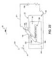
- FIG. 22An exemplary circuit diagram associated with such a reversible highlighting implement is depicted in FIG. 22 .
- Toggle 202can be manipulated by a user to be in off position 199 , highlight-address position 204 , or highlight-erase position 205 .
- the elements of the circuit depicted in FIG. 22include power source 200 , exemplary resistance 207 , and the capacitors associated with gap 208 or 209 .
- Gap 208corresponds to the gap introduced by potential drop implement 182 depicted in FIG. 15 of selective-erasing system 180 and that spans region 178 .
- toggle 202 in highlight-erase position 205closes highlight-erase circuit 212 associated with an implement for selective highlight-erasure.
- Gap 209corresponds to the gap between surface 94 of rotating element sheet material with reversible highlighting 70 and conducting layer 105 as depicted in FIG. 20 .
- the combination of toggle 202 in highlight-address position 204 and the distal end of reversible highlighting implement applied to surface 94 of rotating element sheet material with reversible highlighting 70closes highlight-address circuit 211 associated with an implement for selective highlight-addressing.
- rotating element sheet materialis prepared containing substantive material 160 with all of second rotatable elements 40 in a highlight-erase orientation, or “open,” as depicted, for example in region 170 and 172 respective.
- reversible highlighting implement 162can be manipulated by a user such that distal end 168 is dragged across surface 94 of rotating element sheet material 70 . This is depicted in FIGS. 23 and 24.
- Reversible highlighting implement 162can operate at second work function 122 and can introduce vector field 24 in the direction of arrow 100 .
- Toggle 163 in FIGS. 23 and 24 in the position indicated by the symbol “I”corresponds to toggle 202 of FIG. 22 in highlight-address position 204 .
- Toggle 163 in FIGS. 23 and 24 in the position indicated by the symbol “O”corresponds to toggle 202 of FIG. 22 in off position 199 .
- Toggle 163 in FIGS. 23 and 24 in the position indicated by the symbol “X”corresponds to toggle 202 of FIG. 22 in highlight-erase position 205 .
- FIG. 23displays substantive aspect 160 as it might be presented to observer 28 before the application of reversible highlighting implement 162
- FIG. 24displays substantive plus highlighted aspect 164 after reversible highlighting implement 162 has been dragged across in the direction of arrow 130 with toggle 163 in highlight-address position, denoted by an “I.”
- Connector 166is a connection from reversible highlighting implement 162 to first power source 200 of highlight-address circuit 211 .
- connector 106is a connection from conducting layer 105 to first power source 200 of highlight-address circuit 211 .
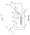
- rotating element sheet materialis prepared containing substantive material 160 with some of second rotatable elements 50 in a “closed” orientation.
- reversible highlighting implement 162 with toggle 163 set in highlight-erase positiondenoted by an “X” in FIG. 25, can be manipulated by a user such that it is dragged across surface 94 of rotating element sheet material 70 in order to have selective highlight-erasure. This is depicted in FIGS. 25 and 26.
- Reversible highlighting implement 162 in highlight-erase modefunctions as selective erasure implement 180 as depicted in FIG. 15 and using highlight-erase circuit 212 depicted in FIG. 22 .
- reversible highlighting implement 162does not change the aspect presented to observer 28 associated with first rotatable elements 40 even though it does change the aspect presented to observer 28 associated with second rotatable elements 50 .
- FIG. 25displays highlighted material 164 as it might be presented to observer 28 before the application of reversible highlighting implement 162
- FIG. 26displays substantive material plus selective highlight-erase aspect 165 after reversible highlighting implement 162 has been dragged across a portion of the highlighted area.
- Connector 166is a connection from reversible highlighting implement 162 to power source 200 of highlight-erase circuit 212 .
- the rotating element sheet material with reversible highlightingis fabricated so as to function on both sides of rotating element sheet material, as taught, for example in U.S. Pat. No. 5,723,204, herein incorporated by reference.
- An exemplary cross section of such rotating element sheet material 140is depicted in FIG. 27 .
- first observer 28 and second observer 29are also shown in FIG. 27 .
- Surface 94lies between first observer 28 and first layer 46 and second layer 56 .
- Infralayer 26forms the backdrop of the aspect presented to first observer 28 and conducting layer 105 lies below infralayer 26 .
- Connector 106can connect between conducting layer 105 and a power source (not shown).
- conducting layer 105On the opposite side of conducting layer 105 is the corresponding second infralayer 27 third layer 57 , fourth layer 47 and surface 96 , where such elements, in the depicted cross-section plane, are the corresponding mirror-image elements to infralayer 26 , second layer 46 , first layer 46 and surface 94 , respectively.
- a reversible highlighting implement(not shown) may be applied to surface 94 to influence the orientation second rotatable elements in second layer 56 .
- surface 96in order to influence the orientation of second rotatable elements in third layer 57 .
- Conducting layer 105serves both as a pole of the capacitor corresponding to gap 209 of FIG. 22, and also as a shield of vector fields between the regions separated by conducting layer 105 .
- vector fields introduced along surface 94are shielded from affecting the region between surface 96 and infralayer 27 due to conducting layer 105 .
- vector fields introduced along surface 96are shielded from affecting the region between surface 94 and infralayer 26 , also due to conducting layer 105 .
- one or the other side of the rotating element sheet material with reversible highlighting 140 of FIG. 27may be selectively addressed, erased, highlight-addressed, and highlight-erased.
- FIGS. 18, 19 , and 28Rotatable elements consistent with another preferred embodiment of the present invention are depicted in FIGS. 18, 19 , and 28 .
- FIG. 18depicts first rotatable element 40
- FIG. 19depicts second rotatable element 50
- FIG. 28depicts third rotatable element 60 .
- First rotatable element 40 , second rotatable element 50 , and third rotatable element 60are all fabricated as “light-valves,” as previously depicted in the systems of FIGS. 5-10, and 12 - 14 .
- first layer 41is transparent-clear and third layer 43 is transparent-clear. Furthermore, the surface of third layer 43 has transparent-clear third coating 45 at a first Zeta potential, and the surface of first layer 41 has transparent-clear first coating 44 at a second Zeta potential such that the surface of third layer 43 has a net positive charge, “+,” with respect to the surface of first layer 41 when rotatable element 40 is in contact with a dielectric fluid (not shown).
- second layer 42 of first rotatable element 40is opaque to visible light and presents a dark-colored aspect when it is in a “closed” orientation.
- Second rotatable element 50is depicted in FIG. 19 .
- first layer 51is transparent-clear and third layer 53 is transparent-clear.
- the surface of third layer 53has transparent-clear third coating 55 at a first Zeta potential
- the surface of first layer 51has transparent-clear first coating 54 at a second Zeta potential such that the surface of third layer 53 has a net positive charge, “+,” with respect to the surface of first layer 51 when rotatable element 50 is in contact with a dielectric fluid (not shown).
- second layer 52 of second rotatable element 50is transparent-colored to visible light and presents a light-colored aspect when it is in a “closed” orientation.
- the transparent color associated with second rotatable elements 50 in a preferred embodimentis a color associated with conventional highlighters, such as yellow, pink, orange, or other colors.
- conventional highlighterssuch as yellow, pink, orange, or other colors.
- opaque segmentsmay also be used in the second rotatable elements 50 , the visual appearance of the resulting display will be less like that of a conventional highlighting marker than would be the case with transparent-color center segments on dark-colored text and graphics and a light-colored background.
- Third rotatable element 60is depicted in FIG. 28 .
- first layer 61is transparent-clear and third layer 63 is transparent-clear.
- the surface of third layer 63has transparent-clear third coating 65 at a first Zeta potential
- the surface of first layer 61has transparent-clear first coating 64 at a second Zeta potential such that the surface of third layer 63 has a net positive charge, “+,” with respect to the surface of first layer 61 when rotatable element 60 is in contact with a dielectric fluid (not shown).
- second layer 62 of third rotatable element 60is transparent-colored to visible light and presents a light-colored aspect when it is in a “closed” orientation.
- the transparent color associated with third rotatable elements 60 in a preferred embodimentis a second color associated with conventional highlighters, such as yellow, pink, orange, or other colors, and is distinguishable from the transparent color of second rotatable element 50 .
- conventional highlighterssuch as yellow, pink, orange, or other colors
- the transparent color of third rotatable elements 60may be chosen so as to saturate the transparent color of second rotatable element 50 .
- Rotating element sheet material 74 with reversible highlighting utilizing first rotatable element 40 , second rotatable element 50 , and third rotatable element 60is depicted in FIGS. 29 and 31.
- first rotatable elements 40there is a plurality of first rotatable elements 40 , a plurality of second rotatable elements 50 , and a plurality of third rotatable elements 60 .
- first rotatable elements 40have the same first aspects, as well as a common first work function 124 .
- second rotatable elements 50have the same second aspects, as well as a common second work function 122 .
- third rotatable elements 60have the same third aspects, as well as a common third work function 126 .
- the graph of FIG. 30is an exemplary graph of first work function 124 , second work function 122 , and third work function 126 associated with rotating element sheet material 74 of FIGS. 29 and 31. For ease of depiction in FIG. 31, only those rotatable elements in a “closed” orientation from FIG. 29 are shown. Rotatable elements in an “open” orientation from FIG. 29 are not shown.
- first rotatable elements 40are in first layer 46
- second rotatable elements 50are in second layer 56
- third rotatable elements 60are in third layer 66
- all of first layer, second layer, and third layerare between infralayer 26 and observer 28 .
- surface 94lies between observer 28 and any of first rotatable element 40 , second rotatable element 50 , and third rotatable element 60 .
- Infralayer 26in a preferred embodiment of the present invention, is a light reflective material. It will be appreciated by one skilled in the art that although FIG.
- FIGS. 29 and 31depicts ordered layers of rotatable elements, in practice, such plurality of rotatable elements can be distributed randomly through the substrate, and the same view will be achieved.
- FIGS. 29 and 31depicts merely a preferred ordering since it presents a maximal configuration of rotatable elements to aspect area.
- Such an “eggcrate” configurationfor example, is disclosed in U.S. Pat. No. 5,815,306, hereinabove incorporated by reference.
- first rotatable elements 40can be rotated to expose or to conceal the light-colored infralayer, thus producing the visual effect of either a light-colored aspect, or a dark-colored aspect.
- first rotatable elements 40provides the aspect associated with the substantive aspect.
- First rotatable elements 40have a first work function 124 of FIG. 30, which is higher than second work function 122 associated with second rotatable elements 50 , and third work function 126 associated with third rotatable elements 60 .
- One manner of establishing the difference of work functionsis to vary the diameter of the rotatable elements as described earlier.
- FIG. 30depicts an exemplary set of work functions associated with rotating element sheet material 74 of FIGS. 29 and 31.
- First work function 124V W 1 , represents the threshold necessary to address all of first saturation level 116 , V W 1 , of first rotatable elements 40 , second saturation level 114 , V W 2 , of second rotatable elements 50 , and third saturation level 118 , V W 3 , of third rotatable elements 60 ;
- second work function 122 , V W 2represents the threshold necessary to address both second saturation level 114 , V W 2 , of second rotatable elements 50 and third saturation level 118 , V W 3 , of third rotatable elements 60 ;
- third work function 126 , V W 3represents the threshold necessary to address the third saturation level 118 , V W 3 , of third rotatable elements 60 only.
- region 170 , region 172 , region 174 , and region 176depict regions of rotating element sheet material 74 that have been placed under the influence of separate vector fields for addressing purposes. This can be accomplished through the use of an addressing implement 190 as depicted in FIG. 17, as well as through the use of a reversible highlighting implement as described below.
- each regionis initially erased through the application of vector field 24 in the direction of transverse arrow 110 .
- observer 28views all of first rotatable elements 40 , second rotatable elements 50 , and third rotatable elements 60 edge on.
- first rotatable elements 40second rotatable elements 50 , and third rotatable elements 60 function as “light valves”
- observer 28views a transparent-clear aspect associated with this configuration.
- observer 28views infralayer 26 , which is a light-reflective layer, as depicted in FIG. 31 .
- observer 28views all of first rotatable elements 40 in a closed orientation, all of second rotatable elements 50 in an open orientation, and all of third rotatable elements 60 in a closed orientation.
- observer 28views a dark-colored aspect associated with this configuration and highlighted aspect associated with third rotatable elements 60 .
- a highlighted aspectmay be associated with the highlight color yellow.
- observer 28views all of first rotatable elements 40 in an open orientation, all of second rotatable elements 50 in a closed orientation, and all of third rotatable elements 60 in a closed orientation.
- observer 28views infralayer 26 in a highlighted state and no dark-colored aspect. In this case, and in the preferred embodiment discussed above, such a highlighted aspect may be associated with the highlight color orange.
- observer 28views all of first rotatable elements 40 , second rotatable elements 50 , and third rotatable elements 60 in a closed orientation.
- observer 28views a highlighted dark aspect, where the highlighted aspect is associated with the color orange in the preferred embodiment discussed above.
- the method of selectively orienting first rotatable element 40 , third rotatable element 60 only, or both second rotatable element 50 and third rotatable element 60is summarized below in Table 3.
- Table 3the columns are divided according to applied vector field 24 at first work function 124 , applied vector field 24 at second work function 122 , or applied vector field 24 at third work function 126 and the columns are further subdivided according to whether the orientation of vector field 24 is in the general direction of observer 28 , indicated by the symbol ⁇ and corresponding to the direction of arrow 100 , or whether it is generally transverse to the direction of observer 28 , indicated by the symbol ⁇ and corresponding to the direction of transverse arrow 110 .
- the letter “Y”indicates that an applied field of magnitude suitable to overcome the appropriate work function is present in that particular orientation
- the letter “N”indicates that an applied field of magnitude not suitable to overcome the appropriate work function is present in that particular orientation.
- An additional columnthat indicates the number of steps necessary to obtain the desired aspect from a previous different aspect is also indicated.
- the rowsare subdivided according to region 172 , region 174 , and region 176 of FIGS. 29 and 31.
- the use of “Y-1st”indicates the first step of a two-step process, the use of “Y-2nd” indicates the second step of a two-step process, and the use of “Y-3rd”. For all rows, the starting orientation is that orientation depicted in region 170 of FIGS. 29 and 31.
- the plurality of first rotatable elements 40 dispersed throughout an exemplary sheet of rotating element sheet material with reversible highlighting 74are addressed to present a substantive aspect using an applied vector field at first work function 124 . Since, in the embodiment discussed here, this would also highlight-address the plurality of second rotatable elements 50 and third rotatable elements 60 , the entire sheet should be put under the influence of an applied vector field at a second work function 122 in the direction of transverse arrow 110 or another suitable transverse direction as discussed earlier. This will reorient the plurality of second rotatable elements 50 and the plurality of third rotatable elements 60 into an highlight-erased orientation.
- the highlight-erasure fieldcan be introduced by using selective-erasure system 180 of FIG. 15, or the bulk-erasure system of FIG. 16 discussed earlier.
- the userthen, with a reversible highlighting implement, can selectively highlight-address second rotatable elements 50 or both second rotatable elements 50 and third rotatable elements 60 , and may also selectively highlight-erase second rotatable elements 50 or both second rotatable elements 50 and third rotatable elements 60 with a reversible highlighting implement.
- An exemplary circuit diagram associated with such a reversible highlighting implementis depicted in FIG. 32 .
- Toggle 202can be manipulated by a user to be in off position 199 , highlight-address position 204 , or highlight-erase position 205 .
- Toggle 203can be manipulated by a user in first power source position 215 or second power source position 216 .
- the elements of the circuit depicted in FIG. 32include first power source 200 , second power source 201 , exemplary resistance 207 , and the capacitors associated with gap 208 or 209 .
- Gap 208corresponds to the gap introduced by potential drop implement 182 depicted in FIG. 15 of selective-erasing system 180 .
- toggle 202 in highlight-erase position 205closes highlight-erasing circuit 212 associated with an implement for selective highlight erasure.
- Circuit 212may include first power source 200 or second power source 201 depending upon the position of toggle 203 .
- Gap 209corresponds to the gap between surface 94 of rotating element sheet material with reversible highlighting 74 and conducting layer 105 as depicted in FIG. 29 .
- the combination of toggle 202 in highlight position 204 and the distal end of reversible highlighting implement applied to surface 94 of rotating element sheet material with reversible highlighting 74closes highlight-address circuit 211 associated with an implement for selective highlight-addressing.
- highlight-address circuit 211may include first power source 200 or second power source 201 depending upon the position of toggle 203 .
- rotating element sheet materialis prepared containing substantive aspect with all of the second rotatable elements 50 and third rotatable elements 60 in an open orientation.
- a usercan manipulate highlighting implement 142 such that it is dragged across surface 94 of rotating element sheet material 74 . This is depicted in FIGS. 33 and 34.
- Highlighting implement 142in this case operates at third work function 126 . As described above, highlighting implement introduces a vector field in the direction of arrow 100 .
- conducting layer 105is set at a first potential, V 1
- distal end 168 of reversible highlighting implement 142is set at a third potential V 3
- Highlighting implement 142does not change the aspect presented to observer 28 associated with first rotatable elements 40 or second rotatable elements 50 even though it does change the aspect presented to observer 28 associated with third rotatable elements 60 .
- FIG. 33displays an aspect as it might be presented to observer 28 before the application of highlighting implement 142
- FIG. 34displays the exemplary aspect plus highlighting aspect 164 after highlighting implement 142 has been dragged across in the direction of arrow 130 .
- Connector 166is a connection to the first power source of circuit 220 .
- rotating element sheet materialis prepared containing substantive material 160 with some of third rotatable elements 60 in a closed orientation.
- highlighting implement 142 with toggle 143 set in “highlight-erase” modedenoted by an “X” in FIG. 35, can be manipulated by a user such that it is dragged across surface 94 of rotating element sheet material 74 in order to have selective highlight-erasure. This is depicted in FIGS. 35 and 36.
- Highlighting implement 142 in highlight-erase modefunctions with selective erasure implement 180 as depicted in FIG. 15 . It operates at third work function 126 and introduces vector field 24 in the direction of transverse arrow 110 or another suitable transverse direction. For example, as discussed with respect to FIG.
- FIG. 35displays highlighted material 164 as it might be presented to observer 28 before the application of highlighting implement 142
- FIG. 36displays substantive material plus selective erasure aspect 165 after highlighting implement 142 has been dragged across a portion of the highlighted aspect area in the direction of arrow 130 .
- Connector 166is a connection from highlighting implement 162 to first power source of erasing circuit 221 .
- rotating element sheet materialis prepared containing substantive material plus selective erasure aspect 165 with all of second rotatable elements 50 in an erased orientation.
- first rotatable elements 50 and third rotatable elements 60may be oriented so as to present a closed aspect to favorably situated observer 28 .
- a usercan manipulate highlighting implement 142 such that it is dragged across surface 94 of rotating element sheet material 74 . This is depicted in FIGS. 37 and 38.
- Reversible highlighting implement 142operates at second work function 122 , denoted in toggle 143 by the symbol “II,” and introduces vector field 24 in the direction of arrow 100 .
- bottom surface 192is set at a first potential, V 1
- highlighting implement 142is set at a second potential V 2
- all of second rotatable elements 50 and third rotatable elements 60 in the vicinity of highlighting implement 142will change their orientation, as depicted in FIG. 38 .
- Highlighting implement 162does not change the aspect presented to observer 28 associated with first rotatable elements 40 , even though it does change the aspect presented to observer 28 associated with second rotatable elements 50 and third rotatable elements 60 .
- FIG. 37displays substantive aspect with selective erasure 165 as it might be presented to observer 28 before the application of highlighting implement 142
- FIG. 38displays substantive plus highlighting aspect 145 after highlighting implement 142 has been dragged across in the direction of arrow 130 .
- Connector 166is a connection from highlighting implement 142 to second power source of highlighting circuit 222 .
- rotating element sheet materialis prepared containing substantive material 145 with some of second rotatable elements 50 in a closed orientation.
- highlighting implement 142 with toggle 143 set in “erase” modedenoted by an “XX” in FIG. 39, can be manipulated by a user such that it is dragged across surface 94 of rotating element sheet material 74 in order to have selective highlight-erasure. This is depicted in FIGS. 39 and 40.
- Highlighting implement 142 in highlight-erase modefunctions with selective erasure implement 180 as depicted in FIG. 15 . It operates at second work fiction 122 and introduces vector field 24 in the direction of transverse arrow 110 or another suitable transverse direction. For example, as discussed with respect to FIG.
- reversible highlighting implement 142does not change the aspect presented to observer 28 associated with first rotatable elements 40 even though it does change the aspect presented to observer 28 associated with second rotatable elements 50 and third rotatable elements.
- FIG. 39displays highlighted material 145 as it might be presented to observer 28 before the application of reversible highlighting implement 142
- FIG. 40displays substantive material plus selective erasure aspect 146 after reversible highlighting implement 142 has been dragged across a portion of the highlighted aspect area in the direction of arrow 130 .
- Connector 166is a connection from highlighting implement 142 to second power source 201 of erasing circuit 223 .
- Kit 152comprising rotating element sheet material with reversible highlighting 78 , highlighting implement 150 , and binder 158 is depicted in a preferred embodiment of the present invention in FIG. 41 .
- rotating element sheet material 78is prepared with hole punches 156 so as to be able to place in a conventional three-ring binder.
- rotating element sheet material with reversible highlighting 78is selected from the group consisting of rotating element sheet material with reversible highlighting 70 as depicted in FIG. 20, rotating element sheet material with reversible highlighting 74 as depicted in FIG. 29, and the corresponding two-sided versions of such rotating element sheet material with reversible highlighting.
- Binder 158comprises a conventional three-ring binder, and, in addition, accommodates highlighting implement 150 , a power supply (not shown), and the appropriate connections, as connector 166 and connector 106 , so as to be able to use highlighting implement 150 to address applied vector field 24 to specific regions on the surface of rotating element sheet material 78 .
- Substantive aspect 154is an aspect associated with a preferred orientation of first rotatable elements 40 from rotating element sheet material with reversible highlighting, as depicted, for example, in FIGS. 20 and 29.
- Binder 158may also be equipped with bulk erase toggle 195 in order to bulk-erase the highlighted aspect of the rotating element sheet material with reversible highlighting.
- Connector 106can connect to a bulk-erase system embedded in rotating element sheet material 18 as depicted, for example, in FIG. 16 .
- reversible highlighting implement 150can incorporate a toggle (not shown) in order to enable selective highlight-erasure in addition to selective highlight-addressing as depicted in any of FIGS. 23-26 and 33 - 40 .
- binder 158is exemplary only, and that other forms of binding are consistent with the present invention including spiral binding and in a form known commercially as VeloBind (General Binding Corporation, Northbrook, Illinois).
- a highlighting aspectthat is responsive to infrared light in one orientation and that is not responsive to infrared light in another orientation is consistent with the present invention.
- the examples described aboveutilized rotatable elements where the geometry of a layer of the rotatable element determined light-valve property.
- rotatable elements that possess an inherent crystal-like dichroism, whereby they transmit or reflect incident electromagnetic energy as a function of the orientation of the rotatable element with respect to direction of the incident electromagnetic energy of interestis also consistent with the present invention. Accordingly, the invention is not limited to the above described embodiments, but instead is defined by the appended claims in light of their full scope of equivalents.
Landscapes
- Engineering & Computer Science (AREA)
- General Engineering & Computer Science (AREA)
- Theoretical Computer Science (AREA)
- Physics & Mathematics (AREA)
- Human Computer Interaction (AREA)
- General Physics & Mathematics (AREA)
- Electromagnetism (AREA)
- Electrochromic Elements, Electrophoresis, Or Variable Reflection Or Absorption Elements (AREA)
Abstract
Description
| TABLE 1 | ||||||
| Aspect at | Number | |||||
| figure plane | ⊙ Vw1 | → Vw1 | ⊙ Vw2 | → Vw2 | of steps | |
| First aspect | Y-1st | N | N | Y- | 2 | |
| Second aspect | N | Y | N | 1 | ||
| TABLE 2 | ||||||
| Number | ||||||
| Region | ⊙ Vw1 | → Vw1 | ⊙ Vw2 | → Vw2 | of steps | |
| Region 172 | Y-1st | N | N | Y- | 2 | |
| Region 174 | N | Y | N | 1 | ||
| Region 176 | Y | N | N | 1 | ||
| TABLE 3 | ||||||||
| Number | ||||||||
| Region | ⊙v1w | →v1w | ⊙v2w | →v2w | ⊙v3w | →v3w | of steps | |
| Region 172 | Y-1st | N | N | Y-2nd | Y- | N | 3 | |
| Region 174 | N | N | Y | N | N | 1 | ||
| Region 176 | Y | N | N | N | N | 1 | ||
Claims (17)
Priority Applications (1)
| Application Number | Priority Date | Filing Date | Title |
|---|---|---|---|
| US09/517,522US6545671B1 (en) | 2000-03-02 | 2000-03-02 | Rotating element sheet material with reversible highlighting |
Applications Claiming Priority (1)
| Application Number | Priority Date | Filing Date | Title |
|---|---|---|---|
| US09/517,522US6545671B1 (en) | 2000-03-02 | 2000-03-02 | Rotating element sheet material with reversible highlighting |
Publications (1)
| Publication Number | Publication Date |
|---|---|
| US6545671B1true US6545671B1 (en) | 2003-04-08 |
Family
ID=24060153
Family Applications (1)
| Application Number | Title | Priority Date | Filing Date |
|---|---|---|---|
| US09/517,522Expired - LifetimeUS6545671B1 (en) | 2000-03-02 | 2000-03-02 | Rotating element sheet material with reversible highlighting |
Country Status (1)
| Country | Link |
|---|---|
| US (1) | US6545671B1 (en) |
Cited By (11)
| Publication number | Priority date | Publication date | Assignee | Title |
|---|---|---|---|---|
| US20020167481A1 (en)* | 2001-05-11 | 2002-11-14 | Wong Yoon Kean | Page flicking mechanism for electronic display devices that paginate content |
| US20020185216A1 (en)* | 1999-12-17 | 2002-12-12 | Xerox Corporation | System and method for rotatable element assembly and laminate substrate assembly |
| US20040189766A1 (en)* | 2000-08-17 | 2004-09-30 | Xerox Corporation | Electromagnetophoretic display system and method |
| US20040259618A1 (en)* | 2001-12-13 | 2004-12-23 | Arl, Inc. | Method, apparatus and article for random sequence generation and playing card distribution |
| US20050140665A1 (en)* | 2003-10-03 | 2005-06-30 | Faris Sadeg M. | Electrode structure including transparent electrode structure, and applications thereof |
| US20050219224A1 (en)* | 2004-03-31 | 2005-10-06 | Frank Liebenow | Electronic ink digitizer |
| US20060248713A1 (en)* | 2005-05-04 | 2006-11-09 | Nokia Corporation | Method for manufacturing a laminate cover, laminate protective layer, and laminate electronic device having a reduced cost, manufacturing time, weight, and thickness |
| US20070285347A1 (en)* | 2004-08-04 | 2007-12-13 | Seiko Epson Corporation | Electronic display system, electronic paper writing device, electronic paper and method for manufacturing the same |
| US20090309841A1 (en)* | 2008-06-13 | 2009-12-17 | Polyvision Corporation | Eraser for use with optical interactive surface |
| US20100026633A1 (en)* | 2005-05-09 | 2010-02-04 | Industrial Technology Research Institute | Reusable electronic writing and displaying device |
| US20170274699A1 (en)* | 2016-03-28 | 2017-09-28 | Nucoat, Inc. | Heated writing device for use with thermochromatic ink |
Citations (206)
| Publication number | Priority date | Publication date | Assignee | Title |
|---|---|---|---|---|
| US2326634A (en) | 1941-12-26 | 1943-08-10 | Minnesota Mining & Mfg | Reflex light reflector |
| US2354049A (en) | 1944-01-19 | 1944-07-18 | Minnesota Mining & Mfg | Backless reflex light reflector |
| US2354048A (en) | 1940-08-03 | 1944-07-18 | Minnesota Mining & Mfg | Flexible lenticular optical sheet |
| US2354018A (en) | 1940-08-03 | 1944-07-18 | Minnesota Mining & Mfg | Light reflector sheet |
| US2407680A (en) | 1945-03-02 | 1946-09-17 | Minnesota Mining & Mfg | Reflex light reflector |
| US2600963A (en) | 1948-04-08 | 1952-06-17 | Charles C Bland | Method and apparatus for forming glass beads |
| US2684788A (en) | 1950-02-09 | 1954-07-27 | Flex O Lite Mfg Corp | Bead dispenser |
| US2794301A (en) | 1953-01-29 | 1957-06-04 | Flex O Lite Mfg Corp | Production of free-flowing glass beads |
| US2950985A (en) | 1957-04-11 | 1960-08-30 | Flex O Lite Mfg Corp | Starch treated free flowing glass beads |
| US2965921A (en) | 1957-08-23 | 1960-12-27 | Flex O Lite Mfg Corp | Method and apparatus for producing glass beads from a free falling molten glass stream |
| US2980547A (en) | 1957-05-03 | 1961-04-18 | Flex O Lite Mfg Corp | High refractive index glass beads |
| US3036388A (en) | 1961-10-27 | 1962-05-29 | Clarence R Tate | Magnetic writing materials set |
| US3063388A (en) | 1960-05-12 | 1962-11-13 | Preco Inc | Load dividers for goods containing compartments, such as those of carriers |
| US3150947A (en) | 1961-07-13 | 1964-09-29 | Flex O Lite Mfg Corp | Method for production of glass beads by dispersion of molten glass |
| US3222204A (en) | 1960-04-20 | 1965-12-07 | Minnesota Mining & Mfg | Process of making beaded coatings and films from glass beads treated with oleophobic sizing agent |
| US3243273A (en) | 1957-08-12 | 1966-03-29 | Flex O Lite Mfg Corp | Method and apparatus for production of glass beads by dispersion of molten glass |
| US3310391A (en) | 1962-08-31 | 1967-03-21 | Flex O Lite Mfg Corp | Method of and apparatus for production of glass beads by use of a rotating wheel |
| US3406363A (en) | 1966-05-26 | 1968-10-15 | Clarence R. Tate | Multicolored micromagnets |
| US3594065A (en) | 1969-05-26 | 1971-07-20 | Alvin M Marks | Multiple iris raster |
| US3615993A (en) | 1967-07-14 | 1971-10-26 | Ibm | Magnetic ball production method |
| US3617333A (en) | 1968-10-30 | 1971-11-02 | Gen Steel Ind Inc | Process for flotation treatment of glass beads |
| US3648281A (en) | 1969-12-30 | 1972-03-07 | Ibm | Electrostatic display panel |
| US3795435A (en) | 1969-05-09 | 1974-03-05 | Swarovski & Co | Reflex light reflection sheet and method for its manufacture |
| US3915771A (en) | 1974-03-04 | 1975-10-28 | Minnesota Mining & Mfg | Pavement-marking tape |
| US3982334A (en) | 1970-03-27 | 1976-09-28 | Thalatta, Inc. | Compartmentalized micromagnet display device |
| US4001140A (en) | 1974-07-10 | 1977-01-04 | Ncr Corporation | Capsule manufacture |
| US4002022A (en) | 1974-10-01 | 1977-01-11 | Lopez C Guillermo | Electro-mechanical sign structure with alternating faces formed by several adjacent dihedral angles |
| US4082426A (en) | 1976-11-26 | 1978-04-04 | Minnesota Mining And Manufacturing Company | Retroreflective sheeting with retroreflective markings |
| USRE29742E (en) | 1973-11-05 | 1978-08-29 | Minnesota Mining And Manufacturing Company | Retroreflective protective helmet |
| US4117192A (en) | 1976-02-17 | 1978-09-26 | Minnesota Mining And Manufacturing Company | Deformable retroreflective pavement-marking sheet material |
| US4117194A (en) | 1972-05-04 | 1978-09-26 | Rhone-Poulenc-Textile | Bicomponent filaments with a special cross-section |
| US4126854A (en) | 1976-05-05 | 1978-11-21 | Xerox Corporation | Twisting ball panel display |
| US4143103A (en) | 1976-05-04 | 1979-03-06 | Xerox Corporation | Method of making a twisting ball panel display |
| US4143472A (en) | 1977-04-11 | 1979-03-13 | Pilot Man-Nen Hitsu Kabushiki Kaisha | Displaying magnetic panel and its display device |
| US4229732A (en) | 1978-12-11 | 1980-10-21 | International Business Machines Corporation | Micromechanical display logic and array |
| US4232084A (en) | 1978-01-25 | 1980-11-04 | Thalatta, Inc. | Sheets containing microencapsulated color-coded micromagnets |
| US4253909A (en) | 1976-04-12 | 1981-03-03 | Magnavox Government And Industrial Electronics Co. | Surface treating a portion of small articles |
| US4256677A (en) | 1976-04-12 | 1981-03-17 | Magnavox Government And Industrial Electronics Co. | Apparatus and method for making small spheres |
| US4261653A (en) | 1978-05-26 | 1981-04-14 | The Bendix Corporation | Light valve including dipolar particle construction and method of manufacture |
| US4267946A (en) | 1979-10-01 | 1981-05-19 | Thatcher Gary G | Particulate matter dispensing device |
| US4268413A (en) | 1977-08-25 | 1981-05-19 | Wolfgang Dabisch | Bodies with reversibly variable temperature-dependent light absorbence |
| US4273672A (en) | 1971-08-23 | 1981-06-16 | Champion International Corporation | Microencapsulation process |
| US4283438A (en) | 1979-12-26 | 1981-08-11 | Magnavox Government And Industrial Electronics Company | Method for individually encapsulating magnetic particles |
| US4288788A (en) | 1980-05-19 | 1981-09-08 | General Motors Corporation | Electrostatic alpha-numeric display |
| US4299880A (en) | 1979-11-15 | 1981-11-10 | Minnesota Mining And Manufacturing Company | Demand and timed renewing imaging media |
| US4367920A (en) | 1979-10-01 | 1983-01-11 | Minnesota Mining And Manufacturing Company | Retroflective sheeting |
| US4368952A (en) | 1979-12-11 | 1983-01-18 | Pilot Man-Nen-Hitsu Kabushiki Kaisha | Magnetic display panel using reversal magnetism |
| US4374889A (en) | 1981-12-07 | 1983-02-22 | Minnesota Mining And Manufacturing Company | Oil-repellent microvoid-imaging material |
| US4381616A (en) | 1981-09-11 | 1983-05-03 | Saxer Norman K | Internally illuminated rotatable pictorial menu display |
| US4402062A (en) | 1981-05-14 | 1983-08-30 | Batchelder J Samuel | Method and apparatus for dielectrophoretic storage and retrieval of information |
| US4411973A (en) | 1980-10-14 | 1983-10-25 | Eastman Kodak Company | Elements containing ordered wall arrays and processes for their fabrication |
| US4418346A (en) | 1981-05-20 | 1983-11-29 | Batchelder J Samuel | Method and apparatus for providing a dielectrophoretic display of visual information |
| US4418098A (en) | 1980-09-02 | 1983-11-29 | Minnesota Mining & Manufacturing Company | Imaging media capable of displaying sharp indicia |
| US4419383A (en) | 1979-12-26 | 1983-12-06 | Magnavox Government And Industrial Electronics Company | Method for individually encapsulating magnetic particles |
| US4438160A (en) | 1982-01-18 | 1984-03-20 | Sony Corporation | Method of making a rotary ball display device |
| US4441791A (en) | 1980-09-02 | 1984-04-10 | Texas Instruments Incorporated | Deformable mirror light modulator |
| US4457723A (en) | 1981-06-11 | 1984-07-03 | Thalatta, Inc. | Color changeable fabric |
| US4492435A (en) | 1982-07-02 | 1985-01-08 | Xerox Corporation | Multiple array full width electro mechanical modulator |
| US4500172A (en) | 1981-12-28 | 1985-02-19 | Hughes Aircraft Company | Two color liquid crystal light valve image projection system with single prepolarizer |
| US4511210A (en) | 1979-10-01 | 1985-04-16 | Minnesota Mining And Manufacturing Company | Retroreflective sheeting |
| US4532608A (en) | 1982-06-25 | 1985-07-30 | Wu Jiun Tsong | Memory device |
| US4569857A (en) | 1979-10-01 | 1986-02-11 | Minnesota Mining And Manufacturing Company | Retroreflective sheeting |
| US4592628A (en) | 1981-07-01 | 1986-06-03 | International Business Machines | Mirror array light valve |
| US4627689A (en) | 1983-12-08 | 1986-12-09 | University Of Pittsburgh | Crystalline colloidal narrow band radiation filter |
| US4632517A (en) | 1983-12-08 | 1986-12-30 | University Of Pittsburgh | Crystalline colloidal narrow band radiation filter |
| US4675476A (en) | 1984-10-11 | 1987-06-23 | Nec Corporation | Magnetophoresis type display and graphic input/output device using the same |
| US4678695A (en) | 1985-12-23 | 1987-07-07 | Minnesota Mining And Manufacturing Company | Encapsulated flattop retroreflective sheeting and method for producing the same |
| US4688900A (en) | 1984-03-19 | 1987-08-25 | Kent State University | Light modulating material comprising a liquid crystal dispersion in a plastic matrix |
| US4695528A (en) | 1980-07-16 | 1987-09-22 | Wolfgang Dabisch | Process for forming images using body with reversible fixable and temperature-variable light extinctions |
| US4710732A (en) | 1984-07-31 | 1987-12-01 | Texas Instruments Incorporated | Spatial light modulator and method |
| US4713295A (en) | 1985-03-28 | 1987-12-15 | Glaverbel | Method of modifying the wettability of glass beads, glass beads polymeric material incorporating such glass beads, and method of applying reflective markings to a surface |
| US4721649A (en) | 1985-05-08 | 1988-01-26 | Minnesota Mining And Manufacturing Company | Retroreflective sheeting |
| US4725494A (en) | 1982-09-02 | 1988-02-16 | Minnesota Mining And Manufacturing Co. | Retroreflective sheeting |
| US4729687A (en) | 1985-02-20 | 1988-03-08 | Minnesota Mining And Manufacturing Company | Imaging device |
| US4740266A (en) | 1985-07-01 | 1988-04-26 | Wu Jiun Tsong | Method of making memory devices |
| US4781790A (en) | 1985-07-01 | 1988-11-01 | Wu Jiun Tsong | Method of making memory devices |
| US4781789A (en) | 1985-07-01 | 1988-11-01 | Wu Jiun Tsong | Method of making memory devices |
| US4783236A (en) | 1985-07-01 | 1988-11-08 | Wu Jiun Tsong | Method of making memory devices |
| US4795528A (en) | 1985-07-01 | 1989-01-03 | Wu Jiun Tsong | Method of making memory devices |
| US4795243A (en) | 1983-06-10 | 1989-01-03 | Canon Kabushiki Kaisha | Granular member moving method and apparatus |
| US4810431A (en) | 1986-05-23 | 1989-03-07 | Ontario Research Foundation | Method of manufacturing plastic particles for a particle display |
| US4837071A (en) | 1986-11-25 | 1989-06-06 | Ricoh Company, Ltd. | Information display medium |
| US4877253A (en) | 1987-02-06 | 1989-10-31 | Minnesota Mining And Manufacturing Company | Reusable bingo card |
| US4890902A (en) | 1985-09-17 | 1990-01-02 | Kent State University | Liquid crystal light modulating materials with selectable viewing angles |
| US4919521A (en) | 1987-06-03 | 1990-04-24 | Nippon Sheet Glass Co., Ltd. | Electromagnetic device |
| US4931019A (en) | 1988-09-01 | 1990-06-05 | Pennwalt Corporation | Electrostatic image display apparatus |
| US4948232A (en) | 1983-12-16 | 1990-08-14 | Alf Lange | Device for the presentation of information with rollable plastic substrate |
| US4956619A (en) | 1988-02-19 | 1990-09-11 | Texas Instruments Incorporated | Spatial light modulator |
| US4991941A (en) | 1988-06-13 | 1991-02-12 | Kaiser Aerospace & Electronics Corporation | Method and apparatus for multi-color display |
| US4994204A (en) | 1988-11-04 | 1991-02-19 | Kent State University | Light modulating materials comprising a liquid crystal phase dispersed in a birefringent polymeric phase |
| US5039557A (en) | 1989-10-26 | 1991-08-13 | White Terrence H | Method for embedding reflective beads in thermoplastic pavement marking lines |
| US5066559A (en) | 1990-01-22 | 1991-11-19 | Minnesota Mining And Manufacturing Company | Liquid electrophotographic toner |
| US5075186A (en) | 1989-12-13 | 1991-12-24 | Xerox Corporation | Image-wise adhesion layers for printing |
| US5128203A (en) | 1988-02-19 | 1992-07-07 | Glaverbel | Marking comprising glass beads in a matrix |
| US5131736A (en) | 1990-05-30 | 1992-07-21 | The United States Of America As Represented By The Department Of Energy | Solid colloidal optical wavelength filter |
| US5151032A (en) | 1990-07-13 | 1992-09-29 | Kabushiki Kaisha Pilot | Magnetophoretic display panel |
| US5155607A (en) | 1990-03-16 | 1992-10-13 | Fuji Xerox Co., Ltd. | Optical modulation display device and display method using the same |
| US5157011A (en) | 1989-11-17 | 1992-10-20 | Oki Electric Industry Co., Ltd. | Thermoreversible recording medium, apparatus utilizing the same and method for fabricating the same |
| US5189658A (en) | 1989-06-30 | 1993-02-23 | Moses Klaus M | Device for recording information on an optical data carrier |
| US5219820A (en) | 1990-11-22 | 1993-06-15 | Ricoh Company, Ltd. | Reversible thermosensitive recording material and method of producing the same |
| US5223473A (en) | 1990-11-21 | 1993-06-29 | Xerox Corporation | Self-cleaning carbonless paper |
| US5226099A (en) | 1991-04-26 | 1993-07-06 | Texas Instruments Incorporated | Digital micromirror shutter device |
| US5233459A (en) | 1991-03-06 | 1993-08-03 | Massachusetts Institute Of Technology | Electric display device |
| US5249000A (en) | 1989-11-17 | 1993-09-28 | Oki Electric Industry Co., Ltd. | Thermoreversible recording medium, apparatus utilizing the same and method for fabricating the same |
| US5251048A (en) | 1992-05-18 | 1993-10-05 | Kent State University | Method and apparatus for electronic switching of a reflective color display |
| US5262374A (en) | 1989-11-17 | 1993-11-16 | Oki Electric Industry Co., Ltd. | Thermoreversible recording medium, apparatus utilizing the same and method for fabricating the same |
| US5262098A (en) | 1992-12-23 | 1993-11-16 | Xerox Corporation | Method and apparatus for fabricating bichromal balls for a twisting ball display |
| US5270872A (en) | 1989-07-20 | 1993-12-14 | The United States Of America As Represented By The Secretary Of The Air Force | Superconducting submicron filter |
| US5274460A (en) | 1990-07-04 | 1993-12-28 | Mitsubishi Denki Kabushiki Kaisha | Method of and apparatus for rewritable recording and erasing and rewritable recording film |
| US5290066A (en) | 1990-12-06 | 1994-03-01 | Mody Hemant K | Magnetic label and use thereof |
| US5315418A (en) | 1992-06-17 | 1994-05-24 | Xerox Corporation | Two path liquid crystal light valve color display with light coupling lens array disposed along the red-green light path |
| US5315776A (en) | 1992-10-07 | 1994-05-31 | Everbrite, Inc. | Multiple-display sign device |
| US5331454A (en) | 1990-11-13 | 1994-07-19 | Texas Instruments Incorporated | Low reset voltage process for DMD |
| US5344594A (en) | 1991-10-29 | 1994-09-06 | Xerox Corporation | Method for the fabrication of multicolored balls for a twisting ball display |
| US5351995A (en) | 1992-01-29 | 1994-10-04 | Apple Computer, Inc. | Double-sided, reversible electronic paper |
| US5354598A (en) | 1992-04-10 | 1994-10-11 | Minnesota Mining And Manufacturing Company | Article capable of displaying defined images |
| US5363222A (en) | 1989-06-07 | 1994-11-08 | Hughes Aircraft Company | Compact optical system for a single light valve full-color projector |
| US5383008A (en) | 1993-12-29 | 1995-01-17 | Xerox Corporation | Liquid ink electrostatic image development system |
| US5384067A (en) | 1991-05-02 | 1995-01-24 | Kent State University | Grey scale liquid crystal material |
| US5389945A (en) | 1989-11-08 | 1995-02-14 | Xerox Corporation | Writing system including paper-like digitally addressed media and addressing device therefor |
| US5389426A (en) | 1993-01-25 | 1995-02-14 | Minnesota Mining And Manufacturing Company | Article for use in forming a permanent image using a temporary marker |
| US5397503A (en) | 1991-04-18 | 1995-03-14 | Idemitsu Kosan Co., Ltd. | Liquid crystal composition and information display apparatus using the liquid crystal composition |
| US5411398A (en) | 1992-05-29 | 1995-05-02 | Japan Capsular Products, Inc. | Magnetic display system |
| US5416996A (en) | 1993-03-16 | 1995-05-23 | Clemens; Richard | Display apparatus |
| US5432526A (en) | 1970-12-28 | 1995-07-11 | Hyatt; Gilbert P. | Liquid crystal display having conductive cooling |
| US5432534A (en) | 1990-12-26 | 1995-07-11 | Ricoh Company, Ltd. | Reversible thermosensitive coloring composition, recording medium, recording method, and image display apparatus using the recording medium |
| US5459602A (en) | 1993-10-29 | 1995-10-17 | Texas Instruments | Micro-mechanical optical shutter |
| US5469020A (en) | 1994-03-14 | 1995-11-21 | Massachusetts Institute Of Technology | Flexible large screen display having multiple light emitting elements sandwiched between crossed electrodes |
| US5475401A (en)* | 1993-04-29 | 1995-12-12 | International Business Machines, Inc. | Architecture and method for communication of writing and erasing signals from a remote stylus to a digitizing display |
| US5515075A (en) | 1991-06-28 | 1996-05-07 | Citizen Watch Co., Ltd | Multicolor display apparatus |
| US5535047A (en) | 1995-04-18 | 1996-07-09 | Texas Instruments Incorporated | Active yoke hidden hinge digital micromirror device |
| US5582700A (en) | 1995-10-16 | 1996-12-10 | Zikon Corporation | Electrophoretic display utilizing phase separation of liquids |
| US5604027A (en) | 1995-01-03 | 1997-02-18 | Xerox Corporation | Some uses of microencapsulation for electric paper |
| US5627562A (en) | 1993-11-26 | 1997-05-06 | Skodlar; Rafael | Magnetic display apparatus |
| US5659330A (en) | 1996-05-31 | 1997-08-19 | Xerox Corporation | Electrocapillary color display sheet |
| US5667924A (en) | 1996-02-14 | 1997-09-16 | Xerox Corporation | Superparamagnetic image character recognition compositions and processes of making and using |
| US5703671A (en) | 1995-08-28 | 1997-12-30 | Fuji Photo Film Co., Ltd. | Shading correction method, photographic printer and index print production apparatus |
| US5708525A (en) | 1995-12-15 | 1998-01-13 | Xerox Corporation | Applications of a transmissive twisting ball display |
| US5717283A (en) | 1996-01-03 | 1998-02-10 | Xerox Corporation | Display sheet with a plurality of hourglass shaped capsules containing marking means responsive to external fields |
| US5717514A (en) | 1995-12-15 | 1998-02-10 | Xerox Corporation | Polychromal segmented balls for a twisting ball display |
| US5717515A (en)* | 1995-12-15 | 1998-02-10 | Xerox Corporation | Canted electric fields for addressing a twisting ball display |
| US5724064A (en) | 1995-12-27 | 1998-03-03 | Xerox Corporation | Computing system with an interactive display |
| US5723204A (en) | 1995-12-26 | 1998-03-03 | Xerox Corporation | Two-sided electrical paper |
| US5731792A (en) | 1996-05-06 | 1998-03-24 | Xerox Corporation | Electrocapillary color display sheet |
| US5737115A (en) | 1995-12-15 | 1998-04-07 | Xerox Corporation | Additive color tristate light valve twisting ball display |
| US5739946A (en) | 1995-09-21 | 1998-04-14 | Kabushiki Kaisha Toshiba | Display device |
| US5739801A (en) | 1995-12-15 | 1998-04-14 | Xerox Corporation | Multithreshold addressing of a twisting ball display |
| US5751268A (en) | 1995-12-15 | 1998-05-12 | Xerox Corporation | Pseudo-four color twisting ball display |
| US5754332A (en) | 1996-06-27 | 1998-05-19 | Xerox Corporation | Monolayer gyricon display |
| US5757345A (en) | 1996-05-06 | 1998-05-26 | Xerox Corportion | Electrocapillary color display sheet |
| US5760761A (en) | 1995-12-15 | 1998-06-02 | Xerox Corporation | Highlight color twisting ball display |
| US5767826A (en) | 1995-12-15 | 1998-06-16 | Xerox Corporation | Subtractive color twisting ball display |
| US5777782A (en) | 1996-12-24 | 1998-07-07 | Xerox Corporation | Auxiliary optics for a twisting ball display |
| US5808593A (en) | 1996-06-03 | 1998-09-15 | Xerox Corporation | Electrocapillary color display sheet |
| US5808783A (en) | 1996-06-27 | 1998-09-15 | Xerox Corporation | High reflectance gyricon display |
| US5815306A (en) | 1996-12-24 | 1998-09-29 | Xerox Corporation | "Eggcrate" substrate for a twisting ball display |
| US5821624A (en) | 1989-08-28 | 1998-10-13 | Lsi Logic Corporation | Semiconductor device assembly techniques using preformed planar structures |
| US5825529A (en) | 1996-06-27 | 1998-10-20 | Xerox Corporation | Gyricon display with no elastomer substrate |
| US5866284A (en) | 1997-05-28 | 1999-02-02 | Hewlett-Packard Company | Print method and apparatus for re-writable medium |
| US5869929A (en) | 1997-02-04 | 1999-02-09 | Idemitsu Kosan Co., Ltd. | Multicolor luminescent device |
| US5877844A (en) | 1995-06-13 | 1999-03-02 | Fuji Photo Film Co., Ltd. | Image exposure method using display panel |
| US5892497A (en) | 1995-12-15 | 1999-04-06 | Xerox Corporation | Additive color transmissive twisting ball display |
| US5894367A (en) | 1996-09-13 | 1999-04-13 | Xerox Corporation | Twisting cylinder display using multiple chromatic values |
| US5893206A (en) | 1997-02-04 | 1999-04-13 | Eastman Kodak Company | Method for the formation and polarization of micromagnets |
| US5900858A (en)* | 1997-05-30 | 1999-05-04 | Xerox Corporation | Rotation mechanism for bichromal balls of a twisting ball display sheet based on contact potential charging |
| US5900192A (en) | 1998-01-09 | 1999-05-04 | Xerox Corporation | Method and apparatus for fabricating very small two-color balls for a twisting ball display |
| US5904790A (en) | 1997-10-30 | 1999-05-18 | Xerox Corporation | Method of manufacturing a twisting cylinder display using multiple chromatic values |
| US5906743A (en) | 1995-05-24 | 1999-05-25 | Kimberly Clark Worldwide, Inc. | Filter with zeolitic adsorbent attached to individual exposed surfaces of an electret-treated fibrous matrix |
| US5914805A (en) | 1996-06-27 | 1999-06-22 | Xerox Corporation | Gyricon display with interstitially packed particles |
| US5917646A (en) | 1996-12-24 | 1999-06-29 | Xerox Corporation | Rotatable lens transmissive twisting ball display |
| US5922268A (en) | 1997-10-30 | 1999-07-13 | Xerox Corporation | Method of manufacturing a twisting cylinder display using multiple chromatic values |
| US5930026A (en) | 1996-10-25 | 1999-07-27 | Massachusetts Institute Of Technology | Nonemissive displays and piezoelectric power supplies therefor |
| US5940054A (en) | 1996-06-11 | 1999-08-17 | Harris; Ellis D. | Triboelectric electret |
| US5956005A (en) | 1995-12-29 | 1999-09-21 | Xerox Corporation | Electrocapillary display sheet which utilizes an applied electric field to move a liquid inside the display sheet |
| US5961804A (en) | 1997-03-18 | 1999-10-05 | Massachusetts Institute Of Technology | Microencapsulated electrophoretic display |
| US5969472A (en) | 1997-12-03 | 1999-10-19 | Lockheed Martin Energy Research Corporation | Lighting system of encapsulated luminous material |
| US5974901A (en) | 1998-02-06 | 1999-11-02 | The Cleveland Clinic Foundation | Method for determining particle characteristics |
| US5975680A (en) | 1998-02-05 | 1999-11-02 | Eastman Kodak Company | Producing a non-emissive display having a plurality of pixels |
| US5976428A (en) | 1998-01-09 | 1999-11-02 | Xerox Corporation | Method and apparatus for controlling formation of two-color balls for a twisting ball display |
| US5982346A (en) | 1995-12-15 | 1999-11-09 | Xerox Corporation | Fabrication of a twisting ball display having two or more different kinds of balls |
| US5986629A (en) | 1996-10-02 | 1999-11-16 | Xerox Corporation | Electrostatic discharge indicator |
| US5989629A (en) | 1998-03-05 | 1999-11-23 | Xerox Corporation | Bichromal spheres |
| US6014116A (en) | 1996-08-28 | 2000-01-11 | Add-Vision, Inc. | Transportable electroluminescent display system |
| US6014247A (en) | 1998-06-05 | 2000-01-11 | Lear Automotive Dearborn, Inc. | Electronic ink dimming mirror |
| US6017584A (en) | 1995-07-20 | 2000-01-25 | E Ink Corporation | Multi-color electrophoretic displays and materials for making the same |
| US6034807A (en) | 1998-10-28 | 2000-03-07 | Memsolutions, Inc. | Bistable paper white direct view display |
| US6038059A (en) | 1998-10-16 | 2000-03-14 | Xerox Corporation | Additive color electric paper without registration or alignment of individual elements |
| US6054071A (en) | 1998-01-28 | 2000-04-25 | Xerox Corporation | Poled electrets for gyricon-based electric-paper displays |
| US6054809A (en) | 1996-08-14 | 2000-04-25 | Add-Vision, Inc. | Electroluminescent lamp designs |
| US6055091A (en) | 1996-06-27 | 2000-04-25 | Xerox Corporation | Twisting-cylinder display |
| US6067185A (en) | 1997-08-28 | 2000-05-23 | E Ink Corporation | Process for creating an encapsulated electrophoretic display |
| US6072621A (en) | 1998-02-06 | 2000-06-06 | Canon Kabushiki Kaisha | Colored ball display system |
| US6097531A (en) | 1998-11-25 | 2000-08-01 | Xerox Corporation | Method of making uniformly magnetized elements for a gyricon display |
| US6110538A (en) | 1998-11-25 | 2000-08-29 | Xerox Corporation | Method of making a gyricon display using magnetic latching |
| US6118419A (en) | 1996-10-02 | 2000-09-12 | Xerox Corporation | Random electrostatic discharge event indicator |
| US6120588A (en) | 1996-07-19 | 2000-09-19 | E Ink Corporation | Electronically addressable microencapsulated ink and display thereof |
| US6120839A (en) | 1995-07-20 | 2000-09-19 | E Ink Corporation | Electro-osmotic displays and materials for making the same |
| US6128124A (en) | 1998-10-16 | 2000-10-03 | Xerox Corporation | Additive color electric paper without registration or alignment of individual elements |
| US6137467A (en) | 1995-01-03 | 2000-10-24 | Xerox Corporation | Optically sensitive electric paper |
| US6147791A (en) | 1998-11-25 | 2000-11-14 | Xerox Corporation | Gyricon displays utilizing rotating elements and magnetic latching |
| US6162321A (en) | 1998-10-16 | 2000-12-19 | Xerox Corporation | Method for making additive color electric paper without registration or alignment of individual elements |
| US6174153B1 (en) | 1998-11-25 | 2001-01-16 | Xerox Corporation | Apparatus for making uniformly magnetized elements for a gyricon display |
| US6197228B1 (en) | 1998-11-25 | 2001-03-06 | Xerox Corporation | Method of making a gyricon display using magnetic latching |
| US6211998B1 (en) | 1998-11-25 | 2001-04-03 | Xerox Corporation | Magnetic unlatching and addressing of a gyricon display |
| US6222513B1 (en)* | 1998-03-10 | 2001-04-24 | Xerox Corporation | Charge retention islands for electric paper and applications thereof |
| US6243058B1 (en)* | 1999-03-25 | 2001-06-05 | Xerox Coporation | Tribo-addressed and tribo-suppressed electric paper |
- 2000
- 2000-03-02USUS09/517,522patent/US6545671B1/ennot_activeExpired - Lifetime
Patent Citations (215)
| Publication number | Priority date | Publication date | Assignee | Title |
|---|---|---|---|---|
| US2354048A (en) | 1940-08-03 | 1944-07-18 | Minnesota Mining & Mfg | Flexible lenticular optical sheet |
| US2354018A (en) | 1940-08-03 | 1944-07-18 | Minnesota Mining & Mfg | Light reflector sheet |
| US2326634A (en) | 1941-12-26 | 1943-08-10 | Minnesota Mining & Mfg | Reflex light reflector |
| US2354049A (en) | 1944-01-19 | 1944-07-18 | Minnesota Mining & Mfg | Backless reflex light reflector |
| US2407680A (en) | 1945-03-02 | 1946-09-17 | Minnesota Mining & Mfg | Reflex light reflector |
| US2600963A (en) | 1948-04-08 | 1952-06-17 | Charles C Bland | Method and apparatus for forming glass beads |
| US2684788A (en) | 1950-02-09 | 1954-07-27 | Flex O Lite Mfg Corp | Bead dispenser |
| US2794301A (en) | 1953-01-29 | 1957-06-04 | Flex O Lite Mfg Corp | Production of free-flowing glass beads |
| US2950985A (en) | 1957-04-11 | 1960-08-30 | Flex O Lite Mfg Corp | Starch treated free flowing glass beads |
| US2980547A (en) | 1957-05-03 | 1961-04-18 | Flex O Lite Mfg Corp | High refractive index glass beads |
| US3243273A (en) | 1957-08-12 | 1966-03-29 | Flex O Lite Mfg Corp | Method and apparatus for production of glass beads by dispersion of molten glass |
| US2965921A (en) | 1957-08-23 | 1960-12-27 | Flex O Lite Mfg Corp | Method and apparatus for producing glass beads from a free falling molten glass stream |
| US3222204A (en) | 1960-04-20 | 1965-12-07 | Minnesota Mining & Mfg | Process of making beaded coatings and films from glass beads treated with oleophobic sizing agent |
| US3063388A (en) | 1960-05-12 | 1962-11-13 | Preco Inc | Load dividers for goods containing compartments, such as those of carriers |
| US3150947A (en) | 1961-07-13 | 1964-09-29 | Flex O Lite Mfg Corp | Method for production of glass beads by dispersion of molten glass |
| US3036388A (en) | 1961-10-27 | 1962-05-29 | Clarence R Tate | Magnetic writing materials set |
| US3310391A (en) | 1962-08-31 | 1967-03-21 | Flex O Lite Mfg Corp | Method of and apparatus for production of glass beads by use of a rotating wheel |
| US3406363A (en) | 1966-05-26 | 1968-10-15 | Clarence R. Tate | Multicolored micromagnets |
| US3615993A (en) | 1967-07-14 | 1971-10-26 | Ibm | Magnetic ball production method |
| US3617333A (en) | 1968-10-30 | 1971-11-02 | Gen Steel Ind Inc | Process for flotation treatment of glass beads |
| US3795435A (en) | 1969-05-09 | 1974-03-05 | Swarovski & Co | Reflex light reflection sheet and method for its manufacture |
| US3594065A (en) | 1969-05-26 | 1971-07-20 | Alvin M Marks | Multiple iris raster |
| US3648281A (en) | 1969-12-30 | 1972-03-07 | Ibm | Electrostatic display panel |
| US3982334A (en) | 1970-03-27 | 1976-09-28 | Thalatta, Inc. | Compartmentalized micromagnet display device |
| US5432526A (en) | 1970-12-28 | 1995-07-11 | Hyatt; Gilbert P. | Liquid crystal display having conductive cooling |
| US4273672A (en) | 1971-08-23 | 1981-06-16 | Champion International Corporation | Microencapsulation process |
| US4117194A (en) | 1972-05-04 | 1978-09-26 | Rhone-Poulenc-Textile | Bicomponent filaments with a special cross-section |
| USRE29742E (en) | 1973-11-05 | 1978-08-29 | Minnesota Mining And Manufacturing Company | Retroreflective protective helmet |
| US3915771A (en) | 1974-03-04 | 1975-10-28 | Minnesota Mining & Mfg | Pavement-marking tape |
| US4001140A (en) | 1974-07-10 | 1977-01-04 | Ncr Corporation | Capsule manufacture |
| US4002022A (en) | 1974-10-01 | 1977-01-11 | Lopez C Guillermo | Electro-mechanical sign structure with alternating faces formed by several adjacent dihedral angles |
| US4117192A (en) | 1976-02-17 | 1978-09-26 | Minnesota Mining And Manufacturing Company | Deformable retroreflective pavement-marking sheet material |
| US4253909A (en) | 1976-04-12 | 1981-03-03 | Magnavox Government And Industrial Electronics Co. | Surface treating a portion of small articles |
| US4256677A (en) | 1976-04-12 | 1981-03-17 | Magnavox Government And Industrial Electronics Co. | Apparatus and method for making small spheres |
| US4143103A (en) | 1976-05-04 | 1979-03-06 | Xerox Corporation | Method of making a twisting ball panel display |
| US4126854A (en) | 1976-05-05 | 1978-11-21 | Xerox Corporation | Twisting ball panel display |
| US4082426A (en) | 1976-11-26 | 1978-04-04 | Minnesota Mining And Manufacturing Company | Retroreflective sheeting with retroreflective markings |
| US4143472A (en) | 1977-04-11 | 1979-03-13 | Pilot Man-Nen Hitsu Kabushiki Kaisha | Displaying magnetic panel and its display device |
| US4268413A (en) | 1977-08-25 | 1981-05-19 | Wolfgang Dabisch | Bodies with reversibly variable temperature-dependent light absorbence |
| US4232084A (en) | 1978-01-25 | 1980-11-04 | Thalatta, Inc. | Sheets containing microencapsulated color-coded micromagnets |
| US4261653A (en) | 1978-05-26 | 1981-04-14 | The Bendix Corporation | Light valve including dipolar particle construction and method of manufacture |
| US4229732A (en) | 1978-12-11 | 1980-10-21 | International Business Machines Corporation | Micromechanical display logic and array |
| US4267946A (en) | 1979-10-01 | 1981-05-19 | Thatcher Gary G | Particulate matter dispensing device |
| US4511210A (en) | 1979-10-01 | 1985-04-16 | Minnesota Mining And Manufacturing Company | Retroreflective sheeting |
| US4569857A (en) | 1979-10-01 | 1986-02-11 | Minnesota Mining And Manufacturing Company | Retroreflective sheeting |
| US4367920A (en) | 1979-10-01 | 1983-01-11 | Minnesota Mining And Manufacturing Company | Retroflective sheeting |
| US4299880A (en) | 1979-11-15 | 1981-11-10 | Minnesota Mining And Manufacturing Company | Demand and timed renewing imaging media |
| US4368952A (en) | 1979-12-11 | 1983-01-18 | Pilot Man-Nen-Hitsu Kabushiki Kaisha | Magnetic display panel using reversal magnetism |
| US4419383A (en) | 1979-12-26 | 1983-12-06 | Magnavox Government And Industrial Electronics Company | Method for individually encapsulating magnetic particles |
| US4283438A (en) | 1979-12-26 | 1981-08-11 | Magnavox Government And Industrial Electronics Company | Method for individually encapsulating magnetic particles |
| US4417543A (en) | 1979-12-26 | 1983-11-29 | Magnavox Government And Industrial Electronics Company | Apparatus for individually encapsulating magnetic particles |
| US4288788A (en) | 1980-05-19 | 1981-09-08 | General Motors Corporation | Electrostatic alpha-numeric display |
| US4695528A (en) | 1980-07-16 | 1987-09-22 | Wolfgang Dabisch | Process for forming images using body with reversible fixable and temperature-variable light extinctions |
| US4418098A (en) | 1980-09-02 | 1983-11-29 | Minnesota Mining & Manufacturing Company | Imaging media capable of displaying sharp indicia |
| US4441791A (en) | 1980-09-02 | 1984-04-10 | Texas Instruments Incorporated | Deformable mirror light modulator |
| US4411973A (en) | 1980-10-14 | 1983-10-25 | Eastman Kodak Company | Elements containing ordered wall arrays and processes for their fabrication |
| US4402062A (en) | 1981-05-14 | 1983-08-30 | Batchelder J Samuel | Method and apparatus for dielectrophoretic storage and retrieval of information |
| US4418346A (en) | 1981-05-20 | 1983-11-29 | Batchelder J Samuel | Method and apparatus for providing a dielectrophoretic display of visual information |
| US4457723A (en) | 1981-06-11 | 1984-07-03 | Thalatta, Inc. | Color changeable fabric |
| US4592628A (en) | 1981-07-01 | 1986-06-03 | International Business Machines | Mirror array light valve |
| US4381616A (en) | 1981-09-11 | 1983-05-03 | Saxer Norman K | Internally illuminated rotatable pictorial menu display |
| US4374889A (en) | 1981-12-07 | 1983-02-22 | Minnesota Mining And Manufacturing Company | Oil-repellent microvoid-imaging material |
| US4500172A (en) | 1981-12-28 | 1985-02-19 | Hughes Aircraft Company | Two color liquid crystal light valve image projection system with single prepolarizer |
| US4438160A (en) | 1982-01-18 | 1984-03-20 | Sony Corporation | Method of making a rotary ball display device |
| US4532608A (en) | 1982-06-25 | 1985-07-30 | Wu Jiun Tsong | Memory device |
| US4492435A (en) | 1982-07-02 | 1985-01-08 | Xerox Corporation | Multiple array full width electro mechanical modulator |
| US4725494A (en) | 1982-09-02 | 1988-02-16 | Minnesota Mining And Manufacturing Co. | Retroreflective sheeting |
| US4795243A (en) | 1983-06-10 | 1989-01-03 | Canon Kabushiki Kaisha | Granular member moving method and apparatus |
| US4627689A (en) | 1983-12-08 | 1986-12-09 | University Of Pittsburgh | Crystalline colloidal narrow band radiation filter |
| US4632517A (en) | 1983-12-08 | 1986-12-30 | University Of Pittsburgh | Crystalline colloidal narrow band radiation filter |
| US4948232A (en) | 1983-12-16 | 1990-08-14 | Alf Lange | Device for the presentation of information with rollable plastic substrate |
| US4688900A (en) | 1984-03-19 | 1987-08-25 | Kent State University | Light modulating material comprising a liquid crystal dispersion in a plastic matrix |
| US4710732A (en) | 1984-07-31 | 1987-12-01 | Texas Instruments Incorporated | Spatial light modulator and method |
| US4675476A (en) | 1984-10-11 | 1987-06-23 | Nec Corporation | Magnetophoresis type display and graphic input/output device using the same |
| US4729687A (en) | 1985-02-20 | 1988-03-08 | Minnesota Mining And Manufacturing Company | Imaging device |
| US4713295A (en) | 1985-03-28 | 1987-12-15 | Glaverbel | Method of modifying the wettability of glass beads, glass beads polymeric material incorporating such glass beads, and method of applying reflective markings to a surface |
| US4721649A (en) | 1985-05-08 | 1988-01-26 | Minnesota Mining And Manufacturing Company | Retroreflective sheeting |
| US4781790A (en) | 1985-07-01 | 1988-11-01 | Wu Jiun Tsong | Method of making memory devices |
| US4781789A (en) | 1985-07-01 | 1988-11-01 | Wu Jiun Tsong | Method of making memory devices |
| US4783236A (en) | 1985-07-01 | 1988-11-08 | Wu Jiun Tsong | Method of making memory devices |
| US4795528A (en) | 1985-07-01 | 1989-01-03 | Wu Jiun Tsong | Method of making memory devices |
| US4740266A (en) | 1985-07-01 | 1988-04-26 | Wu Jiun Tsong | Method of making memory devices |
| US4890902A (en) | 1985-09-17 | 1990-01-02 | Kent State University | Liquid crystal light modulating materials with selectable viewing angles |
| US4678695A (en) | 1985-12-23 | 1987-07-07 | Minnesota Mining And Manufacturing Company | Encapsulated flattop retroreflective sheeting and method for producing the same |
| US4810431A (en) | 1986-05-23 | 1989-03-07 | Ontario Research Foundation | Method of manufacturing plastic particles for a particle display |
| US4837071A (en) | 1986-11-25 | 1989-06-06 | Ricoh Company, Ltd. | Information display medium |
| US4877253A (en) | 1987-02-06 | 1989-10-31 | Minnesota Mining And Manufacturing Company | Reusable bingo card |
| US4919521A (en) | 1987-06-03 | 1990-04-24 | Nippon Sheet Glass Co., Ltd. | Electromagnetic device |
| US4956619A (en) | 1988-02-19 | 1990-09-11 | Texas Instruments Incorporated | Spatial light modulator |
| US5128203A (en) | 1988-02-19 | 1992-07-07 | Glaverbel | Marking comprising glass beads in a matrix |
| US4991941A (en) | 1988-06-13 | 1991-02-12 | Kaiser Aerospace & Electronics Corporation | Method and apparatus for multi-color display |
| US4931019A (en) | 1988-09-01 | 1990-06-05 | Pennwalt Corporation | Electrostatic image display apparatus |
| US4994204A (en) | 1988-11-04 | 1991-02-19 | Kent State University | Light modulating materials comprising a liquid crystal phase dispersed in a birefringent polymeric phase |
| US5363222A (en) | 1989-06-07 | 1994-11-08 | Hughes Aircraft Company | Compact optical system for a single light valve full-color projector |
| US5189658A (en) | 1989-06-30 | 1993-02-23 | Moses Klaus M | Device for recording information on an optical data carrier |
| US5270872A (en) | 1989-07-20 | 1993-12-14 | The United States Of America As Represented By The Secretary Of The Air Force | Superconducting submicron filter |
| US5821624A (en) | 1989-08-28 | 1998-10-13 | Lsi Logic Corporation | Semiconductor device assembly techniques using preformed planar structures |
| US5039557A (en) | 1989-10-26 | 1991-08-13 | White Terrence H | Method for embedding reflective beads in thermoplastic pavement marking lines |
| US5389945A (en) | 1989-11-08 | 1995-02-14 | Xerox Corporation | Writing system including paper-like digitally addressed media and addressing device therefor |
| US5262374A (en) | 1989-11-17 | 1993-11-16 | Oki Electric Industry Co., Ltd. | Thermoreversible recording medium, apparatus utilizing the same and method for fabricating the same |
| US5157011A (en) | 1989-11-17 | 1992-10-20 | Oki Electric Industry Co., Ltd. | Thermoreversible recording medium, apparatus utilizing the same and method for fabricating the same |
| US5249000A (en) | 1989-11-17 | 1993-09-28 | Oki Electric Industry Co., Ltd. | Thermoreversible recording medium, apparatus utilizing the same and method for fabricating the same |
| US5075186A (en) | 1989-12-13 | 1991-12-24 | Xerox Corporation | Image-wise adhesion layers for printing |
| US5066559A (en) | 1990-01-22 | 1991-11-19 | Minnesota Mining And Manufacturing Company | Liquid electrophotographic toner |
| US5155607A (en) | 1990-03-16 | 1992-10-13 | Fuji Xerox Co., Ltd. | Optical modulation display device and display method using the same |
| US5131736A (en) | 1990-05-30 | 1992-07-21 | The United States Of America As Represented By The Department Of Energy | Solid colloidal optical wavelength filter |
| US5274460A (en) | 1990-07-04 | 1993-12-28 | Mitsubishi Denki Kabushiki Kaisha | Method of and apparatus for rewritable recording and erasing and rewritable recording film |
| US5151032A (en) | 1990-07-13 | 1992-09-29 | Kabushiki Kaisha Pilot | Magnetophoretic display panel |
| US5331454A (en) | 1990-11-13 | 1994-07-19 | Texas Instruments Incorporated | Low reset voltage process for DMD |
| US5223473A (en) | 1990-11-21 | 1993-06-29 | Xerox Corporation | Self-cleaning carbonless paper |
| US5219820A (en) | 1990-11-22 | 1993-06-15 | Ricoh Company, Ltd. | Reversible thermosensitive recording material and method of producing the same |
| US5290066A (en) | 1990-12-06 | 1994-03-01 | Mody Hemant K | Magnetic label and use thereof |
| US5432534A (en) | 1990-12-26 | 1995-07-11 | Ricoh Company, Ltd. | Reversible thermosensitive coloring composition, recording medium, recording method, and image display apparatus using the recording medium |
| US5233459A (en) | 1991-03-06 | 1993-08-03 | Massachusetts Institute Of Technology | Electric display device |
| US5784189A (en) | 1991-03-06 | 1998-07-21 | Massachusetts Institute Of Technology | Spatial light modulator |
| US5397503A (en) | 1991-04-18 | 1995-03-14 | Idemitsu Kosan Co., Ltd. | Liquid crystal composition and information display apparatus using the liquid crystal composition |
| US5226099A (en) | 1991-04-26 | 1993-07-06 | Texas Instruments Incorporated | Digital micromirror shutter device |
| US5384067A (en) | 1991-05-02 | 1995-01-24 | Kent State University | Grey scale liquid crystal material |
| US5526016A (en) | 1991-06-28 | 1996-06-11 | Citizen Watch Co., Ltd. | Multicolor display apparatus |
| US5515075A (en) | 1991-06-28 | 1996-05-07 | Citizen Watch Co., Ltd | Multicolor display apparatus |
| US5344594A (en) | 1991-10-29 | 1994-09-06 | Xerox Corporation | Method for the fabrication of multicolored balls for a twisting ball display |
| US5351995A (en) | 1992-01-29 | 1994-10-04 | Apple Computer, Inc. | Double-sided, reversible electronic paper |
| US5354598A (en) | 1992-04-10 | 1994-10-11 | Minnesota Mining And Manufacturing Company | Article capable of displaying defined images |
| US5251048A (en) | 1992-05-18 | 1993-10-05 | Kent State University | Method and apparatus for electronic switching of a reflective color display |
| US5411398A (en) | 1992-05-29 | 1995-05-02 | Japan Capsular Products, Inc. | Magnetic display system |
| US5315418A (en) | 1992-06-17 | 1994-05-24 | Xerox Corporation | Two path liquid crystal light valve color display with light coupling lens array disposed along the red-green light path |
| US5315776A (en) | 1992-10-07 | 1994-05-31 | Everbrite, Inc. | Multiple-display sign device |
| US5262098A (en) | 1992-12-23 | 1993-11-16 | Xerox Corporation | Method and apparatus for fabricating bichromal balls for a twisting ball display |
| US5389426A (en) | 1993-01-25 | 1995-02-14 | Minnesota Mining And Manufacturing Company | Article for use in forming a permanent image using a temporary marker |
| US5416996A (en) | 1993-03-16 | 1995-05-23 | Clemens; Richard | Display apparatus |
| US5475401A (en)* | 1993-04-29 | 1995-12-12 | International Business Machines, Inc. | Architecture and method for communication of writing and erasing signals from a remote stylus to a digitizing display |
| US5459602A (en) | 1993-10-29 | 1995-10-17 | Texas Instruments | Micro-mechanical optical shutter |
| US5627562A (en) | 1993-11-26 | 1997-05-06 | Skodlar; Rafael | Magnetic display apparatus |
| US5383008A (en) | 1993-12-29 | 1995-01-17 | Xerox Corporation | Liquid ink electrostatic image development system |
| US5469020A (en) | 1994-03-14 | 1995-11-21 | Massachusetts Institute Of Technology | Flexible large screen display having multiple light emitting elements sandwiched between crossed electrodes |
| US5604027A (en) | 1995-01-03 | 1997-02-18 | Xerox Corporation | Some uses of microencapsulation for electric paper |
| US6137467A (en) | 1995-01-03 | 2000-10-24 | Xerox Corporation | Optically sensitive electric paper |
| USRE37085E1 (en) | 1995-01-03 | 2001-03-06 | Xerox Corporation | Some uses of microencapsulation for electric paper |
| US5535047A (en) | 1995-04-18 | 1996-07-09 | Texas Instruments Incorporated | Active yoke hidden hinge digital micromirror device |
| US5906743A (en) | 1995-05-24 | 1999-05-25 | Kimberly Clark Worldwide, Inc. | Filter with zeolitic adsorbent attached to individual exposed surfaces of an electret-treated fibrous matrix |
| US5877844A (en) | 1995-06-13 | 1999-03-02 | Fuji Photo Film Co., Ltd. | Image exposure method using display panel |
| US6017584A (en) | 1995-07-20 | 2000-01-25 | E Ink Corporation | Multi-color electrophoretic displays and materials for making the same |
| US6120839A (en) | 1995-07-20 | 2000-09-19 | E Ink Corporation | Electro-osmotic displays and materials for making the same |
| US5703671A (en) | 1995-08-28 | 1997-12-30 | Fuji Photo Film Co., Ltd. | Shading correction method, photographic printer and index print production apparatus |
| US5828441A (en) | 1995-08-28 | 1998-10-27 | Fuji Photo Film Co., Ltd. | Shading correction method, photographic printer and index print production apparatus |
| US5739946A (en) | 1995-09-21 | 1998-04-14 | Kabushiki Kaisha Toshiba | Display device |
| US5582700A (en) | 1995-10-16 | 1996-12-10 | Zikon Corporation | Electrophoretic display utilizing phase separation of liquids |
| US5708525A (en) | 1995-12-15 | 1998-01-13 | Xerox Corporation | Applications of a transmissive twisting ball display |
| US5919409A (en) | 1995-12-15 | 1999-07-06 | Xerox Corporation | Method for fabricating polychromal segmented balls for a twisting ball display |
| US5751268A (en) | 1995-12-15 | 1998-05-12 | Xerox Corporation | Pseudo-four color twisting ball display |
| US5739801A (en) | 1995-12-15 | 1998-04-14 | Xerox Corporation | Multithreshold addressing of a twisting ball display |
| US5982346A (en) | 1995-12-15 | 1999-11-09 | Xerox Corporation | Fabrication of a twisting ball display having two or more different kinds of balls |
| US5760761A (en) | 1995-12-15 | 1998-06-02 | Xerox Corporation | Highlight color twisting ball display |
| US5767826A (en) | 1995-12-15 | 1998-06-16 | Xerox Corporation | Subtractive color twisting ball display |
| US5892497A (en) | 1995-12-15 | 1999-04-06 | Xerox Corporation | Additive color transmissive twisting ball display |
| US5737115A (en) | 1995-12-15 | 1998-04-07 | Xerox Corporation | Additive color tristate light valve twisting ball display |
| US5891479A (en) | 1995-12-15 | 1999-04-06 | Xerox Corporation | Apparatus for fabricating polychromal segmented balls for twisting ball display |
| US5717514A (en) | 1995-12-15 | 1998-02-10 | Xerox Corporation | Polychromal segmented balls for a twisting ball display |
| US5717515A (en)* | 1995-12-15 | 1998-02-10 | Xerox Corporation | Canted electric fields for addressing a twisting ball display |
| US5723204A (en) | 1995-12-26 | 1998-03-03 | Xerox Corporation | Two-sided electrical paper |
| US5724064A (en) | 1995-12-27 | 1998-03-03 | Xerox Corporation | Computing system with an interactive display |
| US5956005A (en) | 1995-12-29 | 1999-09-21 | Xerox Corporation | Electrocapillary display sheet which utilizes an applied electric field to move a liquid inside the display sheet |
| US5717283A (en) | 1996-01-03 | 1998-02-10 | Xerox Corporation | Display sheet with a plurality of hourglass shaped capsules containing marking means responsive to external fields |
| US5667924A (en) | 1996-02-14 | 1997-09-16 | Xerox Corporation | Superparamagnetic image character recognition compositions and processes of making and using |
| US5757345A (en) | 1996-05-06 | 1998-05-26 | Xerox Corportion | Electrocapillary color display sheet |
| US5731792A (en) | 1996-05-06 | 1998-03-24 | Xerox Corporation | Electrocapillary color display sheet |
| US5659330A (en) | 1996-05-31 | 1997-08-19 | Xerox Corporation | Electrocapillary color display sheet |
| US5808593A (en) | 1996-06-03 | 1998-09-15 | Xerox Corporation | Electrocapillary color display sheet |
| US5940054A (en) | 1996-06-11 | 1999-08-17 | Harris; Ellis D. | Triboelectric electret |
| US5808783A (en) | 1996-06-27 | 1998-09-15 | Xerox Corporation | High reflectance gyricon display |
| US6055091A (en) | 1996-06-27 | 2000-04-25 | Xerox Corporation | Twisting-cylinder display |
| US5825529A (en) | 1996-06-27 | 1998-10-20 | Xerox Corporation | Gyricon display with no elastomer substrate |
| US5754332A (en) | 1996-06-27 | 1998-05-19 | Xerox Corporation | Monolayer gyricon display |
| US5914805A (en) | 1996-06-27 | 1999-06-22 | Xerox Corporation | Gyricon display with interstitially packed particles |
| US6120588A (en) | 1996-07-19 | 2000-09-19 | E Ink Corporation | Electronically addressable microencapsulated ink and display thereof |
| US6054809A (en) | 1996-08-14 | 2000-04-25 | Add-Vision, Inc. | Electroluminescent lamp designs |
| US6014116A (en) | 1996-08-28 | 2000-01-11 | Add-Vision, Inc. | Transportable electroluminescent display system |
| US5894367A (en) | 1996-09-13 | 1999-04-13 | Xerox Corporation | Twisting cylinder display using multiple chromatic values |
| US6118419A (en) | 1996-10-02 | 2000-09-12 | Xerox Corporation | Random electrostatic discharge event indicator |
| US5986629A (en) | 1996-10-02 | 1999-11-16 | Xerox Corporation | Electrostatic discharge indicator |
| US5930026A (en) | 1996-10-25 | 1999-07-27 | Massachusetts Institute Of Technology | Nonemissive displays and piezoelectric power supplies therefor |
| US6130773A (en) | 1996-10-25 | 2000-10-10 | Massachusetts Institute Of Technology | Nonemissive displays and piezoelectric power supplies therefor |
| US5917646A (en) | 1996-12-24 | 1999-06-29 | Xerox Corporation | Rotatable lens transmissive twisting ball display |
| US5777782A (en) | 1996-12-24 | 1998-07-07 | Xerox Corporation | Auxiliary optics for a twisting ball display |
| US5815306A (en) | 1996-12-24 | 1998-09-29 | Xerox Corporation | "Eggcrate" substrate for a twisting ball display |
| US5893206A (en) | 1997-02-04 | 1999-04-13 | Eastman Kodak Company | Method for the formation and polarization of micromagnets |
| US5869929A (en) | 1997-02-04 | 1999-02-09 | Idemitsu Kosan Co., Ltd. | Multicolor luminescent device |
| US5961804A (en) | 1997-03-18 | 1999-10-05 | Massachusetts Institute Of Technology | Microencapsulated electrophoretic display |
| US5866284A (en) | 1997-05-28 | 1999-02-02 | Hewlett-Packard Company | Print method and apparatus for re-writable medium |
| US5900858A (en)* | 1997-05-30 | 1999-05-04 | Xerox Corporation | Rotation mechanism for bichromal balls of a twisting ball display sheet based on contact potential charging |
| US6067185A (en) | 1997-08-28 | 2000-05-23 | E Ink Corporation | Process for creating an encapsulated electrophoretic display |
| US5904790A (en) | 1997-10-30 | 1999-05-18 | Xerox Corporation | Method of manufacturing a twisting cylinder display using multiple chromatic values |
| US5922268A (en) | 1997-10-30 | 1999-07-13 | Xerox Corporation | Method of manufacturing a twisting cylinder display using multiple chromatic values |
| US5969472A (en) | 1997-12-03 | 1999-10-19 | Lockheed Martin Energy Research Corporation | Lighting system of encapsulated luminous material |
| US5900192A (en) | 1998-01-09 | 1999-05-04 | Xerox Corporation | Method and apparatus for fabricating very small two-color balls for a twisting ball display |
| US5976428A (en) | 1998-01-09 | 1999-11-02 | Xerox Corporation | Method and apparatus for controlling formation of two-color balls for a twisting ball display |
| US6054071A (en) | 1998-01-28 | 2000-04-25 | Xerox Corporation | Poled electrets for gyricon-based electric-paper displays |
| US5975680A (en) | 1998-02-05 | 1999-11-02 | Eastman Kodak Company | Producing a non-emissive display having a plurality of pixels |
| US5974901A (en) | 1998-02-06 | 1999-11-02 | The Cleveland Clinic Foundation | Method for determining particle characteristics |
| US6072621A (en) | 1998-02-06 | 2000-06-06 | Canon Kabushiki Kaisha | Colored ball display system |
| US5989629A (en) | 1998-03-05 | 1999-11-23 | Xerox Corporation | Bichromal spheres |
| US6222513B1 (en)* | 1998-03-10 | 2001-04-24 | Xerox Corporation | Charge retention islands for electric paper and applications thereof |
| US6014247A (en) | 1998-06-05 | 2000-01-11 | Lear Automotive Dearborn, Inc. | Electronic ink dimming mirror |
| US6122094A (en) | 1998-10-16 | 2000-09-19 | Xerox Corporation | Additive color electric paper without registration or alignment of individual elements |
| US6128124A (en) | 1998-10-16 | 2000-10-03 | Xerox Corporation | Additive color electric paper without registration or alignment of individual elements |
| US6038059A (en) | 1998-10-16 | 2000-03-14 | Xerox Corporation | Additive color electric paper without registration or alignment of individual elements |
| US6162321A (en) | 1998-10-16 | 2000-12-19 | Xerox Corporation | Method for making additive color electric paper without registration or alignment of individual elements |
| US6034807A (en) | 1998-10-28 | 2000-03-07 | Memsolutions, Inc. | Bistable paper white direct view display |
| US6147791A (en) | 1998-11-25 | 2000-11-14 | Xerox Corporation | Gyricon displays utilizing rotating elements and magnetic latching |
| US6174153B1 (en) | 1998-11-25 | 2001-01-16 | Xerox Corporation | Apparatus for making uniformly magnetized elements for a gyricon display |
| US6110538A (en) | 1998-11-25 | 2000-08-29 | Xerox Corporation | Method of making a gyricon display using magnetic latching |
| US6197228B1 (en) | 1998-11-25 | 2001-03-06 | Xerox Corporation | Method of making a gyricon display using magnetic latching |
| US6211998B1 (en) | 1998-11-25 | 2001-04-03 | Xerox Corporation | Magnetic unlatching and addressing of a gyricon display |
| US6097531A (en) | 1998-11-25 | 2000-08-01 | Xerox Corporation | Method of making uniformly magnetized elements for a gyricon display |
| US6243058B1 (en)* | 1999-03-25 | 2001-06-05 | Xerox Coporation | Tribo-addressed and tribo-suppressed electric paper |
Non-Patent Citations (9)
| Title |
|---|
| "Xerox PARC and 3M to collaborate on electronic paper," Information Today, vol. 16, No. 8, Sep. 1999. |
| Comiskey et al., "An electrophoretic ink for all-printed reflective electronic displays," Nature, Jul. 16, 1998, vol. 394, pp. 253-255. |
| Gibbs, "The Reinvention of Paper," Scientific American: Technology and Business, Sep. 1998. |
| Klein, "Will the future be written in E-Ink?" The Wall Street Journal, Jan. 4, 2000. |
| L.L. Lee, "A Magnetic-Particles Display," IEEE Transactions on Electron Devices, vol. ED-22, No. Sep. 9, 1975, pp. 758-765. |
| L.L. Lee, "Fabrication of Magnetic Particles Displays," Proceeding of the S.I.D., vol. 18/3 & 4 1977, pp. 283-288. |
| Mann, "Who will own your next good idea?" The Atlantic Monthly, Sep. 1998, vol. 282, pp. 57-82. |
| Mattis, "Screen Saviors," Business 2.0, Jul. 1999. |
| Wisnieff, "Printing Screens," Nature, Jul. 16, 1998, vol. 394, Issue No. 6690, pp. 225 and 227. |
Cited By (29)
| Publication number | Priority date | Publication date | Assignee | Title |
|---|---|---|---|---|
| US6846377B2 (en) | 1999-12-17 | 2005-01-25 | Xerox Corporation | System and method for rotatable element assembly and laminate substrate assembly |
| US20020185216A1 (en)* | 1999-12-17 | 2002-12-12 | Xerox Corporation | System and method for rotatable element assembly and laminate substrate assembly |
| US20040189766A1 (en)* | 2000-08-17 | 2004-09-30 | Xerox Corporation | Electromagnetophoretic display system and method |
| US6894677B2 (en) | 2000-08-17 | 2005-05-17 | Xerox Corporation | Electromagnetophoretic display system and method |
| US6847347B1 (en) | 2000-08-17 | 2005-01-25 | Xerox Corporation | Electromagnetophoretic display system and method |
| US20100066668A1 (en)* | 2001-05-11 | 2010-03-18 | Yoon Kean Wong | Mechanism for displaying paginated content on electronic display devices |
| US20080294991A1 (en)* | 2001-05-11 | 2008-11-27 | Yoon Kean Wong | Mechanism for electronic display devices |
| US20020167481A1 (en)* | 2001-05-11 | 2002-11-14 | Wong Yoon Kean | Page flicking mechanism for electronic display devices that paginate content |
| US20050184956A1 (en)* | 2001-05-11 | 2005-08-25 | Wong Yoon K. | Page flicking mechanism for electronic display devices that paginate content |
| US6943773B2 (en) | 2001-05-11 | 2005-09-13 | Palmone, Inc. | Page flicking mechanism for electronic display devices that paginate content |
| US7671839B2 (en) | 2001-05-11 | 2010-03-02 | Palm, Inc. | Mechanism for electronic display devices |
| US7394452B2 (en) | 2001-05-11 | 2008-07-01 | Palm, Inc. | Computing device for displaying content in pages or in sequence |
| US20040259618A1 (en)* | 2001-12-13 | 2004-12-23 | Arl, Inc. | Method, apparatus and article for random sequence generation and playing card distribution |
| US8262090B2 (en)* | 2001-12-13 | 2012-09-11 | The United States Playing Card Company | Method, apparatus and article for random sequence generation and playing card distribution |
| US7365894B2 (en)* | 2003-10-03 | 2008-04-29 | Reveo, Inc. | Electrode structure including transparent electrode structure, and applications thereof |
| US20050140665A1 (en)* | 2003-10-03 | 2005-06-30 | Faris Sadeg M. | Electrode structure including transparent electrode structure, and applications thereof |
| US20050219224A1 (en)* | 2004-03-31 | 2005-10-06 | Frank Liebenow | Electronic ink digitizer |
| US20070285347A1 (en)* | 2004-08-04 | 2007-12-13 | Seiko Epson Corporation | Electronic display system, electronic paper writing device, electronic paper and method for manufacturing the same |
| US8154509B2 (en)* | 2004-08-04 | 2012-04-10 | Seiko Epson Corporation | Electronic display system, electronic paper writing device, electronic paper and method for manufacturing the same |
| US20060248713A1 (en)* | 2005-05-04 | 2006-11-09 | Nokia Corporation | Method for manufacturing a laminate cover, laminate protective layer, and laminate electronic device having a reduced cost, manufacturing time, weight, and thickness |
| US7881068B2 (en) | 2005-05-04 | 2011-02-01 | Nokia Corporation | Composite layer for an electronic device |
| US20090120672A1 (en)* | 2005-05-04 | 2009-05-14 | Nokia Corporation | Method for manufacturing a laminate cover, laminate protective layer, and laminate electronic device having a reduced cost, manufacturing time, weight, and thickness |
| US7523546B2 (en) | 2005-05-04 | 2009-04-28 | Nokia Corporation | Method for manufacturing a composite layer for an electronic device |
| US20100026633A1 (en)* | 2005-05-09 | 2010-02-04 | Industrial Technology Research Institute | Reusable electronic writing and displaying device |
| US20090309841A1 (en)* | 2008-06-13 | 2009-12-17 | Polyvision Corporation | Eraser for use with optical interactive surface |
| US8890842B2 (en) | 2008-06-13 | 2014-11-18 | Steelcase Inc. | Eraser for use with optical interactive surface |
| US9189107B2 (en) | 2008-06-13 | 2015-11-17 | Steelcase Inc. | Eraser for use with optical interactive surface |
| US20170274699A1 (en)* | 2016-03-28 | 2017-09-28 | Nucoat, Inc. | Heated writing device for use with thermochromatic ink |
| US10717313B2 (en)* | 2016-03-28 | 2020-07-21 | Nucoat, Inc. | Heated writing device for use with thermochromatic ink |
Similar Documents
| Publication | Publication Date | Title |
|---|---|---|
| US6222513B1 (en) | Charge retention islands for electric paper and applications thereof | |
| US6545671B1 (en) | Rotating element sheet material with reversible highlighting | |
| EP0806753B1 (en) | Electrocapillary color display sheet | |
| EP0987674B1 (en) | Ambient energy powered display | |
| US5808593A (en) | Electrocapillary color display sheet | |
| US5276438A (en) | Electrophoretic display panel with internal mesh background screen | |
| US11644732B2 (en) | Display device | |
| US6677926B2 (en) | Electrophoretic display device | |
| US6897848B2 (en) | Rotating element sheet material and stylus with gradient field addressing | |
| US6970154B2 (en) | Fringe-field filter for addressable displays | |
| US6504525B1 (en) | Rotating element sheet material with microstructured substrate and method of use | |
| US6690350B2 (en) | Rotating element sheet material with dual vector field addressing | |
| EP0884714A2 (en) | Electric display sheet | |
| US6585849B2 (en) | Method of making liquid crystal display having a dielectric adhesive layer for laminating a liquid crystal layer | |
| US7142350B2 (en) | Color whiteboard stylus and display | |
| EP4010787B1 (en) | Stylus for addressing magnetically-actuated display medium | |
| US10969649B2 (en) | Display device | |
| JP3856271B2 (en) | Flexible display with continuous display | |
| JP2012083378A (en) | Image display medium and image display device using the same | |
| JP2001311931A (en) | Electronic paper, electronic paper file and electronic pen | |
| TW201727345A (en) | Display device | |
| EP0783122A2 (en) | Electric display sheet | |
| EP4155883A1 (en) | A writable-erasable medium and a hand holdable writing device | |
| CN209912158U (en) | High-definition vivid-picture quality LED full-color display screen blackboard in intelligent classroom | |
| JP2008226108A (en) | Image display device and electronic medical record system |
Legal Events
| Date | Code | Title | Description |
|---|---|---|---|
| AS | Assignment | Owner name:XEROX CORPORATION, NEW YORK Free format text:ASSIGNMENT OF ASSIGNORS INTEREST;ASSIGNOR:SILVERMAN, ALEXANDER E.;REEL/FRAME:010600/0912 Effective date:20000224 | |
| AS | Assignment | Owner name:BANK ONE, NA, AS ADMINISTRATIVE AGENT, ILLINOIS Free format text:SECURITY AGREEMENT;ASSIGNOR:XEROX CORPORATION;REEL/FRAME:013111/0001 Effective date:20020621 Owner name:BANK ONE, NA, AS ADMINISTRATIVE AGENT,ILLINOIS Free format text:SECURITY AGREEMENT;ASSIGNOR:XEROX CORPORATION;REEL/FRAME:013111/0001 Effective date:20020621 | |
| STCF | Information on status: patent grant | Free format text:PATENTED CASE | |
| AS | Assignment | Owner name:JPMORGAN CHASE BANK, AS COLLATERAL AGENT, TEXAS Free format text:SECURITY AGREEMENT;ASSIGNOR:XEROX CORPORATION;REEL/FRAME:015134/0476 Effective date:20030625 Owner name:JPMORGAN CHASE BANK, AS COLLATERAL AGENT,TEXAS Free format text:SECURITY AGREEMENT;ASSIGNOR:XEROX CORPORATION;REEL/FRAME:015134/0476 Effective date:20030625 | |
| FPAY | Fee payment | Year of fee payment:4 | |
| FPAY | Fee payment | Year of fee payment:8 | |
| AS | Assignment | Owner name:XEROX CORPORATION, NEW YORK Free format text:RELEASE OF SECURITY INTEREST;ASSIGNOR:BANK ONE, NA;REEL/FRAME:033645/0409 Effective date:20030625 | |
| AS | Assignment | Owner name:XEROX CORPORATION, NEW YORK Free format text:RELEASE OF SECURITY INTEREST;ASSIGNOR:JPMORGAN CHASE BANK;REEL/FRAME:033646/0001 Effective date:20061204 | |
| FPAY | Fee payment | Year of fee payment:12 | |
| SULP | Surcharge for late payment | Year of fee payment:11 | |
| AS | Assignment | Owner name:E INK CORPORATION, MASSACHUSETTS Free format text:ASSIGNMENT OF ASSIGNORS INTEREST;ASSIGNOR:XEROX CORPORATION;REEL/FRAME:034062/0077 Effective date:20141014 | |
| AS | Assignment | Owner name:XEROX CORPORATION, CONNECTICUT Free format text:RELEASE BY SECURED PARTY;ASSIGNOR:JPMORGAN CHASE BANK, N.A. AS SUCCESSOR-IN-INTEREST ADMINISTRATIVE AGENT AND COLLATERAL AGENT TO BANK ONE, N.A.;REEL/FRAME:061388/0388 Effective date:20220822 Owner name:XEROX CORPORATION, CONNECTICUT Free format text:RELEASE BY SECURED PARTY;ASSIGNOR:JPMORGAN CHASE BANK, N.A. AS SUCCESSOR-IN-INTEREST ADMINISTRATIVE AGENT AND COLLATERAL AGENT TO JPMORGAN CHASE BANK;REEL/FRAME:066728/0193 Effective date:20220822 |