US6545645B1 - Compact frequency selective reflective antenna - Google Patents
Compact frequency selective reflective antennaDownload PDFInfo
- Publication number
- US6545645B1 US6545645B1US09/394,386US39438699AUS6545645B1US 6545645 B1US6545645 B1US 6545645B1US 39438699 AUS39438699 AUS 39438699AUS 6545645 B1US6545645 B1US 6545645B1
- Authority
- US
- United States
- Prior art keywords
- frequency
- antenna
- subreflectors
- signals
- subreflector
- Prior art date
- Legal status (The legal status is an assumption and is not a legal conclusion. Google has not performed a legal analysis and makes no representation as to the accuracy of the status listed.)
- Expired - Lifetime
Links
Images


Classifications
- H—ELECTRICITY
- H01—ELECTRIC ELEMENTS
- H01Q—ANTENNAS, i.e. RADIO AERIALS
- H01Q15/00—Devices for reflection, refraction, diffraction or polarisation of waves radiated from an antenna, e.g. quasi-optical devices
- H01Q15/0006—Devices acting selectively as reflecting surface, as diffracting or as refracting device, e.g. frequency filtering or angular spatial filtering devices
- H01Q15/0013—Devices acting selectively as reflecting surface, as diffracting or as refracting device, e.g. frequency filtering or angular spatial filtering devices said selective devices working as frequency-selective reflecting surfaces, e.g. FSS, dichroic plates, surfaces being partly transmissive and reflective
- H01Q15/0026—Devices acting selectively as reflecting surface, as diffracting or as refracting device, e.g. frequency filtering or angular spatial filtering devices said selective devices working as frequency-selective reflecting surfaces, e.g. FSS, dichroic plates, surfaces being partly transmissive and reflective said selective devices having a stacked geometry or having multiple layers
- H—ELECTRICITY
- H01—ELECTRIC ELEMENTS
- H01Q—ANTENNAS, i.e. RADIO AERIALS
- H01Q15/00—Devices for reflection, refraction, diffraction or polarisation of waves radiated from an antenna, e.g. quasi-optical devices
- H01Q15/0006—Devices acting selectively as reflecting surface, as diffracting or as refracting device, e.g. frequency filtering or angular spatial filtering devices
- H01Q15/0013—Devices acting selectively as reflecting surface, as diffracting or as refracting device, e.g. frequency filtering or angular spatial filtering devices said selective devices working as frequency-selective reflecting surfaces, e.g. FSS, dichroic plates, surfaces being partly transmissive and reflective
- H01Q15/0033—Devices acting selectively as reflecting surface, as diffracting or as refracting device, e.g. frequency filtering or angular spatial filtering devices said selective devices working as frequency-selective reflecting surfaces, e.g. FSS, dichroic plates, surfaces being partly transmissive and reflective used for beam splitting or combining, e.g. acting as a quasi-optical multiplexer
- H—ELECTRICITY
- H01—ELECTRIC ELEMENTS
- H01Q—ANTENNAS, i.e. RADIO AERIALS
- H01Q19/00—Combinations of primary active antenna elements and units with secondary devices, e.g. with quasi-optical devices, for giving the antenna a desired directional characteristic
- H01Q19/10—Combinations of primary active antenna elements and units with secondary devices, e.g. with quasi-optical devices, for giving the antenna a desired directional characteristic using reflecting surfaces
- H01Q19/104—Combinations of primary active antenna elements and units with secondary devices, e.g. with quasi-optical devices, for giving the antenna a desired directional characteristic using reflecting surfaces using a substantially flat reflector for deflecting the radiated beam, e.g. periscopic antennas
- H—ELECTRICITY
- H01—ELECTRIC ELEMENTS
- H01Q—ANTENNAS, i.e. RADIO AERIALS
- H01Q19/00—Combinations of primary active antenna elements and units with secondary devices, e.g. with quasi-optical devices, for giving the antenna a desired directional characteristic
- H01Q19/10—Combinations of primary active antenna elements and units with secondary devices, e.g. with quasi-optical devices, for giving the antenna a desired directional characteristic using reflecting surfaces
- H01Q19/18—Combinations of primary active antenna elements and units with secondary devices, e.g. with quasi-optical devices, for giving the antenna a desired directional characteristic using reflecting surfaces having two or more spaced reflecting surfaces
- H01Q19/19—Combinations of primary active antenna elements and units with secondary devices, e.g. with quasi-optical devices, for giving the antenna a desired directional characteristic using reflecting surfaces having two or more spaced reflecting surfaces comprising one main concave reflecting surface associated with an auxiliary reflecting surface
- H01Q19/192—Combinations of primary active antenna elements and units with secondary devices, e.g. with quasi-optical devices, for giving the antenna a desired directional characteristic using reflecting surfaces having two or more spaced reflecting surfaces comprising one main concave reflecting surface associated with an auxiliary reflecting surface with dual offset reflectors
- H—ELECTRICITY
- H01—ELECTRIC ELEMENTS
- H01Q—ANTENNAS, i.e. RADIO AERIALS
- H01Q19/00—Combinations of primary active antenna elements and units with secondary devices, e.g. with quasi-optical devices, for giving the antenna a desired directional characteristic
- H01Q19/10—Combinations of primary active antenna elements and units with secondary devices, e.g. with quasi-optical devices, for giving the antenna a desired directional characteristic using reflecting surfaces
- H01Q19/18—Combinations of primary active antenna elements and units with secondary devices, e.g. with quasi-optical devices, for giving the antenna a desired directional characteristic using reflecting surfaces having two or more spaced reflecting surfaces
- H01Q19/19—Combinations of primary active antenna elements and units with secondary devices, e.g. with quasi-optical devices, for giving the antenna a desired directional characteristic using reflecting surfaces having two or more spaced reflecting surfaces comprising one main concave reflecting surface associated with an auxiliary reflecting surface
- H01Q19/195—Combinations of primary active antenna elements and units with secondary devices, e.g. with quasi-optical devices, for giving the antenna a desired directional characteristic using reflecting surfaces having two or more spaced reflecting surfaces comprising one main concave reflecting surface associated with an auxiliary reflecting surface wherein a reflecting surface acts also as a polarisation filter or a polarising device
- H—ELECTRICITY
- H01—ELECTRIC ELEMENTS
- H01Q—ANTENNAS, i.e. RADIO AERIALS
- H01Q25/00—Antennas or antenna systems providing at least two radiating patterns
- H01Q25/002—Antennas or antenna systems providing at least two radiating patterns providing at least two patterns of different beamwidth; Variable beamwidth antennas
- H—ELECTRICITY
- H01—ELECTRIC ELEMENTS
- H01Q—ANTENNAS, i.e. RADIO AERIALS
- H01Q25/00—Antennas or antenna systems providing at least two radiating patterns
- H01Q25/007—Antennas or antenna systems providing at least two radiating patterns using two or more primary active elements in the focal region of a focusing device
- H—ELECTRICITY
- H01—ELECTRIC ELEMENTS
- H01Q—ANTENNAS, i.e. RADIO AERIALS
- H01Q5/00—Arrangements for simultaneous operation of antennas on two or more different wavebands, e.g. dual-band or multi-band arrangements
- H01Q5/40—Imbricated or interleaved structures; Combined or electromagnetically coupled arrangements, e.g. comprising two or more non-connected fed radiating elements
- H01Q5/45—Imbricated or interleaved structures; Combined or electromagnetically coupled arrangements, e.g. comprising two or more non-connected fed radiating elements using two or more feeds in association with a common reflecting, diffracting or refracting device
Definitions
- the present inventionrelates to the field of reflector antennas, and more particularly, to a compact reflector antenna which includes a frequency selective subreflector to provide a plurality of antenna patterns from a single reflector antenna.
- Reflector antennasare frequently used on spacecraft to provide communication links with the ground or other spacecraft's.
- a single spacecraftwill typically house multiple antennas to provide multiple communication links. These multiple antennas on a single spacecraft typically operate at different frequencies and are used for uplink and downlink communications with the earth.
- one method of providing multiple frequencies and multiple communication capabilities on a single spacecraftis to utilize a frequency sensitive structure 10 , also known as a dichroic structure, as the subreflector 10 in a cassegrain type reflector antenna 12 .
- a cassegrain type reflector antenna 12has a main reflector 14 and a smaller subreflector 10 .
- the dichroic subreflector 10is hyperbolic in shape and has two focal points 16 , 17 one located on each side of the subreflector 10 .
- the subreflector 10is placed between the main reflector 12 and the focal point 18 of the main reflector 12 with the convex side 20 of the subreflector 10 facing the main reflector 14 .
- An uplink feed 28radiating an uplink RF signal, depicted by the lines marked 30 , at an uplink frequency, is placed at the focal point 17 of the convex side 20 of the subreflector 10 .
- the dichroic subreflector 10is configured to reflect the uplink RF signal 30 and redirect it towards the main reflector 14 such that the uplink RF signal 30 will be incident on the main reflector 14 which generates therefrom an uplink antenna pattern at the uplink frequency. In this way, a single reflector 14 can provide antenna patterns at two separate frequencies.
- the uplink and downlink RF signalsare typically generated by electronics 34 which are positioned near the reflector 14 .
- To provide the uplink and downlink RF signals to the uplink 28 and downlink 24 feedstypically requires waveguides 32 , 36 coupled between the electronics compartment 34 and the uplink 28 and downlink 24 feeds.
- This antenna 12requires a long waveguide run 32 from the electronics package 34 to the downlink feed 24 which is lossy, causes design difficulties in the antenna 12 by increasing the structural, temperature and EMI/EMC protection needed by the antenna 12 . It also increases manufacturing costs, volume and size required by the antenna 12 as well as the weight of the antenna.
- a multi-pattern reflector antennafor generating first and second antenna patterns from first and second RF signals having first and second frequencies of operation respectively.
- a multi-pattern reflector antennain accord with the invention, comprises a reflector having a focal point, first and second subreflectors and first and second feeds. The first and second subreflectors are positioned to image the focal point of the reflector at first and second preselected locations respectively.
- the first and second subreflectorspartially overlap each other with the overlapping portion of the first subreflector configured to be a frequency selective structure which reflects RF signals having the first frequency of operation and passes RF signals having the second frequency of operation.
- the second subreflectoris configured to reflect RF signals having the second frequency of operation.
- the first RF signalis incident upon and reflected by the first subreflector which is configured to redirect the first reflected RF signal towards the reflector.
- the second RF signalpasses through the overlapping portion of the first subreflector and is incident upon the second subreflector which is configured to redirect the second RF signal towards the reflector.
- the reflectoris configured to generate first and second antenna patterns from the first and second reflected RF signals respectively.
- the multi-pattern antennais configured so that the feeds are more proximate the reflector than the subreflectors.
- FIG. 1is an isometric view of a prior art antenna
- FIG. 2is a side plane view of the prior art antenna of FIG. 1;
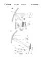
- FIG. 3is a side plane view of a multi-pattern antenna in accordance with a first embodiment of the invention
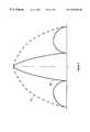
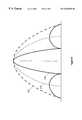
- FIG. 4shows antenna patterns generated by the antenna of FIG. 3
- FIG. 5is a side plane view of a multi-pattern antenna in accordance with the preferred embodiment of the invention.
- FIG. 6shows antenna patterns generated by the antenna of FIG. 5;
- FIG. 7is a side plane view of a multi-pattern antenna in accordance with a second embodiment of the invention.
- the antenna 37can be configured as a receive only antenna, a transmit only antenna, or a combination transmit receive antenna.
- the transmit only casewill be described but as is known to one skilled in the art, the same concepts apply for the other configurations.
- the embodiments of the inventionwill be detailed as if the antenna 90 were configured in a transmit-only mode, however, it will be obvious to one skilled in the art that the concepts apply to the receive mode as well.
- the 20 and 30 GHz waveguides 116 , 119are coupled to an electronics package 122 .
- the electronics packagegenerates the 20 & 30 GHz RF signals and provides those signals to the 20 & 30 GHz waveguides 116 , 119 respectively.
- the waveguides 116 , 119supply the 20 & 30 GHz RF signals to the first 114 and second 118 feed horns respectively.
- the reflector 102 , the subreflectors 96 , 98 and the feeds 114 , 118are configured so that the antenna patterns 92 , 94 are generated by the reflector 102 free of obstruction by the feeds 114 , 118 and subreflectors 96 , 98 .
Landscapes
- Physics & Mathematics (AREA)
- Electromagnetism (AREA)
- Aerials With Secondary Devices (AREA)
- Variable-Direction Aerials And Aerial Arrays (AREA)
Abstract
Description
Claims (19)
Priority Applications (4)
| Application Number | Priority Date | Filing Date | Title |
|---|---|---|---|
| US09/394,386US6545645B1 (en) | 1999-09-10 | 1999-09-10 | Compact frequency selective reflective antenna |
| CA002316658ACA2316658C (en) | 1999-09-10 | 2000-08-24 | Compact frequency selective reflector antenna |
| EP00119345AEP1083626A3 (en) | 1999-09-10 | 2000-09-07 | Compact frequency selective reflector antenna |
| JP2000273052AJP2001111333A (en) | 1999-09-10 | 2000-09-08 | Compact frequency selective reflection antenna |
Applications Claiming Priority (1)
| Application Number | Priority Date | Filing Date | Title |
|---|---|---|---|
| US09/394,386US6545645B1 (en) | 1999-09-10 | 1999-09-10 | Compact frequency selective reflective antenna |
Publications (1)
| Publication Number | Publication Date |
|---|---|
| US6545645B1true US6545645B1 (en) | 2003-04-08 |
Family
ID=23558752
Family Applications (1)
| Application Number | Title | Priority Date | Filing Date |
|---|---|---|---|
| US09/394,386Expired - LifetimeUS6545645B1 (en) | 1999-09-10 | 1999-09-10 | Compact frequency selective reflective antenna |
Country Status (4)
| Country | Link |
|---|---|
| US (1) | US6545645B1 (en) |
| EP (1) | EP1083626A3 (en) |
| JP (1) | JP2001111333A (en) |
| CA (1) | CA2316658C (en) |
Cited By (29)
| Publication number | Priority date | Publication date | Assignee | Title |
|---|---|---|---|---|
| US6774861B2 (en)* | 2002-06-19 | 2004-08-10 | Northrop Grumman Corporation | Dual band hybrid offset reflector antenna system |
| US6795034B2 (en)* | 2002-07-10 | 2004-09-21 | The Boeing Company | Gregorian antenna system for shaped beam and multiple frequency use |
| US20050099351A1 (en)* | 2003-11-07 | 2005-05-12 | Gothard Griffin K. | Multi-band coaxial ring-focus antenna with co-located subreflectors |
| US20050110694A1 (en)* | 2001-09-14 | 2005-05-26 | Andrew Corporation | Co-Located Multi-Band Antenna |
| US20080094298A1 (en)* | 2006-10-23 | 2008-04-24 | Harris Corporation | Antenna with Shaped Asymmetric Main Reflector and Subreflector with Asymmetric Waveguide Feed |
| US20110215190A1 (en)* | 2009-06-19 | 2011-09-08 | Mbda Uk Limited | Antennas |
| US20150255877A1 (en)* | 2012-11-20 | 2015-09-10 | Kuang-Chi Innovative Technology Ltd. | Metamaterial, metamaterial preparation method and metamaterial design method |
| US20150276928A1 (en)* | 2014-03-26 | 2015-10-01 | Elwha Llc | Methods and apparatus for controlling a surface scattering antenna array |
| US9647345B2 (en) | 2013-10-21 | 2017-05-09 | Elwha Llc | Antenna system facilitating reduction of interfering signals |
| US9711852B2 (en) | 2014-06-20 | 2017-07-18 | The Invention Science Fund I Llc | Modulation patterns for surface scattering antennas |
| US20170264020A1 (en)* | 2015-06-19 | 2017-09-14 | Hughes Network Systems, Llc | Satellite ground terminal utilizing frequency-selective surface subreflector |
| US9825358B2 (en) | 2013-12-17 | 2017-11-21 | Elwha Llc | System wirelessly transferring power to a target device over a modeled transmission pathway without exceeding a radiation limit for human beings |
| US9853361B2 (en) | 2014-05-02 | 2017-12-26 | The Invention Science Fund I Llc | Surface scattering antennas with lumped elements |
| US9882288B2 (en) | 2014-05-02 | 2018-01-30 | The Invention Science Fund I Llc | Slotted surface scattering antennas |
| US9923271B2 (en) | 2013-10-21 | 2018-03-20 | Elwha Llc | Antenna system having at least two apertures facilitating reduction of interfering signals |
| US9929474B2 (en) | 2015-07-02 | 2018-03-27 | Sea Tel, Inc. | Multiple-feed antenna system having multi-position subreflector assembly |
| US9935375B2 (en) | 2013-12-10 | 2018-04-03 | Elwha Llc | Surface scattering reflector antenna |
| US10062968B2 (en) | 2010-10-15 | 2018-08-28 | The Invention Science Fund I Llc | Surface scattering antennas |
| US10074888B2 (en) | 2015-04-03 | 2018-09-11 | NXT-ID, Inc. | Accordion antenna structure |
| US10090599B2 (en) | 2013-03-15 | 2018-10-02 | The Invention Science Fund I Llc | Surface scattering antenna improvements |
| US10178560B2 (en) | 2015-06-15 | 2019-01-08 | The Invention Science Fund I Llc | Methods and systems for communication with beamforming antennas |
| US10361481B2 (en) | 2016-10-31 | 2019-07-23 | The Invention Science Fund I, Llc | Surface scattering antennas with frequency shifting for mutual coupling mitigation |
| US10446903B2 (en) | 2014-05-02 | 2019-10-15 | The Invention Science Fund I, Llc | Curved surface scattering antennas |
| US20200052411A1 (en)* | 2016-04-12 | 2020-02-13 | Intellian Technologies Inc. | Antenna for satellite communication capable of receiving multi-band signal |
| US10637151B2 (en)* | 2017-04-26 | 2020-04-28 | Electronics And Telecommunications Research Institute | Transceiver in wireless communication system |
| US10887004B2 (en)* | 2017-06-09 | 2021-01-05 | Airbus Defence And Space Sas | Telecommunications satellite, beamforming method and method for manufacturing a satellite payload |
| US10931364B2 (en)* | 2017-11-08 | 2021-02-23 | Airbus Defence And Space Sas | Satellite payload comprising a dual reflective surface reflector |
| US11133598B2 (en)* | 2017-07-25 | 2021-09-28 | Sea Tel, Inc. | Antenna system with multiple synchronously movable feeds |
| US20220021111A1 (en)* | 2018-11-08 | 2022-01-20 | Orbit Communication Systems Ltd. | Low Profile Multi Band Antenna System |
Families Citing this family (9)
| Publication number | Priority date | Publication date | Assignee | Title |
|---|---|---|---|---|
| US6606077B2 (en)* | 1999-11-18 | 2003-08-12 | Automotive Systems Laboratory, Inc. | Multi-beam antenna |
| GB2442796A (en)* | 2006-10-11 | 2008-04-16 | John Thornton | Hemispherical lens with a selective reflective planar surface for a multi-beam antenna |
| JP5371633B2 (en)* | 2008-09-30 | 2013-12-18 | 株式会社エヌ・ティ・ティ・ドコモ | Reflect array |
| JP5297349B2 (en)* | 2009-11-13 | 2013-09-25 | 株式会社エヌ・ティ・ティ・ドコモ | Reflect array |
| WO2014114953A2 (en)* | 2013-01-28 | 2014-07-31 | Bae Systems Plc | Directional multi-band antenna |
| EP2760081A1 (en)* | 2013-01-28 | 2014-07-30 | BAE Systems PLC | Directional multi-band antenna |
| US10559888B2 (en) | 2015-06-19 | 2020-02-11 | Hughes Network Systems, Llc | Satellite ground terminal utilizing frequency-selective surface diplexer |
| BR112019025429A2 (en)* | 2017-05-31 | 2020-06-16 | Hughes Network Systems | COMMUNICATION TERMINAL FOR SATELLITE COMMUNICATIONS AND METHODS |
| KR102420112B1 (en) | 2022-05-06 | 2022-07-11 | 국방과학연구소 | Apparatus and method of crpa neutralization for illegal unmanned aerial vehicle |
Citations (6)
| Publication number | Priority date | Publication date | Assignee | Title |
|---|---|---|---|---|
| JPS54114065A (en) | 1978-02-24 | 1979-09-05 | Nippon Telegr & Teleph Corp <Ntt> | Beam variable antenna |
| US4342036A (en)* | 1980-12-29 | 1982-07-27 | Ford Aerospace & Communications Corporation | Multiple frequency band, multiple beam microwave antenna system |
| US4701765A (en)* | 1984-11-08 | 1987-10-20 | Cselt-Centro Studi E Laboratori Telecomunicazioni S.P.A. | Structure for a dichroic antenna |
| US5130718A (en) | 1990-10-23 | 1992-07-14 | Hughes Aircraft Company | Multiple dichroic surface cassegrain reflector |
| US5373302A (en)* | 1992-06-24 | 1994-12-13 | The United States Of America As Represented By The Administrator Of The National Aeronautics And Space Administration | Double-loop frequency selective surfaces for multi frequency division multiplexing in a dual reflector antenna |
| US5576721A (en)* | 1993-03-31 | 1996-11-19 | Space Systems/Loral, Inc. | Composite multi-beam and shaped beam antenna system |
- 1999
- 1999-09-10USUS09/394,386patent/US6545645B1/ennot_activeExpired - Lifetime
- 2000
- 2000-08-24CACA002316658Apatent/CA2316658C/ennot_activeExpired - Fee Related
- 2000-09-07EPEP00119345Apatent/EP1083626A3/ennot_activeWithdrawn
- 2000-09-08JPJP2000273052Apatent/JP2001111333A/enactivePending
Patent Citations (6)
| Publication number | Priority date | Publication date | Assignee | Title |
|---|---|---|---|---|
| JPS54114065A (en) | 1978-02-24 | 1979-09-05 | Nippon Telegr & Teleph Corp <Ntt> | Beam variable antenna |
| US4342036A (en)* | 1980-12-29 | 1982-07-27 | Ford Aerospace & Communications Corporation | Multiple frequency band, multiple beam microwave antenna system |
| US4701765A (en)* | 1984-11-08 | 1987-10-20 | Cselt-Centro Studi E Laboratori Telecomunicazioni S.P.A. | Structure for a dichroic antenna |
| US5130718A (en) | 1990-10-23 | 1992-07-14 | Hughes Aircraft Company | Multiple dichroic surface cassegrain reflector |
| US5373302A (en)* | 1992-06-24 | 1994-12-13 | The United States Of America As Represented By The Administrator Of The National Aeronautics And Space Administration | Double-loop frequency selective surfaces for multi frequency division multiplexing in a dual reflector antenna |
| US5576721A (en)* | 1993-03-31 | 1996-11-19 | Space Systems/Loral, Inc. | Composite multi-beam and shaped beam antenna system |
Non-Patent Citations (3)
| Title |
|---|
| Honma, S., et al., "Performance Measurement of Frequency Selective Reflector Using Planar Near-Field Techniques," Jun. 18, 1995, IEEE Antennas and Propagation Society International Symposium Digest, vol. 3, pp. 1663-1666. |
| Pelton, Edward L., et al., "Scattering from Periodic Arrays of Crossed Dipoles," May 1979, IEEE Transactions on Antennas and Propagation, vol. AP-27, No. 3, pp. 323-330. |
| Ueno, K., et al, "Low-Loss Ka-Band Frequency Selective Subreflector," Jun. 20, 1991, Electronic Letters, IEE Stevenage, GB, vol. 27, No. 13, p. 1155. |
Cited By (48)
| Publication number | Priority date | Publication date | Assignee | Title |
|---|---|---|---|---|
| US20050110694A1 (en)* | 2001-09-14 | 2005-05-26 | Andrew Corporation | Co-Located Multi-Band Antenna |
| US7038632B2 (en)* | 2001-09-14 | 2006-05-02 | Andrew Corporation | Co-located multi-band antenna |
| US6774861B2 (en)* | 2002-06-19 | 2004-08-10 | Northrop Grumman Corporation | Dual band hybrid offset reflector antenna system |
| US6795034B2 (en)* | 2002-07-10 | 2004-09-21 | The Boeing Company | Gregorian antenna system for shaped beam and multiple frequency use |
| US20050099351A1 (en)* | 2003-11-07 | 2005-05-12 | Gothard Griffin K. | Multi-band coaxial ring-focus antenna with co-located subreflectors |
| US6937201B2 (en) | 2003-11-07 | 2005-08-30 | Harris Corporation | Multi-band coaxial ring-focus antenna with co-located subreflectors |
| US20080094298A1 (en)* | 2006-10-23 | 2008-04-24 | Harris Corporation | Antenna with Shaped Asymmetric Main Reflector and Subreflector with Asymmetric Waveguide Feed |
| US20110215190A1 (en)* | 2009-06-19 | 2011-09-08 | Mbda Uk Limited | Antennas |
| US8680450B2 (en)* | 2009-06-19 | 2014-03-25 | Mbda Uk Limited | Antennas |
| US10320084B2 (en) | 2010-10-15 | 2019-06-11 | The Invention Science Fund I Llc | Surface scattering antennas |
| US10062968B2 (en) | 2010-10-15 | 2018-08-28 | The Invention Science Fund I Llc | Surface scattering antennas |
| US20150255877A1 (en)* | 2012-11-20 | 2015-09-10 | Kuang-Chi Innovative Technology Ltd. | Metamaterial, metamaterial preparation method and metamaterial design method |
| US9653815B2 (en)* | 2012-11-20 | 2017-05-16 | Kuang-Chi Innovative Technology Ltd. | Metamaterial, metamaterial preparation method and metamaterial design method |
| US10090599B2 (en) | 2013-03-15 | 2018-10-02 | The Invention Science Fund I Llc | Surface scattering antenna improvements |
| US10673145B2 (en) | 2013-10-21 | 2020-06-02 | Elwha Llc | Antenna system facilitating reduction of interfering signals |
| US9923271B2 (en) | 2013-10-21 | 2018-03-20 | Elwha Llc | Antenna system having at least two apertures facilitating reduction of interfering signals |
| US9647345B2 (en) | 2013-10-21 | 2017-05-09 | Elwha Llc | Antenna system facilitating reduction of interfering signals |
| US9935375B2 (en) | 2013-12-10 | 2018-04-03 | Elwha Llc | Surface scattering reflector antenna |
| US10236574B2 (en) | 2013-12-17 | 2019-03-19 | Elwha Llc | Holographic aperture antenna configured to define selectable, arbitrary complex electromagnetic fields |
| US9871291B2 (en) | 2013-12-17 | 2018-01-16 | Elwha Llc | System wirelessly transferring power to a target device over a tested transmission pathway |
| US9825358B2 (en) | 2013-12-17 | 2017-11-21 | Elwha Llc | System wirelessly transferring power to a target device over a modeled transmission pathway without exceeding a radiation limit for human beings |
| US9843103B2 (en)* | 2014-03-26 | 2017-12-12 | Elwha Llc | Methods and apparatus for controlling a surface scattering antenna array |
| US20150276928A1 (en)* | 2014-03-26 | 2015-10-01 | Elwha Llc | Methods and apparatus for controlling a surface scattering antenna array |
| US9882288B2 (en) | 2014-05-02 | 2018-01-30 | The Invention Science Fund I Llc | Slotted surface scattering antennas |
| US9853361B2 (en) | 2014-05-02 | 2017-12-26 | The Invention Science Fund I Llc | Surface scattering antennas with lumped elements |
| US10727609B2 (en) | 2014-05-02 | 2020-07-28 | The Invention Science Fund I, Llc | Surface scattering antennas with lumped elements |
| US10446903B2 (en) | 2014-05-02 | 2019-10-15 | The Invention Science Fund I, Llc | Curved surface scattering antennas |
| US9711852B2 (en) | 2014-06-20 | 2017-07-18 | The Invention Science Fund I Llc | Modulation patterns for surface scattering antennas |
| US10074888B2 (en) | 2015-04-03 | 2018-09-11 | NXT-ID, Inc. | Accordion antenna structure |
| US10461396B2 (en) | 2015-04-03 | 2019-10-29 | Fit Pay, Inc. | System and method for low-power close-proximity communications and energy transfer using a miniature multi-purpose antenna |
| US10178560B2 (en) | 2015-06-15 | 2019-01-08 | The Invention Science Fund I Llc | Methods and systems for communication with beamforming antennas |
| US10658757B2 (en)* | 2015-06-19 | 2020-05-19 | Hughes Network Systems, Llc | Satellite ground terminal utilizing frequency-selective surface subreflector |
| US20170264020A1 (en)* | 2015-06-19 | 2017-09-14 | Hughes Network Systems, Llc | Satellite ground terminal utilizing frequency-selective surface subreflector |
| US9929474B2 (en) | 2015-07-02 | 2018-03-27 | Sea Tel, Inc. | Multiple-feed antenna system having multi-position subreflector assembly |
| US11699859B2 (en) | 2015-07-02 | 2023-07-11 | Sea Tel, Inc. | Multiple-feed antenna system having multi-position subreflector assembly |
| US10498043B2 (en) | 2015-07-02 | 2019-12-03 | Sea Tel, Inc. | Multiple-feed antenna system having multi-position subreflector assembly |
| US10170842B2 (en) | 2015-07-02 | 2019-01-01 | Sea Tel, Inc. | Multiple-feed antenna system having multi-position subreflector assembly |
| US12126082B2 (en) | 2015-07-02 | 2024-10-22 | Sea Tel, Inc. | Multiple-feed antenna system having multi-position subreflector assembly |
| US10998637B2 (en) | 2015-07-02 | 2021-05-04 | Sea Tel, Inc. | Multiple-feed antenna system having multi-position subreflector assembly |
| US10879621B2 (en)* | 2016-04-12 | 2020-12-29 | Intellian Technologies Inc. | Antenna for satellite communication capable of receiving multi-band signal |
| US20200052411A1 (en)* | 2016-04-12 | 2020-02-13 | Intellian Technologies Inc. | Antenna for satellite communication capable of receiving multi-band signal |
| US10361481B2 (en) | 2016-10-31 | 2019-07-23 | The Invention Science Fund I, Llc | Surface scattering antennas with frequency shifting for mutual coupling mitigation |
| US10637151B2 (en)* | 2017-04-26 | 2020-04-28 | Electronics And Telecommunications Research Institute | Transceiver in wireless communication system |
| US10887004B2 (en)* | 2017-06-09 | 2021-01-05 | Airbus Defence And Space Sas | Telecommunications satellite, beamforming method and method for manufacturing a satellite payload |
| US11133598B2 (en)* | 2017-07-25 | 2021-09-28 | Sea Tel, Inc. | Antenna system with multiple synchronously movable feeds |
| US10931364B2 (en)* | 2017-11-08 | 2021-02-23 | Airbus Defence And Space Sas | Satellite payload comprising a dual reflective surface reflector |
| US20220021111A1 (en)* | 2018-11-08 | 2022-01-20 | Orbit Communication Systems Ltd. | Low Profile Multi Band Antenna System |
| US12283750B2 (en)* | 2018-11-08 | 2025-04-22 | Orbit Communication Systems Ltd. | Low profile multi band antenna system |
Also Published As
| Publication number | Publication date |
|---|---|
| CA2316658A1 (en) | 2001-03-10 |
| CA2316658C (en) | 2004-01-06 |
| JP2001111333A (en) | 2001-04-20 |
| EP1083626A2 (en) | 2001-03-14 |
| EP1083626A3 (en) | 2002-06-26 |
Similar Documents
| Publication | Publication Date | Title |
|---|---|---|
| US6545645B1 (en) | Compact frequency selective reflective antenna | |
| US6169524B1 (en) | Multi-pattern antenna having frequency selective or polarization sensitive zones | |
| US4772890A (en) | Multi-band planar antenna array | |
| US6885355B2 (en) | Spatial filtering surface operative with antenna aperture for modifying aperture electric field | |
| Shaker et al. | Reflectarray antennas: analysis, design, fabrication, and measurement | |
| US6900763B2 (en) | Antenna system with spatial filtering surface | |
| US6806843B2 (en) | Antenna system with active spatial filtering surface | |
| EP0689264B1 (en) | Multiple band folding antenna | |
| US6268835B1 (en) | Deployable phased array of reflectors and method of operation | |
| EP1070366B1 (en) | Multiple parasitic coupling from inner patch antenna elements to outer patch antenna elements | |
| US5471224A (en) | Frequency selective surface with repeating pattern of concentric closed conductor paths, and antenna having the surface | |
| US8059051B2 (en) | Planar dielectric waveguide with metal grid for antenna applications | |
| US20050219145A1 (en) | Complementary dual antenna system | |
| US6747608B2 (en) | High performance multi-band frequency selective reflector with equal beam coverage | |
| US2870444A (en) | Radiating systems | |
| US6384795B1 (en) | Multi-step circular horn system | |
| US8791875B2 (en) | Method and apparatus for avoiding pattern blockage due to scatter | |
| JP2021057722A (en) | Radio wave transmission plate and radio wave transmission system | |
| JPH05315826A (en) | Antenna scanned by frequency change | |
| US5977926A (en) | Multi-focus reflector antenna | |
| JP2002171122A (en) | Antenna device | |
| CA2058304A1 (en) | Antenna apparatus with reflector or lens consisting of a frequency scanned grating | |
| JP7514736B2 (en) | Antenna Device | |
| JPH01502230A (en) | Composite antenna reflector with polarization sub-reflector | |
| TW486842B (en) | Planar leaky-wave retrodirective antenna arrays |
Legal Events
| Date | Code | Title | Description |
|---|---|---|---|
| AS | Assignment | Owner name:TRW INC., CALIFORNIA Free format text:ASSIGNMENT OF ASSIGNORS INTEREST;ASSIGNOR:WU, TE-KAO;REEL/FRAME:010248/0164 Effective date:19990909 | |
| AS | Assignment | Owner name:NORTHROP GRUMMAN CORPORATION, CALIFORNIA Free format text:ASSIGNMENT OF ASSIGNORS INTEREST;ASSIGNOR:TRW, INC. N/K/A NORTHROP GRUMMAN SPACE AND MISSION SYSTEMS CORPORATION, AN OHIO CORPORATION;REEL/FRAME:013751/0849 Effective date:20030122 Owner name:NORTHROP GRUMMAN CORPORATION,CALIFORNIA Free format text:ASSIGNMENT OF ASSIGNORS INTEREST;ASSIGNOR:TRW, INC. N/K/A NORTHROP GRUMMAN SPACE AND MISSION SYSTEMS CORPORATION, AN OHIO CORPORATION;REEL/FRAME:013751/0849 Effective date:20030122 | |
| STCF | Information on status: patent grant | Free format text:PATENTED CASE | |
| FPAY | Fee payment | Year of fee payment:4 | |
| FEPP | Fee payment procedure | Free format text:PAYOR NUMBER ASSIGNED (ORIGINAL EVENT CODE: ASPN); ENTITY STATUS OF PATENT OWNER: LARGE ENTITY | |
| AS | Assignment | Owner name:NORTHROP GRUMMAN SPACE & MISSION SYSTEMS CORP.,CAL Free format text:ASSIGNMENT OF ASSIGNORS INTEREST;ASSIGNOR:NORTHROP GRUMMAN CORPORTION;REEL/FRAME:023699/0551 Effective date:20091125 Owner name:NORTHROP GRUMMAN SPACE & MISSION SYSTEMS CORP., CA Free format text:ASSIGNMENT OF ASSIGNORS INTEREST;ASSIGNOR:NORTHROP GRUMMAN CORPORTION;REEL/FRAME:023699/0551 Effective date:20091125 | |
| AS | Assignment | Owner name:NORTHROP GRUMMAN SYSTEMS CORPORATION,CALIFORNIA Free format text:ASSIGNMENT OF ASSIGNORS INTEREST;ASSIGNOR:NORTHROP GRUMMAN SPACE & MISSION SYSTEMS CORP.;REEL/FRAME:023915/0446 Effective date:20091210 Owner name:NORTHROP GRUMMAN SYSTEMS CORPORATION, CALIFORNIA Free format text:ASSIGNMENT OF ASSIGNORS INTEREST;ASSIGNOR:NORTHROP GRUMMAN SPACE & MISSION SYSTEMS CORP.;REEL/FRAME:023915/0446 Effective date:20091210 | |
| FPAY | Fee payment | Year of fee payment:8 | |
| FPAY | Fee payment | Year of fee payment:12 |