US6544273B1 - Tack device with shield - Google Patents
Tack device with shieldDownload PDFInfo
- Publication number
- US6544273B1 US6544273B1US09/684,108US68410800AUS6544273B1US 6544273 B1US6544273 B1US 6544273B1US 68410800 AUS68410800 AUS 68410800AUS 6544273 B1US6544273 B1US 6544273B1
- Authority
- US
- United States
- Prior art keywords
- tack
- sling
- shield
- head
- alternatively
- Prior art date
- Legal status (The legal status is an assumption and is not a legal conclusion. Google has not performed a legal analysis and makes no representation as to the accuracy of the status listed.)
- Expired - Lifetime, expires
Links
- 210000000988bone and boneAnatomy0.000claimsdescription79
- 238000000034methodMethods0.000description40
- 210000001215vaginaAnatomy0.000description24
- 210000003689pubic boneAnatomy0.000description20
- 210000003708urethraAnatomy0.000description20
- 238000003780insertionMethods0.000description18
- 230000037431insertionEffects0.000description18
- 230000007246mechanismEffects0.000description18
- 210000001519tissueAnatomy0.000description14
- 239000000463materialSubstances0.000description6
- 239000000758substrateSubstances0.000description6
- 206010021639IncontinenceDiseases0.000description4
- 239000000725suspensionSubstances0.000description4
- 230000003187abdominal effectEffects0.000description3
- 239000004033plasticSubstances0.000description3
- 210000004872soft tissueAnatomy0.000description3
- 230000005641tunnelingEffects0.000description3
- 206010046543Urinary incontinenceDiseases0.000description2
- 239000000853adhesiveSubstances0.000description2
- 230000001070adhesive effectEffects0.000description2
- 230000008901benefitEffects0.000description2
- 239000000560biocompatible materialSubstances0.000description2
- 238000002788crimpingMethods0.000description2
- 238000005520cutting processMethods0.000description2
- 239000013013elastic materialSubstances0.000description2
- 210000000056organAnatomy0.000description2
- 230000008569processEffects0.000description2
- 239000012781shape memory materialSubstances0.000description2
- 238000011282treatmentMethods0.000description2
- 229920004934Dacron®Polymers0.000description1
- 230000003213activating effectEffects0.000description1
- 210000003484anatomyAnatomy0.000description1
- 230000008859changeEffects0.000description1
- 238000000576coating methodMethods0.000description1
- 230000006835compressionEffects0.000description1
- 238000007906compressionMethods0.000description1
- 238000010276constructionMethods0.000description1
- 230000008878couplingEffects0.000description1
- 238000010168coupling processMethods0.000description1
- 238000005859coupling reactionMethods0.000description1
- 230000007547defectEffects0.000description1
- 230000002708enhancing effectEffects0.000description1
- 210000003195fasciaAnatomy0.000description1
- 230000006870functionEffects0.000description1
- 239000007943implantSubstances0.000description1
- 238000004519manufacturing processMethods0.000description1
- 230000003278mimic effectEffects0.000description1
- 238000000465mouldingMethods0.000description1
- 230000035515penetrationEffects0.000description1
- 239000005020polyethylene terephthalateSubstances0.000description1
- 238000004080punchingMethods0.000description1
- 230000008439repair processEffects0.000description1
- 230000000979retarding effectEffects0.000description1
- 230000035807sensationEffects0.000description1
- 230000001568sexual effectEffects0.000description1
- 239000007787solidSubstances0.000description1
- 230000001954sterilising effectEffects0.000description1
- 238000004659sterilization and disinfectionMethods0.000description1
- 229920002994synthetic fiberPolymers0.000description1
- 230000008467tissue growthEffects0.000description1
- 210000001835visceraAnatomy0.000description1
Images


Classifications
- A—HUMAN NECESSITIES
- A61—MEDICAL OR VETERINARY SCIENCE; HYGIENE
- A61B—DIAGNOSIS; SURGERY; IDENTIFICATION
- A61B17/00—Surgical instruments, devices or methods
- A61B17/04—Surgical instruments, devices or methods for suturing wounds; Holders or packages for needles or suture materials
- A61B17/0401—Suture anchors, buttons or pledgets, i.e. means for attaching sutures to bone, cartilage or soft tissue; Instruments for applying or removing suture anchors
- A—HUMAN NECESSITIES
- A61—MEDICAL OR VETERINARY SCIENCE; HYGIENE
- A61F—FILTERS IMPLANTABLE INTO BLOOD VESSELS; PROSTHESES; DEVICES PROVIDING PATENCY TO, OR PREVENTING COLLAPSING OF, TUBULAR STRUCTURES OF THE BODY, e.g. STENTS; ORTHOPAEDIC, NURSING OR CONTRACEPTIVE DEVICES; FOMENTATION; TREATMENT OR PROTECTION OF EYES OR EARS; BANDAGES, DRESSINGS OR ABSORBENT PADS; FIRST-AID KITS
- A61F2/00—Filters implantable into blood vessels; Prostheses, i.e. artificial substitutes or replacements for parts of the body; Appliances for connecting them with the body; Devices providing patency to, or preventing collapsing of, tubular structures of the body, e.g. stents
- A61F2/0004—Closure means for urethra or rectum, i.e. anti-incontinence devices or support slings against pelvic prolapse
- A61F2/0031—Closure means for urethra or rectum, i.e. anti-incontinence devices or support slings against pelvic prolapse for constricting the lumen; Support slings for the urethra
- A61F2/0036—Closure means for urethra or rectum, i.e. anti-incontinence devices or support slings against pelvic prolapse for constricting the lumen; Support slings for the urethra implantable
- A61F2/0045—Support slings
- A—HUMAN NECESSITIES
- A61—MEDICAL OR VETERINARY SCIENCE; HYGIENE
- A61B—DIAGNOSIS; SURGERY; IDENTIFICATION
- A61B17/00—Surgical instruments, devices or methods
- A61B17/064—Surgical staples, i.e. penetrating the tissue
- A61B17/0642—Surgical staples, i.e. penetrating the tissue for bones, e.g. for osteosynthesis or connecting tendon to bone
- A—HUMAN NECESSITIES
- A61—MEDICAL OR VETERINARY SCIENCE; HYGIENE
- A61B—DIAGNOSIS; SURGERY; IDENTIFICATION
- A61B17/00—Surgical instruments, devices or methods
- A61B2017/00743—Type of operation; Specification of treatment sites
- A61B2017/00805—Treatment of female stress urinary incontinence
- A—HUMAN NECESSITIES
- A61—MEDICAL OR VETERINARY SCIENCE; HYGIENE
- A61B—DIAGNOSIS; SURGERY; IDENTIFICATION
- A61B17/00—Surgical instruments, devices or methods
- A61B2017/00831—Material properties
- A61B2017/00867—Material properties shape memory effect
- A—HUMAN NECESSITIES
- A61—MEDICAL OR VETERINARY SCIENCE; HYGIENE
- A61B—DIAGNOSIS; SURGERY; IDENTIFICATION
- A61B17/00—Surgical instruments, devices or methods
- A61B17/04—Surgical instruments, devices or methods for suturing wounds; Holders or packages for needles or suture materials
- A61B17/0401—Suture anchors, buttons or pledgets, i.e. means for attaching sutures to bone, cartilage or soft tissue; Instruments for applying or removing suture anchors
- A61B2017/0409—Instruments for applying suture anchors
- A—HUMAN NECESSITIES
- A61—MEDICAL OR VETERINARY SCIENCE; HYGIENE
- A61B—DIAGNOSIS; SURGERY; IDENTIFICATION
- A61B17/00—Surgical instruments, devices or methods
- A61B17/04—Surgical instruments, devices or methods for suturing wounds; Holders or packages for needles or suture materials
- A61B17/0401—Suture anchors, buttons or pledgets, i.e. means for attaching sutures to bone, cartilage or soft tissue; Instruments for applying or removing suture anchors
- A61B2017/0412—Suture anchors, buttons or pledgets, i.e. means for attaching sutures to bone, cartilage or soft tissue; Instruments for applying or removing suture anchors having anchoring barbs or pins extending outwardly from suture anchor body
- A—HUMAN NECESSITIES
- A61—MEDICAL OR VETERINARY SCIENCE; HYGIENE
- A61B—DIAGNOSIS; SURGERY; IDENTIFICATION
- A61B17/00—Surgical instruments, devices or methods
- A61B17/04—Surgical instruments, devices or methods for suturing wounds; Holders or packages for needles or suture materials
- A61B17/0401—Suture anchors, buttons or pledgets, i.e. means for attaching sutures to bone, cartilage or soft tissue; Instruments for applying or removing suture anchors
- A61B2017/0427—Suture anchors, buttons or pledgets, i.e. means for attaching sutures to bone, cartilage or soft tissue; Instruments for applying or removing suture anchors having anchoring barbs or pins extending outwardly from the anchor body
- A61B2017/0437—Suture anchors, buttons or pledgets, i.e. means for attaching sutures to bone, cartilage or soft tissue; Instruments for applying or removing suture anchors having anchoring barbs or pins extending outwardly from the anchor body the barbs being resilient or spring-like
- A—HUMAN NECESSITIES
- A61—MEDICAL OR VETERINARY SCIENCE; HYGIENE
- A61B—DIAGNOSIS; SURGERY; IDENTIFICATION
- A61B17/00—Surgical instruments, devices or methods
- A61B17/04—Surgical instruments, devices or methods for suturing wounds; Holders or packages for needles or suture materials
- A61B17/0401—Suture anchors, buttons or pledgets, i.e. means for attaching sutures to bone, cartilage or soft tissue; Instruments for applying or removing suture anchors
- A61B2017/044—Suture anchors, buttons or pledgets, i.e. means for attaching sutures to bone, cartilage or soft tissue; Instruments for applying or removing suture anchors with a threaded shaft, e.g. screws
- A—HUMAN NECESSITIES
- A61—MEDICAL OR VETERINARY SCIENCE; HYGIENE
- A61B—DIAGNOSIS; SURGERY; IDENTIFICATION
- A61B17/00—Surgical instruments, devices or methods
- A61B17/064—Surgical staples, i.e. penetrating the tissue
- A61B2017/0647—Surgical staples, i.e. penetrating the tissue having one single leg, e.g. tacks
Definitions
- the present inventionrelates to methods and apparatus for treating incontinence, especially by bladder neck support.
- Urinary incontinenceis an unfortunately common medical complaint. Many treatments have been suggested. Recently, a relatively minimally invasive technique has become more common, in which a bladder neck and/or urethra is supported by a sling, so that the urethra is partially compressed and/or has a support below it so that during straining and/or bladder/uretheral descent, pressure is applied between the urethra and the sling, thereby closing its lumen.
- Benderev et. alin U.S. Pat. No. 5,836,314 and Brenneman et al, in PCT publication WO 98/19606, the disclosures of which are incorporated herein by reference, describe exemplary procedures for treating incontinence.
- Two or more bone anchorsare attached to the pubic bone. Each anchor is pre-threaded with a suture.
- Brennemansuggests attaching a sling to the sutures such that when the sutures are pulled tight and knotted, the sling is urged towards the pubic bone.
- Benderevsuggests integrally molding one end of a suture with a “suture support,” which suture support is provided to prevent damage to the urethra by the sutures.
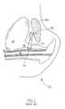
- FIG. 1is a schematic side cut-through illustration of a pubic region 20 during such a procedure, before the sutures are tightened.
- a sling 32is located between a vagina 22 and a bladder neck 26 of a bladder 24 .
- the slingis threaded by a plurality of sutures 36 , which are attached to a bone anchor 30 , in a pubic bone 28 .
- sling 32there are two commonly applied methods of bringing sling 32 to a position between vagina 22 and bladder neck 26 .
- a first methodan incision is made in the vagina, at an area corresponding to that marked with reference number 34 , perpendicular to the figure plane, thereby forming a flap.
- the slingis inserted into the incision, under the flap, and after the sling is tightened, the incision is closed.
- a second methodonly a small hole in the vagina lining is made for each inserted bone anchor and a tunnel is formed between the two holes, for insertion of sling 32 therethrough.
- the sutureis an additional element which may be damaged during the procedure or after it;
- the suturesmay damage the sling by cutting through it (older tissue being more susceptible); if the suture enters the sling at multiple points (to reduce strain at the sling-suture joints) the sling may be deformed by the sutures.
- An aspect of some preferred embodiments of the present inventionrelates to a sutureless method of supporting a bladder neck.
- the bladder neckis supported by a sling, and the sling is directly tacked to a pubic bone, without intermediate sutures.
- the slingis directly attached to the bone using other means, for example an adhesive.
- directly attachedmeans attached without an intermediate suture.
- the slingwill not be in direct physical contact with the bone. Generally, but not necessarily, there will be only tissue (if any) between the sling and the bone. However, in a preferred embodiment of the invention, there will not be a suture or other implant between the sling and the bone.
- An aspect of some embodiments of the inventionrelates to a tack shield.
- the tackwhen a tack is mounted on a tack head, for use in the body, the tack is surrounded by a shield, so that the tack tip and/or other parts of the tack, do not inadvertently damage the body.
- the shieldis retractable.
- the shieldis flexible or bendable, being pushed back by forceful contact of the shield with a bone, to reveal the tack.
- the shieldincludes at least one slot adapted for receiving a sling from the side of the shield.
- the slingcan lie flat while it is mounted on the tack and the shield is protecting the body from the tack.
- the shieldis rotationally fixed relative to the tack head, so that the sling placement can be known outside the body.
- the entire shieldneed not be flexible, for example, only the part defining the slot(s) may be flexible. However, it may be simpler to manufacture the shield from a single material.
- an aspect of some embodiments of the inventionrelates to a device for assisting in mounting a sling on a tack.
- the devicecomprises a peg portion with an aperture formed at a tip thereof, for reversibly receiving the tip of a tack.
- a slingis placed between the aperture and the tack tip, and the peg is advanced towards the tack, forcing the tack tip to penetrate the sling.
- the pegincludes a finger guard, to protect fingers holding the peg from the tip of the tack, if the peg slips.
- a peg-like tipmay be mounted on a handle, for example a perpendicular bar.
- a portion of the peg, near the apertureis slightly tacky, to engage the sling prior to mounting.
- the peg near the apertureis slotted, to hold the sling.
- the peg diameteris larger than the sling width.
- the sling mounting deviceis used in conjunction with a slotted shield.
- the sling mounting devicecan apply enough force to bend back the shield.
- the peg portionis mounted on one jaw of a pliers, with the other jaw adapted to engage the tack head behind the tack, for example, so that a greater contact force can be applied and/or so that the tack head does not inadvertently move.
- the pegis a one-time device.
- the pegmust be broken in order to remove it from the tip.
- the pegincludes a draw string down its side for splitting the peg.
- An aspect of some preferred embodiments of the inventionrelates to a sling that is preloaded with one or more tacks at one or both ends thereof prior to insertion into a body.
- the pre-loaded slingis mounted on a tacker, for insertion into the body.
- the slingis not provided as pre-mounted on a tack and is mounted on a tack only after the tack is mounted on a tacker with a protruding tack.
- the mounting of the slingis a two step process, in which the tack is assembled after the sling is mounted on it.
- a tackcomprises a shaft and a head, where the head has a maximum extent perpendicular to the shaft, which extent (the width of the head) is considerably greater the shaft diameter.
- the width of the headis made considerably greater than a maximum extent of a bone-entering portion of the tack (which is usually wider than the shaft).
- the headis larger than the hole formed in the sling by its being tacked and the head can maintain the sling in place.
- the headis substantially circular or polygonal.
- the headis a bar-shaped beam which is perpendicular to the shaft.
- the headmay be large, it is not necessarily solid. Rather, one or more holes may be formed in the head. Optionally, these holes are used for threading the sling through them.
- the headcan rotate relative to the shaft.
- An aspect of some preferred embodiments of the inventionrelates to disassembled or deformable tacks, in which a sling may be pierced with a small diameter portion of the tack.
- the tackis then assembled or deformed, so that the head and/or bone entering portions of the tack have a larger diameter than the piercing portion.
- the tackcomprises two parts, a head with a shaft portion and a bone-entering portion. The sling is pierced by the shaft portion and then the bone-entering portion is attached to a protruding end of the tack.
- the bone-entering portionis maintained at a small diameter until after it pierces the sling, for example by a fin in the shaft receding into a recess formed in the shaft or by the shaft being expandable.
- the headis separate from the shaft.
- An aspect of some preferred embodiments of the inventionrelates to an attachment to a bone stapler, which attachment holds a sling in place over a staple-exit portion of the stapler, to enable a standard stapler or a standard bone-anchor inserter to be used for tacking slings in accordance with a preferred embodiment of the invention.
- the type of stapler providedis such that the tip of the staple does not protrude from the stapler, so the sling is preferably maintained in place solely by the attachment.
- the tip of the stapledoes protrude from the stapler and may serve to at least partially hold the sling, while the attachment fixes the orientation of the sling relative to the staple or the attachment. If a two prong staple (or tack) is used, such an attachment may serve solely to keep the sling from slipping off the tip of the staple.
- An aspect, of some preferred embodiments of the inventionrelates to a tacker which includes two stapling heads, for simultaneous tacking of two sides of a sling.
- the tackercomprises two arms, with a tacking head at the end of each arm.
- the angle between the armsis controllable to adapt the tacker for different length slings.
- the slingis pre-mounted on the two heads prior to insertion into the body.
- a surgical tackcomprising:
- a single shaftformed of a blo-compatible material and having a tip adapted for entering and engaging bone
- said shaftis a separate element from said head.
- said headis rotatable relative to said shaft.
- said headis mounted in a slot defined at an end of said shaft.
- said headis mounted on a narrowing of said shaft.
- said headcomprises only one arm extending substantially perpendicular to said shaft.
- said headcomprises at least two arms extending substantially perpendicular to said shaft.
- said headcomprises at least one arm extending at an angle to said shaft.
- said headdefines a plurality of apertures therethrough.
- said headcomprises a plurality of protrusions extending in a direction of said tip, which protrusions are adapted for engaging said substrate.
- said protrusionsare smooth at a portion thereof where they engage said substrate.
- said protrusionsare pointed at a portion thereof where they engage said substrate.
- said protrusionsextend at least half a thickness of the substrate.
- the tackcomprises at least one fin extending from said shaft, distal from said head, and adapted for engaging said bone after insertion of said shaft into said bone.
- said at least one fincomprises at least two angularly spaced apart fins.
- said at least one fincomprises at least two axially spaced apart fins.
- said at least one fincomprises a separate element from said shaft.
- said at least one finis integrally formed with said shaft.
- said shaftdefines a recess and said at least one fin is adapted for recessing into said defined recess, when force having a vector perpendicular to said shaft is applied to said fin.
- said at least one finis mounted on a separate fin element, which is attached to said shaft.
- said headis roughened at a portion thereof that engages said substrate.
- said tackcomprises an advance-stop on said shaft adjacent said head and separate from said head, such that said advance-stop prevents said head, at portions near said shaft, from touching said bone.
- said headhas two configurations, one in which it has an substantially large transaxial extent and one in which it has a substantially small transaxial extent.
- a tack insertion devicecomprising:
- slotted tack holderat a second end of said body, wherein said slotted tack holder holds a tack pointed towards said handle and wherein said slot is adapted for frictionally engaging a tack.
- said slotted headis adapted to engage a tack having a multi-arm head.
- said slotted headis adapted to engage a tack having an apertured head.
- said devicecomprises a second tack holder attached to said body at an offset from said first tack holder.
- said devicecomprises a selectable offsetting mechanism for setting said offset.
- said devicecomprises a safety release mechanism that prevents the release of said tack.
- said methodcomprises mounting said first tack on a tacking device.
- said methodcomprises mounting said sling on a second tack at a second end of said sling.
- said methodcomprises mounting said second tack on said tacking device.
- said methodcomprises adjusting an offset between two tacking heads of said tacking device.
- said methodcomprises cutting said sling to said after mounting said first tack on said sling.
- mounting said sling on said first tackis performed after said tack is mounted on said tacking device.
- mounting said sling on said first tackis performed before said tack is mounted on said tacking device.
- the methodcomprises assembling said first tack after mounting said sling on said first tack.
- the methodcomprises assembling said first tack after mounting said first tack on said tacking device.
- assembling said first tackcomprises attaching a head to a shaft of said tack.
- assembling said first tackcomprises attaching at least one fin to a shaft of said tack.
- mounting said sling on said tackcomprises piercing said sling by said tack.
- mounting said sling on said tackcomprises inserting said tack into a hole in said sling.
- the methodcomprises inserting at least a part of said tacking device into a human vagina, after mounting said tack on the tacking device.
- kitcomprising:
- a slinghaving a length suitable for bladder neck supporting
- said slingcontains at least one pre-punched aperture.
- said slingcontains at least two adjacent pre-punched apertures, for setting an effective sling size.
- said at least one tackcomprises at least two tacks.
- said slingis reinforced at least at its ends.
- kitcomprising:
- a slingformed of bio-compatible material and having a length and mechanical properties suitable for bladder neck supporting;
- a clipadapted to hold said sling against a tacking head of at least a particular tacking or stapling device.
- FIG. 1is a schematic cut-through illustration of a pubic area during a prior art bladder neck support operation
- FIG. 2is a schematic cut-through illustration of a pubic area during a bladder neck support operation, in accordance with a preferred embodiment of the invention
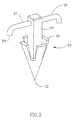
- FIG. 3is a schematic illustration of a tack for attaching a sling to a bone, in accordance with a preferred embodiment of the invention
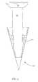
- FIG. 4is a schematic illustration of a two part tack for attaching a sling to a bone, in accordance with a preferred embodiment of the invention
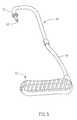
- FIG. 5is a schematic illustration of a tacker for attaching the tack of FIG. 3;
- FIG. 6is a blow-up of a tacking head part of the tacker of FIG. 5;
- FIG. 7illustrates a tack which is preloaded on a sling and mounted on a tacker, in accordance with a preferred embodiment of the invention
- FIG. 8is a schematic illustration of a two-headed tacker, in accordance with a preferred embodiment of the invention.
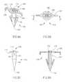
- FIGS. 9A-9Dillustrate an alternative tack, in accordance with a preferred embodiment of the invention.
- FIG. 10which corresponds to FIG. 6, illustrates the mounting of the tack of FIGS. 9A-9D on a tacker;
- FIGS. 11A-11Billustrate a variation of the tack of FIGS. 9A-9D, in accordance with a preferred embodiment of the invention
- FIGS. 12A-12Cillustrate variations of the head of a tack, in accordance with alternative preferred embodiments of the invention.
- FIGS. 13A and 13Billustrate a recessed fin tack, in accordance with a preferred embodiment of the invention
- FIGS. 13C and 13Dillustrate an expanding head tack, in accordance with a preferred embodiment of the invention
- FIG. 14is a schematic illustration of a sling grasping attachment for a stapler, in accordance with a preferred embodiment of the invention.
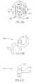
- FIG. 15Ais a schematic illustration of a tack head, such as shown in FIG. 5, including a slotted shield, in accordance with an exemplary embodiment of the invention
- FIG. 15Bis an exploded version of FIG. 15A, illustrating an alignment of the shield and the tack head, in accordance with an exemplary embodiment of the invention.
- FIG. 16is a schematic illustration of a sling-mounting implement, in accordance with an exemplary embodiment of the invention.
- FIG. 2is a schematic cut-through illustration of a pubic area during a bladder neck support operation, in accordance with a preferred embodiment of the invention.
- a sling 40is shown as being tacked directly to pubic bone 28 , by a tack 42 and being held in place by a head 44 of tack 42 .
- a shaft of tack 42pierces sling 40 .
- the slingis held against the bone by friction, caused by head 44 urging sling 40 against pubic bone 28 (possibly through intervening tissue).
- the following methodis used to attach the sling to the bone:
- a first tackis tacked (preferably through sling 40 ) into a first location on pubic bone 28 ;
- the slingis inserted between vagina 22 and bladder neck 26 or the urethra: access is preferably via one or more incisions in the vaginal wall;
- any incisions in the vaginaare preferably closed, e.g., sewn up.
- the above methodmay be varied in accordance with various preferred embodiments of the invention.
- the order of stepsmay be changed and steps may be combined.
- the two tacksmay be tacked simultaneously, using a two-headed tacker, as described for example with reference to FIG. 8 .
- the slingcomprises a strip of xenograft material.
- the slingcomprises human cadaver tissue or auto-graft material harvested from the patient.
- the slingcomprises a synthetic material, for example Dacron mesh.
- the slingis about 1 mm thick, 1-2 cm wide and 5.5 cm long, between the tacked points. It should be appreciated however, that the exact dimensions of the sling may vary responsive to the anatomy of the patient being treated. Possibly, a prior-art sling may be utilized.
- the slingis reinforced at or near portions thereof through which the tack is inserted and/or portions of the sling engaged by head 44 .
- the slingis not reinforced.
- a holeis pre-punched in the sling at or near where the insertion point of the tack.
- the holeis reinforced.
- the holemay have a shape similar to the cross-section of the shaft or it may be larger or smaller than the cross-section and/or of a different shape.
- one or more slitsare formed (and optionally reinforced) in the sling at locations where the tack is to be inserted instead of—or in addition to—punching a hole thereat.
- an elliptical or a long rectangular slotmay be cut in the strip to accommodate a plurality of tack positions.
- a plurality of pre-punched holes and/or pre-cut slitsmaybe provided for that purpose. Excess sling length is optionally removed either prior to or after deployment of the sling.
- the slingis formed of two parts, that are glued together to form a sling of a desired length, prior to or after being tacked to the bone.
- human cadaver based slingsdo not have pre-provided holes, while synthetic slings do.
- holesare cut just prior to the procedure. Alternatively, the holes are cut in a factory.
- the slinghas a smooth surface. Additionally or alternatively, at least one of the two surfaces of the sling is rough, for example to promote tissue ingrowth. Additionally or alternatively, the sling is coated with tissue growth enhancing or retarding coatings, possibly both, on different parts of the sling. Additionally or alternatively, the sling may have a plurality of barbs, apertures and/or other structures defined thereon to grasp soft tissue, for example the urethra and/or tissue between the urethra and the bone.
- the slingis pre-loaded on one or both tacks, before the tacking head is inserted into the body.
- the pre-loadingmay be performed in a factory or a work shop, where the sling is produced and/or processed. Alternatively, the pre-loading is performed at the operating table, possibly after a desired sling length is determined.
- the slingis placed between the tacking head and the bone, inside the body, so that the inserted tack will pass engage the sling before entering the bone.
- one tackis pre-mounted on the sling and is inserted into the bone. The sling is then stretched using a forceps, for example, and a second tack is inserted through the sling into the bone.
- only two tacksare used, one for each side of the sling.
- more than two tacksmay be used for example, for a wide sling (e.g., two tacks on at least on side of the sling), for an “X” shaped sling or to adjust the length of slings which are not tight enough.
- one sideis tacked and the other side is sutured or otherwise attached, for example to assist in adjustment.
- the two ends of the slingmay be tacked together at a single point on pubic bone 28 , possibly using a-single tack, thereby forming a closed loop of the sling.
- that single pointis not at the center of the pubic bone.
- a slingis used to support the bladder neck.
- a slingmay be provided to support the bladder itself, the urethra and/or other abdominal organs.
- Bladder supportalso known as cystocelle repair, generally requires a wide sling with a plurality of tacks at each end (or wide tacks).
- such a slingmay be used to correct a defect in the abdominal floor from which internal organs protrude, by supporting or suspending such organs.
- such a slingmay be used for male bladder, urethra or bladder neck suspension.
- such a slingmay be used for a tongue suspension and/or for suspending other soft tissues in the body.
- a catheteris inserted into the urethra prior to the procedure, to minimize the risk of accidentally puncturing the urethra. Additionally, such a catheter may be useful when determining a desired sling length.
- a flap-forming incision(e.g., at location 34 ) is made in the vagina prior to the first tacking or between the first and second tacking, so that the sling can be brought through the incision, under the flap and into the tissue between the vagina and the urethra.
- both tacksare tacked (with at least part of the sling still inside the vagina) and then the incision is made in the vagina. In some circumstances, no incision will be made and a significant portion of the sling will remain in the vagina.
- a sub-mucosal tunnelmay be formed in the tissue between the vagina and the urethra and the sling and/or a tacker device (described below) passed through the tunnel.
- a tacker devicedescribed below
- only a single incisionis made and the tunnel is made through that incision, for example using an endoscope.
- two incisionsare made and the tunnel formed between them.
- such tunnelingpreferably utilizes small incisions in the vagina which are either formed by the tacks passing through the vaginal wall to the bone or prepared in advance for the tacks.
- the tunneling and/or passingmay be performed before the first tacking or between the first tacking and the second tacking.
- a tackwhere the sling is attached to the tack after the tack is inserted into the bone (described below)
- such tunnelingmay even be performed after both tacks are attached to the bone.
- a small incision and/or holeis made in the vagina for the insertion of each tack.
- tissue which intervenes between the vagina and the pubic boneis moved away from the path of the tack so that the tack compresses only a minimal amount of living tissue (other than the sling) against the pubic bone.
- the tackmay create its own hole in the vaginal wall. As described above, these holes/incisions may be used as an aid to forming a sub-mucosal tunnel which bridges the incisions and is between the vagina and the urethra.
- both tacksare brought through the same, small, incision.
- the tacksare preferably attached to the superior pubis ramus (as shown in the figure).
- the slingis angled forward (when the patient is standing). If the bladder neck or the urethra descend suddenly, the neck is then held up by the sling.
- the tacksmay be attached to other parts of the pubic bone, for example its bottom or its front, as the tacks may have a flat head which does not cause contact discomfort. Additionally or alternatively, especially for bladder neck suspension procedures, it may be desirable to tack the tacks higher up on the bone or even on the abdominal fascia.
- the length of the slingis determined prior to the tacking.
- a required sling lengthmay be determined and the sling cut to size.
- any trailing portions of the sling which remain after the tackingare cut off.
- FIG. 3is a schematic illustration of a tack 50 for attaching a sling to a bone, in accordance with a preferred embodiment of the invention.
- Tack 50includes a sharp tip 52 for entering the bone, a shaft 54 which grasps the sling and a head 56 for preventing the sling from slipping off the shaft and/or for urging the sling against the bone, to prevent relative movement of the sling and the bone.
- One or more fins 58may be provided to improve the bone holding characteristics, however, they do generally interfere with insertion into bone. In some embodiments, fins 58 are flexible. In other embodiments, they are rigid.
- head 56comprises a pair of extending arms 57 .
- a protrusion 59is preferably provided, as will be shown below, sling 40 is preferably urged by protrusions 59 against the bone, however, the entire head may do the urging.
- Protrusions 59are preferably flat at their contact point with sling 40 . Alternatively, they may be pointed or roughened.
- holesare formed in sling 40 (prior to, during or after insertion), so that at least some of protrusions 59 transfix sling 40 through these holes.
- Head 56is preferably flat, however, in some embodiments it may protrude, especially for covering up sharp angles in the head.
- the armsare perpendicular to the shaft. Alternatively, they may be angled, towards the tip or away from the tip, for example, 10°, 20°, 30° or 45° away from a perpendicular to the shaft.
- the tips of the armscan mimic the behavior of protrusions 59 .
- the armsare super elastic, however, they can also function correctly if they are elastic, plastic or shape memory.
- the armsmay be in the plane of the shaft or outside of the shaft place, possibly not parallel to the shaft plane.
- a head 56is wide, for example a circular plate, a sphere or a half-sphere.
- the wide headcomprises an expanding head, which, once the tack exits the tacker, expands and/or unfolds to have a wide extent.
- the folded/unexpanded headhas a diameter similar to that of the shaft, so that the tack is suitable for use in existing anchor insertion devices.
- the unfolding headcomprises a super-elastic material which is maintained at a deformed (small head diameter) configuration by the tacker.
- the expanding headis expanded as a result of pressures applied during the insertion into the bone, for example pressure applied by an anvil portion of the tacker which forces the tack into the bone (described below).
- the diameter of the shaftis smaller than the diameter of the tip.
- the tipmay rip a larger-than-necessary hole in the sling.
- the slingis sufficiently flexible and/or elastic to accommodate the tip.
- a two part tacksuch as tack shown in FIG. 4 as a tack 60
- a head 66 and a shaft 62form a first portion, having a small diameter and on which the sling is skewered.
- a bone engagement portion 64is mounted on shaft 62 , to form a complete tack 60 .
- head 66is separate from shaft 62 .
- a commonly available staplefor example a “U” type staple may also be used to tack the sling to the pubic bone.
- the tackmay have two or more legs that engage the bone. Possibly however, the quality of the attachment is lower. For example, there may be an increased strain on the sling.
- the slingis not pierced by the tack at all. Rather the sling is provided between the two or more shafts of the tack (or legs of a staple) and is urged against the bone by the head of the tack and held thereat by friction. Preferably, the portion of the head of the tack that engages the sling is rough or jagged, to better grasp the sling. Additionally or alternatively, a stop is provided on the one or more legs, so that a minimal space is provided between the bone and the head of the tack, for example to prevent undue compression of intervening soft tissue.
- the slingmay be captured between the shaft and the bone, for example, the shaft has a depression formed in its side and the sling is held between the depression and the portion of the bone which is inside the hole made by the tack.
- the slingmay be held by holes in the head of the tack (described below).
- some preferred embodiments of the inventioncontemplate other methods of attaching the sling directly to the bone, for example using a quick setting adhesive.
- the slingis firmly attached to the bone.
- the slingmay be fixed to the tack after the tack is attached to the bone.
- a thin-headed tackis attached to the bone and only then is the sling loaded onto the tack. Thereafter, the head of the tack is attached and/or expanded, to snugly grasp the sling.
- a guiding wire or sutureis attached to the tack, so that the sling can be guided along the guide wire to the tack, for properly engaging it with the tack head.
- This wiremay then be removed from the tack, as it is does not structurally interconnect the tack and the sling.
- the slinghas a plurality of holes formed therein, to engage the shaft of the headless tack at various positions along the sling.
- FIG. 5is a schematic illustration of a tacker 70 for attaching the tack 50 of FIG. 3 to pubic bone 28 .
- Tacker 70preferably comprises a handle 72 , a body 74 , which is preferably curved and adapted for use in the vagina and a head 76 , which is urged against the pubic bone for inserting a tack.
- a tack 50is mounted at least partially externally to the head.
- the tackmay be partially or completely recessed inside head 76 .
- a flexible protecting coveris provided, which cover is pushed back from the tip of the tack to the direction of the head of the tack, by the bone when the tack is pressed against the bone.
- a cartridge of such tacksis attached to head 76 or enclosed in body 74 .
- tack 50is held onto head 76 by friction, such that, once it is engaged by the bone it can be removed from head 76 .
- a release mechanism(not shown) for preventing the release of the tack may be provided.
- such a release mechanismmay prevent the tops of fins 58 from exiting the tacker, so that the tack cannot be irrevocably attached to the bone, without activating the mechanism.
- forceis applied to the tack by pulling up handle 72 , thereby directly pulling back tack 50 into the bone.
- tacker 70may include a mechanism for advancing tack 50 into the bone, for example a lever based mechanism or a pneumatic mechanism. In devices with a release or a safety mechanism, the mechanism is preferably released prior to applying the force or during the force application, for example by a lever on handle 72 (not shown).
- FIG. 6is a blow-up of tacking head 76 part of the tacker 70 of FIG. 5.
- a slot 71is preferably formed in head 76 , to hold arms 57 for the tack configuration shown.
- FIG. 7illustrates a tack 50 , preloaded on a sling 40 and preloaded on the tacker, in accordance with a preferred embodiment of the invention.
- FIG. 15Ais a schematic illustration of a tack head 76 , such as shown in FIG. 5, including a slotted shield 1500 , in accordance with an exemplary embodiment of the invention.
- Shield 1500is provided, for example, to prevent an inadvertent contact between tack 50 and the body. As noted above, such contact can be prevented using a shield, for example a retractable shield, or, as shown here, a flexible shield.
- shield 1500buckles, so that tack 50 can contact the bone.
- shield 1500comprises a body 1502 and two or more extensions 1504 and 1506 , that define one or more slots 1508 between them.
- the slotsare provided so that a sling can be mounted on the tack and/or so that such a sling can lay flat, even with the shield in place.
- the slotsmay be narrower than, as wide or wider than a sling. Possibly, different shields are provided for different width slings.
- a single shield with a single slot width or with multiple slots having different widthsis used.
- the shieldis adapted for a particular tack size or design.
- a single shieldmay be suitable for multiple tack designs and/or sizes.
- the slotsare straight, as shown.
- the slotsmay be wedge shaped, flaring in or flaring out towards the tip of shield 1500 .
- the slotsmay be curved or piecewise linear.
- Shield 1500is shown with extension 1504 and 1506 protecting all of head 52 of tack 50 , however, they may be shorter, so some of head 52 protrudes. Alternatively or additionally, slots for arms 57 of the tack may also be provided in the shield. As shown, the shield has a diameter greater than the extent of arms 57 .
- shield 1500defines a slit or protrusion at a point 1510 at the base of the protrusions, to engage the sling. Possibly, a plurality of such slits or protrusions are defined, for example to support multiple tack sizes. Alternatively, different shields may be used for different tacks.
- FIG. 15Bis an exploded version of FIG. 15A, illustrating an alignment of shield 1500 and tack head 76 , in accordance with an exemplary embodiment of the invention.
- shield 1500is mounted on a shield-engaging portion 1514 of head 76 .
- engaging portion 1514includes a ring that matches a depression 1512 in shield 1500 .
- a directional couplingis defined between head 76 and shield 1500 , for example, by defining a planar portion 1516 in engaging portion 1514 , that matches a planar portion inside shield 1500 (not shown).
- shield 1500can be defined to have a non-rotational symmetric cross-section, for example, a rectangle or a triangle. Such a cross-section may also assist tactile sensations inside the body, using the physicians fingers.
- shield 1500is flexible.
- shield 1500may be designed to break when sufficient pressure is applied, for example, along an optional fracture line 1518 , so that the two extensions 1506 and 1504 fold out of the way.
- the broken piecesremain attached to shield 1500 , to prevent leaving foreign objects in the body.
- shield 1500comprises a rigid layer (which is broken) and a flexible layer (which holds the pieces together).
- shield 1500may be a retractable shield, for example, using a retraction mechanism (not shown) for retracting the shield when a lever or other control is operated.
- shield 1500may slide back along tack head 76 , when sufficient pressure is applied to the shield to overcome the engagement of portion 1514 .
- the shieldcannot be removed from engaging portion 1514 , without being damaged, for by portion 1514 and shield 1500 being designed to have a one time interlocking mechanism.
- Shield 1500may be permanently mounted on tack head 76 . Alternatively, it may be removable, for example for sterilization. Alternatively, for example as described above, shield 1500 may be a one time use shield.
- the slingis mounted on tack 50 , after shield 1500 is in place.
- shield 1500may be mounted after the sling, for example, by threading the free tip of the sling through the axial openings of shield 1500 .
- shield 1500may open on its side (for example if line 1518 continues along shield body 1502 ).
- shield 1500is then made radially elastic, so that it stays in place.
- a bandmay be placed on the shield, to hold it in place.
- the bandmay, for example, be removable.
- the bandmay comprise a portion of tack head 76 that engages shield 1500 .
- FIG. 16is a schematic illustration of a sling-mounting implement 1600 , in accordance with an exemplary embodiment of the invention.
- Implement 1600may be used to force a sling onto tip 52 of tack 50 .
- the slingmay be pre-perforated.
- the slingmay be pierced by tip 52 .
- implement 1600prevents a person that mounts the sling from inadvertently hurting himself on tip 52 .
- implement 1600comprises a body 1602 defining an aperture 1604 at its tip.
- Aperture 1604is sized to receive tip 52 .
- the cross-section of aperture 1604also matches tip 52 , however, this is not essential.
- implement 1600includes a handle 1608 , for example an extension of body 1602 , for example for being held by fingers.
- a finger guard 1606is provided, so that if aperture 1604 does not engage tip 52 and body 1602 slips by the tip, the tip-will not contact fingers holding handle 1608 .
- aperture 1604is wide enough so that tip 52 can be retracted after it penetrates the sling.
- tip 52is engaged by aperture 1604 and implement 1600 is removed by damaging the implement, for example splitting implement 1600 along an optional split line 1610 .
- implement 1600is adapted to hold the sling while it is being transfixed on tack 50 .
- a slot 1612is formed near aperture 1604 and sized to hold the sling.
- the tip of body 1602is made tacky.
- sling holder(s)are provided on one or more sides of body 1602 .
- body 1602is sized to fit inside shield 1500 .
- body 1602may be wide enough so that it folds shield 1500 .
- body 1602has a cross-section that matches slots 1508 in shield 1500 .
- finger guard 1606serves to prevent over-advancement of implement 1600 and the sling over tack 50 .
- one or more protrusions 1614are provided at the tip of body 1602 to prevent such an advance, by contacting head 76 or arms 57 .
- implement 1600is designed to be used with non-slotted shields, slotted shields and/or with no shield at all.
- aperture 1604is sized to engage a tip 52 of tack 50 .
- tack 50is a two part tack, as described herein, and the sling is mounted on the shaft of the tack. Tip 52 is then held by aperture 1604 and pushed, using implement 1600 (a same or different one than used for the sling) onto tack 50 .
- FIG. 8is a schematic illustration of a two-headed tacker 80 , in accordance with a preferred embodiment of the invention.
- Tacker 80includes two arms, an arm 82 and an arm 84 , each with a tacking head, 86 and 88 , respectively.
- the distance between the tacking headsmay be controlled using a screw 90 .
- Screw 90may set a maximum and/or minimum distance between the tack heads or it may fix the distance between the tack heads.
- the slingis preloaded on the tacks on the two tacking heads, the two heads are placed in the vagina and the two tacks are simultaneously tacked into the pubic bone.
- An incision for bringing the sling outside the vaginamay be made before or after the tacking.
- the slingis first brought into the desired area between the vagina and the urethra, possibly using a tunnel and then the sling is loaded (or not) onto the tacks and the tacks are attached to the bone.
- tacker 80includes only a single handle 92 , which utilizes a single mechanism for advancing both tacks (if such mechanism is provided).
- the handleincludes two separate mechanisms.
- a second handle 93is provided.
- Each of handles 92 and 93may have a separate mechanism.
- the tackermay be used to attach the tacks in series, first one and then the other.
- screw 90includes a sliding mechanism for allowing only one of the two handles to be retracted at a time without also advancing the tack of the other handle.
- setting screw 90supports fixing the length of the sling outside the body, by setting the distance between the tacking heads (and thus, typically, the tacks).
- FIGS. 9A-9Dillustrate an alternative tack 100 , in accordance with a preferred embodiment of the invention.
- FIG. 9Ais a perspective view of tack 100 , showing a tip 102 of a shaft 104 , two fins 108 and a head 104 , connected to shaft 106 by crimping an extension 112 of shaft 104 to engage a ring portion 110 of head 106 .
- head 106comprises two arms 107 , having one or more apertures 105 formed therein.
- a protrusion 109preferably wedge shaped, is provided at the end of each arm 107 .
- sling 40may be threaded through apertures 105 and/or sutured thereto.
- any knot in the sutureis placed between head 106 and the bone.
- such slingsare provided pre-sutured.
- the suturesare in the form of a loop (through which shaft 106 is preferably passed). Such a loop are preferably shortened by knotting, if needed. Alternatively, the sutures are not looped.
- Such pre-sutured slingsmay also be used for prior art sling procedures.
- FIG. 9Bis a top view of tack 100 .
- FIG. 9Cis a side view along the direction of line B—B (FIG. 9B) of tack 100 .
- FIG. 9Dis a cross-section along line B—B (FIG. 9B) illustrating the crimping of extension 112 over ring 110 .
- head 106is thus free to rotate relative to shaft 104 , however, this freedom is not essential in all embodiments and may even be explicitly blocked, for example by forming a notch in ring 110 .
- FIG. 10which corresponds to FIG. 6, illustrates the mounting on a tacker 120 of tack 100 .
- a slot 122 formed in the head of tacker 120is preferably configured so the head fits in apertures 105 , by slot 122 matching a pair of arms 124 that extend between ring 110 and the rest of head 106 .
- FIGS. 11A-13Billustrate variations in tack designs.
- FIG. 11Ais a top view of a tack 130 having four arms 132 (rather than two). Alternatively, other numbers of arms, for example three may be provided. Arms 132 are preferably symmetrically arranged and all of a same length, however, this is not essential and in some embodiments one arm may be shorter or two arms may be closer together than the other arms.
- FIG. 11Bis a cross-sectional view of a tack 140 , corresponding to FIG. 9 D and showing an alternative method of attaching a head 142 to a shaft 144 , for any type of tack, in which a slot 146 is formed in shaft 144 , to receive head 142 .
- An advantage of this methodis that an incorrectly placed tack may be corrected by removing the head and advancing the shaft so it is completely enclosed by the bone.
- the headis super-elastic or elastic, so that by applying enough force it can be mounted on the shaft or removed, without permanently distorting it.
- one time elastic or plastic headsare used, alternatively, a shape-memory material may be used.
- FIGS. 12A-12Cillustrates variations of head portions of tacks.
- FIG. 12Aillustrates a head 150 which defines a plurality of apertures 152 therein and has a plurality of protrusions 156 around its perimeter (and also possibly inside the perimeter), which are protrude towards the bone.
- Central aperture 154is preferably used to affix head 150 to a shaft of a tack. The apertures may or may not be aligned with the protrusions that most forcefully engage the sling.
- FIG. 12Billustrates, in top view, a tack 160 , which comprises spiral arms 162 , rather than straight arms as described above.
- An advantage of spiral armsis an increased flexibility of the arms, without compromising their strength.
- a pair of fins 164are also shown, for example of the type used in device 100 of FIG. 9 .
- FIG. 12Cillustrates, in top view, a tack 170 , which has only a single arm 174 .
- a pair of fins 174is also shown, perpendicular to the arm. Alternatively, the fins are parallel or oblique to the arm. Alternatively, only one fin 174 , preferably opposite arm 172 , is used.
- FIGS. 13A and 13Billustrate a recessed fin tack 180 , in accordance with a preferred embodiment of the invention.
- Tack 180comprises a head 190 attached to a shaft 182 with a tip 184 .
- At least one fin 186extend from shaft 182 , as shown in FIG. 13 A.
- a recess 188is formed in shaft 182 , to receive fin 182 during insertion into the bone, so fin 186 does not impede the insertion process (FIG. 13 B).
- the edge of the bonepresses fin 182 into recess 188 .
- shaft 182 or fin 186is formed of an elastic, shape-memory or super-elastic material, to assure that fin 186 returns to an extended configuration as shown in FIG. 13 A.
- FIGS. 13C and 13Dillustrate an expanding head tack 200 , in accordance with a preferred embodiment of the invention.
- Tack 200comprises a shaft 202 , preferably with a plurality of fins 206 at its tips.
- the head of tack 200comprises two distortable parts 210 . As shown, two or more separate arms are provided, possibly each one with a protrusion as in some of the previous embodiments. Alternatively, an extension of shaft 202 may be split.
- the headmay be narrow, as shown in FIG. 13 C.
- the headis split, for example using a cone shaped element 212 , resulting in a tack as shown in FIG.
- an advance-stop 208is provided, to prevent shaft 202 from advancing too far, especially while portions 210 are being split apart.
- a stopmay also be provided in other tack design, for example to provide a minimum distance between the head and the bone.
- the advance stopis part of the tacking head, for example being in the form of forceps or a “C” shaped element which space the head from the bone and is removed with the tacking head.
- the advance stopis formed of an bio-absorbable material.
- advance-stop 208extends away from shaft 202 , at least in one transaxial direction, more than portions 210 in their unexpanded configuration.
- a slotted insertion devicepushes against advance-stop 208 and an additional internal mandrel is provided to serve as element 212 .
- portions 210are distorted plastically.
- the portionsmay be formed of a shape-memory material (which can be optionally heated by the tacking head).
- the portionsmay be elastic or super-elastic.
- the portionsare maintained in their narrow configuration by the slotting head, which, when removed, allow them to snap open to their wide configuration.
- a bi-stable or a bimetal-mechanism for configuration changemay be used.
- Such elastic, plastic, shape-memory, super-elastic or other head distorting mechanismmay be used with any of the tack-heads described above.
- the shaft of the tackmay have a fixed or a varying profile, which can be, for example, circular, square, rectangular, triangular, fluted and/or spiral.
- the shaftmay be barbed and/or roughened.
- the tip of the tackmay be, for example, smooth, fluted, threaded, spiral, inclined on some sides and flat on the others. Alternatively or additionally, the tip may be oblique, for example as shown in FIG. 13 .
- the finsmay be, for example, of a design that is rigid or that folds back towards the shaft during insertion.
- the arms of the headmay be, for example, perpendicular to the shaft or they may be slanted. Possibly, the arm configuration is designed to match a anatomical geometry, such as a bone incline.
- the finsmay be distributed with an rotational symmetry around the shaft axis. Alternatively, they are not. Alternatively or additionally, the fins are all at a same axial position along the shaft. In some embodiments, they are not.
- FIG. 14is a schematic illustration of a sling grasping attachment 904 for a stapler 900 , in accordance with a preferred embodiment of the invention.
- a standard type staple, bone anchor and/or bone screwmay be used to attach sling 40 directly to the bone.
- Such screws and staplesusually include a stop for limiting the penetration depth into the bone, which can serve as a tack “head”, in accordance with a preferred embodiment of the invention.
- the portion of a shaft behind the stopincluding for example a threadable hole, may be filed off, especially if they are not required for the structural integrity of the bone insert.
- Attachment 904is an example of an attachment which maintains the sling in a desired position and/or orientation relative to the staple, until the staple is inserted into the bone.
- attachment 904comprises a resilient clip that urges and holds the sling against the body of stapler 900 .
- the attachmentmay be mounted over the tacking head, possibly extending the head length.
- a staple 906may pierce the sling, prior to the act of stapling.
- the tip of the stapleis recessed in the stapler and cannot engage the sling.
- other attachmentsmay be provided.
- the exact geometry of the attachmentmay be adapted for a particular stapler model and/or staple type.
- kitsin a preferred embodiment of the invention, the above described slings, tacks, shields, tackers and/or sling mounters are provided as a kit.
- a kitincludes one or more slings of possibly varying lengths and two or more tacks. Alternatively or additionally, such a kit includes instructions for using the element(s) in the kit.
Landscapes
- Health & Medical Sciences (AREA)
- Life Sciences & Earth Sciences (AREA)
- Animal Behavior & Ethology (AREA)
- General Health & Medical Sciences (AREA)
- Urology & Nephrology (AREA)
- Engineering & Computer Science (AREA)
- Biomedical Technology (AREA)
- Heart & Thoracic Surgery (AREA)
- Veterinary Medicine (AREA)
- Public Health (AREA)
- Surgery (AREA)
- Rheumatology (AREA)
- Molecular Biology (AREA)
- Medical Informatics (AREA)
- Nuclear Medicine, Radiotherapy & Molecular Imaging (AREA)
- Cardiology (AREA)
- Oral & Maxillofacial Surgery (AREA)
- Transplantation (AREA)
- Vascular Medicine (AREA)
- Prostheses (AREA)
- Surgical Instruments (AREA)
Abstract
Description
Claims (14)
Priority Applications (3)
| Application Number | Priority Date | Filing Date | Title |
|---|---|---|---|
| US09/684,108US6544273B1 (en) | 1999-01-08 | 2000-10-06 | Tack device with shield |
| US10/322,891US7226408B2 (en) | 1999-01-08 | 2002-12-18 | Tack device with shield |
| US11/689,806US8672828B2 (en) | 1999-01-08 | 2007-03-22 | Tack device with shield |
Applications Claiming Priority (4)
| Application Number | Priority Date | Filing Date | Title |
|---|---|---|---|
| IL127978 | 1999-01-08 | ||
| IL12797899AIL127978A0 (en) | 1999-01-08 | 1999-01-08 | Incontinence device |
| US09/475,870US6387041B1 (en) | 1999-01-08 | 1999-12-30 | Tack device |
| US09/684,108US6544273B1 (en) | 1999-01-08 | 2000-10-06 | Tack device with shield |
Related Parent Applications (2)
| Application Number | Title | Priority Date | Filing Date |
|---|---|---|---|
| US09/475,470Continuation-In-PartUS6352424B1 (en) | 1999-12-30 | 1999-12-30 | Extrusion die membrane assembly |
| US09/475,870Continuation-In-PartUS6387041B1 (en) | 1999-01-08 | 1999-12-30 | Tack device |
Related Child Applications (1)
| Application Number | Title | Priority Date | Filing Date |
|---|---|---|---|
| US10/322,891DivisionUS7226408B2 (en) | 1999-01-08 | 2002-12-18 | Tack device with shield |
Publications (1)
| Publication Number | Publication Date |
|---|---|
| US6544273B1true US6544273B1 (en) | 2003-04-08 |
Family
ID=26323773
Family Applications (5)
| Application Number | Title | Priority Date | Filing Date |
|---|---|---|---|
| US09/889,068Expired - LifetimeUS6730110B1 (en) | 1999-01-08 | 2000-01-06 | Tack device |
| US09/684,108Expired - LifetimeUS6544273B1 (en) | 1999-01-08 | 2000-10-06 | Tack device with shield |
| US10/322,891Expired - Fee RelatedUS7226408B2 (en) | 1999-01-08 | 2002-12-18 | Tack device with shield |
| US10/819,560Expired - Fee RelatedUS8241326B2 (en) | 1999-01-08 | 2004-04-07 | Tack device |
| US11/689,806Expired - Fee RelatedUS8672828B2 (en) | 1999-01-08 | 2007-03-22 | Tack device with shield |
Family Applications Before (1)
| Application Number | Title | Priority Date | Filing Date |
|---|---|---|---|
| US09/889,068Expired - LifetimeUS6730110B1 (en) | 1999-01-08 | 2000-01-06 | Tack device |
Family Applications After (3)
| Application Number | Title | Priority Date | Filing Date |
|---|---|---|---|
| US10/322,891Expired - Fee RelatedUS7226408B2 (en) | 1999-01-08 | 2002-12-18 | Tack device with shield |
| US10/819,560Expired - Fee RelatedUS8241326B2 (en) | 1999-01-08 | 2004-04-07 | Tack device |
| US11/689,806Expired - Fee RelatedUS8672828B2 (en) | 1999-01-08 | 2007-03-22 | Tack device with shield |
Country Status (6)
| Country | Link |
|---|---|
| US (5) | US6730110B1 (en) |
| EP (1) | EP1187557A2 (en) |
| JP (1) | JP2002534149A (en) |
| AU (1) | AU1998600A (en) |
| CA (1) | CA2351455A1 (en) |
| WO (1) | WO2000040158A2 (en) |
Cited By (135)
| Publication number | Priority date | Publication date | Assignee | Title |
|---|---|---|---|---|
| US20030009219A1 (en)* | 2001-06-29 | 2003-01-09 | Volkmar Seyr | Ligament fixation device |
| US20030135225A1 (en)* | 1999-01-08 | 2003-07-17 | Boaz Harari | Tack device with shield |
| US20030191360A1 (en)* | 2000-10-12 | 2003-10-09 | James Browning | Apparatus and method for treating female urinary incontinence |
| US20030216743A1 (en)* | 2002-05-16 | 2003-11-20 | Keith Hoffman | Bone anchor implantation device |
| US6746455B2 (en) | 1992-11-13 | 2004-06-08 | Ams Research Corporation | Bone anchor inserter with retractable shield |
| US20040172048A1 (en)* | 2001-03-30 | 2004-09-02 | James Browning | Surgical implant |
| US20040193167A1 (en)* | 2002-04-16 | 2004-09-30 | Arthrocare Corporation | Transverse suspension device |
| US6843796B2 (en) | 1999-06-04 | 2005-01-18 | Ams Research Corporation | Bone suturing device |
| US20050245932A1 (en)* | 2004-04-16 | 2005-11-03 | Fanton Gary S | Apparatus and methods for securing tissue to bone |
| US20060058578A1 (en)* | 2002-04-11 | 2006-03-16 | Gyne Ideas Limited | Apparatus and method for treating female urinary incontinence |
| US20060178673A1 (en)* | 2005-02-09 | 2006-08-10 | Arthrocare Corporation | Lockable slide hammer and gripping apparatus |
| US20060199996A1 (en)* | 2005-03-04 | 2006-09-07 | Ricardo Caraballo | Sling for supporting and occluding a tissue and method of using the same |
| US20060205995A1 (en)* | 2000-10-12 | 2006-09-14 | Gyne Ideas Limited | Apparatus and method for treating female urinary incontinence |
| US20060235516A1 (en)* | 2005-04-01 | 2006-10-19 | Arthrocare Corporation | Surgical methods for anchoring and implanting tissues |
| US20060271059A1 (en)* | 2005-05-16 | 2006-11-30 | Arthrocare Corporation | Convergent tunnel guide apparatus and method |
| US20060282083A1 (en)* | 2004-04-16 | 2006-12-14 | Fanton Gary S | Apparatus and method for securing tissue to bone with a suture |
| WO2007002012A1 (en)* | 2005-06-21 | 2007-01-04 | Ams Research Corporation | Apparatus for securing a urethral sling to pubic bone |
| US20070043255A1 (en)* | 2005-08-22 | 2007-02-22 | O'donnell Pat D | Surgical instrument for treating female pelvic prolapse |
| US20070067034A1 (en)* | 2005-08-31 | 2007-03-22 | Chirico Paul E | Implantable devices and methods for treating micro-architecture deterioration of bone tissue |
| US20070161849A1 (en)* | 2005-09-28 | 2007-07-12 | Goldberg Roger P | Apparatus and method for suspending a uterus |
| US20070162030A1 (en)* | 2006-01-06 | 2007-07-12 | Ernest Aranyi | Multi-pronged compressive absorbable tack |
| US20070255317A1 (en)* | 2006-03-22 | 2007-11-01 | Fanton Gary S | Suture passer devices and uses thereof |
| US20080196729A1 (en)* | 2004-05-21 | 2008-08-21 | Mpathy Medical Devices Limited | Implant for Treatment of Vaginal and/or Uterine Prolapse |
| US20080200751A1 (en)* | 2000-10-12 | 2008-08-21 | James Browning | Urethral support system |
| US20080228202A1 (en)* | 2007-03-16 | 2008-09-18 | Ethicon Endo-Surgery, Inc. | Endoscopic tissue approximation system |
| US20080228199A1 (en)* | 2007-03-16 | 2008-09-18 | Ethicon Endo-Surgery, Inc. | Endoscopic tissue approximation method |
| US20080243102A1 (en)* | 2007-03-27 | 2008-10-02 | Banning Gray Lary | Apparatus for segmental varicose sclerosis |
| US20080275469A1 (en)* | 2007-03-05 | 2008-11-06 | Fanton Gary S | Tack anchor systems, bone anchor systems, and methods of use |
| US20080277445A1 (en)* | 2007-05-07 | 2008-11-13 | Zergiebel Earl M | Single fire tacker instrument |
| US20080281353A1 (en)* | 2007-05-10 | 2008-11-13 | Ernest Aranyi | Powered tacker instrument |
| US20090005782A1 (en)* | 2007-03-02 | 2009-01-01 | Chirico Paul E | Fracture Fixation System and Method |
| US20090171140A1 (en)* | 2007-12-28 | 2009-07-02 | Chu Michael S H | Devices and methods for delivering female pelvic floor implants |
| US20090171143A1 (en)* | 2007-12-28 | 2009-07-02 | Chu Michael S H | Devices and method for treating pelvic dysfunctions |
| US20090171142A1 (en)* | 2007-12-28 | 2009-07-02 | Chu Michael S H | Devices and methods for treating pelvic floor dysfunctions |
| US20090216260A1 (en)* | 2008-02-20 | 2009-08-27 | Souza Alison M | Interlocking handle |
| US20090240104A1 (en)* | 2007-10-26 | 2009-09-24 | Ams Research Corporation | Surgical Articles and Methods for Treating Pelvic Conditions |
| US20090276048A1 (en)* | 2007-05-08 | 2009-11-05 | Chirico Paul E | Devices and method for bilateral support of a compression-fractured vertebral body |
| US20090287229A1 (en)* | 2008-05-19 | 2009-11-19 | Ams Research Corporation | Collapsible Tissue Anchor Device and Method |
| US20100010631A1 (en)* | 2006-05-19 | 2010-01-14 | John Fritz Otte | Method and articles for treatment of stress urinary incontinence |
| US7648055B2 (en) | 2007-03-15 | 2010-01-19 | Tyco Healthcare Group Lp | Surgical stapling apparatus with powered articulation |
| US20100069913A1 (en)* | 2005-08-31 | 2010-03-18 | Chirico Paul E | Threaded bone filling material plunger |
| US7686838B2 (en) | 2006-11-09 | 2010-03-30 | Arthrocare Corporation | External bullet anchor apparatus and method for use in surgical repair of ligament or tendon |
| US20100094079A1 (en)* | 2005-06-21 | 2010-04-15 | Ams Research Corporation | Method and Apparatus for Securing a Urethral Sling to Pubic Bone |
| US20100105979A1 (en)* | 2008-10-27 | 2010-04-29 | Ams Research Corporation | Surgical Needle and Anchor System with Retractable Features |
| US20100168748A1 (en)* | 2008-07-16 | 2010-07-01 | Knopp Peter G | Morselizer |
| US7757925B2 (en) | 2005-06-03 | 2010-07-20 | Tyco Healthcare Group Lp | Battery powered surgical instrument |
| US20100217335A1 (en)* | 2008-12-31 | 2010-08-26 | Chirico Paul E | Self-expanding bone stabilization devices |
| US20100268018A1 (en)* | 2009-04-17 | 2010-10-21 | Boston Scientific Scimed, Inc. | Delivery sleeve for pelvic floor implants |
| US7823760B2 (en) | 2007-05-01 | 2010-11-02 | Tyco Healthcare Group Lp | Powered surgical stapling device platform |
| US20110004227A1 (en)* | 1999-04-09 | 2011-01-06 | Evalve, Inc. | Fixation devices for variation in engagement of tissue |
| US7870989B2 (en) | 2005-06-03 | 2011-01-18 | Tyco Healthcare Group Lp | Surgical stapler with timer and feedback display |
| US20110034759A1 (en)* | 2006-10-26 | 2011-02-10 | Ogdahl Jason W | Surgical articles and methods for treating pelvic conditions |
| US7901404B2 (en) | 2004-01-16 | 2011-03-08 | Arthrocare Corporation | Bone harvesting device and method |
| US20110077606A1 (en)* | 2009-09-30 | 2011-03-31 | Wilcox Heather J | Male urinary incontinence device |
| US7922063B2 (en) | 2007-10-31 | 2011-04-12 | Tyco Healthcare Group, Lp | Powered surgical instrument |
| US20110112357A1 (en)* | 2006-06-16 | 2011-05-12 | Ams Research Corporation | Surgical implants, tools, and methods for treating pelvic conditions |
| US20110118837A1 (en)* | 2009-11-16 | 2011-05-19 | George Delli-Santi | Graft pulley and methods of use |
| US20110118838A1 (en)* | 2009-11-16 | 2011-05-19 | George Delli-Santi | Graft pulley and methods of use |
| US7950560B2 (en) | 2007-04-13 | 2011-05-31 | Tyco Healthcare Group Lp | Powered surgical instrument |
| US20110160527A1 (en)* | 2009-12-31 | 2011-06-30 | Ams Research Corporation | Suture-less Tissue Fixation for Implantable Device |
| US8469875B2 (en) | 2000-07-05 | 2013-06-25 | Coloplast A/S | Method and device for treating urinary incontinence |
| US8628463B2 (en) | 2006-06-22 | 2014-01-14 | Ams Research Corporation | Adjustable tension incontinence sling assemblies |
| US20140046362A1 (en)* | 2012-08-07 | 2014-02-13 | Zift Medical | Tissue Attachment Device And Method |
| US8709471B2 (en) | 2003-03-27 | 2014-04-29 | Coloplast A/S | Medicament delivery device and a method of medicament delivery |
| US8708885B2 (en) | 2007-09-21 | 2014-04-29 | Ams Research Corporation | Pelvic floor treatments and related tools and implants |
| US8800837B2 (en) | 2007-04-13 | 2014-08-12 | Covidien Lp | Powered surgical instrument |
| US8821514B2 (en) | 2009-06-08 | 2014-09-02 | Covidien Lp | Powered tack applier |
| USD721175S1 (en) | 2011-09-08 | 2015-01-13 | Ams Research Corporation | Backers for surgical indicators |
| USD721807S1 (en) | 2011-09-08 | 2015-01-27 | Ams Research Corporation | Surgical indicators |
| US9005222B2 (en) | 2002-08-02 | 2015-04-14 | Coloplast A/S | Self-anchoring sling and introducer system |
| US9078727B2 (en) | 2006-03-16 | 2015-07-14 | Boston Scientific Scimed, Inc. | System and method for treating tissue wall prolapse |
| USD736382S1 (en) | 2011-09-08 | 2015-08-11 | Ams Research Corporation | Surgical indicator with backers |
| US9125717B2 (en) | 2011-02-23 | 2015-09-08 | Ams Research Corporation | Implant tension adjustment system and method |
| US9144483B2 (en) | 2006-01-13 | 2015-09-29 | Boston Scientific Scimed, Inc. | Placing fixation devices |
| US9168120B2 (en) | 2011-09-09 | 2015-10-27 | Boston Scientific Scimed, Inc. | Medical device and methods of delivering the medical device |
| US9226809B2 (en) | 2009-02-10 | 2016-01-05 | Ams Research Corporation | Surgical articles and methods for treating urinary incontinence |
| US9345473B2 (en) | 2009-12-30 | 2016-05-24 | Astora Women's Health, Llc | Implantable sling systems and methods |
| US9381076B2 (en) | 2010-02-23 | 2016-07-05 | Boston Scientific Scimed, Inc. | Surgical articles and methods |
| US9387061B2 (en) | 2010-09-02 | 2016-07-12 | Boston Scientific Scimed, Inc. | Pelvic implants and methods of implanting the same |
| US9445881B2 (en) | 2010-02-23 | 2016-09-20 | Boston Scientific Scimed, Inc. | Surgical articles and methods |
| US9445805B2 (en) | 2009-11-16 | 2016-09-20 | Tornier, Inc. | Bone implant with convertible suture attachment |
| US9814555B2 (en) | 2013-03-12 | 2017-11-14 | Boston Scientific Scimed, Inc. | Medical device for pelvic floor repair and method of delivering the medical device |
| US9962251B2 (en) | 2013-10-17 | 2018-05-08 | Boston Scientific Scimed, Inc. | Devices and methods for delivering implants |
| US10016192B2 (en) | 2013-06-14 | 2018-07-10 | Tornier, Inc. | Suture for connecting a human or animal tissue, soft anchor and method for attaching a tissue to a bone |
| US10285694B2 (en) | 2001-10-20 | 2019-05-14 | Covidien Lp | Surgical stapler with timer and feedback display |
| US10299842B2 (en) | 2013-12-20 | 2019-05-28 | Crossroads Extremity Systems, Llc | Bone plates with dynamic elements |
| US10492841B2 (en) | 2014-07-10 | 2019-12-03 | Crossroads Extremity Systems, Llc | Bone implant and means of insertion |
| US10500027B2 (en) | 2011-06-30 | 2019-12-10 | Boston Scientific Scimed, Inc. | Implants, tools, and methods for treatments of pelvic conditions |
| US10524785B2 (en) | 2007-04-13 | 2020-01-07 | Covidien Lp | Powered surgical instrument |
| US10653507B2 (en) | 2013-07-24 | 2020-05-19 | Covidien Lp | Expanding absorbable tack |
| US10660643B2 (en) | 2012-07-30 | 2020-05-26 | Conextions, Inc. | Soft tissue repair devices, systems, and methods |
| US10660642B2 (en) | 2012-07-30 | 2020-05-26 | Conextions, Inc. | Soft tissue repair devices, systems, and methods |
| US10835241B2 (en) | 2012-07-30 | 2020-11-17 | Conextions, Inc. | Devices, systems, and methods for repairing soft tissue and attaching soft tissue to bone |
| US10945725B2 (en) | 2017-02-06 | 2021-03-16 | Crossroads Extremity Systems, Llc | Implant inserter |
| US10973509B2 (en) | 2017-12-20 | 2021-04-13 | Conextions, Inc. | Devices, systems, and methods for repairing soft tissue and attaching soft tissue to bone |
| US10987104B2 (en) | 2017-10-30 | 2021-04-27 | Covidien Lp | Apparatus for endoscopic procedures |
| US11026673B2 (en)* | 2018-05-10 | 2021-06-08 | Edwards Lifesciences Corporation | Corkscrew tissue anchor |
| US11179149B2 (en) | 2017-02-07 | 2021-11-23 | Crossroads Extremity Systems, Llc | Counter-torque implant |
| US11197734B2 (en) | 2018-10-30 | 2021-12-14 | Covidien Lp | Load sensing devices for use in surgical instruments |
| US11202635B2 (en) | 2019-02-04 | 2021-12-21 | Covidien Lp | Programmable distal tilt position of end effector for powered surgical devices |
| US11202626B2 (en) | 2014-07-10 | 2021-12-21 | Crossroads Extremity Systems, Llc | Bone implant with means for multi directional force and means of insertion |
| US11207066B2 (en) | 2017-10-30 | 2021-12-28 | Covidien Lp | Apparatus for endoscopic procedures |
| US11219461B2 (en) | 2019-03-08 | 2022-01-11 | Covidien Lp | Strain gauge stabilization in a surgical device |
| US11253252B2 (en) | 2012-07-30 | 2022-02-22 | Conextions, Inc. | Devices, systems, and methods for repairing soft tissue and attaching soft tissue to bone |
| US11259801B2 (en) | 2007-04-13 | 2022-03-01 | Covidien Lp | Powered surgical instrument |
| US11291443B2 (en) | 2005-06-03 | 2022-04-05 | Covidien Lp | Surgical stapler with timer and feedback display |
| US11311295B2 (en) | 2017-05-15 | 2022-04-26 | Covidien Lp | Adaptive powered stapling algorithm with calibration factor |
| US11317951B2 (en) | 2013-12-20 | 2022-05-03 | Crossroads Extremity Systems, Llc | Bone plates with dynamic elements |
| US11369372B2 (en) | 2018-11-28 | 2022-06-28 | Covidien Lp | Surgical stapler adapter with flexible cable assembly, flexible fingers, and contact clips |
| US11376006B2 (en) | 2019-02-06 | 2022-07-05 | Covidien Lp | End effector force measurement with digital drive circuit |
| USD961081S1 (en) | 2020-11-18 | 2022-08-16 | Crossroads Extremity Systems, Llc | Orthopedic implant |
| US11446024B2 (en) | 2012-07-30 | 2022-09-20 | Conextions, Inc. | Devices, systems, and methods for repairing soft tissue and attaching soft tissue to bone |
| US11458244B2 (en) | 2020-02-07 | 2022-10-04 | Covidien Lp | Irrigating surgical apparatus with positive pressure fluid |
| US11497490B2 (en) | 2018-07-09 | 2022-11-15 | Covidien Lp | Powered surgical devices including predictive motor control |
| US11547397B2 (en) | 2017-12-20 | 2023-01-10 | Conextions, Inc. | Devices, systems, and methods for repairing soft tissue and attaching soft tissue to bone |
| US11553913B2 (en) | 2020-02-11 | 2023-01-17 | Covidien Lp | Electrically-determining tissue cut with surgical stapling apparatus |
| US11583384B2 (en) | 2014-03-12 | 2023-02-21 | Conextions, Inc. | Devices, systems, and methods for repairing soft tissue and attaching soft tissue to bone |
| US11622768B2 (en) | 2020-07-13 | 2023-04-11 | Covidien Lp | Methods and structure for confirming proper assembly of powered surgical stapling systems |
| US11653919B2 (en) | 2020-11-24 | 2023-05-23 | Covidien Lp | Stapler line reinforcement continuity |
| US11684362B2 (en) | 2021-06-07 | 2023-06-27 | Covidien Lp | Handheld electromechanical surgical system |
| US11696822B2 (en) | 2016-09-28 | 2023-07-11 | Conextions, Inc. | Devices, systems, and methods for repairing soft tissue and attaching soft tissue to bone |
| US11701218B2 (en) | 2012-07-30 | 2023-07-18 | Conextions, Inc. | Soft tissue to bone repair devices, systems, and methods |
| US11744580B2 (en) | 2020-11-24 | 2023-09-05 | Covidien Lp | Long stapler reloads with continuous cartridge |
| US11771432B2 (en) | 2021-06-29 | 2023-10-03 | Covidien Lp | Stapling and cutting to default values in the event of strain gauge data integrity loss |
| US11832823B2 (en) | 2022-02-08 | 2023-12-05 | Covidien Lp | Determination of anvil release during anastomosis |
| US11944531B2 (en) | 2012-07-30 | 2024-04-02 | Conextions, Inc. | Devices, systems, and methods for repairing soft tissue and attaching soft tissue to bone |
| US11957334B2 (en) | 2012-07-30 | 2024-04-16 | Conextions, Inc. | Devices, systems, and methods for repairing soft tissue and attaching soft tissue to bone |
| US12016556B2 (en) | 2021-05-03 | 2024-06-25 | Covidien Lp | Handheld electromechanical surgical system |
| US12029470B2 (en) | 2020-05-21 | 2024-07-09 | Covidien Lp | Simultaneous RF monopolar calibration using a shared return electrode |
| US12059183B2 (en) | 2020-07-31 | 2024-08-13 | Crossroads Extremity Systems, Llc | Bone plates with dynamic elements and screws |
| US12102317B2 (en) | 2017-12-20 | 2024-10-01 | Conextions, Inc. | Devices, systems, and methods for repairing soft tissue and attaching soft tissue to bone |
| US12137902B2 (en) | 2018-07-25 | 2024-11-12 | Covidien Lp | Adaptive anti-twitch algorithm for powered surgical devices |
| US12161341B2 (en) | 2021-09-07 | 2024-12-10 | Covidien Lp | Slow speed staple and staple relaxation for stapling optimization |
| US12185949B2 (en) | 2017-10-30 | 2025-01-07 | Covidien Lp | Apparatus for endoscopic procedures |
| US12193884B2 (en) | 2020-11-17 | 2025-01-14 | Covidien Lp | Contactless force measurement of motor torque in powered surgical device |
Families Citing this family (69)
| Publication number | Priority date | Publication date | Assignee | Title |
|---|---|---|---|---|
| IL127978A0 (en) | 1999-01-08 | 1999-11-30 | Influence Med Tech Ltd | Incontinence device |
| US6382214B1 (en) | 1998-04-24 | 2002-05-07 | American Medical Systems, Inc. | Methods and apparatus for correction of urinary and gynecological pathologies including treatment of male incontinence and female cystocele |
| DE10060029A1 (en)* | 2000-12-01 | 2002-06-13 | Intelligent Implants Gmbh | Removable implant holder |
| US6641525B2 (en) | 2001-01-23 | 2003-11-04 | Ams Research Corporation | Sling assembly with secure and convenient attachment |
| AU785000B2 (en)* | 2001-02-26 | 2006-08-17 | Ethicon Inc. | Method of securing a graft using a graft fixation device |
| US8968178B2 (en) | 2002-03-07 | 2015-03-03 | Ams Research Corporation | Transobturator surgical articles and methods |
| US20040143343A1 (en)* | 2003-01-17 | 2004-07-22 | Grocela Joseph A. | Post-radical prostatectomy continence implant |
| EP3087949B1 (en) | 2004-06-14 | 2018-07-25 | Boston Scientific Limited | System relating to implantable supportive slings |
| US7914437B2 (en)* | 2005-02-04 | 2011-03-29 | Ams Research Corporation | Transobturator methods for installing sling to treat incontinence, and related devices |
| AU2006210494B2 (en) | 2005-02-04 | 2011-01-06 | Ams Research Corporation | Needle design for male transobturator sling |
| US8096303B2 (en) | 2005-02-08 | 2012-01-17 | Koninklijke Philips Electronics N.V | Airway implants and methods and devices for insertion and retrieval |
| US8371307B2 (en) | 2005-02-08 | 2013-02-12 | Koninklijke Philips Electronics N.V. | Methods and devices for the treatment of airway obstruction, sleep apnea and snoring |
| JP5058969B2 (en) | 2005-04-06 | 2012-10-24 | ボストン サイエンティフィック リミテッド | System, apparatus and method for suburethral support |
| WO2007008209A1 (en) | 2005-07-13 | 2007-01-18 | Boston Scientific Scimed Inc. | Snap fit sling anchor system and related methods |
| EP2974692B1 (en) | 2005-07-25 | 2019-03-13 | Boston Scientific Limited | Pelvic floor repair system |
| US8535217B2 (en) | 2005-07-26 | 2013-09-17 | Ams Research Corporation | Methods and systems for treatment of prolapse |
| WO2007018532A1 (en)* | 2005-08-03 | 2007-02-15 | Boston Scientific Scimed, Inc. | Systems, devices and methods relating to a shape resilient sling-like support for treating urinary incontinence |
| JP2009515564A (en) | 2005-08-04 | 2009-04-16 | シー・アール・バード・インコーポレイテツド | Pelvic implant system and method |
| WO2007059199A2 (en) | 2005-11-14 | 2007-05-24 | C.R. Bard, Inc. | Sling anchor system |
| US7815659B2 (en) | 2005-11-15 | 2010-10-19 | Ethicon Endo-Surgery, Inc. | Suture anchor applicator |
| JP2009528851A (en)* | 2005-12-28 | 2009-08-13 | シー・アール・バード・インコーポレイテツド | Apparatus and method for inserting an implant |
| US8059625B2 (en)* | 2006-02-03 | 2011-11-15 | Motorola Mobility, Inc. | Distributed architecture and methods for broadcast/multicast service |
| CA2908132C (en)* | 2006-02-16 | 2018-12-11 | Ams Research Corporation | Surgical articles and methods for treating pelvic conditions |
| WO2008033950A2 (en) | 2006-09-13 | 2008-03-20 | C. R. Bard, Inc. | Urethral support system |
| WO2008042438A2 (en)* | 2006-10-03 | 2008-04-10 | Boston Scientific Scimed, Inc. | Systems and devices for treating pelvic floor disorders |
| EP2081517A4 (en)* | 2006-11-06 | 2017-06-21 | Caldera Medical, Inc. | Implants and procedures for treatment of pelvic floor disorders |
| JP2010514538A (en)* | 2007-01-03 | 2010-05-06 | エーエムエス リサーチ コーポレイション | Stool attachment method for fecal incontinence and related devices |
| EP2185081B1 (en)* | 2007-07-25 | 2013-09-11 | Nicolas Bless | Bone repair eyelet |
| FR2919487B1 (en)* | 2007-07-31 | 2010-10-29 | Sofradim Production | SURGICAL BAND REEL |
| US8317675B2 (en)* | 2007-10-03 | 2012-11-27 | Boston Scientific Scimed, Inc. | Pelvic implants and delivery devices and methods of using the same |
| US8206280B2 (en) | 2007-11-13 | 2012-06-26 | C. R. Bard, Inc. | Adjustable tissue support member |
| US8727963B2 (en) | 2008-07-31 | 2014-05-20 | Ams Research Corporation | Methods and implants for treating urinary incontinence |
| KR101739304B1 (en) | 2008-08-25 | 2017-05-24 | 에이엠에스 리서치 코포레이션 | Minimally invasive implant system |
| US9017243B2 (en) | 2008-08-25 | 2015-04-28 | Ams Research Corporation | Minimally invasive implant and method |
| US8449573B2 (en) | 2008-12-05 | 2013-05-28 | Boston Scientific Scimed, Inc. | Insertion device and method for delivery of a mesh carrier |
| WO2010078591A1 (en) | 2009-01-05 | 2010-07-08 | Caldera Medical, Inc. | Implants and procedures for supporting anatomical structures for treating conditions such as incontinence |
| US8968334B2 (en) | 2009-04-17 | 2015-03-03 | Boston Scientific Scimed, Inc. | Apparatus for delivering and anchoring implantable medical devices |
| US9301750B2 (en) | 2009-11-03 | 2016-04-05 | Boston Scientific Scimed, Inc. | Device and method for delivery of mesh-based devices |
| EP2519185A4 (en) | 2009-12-30 | 2018-01-24 | Boston Scientific Scimed, Inc. | Elongate implant system and method for treating pelvic conditions |
| US9364308B2 (en) | 2009-12-30 | 2016-06-14 | Astora Women's Health, Llc | Implant systems with tensioning feedback |
| US10959840B2 (en) | 2010-01-20 | 2021-03-30 | Micro Interventional Devices, Inc. | Systems and methods for affixing a prosthesis to tissue |
| US10743854B2 (en) | 2010-01-20 | 2020-08-18 | Micro Interventional Devices, Inc. | Tissue closure device and method |
| US9980708B2 (en) | 2010-01-20 | 2018-05-29 | Micro Interventional Devices, Inc. | Tissue closure device and method |
| US10058314B2 (en) | 2010-01-20 | 2018-08-28 | Micro Interventional Devices, Inc. | Tissue closure device and method |
| US8257366B2 (en)* | 2010-02-08 | 2012-09-04 | Coloplast A/S | Digital suture fixation system |
| US20110196389A1 (en)* | 2010-02-09 | 2011-08-11 | Coloplast A/S | Digital suture fixation system |
| EP2409667B1 (en)* | 2010-07-22 | 2015-06-17 | Braun GmbH | Electric appliance for personal use |
| US10028813B2 (en) | 2010-07-22 | 2018-07-24 | Boston Scientific Scimed, Inc. | Coated pelvic implant device and method |
| US9572648B2 (en) | 2010-12-21 | 2017-02-21 | Justin M. Crank | Implantable slings and anchor systems |
| US9622848B2 (en) | 2011-02-23 | 2017-04-18 | Boston Scientific Scimed, Inc. | Urethral stent system and method |
| FR2972916A1 (en)* | 2011-03-22 | 2012-09-28 | Edouard Pelissier | IMPLANTABLE MEDICAL DEVICE FOR THE CORRECTION OF MAMMARY PTOSIS AND METHOD OF CORRECTING MAMMARY PTOSIS |
| US8808162B2 (en) | 2011-03-28 | 2014-08-19 | Ams Research Corporation | Implants, tools, and methods for treatment of pelvic conditions |
| US9089393B2 (en) | 2011-03-28 | 2015-07-28 | Ams Research Corporation | Implants, tools, and methods for treatment of pelvic conditions |
| US9492259B2 (en) | 2011-03-30 | 2016-11-15 | Astora Women's Health, Llc | Expandable implant system |
| US9113991B2 (en) | 2011-05-12 | 2015-08-25 | Boston Scientific Scimed, Inc. | Anchors for bodily implants and methods for anchoring bodily implants into a patient's body |
| US9636201B2 (en) | 2011-05-12 | 2017-05-02 | Boston Scientific Scimed, Inc. | Delivery members for delivering an implant into a body of a patient |
| US10058240B2 (en) | 2011-06-29 | 2018-08-28 | Boston Scientific Scimed, Inc. | Systems, implants, tools, and methods for treatments of pelvic conditions |
| US9351723B2 (en) | 2011-06-30 | 2016-05-31 | Astora Women's Health, Llc | Implants, tools, and methods for treatments of pelvic conditions |
| EP2734148B1 (en) | 2011-07-22 | 2019-06-05 | Boston Scientific Scimed, Inc. | Pelvic implant system |
| US9414903B2 (en) | 2011-07-22 | 2016-08-16 | Astora Women's Health, Llc | Pelvic implant system and method |
| US9492191B2 (en) | 2011-08-04 | 2016-11-15 | Astora Women's Health, Llc | Tools and methods for treatment of pelvic conditions |
| US20130035555A1 (en) | 2011-08-05 | 2013-02-07 | Alexander James A | Systems, implants, tools, and methods for treatment of pelvic conditions |
| US10098721B2 (en) | 2011-09-01 | 2018-10-16 | Boston Scientific Scimed, Inc. | Pelvic implant needle system and method |
| US10265152B2 (en) | 2011-10-13 | 2019-04-23 | Boston Scientific Scimed, Inc. | Pelvic implant sizing systems and methods |
| US9649114B2 (en) | 2012-07-24 | 2017-05-16 | Ams Research Corporation | Systems, tools, and methods for connecting to tissue |
| BR112015023551A2 (en)* | 2013-03-15 | 2017-08-22 | Micro Interventional Devices | TISSUE CLOSING DEVICE AND METHOD |
| US9707005B2 (en) | 2014-02-14 | 2017-07-18 | Ethicon Llc | Lockout mechanisms for surgical devices |
| CN109770980A (en)* | 2019-02-01 | 2019-05-21 | 杭州锐健马斯汀医疗器材有限公司 | Holdfast and half adsorbable bone anchor apparatus |
| US12232950B2 (en)* | 2020-11-02 | 2025-02-25 | Acumed Llc | Bone anchor insertion system having inserter coupling and decoupling |
Citations (79)
| Publication number | Priority date | Publication date | Assignee | Title |
|---|---|---|---|---|
| US2738790A (en) | 1954-08-12 | 1956-03-20 | George P Pilling & Son Company | Suturing instrument |
| US3580313A (en) | 1969-01-07 | 1971-05-25 | Mcknight Charles A | Surgical instrument |
| DE2305815A1 (en) | 1973-02-07 | 1974-08-08 | Kurt Seuberth | DEVICE FOR SEPARATING SURGICAL FEEDS |
| US3995619A (en) | 1975-10-14 | 1976-12-07 | Glatzer Stephen G | Combination subcutaneous suture remover, biopsy sampler and syringe |
| US4172458A (en) | 1977-11-07 | 1979-10-30 | Pereyra Armand J | Surgical ligature carrier |
| US4632100A (en) | 1985-08-29 | 1986-12-30 | Marlowe E. Goble | Suture anchor assembly |
| US4873976A (en) | 1984-02-28 | 1989-10-17 | Schreiber Saul N | Surgical fasteners and method |
| US4920986A (en) | 1986-10-14 | 1990-05-01 | Zedlani Pty. Limited | Urinary incontinence device |
| US5007894A (en) | 1989-02-10 | 1991-04-16 | Goran Enhorning | Female incontinence device |
| US5012822A (en) | 1988-10-11 | 1991-05-07 | Schwarz Gerald R | Method for controlling urinary incontinence |
| US5013292A (en) | 1989-02-24 | 1991-05-07 | R. Laborie Medical Corporation | Surgical correction of female urinary stress incontinence and kit therefor |
| US5019032A (en) | 1990-04-03 | 1991-05-28 | Robertson Jack R | Refined suspension procedure with implement for treating female stress incontinence |
| US5085661A (en) | 1990-10-29 | 1992-02-04 | Gerald Moss | Surgical fastener implantation device |
| US5123428A (en) | 1988-10-11 | 1992-06-23 | Schwarz Gerald R | Laparoscopically implanting bladder control apparatus |
| US5188636A (en) | 1992-05-07 | 1993-02-23 | Ethicon, Inc. | Purse string suture instrument |
| US5209756A (en)* | 1989-11-03 | 1993-05-11 | Bahaa Botros Seedhom | Ligament fixation staple |
| WO1993019678A2 (en) | 1991-12-03 | 1993-10-14 | Vesitec Medical, Inc. | Surgical treatment of stress urinary incontinence |
| US5256133A (en) | 1990-09-05 | 1993-10-26 | Spitz Robert M | Device for correcting stress urinary incontinence |
| US5281237A (en) | 1992-09-25 | 1994-01-25 | Gimpelson Richard J | Surgical stitching device and method of use |
| US5328077A (en) | 1992-11-19 | 1994-07-12 | Lou Ek Seng | Method and apparatus for treating female urinary incontinence |
| US5362294A (en) | 1992-09-25 | 1994-11-08 | Seitzinger Michael R | Sling for positioning internal organ during laparoscopic surgery and method of use |
| US5376097A (en) | 1991-04-05 | 1994-12-27 | Phillips; Edward H. | Surgical fastener system |
| US5386836A (en) | 1986-10-14 | 1995-02-07 | Zedlani Pty Limited | Urinary incontinence device |
| WO1995011631A1 (en) | 1993-10-28 | 1995-05-04 | Javin Pierce | A suture anchor |
| US5413598A (en) | 1993-03-25 | 1995-05-09 | C. R. Bard, Inc. | Vascular graft |
| US5439467A (en) | 1991-12-03 | 1995-08-08 | Vesica Medical, Inc. | Suture passer |
| WO1995025469A1 (en) | 1994-03-21 | 1995-09-28 | The Anspach Effort, Inc. | Fastener for attaching objects to bones |
| US5520700A (en) | 1992-11-13 | 1996-05-28 | Technion Research & Development Foundation, Ltd. | Stapler device particularly useful in medical suturing |
| US5527342A (en)* | 1993-12-14 | 1996-06-18 | Pietrzak; William S. | Method and apparatus for securing soft tissues, tendons and ligaments to bone |
| US5562689A (en) | 1993-08-20 | 1996-10-08 | United States Surgical Corporation | Apparatus and method for applying and adjusting an anchoring device |
| US5571139A (en) | 1995-05-19 | 1996-11-05 | Jenkins, Jr.; Joseph R. | Bidirectional suture anchor |
| US5643320A (en) | 1995-03-13 | 1997-07-01 | Depuy Inc. | Soft tissue anchor and method |
| US5674247A (en) | 1994-12-14 | 1997-10-07 | Influence Inc. | Staple and tread assembly particularly for use in power-driven staplers for medical suturing |
| US5683349A (en) | 1993-02-22 | 1997-11-04 | Valleylab Inc | Laparoscopic dissection tension retractor device and method |
| US5697931A (en) | 1995-06-14 | 1997-12-16 | Incont, Inc. | Apparatus and method for laparoscopic urethopexy |
| US5709708A (en) | 1997-01-31 | 1998-01-20 | Thal; Raymond | Captured-loop knotless suture anchor assembly |
| US5725541A (en) | 1996-01-22 | 1998-03-10 | The Anspach Effort, Inc. | Soft tissue fastener device |
| US5741282A (en) | 1996-01-22 | 1998-04-21 | The Anspach Effort, Inc. | Soft tissue fastener device |
| WO1998019606A1 (en) | 1996-11-08 | 1998-05-14 | Boston Scientific Corporation | Transvaginal anchor implantation device |
| WO1998042261A1 (en) | 1997-03-25 | 1998-10-01 | Ethicon, Inc. | System for anchoring tissue to bone |
| WO1998053746A1 (en) | 1997-06-02 | 1998-12-03 | Martello Jeannette M D | Soft tissue securing anchor |
| US5899909A (en) | 1994-08-30 | 1999-05-04 | Medscand Medical Ab | Surgical instrument for treating female urinary incontinence |
| US5922026A (en) | 1997-05-01 | 1999-07-13 | Origin Medsystems, Inc. | Surgical method and prosthetic strip therefor |
| US5925047A (en) | 1998-10-19 | 1999-07-20 | Third Millennium Engineering, Llc | Coupled rod, anterior vertebral body screw, and staple assembly |
| WO1999037217A1 (en)* | 1998-01-27 | 1999-07-29 | Scimed Life Systems, Inc. | Bone anchor with implantation device |
| WO1999037216A1 (en) | 1998-01-27 | 1999-07-29 | Scimed Life Systems, Inc. | Protective sheath for transvaginal anchor implantation device |
| US5944732A (en) | 1997-08-27 | 1999-08-31 | Medical Components, Inc. | Subcutaneous tunnelling device and methods of forming a subcutaneous tunnel |
| US5972000A (en) | 1992-11-13 | 1999-10-26 | Influence Medical Technologies, Ltd. | Non-linear anchor inserter device and bone anchors |
| WO1999053829A1 (en) | 1998-04-23 | 1999-10-28 | Scimed Life Systems, Inc. | Medical body access device |
| US5980558A (en) | 1997-09-30 | 1999-11-09 | Biomet Inc. | Suture anchor system |
| US5984927A (en) | 1998-03-03 | 1999-11-16 | Ethicon, Inc. | Device for sutureless attachment of soft tissue to bone |
| US5988171A (en) | 1997-06-26 | 1999-11-23 | Influence Medical Technologies, Ltd. | Methods and devices for the treatment of airway obstruction, sleep apnea and snoring |
| US5997554A (en) | 1995-06-14 | 1999-12-07 | Medworks Corporation | Surgical template and surgical method employing same |
| US6010447A (en) | 1998-07-31 | 2000-01-04 | Kardjian; Paul M. | Bladder sling |
| US6027523A (en) | 1997-10-06 | 2000-02-22 | Arthrex, Inc. | Suture anchor with attached disk |
| US6030393A (en) | 1998-09-15 | 2000-02-29 | Corlew; Earvin L. | Needle and procedure for relieving urinary incontinence |
| US6036701A (en) | 1994-01-13 | 2000-03-14 | Ethicon, Inc. | Spiral surgical tack |
| US6039686A (en) | 1997-03-18 | 2000-03-21 | Kovac; S. Robert | System and a method for the long term cure of recurrent urinary female incontinence |
| US6042534A (en) | 1997-02-13 | 2000-03-28 | Scimed Life Systems, Inc. | Stabilization sling for use in minimally invasive pelvic surgery |
| US6042536A (en) | 1998-08-13 | 2000-03-28 | Contimed, Inc. | Bladder sling |
| US6042583A (en) | 1995-06-14 | 2000-03-28 | Medworks Corporation | Bone anchor-insertion tool and surgical method employing same |
| US6048351A (en) | 1992-09-04 | 2000-04-11 | Scimed Life Systems, Inc. | Transvaginal suturing system |
| US6068591A (en) | 1998-02-17 | 2000-05-30 | Bruckner; Norman I. | Pubo-urethral support harness apparatus for percutaneous treatment of female stress urinary incontinence |
| US6099552A (en) | 1997-11-12 | 2000-08-08 | Boston Scientific Corporation | Gastrointestinal copression clips |
| US6099551A (en) | 1998-03-12 | 2000-08-08 | Shelhigh, Inc. | Pericardial strip and stapler assembly for dividing and sealing visceral tissues and method of use thereof |
| US6200330B1 (en) | 1998-11-23 | 2001-03-13 | Theodore V. Benderev | Systems for securing sutures, grafts and soft tissue to bone and periosteum |
| US20010000533A1 (en) | 1997-03-18 | 2001-04-26 | Kovac S. Robert | Transvaginal bone anchor implantation device |
| US6241736B1 (en) | 1998-05-12 | 2001-06-05 | Scimed Life Systems, Inc. | Manual bone anchor placement devices |
| US6264676B1 (en) | 1996-11-08 | 2001-07-24 | Scimed Life Systems, Inc. | Protective sheath for transvaginal anchor implantation devices |
| US20010027321A1 (en) | 1998-01-27 | 2001-10-04 | Gellman Barry N. | Bone anchor placement device with recessed anchor mount |
| US20010041895A1 (en) | 1992-11-13 | 2001-11-15 | Mordechay Beyar | Bone anchor |
| US6328744B1 (en) | 1999-06-04 | 2001-12-11 | American Medical Systems, Inc. | Bone suturing device |
| US20020038119A1 (en) | 2000-09-26 | 2002-03-28 | Scimed Life Systems, Inc. | Handle assembly for surgical instrument and method of making the assembly |
| US20020038132A1 (en) | 1999-12-10 | 2002-03-28 | Scimed Life Systems, Inc. | Detachable covering for an implantable medical device |
| US6382214B1 (en) | 1998-04-24 | 2002-05-07 | American Medical Systems, Inc. | Methods and apparatus for correction of urinary and gynecological pathologies including treatment of male incontinence and female cystocele |
| US6387041B1 (en) | 1999-01-08 | 2002-05-14 | Boaz Harari | Tack device |
| US6423072B1 (en) | 1999-05-19 | 2002-07-23 | Stephen M. Zappala | Bone anchor delivery device with an articulating head |
| US20020128681A1 (en) | 2000-11-27 | 2002-09-12 | Scimed Life Systems, Inc. | Distal protection device and method |
| US6454778B2 (en) | 1998-03-20 | 2002-09-24 | Scimed Life Systems, Inc. | Endoscopic suture systems |
Family Cites Families (79)
| Publication number | Priority date | Publication date | Assignee | Title |
|---|---|---|---|---|
| US601447A (en)* | 1898-03-29 | Harvester guard-finger | ||
| US454202A (en)* | 1891-06-16 | Safety-guard for sleeping-cars | ||
| US2002A (en)* | 1841-03-12 | Tor and planter for plowing | ||
| US2013316A (en)* | 1933-06-26 | 1935-09-03 | Schnackel S Son Inc C | Automatic valve |
| US4548202A (en) | 1983-06-20 | 1985-10-22 | Ethicon, Inc. | Mesh tissue fasteners |
| SU1225547A1 (en) | 1984-08-03 | 1986-04-23 | Московский Городской Ордена Ленина И Ордена Трудового Красного Знамени Научно-Исследовательский Институт Скорой Помощи Им.Н.В.Склифосовского | Surgical instrument |
| DE3884743T2 (en) | 1987-10-30 | 1994-01-27 | Howmedica | Device for restoring a tendon or ligament. |
| US4938760A (en) | 1989-03-29 | 1990-07-03 | American Medical Systems, Inc. | Female suspension procedure |
| US5033867A (en)* | 1990-01-11 | 1991-07-23 | Paramount Packaging Corporation | Flexible bag with pouring spout |
| US5013316A (en)* | 1990-03-26 | 1991-05-07 | Marlowe Goble E | Soft tissue anchor system |
| US5725529A (en) | 1990-09-25 | 1998-03-10 | Innovasive Devices, Inc. | Bone fastener |
| ATE174777T1 (en) | 1990-09-25 | 1999-01-15 | Innovasive Devices Inc | BONE FIXATION DEVICE |
| US5372146A (en)* | 1990-11-06 | 1994-12-13 | Branch; Thomas P. | Method and apparatus for re-approximating tissue |
| US5269783A (en) | 1991-05-13 | 1993-12-14 | United States Surgical Corporation | Device and method for repairing torn tissue |
| US5141520A (en) | 1991-10-29 | 1992-08-25 | Marlowe Goble E | Harpoon suture anchor |
| WO1993010715A2 (en) | 1991-12-03 | 1993-06-10 | Vesitec Medical, Inc. | Surgical treatment of stress urinary incontinence |
| CA2090000A1 (en) | 1992-02-24 | 1993-08-25 | H. Jonathan Tovey | Articulating mesh deployment apparatus |
| US5383904A (en) | 1992-10-13 | 1995-01-24 | United States Surgical Corporation | Stiffened surgical device |
| US6406480B1 (en) | 1992-11-13 | 2002-06-18 | American Med Syst | Bone anchor inserter with retractable shield |
| US5354292A (en) | 1993-03-02 | 1994-10-11 | Braeuer Harry L | Surgical mesh introduce with bone screw applicator for the repair of an inguinal hernia |
| US5370662A (en) | 1993-06-23 | 1994-12-06 | Kevin R. Stone | Suture anchor assembly |
| US5500000A (en) | 1993-07-01 | 1996-03-19 | United States Surgical Corporation | Soft tissue repair system and method |
| US5591206A (en) | 1993-09-30 | 1997-01-07 | Moufarr+E,Gra E+Ee Ge; Richard | Method and device for closing wounds |
| WO1996009797A1 (en) | 1994-09-28 | 1996-04-04 | Innovasive Devices, Inc. | Suture tensioning device |
| US5584860A (en)* | 1995-02-15 | 1996-12-17 | Mitek Surgical Products, Inc. | Suture anchor loader and driver |
| DE19509966A1 (en)* | 1995-03-18 | 1996-09-19 | Frank Ullrich Schuetz | Stapler and nail for surgery |
| US5591163A (en) | 1995-06-14 | 1997-01-07 | Incont, Inc. | Apparatus and method for laparoscopic urethropexy |
| US6451024B1 (en) | 1995-06-14 | 2002-09-17 | Dexterity Surgical, Inc. | Surgical method for treating urinary incontinence, and apparatus for use in same |
| US5647836A (en)* | 1995-09-28 | 1997-07-15 | Blake, Iii; Joseph W. | Method and means for treating female urinary incontinence |
| DE19544162C1 (en)* | 1995-11-17 | 1997-04-24 | Ethicon Gmbh | Implant for suspension of the bladder in urinary incontinence in women |
| DE19601477C2 (en) | 1996-01-17 | 1999-12-16 | Axel Kirsch | Fastening nail |
| US5893856A (en)* | 1996-06-12 | 1999-04-13 | Mitek Surgical Products, Inc. | Apparatus and method for binding a first layer of material to a second layer of material |
| US5782862A (en)* | 1996-07-01 | 1998-07-21 | Bonutti; Peter M. | Suture anchor inserter assembly and method |
| US5954057A (en) | 1997-02-12 | 1999-09-21 | Li Medical Technologies, Inc. | Soft tissue suspension clip, clip assembly, emplacement tool and method |
| AU6171798A (en) | 1997-02-13 | 1998-09-08 | Boston Scientific Ireland Limited, Barbados Head Office | Method and apparatus for minimally invasive pelvic surgery |
| AU6329498A (en) | 1997-02-13 | 1998-09-08 | Boston Scientific Ireland Limited, Barbados Head Office | Percutaneous and hiatal devices and methods for use in minimally invasive pelvicsurgery |
| US6019768A (en)* | 1997-11-18 | 2000-02-01 | Ethicon, Inc, | Suture anchor retriever and method for retrieving an implanted suture anchor |
| US6221005B1 (en) | 1998-02-17 | 2001-04-24 | Norman I. Bruckner | Pubo-urethral support harness apparatus for percutaneous treatment of female stress urinary incontinence with urethal hypemobility |
| US5944739A (en)* | 1998-03-12 | 1999-08-31 | Surgical Dynamics, Inc. | Suture anchor installation system |
| US6106545A (en) | 1998-04-16 | 2000-08-22 | Axya Medical, Inc. | Suture tensioning and fixation device |
| FR2777442B1 (en) | 1998-04-21 | 2000-07-28 | Tornier Sa | REVERSIBLE EXPANSION SUTURE ANCHOR |
| ATE371409T1 (en) | 1998-05-21 | 2007-09-15 | Christopher J Walshe | SYSTEM FOR FIXING TISSUE |
| US6044847A (en)* | 1998-06-23 | 2000-04-04 | Surx, Inc. | Tuck and fold fascia shortening for incontinence |
| US6648903B1 (en) | 1998-09-08 | 2003-11-18 | Pierson, Iii Raymond H. | Medical tensioning system |
| US20050004576A1 (en) | 1998-11-23 | 2005-01-06 | Benderev Theodore V. | System for securing sutures, grafts and soft tissue to bone and periosteum |
| JP2002534149A (en) | 1999-01-08 | 2002-10-15 | インフルエンス・メディカル・テクノロジーズ・リミテッド | Tack device |
| US20050283189A1 (en) | 1999-03-31 | 2005-12-22 | Rosenblatt Peter L | Systems and methods for soft tissue reconstruction |
| US6981983B1 (en) | 1999-03-31 | 2006-01-03 | Rosenblatt Peter L | System and methods for soft tissue reconstruction |
| US6273852B1 (en) | 1999-06-09 | 2001-08-14 | Ethicon, Inc. | Surgical instrument and method for treating female urinary incontinence |
| US6168611B1 (en) | 1999-09-08 | 2001-01-02 | Syed Rizvi | Suturing needle assemblies and methods of use thereof |
| FR2802798B1 (en) | 1999-12-22 | 2002-02-01 | Promedon S A | PAD STRAP FOR THE TREATMENT OF URINARY INCONTINENCE |
| US20020007222A1 (en) | 2000-04-11 | 2002-01-17 | Ashvin Desai | Method and apparatus for supporting a body organ |
| US6908473B2 (en) | 2000-04-14 | 2005-06-21 | Jeffry B. Skiba | Tissue anchoring devices, biological vessel suspending devices and systems and methods utilizing same |
| AU773391B2 (en)* | 2000-05-22 | 2004-05-27 | Jiwan Steven Dr Singh | Uterine cannula and pelvic suport for gynaecological laparoscopy |
| GB0025068D0 (en) | 2000-10-12 | 2000-11-29 | Browning Healthcare Ltd | Apparatus and method for treating female urinary incontinence |
| US20020128670A1 (en) | 2000-11-22 | 2002-09-12 | Ulf Ulmsten | Surgical instrument and method for treating female urinary incontinence |
| US6582443B2 (en) | 2000-12-27 | 2003-06-24 | Ams Research Corporation | Apparatus and methods for enhancing the functional longevity and for facilitating the implantation of medical devices |
| US20020161382A1 (en) | 2001-03-29 | 2002-10-31 | Neisz Johann J. | Implant inserted without bone anchors |
| US6602260B2 (en) | 2001-02-02 | 2003-08-05 | Ams Research Corporation | Powered bone screw device |
| US6616663B2 (en) | 2001-04-13 | 2003-09-09 | Scimed Life Systems, Inc. | Bone-anchor loading devices and methods of use therefor |
| US20020183762A1 (en) | 2001-06-01 | 2002-12-05 | Ams Research Corporation | Bone anchor inserters and methods |
| US6673010B2 (en) | 2001-10-22 | 2004-01-06 | T. A. G. Medical Products Ltd. | Biological vessel suspending assembly and systems and methods utilizing same |
| FR2831051B1 (en) | 2001-10-22 | 2004-07-30 | Johnson & Johnson Internat | MINI SUPPORT UNDER URETHRO-CERVICAL |
| US6974462B2 (en) | 2001-12-19 | 2005-12-13 | Boston Scientific Scimed, Inc. | Surgical anchor implantation device |
| CA2481275C (en) | 2002-04-11 | 2011-10-25 | Gyne Ideas Limited | Apparatus and method for treating female urinary incontinence |
| NZ538131A (en) | 2002-08-23 | 2006-12-22 | Kvinno Ct Pty Ltd | Anchoring device and its implementation |
| US20070078295A1 (en) | 2003-04-03 | 2007-04-05 | Susanne Landgrebe | Surgical implant system for treating female urinary incontinence |
| US20050199249A1 (en) | 2004-03-15 | 2005-09-15 | Karram Mickey M. | Apparatus and method for incision-free vaginal prolapse repair |
| FR2871364B1 (en) | 2004-06-10 | 2007-09-14 | Cie De Rech En Composants Impl | PROTHETIC IMPLANT OF SUPPORT UNDER URETRAL AND SURGICAL INSTRUMENT FOR ITS IMPLANTATION |
| EP3087949B1 (en) | 2004-06-14 | 2018-07-25 | Boston Scientific Limited | System relating to implantable supportive slings |
| US20050288708A1 (en) | 2004-06-25 | 2005-12-29 | Kammerer Gene W | Soft tissue fastener having integral biasing section |
| AU2005269338B2 (en) | 2004-07-28 | 2012-02-02 | Ethicon, Inc. | Minimally invasive medical implant and insertion device and method for using the same |
| JP5058969B2 (en) | 2005-04-06 | 2012-10-24 | ボストン サイエンティフィック リミテッド | System, apparatus and method for suburethral support |
| US20060252980A1 (en) | 2005-05-04 | 2006-11-09 | Arnal Kevin R | Methods and Apparatus for Securing and Tensioning a Urethral Sling to Pubic Bone |
| WO2007002071A1 (en) | 2005-06-21 | 2007-01-04 | Ams Research Corporation | Apparatus for securing a urethral sling to pubic bone |
| US8864650B2 (en) | 2005-06-21 | 2014-10-21 | Ams Research Corporation | Methods and apparatus for securing a urethral sling to a pubic bone |
| WO2007008209A1 (en) | 2005-07-13 | 2007-01-18 | Boston Scientific Scimed Inc. | Snap fit sling anchor system and related methods |
| WO2007059199A2 (en) | 2005-11-14 | 2007-05-24 | C.R. Bard, Inc. | Sling anchor system |
| WO2007137226A2 (en) | 2006-05-19 | 2007-11-29 | Ams Research Corporation | Method and articles for treatment of stress urinary incontinence |
- 2000
- 2000-01-06JPJP2000591918Apatent/JP2002534149A/enactivePending
- 2000-01-06WOPCT/IL2000/000012patent/WO2000040158A2/ennot_activeApplication Discontinuation
- 2000-01-06USUS09/889,068patent/US6730110B1/ennot_activeExpired - Lifetime
- 2000-01-06CACA002351455Apatent/CA2351455A1/ennot_activeAbandoned
- 2000-01-06EPEP00900319Apatent/EP1187557A2/ennot_activeWithdrawn
- 2000-01-06AUAU19986/00Apatent/AU1998600A/ennot_activeAbandoned
- 2000-10-06USUS09/684,108patent/US6544273B1/ennot_activeExpired - Lifetime
- 2002
- 2002-12-18USUS10/322,891patent/US7226408B2/ennot_activeExpired - Fee Related
- 2004
- 2004-04-07USUS10/819,560patent/US8241326B2/ennot_activeExpired - Fee Related
- 2007
- 2007-03-22USUS11/689,806patent/US8672828B2/ennot_activeExpired - Fee Related
Patent Citations (101)
| Publication number | Priority date | Publication date | Assignee | Title |
|---|---|---|---|---|
| US2738790A (en) | 1954-08-12 | 1956-03-20 | George P Pilling & Son Company | Suturing instrument |
| US3580313A (en) | 1969-01-07 | 1971-05-25 | Mcknight Charles A | Surgical instrument |
| DE2305815A1 (en) | 1973-02-07 | 1974-08-08 | Kurt Seuberth | DEVICE FOR SEPARATING SURGICAL FEEDS |
| US3995619A (en) | 1975-10-14 | 1976-12-07 | Glatzer Stephen G | Combination subcutaneous suture remover, biopsy sampler and syringe |
| US4172458A (en) | 1977-11-07 | 1979-10-30 | Pereyra Armand J | Surgical ligature carrier |
| US4873976A (en) | 1984-02-28 | 1989-10-17 | Schreiber Saul N | Surgical fasteners and method |
| US4632100A (en) | 1985-08-29 | 1986-12-30 | Marlowe E. Goble | Suture anchor assembly |
| US4920986A (en) | 1986-10-14 | 1990-05-01 | Zedlani Pty. Limited | Urinary incontinence device |
| US5036867A (en) | 1986-10-14 | 1991-08-06 | Zedlani Pty. Limited | Urinary incontinence device |
| US5386836A (en) | 1986-10-14 | 1995-02-07 | Zedlani Pty Limited | Urinary incontinence device |
| US5123428A (en) | 1988-10-11 | 1992-06-23 | Schwarz Gerald R | Laparoscopically implanting bladder control apparatus |
| US5012822A (en) | 1988-10-11 | 1991-05-07 | Schwarz Gerald R | Method for controlling urinary incontinence |
| US5007894A (en) | 1989-02-10 | 1991-04-16 | Goran Enhorning | Female incontinence device |
| US5013292A (en) | 1989-02-24 | 1991-05-07 | R. Laborie Medical Corporation | Surgical correction of female urinary stress incontinence and kit therefor |
| US5209756A (en)* | 1989-11-03 | 1993-05-11 | Bahaa Botros Seedhom | Ligament fixation staple |
| US5019032A (en) | 1990-04-03 | 1991-05-28 | Robertson Jack R | Refined suspension procedure with implement for treating female stress incontinence |
| US5256133A (en) | 1990-09-05 | 1993-10-26 | Spitz Robert M | Device for correcting stress urinary incontinence |
| US5085661A (en) | 1990-10-29 | 1992-02-04 | Gerald Moss | Surgical fastener implantation device |
| US5376097A (en) | 1991-04-05 | 1994-12-27 | Phillips; Edward H. | Surgical fastener system |
| US5842478A (en) | 1991-12-03 | 1998-12-01 | Boston Scientific Technology, Inc. | Method of securing a bone anchor |
| US5836314A (en) | 1991-12-03 | 1998-11-17 | Boston Scientific Technology, Inc. | Surgical treatment of stress urinary incontinence |
| US6056688A (en) | 1991-12-03 | 2000-05-02 | Boston Scientific Technology, Inc. | Device and method for transvaginally suspending the bladder neck |
| US5544664A (en) | 1991-12-03 | 1996-08-13 | Benderev; Theodore V. | Method of advancing a suture through tissue |
| WO1993019678A2 (en) | 1991-12-03 | 1993-10-14 | Vesitec Medical, Inc. | Surgical treatment of stress urinary incontinence |
| US6077216A (en) | 1991-12-03 | 2000-06-20 | Boston Scientific Technology, Inc. | Device for transvaginally suspending the bladder neck |
| US5439467A (en) | 1991-12-03 | 1995-08-08 | Vesica Medical, Inc. | Suture passer |
| US5611515A (en) | 1991-12-03 | 1997-03-18 | Boston Scientic Corporation | Bladder neck suspension procedure |
| US5860425A (en) | 1991-12-03 | 1999-01-19 | Boston Scientific Technology, Inc. | Bladder neck suspension procedure |
| US5188636A (en) | 1992-05-07 | 1993-02-23 | Ethicon, Inc. | Purse string suture instrument |
| US6048351A (en) | 1992-09-04 | 2000-04-11 | Scimed Life Systems, Inc. | Transvaginal suturing system |
| US5362294A (en) | 1992-09-25 | 1994-11-08 | Seitzinger Michael R | Sling for positioning internal organ during laparoscopic surgery and method of use |
| US5281237A (en) | 1992-09-25 | 1994-01-25 | Gimpelson Richard J | Surgical stitching device and method of use |
| US20020050277A1 (en) | 1992-11-13 | 2002-05-02 | Mordechay Beyar | Medical sling procedures and anchor insertion methods and devices |
| US20010041895A1 (en) | 1992-11-13 | 2001-11-15 | Mordechay Beyar | Bone anchor |
| US6334446B1 (en) | 1992-11-13 | 2002-01-01 | American Medical Systems, Inc. | Medical sling procedures and anchor insertion methods and devices |
| US20020035369A1 (en) | 1992-11-13 | 2002-03-21 | Mordechay Beyar | Bone anchor inserter with retractable shield |
| US5972000A (en) | 1992-11-13 | 1999-10-26 | Influence Medical Technologies, Ltd. | Non-linear anchor inserter device and bone anchors |
| US20020095064A1 (en) | 1992-11-13 | 2002-07-18 | Mordechay Beyar | Medical sling procedures and anchor insertion methods and devices |
| US20020095181A1 (en) | 1992-11-13 | 2002-07-18 | Mordechay Beyar | Medical sling procedures and anchor insertion methods and devices |
| US20020095163A1 (en) | 1992-11-13 | 2002-07-18 | Mordechay Beyar | Medical sling procedures and anchor insertion methods and devices |
| US5520700A (en) | 1992-11-13 | 1996-05-28 | Technion Research & Development Foundation, Ltd. | Stapler device particularly useful in medical suturing |
| US5807403A (en) | 1992-11-13 | 1998-09-15 | Technion Research And Development Foundation, Ltd. | Medical anchor device with suture thread and method for implantation into bone |
| US5328077A (en) | 1992-11-19 | 1994-07-12 | Lou Ek Seng | Method and apparatus for treating female urinary incontinence |
| US5683349A (en) | 1993-02-22 | 1997-11-04 | Valleylab Inc | Laparoscopic dissection tension retractor device and method |
| US5413598A (en) | 1993-03-25 | 1995-05-09 | C. R. Bard, Inc. | Vascular graft |
| US5562689A (en) | 1993-08-20 | 1996-10-08 | United States Surgical Corporation | Apparatus and method for applying and adjusting an anchoring device |
| WO1995011631A1 (en) | 1993-10-28 | 1995-05-04 | Javin Pierce | A suture anchor |
| US5527342A (en)* | 1993-12-14 | 1996-06-18 | Pietrzak; William S. | Method and apparatus for securing soft tissues, tendons and ligaments to bone |
| US6036701A (en) | 1994-01-13 | 2000-03-14 | Ethicon, Inc. | Spiral surgical tack |
| WO1995025469A1 (en) | 1994-03-21 | 1995-09-28 | The Anspach Effort, Inc. | Fastener for attaching objects to bones |
| US5899909A (en) | 1994-08-30 | 1999-05-04 | Medscand Medical Ab | Surgical instrument for treating female urinary incontinence |
| US5674247A (en) | 1994-12-14 | 1997-10-07 | Influence Inc. | Staple and tread assembly particularly for use in power-driven staplers for medical suturing |
| US5873891A (en) | 1994-12-14 | 1999-02-23 | Influence Medical Technologies, Ltd. | Staple and thread assembly particularly for use in power-driven staplers for medical suturing |
| US5643320A (en) | 1995-03-13 | 1997-07-01 | Depuy Inc. | Soft tissue anchor and method |
| US5571139A (en) | 1995-05-19 | 1996-11-05 | Jenkins, Jr.; Joseph R. | Bidirectional suture anchor |
| US5997554A (en) | 1995-06-14 | 1999-12-07 | Medworks Corporation | Surgical template and surgical method employing same |
| US5697931A (en) | 1995-06-14 | 1997-12-16 | Incont, Inc. | Apparatus and method for laparoscopic urethopexy |
| US6042583A (en) | 1995-06-14 | 2000-03-28 | Medworks Corporation | Bone anchor-insertion tool and surgical method employing same |
| US5725541A (en) | 1996-01-22 | 1998-03-10 | The Anspach Effort, Inc. | Soft tissue fastener device |
| US5741282A (en) | 1996-01-22 | 1998-04-21 | The Anspach Effort, Inc. | Soft tissue fastener device |
| US6264676B1 (en) | 1996-11-08 | 2001-07-24 | Scimed Life Systems, Inc. | Protective sheath for transvaginal anchor implantation devices |
| US6319272B1 (en) | 1996-11-08 | 2001-11-20 | Boston Scientific Corporation | Transvaginal anchor implantation device and method of use |
| WO1998019606A1 (en) | 1996-11-08 | 1998-05-14 | Boston Scientific Corporation | Transvaginal anchor implantation device |
| US6440154B2 (en) | 1996-11-08 | 2002-08-27 | Scimed Life Systems, Inc. | Protective sheath for transvaginal anchor implantation device |
| US6053935A (en) | 1996-11-08 | 2000-04-25 | Boston Scientific Corporation | Transvaginal anchor implantation device |
| US5709708A (en) | 1997-01-31 | 1998-01-20 | Thal; Raymond | Captured-loop knotless suture anchor assembly |
| US6042534A (en) | 1997-02-13 | 2000-03-28 | Scimed Life Systems, Inc. | Stabilization sling for use in minimally invasive pelvic surgery |
| US6322492B1 (en) | 1997-03-18 | 2001-11-27 | American Medical Systems, Inc. | Transvaginal method for securing a bone anchor |
| US6328686B1 (en) | 1997-03-18 | 2001-12-11 | American Medical Systems, Inc. | Transvaginal system and method for treating female urinary incontinence |
| US20020022841A1 (en) | 1997-03-18 | 2002-02-21 | Kovac S. Robert | Sling system for treating incontinence |
| US6039686A (en) | 1997-03-18 | 2000-03-21 | Kovac; S. Robert | System and a method for the long term cure of recurrent urinary female incontinence |
| US20010000533A1 (en) | 1997-03-18 | 2001-04-26 | Kovac S. Robert | Transvaginal bone anchor implantation device |
| WO1998042261A1 (en) | 1997-03-25 | 1998-10-01 | Ethicon, Inc. | System for anchoring tissue to bone |
| US5922026A (en) | 1997-05-01 | 1999-07-13 | Origin Medsystems, Inc. | Surgical method and prosthetic strip therefor |
| WO1998053746A1 (en) | 1997-06-02 | 1998-12-03 | Martello Jeannette M D | Soft tissue securing anchor |
| US5988171A (en) | 1997-06-26 | 1999-11-23 | Influence Medical Technologies, Ltd. | Methods and devices for the treatment of airway obstruction, sleep apnea and snoring |
| US5944732A (en) | 1997-08-27 | 1999-08-31 | Medical Components, Inc. | Subcutaneous tunnelling device and methods of forming a subcutaneous tunnel |
| US5980558A (en) | 1997-09-30 | 1999-11-09 | Biomet Inc. | Suture anchor system |
| US6027523A (en) | 1997-10-06 | 2000-02-22 | Arthrex, Inc. | Suture anchor with attached disk |
| US6099552A (en) | 1997-11-12 | 2000-08-08 | Boston Scientific Corporation | Gastrointestinal copression clips |
| WO1999037217A1 (en)* | 1998-01-27 | 1999-07-29 | Scimed Life Systems, Inc. | Bone anchor with implantation device |
| WO1999037216A1 (en) | 1998-01-27 | 1999-07-29 | Scimed Life Systems, Inc. | Protective sheath for transvaginal anchor implantation device |
| US20010027321A1 (en) | 1998-01-27 | 2001-10-04 | Gellman Barry N. | Bone anchor placement device with recessed anchor mount |
| US6068591A (en) | 1998-02-17 | 2000-05-30 | Bruckner; Norman I. | Pubo-urethral support harness apparatus for percutaneous treatment of female stress urinary incontinence |
| US5984927A (en) | 1998-03-03 | 1999-11-16 | Ethicon, Inc. | Device for sutureless attachment of soft tissue to bone |
| US6099551A (en) | 1998-03-12 | 2000-08-08 | Shelhigh, Inc. | Pericardial strip and stapler assembly for dividing and sealing visceral tissues and method of use thereof |
| US6454778B2 (en) | 1998-03-20 | 2002-09-24 | Scimed Life Systems, Inc. | Endoscopic suture systems |
| WO1999053829A1 (en) | 1998-04-23 | 1999-10-28 | Scimed Life Systems, Inc. | Medical body access device |
| US6382214B1 (en) | 1998-04-24 | 2002-05-07 | American Medical Systems, Inc. | Methods and apparatus for correction of urinary and gynecological pathologies including treatment of male incontinence and female cystocele |
| US6241736B1 (en) | 1998-05-12 | 2001-06-05 | Scimed Life Systems, Inc. | Manual bone anchor placement devices |
| US6010447A (en) | 1998-07-31 | 2000-01-04 | Kardjian; Paul M. | Bladder sling |
| US6042536A (en) | 1998-08-13 | 2000-03-28 | Contimed, Inc. | Bladder sling |
| US6030393A (en) | 1998-09-15 | 2000-02-29 | Corlew; Earvin L. | Needle and procedure for relieving urinary incontinence |
| US5925047A (en) | 1998-10-19 | 1999-07-20 | Third Millennium Engineering, Llc | Coupled rod, anterior vertebral body screw, and staple assembly |
| US6200330B1 (en) | 1998-11-23 | 2001-03-13 | Theodore V. Benderev | Systems for securing sutures, grafts and soft tissue to bone and periosteum |
| US6387041B1 (en) | 1999-01-08 | 2002-05-14 | Boaz Harari | Tack device |
| US6423072B1 (en) | 1999-05-19 | 2002-07-23 | Stephen M. Zappala | Bone anchor delivery device with an articulating head |
| US6328744B1 (en) | 1999-06-04 | 2001-12-11 | American Medical Systems, Inc. | Bone suturing device |
| US20020038132A1 (en) | 1999-12-10 | 2002-03-28 | Scimed Life Systems, Inc. | Detachable covering for an implantable medical device |
| US20020038119A1 (en) | 2000-09-26 | 2002-03-28 | Scimed Life Systems, Inc. | Handle assembly for surgical instrument and method of making the assembly |
| US20020128681A1 (en) | 2000-11-27 | 2002-09-12 | Scimed Life Systems, Inc. | Distal protection device and method |
Non-Patent Citations (42)
| Title |
|---|
| Beck, Peter R. et al., Treatment of Urinary Stress Incontinence With Anterior Colporrhaphy, Obstetrics and Gynecology, vol. 59 (No. 3), pp269-74 (Mar. 1982). |
| Benderev, Theodore V., MD, A Modified Percutaneous Outpatient Bladder Neck Suspension System, Journal of Urology, vol. 152, pp. 2316-2320 (Dec. 1994). |
| Benderev, Theodore V., MD, Anchor Fixation and Other Modifications of Endoscopic Bladder Neck Suspension, Urology, vol. 40, No. 5, pp. 409-418 (Nov. 1992). |
| Blaivis, J. G. et al., Pubovaginal Fascial Sling for the Treatment of Complicated Stress Urinary Incontinence, J. Urology 145(6): 1214-18 (Jun. 1991). |
| Brochure, Vesica Percutaneous Bladder Neck Stabilization Kit, Microvasive Boston Scientific Corporation (1995). |
| Burch, John C., Urethrovaginal Fixation to Cooper's Ligament for Correction of Stress Incontinence, Cystocele, and Prolapse, Am. Journal Obstetrics & Gynecology, vol. 81 (No. 2), pp. 281-290 (Feb. 1961). |
| Das, Saki et al., Laparoscopic Colpo-Suspension, The Journal of Urology, vol. 154, pp. 1119-1121 (Sep. 1995). |
| Gilja, Ivan et al., A Modified Raz Bladder Neck Suspension Operation (Transvaginal Burch), The Journal of Urology, vol. 153, pp. 1455-1457 (May 1995). |
| Gittes, Ruben F. et al., No-Incision Pubovaginal Suspension for Stress Incontinence, The Journal of Urology, vol. 138, pp. 568-570(Sep. 1987). |
| Holschneider, C. H., et al., The Modified Pereyra Procedure in Recurrent Stress Urinary Incontinence: A 15-year Review, Obstetrics & Gynecology, vol. 83, No. 4, pp. 573-578 (Apr. 1994). |
| Horbach, Nicollette S., et al., Instruments and Methods, A Suburethral Sling Procedure with Polytetrafluoroethylene for the Treatment of Genuine Stress Incontinence in Patients with Low Urethral Closure Pressure, Obstetrics & Gynecology, vol. 71, No. 4, pp. 648-652 (Apr. 1998). |
| Klutke, John James et al., The Anatomy of Stress Incontinence: Magnetic Resonance Imaging of the Female Bladder Neck and Urethra, The Journal of Urology, vol. 143, pp. 563-566 (Mar. 1990). |
| Klutke, John James et al., Transvaginal Bladder Neck Suspension to Cooper's Ligament: A Modified Pereyra Procedure, Obstetrics & Gynecology, vol. 88, No. 2, pp. 294-296 (Aug. 1996). |
| Kovac, S. Robert, et al, Pubic Bone Suburethral Stabilization Sling for Recurrent Urinary Incontinence, Obstetrics & Gynecology, vol. 89, No. 4, pp. 624-627 (Apr. 1997). |
| Kovac, S. Robert, et al, Public Bone Suburethral Stabilization Sling: A Long Term Cure for SUI?, Contemporary OB/GYN, 10 pages (Feb. 1998). |
| Kovac, S. Robert, Follow-up of the Pubic Bone Suburethral Stabilzation Sling Operation for Recurrent Urinary Incontinence (Kovac Procedure), Journal of Pelvic Surgery, pp. 156-160 (May 1999). |
| Leach, Gary E., MD, Bone Fixation Technique for Transvaginal Needle Suspension, Urology vol. XXXI, No. 5, pp. 388-390 (May 1988). |
| Leach, Gary E., MD, et al., Female Stress Urinary Incontinence Clinical Guidelines Panel Report on Surgical Management of Female Stress Urinary Incontinence, American Urological Association, vol. 158, pp. 875-880, (Sep. 1997). |
| Loughlin, Kevin R. et al., Review of An 8-Year Experience with Modifications of Endoscopic Suspension of the Bladder Neck for Female Stress Incontinence, The Journal of Urology, vol. 143, pp. 44-45 (Jan. 1990). |
| Marshall, Victor Fray et al., The Correction of Stress Incontinence by Simple Vesicourethral Suspension, Surgery, Gynecology and Obstetrics, vol. 88, pp. 509-518 (May 1949). |
| Mascio, Valenzio C., MD, Therapy of Urinary Stress Incontinence in Women Using Mitek GII Anchors, Mitek Brochure "GI Anchor System" 5 pages (Apr. 93). |
| McGuire, E. J. et al., Pubovaginal Sling Procedure for Stress Incontinence, J. Urol. 119(1): 82-4 (Jan. 1978). |
| McGuire, E.J., Abdominal Procedure for Stress Incontinence, Urol. Clin. North Am., 12(2): 285-90 (May 1985). |
| McGuire, Edware J., MD, The Sling Procedure for Urinary Stress Incontinence, Profiles in Urology, pp. 2-18 (no date). |
| McKiel, Charles F., Jr. et al., Marshall-Marchetti Procedure Modification, The Journal of Urology, vol. 96, pp. 737-739 (Nov. 1966). |
| Morgan, J. E. et al., The Marlex Sling Operation for the Treatment of Recurrent Stress Urinary Incontinence: A 16-Year Review, American Obstetrics Gynecology, vol. 151, No. 2, pp. 224-226 (Jan. 1998). |
| Parra, R. O. et al., Experience with a Simplified Technique for the Treatment of Female Stress Urinary Incontinence, British Journal of Urology, vol. 66, pp. 615-617 (1990). |
| Pereyra, Armand J. et al., Pubourethral Supports in Perspective: Modified Pereyra Procedure for Urinary Incontinence, Obstetrics and Gynecology, vol. 59, No. 5, pp. 643-648 (May 1982). |
| Precision Tack(TM) Transvaginal Anchor System, Boston Scientific Microvasive(R), 4 pages (1998). |
| Precision Tack™ Transvaginal Anchor System, Boston Scientific Microvasive®, 4 pages (1998). |
| Precision Twist(TM) Transvaginal Anchor System, Boston Scientific Microvasive(R), 2 pages (2000). |
| Precision Twist™ Transvaginal Anchor System, Boston Scientific Microvasive®, 2 pages (2000). |
| Raz, Shlomo, et al., The Raz Bladder Neck Suspension Results in 206 Patients, The Journal of Urology, pp845-46 (1992). |
| Raz, Shlomo, MD, Modified Bladder Neck Suspension for Female Stress Incontinence, Urology, vol. XVII, No. 1, pp. 82-85 (Jan. 1981). |
| Sling (advertisement), Vesica Sling Kit, Microvasive Boston Scientific Corporation, 1 page (no date). |
| Spencer, Julia R. et al., A Comparison of Endoscopic Suspension of the Vesical Neck with Suprapubic Vesicourethropexy for Treatment of Stress Urinary Incontinence, The Journal of Urology, vol. 137, pp. 441-415 (Mar. 1987). |
| Stamey, Thomas A., MD, Endoscopic Suspension of the Vesical Neck for urinary Incontinence, Surgery, Gynecology & Obstetrics, vol. 136, pp. 547-554 (Apr. 1973). |
| Ulmsten, U. et al., American Ambulatory Surgical Procedure Under Local Anesthesia for Treatment of Female Urinary Incontinence, International Urogynecology Journal, vol. 7, pp. 81-86 (May 1996). |
| Waxman, Steve et al., Advanced Urologic Surgery for Urinary Incontinence, The Female Patient, vol. 21, pp. 93-100 (Mar. 1996). |
| Webster, George D., Female Urinary Incontinence, Urology, pp. 665-679 (no date). |
| Winter, Chester C., Peripubic Urethropexy for Urinary Stress Incontinence in Women, Urology, vol. XX, No. 4, pp. 408-411 (Oct. 1982). |
| Zimmern, Phillippe E. et al., Four-Corner Bladder Neck Suspension, Vaginal Surgery for the Urologist, vol. 2, No. 1, pp. 29-36 (Apr. 1994). |
Cited By (322)
| Publication number | Priority date | Publication date | Assignee | Title |
|---|---|---|---|---|
| US6746455B2 (en) | 1992-11-13 | 2004-06-08 | Ams Research Corporation | Bone anchor inserter with retractable shield |
| US20040193215A1 (en)* | 1999-01-08 | 2004-09-30 | Boaz Harari | Tack device |
| US20030135225A1 (en)* | 1999-01-08 | 2003-07-17 | Boaz Harari | Tack device with shield |
| US7226408B2 (en)* | 1999-01-08 | 2007-06-05 | Ams Research Corporation | Tack device with shield |
| US8241326B2 (en)* | 1999-01-08 | 2012-08-14 | Ams Research Corporation | Tack device |
| US6730110B1 (en) | 1999-01-08 | 2004-05-04 | Ams Research Corporation | Tack device |
| US8672828B2 (en) | 1999-01-08 | 2014-03-18 | Ams Research Corporation | Tack device with shield |
| US8303608B2 (en)* | 1999-04-09 | 2012-11-06 | Evalve, Inc. | Fixation devices for variation in engagement of tissue |
| US20110004227A1 (en)* | 1999-04-09 | 2011-01-06 | Evalve, Inc. | Fixation devices for variation in engagement of tissue |
| US6843796B2 (en) | 1999-06-04 | 2005-01-18 | Ams Research Corporation | Bone suturing device |
| US8469875B2 (en) | 2000-07-05 | 2013-06-25 | Coloplast A/S | Method and device for treating urinary incontinence |
| US10278800B2 (en) | 2000-07-05 | 2019-05-07 | Coloplast A/S | Method and device for treating urinary incontinence |
| US8920304B2 (en) | 2000-07-05 | 2014-12-30 | Coloplast A/S | Method and device for treating urinary incontinence |
| US8821369B2 (en) | 2000-10-12 | 2014-09-02 | Colorplast A/S | Method for soft tissue anchoring with introducer |
| US8469877B2 (en) | 2000-10-12 | 2013-06-25 | Coloplast A/S | System for introducing a pelvic implant |
| US9089394B2 (en) | 2000-10-12 | 2015-07-28 | Coloplast A/S | Pelvic implant with suspending system |
| US20060205995A1 (en)* | 2000-10-12 | 2006-09-14 | Gyne Ideas Limited | Apparatus and method for treating female urinary incontinence |
| US8932202B2 (en) | 2000-10-12 | 2015-01-13 | Coloplast A/S | Incontinence implant with soft tissue anchors and length not allowing abdominal wall penetration |
| US20060041185A1 (en)* | 2000-10-12 | 2006-02-23 | Gyne Ideas Limited | Apparatus and method for treating female urinary incontinence |
| US8920308B2 (en) | 2000-10-12 | 2014-12-30 | Coloplast A/S | Surgical implant with anchor introducer channel |
| US8911347B2 (en) | 2000-10-12 | 2014-12-16 | Coloplast A/S | System and method for treating urinary incontinence |
| US8888678B2 (en) | 2000-10-12 | 2014-11-18 | Coloplast A/S | Pelvic implant with suspending system |
| US8852075B2 (en) | 2000-10-12 | 2014-10-07 | Coloplast A/S | Pelvic implant systems and methods with expandable anchors |
| US8821370B2 (en) | 2000-10-12 | 2014-09-02 | Coloplast A/S | Device, system and methods for introducing soft tissue anchors |
| US10449025B2 (en) | 2000-10-12 | 2019-10-22 | Coloplast A/S | Surgical device implantable to treat female urinary incontinence |
| US7789821B2 (en) | 2000-10-12 | 2010-09-07 | Gyne Ideas Ltd. | Apparatus and method for treating female urinary incontinence |
| US9113992B2 (en) | 2000-10-12 | 2015-08-25 | Coloplast A/S | Apparatus and method for treating urinary incontinence |
| US8801596B2 (en) | 2000-10-12 | 2014-08-12 | Coloplast A/S | Sling with support and suspending members formed from same polymer |
| US6960160B2 (en) | 2000-10-12 | 2005-11-01 | Gyneideas, Limited | Apparatus and method for treating female urinary incontinence |
| US8668635B2 (en) | 2000-10-12 | 2014-03-11 | Coloplast A/S | Pelvic implant with suspending system |
| US8574148B2 (en) | 2000-10-12 | 2013-11-05 | Coloplast A/S | System for introducing soft tissue anchors |
| US8512223B2 (en) | 2000-10-12 | 2013-08-20 | Coloplast A/S | Pelvic implant with selective locking anchor |
| US9089396B2 (en) | 2000-10-12 | 2015-07-28 | Coloplast A/S | Urinary incontinence treatment and devices |
| US10076394B2 (en) | 2000-10-12 | 2018-09-18 | Coloplast A/S | Method of treating urinary incontinence |
| US8454492B2 (en) | 2000-10-12 | 2013-06-04 | Coloplast A/S | Absorbable anchor and method for mounting mesh to tissue |
| US8449450B2 (en) | 2000-10-12 | 2013-05-28 | Coloplast A/S | Pass through introducer and sling |
| US20080200751A1 (en)* | 2000-10-12 | 2008-08-21 | James Browning | Urethral support system |
| US9968430B2 (en) | 2000-10-12 | 2018-05-15 | Coloplast A/S | Surgical device implantable to treat female urinary incontinence |
| US8273011B2 (en) | 2000-10-12 | 2012-09-25 | Coloplast A/S | Adjustable surgical implant and method for treating urinary incontinence |
| US9918817B2 (en) | 2000-10-12 | 2018-03-20 | Coloplast A/S | Method of post-operatively adjusting a urethral support in treating urinary incontinence of a woman |
| US8182413B2 (en) | 2000-10-12 | 2012-05-22 | Coloplast A/S | Method for fibrous anchoring of a pelvic support |
| US8182412B2 (en) | 2000-10-12 | 2012-05-22 | Coloplast A/S | Pelvic implant with fibrous anchor |
| US8167785B2 (en) | 2000-10-12 | 2012-05-01 | Coloplast A/S | Urethral support system |
| US8162818B2 (en) | 2000-10-12 | 2012-04-24 | Coloplast A/S | Adjustable surgical implant for pelvic anatomy |
| US8128554B2 (en) | 2000-10-12 | 2012-03-06 | Coloplast A/S | System for introducing a pelvic implant |
| US8123673B2 (en) | 2000-10-12 | 2012-02-28 | Coloplast A/S | Adjustable surgical implant for treating urinary incontinence |
| US8118728B2 (en) | 2000-10-12 | 2012-02-21 | Coloplast A/S | Method for implanting an adjustable surgical implant for treating urinary incontinence |
| US8118727B2 (en) | 2000-10-12 | 2012-02-21 | Coloplast A/S | Method for supporting pelvic anatomy |
| US8047983B2 (en) | 2000-10-12 | 2011-11-01 | Coloplast A/S | Surgical system for supporting pelvic anatomy |
| US20110237874A1 (en)* | 2000-10-12 | 2011-09-29 | Coloplast A/S | Adjustable surgical implant and method for treating urinary incontinence |
| US8007430B2 (en) | 2000-10-12 | 2011-08-30 | Coloplast A/S | Apparatus and method for treating female urinary incontinence |
| US20030191360A1 (en)* | 2000-10-12 | 2003-10-09 | James Browning | Apparatus and method for treating female urinary incontinence |
| US20100280308A1 (en)* | 2000-10-12 | 2010-11-04 | Gyne Ideas Ltd. | Apparatus and method for treating female urinary incontinence |
| US8157822B2 (en) | 2001-03-30 | 2012-04-17 | Coloplast A/S | Surgical implant and methods of use |
| US8157821B2 (en) | 2001-03-30 | 2012-04-17 | Coloplast A/S | Surgical implant |
| US8100924B2 (en) | 2001-03-30 | 2012-01-24 | Coloplast A/S | Surgical implant |
| US20100222794A1 (en)* | 2001-03-30 | 2010-09-02 | Mpathy Medical Devices Limited | Surgical Implant |
| US8632554B2 (en) | 2001-03-30 | 2014-01-21 | Coloplast A/S | Low mass density surgical implant having strands and methods of use |
| US8603119B2 (en) | 2001-03-30 | 2013-12-10 | Coloplast A/S | Surgical implant having strands and methods of use |
| US8603120B2 (en) | 2001-03-30 | 2013-12-10 | Coloplast A/S | Low mass density surgical implant and methods of use |
| US10682213B2 (en) | 2001-03-30 | 2020-06-16 | Coloplast A/S | Surgical implant consisting of non-absorbable material |
| US9248011B2 (en) | 2001-03-30 | 2016-02-02 | Coloplast A/S | Surgical implant and methods of use |
| US9943390B2 (en) | 2001-03-30 | 2018-04-17 | Coloplast A/S | Method of treating pelvic organ prolapse in a female patient by accessing a prolapsed organ trans-vaginally through a vagina |
| US20040172048A1 (en)* | 2001-03-30 | 2004-09-02 | James Browning | Surgical implant |
| US7594921B2 (en) | 2001-03-30 | 2009-09-29 | Mpathy Medical Devices Limited | Surgical implant |
| US20030009219A1 (en)* | 2001-06-29 | 2003-01-09 | Volkmar Seyr | Ligament fixation device |
| US10285694B2 (en) | 2001-10-20 | 2019-05-14 | Covidien Lp | Surgical stapler with timer and feedback display |
| US20060058578A1 (en)* | 2002-04-11 | 2006-03-16 | Gyne Ideas Limited | Apparatus and method for treating female urinary incontinence |
| US7713293B2 (en) | 2002-04-16 | 2010-05-11 | Arthrocare Corporation | Transverse suspension device |
| US20040193167A1 (en)* | 2002-04-16 | 2004-09-30 | Arthrocare Corporation | Transverse suspension device |
| US20030216743A1 (en)* | 2002-05-16 | 2003-11-20 | Keith Hoffman | Bone anchor implantation device |
| US7131973B2 (en)* | 2002-05-16 | 2006-11-07 | Boston Scientific Scimed, Inc. | Bone anchor implantation device |
| US9872750B2 (en) | 2002-08-02 | 2018-01-23 | Coloplast A/S | Self-anchoring sling and introducer system |
| US9005222B2 (en) | 2002-08-02 | 2015-04-14 | Coloplast A/S | Self-anchoring sling and introducer system |
| US9532862B2 (en) | 2002-08-02 | 2017-01-03 | Coloplast A/S | Self-anchoring sling and introducer system |
| US9532861B2 (en) | 2002-08-02 | 2017-01-03 | Coloplast A/S | Self-anchoring sling and introducer system |
| US9555168B2 (en) | 2003-03-27 | 2017-01-31 | Coloplast A/S | System for delivery of medication in treatment of disorders of the pelvis |
| US9186489B2 (en) | 2003-03-27 | 2015-11-17 | Coloplast A/S | Implantable delivery device system for delivery of a medicament to a bladder |
| US9345867B2 (en) | 2003-03-27 | 2016-05-24 | Coloplast A/S | Device implantable in tissue of a prostate gland or a bladder |
| US8709471B2 (en) | 2003-03-27 | 2014-04-29 | Coloplast A/S | Medicament delivery device and a method of medicament delivery |
| US7901404B2 (en) | 2004-01-16 | 2011-03-08 | Arthrocare Corporation | Bone harvesting device and method |
| US20060282081A1 (en)* | 2004-04-16 | 2006-12-14 | Fanton Gary S | Apparatus and method for securing tissue to bone with a suture |
| US20060282083A1 (en)* | 2004-04-16 | 2006-12-14 | Fanton Gary S | Apparatus and method for securing tissue to bone with a suture |
| US20060282082A1 (en)* | 2004-04-16 | 2006-12-14 | Fanton Gary S | Apparatus and method for securing tissue to bone with a suture |
| US20050245932A1 (en)* | 2004-04-16 | 2005-11-03 | Fanton Gary S | Apparatus and methods for securing tissue to bone |
| US20080196729A1 (en)* | 2004-05-21 | 2008-08-21 | Mpathy Medical Devices Limited | Implant for Treatment of Vaginal and/or Uterine Prolapse |
| US7975698B2 (en) | 2004-05-21 | 2011-07-12 | Coloplast A/S | Implant for treatment of vaginal and/or uterine prolapse |
| US9060838B2 (en) | 2004-05-21 | 2015-06-23 | Coloplast A/S | Tissue supported implantable device |
| US8215310B2 (en) | 2004-05-21 | 2012-07-10 | Coloplast A/S | Implant for treatment of vaginal and/or uterine prolapse |
| US10064714B2 (en) | 2004-05-21 | 2018-09-04 | Coloplast A/S | Implantable device configured to treat pelvic organ prolapse |
| US20060178673A1 (en)* | 2005-02-09 | 2006-08-10 | Arthrocare Corporation | Lockable slide hammer and gripping apparatus |
| US20060199996A1 (en)* | 2005-03-04 | 2006-09-07 | Ricardo Caraballo | Sling for supporting and occluding a tissue and method of using the same |
| US7591850B2 (en) | 2005-04-01 | 2009-09-22 | Arthrocare Corporation | Surgical methods for anchoring and implanting tissues |
| US20060235516A1 (en)* | 2005-04-01 | 2006-10-19 | Arthrocare Corporation | Surgical methods for anchoring and implanting tissues |
| US7842042B2 (en) | 2005-05-16 | 2010-11-30 | Arthrocare Corporation | Convergent tunnel guide apparatus and method |
| US20060271059A1 (en)* | 2005-05-16 | 2006-11-30 | Arthrocare Corporation | Convergent tunnel guide apparatus and method |
| US8505799B2 (en) | 2005-06-03 | 2013-08-13 | Covidien Lp | Battery powered surgical instrument |
| US7757925B2 (en) | 2005-06-03 | 2010-07-20 | Tyco Healthcare Group Lp | Battery powered surgical instrument |
| US8132705B2 (en) | 2005-06-03 | 2012-03-13 | Tyco Healthcare Group Lp | Surgical stapler with timer and feedback display |
| US8157150B2 (en) | 2005-06-03 | 2012-04-17 | Tyco Healthcare Group Lp | Surgical stapler with timer and feedback display |
| US11523826B2 (en) | 2005-06-03 | 2022-12-13 | Covidien Lp | Battery powered surgical instrument |
| US12193667B2 (en) | 2005-06-03 | 2025-01-14 | Covidien Lp | Battery powered surgical instrument |
| US9585659B2 (en) | 2005-06-03 | 2017-03-07 | Covidien Lp | Battery powered surgical instrument |
| US9370361B2 (en) | 2005-06-03 | 2016-06-21 | Covidien Lp | Surgical stapler with timer and feedback display |
| US10881404B2 (en) | 2005-06-03 | 2021-01-05 | Covidien Lp | Battery powered surgical instrument |
| US11413041B2 (en) | 2005-06-03 | 2022-08-16 | Covidien Lp | Battery powered surgical instrument |
| US8348125B2 (en) | 2005-06-03 | 2013-01-08 | Covidien Lp | Battery powered surgical instrument |
| US8505802B2 (en) | 2005-06-03 | 2013-08-13 | Covidien Lp | Surgical stapler with timer and feedback display |
| US9987005B2 (en) | 2005-06-03 | 2018-06-05 | Covidien Lp | Surgical stapler with timer and feedback display |
| US11291443B2 (en) | 2005-06-03 | 2022-04-05 | Covidien Lp | Surgical stapler with timer and feedback display |
| US10098638B2 (en) | 2005-06-03 | 2018-10-16 | Covidien Lp | Battery powered surgical instrument |
| US10188391B2 (en) | 2005-06-03 | 2019-01-29 | Covidien Lp | Battery powered surgical instrument |
| US11701118B2 (en) | 2005-06-03 | 2023-07-18 | Coviden Lp | Battery powered surgical instrument |
| US7870989B2 (en) | 2005-06-03 | 2011-01-18 | Tyco Healthcare Group Lp | Surgical stapler with timer and feedback display |
| US7909221B2 (en) | 2005-06-03 | 2011-03-22 | Tyco Healthcare Group Lp | Battery powered surgical instrument |
| US20100168505A1 (en)* | 2005-06-21 | 2010-07-01 | Ams Research Corporation | Methods and apparatus for securing a urethral sling to a pubic bone |
| US8864650B2 (en) | 2005-06-21 | 2014-10-21 | Ams Research Corporation | Methods and apparatus for securing a urethral sling to a pubic bone |
| WO2007002012A1 (en)* | 2005-06-21 | 2007-01-04 | Ams Research Corporation | Apparatus for securing a urethral sling to pubic bone |
| US20100094079A1 (en)* | 2005-06-21 | 2010-04-15 | Ams Research Corporation | Method and Apparatus for Securing a Urethral Sling to Pubic Bone |
| US9549799B2 (en) | 2005-06-21 | 2017-01-24 | Boston Scientific Scimed, Inc. | Surgical kit for securing an implantable sling in a pubic region |
| US20070043255A1 (en)* | 2005-08-22 | 2007-02-22 | O'donnell Pat D | Surgical instrument for treating female pelvic prolapse |
| US8128552B2 (en) | 2005-08-22 | 2012-03-06 | O'donnell Pat D | Surgical instrument for treating female pelvic prolapse |
| US20090234398A1 (en)* | 2005-08-31 | 2009-09-17 | Chirico Paul E | Implantable devices and methods for treating micro-architecture deterioration of bone tissue |
| US8998923B2 (en) | 2005-08-31 | 2015-04-07 | Spinealign Medical, Inc. | Threaded bone filling material plunger |
| US20070067034A1 (en)* | 2005-08-31 | 2007-03-22 | Chirico Paul E | Implantable devices and methods for treating micro-architecture deterioration of bone tissue |
| US20100069913A1 (en)* | 2005-08-31 | 2010-03-18 | Chirico Paul E | Threaded bone filling material plunger |
| US7878970B2 (en) | 2005-09-28 | 2011-02-01 | Boston Scientific Scimed, Inc. | Apparatus and method for suspending a uterus |
| US9339362B2 (en) | 2005-09-28 | 2016-05-17 | Boston Scientific Scimed, Inc. | Apparatus and method for suspending a uterus |
| US20070161849A1 (en)* | 2005-09-28 | 2007-07-12 | Goldberg Roger P | Apparatus and method for suspending a uterus |
| US7938847B2 (en) | 2006-01-04 | 2011-05-10 | Tornier, Inc. | Ring cinch assembly to attach bone to tissue |
| US20070156148A1 (en)* | 2006-01-04 | 2007-07-05 | Fanton Gary S | Ring cinch assembly to attach bone to tissue |
| US20070156149A1 (en)* | 2006-01-04 | 2007-07-05 | Fanton Gary S | Ring cinch assembly to attach bone to tissue |
| US20070156150A1 (en)* | 2006-01-04 | 2007-07-05 | Fanton Gary S | Ring cinch assembly to attach bone to tissue |
| US20070156176A1 (en)* | 2006-01-04 | 2007-07-05 | Fanton Gary S | Ring cinch assembly to attach bone to tissue |
| US20070162030A1 (en)* | 2006-01-06 | 2007-07-12 | Ernest Aranyi | Multi-pronged compressive absorbable tack |
| US9144483B2 (en) | 2006-01-13 | 2015-09-29 | Boston Scientific Scimed, Inc. | Placing fixation devices |
| US9078727B2 (en) | 2006-03-16 | 2015-07-14 | Boston Scientific Scimed, Inc. | System and method for treating tissue wall prolapse |
| US20070260259A1 (en)* | 2006-03-22 | 2007-11-08 | Fanton Gary S | Bone anchor installer and method of use |
| US8721650B2 (en) | 2006-03-22 | 2014-05-13 | Tornier, Inc. | Bone anchor installer and method of use |
| US9539001B2 (en) | 2006-03-22 | 2017-01-10 | Tornier, Inc. | Bone anchor installer and method of use |
| US20070255317A1 (en)* | 2006-03-22 | 2007-11-01 | Fanton Gary S | Suture passer devices and uses thereof |
| US20100010631A1 (en)* | 2006-05-19 | 2010-01-14 | John Fritz Otte | Method and articles for treatment of stress urinary incontinence |
| US9084664B2 (en) | 2006-05-19 | 2015-07-21 | Ams Research Corporation | Method and articles for treatment of stress urinary incontinence |
| US8834350B2 (en) | 2006-06-16 | 2014-09-16 | Ams Research Corporation | Surgical implants, tools, and methods for treating pelvic conditions |
| US20110112357A1 (en)* | 2006-06-16 | 2011-05-12 | Ams Research Corporation | Surgical implants, tools, and methods for treating pelvic conditions |
| US10271936B2 (en) | 2006-06-16 | 2019-04-30 | Boston Scientific Scimed, Inc. | Surgical implants, tools, and methods for treating pelvic conditions |
| US10441400B2 (en) | 2006-06-22 | 2019-10-15 | Boston Scientific Scimed, Inc. | Adjustable tension incontinence sling assembles |
| US8628463B2 (en) | 2006-06-22 | 2014-01-14 | Ams Research Corporation | Adjustable tension incontinence sling assemblies |
| US9375302B2 (en) | 2006-06-22 | 2016-06-28 | Astora Women's Health, Llc | Adjustable tension incontinence sling assemblies |
| US20110034759A1 (en)* | 2006-10-26 | 2011-02-10 | Ogdahl Jason W | Surgical articles and methods for treating pelvic conditions |
| US8777837B2 (en) | 2006-10-26 | 2014-07-15 | Ams Research Corporation | Surgical articles and methods for treating pelvic |
| US8388514B2 (en) | 2006-10-26 | 2013-03-05 | Ams Research Corporation | Surgical articles and methods for treating pelvic conditions |
| US9585739B2 (en) | 2006-10-26 | 2017-03-07 | Ams Research Corporation | Surgical articles and methods for treating pelvic conditions |
| US7686838B2 (en) | 2006-11-09 | 2010-03-30 | Arthrocare Corporation | External bullet anchor apparatus and method for use in surgical repair of ligament or tendon |
| US20090005782A1 (en)* | 2007-03-02 | 2009-01-01 | Chirico Paul E | Fracture Fixation System and Method |
| US8758406B2 (en) | 2007-03-05 | 2014-06-24 | Tomier, Inc. | Tack anchor systems, bone anchor systems, and methods of use |
| US20080275469A1 (en)* | 2007-03-05 | 2008-11-06 | Fanton Gary S | Tack anchor systems, bone anchor systems, and methods of use |
| US9192381B2 (en) | 2007-03-15 | 2015-11-24 | Covidien Lp | Surgical stapling apparatus with powered articulation |
| US9700314B2 (en) | 2007-03-15 | 2017-07-11 | Covidien Lp | Surgical stapling apparatus with powered articulation |
| US8240537B2 (en) | 2007-03-15 | 2012-08-14 | Tyco Healthcare Group Lp | Surgical stapling apparatus with powered articulation |
| US8006887B2 (en) | 2007-03-15 | 2011-08-30 | Tyco Healthcare Group Lp | Surgical stapling apparatus with powered articulation |
| US8419768B2 (en) | 2007-03-15 | 2013-04-16 | Covidien Lp | Surgical stapling apparatus with powered articulation |
| US7648055B2 (en) | 2007-03-15 | 2010-01-19 | Tyco Healthcare Group Lp | Surgical stapling apparatus with powered articulation |
| US8092493B2 (en) | 2007-03-15 | 2012-01-10 | Tyco Healthcare Group Lp | Surgical stapling apparatus with powered articulation |
| US20080228199A1 (en)* | 2007-03-16 | 2008-09-18 | Ethicon Endo-Surgery, Inc. | Endoscopic tissue approximation method |
| US20080228202A1 (en)* | 2007-03-16 | 2008-09-18 | Ethicon Endo-Surgery, Inc. | Endoscopic tissue approximation system |
| US20080243102A1 (en)* | 2007-03-27 | 2008-10-02 | Banning Gray Lary | Apparatus for segmental varicose sclerosis |
| US9814452B2 (en) | 2007-04-13 | 2017-11-14 | Covidien Lp | Powered surgical instrument |
| US11259802B2 (en) | 2007-04-13 | 2022-03-01 | Covidien Lp | Powered surgical instrument |
| US10524785B2 (en) | 2007-04-13 | 2020-01-07 | Covidien Lp | Powered surgical instrument |
| US11259801B2 (en) | 2007-04-13 | 2022-03-01 | Covidien Lp | Powered surgical instrument |
| US8267924B2 (en) | 2007-04-13 | 2012-09-18 | Tyco Healthcare Group Lp | Powered surgical instrument |
| US8685004B2 (en) | 2007-04-13 | 2014-04-01 | Covidien Lp | Powered surgical instrument |
| US10321902B2 (en) | 2007-04-13 | 2019-06-18 | Covidien Lp | Powered surgical instrument |
| US11464509B2 (en) | 2007-04-13 | 2022-10-11 | Covidien Lp | Powered surgical instrument |
| US10653416B2 (en) | 2007-04-13 | 2020-05-19 | Covidien Lp | Powered surgical instrument |
| US8506557B2 (en) | 2007-04-13 | 2013-08-13 | Covidien Lp | Powered surgical instrument |
| US11324499B2 (en) | 2007-04-13 | 2022-05-10 | Covidien Lp | Powered surgical instrument |
| US10357231B1 (en) | 2007-04-13 | 2019-07-23 | Covidien Lp | Powered surgical instrument |
| US8800837B2 (en) | 2007-04-13 | 2014-08-12 | Covidien Lp | Powered surgical instrument |
| US11832813B2 (en) | 2007-04-13 | 2023-12-05 | Covidien Lp | Powered surgical instrument |
| US11369370B2 (en) | 2007-04-13 | 2022-06-28 | Covidien Lp | Powered surgical instrument |
| US12303126B2 (en) | 2007-04-13 | 2025-05-20 | Covidien Lp | Powered surgical instrument |
| US10799238B2 (en) | 2007-04-13 | 2020-10-13 | Covidien Lp | Powered surgical instrument |
| US7950560B2 (en) | 2007-04-13 | 2011-05-31 | Tyco Healthcare Group Lp | Powered surgical instrument |
| US11090044B2 (en) | 2007-04-13 | 2021-08-17 | Covidien Lp | Powered surgical instrument |
| US9364222B2 (en) | 2007-05-01 | 2016-06-14 | Covidien Lp | Powered surgical stapling device platform |
| US10542983B2 (en) | 2007-05-01 | 2020-01-28 | Covidien Lp | Powered surgical stapling device platform |
| US11207069B2 (en) | 2007-05-01 | 2021-12-28 | Covidien Lp | Powered surgical stapling device platform |
| US8459521B2 (en) | 2007-05-01 | 2013-06-11 | Covidien Lp | Powered surgical stapling device platform |
| US9585664B2 (en) | 2007-05-01 | 2017-03-07 | Covidien Lp | Powered surgical stapling device platform |
| US7823760B2 (en) | 2007-05-01 | 2010-11-02 | Tyco Healthcare Group Lp | Powered surgical stapling device platform |
| US20080277445A1 (en)* | 2007-05-07 | 2008-11-13 | Zergiebel Earl M | Single fire tacker instrument |
| US20090276048A1 (en)* | 2007-05-08 | 2009-11-05 | Chirico Paul E | Devices and method for bilateral support of a compression-fractured vertebral body |
| US20080281353A1 (en)* | 2007-05-10 | 2008-11-13 | Ernest Aranyi | Powered tacker instrument |
| US8328823B2 (en) | 2007-05-10 | 2012-12-11 | Covidien Lp | Powered tacker instrument |
| US7931660B2 (en) | 2007-05-10 | 2011-04-26 | Tyco Healthcare Group Lp | Powered tacker instrument |
| US9333065B2 (en) | 2007-09-21 | 2016-05-10 | Astora Women's Health, Llc | Pelvic floor treatments and related tools and implants |
| US8708885B2 (en) | 2007-09-21 | 2014-04-29 | Ams Research Corporation | Pelvic floor treatments and related tools and implants |
| US10010394B2 (en) | 2007-09-21 | 2018-07-03 | Boston Scientific Scimed, Inc. | Pelvic floor treatments and related tools and implants |
| US8951185B2 (en) | 2007-10-26 | 2015-02-10 | Ams Research Corporation | Surgical articles and methods for treating pelvic conditions |
| US20090240104A1 (en)* | 2007-10-26 | 2009-09-24 | Ams Research Corporation | Surgical Articles and Methods for Treating Pelvic Conditions |
| US9241712B2 (en) | 2007-10-31 | 2016-01-26 | Covidien Lp | Powered surgical instrument |
| US11246589B2 (en) | 2007-10-31 | 2022-02-15 | Covidien Lp | Powered surgical instrument |
| US7922063B2 (en) | 2007-10-31 | 2011-04-12 | Tyco Healthcare Group, Lp | Powered surgical instrument |
| US9668731B2 (en) | 2007-10-31 | 2017-06-06 | Covidien Lp | Powered surgical instrument |
| US8925783B2 (en) | 2007-10-31 | 2015-01-06 | Covidien Lp | Powered surgical instrument |
| US10376262B2 (en) | 2007-10-31 | 2019-08-13 | Covidien Lp | Powered surgical instrument |
| US9113876B2 (en) | 2007-10-31 | 2015-08-25 | Covidien Lp | Powered surgical instrument |
| US11944293B2 (en) | 2007-10-31 | 2024-04-02 | Covidien Lp | Powered surgical instrument |
| US8201721B2 (en) | 2007-10-31 | 2012-06-19 | Tyco Healthcare Group Lp | Powered surgical instrument |
| US9078728B2 (en) | 2007-12-28 | 2015-07-14 | Boston Scientific Scimed, Inc. | Devices and methods for delivering female pelvic floor implants |
| US20090171140A1 (en)* | 2007-12-28 | 2009-07-02 | Chu Michael S H | Devices and methods for delivering female pelvic floor implants |
| US9974639B2 (en) | 2007-12-28 | 2018-05-22 | Boston Scientific Scimed, Inc. | Devices and methods for treating pelvic floor dysfunctions |
| US9282958B2 (en) | 2007-12-28 | 2016-03-15 | Boston Scientific Scimed, Inc. | Devices and method for treating pelvic dysfunctions |
| US11207166B2 (en) | 2007-12-28 | 2021-12-28 | Boston Scientific Scimed, Inc. | Devices and methods for treating pelvic floor dysfunctions |
| US20090171143A1 (en)* | 2007-12-28 | 2009-07-02 | Chu Michael S H | Devices and method for treating pelvic dysfunctions |
| US8430807B2 (en) | 2007-12-28 | 2013-04-30 | Boston Scientific Scimed, Inc. | Devices and methods for treating pelvic floor dysfunctions |
| US20090171142A1 (en)* | 2007-12-28 | 2009-07-02 | Chu Michael S H | Devices and methods for treating pelvic floor dysfunctions |
| US20090216260A1 (en)* | 2008-02-20 | 2009-08-27 | Souza Alison M | Interlocking handle |
| US10639138B2 (en) | 2008-02-28 | 2020-05-05 | Coloplast A/S | Method for providing support to a urethra in treating urinary incontinence |
| US20090287229A1 (en)* | 2008-05-19 | 2009-11-19 | Ams Research Corporation | Collapsible Tissue Anchor Device and Method |
| US9017382B2 (en) | 2008-05-19 | 2015-04-28 | Ams Research Corporation | Collapsible tissue anchor device and method |
| US20100168748A1 (en)* | 2008-07-16 | 2010-07-01 | Knopp Peter G | Morselizer |
| US8944990B2 (en) | 2008-10-27 | 2015-02-03 | Ams Research Corporation | Surgical needle and anchor system with retractable features |
| US20100105979A1 (en)* | 2008-10-27 | 2010-04-29 | Ams Research Corporation | Surgical Needle and Anchor System with Retractable Features |
| US20100217335A1 (en)* | 2008-12-31 | 2010-08-26 | Chirico Paul E | Self-expanding bone stabilization devices |
| US9226809B2 (en) | 2009-02-10 | 2016-01-05 | Ams Research Corporation | Surgical articles and methods for treating urinary incontinence |
| US9125716B2 (en) | 2009-04-17 | 2015-09-08 | Boston Scientific Scimed, Inc. | Delivery sleeve for pelvic floor implants |
| US20100268018A1 (en)* | 2009-04-17 | 2010-10-21 | Boston Scientific Scimed, Inc. | Delivery sleeve for pelvic floor implants |
| US9668845B2 (en) | 2009-04-17 | 2017-06-06 | Boston Scientific Scimed, Inc. | Delivery sleeve for pelvic floor implants |
| US8821514B2 (en) | 2009-06-08 | 2014-09-02 | Covidien Lp | Powered tack applier |
| US8277426B2 (en) | 2009-09-30 | 2012-10-02 | Wilcox Heather J | Male urinary incontinence device |
| US20110077606A1 (en)* | 2009-09-30 | 2011-03-31 | Wilcox Heather J | Male urinary incontinence device |
| US20110118838A1 (en)* | 2009-11-16 | 2011-05-19 | George Delli-Santi | Graft pulley and methods of use |
| US8449612B2 (en)* | 2009-11-16 | 2013-05-28 | Arthrocare Corporation | Graft pulley and methods of use |
| US20110118837A1 (en)* | 2009-11-16 | 2011-05-19 | George Delli-Santi | Graft pulley and methods of use |
| US9445805B2 (en) | 2009-11-16 | 2016-09-20 | Tornier, Inc. | Bone implant with convertible suture attachment |
| US10736619B2 (en) | 2009-11-16 | 2020-08-11 | Tornier, Inc. | Bone implant with convertible suture attachment |
| US9345473B2 (en) | 2009-12-30 | 2016-05-24 | Astora Women's Health, Llc | Implantable sling systems and methods |
| US20110160527A1 (en)* | 2009-12-31 | 2011-06-30 | Ams Research Corporation | Suture-less Tissue Fixation for Implantable Device |
| US9393091B2 (en) | 2009-12-31 | 2016-07-19 | Astora Women's Health, Llc | Suture-less tissue fixation for implantable device |
| US11446129B2 (en) | 2010-02-23 | 2022-09-20 | Boston Scientific Scimed, Inc. | Surgical articles and methods |
| US9445881B2 (en) | 2010-02-23 | 2016-09-20 | Boston Scientific Scimed, Inc. | Surgical articles and methods |
| US9381076B2 (en) | 2010-02-23 | 2016-07-05 | Boston Scientific Scimed, Inc. | Surgical articles and methods |
| US10478278B2 (en) | 2010-02-23 | 2019-11-19 | Boston Scientific Scimed, Inc. | Surgical articles and methods |
| US9387061B2 (en) | 2010-09-02 | 2016-07-12 | Boston Scientific Scimed, Inc. | Pelvic implants and methods of implanting the same |
| US9125717B2 (en) | 2011-02-23 | 2015-09-08 | Ams Research Corporation | Implant tension adjustment system and method |
| US10500027B2 (en) | 2011-06-30 | 2019-12-10 | Boston Scientific Scimed, Inc. | Implants, tools, and methods for treatments of pelvic conditions |
| USD736382S1 (en) | 2011-09-08 | 2015-08-11 | Ams Research Corporation | Surgical indicator with backers |
| USD746462S1 (en) | 2011-09-08 | 2015-12-29 | Ams Research Corporation | Surgical indicators |
| USD721807S1 (en) | 2011-09-08 | 2015-01-27 | Ams Research Corporation | Surgical indicators |
| USD721175S1 (en) | 2011-09-08 | 2015-01-13 | Ams Research Corporation | Backers for surgical indicators |
| US9168120B2 (en) | 2011-09-09 | 2015-10-27 | Boston Scientific Scimed, Inc. | Medical device and methods of delivering the medical device |
| US11253252B2 (en) | 2012-07-30 | 2022-02-22 | Conextions, Inc. | Devices, systems, and methods for repairing soft tissue and attaching soft tissue to bone |
| US11446024B2 (en) | 2012-07-30 | 2022-09-20 | Conextions, Inc. | Devices, systems, and methods for repairing soft tissue and attaching soft tissue to bone |
| US11944531B2 (en) | 2012-07-30 | 2024-04-02 | Conextions, Inc. | Devices, systems, and methods for repairing soft tissue and attaching soft tissue to bone |
| US11701218B2 (en) | 2012-07-30 | 2023-07-18 | Conextions, Inc. | Soft tissue to bone repair devices, systems, and methods |
| US10835241B2 (en) | 2012-07-30 | 2020-11-17 | Conextions, Inc. | Devices, systems, and methods for repairing soft tissue and attaching soft tissue to bone |
| US10660643B2 (en) | 2012-07-30 | 2020-05-26 | Conextions, Inc. | Soft tissue repair devices, systems, and methods |
| US10660642B2 (en) | 2012-07-30 | 2020-05-26 | Conextions, Inc. | Soft tissue repair devices, systems, and methods |
| US11980360B2 (en) | 2012-07-30 | 2024-05-14 | Conextions, Inc. | Devices, systems, and methods for repairing soft tissue and attaching soft tissue to bone |
| US11957334B2 (en) | 2012-07-30 | 2024-04-16 | Conextions, Inc. | Devices, systems, and methods for repairing soft tissue and attaching soft tissue to bone |
| US20140046362A1 (en)* | 2012-08-07 | 2014-02-13 | Zift Medical | Tissue Attachment Device And Method |
| US9814555B2 (en) | 2013-03-12 | 2017-11-14 | Boston Scientific Scimed, Inc. | Medical device for pelvic floor repair and method of delivering the medical device |
| US11083449B2 (en) | 2013-06-14 | 2021-08-10 | Howmedica Osteonics Corp. | Suture for connecting a human or animal tissue, soft anchor and method for attaching a tissue to a bone |
| US10016192B2 (en) | 2013-06-14 | 2018-07-10 | Tornier, Inc. | Suture for connecting a human or animal tissue, soft anchor and method for attaching a tissue to a bone |
| US12256919B2 (en) | 2013-06-14 | 2025-03-25 | Howmedica Osteonics Corp. | Suture for connecting a human or animal tissue, soft anchor and method for attaching a tissue to a bone |
| US10653507B2 (en) | 2013-07-24 | 2020-05-19 | Covidien Lp | Expanding absorbable tack |
| US9962251B2 (en) | 2013-10-17 | 2018-05-08 | Boston Scientific Scimed, Inc. | Devices and methods for delivering implants |
| US11109902B2 (en) | 2013-12-20 | 2021-09-07 | Crossroads Extremity Systems, Llc | Bone plates with dynamic elements |
| US11317951B2 (en) | 2013-12-20 | 2022-05-03 | Crossroads Extremity Systems, Llc | Bone plates with dynamic elements |
| US10299842B2 (en) | 2013-12-20 | 2019-05-28 | Crossroads Extremity Systems, Llc | Bone plates with dynamic elements |
| US11871899B2 (en) | 2013-12-20 | 2024-01-16 | Crossroads Extremity Systems, Llc | Bone plates with dynamic elements |
| US11583384B2 (en) | 2014-03-12 | 2023-02-21 | Conextions, Inc. | Devices, systems, and methods for repairing soft tissue and attaching soft tissue to bone |
| US11998191B2 (en) | 2014-07-10 | 2024-06-04 | Crossroads Extremity Systems, Llc | Bone implant with means for multi directional force and means of insertion |
| US11284887B2 (en) | 2014-07-10 | 2022-03-29 | Crossroads Extremity Systems, Llc | Bone implant with means for multi directional force and means of insertion |
| US10492841B2 (en) | 2014-07-10 | 2019-12-03 | Crossroads Extremity Systems, Llc | Bone implant and means of insertion |
| US11202626B2 (en) | 2014-07-10 | 2021-12-21 | Crossroads Extremity Systems, Llc | Bone implant with means for multi directional force and means of insertion |
| US11696822B2 (en) | 2016-09-28 | 2023-07-11 | Conextions, Inc. | Devices, systems, and methods for repairing soft tissue and attaching soft tissue to bone |
| US11864753B2 (en) | 2017-02-06 | 2024-01-09 | Crossroads Extremity Systems, Llc | Implant inserter |
| US10945725B2 (en) | 2017-02-06 | 2021-03-16 | Crossroads Extremity Systems, Llc | Implant inserter |
| US11179149B2 (en) | 2017-02-07 | 2021-11-23 | Crossroads Extremity Systems, Llc | Counter-torque implant |
| US11311295B2 (en) | 2017-05-15 | 2022-04-26 | Covidien Lp | Adaptive powered stapling algorithm with calibration factor |
| US11771427B2 (en) | 2017-10-30 | 2023-10-03 | Covidien Lp | Apparatus for endoscopic procedures |
| US12185949B2 (en) | 2017-10-30 | 2025-01-07 | Covidien Lp | Apparatus for endoscopic procedures |
| US11627963B2 (en) | 2017-10-30 | 2023-04-18 | Covidien Lp | Apparatus for endoscopic procedures |
| US11937813B2 (en) | 2017-10-30 | 2024-03-26 | Covidien Lp | Apparatus for endoscopic procedures |
| US10987104B2 (en) | 2017-10-30 | 2021-04-27 | Covidien Lp | Apparatus for endoscopic procedures |
| US11207066B2 (en) | 2017-10-30 | 2021-12-28 | Covidien Lp | Apparatus for endoscopic procedures |
| US10973509B2 (en) | 2017-12-20 | 2021-04-13 | Conextions, Inc. | Devices, systems, and methods for repairing soft tissue and attaching soft tissue to bone |
| US12102317B2 (en) | 2017-12-20 | 2024-10-01 | Conextions, Inc. | Devices, systems, and methods for repairing soft tissue and attaching soft tissue to bone |
| US11547397B2 (en) | 2017-12-20 | 2023-01-10 | Conextions, Inc. | Devices, systems, and methods for repairing soft tissue and attaching soft tissue to bone |
| US11969164B2 (en) | 2018-05-10 | 2024-04-30 | Edwards Lifesciences Corporation | Corkscrew tissue anchor |
| US11026673B2 (en)* | 2018-05-10 | 2021-06-08 | Edwards Lifesciences Corporation | Corkscrew tissue anchor |
| US11497490B2 (en) | 2018-07-09 | 2022-11-15 | Covidien Lp | Powered surgical devices including predictive motor control |
| US12137902B2 (en) | 2018-07-25 | 2024-11-12 | Covidien Lp | Adaptive anti-twitch algorithm for powered surgical devices |
| US11896439B2 (en) | 2018-10-30 | 2024-02-13 | Covidien Lp | Load sensing devices for use in surgical instruments |
| US11197734B2 (en) | 2018-10-30 | 2021-12-14 | Covidien Lp | Load sensing devices for use in surgical instruments |
| US11369372B2 (en) | 2018-11-28 | 2022-06-28 | Covidien Lp | Surgical stapler adapter with flexible cable assembly, flexible fingers, and contact clips |
| US12029422B2 (en) | 2018-11-28 | 2024-07-09 | Covidien Lp | Surgical stapler adapter with flexible cable assembly, flexible fingers, and contact clips |
| US11202635B2 (en) | 2019-02-04 | 2021-12-21 | Covidien Lp | Programmable distal tilt position of end effector for powered surgical devices |
| US11723664B2 (en) | 2019-02-04 | 2023-08-15 | Covidien Lp | Programmable distal tilt position of end effector for powered surgical devices |
| US11950783B2 (en) | 2019-02-06 | 2024-04-09 | Covidien Lp | End effector force measurement with digital drive circuit |
| US11376006B2 (en) | 2019-02-06 | 2022-07-05 | Covidien Lp | End effector force measurement with digital drive circuit |
| US11219461B2 (en) | 2019-03-08 | 2022-01-11 | Covidien Lp | Strain gauge stabilization in a surgical device |
| US11458244B2 (en) | 2020-02-07 | 2022-10-04 | Covidien Lp | Irrigating surgical apparatus with positive pressure fluid |
| US11553913B2 (en) | 2020-02-11 | 2023-01-17 | Covidien Lp | Electrically-determining tissue cut with surgical stapling apparatus |
| US12029470B2 (en) | 2020-05-21 | 2024-07-09 | Covidien Lp | Simultaneous RF monopolar calibration using a shared return electrode |
| US12029428B2 (en) | 2020-07-13 | 2024-07-09 | Covidien Lp | Methods and structure for confirming proper assembly of powered surgical stapling systems |
| US11622768B2 (en) | 2020-07-13 | 2023-04-11 | Covidien Lp | Methods and structure for confirming proper assembly of powered surgical stapling systems |
| US12059183B2 (en) | 2020-07-31 | 2024-08-13 | Crossroads Extremity Systems, Llc | Bone plates with dynamic elements and screws |
| US12193884B2 (en) | 2020-11-17 | 2025-01-14 | Covidien Lp | Contactless force measurement of motor torque in powered surgical device |
| USD961081S1 (en) | 2020-11-18 | 2022-08-16 | Crossroads Extremity Systems, Llc | Orthopedic implant |
| US12064108B2 (en) | 2020-11-24 | 2024-08-20 | Covidien Lp | Long stapler reloads with continuous cartridge |
| US11653919B2 (en) | 2020-11-24 | 2023-05-23 | Covidien Lp | Stapler line reinforcement continuity |
| US11744580B2 (en) | 2020-11-24 | 2023-09-05 | Covidien Lp | Long stapler reloads with continuous cartridge |
| US12016556B2 (en) | 2021-05-03 | 2024-06-25 | Covidien Lp | Handheld electromechanical surgical system |
| US11684362B2 (en) | 2021-06-07 | 2023-06-27 | Covidien Lp | Handheld electromechanical surgical system |
| US11771432B2 (en) | 2021-06-29 | 2023-10-03 | Covidien Lp | Stapling and cutting to default values in the event of strain gauge data integrity loss |
| US12161341B2 (en) | 2021-09-07 | 2024-12-10 | Covidien Lp | Slow speed staple and staple relaxation for stapling optimization |
| US11832823B2 (en) | 2022-02-08 | 2023-12-05 | Covidien Lp | Determination of anvil release during anastomosis |
Also Published As
| Publication number | Publication date |
|---|---|
| JP2002534149A (en) | 2002-10-15 |
| WO2000040158A2 (en) | 2000-07-13 |
| EP1187557A2 (en) | 2002-03-20 |
| AU1998600A (en) | 2000-07-24 |
| US20040193215A1 (en) | 2004-09-30 |
| CA2351455A1 (en) | 2000-07-13 |
| WO2000040158A3 (en) | 2000-11-16 |
| US8672828B2 (en) | 2014-03-18 |
| US20030135225A1 (en) | 2003-07-17 |
| US8241326B2 (en) | 2012-08-14 |
| US7226408B2 (en) | 2007-06-05 |
| US6730110B1 (en) | 2004-05-04 |
| US20070161850A1 (en) | 2007-07-12 |
Similar Documents
| Publication | Publication Date | Title |
|---|---|---|
| US6544273B1 (en) | Tack device with shield | |
| US6387041B1 (en) | Tack device | |
| US20230218326A1 (en) | Joint repair system | |
| US6706048B2 (en) | Method and device for use in minimally invasive approximation of muscle and other tissue | |
| US7815659B2 (en) | Suture anchor applicator | |
| US7967741B2 (en) | Endoscopic guide device | |
| US8052719B2 (en) | Suture anchoring assemblies and methods of use | |
| EP2180836A1 (en) | Surgical suturing device, method and tools used therewith | |
| US20180221126A1 (en) | Hernia repair device, system and method | |
| US20240398407A1 (en) | Medical device for joining materials | |
| US20250041051A1 (en) | Middle turbinate medializer and method of use | |
| WO2008028133A2 (en) | Surgical fastener and method of use |
Legal Events
| Date | Code | Title | Description |
|---|---|---|---|
| AS | Assignment | Owner name:AMS RESEARCH CORPORATION, MINNESOTA Free format text:CHANGE OF NAME;ASSIGNOR:AMERICAN MEDICAL SYSTEMS INTERNATIONAL INC.;REEL/FRAME:013176/0784 Effective date:20011213 | |
| AS | Assignment | Owner name:AMS RESEARCH CORPORATION, MINNESOTA Free format text:ASSIGNMENT OF ASSIGNORS INTEREST;ASSIGNORS:HARARI, BOAZ;BEYAR, MORDECHAY;GLOBERMAN, OREN;REEL/FRAME:013688/0992;SIGNING DATES FROM 20021226 TO 20030109 | |
| STCF | Information on status: patent grant | Free format text:PATENTED CASE | |
| AS | Assignment | Owner name:BANK OF AMERICA, N.A., AS AGENT, NORTH CAROLINA Free format text:NOTICE OF GRANT OF SECURITY INTEREST;ASSIGNOR:AMS RESEARCH CORPORATION;REEL/FRAME:014186/0264 Effective date:20000417 | |
| AS | Assignment | Owner name:AMS RESEARCH CORPORATION, MINNESOTA Free format text:RELEASE BY SECURED PARTY;ASSIGNOR:BANK OF AMERICA, N.A., AS AGENT;REEL/FRAME:017846/0729 Effective date:20060628 | |
| AS | Assignment | Owner name:AMS RESEARCH CORPORATION, MINNESOTA Free format text:RELEASE BY SECURED PARTY;ASSIGNOR:BANK OF AMERICA, N.A., AS AGENT;REEL/FRAME:017957/0522 Effective date:20060717 | |
| FPAY | Fee payment | Year of fee payment:4 | |
| FPAY | Fee payment | Year of fee payment:8 | |
| AS | Assignment | Owner name:MORGAN STANLEY SENIOR FUNDING, INC., AS ADMINISTRA Free format text:SECURITY AGREEMENT;ASSIGNOR:AMS RESEARCH CORPORATION;REEL/FRAME:026632/0535 Effective date:20110617 | |
| AS | Assignment | Owner name:AMS RESEARCH CORPORATION, MINNESOTA Free format text:RELEASE OF PATENT SECURITY INTEREST;ASSIGNOR:MORGAN STANLEY SENIOR FUNDING, INC., AS ADMINISTRATIVE AGENT;REEL/FRAME:032380/0053 Effective date:20140228 | |
| AS | Assignment | Owner name:DEUTSCHE BANK AG NEW YORK BRANCH, AS COLLATERAL AGENT, NEW YORK Free format text:GRANT OF SECURITY INTEREST IN PATENTS;ASSIGNORS:ENDO PHARMACEUTICALS SOLUTIONS, INC.;ENDO PHARMACEUTICALS, INC.;AMS RESEARCH CORPORATION;AND OTHERS;REEL/FRAME:032491/0440 Effective date:20140228 Owner name:DEUTSCHE BANK AG NEW YORK BRANCH, AS COLLATERAL AG Free format text:GRANT OF SECURITY INTEREST IN PATENTS;ASSIGNORS:ENDO PHARMACEUTICALS SOLUTIONS, INC.;ENDO PHARMACEUTICALS, INC.;AMS RESEARCH CORPORATION;AND OTHERS;REEL/FRAME:032491/0440 Effective date:20140228 | |
| FPAY | Fee payment | Year of fee payment:12 | |
| AS | Assignment | Owner name:AMERICAN MEDICAL SYSTEMS, LLC, MINNESOTA Free format text:RELEASE BY SECURED PARTY;ASSIGNOR:DEUTSCHE BANK AG NEW YORK BRANCH;REEL/FRAME:036285/0146 Effective date:20150803 Owner name:AMS RESEARCH, LLC, MINNESOTA Free format text:RELEASE BY SECURED PARTY;ASSIGNOR:DEUTSCHE BANK AG NEW YORK BRANCH;REEL/FRAME:036285/0146 Effective date:20150803 Owner name:LASERSCOPE, CALIFORNIA Free format text:RELEASE BY SECURED PARTY;ASSIGNOR:DEUTSCHE BANK AG NEW YORK BRANCH;REEL/FRAME:036285/0146 Effective date:20150803 | |
| AS | Assignment | Owner name:AMS RESEARCH, LLC, MINNESOTA Free format text:CHANGE OF NAME;ASSIGNOR:AMS RESEARCH CORPATION;REEL/FRAME:037300/0318 Effective date:20141217 | |
| AS | Assignment | Owner name:APHRODITE WOMEN'S HEALTH, LLC, MINNESOTA Free format text:ASSIGNMENT OF ASSIGNORS INTEREST;ASSIGNOR:AMS RESEARCH, LLC;REEL/FRAME:037473/0260 Effective date:20150227 Owner name:ASTORA WOMEN'S HEALTH, LLC, MINNESOTA Free format text:CHANGE OF NAME;ASSIGNOR:APHRODITE WOMEN'S HEALTH, LLC;REEL/FRAME:037473/0354 Effective date:20150929 | |
| AS | Assignment | Owner name:AMS RESEARCH, LLC, MINNESOTA Free format text:CORRECTIVE ASSIGNMENT TO CORRECT THE ASSIGNOR NAME PREVIOUSLY RECORDED AT REEL: 037300 FRAME: 0318. ASSIGNOR(S) HEREBY CONFIRMS THE CHANGE OF NAME;ASSIGNOR:AMS RESEARCH CORPORATION;REEL/FRAME:039919/0017 Effective date:20141217 | |
| AS | Assignment | Owner name:WILMINGTON TRUST, NATIONAL ASSOCIATION, AS COLLATERAL TRUSTEE, DELAWARE Free format text:SECURITY INTEREST;ASSIGNOR:ASTORA WOMEN'S HEALTH, LLC;REEL/FRAME:042743/0278 Effective date:20170427 Owner name:WILMINGTON TRUST, NATIONAL ASSOCIATION, AS COLLATE Free format text:SECURITY INTEREST;ASSIGNOR:ASTORA WOMEN'S HEALTH, LLC;REEL/FRAME:042743/0278 Effective date:20170427 | |
| AS | Assignment | Owner name:BOSTON SCIENTIFIC CORPORATION, MASSACHUSETTS Free format text:ASSIGNMENT OF ASSIGNORS INTEREST;ASSIGNORS:ASTORA WOMEN'S HEALTH, LLC;ENDO HEALTH SOLUTIONS INC.;ASTORA WOMEN'S HEALTH HOLDINGS, LLC;REEL/FRAME:043778/0302 Effective date:20161222 Owner name:BOSTON SCIENTIFIC SCIMED, INC., MINNESOTA Free format text:ASSIGNMENT OF ASSIGNORS INTEREST;ASSIGNOR:BOSTON SCIENTIFIC CORPORATION;REEL/FRAME:043780/0316 Effective date:20161222 | |
| AS | Assignment | Owner name:VINTAGE PHARMACEUTICALS, LLC, NEW YORK Free format text:RELEASE BY SECURED PARTY;ASSIGNOR:WILMINGTON TRUST, NATIONAL ASSOCIATION;REEL/FRAME:067240/0001 Effective date:20240423 Owner name:SLATE PHARMACEUTICALS, LLC, PENNSYLVANIA Free format text:RELEASE BY SECURED PARTY;ASSIGNOR:WILMINGTON TRUST, NATIONAL ASSOCIATION;REEL/FRAME:067240/0001 Effective date:20240423 Owner name:QUARTZ SPECIALTY PHARMACEUTICALS, LLC, NEW YORK Free format text:RELEASE BY SECURED PARTY;ASSIGNOR:WILMINGTON TRUST, NATIONAL ASSOCIATION;REEL/FRAME:067240/0001 Effective date:20240423 Owner name:PAR STERILE PRODUCTS, LLC (FORMERLY KNOWN AS JHP PHARMACEUTICALS, LLC), NEW YORK Free format text:RELEASE BY SECURED PARTY;ASSIGNOR:WILMINGTON TRUST, NATIONAL ASSOCIATION;REEL/FRAME:067240/0001 Effective date:20240423 Owner name:PAR PHARMACEUTICAL, INC., NEW YORK Free format text:RELEASE BY SECURED PARTY;ASSIGNOR:WILMINGTON TRUST, NATIONAL ASSOCIATION;REEL/FRAME:067240/0001 Effective date:20240423 Owner name:GENERICS INTERNATIONAL (US), INC., NEW YORK Free format text:RELEASE BY SECURED PARTY;ASSIGNOR:WILMINGTON TRUST, NATIONAL ASSOCIATION;REEL/FRAME:067240/0001 Effective date:20240423 Owner name:GENERICS BIDCO I, LLC, NEW YORK Free format text:RELEASE BY SECURED PARTY;ASSIGNOR:WILMINGTON TRUST, NATIONAL ASSOCIATION;REEL/FRAME:067240/0001 Effective date:20240423 Owner name:ENDO PHARMACEUTICALS SOLUTIONS INC. (FORMERLY KNOWN AS INDEVUS PHARMACEUTICALS, INC.), PENNSYLVANIA Free format text:RELEASE BY SECURED PARTY;ASSIGNOR:WILMINGTON TRUST, NATIONAL ASSOCIATION;REEL/FRAME:067240/0001 Effective date:20240423 Owner name:ENDO PHARMACEUTICALS INC., PENNSYLVANIA Free format text:RELEASE BY SECURED PARTY;ASSIGNOR:WILMINGTON TRUST, NATIONAL ASSOCIATION;REEL/FRAME:067240/0001 Effective date:20240423 Owner name:ENDO GENERIC HOLDINGS, INC. (FORMERLY KNOWN AS PAR PHARMACEUTICALS COMPANIES, INC.), PENNSYLVANIA Free format text:RELEASE BY SECURED PARTY;ASSIGNOR:WILMINGTON TRUST, NATIONAL ASSOCIATION;REEL/FRAME:067240/0001 Effective date:20240423 Owner name:DAVA PHARMACEUTICALS, LLC, NEW YORK Free format text:RELEASE BY SECURED PARTY;ASSIGNOR:WILMINGTON TRUST, NATIONAL ASSOCIATION;REEL/FRAME:067240/0001 Effective date:20240423 Owner name:DAVA INTERNATIONAL, LLC, PENNSYLVANIA Free format text:RELEASE BY SECURED PARTY;ASSIGNOR:WILMINGTON TRUST, NATIONAL ASSOCIATION;REEL/FRAME:067240/0001 Effective date:20240423 Owner name:BIOSPECIFICS TECHNOLOGIES LLC, PENNSYLVANIA Free format text:RELEASE BY SECURED PARTY;ASSIGNOR:WILMINGTON TRUST, NATIONAL ASSOCIATION;REEL/FRAME:067240/0001 Effective date:20240423 Owner name:BIOSPECIFICS TECHNOLOGIES CORP., PENNSYLVANIA Free format text:RELEASE BY SECURED PARTY;ASSIGNOR:WILMINGTON TRUST, NATIONAL ASSOCIATION;REEL/FRAME:067240/0001 Effective date:20240423 Owner name:AUXILIUM US HOLDINGS, LLC, PENNSYLVANIA Free format text:RELEASE BY SECURED PARTY;ASSIGNOR:WILMINGTON TRUST, NATIONAL ASSOCIATION;REEL/FRAME:067240/0001 Effective date:20240423 Owner name:AUXILIUM PHARMACEUTICALS, LLC, PENNSYLVANIA Free format text:RELEASE BY SECURED PARTY;ASSIGNOR:WILMINGTON TRUST, NATIONAL ASSOCIATION;REEL/FRAME:067240/0001 Effective date:20240423 Owner name:ASTORA WOMEN'S HEALTH LLC, PENNSYLVANIA Free format text:RELEASE BY SECURED PARTY;ASSIGNOR:WILMINGTON TRUST, NATIONAL ASSOCIATION;REEL/FRAME:067240/0001 Effective date:20240423 Owner name:ASTORA WOMEN'S HEALTH HOLDINGS, LLC, MINNESOTA Free format text:RELEASE BY SECURED PARTY;ASSIGNOR:WILMINGTON TRUST, NATIONAL ASSOCIATION;REEL/FRAME:067240/0001 Effective date:20240423 Owner name:ACTIENT PHARMACEUTICALS LLC, PENNSYLVANIA Free format text:RELEASE BY SECURED PARTY;ASSIGNOR:WILMINGTON TRUST, NATIONAL ASSOCIATION;REEL/FRAME:067240/0001 Effective date:20240423 |