US6544267B1 - Tissue anchoring system and method - Google Patents
Tissue anchoring system and methodDownload PDFInfo
- Publication number
- US6544267B1 US6544267B1US09/560,293US56029300AUS6544267B1US 6544267 B1US6544267 B1US 6544267B1US 56029300 AUS56029300 AUS 56029300AUS 6544267 B1US6544267 B1US 6544267B1
- Authority
- US
- United States
- Prior art keywords
- cable
- crimping
- anchor
- ferrule
- outer member
- Prior art date
- Legal status (The legal status is an assumption and is not a legal conclusion. Google has not performed a legal analysis and makes no representation as to the accuracy of the status listed.)
- Expired - Lifetime
Links
Images


Classifications
- A—HUMAN NECESSITIES
- A61—MEDICAL OR VETERINARY SCIENCE; HYGIENE
- A61B—DIAGNOSIS; SURGERY; IDENTIFICATION
- A61B17/00—Surgical instruments, devices or methods
- A61B17/56—Surgical instruments or methods for treatment of bones or joints; Devices specially adapted therefor
- A61B17/58—Surgical instruments or methods for treatment of bones or joints; Devices specially adapted therefor for osteosynthesis, e.g. bone plates, screws or setting implements
- A61B17/88—Osteosynthesis instruments; Methods or means for implanting or extracting internal or external fixation devices
- A61B17/8869—Tensioning devices
- A—HUMAN NECESSITIES
- A61—MEDICAL OR VETERINARY SCIENCE; HYGIENE
- A61B—DIAGNOSIS; SURGERY; IDENTIFICATION
- A61B17/00—Surgical instruments, devices or methods
- A61B17/04—Surgical instruments, devices or methods for suturing wounds; Holders or packages for needles or suture materials
- A61B17/0401—Suture anchors, buttons or pledgets, i.e. means for attaching sutures to bone, cartilage or soft tissue; Instruments for applying or removing suture anchors
- A—HUMAN NECESSITIES
- A61—MEDICAL OR VETERINARY SCIENCE; HYGIENE
- A61B—DIAGNOSIS; SURGERY; IDENTIFICATION
- A61B17/00—Surgical instruments, devices or methods
- A61B17/56—Surgical instruments or methods for treatment of bones or joints; Devices specially adapted therefor
- A61B17/58—Surgical instruments or methods for treatment of bones or joints; Devices specially adapted therefor for osteosynthesis, e.g. bone plates, screws or setting implements
- A61B17/68—Internal fixation devices, including fasteners and spinal fixators, even if a part thereof projects from the skin
- A61B17/683—Internal fixation devices, including fasteners and spinal fixators, even if a part thereof projects from the skin comprising bone transfixation elements, e.g. bolt with a distal cooperating element such as a nut
- A—HUMAN NECESSITIES
- A61—MEDICAL OR VETERINARY SCIENCE; HYGIENE
- A61B—DIAGNOSIS; SURGERY; IDENTIFICATION
- A61B17/00—Surgical instruments, devices or methods
- A61B17/56—Surgical instruments or methods for treatment of bones or joints; Devices specially adapted therefor
- A61B17/58—Surgical instruments or methods for treatment of bones or joints; Devices specially adapted therefor for osteosynthesis, e.g. bone plates, screws or setting implements
- A61B17/68—Internal fixation devices, including fasteners and spinal fixators, even if a part thereof projects from the skin
- A61B17/82—Internal fixation devices, including fasteners and spinal fixators, even if a part thereof projects from the skin for bone cerclage
- A—HUMAN NECESSITIES
- A61—MEDICAL OR VETERINARY SCIENCE; HYGIENE
- A61F—FILTERS IMPLANTABLE INTO BLOOD VESSELS; PROSTHESES; DEVICES PROVIDING PATENCY TO, OR PREVENTING COLLAPSING OF, TUBULAR STRUCTURES OF THE BODY, e.g. STENTS; ORTHOPAEDIC, NURSING OR CONTRACEPTIVE DEVICES; FOMENTATION; TREATMENT OR PROTECTION OF EYES OR EARS; BANDAGES, DRESSINGS OR ABSORBENT PADS; FIRST-AID KITS
- A61F2/00—Filters implantable into blood vessels; Prostheses, i.e. artificial substitutes or replacements for parts of the body; Appliances for connecting them with the body; Devices providing patency to, or preventing collapsing of, tubular structures of the body, e.g. stents
- A61F2/02—Prostheses implantable into the body
- A61F2/08—Muscles; Tendons; Ligaments
- A61F2/0805—Implements for inserting tendons or ligaments
- A—HUMAN NECESSITIES
- A61—MEDICAL OR VETERINARY SCIENCE; HYGIENE
- A61F—FILTERS IMPLANTABLE INTO BLOOD VESSELS; PROSTHESES; DEVICES PROVIDING PATENCY TO, OR PREVENTING COLLAPSING OF, TUBULAR STRUCTURES OF THE BODY, e.g. STENTS; ORTHOPAEDIC, NURSING OR CONTRACEPTIVE DEVICES; FOMENTATION; TREATMENT OR PROTECTION OF EYES OR EARS; BANDAGES, DRESSINGS OR ABSORBENT PADS; FIRST-AID KITS
- A61F2/00—Filters implantable into blood vessels; Prostheses, i.e. artificial substitutes or replacements for parts of the body; Appliances for connecting them with the body; Devices providing patency to, or preventing collapsing of, tubular structures of the body, e.g. stents
- A61F2/02—Prostheses implantable into the body
- A61F2/08—Muscles; Tendons; Ligaments
- A61F2/0811—Fixation devices for tendons or ligaments
- A—HUMAN NECESSITIES
- A61—MEDICAL OR VETERINARY SCIENCE; HYGIENE
- A61B—DIAGNOSIS; SURGERY; IDENTIFICATION
- A61B17/00—Surgical instruments, devices or methods
- A61B17/56—Surgical instruments or methods for treatment of bones or joints; Devices specially adapted therefor
- A61B17/58—Surgical instruments or methods for treatment of bones or joints; Devices specially adapted therefor for osteosynthesis, e.g. bone plates, screws or setting implements
- A61B17/88—Osteosynthesis instruments; Methods or means for implanting or extracting internal or external fixation devices
- A61B17/8863—Apparatus for shaping or cutting osteosynthesis equipment by medical personnel
- A—HUMAN NECESSITIES
- A61—MEDICAL OR VETERINARY SCIENCE; HYGIENE
- A61B—DIAGNOSIS; SURGERY; IDENTIFICATION
- A61B17/00—Surgical instruments, devices or methods
- A61B17/04—Surgical instruments, devices or methods for suturing wounds; Holders or packages for needles or suture materials
- A61B17/0401—Suture anchors, buttons or pledgets, i.e. means for attaching sutures to bone, cartilage or soft tissue; Instruments for applying or removing suture anchors
- A61B2017/0409—Instruments for applying suture anchors
- A—HUMAN NECESSITIES
- A61—MEDICAL OR VETERINARY SCIENCE; HYGIENE
- A61B—DIAGNOSIS; SURGERY; IDENTIFICATION
- A61B17/00—Surgical instruments, devices or methods
- A61B17/04—Surgical instruments, devices or methods for suturing wounds; Holders or packages for needles or suture materials
- A61B17/0401—Suture anchors, buttons or pledgets, i.e. means for attaching sutures to bone, cartilage or soft tissue; Instruments for applying or removing suture anchors
- A61B2017/0417—T-fasteners
- A—HUMAN NECESSITIES
- A61—MEDICAL OR VETERINARY SCIENCE; HYGIENE
- A61B—DIAGNOSIS; SURGERY; IDENTIFICATION
- A61B17/00—Surgical instruments, devices or methods
- A61B17/04—Surgical instruments, devices or methods for suturing wounds; Holders or packages for needles or suture materials
- A61B17/0401—Suture anchors, buttons or pledgets, i.e. means for attaching sutures to bone, cartilage or soft tissue; Instruments for applying or removing suture anchors
- A61B2017/0446—Means for attaching and blocking the suture in the suture anchor
- A61B2017/0454—Means for attaching and blocking the suture in the suture anchor the anchor being crimped or clamped on the suture
- A—HUMAN NECESSITIES
- A61—MEDICAL OR VETERINARY SCIENCE; HYGIENE
- A61B—DIAGNOSIS; SURGERY; IDENTIFICATION
- A61B17/00—Surgical instruments, devices or methods
- A61B17/04—Surgical instruments, devices or methods for suturing wounds; Holders or packages for needles or suture materials
- A61B17/0401—Suture anchors, buttons or pledgets, i.e. means for attaching sutures to bone, cartilage or soft tissue; Instruments for applying or removing suture anchors
- A61B2017/0446—Means for attaching and blocking the suture in the suture anchor
- A61B2017/0458—Longitudinal through hole, e.g. suture blocked by a distal suture knot
- A—HUMAN NECESSITIES
- A61—MEDICAL OR VETERINARY SCIENCE; HYGIENE
- A61F—FILTERS IMPLANTABLE INTO BLOOD VESSELS; PROSTHESES; DEVICES PROVIDING PATENCY TO, OR PREVENTING COLLAPSING OF, TUBULAR STRUCTURES OF THE BODY, e.g. STENTS; ORTHOPAEDIC, NURSING OR CONTRACEPTIVE DEVICES; FOMENTATION; TREATMENT OR PROTECTION OF EYES OR EARS; BANDAGES, DRESSINGS OR ABSORBENT PADS; FIRST-AID KITS
- A61F2/00—Filters implantable into blood vessels; Prostheses, i.e. artificial substitutes or replacements for parts of the body; Appliances for connecting them with the body; Devices providing patency to, or preventing collapsing of, tubular structures of the body, e.g. stents
- A61F2/02—Prostheses implantable into the body
- A61F2/08—Muscles; Tendons; Ligaments
- A61F2/0811—Fixation devices for tendons or ligaments
- A61F2002/0817—Structure of the anchor
- A61F2002/0823—Modular anchors comprising a plurality of separate parts
- A61F2002/0829—Modular anchors comprising a plurality of separate parts without deformation of anchor parts, e.g. fixation screws on bone surface, extending barbs, cams, butterflies, spring-loaded pins
- A—HUMAN NECESSITIES
- A61—MEDICAL OR VETERINARY SCIENCE; HYGIENE
- A61F—FILTERS IMPLANTABLE INTO BLOOD VESSELS; PROSTHESES; DEVICES PROVIDING PATENCY TO, OR PREVENTING COLLAPSING OF, TUBULAR STRUCTURES OF THE BODY, e.g. STENTS; ORTHOPAEDIC, NURSING OR CONTRACEPTIVE DEVICES; FOMENTATION; TREATMENT OR PROTECTION OF EYES OR EARS; BANDAGES, DRESSINGS OR ABSORBENT PADS; FIRST-AID KITS
- A61F2/00—Filters implantable into blood vessels; Prostheses, i.e. artificial substitutes or replacements for parts of the body; Appliances for connecting them with the body; Devices providing patency to, or preventing collapsing of, tubular structures of the body, e.g. stents
- A61F2/02—Prostheses implantable into the body
- A61F2/08—Muscles; Tendons; Ligaments
- A61F2/0811—Fixation devices for tendons or ligaments
- A61F2002/0847—Mode of fixation of anchor to tendon or ligament
- A61F2002/0852—Fixation of a loop or U-turn, e.g. eyelets, anchor having multiple holes
- A—HUMAN NECESSITIES
- A61—MEDICAL OR VETERINARY SCIENCE; HYGIENE
- A61F—FILTERS IMPLANTABLE INTO BLOOD VESSELS; PROSTHESES; DEVICES PROVIDING PATENCY TO, OR PREVENTING COLLAPSING OF, TUBULAR STRUCTURES OF THE BODY, e.g. STENTS; ORTHOPAEDIC, NURSING OR CONTRACEPTIVE DEVICES; FOMENTATION; TREATMENT OR PROTECTION OF EYES OR EARS; BANDAGES, DRESSINGS OR ABSORBENT PADS; FIRST-AID KITS
- A61F2/00—Filters implantable into blood vessels; Prostheses, i.e. artificial substitutes or replacements for parts of the body; Appliances for connecting them with the body; Devices providing patency to, or preventing collapsing of, tubular structures of the body, e.g. stents
- A61F2/02—Prostheses implantable into the body
- A61F2/08—Muscles; Tendons; Ligaments
- A61F2/0811—Fixation devices for tendons or ligaments
- A61F2002/0847—Mode of fixation of anchor to tendon or ligament
- A61F2002/0858—Fixation of tendon or ligament between anchor and bone, e.g. interference screws, wedges
- A—HUMAN NECESSITIES
- A61—MEDICAL OR VETERINARY SCIENCE; HYGIENE
- A61F—FILTERS IMPLANTABLE INTO BLOOD VESSELS; PROSTHESES; DEVICES PROVIDING PATENCY TO, OR PREVENTING COLLAPSING OF, TUBULAR STRUCTURES OF THE BODY, e.g. STENTS; ORTHOPAEDIC, NURSING OR CONTRACEPTIVE DEVICES; FOMENTATION; TREATMENT OR PROTECTION OF EYES OR EARS; BANDAGES, DRESSINGS OR ABSORBENT PADS; FIRST-AID KITS
- A61F2/00—Filters implantable into blood vessels; Prostheses, i.e. artificial substitutes or replacements for parts of the body; Appliances for connecting them with the body; Devices providing patency to, or preventing collapsing of, tubular structures of the body, e.g. stents
- A61F2/02—Prostheses implantable into the body
- A61F2/08—Muscles; Tendons; Ligaments
- A61F2/0811—Fixation devices for tendons or ligaments
- A61F2002/0847—Mode of fixation of anchor to tendon or ligament
- A61F2002/0864—Fixation of tendon or ligament between anchor elements, e.g. by additional screws in the anchor, anchor crimped around tendon
- A—HUMAN NECESSITIES
- A61—MEDICAL OR VETERINARY SCIENCE; HYGIENE
- A61F—FILTERS IMPLANTABLE INTO BLOOD VESSELS; PROSTHESES; DEVICES PROVIDING PATENCY TO, OR PREVENTING COLLAPSING OF, TUBULAR STRUCTURES OF THE BODY, e.g. STENTS; ORTHOPAEDIC, NURSING OR CONTRACEPTIVE DEVICES; FOMENTATION; TREATMENT OR PROTECTION OF EYES OR EARS; BANDAGES, DRESSINGS OR ABSORBENT PADS; FIRST-AID KITS
- A61F2/00—Filters implantable into blood vessels; Prostheses, i.e. artificial substitutes or replacements for parts of the body; Appliances for connecting them with the body; Devices providing patency to, or preventing collapsing of, tubular structures of the body, e.g. stents
- A61F2/02—Prostheses implantable into the body
- A61F2/08—Muscles; Tendons; Ligaments
- A61F2/0811—Fixation devices for tendons or ligaments
- A61F2002/0847—Mode of fixation of anchor to tendon or ligament
- A61F2002/087—Anchor integrated into tendons, e.g. bone blocks, integrated rings
- A—HUMAN NECESSITIES
- A61—MEDICAL OR VETERINARY SCIENCE; HYGIENE
- A61F—FILTERS IMPLANTABLE INTO BLOOD VESSELS; PROSTHESES; DEVICES PROVIDING PATENCY TO, OR PREVENTING COLLAPSING OF, TUBULAR STRUCTURES OF THE BODY, e.g. STENTS; ORTHOPAEDIC, NURSING OR CONTRACEPTIVE DEVICES; FOMENTATION; TREATMENT OR PROTECTION OF EYES OR EARS; BANDAGES, DRESSINGS OR ABSORBENT PADS; FIRST-AID KITS
- A61F2/00—Filters implantable into blood vessels; Prostheses, i.e. artificial substitutes or replacements for parts of the body; Appliances for connecting them with the body; Devices providing patency to, or preventing collapsing of, tubular structures of the body, e.g. stents
- A61F2/02—Prostheses implantable into the body
- A61F2/08—Muscles; Tendons; Ligaments
- A61F2/0811—Fixation devices for tendons or ligaments
- A61F2002/0876—Position of anchor in respect to the bone
- A61F2002/0882—Anchor in or on top of a bone tunnel, i.e. a hole running through the entire bone
- A—HUMAN NECESSITIES
- A61—MEDICAL OR VETERINARY SCIENCE; HYGIENE
- A61F—FILTERS IMPLANTABLE INTO BLOOD VESSELS; PROSTHESES; DEVICES PROVIDING PATENCY TO, OR PREVENTING COLLAPSING OF, TUBULAR STRUCTURES OF THE BODY, e.g. STENTS; ORTHOPAEDIC, NURSING OR CONTRACEPTIVE DEVICES; FOMENTATION; TREATMENT OR PROTECTION OF EYES OR EARS; BANDAGES, DRESSINGS OR ABSORBENT PADS; FIRST-AID KITS
- A61F2/00—Filters implantable into blood vessels; Prostheses, i.e. artificial substitutes or replacements for parts of the body; Appliances for connecting them with the body; Devices providing patency to, or preventing collapsing of, tubular structures of the body, e.g. stents
- A61F2/02—Prostheses implantable into the body
- A61F2/08—Muscles; Tendons; Ligaments
- A61F2/0811—Fixation devices for tendons or ligaments
- A61F2002/0876—Position of anchor in respect to the bone
- A61F2002/0888—Anchor in or on a blind hole or on the bone surface without formation of a tunnel
- Y—GENERAL TAGGING OF NEW TECHNOLOGICAL DEVELOPMENTS; GENERAL TAGGING OF CROSS-SECTIONAL TECHNOLOGIES SPANNING OVER SEVERAL SECTIONS OF THE IPC; TECHNICAL SUBJECTS COVERED BY FORMER USPC CROSS-REFERENCE ART COLLECTIONS [XRACs] AND DIGESTS
- Y10—TECHNICAL SUBJECTS COVERED BY FORMER USPC
- Y10T—TECHNICAL SUBJECTS COVERED BY FORMER US CLASSIFICATION
- Y10T29/00—Metal working
- Y10T29/53—Means to assemble or disassemble
- Y10T29/53909—Means comprising hand manipulatable tool
- Y10T29/53943—Hand gripper for direct push or pull
- Y10T29/53952—Tube sleeve or ferrule applying or removing
- Y—GENERAL TAGGING OF NEW TECHNOLOGICAL DEVELOPMENTS; GENERAL TAGGING OF CROSS-SECTIONAL TECHNOLOGIES SPANNING OVER SEVERAL SECTIONS OF THE IPC; TECHNICAL SUBJECTS COVERED BY FORMER USPC CROSS-REFERENCE ART COLLECTIONS [XRACs] AND DIGESTS
- Y10—TECHNICAL SUBJECTS COVERED BY FORMER USPC
- Y10T—TECHNICAL SUBJECTS COVERED BY FORMER US CLASSIFICATION
- Y10T29/00—Metal working
- Y10T29/53—Means to assemble or disassemble
- Y10T29/53987—Tube, sleeve or ferrule
Definitions
- the present inventionrelates to surgical devices and methods and, more particularly, to devices and methods for the repair of bone and soft tissue.
- Cerclage systemsprovide an alternative to implants that must penetrate the bone to achieve fixation. Such devices have been taught by Miller et al. (U.S. Pat. No. 5,312,410) and Songer et al. (U.S. Pat. No. 5,536,270). These systems rely on passing a cable around two segments of bone and then tensioning the cable to squeeze the bone segments together. A significant drawback of these systems is that they require access around the entire bone.
- Such a systemshould preferably be operable through a relatively small insertion opening or openings to securely hold two tissue segments.
- An anchor systemcan comprise an elongated flexible member having a diameter, a proximal end, a distal end and a longitudinal axis; an anchor having a proximal end, a distal end, a central portion between the proximal end and the distal end and a longitudinal axis extending between the proximal end and the distal end, the anchor including a longitudinal slot extending longitudinally from the proximal end to the central portion, the slot having a width greater than the flexible member diameter, the flexible member distal end affixed adjacent the central portion.
- the anchoris moveable relative to the flexible member between a first position wherein the longitudinal axes of the flexible member and the anchor are generally parallel with a portion of the flexible member adjacent the distal end residing within the slot and a second position wherein the longitudinal axes of the flexible member and the anchor are generally perpendicular.
- an anchoring systemcomprises an elongated flexible member having a proximal end, a distal end and a first diameter; and an anchor affixed to the distal end, the anchor moveable between an insertion configuration adapted for insertion through a tissue opening and an anchoring Configuration adapted to inhibit passage through the tissue opening, the insertion configuration having a second diameter less than twice the first diameter, and the anchoring configuration having a third diameter greater than the second diameter.
- the systemfurther includes a delivery device having a distal end, the distal end adapted to releasably receive at least the anchor proximal end for releasably retaining the anchor in the first position for insertion through at least a portion of a section of tissue, the anchor releasable from the delivery device for anchoring the flexible member in the section of tissue.
- the delivery deviceincludes a mechanism for releasably exerting a longitudinal force on the flexible member in a proximal direction, for retaining the anchor proximal end in the delivery device and thereby in the first position.
- the insertion devicecomprises an inner tube having a longitudinal bore extending from a proximal end to a distal end, the inner bore sized to permit passage of an elongated flexible member and to prevent passage of an anchor attached to an elongated flexible member; an outer tube having a longitudinal bore extending from a proximal end to a distal end, the outer tube bore dimensioned to permit the inner tube to pass therethrough; and a mechanism for applying tension to an elongated flexible member, the means positioned adjacent the distal end of the inner tube.
- the system of the present inventionfurther contemplates a crimping tool which can comprise an outer member having an inner passage and a distal end having an outer diameter.
- a crimping mechanismcan be disposed within the inner passage adjacent the distal end. The crimping mechanism movable with respect to the outer member between a crimping position and an open position.
- An alternative embodiment of the present inventionincludes a suture anchoring system for attaching a first section of tissue to a second section of tissue via a unitary incision having a longitudinal axis.
- the anchoring systemcomprises a suture anchor connected to a suture material having a first end, a second end, a longitudinal axis, and a diameter.
- the suture anchorhas a longitudinal axis generally extending from a proximal end to a distal end and a first cross-sectional dimension generally along the longitudinal axis greater than a second cross-sectional dimension generally perpendicular to the longitudinal axis.
- the systemfurther includes a mechanism for slidably affixing a central portion of the suture material to the suture anchor, the first end and the second end of the suture material retainable outside the incision.
- the suture anchoris pivotable relative to the suture material between a first position wherein the longitudinal axes of the incision and the suture anchor are generally parallel and a second position wherein the longitudinal axes of the incision and the suture anchor are generally perpendicular.
- the present inventionalso contemplates a bone opening protector having a first portion defining an opening therein to receive a cable.
- the first portionis adapted to engage a surface surrounding a bone opening.
- the protectoralso includes an anchoring extension, connected to the first portion, adapted to extend into bone to inhibit movement of the first portion.
- the inventionfurther contemplates a method for joining two sections of tissue.
- the methodincludes providing a first anchor, an elongated member attached to the first anchor, a second anchor slidable on the elongated member and having a deformable portion adapted to engage the elongated member, and a crimping tool having an outer member and an inner member movably disposed within the outer member.
- the first anchoris inserted into a first section of tissue.
- the second anchoris threaded on the elongated member.
- Tensionis applied on the elongated member to urge the first section of tissue toward a second section of tissue.
- the elongated memberis threaded through the crimping device, and the inner member of the crimping device is moved with respect to the outer member thereby deforming the deformable portion of the second anchor and maintaining the tension applied to the elongated member.
- One object of the inventionis to provide an element for anchoring tissue.
- Another objectis to provide a system for delivering the tissue anchoring element.
- a further objectis to provide such a system that also tightens and ligates the anchoring element.
- An additional object of the present inventionis to provide a crimping tool.
- Still another objectis to provide a method for delivering a tissue anchoring element to a surgical site.
- Yet another objectis to provide an element for anchoring suture material.
- Yet a further objectis to provide a system for delivering the suture anchoring element.
- Yet an additional objectis to provide a method for delivering a suture anchoring element to a surgical site.
- Still a further object of the present inventionis to provide a bone opening protector.
- FIG. 1Ais a perspective side view of the cable/anchor element of the present invention in an anchor position, ready to anchor tissue.
- FIG. 1Bis a perspective side view of the cable/anchor element of the present invention in an insertion position, ready for delivery by the delivery device.
- FIG. 2Ais a top view of the anchor of the present invention.
- FIG. 2Bis a side view of the anchor of FIG. 2 A.
- FIG. 2Cis a right side view of the anchor of FIG. 2 B.
- FIG. 3Ais a top view of an alternative embodiment of the anchor of the present invention.
- FIG. 3Bis a side cross-sectional view of the anchor of FIG. 3 A.
- FIG. 4is an exploded perspective view of an alternate embodiment of a delivery device according to the present invention.
- FIG. 5Ais a side partial cross-sectional view of the delivery device of FIG. 4 .
- FIG. 5Bis a top partial cross-sectional view of the delivery device of FIG. 5 A.
- FIG. 6is a side partial cross-sectional view of still a further embodiment of a delivery device according to the present invention.
- FIG. 7Aillustrates a suture anchor according to the present invention supported by a delivery device's distal end.
- FIG. 7Billustrates the suture anchor of FIG. 7A being used in repairing a soft tissue tear.
- FIG. 8illustrates the insertion step of the method of use of the system in anchoring a ligament to a bone.
- FIG. 9is a front perspective view of an eyelet anchor according to the present invention mounted on a delivery device.
- FIG. 10is a front perspective view of the eyelet anchor of FIG. 9 being affixed to a bone with an attached cable extending through a bone opening protector and secured by a second anchor.
- FIG. 11Ais a front view of a bone opening protector according to the present invention.
- FIG. 11Bis a side cross-sectional view of the bone opening protector of FIG. 11 A.
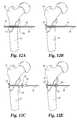
- FIGS. 12illustrates a method of use of a system according to the present invention in anchoring two sections of bone together.
- the delivery system with anchor and attached cableare inserted through the bone.
- the anchoris pivoted.
- a washer and a ferruleare threaded onto the proximal end of the cable, and in FIG. 12D the ferrule is crimped onto the cable, and the cable is cut, leaving the bone fragments anchored as shown in FIG. 12 E.
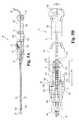
- FIG. 13is a perspective side view of a tensioning, crimping and cutting tool according to the present invention.
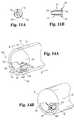
- FIG. 14Ais a perspective view from the distal end of the tensioning, crimping and cutting tool of FIG. 13 .
- FIG. 14Bis a perspective cross-sectional view adjacent the distal end of the tensioning, crimping and cutting tool taken along B-B′ of FIG. 14 A.
- FIG. 15Ais a side cross-sectional view of an alternative cable tensioning mechanism for use with the tool of FIG. 13 .
- FIG. 15Bis a cross-section of the mechanism of FIG. 15A taken along line B—B.
- FIG. 16is a side view of an alternative embodiment of a tensioning, crimping and cutting tool according to the present invention.
- FIG. 17is a partial cross-sectional view of the tool of FIG. 15 .
- FIG. 18is a top view of the tool of FIG. 15 .
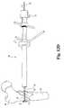
- FIG. 19is a front partial cross-sectional view of still a further embodiment of a tensioning, crimping and cutting tool according to the present invention.
- a tissue anchoring system 10includes a cable 20 having an anchor 30 affixed to a distal end 202 .
- a delivery device 40is also provided for aiding in inserting the cable 20 through of body part including without limitation, bone, cartilage, ligaments, tendons, and muscle:
- cable 20may be any elongated flexible member, the choice of material and size being dependent upon the particular application.
- the flexible memberis referred to and shown as a cable, although it is within the spirit of the invention that a flexible member could similarly be a filament, thread, suture, wire, substantially flat ribbon type member, or any other flexible member suitable for implantation in the body.
- Cable 20may comprise such biocompatible materials as stainless steel, titanium, nitinol, plastic, bioresorbable material, composite material, or cobalt chrome alloy.
- the list of possible cable compositionsis provided for the purpose of illustration and is not intended as limiting, it being understood that selection of a cable may depend on the intended application.
- cable 20is a flexible multistranded metallic cable such as stainless steel as is already known in the art.
- suture material or an equivalent threadlike materialcan be used instead of metallic cable.
- the word “cable”should be taken to mean any flexible material that can be used in surgical applications for affixing two sections of tissue together, and no limitations are intended thereby.
- Anchor 30Attached to the cable's distal end 202 is a generally cylindrical anchor 30 (FIGS. 2A and 2B) that has a closed distal end 302 , an open proximal end 304 , and a partial bore 301 extending from the proximal end 304 but not through to the distal end 302 .
- the distal end 302is rounded to limit damage to surrounding tissue and for ease of insertion through the tissue to be anchored.
- Anchor 30includes a longitudinal axis 303 that extends from the proximal end 304 to the distal end 302 .
- the anchormay be constructed of a material similar to the cable or the anchor may differ from the cable. In one combination, the cable is non-resorbable while the anchor is bioresorbable such that the cable may be removed after a healing period and the anchor may remain in the body.
- the anchor 30has a distal portion 317 heaving a first cross-sectional diameter 306 , or width, larger than the diameter 206 of the cable 20 .
- diameter 306is less than twice diameter 206 , thus providing a relatively small insertion diameter.
- This first cross-sectional diameter 306generally coincides with a cylindrical diameter.
- diameter 306substantially equals the outer diameter of delivery device 40 .
- a second cross-sectional dimension 308is significantly larger than the width 306 . This length 308 generally coincides with the length of the anchor 30 from proximal end 304 to distal end 302 .
- the anchor 30also has a proximal portion 310 opposite the distal portion 317 , the proximal portion 310 having a width 320 , the proximal portion width 320 smaller than the distal portion width 306 .
- the proximal portion 310includes a taper 318 tapering toward the proximal end 304 and a thickness 322 . It will be understood that upon engaging a surface with cable 20 proximally tensioned, taper 318 assists the anchor in flipping to an anchoring position and in sliding under adjacent tissue during the flipping process.
- the anchor 30has a generally longitudinal slot 314 extending from the proximal end 304 into the distal portion 317 .
- Slot 314has a width 312 equal to or greater than the cable diameter 206 .
- the distal end 202 of the cable 20is affixed, for example, via crimping, within the anchor bore 301 between the anchor's distal end 302 and the slot's distal end 315 (see FIG. 1 A).
- a four point crimpis applied to anchor 302 to secure cable 20 within bore 301 .
- cable 20may include a loop at its distal end for attachment through an aperture in the anchor. Any attachment means may be used provided the cable is secured to the anchor with sufficient strength for the intended application.
- the anchor outer diameter 306is less than twice the cable diameter 206 . This permits the cable and anchor combination to be inserted through a relatively small hole or incision. However, the length 308 is much greater than the anchor diameter 306 thereby providing a secure anchorage for the cable.
- the anchor 30is movable in relation to the cable 20 between two positions: a first position (FIG. 1B) wherein the anchor's longitudinal axis 303 is generally parallel to the cable's longitudinal axis 207 and the cable's distal portion 201 resides within anchor slot 314 , and a second position (FIG. 1A) wherein the anchor's longitudinal axis 303 is at an angle to the cable's longitudinal axis 206 and a part of the cable's distal portion 201 extends outside anchor slot 314 .
- Anchor 30includes a curved surface 324 adjacent slot 314 for the cable to bear against and limit abrasion when in the second position. By the nature of the cable-anchor connection, the anchor 30 is biased to the second position.
- biasingoccurs because the first position is unstable. Such biasing may be induced by a pre-set curve in distal portion 201 of cable 20 positioned within slot 314 tending to rotate anchor 30 to the second position. In addition to biasing the anchor towards the second position, taper 318 on the proximal end of anchor 30 urges rotation of the anchor to the second position when it contacts a surface.
- FIGS. 3A and 3Bshow an alternative embodiment of the anchor according to the present invention.
- the anchor 350includes a bead 352 having a bore 360 defined therein.
- the distal end 362 of cable 354is received within the bore and bead 352 is affixed to the cable.
- Pivoting member 356includes a longitudinal slot 370 in communication with a longitudinal bore 364 extending to distal end 358 .
- the bore 364 and slot 370are sized to slidably receive cable 354 therein.
- the distal end 358defines a spherical cavity for receiving a portion of bead 352 .
- Anchor 350is pivotable from the first insertion position shown in FIGS. 3A and 3B to an anchoring position as shown in FIG. 1 A.
- a first embodiment of the delivery device 40(FIGS. 1 and 2) comprises a rigid metallic cylindrical member having a length 405 sufficient to penetrate a desired surgical site and a longitudinal bore 401 extending from a proximal end 404 to a distal end 402 .
- the bore 401is sufficiently large to permit the anchor's proximal portion 310 to fit thereinto but too small to permit the anchor's distal portion 317 to fit thereinto.
- anchor 30could be entirely retained within the delivery device until it is deployed.
- cable 20could be fixed with respect to delivery device 40 to prevent accidental deployment of the anchor.
- the cable/anchor 20 / 30 combinationis inserted into tissue with the aid of the delivery device 40 , which is used to provide mechanical stiffness to the cable 20 .
- the cable's proximal end 204is passed through the delivery device 40 from the distal end 402 through the bore 401 to beyond the proximal end 404 .
- the anchor's proximal portion 310is seated in the delivery device bore 401 adjacent the distal end 402 , and tension is maintained on the cable's proximal end 204 to retain the anchor 30 in the first position.
- proximal end 304may include threads and delivery device 40 may similarly have cooperable threads on the distal end such that the device may be threadedly held on delivery device 40 .
- delivery device 40may similarly have cooperable threads on the distal end such that the device may be threadedly held on delivery device 40 .
- the impelling meanscomprises means for releasably maintaining a longitudinal force on cable 20 in a proximal direction, for retaining the anchor 30 in the first position.
- the delivery device 70comprises a body 72 , which has a handle portion 720 having a proximal end 722 and a recess 728 at the distal end 724 .
- the recess 728which extends from the top 721 to the bottom 723 of the delivery device body 72 , is rounded at its proximal end 725 .
- a longitudinal bore 726extends from the proximal end 722 to the distal 724 end, the bore 726 being dimensioned to permit cable 20 to pass therethrough.
- a pawl housing 75is movably affixed to the delivery device body's distal end 724 via its rounded proximal side 752 , which is dimensioned to slide longitudinally within the delivery device body's recess 728 .
- the pawl housing 75has a pawl cavity 758 that extends from the pawl housing's top 751 through a portion of the pawl housing.
- the pawl housing 75additionally has a longitudinal bore 756 that extends from the proximal side 752 to the distal side 754 through the pawl cavity 758 .
- the bore 756is dimensioned to permit cable 20 to pass therethrough, and is adapted for communication with the delivery device body's bore 726 when the device is assembled for use.
- a spring bore 757extends from the distal side 754 into the pawl cavity 758 and is positioned above the longitudinal bore 756 .
- the delivery device 70further comprises an inner tube 73 that is affixed at its proximal end 732 to the pawl housing's distal side 754 .
- the inner tube 73is generally cylindrical and has a longitudinal bore 736 that extends from the proximal end 732 to the distal end 734 and is dimensioned to permit the cable 20 to pass therethrough but is too small at the distal end 734 to permit the anchor's proximal portion 310 to enter.
- This bore 736is in communication with the pawl housing bore 756 .
- a nose assembly 74that is in mechanical communication with the pawl housing 75 .
- the proximal side 742is affixed to the distal end 724 of the delivery device body 72 with two screws (not shown). These screws are inserted through first and second screw bores 782 that extend from the tapered distal side 744 of the nose assembly 74 through to the proximal side 742 .
- First and second screw bores 782are positioned to meet third and fourth screw bores 727 (FIG. 10B) that extend into the body 72 from the body's distal end 724 .
- the nose assembly 74has a rounded recess 748 that extends from the top 741 to the bottom 743 and is shaped to receive the rounded distal side 754 of the pawl housing 75 .
- the two recesses 748 , 728together define an enclosed elongated hole 79 that has a width 792 dimensioned to closely and slidably engage the pawl housing 75 and a length 794 greater than the length 755 of the pawl housing 75 , permitting the pawl housing 75 to slide longitudinally therein from a first position against the recess proximal end 725 to a second position within the nose assembly recess 748 (dotted line, FIG. 5 B).
- the nose assembly 74further has a longitudinal bore 746 that extends from the proximal side 742 to the distal side 744 , this bore 746 dimensioned and positioned to permit the inner tube 73 to pass therethrough and slide relatively thereto.
- proximal end 762 of a generally cylindrical outer tube 76is Affixed to the nose assembly's distal side 744 .
- Tube 76may be removable affixed to the nose assembly to permit different sizes and configurations of outer tube 76 to be used with delivery device 70 .
- outer tube 76may include two components (not shown) with the distal section removably attached to the proximal section such that alternative configurations and dimensions of the distal section can be attached to accommodate various anchor configurations and cable diameters.
- Bore 766is dimensioned to permit the inner tube 73 to pass therethrough and the anchor proximal portion 310 to slide thereinto.
- bore 766is dimensioned to prevent the anchor's distal portion 317 from passing thereinto. This bore 766 is in communication with the nose assembly bore 746 .
- the outer tube 76preferably has sufficient rigidity to pass through the tissue to be anchored.
- the delivery device 70additionally comprises a pawl 77 that has a longitudinal bore 776 that extends from a proximal side 772 to a distal side 774 and is dimensioned to permit the cable 20 to pass therethrough.
- the pawl 77is dimensioned so that its lower portion fits within the pawl cavity 758 and is pivotally attached adjacent a lower proximal corner 759 thereto, at a position lower than the longitudinal bore 756 .
- the pawl 77is pivotable within the pawl housing cavity 758 between a first position against the pawl housing cavity distal side 761 and a second position against the pawl housing cavity proximal side 763 .
- the pawl longitudinal bore 776is positioned in communication with the pawl housing bore 756 when the pawl 77 is in the first position thereby allowing cable 20 to pass freely therethrough.
- the bore 776is positioned sufficiently off-axis to pinch the cable 20 and thereby prevent a longitudinal movement of the cable 20 .
- placing the pawl 77 in the second positionalso serves to restrain the cable 20 from longitudinal movement.
- the pawl 77also has a spring bore 777 that extends from the distal side 774 in a proximal direction, but does not extend all the way through to the proximal side 772 .
- a pawl spring 78is affixed to the nose assembly's proximal side 742 and extends through the pawl housing spring bore 757 and into the pawl spring bore 777 to bear against the pawl 77 .
- This spring 78thus positioned biases the pawl 77 into the second position, which releasably exerts a longitudinal force on the cable 20 in a proximal direction and by the spring force exerted on pawl 77 biases inner tube 73 to the second position.
- the delivery device member 70 elementsare relatively dimensioned so that a sliding of the inner tube 73 within the outer tube 76 may be accomplished in a longitudinal direction between two positions.
- the inner tube distal end 734In the first position, the inner tube distal end 734 is in spaced relation to the anchor proximal end 304 when the anchor proximal portion 310 is within the outer tube bore 766 .
- the inner tube distal end 734In the second position, the inner tube distal end 734 extends to the outer tube distal end 764 , which pushes the anchor proximal portion 310 out of the outer tube 76 .
- this ejection of the anchor proximal portion 310permits the anchor 30 to flip from its first position to its second position, wherein it can anchor the cable 20 from being pulled in a proximal direction.
- Spring 78biases the pawl housing 75 into the first position.
- Delivery device 800has an outer tube 810 including a series of external threads 836 adjacent the distal end that threadedly engage corresponding internal threads 834 to hold outer tube 810 to nose cone 834 .
- Inner tube 812is slidable within outer tube 810 by a mechanism within housing 814 and controlled between a retracted position with distal end 813 spaced from distal end 811 and an extended position with distal end 813 substantially adjacent distal end 811 .
- inner tube 812abuttingly engages plunger 830 which is biased to a retracted position by spring 832 .
- outer tube 810is sized to receive at least a portion of anchor 30 while inner tube 812 is sized to prevent passage of an anchor such as that shown in FIG. 2 .
- the anchorforces inner tube 812 against plunger 830 .
- the cableextends through aperture 824 in plunger 816 .
- plunger 816is biased into a locked position by spring 822 . In this position the cable is securely held in aperture 824 to prevent movement.
- tension applied to the cablemay be maintained in the locked position. Movement of plunger 816 in the direction of arrow 850 into an unlocked position releases the cable.
- plunger 830Movement of plunger 830 is controlled by plunger 818 through lever 826 . Movement of plunger 818 in the direction of of arrow 860 moves lever 826 about pivot pin 828 to force the lever against plunger 830 to overcome spring 832 and move plunger 830 against inner tube 812 . This movement moves the anchor out of outer tube 810 and permits movement to an anchoring position.
- plunger 816includes a slot (shown in dashed lines) 820 sized to receive a distal portion 819 of plunger 818 . In the locked position, shown in FIG. 6, plunger 816 blocks movement of plunger 818 and thus prevents accidental deployment of the anchor. When plunger 816 is moved in the direction of arrow 850 , slot 820 is aligned with plunger 818 such that distal end 819 may move into slot 820 .
- the present inventionfurther contemplates a crimping tool for attachment of an anchor to a cable, suture or other elongated member.
- a crimping toolfor attachment of an anchor to a cable, suture or other elongated member.
- alternative crimping devicesmay be used to secure anchors to the above described system and that the crimping tool described below may be used or adapted for use with a variety of cabling and suturing systems.
- the crimping tool of the present systemis desirable for the ability to crimp along the axis of a cable at a relatively distant site through a small incision.
- crimping tool 50 of the present inventionprovides several advantages, including a capability of crimping along the longitudinal axis of the cable 20 and of cutting and crimping in one motion. Alternatively, cutting and crimping could be performed separately or by two separate tools with similar function and operation to the single tool shown.
- the crimping tool 50comprises an outer elongated generally cylindrical member 52 having a before 52 l from a proximal end 524 to a distal end 522 .
- a first crimping handle 528is affixed to and extends radially outward from the outer member's proximal end 524 .
- the crimping tool 50additionally comprises an inner elongated generally cylindrical member 54 having a bore 541 dimensioned to permit cable 20 to pass therethrough.
- the inner cylindrical member 54is dimensioned to fit within the outer cylindrical member's bore 521 and to be rotatable relatively thereto about a common longitudinal axis.
- a second crimping handle 548is affixed to and extends radially outward from the inner member's proximal end 544 , which extends proximal of the outer member's proximal end 524 .
- the handles 528 and 548are rotatable between a first, open position wherein the respective distal ends 529 and 549 are spaced apart by approximately 90 degrees to a second, crimping position wherein the distal ends 529 , 549 are generally opposed. Movement of handles 528 and 548 causes inner member 54 and outer member 52 to rotate with respect to each other.
- FIG. 14AThe crimping means of the crimping tool 50 is illustrated in FIG. 14A, which shows the distal end 502 of the tool 50 .
- the distal end 522 of the,outer member 52has a roughly half-moon-shaped solid portion 525 that obscures approximately half of the bore 541 .
- a protrusion 526 positioned in spaced relation to the longitudinal axisextends radially toward the opening leading to the bore 541 .
- the distal end 542 of the inner member 54has a solid portion 545 that obscures the remaining portion of the bore 541 except for a bi-level stepped opening thereinto.
- a first roughly semicircular cutout 552dimensioned, together with the outer member's solid portion 525 , to closely surround a ferrule 94 therein when the handles 528 , 548 are in the open position.
- the outer member's protrusion 526is positioned adjacent the cutout 552 when the handles 528 , 548 are in the open position.
- a second roughly semicircular cutout 554dimensioned to permit the cable 20 to freely slide therethrough but too small to permit the ferrule 94 to pass thereinto.
- the tool 50provides the advantage of crimping the ferrule 94 along the longitudinal axis of the cable 20 , rather than at a right angle thereto, such as is common in the art, which permits the procedure to be accomplished through a small unitary incision without removing surrounding tissue.
- crimping tool of the present inventionis shown for use with cable 20 and ferrule 94 , it is contemplated that the device may be sized for a specific application. Moreover, it is contemplated that inner member 54 and outer member 52 may have removable distal portions. A variety of sizes and configurations of distal portions may be interchangeable to fit a variety of flexible member and crimp configurations and types. It is contemplated that the cabling, crimp and crimping distal portions may be packaged as a unit to ensure proper use by the end user with a standard crimping tool 50 .
- Meansare also provided for applying longitudinal tension in a proximal direction relative to the tissue to be repaired.
- Many devicesare know for providing tension to a cable, however, many require a series of pulleys or other change of direction to accomplish the desired tensioning.
- the inner cylindrical member 54has an externally threaded proximal portion 550 .
- a generally cylindrical tensioner 56has a longitudinal bore 561 therethrough from a proximal end 564 to a distal end 562 that is adapted to be mateable with the inner cylindrical member's threaded proximal portion 550 .
- a handle 565is affixed in radially protruding relation to the tensioner 56 exterior for facilitating a rotation thereof.
- the cable-affixing meanscomprises a cleat 51 positioned adjacent to the tensioner's proximal end 564 .
- the cleat 51which is analogous to such devices known in the art, is adapted to clamp the cable's proximal end 204 to restrain the cable 20 from moving in a longitudinal direction relative to the inner cylindrical member 54 when in a tightened position. When in a releasing position, the cleat 51 permits the cable 20 to slide there past.
- the cable-pulling meanscomprises the tensioner 56 and the inner cylindrical member proximal end 544 , which are relatively movable via a screwing motion therebetween, which serves to change the tension on the cable 20 .
- the inner cylindrical member 54 and tensioner 56are mated, and a cable 20 is inserted through the inner cylindrical member bore 541 and through the tensioner bore 561 , and a proximal portion of the cable is clamped by tightening the cleat 51 . Unscrewing the tensioner 56 relative to the inner cylindrical member 54 serves to pull the cable 20 in a proximal direction, increasing the tension thereon. The nut could be urged to prevent twisting of cable 20 .
- a cutting mechanismis also provided within the tool 50 whereby, when the handles 528 , 548 are moved from the open to the crimping position, the cable 20 is cut at a location proximal to or through the ferrule 94 .
- the cutting mechanismcomprises two jaws 527 , 547 , respectively, affixed within the bores 521 , 541 of the outer cylindrical member 52 and the inner cylindrical member 54 , and are placed into opposition when the arms 528 , 548 are closed, cutting the cable 20 .
- the ferrule 94is typically formed of a metal, such as stainless steel, titanium, or cobalt-chrome alloy.
- the ferrule 94may be made of a resorbable or non-resorbable polymer material.
- the tensioning mechanism shown in FIG. 13may be replaced with the alternative tensioning mechanism of FIG. 15 .
- the alternative tensioning mechanism 590attaches to the distal end 584 of the inner member 54 .
- Outer tube 575is positioned about distal end 584 with spring 577 positioned between the distal end and internal shoulder 585 .
- Inner member 54includes at least one slot 582 adapted to receive a retaining pin 581 to slidably connect the tensioning mechanism 590 .
- Also disposed on the outer surface of distal end 584are a series of grooves 583 or other markings to indicate the position of the outer tube 575 with respect to inner member 54 .
- Inner tube 586includes a cleat 574 pivotally mounted thereon by pivot pin 576 .
- Cleat 574pivots between a clamping position clamping a cable positioned in channel 580 and a non-clamping position, and extends through slot 578 in the outer tube.
- Inner tube 586further includes an externally threaded portion 579 .
- a handle 570 having an internally threaded boreis pivotably mounted on outer tube 575 and is held in place by retaining spring 572 . Rotation of handle 571 urges outer tube 575 against spring 577 , thereby tensioning a cable (not shown) disposed within channel 580 . It will be understood that the tension applied to a cable may be estimated by calibrating the spring force applied as outer tube 575 is adjacent each index marking 583 .
- FIG. 15A further embodiment of a tensioning, crimping and cutting tool according to the present invention is disclosed in FIG. 15 .
- the crimping tool 900includes an outer tube 902 attached to a nose 904 . This nose is attached to a front housing 922 which is interconnected with rear housing 924 .
- inner tube 901is disposed within outer tube 902 and includes a bore 917 for receiving cable 908 .
- the position of cable 908 within inner tube 901is maintained with respect to movement toward the distal end 905 by trigger pawl 906 .
- Trigger pawl 906is pivotally connected to front housing 922 by pivot pin 939 . As shown in FIG.
- Trigger pawl 906biases trigger pawl 906 into the cable retaining position with engaging end 907 engaging cable 908 adjacent the proximal end of inner tube 901 .
- Trigger pawl 906may be moved to a disengaged position by overcoming the force of spring 938 and moving trigger pawl 906 within slot 940 such that engaging end 907 disengages cable 908 .
- Rear housing 924includes a cable tensioner assembly 926 for applying tension to cable 908 towards the proximal end 913 .
- Tensioning assembly 926is operable between a tensioning position and the released position shown in FIG. 16, by movement of handle 910 with respect to handle 912 .
- Handle 910is pivotally attached to rear housing 924 by pivot pin 918 .
- a linking bar 915is joined to handle 910 by pivot pin 916 and interconnects the handle with tensioning assembly 926 through pivot pin 924 . Movement of handle 910 towards handle 912 , fixedly connected to rear housing 924 , causes tensioning assembly 926 to move proximally.
- tensioning assembly 926includes a pair of pawls that grip cable 908 when tensioning assembly 926 is displaced proximally and that allow passage of the cable when tensioning assembly is moving distally.
- Pawl 941is pivotally connected to the tensioning assembly 926 by pivot pin 942 .
- the pawlis urged into a locking position by spring 943 .
- the pawl opposing pawl 941is identical.
- Tensioning assembly 926further includes a set of belleville springs 944 that may be adjusted by movement of threaded shaft 945 to increase or decrease the pressure applied to the cable when the gripping teeth of the pawls are disengaged with the wire as the tensioning assembly is drawn forward.
- Springs 944maintain the position of pin 924 within slot 932 .
- Spring 914disposed between handles 910 and 912 in openings 928 and 930 respectively, urges handle 910 forward. This movement also urges tensioning assembly pawls against front wall 937 which in turn urges the pawls into a disengaged position shown in FIG. 16 .
- tensioning assembly 926is moved to apply proximal tension to cable 908 .
- trigger pawl 906permits proximal movement of the cable. Once proximal tension is released by the tensioning assembly, trigger pawl 906 engages cable 908 to prevent distal movement and thereby maintain the tension while the pawls of the tensioning assembly are disengaged to permit the assembly to return to a forward position. This process may be continued until the desired amount of cable tension has been achieved.
- Cable tensioner, crimper and cutter 900also includes crimping and cutting handles 934 and 936 .
- handle 936is fixedly attached to rear housing 924 while handle 924 is connected by pivot pin 946 to front housing 922 .
- the handlesare biased into a separated position by spring 949 mounted on projection 950 of handle 934 and received within opening 951 in the rear housing.
- Handle 934includes a slot 948 for receiving an inner tube extension 947 (FIG. 16 ). Linear movement of handle 934 toward handle 936 is translated into rotation of inner tube 901 by the engagement of inner tube extension 947 in slot 948 .
- the distal end 905 of inner and outer tubes 901 and 902are configured as shown in FIGS. 14A and 14B such that rotation of the inner tube in relation to the outer tube results in crimping a ferrule and cutting a cable.
- a tensioning, crimping and cutting tool 955includes an inner member 959 , an outer member 958 and a cable retaining assembly 975 .
- Cable retaining assembly 975is preferably received within inner member 959 and includes a cleat 977 pivotally mounted to be moveable between a disengaged position and an engaged position securely holding cable 956 .
- Retaining assembly 975further includes a threaded section 976 .
- Inner member 959includes a flange 972 .
- An internally threaded nut 97 Sis disposed about flange 972 and engages threaded section 976 .
- Nut 973is rotatably maintained in position by mounting pins 974 .
- Inner member 959includes an externally threaded section 971 adjacent flange 972 and at an opposite end, a pair of spaced branches 978 and 979 , each having a flared section 980 and 981 , respectively.
- Branch 978includes a cutting blade 962 and a crimping projection 964 while branch 979 includes a corresponding cutting anvil 963 and crimping depression 965 .
- inner member 959may include more than two branches and may have multiple projections disposed adjacent distal end 967 .
- Inner member 959is disposed within a preferably tubular outer member 958 .
- Outer member 958includes an inclined surface 960 adjacent distal end 966 . Opposite the inclined surfaces is a flange 968 .
- Nut 969is disposed about flange 968 and pivotally retained there by mounting pins 970 .
- cable 956having a distal end anchored in a tissue section (not shown), is threaded through inner member 959 and cable retaining assembly 975 .
- a ferrule 957slidable along cable 956 , is positioned within branches 978 and 979 adjacent crimping projection 964 and crimping depression 965 .
- Cleat 977is rotated to engage cable 956 .
- Nut 973is rotated about external threads 976 to move the cable retaining assembly with respect to the inner member, which bears against a section of tissue (not shown), and thereby applies tension to cable 956 .
- nut 969is rotated with respect to threads 971 to urge outer member 958 downward toward ferrule 957 .
- branches 978 and 979are urged toward each other by acting against inclined surface 960 .
- cutting blade 962 and cutting anvil 963cooperate to cut cable 956 while crimping projection 964 and crimping depression 965 crimp ferrule 957 to securely engage cable 956 .
- nut 973may be engaged by a torque wrench to provide the user with an estimate of the tension applied to cable 956 .
- Variations of the present longitudinal crimping toolare within the spirit of the present invention, such tools utilizing movement preferably occurring within the outer tube such that the opening in the tissue is not significantly enlarged beyond the diameter of the outer tube as a result of the crimping process.
- FIGS. 9 and 10An alternate form of a tissue anchor comprises an eyelet anchor 32 , the structure and function of which are illustrated in FIGS. 9 and 10.
- the eyelet anchor 32is affixed at a proximal end 324 to the cable distal end 202 , and the eyelet anchor 32 has an eyelet hole 321 at a distal end 322 for receiving an anchoring screw 79 .
- the eyelet anchor 32also has a cable bore 323 adjacent the proximal end 324 adapted to permit cable 20 to pass therethrough and to be crimped therein.
- the eyelet anchor 32has a central portion 325 that is dimensioned larger than the distal portion of the delivery device member cylindrical portion bore 401 or 766 .
- the eyelet anchor 32further has a proximal portion 326 that is dimensioned to reside within the distal portion of the delivery device member cylindrical portion bore 401 or 766 .
- the eyelet anchor proximal portion 326is retainable within the bore 401 or 766 when the cable 20 to which it is attached is under longitudinal tension in a proximal direction.
- eyelet anchor 32is formed of a deformable material which tends to resume its original shape. It will be understood that an eyelet anchor 32 formed of such a material may be deformed to be received within outer tube 76 , such that inner,tube 73 will force eyelet anchor 32 out of outer tube 76 . The anchor may then resume its larger original dimensions.
- Opening protector 150includes a surface engaging portion 152 adapted to engage the exterior surface of the bone adjacent the opening to prevent advancement into the bone.
- Opening protector 150also includes a cylindrical portion 151 that extends into the bone opening and provides a lumen for passage of cable 20 .
- the exterior surface of the cylindrical portion 151includes a roughened surface to engage the surrounding bone to prevent dislogdement. While it is contemplated that the roughened surface may be threads such that the protector may be screwed into the opening, preferably, the surface includes a series of circular projections 153 having an inclined leading edge for ease of insertion and a cavity adjacent the trailing edge to inhibit removal. Also, it is contemplated that cylindrical portion 151 could be substantially eliminated and anchoring elements could extend through, or be a part of, surface engaging portion 152 .
- the surface engaging position 152lie substantially flush with the surface of the bone.
- cylindrical portion 151 and surface engaging portion 152will be perpendicular.
- the corner 154 between the cylindrical portion 151 and surface engagement portion 152is rounded. This is intended to limit the abrasion and wear on the anchoring member as it slides across the corner.
- the protectoris particularly useful in applications were the cable or suture will be pulled against the corner of the bone opening.
- eyelet anchor 32 secured by bone screw 79 and cable 20extends through opening protector 150 .
- Tensionis applied to cable 20 and is t maintained by crimped ferrule 94 bearing against washer 14 . Without opening protector 150 , cable 20 would have a tendency to cut through the edge of the bone opening causing damage to surrounding tissue and reducing the tension on cable 20 .
- the method for utilizing the above-described systemcomprises the following steps, as shown in FIGS. 12A-E, for anchoring two sections of bone together. It is obvious to one skilled in the art that the same technique is applicable to a method for anchoring two different bones together, for anchoring other types of tissue together, or for anchoring another type of tissue to bone [see, e.g., FIG. 8, illustrating the anchoring of a ligament 92 (here, a medial collateral ligament) to a bone 90 (here, the tibia)]. Therefore, no limitations are intended by the presentation of this exemplary embodiment.
- Two holes 115 and 116are drilled through the bone sections 90 and 91 , the cable/anchor/delivery device 20 / 30 / 40 combination is inserted through the holes 115 , 116 until the anchor 30 is completely through the distal hole 115 (FIG. 12 A).
- anchor 30may include a sharp tip such that the anchor may be pushed through unprepared bone or other tissue. The cable tension is released, which permits the anchor 30 to rotate and be restrained on the distal side of the distal hole 115 (FIG. 12 B).
- the insertion devicecould also be used with an anchor designed to be embedded within the bone, i.e. the anchor would not exit the distal cortical bone and instead would be deployed in the cancellous bone.
- the delivery device 30is removed from the cable 20 , and a washer 93 and ferrule 94 are threaded onto the cable to a position adjacent the proximal hole 912 (FIG. 12 C).
- the cable 20is then inserted into the crimping tool 50 sufficiently far that the ferrule 94 is positioned within the first cutout 552 adjacent the second cutout 554 .
- the cable 20is clamped with the cleat 51 and pulled to a desired tension (FIG. 12 D).
- Tensioner 56may be unscrewed with respect to inner cylindrical member 54 while cleat 51 securely holds cable 20 , thereby pulling the bone fragments together and applying measurable compression between the fragments.
- the crimping tool 50is closed to crimp the ferrule 94 onto the cable 20 and also to cut the cable 20 (FIG. 12 E).
- the crimpmay be made first, and then a separate cable cutting tool (not shown) can be used for thicker types of cable.
- an eyelet anchor 60such as shown in FIG. 9, may also be used.
- the eyelet anchor 60is threaded onto the cable 20 via cable bore 602 , which is at the proximal end 601 , before the ferrule 94 is threaded on, and, after the crimp is made, a screw 61 is inserted through the screw hole 604 , which forms the eyelet, and into the bone 90 to attach the eyelet anchor 60 (FIG. 9 ).
- the method described abovemay be performed utilizing any combination of the delivery devices and tensioning, crimping and cutting tools described herein.
- a suture material anchor system 83as shown in FIG. 7A for repairing soft tissue, comprises a suture anchor 84 for use with a delivery device, such as either of the delivery devices 40 , 70 or 800 as described above.
- the suture anchor 84is an elongated member having a longitudinal axis extending from a proximal end 844 to a distal end 842 .
- the suture anchor 84also has a pair 845 , 846 of cross-bores extending from a first side 847 through to a second, opposed side 848 .
- Cross-bores 845 , 846are dimensioned to permit suture material 86 to pass therethrough. In use suture material 86 is threaded through bore 845 from the first side 847 to the second side 848 .and then through the other bore 846 from the second side 848 to the first side 847 .
- the suture anchor 84has a narrowed proximal portion 843 at the proximal end 844 , proximal of the cross-bores 845 , 846 , that is dimensioned to be insertable into and supported by the impeller bore 401 or the outer tube bore 766 , as previously described for the pivotable anchor 30 .
- the central portion 848is dimensioned too large to be insertable into the impeller bore 401 or the outer tube bore 766 .
- the suture anchor 84has a first cross-sectional dimension generally along the longitudinal axis greater than a second cross-sectional dimension generally perpendicular to the longitudinal axis, as before for the pivotable anchor 30 .
- the suture anchor 84is manipulable and pivotable by pulling the ends of the suture material, which can accomplish a bracing of the suture anchor 84 against the distal side of the tissue 85 to be repaired.
- the ends of the suture material 86are retainable outside the incision, or, alternatively, one end 862 can be retained outside the introducing incision 88 , and a second end 864 can be pulled through a second incision 89 , as shown in FIG. 7 B.
- a method of using the system 83 to repair a soft tissue tear such as a meniscal tear Tcomprises the steps of piercing the tissue 85 across the tear T, inserting the delivery device/suture material/anchor system into the pierced hole 834 , manipulating the delivery device so that the anchor 84 emerges from the far end of the tear T and rotates so that the anchor 84 has its length generally perpendicular to the tear-T and thus will not slip out. The surgeon can then manipulate the suture material 86 and tie it off as desired to secure the repair. Alternatively, a second incision 835 may be made at an adjacent site across the tear T, as shown in FIG. 7B, and the two pieces of suture material then joined together to strengthen the repair.
- the anchor 84can either be inserted into the body of the tissue 84 , as shown in FIG. 7B, or it can be impelled completely through the tissue (not shown), depending upon the application, to anchor the suture material 86 .
Landscapes
- Health & Medical Sciences (AREA)
- Orthopedic Medicine & Surgery (AREA)
- Life Sciences & Earth Sciences (AREA)
- Surgery (AREA)
- Heart & Thoracic Surgery (AREA)
- Engineering & Computer Science (AREA)
- Biomedical Technology (AREA)
- Veterinary Medicine (AREA)
- Animal Behavior & Ethology (AREA)
- General Health & Medical Sciences (AREA)
- Public Health (AREA)
- Medical Informatics (AREA)
- Nuclear Medicine, Radiotherapy & Molecular Imaging (AREA)
- Molecular Biology (AREA)
- Rheumatology (AREA)
- Oral & Maxillofacial Surgery (AREA)
- Neurology (AREA)
- Vascular Medicine (AREA)
- Transplantation (AREA)
- Cardiology (AREA)
- Rehabilitation Therapy (AREA)
- Surgical Instruments (AREA)
Abstract
Description
Claims (25)
Priority Applications (3)
| Application Number | Priority Date | Filing Date | Title |
|---|---|---|---|
| US09/560,293US6544267B1 (en) | 1998-01-26 | 2000-04-27 | Tissue anchoring system and method |
| US10/068,115US6761722B2 (en) | 1998-01-26 | 2002-02-05 | Tissue anchoring system and method |
| US10/888,938US20050033366A1 (en) | 1998-01-26 | 2004-07-09 | Tissue anchoring system and method |
Applications Claiming Priority (2)
| Application Number | Priority Date | Filing Date | Title |
|---|---|---|---|
| US09/013,434US6068648A (en) | 1998-01-26 | 1998-01-26 | Tissue anchoring system and method |
| US09/560,293US6544267B1 (en) | 1998-01-26 | 2000-04-27 | Tissue anchoring system and method |
Related Parent Applications (1)
| Application Number | Title | Priority Date | Filing Date |
|---|---|---|---|
| US09/013,434DivisionUS6068648A (en) | 1998-01-26 | 1998-01-26 | Tissue anchoring system and method |
Related Child Applications (1)
| Application Number | Title | Priority Date | Filing Date |
|---|---|---|---|
| US10/068,115DivisionUS6761722B2 (en) | 1998-01-26 | 2002-02-05 | Tissue anchoring system and method |
Publications (1)
| Publication Number | Publication Date |
|---|---|
| US6544267B1true US6544267B1 (en) | 2003-04-08 |
Family
ID=21759950
Family Applications (4)
| Application Number | Title | Priority Date | Filing Date |
|---|---|---|---|
| US09/013,434Expired - LifetimeUS6068648A (en) | 1998-01-26 | 1998-01-26 | Tissue anchoring system and method |
| US09/560,293Expired - LifetimeUS6544267B1 (en) | 1998-01-26 | 2000-04-27 | Tissue anchoring system and method |
| US10/068,115Expired - LifetimeUS6761722B2 (en) | 1998-01-26 | 2002-02-05 | Tissue anchoring system and method |
| US10/888,938AbandonedUS20050033366A1 (en) | 1998-01-26 | 2004-07-09 | Tissue anchoring system and method |
Family Applications Before (1)
| Application Number | Title | Priority Date | Filing Date |
|---|---|---|---|
| US09/013,434Expired - LifetimeUS6068648A (en) | 1998-01-26 | 1998-01-26 | Tissue anchoring system and method |
Family Applications After (2)
| Application Number | Title | Priority Date | Filing Date |
|---|---|---|---|
| US10/068,115Expired - LifetimeUS6761722B2 (en) | 1998-01-26 | 2002-02-05 | Tissue anchoring system and method |
| US10/888,938AbandonedUS20050033366A1 (en) | 1998-01-26 | 2004-07-09 | Tissue anchoring system and method |
Country Status (6)
| Country | Link |
|---|---|
| US (4) | US6068648A (en) |
| EP (1) | EP1051114B1 (en) |
| JP (1) | JP4065371B2 (en) |
| KR (1) | KR20010040394A (en) |
| AU (1) | AU2461799A (en) |
| WO (1) | WO1999037219A1 (en) |
Cited By (75)
| Publication number | Priority date | Publication date | Assignee | Title |
|---|---|---|---|---|
| US20020177853A1 (en)* | 2001-05-23 | 2002-11-28 | Alan Chervitz | Apparatus and method for orthopedic fixation |
| US20040199169A1 (en)* | 2002-11-20 | 2004-10-07 | Koons Kirk C. | Cable clamp tool for surgical applications |
| US20050015153A1 (en)* | 2002-05-24 | 2005-01-20 | Medicine Lodge, Inc. | Implants and related methods and apparatus for securing an implant on an articulating surface of an orthopedic joint |
| US20050143745A1 (en)* | 2003-12-30 | 2005-06-30 | Medicinelodge, Inc. | Instruments and methods for preparing a joint articulation surface for an implant |
| US20050143831A1 (en)* | 2003-12-30 | 2005-06-30 | Medicinelodge, Inc. | Tibial condylar hemiplasty implants, anchor assemblies, and related methods |
| US20050143731A1 (en)* | 2003-12-30 | 2005-06-30 | Medicinelodge, Inc. | Tibial condylar hemiplasty tissue preparation instruments and methods |
| US20050149044A1 (en)* | 2003-12-30 | 2005-07-07 | Medicinelodge, Inc. | Methods and apparatus for forming a tunnel through a proximal end of a tibia |
| US20050149086A1 (en)* | 2003-11-20 | 2005-07-07 | Osseus, Llc | Method and device for cutting surgical wire or cable |
| US20050240191A1 (en)* | 2004-04-21 | 2005-10-27 | Thomas Albertson | Sternal reconstruction system |
| US20050240198A1 (en)* | 2004-04-21 | 2005-10-27 | Thomas Albertson | Sternal reconstruction system |
| US20060009854A1 (en)* | 2004-07-09 | 2006-01-12 | Medicinelodge, Inc. | Guide templates for surgical implants and related methods |
| US20060106423A1 (en)* | 2004-09-28 | 2006-05-18 | Thomas Weisel | Suture anchor |
| US20060190041A1 (en)* | 2003-06-11 | 2006-08-24 | Medicinelodge, Inc. | Compact line locks and methods |
| US20060229623A1 (en)* | 2004-10-26 | 2006-10-12 | Bonutti Peter M | Tissue fixation system and method |
| US20060276896A1 (en)* | 2005-06-02 | 2006-12-07 | Medicinelodge, Inc. | Bone implants with integrated line locks |
| US20070100351A1 (en)* | 2005-10-31 | 2007-05-03 | Deffenbaugh Daren L | Multiple suture anchor delivery device, suture anchor delivery kit and associated method |
| US20070100350A1 (en)* | 2005-10-31 | 2007-05-03 | Deffenbaugh Daren L | Suture anchor cartridge holder, suture anchor cartridge and associated method |
| US20070100352A1 (en)* | 2005-10-31 | 2007-05-03 | Deffenbaugh Daren L | Cartridge suture anchor delivery device, suture anchor delivery device and associated method |
| US20070156174A1 (en)* | 2006-01-03 | 2007-07-05 | Arthrotek, Inc. | Method and apparatus for repairing a meniscus |
| US20070270833A1 (en)* | 2006-02-07 | 2007-11-22 | Bonutti Peter M | Methods and devices for trauma welding |
| US20080077154A1 (en)* | 2006-09-21 | 2008-03-27 | Edwards Scott G | System and method of bone compression and fixation |
| US20080300607A1 (en)* | 2005-12-28 | 2008-12-04 | C.R. Bard, Inc. | Apparatus and Method for Introducing Implants |
| US7488347B1 (en) | 2005-01-06 | 2009-02-10 | Medicine Lodge, Inc. | Transosseous graft retention system and method |
| US20090062847A1 (en)* | 2007-08-31 | 2009-03-05 | Ken Christopher G M | Closure medical device |
| US7641694B1 (en) | 2005-01-06 | 2010-01-05 | IMDS, Inc. | Line lock graft retention system and method |
| US20100305585A1 (en)* | 2003-06-11 | 2010-12-02 | Medicinelodge, Inc. Dba Imds Co-Innovation | Line lock threading systems and methods |
| US20110238147A1 (en)* | 2009-09-22 | 2011-09-29 | Penumbra, Inc. | Manual actuation system for deployment of implant |
| US8206280B2 (en) | 2007-11-13 | 2012-06-26 | C. R. Bard, Inc. | Adjustable tissue support member |
| US8257394B2 (en) | 2004-05-07 | 2012-09-04 | Usgi Medical, Inc. | Apparatus and methods for positioning and securing anchors |
| US8287538B2 (en) | 2008-01-14 | 2012-10-16 | Conventus Orthopaedics, Inc. | Apparatus and methods for fracture repair |
| US8460319B2 (en) | 2010-01-11 | 2013-06-11 | Anulex Technologies, Inc. | Intervertebral disc annulus repair system and method |
| US8480559B2 (en) | 2006-09-13 | 2013-07-09 | C. R. Bard, Inc. | Urethral support system |
| US8496657B2 (en) | 2006-02-07 | 2013-07-30 | P Tech, Llc. | Methods for utilizing vibratory energy to weld, stake and/or remove implants |
| US8617185B2 (en)* | 2007-02-13 | 2013-12-31 | P Tech, Llc. | Fixation device |
| US8747439B2 (en) | 2000-03-13 | 2014-06-10 | P Tech, Llc | Method of using ultrasonic vibration to secure body tissue with fastening element |
| US20140172095A1 (en)* | 2009-07-09 | 2014-06-19 | Smith & Nephew, Inc. | Tissue graft anchor assembly and instrumentation for use therewith |
| US8808329B2 (en) | 1998-02-06 | 2014-08-19 | Bonutti Skeletal Innovations Llc | Apparatus and method for securing a portion of a body |
| US8814902B2 (en) | 2000-05-03 | 2014-08-26 | Bonutti Skeletal Innovations Llc | Method of securing body tissue |
| US8845512B2 (en) | 2005-11-14 | 2014-09-30 | C. R. Bard, Inc. | Sling anchor system |
| US8845699B2 (en) | 1999-08-09 | 2014-09-30 | Bonutti Skeletal Innovations Llc | Method of securing tissue |
| US8870916B2 (en) | 2006-07-07 | 2014-10-28 | USGI Medical, Inc | Low profile tissue anchors, tissue anchor systems, and methods for their delivery and use |
| US8906022B2 (en) | 2010-03-08 | 2014-12-09 | Conventus Orthopaedics, Inc. | Apparatus and methods for securing a bone implant |
| US8961518B2 (en) | 2010-01-20 | 2015-02-24 | Conventus Orthopaedics, Inc. | Apparatus and methods for bone access and cavity preparation |
| US9011501B2 (en) | 2011-12-14 | 2015-04-21 | DePuy Synthes Products, Inc. | Device for compression across fractures |
| US9060767B2 (en) | 2003-04-30 | 2015-06-23 | P Tech, Llc | Tissue fastener and methods for using same |
| US9089323B2 (en) | 2005-02-22 | 2015-07-28 | P Tech, Llc | Device and method for securing body tissue |
| US9138222B2 (en) | 2000-03-13 | 2015-09-22 | P Tech, Llc | Method and device for securing body tissue |
| US9149281B2 (en) | 2002-03-20 | 2015-10-06 | P Tech, Llc | Robotic system for engaging a fastener with body tissue |
| US9226828B2 (en) | 2004-10-26 | 2016-01-05 | P Tech, Llc | Devices and methods for stabilizing tissue and implants |
| US9271766B2 (en) | 2004-10-26 | 2016-03-01 | P Tech, Llc | Devices and methods for stabilizing tissue and implants |
| US9439642B2 (en) | 2006-02-07 | 2016-09-13 | P Tech, Llc | Methods and devices for utilizing bondable materials |
| US9463012B2 (en) | 2004-10-26 | 2016-10-11 | P Tech, Llc | Apparatus for guiding and positioning an implant |
| US9730739B2 (en) | 2010-01-15 | 2017-08-15 | Conventus Orthopaedics, Inc. | Rotary-rigid orthopaedic rod |
| US9737294B2 (en) | 2013-01-28 | 2017-08-22 | Cartiva, Inc. | Method and system for orthopedic repair |
| US9750496B2 (en) | 2002-08-27 | 2017-09-05 | P Tech, Llc | System for securing a portion of a body |
| US9770238B2 (en) | 2001-12-03 | 2017-09-26 | P Tech, Llc | Magnetic positioning apparatus |
| US9788862B2 (en) | 2014-05-12 | 2017-10-17 | DePuy Synthes Products, Inc. | Sacral fixation system |
| US9888916B2 (en) | 2004-03-09 | 2018-02-13 | P Tech, Llc | Method and device for securing body tissue |
| US9956021B1 (en) | 2017-01-03 | 2018-05-01 | DePuy Synthes Products, Inc. | Tensioning and crimping tool for orthopedic cable tensioning |
| WO2018106443A2 (en) | 2016-12-09 | 2018-06-14 | DePuy Synthes Products, Inc. | Cutting tool |
| US10022132B2 (en) | 2013-12-12 | 2018-07-17 | Conventus Orthopaedics, Inc. | Tissue displacement tools and methods |
| US10058393B2 (en) | 2015-10-21 | 2018-08-28 | P Tech, Llc | Systems and methods for navigation and visualization |
| US10064670B2 (en) | 2014-05-12 | 2018-09-04 | DePuy Synthes Products, Inc. | Sacral fixation system |
| US10076377B2 (en) | 2013-01-05 | 2018-09-18 | P Tech, Llc | Fixation systems and methods |
| US10179012B2 (en) | 2013-01-28 | 2019-01-15 | Cartiva, Inc. | Systems and methods for orthopedic repair |
| US10238444B2 (en) | 2016-05-10 | 2019-03-26 | DePuy Synthes Products, Inc. | Insertion tool for flip anchor cable system insertion |
| US10499972B2 (en) | 2017-01-03 | 2019-12-10 | DePuy Synthes Products, Inc. | Mini cable tensioner for orthopedic cable tensioning |
| US10675015B2 (en) | 2017-07-12 | 2020-06-09 | Ethicon, Inc. | Systems, devices and methods for delivering transfascial suture implants for securing surgical mesh to tissue |
| US10918426B2 (en) | 2017-07-04 | 2021-02-16 | Conventus Orthopaedics, Inc. | Apparatus and methods for treatment of a bone |
| US11246638B2 (en) | 2006-05-03 | 2022-02-15 | P Tech, Llc | Methods and devices for utilizing bondable materials |
| US11253296B2 (en) | 2006-02-07 | 2022-02-22 | P Tech, Llc | Methods and devices for intracorporeal bonding of implants with thermal energy |
| US11278331B2 (en) | 2006-02-07 | 2022-03-22 | P Tech Llc | Method and devices for intracorporeal bonding of implants with thermal energy |
| US11395687B2 (en) | 2019-03-01 | 2022-07-26 | DePuy Synthes Products, Inc. | Insertion tool for flip anchor cable system insertion |
| US11395688B2 (en) | 2019-09-30 | 2022-07-26 | DePuy Synthes Products, Inc. | Tool for crimping orthopedic cable |
| US11596419B2 (en) | 2017-03-09 | 2023-03-07 | Flower Orthopedics Corporation | Plating depth gauge and countersink instrument |
Families Citing this family (429)
| Publication number | Priority date | Publication date | Assignee | Title |
|---|---|---|---|---|
| US5718717A (en) | 1996-08-19 | 1998-02-17 | Bonutti; Peter M. | Suture anchor |
| US5766183A (en) | 1996-10-21 | 1998-06-16 | Lasersurge, Inc. | Vascular hole closure |
| US5893850A (en) | 1996-11-12 | 1999-04-13 | Cachia; Victor V. | Bone fixation device |
| US6648890B2 (en) | 1996-11-12 | 2003-11-18 | Triage Medical, Inc. | Bone fixation system with radially extendable anchor |
| US6632224B2 (en)* | 1996-11-12 | 2003-10-14 | Triage Medical, Inc. | Bone fixation system |
| US20050143734A1 (en)* | 1996-11-12 | 2005-06-30 | Cachia Victor V. | Bone fixation system with radially extendable anchor |
| US6102934A (en)* | 1998-06-02 | 2000-08-15 | Li; Lehmann K. | Anchor tool and method and apparatus for emplacing anchor in a borehole |
| US6368326B1 (en)* | 1998-09-28 | 2002-04-09 | Daos Limited | Internal cord fixation device |
| US7410489B2 (en)* | 1998-09-28 | 2008-08-12 | Daos Limited | Internal cord fixation device |
| US6045572A (en)* | 1998-10-16 | 2000-04-04 | Cardiac Assist Technologies, Inc. | System, method and apparatus for sternal closure |
| GB2346408B (en)* | 1999-02-08 | 2001-01-03 | Latchways Plc | Safety line anchor |
| US6660022B1 (en)* | 1999-06-01 | 2003-12-09 | Smith & Nephew, Inc. | Rotor blade anchor and tool for installing same |
| US6626899B2 (en) | 1999-06-25 | 2003-09-30 | Nidus Medical, Llc | Apparatus and methods for treating tissue |
| US6991643B2 (en) | 2000-12-20 | 2006-01-31 | Usgi Medical Inc. | Multi-barbed device for retaining tissue in apposition and methods of use |
| US20040122456A1 (en)* | 2002-12-11 | 2004-06-24 | Saadat Vahid C. | Methods and apparatus for gastric reduction |
| ATE329531T1 (en) | 1999-07-02 | 2006-07-15 | Quickpass Inc | SURGICAL SEWING DEVICE |
| US6534008B1 (en) | 1999-07-08 | 2003-03-18 | Lee Angros | In situ heat induced antigen recovery and staining apparatus and method |
| US6596014B2 (en)* | 1999-07-13 | 2003-07-22 | Scion Cardio-Vascular, Inc. | Suture with toggle and method of manufacture therefor |
| US8128698B2 (en) | 1999-10-20 | 2012-03-06 | Anulex Technologies, Inc. | Method and apparatus for the treatment of the intervertebral disc annulus |
| US6524317B1 (en) | 1999-12-30 | 2003-02-25 | Opus Medical, Inc. | Method and apparatus for attaching connective tissues to bone using a knotless suture anchoring device |
| AU7862200A (en) | 2000-01-03 | 2001-07-16 | Y. Freedland | Flip-wing tissue retainer |
| US8932330B2 (en)* | 2000-03-13 | 2015-01-13 | P Tech, Llc | Method and device for securing body tissue |
| US7963966B2 (en) | 2000-06-06 | 2011-06-21 | Cole J Dean | Bone fixation system and method of use |
| EP1299041B1 (en)* | 2000-06-12 | 2006-10-04 | Jeffrey E. Yeung | Intervertebral disc repair |
| DE20122783U1 (en)* | 2000-06-17 | 2007-11-15 | Leica Microsystems Cms Gmbh | Arrangement for examining microscopic specimens with a scanning microscope and illumination device for a scanning microscope |
| US6325804B1 (en)* | 2000-06-28 | 2001-12-04 | Ethicon, Inc. | Method for fixing a graft in a bone tunnel |
| US6451030B2 (en) | 2000-06-30 | 2002-09-17 | Li Medical Technologies, Inc. | Rotor blade anchor and tool for installing same particularlly for arthroscopic installation |
| US6638312B2 (en) | 2000-08-04 | 2003-10-28 | Depuy Orthopaedics, Inc. | Reinforced small intestinal submucosa (SIS) |
| US8366787B2 (en) | 2000-08-04 | 2013-02-05 | Depuy Products, Inc. | Hybrid biologic-synthetic bioabsorbable scaffolds |
| WO2002015795A2 (en)* | 2000-08-25 | 2002-02-28 | Sutura, Inc. | Suture cutter |
| US6652561B1 (en) | 2000-10-13 | 2003-11-25 | Opus Medical, Inc | Method and apparatus for attaching connective tissues to bone using a perforated suture anchoring device |
| US6635059B2 (en)* | 2001-01-03 | 2003-10-21 | Bernard L. Randall | Cannulated locking screw system especially for transiliac implant |
| US8313496B2 (en)* | 2001-02-02 | 2012-11-20 | Lsi Solutions, Inc. | System for endoscopic suturing |
| US6770076B2 (en) | 2001-02-12 | 2004-08-03 | Opus Medical, Inc. | Method and apparatus for attaching connective tissues to bone using a knotless suture anchoring device |
| WO2006130693A2 (en) | 2005-06-01 | 2006-12-07 | Arthrocare Corporation | Knotless suture anchoring device having deforming section to accommodate sutures of various diameters |
| US7686807B2 (en)* | 2001-03-22 | 2010-03-30 | Interventional Spine, Inc. | Tool for bone fixation device |
| US6511481B2 (en) | 2001-03-30 | 2003-01-28 | Triage Medical, Inc. | Method and apparatus for fixation of proximal femoral fractures |
| US6887243B2 (en) | 2001-03-30 | 2005-05-03 | Triage Medical, Inc. | Method and apparatus for bone fixation with secondary compression |
| US6619291B2 (en)* | 2001-04-24 | 2003-09-16 | Edwin J. Hlavka | Method and apparatus for catheter-based annuloplasty |
| US8202315B2 (en) | 2001-04-24 | 2012-06-19 | Mitralign, Inc. | Catheter-based annuloplasty using ventricularly positioned catheter |
| US20060069429A1 (en)* | 2001-04-24 | 2006-03-30 | Spence Paul A | Tissue fastening systems and methods utilizing magnetic guidance |
| US6547800B2 (en) | 2001-06-06 | 2003-04-15 | Opus Medical, Inc. | Method and apparatus for attaching connective tissues to bone using a cortical bone anchoring device |
| US20050027307A1 (en)* | 2001-07-16 | 2005-02-03 | Schwartz Herbert Eugene | Unitary surgical device and method |
| US8012205B2 (en) | 2001-07-16 | 2011-09-06 | Depuy Products, Inc. | Cartilage repair and regeneration device |
| AU2002316694B2 (en)* | 2001-07-16 | 2007-09-06 | Depuy Products, Inc. | Hybrid biologic/synthetic porous extracellular matrix scaffolds |
| US7819918B2 (en) | 2001-07-16 | 2010-10-26 | Depuy Products, Inc. | Implantable tissue repair device |
| WO2003007784A2 (en) | 2001-07-16 | 2003-01-30 | Depuy Products, Inc. | Meniscus regeneration device and method |
| JP4197158B2 (en) | 2001-07-16 | 2008-12-17 | デピュイ・プロダクツ・インコーポレイテッド | Devices with naturally occurring biologically derived materials |
| US8025896B2 (en) | 2001-07-16 | 2011-09-27 | Depuy Products, Inc. | Porous extracellular matrix scaffold and method |
| WO2003007786A2 (en)* | 2001-07-16 | 2003-01-30 | Depuy Products, Inc. | Porous delivery scaffold and method |
| AU2002313694B2 (en)* | 2001-07-16 | 2007-08-30 | Depuy Products, Inc. | Cartilage repair apparatus and method |
| US20030078601A1 (en)* | 2001-10-22 | 2003-04-24 | Oleg Shikhman | Crimping and cutting device |
| DE60239559D1 (en)* | 2001-10-22 | 2011-05-05 | Interventional Therapies Llc | WUNDNÄHVORRICHTUNG |
| US6685706B2 (en) | 2001-11-19 | 2004-02-03 | Triage Medical, Inc. | Proximal anchors for bone fixation system |
| US6780198B1 (en) | 2001-12-06 | 2004-08-24 | Opus Medical, Inc. | Bone anchor insertion device |
| US6855157B2 (en) | 2002-02-04 | 2005-02-15 | Arthrocare Corporation | Method and apparatus for attaching connective tissues to bone using a knotless suture anchoring device |
| CA2477220C (en) | 2002-03-14 | 2007-11-06 | Jeffrey E. Yeung | Suture anchor and approximating device |
| GB0208667D0 (en)* | 2002-04-16 | 2002-05-29 | Atlantech Medical Devices Ltd | A transverse suspension device |
| US7326222B2 (en)* | 2002-05-01 | 2008-02-05 | Arthrex, Inc. | Suture tensioning device |
| US6793678B2 (en) | 2002-06-27 | 2004-09-21 | Depuy Acromed, Inc. | Prosthetic intervertebral motion disc having dampening |
| US20040166169A1 (en)* | 2002-07-15 | 2004-08-26 | Prasanna Malaviya | Porous extracellular matrix scaffold and method |
| JP4988203B2 (en) | 2002-07-19 | 2012-08-01 | インターヴェンショナル スパイン、インコーポレイテッド | Spinal fixation method and spinal fixation device |
| CN100421628C (en)* | 2002-09-24 | 2008-10-01 | 伊西康内外科公司 | Ultrasonic surgical instrument with increased working length |
| EP1555949A4 (en)* | 2002-10-21 | 2009-07-01 | Mitralign Inc | Method and apparatus for performing catheter-based annuloplasty using local plications |
| US20050119735A1 (en) | 2002-10-21 | 2005-06-02 | Spence Paul A. | Tissue fastening systems and methods utilizing magnetic guidance |
| US7070601B2 (en) | 2003-01-16 | 2006-07-04 | Triage Medical, Inc. | Locking plate for bone anchors |
| JP2006519087A (en)* | 2003-02-28 | 2006-08-24 | トリアージ メディカル、 インコーポレイテッド | Tools for bone fixation devices |
| US7833225B2 (en)* | 2003-04-24 | 2010-11-16 | Orthohelix Surgical Designs, Inc. | Method and device for bone stabilization using a threaded compression wire |
| WO2004098453A2 (en) | 2003-05-06 | 2004-11-18 | Triage Medical, Inc. | Proximal anchors for bone fixation system |
| JP4166632B2 (en)* | 2003-06-06 | 2008-10-15 | オリンパス株式会社 | Suture device |
| US7341558B2 (en)* | 2003-09-19 | 2008-03-11 | Medcanica, Llc | Pericardial retractor |
| US7896917B2 (en)* | 2003-10-15 | 2011-03-01 | Biomet Sports Medicine, Llc | Method and apparatus for graft fixation |
| US7682374B2 (en) | 2003-10-21 | 2010-03-23 | Arthrocare Corporation | Knotless suture lock and bone anchor implant method |
| US7166127B2 (en) | 2003-12-23 | 2007-01-23 | Mitralign, Inc. | Tissue fastening systems and methods utilizing magnetic guidance |
| US8864822B2 (en) | 2003-12-23 | 2014-10-21 | Mitralign, Inc. | Devices and methods for introducing elements into tissue |
| US7901404B2 (en) | 2004-01-16 | 2011-03-08 | Arthrocare Corporation | Bone harvesting device and method |
| ATE361724T1 (en)* | 2004-01-23 | 2007-06-15 | Depuy Orthopaedics Inc | SET OF BONE PROTECTION EQUIPMENT |
| WO2005077279A1 (en)* | 2004-02-09 | 2005-08-25 | Eclectic Grey Mater Designs, Llc | Safety suture needle assemblies and methods |
| US7608092B1 (en) | 2004-02-20 | 2009-10-27 | Biomet Sports Medicince, LLC | Method and apparatus for performing meniscus repair |
| US7976539B2 (en) | 2004-03-05 | 2011-07-12 | Hansen Medical, Inc. | System and method for denaturing and fixing collagenous tissue |
| CA2562061C (en)* | 2004-04-26 | 2011-06-21 | Bioduct Llc | Stent for avascular meniscal repair and regeneration |
| US7569233B2 (en)* | 2004-05-04 | 2009-08-04 | Depuy Products, Inc. | Hybrid biologic-synthetic bioabsorbable scaffolds |
| WO2005112786A2 (en)* | 2004-05-14 | 2005-12-01 | Ethicon Endo-Surgery, Inc. | T-type suture anchoring devices and methods of using same |
| US20070021751A1 (en)* | 2004-05-17 | 2007-01-25 | Arthrocare Corporation | Bone anchor |
| EP1607065B1 (en)* | 2004-06-18 | 2008-10-22 | Arthrex, Inc. | Knotless anchor for surgical repair |
| US8002778B1 (en)* | 2004-06-28 | 2011-08-23 | Biomet Sports Medicine, Llc | Crosspin and method for inserting the same during soft ligament repair |
| US7476253B1 (en)* | 2004-08-11 | 2009-01-13 | Biomet Manufacturing Corporation | Humeral head preserving implant |
| US20060089647A1 (en)* | 2004-08-20 | 2006-04-27 | Culbert Brad S | Method and apparatus for delivering an agent |
| WO2006026520A2 (en) | 2004-08-31 | 2006-03-09 | Surgical Solutions Llc | Medical device with articulating shaft |
| US8469966B2 (en)* | 2004-09-23 | 2013-06-25 | Smith & Nephew, Inc. | Systems, methods, and apparatuses for tensioning an orthopedic surgical cable |
| US7513866B2 (en)* | 2004-10-29 | 2009-04-07 | Depuy Products, Inc. | Intestine processing device and associated method |
| US8840645B2 (en) | 2004-11-05 | 2014-09-23 | Biomet Sports Medicine, Llc | Method and apparatus for coupling soft tissue to a bone |
| US7658751B2 (en) | 2006-09-29 | 2010-02-09 | Biomet Sports Medicine, Llc | Method for implanting soft tissue |
| US7857830B2 (en) | 2006-02-03 | 2010-12-28 | Biomet Sports Medicine, Llc | Soft tissue repair and conduit device |
| US7909851B2 (en) | 2006-02-03 | 2011-03-22 | Biomet Sports Medicine, Llc | Soft tissue repair device and associated methods |
| US9801708B2 (en) | 2004-11-05 | 2017-10-31 | Biomet Sports Medicine, Llc | Method and apparatus for coupling soft tissue to a bone |
| US20060189993A1 (en) | 2004-11-09 | 2006-08-24 | Arthrotek, Inc. | Soft tissue conduit device |
| US8303604B2 (en) | 2004-11-05 | 2012-11-06 | Biomet Sports Medicine, Llc | Soft tissue repair device and method |
| US8088130B2 (en) | 2006-02-03 | 2012-01-03 | Biomet Sports Medicine, Llc | Method and apparatus for coupling soft tissue to a bone |
| US7749250B2 (en) | 2006-02-03 | 2010-07-06 | Biomet Sports Medicine, Llc | Soft tissue repair assembly and associated method |
| US8137382B2 (en) | 2004-11-05 | 2012-03-20 | Biomet Sports Medicine, Llc | Method and apparatus for coupling anatomical features |
| US9017381B2 (en) | 2007-04-10 | 2015-04-28 | Biomet Sports Medicine, Llc | Adjustable knotless loops |
| US8128658B2 (en) | 2004-11-05 | 2012-03-06 | Biomet Sports Medicine, Llc | Method and apparatus for coupling soft tissue to bone |
| US8361113B2 (en) | 2006-02-03 | 2013-01-29 | Biomet Sports Medicine, Llc | Method and apparatus for coupling soft tissue to a bone |
| US8118836B2 (en) | 2004-11-05 | 2012-02-21 | Biomet Sports Medicine, Llc | Method and apparatus for coupling soft tissue to a bone |
| US7905904B2 (en) | 2006-02-03 | 2011-03-15 | Biomet Sports Medicine, Llc | Soft tissue repair device and associated methods |
| US8298262B2 (en) | 2006-02-03 | 2012-10-30 | Biomet Sports Medicine, Llc | Method for tissue fixation |
| US7905903B2 (en) | 2006-02-03 | 2011-03-15 | Biomet Sports Medicine, Llc | Method for tissue fixation |
| US8998949B2 (en) | 2004-11-09 | 2015-04-07 | Biomet Sports Medicine, Llc | Soft tissue conduit device |
| US8034090B2 (en) | 2004-11-09 | 2011-10-11 | Biomet Sports Medicine, Llc | Tissue fixation device |
| US7914539B2 (en) | 2004-11-09 | 2011-03-29 | Biomet Sports Medicine, Llc | Tissue fixation device |
| US7608098B1 (en) | 2004-11-09 | 2009-10-27 | Biomet Sports Medicine, Llc | Bone fixation device |
| US7354627B2 (en) | 2004-12-22 | 2008-04-08 | Depuy Products, Inc. | Method for organizing the assembly of collagen fibers and compositions formed therefrom |
| KR100623656B1 (en)* | 2005-01-20 | 2006-09-14 | 현대자동차주식회사 | Robot transfer system |
| US20060190704A1 (en)* | 2005-02-24 | 2006-08-24 | International Business Machines Corporation | Apparatus for increasing addressability of registers within a processor |
| US7591850B2 (en)* | 2005-04-01 | 2009-09-22 | Arthrocare Corporation | Surgical methods for anchoring and implanting tissues |
| FR2883758B1 (en)* | 2005-04-01 | 2007-06-15 | Capital Safety Group Emea Sa | ENERGY ABSORPTION DEVICE |
| JP4619855B2 (en)* | 2005-04-27 | 2011-01-26 | 日本シャーウッド株式会社 | Organ fixture and organ fixture set |
| US7842042B2 (en)* | 2005-05-16 | 2010-11-30 | Arthrocare Corporation | Convergent tunnel guide apparatus and method |
| US7645286B2 (en) | 2005-05-20 | 2010-01-12 | Neotract, Inc. | Devices, systems and methods for retracting, lifting, compressing, supporting or repositioning tissues or anatomical structures |
| US8628542B2 (en) | 2005-05-20 | 2014-01-14 | Neotract, Inc. | Median lobe destruction apparatus and method |
| US8394113B2 (en) | 2005-05-20 | 2013-03-12 | Neotract, Inc. | Coiled anchor device |
| US8333776B2 (en) | 2005-05-20 | 2012-12-18 | Neotract, Inc. | Anchor delivery system |
| US8529584B2 (en) | 2005-05-20 | 2013-09-10 | Neotract, Inc. | Median lobe band implant apparatus and method |
| US8668705B2 (en) | 2005-05-20 | 2014-03-11 | Neotract, Inc. | Latching anchor device |
| US9364212B2 (en) | 2005-05-20 | 2016-06-14 | Neotract, Inc. | Suture anchoring devices and methods for use |
| US8157815B2 (en)* | 2005-05-20 | 2012-04-17 | Neotract, Inc. | Integrated handle assembly for anchor delivery system |
| US8603106B2 (en) | 2005-05-20 | 2013-12-10 | Neotract, Inc. | Integrated handle assembly for anchor delivery system |
| US9504461B2 (en) | 2005-05-20 | 2016-11-29 | Neotract, Inc. | Anchor delivery system |
| US8425535B2 (en) | 2005-05-20 | 2013-04-23 | Neotract, Inc. | Multi-actuating trigger anchor delivery system |
| US7758594B2 (en)* | 2005-05-20 | 2010-07-20 | Neotract, Inc. | Devices, systems and methods for treating benign prostatic hyperplasia and other conditions |
| US10925587B2 (en) | 2005-05-20 | 2021-02-23 | Neotract, Inc. | Anchor delivery system |
| US9149266B2 (en) | 2005-05-20 | 2015-10-06 | Neotract, Inc. | Deforming anchor device |
| US8491606B2 (en) | 2005-05-20 | 2013-07-23 | Neotract, Inc. | Median lobe retraction apparatus and method |
| US10195014B2 (en) | 2005-05-20 | 2019-02-05 | Neotract, Inc. | Devices, systems and methods for treating benign prostatic hyperplasia and other conditions |
| US8945152B2 (en)* | 2005-05-20 | 2015-02-03 | Neotract, Inc. | Multi-actuating trigger anchor delivery system |
| US8216254B2 (en) | 2005-05-20 | 2012-07-10 | Neotract, Inc. | Anchor delivery system with replaceable cartridge |
| US7896891B2 (en)* | 2005-05-20 | 2011-03-01 | Neotract, Inc. | Apparatus and method for manipulating or retracting tissue and anatomical structure |
| US8834492B2 (en) | 2005-05-20 | 2014-09-16 | Neotract, Inc. | Continuous indentation lateral lobe apparatus and method |
| US7909836B2 (en)* | 2005-05-20 | 2011-03-22 | Neotract, Inc. | Multi-actuating trigger anchor delivery system |
| US9549739B2 (en) | 2005-05-20 | 2017-01-24 | Neotract, Inc. | Devices, systems and methods for treating benign prostatic hyperplasia and other conditions |
| FR2886165B1 (en)* | 2005-05-24 | 2007-07-13 | Capital Safety Group Emea Sa | METHOD FOR MOUNTING A SAFETY LINE CABLE ON A TENDER |
| FR2886166B1 (en)* | 2005-05-24 | 2007-08-03 | Capital Safety Group Emea Sa | TENSIONER FOR SAFETY LINE WITH ENERGY ABSORPTION DEVICE |
| EP1909655A2 (en) | 2005-06-20 | 2008-04-16 | Sutura, Inc. | Method and apparatus for applying a knot to a suture |
| US8951285B2 (en) | 2005-07-05 | 2015-02-10 | Mitralign, Inc. | Tissue anchor, anchoring system and methods of using the same |
| US7595062B2 (en) | 2005-07-28 | 2009-09-29 | Depuy Products, Inc. | Joint resurfacing orthopaedic implant and associated method |
| US7833227B2 (en) | 2005-10-13 | 2010-11-16 | Synthes Usa, Llc | Cable and crimp for bone surgery |
| US7815659B2 (en)* | 2005-11-15 | 2010-10-19 | Ethicon Endo-Surgery, Inc. | Suture anchor applicator |
| US7632308B2 (en)* | 2005-11-23 | 2009-12-15 | Didier Loulmet | Methods, devices, and kits for treating mitral valve prolapse |
| US11311287B2 (en) | 2006-02-03 | 2022-04-26 | Biomet Sports Medicine, Llc | Method for tissue fixation |
| US9078644B2 (en) | 2006-09-29 | 2015-07-14 | Biomet Sports Medicine, Llc | Fracture fixation device |
| US8597327B2 (en) | 2006-02-03 | 2013-12-03 | Biomet Manufacturing, Llc | Method and apparatus for sternal closure |
| US10517587B2 (en) | 2006-02-03 | 2019-12-31 | Biomet Sports Medicine, Llc | Method and apparatus for forming a self-locking adjustable loop |
| US8652171B2 (en) | 2006-02-03 | 2014-02-18 | Biomet Sports Medicine, Llc | Method and apparatus for soft tissue fixation |
| US8801783B2 (en) | 2006-09-29 | 2014-08-12 | Biomet Sports Medicine, Llc | Prosthetic ligament system for knee joint |
| US8968364B2 (en) | 2006-02-03 | 2015-03-03 | Biomet Sports Medicine, Llc | Method and apparatus for fixation of an ACL graft |
| US8652172B2 (en) | 2006-02-03 | 2014-02-18 | Biomet Sports Medicine, Llc | Flexible anchors for tissue fixation |
| US8251998B2 (en) | 2006-08-16 | 2012-08-28 | Biomet Sports Medicine, Llc | Chondral defect repair |
| US11259792B2 (en) | 2006-02-03 | 2022-03-01 | Biomet Sports Medicine, Llc | Method and apparatus for coupling anatomical features |
| US9149267B2 (en) | 2006-02-03 | 2015-10-06 | Biomet Sports Medicine, Llc | Method and apparatus for coupling soft tissue to a bone |
| US8771352B2 (en) | 2011-05-17 | 2014-07-08 | Biomet Sports Medicine, Llc | Method and apparatus for tibial fixation of an ACL graft |
| US9468433B2 (en) | 2006-02-03 | 2016-10-18 | Biomet Sports Medicine, Llc | Method and apparatus for forming a self-locking adjustable loop |
| US9538998B2 (en) | 2006-02-03 | 2017-01-10 | Biomet Sports Medicine, Llc | Method and apparatus for fracture fixation |
| US8574235B2 (en) | 2006-02-03 | 2013-11-05 | Biomet Sports Medicine, Llc | Method for trochanteric reattachment |
| US8562647B2 (en) | 2006-09-29 | 2013-10-22 | Biomet Sports Medicine, Llc | Method and apparatus for securing soft tissue to bone |
| US8562645B2 (en) | 2006-09-29 | 2013-10-22 | Biomet Sports Medicine, Llc | Method and apparatus for forming a self-locking adjustable loop |
| US7959650B2 (en) | 2006-09-29 | 2011-06-14 | Biomet Sports Medicine, Llc | Adjustable knotless loops |
| US8506597B2 (en) | 2011-10-25 | 2013-08-13 | Biomet Sports Medicine, Llc | Method and apparatus for interosseous membrane reconstruction |
| US9271713B2 (en) | 2006-02-03 | 2016-03-01 | Biomet Sports Medicine, Llc | Method and apparatus for tensioning a suture |
| EP3075332B1 (en)* | 2006-02-13 | 2018-05-16 | RetroVascular, inc. | Recanalizing occluded vessels using controlled antegrade and retrograde tracking |
| US9119651B2 (en)* | 2006-02-13 | 2015-09-01 | Retro Vascular, Inc. | Recanalizing occluded vessels using controlled antegrade and retrograde tracking |
| US7615061B2 (en) | 2006-02-28 | 2009-11-10 | Arthrocare Corporation | Bone anchor suture-loading system, method and apparatus |
| US7837717B2 (en) | 2006-03-24 | 2010-11-23 | Depuy Products, Inc. | Fastening system for internal fixation |
| WO2007124772A1 (en)* | 2006-04-28 | 2007-11-08 | Covidien Ag | Organopexy tool and organopexy kit |
| US20070270822A1 (en)* | 2006-04-28 | 2007-11-22 | Sdgi Holdings, Inc. | Bone fixation grommet |
| US7758598B2 (en)* | 2006-05-19 | 2010-07-20 | Ethicon Endo-Surgery, Inc. | Combination knotting element and suture anchor applicator |
| AU2007257754A1 (en) | 2006-06-08 | 2007-12-21 | Bannerman, Brett | Medical device with articulating shaft |
| US8133258B2 (en) | 2006-08-03 | 2012-03-13 | Arthrocare Corporation | Method and apparatus for attaching connective tissues to bone using a knotless suture anchoring device |
| US8403943B2 (en)* | 2006-08-07 | 2013-03-26 | Howmedica Osteonics Corp. | Insertion system for implanting a medical device and surgical methods |
| US20080033487A1 (en)* | 2006-08-07 | 2008-02-07 | Bioduct, Llc | Medical device for repair of tissue and method for implantation and fixation |
| US11259794B2 (en) | 2006-09-29 | 2022-03-01 | Biomet Sports Medicine, Llc | Method for implanting soft tissue |
| US8500818B2 (en) | 2006-09-29 | 2013-08-06 | Biomet Manufacturing, Llc | Knee prosthesis assembly with ligament link |
| US9918826B2 (en) | 2006-09-29 | 2018-03-20 | Biomet Sports Medicine, Llc | Scaffold for spring ligament repair |
| US8672969B2 (en) | 2006-09-29 | 2014-03-18 | Biomet Sports Medicine, Llc | Fracture fixation device |
| US7674275B2 (en)* | 2006-10-05 | 2010-03-09 | Ethicon Endo-Surgery, Inc. | Suture anchor |
| US20080103527A1 (en)* | 2006-10-27 | 2008-05-01 | Martin David T | Flexible endoscopic suture anchor applier |
| US8821542B2 (en)* | 2006-10-31 | 2014-09-02 | Depuy Mitek, Llc | Suture management system |
| US7686838B2 (en) | 2006-11-09 | 2010-03-30 | Arthrocare Corporation | External bullet anchor apparatus and method for use in surgical repair of ligament or tendon |
| US8540734B2 (en)* | 2006-11-21 | 2013-09-24 | Cayenne Medical, Inc. | Suture management and tensioning devices and methods for soft tissue reconstruction or bone-to-bone fixation |
| ATE514382T1 (en) | 2006-11-30 | 2011-07-15 | Wilson Cook Medical Inc | FABRIC ANCHOR FOR SEAM CLOSURE OF PERFORATIONS |
| WO2008070863A2 (en) | 2006-12-07 | 2008-06-12 | Interventional Spine, Inc. | Intervertebral implant |
| US7871440B2 (en) | 2006-12-11 | 2011-01-18 | Depuy Products, Inc. | Unitary surgical device and method |
| US7655004B2 (en) | 2007-02-15 | 2010-02-02 | Ethicon Endo-Surgery, Inc. | Electroporation ablation apparatus, system, and method |
| US8968318B2 (en) | 2007-02-28 | 2015-03-03 | DePuy Synthes Products, LLC | Grooved crimp with a set screw |
| US7815662B2 (en) | 2007-03-08 | 2010-10-19 | Ethicon Endo-Surgery, Inc. | Surgical suture anchors and deployment device |
| US8911461B2 (en) | 2007-03-13 | 2014-12-16 | Mitralign, Inc. | Suture cutter and method of cutting suture |
| US20080228266A1 (en)* | 2007-03-13 | 2008-09-18 | Mitralign, Inc. | Plication assistance devices and methods |
| US8147546B2 (en) | 2007-03-13 | 2012-04-03 | Biomet Sports Medicine, Llc | Method and apparatus for graft fixation |
| US11660190B2 (en) | 2007-03-13 | 2023-05-30 | Edwards Lifesciences Corporation | Tissue anchors, systems and methods, and devices |
| CN101622758B (en)* | 2007-03-16 | 2013-03-06 | 富士通株式会社 | Antenna arranging method and mounting device for communication device, and antenna device |
| AU2008228710A1 (en)* | 2007-03-22 | 2008-09-25 | Novalign Orthopaedics, Inc. | Segmented intramedullary structure |
| US8246636B2 (en) | 2007-03-29 | 2012-08-21 | Nobles Medical Technologies, Inc. | Suturing devices and methods for closing a patent foramen ovale |
| US8137381B2 (en) | 2007-04-25 | 2012-03-20 | Arthrocare Corporation | Knotless suture anchor having discrete polymer components and related methods |
| US8075572B2 (en) | 2007-04-26 | 2011-12-13 | Ethicon Endo-Surgery, Inc. | Surgical suturing apparatus |
| US8100922B2 (en) | 2007-04-27 | 2012-01-24 | Ethicon Endo-Surgery, Inc. | Curved needle suturing tool |
| US8821520B2 (en) | 2007-05-04 | 2014-09-02 | Ethicon Endo-Surgery, Inc. | Loader for knotting element |
| US7875042B2 (en)* | 2007-05-04 | 2011-01-25 | Ethicon Endo-Surgery, Inc. | Suture anchor loader |
| US8740937B2 (en) | 2007-05-31 | 2014-06-03 | Cook Medical Technologies Llc | Suture lock |
| US7998176B2 (en)* | 2007-06-08 | 2011-08-16 | Interventional Spine, Inc. | Method and apparatus for spinal stabilization |
| US8900307B2 (en) | 2007-06-26 | 2014-12-02 | DePuy Synthes Products, LLC | Highly lordosed fusion cage |
| US8758366B2 (en) | 2007-07-09 | 2014-06-24 | Neotract, Inc. | Multi-actuating trigger anchor delivery system |
| US8568410B2 (en) | 2007-08-31 | 2013-10-29 | Ethicon Endo-Surgery, Inc. | Electrical ablation surgical instruments |
| US8579897B2 (en) | 2007-11-21 | 2013-11-12 | Ethicon Endo-Surgery, Inc. | Bipolar forceps |
| US8262655B2 (en) | 2007-11-21 | 2012-09-11 | Ethicon Endo-Surgery, Inc. | Bipolar forceps |
| US7963972B2 (en) | 2007-09-12 | 2011-06-21 | Arthrocare Corporation | Implant and delivery system for soft tissue repair |
| US9561073B2 (en) | 2007-09-26 | 2017-02-07 | Retrovascular, Inc. | Energy facilitated composition delivery |
| JP5618332B2 (en)* | 2007-09-26 | 2014-11-05 | レトロヴァスキュラー・インコーポレーテッド | Occluded vascular recanalization using high frequency energy |
| US9283034B2 (en) | 2007-09-26 | 2016-03-15 | Retrovascular, Inc. | Recanalization system using radiofrequency energy |
| US8771314B2 (en)* | 2007-09-28 | 2014-07-08 | Ethicon, Inc. | Surgical anchor device |
| CA2702044C (en)* | 2007-10-12 | 2013-09-10 | Edward Jordan Stoll, Jr. | Toggle bolt suture anchor kit |
| US8480657B2 (en) | 2007-10-31 | 2013-07-09 | Ethicon Endo-Surgery, Inc. | Detachable distal overtube section and methods for forming a sealable opening in the wall of an organ |
| US20090112059A1 (en) | 2007-10-31 | 2009-04-30 | Nobis Rudolph H | Apparatus and methods for closing a gastrotomy |
| EP2237748B1 (en) | 2008-01-17 | 2012-09-05 | Synthes GmbH | An expandable intervertebral implant |
| US20090192529A1 (en)* | 2008-01-22 | 2009-07-30 | Michael Kaveney | Soft tissue reattachment mechanism |
| CA2713982C (en)* | 2008-02-07 | 2016-05-03 | Synthes Usa, Llc | Pelvic cable solution |
| US8262680B2 (en) | 2008-03-10 | 2012-09-11 | Ethicon Endo-Surgery, Inc. | Anastomotic device |
| US8936641B2 (en) | 2008-04-05 | 2015-01-20 | DePuy Synthes Products, LLC | Expandable intervertebral implant |
| US20090259232A1 (en)* | 2008-04-11 | 2009-10-15 | Junji Shiono | Suture device |
| US8123806B1 (en) | 2008-05-09 | 2012-02-28 | Cayenne Medical, Inc | Method of tensioning a tissue graft having suture bundles using a cleated bar |
| US8771296B2 (en) | 2008-05-09 | 2014-07-08 | Nobles Medical Technologies Inc. | Suturing devices and methods for suturing an anatomic valve |
| US8679003B2 (en) | 2008-05-30 | 2014-03-25 | Ethicon Endo-Surgery, Inc. | Surgical device and endoscope including same |
| US8317806B2 (en) | 2008-05-30 | 2012-11-27 | Ethicon Endo-Surgery, Inc. | Endoscopic suturing tension controlling and indication devices |
| US8114072B2 (en) | 2008-05-30 | 2012-02-14 | Ethicon Endo-Surgery, Inc. | Electrical ablation device |
| US8771260B2 (en) | 2008-05-30 | 2014-07-08 | Ethicon Endo-Surgery, Inc. | Actuating and articulating surgical device |
| US8070759B2 (en) | 2008-05-30 | 2011-12-06 | Ethicon Endo-Surgery, Inc. | Surgical fastening device |
| US8652150B2 (en) | 2008-05-30 | 2014-02-18 | Ethicon Endo-Surgery, Inc. | Multifunction surgical device |
| US8906035B2 (en) | 2008-06-04 | 2014-12-09 | Ethicon Endo-Surgery, Inc. | Endoscopic drop off bag |
| US8403926B2 (en) | 2008-06-05 | 2013-03-26 | Ethicon Endo-Surgery, Inc. | Manually articulating devices |
| US12108939B2 (en) | 2008-06-17 | 2024-10-08 | Boston Scientific Scimed, Inc. | Endoscopic tissue grasping systems and methods |
| WO2009155287A1 (en) | 2008-06-17 | 2009-12-23 | Apollo Endosurgery, Inc. | Endoscopic suturing system |
| US9486126B2 (en) | 2008-06-17 | 2016-11-08 | Apollo Endosurgery, Inc. | Endoscopic helix tissue grasping device |
| US9867610B2 (en) | 2008-06-17 | 2018-01-16 | Apollo Endosurgery Us, Inc. | Endoscopic suturing system with retained end cap |
| US11812951B2 (en) | 2008-06-17 | 2023-11-14 | Apollo Endosurgery Us, Inc. | Endoscopic needle assembly |
| US8361112B2 (en) | 2008-06-27 | 2013-01-29 | Ethicon Endo-Surgery, Inc. | Surgical suture arrangement |
| US8105343B2 (en) | 2008-06-30 | 2012-01-31 | Arthrocare Corporation | Independent suture tensioning and snaring apparatus |
| US8262563B2 (en) | 2008-07-14 | 2012-09-11 | Ethicon Endo-Surgery, Inc. | Endoscopic translumenal articulatable steerable overtube |
| US8888792B2 (en) | 2008-07-14 | 2014-11-18 | Ethicon Endo-Surgery, Inc. | Tissue apposition clip application devices and methods |
| WO2010014825A1 (en) | 2008-07-30 | 2010-02-04 | Neotract, Inc. | Slotted anchor device |
| US20140155944A1 (en)* | 2008-08-13 | 2014-06-05 | Mari S. Truman | Atraumatic fastener and bone stabilization system and method of use |
| US8211125B2 (en) | 2008-08-15 | 2012-07-03 | Ethicon Endo-Surgery, Inc. | Sterile appliance delivery device for endoscopic procedures |
| US12245759B2 (en) | 2008-08-22 | 2025-03-11 | Biomet Sports Medicine, Llc | Method and apparatus for coupling soft tissue to bone |
| US12419632B2 (en) | 2008-08-22 | 2025-09-23 | Biomet Sports Medicine, Llc | Method and apparatus for coupling anatomical features |
| US8529563B2 (en) | 2008-08-25 | 2013-09-10 | Ethicon Endo-Surgery, Inc. | Electrical ablation devices |
| US8241204B2 (en) | 2008-08-29 | 2012-08-14 | Ethicon Endo-Surgery, Inc. | Articulating end cap |
| US8480689B2 (en) | 2008-09-02 | 2013-07-09 | Ethicon Endo-Surgery, Inc. | Suturing device |
| US8409200B2 (en) | 2008-09-03 | 2013-04-02 | Ethicon Endo-Surgery, Inc. | Surgical grasping device |
| US8114119B2 (en) | 2008-09-09 | 2012-02-14 | Ethicon Endo-Surgery, Inc. | Surgical grasping device |
| US8337394B2 (en) | 2008-10-01 | 2012-12-25 | Ethicon Endo-Surgery, Inc. | Overtube with expandable tip |
| US8163022B2 (en) | 2008-10-14 | 2012-04-24 | Anulex Technologies, Inc. | Method and apparatus for the treatment of the intervertebral disc annulus |
| EP2184023B1 (en)* | 2008-11-07 | 2016-06-29 | Zimmer Spine | A surgical tool for tensioning a flexible member |
| US20100121375A1 (en)* | 2008-11-13 | 2010-05-13 | Pandya Rajiv D | Suture anchoring system and method |
| US8157834B2 (en) | 2008-11-25 | 2012-04-17 | Ethicon Endo-Surgery, Inc. | Rotational coupling device for surgical instrument with flexible actuators |
| US8172772B2 (en) | 2008-12-11 | 2012-05-08 | Ethicon Endo-Surgery, Inc. | Specimen retrieval device |
| US20110011917A1 (en)* | 2008-12-31 | 2011-01-20 | Hansen Medical, Inc. | Methods, devices, and kits for treating valve prolapse |
| US8361066B2 (en) | 2009-01-12 | 2013-01-29 | Ethicon Endo-Surgery, Inc. | Electrical ablation devices |
| US8828031B2 (en) | 2009-01-12 | 2014-09-09 | Ethicon Endo-Surgery, Inc. | Apparatus for forming an anastomosis |
| US9226772B2 (en) | 2009-01-30 | 2016-01-05 | Ethicon Endo-Surgery, Inc. | Surgical device |
| US8252057B2 (en) | 2009-01-30 | 2012-08-28 | Ethicon Endo-Surgery, Inc. | Surgical access device |
| US8037591B2 (en) | 2009-02-02 | 2011-10-18 | Ethicon Endo-Surgery, Inc. | Surgical scissors |
| US8870876B2 (en) | 2009-02-13 | 2014-10-28 | Tarsus Medical Inc. | Methods and devices for treating hallux valgus |
| US9526620B2 (en) | 2009-03-30 | 2016-12-27 | DePuy Synthes Products, Inc. | Zero profile spinal fusion cage |
| CA2757554A1 (en) | 2009-04-03 | 2010-10-07 | Cook Medical Technologies Llc | Tissue anchors and medical devices for rapid deployment of tissue anchors |
| US8343227B2 (en) | 2009-05-28 | 2013-01-01 | Biomet Manufacturing Corp. | Knee prosthesis assembly with ligament link |
| US12096928B2 (en) | 2009-05-29 | 2024-09-24 | Biomet Sports Medicine, Llc | Method and apparatus for coupling soft tissue to a bone |
| EP2263608B1 (en)* | 2009-06-19 | 2016-09-07 | Arthrex, Inc. | Bone-tendon-bone suture button construct |
| US20100331891A1 (en)* | 2009-06-24 | 2010-12-30 | Interventional Spine, Inc. | System and method for spinal fixation |
| US8728133B2 (en) | 2009-06-30 | 2014-05-20 | The Penn State Research Foundation | Bone repair system and method |
| US8864797B2 (en)* | 2009-07-02 | 2014-10-21 | Coorstek Medical Llc | Systems and methods for intra-operative tension and fixation of zipknot ACL fixation |
| US8828053B2 (en) | 2009-07-24 | 2014-09-09 | Depuy Mitek, Llc | Methods and devices for repairing and anchoring damaged tissue |
| US8814903B2 (en) | 2009-07-24 | 2014-08-26 | Depuy Mitek, Llc | Methods and devices for repairing meniscal tissue |
| US8277459B2 (en)* | 2009-09-25 | 2012-10-02 | Tarsus Medical Inc. | Methods and devices for treating a structural bone and joint deformity |
| US20110098704A1 (en) | 2009-10-28 | 2011-04-28 | Ethicon Endo-Surgery, Inc. | Electrical ablation devices |
| US8608652B2 (en) | 2009-11-05 | 2013-12-17 | Ethicon Endo-Surgery, Inc. | Vaginal entry surgical devices, kit, system, and method |
| US20110118838A1 (en)* | 2009-11-16 | 2011-05-19 | George Delli-Santi | Graft pulley and methods of use |
| US8449612B2 (en) | 2009-11-16 | 2013-05-28 | Arthrocare Corporation | Graft pulley and methods of use |
| US9393129B2 (en) | 2009-12-10 | 2016-07-19 | DePuy Synthes Products, Inc. | Bellows-like expandable interbody fusion cage |
| US8496574B2 (en) | 2009-12-17 | 2013-07-30 | Ethicon Endo-Surgery, Inc. | Selectively positionable camera for surgical guide tube assembly |
| US8353487B2 (en) | 2009-12-17 | 2013-01-15 | Ethicon Endo-Surgery, Inc. | User interface support devices for endoscopic surgical instruments |
| US8506564B2 (en) | 2009-12-18 | 2013-08-13 | Ethicon Endo-Surgery, Inc. | Surgical instrument comprising an electrode |
| US9028483B2 (en) | 2009-12-18 | 2015-05-12 | Ethicon Endo-Surgery, Inc. | Surgical instrument comprising an electrode |
| US8652141B2 (en)* | 2010-01-21 | 2014-02-18 | Tarsus Medical Inc. | Methods and devices for treating hallux valgus |
| US9005198B2 (en) | 2010-01-29 | 2015-04-14 | Ethicon Endo-Surgery, Inc. | Surgical instrument comprising an electrode |
| CA2829196A1 (en)* | 2010-03-08 | 2011-09-15 | Conventus Orthopaedics, Inc. | Apparatus and methods for bone repair |
| US9597064B2 (en) | 2010-04-27 | 2017-03-21 | DePuy Synthes Products, Inc. | Methods for approximating a tissue defect using an anchor assembly |
| US9451938B2 (en) | 2010-04-27 | 2016-09-27 | DePuy Synthes Products, Inc. | Insertion instrument for anchor assembly |
| CA2797607A1 (en) | 2010-04-27 | 2011-11-03 | Synthes Usa, Llc | Anchor assembly including expandable anchor |
| US9743919B2 (en) | 2010-04-27 | 2017-08-29 | DePuy Synthes Products, Inc. | Stitch lock for attaching two or more structures |
| US8696719B2 (en) | 2010-06-03 | 2014-04-15 | Tarsus Medical Inc. | Methods and devices for treating hallux valgus |
| US9907560B2 (en) | 2010-06-24 | 2018-03-06 | DePuy Synthes Products, Inc. | Flexible vertebral body shavers |
| US8979860B2 (en) | 2010-06-24 | 2015-03-17 | DePuy Synthes Products. LLC | Enhanced cage insertion device |
| US8623091B2 (en) | 2010-06-29 | 2014-01-07 | DePuy Synthes Products, LLC | Distractible intervertebral implant |
| KR101250527B1 (en)* | 2010-07-23 | 2013-04-03 | 이희영 | Fixing method of living tissue, tube type needle package and using method thereof |
| US8961573B2 (en) | 2010-10-05 | 2015-02-24 | Toby Orthopaedics, Inc. | System and method for facilitating repair and reattachment of comminuted bone portions |
| US9402732B2 (en) | 2010-10-11 | 2016-08-02 | DePuy Synthes Products, Inc. | Expandable interspinous process spacer implant |
| WO2012058448A2 (en) | 2010-10-27 | 2012-05-03 | Toby Orthopaedics, Llc | System and method for fracture replacement of comminuted bone fractures or portions thereof adjacent bone joints |
| US9737289B2 (en)* | 2010-10-29 | 2017-08-22 | Vectec S.A. | Single use, disposable, tissue suspender device |
| US8540735B2 (en) | 2010-12-16 | 2013-09-24 | Apollo Endosurgery, Inc. | Endoscopic suture cinch system |
| US9138219B2 (en) | 2010-12-29 | 2015-09-22 | Tarsus Medical Inc. | Methods and devices for treating a syndesmosis injury |
| US9713463B2 (en) | 2011-01-13 | 2017-07-25 | Howmedica Osteonics Corp | Toggle bolt assembly and method of assembly |
| AU2011354723B2 (en)* | 2011-01-14 | 2016-07-28 | Synthes Gmbh | Stitch lock for attaching two or more structures |
| US10092291B2 (en) | 2011-01-25 | 2018-10-09 | Ethicon Endo-Surgery, Inc. | Surgical instrument with selectively rigidizable features |
| WO2012109453A1 (en)* | 2011-02-09 | 2012-08-16 | Allegheny-Singer Research Institute | Method and devise for tendon repair |
| US9233241B2 (en) | 2011-02-28 | 2016-01-12 | Ethicon Endo-Surgery, Inc. | Electrical ablation devices and methods |
| US9254169B2 (en) | 2011-02-28 | 2016-02-09 | Ethicon Endo-Surgery, Inc. | Electrical ablation devices and methods |
| US9314620B2 (en) | 2011-02-28 | 2016-04-19 | Ethicon Endo-Surgery, Inc. | Electrical ablation devices and methods |
| WO2012119146A2 (en) | 2011-03-03 | 2012-09-07 | Toby Orthopaedics, Llc | Anterior lesser tuberosity fixed angle fixation device and method of use associated therewith |
| WO2012122047A2 (en)* | 2011-03-04 | 2012-09-13 | Toby Orthopaedics, Llc | Extra-medullary cortical buttress fixation device and method of use associated therewith |
| US9049987B2 (en) | 2011-03-17 | 2015-06-09 | Ethicon Endo-Surgery, Inc. | Hand held surgical device for manipulating an internal magnet assembly within a patient |
| US8840644B2 (en) | 2011-03-24 | 2014-09-23 | Howmedica Osteonics Corp. | Toggle bolt suture anchor |
| US9161749B2 (en) | 2011-04-14 | 2015-10-20 | Neotract, Inc. | Method and apparatus for treating sexual dysfunction |
| EP3644194B1 (en) | 2011-04-15 | 2022-12-07 | Heartstitch, Inc. | Suturing devices for suturing an anatomic valve |
| US12329373B2 (en) | 2011-05-02 | 2025-06-17 | Biomet Sports Medicine, Llc | Method and apparatus for soft tissue fixation |
| US9131936B2 (en)* | 2011-06-10 | 2015-09-15 | Ethicon, Inc. | Anchor tip orientation device and method |
| US9636101B2 (en) | 2011-09-01 | 2017-05-02 | Arthrocare Corporation | Bone anchor having an integrated stress isolator |
| US9271772B2 (en) | 2011-10-27 | 2016-03-01 | Toby Orthopaedics, Inc. | System and method for fracture replacement of comminuted bone fractures or portions thereof adjacent bone joints |
| US9730797B2 (en) | 2011-10-27 | 2017-08-15 | Toby Orthopaedics, Inc. | Bone joint replacement and repair assembly and method of repairing and replacing a bone joint |
| US9357991B2 (en) | 2011-11-03 | 2016-06-07 | Biomet Sports Medicine, Llc | Method and apparatus for stitching tendons |
| US9402667B2 (en) | 2011-11-09 | 2016-08-02 | Eduardo Gonzalez-Hernandez | Apparatus and method for use of the apparatus for fracture fixation of the distal humerus |
| US9370350B2 (en) | 2011-11-10 | 2016-06-21 | Biomet Sports Medicine, Llc | Apparatus for coupling soft tissue to a bone |
| US9381013B2 (en) | 2011-11-10 | 2016-07-05 | Biomet Sports Medicine, Llc | Method for coupling soft tissue to a bone |
| US9314241B2 (en) | 2011-11-10 | 2016-04-19 | Biomet Sports Medicine, Llc | Apparatus for coupling soft tissue to a bone |
| US9173657B2 (en) | 2011-12-15 | 2015-11-03 | Ethicon Endo-Surgery, Inc. | Devices and methods for endoluminal plication |
| US9113868B2 (en) | 2011-12-15 | 2015-08-25 | Ethicon Endo-Surgery, Inc. | Devices and methods for endoluminal plication |
| US9259217B2 (en) | 2012-01-03 | 2016-02-16 | Biomet Manufacturing, Llc | Suture Button |
| US9023083B2 (en) | 2012-01-27 | 2015-05-05 | Arthrocare Corporation | Method for soft tissue repair with free floating suture locking member |
| US9198649B2 (en) | 2012-01-27 | 2015-12-01 | Arthrocare Corporation | Rotating locking member suture anchor and method for soft tissue repair |
| US9034014B2 (en) | 2012-01-27 | 2015-05-19 | Arthrocare Corporation | Free floating wedge suture anchor for soft tissue repair |
| US9364210B2 (en) | 2012-01-27 | 2016-06-14 | Arthrocare Corporation | Biased wedge suture anchor and method for soft tissue repair |
| US9226742B2 (en) | 2012-01-27 | 2016-01-05 | Arthrocare Corporation | Restricted wedge suture anchor and method for soft tissue repair |
| US8986199B2 (en) | 2012-02-17 | 2015-03-24 | Ethicon Endo-Surgery, Inc. | Apparatus and methods for cleaning the lens of an endoscope |
| US9358077B2 (en)* | 2012-03-14 | 2016-06-07 | St. Jude Medical Puerto Rico Llc | Markers for tissue tract depth indication and methods |
| US8992547B2 (en) | 2012-03-21 | 2015-03-31 | Ethicon Endo-Surgery, Inc. | Methods and devices for creating tissue plications |
| US10292801B2 (en) | 2012-03-29 | 2019-05-21 | Neotract, Inc. | System for delivering anchors for treating incontinence |
| US9855028B2 (en) | 2012-04-06 | 2018-01-02 | Arthrocare Corporation | Multi-suture knotless anchor for attaching tissue to bone and related method |
| US9706988B2 (en) | 2012-05-11 | 2017-07-18 | Heartstitch, Inc. | Suturing devices and methods for suturing an anatomic structure |
| US9427255B2 (en) | 2012-05-14 | 2016-08-30 | Ethicon Endo-Surgery, Inc. | Apparatus for introducing a steerable camera assembly into a patient |
| US10130353B2 (en) | 2012-06-29 | 2018-11-20 | Neotract, Inc. | Flexible system for delivering an anchor |
| US9078662B2 (en) | 2012-07-03 | 2015-07-14 | Ethicon Endo-Surgery, Inc. | Endoscopic cap electrode and method for using the same |
| EP2877127B1 (en) | 2012-07-26 | 2019-08-21 | Synthes GmbH | Expandable implant |
| US9545290B2 (en) | 2012-07-30 | 2017-01-17 | Ethicon Endo-Surgery, Inc. | Needle probe guide |
| US9572623B2 (en) | 2012-08-02 | 2017-02-21 | Ethicon Endo-Surgery, Inc. | Reusable electrode and disposable sheath |
| US10314649B2 (en) | 2012-08-02 | 2019-06-11 | Ethicon Endo-Surgery, Inc. | Flexible expandable electrode and method of intraluminal delivery of pulsed power |
| US9295488B2 (en) | 2012-08-09 | 2016-03-29 | Wilson T. Asfora | Joint fusion |
| US9277957B2 (en) | 2012-08-15 | 2016-03-08 | Ethicon Endo-Surgery, Inc. | Electrosurgical devices and methods |
| US20140067069A1 (en) | 2012-08-30 | 2014-03-06 | Interventional Spine, Inc. | Artificial disc |
| US9084642B2 (en)* | 2012-09-12 | 2015-07-21 | Warsaw Orthopedic, Inc. | Spinal implant system and method |
| US9750595B2 (en) | 2012-09-28 | 2017-09-05 | Covidien Lp | Implantable medical devices which include grip-members and methods of use thereof |
| US8986327B2 (en)* | 2012-10-18 | 2015-03-24 | Smith & Nephew, Inc. | Flexible anchor delivery system |
| US9283008B2 (en) | 2012-12-17 | 2016-03-15 | Toby Orthopaedics, Inc. | Bone plate for plate osteosynthesis and method for use thereof |
| US9351771B2 (en) | 2013-02-08 | 2016-05-31 | Robert Gorsline | Systems, methods, and apparatuses for fusion, stabilization, or fixation of bones |
| US10098527B2 (en) | 2013-02-27 | 2018-10-16 | Ethidcon Endo-Surgery, Inc. | System for performing a minimally invasive surgical procedure |
| US9265600B2 (en) | 2013-02-27 | 2016-02-23 | Orthopediatrics Corp. | Graft fixation |
| US9717601B2 (en) | 2013-02-28 | 2017-08-01 | DePuy Synthes Products, Inc. | Expandable intervertebral implant, system, kit and method |
| EP2961337B1 (en) | 2013-02-28 | 2021-04-28 | Feibel, Jonathan | Systems and apparatuses for reaming bone elements |
| US9795426B2 (en)* | 2013-03-07 | 2017-10-24 | DePuy Synthes Products, Inc. | Implants |
| US9522070B2 (en) | 2013-03-07 | 2016-12-20 | Interventional Spine, Inc. | Intervertebral implant |
| US9757119B2 (en) | 2013-03-08 | 2017-09-12 | Biomet Sports Medicine, Llc | Visual aid for identifying suture limbs arthroscopically |
| US9974643B2 (en) | 2013-03-11 | 2018-05-22 | Medos International Sàrl | Implant having adjustable filament coils |
| US10052094B2 (en) | 2013-03-11 | 2018-08-21 | Medos International Sàrl | Implant having adjustable filament coils |
| US10448946B2 (en) | 2013-03-12 | 2019-10-22 | Apollo Endosurgery Us, Inc. | Endoscopic suture cinch |
| WO2014164955A2 (en) | 2013-03-12 | 2014-10-09 | Apollo Endosurgery, Inc. | Endoscopic suture cinch system with replaceable cinch |
| US9918827B2 (en) | 2013-03-14 | 2018-03-20 | Biomet Sports Medicine, Llc | Scaffold for spring ligament repair |
| US10231767B2 (en) | 2013-03-15 | 2019-03-19 | The Penn State Research Foundation | Bone repair system, kit and method |
| US9820755B2 (en) | 2013-03-15 | 2017-11-21 | Zimmer Biomet CMF and Thoracic, LLC | Sternal closure cerclage, plate implant and instrumentation |
| WO2015002815A1 (en) | 2013-07-02 | 2015-01-08 | Med-Venture Investments, Llc | Suturing devices and methods for suturing an anatomic structure |
| US9522028B2 (en) | 2013-07-03 | 2016-12-20 | Interventional Spine, Inc. | Method and apparatus for sacroiliac joint fixation |
| CA2921342C (en) | 2013-08-15 | 2022-07-05 | DePuy Synthes Products, Inc. | Apparatus and method for syndesmosis fixation |
| US10070857B2 (en) | 2013-08-31 | 2018-09-11 | Mitralign, Inc. | Devices and methods for locating and implanting tissue anchors at mitral valve commissure |
| JP6469109B2 (en) | 2013-12-06 | 2019-02-13 | メッド − ベンチャー インベストメンツ、エルエルシー | Suture method and apparatus |
| US10136886B2 (en) | 2013-12-20 | 2018-11-27 | Biomet Sports Medicine, Llc | Knotless soft tissue devices and techniques |
| JP6585071B2 (en)* | 2014-03-14 | 2019-10-02 | ジンマー バイオメット シーエムエフ アンド ソラシック,リミティド ライアビリティ カンパニー | Closure system |
| US9615822B2 (en) | 2014-05-30 | 2017-04-11 | Biomet Sports Medicine, Llc | Insertion tools and method for soft anchor |
| US9700291B2 (en) | 2014-06-03 | 2017-07-11 | Biomet Sports Medicine, Llc | Capsule retractor |
| US10178993B2 (en) | 2014-07-11 | 2019-01-15 | Cardio Medical Solutions, Inc. | Device and method for assisting end-to-side anastomosis |
| US10039543B2 (en) | 2014-08-22 | 2018-08-07 | Biomet Sports Medicine, Llc | Non-sliding soft anchor |
| EP3226791B1 (en)* | 2015-01-26 | 2020-03-04 | Panther Orthopedics, Inc. | Active tension bone and joint stabilization devices |
| US9955980B2 (en) | 2015-02-24 | 2018-05-01 | Biomet Sports Medicine, Llc | Anatomic soft tissue repair |
| US11426290B2 (en) | 2015-03-06 | 2022-08-30 | DePuy Synthes Products, Inc. | Expandable intervertebral implant, system, kit and method |
| US9974534B2 (en) | 2015-03-31 | 2018-05-22 | Biomet Sports Medicine, Llc | Suture anchor with soft anchor of electrospun fibers |
| EP3282961A4 (en)* | 2015-04-14 | 2018-12-05 | Cartiva, Inc. | Tooling for creating tapered opening in tissue and related methods |
| US9913727B2 (en) | 2015-07-02 | 2018-03-13 | Medos International Sarl | Expandable implant |
| US9999416B2 (en) | 2015-08-28 | 2018-06-19 | Arthrex, Inc. | Methods and apparatus for internal hip distraction |
| WO2017040038A1 (en)* | 2015-08-28 | 2017-03-09 | Arthrex, Inc. | Apparatus for internal hip distraction |
| US10070891B2 (en) | 2015-08-28 | 2018-09-11 | Arthrex, Inc. | Methods and apparatus for internal hip distraction |
| EP3383281B1 (en) | 2015-12-04 | 2024-01-24 | Crossroads Extremity Systems, LLC | Devices for anchoring tissue |
| US20170156774A1 (en)* | 2015-12-07 | 2017-06-08 | Cable Fix LLC | Washer for supporting cable relative to bone |
| US11497538B2 (en) | 2016-01-22 | 2022-11-15 | Fort Wayne Metals Research Products, Llc | Woven or braided tubular metal construct |
| WO2017180092A1 (en) | 2016-04-11 | 2017-10-19 | Nobles Medical Technologies Ii, Inc. | Suture spools for tissue suturing device |
| EP3474784A2 (en) | 2016-06-28 | 2019-05-01 | Eit Emerging Implant Technologies GmbH | Expandable and angularly adjustable intervertebral cages with articulating joint |
| US11510788B2 (en) | 2016-06-28 | 2022-11-29 | Eit Emerging Implant Technologies Gmbh | Expandable, angularly adjustable intervertebral cages |
| US10265157B2 (en) | 2016-06-30 | 2019-04-23 | Medos International Sarl | Methods and devices for tensioning grafts |
| US20180008286A1 (en) | 2016-07-05 | 2018-01-11 | Mortise Medical, LLC | Noncircular broach and methods of use |
| US11051800B2 (en) | 2016-08-10 | 2021-07-06 | Apollo Endosurgery Us, Inc. | Endoscopic suturing system having external instrument channel |
| US11141147B2 (en) | 2016-08-10 | 2021-10-12 | Apollo Endosurgery Us, Inc. | Endoscopic suturing system having external instrument channel |
| US10537436B2 (en) | 2016-11-01 | 2020-01-21 | DePuy Synthes Products, Inc. | Curved expandable cage |
| US10888433B2 (en) | 2016-12-14 | 2021-01-12 | DePuy Synthes Products, Inc. | Intervertebral implant inserter and related methods |
| US10398563B2 (en) | 2017-05-08 | 2019-09-03 | Medos International Sarl | Expandable cage |
| WO2018231775A1 (en)* | 2017-06-12 | 2018-12-20 | Think Surgical, Inc. | Intramedullary cutting device for revision hip arthroplasty |
| US11344424B2 (en) | 2017-06-14 | 2022-05-31 | Medos International Sarl | Expandable intervertebral implant and related methods |
| EP4115818A3 (en) | 2017-06-19 | 2023-04-05 | Heartstitch, Inc. | Suturing systems and methods for suturing body tissue |
| EP3641660B1 (en) | 2017-06-19 | 2024-11-20 | Heartstitch, Inc. | Suturing devices for suturing an opening in the apex of the heart |
| US10940016B2 (en) | 2017-07-05 | 2021-03-09 | Medos International Sarl | Expandable intervertebral fusion cage |
| CA3070372A1 (en) | 2017-08-09 | 2019-02-14 | Panther Orthopedics, Inc. | Active bone and joint stabilization device features |
| EP3668415B1 (en) | 2017-08-18 | 2023-10-25 | Nobles Medical Technologies II, Inc. | Apparatus for applying a knot to a suture |
| ES2953556T3 (en) | 2017-12-23 | 2023-11-14 | Teleflex Life Sciences Ltd | Expandable Tissue Docking Apparatus |
| TW201946214A (en)* | 2018-04-28 | 2019-12-01 | 美商應用材料股份有限公司 | In-situ wafer rotation for carousel processing chambers |
| US11446156B2 (en) | 2018-10-25 | 2022-09-20 | Medos International Sarl | Expandable intervertebral implant, inserter instrument, and related methods |
| CA3136826A1 (en) | 2019-04-23 | 2020-10-29 | Panther Orthopedics, Inc. | Strength and fatigue life improvements for active bone and joint stabilization devices |
| US10561411B1 (en)* | 2019-07-26 | 2020-02-18 | Little Engine, LLC | Flush anchor snap-off apparatus |
| WO2021144128A1 (en)* | 2020-01-17 | 2021-07-22 | Westfaelische Wilhelms-Universitaet Muenster | Bone repair system |
| US11426286B2 (en) | 2020-03-06 | 2022-08-30 | Eit Emerging Implant Technologies Gmbh | Expandable intervertebral implant |
| CN114286646B (en) | 2020-08-03 | 2024-03-08 | 泰利福生命科学有限公司 | Handle and cassette system for medical intervention |
| US20220096128A1 (en)* | 2020-09-25 | 2022-03-31 | Nuvasive, Inc. | Iliac crest displacement device and method |
| US11850160B2 (en) | 2021-03-26 | 2023-12-26 | Medos International Sarl | Expandable lordotic intervertebral fusion cage |
| US11752009B2 (en) | 2021-04-06 | 2023-09-12 | Medos International Sarl | Expandable intervertebral fusion cage |
| US12090064B2 (en) | 2022-03-01 | 2024-09-17 | Medos International Sarl | Stabilization members for expandable intervertebral implants, and related systems and methods |
| WO2023183527A1 (en)* | 2022-03-23 | 2023-09-28 | Naven Duggal | Compression systems and methods for fractures and fusions |
| US12426871B2 (en) | 2022-08-24 | 2025-09-30 | Globus Medical, Inc. | Systems, devices and methods for implanting suture buttons |
| WO2025083477A1 (en)* | 2023-10-18 | 2025-04-24 | Intrauma Spa | One-way tightening assembly for tensioning devices of cerclage cables and tensioning device of cerclage cables provided with such one-way tightening assembly |
Citations (31)
| Publication number | Priority date | Publication date | Assignee | Title |
|---|---|---|---|---|
| US2485531A (en) | 1948-01-13 | 1949-10-18 | Dzus William | Surgical toggle bolt |
| US3513848A (en)* | 1967-12-11 | 1970-05-26 | Ultrasonic Systems | Ultrasonic suturing |
| US3931667A (en) | 1974-05-08 | 1976-01-13 | Dennison Manufacturing Company | Interlocking attachment device |
| US4535764A (en) | 1983-04-15 | 1985-08-20 | Tayco Developments, Inc. | Surgical bone tie |
| US4653309A (en)* | 1986-01-07 | 1987-03-31 | The Boeing Company | Hand tool for installing plastic fasteners |
| US4688561A (en) | 1985-09-17 | 1987-08-25 | Reese H William | Bone handling apparatus and method |
| US4738255A (en) | 1986-04-07 | 1988-04-19 | Biotron Labs, Inc. | Suture anchor system |
| US4741330A (en) | 1983-05-19 | 1988-05-03 | Hayhurst John O | Method and apparatus for anchoring and manipulating cartilage |
| US4796612A (en) | 1986-08-06 | 1989-01-10 | Reese Hewitt W | Bone clamp and method |
| US4889110A (en) | 1987-05-05 | 1989-12-26 | Yves Galline | Attaching device and tools for positioning same, especially for attaching the trochanter major to the femur |
| US5041129A (en) | 1990-07-02 | 1991-08-20 | Acufex Microsurgical, Inc. | Slotted suture anchor and method of anchoring a suture |
| US5098433A (en) | 1989-04-12 | 1992-03-24 | Yosef Freedland | Winged compression bolt orthopedic fastener |
| US5102421A (en) | 1990-06-14 | 1992-04-07 | Wm. E. Anpach, III | Suture anchor and method of forming |
| US5108433A (en) | 1989-08-18 | 1992-04-28 | Minnesota Mining And Manufacturing Company | Tensioning means for prosthetic devices |
| US5116340A (en) | 1989-01-26 | 1992-05-26 | Songer Robert J | Surgical securance apparatus |
| US5230129A (en)* | 1992-02-05 | 1993-07-27 | Daniels Manufacturing Corporation | Safety cable tool |
| US5250049A (en) | 1992-01-10 | 1993-10-05 | Michael Roger H | Bone and tissue connectors |
| US5306301A (en) | 1993-02-11 | 1994-04-26 | American Cyanamid Company | Graft attachment device and method of using same |
| US5312410A (en) | 1992-12-07 | 1994-05-17 | Danek Medical, Inc. | Surgical cable tensioner |
| US5318566A (en) | 1992-06-22 | 1994-06-07 | Danek Medical, Inc. | Sternotomy cable and method |
| US5395374A (en)* | 1993-09-02 | 1995-03-07 | Danek Medical, Inc. | Orthopedic cabling method and apparatus |
| US5405359A (en) | 1994-04-29 | 1995-04-11 | Pierce; Javi | Toggle wedge |
| US5417700A (en)* | 1992-03-30 | 1995-05-23 | Thomas D. Egan | Automatic suturing and ligating device |
| US5449361A (en) | 1993-04-21 | 1995-09-12 | Amei Technologies Inc. | Orthopedic cable tensioner |
| US5505733A (en) | 1993-10-22 | 1996-04-09 | Justin; Daniel F. | Intramedullary skeletal distractor and method |
| US5505735A (en) | 1993-06-10 | 1996-04-09 | Mitek Surgical Products, Inc. | Surgical anchor and method for using the same |
| US5536270A (en) | 1994-02-24 | 1996-07-16 | Pioneer Laboratories, Inc. | Cable system for bone securance |
| US5601557A (en) | 1982-05-20 | 1997-02-11 | Hayhurst; John O. | Anchoring and manipulating tissue |
| US5643289A (en)* | 1994-02-24 | 1997-07-01 | Lasersurge, Inc. | Surgical crimping device and method of use |
| US5772663A (en) | 1994-02-17 | 1998-06-30 | Whiteside; Leo A. | Surgical device for banding bone with cable |
| US5879357A (en) | 1995-10-20 | 1999-03-09 | United States Surgical Corporation | Apparatus for marking tissue location |
Family Cites Families (7)
| Publication number | Priority date | Publication date | Assignee | Title |
|---|---|---|---|---|
| GB1178604A (en)* | 1966-03-21 | 1970-01-21 | American Cyanamid Co | Novel Pyridinium Salts and Methods for Preparing Same |
| US5108443A (en)* | 1989-04-25 | 1992-04-28 | Medevelop Ab | Anchoring element for supporting a joint mechanism of a finger or other reconstructed joint |
| US5269809A (en)* | 1990-07-02 | 1993-12-14 | American Cyanamid Company | Locking mechanism for use with a slotted suture anchor |
| US5860978A (en)* | 1990-09-25 | 1999-01-19 | Innovasive Devices, Inc. | Methods and apparatus for preventing migration of sutures through transosseous tunnels |
| US5725529A (en)* | 1990-09-25 | 1998-03-10 | Innovasive Devices, Inc. | Bone fastener |
| US5921986A (en)* | 1998-02-06 | 1999-07-13 | Bonutti; Peter M. | Bone suture |
| US5989256A (en)* | 1999-01-19 | 1999-11-23 | Spineology, Inc. | Bone fixation cable ferrule |
- 1998
- 1998-01-26USUS09/013,434patent/US6068648A/ennot_activeExpired - Lifetime
- 1999
- 1999-01-20KRKR1020007008065Apatent/KR20010040394A/ennot_activeWithdrawn
- 1999-01-20JPJP2000528214Apatent/JP4065371B2/ennot_activeExpired - Lifetime
- 1999-01-20EPEP99904160.1Apatent/EP1051114B1/ennot_activeExpired - Lifetime
- 1999-01-20WOPCT/US1999/001203patent/WO1999037219A1/ennot_activeApplication Discontinuation
- 1999-01-20AUAU24617/99Apatent/AU2461799A/ennot_activeAbandoned
- 2000
- 2000-04-27USUS09/560,293patent/US6544267B1/ennot_activeExpired - Lifetime
- 2002
- 2002-02-05USUS10/068,115patent/US6761722B2/ennot_activeExpired - Lifetime
- 2004
- 2004-07-09USUS10/888,938patent/US20050033366A1/ennot_activeAbandoned
Patent Citations (32)
| Publication number | Priority date | Publication date | Assignee | Title |
|---|---|---|---|---|
| US2485531A (en) | 1948-01-13 | 1949-10-18 | Dzus William | Surgical toggle bolt |
| US3513848A (en)* | 1967-12-11 | 1970-05-26 | Ultrasonic Systems | Ultrasonic suturing |
| US3931667A (en) | 1974-05-08 | 1976-01-13 | Dennison Manufacturing Company | Interlocking attachment device |
| US5601557A (en) | 1982-05-20 | 1997-02-11 | Hayhurst; John O. | Anchoring and manipulating tissue |
| US4535764A (en) | 1983-04-15 | 1985-08-20 | Tayco Developments, Inc. | Surgical bone tie |
| US4741330A (en) | 1983-05-19 | 1988-05-03 | Hayhurst John O | Method and apparatus for anchoring and manipulating cartilage |
| US4688561A (en) | 1985-09-17 | 1987-08-25 | Reese H William | Bone handling apparatus and method |
| US4653309A (en)* | 1986-01-07 | 1987-03-31 | The Boeing Company | Hand tool for installing plastic fasteners |
| US4738255A (en) | 1986-04-07 | 1988-04-19 | Biotron Labs, Inc. | Suture anchor system |
| US4796612A (en) | 1986-08-06 | 1989-01-10 | Reese Hewitt W | Bone clamp and method |
| US4889110A (en) | 1987-05-05 | 1989-12-26 | Yves Galline | Attaching device and tools for positioning same, especially for attaching the trochanter major to the femur |
| US5116340A (en) | 1989-01-26 | 1992-05-26 | Songer Robert J | Surgical securance apparatus |
| US5098433A (en) | 1989-04-12 | 1992-03-24 | Yosef Freedland | Winged compression bolt orthopedic fastener |
| US5108433A (en) | 1989-08-18 | 1992-04-28 | Minnesota Mining And Manufacturing Company | Tensioning means for prosthetic devices |
| US5102421A (en) | 1990-06-14 | 1992-04-07 | Wm. E. Anpach, III | Suture anchor and method of forming |
| US5041129A (en) | 1990-07-02 | 1991-08-20 | Acufex Microsurgical, Inc. | Slotted suture anchor and method of anchoring a suture |
| US5250049A (en) | 1992-01-10 | 1993-10-05 | Michael Roger H | Bone and tissue connectors |
| US5230129A (en)* | 1992-02-05 | 1993-07-27 | Daniels Manufacturing Corporation | Safety cable tool |
| US5417700A (en)* | 1992-03-30 | 1995-05-23 | Thomas D. Egan | Automatic suturing and ligating device |
| US5318566A (en) | 1992-06-22 | 1994-06-07 | Danek Medical, Inc. | Sternotomy cable and method |
| US5312410A (en) | 1992-12-07 | 1994-05-17 | Danek Medical, Inc. | Surgical cable tensioner |
| US5306301A (en) | 1993-02-11 | 1994-04-26 | American Cyanamid Company | Graft attachment device and method of using same |
| US5645588A (en) | 1993-02-11 | 1997-07-08 | Acufex Microsurgical, Inc. | Graft attachment device |
| US5449361A (en) | 1993-04-21 | 1995-09-12 | Amei Technologies Inc. | Orthopedic cable tensioner |
| US5505735A (en) | 1993-06-10 | 1996-04-09 | Mitek Surgical Products, Inc. | Surgical anchor and method for using the same |
| US5395374A (en)* | 1993-09-02 | 1995-03-07 | Danek Medical, Inc. | Orthopedic cabling method and apparatus |
| US5505733A (en) | 1993-10-22 | 1996-04-09 | Justin; Daniel F. | Intramedullary skeletal distractor and method |
| US5772663A (en) | 1994-02-17 | 1998-06-30 | Whiteside; Leo A. | Surgical device for banding bone with cable |
| US5536270A (en) | 1994-02-24 | 1996-07-16 | Pioneer Laboratories, Inc. | Cable system for bone securance |
| US5643289A (en)* | 1994-02-24 | 1997-07-01 | Lasersurge, Inc. | Surgical crimping device and method of use |
| US5405359A (en) | 1994-04-29 | 1995-04-11 | Pierce; Javi | Toggle wedge |
| US5879357A (en) | 1995-10-20 | 1999-03-09 | United States Surgical Corporation | Apparatus for marking tissue location |
Cited By (193)
| Publication number | Priority date | Publication date | Assignee | Title |
|---|---|---|---|---|
| US8808329B2 (en) | 1998-02-06 | 2014-08-19 | Bonutti Skeletal Innovations Llc | Apparatus and method for securing a portion of a body |
| US8845699B2 (en) | 1999-08-09 | 2014-09-30 | Bonutti Skeletal Innovations Llc | Method of securing tissue |
| US9884451B2 (en) | 2000-03-13 | 2018-02-06 | P Tech, Llc | Method of using ultrasonic vibration to secure body tissue |
| US8747439B2 (en) | 2000-03-13 | 2014-06-10 | P Tech, Llc | Method of using ultrasonic vibration to secure body tissue with fastening element |
| US9067362B2 (en) | 2000-03-13 | 2015-06-30 | P Tech, Llc | Method of using ultrasonic vibration to secure body tissue with fastening element |
| US9138222B2 (en) | 2000-03-13 | 2015-09-22 | P Tech, Llc | Method and device for securing body tissue |
| US9986994B2 (en) | 2000-03-13 | 2018-06-05 | P Tech, Llc | Method and device for securing body tissue |
| US8814902B2 (en) | 2000-05-03 | 2014-08-26 | Bonutti Skeletal Innovations Llc | Method of securing body tissue |
| US20020177853A1 (en)* | 2001-05-23 | 2002-11-28 | Alan Chervitz | Apparatus and method for orthopedic fixation |
| US6960213B2 (en)* | 2001-05-23 | 2005-11-01 | Medicinelodge, Inc. | Apparatus and method for orthopedic fixation |
| US20050267476A1 (en)* | 2001-05-23 | 2005-12-01 | Alan Chervitz | Apparatus and method for orthopedic fixation |
| US9770238B2 (en) | 2001-12-03 | 2017-09-26 | P Tech, Llc | Magnetic positioning apparatus |
| US9585725B2 (en) | 2002-03-20 | 2017-03-07 | P Tech, Llc | Robotic arthroplasty system |
| US9149281B2 (en) | 2002-03-20 | 2015-10-06 | P Tech, Llc | Robotic system for engaging a fastener with body tissue |
| US9877793B2 (en) | 2002-03-20 | 2018-01-30 | P Tech, Llc | Robotic arthroplasty system |
| US9808318B2 (en) | 2002-03-20 | 2017-11-07 | P Tech, Llc | Robotic arthroplasty system |
| US10265128B2 (en) | 2002-03-20 | 2019-04-23 | P Tech, Llc | Methods of using a robotic spine system |
| US10959791B2 (en) | 2002-03-20 | 2021-03-30 | P Tech, Llc | Robotic surgery |
| US10932869B2 (en) | 2002-03-20 | 2021-03-02 | P Tech, Llc | Robotic surgery |
| US9629687B2 (en) | 2002-03-20 | 2017-04-25 | P Tech, Llc | Robotic arthroplasty system |
| US10869728B2 (en) | 2002-03-20 | 2020-12-22 | P Tech, Llc | Robotic surgery |
| US9486227B2 (en) | 2002-03-20 | 2016-11-08 | P Tech, Llc | Robotic retractor system |
| US9271779B2 (en) | 2002-03-20 | 2016-03-01 | P Tech, Llc | Methods of using a robotic spine system |
| US9271741B2 (en) | 2002-03-20 | 2016-03-01 | P Tech, Llc | Robotic ultrasonic energy system |
| US10368953B2 (en) | 2002-03-20 | 2019-08-06 | P Tech, Llc | Robotic system for fastening layers of body tissue together and method thereof |
| US9192395B2 (en) | 2002-03-20 | 2015-11-24 | P Tech, Llc | Robotic fastening system |
| US9155544B2 (en) | 2002-03-20 | 2015-10-13 | P Tech, Llc | Robotic systems and methods |
| US20050015153A1 (en)* | 2002-05-24 | 2005-01-20 | Medicine Lodge, Inc. | Implants and related methods and apparatus for securing an implant on an articulating surface of an orthopedic joint |
| US7922772B2 (en) | 2002-05-24 | 2011-04-12 | Zimmer, Inc. | Implants and related methods and apparatus for securing an implant on an articulating surface of an orthopedic joint |
| US9750496B2 (en) | 2002-08-27 | 2017-09-05 | P Tech, Llc | System for securing a portion of a body |
| US20040199169A1 (en)* | 2002-11-20 | 2004-10-07 | Koons Kirk C. | Cable clamp tool for surgical applications |
| US9962162B2 (en) | 2003-04-30 | 2018-05-08 | P Tech, Llc | Tissue fastener and methods for using same |
| US9060767B2 (en) | 2003-04-30 | 2015-06-23 | P Tech, Llc | Tissue fastener and methods for using same |
| US20060190041A1 (en)* | 2003-06-11 | 2006-08-24 | Medicinelodge, Inc. | Compact line locks and methods |
| US20100305585A1 (en)* | 2003-06-11 | 2010-12-02 | Medicinelodge, Inc. Dba Imds Co-Innovation | Line lock threading systems and methods |
| US8388655B2 (en) | 2003-06-11 | 2013-03-05 | Imds Corporation | Compact line locks and methods |
| US7722644B2 (en) | 2003-06-11 | 2010-05-25 | Medicine Lodge, Inc. | Compact line locks and methods |
| US9265498B2 (en) | 2003-06-11 | 2016-02-23 | Imds Llc | Compact line locks and methods |
| US20100318126A1 (en)* | 2003-06-11 | 2010-12-16 | Medicinelodge, Inc. Dba Imds Co-Innovation | Line lock threading systems and methods |
| US20100191285A1 (en)* | 2003-06-11 | 2010-07-29 | Medicinelodge, Inc. Dba Imds Co-Innovation | Compact Line Locks and Methods |
| US20050149086A1 (en)* | 2003-11-20 | 2005-07-07 | Osseus, Llc | Method and device for cutting surgical wire or cable |
| US7645282B2 (en) | 2003-11-20 | 2010-01-12 | Osseus, Llc | Method and device for cutting surgical wire or cable |
| US7867280B2 (en) | 2003-12-30 | 2011-01-11 | Zimmer, Inc. | Methods for mounting and using tethered joint bearing implants |
| US8236060B2 (en) | 2003-12-30 | 2012-08-07 | Zimmer, Inc. | Tethered joint bearing implants and systems |
| US7819878B2 (en) | 2003-12-30 | 2010-10-26 | Zimmer, Inc. | Tibial condylar hemiplasty tissue preparation instruments and methods |
| US20050143745A1 (en)* | 2003-12-30 | 2005-06-30 | Medicinelodge, Inc. | Instruments and methods for preparing a joint articulation surface for an implant |
| US20050143731A1 (en)* | 2003-12-30 | 2005-06-30 | Medicinelodge, Inc. | Tibial condylar hemiplasty tissue preparation instruments and methods |
| US7578824B2 (en) | 2003-12-30 | 2009-08-25 | Zimmer, Inc. | Methods and apparatus for forming a tunnel through a proximal end of a tibia |
| US7867236B2 (en) | 2003-12-30 | 2011-01-11 | Zimmer, Inc. | Instruments and methods for preparing a joint articulation surface for an implant |
| US7771483B2 (en) | 2003-12-30 | 2010-08-10 | Zimmer, Inc. | Tibial condylar hemiplasty implants, anchor assemblies, and related methods |
| US20060009853A1 (en)* | 2003-12-30 | 2006-01-12 | Medicinelodge, Inc. | Tethered joint bearing implants and systems |
| US20060009774A1 (en)* | 2003-12-30 | 2006-01-12 | Medicinelodge Inc. | Methods for mounting and using tethered joint bearing implants |
| US20050149044A1 (en)* | 2003-12-30 | 2005-07-07 | Medicinelodge, Inc. | Methods and apparatus for forming a tunnel through a proximal end of a tibia |
| US7462199B2 (en) | 2003-12-30 | 2008-12-09 | Medicinelodge, Inc. | Methods for mounting a tibial condylar implant |
| US20050143831A1 (en)* | 2003-12-30 | 2005-06-30 | Medicinelodge, Inc. | Tibial condylar hemiplasty implants, anchor assemblies, and related methods |
| US20060004461A1 (en)* | 2003-12-30 | 2006-01-05 | Medicinelodge, Inc. | Methods for mounting a tibial condylar implant |
| US9888916B2 (en) | 2004-03-09 | 2018-02-13 | P Tech, Llc | Method and device for securing body tissue |
| US9055984B2 (en) | 2004-04-21 | 2015-06-16 | DePuy Synthes Products, Inc. | Sternal reconstruction system |
| US7704252B2 (en)* | 2004-04-21 | 2010-04-27 | Synthes Usa, Llc | Sternal reconstruction system |
| US20100168804A1 (en)* | 2004-04-21 | 2010-07-01 | Synthes Usa, Llc | Sternal Reconstruction System |
| US20050240198A1 (en)* | 2004-04-21 | 2005-10-27 | Thomas Albertson | Sternal reconstruction system |
| US9295507B2 (en) | 2004-04-21 | 2016-03-29 | DePuy Synthes Products, Inc. | Sternal reconstruction system |
| US8419736B2 (en) | 2004-04-21 | 2013-04-16 | Synthes Usa, Llc | Sternal reconstruction system |
| US20050240191A1 (en)* | 2004-04-21 | 2005-10-27 | Thomas Albertson | Sternal reconstruction system |
| US8257394B2 (en) | 2004-05-07 | 2012-09-04 | Usgi Medical, Inc. | Apparatus and methods for positioning and securing anchors |
| US8852195B2 (en) | 2004-07-09 | 2014-10-07 | Zimmer, Inc. | Guide templates for surgical implants and related methods |
| US8157867B2 (en) | 2004-07-09 | 2012-04-17 | Zimmer, Inc. | Trochlear groove implants and related methods and instruments |
| US20060009854A1 (en)* | 2004-07-09 | 2006-01-12 | Medicinelodge, Inc. | Guide templates for surgical implants and related methods |
| US20060009855A1 (en)* | 2004-07-09 | 2006-01-12 | Medicinelodge, Inc. | Trochlear groove implants and related methods and instruments |
| US8118835B2 (en) | 2004-09-28 | 2012-02-21 | Surgical Solutions, Llc | Suture anchor |
| US20060106423A1 (en)* | 2004-09-28 | 2006-05-18 | Thomas Weisel | Suture anchor |
| US9271766B2 (en) | 2004-10-26 | 2016-03-01 | P Tech, Llc | Devices and methods for stabilizing tissue and implants |
| US9226828B2 (en) | 2004-10-26 | 2016-01-05 | P Tech, Llc | Devices and methods for stabilizing tissue and implants |
| US9980761B2 (en) | 2004-10-26 | 2018-05-29 | P Tech, Llc | Tissue fixation system and method |
| US10813764B2 (en) | 2004-10-26 | 2020-10-27 | P Tech, Llc | Expandable introducer system and methods |
| US11013542B2 (en) | 2004-10-26 | 2021-05-25 | P Tech, Llc | Tissue fixation system and method |
| US11457958B2 (en) | 2004-10-26 | 2022-10-04 | P Tech, Llc | Devices and methods for stabilizing tissue and implants |
| US9463012B2 (en) | 2004-10-26 | 2016-10-11 | P Tech, Llc | Apparatus for guiding and positioning an implant |
| US11992205B2 (en) | 2004-10-26 | 2024-05-28 | P Tech, Llc | Devices and methods for stabilizing tissue and implants |
| US9814453B2 (en) | 2004-10-26 | 2017-11-14 | P Tech, Llc | Deformable fastener system |
| US20060229623A1 (en)* | 2004-10-26 | 2006-10-12 | Bonutti Peter M | Tissue fixation system and method |
| US9867706B2 (en) | 2004-10-26 | 2018-01-16 | P Tech, Llc | Tissue fastening system |
| US9173647B2 (en) | 2004-10-26 | 2015-11-03 | P Tech, Llc | Tissue fixation system |
| US20190142411A1 (en)* | 2004-10-26 | 2019-05-16 | P Tech, Llc | Tissue fixation system and method |
| US9545268B2 (en) | 2004-10-26 | 2017-01-17 | P Tech, Llc | Devices and methods for stabilizing tissue and implants |
| US10238378B2 (en) | 2004-10-26 | 2019-03-26 | P Tech, Llc | Tissue fixation system and method |
| US9579129B2 (en) | 2004-10-26 | 2017-02-28 | P Tech, Llc | Devices and methods for stabilizing tissue and implants |
| US9999449B2 (en) | 2004-10-26 | 2018-06-19 | P Tech, Llc | Devices and methods for stabilizing tissue and implants |
| US7488347B1 (en) | 2005-01-06 | 2009-02-10 | Medicine Lodge, Inc. | Transosseous graft retention system and method |
| US7641694B1 (en) | 2005-01-06 | 2010-01-05 | IMDS, Inc. | Line lock graft retention system and method |
| US8636780B2 (en) | 2005-01-06 | 2014-01-28 | Imds Corporation | Line lock graft retention system and method |
| US9089323B2 (en) | 2005-02-22 | 2015-07-28 | P Tech, Llc | Device and method for securing body tissue |
| US9980717B2 (en) | 2005-02-22 | 2018-05-29 | P Tech, Llc | Device and method for securing body tissue |
| US20110144699A1 (en)* | 2005-06-02 | 2011-06-16 | Medicinelodge, Inc. Dba Imds Co-Innovation | Bone Implants with Integrated Line Locks |
| US20060276896A1 (en)* | 2005-06-02 | 2006-12-07 | Medicinelodge, Inc. | Bone implants with integrated line locks |
| US10376259B2 (en) | 2005-10-05 | 2019-08-13 | P Tech, Llc | Deformable fastener system |
| US11219446B2 (en) | 2005-10-05 | 2022-01-11 | P Tech, Llc | Deformable fastener system |
| US10441269B1 (en) | 2005-10-05 | 2019-10-15 | P Tech, Llc | Deformable fastener system |
| US20070100351A1 (en)* | 2005-10-31 | 2007-05-03 | Deffenbaugh Daren L | Multiple suture anchor delivery device, suture anchor delivery kit and associated method |
| US20070100352A1 (en)* | 2005-10-31 | 2007-05-03 | Deffenbaugh Daren L | Cartridge suture anchor delivery device, suture anchor delivery device and associated method |
| US20070100350A1 (en)* | 2005-10-31 | 2007-05-03 | Deffenbaugh Daren L | Suture anchor cartridge holder, suture anchor cartridge and associated method |
| US8845512B2 (en) | 2005-11-14 | 2014-09-30 | C. R. Bard, Inc. | Sling anchor system |
| US20080300607A1 (en)* | 2005-12-28 | 2008-12-04 | C.R. Bard, Inc. | Apparatus and Method for Introducing Implants |
| US20100010501A2 (en)* | 2005-12-28 | 2010-01-14 | C.R. Bard, Inc. | Apparatus and method for introducing implants |
| US20070156174A1 (en)* | 2006-01-03 | 2007-07-05 | Arthrotek, Inc. | Method and apparatus for repairing a meniscus |
| US8496657B2 (en) | 2006-02-07 | 2013-07-30 | P Tech, Llc. | Methods for utilizing vibratory energy to weld, stake and/or remove implants |
| US10368924B2 (en) | 2006-02-07 | 2019-08-06 | P Tech, Llc | Methods and devices for trauma welding |
| US9439642B2 (en) | 2006-02-07 | 2016-09-13 | P Tech, Llc | Methods and devices for utilizing bondable materials |
| US11278331B2 (en) | 2006-02-07 | 2022-03-22 | P Tech Llc | Method and devices for intracorporeal bonding of implants with thermal energy |
| US7967820B2 (en) | 2006-02-07 | 2011-06-28 | P Tech, Llc. | Methods and devices for trauma welding |
| US20070270833A1 (en)* | 2006-02-07 | 2007-11-22 | Bonutti Peter M | Methods and devices for trauma welding |
| US9173650B2 (en) | 2006-02-07 | 2015-11-03 | P Tech, Llc | Methods and devices for trauma welding |
| US11253296B2 (en) | 2006-02-07 | 2022-02-22 | P Tech, Llc | Methods and devices for intracorporeal bonding of implants with thermal energy |
| US9421005B2 (en) | 2006-02-07 | 2016-08-23 | P Tech, Llc | Methods and devices for intracorporeal bonding of implants with thermal energy |
| US9610073B2 (en) | 2006-02-07 | 2017-04-04 | P Tech, Llc | Methods and devices for intracorporeal bonding of implants with thermal energy |
| US9743963B2 (en) | 2006-02-07 | 2017-08-29 | P Tech, Llc | Methods and devices for trauma welding |
| US11134995B2 (en) | 2006-02-07 | 2021-10-05 | P Tech, Llc | Method and devices for intracorporeal bonding of implants with thermal energy |
| US11998251B2 (en) | 2006-02-07 | 2024-06-04 | P Tech, Llc | Methods and devices for intracorporeal bonding of implants with thermal energy |
| US11129645B2 (en) | 2006-02-07 | 2021-09-28 | P Tech, Llc | Methods of securing a fastener |
| US12232789B2 (en) | 2006-05-03 | 2025-02-25 | P Tech, Llc | Methods and devices for utilizing bondable materials |
| US11246638B2 (en) | 2006-05-03 | 2022-02-15 | P Tech, Llc | Methods and devices for utilizing bondable materials |
| US12402927B2 (en) | 2006-05-03 | 2025-09-02 | P Tech, Llc | Methods and devices for utilizing bondable materials |
| US8870916B2 (en) | 2006-07-07 | 2014-10-28 | USGI Medical, Inc | Low profile tissue anchors, tissue anchor systems, and methods for their delivery and use |
| US8480559B2 (en) | 2006-09-13 | 2013-07-09 | C. R. Bard, Inc. | Urethral support system |
| US8317795B2 (en) | 2006-09-21 | 2012-11-27 | Scott G. Edwards | System and method of bone compression and fixation |
| US20080077154A1 (en)* | 2006-09-21 | 2008-03-27 | Edwards Scott G | System and method of bone compression and fixation |
| US11801044B2 (en) | 2007-02-13 | 2023-10-31 | P Tech, Llc | Tissue fixation system and method |
| US20140094805A1 (en)* | 2007-02-13 | 2014-04-03 | P Tech, Llc | Tissue Fixation System and Method |
| US10390817B2 (en)* | 2007-02-13 | 2019-08-27 | P Tech, Llc | Tissue fixation system and method |
| US10517584B1 (en) | 2007-02-13 | 2019-12-31 | P Tech, Llc | Tissue fixation system and method |
| US8617185B2 (en)* | 2007-02-13 | 2013-12-31 | P Tech, Llc. | Fixation device |
| US20160310133A1 (en)* | 2007-02-13 | 2016-10-27 | P Tech, Llc | Tissue fixation system and method |
| US12137898B2 (en) | 2007-02-13 | 2024-11-12 | P Tech, Llc | Tissue fixation system and method |
| US9402668B2 (en)* | 2007-02-13 | 2016-08-02 | P Tech, Llc | Tissue fixation system and method |
| US7731732B2 (en)* | 2007-08-31 | 2010-06-08 | Ken Christopher G M | Closure medical device |
| US20120253385A1 (en)* | 2007-08-31 | 2012-10-04 | Ken Christopher G M | Closure medical device and delivery mechanism |
| US7771455B2 (en)* | 2007-08-31 | 2010-08-10 | Ken Christopher G M | Closure medical device |
| US8647366B2 (en)* | 2007-08-31 | 2014-02-11 | Christopher G. M. Ken | Closure medical device and delivery mechanism |
| US8172871B2 (en)* | 2007-08-31 | 2012-05-08 | Ken Christopher G M | Closure medical device |
| US20090062847A1 (en)* | 2007-08-31 | 2009-03-05 | Ken Christopher G M | Closure medical device |
| US20090062848A1 (en)* | 2007-08-31 | 2009-03-05 | Ken Christopher G M | Closure medical device |
| US20090062850A1 (en)* | 2007-08-31 | 2009-03-05 | Ken Christopher G M | Closure medical device |
| US8574149B2 (en) | 2007-11-13 | 2013-11-05 | C. R. Bard, Inc. | Adjustable tissue support member |
| US8206280B2 (en) | 2007-11-13 | 2012-06-26 | C. R. Bard, Inc. | Adjustable tissue support member |
| US8287538B2 (en) | 2008-01-14 | 2012-10-16 | Conventus Orthopaedics, Inc. | Apparatus and methods for fracture repair |
| US10603087B2 (en) | 2008-01-14 | 2020-03-31 | Conventus Orthopaedics, Inc. | Apparatus and methods for fracture repair |
| US9517093B2 (en) | 2008-01-14 | 2016-12-13 | Conventus Orthopaedics, Inc. | Apparatus and methods for fracture repair |
| US11399878B2 (en) | 2008-01-14 | 2022-08-02 | Conventus Orthopaedics, Inc. | Apparatus and methods for fracture repair |
| US9788870B2 (en) | 2008-01-14 | 2017-10-17 | Conventus Orthopaedics, Inc. | Apparatus and methods for fracture repair |
| US9364276B2 (en) | 2009-07-09 | 2016-06-14 | Smith & Nephew, Inc | Tissue graft anchor assembly and instrumentation for use therewith |
| US9333020B2 (en) | 2009-07-09 | 2016-05-10 | Smith & Nephew, Inc. | Tissue graft anchor assembly and instrumentation for use therewith |
| US8956395B2 (en)* | 2009-07-09 | 2015-02-17 | Smith & Nephew, Inc. | Tissue graft anchor assembly and instrumentation for use therewith |
| US20140172095A1 (en)* | 2009-07-09 | 2014-06-19 | Smith & Nephew, Inc. | Tissue graft anchor assembly and instrumentation for use therewith |
| US8911487B2 (en)* | 2009-09-22 | 2014-12-16 | Penumbra, Inc. | Manual actuation system for deployment of implant |
| US20110238147A1 (en)* | 2009-09-22 | 2011-09-29 | Penumbra, Inc. | Manual actuation system for deployment of implant |
| US9615951B2 (en) | 2009-09-22 | 2017-04-11 | Penumbra, Inc. | Manual actuation system for deployment of implant |
| US10299947B2 (en) | 2009-09-22 | 2019-05-28 | Penumbra, Inc. | Manual actuation system for deployment of implant |
| US8460319B2 (en) | 2010-01-11 | 2013-06-11 | Anulex Technologies, Inc. | Intervertebral disc annulus repair system and method |
| US9795372B2 (en) | 2010-01-11 | 2017-10-24 | Krt Investors, Inc. | Intervertebral disc annulus repair system and bone anchor delivery tool |
| US8652153B2 (en) | 2010-01-11 | 2014-02-18 | Anulex Technologies, Inc. | Intervertebral disc annulus repair system and bone anchor delivery tool |
| US9730739B2 (en) | 2010-01-15 | 2017-08-15 | Conventus Orthopaedics, Inc. | Rotary-rigid orthopaedic rod |
| US8961518B2 (en) | 2010-01-20 | 2015-02-24 | Conventus Orthopaedics, Inc. | Apparatus and methods for bone access and cavity preparation |
| US9848889B2 (en) | 2010-01-20 | 2017-12-26 | Conventus Orthopaedics, Inc. | Apparatus and methods for bone access and cavity preparation |
| US9993277B2 (en) | 2010-03-08 | 2018-06-12 | Conventus Orthopaedics, Inc. | Apparatus and methods for securing a bone implant |
| US8906022B2 (en) | 2010-03-08 | 2014-12-09 | Conventus Orthopaedics, Inc. | Apparatus and methods for securing a bone implant |
| US9011501B2 (en) | 2011-12-14 | 2015-04-21 | DePuy Synthes Products, Inc. | Device for compression across fractures |
| US9408637B2 (en) | 2011-12-14 | 2016-08-09 | DePuy Synthes Products, Inc. | Device for compression across fractures |
| US10076377B2 (en) | 2013-01-05 | 2018-09-18 | P Tech, Llc | Fixation systems and methods |
| US9737294B2 (en) | 2013-01-28 | 2017-08-22 | Cartiva, Inc. | Method and system for orthopedic repair |
| US11471199B2 (en) | 2013-01-28 | 2022-10-18 | Cartiva, Inc. | Systems and methods for orthopedic repair |
| US10179012B2 (en) | 2013-01-28 | 2019-01-15 | Cartiva, Inc. | Systems and methods for orthopedic repair |
| US10022132B2 (en) | 2013-12-12 | 2018-07-17 | Conventus Orthopaedics, Inc. | Tissue displacement tools and methods |
| US10076342B2 (en) | 2013-12-12 | 2018-09-18 | Conventus Orthopaedics, Inc. | Tissue displacement tools and methods |
| US10064670B2 (en) | 2014-05-12 | 2018-09-04 | DePuy Synthes Products, Inc. | Sacral fixation system |
| US9788862B2 (en) | 2014-05-12 | 2017-10-17 | DePuy Synthes Products, Inc. | Sacral fixation system |
| US11317974B2 (en) | 2015-10-21 | 2022-05-03 | P Tech, Llc | Systems and methods for navigation and visualization |
| US12268455B2 (en) | 2015-10-21 | 2025-04-08 | P Tech, Llc | Systems and methods for navigation and visualization |
| US12096995B2 (en) | 2015-10-21 | 2024-09-24 | P Tech, Llc | Systems and methods for navigation and visualization |
| US10765484B2 (en) | 2015-10-21 | 2020-09-08 | P Tech, Llc | Systems and methods for navigation and visualization |
| US12023111B2 (en) | 2015-10-21 | 2024-07-02 | P Tech, Llc | Systems and methods for navigation and visualization |
| US11684430B2 (en) | 2015-10-21 | 2023-06-27 | P Tech, Llc | Systems and methods for navigation and visualization |
| US11744651B2 (en) | 2015-10-21 | 2023-09-05 | P Tech, Llc | Systems and methods for navigation and visualization |
| US10058393B2 (en) | 2015-10-21 | 2018-08-28 | P Tech, Llc | Systems and methods for navigation and visualization |
| US11058470B2 (en) | 2016-05-10 | 2021-07-13 | DePuy Synthes Products, Inc. | Insertion tool for flip anchor cable system insertion |
| US10238444B2 (en) | 2016-05-10 | 2019-03-26 | DePuy Synthes Products, Inc. | Insertion tool for flip anchor cable system insertion |
| WO2018106443A2 (en) | 2016-12-09 | 2018-06-14 | DePuy Synthes Products, Inc. | Cutting tool |
| US10499972B2 (en) | 2017-01-03 | 2019-12-10 | DePuy Synthes Products, Inc. | Mini cable tensioner for orthopedic cable tensioning |
| US9956021B1 (en) | 2017-01-03 | 2018-05-01 | DePuy Synthes Products, Inc. | Tensioning and crimping tool for orthopedic cable tensioning |
| US11596419B2 (en) | 2017-03-09 | 2023-03-07 | Flower Orthopedics Corporation | Plating depth gauge and countersink instrument |
| US10918426B2 (en) | 2017-07-04 | 2021-02-16 | Conventus Orthopaedics, Inc. | Apparatus and methods for treatment of a bone |
| US10675015B2 (en) | 2017-07-12 | 2020-06-09 | Ethicon, Inc. | Systems, devices and methods for delivering transfascial suture implants for securing surgical mesh to tissue |
| US11395687B2 (en) | 2019-03-01 | 2022-07-26 | DePuy Synthes Products, Inc. | Insertion tool for flip anchor cable system insertion |
| US11395688B2 (en) | 2019-09-30 | 2022-07-26 | DePuy Synthes Products, Inc. | Tool for crimping orthopedic cable |
Also Published As
| Publication number | Publication date |
|---|---|
| US20020091391A1 (en) | 2002-07-11 |
| WO1999037219A1 (en) | 1999-07-29 |
| US6761722B2 (en) | 2004-07-13 |
| EP1051114A4 (en) | 2006-11-02 |
| EP1051114B1 (en) | 2014-07-02 |
| EP1051114A1 (en) | 2000-11-15 |
| US20050033366A1 (en) | 2005-02-10 |
| KR20010040394A (en) | 2001-05-15 |
| JP4065371B2 (en) | 2008-03-26 |
| JP2002511281A (en) | 2002-04-16 |
| AU2461799A (en) | 1999-08-09 |
| US6068648A (en) | 2000-05-30 |
Similar Documents
| Publication | Publication Date | Title |
|---|---|---|
| US6544267B1 (en) | Tissue anchoring system and method | |
| US6875214B2 (en) | Rotating tendon anchor | |
| CN104936533B (en) | Bone plate system and method | |
| US8814935B2 (en) | Interference screw driver assembly and method of use | |
| US8241288B2 (en) | Collet fixation system | |
| EP2189119B1 (en) | Suture anchor system with tension relief mechanism | |
| US7572275B2 (en) | System and method for anchoring suture to bone | |
| US6443955B1 (en) | Fracture reduction clamp | |
| US7993349B2 (en) | Cranial flap clamp instrument | |
| JPH06319742A (en) | Fixing system and fixing method for fixing medical cable, medical cable fixing device, and crimping and cutting device | |
| DE19505304A1 (en) | Device for arthroscopic reattachment of torn tissues, partic. torn rotator sleeves | |
| US20050177179A1 (en) | Surgical cable system | |
| US20090248063A1 (en) | Crimping device for cranial cruciate ligament stabilization | |
| WO2006088452A2 (en) | Surgical cable system | |
| US6395010B1 (en) | Crimping device for cranial cruciate ligament stabilization | |
| US6383200B1 (en) | Tensioning device for cranial cruciate ligament stabilization |
Legal Events
| Date | Code | Title | Description |
|---|---|---|---|
| AS | Assignment | Owner name:ORTHODYNE, INC., FLORIDA Free format text:ASSIGNMENT OF ASSIGNORS INTEREST;ASSIGNOR:JUSTIN, DANIEL F.;REEL/FRAME:010778/0371 Effective date:19980115 | |
| STCF | Information on status: patent grant | Free format text:PATENTED CASE | |
| FPAY | Fee payment | Year of fee payment:4 | |
| REMI | Maintenance fee reminder mailed | ||
| FEPP | Fee payment procedure | Free format text:PAT HOLDER NO LONGER CLAIMS SMALL ENTITY STATUS, ENTITY STATUS SET TO UNDISCOUNTED (ORIGINAL EVENT CODE: STOL); ENTITY STATUS OF PATENT OWNER: LARGE ENTITY Free format text:PAYER NUMBER DE-ASSIGNED (ORIGINAL EVENT CODE: RMPN); ENTITY STATUS OF PATENT OWNER: LARGE ENTITY Free format text:PAYOR NUMBER ASSIGNED (ORIGINAL EVENT CODE: ASPN); ENTITY STATUS OF PATENT OWNER: LARGE ENTITY | |
| AS | Assignment | Owner name:SYNTHES USA, LLC, PENNSYLVANIA Free format text:ASSIGNMENT OF ASSIGNORS INTEREST;ASSIGNOR:SYNTHES USA PRODUCTS, LLC;REEL/FRAME:025624/0830 Effective date:20110110 Owner name:SYNTHES USA PRODUCTS, LLC, PENNSYLVANIA Free format text:ASSIGNMENT OF ASSIGNORS INTEREST;ASSIGNOR:ORTHODYNE, INC.;REEL/FRAME:025624/0875 Effective date:20110105 Owner name:SYNTHES USA PRODUCTS, LLC, PENNSYLVANIA Free format text:ASSIGNMENT OF ASSIGNORS INTEREST;ASSIGNOR:COLE, J. DEAN;REEL/FRAME:025624/0826 Effective date:20110105 | |
| FPAY | Fee payment | Year of fee payment:8 | |
| SULP | Surcharge for late payment | Year of fee payment:7 | |
| FPAY | Fee payment | Year of fee payment:12 |