US6544225B1 - Embolic coil hydraulic deployment system with purge mechanism - Google Patents
Embolic coil hydraulic deployment system with purge mechanismDownload PDFInfo
- Publication number
- US6544225B1 US6544225B1US09/515,944US51594400AUS6544225B1US 6544225 B1US6544225 B1US 6544225B1US 51594400 AUS51594400 AUS 51594400AUS 6544225 B1US6544225 B1US 6544225B1
- Authority
- US
- United States
- Prior art keywords
- catheter
- deployment system
- distal section
- lumen
- aperture
- Prior art date
- Legal status (The legal status is an assumption and is not a legal conclusion. Google has not performed a legal analysis and makes no representation as to the accuracy of the status listed.)
- Expired - Lifetime
Links
Images


Classifications
- A—HUMAN NECESSITIES
- A61—MEDICAL OR VETERINARY SCIENCE; HYGIENE
- A61M—DEVICES FOR INTRODUCING MEDIA INTO, OR ONTO, THE BODY; DEVICES FOR TRANSDUCING BODY MEDIA OR FOR TAKING MEDIA FROM THE BODY; DEVICES FOR PRODUCING OR ENDING SLEEP OR STUPOR
- A61M25/00—Catheters; Hollow probes
- A61M25/0067—Catheters; Hollow probes characterised by the distal end, e.g. tips
- A61M25/0068—Static characteristics of the catheter tip, e.g. shape, atraumatic tip, curved tip or tip structure
- A61M25/0069—Tip not integral with tube
- A—HUMAN NECESSITIES
- A61—MEDICAL OR VETERINARY SCIENCE; HYGIENE
- A61B—DIAGNOSIS; SURGERY; IDENTIFICATION
- A61B17/00—Surgical instruments, devices or methods
- A61B17/12—Surgical instruments, devices or methods for ligaturing or otherwise compressing tubular parts of the body, e.g. blood vessels or umbilical cord
- A61B17/12022—Occluding by internal devices, e.g. balloons or releasable wires
- A61B17/12131—Occluding by internal devices, e.g. balloons or releasable wires characterised by the type of occluding device
- A61B17/1214—Coils or wires
- A—HUMAN NECESSITIES
- A61—MEDICAL OR VETERINARY SCIENCE; HYGIENE
- A61B—DIAGNOSIS; SURGERY; IDENTIFICATION
- A61B17/00—Surgical instruments, devices or methods
- A61B2017/00535—Surgical instruments, devices or methods pneumatically or hydraulically operated
- A61B2017/00539—Surgical instruments, devices or methods pneumatically or hydraulically operated hydraulically
- A—HUMAN NECESSITIES
- A61—MEDICAL OR VETERINARY SCIENCE; HYGIENE
- A61B—DIAGNOSIS; SURGERY; IDENTIFICATION
- A61B17/00—Surgical instruments, devices or methods
- A61B17/12—Surgical instruments, devices or methods for ligaturing or otherwise compressing tubular parts of the body, e.g. blood vessels or umbilical cord
- A61B17/12022—Occluding by internal devices, e.g. balloons or releasable wires
- A61B2017/1205—Introduction devices
- A61B2017/12054—Details concerning the detachment of the occluding device from the introduction device
- A61B2017/12081—Details concerning the detachment of the occluding device from the introduction device detachable by inflation
Definitions
- the present inventionrelates generally to a medical device for placing an embolic coil at a preselected location within a vessel of the human body. More particularly, the present invention relates to a catheter system having a distal tip for retaining an embolic coil in order to transport the coil to a preselected position within the vessel and a control mechanism for releasing the embolic coil at the preselected position.
- U.S. Pat. No. 5,728,065 to Follmer, et al.discloses a balloon catheter with a vent hole disposed near the distal end of the balloon.
- the vent holenormally lays against the surface of an inner tubular member, preventing gases from entering the balloon.
- the balloonis inflated, the distal end of the balloon opens exposing the vent hole, and gases and a portion of the inflation medium flow out.
- U.S. Pat. No. 4,811,737 to Rydelldiscloses a balloon catheter with a slit in the distal portion of the tubular member. Fluid is injected into the catheter and flows through multiple inflation ports to expand the balloon. The purging fluid forces the air within the balloon through the slit in the tubular member.
- a vascular occlusive coil deployment systemfor use in placing a coil at a preselected site within a vessel
- a catheterhaving a tubular wall and having a lumen extending throughout the length of the catheter.
- the catheterfurther includes a proximal section and a distal section.
- the distal section of the catheteris formed from a material which exhibits the characteristic that the wall of the distal section of the catheter expands outwardly when a liquid is applied within the lumen of the catheter.
- a syringeis coupled to the proximal section of the catheter for applying the liquid within the lumen of the catheter.
- the proximal end of an embolic coilis disposed in fluid-tight engagement within the lumen of the distal section of the catheter.
- the wall of the distal section of the catheterexpands outwardly and the proximal end of the embolic coil is released.
- At least one apertureis included for purging air from the lumen of the catheter to prevent the air from being introduced into the blood vessels.
- the apertureextends radially through the wall of the distal section of the catheter at a point proximal to the proximal end of the embolic coil.
- the apertureis sized such that air can pass through the aperture when fluid pressure is applied to the interior of the catheter but the flow of more viscous fluids is highly restricted.
- a vascular occlusive coil deployment systemfor use in placing a coil at a preselected site within a vessel
- a catheterhaving a tubular wall and having a lumen extending throughout the length of the catheter.
- the catheterfurther includes a proximal section and a distal section.
- the distal section of the catheteris formed from a material which exhibits the characteristic that the wall of the distal section of the catheter expands outwardly when a liquid is applied within the lumen of the catheter.
- the proximal end of an embolic coilis disposed in fluid-tight engagement within the lumen of the distal section of the catheter.
- the vascular occlusive coil deployment systemincludes a means for purging air from the system.
- the means for applying a fluid pressure within the lumen of the cathetercomprises a syringe coupled to the proximal section of the catheter.
- the purging meanscomprises at least one aperture extending radially through the wall of the distal section of the catheter at a point just proximal to the proximal end of the embolic coil.
- the apertureis sized such that the outflow is highly restricted for liquids having a viscosity greater than about 1 ⁇ 10 ⁇ 8 lb ⁇ s/in 2 .
- the apertureis sized such that the highly restricted outflow of liquid produces a fluid pressure within the lumen of the distal section of the catheter of at least 250 psi.
- the apertureis circular and has a diameter between approximately 0.00095 inches and 0.0012 inches. Preferably, the diameter is approximately 0.001 inches.
- the apertureis located between about 0.003 inches and 0.006 inches from the proximal end of the embolic coil.
- the liquid applied within the lumen of the catheterexerts a fluid pressure within the lumen of the proximal section of the catheter between about 50 psi and 125 psi and thereby causes air to pass through the aperture in the distal section of the catheter.
- the proximal section of the catheter and the distal section of the catheterare formed from substances with different durometers.
- the distal sectionis formed from a material having a durometer which is substantially lower than the durometer of the material used to form the proximal section.
- the proximal section of the catheteris formed from a polymer having a durometer between 62 D to 75 D and the distal section of the catheter is formed from a polymer having a durometer between about 25 D and 55 D.
- the proximal section of the catheteris formed from a material having a durometer of about 75 D and the distal section of the catheter is formed from a material having a durometer of about 40 D.
- the liquidis formed of saline solution.
- the saline solutionincludes about 0.9% sodium chloride.
- FIG. 1is an enlarged, partially sectioned view of the hydraulic vascular occlusive coil deployment system of the present invention
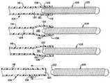
- FIG. 2is an enlarged, partially sectioned view showing the distal end of the coil deployment system prior to deployment of the coil;
- FIGS. 3 and 4illustrate the sequential steps in the radial expansion of the distal tip of the coil deployment system as the embolic coil is released.
- FIG. 5illustrates the distal tip of the coil deployment system after release of the embolic coil.
- FIG. 1generally illustrates the vascular occlusive coil deployment system 100 which is comprised of a catheter 104 having a proximal section 116 and a distal section 108 , a syringe 102 coupled to the proximal section 116 of the catheter 104 , and an embolic coil 106 partially disposed within the lumen of the distal section 108 of the catheter.
- the syringe 102includes a threaded piston 110 that is controlled by a handle 112 for infusing fluid into the interior of the catheter 104 .
- the catheter 104includes a winged hub 114 that aids in the insertion of the catheter into the vascular system of the body.
- FIG. 2illustrates in more detail the distal section 108 of the catheter 104 .
- a proximal end 118 of the embolic coil 106is disposed within the distal section 108 of the catheter 104 and is tightly held within the lumen 120 of this distal section 108 prior to the release of the coil.
- FIG. 2illustrates the vascular occlusive coil deployment system prior to activation of the piston of the syringe and prior to release of the coil.
- the embolic coil 106may take various forms and configurations and may even take the form of a randomly wound coil. With the helically wound coil as illustrated in FIG. 2, the coil is provided with a weld bead or seal plug 122 which is disposed in a lumen 123 which, extends throughout the length of the coil 106 . In addition, adjacent turns at the proximal end 118 of the coil 106 are welded together so that the welded turns of the coil in conjunction with the seal plug 122 provide a generally unitary structure. When the coil 106 is placed in fluid-tight engagement with the lumen 120 of the catheter 104 , the seal plug 122 serves to prevent the flow of fluid through the lumen 123 of the coil 106 .
- a small circular aperture 130is located just proximal to the seal plug 122 and extends radially through the wall of the distal section 108 of the catheter.
- the aperture 130provides a means for purging the catheter 104 of air prior to inserting the catheter into a patient.
- the aperture 130is sized such that fluids with a viscosity less than about 1 ⁇ 10 ⁇ 8 lb ⁇ s/in 2 will exit the catheter 104 at low pressures during purging, but fluids with a viscosity greater than about 1 ⁇ 10 ⁇ 8 lb ⁇ s/in 2 will have a restricted outflow so that sufficient fluid pressure can be built up in the distal section of the catheter to release the coil during coil deployment.
- the flow of airhaving a viscosity of about 2.6 ⁇ 10 ⁇ 9 lb ⁇ s/in 2
- the flow of saline solutionhaving a viscosity of about 1.74 ⁇ 10 ⁇ lb ⁇ s/in 2
- the purge pressuremeasured at the proximal section of the catheter, is in the range of about 50 psi to 125 psi, with about 90 psi to 110 psi being the preferred range.
- the cathetertakes up to 60 seconds using saline solution of 0.9% sodium chloride. More viscous solutions may be used, but will take longer to purge the catheter of air.
- the purging solutionshould preferably have a viscosity of about 1.74 ⁇ 10 ⁇ 7 lb ⁇ s/in 2 .
- the aperture 130should be located as close to the seal plug 122 as possible to allow as much air as possible to be purged from the lumen 120 of the catheter 104 . Elevation of the distal section during purging is not necessary.
- the aperturehas a diameter in the range between about 0.00095 inches to 0.0012 inches, with approximately 0.001 inches being preferred, and is formed using a heated wire. The aperture is located approximately 0.003 inches to 0.006 inches from the seal plug.
- the small geometry of the catheterresults in a loss in fluid pressure between the proximal section and the distal section.
- This lossdue primarily to the restricted flow of fluid through the small inner diameter of the catheter and the smaller purge hole in the distal section, is on the order of about 25%.
- accurate measurements of the pressure delivered to the distal sectionare difficult to measure.
- actual pressure measurementscan be taken at the proximal section of the catheter, while the pressure delivered to the distal section must be calculated.
- the deployment pressure, measured at the proximal sectionis typically in the range of about 150 psi to 565 psi, with about 400 psi being preferred.
- the actual deployment pressure applied at the distal endmust be calculated and is expected to be in the range of about 110 psi to 425 psi, with 250 psi being preferred.
- FIGS. 3 and 4generally illustrate the coil release mechanism in action for the vascular occlusive coil deployment system. More particularly, as shown in FIG. 3, when a hydraulic pressure is applied to an interior 124 of the catheter 104 the relatively low durometer distal section 108 of the catheter begins to expand outwardly. As the distal section 108 continues to expand there comes a point as illustrated in FIG. 4 in which the coil 106 becomes disengaged from the lumen of the distal section 108 and the coil is then released from the catheter and is deployed at that location within the vessel.
- the cathetermay then be withdrawn leaving the coil positioned at the desired site.
- the proximal section 116 and the distal section 108 of the catheter 104are formed of materials having different durometers. As may be appreciated, there are numerous materials that could be used to fabricate the proximal section 116 and distal section 108 of the catheter 104 .
- the proximal section 116is preferably formed from Vestimid material having a durometer in a range of about 62 D to 75 D, with a durometer of 75 D being preferred. This allows the proximal section to be sufficiently flexible to transverse the to vasculature of the human body, but sufficiently rigid to resist any outward expansion of the walls when a fluid pressure of approximately 250 psi is applied to the interior of the distal section of the catheter.
- the distal section 108 of the catheteris preferably formed from polymer material with a relatively low durometer.
- Low durometer polymer materialstypically exhibit the characteristic of expanding when a fluid pressure is applied to the interior of the catheter.
- the distal section 108is preferably formed from a block copolymer, such as Pebax material, having a durometer of between 25 D and 55 D, with a durometer of 40 D being preferred.
- heat bonding materials with significantly different durometersis typically achieved by bonding interposed layers of material with similar durometers.
- the proximal layerwith a durometer of 75 D
- an interposed layer of material(not shown) with a durometer of 55 D.
- the distal layerwith a durometer of 40 D, is then bonded to the layer of 55 D material.
- the vascular occlusive coil deployment systemit is possible to place an embolic coil very precisely at a desired location within a vessel. Once the coil has been positioned into the desired location by use of the catheter, the coil may be deployed by applying a fluid pressure to the interior of the catheter to thereby cause the catheter to release the coil and deposit the coil very accurately at the desired location.
Landscapes
- Health & Medical Sciences (AREA)
- Life Sciences & Earth Sciences (AREA)
- Surgery (AREA)
- Veterinary Medicine (AREA)
- Public Health (AREA)
- General Health & Medical Sciences (AREA)
- Engineering & Computer Science (AREA)
- Biomedical Technology (AREA)
- Heart & Thoracic Surgery (AREA)
- Animal Behavior & Ethology (AREA)
- Molecular Biology (AREA)
- Medical Informatics (AREA)
- Nuclear Medicine, Radiotherapy & Molecular Imaging (AREA)
- Vascular Medicine (AREA)
- Reproductive Health (AREA)
- Biophysics (AREA)
- Pulmonology (AREA)
- Anesthesiology (AREA)
- Hematology (AREA)
- Surgical Instruments (AREA)
Abstract
Description
1. Field of the Invention
The present invention relates generally to a medical device for placing an embolic coil at a preselected location within a vessel of the human body. More particularly, the present invention relates to a catheter system having a distal tip for retaining an embolic coil in order to transport the coil to a preselected position within the vessel and a control mechanism for releasing the embolic coil at the preselected position.
2. Description of the Prior Art
For many years, flexible catheters have been used to place various devices within the vessels of the human body. Such devices include dilation balloons, radiopaque fluids, liquid medications, and various types of occlusion devices like balloons and embolic coils.
In the case of balloon catheters, prior to introducing the catheter into a human body, it is desirable to purge air from the catheter with a liquid to prevent the air from being introduced into blood vessels. In the past, purging the catheter involved inflating the balloon section of the catheter to allow the air to escape out of the distal end of the balloon and then providing some mechanism to prevent air from reentering the balloon while it is being deflated.
U.S. Pat. No. 5,728,065 to Follmer, et al., discloses a balloon catheter with a vent hole disposed near the distal end of the balloon. The vent hole normally lays against the surface of an inner tubular member, preventing gases from entering the balloon. During purging, the balloon is inflated, the distal end of the balloon opens exposing the vent hole, and gases and a portion of the inflation medium flow out.
U.S. Pat. No. 4,811,737 to Rydell, discloses a balloon catheter with a slit in the distal portion of the tubular member. Fluid is injected into the catheter and flows through multiple inflation ports to expand the balloon. The purging fluid forces the air within the balloon through the slit in the tubular member.
U.S. patent application Ser. No. 09/400,680 to Barry, et al., entitled, “Heated Vascular Occlusion Coil Deployment System,” filed Sep. 21, 1999; U.S. patent application Ser. No. 09/399,714 to Barry, et al., entitled, “Embolic Coil Deployment System With Retaining Jaws,” filed Sep. 21, 1999; U.S. patent application Ser. No. 09/177,848 to Hieshima, entitled, “Embolic Coil Hydraulic Deployment System,” filed Oct. 21, 1998; U.S. patent application Ser. No. 09/256,161 to Lulo, entitled, “Embolic Coil Deployment System With Improved Embolic Coil,” filed Feb. 22, 1999; U.S. patent application Ser. No. 09/256,163 to Diaz, et al., entitled, “Embolic Coil Deployment System With Improved Embolic Coil,” filed Feb. 22, 1999; U.S. patent application Ser. No. 09/258,678 to Goodson, et al., entitled, “Embolic Coil Hydraulic Deployment System With Improved Syringe Injector,” filed Feb. 25, 1999; and U.S. patent application Ser. No. 09/257,742 to Lulo, et al., entitled, “Embolic Coil Hydraulic Deployment System Having Improved Catheter,” filed Feb. 24, 1999, are all assigned to the same assignee as the subject application and disclose embolic coil deployment systems for use in deploying an embolic device at a predetermined location within a vessel.
In accordance with the present invention, there is provided a vascular occlusive coil deployment system for use in placing a coil at a preselected site within a vessel including a catheter having a tubular wall and having a lumen extending throughout the length of the catheter. The catheter further includes a proximal section and a distal section. The distal section of the catheter is formed from a material which exhibits the characteristic that the wall of the distal section of the catheter expands outwardly when a liquid is applied within the lumen of the catheter. A syringe is coupled to the proximal section of the catheter for applying the liquid within the lumen of the catheter. The proximal end of an embolic coil is disposed in fluid-tight engagement within the lumen of the distal section of the catheter. When the liquid is applied within the lumen of the catheter, the wall of the distal section of the catheter expands outwardly and the proximal end of the embolic coil is released. At least one aperture is included for purging air from the lumen of the catheter to prevent the air from being introduced into the blood vessels. The aperture extends radially through the wall of the distal section of the catheter at a point proximal to the proximal end of the embolic coil. The aperture is sized such that air can pass through the aperture when fluid pressure is applied to the interior of the catheter but the flow of more viscous fluids is highly restricted.
In accordance with another aspect of the present invention, there is provided a vascular occlusive coil deployment system for use in placing a coil at a preselected site within a vessel including a catheter having a tubular wall and having a lumen extending throughout the length of the catheter. The catheter further includes a proximal section and a distal section. The distal section of the catheter is formed from a material which exhibits the characteristic that the wall of the distal section of the catheter expands outwardly when a liquid is applied within the lumen of the catheter. There is also provided a means for applying the liquid within the lumen of the catheter. The proximal end of an embolic coil is disposed in fluid-tight engagement within the lumen of the distal section of the catheter. When the liquid is applied within the lumen of the catheter, the wall of the distal section of the catheter expands outwardly, and the proximal end of the embolic coil is released. Finally, the vascular occlusive coil deployment system includes a means for purging air from the system.
In accordance with another aspect of the present invention, the means for applying a fluid pressure within the lumen of the catheter comprises a syringe coupled to the proximal section of the catheter.
In accordance with another aspect of the present invention, the purging means comprises at least one aperture extending radially through the wall of the distal section of the catheter at a point just proximal to the proximal end of the embolic coil.
In accordance with another aspect of the present invention, the aperture is sized such that the outflow is highly restricted for liquids having a viscosity greater than about 1×10⁻⁸lb·s/in2.
In accordance with another aspect of the present invention, the aperture is sized such that the highly restricted outflow of liquid produces a fluid pressure within the lumen of the distal section of the catheter of at least 250 psi.
In accordance with another aspect of the present invention, the aperture is circular and has a diameter between approximately 0.00095 inches and 0.0012 inches. Preferably, the diameter is approximately 0.001 inches.
In accordance with another aspect of the present invention, the aperture is located between about 0.003 inches and 0.006 inches from the proximal end of the embolic coil.
In accordance with another aspect of the present invention, the liquid applied within the lumen of the catheter exerts a fluid pressure within the lumen of the proximal section of the catheter between about 50 psi and 125 psi and thereby causes air to pass through the aperture in the distal section of the catheter.
In accordance with still another aspect of the present invention, the proximal section of the catheter and the distal section of the catheter are formed from substances with different durometers. The distal section is formed from a material having a durometer which is substantially lower than the durometer of the material used to form the proximal section. The proximal section of the catheter is formed from a polymer having a durometer between 62 D to 75 D and the distal section of the catheter is formed from a polymer having a durometer between about 25 D and 55 D. Preferably, the proximal section of the catheter is formed from a material having a durometer of about 75 D and the distal section of the catheter is formed from a material having a durometer of about 40 D.
In accordance with another aspect of the present invention, the liquid is formed of saline solution. Preferably, the saline solution includes about 0.9% sodium chloride.
FIG. 1 is an enlarged, partially sectioned view of the hydraulic vascular occlusive coil deployment system of the present invention;
FIG. 2 is an enlarged, partially sectioned view showing the distal end of the coil deployment system prior to deployment of the coil;
FIGS. 3 and 4 illustrate the sequential steps in the radial expansion of the distal tip of the coil deployment system as the embolic coil is released; and,
FIG. 5 illustrates the distal tip of the coil deployment system after release of the embolic coil.
FIG. 1 generally illustrates the vascular occlusivecoil deployment system 100 which is comprised of acatheter 104 having aproximal section 116 and adistal section 108, asyringe 102 coupled to theproximal section 116 of thecatheter 104, and anembolic coil 106 partially disposed within the lumen of thedistal section 108 of the catheter. As may be seen, thesyringe 102 includes a threaded piston110 that is controlled by ahandle 112 for infusing fluid into the interior of thecatheter 104. Also as illustrated, thecatheter 104 includes awinged hub 114 that aids in the insertion of the catheter into the vascular system of the body.
FIG. 2 illustrates in more detail thedistal section 108 of thecatheter 104. Aproximal end 118 of theembolic coil 106 is disposed within thedistal section 108 of thecatheter 104 and is tightly held within thelumen 120 of thisdistal section 108 prior to the release of the coil. As may be appreciated, FIG. 2 illustrates the vascular occlusive coil deployment system prior to activation of the piston of the syringe and prior to release of the coil.
Theembolic coil 106 may take various forms and configurations and may even take the form of a randomly wound coil. With the helically wound coil as illustrated in FIG. 2, the coil is provided with a weld bead or sealplug 122 which is disposed in alumen 123 which, extends throughout the length of thecoil 106. In addition, adjacent turns at theproximal end 118 of thecoil 106 are welded together so that the welded turns of the coil in conjunction with theseal plug 122 provide a generally unitary structure. When thecoil 106 is placed in fluid-tight engagement with thelumen 120 of thecatheter 104, theseal plug 122 serves to prevent the flow of fluid through thelumen 123 of thecoil 106.
A smallcircular aperture 130 is located just proximal to theseal plug 122 and extends radially through the wall of thedistal section 108 of the catheter. Theaperture 130 provides a means for purging thecatheter 104 of air prior to inserting the catheter into a patient. Theaperture 130 is sized such that fluids with a viscosity less than about 1×10⁻⁸lb·s/in2will exit thecatheter 104 at low pressures during purging, but fluids with a viscosity greater than about 1×10⁻⁸lb·s/in2will have a restricted outflow so that sufficient fluid pressure can be built up in the distal section of the catheter to release the coil during coil deployment. For example, the flow of air, having a viscosity of about 2.6×10⁻⁹lb·s/in2, would meet little resistance during purging while the flow of saline solution, having a viscosity of about 1.74×10−∂lb·s/in2, would be highly restricted. This highly restricted outflow allows the fluid pressure within the catheter to reach a deployment pressure of about 250 psi at the distal section. Typically, the purge pressure, measured at the proximal section of the catheter, is in the range of about 50 psi to 125 psi, with about 90 psi to 110 psi being the preferred range.
Purging the catheter takes up to 60 seconds using saline solution of 0.9% sodium chloride. More viscous solutions may be used, but will take longer to purge the catheter of air. For optimum operation of the vascular occlusive coil deployment system, the purging solution should preferably have a viscosity of about 1.74×10⁻⁷lb·s/in2.
As can be appreciated, theaperture 130 should be located as close to theseal plug 122 as possible to allow as much air as possible to be purged from thelumen 120 of thecatheter 104. Elevation of the distal section during purging is not necessary. In the preferred embodiment, the aperture has a diameter in the range between about 0.00095 inches to 0.0012 inches, with approximately 0.001 inches being preferred, and is formed using a heated wire. The aperture is located approximately 0.003 inches to 0.006 inches from the seal plug.
As can be appreciated, the small geometry of the catheter results in a loss in fluid pressure between the proximal section and the distal section. This loss, due primarily to the restricted flow of fluid through the small inner diameter of the catheter and the smaller purge hole in the distal section, is on the order of about 25%. To further complicate matters, accurate measurements of the pressure delivered to the distal section are difficult to measure. Thus, actual pressure measurements can be taken at the proximal section of the catheter, while the pressure delivered to the distal section must be calculated. For example, the deployment pressure, measured at the proximal section, is typically in the range of about 150 psi to 565 psi, with about 400 psi being preferred. The actual deployment pressure applied at the distal end must be calculated and is expected to be in the range of about 110 psi to 425 psi, with 250 psi being preferred.
FIGS. 3 and 4 generally illustrate the coil release mechanism in action for the vascular occlusive coil deployment system. More particularly, as shown in FIG. 3, when a hydraulic pressure is applied to an interior124 of thecatheter 104 the relatively low durometerdistal section 108 of the catheter begins to expand outwardly. As thedistal section 108 continues to expand there comes a point as illustrated in FIG. 4 in which thecoil 106 becomes disengaged from the lumen of thedistal section 108 and the coil is then released from the catheter and is deployed at that location within the vessel.
As illustrated in FIG. 5, when thecoil 106 has been released from thecatheter 104 the catheter may then be withdrawn leaving the coil positioned at the desired site.
In the preferred embodiment, theproximal section 116 and thedistal section 108 of thecatheter 104 are formed of materials having different durometers. As may be appreciated, there are numerous materials that could be used to fabricate theproximal section 116 anddistal section 108 of thecatheter 104. Theproximal section 116 is preferably formed from Vestimid material having a durometer in a range of about 62 D to 75 D, with a durometer of 75 D being preferred. This allows the proximal section to be sufficiently flexible to transverse the to vasculature of the human body, but sufficiently rigid to resist any outward expansion of the walls when a fluid pressure of approximately 250 psi is applied to the interior of the distal section of the catheter.
Thedistal section 108 of the catheter is preferably formed from polymer material with a relatively low durometer. Low durometer polymer materials typically exhibit the characteristic of expanding when a fluid pressure is applied to the interior of the catheter. In the preferred embodiment, when a fluid pressure of between about 150 psi and 565 psi is applied to the interior of the proximal section of the catheter, the walls of thedistal section 108 expand outwardly and thereby release theproximal end 118 of thecoil 106. In this embodiment, thedistal section 108 is preferably formed from a block copolymer, such as Pebax material, having a durometer of between 25 D and 55 D, with a durometer of 40 D being preferred. As is well known to the art, heat bonding materials with significantly different durometers is typically achieved by bonding interposed layers of material with similar durometers. In the preferred embodiment, the proximal layer, with a durometer of 75 D, is bonded to an interposed layer of material (not shown) with a durometer of 55 D. The distal layer, with a durometer of 40 D, is then bonded to the layer of 55 D material.
With the vascular occlusive coil deployment system, it is possible to place an embolic coil very precisely at a desired location within a vessel. Once the coil has been positioned into the desired location by use of the catheter, the coil may be deployed by applying a fluid pressure to the interior of the catheter to thereby cause the catheter to release the coil and deposit the coil very accurately at the desired location.
As is apparent, there are numerous modifications of the preferred embodiment described above that will be readily apparent to one skilled in the art. These include variations and modifications of the coil, including numerous coil-winding configurations or other types of implant devices, such as a vascular filter. Also, there are obviously variations of the syringe arrangement for applying a fluid pressure to the interior of the catheter, including a hydraulic injector, pump, and other fluid-pressure generating systems. Additionally, there are variations of the number and type of purging means, including one or more elliptical holes or slits. These modifications would be apparent to those having ordinary skill in the art to which this invention relates and are intended to be within the scope of the claims that follow.
Claims (33)
1. A vascular occlusive coil deployment system comprising:
a catheter having a tubular wall and having a lumen extending throughout the length of the catheter, said catheter further having a proximal section and a distal section, said distal section of the catheter being formed from a material which exhibits the characteristic that the wall of the distal section of the catheter expands outwardly when a liquid is applied within the lumen of the catheter;
a syringe coupled to said proximal section of the catheter for applying the liquid within the lumen of the catheter;
an embolic coil having a proximal end and a distal end, said proximal end of the embolic coil being disposed in fluid-tight engagement within said lumen of the distal section of the catheter, said proximal end of the embolic coil being released when the liquid is applied within the lumen of the catheter and the wall of the distal section of the catheter expands outwardly; and,
at least one aperture for purging air from said lumen of the catheter, said aperture extending radially through said wall of the distal section of the catheter at a point proximal to the proximal end of the embolic coil.
2. A vascular occlusive coil deployment system as defined inclaim 1 , wherein said aperture is sized such that an outflow of liquid is highly restricted for liquids having a viscosity greater than about 1×10⁻⁸lb·s/in2.
3. A vascular occlusive coil deployment system as defined inclaim 1 , wherein said aperture is sized such that the highly restricted outflow of liquid produces a fluid pressure within the lumen of the distal section of the catheter of about 250 psi.
4. A vascular occlusive coil deployment system as defined inclaim 1 , wherein said aperture is circular and has a diameter between approximately 0.00095 inches and 0.0012 inches.
5. A vascular occlusive coil deployment system as defined inclaim 4 , wherein said aperture is circular and has a diameter of approximately 0.001 inches.
6. A vascular occlusive coil deployment system as defined inclaim 4 , wherein said aperture is located between about 0.003 inches and 0.006 inches from said proximal end of the embolic coil.
7. A vascular occlusive coil deployment system as defined inclaim 6 , wherein said liquid applied within the lumen of the catheter exerts a fluid pressure within the lumen of the proximal section of the catheter between about 50 psi and 125 psi and thereby causes air to pass through the aperture in the distal section of the catheter.
8. A vascular occlusive coil deployment system as defined inclaim 7 , wherein said proximal section of the catheter and said distal section of the catheter are formed from materials with different durometers, said distal section being formed from a material having a durometer which is substantially lower than the durometer of the material used to form said proximal section.
9. A vascular occlusive coil deployment system as defined inclaim 8 , wherein said proximal section of the catheter is formed from a polymer having a durometer between 62 D to 75 D and said distal section of the catheter is formed from a polymer having a durometer of between about 25 D and 55 D.
10. A vascular occlusive coil deployment system as defined inclaim 9 , wherein said proximal section of the catheter is formed from a material having a durometer of about 75 D and the distal section of the catheter is formed from a material having a durometer of about 40 D.
11. A vascular occlusive coil deployment system as defined inclaim 8 , wherein said liquid comprises a saline solution.
12. A vascular occlusive coil deployment system as defined inclaim 11 , wherein said saline solution is comprised of about 0.9% sodium chloride.
13. A vascular occlusive coil deployment system comprising:
a catheter having a tubular wall and having a lumen extending throughout the length of the catheter, said catheter further having a proximal section and a distal section;
a syringe for applying a liquid within the lumen of the catheter;
an embolic coil having a proximal end and a distal end, said proximal end of the embolic coil being disposed in fluid-tight engagement within said lumen of the distal section of the catheter, said proximal end of the embolic coil being released when the liquid is applied within the lumen of the catheter and the wall of the distal section of the catheter expands outwardly; and,
an aperture extending radially through said wall of the distal section of the catheter at a point just proximal to the proximal end of the embolic coil.
14. A vascular occlusive coil deployment system as defined inclaim 13 , wherein said aperture is sized such that an outflow of liquid is highly restricted for liquids having a viscosity greater than about 1×10⁻⁸lb·s/in2.
15. A vascular occlusive coil deployment system as defined inclaim 13 , wherein said aperture is sized such that the highly restricted outflow of liquid produces a fluid pressure within the lumen of the distal section of the catheter of at least 250 psi.
16. A vascular occlusive coil deployment system as defined inclaim 13 , wherein said aperture is circular and has a diameter between approximately 0.00095 inches and 0.0012 inches.
17. A vascular occlusive coil deployment system as defined inclaim 16 , wherein said aperture is circular and has a diameter of approximately 0.001 inches.
18. A vascular occlusive coil deployment system as defined inclaim 16 , wherein said aperture is located between about 0.003 inches and 0.006 inches from said proximal end of the embolic coil.
19. A vascular occlusive coil deployment system as defined inclaim 18 , wherein said liquid applied within the lumen of the catheter exerts a fluid pressure within the lumen of the proximal section of the catheter between about 50 psi and 125 psi and thereby causes air to pass through an aperture in the distal section of the catheter.
20. A vascular occlusive coil deployment system as defined inclaim 19 , wherein said proximal section of the catheter and said distal section of the catheter are formed from materials with different durometers, said distal section being formed from a material having a durometer which is substantially lower than the durometer of the material used to form said proximal section.
21. A vascular occlusive coil deployment system as defined inclaim 20 , wherein said proximal section of the catheter is formed from a polymer having a durometer between 62 D to 75 D and said distal section of the catheter is formed from a polymer having a durometer of between about 25 D and 55 D.
22. A vascular occlusive coil deployment system as defined inclaim 21 , wherein said proximal section of the catheter is formed from a material having a durometer of about 75 D and the distal section of the catheter is formed from a material having a durometer of about 40 D.
23. A vascular occlusive coil deployment system as defined inclaim 21 , wherein said liquid comprises a saline solution.
24. A vascular occlusive coil deployment system as defined inclaim 23 , wherein said saline solution is comprised of about 0.9% sodium chloride.
25. A medical device deployment system comprising:
a catheter having a tubular wall and having a lumen extending throughout the length of the catheter, said catheter further having a proximal section and a distal section;
a syringe for applying a liquid within the lumen of the catheter;
a medical device having a proximal end and a distal end, said proximal end of the medical device being disposed in fluid-tight engagement within said lumen of the distal section of the catheter, said proximal end of the medical device being released when the liquid is applied within the lumen of the catheter; and,
an aperture extending radially through said wall of the distal section of the catheter at a point just proximal to the proximal end of the medical device.
26. A medical device deployment system as defined inclaim 25 , wherein said aperture is sized such that an outflow of liquid is highly restricted for liquids having a viscosity greater than about 1×10⁻⁸lb·s/in2.
27. A medical device deployment system as defined inclaim 25 , wherein said aperture is sized such that the highly restricted outflow of liquid produces a fluid pressure within the lumen of the distal section of the catheter of at least 250 psi.
28. A medical device deployment system as defined inclaim 25 , wherein said aperture is circular and has a diameter between approximately 0.00095 inches and 0.0012 inches.
29. A medical device deployment system as defined inclaim 28 , wherein said aperture is circular and has a diameter of approximately 0.001 inches.
30. A medical device deployment system as defined inclaim 28 , wherein said aperture is located between about 0.003 inches and 0.006 inches from said proximal end of the embolic coil.
31. A medical device deployment system as defined inclaim 30 , wherein said liquid applied within the lumen of the catheter exerts a fluid pressure within the lumen of the proximal section of the catheter between about 50 psi and 125 psi and thereby causes air to pass through the aperture in the distal section of the catheter.
32. A medical device deployment system as defined inclaim 31 , wherein said proximal section of the catheter and said distal section of the catheter are formed from materials with different durometers, said distal section being formed from a material having a durometer which is substantially lower than the durometer of the material used to form said proximal section.
33. A medical device deployment system as defined inclaim 32 , wherein said proximal section of the catheter is formed from a polymer having a durometer between 62 D to 75 D and said distal section of the catheter is formed from a polymer having a durometer of between about 25 D and 55 D.
Priority Applications (1)
| Application Number | Priority Date | Filing Date | Title |
|---|---|---|---|
| US09/515,944US6544225B1 (en) | 2000-02-29 | 2000-02-29 | Embolic coil hydraulic deployment system with purge mechanism |
Applications Claiming Priority (1)
| Application Number | Priority Date | Filing Date | Title |
|---|---|---|---|
| US09/515,944US6544225B1 (en) | 2000-02-29 | 2000-02-29 | Embolic coil hydraulic deployment system with purge mechanism |
Publications (1)
| Publication Number | Publication Date |
|---|---|
| US6544225B1true US6544225B1 (en) | 2003-04-08 |
Family
ID=24053444
Family Applications (1)
| Application Number | Title | Priority Date | Filing Date |
|---|---|---|---|
| US09/515,944Expired - LifetimeUS6544225B1 (en) | 2000-02-29 | 2000-02-29 | Embolic coil hydraulic deployment system with purge mechanism |
Country Status (1)
| Country | Link |
|---|---|
| US (1) | US6544225B1 (en) |
Cited By (37)
| Publication number | Priority date | Publication date | Assignee | Title |
|---|---|---|---|---|
| US20030093094A1 (en)* | 2001-11-15 | 2003-05-15 | Roberto Diaz | Small diameter deployment system with improved headpiece |
| US6689141B2 (en) | 2000-10-18 | 2004-02-10 | Microvention, Inc. | Mechanism for the deployment of endovascular implants |
| US20040204701A1 (en)* | 2000-10-18 | 2004-10-14 | Brian Cox | Mechanism for the deployment of endovascular implants |
| US20060276834A1 (en)* | 2005-06-02 | 2006-12-07 | Keith Balgobin | Stretch resistant embolic coil delivery system with spring release mechanism |
| US20060276832A1 (en)* | 2005-06-02 | 2006-12-07 | Keith Balgobin | Stretch resistant embolic coil delivery system with spring release mechanism |
| US20070005100A1 (en)* | 2005-06-30 | 2007-01-04 | Jones Donald K | Laser-based vascular occlusion device detachment system |
| US20070005099A1 (en)* | 2005-06-30 | 2007-01-04 | Jones Donald K | Chemically based vascular occlusion device deployment |
| US20070010850A1 (en)* | 2005-06-02 | 2007-01-11 | Keith Balgobin | Stretch resistant embolic coil delivery system with mechanical release mechanism |
| US20070010849A1 (en)* | 2005-06-02 | 2007-01-11 | Keith Balgobin | Embolic coil delivery system with spring wire release mechanism |
| US20070118172A1 (en)* | 2005-06-02 | 2007-05-24 | Keith Balgobin | Embolic coil delivery system with spring wire release mechanism |
| US20070270903A1 (en)* | 2005-06-02 | 2007-11-22 | Davis Iii Richard C | Stretch resistant embolic coil delivery system with combined mechanical and pressure release mechanism |
| US20070288050A1 (en)* | 2006-06-12 | 2007-12-13 | Richard Champion Davis | Modified headpiece for hydraulic coil deployment system |
| US20070288049A1 (en)* | 2006-06-12 | 2007-12-13 | Richard Champion Davis | Modified headpiece for hydraulic coil deployment system |
| US20080287982A1 (en)* | 2007-05-16 | 2008-11-20 | Boston Scientific Scimed, Inc. | Catheters for electrolytically detachable embolic devices |
| US20090163780A1 (en)* | 2007-12-21 | 2009-06-25 | Microvention, Inc. | System And Method For Locating Detachment Zone Of A Detachable Implant |
| US20090318948A1 (en)* | 2008-04-22 | 2009-12-24 | Coherex Medical, Inc. | Device, system and method for aneurysm embolization |
| US7708754B2 (en) | 2005-06-02 | 2010-05-04 | Codman & Shurtleff, Pc | Stretch resistant embolic coil delivery system with mechanical release mechanism |
| US7763077B2 (en) | 2003-12-24 | 2010-07-27 | Biomerix Corporation | Repair of spinal annular defects and annulo-nucleoplasty regeneration |
| US7803395B2 (en) | 2003-05-15 | 2010-09-28 | Biomerix Corporation | Reticulated elastomeric matrices, their manufacture and use in implantable devices |
| US20110022003A1 (en)* | 2009-07-21 | 2011-01-27 | Cook Incorporated | Detachable embolization coil |
| US8062325B2 (en) | 2006-07-31 | 2011-11-22 | Codman & Shurtleff, Inc. | Implantable medical device detachment system and methods of using the same |
| US8192676B2 (en) | 2004-02-12 | 2012-06-05 | Valspar Sourcing, Inc. | Container having barrier properties and method of manufacturing the same |
| US8192480B2 (en) | 2007-12-21 | 2012-06-05 | Microvention, Inc. | System and method of detecting implant detachment |
| US8328860B2 (en) | 2007-03-13 | 2012-12-11 | Covidien Lp | Implant including a coil and a stretch-resistant member |
| US8366720B2 (en) | 2006-07-31 | 2013-02-05 | Codman & Shurtleff, Inc. | Interventional medical device system having an elongation retarding portion and method of using the same |
| US8777979B2 (en) | 2006-04-17 | 2014-07-15 | Covidien Lp | System and method for mechanically positioning intravascular implants |
| US8777978B2 (en) | 2006-04-17 | 2014-07-15 | Covidien Lp | System and method for mechanically positioning intravascular implants |
| US8801747B2 (en) | 2007-03-13 | 2014-08-12 | Covidien Lp | Implant, a mandrel, and a method of forming an implant |
| US9011480B2 (en) | 2012-01-20 | 2015-04-21 | Covidien Lp | Aneurysm treatment coils |
| US9050095B2 (en) | 2004-09-22 | 2015-06-09 | Covidien Lp | Medical implant |
| US9198665B2 (en) | 2004-09-22 | 2015-12-01 | Covidien Lp | Micro-spiral implantation device |
| US9307996B2 (en) | 2005-12-13 | 2016-04-12 | DePuy Synthes Products, Inc. | Detachment actuator for use with medical device deployment systems |
| US9579104B2 (en) | 2011-11-30 | 2017-02-28 | Covidien Lp | Positioning and detaching implants |
| US9687245B2 (en) | 2012-03-23 | 2017-06-27 | Covidien Lp | Occlusive devices and methods of use |
| US9713475B2 (en) | 2014-04-18 | 2017-07-25 | Covidien Lp | Embolic medical devices |
| CN112274209A (en)* | 2020-12-29 | 2021-01-29 | 北京泰杰伟业科技有限公司 | Spring ring conveying and releasing system |
| US12114863B2 (en) | 2018-12-05 | 2024-10-15 | Microvention, Inc. | Implant delivery system |
Citations (72)
| Publication number | Priority date | Publication date | Assignee | Title |
|---|---|---|---|---|
| US2853070A (en) | 1955-10-05 | 1958-09-23 | Julliard Maurice | Syringes |
| US3334629A (en) | 1964-11-09 | 1967-08-08 | Bertram D Cohn | Occlusive device for inferior vena cava |
| US3353718A (en) | 1966-05-24 | 1967-11-21 | Fischer & Porter Co | Syringe, column or the like |
| US3635223A (en)* | 1969-12-02 | 1972-01-18 | Us Catheter & Instr Corp | Embolectomy catheter |
| US4512338A (en) | 1983-01-25 | 1985-04-23 | Balko Alexander B | Process for restoring patency to body vessels |
| US4734093A (en) | 1985-11-21 | 1988-03-29 | Sarcem S.A. | Remote controlled catheter having a micro-balloon |
| US4743230A (en) | 1985-09-05 | 1988-05-10 | Advanced Cardiovascular Systems, Inc. | Inflating and deflating device for balloon dilatation catheters |
| US4811737A (en) | 1987-11-16 | 1989-03-14 | Schneider-Shiley (Usa) Inc. | Self-purging balloon catheter |
| US4832692A (en) | 1986-10-14 | 1989-05-23 | Cordis Corporation | Inflation syringe assembly for percutaneous transluminal angioplasty |
| US4906241A (en) | 1987-11-30 | 1990-03-06 | Boston Scientific Corporation | Dilation balloon |
| US4919121A (en) | 1989-02-06 | 1990-04-24 | Schneider (Usa) Inc., A Pfizer Company | Inflation device for angioplasty catheter |
| US4938220A (en) | 1986-08-01 | 1990-07-03 | Advanced Cardiovascular Systems, Inc. | Catheter with split tip marker and method of manufacture |
| US4994069A (en) | 1988-11-02 | 1991-02-19 | Target Therapeutics | Vaso-occlusion coil and method |
| US4994071A (en) | 1989-05-22 | 1991-02-19 | Cordis Corporation | Bifurcating stent apparatus and method |
| US5035705A (en) | 1989-01-13 | 1991-07-30 | Scimed Life Systems, Inc. | Method of purging a balloon catheter |
| US5108407A (en) | 1990-06-08 | 1992-04-28 | Rush-Presbyterian St. Luke's Medical Center | Method and apparatus for placement of an embolic coil |
| US5122136A (en) | 1990-03-13 | 1992-06-16 | The Regents Of The University Of California | Endovascular electrolytically detachable guidewire tip for the electroformation of thrombus in arteries, veins, aneurysms, vascular malformations and arteriovenous fistulas |
| US5135486A (en) | 1990-08-31 | 1992-08-04 | Endosonics Corporation | Self-venting balloon dilitation catheter |
| US5137514A (en) | 1990-11-01 | 1992-08-11 | Accumed Systems, Inc. | Inflation syringe assembly for percutaneous transluminal angioplasty |
| US5167624A (en) | 1990-11-09 | 1992-12-01 | Catheter Research, Inc. | Embolus delivery system and method |
| US5168757A (en) | 1990-05-15 | 1992-12-08 | Ryder International Corporation | Fluid displacement and pressurizing device |
| US5201754A (en) | 1985-05-02 | 1993-04-13 | C. R. Bard, Inc. | Balloon dilatation catheter with varying radiopacity |
| US5217484A (en) | 1991-06-07 | 1993-06-08 | Marks Michael P | Retractable-wire catheter device and method |
| US5234437A (en) | 1991-12-12 | 1993-08-10 | Target Therapeutics, Inc. | Detachable pusher-vasoocclusion coil assembly with threaded coupling |
| US5250071A (en) | 1992-09-22 | 1993-10-05 | Target Therapeutics, Inc. | Detachable embolic coil assembly using interlocking clasps and method of use |
| US5261916A (en) | 1991-12-12 | 1993-11-16 | Target Therapeutics | Detachable pusher-vasoocclusive coil assembly with interlocking ball and keyway coupling |
| US5263964A (en) | 1992-05-06 | 1993-11-23 | Coil Partners Ltd. | Coaxial traction detachment apparatus and method |
| US5304195A (en) | 1991-12-12 | 1994-04-19 | Target Therapeutics, Inc. | Detachable pusher-vasoocclusive coil assembly with interlocking coupling |
| US5312415A (en) | 1992-09-22 | 1994-05-17 | Target Therapeutics, Inc. | Assembly for placement of embolic coils using frictional placement |
| US5334210A (en) | 1993-04-09 | 1994-08-02 | Cook Incorporated | Vascular occlusion assembly |
| US5336183A (en) | 1993-09-28 | 1994-08-09 | Imagyn Medical, Inc. | Inflator |
| US5342304A (en) | 1990-03-16 | 1994-08-30 | Advanced Cardiovascular Systems, Inc. | Inflation device for dilatation catheters |
| US5350397A (en) | 1992-11-13 | 1994-09-27 | Target Therapeutics, Inc. | Axially detachable embolic coil assembly |
| US5382259A (en) | 1992-10-26 | 1995-01-17 | Target Therapeutics, Inc. | Vasoocclusion coil with attached tubular woven or braided fibrous covering |
| US5403292A (en) | 1994-05-18 | 1995-04-04 | Schneider (Usa) Inc. | Thin wall catheter having enhanced torqueability characteristics |
| US5443478A (en) | 1992-09-02 | 1995-08-22 | Board Of Regents, The University Of Texas System | Multi-element intravascular occlusion device |
| US5470317A (en) | 1994-08-02 | 1995-11-28 | Design Standards Corporation | Swivel barrel assembly for inflation syringe |
| WO1996002100A1 (en) | 1994-07-08 | 1996-01-25 | Zenith Electronics Corporation | Trellis coded modulation system for hdtv |
| EP0717969A2 (en) | 1994-12-22 | 1996-06-26 | Target Therapeutics, Inc. | Implant delivery assembly with expandable coupling/decoupling mechanism |
| US5534007A (en) | 1995-05-18 | 1996-07-09 | Scimed Life Systems, Inc. | Stent deployment catheter with collapsible sheath |
| US5551954A (en) | 1991-10-04 | 1996-09-03 | Scimed Life Systems, Inc. | Biodegradable drug delivery vascular stent |
| EP0739607A2 (en) | 1995-04-28 | 1996-10-30 | Target Therapeutics, Inc. | Delivery catheter for electrolytically detachable implant |
| US5578074A (en) | 1994-12-22 | 1996-11-26 | Target Therapeutics, Inc. | Implant delivery method and assembly |
| US5582619A (en) | 1995-06-30 | 1996-12-10 | Target Therapeutics, Inc. | Stretch resistant vaso-occlusive coils |
| US5601600A (en) | 1995-09-08 | 1997-02-11 | Conceptus, Inc. | Endoluminal coil delivery system having a mechanical release mechanism |
| US5609608A (en) | 1995-10-27 | 1997-03-11 | Regents Of The University Of California | Miniature plastic gripper and fabrication method |
| US5647847A (en) | 1994-09-16 | 1997-07-15 | Scimed Life Systems, Inc. | Balloon catheter with improved pressure source |
| US5669931A (en)* | 1995-03-30 | 1997-09-23 | Target Therapeutics, Inc. | Liquid coils with secondary shape |
| US5690667A (en) | 1996-09-26 | 1997-11-25 | Target Therapeutics | Vasoocclusion coil having a polymer tip |
| WO1998002100A1 (en) | 1996-07-16 | 1998-01-22 | Anson Medical Limited | Surgical implants and delivery systems therefor |
| US5711909A (en)* | 1995-04-04 | 1998-01-27 | Cordis Corporation | Intravascular catheter and method of manufacturing |
| US5728065A (en)* | 1996-06-21 | 1998-03-17 | Medtronic, Inc. | Self-venting elastomeric balloon catheter |
| US5743905A (en)* | 1995-07-07 | 1998-04-28 | Target Therapeutics, Inc. | Partially insulated occlusion device |
| US5772668A (en) | 1992-06-18 | 1998-06-30 | American Biomed, Inc. | Apparatus for placing an endoprosthesis |
| US5797953A (en)* | 1994-03-18 | 1998-08-25 | Cook Incorporated | Helical embolization coil |
| US5800455A (en)* | 1993-04-19 | 1998-09-01 | Target Therapeutics, Inc. | Detachable embolic coil assembly |
| US5800454A (en)* | 1997-03-17 | 1998-09-01 | Sarcos, Inc. | Catheter deliverable coiled wire thromboginic apparatus and method |
| US5817057A (en) | 1996-09-13 | 1998-10-06 | Micro Interventional Systems, Inc. | Fluid propulsion steerable catheter and method |
| US5853418A (en) | 1995-06-30 | 1998-12-29 | Target Therapeutics, Inc. | Stretch resistant vaso-occlusive coils (II) |
| US5989242A (en)* | 1995-06-26 | 1999-11-23 | Trimedyne, Inc. | Therapeutic appliance releasing device |
| US6022326A (en)* | 1998-10-30 | 2000-02-08 | Lifepoint, Inc. | Device and method for automatic collection of whole saliva |
| US6024754A (en)* | 1996-01-18 | 2000-02-15 | Target Therapeutics Inc. | Aneurysm closure method |
| US6063100A (en)* | 1998-03-10 | 2000-05-16 | Cordis Corporation | Embolic coil deployment system with improved embolic coil |
| US6068644A (en)* | 1998-03-10 | 2000-05-30 | Cordis Corporation | Embolic coil hydraulic deployment system having improved catheter |
| US6074407A (en)* | 1997-10-14 | 2000-06-13 | Target Therapeutics, Inc. | Delivery catheter for occlusive implants |
| US6113622A (en)* | 1998-03-10 | 2000-09-05 | Cordis Corporation | Embolic coil hydraulic deployment system |
| US6117142A (en)* | 1998-03-10 | 2000-09-12 | Cordis Corporation | Embolic coil hydraulic deployment system with improved syringe injector |
| US6149664A (en)* | 1998-08-27 | 2000-11-21 | Micrus Corporation | Shape memory pusher introducer for vasoocclusive devices |
| US6165178A (en)* | 1997-08-29 | 2000-12-26 | Scimed Life Systems, Inc. | Fast detaching electrically isolated implant |
| US6183491B1 (en)* | 1998-03-10 | 2001-02-06 | Cordis Corporation | Embolic coil deployment system with improved embolic coil |
| US20010008976A1 (en)* | 1995-03-02 | 2001-07-19 | Lixiao Wang | Stent installation method using balloon catheter having stepped compliance curve |
| US6375669B1 (en)* | 1998-04-28 | 2002-04-23 | Microvention, Inc. | Apparatus and method for vascular embolization |
- 2000
- 2000-02-29USUS09/515,944patent/US6544225B1/ennot_activeExpired - Lifetime
Patent Citations (75)
| Publication number | Priority date | Publication date | Assignee | Title |
|---|---|---|---|---|
| US2853070A (en) | 1955-10-05 | 1958-09-23 | Julliard Maurice | Syringes |
| US3334629A (en) | 1964-11-09 | 1967-08-08 | Bertram D Cohn | Occlusive device for inferior vena cava |
| US3353718A (en) | 1966-05-24 | 1967-11-21 | Fischer & Porter Co | Syringe, column or the like |
| US3635223A (en)* | 1969-12-02 | 1972-01-18 | Us Catheter & Instr Corp | Embolectomy catheter |
| US4512338A (en) | 1983-01-25 | 1985-04-23 | Balko Alexander B | Process for restoring patency to body vessels |
| US5201754A (en) | 1985-05-02 | 1993-04-13 | C. R. Bard, Inc. | Balloon dilatation catheter with varying radiopacity |
| US4743230A (en) | 1985-09-05 | 1988-05-10 | Advanced Cardiovascular Systems, Inc. | Inflating and deflating device for balloon dilatation catheters |
| US4734093A (en) | 1985-11-21 | 1988-03-29 | Sarcem S.A. | Remote controlled catheter having a micro-balloon |
| US4938220A (en) | 1986-08-01 | 1990-07-03 | Advanced Cardiovascular Systems, Inc. | Catheter with split tip marker and method of manufacture |
| US4832692A (en) | 1986-10-14 | 1989-05-23 | Cordis Corporation | Inflation syringe assembly for percutaneous transluminal angioplasty |
| US4811737A (en) | 1987-11-16 | 1989-03-14 | Schneider-Shiley (Usa) Inc. | Self-purging balloon catheter |
| US4906241A (en) | 1987-11-30 | 1990-03-06 | Boston Scientific Corporation | Dilation balloon |
| US4994069A (en) | 1988-11-02 | 1991-02-19 | Target Therapeutics | Vaso-occlusion coil and method |
| US5035705A (en) | 1989-01-13 | 1991-07-30 | Scimed Life Systems, Inc. | Method of purging a balloon catheter |
| US4919121A (en) | 1989-02-06 | 1990-04-24 | Schneider (Usa) Inc., A Pfizer Company | Inflation device for angioplasty catheter |
| US4994071A (en) | 1989-05-22 | 1991-02-19 | Cordis Corporation | Bifurcating stent apparatus and method |
| US5122136A (en) | 1990-03-13 | 1992-06-16 | The Regents Of The University Of California | Endovascular electrolytically detachable guidewire tip for the electroformation of thrombus in arteries, veins, aneurysms, vascular malformations and arteriovenous fistulas |
| US5342304A (en) | 1990-03-16 | 1994-08-30 | Advanced Cardiovascular Systems, Inc. | Inflation device for dilatation catheters |
| US5168757A (en) | 1990-05-15 | 1992-12-08 | Ryder International Corporation | Fluid displacement and pressurizing device |
| US5108407A (en) | 1990-06-08 | 1992-04-28 | Rush-Presbyterian St. Luke's Medical Center | Method and apparatus for placement of an embolic coil |
| US5135486A (en) | 1990-08-31 | 1992-08-04 | Endosonics Corporation | Self-venting balloon dilitation catheter |
| US5137514A (en) | 1990-11-01 | 1992-08-11 | Accumed Systems, Inc. | Inflation syringe assembly for percutaneous transluminal angioplasty |
| US5167624A (en) | 1990-11-09 | 1992-12-01 | Catheter Research, Inc. | Embolus delivery system and method |
| US5217484A (en) | 1991-06-07 | 1993-06-08 | Marks Michael P | Retractable-wire catheter device and method |
| US5551954A (en) | 1991-10-04 | 1996-09-03 | Scimed Life Systems, Inc. | Biodegradable drug delivery vascular stent |
| US5261916A (en) | 1991-12-12 | 1993-11-16 | Target Therapeutics | Detachable pusher-vasoocclusive coil assembly with interlocking ball and keyway coupling |
| US5304195A (en) | 1991-12-12 | 1994-04-19 | Target Therapeutics, Inc. | Detachable pusher-vasoocclusive coil assembly with interlocking coupling |
| US5234437A (en) | 1991-12-12 | 1993-08-10 | Target Therapeutics, Inc. | Detachable pusher-vasoocclusion coil assembly with threaded coupling |
| US5263964A (en) | 1992-05-06 | 1993-11-23 | Coil Partners Ltd. | Coaxial traction detachment apparatus and method |
| US5772668A (en) | 1992-06-18 | 1998-06-30 | American Biomed, Inc. | Apparatus for placing an endoprosthesis |
| US5443478A (en) | 1992-09-02 | 1995-08-22 | Board Of Regents, The University Of Texas System | Multi-element intravascular occlusion device |
| US5312415A (en) | 1992-09-22 | 1994-05-17 | Target Therapeutics, Inc. | Assembly for placement of embolic coils using frictional placement |
| US5250071A (en) | 1992-09-22 | 1993-10-05 | Target Therapeutics, Inc. | Detachable embolic coil assembly using interlocking clasps and method of use |
| US5382259A (en) | 1992-10-26 | 1995-01-17 | Target Therapeutics, Inc. | Vasoocclusion coil with attached tubular woven or braided fibrous covering |
| US6190373B1 (en)* | 1992-11-13 | 2001-02-20 | Scimed Life Systems, Inc. | Axially detachable embolic coil assembly |
| US5350397A (en) | 1992-11-13 | 1994-09-27 | Target Therapeutics, Inc. | Axially detachable embolic coil assembly |
| US5334210A (en) | 1993-04-09 | 1994-08-02 | Cook Incorporated | Vascular occlusion assembly |
| US5800455A (en)* | 1993-04-19 | 1998-09-01 | Target Therapeutics, Inc. | Detachable embolic coil assembly |
| US6099546A (en)* | 1993-04-19 | 2000-08-08 | Target Therapeutics, Inc. | Detachable embolic coil assembly using interlocking hooks and slots |
| US5336183A (en) | 1993-09-28 | 1994-08-09 | Imagyn Medical, Inc. | Inflator |
| US5797953A (en)* | 1994-03-18 | 1998-08-25 | Cook Incorporated | Helical embolization coil |
| US5403292A (en) | 1994-05-18 | 1995-04-04 | Schneider (Usa) Inc. | Thin wall catheter having enhanced torqueability characteristics |
| WO1996002100A1 (en) | 1994-07-08 | 1996-01-25 | Zenith Electronics Corporation | Trellis coded modulation system for hdtv |
| US5470317A (en) | 1994-08-02 | 1995-11-28 | Design Standards Corporation | Swivel barrel assembly for inflation syringe |
| US5647847A (en) | 1994-09-16 | 1997-07-15 | Scimed Life Systems, Inc. | Balloon catheter with improved pressure source |
| US6238415B1 (en)* | 1994-12-22 | 2001-05-29 | Target Therapeutics, Inc | Implant delivery assembly with expandable coupling/decoupling mechanism |
| US5578074A (en) | 1994-12-22 | 1996-11-26 | Target Therapeutics, Inc. | Implant delivery method and assembly |
| EP0717969A2 (en) | 1994-12-22 | 1996-06-26 | Target Therapeutics, Inc. | Implant delivery assembly with expandable coupling/decoupling mechanism |
| US20010008976A1 (en)* | 1995-03-02 | 2001-07-19 | Lixiao Wang | Stent installation method using balloon catheter having stepped compliance curve |
| US5669931A (en)* | 1995-03-30 | 1997-09-23 | Target Therapeutics, Inc. | Liquid coils with secondary shape |
| US5711909A (en)* | 1995-04-04 | 1998-01-27 | Cordis Corporation | Intravascular catheter and method of manufacturing |
| EP0739607A2 (en) | 1995-04-28 | 1996-10-30 | Target Therapeutics, Inc. | Delivery catheter for electrolytically detachable implant |
| US5534007A (en) | 1995-05-18 | 1996-07-09 | Scimed Life Systems, Inc. | Stent deployment catheter with collapsible sheath |
| US5989242A (en)* | 1995-06-26 | 1999-11-23 | Trimedyne, Inc. | Therapeutic appliance releasing device |
| US5853418A (en) | 1995-06-30 | 1998-12-29 | Target Therapeutics, Inc. | Stretch resistant vaso-occlusive coils (II) |
| US5582619A (en) | 1995-06-30 | 1996-12-10 | Target Therapeutics, Inc. | Stretch resistant vaso-occlusive coils |
| US5743905A (en)* | 1995-07-07 | 1998-04-28 | Target Therapeutics, Inc. | Partially insulated occlusion device |
| US5601600A (en) | 1995-09-08 | 1997-02-11 | Conceptus, Inc. | Endoluminal coil delivery system having a mechanical release mechanism |
| US5609608A (en) | 1995-10-27 | 1997-03-11 | Regents Of The University Of California | Miniature plastic gripper and fabrication method |
| US6024754A (en)* | 1996-01-18 | 2000-02-15 | Target Therapeutics Inc. | Aneurysm closure method |
| US5728065A (en)* | 1996-06-21 | 1998-03-17 | Medtronic, Inc. | Self-venting elastomeric balloon catheter |
| WO1998002100A1 (en) | 1996-07-16 | 1998-01-22 | Anson Medical Limited | Surgical implants and delivery systems therefor |
| US5817057A (en) | 1996-09-13 | 1998-10-06 | Micro Interventional Systems, Inc. | Fluid propulsion steerable catheter and method |
| US5690667A (en) | 1996-09-26 | 1997-11-25 | Target Therapeutics | Vasoocclusion coil having a polymer tip |
| US5800454A (en)* | 1997-03-17 | 1998-09-01 | Sarcos, Inc. | Catheter deliverable coiled wire thromboginic apparatus and method |
| US6165178A (en)* | 1997-08-29 | 2000-12-26 | Scimed Life Systems, Inc. | Fast detaching electrically isolated implant |
| US6074407A (en)* | 1997-10-14 | 2000-06-13 | Target Therapeutics, Inc. | Delivery catheter for occlusive implants |
| US6063100A (en)* | 1998-03-10 | 2000-05-16 | Cordis Corporation | Embolic coil deployment system with improved embolic coil |
| US6117142A (en)* | 1998-03-10 | 2000-09-12 | Cordis Corporation | Embolic coil hydraulic deployment system with improved syringe injector |
| US6183491B1 (en)* | 1998-03-10 | 2001-02-06 | Cordis Corporation | Embolic coil deployment system with improved embolic coil |
| US6113622A (en)* | 1998-03-10 | 2000-09-05 | Cordis Corporation | Embolic coil hydraulic deployment system |
| US6068644A (en)* | 1998-03-10 | 2000-05-30 | Cordis Corporation | Embolic coil hydraulic deployment system having improved catheter |
| US6375669B1 (en)* | 1998-04-28 | 2002-04-23 | Microvention, Inc. | Apparatus and method for vascular embolization |
| US6149664A (en)* | 1998-08-27 | 2000-11-21 | Micrus Corporation | Shape memory pusher introducer for vasoocclusive devices |
| US6022326A (en)* | 1998-10-30 | 2000-02-08 | Lifepoint, Inc. | Device and method for automatic collection of whole saliva |
Cited By (64)
| Publication number | Priority date | Publication date | Assignee | Title |
|---|---|---|---|---|
| US6689141B2 (en) | 2000-10-18 | 2004-02-10 | Microvention, Inc. | Mechanism for the deployment of endovascular implants |
| US20040204701A1 (en)* | 2000-10-18 | 2004-10-14 | Brian Cox | Mechanism for the deployment of endovascular implants |
| US6811561B2 (en)* | 2001-11-15 | 2004-11-02 | Cordis Neurovascular, Inc. | Small diameter deployment system with improved headpiece |
| US20040236348A1 (en)* | 2001-11-15 | 2004-11-25 | Roberto Diaz | Small diameter deployment system with improved headpiece |
| US20030093094A1 (en)* | 2001-11-15 | 2003-05-15 | Roberto Diaz | Small diameter deployment system with improved headpiece |
| US8142471B2 (en) | 2001-11-15 | 2012-03-27 | Codman & Shurtleff, Inc. | Small diameter deployment system with improved headpiece |
| US20080221610A1 (en)* | 2001-11-15 | 2008-09-11 | Roberto Diaz | Small diameter deployment system with improved headpiece |
| US7803395B2 (en) | 2003-05-15 | 2010-09-28 | Biomerix Corporation | Reticulated elastomeric matrices, their manufacture and use in implantable devices |
| US7763077B2 (en) | 2003-12-24 | 2010-07-27 | Biomerix Corporation | Repair of spinal annular defects and annulo-nucleoplasty regeneration |
| US8192676B2 (en) | 2004-02-12 | 2012-06-05 | Valspar Sourcing, Inc. | Container having barrier properties and method of manufacturing the same |
| US9198665B2 (en) | 2004-09-22 | 2015-12-01 | Covidien Lp | Micro-spiral implantation device |
| US9050095B2 (en) | 2004-09-22 | 2015-06-09 | Covidien Lp | Medical implant |
| US20070010850A1 (en)* | 2005-06-02 | 2007-01-11 | Keith Balgobin | Stretch resistant embolic coil delivery system with mechanical release mechanism |
| US7799052B2 (en) | 2005-06-02 | 2010-09-21 | Codman & Shurtleff, Inc. | Stretch resistant embolic coil delivery system with mechanical release mechanism |
| US20070270903A1 (en)* | 2005-06-02 | 2007-11-22 | Davis Iii Richard C | Stretch resistant embolic coil delivery system with combined mechanical and pressure release mechanism |
| US20070118172A1 (en)* | 2005-06-02 | 2007-05-24 | Keith Balgobin | Embolic coil delivery system with spring wire release mechanism |
| US20070010849A1 (en)* | 2005-06-02 | 2007-01-11 | Keith Balgobin | Embolic coil delivery system with spring wire release mechanism |
| US20060276834A1 (en)* | 2005-06-02 | 2006-12-07 | Keith Balgobin | Stretch resistant embolic coil delivery system with spring release mechanism |
| US7985238B2 (en) | 2005-06-02 | 2011-07-26 | Codman & Shurtleff, Inc. | Embolic coil delivery system with spring wire release mechanism |
| US7819891B2 (en) | 2005-06-02 | 2010-10-26 | Codman & Shurtleff, Inc. | Stretch resistant embolic coil delivery system with spring release mechanism |
| US7819892B2 (en) | 2005-06-02 | 2010-10-26 | Codman & Shurtleff, Inc. | Embolic coil delivery system with spring wire release mechanism |
| US7708755B2 (en) | 2005-06-02 | 2010-05-04 | Codman & Shurtleff Inc. | Stretch resistant embolic coil delivery system with combined mechanical and pressure release mechanism |
| US7708754B2 (en) | 2005-06-02 | 2010-05-04 | Codman & Shurtleff, Pc | Stretch resistant embolic coil delivery system with mechanical release mechanism |
| US7811305B2 (en) | 2005-06-02 | 2010-10-12 | Codman & Shurtleff, Inc. | Stretch resistant embolic coil delivery system with spring release mechanism |
| US20060276832A1 (en)* | 2005-06-02 | 2006-12-07 | Keith Balgobin | Stretch resistant embolic coil delivery system with spring release mechanism |
| US7591833B2 (en) | 2005-06-30 | 2009-09-22 | Codman & Shurtleff, Inc. | Laser-based vascular occlusion device detachment system |
| US7780695B2 (en)* | 2005-06-30 | 2010-08-24 | Codman & Shurtleff, Inc. | Chemically based vascular occlusion device deployment |
| US20070005100A1 (en)* | 2005-06-30 | 2007-01-04 | Jones Donald K | Laser-based vascular occlusion device detachment system |
| US8206413B2 (en) | 2005-06-30 | 2012-06-26 | Codman & Shurtleff, Inc. | Chemically based vascular occlusion device deployment |
| US20070005099A1 (en)* | 2005-06-30 | 2007-01-04 | Jones Donald K | Chemically based vascular occlusion device deployment |
| US9307996B2 (en) | 2005-12-13 | 2016-04-12 | DePuy Synthes Products, Inc. | Detachment actuator for use with medical device deployment systems |
| US8795321B2 (en) | 2006-04-17 | 2014-08-05 | Covidien Lp | System and method for mechanically positioning intravascular implants |
| US8777978B2 (en) | 2006-04-17 | 2014-07-15 | Covidien Lp | System and method for mechanically positioning intravascular implants |
| US8795320B2 (en) | 2006-04-17 | 2014-08-05 | Covidien Lp | System and method for mechanically positioning intravascular implants |
| US8864790B2 (en) | 2006-04-17 | 2014-10-21 | Covidien Lp | System and method for mechanically positioning intravascular implants |
| US8777979B2 (en) | 2006-04-17 | 2014-07-15 | Covidien Lp | System and method for mechanically positioning intravascular implants |
| US8920457B2 (en)* | 2006-06-12 | 2014-12-30 | Depuy Synthes Products Llc | Modified headpiece for hydraulic coil deployment system |
| US20070288050A1 (en)* | 2006-06-12 | 2007-12-13 | Richard Champion Davis | Modified headpiece for hydraulic coil deployment system |
| US20070288049A1 (en)* | 2006-06-12 | 2007-12-13 | Richard Champion Davis | Modified headpiece for hydraulic coil deployment system |
| US20100262179A1 (en)* | 2006-06-12 | 2010-10-14 | Codman & Shurtleff, Inc. | Modified headpiece for hydraulic coil deployment system |
| US7766935B2 (en)* | 2006-06-12 | 2010-08-03 | Codman & Shurtleff, Inc. | Modified headpiece for hydraulic coil deployment system |
| US7670353B2 (en)* | 2006-06-12 | 2010-03-02 | Codman & Shurtleff, Inc. | Modified headpiece for hydraulic coil deployment system |
| US8062325B2 (en) | 2006-07-31 | 2011-11-22 | Codman & Shurtleff, Inc. | Implantable medical device detachment system and methods of using the same |
| US8366720B2 (en) | 2006-07-31 | 2013-02-05 | Codman & Shurtleff, Inc. | Interventional medical device system having an elongation retarding portion and method of using the same |
| US8328860B2 (en) | 2007-03-13 | 2012-12-11 | Covidien Lp | Implant including a coil and a stretch-resistant member |
| US9289215B2 (en) | 2007-03-13 | 2016-03-22 | Covidien Lp | Implant including a coil and a stretch-resistant member |
| US8801747B2 (en) | 2007-03-13 | 2014-08-12 | Covidien Lp | Implant, a mandrel, and a method of forming an implant |
| US20080287982A1 (en)* | 2007-05-16 | 2008-11-20 | Boston Scientific Scimed, Inc. | Catheters for electrolytically detachable embolic devices |
| US20090163780A1 (en)* | 2007-12-21 | 2009-06-25 | Microvention, Inc. | System And Method For Locating Detachment Zone Of A Detachable Implant |
| US8460332B2 (en) | 2007-12-21 | 2013-06-11 | Microvention, Inc. | System and method of detecting implant detachment |
| US10299755B2 (en) | 2007-12-21 | 2019-05-28 | Microvention, Inc. | System and method for locating detachment zone of a detachable implant |
| US8192480B2 (en) | 2007-12-21 | 2012-06-05 | Microvention, Inc. | System and method of detecting implant detachment |
| US9242070B2 (en) | 2007-12-21 | 2016-01-26 | MicronVention, Inc. | System and method for locating detachment zone of a detachable implant |
| US20090318948A1 (en)* | 2008-04-22 | 2009-12-24 | Coherex Medical, Inc. | Device, system and method for aneurysm embolization |
| US20110022003A1 (en)* | 2009-07-21 | 2011-01-27 | Cook Incorporated | Detachable embolization coil |
| US8118817B2 (en) | 2009-07-21 | 2012-02-21 | Cook Medical Technologies Llc | Detachable embolization coil |
| US9579104B2 (en) | 2011-11-30 | 2017-02-28 | Covidien Lp | Positioning and detaching implants |
| US10335155B2 (en) | 2011-11-30 | 2019-07-02 | Covidien Lp | Positioning and detaching implants |
| US9011480B2 (en) | 2012-01-20 | 2015-04-21 | Covidien Lp | Aneurysm treatment coils |
| US10893868B2 (en) | 2012-01-20 | 2021-01-19 | Covidien Lp | Aneurysm treatment coils |
| US9687245B2 (en) | 2012-03-23 | 2017-06-27 | Covidien Lp | Occlusive devices and methods of use |
| US9713475B2 (en) | 2014-04-18 | 2017-07-25 | Covidien Lp | Embolic medical devices |
| US12114863B2 (en) | 2018-12-05 | 2024-10-15 | Microvention, Inc. | Implant delivery system |
| CN112274209A (en)* | 2020-12-29 | 2021-01-29 | 北京泰杰伟业科技有限公司 | Spring ring conveying and releasing system |
Similar Documents
| Publication | Publication Date | Title |
|---|---|---|
| US6544225B1 (en) | Embolic coil hydraulic deployment system with purge mechanism | |
| CN113648518B (en) | Improved reinforced balloon catheter | |
| US6514264B1 (en) | Embolic coil hydraulic deployment system with purge mechanism | |
| JP3930188B2 (en) | Embolization coil hydraulic deployment system | |
| EP1316293B1 (en) | Aneurysm embolic device with an occlusive member | |
| JP3930189B2 (en) | Embolization coil deployment system with improved embolization coil | |
| EP1505929B1 (en) | An embolic protection system | |
| US4715378A (en) | Balloon catheter | |
| US6159197A (en) | Method and apparatus for treating body tissues and bodily fluid vessels | |
| US6379329B1 (en) | Detachable balloon embolization device and method | |
| JP4852201B2 (en) | Hydraulic placement system for small diameter embolic coils | |
| US8177806B2 (en) | Dilation balloon having a valved opening and related catheters and methods | |
| JP4472233B2 (en) | Embolization coil placement method and balloon catheter | |
| WO2015021065A1 (en) | Bulbous balloon with mechanical pressure regulator | |
| NO964206L (en) | Balloon catheter with side holes | |
| US7160266B2 (en) | Inflatable balloon catheter with purge mechanism and method | |
| JP2000217922A (en) | Balloon catheter device | |
| US4810455A (en) | Balloon catheter |
Legal Events
| Date | Code | Title | Description |
|---|---|---|---|
| AS | Assignment | Owner name:CORDIS CORPORATION, FLORIDA Free format text:ASSIGNMENT OF ASSIGNORS INTEREST;ASSIGNORS:LULO, ROBERT;NAGLREITER, BRETT E.;REEL/FRAME:010654/0149 Effective date:20000228 | |
| AS | Assignment | Owner name:CORDIS NEUROVASCULAR, INC., FLORIDA Free format text:ASSIGNMENT OF ASSIGNORS INTEREST;ASSIGNOR:CORIDS CORPORATION;REEL/FRAME:011122/0887 Effective date:20000821 | |
| STCF | Information on status: patent grant | Free format text:PATENTED CASE | |
| FPAY | Fee payment | Year of fee payment:4 | |
| AS | Assignment | Owner name:CODMAN & SHURTLEFF, INC., MASSACHUSETTS Free format text:MERGER;ASSIGNOR:CORDIS NEUROVASCULAR, INC.;REEL/FRAME:023032/0233 Effective date:20081216 Owner name:CODMAN & SHURTLEFF, INC.,MASSACHUSETTS Free format text:MERGER;ASSIGNOR:CORDIS NEUROVASCULAR, INC.;REEL/FRAME:023032/0233 Effective date:20081216 | |
| FPAY | Fee payment | Year of fee payment:8 | |
| FPAY | Fee payment | Year of fee payment:12 |