US6544224B1 - Lobed balloon catheter and method of use - Google Patents
Lobed balloon catheter and method of useDownload PDFInfo
- Publication number
- US6544224B1 US6544224B1US09/565,773US56577300AUS6544224B1US 6544224 B1US6544224 B1US 6544224B1US 56577300 AUS56577300 AUS 56577300AUS 6544224 B1US6544224 B1US 6544224B1
- Authority
- US
- United States
- Prior art keywords
- balloon
- lobes
- section
- configuration
- catheter
- Prior art date
- Legal status (The legal status is an assumption and is not a legal conclusion. Google has not performed a legal analysis and makes no representation as to the accuracy of the status listed.)
- Expired - Lifetime
Links
Images


Classifications
- A—HUMAN NECESSITIES
- A61—MEDICAL OR VETERINARY SCIENCE; HYGIENE
- A61M—DEVICES FOR INTRODUCING MEDIA INTO, OR ONTO, THE BODY; DEVICES FOR TRANSDUCING BODY MEDIA OR FOR TAKING MEDIA FROM THE BODY; DEVICES FOR PRODUCING OR ENDING SLEEP OR STUPOR
- A61M25/00—Catheters; Hollow probes
- A61M25/10—Balloon catheters
- A61M25/1027—Making of balloon catheters
- A61M25/1029—Production methods of the balloon members, e.g. blow-moulding, extruding, deposition or by wrapping a plurality of layers of balloon material around a mandril
- A—HUMAN NECESSITIES
- A61—MEDICAL OR VETERINARY SCIENCE; HYGIENE
- A61M—DEVICES FOR INTRODUCING MEDIA INTO, OR ONTO, THE BODY; DEVICES FOR TRANSDUCING BODY MEDIA OR FOR TAKING MEDIA FROM THE BODY; DEVICES FOR PRODUCING OR ENDING SLEEP OR STUPOR
- A61M25/00—Catheters; Hollow probes
- A61M25/10—Balloon catheters
- A61M25/1002—Balloon catheters characterised by balloon shape
- A61M2025/1004—Balloons with folds, e.g. folded or multifolded
- A—HUMAN NECESSITIES
- A61—MEDICAL OR VETERINARY SCIENCE; HYGIENE
- A61M—DEVICES FOR INTRODUCING MEDIA INTO, OR ONTO, THE BODY; DEVICES FOR TRANSDUCING BODY MEDIA OR FOR TAKING MEDIA FROM THE BODY; DEVICES FOR PRODUCING OR ENDING SLEEP OR STUPOR
- A61M25/00—Catheters; Hollow probes
- A61M25/10—Balloon catheters
- A61M25/1027—Making of balloon catheters
- A61M25/1038—Wrapping or folding devices for use with balloon catheters
Definitions
- This inventionrelates to the field of medical devices, and more particularly to a balloon catheter having a lobed balloon.
- a guiding catheterIn percutaneous transluminal coronary angioplasty (PTCA) procedures, a guiding catheter is advanced until the distal tip of the guiding catheter is seated in the ostium of a desired coronary artery.
- a guidewirepositioned within an inner lumen of an dilatation catheter, is first advanced out of the distal end of the guiding catheter into the patient's coronary artery until the distal end of the guidewire crosses a lesion to be dilated. Then the dilatation catheter having an inflatable balloon on the distal portion thereof is advanced into the patient's coronary anatomy, over the previously introduced guidewire, until the balloon of the dilatation catheter is properly positioned across the lesion.
- the dilatation balloonis inflated with liquid one or more times to a predetermined size at relatively high pressures (e.g. greater than 8 atmospheres) so that the stenosis is compressed against the arterial wall and the wall expanded to open up the passageway.
- relatively high pressurese.g. greater than 8 atmospheres
- the inflated diameter of the balloonis approximately the same diameter as the native diameter of the body lumen being dilated so as to complete the dilatation but not overexpand the artery wall.
- Substantial, uncontrolled expansion of the balloon against the vessel wallcan cause trauma to the vessel wall.
- blood flowresumes through the dilated artery and the dilatation catheter can be removed therefrom.
- angioplasty proceduresthere may be restenosis of the artery, i.e. reformation of the arterial blockage, which necessitates either another angioplasty procedure, or some other method of repairing or strengthening the dilated area.
- an intravascular prosthesisgenerally called a stent
- Stentsmay also be used to repair vessels having an intimal flap or dissection or to generally strengthen a weakened section of a vessel.
- Stentsare usually delivered to a desired location within a coronary artery in a contracted condition on a balloon of a catheter which is similar in many respects to a balloon angioplasty catheter, and expanded to a larger diameter by expansion of the balloon.
- the balloonis deflated to remove the catheter, and the stent is left in place within the artery at the site of the dilated lesion.
- Angioplasty balloonspreferably have high strength for inflation at relatively high pressure, and high flexibility and softness for improved ability to track the tortuous anatomy and cross lesions.
- the balloon complianceis chosen so that the balloon will have a desired amount of expansion during inflation.
- Compliant balloonsfor example balloons made from materials such as polyethylene, exhibit substantial stretching upon the application of tensile force.
- Noncompliant balloonsfor example balloons made from materials such as PET, exhibit relatively little stretching during inflation, and therefore provide controlled radial growth in response to an increase in inflation pressure within the working pressure range.
- balloonsmay be folded into a low profile configuration having balloon wings wrapped around the balloon prior to insertion into the patient.
- the balloontends to form a large flat wing or a bunched up irregular shape.
- the resulting relatively large profile of the deflated balloontends to complicate repositioning or removal of the balloon in the vasculature.
- the inventionis directed to a balloon catheter including an elongated shaft, and a balloon on a distal shaft section having at least a section which has an uninflated configuration or partially inflated with at least two lobes, and which has an inflated configuration with a cylindrical surface.
- the balloonhas a lobed inner surface and a lobed outer surface.
- the balloonhas a uniform wall thickness around a circumference of the lobed balloon section.
- the balloon wall thicknessmay be nonuniform around the balloon circumference.
- Each lobeforms a wing when the balloon is deflated.
- the deflated wingsprovide a deflated balloon with a relatively low profile, which facilitates advancement of the catheter balloon across a stenosis and the repositioning or removal of the balloon catheter within the patient's vasculature.
- the lobed balloon sectionpreferably extends at least the length of the working length of the balloon, and in one embodiment, the lobed section includes at least a portion of the tapers at one or both ends of the working length of the balloon. Additionally, in one embodiment, the lobed section includes a stepped, smaller diameter section proximal and/or distal to the working length.
- the lobesare disposed around the circumference of the balloon.
- the lobesmay have a variety of suitable shapes, such that the lobes preferentially collapse during deflation of the balloon to each form a deflated wing.
- each lobehas a curved or cylindrical shape.
- the lobeshave an angled configuration such as a triangular shape.
- the balloonhas about 2 to about 10 lobes, and preferably at least three lobes.
- the number of lobesdepends on the inflated diameter of the balloon within the working pressure range of the balloon. Specifically, larger diameter balloons will preferably have a greater number of lobes than a smaller diameter balloon, to thereby form a greater number of deflated wings. By increasing the number of deflated wings, the overall size of each wing is reduced to a point where the deflated balloon profile is sufficiently low.
- a balloon having a 3.0 mm inflated working outer diameterhas three lobes, and a balloon having a 4.0 to 6.0 mm inflated working outer diameter has four to six lobes.
- the number of lobeswill depend on the desired performance of the balloon, so that larger diameter balloon having an inflated working outer diameter of greater than 3.0 mm may have as little as 2 or 3 lobes.
- the ballooninflates into a cylindrical shape, which in a presently preferred embodiment forms when any substantial inflation pressure above atmospheric pressure is applied inside the balloon.
- the lobesare not identifiable when the balloon is inflated at elevated pressure, but are identifiable on the balloon when the balloon is at or near atmospheric pressure.
- the balloonis inflated to the cylindrical inflated configuration to perform a procedure such as dilatating a lesion, implanting a stent, or post-dilatation touch-up in the patient's blood vessel.
- the balloonis formed in a mold having the lobed shape.
- a polymeric tubeis placed in the mold and inflated therein, generally at elevated temperatures, to form the balloon having the lobed shape.
- the polymeric tubemay be configured to provide a balloon with substantially uniform or nonuniform wall thickness.
- both the outer surface of the balloon and the inner surface of the balloondevelop the lobed shape. Consequently, the balloon consistently deflates with wings formed by each lobe during removal of the inflation fluid from the balloon, and without the need to hold the interior of the balloon under vacuum after removal of the inflation fluid therefrom to force the wings to form. Additionally, the rupture and compliance characteristics of the balloon can be made uniform around the circumference of the balloon due to the uniform nature of the balloon wall.
- the balloon of the inventionprovides excellent ability to cross stenosed or otherwise narrow regions of the patient's vasculature, and deflates to a low profile configuration due to the uninflated configuration having lobes which form deflated wings. Additionally, the balloon inflates easily to a desired cylindrical cross section.
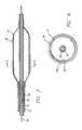
- FIG. 1is an elevational view, partially in section, of a balloon catheter which embodies features of the invention, illustrating the balloon in an uninflated configuration with lobes.
- FIG. 2is a transverse cross sectional view of the balloon shown in FIG. 1, taken along line 2 — 2 .
- FIG. 3is an enlarged longitudinal cross sectional view of a distal portion of the balloon catheter shown in FIG. 1, illustrating the balloon in an inflated configuration.
- FIG. 4is a transverse cross sectional view of the balloon shown in FIG. 3, taken along line 4 — 4 .
- FIG. 5is a transverse cross sectional view of an alternative configuration of a balloon catheter which embodies features of the invention, having a balloon with a nonuniform wall thickness, illustrating the balloon in an uninflated configuration.
- FIG. 6is a transverse cross sectional view of the alternative configuration of a balloon catheter shown in FIG. 5, illustrating the balloon in an inflated configuration.
- FIG. 7is a transverse cross sectional view of the balloon catheter shown in FIG. 1, illustrating the balloon in a deflated configuration with wings.
- FIG. 8illustrates the balloon shown in FIG. 7 with the wings wrapped around the catheter shaft.
- FIG. 9is a transverse cross sectional view of a mold useful in forming a balloon which embodies features of the invention.
- FIG. 10is a transverse cross sectional view of an alternative mold useful in forming a balloon which embodies features of the invention.
- FIG. 11is a transverse cross sectional view of a balloon catheter which embodies features of the invention, with a balloon having a star shaped cross section with triangular lobes, illustrating the balloon in an uninflated configuration.
- FIG. 1illustrates a balloon catheter 10 which embodies features of the invention.
- Catheter 10generally comprises an elongated catheter shaft 11 having an outer tubular member 12 and an inner tubular member 13 disposed within outer tubular member 12 .
- Inner tubular member 13defines a guidewire lumen 14 adapted to slidingly receive a guidewire 15 .
- the coaxial relationship between outer tubular member 12 and inner tubular member 13defines annular inflation lumen 16 .
- An inflatable balloon 17is disposed on a distal section of catheter shaft 11 , having a proximal end sealingly secured to the distal end of outer tubular member 12 and a distal end sealingly secured to the distal end of inner tubular member 13 so that its interior is in fluid communication with inflation lumen 16 .
- An adapter 18 at the proximal end of catheter shaft 11is configured to direct inflation fluid into inflation lumen 16 and to provide access to guidewire lumen 14 .
- FIG. 1illustrates balloon 17 in an uninflated configuration, i.e., at atmospheric pressure.
- Balloon 17has a working length 21 having an uninflated configuration with three lobes 22 (FIG. 2 ).
- FIG. 2showing a transverse cross section of the balloon catheter shown in FIG. 1, taken along line 2 — 2 , each lobe 22 is circumferentially displaced around the balloon 17 from adjacent lobes 22 , and the balloon working length 21 has an inner lobed surface 23 and an outer lobed surface 24 .
- the inner and outer surfaces 23 / 24 of the balloon working length 21have an irregular shape corresponding to the shape of the lobes, and do not have a cylindrical shape.
- the lobed section of the balloonextends beyond the ends of the working length 21 of the balloon 17 to the tapered region 26 of the balloon on either end of the working length.
- the lobed sectiondoes not extend beyond the working length 21 of the balloon 17 .
- the balloonhas a stepped profile when inflated, in which the balloon has a first tapered section which tapers from the proximal end of the working length to a proximal inflatable smaller diameter section located proximal to the working length, and/or a second tapered section at the distal end of the working length which tapers to a distal inflatable smaller diameter section located distal to the working length (not shown).
- the smaller diameter proximal and distal sectionsare preferably longitudinally aligned with the working length, but inflate to a smaller diameter of the working length.
- the balloonhas third and fourth tapered sections which taper from the smaller diameter proximal and distal sections, respectively, to the shaft section of the balloon secured to the catheter shaft.
- the lobed sections of the ballooninclude at least the smaller diameter proximal and distal sections of the balloon, and preferably extend to the proximal end of the third tapered section and to the distal end of the fourth tapered section.
- the balloon 17has three longitudinally extending sections 25 where adjacent lobes 22 meet, forming a junction between adjacent lobes 22 .
- the balloon interiorhas a radius at the longitudinally extending sections 25 which is less than a radius of the balloon interior between the longitudinally extending sections. The balloon deflates so that the sections 25 forming the junctions between lobes 22 are preferentially drawn inwardly toward the balloon center, and the sides of a lobe 22 are drawn together to form a wing.
- FIG. 3illustrates a distal portion of the balloon catheter 10 shown in FIG. 1, with the balloon 17 in an inflated configuration.
- Balloon 17has an inflated configuration with a cylindrical inner surface 23 and a cylindrical outer surface 24 , as shown in FIG. 4, illustrating a transverse cross section of the balloon catheter 10 shown in FIG. 3, taken along line 4 — 4 .
- an expandable stent 30is mounted on balloon 17 .
- Stent 30would typically be mounted on the working length 21 of the uninflated balloon 17 prior to introduction of the catheter 10 into the patient.
- the distal end of catheter 10may be advanced to a desired region of a patient's lumen in a conventional manner, and balloon 17 may be inflated to expand stent 30 , seating it in the lumen.
- the balloon 17is deflated, so that lobes 22 form deflated wings, and the balloon catheter 10 may be repositioned for another procedure or removed from the body lumen.
- the balloon working length 21has a uniform wall thickness around the circumference of the balloon.
- the balloon 17 illustrated in FIG. 1 having a uniform wall thicknessis formed from a uniform wall thickness parison.
- the term “uniform” as it is applied to the wall thickness of the balloon working length 21should be understood to include the slight variations in wall thickness typically found in catheter cylindrical balloons.
- the variations in the double wall thickness of a conventional 3.0 mm outer diameter balloonare typically about 0.0002 to about 0.0005 inches, preferably about 0.0003 to about 0.0004 inches.
- FIGS. 5 and 6An alternative embodiment having a nonuniform wall thickness is illustrated in FIGS. 5 and 6.
- FIG. 5illustrates balloon 117 in an uninflated configuration with three lobes 122 .
- Balloon 117has three longitudinally extending sections 125 where adjacent lobes 122 meet, forming a junction between adjacent lobes 122 .
- the longitudinally extending sections 125have a wall thickness which is greater than a wall thickness of the balloon working length 121 located between the longitudinally extending sections 125 .
- balloon 117deflates so that the thicker walled sections 125 forming the junction between adjacent lobes 122 preferentially collapses inwardly toward the balloon center and the sides of a lobe 122 are drawn together to form a wing.
- FIG. 6illustrates the balloon 117 in an inflated configuration, having a cylindrical outer surface 124 . In the embodiment illustrated in FIG.
- the inner surface 123 of the balloon working length 121has a nonuniform shape due to the nonuniform wall thickness.
- Factorssuch as the parison shape and the size of the differential between the outer diameter of the balloon at the lobe and the outer diameter of the balloon between two lobes in the uninflated configuration will affect whether the balloon 17 having a working length 21 with a uniform working length, or the balloon 117 having a working length 121 with a nonuniform wall thickness is produced.
- the discussions herein relating to balloon 17should be understood to apply to balloon 117 as well.
- FIG. 7illustrates the balloon 17 in a deflated configuration, with the lobes 22 forming deflated wings 40 .
- the three lobes 22collapse to form three wings 40 .
- the three wings 40provide a lower profile than would be present if the balloon deflated to form one or two larger wings.
- the physiciantypically removes the inflation fluid in the balloon by drawing the fluid out with an indeflator or syringe. Following removal of the inflation fluid, the balloon interior is typically held under vacuum.
- catheter 10may be repositioned or removed from the patient's body lumen, which typically involves withdrawing the catheter 10 into a guiding catheter (not shown), and wings 40 provide a low profile configuration that facilitates this procedure.
- FIG. 8illustrates the balloon after the wings 40 have been wrapped around the shaft 11 in preparation for introducing the catheter into the patient. As illustrated in FIG. 8, lobes of the balloon produce a winged balloon wherein the low profile of the winged balloon provides improved ability to cross stenosed and otherwise narrow regions of the patient's vasculature.
- FIG. 9illustrates a transverse cross section of a balloon mold 50 , useful in forming a balloon which embodies features of the invention.
- the moldhas an inner cavity 51 with three lobes 52 having concave surfaces.
- the inner cavity 51has rounded sections 53 with convex surfaces between the lobes 52 .
- Lobes 52 in the mold 50form lobes 22 of balloon 17
- sections 53 in the mold 50form the longitudinally extending sections 25 of balloon 17 .
- FIG. 10illustrates a transverse cross section of another embodiment of a balloon mold 60 , useful in forming a balloon which embodies features of the invention, having an inner cavity 61 and three lobes 62 with concave surfaces.
- the mold 60differs from the mold 50 in that concave surfaces of the lobes 62 directly meet to define the sections 63 between the lobes 62 .
- a polymeric tubular memberis placed in the mold 50 / 60 and expanded, typically at elevated temperature and pressure, and optionally under axially tension, to form the balloon.
- the mold used to form the balloonhas a radius of about 0.03 to about 0.2 inches, and more specifically about 0.045 to about 0.15 inches from the center of the mold to the inner surface of the mold at the midpoint of a lobe 52 / 62 , and a radius of about 0.01 to about 0.1 inches, more specifically about 0.02 to about 0.055 inches from the center of the mold to the inner surface of the mold at the midpoint of section 53 / 63 between two lobes, depending on the desired outer diameter of the balloon, which is typically about 1.5 to about 6.0 mm.
- the lobes 22comprise rounded projecting balloon portions.
- the round lobes 22 illustrated in FIG. 2provide improved refold to a low profile winged shape, easy inflation to the cylindrical inflated configuration, and ease of manufacture.
- a variety of suitable shapesmay be used for lobes 22 .
- the lobes 22are triangular, and form a five lobed, star-shaped balloon.
- the material forming the balloon 17is uniform, i.e., sections of the balloon are not formed of different material.
- the material forming the lobed section of the balloonis the same around the circumference of the balloon and the lobes are formed of the same material.
- the ballooncan be formed from a variety of suitable polymeric materials commonly used to form catheter balloons, including polyamides such as nylon, polyether block amides (PEBAX), polyurethane, polyurethane copolymers such as PELLETHANE, polyesters, and blends thereof.
- the interior of balloon 17does not form separately inflatable interior chambers.
- the lobes 22form a common balloon interior in fluid communication with inflation lumen 16 .
- the elongated shaft 11may have multiple separate inflation lumens, and balloon 17 may have multiple interior chambers therein (not shown).
- the dimensions of catheter 10are determined largely by the size of the guidewires to be employed and the size of the artery or other body lumen through which the catheter must pass or the size of the stent being delivered.
- the outer tubular member 12has an outer diameter of about 0.02 to about 0.04 inch (0.05 to 0.10 cm), usually about 0.037 inch (0.094 cm), an inner diameter of about 0.015 to about 0.035 inch (0.038 to 0.089 cm), usually about 0.03 inch (0.076 cm).
- the wall thickness of the outer tubular member 12can vary from about 0.002 to about 0.008 inch (0.0051 to 0.0201 cm), typically about 0.003 inch (0.0076 cm).
- the inner tubular member 13typically has an outer diameter of about 0.012 to about 0.016 inch (0.030 to 0.041 cm), usually about 0.014 inch (0.036 cm).
- the overall working length of the catheter 10may range from about 90 to about 160 cm, and is typically about 135 cm.
- balloon 17may have a length about 0.5 cm to about 4 cm and typically about 2 cm with an inflated working diameter of about 1 to about 10 mm, at inflation pressures of generally about 6 to about 16 atmospheres.
- the balloon catheter illustrated in FIG. 1is an over-the-wire catheter.
- Rapid exchange catheterstypically have an elongated shaft with a proximal end, a distal end with a balloon on a distal shaft section in fluid communication with an inflation lumen, a distal port in the distal end of the catheter, a proximal port spaced a substantial distance from the proximal end of the catheter closer to the distal end than to the proximal end, and a short guidewire lumen extending between the proximal and distal ports.
- the balloon 17may be configured for a variety of different uses, as for example as a dilatation balloon, stent delivery balloon, or radiation delivery catheter balloon.
- the inventionhas been discussed in terms of certain preferred embodiments.
- One of skill in the artwill recognize that various modifications may be made without departing from the scope of the invention.
- the lobescould alternatively be located on other balloon sections such as stepped smaller diameter sections of the balloon located proximal and/or distal to the working length.
- certain featuresmay be shown or discussed in relation to a particular embodiment, such individual features may be used on the various other embodiments of the invention.
Landscapes
- Health & Medical Sciences (AREA)
- Heart & Thoracic Surgery (AREA)
- Life Sciences & Earth Sciences (AREA)
- Engineering & Computer Science (AREA)
- Anesthesiology (AREA)
- Child & Adolescent Psychology (AREA)
- Biophysics (AREA)
- Pulmonology (AREA)
- Biomedical Technology (AREA)
- Hematology (AREA)
- Animal Behavior & Ethology (AREA)
- General Health & Medical Sciences (AREA)
- Public Health (AREA)
- Veterinary Medicine (AREA)
- Manufacturing & Machinery (AREA)
- Media Introduction/Drainage Providing Device (AREA)
Abstract
Description
Claims (26)
Priority Applications (5)
| Application Number | Priority Date | Filing Date | Title |
|---|---|---|---|
| US09/565,773US6544224B1 (en) | 2000-05-05 | 2000-05-05 | Lobed balloon catheter and method of use |
| PCT/US2001/014351WO2001085247A1 (en) | 2000-05-05 | 2001-05-03 | Lobed balloon catheter and method of use |
| AU2001257522AAU2001257522A1 (en) | 2000-05-05 | 2001-05-03 | Lobed balloon catheter and method of use |
| AU61830/01AAU6183001A (en) | 2000-05-05 | 2001-05-07 | Lobed balloon catheter and method of use |
| PCT/US2001/040692WO2001085229A2 (en) | 2000-05-05 | 2001-05-07 | Lobed balloon catheter and method of use |
Applications Claiming Priority (1)
| Application Number | Priority Date | Filing Date | Title |
|---|---|---|---|
| US09/565,773US6544224B1 (en) | 2000-05-05 | 2000-05-05 | Lobed balloon catheter and method of use |
Publications (1)
| Publication Number | Publication Date |
|---|---|
| US6544224B1true US6544224B1 (en) | 2003-04-08 |
Family
ID=24260028
Family Applications (1)
| Application Number | Title | Priority Date | Filing Date |
|---|---|---|---|
| US09/565,773Expired - LifetimeUS6544224B1 (en) | 2000-05-05 | 2000-05-05 | Lobed balloon catheter and method of use |
Country Status (3)
| Country | Link |
|---|---|
| US (1) | US6544224B1 (en) |
| AU (2) | AU2001257522A1 (en) |
| WO (2) | WO2001085247A1 (en) |
Cited By (60)
| Publication number | Priority date | Publication date | Assignee | Title |
|---|---|---|---|---|
| WO2004000387A3 (en)* | 2002-06-19 | 2004-10-14 | Univ Texas | Dialysis system for treatment of vulnerable patients and methods of use |
| US20040225318A1 (en)* | 2003-05-05 | 2004-11-11 | Tracee Eidenschink | Balloon catheter and method of making same |
| US20050059989A1 (en)* | 2003-09-17 | 2005-03-17 | Scimed Life Systems, Inc. | Balloon assembly with a torque |
| US20050075662A1 (en)* | 2003-07-18 | 2005-04-07 | Wesley Pedersen | Valvuloplasty catheter |
| US20050261723A1 (en)* | 2004-05-21 | 2005-11-24 | Medtronic Vascular, Inc. | Folded balloon for catheter |
| US20050277877A1 (en)* | 2001-03-26 | 2005-12-15 | Tom Motsenbocker | Balloon technology |
| US20060004328A1 (en)* | 2002-04-22 | 2006-01-05 | Abbott Laboratories Vascular Enterprises Limited | Balloon catheter |
| US20060015134A1 (en)* | 2004-07-13 | 2006-01-19 | Scimed Life Systems, Inc. | Balloon folding design and method and apparatus for making balloons |
| US20060112536A1 (en)* | 2003-09-15 | 2006-06-01 | Atrium Medical Corporation | Method of coating a folded medical device |
| US20060184191A1 (en)* | 2005-02-11 | 2006-08-17 | Boston Scientific Scimed, Inc. | Cutting balloon catheter having increased flexibility regions |
| US20070112300A1 (en)* | 2005-11-14 | 2007-05-17 | Roman Ricardo D | Balloon folding design, apparatus and method of making the same |
| US20080021386A1 (en)* | 2006-07-18 | 2008-01-24 | Nellcor Puritan Bennett Incorporated | Medical tube including an inflatable cuff having a notched collar |
| US20080114294A1 (en)* | 2006-11-14 | 2008-05-15 | Holman Thomas J | Medical balloon deflation |
| US20080177228A1 (en)* | 2007-01-24 | 2008-07-24 | Cook Incorporated | Preform and balloon having a non-uniform thickness |
| US20080249464A1 (en)* | 2007-04-05 | 2008-10-09 | Boston Scientific Scimed, Inc. | Catheter Having Internal Mechanisms to Encourage Balloon Re-folding |
| US20080319388A1 (en)* | 2007-06-21 | 2008-12-25 | David Slattery | Device delivery system with balloon-relative sheath positioning |
| US20090030510A1 (en)* | 2007-07-23 | 2009-01-29 | Ho Paul C | Methods and apparatus for percutaneous aortic valve replacement |
| US20090030503A1 (en)* | 2007-07-23 | 2009-01-29 | Ho Paul C | Method and apparatus for percutaneous aortic valve replacement |
| US20090090366A1 (en)* | 2007-09-20 | 2009-04-09 | Cuevas Brian J | Balloon cuff tracheostomy tube |
| US20090090365A1 (en)* | 2007-09-20 | 2009-04-09 | Cuevas Brian J | Balloon cuff tracheostomy tube with greater ease of insertion |
| US20090112159A1 (en)* | 2007-10-31 | 2009-04-30 | David Slattery | Delivery System With Profiled Sheath Having Balloon-Oriented Position |
| US20100022976A1 (en)* | 2007-02-22 | 2010-01-28 | Convatec Technologies Inc. | Seal for a rectal or ostomy appliance |
| US20100063442A1 (en)* | 2008-09-10 | 2010-03-11 | Cook Incorporated | Medical balloon having a resistance to circumferential tearing and method of producing the balloon |
| US20100094209A1 (en)* | 2008-10-10 | 2010-04-15 | Intervalve, Inc. | Valvuloplasty Catheter And Methods |
| US20100114018A1 (en)* | 2007-11-14 | 2010-05-06 | Boston Scientific Scimed, Inc. | Balloon bifurcated lumen treatment |
| US20110106184A1 (en)* | 2009-10-29 | 2011-05-05 | Kyphon Sarl | Anterior inflation balloon |
| US20110106007A1 (en)* | 2009-10-29 | 2011-05-05 | Kyphon Sarl | Anterior inflation balloon |
| US20110118703A1 (en)* | 1999-01-25 | 2011-05-19 | Herweck Steve A | Expandable fluoropolymer device for delivery of therapeutic agents and method of making |
| US20110210121A1 (en)* | 2007-02-13 | 2011-09-01 | Gateway Plastics, Inc. | Container system |
| US8043296B2 (en) | 2006-08-25 | 2011-10-25 | Kyphon Sarl | Apparatus and methods for use of expandable members in surgical applications |
| WO2012087837A1 (en)* | 2010-12-21 | 2012-06-28 | C. R. Bard, Inc. | Endotracheal tube having a recessed cuff, one or more suction apertures arranged therein, and/or a cuff having stiffeners and method of making and/or using the same |
| US20120239028A1 (en)* | 2011-03-18 | 2012-09-20 | Wallace Michael P | Selectively expandable operative element support structure and methods of use |
| WO2012162610A1 (en)* | 2011-05-26 | 2012-11-29 | Adn International, Llc | Expandable device for tissue collection from an aerodigestive body lumen |
| US20140046123A1 (en)* | 2012-08-10 | 2014-02-13 | Attenuex Technologies, Inc. | Methods and systems for performing a medical procedure |
| US8827953B2 (en) | 2013-01-15 | 2014-09-09 | Krishna Rocha-Singh | Apparatus and method for delivering intraluminal therapy |
| US8926620B2 (en) | 2006-08-25 | 2015-01-06 | Kyphon Sarl | Apparatus and methods for use of expandable members in surgical applications |
| US9242081B2 (en) | 2010-09-13 | 2016-01-26 | Intervalve, Inc. | Positionable valvuloplasty catheter |
| US9295510B2 (en) | 2013-02-06 | 2016-03-29 | Kyphon SÀRL | Device for performing a surgical procedure and methods of use |
| US20170312487A1 (en)* | 2015-01-26 | 2017-11-02 | Terumo Kabushiki Kaisha | Balloon catheter |
| WO2019050617A1 (en)* | 2017-09-07 | 2019-03-14 | Cryterion Medical, Inc. | Cryogenic balloon with greater size adjustability at lower inflation pressures |
| EP3473199A1 (en)* | 2017-10-16 | 2019-04-24 | Medtronic Holding Company Sàrl | Curved inflatable bone tamp with variable wall thickness |
| US10327880B2 (en) | 2000-04-14 | 2019-06-25 | Attenuex Technologies, Inc. | Attenuation device for use in an anatomical structure |
| US10383510B2 (en) | 2000-04-14 | 2019-08-20 | Solace Therapeutics, Inc. | Implant with high vapor pressure medium |
| US10772995B2 (en) | 2004-09-28 | 2020-09-15 | Atrium Medical Corporation | Cross-linked fatty acid-based biomaterials |
| US10792312B2 (en) | 2004-09-28 | 2020-10-06 | Atrium Medical Corporation | Barrier layer |
| US10814043B2 (en) | 2004-09-28 | 2020-10-27 | Atrium Medical Corporation | Cross-linked fatty acid-based biomaterials |
| US10864304B2 (en) | 2009-08-11 | 2020-12-15 | Atrium Medical Corporation | Anti-infective antimicrobial-containing biomaterials |
| US10888617B2 (en) | 2012-06-13 | 2021-01-12 | Atrium Medical Corporation | Cured oil-hydrogel biomaterial compositions for controlled drug delivery |
| US10993755B2 (en) | 2016-04-26 | 2021-05-04 | Medtronic Holding Company Sàrl | Inflatable bone tamp with flow control and methods of use |
| US11083823B2 (en) | 2005-09-28 | 2021-08-10 | Atrium Medical Corporation | Tissue-separating fatty acid adhesion barrier |
| US11097035B2 (en) | 2010-07-16 | 2021-08-24 | Atrium Medical Corporation | Compositions and methods for altering the rate of hydrolysis of cured oil-based materials |
| US11166929B2 (en) | 2009-03-10 | 2021-11-09 | Atrium Medical Corporation | Fatty-acid based particles |
| US11197981B2 (en) | 2019-02-07 | 2021-12-14 | Solace Therapeutics, Inc. | Pressure attenuation device |
| US11229466B2 (en) | 2018-01-12 | 2022-01-25 | KyphEZE, Inc. | Bone expansion systems and methods |
| WO2022122762A1 (en) | 2020-12-08 | 2022-06-16 | Ridgeback Technologies Ltd. | Balloon catheters |
| US11464949B2 (en) | 2018-04-12 | 2022-10-11 | The Regents Of The University Of Michigan | System for effecting and controlling oscillatory pressure within balloon catheters for fatigue fracture of calculi |
| US11484355B2 (en) | 2020-03-02 | 2022-11-01 | Medtronic Holding Company Sàrl | Inflatable bone tamp and method for use of inflatable bone tamp |
| US11744630B2 (en) | 2015-01-09 | 2023-09-05 | Medtronic Holding Company Sàrl | Tumor ablation system |
| US12279782B2 (en) | 2021-02-04 | 2025-04-22 | Amplitude Vascular Systems, Inc. | Pulsatile balloon catheter systems and methods of using the same |
| CN120586260A (en)* | 2025-08-07 | 2025-09-05 | 鼎科医疗技术(苏州)有限公司 | High-pressure resistant foldable balloon, manufacturing method thereof, and balloon dilation catheter |
Families Citing this family (4)
| Publication number | Priority date | Publication date | Assignee | Title |
|---|---|---|---|---|
| WO2004045403A1 (en)* | 2002-11-19 | 2004-06-03 | Rhinometrics A/S | Device and method for determining the opening pressure of occlusions in human or animal body cavities |
| US20090209908A1 (en)* | 2007-09-20 | 2009-08-20 | Cuevas Brian J | Tubular workpiece for producing an improved balloon cuff tracheostomy tube |
| DE102008008925A1 (en)* | 2008-02-13 | 2009-08-20 | Biotronik Vi Patent Ag | Catheter, intraluminal endoprosthesis delivery system, and method of making the same |
| US10058371B2 (en) | 2015-11-18 | 2018-08-28 | Medtronic Cryocath Lp | Multi-lobe balloon for cryoablation |
Citations (32)
| Publication number | Priority date | Publication date | Assignee | Title |
|---|---|---|---|---|
| US2078686A (en)* | 1935-07-29 | 1937-04-27 | Louis Janisky | Internal orifice thermal dilator and medicator |
| US3459175A (en)* | 1966-04-08 | 1969-08-05 | Roscoe E Miller | Medical device for control of enemata |
| US4141364A (en)* | 1977-03-18 | 1979-02-27 | Jorge Schultze | Expandable endotracheal or urethral tube |
| FR2529083A2 (en) | 1981-03-27 | 1983-12-30 | Farcot Jean Christian | Catheter for recycling arterial blood to treat infarction - of material with elastic memory e.g. PVC and cranked to facilitate insertion |
| US4941877A (en) | 1989-01-26 | 1990-07-17 | Cordis Corporation | Balloon catheter |
| US5037392A (en)* | 1989-06-06 | 1991-08-06 | Cordis Corporation | Stent-implanting balloon assembly |
| US5087246A (en) | 1988-12-29 | 1992-02-11 | C. R. Bard, Inc. | Dilation catheter with fluted balloon |
| US5163989A (en) | 1990-08-27 | 1992-11-17 | Advanced Cardiovascular Systems, Inc. | Method for forming a balloon mold and the use of such mold |
| US5195970A (en) | 1991-04-26 | 1993-03-23 | Gahara William J | Collapsible balloon catheters |
| US5207700A (en)* | 1988-08-08 | 1993-05-04 | Scimed Life Systems, Inc. | Polyimide balloon catheter and method of forming a balloon therefor |
| US5226887A (en) | 1992-02-07 | 1993-07-13 | Interventional Technologies, Inc. | Collapsible folding angioplasty balloon |
| US5250070A (en)* | 1991-05-28 | 1993-10-05 | Parodi Juan C | Less traumatic angioplasty balloon for arterial dilatation |
| US5318587A (en) | 1989-08-25 | 1994-06-07 | C. R. Bard, Inc. | Pleated balloon dilatation catheter and method of use |
| US5320634A (en)* | 1990-07-03 | 1994-06-14 | Interventional Technologies, Inc. | Balloon catheter with seated cutting edges |
| US5336234A (en)* | 1992-04-17 | 1994-08-09 | Interventional Technologies, Inc. | Method and apparatus for dilatation of a stenotic vessel |
| US5350361A (en) | 1993-11-10 | 1994-09-27 | Medtronic, Inc. | Tri-fold balloon for dilatation catheter and related method |
| US5397307A (en) | 1993-12-07 | 1995-03-14 | Schneider (Usa) Inc. | Drug delivery PTCA catheter and method for drug delivery |
| US5456666A (en) | 1994-04-26 | 1995-10-10 | Boston Scientific Corp | Medical balloon folding into predetermined shapes and method |
| US5458572A (en) | 1994-07-01 | 1995-10-17 | Boston Scientific Corp. | Catheter with balloon folding into predetermined configurations and method of manufacture |
| US5490839A (en) | 1993-09-20 | 1996-02-13 | Scimed Life Systems, Inc. | Catheter balloon with retraction coating |
| US5496276A (en) | 1993-09-20 | 1996-03-05 | Scimed Life Systems, Inc. | Catheter balloon with retraction coating |
| EP0737488A1 (en) | 1995-04-10 | 1996-10-16 | Cordis Europa N.V. | Balloon catheter with lobated balloon and method for manufacturing such a catheter |
| WO1997025093A1 (en) | 1996-01-04 | 1997-07-17 | Leocor, Inc. | Fluted balloon catheter |
| US5718684A (en) | 1996-05-24 | 1998-02-17 | Gupta; Mukesh | Multi-lobed balloon catheter |
| US5738901A (en) | 1993-09-20 | 1998-04-14 | Scimed Life Systems, Inc. | Catheter balloon with retraction coating |
| US5746745A (en)* | 1993-08-23 | 1998-05-05 | Boston Scientific Corporation | Balloon catheter |
| US5792300A (en) | 1994-01-21 | 1998-08-11 | Cordis Corporation | Perfusion catheter and striped extrusion method of manufacture |
| US5792172A (en) | 1996-12-23 | 1998-08-11 | Isostent, Inc. | Multifold balloon for stent deployment |
| US5902268A (en) | 1990-05-11 | 1999-05-11 | Saab; Mark A. | Heat transfer catheter apparatus and method of making and using same |
| US5954740A (en) | 1996-09-23 | 1999-09-21 | Boston Scientific Corporation | Catheter balloon having raised radial segments |
| US6013055A (en) | 1997-11-13 | 2000-01-11 | Boston Scientific Corporation | Catheter balloon having selected folding characteristics |
| US6033380A (en) | 1998-02-13 | 2000-03-07 | Cordis Corporation | Six-pleated catheter balloon and device for forming same |
- 2000
- 2000-05-05USUS09/565,773patent/US6544224B1/ennot_activeExpired - Lifetime
- 2001
- 2001-05-03AUAU2001257522Apatent/AU2001257522A1/ennot_activeAbandoned
- 2001-05-03WOPCT/US2001/014351patent/WO2001085247A1/enactiveApplication Filing
- 2001-05-07WOPCT/US2001/040692patent/WO2001085229A2/ennot_activeApplication Discontinuation
- 2001-05-07AUAU61830/01Apatent/AU6183001A/ennot_activeWithdrawn
Patent Citations (33)
| Publication number | Priority date | Publication date | Assignee | Title |
|---|---|---|---|---|
| US2078686A (en)* | 1935-07-29 | 1937-04-27 | Louis Janisky | Internal orifice thermal dilator and medicator |
| US3459175A (en)* | 1966-04-08 | 1969-08-05 | Roscoe E Miller | Medical device for control of enemata |
| US4141364A (en)* | 1977-03-18 | 1979-02-27 | Jorge Schultze | Expandable endotracheal or urethral tube |
| FR2529083A2 (en) | 1981-03-27 | 1983-12-30 | Farcot Jean Christian | Catheter for recycling arterial blood to treat infarction - of material with elastic memory e.g. PVC and cranked to facilitate insertion |
| US5207700A (en)* | 1988-08-08 | 1993-05-04 | Scimed Life Systems, Inc. | Polyimide balloon catheter and method of forming a balloon therefor |
| US5087246A (en) | 1988-12-29 | 1992-02-11 | C. R. Bard, Inc. | Dilation catheter with fluted balloon |
| US4941877A (en) | 1989-01-26 | 1990-07-17 | Cordis Corporation | Balloon catheter |
| US5037392A (en)* | 1989-06-06 | 1991-08-06 | Cordis Corporation | Stent-implanting balloon assembly |
| US5318587A (en) | 1989-08-25 | 1994-06-07 | C. R. Bard, Inc. | Pleated balloon dilatation catheter and method of use |
| US5902268A (en) | 1990-05-11 | 1999-05-11 | Saab; Mark A. | Heat transfer catheter apparatus and method of making and using same |
| US5320634A (en)* | 1990-07-03 | 1994-06-14 | Interventional Technologies, Inc. | Balloon catheter with seated cutting edges |
| US5163989A (en) | 1990-08-27 | 1992-11-17 | Advanced Cardiovascular Systems, Inc. | Method for forming a balloon mold and the use of such mold |
| US5195970A (en) | 1991-04-26 | 1993-03-23 | Gahara William J | Collapsible balloon catheters |
| US5250070A (en)* | 1991-05-28 | 1993-10-05 | Parodi Juan C | Less traumatic angioplasty balloon for arterial dilatation |
| US5226887A (en) | 1992-02-07 | 1993-07-13 | Interventional Technologies, Inc. | Collapsible folding angioplasty balloon |
| US5336234A (en)* | 1992-04-17 | 1994-08-09 | Interventional Technologies, Inc. | Method and apparatus for dilatation of a stenotic vessel |
| US5746745A (en)* | 1993-08-23 | 1998-05-05 | Boston Scientific Corporation | Balloon catheter |
| US5496276A (en) | 1993-09-20 | 1996-03-05 | Scimed Life Systems, Inc. | Catheter balloon with retraction coating |
| US5738901A (en) | 1993-09-20 | 1998-04-14 | Scimed Life Systems, Inc. | Catheter balloon with retraction coating |
| US5490839A (en) | 1993-09-20 | 1996-02-13 | Scimed Life Systems, Inc. | Catheter balloon with retraction coating |
| US5350361A (en) | 1993-11-10 | 1994-09-27 | Medtronic, Inc. | Tri-fold balloon for dilatation catheter and related method |
| US5397307A (en) | 1993-12-07 | 1995-03-14 | Schneider (Usa) Inc. | Drug delivery PTCA catheter and method for drug delivery |
| US5792300A (en) | 1994-01-21 | 1998-08-11 | Cordis Corporation | Perfusion catheter and striped extrusion method of manufacture |
| US5478319A (en)* | 1994-04-26 | 1995-12-26 | Boston Scientific Corp. | Medical balloon folding into predetermined shapes and method |
| US5456666A (en) | 1994-04-26 | 1995-10-10 | Boston Scientific Corp | Medical balloon folding into predetermined shapes and method |
| US5458572A (en) | 1994-07-01 | 1995-10-17 | Boston Scientific Corp. | Catheter with balloon folding into predetermined configurations and method of manufacture |
| EP0737488A1 (en) | 1995-04-10 | 1996-10-16 | Cordis Europa N.V. | Balloon catheter with lobated balloon and method for manufacturing such a catheter |
| WO1997025093A1 (en) | 1996-01-04 | 1997-07-17 | Leocor, Inc. | Fluted balloon catheter |
| US5718684A (en) | 1996-05-24 | 1998-02-17 | Gupta; Mukesh | Multi-lobed balloon catheter |
| US5954740A (en) | 1996-09-23 | 1999-09-21 | Boston Scientific Corporation | Catheter balloon having raised radial segments |
| US5792172A (en) | 1996-12-23 | 1998-08-11 | Isostent, Inc. | Multifold balloon for stent deployment |
| US6013055A (en) | 1997-11-13 | 2000-01-11 | Boston Scientific Corporation | Catheter balloon having selected folding characteristics |
| US6033380A (en) | 1998-02-13 | 2000-03-07 | Cordis Corporation | Six-pleated catheter balloon and device for forming same |
Cited By (124)
| Publication number | Priority date | Publication date | Assignee | Title |
|---|---|---|---|---|
| US9050442B2 (en) | 1999-01-25 | 2015-06-09 | Atrium Medical Corporation | Expandable fluoropolymer device for delivery of therapeutic agents and method of making |
| US20110118703A1 (en)* | 1999-01-25 | 2011-05-19 | Herweck Steve A | Expandable fluoropolymer device for delivery of therapeutic agents and method of making |
| US10383510B2 (en) | 2000-04-14 | 2019-08-20 | Solace Therapeutics, Inc. | Implant with high vapor pressure medium |
| US10327880B2 (en) | 2000-04-14 | 2019-06-25 | Attenuex Technologies, Inc. | Attenuation device for use in an anatomical structure |
| US8679398B2 (en) | 2001-03-26 | 2014-03-25 | Machine Solutions, Inc. | Balloon folding technology |
| US20050277877A1 (en)* | 2001-03-26 | 2005-12-15 | Tom Motsenbocker | Balloon technology |
| US20060004328A1 (en)* | 2002-04-22 | 2006-01-05 | Abbott Laboratories Vascular Enterprises Limited | Balloon catheter |
| US8100856B2 (en)* | 2002-04-22 | 2012-01-24 | Abbott Laboratories Vascular Enterprises Limited | Balloon catheter |
| WO2004000387A3 (en)* | 2002-06-19 | 2004-10-14 | Univ Texas | Dialysis system for treatment of vulnerable patients and methods of use |
| US20040225318A1 (en)* | 2003-05-05 | 2004-11-11 | Tracee Eidenschink | Balloon catheter and method of making same |
| WO2004098696A1 (en)* | 2003-05-05 | 2004-11-18 | Boston Scientific Limited | Balloon catheter and method of making same |
| US7306616B2 (en) | 2003-05-05 | 2007-12-11 | Boston Scientific Scimed, Inc. | Balloon catheter and method of making same |
| US7618432B2 (en) | 2003-07-18 | 2009-11-17 | Intervalve, Inc. | Valvuloplasty devices and methods |
| US8486102B2 (en) | 2003-07-18 | 2013-07-16 | Intervalve, Inc. | Valvuloplasty catheter |
| US20050090846A1 (en)* | 2003-07-18 | 2005-04-28 | Wesley Pedersen | Valvuloplasty devices and methods |
| US9375555B2 (en) | 2003-07-18 | 2016-06-28 | Intervalve, Inc. | Valvuloplasty catheter |
| US20050075662A1 (en)* | 2003-07-18 | 2005-04-07 | Wesley Pedersen | Valvuloplasty catheter |
| US7744620B2 (en) | 2003-07-18 | 2010-06-29 | Intervalve, Inc. | Valvuloplasty catheter |
| US8021331B2 (en)* | 2003-09-15 | 2011-09-20 | Atrium Medical Corporation | Method of coating a folded medical device |
| US20110213302A1 (en)* | 2003-09-15 | 2011-09-01 | Herweck Steve A | Method of coating a folded medical device |
| US8308684B2 (en) | 2003-09-15 | 2012-11-13 | Atrium Medical Corporation | Method of coating a folded medical device |
| US20060112536A1 (en)* | 2003-09-15 | 2006-06-01 | Atrium Medical Corporation | Method of coating a folded medical device |
| US20050059989A1 (en)* | 2003-09-17 | 2005-03-17 | Scimed Life Systems, Inc. | Balloon assembly with a torque |
| US8298192B2 (en) | 2003-09-17 | 2012-10-30 | Boston Scientific Scimed, Inc. | Balloon assembly with a torque |
| US7597702B2 (en) | 2003-09-17 | 2009-10-06 | Boston Scientific Scimed, Inc. | Balloon assembly with a torque |
| US20050261723A1 (en)* | 2004-05-21 | 2005-11-24 | Medtronic Vascular, Inc. | Folded balloon for catheter |
| US20060015134A1 (en)* | 2004-07-13 | 2006-01-19 | Scimed Life Systems, Inc. | Balloon folding design and method and apparatus for making balloons |
| US7972351B2 (en)* | 2004-07-13 | 2011-07-05 | Boston Scientific Scimed, Inc. | Balloon folding design and method and apparatus for making balloons |
| US10772995B2 (en) | 2004-09-28 | 2020-09-15 | Atrium Medical Corporation | Cross-linked fatty acid-based biomaterials |
| US10792312B2 (en) | 2004-09-28 | 2020-10-06 | Atrium Medical Corporation | Barrier layer |
| US10814043B2 (en) | 2004-09-28 | 2020-10-27 | Atrium Medical Corporation | Cross-linked fatty acid-based biomaterials |
| US10869902B2 (en) | 2004-09-28 | 2020-12-22 | Atrium Medical Corporation | Cured gel and method of making |
| US11793912B2 (en) | 2004-09-28 | 2023-10-24 | Atrium Medical Corporation | Cross-linked fatty acid-based biomaterials |
| US7993358B2 (en) | 2005-02-11 | 2011-08-09 | Boston Scientific Scimed, Inc. | Cutting balloon catheter having increased flexibility regions |
| US20060184191A1 (en)* | 2005-02-11 | 2006-08-17 | Boston Scientific Scimed, Inc. | Cutting balloon catheter having increased flexibility regions |
| US11083823B2 (en) | 2005-09-28 | 2021-08-10 | Atrium Medical Corporation | Tissue-separating fatty acid adhesion barrier |
| US20070112300A1 (en)* | 2005-11-14 | 2007-05-17 | Roman Ricardo D | Balloon folding design, apparatus and method of making the same |
| WO2007055732A1 (en)* | 2005-11-14 | 2007-05-18 | Boston Scientific Limited | Balloon folding design, apparatus and method of making the same |
| US7654264B2 (en) | 2006-07-18 | 2010-02-02 | Nellcor Puritan Bennett Llc | Medical tube including an inflatable cuff having a notched collar |
| US20100088876A1 (en)* | 2006-07-18 | 2010-04-15 | Nellcor Puritan Bennett Incorporated | Medical Tube Including an Inflatable Cuff Having a Notched Collar |
| US20080021386A1 (en)* | 2006-07-18 | 2008-01-24 | Nellcor Puritan Bennett Incorporated | Medical tube including an inflatable cuff having a notched collar |
| US8096299B2 (en) | 2006-07-18 | 2012-01-17 | Nellcor Puritan Bennett Llc | Medical tube including an inflatable cuff having a notched collar |
| US8926620B2 (en) | 2006-08-25 | 2015-01-06 | Kyphon Sarl | Apparatus and methods for use of expandable members in surgical applications |
| US8043296B2 (en) | 2006-08-25 | 2011-10-25 | Kyphon Sarl | Apparatus and methods for use of expandable members in surgical applications |
| US8845581B2 (en)* | 2006-11-14 | 2014-09-30 | Boston Scientific Scimed, Inc. | Medical balloon deflation |
| US20080114294A1 (en)* | 2006-11-14 | 2008-05-15 | Holman Thomas J | Medical balloon deflation |
| US8303539B2 (en)* | 2007-01-24 | 2012-11-06 | Cook Medical Technologies Llc | Preform and balloon having a non-uniform thickness |
| US20100234874A1 (en)* | 2007-01-24 | 2010-09-16 | Cook Incorporated | Preform and balloon having a non-uniform thickness |
| US20080177228A1 (en)* | 2007-01-24 | 2008-07-24 | Cook Incorporated | Preform and balloon having a non-uniform thickness |
| US7753875B2 (en)* | 2007-01-24 | 2010-07-13 | Cook Incorporated | Preform and balloon having a non-uniform thickness |
| US20110210121A1 (en)* | 2007-02-13 | 2011-09-01 | Gateway Plastics, Inc. | Container system |
| US8388586B2 (en)* | 2007-02-22 | 2013-03-05 | Convatec Technologies, Inc. | Seal for an ostomy appliance |
| US20100069859A1 (en)* | 2007-02-22 | 2010-03-18 | Convatec Technologies Inc. | Seal for an ostomy appliance |
| US20100022976A1 (en)* | 2007-02-22 | 2010-01-28 | Convatec Technologies Inc. | Seal for a rectal or ostomy appliance |
| US8939952B2 (en)* | 2007-02-22 | 2015-01-27 | Convatec Technologies Inc. | Seal for a rectal or ostomy appliance |
| US20080249464A1 (en)* | 2007-04-05 | 2008-10-09 | Boston Scientific Scimed, Inc. | Catheter Having Internal Mechanisms to Encourage Balloon Re-folding |
| US7896840B2 (en)* | 2007-04-05 | 2011-03-01 | Boston Scientific Scimed, Inc. | Catheter having internal mechanisms to encourage balloon re-folding |
| US20110152912A1 (en)* | 2007-04-05 | 2011-06-23 | Boston Scientific Scimed, Inc. | Catheter Having Internal Mechanisms to Encourage Balloon Re-folding |
| US20080319388A1 (en)* | 2007-06-21 | 2008-12-25 | David Slattery | Device delivery system with balloon-relative sheath positioning |
| US11253356B2 (en) | 2007-07-23 | 2022-02-22 | Hocor Cardiovascular Technologies, Llc | Methods and apparatus for percutaneous aortic valve replacement |
| US10080654B2 (en) | 2007-07-23 | 2018-09-25 | Hocor Cardiovascular Technologies, Llc | Methods and apparatus for percutaneous aortic valve replacement |
| US20090030503A1 (en)* | 2007-07-23 | 2009-01-29 | Ho Paul C | Method and apparatus for percutaneous aortic valve replacement |
| US9480564B2 (en) | 2007-07-23 | 2016-11-01 | Hocor Cardiovascular Technologies, Llc | Methods and apparatus for percutaneous aortic valve replacement |
| US8663318B2 (en) | 2007-07-23 | 2014-03-04 | Hocor Cardiovascular Technologies Llc | Method and apparatus for percutaneous aortic valve replacement |
| US8663319B2 (en) | 2007-07-23 | 2014-03-04 | Hocor Cardiovascular Technologies Llc | Methods and apparatus for percutaneous aortic valve replacement |
| US9700410B2 (en) | 2007-07-23 | 2017-07-11 | Hocor Cardiovascular Technologies Llc | Method and apparatus for percutaneous aortic valve replacement |
| US20090030510A1 (en)* | 2007-07-23 | 2009-01-29 | Ho Paul C | Methods and apparatus for percutaneous aortic valve replacement |
| US8607795B2 (en)* | 2007-09-20 | 2013-12-17 | Kimberly-Clark Worldwide, Inc. | Balloon cuff tracheostomy tube |
| US20090090366A1 (en)* | 2007-09-20 | 2009-04-09 | Cuevas Brian J | Balloon cuff tracheostomy tube |
| US20090090365A1 (en)* | 2007-09-20 | 2009-04-09 | Cuevas Brian J | Balloon cuff tracheostomy tube with greater ease of insertion |
| US20090112159A1 (en)* | 2007-10-31 | 2009-04-30 | David Slattery | Delivery System With Profiled Sheath Having Balloon-Oriented Position |
| US8936567B2 (en)* | 2007-11-14 | 2015-01-20 | Boston Scientific Scimed, Inc. | Balloon bifurcated lumen treatment |
| US20100114018A1 (en)* | 2007-11-14 | 2010-05-06 | Boston Scientific Scimed, Inc. | Balloon bifurcated lumen treatment |
| US8152760B2 (en) | 2008-09-10 | 2012-04-10 | Cook Medical Technologies Llc | Medical balloon having a resistance to circumferential tearing and method of producing the balloon |
| US20100063442A1 (en)* | 2008-09-10 | 2010-03-11 | Cook Incorporated | Medical balloon having a resistance to circumferential tearing and method of producing the balloon |
| US20100094209A1 (en)* | 2008-10-10 | 2010-04-15 | Intervalve, Inc. | Valvuloplasty Catheter And Methods |
| US8900264B2 (en) | 2008-10-10 | 2014-12-02 | Intervalve, Inc. | Valvuloplasty catheter and methods |
| US9504807B2 (en) | 2008-10-10 | 2016-11-29 | Intervalve, Inc. | Valvuloplasty catheter and methods |
| US7951111B2 (en) | 2008-10-10 | 2011-05-31 | Intervalve, Inc. | Valvuloplasty catheter and methods |
| US20110218564A1 (en)* | 2008-10-10 | 2011-09-08 | William Drasler | Valvuloplasty Catheter And Methods |
| US11166929B2 (en) | 2009-03-10 | 2021-11-09 | Atrium Medical Corporation | Fatty-acid based particles |
| US10864304B2 (en) | 2009-08-11 | 2020-12-15 | Atrium Medical Corporation | Anti-infective antimicrobial-containing biomaterials |
| US20110106184A1 (en)* | 2009-10-29 | 2011-05-05 | Kyphon Sarl | Anterior inflation balloon |
| US20110106007A1 (en)* | 2009-10-29 | 2011-05-05 | Kyphon Sarl | Anterior inflation balloon |
| US8262609B2 (en)* | 2009-10-29 | 2012-09-11 | Kyphon Sarl | Anterior inflation balloon |
| US8221349B2 (en)* | 2009-10-29 | 2012-07-17 | Kyphon Sarl | Anterior inflation balloon |
| US11097035B2 (en) | 2010-07-16 | 2021-08-24 | Atrium Medical Corporation | Compositions and methods for altering the rate of hydrolysis of cured oil-based materials |
| US10245419B2 (en) | 2010-09-13 | 2019-04-02 | Intervalve Medical, Inc. | Positionable valvuloplasty catheter |
| US9242081B2 (en) | 2010-09-13 | 2016-01-26 | Intervalve, Inc. | Positionable valvuloplasty catheter |
| WO2012087837A1 (en)* | 2010-12-21 | 2012-06-28 | C. R. Bard, Inc. | Endotracheal tube having a recessed cuff, one or more suction apertures arranged therein, and/or a cuff having stiffeners and method of making and/or using the same |
| US20120239028A1 (en)* | 2011-03-18 | 2012-09-20 | Wallace Michael P | Selectively expandable operative element support structure and methods of use |
| US10278774B2 (en)* | 2011-03-18 | 2019-05-07 | Covidien Lp | Selectively expandable operative element support structure and methods of use |
| US9186129B2 (en) | 2011-05-26 | 2015-11-17 | Adn International, Llc | Expandable device for tissue collection from an aerodigestive body lumen |
| WO2012162610A1 (en)* | 2011-05-26 | 2012-11-29 | Adn International, Llc | Expandable device for tissue collection from an aerodigestive body lumen |
| US20160095583A1 (en)* | 2011-05-26 | 2016-04-07 | Adn International, Llc | Expandable device for tissue collection from an aerodigestive body lumen |
| US10888617B2 (en) | 2012-06-13 | 2021-01-12 | Atrium Medical Corporation | Cured oil-hydrogel biomaterial compositions for controlled drug delivery |
| US10531894B2 (en) | 2012-08-10 | 2020-01-14 | Solace Therapeutics, Inc. | Methods and systems for performing a medical procedure |
| US10543071B2 (en) | 2012-08-10 | 2020-01-28 | Solace Therapeutics, Inc. | Methods and systems for performing a medical procedure |
| US10799268B2 (en) | 2012-08-10 | 2020-10-13 | Solace Therapeutics, Inc. | Methods and systems for performing a medical procedure |
| US20140046123A1 (en)* | 2012-08-10 | 2014-02-13 | Attenuex Technologies, Inc. | Methods and systems for performing a medical procedure |
| US8894563B2 (en)* | 2012-08-10 | 2014-11-25 | Attenuex Technologies, Inc. | Methods and systems for performing a medical procedure |
| US9370644B2 (en) | 2013-01-15 | 2016-06-21 | Krishna Rocha-Singh | Apparatus and method for delivering intraluminal therapy |
| US8827953B2 (en) | 2013-01-15 | 2014-09-09 | Krishna Rocha-Singh | Apparatus and method for delivering intraluminal therapy |
| US10478240B2 (en) | 2013-02-06 | 2019-11-19 | Medtronic Holding Company Sàrl | Device for performing a surgical procedure and methods of use |
| US9295510B2 (en) | 2013-02-06 | 2016-03-29 | Kyphon SÀRL | Device for performing a surgical procedure and methods of use |
| US11744630B2 (en) | 2015-01-09 | 2023-09-05 | Medtronic Holding Company Sàrl | Tumor ablation system |
| US20170312487A1 (en)* | 2015-01-26 | 2017-11-02 | Terumo Kabushiki Kaisha | Balloon catheter |
| US10617856B2 (en)* | 2015-01-26 | 2020-04-14 | Terumo Kabushiki Kaisha | Balloon catheter |
| US11883083B2 (en) | 2015-07-15 | 2024-01-30 | KyphEZE, Inc. | Bone expansion systems and methods |
| US10993755B2 (en) | 2016-04-26 | 2021-05-04 | Medtronic Holding Company Sàrl | Inflatable bone tamp with flow control and methods of use |
| WO2019050617A1 (en)* | 2017-09-07 | 2019-03-14 | Cryterion Medical, Inc. | Cryogenic balloon with greater size adjustability at lower inflation pressures |
| US12274482B2 (en) | 2017-09-07 | 2025-04-15 | Boston Scientific Scimed, Inc. | Cryoballoon having greater size adjustability at lower operating pressures |
| US11413080B2 (en) | 2017-10-16 | 2022-08-16 | Medtronic Holding Company Sàrl | Curved inflatable bone tamp with variable wall thickness |
| US10779870B2 (en) | 2017-10-16 | 2020-09-22 | Medtronic Holding Company Sarl | Curved inflatable bone tamp with variable wall thickness |
| EP3473199A1 (en)* | 2017-10-16 | 2019-04-24 | Medtronic Holding Company Sàrl | Curved inflatable bone tamp with variable wall thickness |
| US11229466B2 (en) | 2018-01-12 | 2022-01-25 | KyphEZE, Inc. | Bone expansion systems and methods |
| US11464949B2 (en) | 2018-04-12 | 2022-10-11 | The Regents Of The University Of Michigan | System for effecting and controlling oscillatory pressure within balloon catheters for fatigue fracture of calculi |
| US12005210B2 (en) | 2018-04-12 | 2024-06-11 | The Regents Of The University Of Michigan | System for effecting and controlling oscillatory pressure within balloon catheters for fatigue fracture of calculi |
| US11197981B2 (en) | 2019-02-07 | 2021-12-14 | Solace Therapeutics, Inc. | Pressure attenuation device |
| US11484355B2 (en) | 2020-03-02 | 2022-11-01 | Medtronic Holding Company Sàrl | Inflatable bone tamp and method for use of inflatable bone tamp |
| WO2022122762A1 (en) | 2020-12-08 | 2022-06-16 | Ridgeback Technologies Ltd. | Balloon catheters |
| US12279782B2 (en) | 2021-02-04 | 2025-04-22 | Amplitude Vascular Systems, Inc. | Pulsatile balloon catheter systems and methods of using the same |
| US12329400B2 (en) | 2021-02-04 | 2025-06-17 | Amplitude Vascular Systems, Inc. | Pulsatile balloon catheter systems and methods of using the same |
| CN120586260A (en)* | 2025-08-07 | 2025-09-05 | 鼎科医疗技术(苏州)有限公司 | High-pressure resistant foldable balloon, manufacturing method thereof, and balloon dilation catheter |
Also Published As
| Publication number | Publication date |
|---|---|
| AU6183001A (en) | 2001-11-20 |
| AU2001257522A1 (en) | 2001-11-20 |
| WO2001085229A2 (en) | 2001-11-15 |
| WO2001085247A1 (en) | 2001-11-15 |
Similar Documents
| Publication | Publication Date | Title |
|---|---|---|
| US6544224B1 (en) | Lobed balloon catheter and method of use | |
| US6491711B1 (en) | Balloon catheter with non-circular balloon taper and method of use | |
| US6620127B2 (en) | Medical device balloon | |
| US6319259B1 (en) | Stent deploying catheter system | |
| US6383212B2 (en) | Balloon catheter and stent deploying catheter system | |
| US7300415B2 (en) | Balloon catheter having an external guidewire | |
| US6270522B1 (en) | High pressure catheter balloon | |
| US6428568B2 (en) | Catheter balloon with biased multiple wings | |
| US5338298A (en) | Double-tapered balloon | |
| US7658744B2 (en) | Multiple balloon catheter | |
| US6527741B1 (en) | Angioplasty catheter system with adjustable balloon length | |
| US6863856B1 (en) | Slotted mold for making a catheter balloon | |
| US20060129177A1 (en) | Reduced slippage balloon catheter and method of using same | |
| US6561788B1 (en) | Modular mold designs | |
| US6712833B1 (en) | Method of making a catheter balloon | |
| US20060135983A1 (en) | Catheter with tapered end balloon |
Legal Events
| Date | Code | Title | Description |
|---|---|---|---|
| STCF | Information on status: patent grant | Free format text:PATENTED CASE | |
| AS | Assignment | Owner name:ADVANCED CARDIOVASCULAR SYSTEMS, INC., CALIFORNIA Free format text:ASSIGNMENT OF ASSIGNORS INTEREST;ASSIGNOR:STEESE-BRADLEY, GARY W.;REEL/FRAME:014033/0657 Effective date:20000421 | |
| AS | Assignment | Owner name:ADVANCED CARDIOVASCULAR SYSTEMS, INC., CALIFORNIA Free format text:RECORD TO CORRECT THE PATENT NUMBER 6544244 ERRONEOUSLY RECITED ON THE COVERSHEET AND THE SERIAL NUMBER 09/522235 ERRONEOUSLY RECORDED AT REEL 010403, FRAME 0657.;ASSIGNOR:STEESE-BRADLEY, GARY W.;REEL/FRAME:015710/0715 Effective date:20000421 | |
| FPAY | Fee payment | Year of fee payment:4 | |
| AS | Assignment | Owner name:ADVANCED CARDIOVASCULAR SYSTEM, INC., CALIFORNIA Free format text:RE-RECORD TO CORRECT PATENT ON A DOCUMENT PREVIOUSLY RECORDED AT REEL 014033, FRAME 0657. (ASSIGNMENT OF ASSIGNOR'S INTEREST);ASSIGNOR:STEESE-BRADLEY, GARY W.;REEL/FRAME:021243/0990 Effective date:20000421 | |
| FPAY | Fee payment | Year of fee payment:8 | |
| FPAY | Fee payment | Year of fee payment:12 |