US6543899B2 - Auto-stereoscopic viewing system using mounted projection - Google Patents
Auto-stereoscopic viewing system using mounted projectionDownload PDFInfo
- Publication number
- US6543899B2 US6543899B2US09/730,360US73036000AUS6543899B2US 6543899 B2US6543899 B2US 6543899B2US 73036000 AUS73036000 AUS 73036000AUS 6543899 B2US6543899 B2US 6543899B2
- Authority
- US
- United States
- Prior art keywords
- projectors
- observer
- image
- screen
- projection system
- Prior art date
- Legal status (The legal status is an assumption and is not a legal conclusion. Google has not performed a legal analysis and makes no representation as to the accuracy of the status listed.)
- Expired - Lifetime
Links
Images


Classifications
- G—PHYSICS
- G02—OPTICS
- G02B—OPTICAL ELEMENTS, SYSTEMS OR APPARATUS
- G02B5/00—Optical elements other than lenses
- G02B5/12—Reflex reflectors
- G—PHYSICS
- G02—OPTICS
- G02B—OPTICAL ELEMENTS, SYSTEMS OR APPARATUS
- G02B27/00—Optical systems or apparatus not provided for by any of the groups G02B1/00 - G02B26/00, G02B30/00
- G02B27/01—Head-up displays
- G02B27/017—Head mounted
- G—PHYSICS
- G02—OPTICS
- G02B—OPTICAL ELEMENTS, SYSTEMS OR APPARATUS
- G02B27/00—Optical systems or apparatus not provided for by any of the groups G02B1/00 - G02B26/00, G02B30/00
- G02B27/01—Head-up displays
- G02B27/017—Head mounted
- G02B27/0172—Head mounted characterised by optical features
- G—PHYSICS
- G02—OPTICS
- G02B—OPTICAL ELEMENTS, SYSTEMS OR APPARATUS
- G02B27/00—Optical systems or apparatus not provided for by any of the groups G02B1/00 - G02B26/00, G02B30/00
- G02B27/01—Head-up displays
- G02B27/017—Head mounted
- G02B27/0176—Head mounted characterised by mechanical features
- G—PHYSICS
- G02—OPTICS
- G02B—OPTICAL ELEMENTS, SYSTEMS OR APPARATUS
- G02B30/00—Optical systems or apparatus for producing three-dimensional [3D] effects, e.g. stereoscopic images
- G02B30/20—Optical systems or apparatus for producing three-dimensional [3D] effects, e.g. stereoscopic images by providing first and second parallax images to an observer's left and right eyes
- G02B30/26—Optical systems or apparatus for producing three-dimensional [3D] effects, e.g. stereoscopic images by providing first and second parallax images to an observer's left and right eyes of the autostereoscopic type
- G—PHYSICS
- G02—OPTICS
- G02B—OPTICAL ELEMENTS, SYSTEMS OR APPARATUS
- G02B27/00—Optical systems or apparatus not provided for by any of the groups G02B1/00 - G02B26/00, G02B30/00
- G02B27/01—Head-up displays
- G02B27/0101—Head-up displays characterised by optical features
- G02B2027/0132—Head-up displays characterised by optical features comprising binocular systems
Definitions
- This inventionis in the field of autostereoscopic displays and more particularly to autostereoscopic displays employing a head-mounted projector and retroreflective screen.
- Autostereoscopic displayspresent stereoscopic imagery to an observer with no need for special glasses and are very well known.
- a class of autostereoscopic displaysoften referred to as specular displays (see “Micropolarizer-based multiple-viewer autostereoscopic display” by Benton, Slowe, Kropp and Smith in J. O. Merritt, S S. Fisher, and M. T. Bolas, Eds., SPIE Proc. Vol. 3639 Stereoscopic Displays and Virtual Reality Systems VI (SPIE, January 1999) paper 3639-10, page 1) uses large lenses, mirrors or retro-reflectors to direct light from the source to the eyes of the observer.
- a problem encountered in specular autostereoscopic displaysrelates to the need to track the eyes of the observer using an appropriate servo to maintain a condition whereby the light corresponding to the appropriate source images remain fixed on the eyes of the observer.
- U.S. Pat. No. 5,671,992 by Richardsdiscloses a display unit having a pair of projectors that relay separate stereo images to separate eyes of the observer. Light from the projectors is directed to a beam splitter and then to a retro-reflective screen where it is returned through the beamsplitter to the observer's eyes.
- tracking and servo meansare used to detect eye position and move the projectors to maintain coincidence of the observer's eyes and the images of the projector's exit pupils formed by the screen.
- An approach to the problem of this typerequires extensive equipment, displays that must anticipate all possible head positions, limitations of the viewer's movement and are confined to an audience of one for each display.
- U.S. Pat. No. 4,347,508 to Spoonerdescribes a head-coupled area of interest stereoscopic visual display incorporating a bead-type retro-reflective screen having a surface modified by incorporation of a diffractive overlayer.
- the overlayerprovides a deflection of the retro-reflected light from its conventional trajectory so that the modified retro-reflected light is aligned with the location of the eyes of the observer.
- the deflection provided by the overlayeris achieved by a diffractive effect.
- the '508 patentgives a design of an overlayer suitable for 550 nm or a narrow wavelength range in the vicinity of 550 nm. A single diffractive order of the overlayer grating is directed below the line of incidence and into the viewer's eyes.
- the diffractive deflection of the retro-reflected lightis a wavelength sensitive deflection. As is readily apparent, this approach is unsuitable for full color images as the individual spectral components of the light will be returned in different directions. Also, the diffractive approach to retro-reflective screen modification deflects returning light from the line of incidence by a specific angle and so is operative only at a specific viewing distance from the screen.
- the display system of the present inventionprovides a user with the visual perception of peering into a stereoscopic three dimensional scene by projecting left and right images onto a retroreflective screen that has been modified to return the projected light directly to the eye of the observer and by using a dynamic imaging system that responds to movement to alter the scene content in a manner consistent with the observer's movement.
- the present inventionprovides a superior solution in that the system invented has all the benefits of a head-mounted projection system coupled with retro-reflective display, but by eliminating the need for beam splitters it addresses the previously described shortcomings of encumbrance, lack of brightness, weight and fragility.
- Thisis accomplished by using a modified cube-corner retro-reflective material. Normally, cube-corner material reflects a beam back directly along the beam's source path. By using a deformed cube-corner material, the beam is reflected back along a different path directly to the eye rather than to the projector. Because the modification of the retro-reflective behavior is accomplished by reflection (not diffraction) in the modified cube-corner elements, the modified screen functions properly with multicolor and even with full color images.
- FIG. 1 adepicts a top view of a preferred embodiment of the mounted autostereoscopic projection system in accordance with the present invention
- FIG. 1 bdepicts a side view of a preferred embodiment of the mounted autostereoscopic projection system in accordance with the present invention
- FIG. 2is a schematic diagram of the construction of projection components in accordance with the present invention.
- FIG. 3 ais a frontal view illustrating how a prior art retroreflective screen returns light directly to the projection source
- FIG. 3 bis a frontal view illustrating how the retroreflective screen of the present invention returns light to the observer's eyes;
- FIG. 4 ais a detail drawing of prior art unmodified cube-corner screen element
- FIG. 4 bis a schematic diagram illustrating how a prior art retroreflective screen returns light directly to the projection source
- FIG. 4 cis a detail drawing of a modified cube-corner screen element in accordance with the present invention.
- FIG. 4 dis a schematic diagram illustrating how the retroreflective screen of the present invention returns light to the observer's eyes;
- FIG. 5is a diagram showing the boom-mounted screen arrangement of the invention in accordance with the present invention.
- FIG. 6 ais a top view illustrating how the retroreflective screen of the present invention returns light to the observer's eyes;
- FIG. 6 bis a top view that illustrates crosstalk due to having the projection lenses further forward to the screen than the eyes and peripheral occlusion by the projectors;
- FIG. 6 cis a top view that illustrates facial occlusion of the projection due to having the projection lenses further back from the screen than the eyes;
- FIG. 6 dis a frontal view that illustrates crosstalk due to having the projection lenses further forward to the screen than the eyes;
- FIG. 6 eis a frontal view that illustrates occlusion due to having the projection lenses further back from the screen than the eyes;
- FIG. 7is an illustration of a cylindrical display system in accordance with the present invention with an observer wearing a head mounted projection display embodiment
- FIG. 8is a perspective drawing of an alternative embodiment of the present invention that comprises a head-mounted projection display device.
- FIG. 9is an illustration of a rectangular retroreflective screen with UV fiducials in accordance with the present invention.
- FIG. 10is an illustration of a hemispherical retroreflective screen for use with a head-mounted projection system in accordance with the present invention.
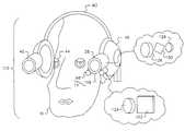
- the systemincludes a display screen 14 that is viewed by an observer 16 that is seated in a chair 18 .
- the chair 18is rotatably mounted onto a base 20 so that the chair 18 can be rotated for adjusting the viewing by the observer 16 .
- the system 10includes an imaging system 22 for projecting an image onto display screen 14 .
- the imaging system 22includes a computer 21 and digital imaging source 24 for obtaining digital images.
- the computer 21is used for controlling the appropriated components in the system 22 and for providing or receiving information from other system and/or components in system 10 .
- the image sourceis a Digital Video Disc (DVD) player which produces both a visual image signal but also an audio signal.
- DVDDigital Video Disc
- the imaging system 22further includes an illumination system 36 for illuminating the image from source 24 on to a lens assembly 60 .
- An optional infrared filter 30is provided to dissipate heat for safety reasons. Uniform, filtered illumination emerging from the lens assembly 28 is then incident on an input face 32 of a fiberoptic bundle 34 .
- the imaging system 22includes a pair of spaced image projectors 38 , 40 for displaying of an image on screen 14 .
- the projectors 38 , 40are mounted on head rest 42 that secured to chair 18 .
- the projectorsare mounted closely adjacent the eyes 44 of observer 16 such that the images projected from projectors 38 , 40 will reflect off screen 14 on to eyes 44 as discussed in detail later herein.
- the image signals from imaging source 24are transmitted to projectors 38 , 40 by fiber bundle 34 .
- the audio portions associated with the imagesare also transmitted to appropriate audio transducers such as speakers/headphones 46 . It is to be understood that the audio may be delivered using any conventional monaural, stereo, or surround-sound techniques well-known in the audio art.
- FIG. 1shows the light source 36 attached to the chair 18 an adequate distance from the ears of the observer 16 to insure that their operation will not interfere with the sound accompanying the display and to keep excess heat away from the observer's head 16 .
- Fiberoptic bundle 34carries light from the illumination system 36 to projectors 38 , 40 .
- the output end 52 of fiberoptic bundle 34transmits the image to the light valve arrays 54 .
- Suitable light valve array devices 54for the purposes of the invention include but are not limited to so-called microdisplays of the following types: transmissive liquid crystal displays, reflective liquid crystal displays, liquid crystal on silicon devices, deformable micro-mirror devices, grating light valve devices and the like. It is understood that required polarization elements, for example, polarizer 56 and analyzer 58 or other elements appropriate for each light valve option are included.
- the spatially modulated light from the light valvesthen enters lens assembly 60 in each projector 38 , 40 .
- Lens assembly 60projects an image beam 82 (FIG. 7) onto the modified retro-reflective screen 14 .
- Retro-reflectionis a concept familiar to those skilled in the art of optics and pertains to the ability of certain surfaces to reflect rays of light largely back to their source. This is in comparison to standard diffuse reflecting surfaces which disperse light rays in all directions.
- a retro-reflecting surfaceWhen a retro-reflecting surface is illuminated by projecting an image onto it, the light is reflected largely back to the source thus presenting an observer near the source with a brighter image for a given illumination than a similar observer would see further away from the source or when such an observer shines light onto a standard diffuse reflecting material.
- Retroreflective screensallow a less powerful light source to be used to provide a sufficient level of illumination to an observer.
- retro-reflective screen surfaceis “cube-corner” screen material. While retro-reflective screen material (such as the glass beaded surface of projection screens or traffic signs) largely reflects light rays back to their source, “cube-corner” screen material reflects light rays almost entirely to their source. For image projection onto a cube-corner screen, the screen effectively forms an “image” of the exit pupil of the projection lens back onto the projection lens exit pupil.
- the light ray's exit path from the cube-corneris made to differ from the entrance path, causing the trajectory of the reflected returning rays to deviate from the conventional retro-reflective condition.
- a modified cube-corner screencomprising a plurality of such modified cube-corners
- light reflected from the modified screenno longer forms an “image” of the projector exit constrained to the immediate area of (and radially surrounding) the projection lens assembly 60 referred to above. Instead, the modified screen forms a reflected “image” of the image exiting the projector 38 , 40 to an area around the projection lens assembly 60 .
- the nature of the expanded area of reflectioncan be controlled by the deviation of cube-corner dihedral angles from 90 degrees.
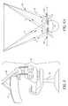
- the anglesare modified so the exiting light rays form a horizontally elongated “image” of the projector exit pupil in the plane of the projector lens exit pupil as best illustrated by reference to FIG. 3 B.
- the reflected image of a modified cube-cornerforms an elongated image area 70 (indicated by crosshatching in the illustration) centered on the projector lens assembly 60 as opposed to the generally circular reflective image area 72 of the standard cube-corner.
- the circular area of a prior art cube-corner display screenis not seen in a manner suitable for the observer, as the reflected image is reflected toward the associated projector.
- the projectors 38 , 40are positioned adjacent the head 48 of observer 16 so that a portion of the reflected image area 70 for each projector will cover the eye 44 of the observer 16 so that the observer can easily view the reflected image from the single adjacent projector.
- the present inventionavoids the need for the beamsplitters required in the prior art stereoscopic viewers.
- the horizontal elongation of the reflected beamprovides an advantage in that modest movements of the head of the observer 48 toward or away from the screen 14 do not result in the eye moving out from under the area of the reflected light beam. This results in a system that is tolerant of natural movement.
- a retro-reflecting screen modified to merely deflect the “image” of the projector exit pupil onto the position of the observer's eyewould result in a brighter image as viewed on the screen but would give up the tolerance to movement referred to above.
- FIG. 4 ashows an element from a conventional cube-corner retroreflective screen which provides a reflected image area illustrated by FIG. 4 b .
- FIG. 4cshows an element from a modified cube-corner retro-reflective screen made in accordance with the present invention which would be expected to provide the reflected image results illustrated in FIG. 4 d .
- U.S. Pat. No. 4,775,219teaches the preparation of tooling for the production of the type of modified cube-corner reflector element shown in FIG. 4 c.
- the element of FIG. 4 bdiffers from the conventional element of FIG. 4 a in that the angles a are wider than the 90 degree angles ⁇ of FIG. 4 a.
- the deviation of angles a from 90 degreescauses a deviation from true retroreflection such that the aforementioned horizontal elongation of the retroreflection of the “image” of the projector lens assembly 60 is achieved.
- FIG. 4 billustrates how a screen of conventional cube-corner retroreflective material 80 returns a projected light beam 82 substantially to the projection lens 38 , 40 .
- FIG. 4 dillustrates that images projected onto a screen 14 of modified retroreflective cube-corner screen material are reflected as sufficiently elongated image areas that cover the eye closest to each projector 38 , 40 without intersecting the other eye thus minimizing crosstalk of left and right images. Light from the modified retro-reflective screen 14 thus is returned by the screen directly to the eyes 44 of the observer 16 .
- the modified retro-reflective screen 14is mounted upon feet 84 (FIG. 1) to allow it to stand upright and be easily movable.
- the screenmay be mounted in any desired manner, for example but not by way of limitation the screen 14 may be hung from a boom 86 attached to the chair 18 as shown in FIG. 5, hanging the screen on a wall, from a ceiling or free-standing structure, or adhered to a surface or a wall.
- the cube-corner materialhas been modified to horizontally elongate the reflected image area.
- the projectors 38 , 40are positioned horizontally adjacent the eyes 44 of the observer 16 . Therefore as the shape of the cube-corner elements is modified, the projections will be appropriately positioned with respect to the eyes 44 of the observer 16 .
- the projectors 38 , 40are preferably located a short distance D away from each respective eye.
- the distance Dis chosen to provide the best combination of observer comfort and image brightness.
- the left/right crosstalki.e. light from the left projector 38 entering the right eye and the light from the right projector 40 entering the left eye is kept small as illustrated in FIGS. 6 b and 6 d. This prevents the appearance of undesirable ghost images.
- crosstalkcan be controlled by the positions of the projector 38 , 40 with respect to the adjacent eye. At large lateral distances D, little light will fall upon the eyes 44 of the observer 16 . Moving the projectors 38 , 40 larger distance D demands higher distortion of retro-reflecting elements to spread light of the exit pupil “image” over a larger area.
- the forward/backward positioning of projectors 38 , 40is preferably such that the forward end 90 is positioned at a plane P coincident with the observer's face 92 ′ as illustrated in FIG. 6 a. If the forward end 90 of projectors 38 , 40 are positioned a distance DP backward from plane P as illustrated in FIG. 6 c. then projected light may be occluded by the head of the observer 16 creating an occluded area OA. In addition, backward placement required additional elongation of the projected image to compensate for the natural reduction of image that results from having the projector back from plane P, as illustrated in 6 e. If the projectors 38 , 40 are positioned substantially forward of plane P as illustrated in FIG. 6 b, the projectors 38 , 40 may occlude the peripheral field of view of the observer 16 as well as creating a situation where each eye sees some portion of both the left and right image, creating an area of image crosstalk AC as previously described.
- FIGS. 1-4two separate projectors 38 , 40 are provided for images to be viewed by each of the respective eyes.
- a illumination schememay be provided by using a single illumination system and a beamsplitter to feed the left and right fiberoptic bundles.
- single illumination system and a bifurcated fiberoptic bundlemay be provided to split the illumination light into left and right portions.
- Full color imagesmay be produced by the display in FIG. 1 by any of the suitable techniques well known in the art. Such techniques include sequential color projection with alternating red/green/blue LEDs, illumination by the use of an interposed color wheel or DigiLens (TM), a switchable color filter element (see U.S. Pat. No. 5,825,448), separate RGB light valve arrays and beam-combining optics, or a single array with an integral color filters, and the like.
- TMinterposed color wheel or DigiLens
- the image projectors 38 , 40 and audio speakers/headphones 46are attached to supports 92 that are attached to the headrest 42 that can be adjusted in height.
- the supports 92are preferably attached so that they can be pivoted to allow the image projectors 38 , 40 to be moved wider apart to allow the observer 16 to easily sit down or get up from the chair 18 . Pivoting the supports 92 allow them to be moved out of the way by moving them up or down is an alternative that could be used.
- the supports 92can be brought in closer to the head to allow the closest comfortable position to the sides of the head when the observer 16 is seated. Any commonly available type or construction of headrest height adjustment that securely holds the headrest 42 and the projectors 38 , 40 is suitable.
- the image projectors 38 , 40 and audio transducers 46are mounted on supports 92 in such a fashion that allows them to be adjusted for horizontal proximity to the head of the chair's occupant. This is done to allow proper positioning of the projector's output upon the left and right eyes.
- the projectors 38 , 40are mounted on the arms so they can freely pivot in response to adjustments of the chair 18 (such as seatback rake) that would otherwise move the projected light vertically off the screen in a way that a portion of the top or bottom of the screen would be left unilluminated.
- the projectors 38 , 40are autofocusing and can employ any suitable technique familiar to one skilled in the art of projection and common on still and motion cameras.
- Position tracking techniques for projector 38 , 40 orientation sensinginclude: inertial systems using accelerometers and gyros, ambient systems using magnetometers, tilt sensors; optical fiducial tracking systems, electromagnetic tracking and the like.
- a well suited position and orientation tracking subsystem for the chair 18 of the embodiment of FIG. 1 of the present inventionincludes a rotational position encoding device 96 mounted to measure rotation of the chair 18 about a pivoting axis. Any suitable commercially available rotational position encoders can be used.
- This position informationis used to control and modify the source imagery being sent to the projectors 38 , 40 such that moving the projectors 38 , 40 causes shifting of the source image to compensate for physical shifting of the projected image with respect to screen 14 caused by movement of the projectors 38 , 40 .
- the rotational positional informationis forwarded to a computer 21 that is used for modifying the output of imaging source 24 .
- the result of the sensing and compensationis to fix still objects in the scene to an unmoving spot on the screen 14 . A distortion of the projected image will occur if the projector optical axes deviate from being perpendicular to the screen 14 .
- Such distortioncan be optionally compensated for by predistorting the source imagery in a manner that is cancelled in projection. Keystone compensation for side-to-side rotation is unnecessary if a screen 106 having a cylindrical geometry is used as shown in FIG. 7 .
- the projectorsare gimbaled so that the optical axes of the projectors are always substantially in the same position for forward and backward tilting of the chair.
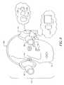
- FIG. 8there is illustrated a modified form of the present invention which incorporates a head-mounted projection system 110 which includes an image stabilization system wherein like numerals indicate like parts and operation as previously discussed
- the system 110comprises a an adjustable headband 112 that is worn by observer 16 .
- Imaging projectors 38 , 40 and audio transducers 46such as speakers or headphones are attached to the adjustable headband 112 .
- Any commonly available form of adjustable headband that securely holds the projection apparatusis suitable. Imaging projector locations are determined by considerations similar to the analogous discussion already given above for the chair-mounted embodiment of the invention. Since in the present embodiment, projectors 38 , 40 are worn on the head, there is no additional comfort afforded by moving the projectors laterally outward.
- the projectors 38 , 40are preferably located in close proximity to the head of the observer.
- an optical position-sensing subsystem 114comprising ultraviolet (UV) source 116 , and UV camera module 118 , provides information on the spatial relationship of the headband mounted projectors 38 , 40 to the modified retro-reflective screen 14 which has painted upon its surface fiducial marks 120 that are illuminated by UV source 116 and thus seen by the UV camera 118 whose output is sent to computer 21 for conversion into positional information that is then used to modify the output image in order to maintain a fixed image in a fixed position.
- UVultraviolet
- FIG. 9shows an example of fiducial marks 120 that have been added to the modified retroreflective screen 14 .
- the fiducial marks 120 of ultraviolet absorbing materialwhich are invisible to the human eye, are applied to the screen 14 surface by any appropriate technique, for example but not limited to, screen printing, stenciling, web-printing, and the like.
- a sensing subsystems 114senses the fiducial marks 120 to extract information regarding the position and orientation of the projectors 38 , 40 relative to the screen 14 .
- the system 114includes ultraviolet sensitive camera module 118 and ultraviolet source 116 . Under illumination from an ultraviolet source 116 the marks 120 (FIG. 18) appear as dark shapes..
- ultraviolet source 116is a UV light emitting diode.
- the camera module 118preferably comprises a CMOS or CCD sensor array 122 and an objective lens 124 and appropriate circuitry.
- the ultraviolet marks 120change position in the visual field of the camera module 118 .
- the fiducial image informationis used to determine the orientation of projectors 38 , 40 .
- Source imageryis then shifted such that fixed objects in the scene remain projected at fixed positions in space and so appear fixed in the reference frame of the screen. Such motion compensation is similar to that used for viewing of virtual worlds in head-mounted displays, with computer generated imagery.
- the source imagery provided to the projectors 38 , 40requires source data that provides a fill field of view, a full field being a source field of view larger than the instantaneously available field of view which is limited by the head-mounted projectors of the invention.
- modifications to source imagerycan include predistortion to compensate for possible keystone distortion as discussed previously.
- Optical image stabilization techniquesfor example, as disclosed in U.S. Pat. Nos. 5,243,462 or 5,315,435 assigned to Canon, may be employed to assist in the compensation of head-mounted projector movement.
- the projectors 38 , 40comprise conventional microdisplays (e.g. as disclosed in U.S. Pat. No. 5,748,164 to Displaytech and U.S. Pat. No. 5,528,397 to Kopin), lens assemblies 126 , and circuitry for video and audio(not shown).
- light sources 128 typically supplied with microdisplay light valves 130are replaced with brighter sources, for example higher power LEDs.
- Both reflective and transmissive microdisplay device typesare useful for the purposes of the invention. It is the very high gain of the modified cube-corner system that allows the relatively low optical power microdisplay devices to be useful.
- Lens assemblies 126project spatially modulated light from the microdisplay devices onto the modified cube-corner retro-reflector screen 14 as with the chair-mounted embodiment of FIG. 1 as described above.
- Power to projectors 38 , 40may be provided by batteries or from a remote supply may be carried by wire to the projectors 38 , 40 .
- informationis preferably input to the projectors by means of a high bandwidth RF (radio frequency) wireless connection such as disclosed in commonly assigned U.S. patent applications Ser. Nos. 09/089,204; 09/392,881; 09/519,199; and 09/575,597.
- RFradio frequency
- Other possible forms of connectioninclude wires and IR (infrared).
- the audio and image signalsare brought to audio and video circuitry for processing.
- the processed signalsare channeled to the appropriate left and right audio speakers/headphones 46 and left and right micro-displays light valves 130 .
- the spatially modulated light from micro-displays 130is projected as left and right images via a modified retro-reflective surface into the respective left and right eyes of the observer.
- the modified cube-corner retro-reflective screen 14forms horizontally elongated reflected images from the projectors 38 , 40 , a portion of each intersecting the respective eyes 44 of the observer 16 .
- the projectors 38 , 40are attached to the headband 112 an adequate distance from the eyes of wearer to insure that the reflected projection will fall upon the eye closest to the associated projector.
- the projectors 38 , 40optionally comprise subsystems for achieving autofocusing using suitable techniques familiar to the art and well known on still and motion cameras.
- the autofocusingis achieved by gauging the distance from the observer 16 to the screen 14 by measuring the change of scaling of the pattern of fiducial marks 120 .
- Full color imagesmay also be produced by any of the techniques well known to the art and already described above for the chair-mounted embodiment.
- FIG. 10illustrates how a spherical screen 108 can be used to allow wider ranges of free movement to an observer 16 .
- the screen(s)can also be mounted in a variety of planes, used as tabletops, upright windows, canted, or mounted like a ceiling.
- Systems analogous to that depicted in FIG. 10could be envisioned for the chair-mounted embodiment of FIG. 1 in a form ranging from a full spherical screen with a transparent plane used as a floor or with the chair positioned in the center of smaller subsections of a spherical screen.
Landscapes
- Physics & Mathematics (AREA)
- General Physics & Mathematics (AREA)
- Optics & Photonics (AREA)
- Testing, Inspecting, Measuring Of Stereoscopic Televisions And Televisions (AREA)
- Stereoscopic And Panoramic Photography (AREA)
- Projection Apparatus (AREA)
Abstract
Description
Claims (14)
Priority Applications (3)
| Application Number | Priority Date | Filing Date | Title |
|---|---|---|---|
| US09/730,360US6543899B2 (en) | 2000-12-05 | 2000-12-05 | Auto-stereoscopic viewing system using mounted projection |
| EP01204487AEP1213597A3 (en) | 2000-12-05 | 2001-11-23 | An auto-stereoscopic viewing system using head mounted projection |
| JP2001371407AJP2002250896A (en) | 2000-12-05 | 2001-12-05 | Automatic stereoscopic image projection system and stereoscopic image projection method |
Applications Claiming Priority (1)
| Application Number | Priority Date | Filing Date | Title |
|---|---|---|---|
| US09/730,360US6543899B2 (en) | 2000-12-05 | 2000-12-05 | Auto-stereoscopic viewing system using mounted projection |
Publications (2)
| Publication Number | Publication Date |
|---|---|
| US20020067466A1 US20020067466A1 (en) | 2002-06-06 |
| US6543899B2true US6543899B2 (en) | 2003-04-08 |
Family
ID=24935012
Family Applications (1)
| Application Number | Title | Priority Date | Filing Date |
|---|---|---|---|
| US09/730,360Expired - LifetimeUS6543899B2 (en) | 2000-12-05 | 2000-12-05 | Auto-stereoscopic viewing system using mounted projection |
Country Status (3)
| Country | Link |
|---|---|
| US (1) | US6543899B2 (en) |
| EP (1) | EP1213597A3 (en) |
| JP (1) | JP2002250896A (en) |
Cited By (88)
| Publication number | Priority date | Publication date | Assignee | Title |
|---|---|---|---|---|
| US20020087296A1 (en)* | 2001-01-03 | 2002-07-04 | Wynn Owen John Williams | Simulator |
| US20020130956A1 (en)* | 1995-11-06 | 2002-09-19 | Ricoh Company, Ltd. | Digital still video camera, image data output system for digital still video camera, frame for data relay for digital still video camera, data transfer system for digital still video camera, and image regenerating apparatus |
| US20040041929A1 (en)* | 2002-09-03 | 2004-03-04 | Marie Lapalme | Headset for camera |
| US6761459B1 (en)* | 1999-07-08 | 2004-07-13 | Svyatoslav Ivanovich Arsenich | Projection system |
| US20040162637A1 (en)* | 2002-07-25 | 2004-08-19 | Yulun Wang | Medical tele-robotic system with a master remote station with an arbitrator |
| US20040174129A1 (en)* | 2003-03-06 | 2004-09-09 | Yulun Wang | Medical tele-robotic system with a head worn device |
| US20050125098A1 (en)* | 2003-12-09 | 2005-06-09 | Yulun Wang | Protocol for a remotely controlled videoconferencing robot |
| US20060082642A1 (en)* | 2002-07-25 | 2006-04-20 | Yulun Wang | Tele-robotic videoconferencing in a corporate environment |
| US20060119539A1 (en)* | 2002-12-24 | 2006-06-08 | Nikon Corporation | Head mounted display |
| US7119965B1 (en)* | 2003-02-24 | 2006-10-10 | University Of Central Florida Research Foundation, Inc. | Head mounted projection display with a wide field of view |
| US20060259193A1 (en)* | 2005-05-12 | 2006-11-16 | Yulun Wang | Telerobotic system with a dual application screen presentation |
| US7158861B2 (en) | 2002-07-25 | 2007-01-02 | Intouch Technologies, Inc. | Tele-robotic system used to provide remote consultation services |
| US20070198130A1 (en)* | 2006-02-22 | 2007-08-23 | Yulun Wang | Graphical interface for a remote presence system |
| US20070291109A1 (en)* | 2006-06-15 | 2007-12-20 | Yulun Wang | Remote controlled mobile robot with auxillary input ports |
| US20080082211A1 (en)* | 2006-10-03 | 2008-04-03 | Yulun Wang | Remote presence display through remotely controlled robot |
| US20090055023A1 (en)* | 2007-08-23 | 2009-02-26 | Derek Walters | Telepresence robot with a printer |
| US20100014053A1 (en)* | 2008-07-21 | 2010-01-21 | Disney Enterprises, Inc. | Autostereoscopic projection system |
| US20100019715A1 (en)* | 2008-04-17 | 2010-01-28 | David Bjorn Roe | Mobile tele-presence system with a microphone system |
| US20100100240A1 (en)* | 2008-10-21 | 2010-04-22 | Yulun Wang | Telepresence robot with a camera boom |
| US20100131103A1 (en)* | 2008-11-25 | 2010-05-27 | Intouch Technologies, Inc. | Server connectivity control for tele-presence robot |
| US20100253916A1 (en)* | 2009-04-03 | 2010-10-07 | Chunyu Gao | Retro-Reflective Light Diffusing Display Systems |
| US20100253917A1 (en)* | 2009-04-03 | 2010-10-07 | Chunyu Gao | Aerial Three-Dimensional Image Display Systems |
| US20100253915A1 (en)* | 2009-04-03 | 2010-10-07 | Chunyu Gao | Retro-Reflective Light Diffusing Display Systems |
| US20100268383A1 (en)* | 2009-04-17 | 2010-10-21 | Yulun Wang | Tele-presence robot system with software modularity, projector and laser pointer |
| US20110199679A1 (en)* | 2010-02-15 | 2011-08-18 | Nelson Webb T | Stereoscopic Illumination System for Retroreflective Materials |
| US8077963B2 (en) | 2004-07-13 | 2011-12-13 | Yulun Wang | Mobile robot with a head-based movement mapping scheme |
| US20120002828A1 (en)* | 2010-06-30 | 2012-01-05 | Sony Corporation | Audio processing device, audio processing method, and program |
| US8179418B2 (en) | 2008-04-14 | 2012-05-15 | Intouch Technologies, Inc. | Robotic based health care system |
| USD660902S1 (en) | 2012-02-02 | 2012-05-29 | Hasbro, Inc. | Vision apparatus |
| WO2012149623A1 (en)* | 2011-05-04 | 2012-11-08 | Campbell Scott Andrew | Methods and apparatus for producing and capturing three dimensional images |
| US8340819B2 (en) | 2008-09-18 | 2012-12-25 | Intouch Technologies, Inc. | Mobile videoconferencing robot system with network adaptive driving |
| US8384755B2 (en) | 2009-08-26 | 2013-02-26 | Intouch Technologies, Inc. | Portable remote presence robot |
| US8670017B2 (en) | 2010-03-04 | 2014-03-11 | Intouch Technologies, Inc. | Remote presence system including a cart that supports a robot face and an overhead camera |
| US8718837B2 (en) | 2011-01-28 | 2014-05-06 | Intouch Technologies | Interfacing with a mobile telepresence robot |
| US8746914B2 (en) | 2010-02-15 | 2014-06-10 | Webb T. Nelson | Sports set that utilize stereoscopic illumination and retroreflective materials |
| US8836751B2 (en) | 2011-11-08 | 2014-09-16 | Intouch Technologies, Inc. | Tele-presence system with a user interface that displays different communication links |
| US8849679B2 (en) | 2006-06-15 | 2014-09-30 | Intouch Technologies, Inc. | Remote controlled robot system that provides medical images |
| US8849680B2 (en) | 2009-01-29 | 2014-09-30 | Intouch Technologies, Inc. | Documentation through a remote presence robot |
| US8892260B2 (en) | 2007-03-20 | 2014-11-18 | Irobot Corporation | Mobile robot for telecommunication |
| US8902278B2 (en) | 2012-04-11 | 2014-12-02 | Intouch Technologies, Inc. | Systems and methods for visualizing and managing telepresence devices in healthcare networks |
| US8930019B2 (en) | 2010-12-30 | 2015-01-06 | Irobot Corporation | Mobile human interface robot |
| US8935005B2 (en) | 2010-05-20 | 2015-01-13 | Irobot Corporation | Operating a mobile robot |
| US9014848B2 (en) | 2010-05-20 | 2015-04-21 | Irobot Corporation | Mobile robot system |
| US9098611B2 (en) | 2012-11-26 | 2015-08-04 | Intouch Technologies, Inc. | Enhanced video interaction for a user interface of a telepresence network |
| US9138891B2 (en) | 2008-11-25 | 2015-09-22 | Intouch Technologies, Inc. | Server connectivity control for tele-presence robot |
| US9160783B2 (en) | 2007-05-09 | 2015-10-13 | Intouch Technologies, Inc. | Robot system that operates through a network firewall |
| US9174342B2 (en) | 2012-05-22 | 2015-11-03 | Intouch Technologies, Inc. | Social behavior rules for a medical telepresence robot |
| US9193065B2 (en) | 2008-07-10 | 2015-11-24 | Intouch Technologies, Inc. | Docking system for a tele-presence robot |
| US9198728B2 (en) | 2005-09-30 | 2015-12-01 | Intouch Technologies, Inc. | Multi-camera mobile teleconferencing platform |
| US9251313B2 (en) | 2012-04-11 | 2016-02-02 | Intouch Technologies, Inc. | Systems and methods for visualizing and managing telepresence devices in healthcare networks |
| US9264664B2 (en) | 2010-12-03 | 2016-02-16 | Intouch Technologies, Inc. | Systems and methods for dynamic bandwidth allocation |
| US9323250B2 (en) | 2011-01-28 | 2016-04-26 | Intouch Technologies, Inc. | Time-dependent navigation of telepresence robots |
| US9361021B2 (en) | 2012-05-22 | 2016-06-07 | Irobot Corporation | Graphical user interfaces including touchpad driving interfaces for telemedicine devices |
| US9498886B2 (en) | 2010-05-20 | 2016-11-22 | Irobot Corporation | Mobile human interface robot |
| US9610685B2 (en) | 2004-02-26 | 2017-04-04 | Intouch Technologies, Inc. | Graphical interface for a remote presence system |
| US9842192B2 (en) | 2008-07-11 | 2017-12-12 | Intouch Technologies, Inc. | Tele-presence robot system with multi-cast features |
| US9974612B2 (en) | 2011-05-19 | 2018-05-22 | Intouch Technologies, Inc. | Enhanced diagnostics for a telepresence robot |
| US20180364355A1 (en)* | 2016-10-31 | 2018-12-20 | Gerard Dirk Smits | Fast scanning lidar with dynamic voxel probing |
| US10343283B2 (en) | 2010-05-24 | 2019-07-09 | Intouch Technologies, Inc. | Telepresence robot system that can be accessed by a cellular phone |
| US10477149B2 (en) | 2016-01-20 | 2019-11-12 | Gerard Dirk Smits | Holographic video capture and telepresence system |
| US10473921B2 (en) | 2017-05-10 | 2019-11-12 | Gerard Dirk Smits | Scan mirror systems and methods |
| US10502815B2 (en) | 2015-12-18 | 2019-12-10 | Gerard Dirk Smits | Real time position sensing of objects |
| US10564284B2 (en) | 2016-12-27 | 2020-02-18 | Gerard Dirk Smits | Systems and methods for machine perception |
| US10591605B2 (en) | 2017-10-19 | 2020-03-17 | Gerard Dirk Smits | Methods and systems for navigating a vehicle including a novel fiducial marker system |
| US10725177B2 (en) | 2018-01-29 | 2020-07-28 | Gerard Dirk Smits | Hyper-resolved, high bandwidth scanned LIDAR systems |
| US10769739B2 (en) | 2011-04-25 | 2020-09-08 | Intouch Technologies, Inc. | Systems and methods for management of information among medical providers and facilities |
| US10808882B2 (en) | 2010-05-26 | 2020-10-20 | Intouch Technologies, Inc. | Tele-robotic system with a robot face placed on a chair |
| US10875182B2 (en) | 2008-03-20 | 2020-12-29 | Teladoc Health, Inc. | Remote presence system mounted to operating room hardware |
| US10962867B2 (en) | 2007-10-10 | 2021-03-30 | Gerard Dirk Smits | Method, apparatus, and manufacture for a tracking camera or detector with fast asynchronous triggering |
| US11137497B2 (en) | 2014-08-11 | 2021-10-05 | Gerard Dirk Smits | Three-dimensional triangulation and time-of-flight based tracking systems and methods |
| US11154981B2 (en) | 2010-02-04 | 2021-10-26 | Teladoc Health, Inc. | Robot user interface for telepresence robot system |
| US11389064B2 (en) | 2018-04-27 | 2022-07-19 | Teladoc Health, Inc. | Telehealth cart that supports a removable tablet with seamless audio/video switching |
| US11399153B2 (en) | 2009-08-26 | 2022-07-26 | Teladoc Health, Inc. | Portable telepresence apparatus |
| US11636944B2 (en) | 2017-08-25 | 2023-04-25 | Teladoc Health, Inc. | Connectivity infrastructure for a telehealth platform |
| US11742094B2 (en) | 2017-07-25 | 2023-08-29 | Teladoc Health, Inc. | Modular telehealth cart with thermal imaging and touch screen user interface |
| US20230274462A1 (en)* | 2022-02-28 | 2023-08-31 | Basis Software, Inc. | System and method for camera calibration |
| US11829059B2 (en) | 2020-02-27 | 2023-11-28 | Gerard Dirk Smits | High resolution scanning of remote objects with fast sweeping laser beams and signal recovery by twitchy pixel array |
| US20230394707A1 (en)* | 2022-06-01 | 2023-12-07 | Proprio, Inc. | Methods and systems for calibrating and/or verifying a calibration of an imaging system such as a surgical imaging system |
| US11862302B2 (en) | 2017-04-24 | 2024-01-02 | Teladoc Health, Inc. | Automated transcription and documentation of tele-health encounters |
| US20240146900A1 (en)* | 2021-03-04 | 2024-05-02 | Rail Vision Ltd | System and method for verifying a selection of an optical sensor |
| US12025807B2 (en) | 2010-10-04 | 2024-07-02 | Gerard Dirk Smits | System and method for 3-D projection and enhancements for interactivity |
| US12093036B2 (en) | 2011-01-21 | 2024-09-17 | Teladoc Health, Inc. | Telerobotic system with a dual application screen presentation |
| US12224059B2 (en) | 2011-02-16 | 2025-02-11 | Teladoc Health, Inc. | Systems and methods for network-based counseling |
| US12244974B1 (en)* | 2022-01-11 | 2025-03-04 | Noah Buffett-Kennedy | Vehicular projection system |
| US20250142029A1 (en)* | 2023-10-31 | 2025-05-01 | Universal City Studios Llc | Systems and methods for projection mapping onto multiple rigid bodies |
| US12293548B2 (en)* | 2023-04-21 | 2025-05-06 | Toyota Research Institute, Inc. | Systems and methods for estimating scaled maps by sampling representations from a learning model |
| US20250172812A1 (en)* | 2010-10-04 | 2025-05-29 | Gerard Dirk Smits | System and method for 3-d projection and enhancements for interactivity |
| US12418623B2 (en)* | 2023-02-09 | 2025-09-16 | Samsung Display Co., Ltd. | Method of inspecting image quality, image quality inspection system performing the same, and display device to which the same is applied |
Families Citing this family (26)
| Publication number | Priority date | Publication date | Assignee | Title |
|---|---|---|---|---|
| US7018573B2 (en)* | 2002-10-08 | 2006-03-28 | Eastman Kodak Company | Method for making a modified cube corner retro-reflective screen |
| DE102005047712A1 (en)* | 2005-09-27 | 2007-03-29 | X3D Technologies Gmbh | Autostereoscopic arrangement for use in passenger car, has autostereoscopic display with control electronics for inspecting viewer located on seat, and determination unit for determining head position of viewer based on position of seat |
| US20100195201A1 (en)* | 2007-09-25 | 2010-08-05 | Kiyoshi Minoura | Screen |
| KR101498024B1 (en)* | 2008-01-22 | 2015-03-03 | 엘지전자 주식회사 | Projector and Its Image Distortion Correction Method |
| SG182336A1 (en)* | 2010-01-06 | 2012-08-30 | Applied Materials Inc | Flowable dielectric using oxide liner |
| US8573783B2 (en) | 2010-03-01 | 2013-11-05 | Gerard Dirk Smits | Safety device for scanned projector and illumination systems |
| US9298070B2 (en)* | 2010-04-29 | 2016-03-29 | Hewlett-Packard Development Company, L.P. | Participant collaboration on a displayed version of an object |
| WO2012000164A1 (en)* | 2010-06-28 | 2012-01-05 | Industrial Technology Research Institute | Projection auto-stereoscopic display and stereo screen |
| US8784206B1 (en) | 2011-04-15 | 2014-07-22 | Wms Gaming, Inc. | Modifying presentation of three-dimensional, wagering-game content |
| RU2510061C2 (en)* | 2011-05-11 | 2014-03-20 | Учреждение Российской академии наук Физический институт им. П.Н. Лебедева РАН (ФИАН) | Display for adaptive formation of three-dimensional images |
| CN102508651B (en)* | 2011-09-29 | 2015-04-15 | 深圳超多维光电子有限公司 | Realization method and system of user interface as well as electronic equipment |
| US8958599B1 (en)* | 2012-01-06 | 2015-02-17 | Google Inc. | Input method and system based on ambient glints |
| US9244339B2 (en) | 2012-06-15 | 2016-01-26 | Mirraviz, Inc. | Systems and methods for displaying an image or video on a retro-reflective screen |
| US8711370B1 (en) | 2012-10-04 | 2014-04-29 | Gerard Dirk Smits | Scanning optical positioning system with spatially triangulating receivers |
| US8971568B1 (en) | 2012-10-08 | 2015-03-03 | Gerard Dirk Smits | Method, apparatus, and manufacture for document writing and annotation with virtual ink |
| JP6121131B2 (en) | 2012-10-16 | 2017-04-26 | アルパイン株式会社 | Multiple display device |
| US20140119020A1 (en)* | 2012-10-30 | 2014-05-01 | Elwha Llc | Smart Illuminator For Retroreflective Display Device |
| US9810913B2 (en) | 2014-03-28 | 2017-11-07 | Gerard Dirk Smits | Smart head-mounted projection system |
| EP3149543A4 (en)* | 2014-05-27 | 2018-01-03 | Mirraviz Inc. | Methods for optimizing retro-reflective display systems |
| KR20160088211A (en)* | 2015-01-15 | 2016-07-25 | 최해용 | A large projection screen image device with seesaw structure for virtual reality |
| KR102627249B1 (en)* | 2015-01-21 | 2024-01-18 | 테세랜드 엘엘씨 | Display with total internal reflection |
| US10043282B2 (en) | 2015-04-13 | 2018-08-07 | Gerard Dirk Smits | Machine vision for ego-motion, segmenting, and classifying objects |
| WO2017095341A1 (en)* | 2015-12-04 | 2017-06-08 | Koc Universitesi | Physical object reconstruction through a projection display system |
| JP6855493B2 (en)* | 2016-02-23 | 2021-04-07 | ジェラルド ディルク スミッツ | Holographic video capture and telepresence system |
| WO2018027071A1 (en)* | 2016-08-03 | 2018-02-08 | Mirraviz, Inc. | Real time algorithmic calibration and compensation of virtual and augmented reality systems and optimized semi-transparent and transparent retroreflective display systems and methods |
| CN110568715A (en)* | 2019-09-30 | 2019-12-13 | 宁波元年文化传媒有限公司 | stereo sphere surface full-coverage projection device |
Citations (20)
| Publication number | Priority date | Publication date | Assignee | Title |
|---|---|---|---|---|
| US4347508A (en) | 1978-12-21 | 1982-08-31 | Redifon Simulation Limited | Visual display apparatus |
| US4439157A (en)* | 1982-05-03 | 1984-03-27 | The United States Of America As Represented By The Secretary Of The Navy | Helmet mounted display projector |
| US4775219A (en) | 1986-11-21 | 1988-10-04 | Minnesota Mining & Manufacturing Company | Cube-corner retroreflective articles having tailored divergence profiles |
| JPS6429830A (en)* | 1987-07-25 | 1989-01-31 | Sony Corp | Spectacles-less stereoscopic video projector |
| US5243462A (en) | 1989-04-28 | 1993-09-07 | Canon Kabushiki Kaisha | Image stabilizing apparatus |
| US5315435A (en) | 1990-05-16 | 1994-05-24 | Canon Kabushiki Kaisha | Image stabilizing optical system |
| US5418584A (en)* | 1992-12-31 | 1995-05-23 | Honeywell Inc. | Retroreflective array virtual image projection screen |
| US5528397A (en) | 1991-12-03 | 1996-06-18 | Kopin Corporation | Single crystal silicon transistors for display panels |
| US5606458A (en) | 1994-08-24 | 1997-02-25 | Fergason; James L. | Head mounted display and viewing system using a remote retro-reflector and method of displaying and viewing an image |
| US5671992A (en) | 1993-04-28 | 1997-09-30 | Xenotech Research Pty. Ltd. | Stereoscopic display unit |
| US5748164A (en) | 1994-12-22 | 1998-05-05 | Displaytech, Inc. | Active matrix liquid crystal image generator |
| US5825448A (en) | 1995-05-19 | 1998-10-20 | Kent State University | Reflective optically active diffractive device |
| US5976017A (en)* | 1994-02-09 | 1999-11-02 | Terumo Kabushiki Kaisha | Stereoscopic-image game playing apparatus |
| US6034717A (en)* | 1993-09-23 | 2000-03-07 | Reveo, Inc. | Projection display system for viewing displayed imagery over a wide field of view |
| US6069608A (en)* | 1996-12-03 | 2000-05-30 | Sony Corporation | Display device having perception image for improving depth perception of a virtual image |
| WO2000034818A1 (en) | 1998-12-07 | 2000-06-15 | Koninklijke Philips Electronics N.V. | Head-mounted projection display system |
| US6163336A (en)* | 1994-12-13 | 2000-12-19 | Richards; Angus Duncan | Tracking system for stereoscopic display systems |
| US6292305B1 (en)* | 1997-08-25 | 2001-09-18 | Ricoh Company, Ltd. | Virtual screen display device |
| US6323999B1 (en)* | 1999-08-04 | 2001-11-27 | Minolta Co., Ltd. | Image display apparatus |
| US6416181B1 (en)* | 2000-12-15 | 2002-07-09 | Eastman Kodak Company | Monocentric autostereoscopic optical apparatus and method |
- 2000
- 2000-12-05USUS09/730,360patent/US6543899B2/ennot_activeExpired - Lifetime
- 2001
- 2001-11-23EPEP01204487Apatent/EP1213597A3/ennot_activeWithdrawn
- 2001-12-05JPJP2001371407Apatent/JP2002250896A/enactivePending
Patent Citations (21)
| Publication number | Priority date | Publication date | Assignee | Title |
|---|---|---|---|---|
| US4347508A (en) | 1978-12-21 | 1982-08-31 | Redifon Simulation Limited | Visual display apparatus |
| US4439157A (en)* | 1982-05-03 | 1984-03-27 | The United States Of America As Represented By The Secretary Of The Navy | Helmet mounted display projector |
| US4775219A (en) | 1986-11-21 | 1988-10-04 | Minnesota Mining & Manufacturing Company | Cube-corner retroreflective articles having tailored divergence profiles |
| JPS6429830A (en)* | 1987-07-25 | 1989-01-31 | Sony Corp | Spectacles-less stereoscopic video projector |
| US5243462A (en) | 1989-04-28 | 1993-09-07 | Canon Kabushiki Kaisha | Image stabilizing apparatus |
| US5315435A (en) | 1990-05-16 | 1994-05-24 | Canon Kabushiki Kaisha | Image stabilizing optical system |
| US5528397A (en) | 1991-12-03 | 1996-06-18 | Kopin Corporation | Single crystal silicon transistors for display panels |
| US5418584A (en)* | 1992-12-31 | 1995-05-23 | Honeywell Inc. | Retroreflective array virtual image projection screen |
| US5671992A (en) | 1993-04-28 | 1997-09-30 | Xenotech Research Pty. Ltd. | Stereoscopic display unit |
| US6034717A (en)* | 1993-09-23 | 2000-03-07 | Reveo, Inc. | Projection display system for viewing displayed imagery over a wide field of view |
| US5976017A (en)* | 1994-02-09 | 1999-11-02 | Terumo Kabushiki Kaisha | Stereoscopic-image game playing apparatus |
| US5606458A (en) | 1994-08-24 | 1997-02-25 | Fergason; James L. | Head mounted display and viewing system using a remote retro-reflector and method of displaying and viewing an image |
| US6163336A (en)* | 1994-12-13 | 2000-12-19 | Richards; Angus Duncan | Tracking system for stereoscopic display systems |
| US5748164A (en) | 1994-12-22 | 1998-05-05 | Displaytech, Inc. | Active matrix liquid crystal image generator |
| US5825448A (en) | 1995-05-19 | 1998-10-20 | Kent State University | Reflective optically active diffractive device |
| US6069608A (en)* | 1996-12-03 | 2000-05-30 | Sony Corporation | Display device having perception image for improving depth perception of a virtual image |
| US6292305B1 (en)* | 1997-08-25 | 2001-09-18 | Ricoh Company, Ltd. | Virtual screen display device |
| WO2000034818A1 (en) | 1998-12-07 | 2000-06-15 | Koninklijke Philips Electronics N.V. | Head-mounted projection display system |
| US20010043165A1 (en)* | 1998-12-07 | 2001-11-22 | Philips Electronics North America Corporation | Head-mounted projection display system |
| US6323999B1 (en)* | 1999-08-04 | 2001-11-27 | Minolta Co., Ltd. | Image display apparatus |
| US6416181B1 (en)* | 2000-12-15 | 2002-07-09 | Eastman Kodak Company | Monocentric autostereoscopic optical apparatus and method |
Non-Patent Citations (2)
| Title |
|---|
| "Micropolarizer-based multiple-viewer autostereoscopic display" by Benton, Slowe, Kropp and Smith in J.O. Merritt, SS. Fisher, and M.T. Bolas, Eds., SPIE Proc. vol. 3639 Stereoscopic Displays and Virtual Reality Systems VI (SPIE, Jan. 1999) paper 3639-10, p. 1. |
| ACM SIGGRAPH 99 Conference Abstracts and Applications document, p. 179, "Head-Mounted Projector". |
Cited By (179)
| Publication number | Priority date | Publication date | Assignee | Title |
|---|---|---|---|---|
| US20020130956A1 (en)* | 1995-11-06 | 2002-09-19 | Ricoh Company, Ltd. | Digital still video camera, image data output system for digital still video camera, frame for data relay for digital still video camera, data transfer system for digital still video camera, and image regenerating apparatus |
| US6761459B1 (en)* | 1999-07-08 | 2004-07-13 | Svyatoslav Ivanovich Arsenich | Projection system |
| US7200536B2 (en)* | 2001-01-03 | 2007-04-03 | Seos Limited | Simulator |
| US20020087296A1 (en)* | 2001-01-03 | 2002-07-04 | Wynn Owen John Williams | Simulator |
| USRE45870E1 (en) | 2002-07-25 | 2016-01-26 | Intouch Technologies, Inc. | Apparatus and method for patient rounding with a remote controlled robot |
| US7158861B2 (en) | 2002-07-25 | 2007-01-02 | Intouch Technologies, Inc. | Tele-robotic system used to provide remote consultation services |
| US8209051B2 (en) | 2002-07-25 | 2012-06-26 | Intouch Technologies, Inc. | Medical tele-robotic system |
| US20060082642A1 (en)* | 2002-07-25 | 2006-04-20 | Yulun Wang | Tele-robotic videoconferencing in a corporate environment |
| US9849593B2 (en) | 2002-07-25 | 2017-12-26 | Intouch Technologies, Inc. | Medical tele-robotic system with a master remote station with an arbitrator |
| US7593030B2 (en) | 2002-07-25 | 2009-09-22 | Intouch Technologies, Inc. | Tele-robotic videoconferencing in a corporate environment |
| US20080029536A1 (en)* | 2002-07-25 | 2008-02-07 | Intouch Technologies, Inc. | Medical tele-robotic system |
| US10315312B2 (en) | 2002-07-25 | 2019-06-11 | Intouch Technologies, Inc. | Medical tele-robotic system with a master remote station with an arbitrator |
| US20070021871A1 (en)* | 2002-07-25 | 2007-01-25 | Yulun Wang | Medical tele-robotic system |
| US20040162637A1 (en)* | 2002-07-25 | 2004-08-19 | Yulun Wang | Medical tele-robotic system with a master remote station with an arbitrator |
| US7289883B2 (en) | 2002-07-25 | 2007-10-30 | Intouch Technologies, Inc. | Apparatus and method for patient rounding with a remote controlled robot |
| US20070112464A1 (en)* | 2002-07-25 | 2007-05-17 | Yulun Wang | Apparatus and method for patient rounding with a remote controlled robot |
| US8515577B2 (en) | 2002-07-25 | 2013-08-20 | Yulun Wang | Medical tele-robotic system with a master remote station with an arbitrator |
| US20080201017A1 (en)* | 2002-07-25 | 2008-08-21 | Yulun Wang | Medical tele-robotic system |
| US7209177B2 (en)* | 2002-09-03 | 2007-04-24 | Audisoft | Headset for camera |
| US20040041929A1 (en)* | 2002-09-03 | 2004-03-04 | Marie Lapalme | Headset for camera |
| US7542012B2 (en)* | 2002-12-24 | 2009-06-02 | Nikon Corporation | Head mounted display |
| US20090243970A1 (en)* | 2002-12-24 | 2009-10-01 | Nikon Corporation | Head mount display |
| US8400371B2 (en) | 2002-12-24 | 2013-03-19 | Nikon Corporation | Head mount display |
| US20060119539A1 (en)* | 2002-12-24 | 2006-06-08 | Nikon Corporation | Head mounted display |
| US7119965B1 (en)* | 2003-02-24 | 2006-10-10 | University Of Central Florida Research Foundation, Inc. | Head mounted projection display with a wide field of view |
| US7262573B2 (en)* | 2003-03-06 | 2007-08-28 | Intouch Technologies, Inc. | Medical tele-robotic system with a head worn device |
| US20040174129A1 (en)* | 2003-03-06 | 2004-09-09 | Yulun Wang | Medical tele-robotic system with a head worn device |
| US9375843B2 (en) | 2003-12-09 | 2016-06-28 | Intouch Technologies, Inc. | Protocol for a remotely controlled videoconferencing robot |
| US10882190B2 (en) | 2003-12-09 | 2021-01-05 | Teladoc Health, Inc. | Protocol for a remotely controlled videoconferencing robot |
| US9956690B2 (en) | 2003-12-09 | 2018-05-01 | Intouch Technologies, Inc. | Protocol for a remotely controlled videoconferencing robot |
| US20050125098A1 (en)* | 2003-12-09 | 2005-06-09 | Yulun Wang | Protocol for a remotely controlled videoconferencing robot |
| US7813836B2 (en) | 2003-12-09 | 2010-10-12 | Intouch Technologies, Inc. | Protocol for a remotely controlled videoconferencing robot |
| US9610685B2 (en) | 2004-02-26 | 2017-04-04 | Intouch Technologies, Inc. | Graphical interface for a remote presence system |
| US10241507B2 (en) | 2004-07-13 | 2019-03-26 | Intouch Technologies, Inc. | Mobile robot with a head-based movement mapping scheme |
| US9766624B2 (en) | 2004-07-13 | 2017-09-19 | Intouch Technologies, Inc. | Mobile robot with a head-based movement mapping scheme |
| US8983174B2 (en) | 2004-07-13 | 2015-03-17 | Intouch Technologies, Inc. | Mobile robot with a head-based movement mapping scheme |
| US8401275B2 (en) | 2004-07-13 | 2013-03-19 | Intouch Technologies, Inc. | Mobile robot with a head-based movement mapping scheme |
| US8077963B2 (en) | 2004-07-13 | 2011-12-13 | Yulun Wang | Mobile robot with a head-based movement mapping scheme |
| US20060259193A1 (en)* | 2005-05-12 | 2006-11-16 | Yulun Wang | Telerobotic system with a dual application screen presentation |
| US10259119B2 (en) | 2005-09-30 | 2019-04-16 | Intouch Technologies, Inc. | Multi-camera mobile teleconferencing platform |
| US9198728B2 (en) | 2005-09-30 | 2015-12-01 | Intouch Technologies, Inc. | Multi-camera mobile teleconferencing platform |
| US7769492B2 (en) | 2006-02-22 | 2010-08-03 | Intouch Technologies, Inc. | Graphical interface for a remote presence system |
| US20070198130A1 (en)* | 2006-02-22 | 2007-08-23 | Yulun Wang | Graphical interface for a remote presence system |
| US8849679B2 (en) | 2006-06-15 | 2014-09-30 | Intouch Technologies, Inc. | Remote controlled robot system that provides medical images |
| US20070291109A1 (en)* | 2006-06-15 | 2007-12-20 | Yulun Wang | Remote controlled mobile robot with auxillary input ports |
| US20080082211A1 (en)* | 2006-10-03 | 2008-04-03 | Yulun Wang | Remote presence display through remotely controlled robot |
| US7761185B2 (en) | 2006-10-03 | 2010-07-20 | Intouch Technologies, Inc. | Remote presence display through remotely controlled robot |
| US9296109B2 (en) | 2007-03-20 | 2016-03-29 | Irobot Corporation | Mobile robot for telecommunication |
| US8892260B2 (en) | 2007-03-20 | 2014-11-18 | Irobot Corporation | Mobile robot for telecommunication |
| US10682763B2 (en) | 2007-05-09 | 2020-06-16 | Intouch Technologies, Inc. | Robot system that operates through a network firewall |
| US9160783B2 (en) | 2007-05-09 | 2015-10-13 | Intouch Technologies, Inc. | Robot system that operates through a network firewall |
| US8116910B2 (en) | 2007-08-23 | 2012-02-14 | Intouch Technologies, Inc. | Telepresence robot with a printer |
| US20090055023A1 (en)* | 2007-08-23 | 2009-02-26 | Derek Walters | Telepresence robot with a printer |
| US10962867B2 (en) | 2007-10-10 | 2021-03-30 | Gerard Dirk Smits | Method, apparatus, and manufacture for a tracking camera or detector with fast asynchronous triggering |
| US11787060B2 (en) | 2008-03-20 | 2023-10-17 | Teladoc Health, Inc. | Remote presence system mounted to operating room hardware |
| US10875182B2 (en) | 2008-03-20 | 2020-12-29 | Teladoc Health, Inc. | Remote presence system mounted to operating room hardware |
| US11472021B2 (en) | 2008-04-14 | 2022-10-18 | Teladoc Health, Inc. | Robotic based health care system |
| US8179418B2 (en) | 2008-04-14 | 2012-05-15 | Intouch Technologies, Inc. | Robotic based health care system |
| US10471588B2 (en) | 2008-04-14 | 2019-11-12 | Intouch Technologies, Inc. | Robotic based health care system |
| US20100019715A1 (en)* | 2008-04-17 | 2010-01-28 | David Bjorn Roe | Mobile tele-presence system with a microphone system |
| US8170241B2 (en) | 2008-04-17 | 2012-05-01 | Intouch Technologies, Inc. | Mobile tele-presence system with a microphone system |
| US10493631B2 (en) | 2008-07-10 | 2019-12-03 | Intouch Technologies, Inc. | Docking system for a tele-presence robot |
| US9193065B2 (en) | 2008-07-10 | 2015-11-24 | Intouch Technologies, Inc. | Docking system for a tele-presence robot |
| US9842192B2 (en) | 2008-07-11 | 2017-12-12 | Intouch Technologies, Inc. | Tele-presence robot system with multi-cast features |
| US10878960B2 (en) | 2008-07-11 | 2020-12-29 | Teladoc Health, Inc. | Tele-presence robot system with multi-cast features |
| US20100014053A1 (en)* | 2008-07-21 | 2010-01-21 | Disney Enterprises, Inc. | Autostereoscopic projection system |
| US7938540B2 (en) | 2008-07-21 | 2011-05-10 | Disney Enterprises, Inc. | Autostereoscopic projection system |
| US9429934B2 (en) | 2008-09-18 | 2016-08-30 | Intouch Technologies, Inc. | Mobile videoconferencing robot system with network adaptive driving |
| US8340819B2 (en) | 2008-09-18 | 2012-12-25 | Intouch Technologies, Inc. | Mobile videoconferencing robot system with network adaptive driving |
| US20100100240A1 (en)* | 2008-10-21 | 2010-04-22 | Yulun Wang | Telepresence robot with a camera boom |
| US8996165B2 (en) | 2008-10-21 | 2015-03-31 | Intouch Technologies, Inc. | Telepresence robot with a camera boom |
| US8463435B2 (en) | 2008-11-25 | 2013-06-11 | Intouch Technologies, Inc. | Server connectivity control for tele-presence robot |
| US10875183B2 (en) | 2008-11-25 | 2020-12-29 | Teladoc Health, Inc. | Server connectivity control for tele-presence robot |
| US10059000B2 (en) | 2008-11-25 | 2018-08-28 | Intouch Technologies, Inc. | Server connectivity control for a tele-presence robot |
| US9138891B2 (en) | 2008-11-25 | 2015-09-22 | Intouch Technologies, Inc. | Server connectivity control for tele-presence robot |
| US20100131103A1 (en)* | 2008-11-25 | 2010-05-27 | Intouch Technologies, Inc. | Server connectivity control for tele-presence robot |
| US12138808B2 (en) | 2008-11-25 | 2024-11-12 | Teladoc Health, Inc. | Server connectivity control for tele-presence robots |
| US8849680B2 (en) | 2009-01-29 | 2014-09-30 | Intouch Technologies, Inc. | Documentation through a remote presence robot |
| US20100253917A1 (en)* | 2009-04-03 | 2010-10-07 | Chunyu Gao | Aerial Three-Dimensional Image Display Systems |
| US8328360B2 (en) | 2009-04-03 | 2012-12-11 | Seiko Epson Corporation | Retro-reflective light diffusing autostereoscopic 3D display systems |
| US20100253916A1 (en)* | 2009-04-03 | 2010-10-07 | Chunyu Gao | Retro-Reflective Light Diffusing Display Systems |
| US7993016B2 (en) | 2009-04-03 | 2011-08-09 | Seiko Epson Corporation | Retro-reflective light diffusing display systems |
| US8287127B2 (en) | 2009-04-03 | 2012-10-16 | Seiko Epson Corporation | Aerial three-dimensional image display systems |
| US20100253915A1 (en)* | 2009-04-03 | 2010-10-07 | Chunyu Gao | Retro-Reflective Light Diffusing Display Systems |
| US10969766B2 (en) | 2009-04-17 | 2021-04-06 | Teladoc Health, Inc. | Tele-presence robot system with software modularity, projector and laser pointer |
| US8897920B2 (en) | 2009-04-17 | 2014-11-25 | Intouch Technologies, Inc. | Tele-presence robot system with software modularity, projector and laser pointer |
| US20100268383A1 (en)* | 2009-04-17 | 2010-10-21 | Yulun Wang | Tele-presence robot system with software modularity, projector and laser pointer |
| US10404939B2 (en) | 2009-08-26 | 2019-09-03 | Intouch Technologies, Inc. | Portable remote presence robot |
| US9602765B2 (en) | 2009-08-26 | 2017-03-21 | Intouch Technologies, Inc. | Portable remote presence robot |
| US8384755B2 (en) | 2009-08-26 | 2013-02-26 | Intouch Technologies, Inc. | Portable remote presence robot |
| US10911715B2 (en) | 2009-08-26 | 2021-02-02 | Teladoc Health, Inc. | Portable remote presence robot |
| US11399153B2 (en) | 2009-08-26 | 2022-07-26 | Teladoc Health, Inc. | Portable telepresence apparatus |
| US11154981B2 (en) | 2010-02-04 | 2021-10-26 | Teladoc Health, Inc. | Robot user interface for telepresence robot system |
| US20110199679A1 (en)* | 2010-02-15 | 2011-08-18 | Nelson Webb T | Stereoscopic Illumination System for Retroreflective Materials |
| US8550649B2 (en) | 2010-02-15 | 2013-10-08 | Webb T. Nelson | Stereoscopic illumination system for retroreflective materials |
| US8746914B2 (en) | 2010-02-15 | 2014-06-10 | Webb T. Nelson | Sports set that utilize stereoscopic illumination and retroreflective materials |
| US11798683B2 (en) | 2010-03-04 | 2023-10-24 | Teladoc Health, Inc. | Remote presence system including a cart that supports a robot face and an overhead camera |
| US10887545B2 (en) | 2010-03-04 | 2021-01-05 | Teladoc Health, Inc. | Remote presence system including a cart that supports a robot face and an overhead camera |
| US8670017B2 (en) | 2010-03-04 | 2014-03-11 | Intouch Technologies, Inc. | Remote presence system including a cart that supports a robot face and an overhead camera |
| US9089972B2 (en) | 2010-03-04 | 2015-07-28 | Intouch Technologies, Inc. | Remote presence system including a cart that supports a robot face and an overhead camera |
| US9498886B2 (en) | 2010-05-20 | 2016-11-22 | Irobot Corporation | Mobile human interface robot |
| US9014848B2 (en) | 2010-05-20 | 2015-04-21 | Irobot Corporation | Mobile robot system |
| US9902069B2 (en) | 2010-05-20 | 2018-02-27 | Irobot Corporation | Mobile robot system |
| US8935005B2 (en) | 2010-05-20 | 2015-01-13 | Irobot Corporation | Operating a mobile robot |
| US10343283B2 (en) | 2010-05-24 | 2019-07-09 | Intouch Technologies, Inc. | Telepresence robot system that can be accessed by a cellular phone |
| US11389962B2 (en) | 2010-05-24 | 2022-07-19 | Teladoc Health, Inc. | Telepresence robot system that can be accessed by a cellular phone |
| US10808882B2 (en) | 2010-05-26 | 2020-10-20 | Intouch Technologies, Inc. | Tele-robotic system with a robot face placed on a chair |
| US9351092B2 (en)* | 2010-06-30 | 2016-05-24 | Sony Corporation | Audio processing device, audio processing method, and program |
| US20120002828A1 (en)* | 2010-06-30 | 2012-01-05 | Sony Corporation | Audio processing device, audio processing method, and program |
| US12025807B2 (en) | 2010-10-04 | 2024-07-02 | Gerard Dirk Smits | System and method for 3-D projection and enhancements for interactivity |
| US20250172812A1 (en)* | 2010-10-04 | 2025-05-29 | Gerard Dirk Smits | System and method for 3-d projection and enhancements for interactivity |
| US10218748B2 (en) | 2010-12-03 | 2019-02-26 | Intouch Technologies, Inc. | Systems and methods for dynamic bandwidth allocation |
| US9264664B2 (en) | 2010-12-03 | 2016-02-16 | Intouch Technologies, Inc. | Systems and methods for dynamic bandwidth allocation |
| US8930019B2 (en) | 2010-12-30 | 2015-01-06 | Irobot Corporation | Mobile human interface robot |
| US12093036B2 (en) | 2011-01-21 | 2024-09-17 | Teladoc Health, Inc. | Telerobotic system with a dual application screen presentation |
| US11289192B2 (en) | 2011-01-28 | 2022-03-29 | Intouch Technologies, Inc. | Interfacing with a mobile telepresence robot |
| US9785149B2 (en) | 2011-01-28 | 2017-10-10 | Intouch Technologies, Inc. | Time-dependent navigation of telepresence robots |
| US9323250B2 (en) | 2011-01-28 | 2016-04-26 | Intouch Technologies, Inc. | Time-dependent navigation of telepresence robots |
| US9469030B2 (en) | 2011-01-28 | 2016-10-18 | Intouch Technologies | Interfacing with a mobile telepresence robot |
| US11468983B2 (en) | 2011-01-28 | 2022-10-11 | Teladoc Health, Inc. | Time-dependent navigation of telepresence robots |
| US8965579B2 (en) | 2011-01-28 | 2015-02-24 | Intouch Technologies | Interfacing with a mobile telepresence robot |
| US10591921B2 (en) | 2011-01-28 | 2020-03-17 | Intouch Technologies, Inc. | Time-dependent navigation of telepresence robots |
| US8718837B2 (en) | 2011-01-28 | 2014-05-06 | Intouch Technologies | Interfacing with a mobile telepresence robot |
| US10399223B2 (en) | 2011-01-28 | 2019-09-03 | Intouch Technologies, Inc. | Interfacing with a mobile telepresence robot |
| US12224059B2 (en) | 2011-02-16 | 2025-02-11 | Teladoc Health, Inc. | Systems and methods for network-based counseling |
| US10769739B2 (en) | 2011-04-25 | 2020-09-08 | Intouch Technologies, Inc. | Systems and methods for management of information among medical providers and facilities |
| US9398285B2 (en) | 2011-05-04 | 2016-07-19 | Scott Andrew Campbell | Methods and apparatus for producing and capturing three dimensional images |
| WO2012149623A1 (en)* | 2011-05-04 | 2012-11-08 | Campbell Scott Andrew | Methods and apparatus for producing and capturing three dimensional images |
| US9974612B2 (en) | 2011-05-19 | 2018-05-22 | Intouch Technologies, Inc. | Enhanced diagnostics for a telepresence robot |
| US9715337B2 (en) | 2011-11-08 | 2017-07-25 | Intouch Technologies, Inc. | Tele-presence system with a user interface that displays different communication links |
| US10331323B2 (en) | 2011-11-08 | 2019-06-25 | Intouch Technologies, Inc. | Tele-presence system with a user interface that displays different communication links |
| US8836751B2 (en) | 2011-11-08 | 2014-09-16 | Intouch Technologies, Inc. | Tele-presence system with a user interface that displays different communication links |
| USD660902S1 (en) | 2012-02-02 | 2012-05-29 | Hasbro, Inc. | Vision apparatus |
| US9251313B2 (en) | 2012-04-11 | 2016-02-02 | Intouch Technologies, Inc. | Systems and methods for visualizing and managing telepresence devices in healthcare networks |
| US8902278B2 (en) | 2012-04-11 | 2014-12-02 | Intouch Technologies, Inc. | Systems and methods for visualizing and managing telepresence devices in healthcare networks |
| US11205510B2 (en) | 2012-04-11 | 2021-12-21 | Teladoc Health, Inc. | Systems and methods for visualizing and managing telepresence devices in healthcare networks |
| US10762170B2 (en) | 2012-04-11 | 2020-09-01 | Intouch Technologies, Inc. | Systems and methods for visualizing patient and telepresence device statistics in a healthcare network |
| US10892052B2 (en) | 2012-05-22 | 2021-01-12 | Intouch Technologies, Inc. | Graphical user interfaces including touchpad driving interfaces for telemedicine devices |
| US10328576B2 (en) | 2012-05-22 | 2019-06-25 | Intouch Technologies, Inc. | Social behavior rules for a medical telepresence robot |
| US9174342B2 (en) | 2012-05-22 | 2015-11-03 | Intouch Technologies, Inc. | Social behavior rules for a medical telepresence robot |
| US9361021B2 (en) | 2012-05-22 | 2016-06-07 | Irobot Corporation | Graphical user interfaces including touchpad driving interfaces for telemedicine devices |
| US9776327B2 (en) | 2012-05-22 | 2017-10-03 | Intouch Technologies, Inc. | Social behavior rules for a medical telepresence robot |
| US11628571B2 (en) | 2012-05-22 | 2023-04-18 | Teladoc Health, Inc. | Social behavior rules for a medical telepresence robot |
| US11515049B2 (en) | 2012-05-22 | 2022-11-29 | Teladoc Health, Inc. | Graphical user interfaces including touchpad driving interfaces for telemedicine devices |
| US10061896B2 (en) | 2012-05-22 | 2018-08-28 | Intouch Technologies, Inc. | Graphical user interfaces including touchpad driving interfaces for telemedicine devices |
| US11453126B2 (en) | 2012-05-22 | 2022-09-27 | Teladoc Health, Inc. | Clinical workflows utilizing autonomous and semi-autonomous telemedicine devices |
| US10603792B2 (en) | 2012-05-22 | 2020-03-31 | Intouch Technologies, Inc. | Clinical workflows utilizing autonomous and semiautonomous telemedicine devices |
| US10658083B2 (en) | 2012-05-22 | 2020-05-19 | Intouch Technologies, Inc. | Graphical user interfaces including touchpad driving interfaces for telemedicine devices |
| US10780582B2 (en) | 2012-05-22 | 2020-09-22 | Intouch Technologies, Inc. | Social behavior rules for a medical telepresence robot |
| US11910128B2 (en) | 2012-11-26 | 2024-02-20 | Teladoc Health, Inc. | Enhanced video interaction for a user interface of a telepresence network |
| US10334205B2 (en) | 2012-11-26 | 2019-06-25 | Intouch Technologies, Inc. | Enhanced video interaction for a user interface of a telepresence network |
| US10924708B2 (en) | 2012-11-26 | 2021-02-16 | Teladoc Health, Inc. | Enhanced video interaction for a user interface of a telepresence network |
| US9098611B2 (en) | 2012-11-26 | 2015-08-04 | Intouch Technologies, Inc. | Enhanced video interaction for a user interface of a telepresence network |
| US11137497B2 (en) | 2014-08-11 | 2021-10-05 | Gerard Dirk Smits | Three-dimensional triangulation and time-of-flight based tracking systems and methods |
| US10502815B2 (en) | 2015-12-18 | 2019-12-10 | Gerard Dirk Smits | Real time position sensing of objects |
| US10477149B2 (en) | 2016-01-20 | 2019-11-12 | Gerard Dirk Smits | Holographic video capture and telepresence system |
| US20180364355A1 (en)* | 2016-10-31 | 2018-12-20 | Gerard Dirk Smits | Fast scanning lidar with dynamic voxel probing |
| US10451737B2 (en)* | 2016-10-31 | 2019-10-22 | Gerard Dirk Smits | Fast scanning with dynamic voxel probing |
| US11709236B2 (en) | 2016-12-27 | 2023-07-25 | Samsung Semiconductor, Inc. | Systems and methods for machine perception |
| US10564284B2 (en) | 2016-12-27 | 2020-02-18 | Gerard Dirk Smits | Systems and methods for machine perception |
| US11862302B2 (en) | 2017-04-24 | 2024-01-02 | Teladoc Health, Inc. | Automated transcription and documentation of tele-health encounters |
| US11067794B2 (en) | 2017-05-10 | 2021-07-20 | Gerard Dirk Smits | Scan mirror systems and methods |
| US10473921B2 (en) | 2017-05-10 | 2019-11-12 | Gerard Dirk Smits | Scan mirror systems and methods |
| US11742094B2 (en) | 2017-07-25 | 2023-08-29 | Teladoc Health, Inc. | Modular telehealth cart with thermal imaging and touch screen user interface |
| US11636944B2 (en) | 2017-08-25 | 2023-04-25 | Teladoc Health, Inc. | Connectivity infrastructure for a telehealth platform |
| US10935989B2 (en) | 2017-10-19 | 2021-03-02 | Gerard Dirk Smits | Methods and systems for navigating a vehicle including a novel fiducial marker system |
| US10591605B2 (en) | 2017-10-19 | 2020-03-17 | Gerard Dirk Smits | Methods and systems for navigating a vehicle including a novel fiducial marker system |
| US10725177B2 (en) | 2018-01-29 | 2020-07-28 | Gerard Dirk Smits | Hyper-resolved, high bandwidth scanned LIDAR systems |
| US11389064B2 (en) | 2018-04-27 | 2022-07-19 | Teladoc Health, Inc. | Telehealth cart that supports a removable tablet with seamless audio/video switching |
| US11829059B2 (en) | 2020-02-27 | 2023-11-28 | Gerard Dirk Smits | High resolution scanning of remote objects with fast sweeping laser beams and signal recovery by twitchy pixel array |
| US20240146900A1 (en)* | 2021-03-04 | 2024-05-02 | Rail Vision Ltd | System and method for verifying a selection of an optical sensor |
| US12256060B2 (en)* | 2021-03-04 | 2025-03-18 | Rail Vision Ltd | System and method for verifying a selection of an optical sensor |
| US12244974B1 (en)* | 2022-01-11 | 2025-03-04 | Noah Buffett-Kennedy | Vehicular projection system |
| US20230274462A1 (en)* | 2022-02-28 | 2023-08-31 | Basis Software, Inc. | System and method for camera calibration |
| US12322139B2 (en)* | 2022-02-28 | 2025-06-03 | Basis Software, Inc. | System and method for camera calibration |
| US20230394707A1 (en)* | 2022-06-01 | 2023-12-07 | Proprio, Inc. | Methods and systems for calibrating and/or verifying a calibration of an imaging system such as a surgical imaging system |
| US12418623B2 (en)* | 2023-02-09 | 2025-09-16 | Samsung Display Co., Ltd. | Method of inspecting image quality, image quality inspection system performing the same, and display device to which the same is applied |
| US12293548B2 (en)* | 2023-04-21 | 2025-05-06 | Toyota Research Institute, Inc. | Systems and methods for estimating scaled maps by sampling representations from a learning model |
| US20250142029A1 (en)* | 2023-10-31 | 2025-05-01 | Universal City Studios Llc | Systems and methods for projection mapping onto multiple rigid bodies |
Also Published As
| Publication number | Publication date |
|---|---|
| EP1213597A3 (en) | 2003-01-29 |
| JP2002250896A (en) | 2002-09-06 |
| EP1213597A2 (en) | 2002-06-12 |
| US20020067466A1 (en) | 2002-06-06 |
Similar Documents
| Publication | Publication Date | Title |
|---|---|---|
| US6543899B2 (en) | Auto-stereoscopic viewing system using mounted projection | |
| US6752498B2 (en) | Adaptive autostereoscopic display system | |
| EP0592578B1 (en) | Virtual image display device | |
| US6008945A (en) | Display system using conjugate optics and accommodation features and method of displaying and viewing an image | |
| JP5417660B2 (en) | 3D projection system | |
| US6147805A (en) | Head mounted display and viewing system using a remote retro-reflector and method of displaying and viewing an image | |
| US5606458A (en) | Head mounted display and viewing system using a remote retro-reflector and method of displaying and viewing an image | |
| US6445365B1 (en) | Image display apparatus and image photographing apparatus therefor | |
| US11841502B2 (en) | Reflective polarizer for augmented reality and virtual reality display | |
| CN111381377B (en) | Near-to-eye display device | |
| US20010055152A1 (en) | Multi-mode display device | |
| US10969675B1 (en) | Optical assemblies having scanning reflectors for projecting augmented reality content | |
| JPH1082970A (en) | Video display system for many | |
| US20070097319A1 (en) | Stereoscopic display | |
| JP2022548816A (en) | Variable Focus Polarization Sensitive Diffuse Display | |
| KR20090038843A (en) | Stereoscopic projection system | |
| JP3698582B2 (en) | Image display device | |
| AU774416B2 (en) | Stereoscopic system | |
| US10416445B1 (en) | Lenses with consistent distortion profile | |
| US11726326B1 (en) | Wedge light guide | |
| JP2949116B1 (en) | Display device using reflection optical system | |
| TW202323930A (en) | High efficiency optical assembly with folded optical path | |
| CA2650405C (en) | Stereoprojection system with an eye tracking system |
Legal Events
| Date | Code | Title | Description |
|---|---|---|---|
| AS | Assignment | Owner name:EASTMAN KODAK COMPANY, NEW YORK Free format text:ASSIGNMENT OF ASSIGNORS INTEREST;ASSIGNORS:COVANNON, EDWARD;AGOSTINELLI, JOHN A.;REEL/FRAME:011344/0495 Effective date:20001204 | |
| AS | Assignment | Owner name:EASTMAN KODAK COMPANY, NEW YORK Free format text:ASSIGNMENT OF ASSIGNORS INTEREST;ASSIGNOR:MIR, JOSE M.;REEL/FRAME:012876/0917 Effective date:20010625 | |
| FEPP | Fee payment procedure | Free format text:PAYOR NUMBER ASSIGNED (ORIGINAL EVENT CODE: ASPN); ENTITY STATUS OF PATENT OWNER: LARGE ENTITY | |
| STCF | Information on status: patent grant | Free format text:PATENTED CASE | |
| FPAY | Fee payment | Year of fee payment:4 | |
| FPAY | Fee payment | Year of fee payment:8 | |
| AS | Assignment | Owner name:CITICORP NORTH AMERICA, INC., AS AGENT, NEW YORK Free format text:SECURITY INTEREST;ASSIGNORS:EASTMAN KODAK COMPANY;PAKON, INC.;REEL/FRAME:028201/0420 Effective date:20120215 | |
| AS | Assignment | Owner name:WILMINGTON TRUST, NATIONAL ASSOCIATION, AS AGENT, Free format text:PATENT SECURITY AGREEMENT;ASSIGNORS:EASTMAN KODAK COMPANY;PAKON, INC.;REEL/FRAME:030122/0235 Effective date:20130322 Owner name:WILMINGTON TRUST, NATIONAL ASSOCIATION, AS AGENT, MINNESOTA Free format text:PATENT SECURITY AGREEMENT;ASSIGNORS:EASTMAN KODAK COMPANY;PAKON, INC.;REEL/FRAME:030122/0235 Effective date:20130322 | |
| AS | Assignment | Owner name:BANK OF AMERICA N.A., AS AGENT, MASSACHUSETTS Free format text:INTELLECTUAL PROPERTY SECURITY AGREEMENT (ABL);ASSIGNORS:EASTMAN KODAK COMPANY;FAR EAST DEVELOPMENT LTD.;FPC INC.;AND OTHERS;REEL/FRAME:031162/0117 Effective date:20130903 Owner name:JPMORGAN CHASE BANK, N.A., AS ADMINISTRATIVE, DELAWARE Free format text:INTELLECTUAL PROPERTY SECURITY AGREEMENT (FIRST LIEN);ASSIGNORS:EASTMAN KODAK COMPANY;FAR EAST DEVELOPMENT LTD.;FPC INC.;AND OTHERS;REEL/FRAME:031158/0001 Effective date:20130903 Owner name:BARCLAYS BANK PLC, AS ADMINISTRATIVE AGENT, NEW YORK Free format text:INTELLECTUAL PROPERTY SECURITY AGREEMENT (SECOND LIEN);ASSIGNORS:EASTMAN KODAK COMPANY;FAR EAST DEVELOPMENT LTD.;FPC INC.;AND OTHERS;REEL/FRAME:031159/0001 Effective date:20130903 Owner name:EASTMAN KODAK COMPANY, NEW YORK Free format text:RELEASE OF SECURITY INTEREST IN PATENTS;ASSIGNORS:CITICORP NORTH AMERICA, INC., AS SENIOR DIP AGENT;WILMINGTON TRUST, NATIONAL ASSOCIATION, AS JUNIOR DIP AGENT;REEL/FRAME:031157/0451 Effective date:20130903 Owner name:BARCLAYS BANK PLC, AS ADMINISTRATIVE AGENT, NEW YO Free format text:INTELLECTUAL PROPERTY SECURITY AGREEMENT (SECOND LIEN);ASSIGNORS:EASTMAN KODAK COMPANY;FAR EAST DEVELOPMENT LTD.;FPC INC.;AND OTHERS;REEL/FRAME:031159/0001 Effective date:20130903 Owner name:PAKON, INC., NEW YORK Free format text:RELEASE OF SECURITY INTEREST IN PATENTS;ASSIGNORS:CITICORP NORTH AMERICA, INC., AS SENIOR DIP AGENT;WILMINGTON TRUST, NATIONAL ASSOCIATION, AS JUNIOR DIP AGENT;REEL/FRAME:031157/0451 Effective date:20130903 Owner name:JPMORGAN CHASE BANK, N.A., AS ADMINISTRATIVE, DELA Free format text:INTELLECTUAL PROPERTY SECURITY AGREEMENT (FIRST LIEN);ASSIGNORS:EASTMAN KODAK COMPANY;FAR EAST DEVELOPMENT LTD.;FPC INC.;AND OTHERS;REEL/FRAME:031158/0001 Effective date:20130903 | |
| FPAY | Fee payment | Year of fee payment:12 | |
| AS | Assignment | Owner name:PAKON, INC., NEW YORK Free format text:RELEASE BY SECURED PARTY;ASSIGNOR:JP MORGAN CHASE BANK, N.A., AS ADMINISTRATIVE AGENT;REEL/FRAME:049814/0001 Effective date:20190617 Owner name:CREO MANUFACTURING AMERICA LLC, NEW YORK Free format text:RELEASE BY SECURED PARTY;ASSIGNOR:JP MORGAN CHASE BANK, N.A., AS ADMINISTRATIVE AGENT;REEL/FRAME:049814/0001 Effective date:20190617 Owner name:KODAK PHILIPPINES, LTD., NEW YORK Free format text:RELEASE BY SECURED PARTY;ASSIGNOR:JP MORGAN CHASE BANK, N.A., AS ADMINISTRATIVE AGENT;REEL/FRAME:049814/0001 Effective date:20190617 Owner name:FPC, INC., NEW YORK Free format text:RELEASE BY SECURED PARTY;ASSIGNOR:JP MORGAN CHASE BANK, N.A., AS ADMINISTRATIVE AGENT;REEL/FRAME:049814/0001 Effective date:20190617 Owner name:EASTMAN KODAK COMPANY, NEW YORK Free format text:RELEASE BY SECURED PARTY;ASSIGNOR:JP MORGAN CHASE BANK, N.A., AS ADMINISTRATIVE AGENT;REEL/FRAME:049814/0001 Effective date:20190617 Owner name:NPEC, INC., NEW YORK Free format text:RELEASE BY SECURED PARTY;ASSIGNOR:JP MORGAN CHASE BANK, N.A., AS ADMINISTRATIVE AGENT;REEL/FRAME:049814/0001 Effective date:20190617 Owner name:KODAK AVIATION LEASING LLC, NEW YORK Free format text:RELEASE BY SECURED PARTY;ASSIGNOR:JP MORGAN CHASE BANK, N.A., AS ADMINISTRATIVE AGENT;REEL/FRAME:049814/0001 Effective date:20190617 Owner name:KODAK (NEAR EAST), INC., NEW YORK Free format text:RELEASE BY SECURED PARTY;ASSIGNOR:JP MORGAN CHASE BANK, N.A., AS ADMINISTRATIVE AGENT;REEL/FRAME:049814/0001 Effective date:20190617 Owner name:LASER PACIFIC MEDIA CORPORATION, NEW YORK Free format text:RELEASE BY SECURED PARTY;ASSIGNOR:JP MORGAN CHASE BANK, N.A., AS ADMINISTRATIVE AGENT;REEL/FRAME:049814/0001 Effective date:20190617 Owner name:KODAK IMAGING NETWORK, INC., NEW YORK Free format text:RELEASE BY SECURED PARTY;ASSIGNOR:JP MORGAN CHASE BANK, N.A., AS ADMINISTRATIVE AGENT;REEL/FRAME:049814/0001 Effective date:20190617 Owner name:KODAK REALTY, INC., NEW YORK Free format text:RELEASE BY SECURED PARTY;ASSIGNOR:JP MORGAN CHASE BANK, N.A., AS ADMINISTRATIVE AGENT;REEL/FRAME:049814/0001 Effective date:20190617 Owner name:QUALEX, INC., NEW YORK Free format text:RELEASE BY SECURED PARTY;ASSIGNOR:JP MORGAN CHASE BANK, N.A., AS ADMINISTRATIVE AGENT;REEL/FRAME:049814/0001 Effective date:20190617 Owner name:FAR EAST DEVELOPMENT LTD., NEW YORK Free format text:RELEASE BY SECURED PARTY;ASSIGNOR:JP MORGAN CHASE BANK, N.A., AS ADMINISTRATIVE AGENT;REEL/FRAME:049814/0001 Effective date:20190617 Owner name:KODAK PORTUGUESA LIMITED, NEW YORK Free format text:RELEASE BY SECURED PARTY;ASSIGNOR:JP MORGAN CHASE BANK, N.A., AS ADMINISTRATIVE AGENT;REEL/FRAME:049814/0001 Effective date:20190617 Owner name:KODAK AMERICAS, LTD., NEW YORK Free format text:RELEASE BY SECURED PARTY;ASSIGNOR:JP MORGAN CHASE BANK, N.A., AS ADMINISTRATIVE AGENT;REEL/FRAME:049814/0001 Effective date:20190617 | |
| AS | Assignment | Owner name:KODAK (NEAR EAST) INC., NEW YORK Free format text:RELEASE BY SECURED PARTY;ASSIGNOR:BARCLAYS BANK PLC;REEL/FRAME:052773/0001 Effective date:20170202 Owner name:EASTMAN KODAK COMPANY, NEW YORK Free format text:RELEASE BY SECURED PARTY;ASSIGNOR:BARCLAYS BANK PLC;REEL/FRAME:052773/0001 Effective date:20170202 Owner name:LASER PACIFIC MEDIA CORPORATION, NEW YORK Free format text:RELEASE BY SECURED PARTY;ASSIGNOR:BARCLAYS BANK PLC;REEL/FRAME:052773/0001 Effective date:20170202 Owner name:FAR EAST DEVELOPMENT LTD., NEW YORK Free format text:RELEASE BY SECURED PARTY;ASSIGNOR:BARCLAYS BANK PLC;REEL/FRAME:052773/0001 Effective date:20170202 Owner name:NPEC INC., NEW YORK Free format text:RELEASE BY SECURED PARTY;ASSIGNOR:BARCLAYS BANK PLC;REEL/FRAME:052773/0001 Effective date:20170202 Owner name:KODAK PHILIPPINES LTD., NEW YORK Free format text:RELEASE BY SECURED PARTY;ASSIGNOR:BARCLAYS BANK PLC;REEL/FRAME:052773/0001 Effective date:20170202 Owner name:FPC INC., NEW YORK Free format text:RELEASE BY SECURED PARTY;ASSIGNOR:BARCLAYS BANK PLC;REEL/FRAME:052773/0001 Effective date:20170202 Owner name:KODAK AMERICAS LTD., NEW YORK Free format text:RELEASE BY SECURED PARTY;ASSIGNOR:BARCLAYS BANK PLC;REEL/FRAME:052773/0001 Effective date:20170202 Owner name:KODAK REALTY INC., NEW YORK Free format text:RELEASE BY SECURED PARTY;ASSIGNOR:BARCLAYS BANK PLC;REEL/FRAME:052773/0001 Effective date:20170202 Owner name:QUALEX INC., NEW YORK Free format text:RELEASE BY SECURED PARTY;ASSIGNOR:BARCLAYS BANK PLC;REEL/FRAME:052773/0001 Effective date:20170202 | |
| AS | Assignment | Owner name:ALTER DOMUS (US) LLC, ILLINOIS Free format text:INTELLECTUAL PROPERTY SECURITY AGREEMENT;ASSIGNOR:EASTMAN KODAK COMPANY;REEL/FRAME:056733/0681 Effective date:20210226 Owner name:ALTER DOMUS (US) LLC, ILLINOIS Free format text:INTELLECTUAL PROPERTY SECURITY AGREEMENT;ASSIGNOR:EASTMAN KODAK COMPANY;REEL/FRAME:056734/0001 Effective date:20210226 Owner name:ALTER DOMUS (US) LLC, ILLINOIS Free format text:INTELLECTUAL PROPERTY SECURITY AGREEMENT;ASSIGNOR:EASTMAN KODAK COMPANY;REEL/FRAME:056734/0233 Effective date:20210226 Owner name:BANK OF AMERICA, N.A., AS AGENT, MASSACHUSETTS Free format text:NOTICE OF SECURITY INTERESTS;ASSIGNOR:EASTMAN KODAK COMPANY;REEL/FRAME:056984/0001 Effective date:20210226 |